amd i/o virtualization technology (iommu) specification · 2 amd i/o virtualization technology...
TRANSCRIPT
1
AMD I/O Virtualization Technology (IOMMU) Specification48882—Rev 3.00—December 2016
Specification Agreement
This Specification Agreement (this “Agreement”) is a legal agreement between Advanced Micro Devices, Inc. (“AMD”) and “You” as the recipient of the attached AMD Specification (the “Specifi-cation”). If you are accessing the Specification as part of your performance of work for another party, you acknowledge that you have authority to bind such party to the terms and conditions of this Agree-ment. If you accessed the Specification by any means or otherwise use or provide Feedback (defined below) on the Specification, You agree to the terms and conditions set forth in this Agreement. If You do not agree to the terms and conditions set forth in this Agreement, you are not licensed to use the Specification; do not use, access or provide Feedback about the Specification. In consideration of Your use or access of the Specification (in whole or in part), the receipt and suffi-ciency of which are acknowledged, You agree as follows: 1. You may review the Specification only (a) as a reference to assist You in planning and designing Your product, service or technology (“Product”) to interface with an AMD product in compliance with the requirements as set forth in the Specification and (b) to provide Feedback about the informa-tion disclosed in the Specification to AMD. 2. Except as expressly set forth in Paragraph 1, all rights in and to the Specification are retained by AMD. This Agreement does not give You any rights under any AMD patents, copyrights, trademarks or other intellectual property rights. You may not (i) duplicate any part of the Specification; (ii) remove this Agreement or any notices from the Specification, or (iii) give any part of the Specifica-tion, or assign or otherwise provide Your rights under this Agreement, to anyone else. 3. The Specification may contain preliminary information, errors, or inaccuracies, or may not include certain necessary information. Additionally, AMD reserves the right to discontinue or make changes to the Specification and its products at any time without notice. The Specification is provided entirely “AS IS.” AMD MAKES NO WARRANTY OF ANY KIND AND DISCLAIMS ALL EXPRESS, IMPLIED AND STATUTORY WARRANTIES, INCLUDING BUT NOT LIMITED TO IMPLIED WARRANTIES OF MERCHANTABILITY, FITNESS FOR A PARTICULAR PURPOSE, NON-INFRINGEMENT, TITLE OR THOSE WARRANTIES ARISING AS A COURSE OF DEALING OR CUSTOM OF TRADE. AMD SHALL NOT BE LIABLE FOR DIRECT, INDIRECT, CONSE-QUENTIAL, SPECIAL, INCIDENTAL, PUNITIVE OR EXEMPLARY DAMAGES OF ANY KIND (INCLUDING LOSS OF BUSINESS, LOSS OF INFORMATION OR DATA, LOST PROF-ITS, LOSS OF CAPITAL, LOSS OF GOODWILL) REGARDLESS OF THE FORM OF ACTION WHETHER IN CONTRACT, TORT (INCLUDING NEGLIGENCE) AND STRICT PRODUCT LIABILITY OR OTHERWISE, EVEN IF ADVISED OF THE POSSIBILITY OF SUCH DAM-AGES. 4. Furthermore, AMD’s products are not designed, intended, authorized or warranted for use as com-ponents in systems intended for surgical implant into the body, or in other applications intended to support or sustain life, or in any other application in which the failure of AMD’s product could create a situation where personal injury, death, or severe property or environmental damage may occur. 5. You have no obligation to give AMD any suggestions, comments or feedback (“Feedback”) relat-ing to the Specification. However, any Feedback You voluntarily provide may be used by AMD with-out restriction, fee or obligation of confidentiality. Accordingly, if You do give AMD Feedback on

2
48882—Rev 3.00—December 2016AMD I/O Virtualization Technology (IOMMU) Specification
any version of the Specification, You agree AMD may freely use, reproduce, license, distribute, and otherwise commercialize Your Feedback in any product, as well as has the right to sublicense third parties to do the same. Further, You will not give AMD any Feedback that You may have reason to believe is (i) subject to any patent, copyright or other intellectual property claim or right of any third party; or (ii) subject to license terms which seek to require any product or intellectual property incor-porating or derived from Feedback or any Product or other AMD intellectual property to be licensed to or otherwise provided to any third party. 6. You shall adhere to all applicable U.S., European, and other export laws, including but not limited to the U.S. Export Administration Regulations (“EAR”), (15 C.F.R. Sections 730 through 774), and E.U. Council Regulation (EC) No 428/2009 of 5 May 2009. Further, pursuant to Section 740.6 of the EAR, You hereby certifies that, except pursuant to a license granted by the United States Department of Commerce Bureau of Industry and Security or as otherwise permitted pursuant to a License Excep-tion under the U.S. Export Administration Regulations ("EAR"), You will not (1) export, re-export or release to a national of a country in Country Groups D:1, E:1 or E:2 any restricted technology, soft-ware, or source code You receive hereunder, or (2) export to Country Groups D:1, E:1 or E:2 the direct product of such technology or software, if such foreign produced direct product is subject to national security controls as identified on the Commerce Control List (currently found in Supplement 1 to Part 774 of EAR). For the most current Country Group listings, or for additional information about the EAR or Your obligations under those regulations, please refer to the U.S. Bureau of Indus-try and Security’s website at http://www.bis.doc.gov/. 7. If You are a part of the U.S. Government, then the Specification is provided with “RESTRICTED RIGHTS” as set forth in subparagraphs (c) (1) and (2) of the Commercial Computer Software-Restricted Rights clause at FAR 52.227-14 or subparagraph (c) (1)(ii) of the Rights in Technical Data and Computer Software clause at DFARS 252.277-7013, as applicable. 8. This Agreement is governed by the laws of the State of California without regard to its choice of law principles. Any dispute involving it must be brought in a court having jurisdiction of such dispute in Santa Clara County, California, and You waive any defenses and rights allowing the dispute to be litigated elsewhere. If any part of this agreement is unenforceable, it will be considered modified to the extent necessary to make it enforceable, and the remainder shall continue in effect. The failure of AMD to enforce any rights granted hereunder or to take action against You in the event of any breach hereunder shall not be deemed a waiver by AMD as to subsequent enforcement of rights or subse-quent actions in the event of future breaches. This Agreement is the entire agreement between You and AMD concerning the Specification; it may be changed only by a written document signed by both You and an authorized representative of AMD.
AMD I/O Virtualization Technology (IOMMU) Specification
Publication # 48882 Revision: 3.00Issue Date: December 2016
© 2011 – 2016 Advanced Micro Devices Inc. All rights reserved.
The information contained herein is for informational purposes only, and is subject to change without notice. While everyprecaution has been taken in the preparation of this document, it may contain technical inaccuracies, omissions andtypographical errors, and AMD is under no obligation to update or otherwise correct this information. Advanced MicroDevices, Inc. makes no representations or warranties with respect to the accuracy or completeness of the contents of thisdocument, and assumes no liability of any kind, including the implied warranties of noninfringement, merchantability orfitness for particular purposes, with respect to the operation or use of AMD hardware, software or other products describedherein. No license, including implied or arising by estoppel, to any intellectual property rights is granted by this document.Terms and limitations applicable to the purchase or use of AMD’s products are as set forth in a signed agreement betweenthe parties or in AMD's Standard Terms and Conditions of Sale.
TrademarksAMD, the AMD Arrow logo, and combinations thereof are trademarks of Advanced Micro Devices, Inc. Other product names used in this publication are for identification purposes only and may be trademarks of their respective companies. HyperTransport is a licensed trademark of the HyperTransport Technology Consortium
Reverse engineering or disassembly is prohibited.
PCI Express, PCIe and PCI-X are registered trademarks of PCI-Special Interest Group (PCI-SIG).
Dolby Laboratories, Inc.Manufactured under license from Dolby Laboratories.
Rovi CorporationThis device is protected by U.S. patents and other intellectual property rights. The use of Rovi Corporation's copy protection technology in the device must be authorized by Rovi Corporation and is intended for home and other limited pay-per-view uses only, unless otherwise authorized in writing by Rovi Corporation.
USE OF THIS PRODUCT IN ANY MANNER THAT COMPLIES WITH THE MPEG ACTUAL OR DE FACTO VIDEO AND/OR AUDIO STANDARDS IS EXPRESSLY PROHIBITED WITHOUT ALL NECESSARY LICENSES UNDER APPLICABLE PATENTS. SUCH LICENSES MAY BE ACQUIRED FROM VARIOUS THIRD PARTIES INCLUDING, BUT NOT LIMITED TO, IN THE MPEG PATENT PORTFOLIO, WHICH LICENSE IS AVAILABLE FROM MPEG LA, L.L.C., 6312 S. FIDDLERS GREEN CIRCLE, SUITE 400E, GREENWOOD VILLAGE, COLORADO 80111.
5
AMD I/O Virtualization Technology (IOMMU) Specification48882—Rev 3.00—December 2016
ContentsRevision History . . . . . . . . . . . . . . . . . . . . . . . . . . . . . . . . . . . . . . . . . . . . . . . . . . . . . . . . . . . . . . . . 17
Preface . . . . . . . . . . . . . . . . . . . . . . . . . . . . . . . . . . . . . . . . . . . . . . . . . . . . . . . . . . . . . . . . . .191 IOMMU Overview . . . . . . . . . . . . . . . . . . . . . . . . . . . . . . . . . . . . . . . . . . . . . . . . . . . . . . . . . . . . . . 27
1.1 Summary of IOMMU Capabilities . . . . . . . . . . . . . . . . . . . . . . . . . . . . . . . . . . . . . . . . . . . . . . 271.2 Usage Models . . . . . . . . . . . . . . . . . . . . . . . . . . . . . . . . . . . . . . . . . . . . . . . . . . . . . . . . . . . . . . 29
1.2.1 Replacing the GART . . . . . . . . . . . . . . . . . . . . . . . . . . . . . . . . . . . . . . . . . . . . . . . . . . 291.2.2 Replacing the Device Exclusion Vector Mechanism. . . . . . . . . . . . . . . . . . . . . . . . . . 301.2.3 32-bit to 64-bit Legacy I/O Device Mapping . . . . . . . . . . . . . . . . . . . . . . . . . . . . . . . 301.2.4 User Mode Device Accesses . . . . . . . . . . . . . . . . . . . . . . . . . . . . . . . . . . . . . . . . . . . . 311.2.5 Virtual Machine Guest Access to Devices. . . . . . . . . . . . . . . . . . . . . . . . . . . . . . . . . . 311.2.6 Virtualizing the IOMMU . . . . . . . . . . . . . . . . . . . . . . . . . . . . . . . . . . . . . . . . . . . . . . . 321.2.7 Virtualized User Mode Device Accesses. . . . . . . . . . . . . . . . . . . . . . . . . . . . . . . . . . . 33
1.3 IOMMU Optional Features. . . . . . . . . . . . . . . . . . . . . . . . . . . . . . . . . . . . . . . . . . . . . . . . . . . . 331.3.1 Two-level Translation for Guest and Host Address Spaces . . . . . . . . . . . . . . . . . . . . 361.3.2 Enhanced Processor Page Table Compatibility . . . . . . . . . . . . . . . . . . . . . . . . . . . . . . 381.3.3 Performance Features. . . . . . . . . . . . . . . . . . . . . . . . . . . . . . . . . . . . . . . . . . . . . . . . . . 381.3.4 Address Translation Services for Guest Virtual Addresses. . . . . . . . . . . . . . . . . . . . . 401.3.5 Peripheral Page Request Support Compatible with PCI-SIG PRI. . . . . . . . . . . . . . . . 411.3.6 Selecting Translation Tables in a Memory Transaction . . . . . . . . . . . . . . . . . . . . . . . 411.3.7 AMD64 Interrupt Virtualization (Guest Virtual APIC Interrupt Controller) . . . . . . . 411.3.8 Enhanced Support for Access and Dirty Bits . . . . . . . . . . . . . . . . . . . . . . . . . . . . . . . 411.3.9 Guest I/O Protection . . . . . . . . . . . . . . . . . . . . . . . . . . . . . . . . . . . . . . . . . . . . . . . . . . 421.3.10 SMI Filter. . . . . . . . . . . . . . . . . . . . . . . . . . . . . . . . . . . . . . . . . . . . . . . . . . . . . . . . . . . 421.3.11 Hardware Error Registers . . . . . . . . . . . . . . . . . . . . . . . . . . . . . . . . . . . . . . . . . . . . . . 42
2 Architecture. . . . . . . . . . . . . . . . . . . . . . . . . . . . . . . . . . . . . . . . . . . . . . . . . . . . . . . . . . . . . . . . . . . . 432.1 Behavior . . . . . . . . . . . . . . . . . . . . . . . . . . . . . . . . . . . . . . . . . . . . . . . . . . . . . . . . . . . . . . . . . . 43
2.1.1 Normal Operation . . . . . . . . . . . . . . . . . . . . . . . . . . . . . . . . . . . . . . . . . . . . . . . . . . . . 432.1.2 IOMMU Logical Topology . . . . . . . . . . . . . . . . . . . . . . . . . . . . . . . . . . . . . . . . . . . . . 452.1.3 IOMMU Event Reporting . . . . . . . . . . . . . . . . . . . . . . . . . . . . . . . . . . . . . . . . . . . . . . 452.1.4 Special Conditions . . . . . . . . . . . . . . . . . . . . . . . . . . . . . . . . . . . . . . . . . . . . . . . . . . . . 472.1.5 System Management Interrupt (SMI) Controls . . . . . . . . . . . . . . . . . . . . . . . . . . . . . . 49
2.2 Data Structures . . . . . . . . . . . . . . . . . . . . . . . . . . . . . . . . . . . . . . . . . . . . . . . . . . . . . . . . . . . . . 522.2.1 Updating Shared Tables. . . . . . . . . . . . . . . . . . . . . . . . . . . . . . . . . . . . . . . . . . . . . . . . 552.2.2 Device Table . . . . . . . . . . . . . . . . . . . . . . . . . . . . . . . . . . . . . . . . . . . . . . . . . . . . . . . . 552.2.3 I/O Page Tables for Host Translations. . . . . . . . . . . . . . . . . . . . . . . . . . . . . . . . . . . . . 712.2.4 Sharing AMD64 Processor and IOMMU Page Tables—GPA-to-SPA. . . . . . . . . . . . 802.2.5 Interrupt Remapping Tables . . . . . . . . . . . . . . . . . . . . . . . . . . . . . . . . . . . . . . . . . . . . 812.2.6 I/O Page Tables for Guest Translations . . . . . . . . . . . . . . . . . . . . . . . . . . . . . . . . . . . . 882.2.7 Guest and Nested Address Translation . . . . . . . . . . . . . . . . . . . . . . . . . . . . . . . . . . . 1032.2.8 Guest Virtual APIC Table for Interrupt Virtualization . . . . . . . . . . . . . . . . . . . . . . . 1092.2.9 Guest I/O Protection . . . . . . . . . . . . . . . . . . . . . . . . . . . . . . . . . . . . . . . . . . . . . . . . . 109
2.3 Starting the IOMMU. . . . . . . . . . . . . . . . . . . . . . . . . . . . . . . . . . . . . . . . . . . . . . . . . . . . . . . . 1102.3.1 Data Structure Initialization. . . . . . . . . . . . . . . . . . . . . . . . . . . . . . . . . . . . . . . . . . . . 110
6
48882—Rev 3.00—December 2016AMD I/O Virtualization Technology (IOMMU) Specification
2.3.2 Making Guest Interrupt Virtualization Changes . . . . . . . . . . . . . . . . . . . . . . . . . . . . 1112.4 Commands . . . . . . . . . . . . . . . . . . . . . . . . . . . . . . . . . . . . . . . . . . . . . . . . . . . . . . . . . . . . . . . 111
2.4.1 COMPLETION_WAIT . . . . . . . . . . . . . . . . . . . . . . . . . . . . . . . . . . . . . . . . . . . . . . . 1132.4.2 INVALIDATE_DEVTAB_ENTRY . . . . . . . . . . . . . . . . . . . . . . . . . . . . . . . . . . . . . 1142.4.3 INVALIDATE_IOMMU_PAGES . . . . . . . . . . . . . . . . . . . . . . . . . . . . . . . . . . . . . . 1152.4.4 INVALIDATE_IOTLB_PAGES. . . . . . . . . . . . . . . . . . . . . . . . . . . . . . . . . . . . . . . . 1172.4.5 INVALIDATE_INTERRUPT_TABLE . . . . . . . . . . . . . . . . . . . . . . . . . . . . . . . . . . 1202.4.6 PREFETCH_IOMMU_PAGES. . . . . . . . . . . . . . . . . . . . . . . . . . . . . . . . . . . . . . . . . 1212.4.7 COMPLETE_PPR_REQUEST . . . . . . . . . . . . . . . . . . . . . . . . . . . . . . . . . . . . . . . . . 1242.4.8 INVALIDATE_IOMMU_ALL . . . . . . . . . . . . . . . . . . . . . . . . . . . . . . . . . . . . . . . . . 1262.4.9 IOMMU Ordering Rules . . . . . . . . . . . . . . . . . . . . . . . . . . . . . . . . . . . . . . . . . . . . . . 127
2.5 Event Logging. . . . . . . . . . . . . . . . . . . . . . . . . . . . . . . . . . . . . . . . . . . . . . . . . . . . . . . . . . . . . 1282.5.1 Event Log Restart Procedure . . . . . . . . . . . . . . . . . . . . . . . . . . . . . . . . . . . . . . . . . . . 1302.5.2 ILLEGAL_DEV_TABLE_ENTRY Event . . . . . . . . . . . . . . . . . . . . . . . . . . . . . . . . 1392.5.3 IO_PAGE_FAULT Event . . . . . . . . . . . . . . . . . . . . . . . . . . . . . . . . . . . . . . . . . . . . . 1412.5.4 DEV_TAB_HARDWARE_ERROR Event. . . . . . . . . . . . . . . . . . . . . . . . . . . . . . . . 1432.5.5 PAGE_TAB_HARDWARE_ERROR Event . . . . . . . . . . . . . . . . . . . . . . . . . . . . . . 1442.5.6 ILLEGAL_COMMAND_ERROR Event . . . . . . . . . . . . . . . . . . . . . . . . . . . . . . . . . 1462.5.7 COMMAND_HARDWARE_ERROR Event . . . . . . . . . . . . . . . . . . . . . . . . . . . . . . 1462.5.8 IOTLB_INV_TIMEOUT Event . . . . . . . . . . . . . . . . . . . . . . . . . . . . . . . . . . . . . . . . 1472.5.9 INVALID_DEVICE_REQUEST Event . . . . . . . . . . . . . . . . . . . . . . . . . . . . . . . . . . 1482.5.10 INVALID_PPR_REQUEST Event . . . . . . . . . . . . . . . . . . . . . . . . . . . . . . . . . . . . . . 1502.5.11 EVENT_COUNTER_ZERO Event. . . . . . . . . . . . . . . . . . . . . . . . . . . . . . . . . . . . . . 1532.5.12 IOMMU Event Reporting . . . . . . . . . . . . . . . . . . . . . . . . . . . . . . . . . . . . . . . . . . . . . 1532.5.13 Event Log Dual Buffering . . . . . . . . . . . . . . . . . . . . . . . . . . . . . . . . . . . . . . . . . . . . . 155
2.6 Peripheral Page Request (PPR) Logging . . . . . . . . . . . . . . . . . . . . . . . . . . . . . . . . . . . . . . . . 1572.6.1 PPR Log Dual Buffering . . . . . . . . . . . . . . . . . . . . . . . . . . . . . . . . . . . . . . . . . . . . . . 1582.6.2 Peripheral Page Request Log Restart Procedure . . . . . . . . . . . . . . . . . . . . . . . . . . . . 1592.6.3 Peripheral Page Request Entry. . . . . . . . . . . . . . . . . . . . . . . . . . . . . . . . . . . . . . . . . . 1612.6.4 PPR Log Overflow Protection . . . . . . . . . . . . . . . . . . . . . . . . . . . . . . . . . . . . . . . . . . 162
2.7 Guest Virtual APIC (GA) Logging. . . . . . . . . . . . . . . . . . . . . . . . . . . . . . . . . . . . . . . . . . . . . 1642.7.1 Guest vAPIC Virtual Interrupt Request Log . . . . . . . . . . . . . . . . . . . . . . . . . . . . . . . 1652.7.2 Guest Virtual APIC Log Entry (Generic) . . . . . . . . . . . . . . . . . . . . . . . . . . . . . . . . . 1682.7.3 Guest Virtual APIC Request Entry (GA_GUEST_NR) . . . . . . . . . . . . . . . . . . . . . . 1682.7.4 Guest Virtual APIC Log Restart Procedure. . . . . . . . . . . . . . . . . . . . . . . . . . . . . . . . 169
2.8 IOMMU Interrupt Support . . . . . . . . . . . . . . . . . . . . . . . . . . . . . . . . . . . . . . . . . . . . . . . . . . . 1702.9 Memory Address Routing and Control (MARC) . . . . . . . . . . . . . . . . . . . . . . . . . . . . . . . . . . 170
3 Registers. . . . . . . . . . . . . . . . . . . . . . . . . . . . . . . . . . . . . . . . . . . . . . . . . . . . . . . . . . . . . . . . . . . . . . 1733.1 PCI Resources . . . . . . . . . . . . . . . . . . . . . . . . . . . . . . . . . . . . . . . . . . . . . . . . . . . . . . . . . . . . . 173
3.1.1 Accessing MSI Capability Block Registers. . . . . . . . . . . . . . . . . . . . . . . . . . . . . . . . 1733.2 IOMMU Base Capability Block Registers . . . . . . . . . . . . . . . . . . . . . . . . . . . . . . . . . . . . . . . 1743.3 IOMMU MMIO Registers . . . . . . . . . . . . . . . . . . . . . . . . . . . . . . . . . . . . . . . . . . . . . . . . . . . 180
3.3.1 Control and Status Registers . . . . . . . . . . . . . . . . . . . . . . . . . . . . . . . . . . . . . . . . . . . 1803.3.2 PPR Log Registers . . . . . . . . . . . . . . . . . . . . . . . . . . . . . . . . . . . . . . . . . . . . . . . . . . . 1963.3.3 SMI Filter. . . . . . . . . . . . . . . . . . . . . . . . . . . . . . . . . . . . . . . . . . . . . . . . . . . . . . . . . . 1983.3.4 Guest Virtual APIC Log Registers . . . . . . . . . . . . . . . . . . . . . . . . . . . . . . . . . . . . . . 2003.3.5 Alternate PPR and Event Log Base Registers . . . . . . . . . . . . . . . . . . . . . . . . . . . . . . 202
7
AMD I/O Virtualization Technology (IOMMU) Specification48882—Rev 3.00—December 2016
3.3.6 Device Table Segment [1–7] Base Address Registers. . . . . . . . . . . . . . . . . . . . . . . . 2043.3.7 Device-Specific Feature Registers. . . . . . . . . . . . . . . . . . . . . . . . . . . . . . . . . . . . . . . 2053.3.8 MMIO Access to MSI Capability Block Registers . . . . . . . . . . . . . . . . . . . . . . . . . . 2073.3.9 Performance Optimization Control Register . . . . . . . . . . . . . . . . . . . . . . . . . . . . . . . 2103.3.10 Memory Access and Routing (MARC) Registers . . . . . . . . . . . . . . . . . . . . . . . . . . . 2103.3.11 Reserved Register . . . . . . . . . . . . . . . . . . . . . . . . . . . . . . . . . . . . . . . . . . . . . . . . . . . 2133.3.12 Command and Event Log Pointer Registers . . . . . . . . . . . . . . . . . . . . . . . . . . . . . . . 2143.3.13 Command and Event Status Register. . . . . . . . . . . . . . . . . . . . . . . . . . . . . . . . . . . . . 2173.3.14 PPR Log Head and Tail Pointer Registers. . . . . . . . . . . . . . . . . . . . . . . . . . . . . . . . . 2203.3.15 Guest Virtual APIC Log Head and Tail Pointer Registers . . . . . . . . . . . . . . . . . . . . 2223.3.16 PPR Log B Head and Tail Pointer Registers . . . . . . . . . . . . . . . . . . . . . . . . . . . . . . . 2243.3.17 Event Log B Head and Tail Pointer Registers . . . . . . . . . . . . . . . . . . . . . . . . . . . . . . 2263.3.18 PPR Log Overflow Protection Registers . . . . . . . . . . . . . . . . . . . . . . . . . . . . . . . . . . 2283.3.19 IOMMU Event Counter Registers . . . . . . . . . . . . . . . . . . . . . . . . . . . . . . . . . . . . . . . 230
4 Implementation Considerations . . . . . . . . . . . . . . . . . . . . . . . . . . . . . . . . . . . . . . . . . . . . . . . . . . 2414.1 Caching and Invalidation Strategies . . . . . . . . . . . . . . . . . . . . . . . . . . . . . . . . . . . . . . . . . . . . 2414.2 IOMMU Topologies . . . . . . . . . . . . . . . . . . . . . . . . . . . . . . . . . . . . . . . . . . . . . . . . . . . . . . . . 2424.3 Issues Specific to the HyperTransport™ Architecture . . . . . . . . . . . . . . . . . . . . . . . . . . . . . . 2444.4 Chipset Specific Implementation Issues . . . . . . . . . . . . . . . . . . . . . . . . . . . . . . . . . . . . . . . . . 2454.5 Software and Platform Firmware Implementation Issues. . . . . . . . . . . . . . . . . . . . . . . . . . . . 245
5 I/O Virtualization ACPI Table . . . . . . . . . . . . . . . . . . . . . . . . . . . . . . . . . . . . . . . . . . . . . . . . . . . 2475.1 IOMMU Control Flow . . . . . . . . . . . . . . . . . . . . . . . . . . . . . . . . . . . . . . . . . . . . . . . . . . . . . . 2485.2 I/O Virtualization Reporting Structure (IVRS). . . . . . . . . . . . . . . . . . . . . . . . . . . . . . . . . . . . 249
5.2.1 IVRS Header Fields . . . . . . . . . . . . . . . . . . . . . . . . . . . . . . . . . . . . . . . . . . . . . . . . . . 2505.2.2 I/O Virtualization Definition Blocks . . . . . . . . . . . . . . . . . . . . . . . . . . . . . . . . . . . . . 252
5.3 I/O Virtualization Device Tree . . . . . . . . . . . . . . . . . . . . . . . . . . . . . . . . . . . . . . . . . . . . . . . . 2675.3.1 I/O Virtualization Device Tree Data Structure . . . . . . . . . . . . . . . . . . . . . . . . . . . . . 267
Index to Registers . . . . . . . . . . . . . . . . . . . . . . . . . . . . . . . . . . . . . . . . . . . . . . . . . . . . . . . . . . . . . . 269

8
48882—Rev 3.00—December 2016AMD I/O Virtualization Technology (IOMMU) Specification
9
AMD I/O Virtualization Technology (IOMMU) Specification48882—Rev 3.00—December 2016
FiguresFigure 1: Example Platform Architecture . . . . . . . . . . . . . . . . . . . . . . . . . . . . . . . . . . . . . . . . . . .29Figure 2: Nested Address Spaces . . . . . . . . . . . . . . . . . . . . . . . . . . . . . . . . . . . . . . . . . . . . . . . . . .37Figure 3: System Management Interrupt Address Format . . . . . . . . . . . . . . . . . . . . . . . . . . . . . . .50Figure 4: IOMMU Data Structures . . . . . . . . . . . . . . . . . . . . . . . . . . . . . . . . . . . . . . . . . . . . . . . .54Figure 5: Example DeviceID Derived from Peripheral RequesterID . . . . . . . . . . . . . . . . . . . . . .55Figure 6: DeviceID Derived from Peripheral UnitID . . . . . . . . . . . . . . . . . . . . . . . . . . . . . . . . . .55Figure 7: Device Table Entry (DTE) Fields . . . . . . . . . . . . . . . . . . . . . . . . . . . . . . . . . . . . . . . . . .58Figure 8: I/O Page Table Entry Not Present (any level) . . . . . . . . . . . . . . . . . . . . . . . . . . . . . . . .74Figure 9: I/O Page Translation Entry (PTE), PR=1 . . . . . . . . . . . . . . . . . . . . . . . . . . . . . . . . . . . .74Figure 10: I/O Page Directory Entry (PDE), PR=1 . . . . . . . . . . . . . . . . . . . . . . . . . . . . . . . . . . . . .76Figure 11: Address Translation Example with Skipped Level and 2-Mbyte Page . . . . . . . . . . . . .78Figure 12: Address Translation Example with Page Size Larger than Default Size . . . . . . . . . . . .79Figure 13: Sharing AMD64 and IOMMU Host Page Tables with Identical Addressing . . . . . . . .81Figure 14: Interrupt Remapping Table Lookup for Fixed and Arbitrated Interrupts . . . . . . . . . . . .83Figure 15: Interrupt Remapping Table Entry - Basic Format . . . . . . . . . . . . . . . . . . . . . . . . . . . . .83Figure 16: Bit Numbering of Virtual IRR in the Virtual APIC Backing Page . . . . . . . . . . . . . . . .86Figure 17: IRTE Fields with Guest Virtual APIC, IRTE[GuestMode]=0 . . . . . . . . . . . . . . . . . . . .86Figure 18: IRTE Fields with Guest Virtual APIC, IRTE[GuestMode]=1 . . . . . . . . . . . . . . . . . . . .87Figure 19: Guest CR3 Table, 1 Level. . . . . . . . . . . . . . . . . . . . . . . . . . . . . . . . . . . . . . . . . . . . . . . .90Figure 20: AMD64 GCR3 Base Pointer Entry Format . . . . . . . . . . . . . . . . . . . . . . . . . . . . . . . . . .91Figure 21: Guest CR3 Table, 2 level . . . . . . . . . . . . . . . . . . . . . . . . . . . . . . . . . . . . . . . . . . . . . . . .92Figure 22: Guest CR3 Level-2 Base Table Pointer Format . . . . . . . . . . . . . . . . . . . . . . . . . . . . . . .93Figure 23: AMD64 Long Mode 4-Kbyte Page Address Translation . . . . . . . . . . . . . . . . . . . . . . . .94Figure 24: AMD64 Long Mode 4-Kbyte PML4E Format . . . . . . . . . . . . . . . . . . . . . . . . . . . . . . . .94Figure 25: AMD64 Long Mode 4-Kbyte PDPE Format . . . . . . . . . . . . . . . . . . . . . . . . . . . . . . . . .95Figure 26: AMD64 Long Mode 4-Kbyte PDE Format . . . . . . . . . . . . . . . . . . . . . . . . . . . . . . . . . .95Figure 27: AMD64 Long Mode 4-Kbyte PTE Format. . . . . . . . . . . . . . . . . . . . . . . . . . . . . . . . . . .95Figure 28: AMD64 Long Mode 2-Mbyte Page Address Translation . . . . . . . . . . . . . . . . . . . . . . .97Figure 29: AMD64 Long Mode 2-Mbyte PML4E Format . . . . . . . . . . . . . . . . . . . . . . . . . . . . . . .97Figure 30: AMD64 Long Mode 2-Mbyte PDPE Format . . . . . . . . . . . . . . . . . . . . . . . . . . . . . . . . .97Figure 31: AMD64 Long Mode 2-Mbyte PDE Format . . . . . . . . . . . . . . . . . . . . . . . . . . . . . . . . . .98Figure 32: AMD64 Long Mode 1-Gbyte Page Address Translation . . . . . . . . . . . . . . . . . . . . . . .100
10
48882—Rev 3.00—December 2016AMD I/O Virtualization Technology (IOMMU) Specification
Figure 33: AMD64 Long Mode 1-Gbyte PML4E Format . . . . . . . . . . . . . . . . . . . . . . . . . . . . . . .100Figure 34: AMD64 Long Mode 1-Gbyte PDPE Format . . . . . . . . . . . . . . . . . . . . . . . . . . . . . . . .100Figure 35: Complete GVA-to-SPA Address Translation. . . . . . . . . . . . . . . . . . . . . . . . . . . . . . . .102Figure 36: PCIe® TLP PASID Prefix Payload Format . . . . . . . . . . . . . . . . . . . . . . . . . . . . . . . . .108Figure 37: Command Buffer in System Memory. . . . . . . . . . . . . . . . . . . . . . . . . . . . . . . . . . . . . .111Figure 38: Generic Command Buffer Entry Format . . . . . . . . . . . . . . . . . . . . . . . . . . . . . . . . . . .112Figure 39: COMPLETION_WAIT Command Format . . . . . . . . . . . . . . . . . . . . . . . . . . . . . . . . .113Figure 40: INVALIDATE_DEVTAB_ENTRY Command Format . . . . . . . . . . . . . . . . . . . . . . .115Figure 41: INVALIDATE_IOMMU_PAGES Command Format . . . . . . . . . . . . . . . . . . . . . . . . .116Figure 42: INVALIDATE_IOTLB_PAGES Command Format . . . . . . . . . . . . . . . . . . . . . . . . . .118Figure 43: INVALIDATE_INTERRUPT_TABLE Command Format . . . . . . . . . . . . . . . . . . . . .120Figure 44: PREFETCH_IOMMU_PAGES Command Format . . . . . . . . . . . . . . . . . . . . . . . . . . .122Figure 45: COMPLETE_PPR_REQUEST Command Format . . . . . . . . . . . . . . . . . . . . . . . . . . .124Figure 46: INVALIDATE_IOMMU_ALL Command Format . . . . . . . . . . . . . . . . . . . . . . . . . . .126Figure 47: Event Log in System Memory . . . . . . . . . . . . . . . . . . . . . . . . . . . . . . . . . . . . . . . . . . .129Figure 48: Event Log State Diagram . . . . . . . . . . . . . . . . . . . . . . . . . . . . . . . . . . . . . . . . . . . . . . .131Figure 49: Generic Event Log Buffer Entry. . . . . . . . . . . . . . . . . . . . . . . . . . . . . . . . . . . . . . . . . .131Figure 50: ILLEGAL_DEV_TABLE_ENTRY Event Log Buffer Entry Format . . . . . . . . . . . . .140Figure 51: IO_PAGE_FAULT Event Log Buffer Entry Format . . . . . . . . . . . . . . . . . . . . . . . . . .141Figure 52: DEV_TAB_HARDWARE_ERROR Event Log Buffer Entry Format . . . . . . . . . . . .143Figure 53: PAGE_TAB_HARDWARE_ERROR Event Log Buffer Entry Format . . . . . . . . . . .144Figure 54: ILLEGAL_COMMAND_ERROR Event Log Buffer Entry Format . . . . . . . . . . . . . .146Figure 55: COMMAND_HARDWARE_ERROR Event Log Buffer Entry Format . . . . . . . . . . .147Figure 56: IOTLB_INV_TIMEOUT Event Log Buffer Entry Format . . . . . . . . . . . . . . . . . . . . .147Figure 57: INVALID_DEVICE_REQUEST Event Log Buffer Entry Format . . . . . . . . . . . . . . .149Figure 58: INVALID_PPR_REQUEST Event Log Buffer Entry Format, RX = 0 . . . . . . . . . . . .151Figure 59: INVALID_PPR_REQUEST Event Log Buffer Entry Format, RX = 1 . . . . . . . . . . . .151Figure 60: EVENT_COUNTER_ZERO Event Log Buffer Entry Format . . . . . . . . . . . . . . . . . .153Figure 61: Translation and Remapping Validation Sequence . . . . . . . . . . . . . . . . . . . . . . . . . . . .154Figure 62: Peripheral Page Request Log in System Memory . . . . . . . . . . . . . . . . . . . . . . . . . . . .157Figure 63: PPR Log State Diagram . . . . . . . . . . . . . . . . . . . . . . . . . . . . . . . . . . . . . . . . . . . . . . . .160Figure 64: Generic Peripheral Page Request Log Buffer Entry Format . . . . . . . . . . . . . . . . . . . .160Figure 65: PAGE_SERVICE_REQUEST PPR Log Buffer Entry Format . . . . . . . . . . . . . . . . . .161Figure 66: Guest vAPIC Log in System Memory . . . . . . . . . . . . . . . . . . . . . . . . . . . . . . . . . . . . .165
11
AMD I/O Virtualization Technology (IOMMU) Specification48882—Rev 3.00—December 2016
Figure 67: Guest Virtual APIC Log State Diagram . . . . . . . . . . . . . . . . . . . . . . . . . . . . . . . . . . . .166Figure 68: Generic Guest Virtual APIC Log Buffer Entry Format . . . . . . . . . . . . . . . . . . . . . . . .168Figure 69: GA_GUEST_NR Log Buffer Entry Format . . . . . . . . . . . . . . . . . . . . . . . . . . . . . . . . .169Figure 70: IOMMU Counter Register Address Decode. . . . . . . . . . . . . . . . . . . . . . . . . . . . . . . . .233Figure 71: IOMMU in a Tunnel . . . . . . . . . . . . . . . . . . . . . . . . . . . . . . . . . . . . . . . . . . . . . . . . . . .243Figure 72: IOMMU in a Peripheral Bus Bridge. . . . . . . . . . . . . . . . . . . . . . . . . . . . . . . . . . . . . . .243Figure 73: Hybrid IOMMU . . . . . . . . . . . . . . . . . . . . . . . . . . . . . . . . . . . . . . . . . . . . . . . . . . . . . .244Figure 74: Chained Hybrid IOMMU in a Large System . . . . . . . . . . . . . . . . . . . . . . . . . . . . . . . .244Figure 75: Example Platform Architecture . . . . . . . . . . . . . . . . . . . . . . . . . . . . . . . . . . . . . . . . . .248Figure 76: IVHD Type 10h IOMMU Feature Reporting Field Format . . . . . . . . . . . . . . . . . . . . .255

12
48882—Rev 3.00—December 2016AMD I/O Virtualization Technology (IOMMU) Specification
13
AMD I/O Virtualization Technology (IOMMU) Specification48882—Rev 3.00—December 2016
TablesTable 1: Bit Attribute Definitions . . . . . . . . . . . . . . . . . . . . . . . . . . . . . . . . . . . . . . . . . . . . . . . . .25Table 2: Software-Visible Features. . . . . . . . . . . . . . . . . . . . . . . . . . . . . . . . . . . . . . . . . . . . . . . .35Table 3: Special Address Controls (GPA) . . . . . . . . . . . . . . . . . . . . . . . . . . . . . . . . . . . . . . . . . .45Table 4: System Management Interrupt Address Fields . . . . . . . . . . . . . . . . . . . . . . . . . . . . . . . .50Table 5: Feature Enablement for Address Translation . . . . . . . . . . . . . . . . . . . . . . . . . . . . . . . . .56Table 6: Feature Enablement for Interrupt Remapping and Virtualization . . . . . . . . . . . . . . . . .57Table 7: Device Table Entry (DTE) Field Definitions . . . . . . . . . . . . . . . . . . . . . . . . . . . . . . . . .58Table 8: V, TV, and GV Fields in Device Table Entry . . . . . . . . . . . . . . . . . . . . . . . . . . . . . . . .66Table 9: IV and IntCtl Fields in Device Table Entry for Fixed and Arbitrated Interrupts . . . . . .66Table 10: IV and Pass Fields in Device Table Entry for Selected Interrupts . . . . . . . . . . . . . . . . .67Table 11: GLX and Maximum Translatable PASID size . . . . . . . . . . . . . . . . . . . . . . . . . . . . . . . .67Table 12: Cache bit and U bit for ATS requests . . . . . . . . . . . . . . . . . . . . . . . . . . . . . . . . . . . . . . .68Table 13: Registers Utilized to Allocate Device Table Segments . . . . . . . . . . . . . . . . . . . . . . . . .70Table 14: Example Page Size Encodings . . . . . . . . . . . . . . . . . . . . . . . . . . . . . . . . . . . . . . . . . . . .72Table 15: Page Table Level Parameters . . . . . . . . . . . . . . . . . . . . . . . . . . . . . . . . . . . . . . . . . . . . .74Table 16: I/O Page Table Entry Not Present Fields, PR=0. . . . . . . . . . . . . . . . . . . . . . . . . . . . . . .74Table 17: I/O Page Translation Entry (PTE) Fields, PR=1. . . . . . . . . . . . . . . . . . . . . . . . . . . . . . .75Table 18: I/O Page Directory Entry (PDE) Fields, PR=1 . . . . . . . . . . . . . . . . . . . . . . . . . . . . . . . .77Table 19: IOMMU Controls and Actions for Upstream Interrupts . . . . . . . . . . . . . . . . . . . . . . . .82Table 20: Interrupt Remapping Table Fields - Basic Format . . . . . . . . . . . . . . . . . . . . . . . . . . . . .83Table 21: Interrupt Virtualization Controls for Upstream Interrupts . . . . . . . . . . . . . . . . . . . . . . .85Table 22: IRTE Field Descriptions with Guest Virtual APIC, IRTE[GuestMode]=0 . . . . . . . . . .86Table 23: IRTE Field Descriptions with Guest Virtual APIC, IRTE[GuestMode]=1 . . . . . . . . . .88Table 24: Guest Address Translation Controls . . . . . . . . . . . . . . . . . . . . . . . . . . . . . . . . . . . . . . . .89Table 25: AMD64 Guest CR3 Level-1 Table Format . . . . . . . . . . . . . . . . . . . . . . . . . . . . . . . . . .91Table 26: AMD64 GCR3 Base Pointer Entry Fields . . . . . . . . . . . . . . . . . . . . . . . . . . . . . . . . . . .91Table 27: Guest CR3 Level-2 Table Format. . . . . . . . . . . . . . . . . . . . . . . . . . . . . . . . . . . . . . . . . .92Table 28: Guest CR3 Level-2 Base Table Pointer Fields . . . . . . . . . . . . . . . . . . . . . . . . . . . . . . . .93Table 29: IOMMU Interpretation of AMD64 Page Table Fields for 4-Kbyte Page Translation . .95Table 30: IOMMU Interpretation of AMD64 Page Table Fields for 2-Mbyte Page Translation. .98Table 31: IOMMU Interpretation of AMD64 Long Mode 1-Gbyte Page Table Fields . . . . . . . .101Table 32: AMD64 Access Privilege Conversion Table for ATS Request . . . . . . . . . . . . . . . . . .106

14
48882—Rev 3.00—December 2016AMD I/O Virtualization Technology (IOMMU) Specification
Table 33: PCIe® TLP Prefix Payload Fields . . . . . . . . . . . . . . . . . . . . . . . . . . . . . . . . . . . . . . . .108Table 34: COMPLETION_WAIT Fields . . . . . . . . . . . . . . . . . . . . . . . . . . . . . . . . . . . . . . . . . . .114Table 35: INVALIDATE_DEV_TAB_ENTRY Fields . . . . . . . . . . . . . . . . . . . . . . . . . . . . . . . .115Table 36: INVALIDATE_IOMMU_PAGES Fields . . . . . . . . . . . . . . . . . . . . . . . . . . . . . . . . . .116Table 37: INVALIDATE_IOTLB_PAGES Fields. . . . . . . . . . . . . . . . . . . . . . . . . . . . . . . . . . . .118Table 38: INVALIDATE_INTERRUPT_TABLE command Fields . . . . . . . . . . . . . . . . . . . . . .121Table 39: PREFETCH_IOMMU_PAGES Fields. . . . . . . . . . . . . . . . . . . . . . . . . . . . . . . . . . . . .122Table 40: COMPLETE_PPR_REQUEST Fields . . . . . . . . . . . . . . . . . . . . . . . . . . . . . . . . . . . . .125Table 41: INVALIDATE_IOMMU_ALL Fields . . . . . . . . . . . . . . . . . . . . . . . . . . . . . . . . . . . . .126Table 42: Event Type Summary . . . . . . . . . . . . . . . . . . . . . . . . . . . . . . . . . . . . . . . . . . . . . . . . . .132Table 43: ILLEGAL_DEV_TABLE_ENTRY Event Types . . . . . . . . . . . . . . . . . . . . . . . . . . . .133Table 44: IO_PAGE_FAULT Event Types . . . . . . . . . . . . . . . . . . . . . . . . . . . . . . . . . . . . . . . . .134Table 45: DEV_TAB_HARDWARE_ERROR Event Types. . . . . . . . . . . . . . . . . . . . . . . . . . . .136Table 46: PAGE_TAB_HARDWARE_ERROR Event Types . . . . . . . . . . . . . . . . . . . . . . . . . .136Table 47: COMMAND_HARDWARE_ERROR Event Types . . . . . . . . . . . . . . . . . . . . . . . . . .136Table 48: ILLEGAL_COMMAND_ERROR Event Types . . . . . . . . . . . . . . . . . . . . . . . . . . . . .137Table 49: IOTLB_INV_TIMEOUT Event Types . . . . . . . . . . . . . . . . . . . . . . . . . . . . . . . . . . . .137Table 50: INVALID_DEVICE_REQUEST Event Types (Access) . . . . . . . . . . . . . . . . . . . . . . .138Table 51: INVALID_DEVICE_REQUEST Event Types (Translation Request) . . . . . . . . . . . .139Table 52: INVALID_PPR_REQUEST Event Summary . . . . . . . . . . . . . . . . . . . . . . . . . . . . . . .139Table 53: EVENT_COUNTER_ZERO Event Types . . . . . . . . . . . . . . . . . . . . . . . . . . . . . . . . . .139Table 54: ILLEGAL_DEV_TABLE_ENTRY Event Log Buffer Entry Fields . . . . . . . . . . . . . .140Table 55: IO_PAGE_FAULT Event Log Buffer Entry Fields . . . . . . . . . . . . . . . . . . . . . . . . . . .141Table 56: Event Log Type Field Encodings . . . . . . . . . . . . . . . . . . . . . . . . . . . . . . . . . . . . . . . . .143Table 57: DEV_TAB_HARDWARE_ERROR Event Log Buffer Entry Fields . . . . . . . . . . . . .143Table 58: PAGE_TAB_HARDWARE_ERROR Event Log Buffer Entry Fields . . . . . . . . . . . .144Table 59: ILLEGAL_COMMAND_ERROR Event Log Buffer Entry Fields . . . . . . . . . . . . . . .146Table 60: COMMAND_HARDWARE_ERROR Event Log Buffer Entry Fields. . . . . . . . . . . .147Table 61: IOTLB_INV_TIMEOUT Event Log Buffer Entry Fields . . . . . . . . . . . . . . . . . . . . . .148Table 62: INVALID_DEVICE_REQUEST Type Field Encodings. . . . . . . . . . . . . . . . . . . . . . .148Table 63: INVALID_DEVICE_REQUEST Event Log Buffer Entry Fields . . . . . . . . . . . . . . . .149Table 64: INVALID_PPR_REQUEST Event Log Buffer Entry Fields. . . . . . . . . . . . . . . . . . . .151Table 65: EVENT_COUNTER_ZERO Event Log Buffer Entry Fields . . . . . . . . . . . . . . . . . . .153Table 66: PAGE_SERVICE_REQUEST PPR Log Buffer Entry Fields . . . . . . . . . . . . . . . . . . .161
15
AMD I/O Virtualization Technology (IOMMU) Specification48882—Rev 3.00—December 2016
Table 67: GA_GUEST_NR Log Buffer Entry Fields. . . . . . . . . . . . . . . . . . . . . . . . . . . . . . . . . .169Table 68: SMI Filter Register MMIO Offset Assignments . . . . . . . . . . . . . . . . . . . . . . . . . . . . .199Table 69: Device Table Segment Base Address Registers; Offsets and Maximum Size Value. .204Table 70: MARC Aperture Register Offsets (hexadecimal). . . . . . . . . . . . . . . . . . . . . . . . . . . . .211Table 71: Counter Bank Addressing (MMIO) . . . . . . . . . . . . . . . . . . . . . . . . . . . . . . . . . . . . . . .233Table 72: Architectural Counter Input Group, CAC = 0b . . . . . . . . . . . . . . . . . . . . . . . . . . . . . .236Table 73: I/O Virtualization Reporting Structure (IVRS) . . . . . . . . . . . . . . . . . . . . . . . . . . . . . .249Table 74: IVRS Fields. . . . . . . . . . . . . . . . . . . . . . . . . . . . . . . . . . . . . . . . . . . . . . . . . . . . . . . . . .250Table 75: IVRS Revision Field . . . . . . . . . . . . . . . . . . . . . . . . . . . . . . . . . . . . . . . . . . . . . . . . . . .251Table 76: IVRS IVinfo Field . . . . . . . . . . . . . . . . . . . . . . . . . . . . . . . . . . . . . . . . . . . . . . . . . . . .251Table 77: I/O Virtualization Hardware Definition (IVHD) Block Generic Format . . . . . . . . . . .252Table 78: I/O Virtualization Hardware Definition (IVHD) Type 10h . . . . . . . . . . . . . . . . . . . . .254Table 79: IVHD Type 10h Field Definitions . . . . . . . . . . . . . . . . . . . . . . . . . . . . . . . . . . . . . . . .254Table 80: IVHD Flags Field . . . . . . . . . . . . . . . . . . . . . . . . . . . . . . . . . . . . . . . . . . . . . . . . . . . . .255Table 81: IVHD IOMMU Info Field . . . . . . . . . . . . . . . . . . . . . . . . . . . . . . . . . . . . . . . . . . . . . .255Table 82: IVHD IOMMU Feature Reporting Field . . . . . . . . . . . . . . . . . . . . . . . . . . . . . . . . . . .255Table 83: I/O Virtualization Hardware Definition (IVHD) Type 11h . . . . . . . . . . . . . . . . . . . . .257Table 84: IVHD Type 11h Field Definitions . . . . . . . . . . . . . . . . . . . . . . . . . . . . . . . . . . . . . . . .257Table 85: IVHD Flags Field . . . . . . . . . . . . . . . . . . . . . . . . . . . . . . . . . . . . . . . . . . . . . . . . . . . . .258Table 86: IVHD Type 11h IOMMU Attributes . . . . . . . . . . . . . . . . . . . . . . . . . . . . . . . . . . . . . .258Table 87: I/O Virtualization Hardware Definition (IVHD) Type 40h Fields . . . . . . . . . . . . . . . .259Table 88: IVHD Type 40h Field Definitions . . . . . . . . . . . . . . . . . . . . . . . . . . . . . . . . . . . . . . . .259Table 89: IVHD Type 40 Flags Field . . . . . . . . . . . . . . . . . . . . . . . . . . . . . . . . . . . . . . . . . . . . . .260Table 90: IVHD Type 40h IOMMU Attributes . . . . . . . . . . . . . . . . . . . . . . . . . . . . . . . . . . . . . .260Table 91: IVHD Device Entry Length Based on Type . . . . . . . . . . . . . . . . . . . . . . . . . . . . . . . . .261Table 92: IVHD Device Entry Fields (4-byte) . . . . . . . . . . . . . . . . . . . . . . . . . . . . . . . . . . . . . . .261Table 93: IVHD Device Entry Type Codes (4-byte) . . . . . . . . . . . . . . . . . . . . . . . . . . . . . . . . . .261Table 94: IVHD Device Table Entry DTE Setting . . . . . . . . . . . . . . . . . . . . . . . . . . . . . . . . . . . .262Table 95: IVHD Device Entry Type Codes (8-byte) . . . . . . . . . . . . . . . . . . . . . . . . . . . . . . . . . .263Table 96: IVHD Device Entry Extended DTE Setting Field . . . . . . . . . . . . . . . . . . . . . . . . . . . .264Table 97: IVHD Special Device Entry Variety Field . . . . . . . . . . . . . . . . . . . . . . . . . . . . . . . . . .264Table 98: Device EntryType F0h Fields . . . . . . . . . . . . . . . . . . . . . . . . . . . . . . . . . . . . . . . . . . . .265Table 99: IVMD Types 20h–22h Format . . . . . . . . . . . . . . . . . . . . . . . . . . . . . . . . . . . . . . . . . . .266Table 100: IVMD Types 20h–22h Fields . . . . . . . . . . . . . . . . . . . . . . . . . . . . . . . . . . . . . . . . . . . .266

16
48882—Rev 3.00—December 2016AMD I/O Virtualization Technology (IOMMU) Specification
Table 101: IVMD Flags Definitions . . . . . . . . . . . . . . . . . . . . . . . . . . . . . . . . . . . . . . . . . . . . . . . .267
17
AMD I/O Virtualization Technology (IOMMU) Specification48882—Rev 3.00—December 2016
Revision History
Revision 3.00 - December 20162nd Public Release
Public Release Revision 2.62- January 2015

18
48882—Rev 3.00—December 2016AMD I/O Virtualization Technology (IOMMU) Specification
19
AMD I/O Virtualization Technology (IOMMU) Specification48882—Rev 3.00—December 2016
Preface
About this DocumentThis document describes AMD I/O Virtualization Technology. AMD I/O Virtualization Technology is embodied in the system-level function called the I/O Memory Management Unit (IOMMU).
Intended AudienceThis document provides the IOMMU behavioral definition and associated design notes. It is intended for the use of system designers, chipset designers and programmers involved in the development of OS kernel software and drivers, Hypervisors and Firmware for AMD products using the x86/AMD64 microprocessor architecture. The intended user should have previous experience in personal com-puter design and the system architecture of the AMD target platform See “Related Documents” on page 25 for a list of references.
Organization• Chapter 1 “IOMMU Overview” on page 27 provides an introduction to AMD I/O Virtualization
Technology and the IOMMU.• Chapter 2 “Architecture” on page 43 describes the operation of the IOMMU and the registers and
system memory data structures that control its behavior.• Chapter 3 “Registers” on page 173 shows the format of the IOMMU registers and describes the
data fields within each register.• Chapter 4 “Implementation Considerations” on page 241 discusses design and implementation
issues that are primarily of concern to IOMMU implementers.• Chapter 5 “I/O Virtualization ACPI Table” on page 247 defines the ACPI tables used to describe
the platform configuration information for IOMMU control fields.• Chapter 6 “IOMMU Pseudo Code” on page 275 describes how the IOMMU would perform a
page table walk using pseudo code.• The appendix “Index to Registers” on page 269 provides an index to all the IOMMU register
definitions.
20
48882—Rev 3.00—December 2016AMD I/O Virtualization Technology (IOMMU) Specification
Conventions and Definitions
Notation• 128
Numbers without an alpha suffix are decimal unless the context indicates otherwise.• 1011b
A binary value—in this example, a 4-bit value.• F0EA_0B02h
A hexadecimal value. Underscore characters may be inserted to improve readability.• CR0–CR4
A register range, from register CR0 through CR4, inclusive, with the low-order register first.• CR0[PE]
Notation for referring to a field within a register—in this case, the PE field of the CR0 register.• 7:4
A bit range, from bit 7 to 4, inclusive. The high-order bit is shown first. Commas may be insertedto indicate gaps.
Definitions• Accessed bit (A). A bit in the page table that indicates the corresponding memory has been read
or written. Usually set to 1 by hardware.• ACPI. Advanced Configuration and Power Interface, a specification of industry-standard
interfaces enabling OS-directed configuration and other management.• APIC. Advanced programmable interrupt controller (see specifications under the model numbers
82093AA and 82489DX).• ARI. Alternative Routing Information is a PCI-SIG specification that allows a PCI Device to
have more than eight PCI Functions but no more than 256.• ATS. Address translation service, a PCI-SIG specification, allows a PCI peripheral to request
virtual-to-physical address translation from an IOMMU or TA. The resulting translation may be stored in an IOTLB. ATS is optional on a peripheral. This specification requires the Address Translation Services 1.1 Specification or later. See http://www.pcisig.com/specifications/iov/ats/ .
• AVIC. AMD’s Advanced Virtual Interrupt Controller (see Advanced Virtual Interrupt Controller in Chapter 15 of APM2). AVIC is an implementation of a guest virtual APIC. Allows the processor and the IOMMU to coordinate the delivery of interrupts directly to running guest VMs.
• BAR. PCI-defined base address register.• BDF. PCI bus I/O device identifier; concatenation of the bus, device, and function numbers.• BIOS. Refers to the platform firmware (Basic Input/Output Services). See also, UEFI.• Bounce Buffer. A buffer located in low system memory for DMA traffic from devices that do not
support 64-bit addressing. The OS copies the DMA data to or from the buffer to the real buffer in high memory used by the driver.
21
AMD I/O Virtualization Technology (IOMMU) Specification48882—Rev 3.00—December 2016
• Cold Reset. A reset generated by removing and reapplying power to the device.• Dirty bit (D). A bit in the page table that indicates the corresponding memory has been written.
Usually set to 1 by hardware.• Device Exclusion Vector (DEV). Contiguous arrays of bits in physical memory. Each bit in the
DEV table represents a 4KB page of physical memory (including system memory and MMIO). The DEV table is packed as follows: bit[0] of byte 0 controls the first 4 Kbytes of physical memory; bit[1] of byte 0 controls the second 4 Kbytes of physical memory; etc.
• DeviceID. A 16 bit device identification number consisting of the Bus number, Device number and Function number. Used by an IOMMU to select the nested mapping tables for an address translation or interrupt remapping operation.
• Device Processing Complex. A computational unit on the peripheral such as a dedicated function (e.g., NIC, encryption engine), a graphics processing unit (GPU), or an accelerated computing element (AC)
• Device Table. A table in system memory that maps DeviceIDs to DomainIDs and page table root pointers.
• Device Table Entry (DTE). An entry in the Device Table.• Direct Memory Access (DMA). A feature that enables a peripheral to access memory without
intervention by the central processor.• Device Virtual Address (DVA). The untranslated address emitted by a device in a DMA
transaction. This address can correspond to the system physical address if the device is excluded from translation by the IOMMU or to the GPA if the device is owned and programmed by a guest operating system.
• Domain. See Protection Domain.• DomainID. A 16-bit number chosen by software to identify a domain.• Downstream. Traffic going from the Root Complex to the device Endpoint.• GART. Graphics Address Remapping Table.• GPU. Graphical processing unit, usually used for graphics-specific computation.• GPGPU. A GPU used for general-purpose computation.• Guest. An application or OS run by the host in its own virtual environment.• Guest address translation. Translation for GVA to GPA. May be serviced by an IOMMU or by a
private MMU on the peripheral.• Guest Physical Address (GPA). The x86-canonical virtual address used by a guest operating
system in a VM. A GPA is created by using the guest page tables to translate a guest virtual address. The GPA may be further translated to a System Physical Address.
• Guest Virtual Address (GVA). The virtual addresses used by a guest application. A GVA may be translated into a Guest Physical Address. Guest virtual addresses are treated as canonical x86 addresses.
• Guest Virtual APIC. Optionally the IOMMU can support the delivery of interrupts to guest VMs without hypervisor intervention. The guest APIC is described in the AMD Virtual Interrupt
22
48882—Rev 3.00—December 2016AMD I/O Virtualization Technology (IOMMU) Specification
Controller Specification, Revision 1.0 or newer.• Host Data Path (HDP). A functional unit that can convert CPU linear addressing to GPU-style
tiled or rectangular addressing for improved performance. Often found in advanced graphics processing peripherals.
• High memory. In the x86 platform architecture, system memory located at an address equal to or greater than 4 Gbytes.
• Host. The system software layer responsible for running guests. See also Nested paging and Nested address translation.
• Host Physical Address (HPA). The Host Physical Address is the physical address the Host system hardware uses to access a physical resource (memory or MMIO register). The Host Physical Address range is typically managed by an Operating System or a Hypervisor in virtualized environments and in most systems identical with the System Physical Address.
• Hypervisor. A Hypervisor (HV) is the controlling software for a computer. It manages the physical hardware and VMs to allow multiple operating systems to run concurrently on a computer system.
• IOMMU. Refers to the I/O Memory Management Unit defined by this specification.• IOTLB. I/O Translation Look-aside Buffer. A buffer located in a peripheral device that holds a
pretranslated address. Sometimes called a “remote IOTLB.” An example of an IOTLB is the PCIe® Address Translation Cache.
• IVHD. I/O Virtualization Hardware Definition block, an ACPI table defined in Section 5.2.2.1 [I/O Virtualization Hardware Definition (IVHD) Block].
• IVMD. I/O Virtualization Memory Definition block, an ACPI table defined in Section 5.2.2.2 [I/O Virtualization Memory Definition (IVMD) Block].
• IVRS. I/O Virtualization Reporting Structure block, an ACPI table defined in Section 5.2 [I/O Virtualization Reporting Structure (IVRS)].
• LMA. Local Memory Address; corresponds to the physical address space used on the peripheral to access on-board or private memory. In some peripherals, aperture hardware maps some or all of the local memory address space into the system physical address space. The aperture hardware is usually managed by a device driver in an operating system.
• Local Memory. Memory on the peripheral that is typically accessed more quickly than system memory and is usually not coherent with system memory. Part of the local memory may be addressable from the CPU (called "public") and part may be inaccessible from the CPU (called "private"). An aperture mechanism is commonly used to select the portion of local memory that is public.
• Local Memory Protection Map. A hardware component that enforces the separation of virtual machine contexts within the local memory of a peripheral.
• Low memory. In the x86 platform architecture, system memory located below 4 Gbytes.• Master-Abort. A PCI termination mechanism that allows a master to terminate a transaction
when no target responds.
23
AMD I/O Virtualization Technology (IOMMU) Specification48882—Rev 3.00—December 2016
• Memory Address Routing Controls (MARC). MARC is a system that specifies a defined apature for a guest assigned real-time capable device with low-latency access requirements to a dedicate4d physical memory range that is under control of the Hypervisor. Examples for guest-assigned devices that require a low-latency access path to system memory are display scanout engines or framebuffer capture devices.
• MMIO. Memory Mapped I/O. Read or write access to memory mapped resources provided by devices.
• MMU. Memory Management Unit. • Message Signalled Interrupt (MSI). An interrupt that is signalled by generating a posted write
to a system-defined physical address.• Nested address translation. Translation for GPA to SPA. May be serviced directly by an
IOMMU or by a remote IOTLB. Use of an IOTLB requires ATS and/or PRI.• Nested paging. An optional feature in AMD64 processors, the nested paging feature provides for
two levels of address translation, thus eliminating the need for the virtual machine manager to maintain shadow page tables. See AMD64 Architecture Programmer’s Manual, Volume 2: System Programming, AMD publication number 24593 (APM Volume 2).
• NW. A PCI-SIG term (bit) used to signal lack of intent to perform write operations.• NX: No-execute. Page table entry (PTE) field indicating that program code should not be
executed from the referenced page.• Page Tables. A table structure in main memory used to translate an address from one
representation to an alternate representation.• PASID. The Process Address Space ID used to identify the application address space within a
x86-canonical guest virtual machine. It is used on a peripheral to isolate concurrent contexts residing in shared local memory. Together, PASID and DeviceID uniquely identify an application address space. See PASID TLP prefix.
• PASID TLP prefix. The IOMMU requires that a virtual address with a PASID carry the PASID value using the PASID TLP prefix. See also PASID and TLP. See the PCI-SIG PASID TLP Prefix ECN specification.
• PCI, PCI-SIG, PCIe®, PCI-X®. The PCI-SIG is an industry standards body that defines I/O connection technology, including PCI, PCI-X, and PCIe. See http://www.pcisig.com/home for more information.
• PDE. Page directory entry for address translation (see example in Figure 10 on page 76).• Pinned memory. Memory pages that are to be maintained in physical memory all the time.
Pinning a memory page prevents the page management software from using it for other purposes. A memory page must typically be pinned before DMA starts and may be unpinned when DMA completes.
• Platform firmware. The firmware or software that controls startup and configuration of the platform. Platform firmware is commonly implemented as BIOS or UEFI.
• PPR. Peripheral Page Request. When the IOMMU receives a valid PRI request, it creates a PPR message to request changes to the virtual address space.
24
48882—Rev 3.00—December 2016AMD I/O Virtualization Technology (IOMMU) Specification
• PR, P. Present. Page table entry (PTE) field indicating that the page table or physical page pointed to is currently loaded in system memory.
• Pretranslated address. An address that has been translated to an SPA by a peripheral with an IOTLB.
• Page Request Interface (PRI). The Page Request Interface is a PCI-SIG specification that defines how a peripheral requests memory management services from a host OS or hypervisor (e.g., page fault service for the peripheral). PRI is optional on a peripheral, but if PRI is implemented, ATS is required.
• Private MMU, Device MMU, or Device Page Tables. A peripheral-specific mechanism to translate addresses generated on the peripheral. In the simplest case, it generates a single bit to indicate the input address is an access to peripheral local memory or to system memory. When present, the private MMU, Device MMU, or Device Page Tables provides guest address translation. On a GPU, a private MMU, Device MMU, or Device Page Tables is often referred to as the VM component of the memory controller.
• Protection Domain. A set of address mappings and access rights that can be shared by multiple devices.
• PTE. Page Table Entry. A page table translation entry controls virtual-to-physical address translation and memory page access (see example in Figure 9 on page 74).
• Reserved. A register field designated as reserved requires special handling by software. Reserved fields in writable registers must be written with all zeros. When read, software cannot rely on the value returned.
• System Physical Address (SPA). The address directly used to address system memory. Under SVM, this is also known as the host physical address. See HPA.
• System software. Privileged software that manages the hardware resources of a system and controls access to these resources by lesser privileged software. In a non-virtualized environment, the operating system is system software. In a virtualized environment, the hypervisor (HV) is system software.
• TA. Translation Agent is a PCI-SIG term to refer to the IOMMU table walker.• Target-Abort. A PCI termination mechanism that allows a target to terminate a transaction in
which a fatal error has occurred, or to which the target will never be able to respond.• TLB. Translation Look-aside Buffer is a cache of address translation information usually
implemented within an MMU to improve translation speed.• TLP. Transaction Layer Packet is a PCIe term for non-control packets. The TLP packet may have
a prefix.• UEFI. Refers to the “Unified Extensible Firmware Interface” specification for platform firmware.
See http://www.uefi.org/home/ . See also BIOS.• Untranslated address. A virtual address (GVA or GPA) issued by a peripheral that will be
translated to an SPA by the IOMMU. The handling of an untranslated address on a peripheral is outside the scope of this specification.
• Upstream. Traffic going from the device Endpoint to the Root Complex.
25
AMD I/O Virtualization Technology (IOMMU) Specification48882—Rev 3.00—December 2016
• User, U/S, User/Supervisor level. The IOMMU can provide privilege-level information to a peripheral. The value 0b means supervisor level access is allowed, but user level is not; 1b means user and supervisor access are allowed. The terms User and U/S are used, depending on the context.
• VM. A virtual machine is created and managed by a hypervisor so that multiple virtual machines can share a single hardware system and run independent operating system instances.
Bit AttributesAll bit attributes used in this specification are defined in Table 1. These attributes apply to register definitions, Device Table entries, page table entries, Command Buffer entries and Event Log entries.
Related Documents• AMD64 Architecture Programmer’s Manual, Volume 1: Application Programming, order #24592
(APM1)
Table 1: Bit Attribute DefinitionsAttribute DescriptionHwInit Hardware Initialized: Register fields are initialized by firmware or hardware mecha-
nisms such as pin strapping or serial EEPROM. Fields are read-only after initialization and can only be reset (or write-once by firmware) with a cold reset.
IgnoredIgn
Ignored or Ign: For an IOMMU register, the state of the field is ignored by the IOMMU, writes may be discarded and reads return undefined results. For a memory location, the contents of the field is ignored by the IOMMU when read, but the value is preserved when the memory location is written by the IOMMU. Note that some ignored fields may be used by other system components (e.g., a memory field in a page table entry that is ignored by the IOMMU may be used by the processor).
RO Read-only register: Register fields are read-only and cannot be altered by software.RW Read-Write register: Register fields are read-write and may be either set or cleared by
software to the desired state.RW1C Read-only status, Write-1-to-clear status register: Register bits indicate status when
read, a set bit indicating a status event may be cleared by writing a 1. Writing a 0 to RW1C bits has no effect.
RW1S Write-1-to-set register: Register bits indicate status of an operation when read, setting the bit initiates the operation. Hardware clears the bit when the operation completes. Writing a 0 to RW1S bits has no effect.
ReservedResvRes
Reserved, Resv, or Res: Reserved for future implementations. Reserved fields in a regis-ter must be implemented as read-only zero. Reserved fields in a memory location must be zero.
UnusedUn
Unused or Un: Field is not used by hardware. Software is allowed to use the field for its own purposes.
26
48882—Rev 3.00—December 2016AMD I/O Virtualization Technology (IOMMU) Specification
• AMD64 Architecture Programmer’s Manual, Volume 2: System Programming, order #24593 (APM2)
• AMD64 Architecture Programmer’s Manual, Volume 3: General-Purpose and System Instructions, order #24594 (APM3)
• AMD64 Architecture Programmer’s Manual, Volume 4: 128-Bit and 256-Bit Media Instructions, order #26568 (APM4)
• AMD64 Architecture Programmer’s Manual, Volume 5: 64-Bit Media and x87 Floating-Point Instructions, order #26569 (APM5)
• PCI Specification "PCI Express® Base Specification, Revision 3.0." URL: http://www.pcisig.com/specifications/pciexpress/base3/
• PCI Specification "Address Translation Services Specification, Revision 1.1." URL: http://www.pcisig.com/specifications/iov/ats/
• PCI ECN "TLP Prefix, December 15, 2008." URL: http://www.pcisig.com/specifications/pciexpress/specifications/ECN_TLP_Prefix_2008-12-15.pdf
• PCI ECN “End-End TLP Prefix Changes for RCs, May 26, 2010.” URL: http://www.pcisig.com/specifications/pciexpress/specifications/ECN_EE_TLP_Prefix_Changes_26May2010.pdf
• PCI ECN “PASID Translation, March 31, 2011.” URL: http://www.pcisig.com/specifications/pciexpress/specifications/ECN-PASID-ATS-2011-03-31.pdf
• PCI ECN “Process Address Space ID (PASID), March 31, 2011.” URL: http://www.pcisig.com/specifications/pciexpress/specifications/ECN-PASID-Base-2011-03-31.pdf
• Advanced Configuration and Power Interface Specification, Revision 5.0a, November 13, 2013. URL: http://acpi.info/spec.htm
•
IOMMU Overview 27
AMD I/O Virtualization Technology (IOMMU) Specification48882—Rev 3.00—December 2016
1 IOMMU Overview
This chapter provides an overview of the capabilities of the IOMMU and presents several usage mod-els. The detailed architecture of the IOMMU is discussed in Chapter 2, "Architecture". The I/O Memory Management Unit (IOMMU) extends the AMD64 system architecture by adding support for address translation and system memory access protection on DMA transfers from periph-eral devices. IOMMU also helps filter and remap interrupts from peripheral devices.The IOMMU enables several significant system-level enhancements:• Legacy 32-bit I/O device support on 64-bit systems (generally without requiring bounce buffers
and expensive memory copies).• More secure user-level application access to selected I/O devices.• More secure virtual machine guest operating system access to selected I/O devices.The IOMMU can be used to:• Replace the existing Graphics Address Remapping Table (GART) mechanism.• Remap addresses above 4GB for I/O devices that do not support 64-bit addressing.• Allow a guest OS running on a virtual machine to have direct control of a device.• Provide page granularity control of device access to system memory.• Allow a device direct access to user space I/O.• Allow direct delivery of interrupts to a guest operating system.• Filter and remap interrupts.• Share process virtual address space with selected peripheral devices. The IOMMU can be thought of as a generalization of two facilities included in the AMD64 architec-ture: the GART and the Device Exclusion Vector (DEV). The GART provides address translation of I/O device accesses to a small range of the system physical address space, and the DEV provides a limited degree of I/O device classification and memory protection. With appropriate software sup-port, the IOMMU can emulate the capabilities of the GART or DEV.IOMMU optionally provides the capability to remap peripheral interrupt vectors.
1.1 Summary of IOMMU CapabilitiesThe IOMMU extends the concept of protection domains (or domains, for short) first introduced with the AMD64 DEV. The IOMMU allows each I/O device in the system to be assigned to a specific domain and a distinct set of I/O page tables. When an I/O device attempts to read or write system memory, the IOMMU intercepts the access, determines the domain to which the device has been assigned, and uses the TLB entries associated with that domain or the I/O page tables associated with that I/O device to determine whether the access is to be permitted as well as the actual location in sys-
28 IOMMU Overview
48882—Rev 3.00—December 2016AMD I/O Virtualization Technology (IOMMU) Specification
tem memory that is to be accessed.The IOMMU may include optional support for remote IOTLBs. A trusted I/O device with IOTLB support can cooperate with the IOMMU to maintain its own cache of address translations. This cre-ates a framework for creating scalable systems with an IOMMU in which I/O devices may have dif-ferent usage models and working set sizes. IOTLB-capable I/O devices contain private TLBs tailored for their own needs, creating a scalable distributed system of TLBs. The performance of IOTLB-capable I/O devices is not limited by the number of TLB entries implemented in the IOMMU. A peripheral with an IOTLB may issue untranslated addresses or pretranslated addresses that are deter-mined from IOTLB entries. Pretranslated addresses are not checked by the IOMMU except to vali-date that the peripheral has the IOTLB enable bit set (I = 1) in the corresponding Device Table Entry (see Figure 7 and Table 7).Major system resources provided by the IOMMU include:• I/O DMA access permission checking and address translation using memory-based translation
tables.• Optional support for guest translation tables compatible with the AMD64 long mode page table
format.• A Device Table that allows I/O devices to be assigned to specific domains and contains pointers
to the I/O devices’ page tables.• An interrupt remapping table which the IOMMU uses to provide permission checking and
interrupt remapping for I/O device interrupts • Optional AMD64 guest virtual APIC mechanism which the IOMMU uses to deliver interrupts to
guest VMs.• Memory-based queues for exchanging command and status information between the IOMMU
and the system processor(s).• Optional support for a peripheral page request (PPR) log.• Features to mitigate PPR and Event Log overflow.• Optional support for a hardware-based mechanism for allowing privileged I/O devices to directly
access defining regions of system memory.
The IOMMU is similar to the processor's memory management unit, except that it provides address translation and page protection for direct memory accesses (DMA) by peripheral devices rather than memory accesses by the processor. The IOMMU provides no direct indication to an I/O device of a failed translation when processing an untranslated posted request. This is in contrast to the page fault mechanism employed by CPU’s MMU.Systems supported by the IOMMU may consist of a number of processor and device nodes connected to each other by HyperTransport™ links or other means. The IOMMU can only process memory transactions that are routed through its node in the system fabric. In a system with multiple links and buses to I/O devices, multiple IOMMUs are required to ensure that each I/O link or bus has appropri-ate protection and translation applied. Figure 1 shows an example of a platform with two I/O inter-
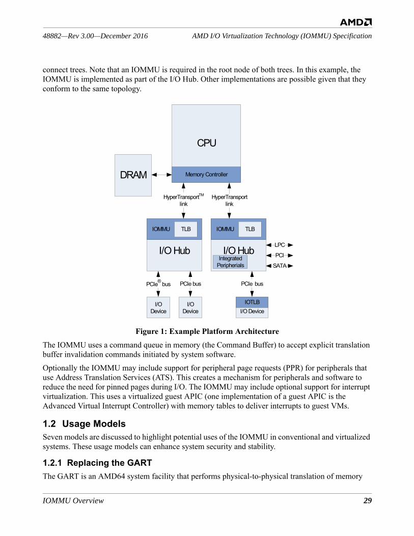
IOMMU Overview 29
AMD I/O Virtualization Technology (IOMMU) Specification48882—Rev 3.00—December 2016
connect trees. Note that an IOMMU is required in the root node of both trees. In this example, the IOMMU is implemented as part of the I/O Hub. Other implementations are possible given that they conform to the same topology.
Figure 1: Example Platform ArchitectureThe IOMMU uses a command queue in memory (the Command Buffer) to accept explicit translation buffer invalidation commands initiated by system software.Optionally the IOMMU may include support for peripheral page requests (PPR) for peripherals that use Address Translation Services (ATS). This creates a mechanism for peripherals and software to reduce the need for pinned pages during I/O. The IOMMU may include optional support for interrupt virtualization. This uses a virtualized guest APIC (one implementation of a guest APIC is the Advanced Virtual Interrupt Controller) with memory tables to deliver interrupts to guest VMs.
1.2 Usage ModelsSeven models are discussed to highlight potential uses of the IOMMU in conventional and virtualized systems. These usage models can enhance system security and stability.
1.2.1 Replacing the GARTThe GART is an AMD64 system facility that performs physical-to-physical translation of memory
DRAM
CPU
Memory Controller
I/O Hub
IOMMU TLB
I/O Hub
IOMMU
HyperTransportTM
linkHyperTransport
link
I/O Device
I/O Device I/O Device
TLB
IOTLB
PCIe® bus PCIe bus PCIe bus
PCI
LPC
SATAIntegrated
Peripherials
30 IOMMU Overview
48882—Rev 3.00—December 2016AMD I/O Virtualization Technology (IOMMU) Specification
addresses within a graphics aperture. The GART was defined to allow complex graphical objects, such as texture maps, to appear to a graphics co-processor as if they were located in contiguous pages of memory, even though they are actually scattered across randomly allocated pages by most operat-ing systems. The GART translates all accesses to the graphics aperture, including loads and stores executed by the host processor as well as memory reads and writes performed by I/O devices. Only accesses whose system physical addresses are within the GART aperture are translated; however, the results of the translation can be any system physical address.To set up the equivalent translations for I/O device-initiated accesses, the host OS must:• Construct I/O page tables that specify the desired translations.• Make an entry in the Device Table pointing to the newly constructed I/O page tables.• Notify the IOMMU of the newly updated Device Table entry.At this point, all accesses by both the host processor and the graphics device are mapped to the same pages as they would have been by the GART.If the host OS changes the page protection or translation, it must update both the processor page tables and, if not shared, the I/O page tables and issue appropriate page-invalidate commands to both the processor and the IOMMU. Unlike the processor, the IOMMU requires page-invalidate com-mands after any change to the I/O page tables. (AMD64 processors do not require page-invalidate operations after changes to leaf page table entries that add permission and make no change to transla-tion.) Sharing of page tables is discussed in Section 2.2.1 [Updating Shared Tables] and Section 2.2.4 [Sharing AMD64 Processor and IOMMU Page Tables—GPA-to-SPA].Since the IOMMU offers no facilities for restarting device accesses to unmapped or protected addresses, all pages that the device might access must be mapped with appropriate permissions. In this respect the IOMMU is similar to the GART.
1.2.2 Replacing the Device Exclusion Vector MechanismThe Device Exclusion Vector (DEV) is a basic security mechanism that was introduced with the AMD64 Secure Virtual Machine (SVM) Architecture. Like the IOMMU, the DEV allows I/O devices to be classified into different domains. Associated with each domain is a bit vector, indexed by physi-cal page address, indicating whether I/O devices in that domain are allowed to access the correspond-ing physical page. The IOMMU provides protection and translation. If only protection is needed, software can create identity-mapped I/O page tables that specify the desired protection.
1.2.3 32-bit to 64-bit Legacy I/O Device MappingWith the advent of large physical memories, legacy 32-bit devices that rely on DMA can no longer arbitrarily access system memory. This complicates operating systems, which must introduce a dis-tinction between low memory and high memory and perform appropriate bookkeeping to ensure that legacy I/O devices are only commanded to perform transfers using low memory. The cost is not just complexity; to perform a transfer from a legacy I/O device to high memory, for example, the operat-ing system typically allocates a bounce buffer in low memory, performs the transfer in low memory, and then copies the result to the real destination in high memory. For high-bandwidth I/O devices like
IOMMU Overview 31
AMD I/O Virtualization Technology (IOMMU) Specification48882—Rev 3.00—December 2016
disk controllers and network interfaces, the performance cost of bounce buffer allocation and copying can be large.In some operating systems, the GART has been used to work around this problem. When the OS wishes to perform a transfer between a legacy I/O device and high memory, it allocates a portion of the GART aperture and maps those pages to high memory. It then commands the I/O device to exe-cute the transfer using the address within the GART aperture, which must be located in low memory. Although this approach avoids the cost of bounce buffer copies, it is less than desirable, since the rel-atively small GART aperture must be shared by all legacy I/O devices and any graphics processors in the system. The device drivers have additional locking and synchronization overhead associated with page allocation and de-allocation in the GART aperture and system performance may be degraded due to serialization waiting for the GART aperture to become available.The IOMMU provides a better solution. First, IOMMU translation applies to the full range of addresses an I/O device can generate, rather than requiring high-memory transfers to be mapped only within the narrow range of GART addresses. Moreover, the IOMMU's ability to assign each I/O device to a different domain means that heavily used I/O devices can be given their own sets of I/O page tables and do not have to contend with other I/O devices for allocation and de-allocation of I/O pages.
1.2.4 User Mode Device AccessesThe IOMMU plays a crucial role in allowing arbitrary I/O devices to be safely controlled by user-level processes, since I/O devices whose memory accesses are translated by the IOMMU can only access pages that are explicitly mapped by the associated I/O page tables. The I/O devices' access can therefore be limited to those pages to which the user processes legitimately have access.Setting up the IOMMU for user-level I/O to an I/O device may be set up similarly to GART emulation with two differences; first, the mappable address range is the entire range of I/O device-generatable addresses, and secondly, the operating system is not necessarily required to make exactly equivalent mappings in the processor page tables (although most likely it will).Even with the help of the IOMMU, enabling user level I/O device access involves many design con-siderations. Protecting and remapping DMA is one part of the problem; the other part is interrupt management, for which the IOMMU provides help.As was the case with GART emulation, system software must assess the need to lock in memory all pages that might ever be accessed by an I/O Device controlled by a user-level process. It may be pos-sible to avoid needing to lock in memory if an I/O Device can use peripheral page request (PPR) mechanism, optionally implemented by IOMMU, to generate page fault as and when it touches a page.
1.2.5 Virtual Machine Guest Access to DevicesThe IOMMU can be used to allow unmodified virtual machine guest operating systems to directly access I/O devices. This is really just a special case of allowing user-level access to I/O devices, but there are a few considerations that warrant separate mention.First of all, a non-VM-aware guest has no current way of informing its Hypervisor (HV) which pages
32 IOMMU Overview
48882—Rev 3.00—December 2016AMD I/O Virtualization Technology (IOMMU) Specification
an I/O device might access, so the HV must lock the entire guest in memory. The HV’s I/O page tables for the guest should then simply map guest physical addresses to system physical addresses. If the HV is running the guest under nested paging and is using nested page tables built to be compatible with the IOMMU, then the IOMMU can directly share the host CPU page tables for the guest.Often a single virtual machine (VM) guest has direct access to multiple I/O devices. By design, all I/O devices in the guest that need to see exactly the same I/O page translations can share a DomainID (see “Data Structures” on page 52). If all the I/O devices belonging to a given VM guest are assigned to the same domain then the IOMMU can share translation cache entries among any of the guest’s I/O devices.Finally, guest I/O throughput is often significantly enhanced when guest memory is allocated using large pages on the host system. Then the I/O page tables can similarly use large pages and the IOMMU is more likely to avoid thrashing in its translation cache.
1.2.6 Virtualizing the IOMMUThe IOMMU has been designed so that it can be emulated in software by a HV that wishes to present its VM guests the illusion that they have an IOMMU.HVs that run non-VM-aware guests already intercept and emulate attempts by their guests to access PCI configuration space. Therefore, emulation of the IOMMU configuration registers is straightfor-ward; the emulation can be hooked directly to the existing facilities of the HV for intercepting PCI configuration space accesses.The HV must also arrange to intercept and emulate guest accesses to the IOMMU's MMIO-mapped command registers. Since the overhead of each HV intercept is high, guest operating systems access-ing the IOMMU have better performance when they enqueue batches of commands in the IOMMU's Command Buffer located in system memory prior to initiating IOMMU command processing via an MMIO register access. Since an untrusted guest OS cannot be allowed to write in the real Device Table, the HV must main-tain shadow entries in the real table on behalf of the guest. The IOMMU architecture requires soft-ware to issue invalidate-entry commands to the IOMMU after updating Device Table entries. The HV can intercept these invalidate commands, look up the corresponding entries in the guest's simulated Device Table, and make shadow entries in the real Device Table on behalf of the guest. Note that the DeviceIDs as seen by the guest need not be the same as the real DeviceIDs and the DomainIDs used by the guest are almost certainly different from the DomainIDs used by the HV in the real Device Table.In addition, for each guest VM I/O page table, the HV must construct a shadow I/O page table. This shadow I/O page table is the page table that is given to the real IOMMU. Unfortunately, since an incomplete I/O device access cannot be restarted, the HV must construct each guest domain's com-plete shadow I/O page tables eagerly as soon as the guest enables paging for that domain. The HV must write-protect guest I/O page tables from the guest in order to intercept all guest updates and propagate the updates to the shadow I/O page tables.The Hypervisor (HV) can also implement a subset of the IOMMU optional features by reporting that subset via the IOMMU Extended Feature Register [MMIO Offset 0030h]. The subset of additional
IOMMU Overview 33
AMD I/O Virtualization Technology (IOMMU) Specification48882—Rev 3.00—December 2016
features can be implemented using the same techniques described above.
1.2.7 Virtualized User Mode Device AccessesAn IOMMU with two-level translation enforces system protection policies while allowing arbitrary I/O devices to be properly controlled by user-level processes in a virtualized system. As noted in Sec-tion 1.2.4 [User Mode Device Accesses], I/O devices whose memory accesses are translated by the IOMMU can only access pages that are explicitly mapped by the associated I/O page tables as granted by the HV and operating system. The I/O devices' access can therefore be limited to only those pages to which the user-level processes legitimately have access when the device supplies PASID information. This means I/O operations can be initiated without hypervisor or operating sys-tem intervention.In addition to address translation, enabling user level I/O device access involves other design consid-erations such as remapping interrupts.System software must assess the need to lock in memory all pages that might ever be accessed by an I/O device controlled by a user-level process. Peripherals that use ATS can use the peripheral page request mechanism when implemented by an IOMMUto avoid needing to lock in all pages. As was the case with GART emulation, system software must assess the need to lock in memory all pages that might ever be accessed by an I/O device controlled by a user-level process. If a peripheral has support for the PCI Express ATS protocol and implements an IOTLB and in addition implements sup-port for the optional Peripheral Page Request protocol (PRI/PPR), then system software (Operating System or Hypervisor) is able to support pageable memory access for user level controlled I/O devices.
1.3 IOMMU Optional FeaturesAll implementations of the IOMMU provide a base set of capabilities. This base functionality is also known as IOMMU Revision 1.Subsequent revisions of this specification added new software-observable features. All these features are technically optional, although most IOMMU implemenations included all of the features that were defined at the time of their design.Architecturally, however, software must determine support for each feature and must enable each fea-ture before using it. Optional features include:• Guest virtual to guest physical address translation capability• AMD64 long mode page table compatibility• Support for PCI ATS• Support for PCI-SIG PRI and PASID TLP prefix ECN • Support for a guest virtual APIC (e.g., AVIC)• Enhanced performance and error logging features• Guest page table User/Supervisor access privilege checking• Guest page table Global Supervisor-level access protection
34 IOMMU Overview
48882—Rev 3.00—December 2016AMD I/O Virtualization Technology (IOMMU) Specification
• Guest page table non-executable page protection• Segmentation of the Device Table• PPR and Event Log dual buffers with optional autoswap• PPR Auto Response with Always-on feature• PPR Log early overflow warning• Device-specific feature reporting registers• MMIO access to MSI setup and mapping configuration space fields• Memory Access Routing and Control (MARC)• Automatic Block StopMark Message Handling• Guest I/O ProtectionAll implementations of the IOMMU support basic capabilities such as Device Virtual to System Physical Address translation, interrupt remapping, and access permissions checking. To determine if a particular implementation of the IOMMU supports any of the architecturally-defined optional fea-tures, software must first check that the EFRSup bit of the IOMMU Capability Header [Capability Offset 00h] (EFR) is set. If the EFRSup bit is set, the IOMMU Extended Feature Register [MMIO Offset 0030h] is supported. By reading the EFR software can determine which of the optional fea-tures are supported by the particular IOMMU present in that system. In most cases, support for a fea-ture is indicated by a non-zero value in the respective field of the EFR.The EFRSup bit and many of the feature and capability reporting fields related to I/O virtualization are replicated in the IOMMU ACPI Tables. Information reported via this method supersedes informa-tion reported via the Extended Feature Register and the Miscellaneous Information Register. See Chapter 5, "I/O Virtualization ACPI Table". Software Implementation Note: Software should not rely on the feature support information con-veyed by the IOMMU Extended Feature Register for any feature that is also reported in the ACPI tables since system firmware can override the functional capabilities reported by the IOMMU hard-ware.
Table 2 below lists all the architecturally defined features and specifies the field to test to determine support for that feature. In the table, EFR refers to the IOMMU Extended Feature Register [MMIO Offset 0030h], CapHdr refers to the IOMMU Capability Header [Capability Offset 00h], and CNTRL refers to the IOMMU Control Register [MMIO Offset 0018h].
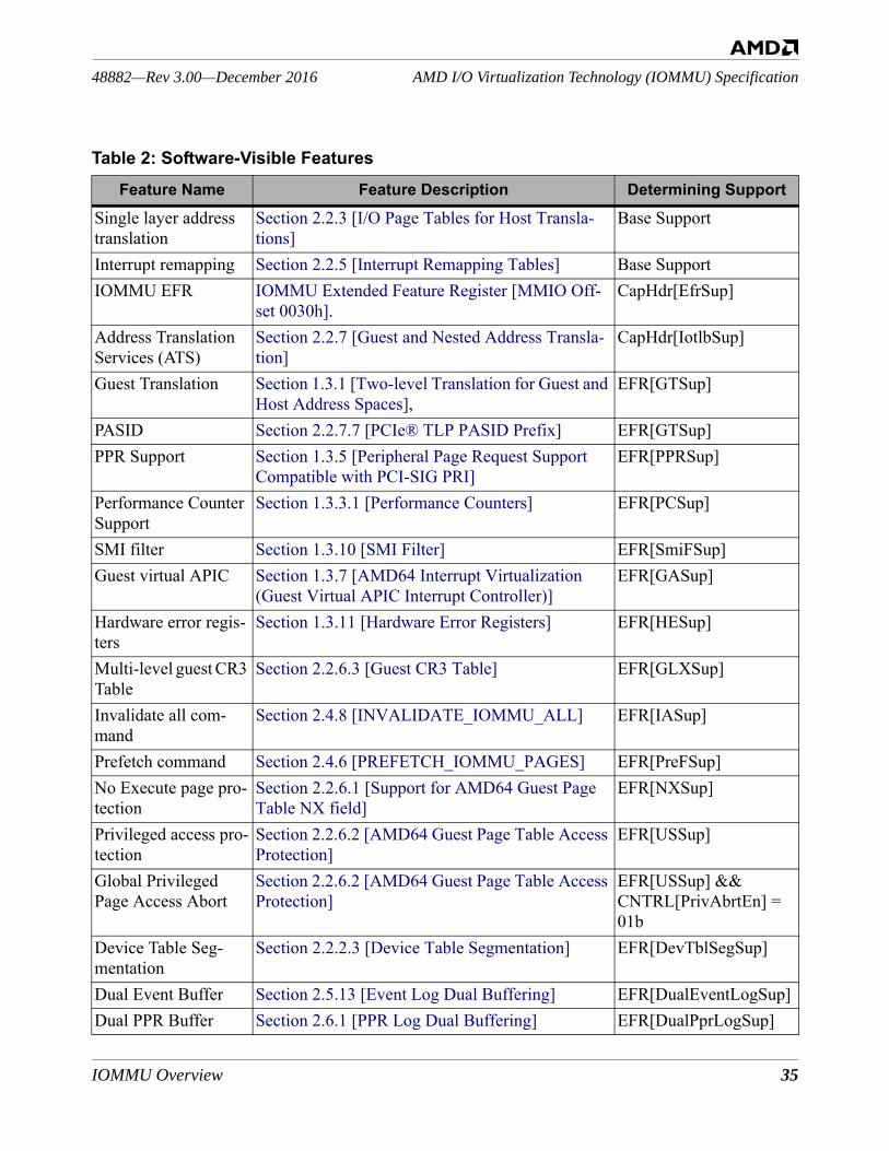
IOMMU Overview 35
AMD I/O Virtualization Technology (IOMMU) Specification48882—Rev 3.00—December 2016
Table 2: Software-Visible FeaturesFeature Name Feature Description Determining Support
Single layer address translation
Section 2.2.3 [I/O Page Tables for Host Transla-tions]
Base Support
Interrupt remapping Section 2.2.5 [Interrupt Remapping Tables] Base SupportIOMMU EFR IOMMU Extended Feature Register [MMIO Off-
set 0030h].CapHdr[EfrSup]
Address Translation Services (ATS)
Section 2.2.7 [Guest and Nested Address Transla-tion]
CapHdr[IotlbSup]
Guest Translation Section 1.3.1 [Two-level Translation for Guest and Host Address Spaces],
EFR[GTSup]
PASID Section 2.2.7.7 [PCIe® TLP PASID Prefix] EFR[GTSup]PPR Support Section 1.3.5 [Peripheral Page Request Support
Compatible with PCI-SIG PRI]EFR[PPRSup]
Performance Counter Support
Section 1.3.3.1 [Performance Counters] EFR[PCSup]
SMI filter Section 1.3.10 [SMI Filter] EFR[SmiFSup]Guest virtual APIC Section 1.3.7 [AMD64 Interrupt Virtualization
(Guest Virtual APIC Interrupt Controller)]EFR[GASup]
Hardware error regis-ters
Section 1.3.11 [Hardware Error Registers] EFR[HESup]
Multi-level guest CR3 Table
Section 2.2.6.3 [Guest CR3 Table] EFR[GLXSup]
Invalidate all com-mand
Section 2.4.8 [INVALIDATE_IOMMU_ALL] EFR[IASup]
Prefetch command Section 2.4.6 [PREFETCH_IOMMU_PAGES] EFR[PreFSup]No Execute page pro-tection
Section 2.2.6.1 [Support for AMD64 Guest Page Table NX field]
EFR[NXSup]
Privileged access pro-tection
Section 2.2.6.2 [AMD64 Guest Page Table Access Protection]
EFR[USSup]
Global Privileged Page Access Abort
Section 2.2.6.2 [AMD64 Guest Page Table Access Protection]
EFR[USSup] && CNTRL[PrivAbrtEn] = 01b
Device Table Seg-mentation
Section 2.2.2.3 [Device Table Segmentation] EFR[DevTblSegSup]
Dual Event Buffer Section 2.5.13 [Event Log Dual Buffering] EFR[DualEventLogSup] Dual PPR Buffer Section 2.6.1 [PPR Log Dual Buffering] EFR[DualPprLogSup]
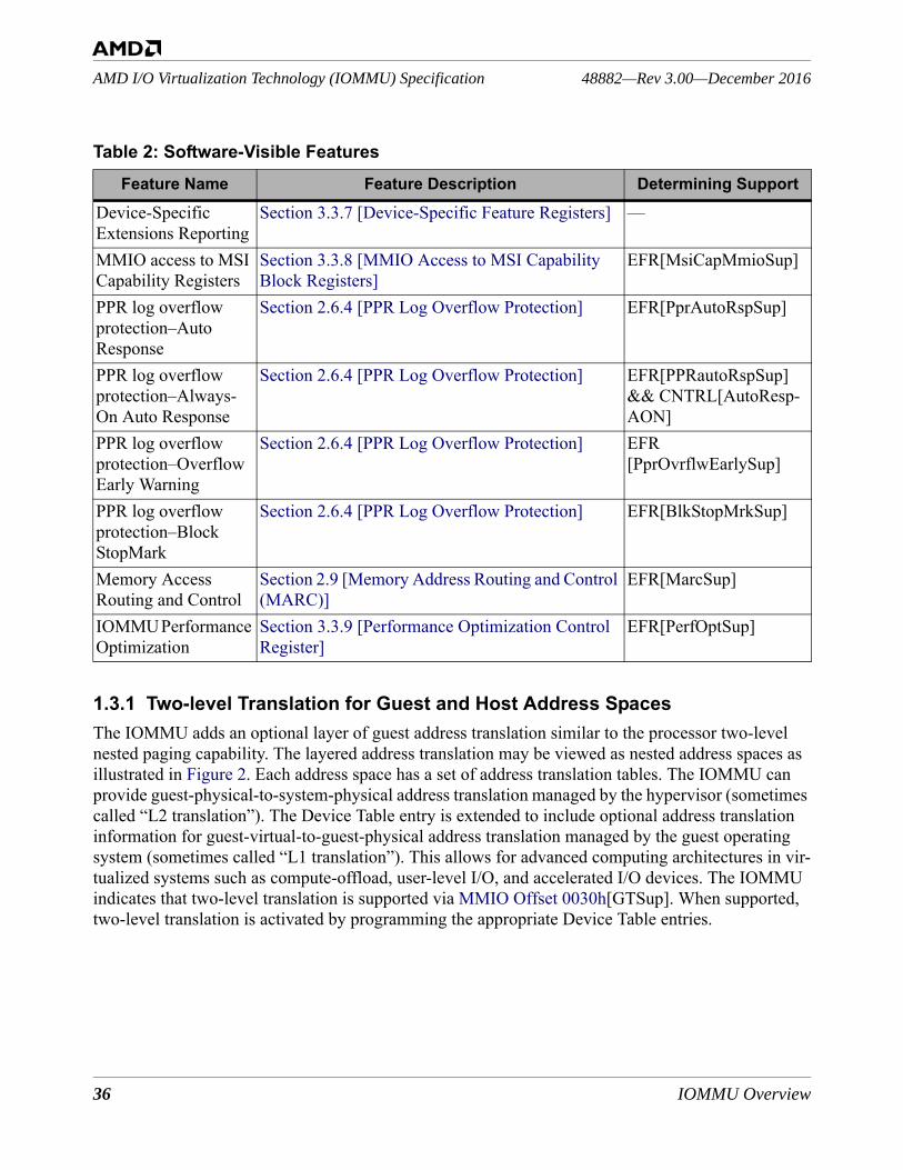
36 IOMMU Overview
48882—Rev 3.00—December 2016AMD I/O Virtualization Technology (IOMMU) Specification
1.3.1 Two-level Translation for Guest and Host Address SpacesThe IOMMU adds an optional layer of guest address translation similar to the processor two-level nested paging capability. The layered address translation may be viewed as nested address spaces as illustrated in Figure 2. Each address space has a set of address translation tables. The IOMMU can provide guest-physical-to-system-physical address translation managed by the hypervisor (sometimes called “L2 translation”). The Device Table entry is extended to include optional address translation information for guest-virtual-to-guest-physical address translation managed by the guest operating system (sometimes called “L1 translation”). This allows for advanced computing architectures in vir-tualized systems such as compute-offload, user-level I/O, and accelerated I/O devices. The IOMMU indicates that two-level translation is supported via MMIO Offset 0030h[GTSup]. When supported, two-level translation is activated by programming the appropriate Device Table entries.
Device-Specific Extensions Reporting
Section 3.3.7 [Device-Specific Feature Registers] —
MMIO access to MSI Capability Registers
Section 3.3.8 [MMIO Access to MSI Capability Block Registers]
EFR[MsiCapMmioSup]
PPR log overflow protection–Auto Response
Section 2.6.4 [PPR Log Overflow Protection] EFR[PprAutoRspSup]
PPR log overflow protection–Always-On Auto Response
Section 2.6.4 [PPR Log Overflow Protection] EFR[PPRautoRspSup] && CNTRL[AutoResp-AON]
PPR log overflow protection–Overflow Early Warning
Section 2.6.4 [PPR Log Overflow Protection] EFR[PprOvrflwEarlySup]
PPR log overflow protection–Block StopMark
Section 2.6.4 [PPR Log Overflow Protection] EFR[BlkStopMrkSup]
Memory Access Routing and Control
Section 2.9 [Memory Address Routing and Control (MARC)]
EFR[MarcSup]
IOMMU Performance Optimization
Section 3.3.9 [Performance Optimization Control Register]
EFR[PerfOptSup]
Table 2: Software-Visible FeaturesFeature Name Feature Description Determining Support
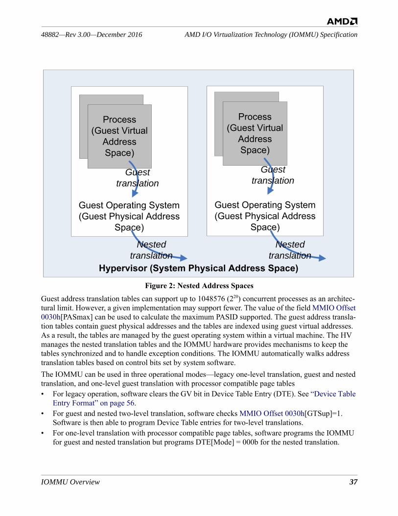
IOMMU Overview 37
AMD I/O Virtualization Technology (IOMMU) Specification48882—Rev 3.00—December 2016
Figure 2: Nested Address SpacesGuest address translation tables can support up to 1048576 (220) concurrent processes as an architec-tural limit. However, a given implementation may support fewer. The value of the field MMIO Offset 0030h[PASmax] can be used to calculate the maximum PASID supported. The guest address transla-tion tables contain guest physical addresses and the tables are indexed using guest virtual addresses. As a result, the tables are managed by the guest operating system within a virtual machine. The HV manages the nested translation tables and the IOMMU hardware provides mechanisms to keep the tables synchronized and to handle exception conditions. The IOMMU automatically walks address translation tables based on control bits set by system software.The IOMMU can be used in three operational modes—legacy one-level translation, guest and nested translation, and one-level guest translation with processor compatible page tables• For legacy operation, software clears the GV bit in Device Table Entry (DTE). See “Device Table
Entry Format” on page 56.• For guest and nested two-level translation, software checks MMIO Offset 0030h[GTSup]=1.
Software is then able to program Device Table entries for two-level translations. • For one-level translation with processor compatible page tables, software programs the IOMMU
for guest and nested translation but programs DTE[Mode] = 000b for the nested translation.
Hypervisor (System Physical Address Space)
Guest Operating System(Guest Physical Address
Space)
Guest Operating System(Guest Physical Address
Space)
Process(Guest Virtual
Address Space)
Guesttranslation
Nestedtranslation
Process(Guest Virtual
Address Space)
Guesttranslation
Nestedtranslation
38 IOMMU Overview
48882—Rev 3.00—December 2016AMD I/O Virtualization Technology (IOMMU) Specification
1.3.2 Enhanced Processor Page Table CompatibilityIn its base functionality, the IOMMU can share nested (host) page tables with an AMD64 processor when the Reserved fields are programmed to zeros. In contrast to the processor, the IOMMU does not re-walk page tables when an access violation is detected using cached information. When the IOMMU detects an access violation in a nested transaction, either from a TLB hit or from a page-table walk (TLB miss), it blocks the access or returns an ATS response with the calculated access privileges. When the IOMMU determines the proper access privileges are present, it allows the requested access or returns an ATS response with the calculated access privileges. Processor Page Table Compatibility Feature. The compatibility of the IOMMU with AMD64 long mode page tables is enhanced when operating in AMD64 mode. The IOMMU can directly share AMD64 long mode page tables with the processor for guest address translations. The guest page translation tables are strictly compatible with the AMD64 long mode format and semantics, including IOMMU updates to the Accessed and Dirty bits (see Section 2.2.6 [I/O Page Tables for Guest Trans-lations] and Section 2.2.7.4 [Updating Accessed and Dirty Bits in the Guest Address Tables]). When guest translation is used, the IOMMU follows the AMD64 long mode address translation require-ments for guest virtual addresses and thus software is not required to issue an invalidation command when it promotes guest access privileges; only when software demotes guest access privileges or removes the guest page (“present to not-present”) must software issue an invalidation. Therefore an ATS request or DMA reference that results in insufficient guest privileges calculated from a TLB entry may be based on stale information. To determine current permissions, the IOMMU rewalks the guest page tables to recompute access permission using information read from memory. The nested page tables may be read as a consequence of the guest table rewalk. The IOMMU determines the results of the access based on the newly read page table information. The rewalk may require a full walk of both guest and nested translations. Details are in Section 2.2.7 [Guest and Nested Address Translation]). The AMD64 long mode page tables contain information about memory types in the Page Attribute Table (PAT); the IOMMU can provide memory type information to a peripheral but does not interpret or validate the information.
1.3.3 Performance FeaturesThe IOMMU provides three performance-oriented features: performance counters, the PREFETCH command, and the FLUSH_ALL command.1.3.3.1 Performance CountersTo provide system software with consistent performance monitoring and evaluation mechanisms, an optional set of performance counters are defined. Support is indicated by the PCSup bit of the IOMMU Extended Feature Register [MMIO Offset 0030h]. An implementation may provide coun-ters in addition to the architecturally defined counters. The counters run independently from proces-sor activity. The counters are organized into n counter banks, each of which fits in a 4-Kbyte page. The HV may privately control all counter banks or assign one or more counter banks to a guest oper-ating system. The number of counters and counter banks are reported to system software (see Section 3.3 [IOMMU MMIO Registers] and Section 5.2.2.1 [I/O Virtualization Hardware Definition (IVHD) Block]). Each counter bank has controls that filter for devices and event sources of interest. Each event counter is programmed to count events or the duration of the events and each counter register
IOMMU Overview 39
AMD I/O Virtualization Technology (IOMMU) Specification48882—Rev 3.00—December 2016
has an optional signal for thresholding purposes (see Section 2.5.11 [EVENT_COUNTER_ZERO Event]). When performance counters are supported (MMIO Offset 0030h[PCSup] = 1), software must allocate a 512-Kbyte region of contiguous system memory for the IOMMU MMIO registers. The region must be 4-Kbyte aligned. If performance counters are not supported by the IOMMU (MMIO Offset 0030h[PCSup] = 0), the allocation requirement drops to 16 Kbytes.1.3.3.2 Loading the IOMMU TLBThe optional PREFETCH_IOMMU_PAGES command gives system software the ability to load the IOMMU TLB with relevant translation information (see Section 2.4.6 [PREFETCH_IOMMU_PAGES]), especially error processing information (Section 2.4.6.1 [Event Processing for PREFETCH_IOMMU_PAGES]). Support for the prefetch feature is indicated by MMIO Offset 0030h[PreFSup]. If PreFSup=0, a PREFETCH_IOMMU_PAGES command causes the IOMMU to create an error event (Section 2.5.6 [ILLEGAL_COMMAND_ERROR Event]). Because a TLB is a caching structure, the prefetch com-mand must be considered advisory. Even if the IOMMU were to fetch the address translation infor-mation for every prefetch command, the TLB entry may be overwritten by other translation information before it is ever used and an attempt to use the translation information would cause a page table walk after all. The PREFETCH_IOMMU_PAGES command is a hint to the IOMMU that the associated translation records will be needed relatively soon and that the IOMMU should execute a page table walk to load the translation information. Based on internal status and workloads, the IOMMU may fetch the trans-lation information into a TLB. If an entry is already in the TLB, the IOMMU may adjust LRU or other control tags to lengthen cache residency. 1.3.3.3 Flushing the IOMMU TLBThe base function of the IOMMU provides the INVALIDATE_DEVTAB_ENTRY command (per DeviceID), the INVALIDATE_IOMMU_PAGES command (per DomainID), and the INVALIDATE_INTERRUPT_TABLE command (per DeviceID) which software can use to invali-date I/O TLB entries. The optional INVALIDATE_IOMMU_ALL command may simplify trusted boot, error recovery, and resumption from low-power states (see Section 2.4.8 [INVALIDATE_IOMMU_ALL]). At the com-pletion of an INVALIDATE_IOMMU_ALL command, all IOMMU TLBs are invalidated, including cached portions of the Device Table, guest CR3 table, page directory entries, page table entries, and interrupt remapping entries (including the Guest APIC Table Root Pointer). Section 2.4.9 [IOMMU Ordering Rules] describes how outstanding operations must be handled. The operational status of the IOMMU is not affected by INVALIDATE_IOMMU_ALL. Translations, command and event processing, address translation requests, and peripheral page request processing continue normally. The contents of the MMIO registers are not affected except to advance the Com-mand Buffer Head Pointer Register [MMIO Offset 2000h] beyond the INVALIDATE_IOMMU_ALL command. The IOMMU may start reloading internal caches with information at any time after the INVALIDATE_IOMMU_ALL command completes. The INVALIDATE_IOMMU_ALL command
40 IOMMU Overview
48882—Rev 3.00—December 2016AMD I/O Virtualization Technology (IOMMU) Specification
guarantees ordering as described in Section 2.4.9 [IOMMU Ordering Rules].Note that the INVALIDATE_IOMMU_ALL command does not invalidate remote IOTLBs. In the case of ATS, invalidation can be achieved by disabling and re-enabling ATS on each PCI device/func-tion.Support for the INVALIDATE_IOMMU_ALL command is indicated by the IASup bit of the IOMMU Extended Feature Register [MMIO Offset 0030h].
1.3.4 Address Translation Services for Guest Virtual AddressesBase Function. Address translation services can be used by a peripheral to translate a GPA to an SPA. To translate a GPA to an SPA, a PCIe®-connected peripheral issues an ATS request lacking a PASID TLP prefix recognized by the IOMMU (see Section 2.2.7.7 [PCIe® TLP PASID Prefix]). The IOMMU evaluates access privileges using cached information and walks the page tables when required. The resulting access privileges are returned in the ATS response. Optional Enhancements. Address translation services can be used by a peripheral to translate a GVA or GPA to an SPA. To translate a GVA to an SPA, a peripheral issues an ATS protocol request. The request contains a valid PASID, the access attribute flags and a (canonical) virtual address (see Sec-tion 1.3.6 [Selecting Translation Tables in a Memory Transaction] and Section 2.2.7.7 [PCIe® TLP PASID Prefix]). An integrated peripheral may use means other than the ATS protocol to present flags and the virtual address, such as wire signals. The IOMMU evaluates access privileges using cached information for efficiency and walks the page tables when required. To match AMD64 semantics, the IOMMU must re-walk the guest page tables if previously cached information indicate insufficient privileges for the access (see Section 2.2.7.1 [Combining Guest and Host Address Translation] and Table 32 on page 106). The resulting access privileges are returned in the ATS response. To carry the additional information for a guest address, the IOMMU uses a PCIe TLP prefix containing a valid PASID.The IOMMU must update the Accessed and Dirty bits in the GVA page table while servicing an ATS request as if the peripheral had actually accessed memory (see Section 2.2.7.4 [Updating Accessed and Dirty Bits in the Guest Address Tables]). For the purpose of evaluating GVA Accessed and Dirty bits, the IOMMU must use the access level indicated in the ATS packet. An ATS request for read-only access determines the Accessed bit setting and an ATS request for read-write access determines the Dirty bit setting (see Table 32 on page 106). When processing a GPA, the IOMMU treats the page tables as read-only. Software Note: Software must issue an invalidation command when it changes A or D bits in a page table entry to 0 from 1. This requirement allows the IOMMU to cache the A & D bits in a TLB for higher performance.
Software issues an INVALIDATE_IOTLB_PAGES command to cause the IOMMU to generate an invalidation request to the peripheral (see Section 2.4.4 [INVALIDATE_IOTLB_PAGES]). An invalidation request sent to the device lacks a valid PASID prefix when the contents are a GPA. An invalidation request sent downstream to the device has a valid PASID prefix when the contents are a GVA and the PASID is in the PASID TLP prefix field of the command.The conditions under which a peripheral with an IOTLB must invalidate a cached translation entry
IOMMU Overview 41
AMD I/O Virtualization Technology (IOMMU) Specification48882—Rev 3.00—December 2016
that caused an insufficient-privilege check and obtain a fresh translation using ATS are described in Section 2.1.4.8 [Discarding IOTLB Information to Rewalk Page Tables].
1.3.5 Peripheral Page Request Support Compatible with PCI-SIG PRIIOMMU optionally supports the PCI-SIG PRI specification as a complement to PCI-SIG Address Translation Service (ATS) specification (see Section 2.1.1 [Normal Operation]). The IOMMU sup-port for PRI is called peripheral page request (PPR) logging (see Section 2.6 [Peripheral Page Request (PPR) Logging]). The operating system is usually required to pin memory pages used for I/O; the pinned pages are often allocated from a separate memory pool of limited capacity. ATS and PRI can be used together to enable the peripheral to use unpinned pages for I/O. When processing ATS requests, the IOMMU does not signal events when insufficient access privileges or not-present pages are detected; instead it returns the permissions calculated from the page tables. The peripheral examines the response to determine an appropriate action (e.g., use PRI to request system software to service a page table entry). Use of PRI/PPR allows a peripheral to request the operating system to change the access priv-ileges of the page or request the page to be made present in the memory (it was not present).. Use of ATS with PRI/PPR can allow a system to operate efficiently under low available memory.
1.3.6 Selecting Translation Tables in a Memory TransactionIn the base capabilities of the IOMMU, a PCIe packet contains a GPA and the originating BDF is used to select GPA-to-SPA translation tables. A PCI-SIG TLP prefix is not interpreted by the IOMMU. An optional feature adds support for translating guest virtual addresses to system physical addresses using the page tables programmed by the guest operating system. The PCI-SIG defines a method to add information to a transaction called the TLP prefix. When a PCIe transaction has a PASID TLP prefix, the packet contains a canonical GVA and the TLP prefix selects the guest tables for GVA-to-GPA translation; when a PCIe transaction has no TLP prefix, the packet contains a GPA. The originat-ing BDF is used to select GPA-to-SPA translation tables. Details are in Section 2.2.7.7 [PCIe® TLP PASID Prefix].
1.3.7 AMD64 Interrupt Virtualization (Guest Virtual APIC Interrupt Controller)The IOMMU optionally supports interrupt virtualization . Device interrupts can be delivered directly to running guest virtual machines without hypervisor intervention when interrupts are virtualized (see MMIO Offset 0030h[GASup] and MMIO Offset 0018h[GAEn]). This can reduce the delivery latency and overhead of guest VM interrupts. This feature requires compatible APIC virtualization support in the processor. The processor and the IOMMU coordinate to maintain interrupt state in the Guest Vir-tual APIC Table when delivering interrupts. Interrupt remapping and interrupt virtualization may be enabled independently. See details in Section 2.2.8 [Guest Virtual APIC Table for Interrupt Virtual-ization].
1.3.8 Enhanced Support for Access and Dirty BitsAccess bit (A) in page descriptor indicates whether the physical page to which the descriptor points to has been accessed. Dirty bit (D) in a page descriptor indicates whether the page-translation table or
42 IOMMU Overview
48882—Rev 3.00—December 2016AMD I/O Virtualization Technology (IOMMU) Specification
the physical page to which this descriptor points has been written to by a peripheral. The A bit in the guest page table is set to 1 by the IOMMU the first time the descriptor or the physical page is either read from or written to. The D bit in the guest page table is set to 1 by the IOMMU the first time a device writes to the physical page or the descriptor is accessed for an intended write to the corresponding physical page. Optionally IOMMU hardware can set A and D bit in the host page table (see IOMMU Extended Fea-ture Register [MMIO Offset 0030h] HASup and HDSup). When enabled the IOMMU will set A and D bits to host page table in process similar to that described in Section 2.2.7.4.Note that IOMMU hardware never clears A or D bits.System software can use the A bits to help decide to choose candidate pages for page out. D bits can be used to avoid redundant wirte-backs to storage.
1.3.9 Guest I/O ProtectionOptionally the IOMMU enables Guest I/O protection even for devices that do not support PASID [Refer to Section 2.2.9]. When enabled, a default PASID equal to 0 is assigned to DMA requests without PASID associated with the enabled DTE. The DMA requests then go through guest and nested translations as usual. Operating systems can use this feature to enable I/O protection buffers using guest page table for devices that may not support PASID.
1.3.10SMI FilterThe IOMMU optionally supports the interception of System Management Interrupts (SMI) that are unexpected by system firmware or software. SMIs that are vital to system operation and integrity are delivered as usual but SMIs from suspect sources can be blocked or deferred for later processing or analysis. See Section 2.1.5 [System Management Interrupt (SMI) Controls] for details of SMI filter operation.
1.3.11Hardware Error RegistersAll error events are reported in the IOMMU event log. Optionally, error reporting is enhanced by log-ging critical events in the hardware error registers. See IOMMU Hardware Event Upper Register [MMIO Offset 0040h], IOMMU Hardware Event Lower Register [MMIO Offset 0048h], and IOMMU Hardware Event Status Register [MMIO Offset 0050h].
Architecture 43
AMD I/O Virtualization Technology (IOMMU) Specification48882—Rev 3.00—December 2016
2 Architecture
This chapter describes the IOMMU's architecture mainly from a system software point of view. The discussion starts with the normal steady state behavior of the IOMMU once it has been set up, focus-ing on how the IOMMU handles various device transactions. The following section describes the in-memory data structures used to control the IOMMU, together with the procedures software must fol-low to correctly update these (shared) data structures. Finally, the chapter concludes with a descrip-tion of the PCI resources that must be initialized at system startup time to configure the IOMMU.
2.1 BehaviorWhen the IOMMU is disabled it simply passes all bus traffic through without alteration.When the IOMMU is enabled, it intercepts requests arriving from downstream devices (which may be attached to the system via a HyperTransport™ link, PCI bus, or other means), performs permission checks and address translation on the requests, and sends translated versions upstream to system memory. Other requests are passed through unaltered (details in Section 2.1.1 [Normal Operation]). PCI devices serviced by a single IOMMU must be on the same PCI Segment Group (see PCI Firm-ware specification for further details of PCI Segment Groups).The IOMMU reads three tables in system memory to perform its permission checks, interrupt remap-ping, and address translations. To avoid deadlock, memory accesses for device tables, page tables, and interrupt remapping tables by the IOMMU use an isochronous virtual channel and may only ref-erence addresses in system memory. Other memory reads originated by the IOMMU to command buffers, event log entries, and optional request queue entries use the normal virtual channel. System performance could be substantially reduced if the IOMMU performed the full table lookup process for every device request it handled. Therefore, implementations of the IOMMU are expected to main-tain internal caches for the contents of the IOMMU's in-memory tables, and correct operation of the IOMMU requires system software to send appropriate invalidation commands to the IOMMU when it updates table entries that may have been cached by the IOMMU.The IOMMU writes to the event log in system memory using the normal virtual channel. The IOMMU can optionally write to the peripheral page request log in system memory and these writes use the normal virtual channel. The IOMMU can optionally write to the guest virtual APIC log in sys-tem memory and these writes use the normal virtual channel.The IOMMU signals interrupts using standard PCI MSI or MSI-X interrupts.
2.1.1 Normal OperationThe typical flow of requests through the IOMMU is as follows:• Read, write and interrupt transactions generated by the IOMMU are not translated by the
IOMMU.• Transactions arriving from upstream must be passed downstream unaltered.• Transactions arriving from downstream that are response, fence, or flush commands must be
44 Architecture
48882—Rev 3.00—December 2016AMD I/O Virtualization Technology (IOMMU) Specification
passed upstream unaltered.• Transactions arriving from downstream that reference addresses within the IOMMU exclusion
range must be passed upstream unaltered.• Memory read and write transactions from downstream result in table lookups in the Device Table
to obtain the DomainID of the requesting I/O device and to locate I/O page tables. Further table lookups are required in I/O page tables to perform address translation and permission checking. After performing permission checks and address translation, the IOMMU forwards the resulting transactions upstream if the transaction is allowed from the I/O device.
• Address translation requests from downstream result in table lookups as for memory read and write transactions. Translated address and access permission information is returned to the requesting peripheral. Software is required to invalidate address translation mappings cached by a peripheral.
• Peripheral page requests from downstream result in an event log entry if not supported, or result in a peripheral page request log entry written to system memory. (Optional PPR Auto response modifies this behavior.)
• Interrupt addresses are never translated to system memory addresses, but Physical address ranges reserved for Message Signaled Interrupts (MSI) may be optionally treated as memory addresses for translation (e.g., ACPI address ranges, PCI configuration space mapping).
• Upstream interrupts result in table lookups in the Device Table and then in the interrupt remapping tables to remap the interrupt. After performing checks and interrupt remapping, the IOMMU forwards the resulting interrupts upstream if the interrupt is allowed from the I/O device. SMI requests optionally go through the SMI filter and do not use the interrupt remapping tables.
• Port I/O space transactions from downstream devices result in a Device Table lookup to determine if the I/O device is allowed to access port I/O space.
• The IOMMU maintains an event log in system memory containing the details of transactions that do not complete normally.
• The IOMMU maintains an optional guest virtual APIC log containing details of interrupt requests that arrive when the guest is not running.
• The IOMMU does not further translate pretranslated memory read and write requests from devices if the I/O device is marked as being able to generate pretranslated addresses.
• The IOMMU processes commands from the command queue.
The optional MARC feature allows accesses from integrated I/O devices such as GPUs to bypass the IOMMU when accessing defined regions of system memory.In addition to passing on transactions from downstream devices, the IOMMU inserts transactions of its own to perform reads to and writes from system memory and to signal interrupts.The IOMMU is allowed to cache page table and Device Table contents to speed up translations. An invalidation protocol is defined so that software can keep the cache contents consistent with memory when it updates the tables. When software initiates a suspend operation that does not preserve the state of the processor or chipset, the state of the IOMMU stored in registers is lost and must be restored as part of the resume sequence.

Architecture 45
AMD I/O Virtualization Technology (IOMMU) Specification48882—Rev 3.00—December 2016
When system software processes a PCI hot-plug notification, the ACPI tables should be inspected to determine the IOMMU that will service the peripheral and then program the IOMMU appropriately.
2.1.2 IOMMU Logical TopologyOnce configured, the IOMMU logically resides between the I/O devices and the upstream interface. As a result of this logical topology the transactions seen by the IOMMU are defined in terms of HyperTransport™ transactions. Accesses to the HyperTransport™ address range FD_0000_0000h -FF_FFFF_FFFFh, inclusive, have special meanings. The meaning is encoded into various portions of the address as shown in Table 3 and Table 19; complete details are in the HyperTransport™ I/O Link Specification. Upstream transactions to these address ranges are controlled by Device Table control bits, page tables or the interrupt remapping tables. The special address controls do not apply to pre-translated addresses.Special address controls in Table 3 are interpreted against untranslated guest physical addresses (GPA) that lack a PASID TLP prefix.
During configuration, an IOMMU may appear connected in different topologies that are implementa-tion dependent.
2.1.3 IOMMU Event ReportingThe IOMMU must detect and may report several kinds of events that may arise due to unusual hard-ware or software behavior. When the IOMMU detects an event of any kind and event logging is enabled, it writes an appropriate event entry into the event log located in system memory. In addition, it may optionally signal an interrupt when the event log is written.
Table 3: Special Address Controls (GPA)Base Address Top Address Use Access controlled byFD_0000_0000h FD_F7FF_FFFFh Reserved interrupt
address spaceSee Section 2.5.9 [INVALID_DEVICE_REQUEST Event]
FD_F800_0000h FD_F8FF_FFFFh Interrupt/EOI IntCtl, Interrupt Remapping Tables
FD_F900_0000h FD_F90F_FFFFh Legacy PIC IACK Page TablesFD_F910_0000h FD_F91F_FFFFh System Management SysMgt, Page TablesFD_F920_0000h FD_FAFF_FFFFh Reserved Page TablesFD_FB00_0000h FD_FBFF_FFFFh Address Translation HtAtsResv, Page TablesFD_FC00_0000h FD_FDFF_FFFFh I/O Space IoCtl, Page TablesFD_FE00_0000h FD_FFFF_FFFFh Configuration Page TablesFE_0000_0000h FE_1FFF_FFFFh Extended Configuration/
Device MessagesPage Tables
FE_2000_0000h FF_FFFF_FFFFh Reserved Page Tables
46 Architecture
48882—Rev 3.00—December 2016AMD I/O Virtualization Technology (IOMMU) Specification
Events detected by the IOMMU include I/O page faults as well as hardware memory errors detected when walking the I/O page tables. A detected event may cause a page table or interrupt remapping table walk to terminate before reaching the final memory-translation or interrupt-remap entry. When a walk is terminated early, the event information reported is based on the results calculated in the com-pleted portion of the walk, starting with the Device Table Entry (DTE).Software Note: the TLB caching behavior of the IOMMU is not defined for an entry causing an event; some implementations may insert an entry in the TLB cache before verifying that it causes no exceptions. System software should invalidate the address that caused the event.
2.1.3.1 IOMMU Event ResponsesThe IOMMU response to events depends on the type of event detected, the type of transaction that caused the event, and the state of the IOMMU at the time of the event. If an IOMMU is not enabled or does not support address translation requests, the IOMMU responds to translation requests with a master abort. If the IOMMU is enabled, it can have one of three event responses:• For upstream transactions that are master aborted or target aborted, the PCI/Host bridge that is co-
located with the IOMMU is the completer of the transaction. Transactions that are target aborted set the legacy Signaled Target Abort bit in a manner consistent with the bus specification over which the transaction was received (secondary port). These aborted transactions should not set any AER bits (if implemented and otherwise applicable).
• Exceptions detected in transactions that target the IOMMU function are not logged in the IOMMU event log. The exceptions are signaled following the rules of the bus specification applicable to the primary bus with which the IOMMU function is associated.
• Exceptions detected in the transactions originating from the IOMMU function signal the event following the rules of the bus specification applicable to the primary bus with which the IOMMU is associated. Additionally, exceptions in command buffer and table walk reads are logged in the IOMMU event log.
A transaction that attempts to use a Device Table entry beyond the end of the table is treated as in Table 44. The size of the Device Table is defined by the Device Table Base Address Register, MMIO Offset 0000h[Size].2.1.3.2 I/O Page FaultsThe IOMMU may detect page-fault conditions when processing peripheral requests and the response of the IOMMU depends on the type of the request and IOMMU control settings.A peripheral’s memory transaction may result in an I/O page fault. These page faults can arise for a variety of reasons, such as I/O page table entries lacking sufficient permission or memory pages marked not-present. In a traditional processor virtual memory implementation, page faults activate an exception handler that has the option to correct the underlying problem and retry the faulting instruc-tion. The IOMMU has no such option: the underlying HyperTransport™ and PCI bus protocols do not provide a means for the IOMMU to signal a device that it should attempt to retry an access. Con-sequently, when the IOMMU detects an I/O page fault, it target aborts the faulting request. The
Architecture 47
AMD I/O Virtualization Technology (IOMMU) Specification48882—Rev 3.00—December 2016
IOMMU sets the legacy PCI Signaled Target Abort bit, if appropriate, and records I/O page fault information in its event log when event logging is enabledFor an address translation request, the IOMMU returns the translation result and does not signal a fault (see also Section 2.1.4.5 [Address Translation Requests in the Special Address Range]). The peripheral can examine the translation response to determine if a particular memory transaction would cause an exception. Peripherals may request page fault service as described in Section 2.6 [Peripheral Page Request (PPR) Logging].2.1.3.3 Memory Access ErrorsThe IOMMU's own memory accesses to its in-memory tables may themselves result in several kinds of errors, including:• Accesses to nonexistent or non-DRAM addresses because the IOMMU's isochronous virtual
channel is restricted to DRAM addresses only.• Uncorrectable ECC errors.• Use of reserved values, including invalid or unsupported type codes in Device Table entries and
reserved bits in page table entries.
The IOMMU records all detected memory access errors in its event log when event logging is enabled. Optionally hardware errors may also be stored in the error registers (see Section 2.5.12.2 [I/O Hardware Event Reporting Registers]).
2.1.4 Special ConditionsThis section defines the behavior of the IOMMU for particular operating conditions.2.1.4.1 Zero-byte Read OperationsIn some bus architectures, a zero-byte read operation is defined as a special operation with well-defined side effects. Because of these side effects, the IOMMU must permit a zero-byte read opera-tion when a page is marked to allow either read or write access. Further, because the zero-byte read operation returns undefined data in some bus specifications, protecting the contents of a non-readable memory location requires that the IOMMU obscure the returned data for a zero-byte read operation. Implementation Note: methods to obscure the returned data in a zero-byte read operation include returning a constant, a random value, or a predictable value not based on the data contents such as the address.
2.1.4.2 Interrupt Address RangeAccesses to the interrupt address range (Table 3) are defined to go through the interrupt remapping portion of the IOMMU and not through address translation processing. Therefore, when a transaction is being processed as an interrupt remapping operation, the transaction attribute of pretranslated or untranslated is ignored. Software Note: The IOMMU should not be configured such that an address translation results in a special address such as the interrupt address range.
48 Architecture
48882—Rev 3.00—December 2016AMD I/O Virtualization Technology (IOMMU) Specification
2.1.4.3 Multi-page Address Translation Requests Lacking a PDEAn address translation transaction to the IOMMU can request multiple pages. The page size (stride) is generally determined by the PDE used with level=0 or level=7. The page stride is always a power of two. For situations where there is no relevant PDE (within the IOMMU exclusion range or when the DTE[Mode] = 0), the results returned by the IOMMU are implementation-specific. 2.1.4.4 Address Translation Requests in the IOMMU Exclusion RangeI/O devices may request address translations for addresses in the IOMMU exclusion range, defined by IOMMU Exclusion Base Register [MMIO Offset 0020h] and IOMMU Exclusion Range Limit Register [MMIO Offset 0028h], and may cache the results. When software changes the exclusion range, it must invalidate remote IOTLBs that may contain affected translation entries. Address trans-lation requests to the exclusion range always return permissions that allow reading and writingAn address translation request for a GPA within the exclusion range returns an implementation-defined result. 2.1.4.5 Address Translation Requests in the Special Address RangeI/O device address translation requests for a GPA within special address ranges in Table 3 are con-trolled by the SysMgt and IoCtl settings in the Device Table entry (see Section 2.2.2.1 [Device Table Entry Format]) and can either return a translation or cause a target abort. 2.1.4.6 Page Translation Entries Spanning Memory and Special Address RangesAn IOMMU address translation entry for a GPA may be constructed to cover both conventional mem-ory addresses and special addresses (see Table 3). The DTE[IoCtl] and DTE[SysMgt] fields control IOMMU behavior. To translate a GPA address in a special address range, set the corresponding spe-cial address range control in the DTE to direct the IOMMU to translate the desired special address ranges as memory addresses. 2.1.4.7 Discarding IOMMU TLB Information to Re-walk Page TablesAn optional feature adds the capability for the IOMMU to rewalk the page tables under certain condi-tions. When the IOMMU detects an access violation based on cached information, it discards the information in the IOMMU TLB and reloads the translation information from memory. Interrupt remapping information is only loaded from memory on a TLB miss. See Section 1.3.4 [Address Translation Services for Guest Virtual Addresses] for details.2.1.4.8 Discarding IOTLB Information to Rewalk Page TablesAn optional feature adds the capability for the IOMMU to rewalk the page tables under certain condi-tions. The peripheral can use address translation information from the IOTLB or obtained via ATS to determine access privileges for a nested (host) access. As an AMD extension, a peripheral with an IOTLB must invalidate a cached entry causing an insufficient-privilege failure when R=1 or W=1 in the IOTLB entry for a guest access. The peripheral must then request the guest translation informa-tion using ATS and retry the access. If the revised privileges are insufficient for the retry, the periph-eral must take appropriate action to abandon the access or issue a PCIe® PRI request for escalated privileges.
Architecture 49
AMD I/O Virtualization Technology (IOMMU) Specification48882—Rev 3.00—December 2016
2.1.4.9 Updating the Accessed and Dirty Bits in Guest Page TablesAn optional feature adds the capability for the IOMMU to write to the guest page table. The IOMMU must update the guest page table Accessed and Dirty bits atomically. The IOMMU never clears the Accessed or Dirty bits; software is responsible to clear the bits. The IOMMU is allowed to cache these bits, so software must issue invalidation commands when it clears the bits in a PTE. See Section 2.2.7.4 [Updating Accessed and Dirty Bits in the Guest Address Tables] and Section 2.2.7.5 [Clearing Accessed and Dirty Bits] for details.2.1.4.10 Address Translation Response When DTE[Mode] = 0A peripheral can request address translations when DTE[Mode] = 000b; The returned system physi-cal address (SPA) is equivalent to the guest physical address. 2.1.4.11 Page SplinteringWhen an address is mapped by guest and nested page table entries with different page sizes, the IOMMU TLB entry that is created matches the size of the smaller page (see also AMD64 Technology, AMD64 Architecture Programmer’s Manual, Volume 2: System Programming, Page Splintering).2.1.4.12 Atomic Operations Require Read and Write PermissionsAtomic operations both read and write a page. The IOMMU must permit atomic operations from the peripheral only when the page is marked to allow both read and write operations.2.1.4.13 INVALIDATE_IOTLB_PAGES and Peripheral ResetIf a peripheral is reset while an INVALIDATE_IOTLB_PAGES command is being executed by the IOMMU (Section 2.4.4 [INVALIDATE_IOTLB_PAGES]), the peripheral may stop processing invalidations and software must process any IOTLB_INV_TIMEOUT events that result (Section 2.5.8 [IOTLB_INV_TIMEOUT Event]).
2.1.5 System Management Interrupt (SMI) ControlsIn order to ensure AMD64 system management interrupts delivered to the processor come from valid peripheral sources (DeviceIDs), the IOMMU optionally supports an SMI filter. When MMIO Offset 0030h[SmiFSup]=00b or MMIO Offset 0018h[SmiFEn]=0b, SMI interrupts from any source are delivered to the processor(s); for other values of MMIO Offset 0030h[SmiFSup], SMI interrupts are filtered according to the values programmed in the SMI filter registers (see IOMMU SMI Filter Reg-ister [MMIO Offset 00[60-D8]h]). The number of SMI filter registers available is in MMIO Offset 0030h[SmiFRC]. Each SMI filter register contains a DeviceID and control bits; together, the set of SMI filter registers can be programmed to define the set of devices from which system management interrupts will be delivered.2.1.5.1 SMI Filter OperationWhile SMI filtering is enabled and supported by the IOMMU, each upstream SMI is checked to match against the SMI filter registers that are valid and enabled and an upstream SMI from a Devi-ceID failing to match any SMI filter register will be blocked. The fields MMIO Offset 0018h[Smi-FEn] and MMIO Offset 0018h[SmiFLogEn] control the behavior of the SMI filter. When SmiFEn=1b, an upstream SMI interrupt request that matches any of the valid SMI filter registers is delivered upstream without modification. When SmiFEn=1b and SmiFLogEn=0b, an upstream SMI
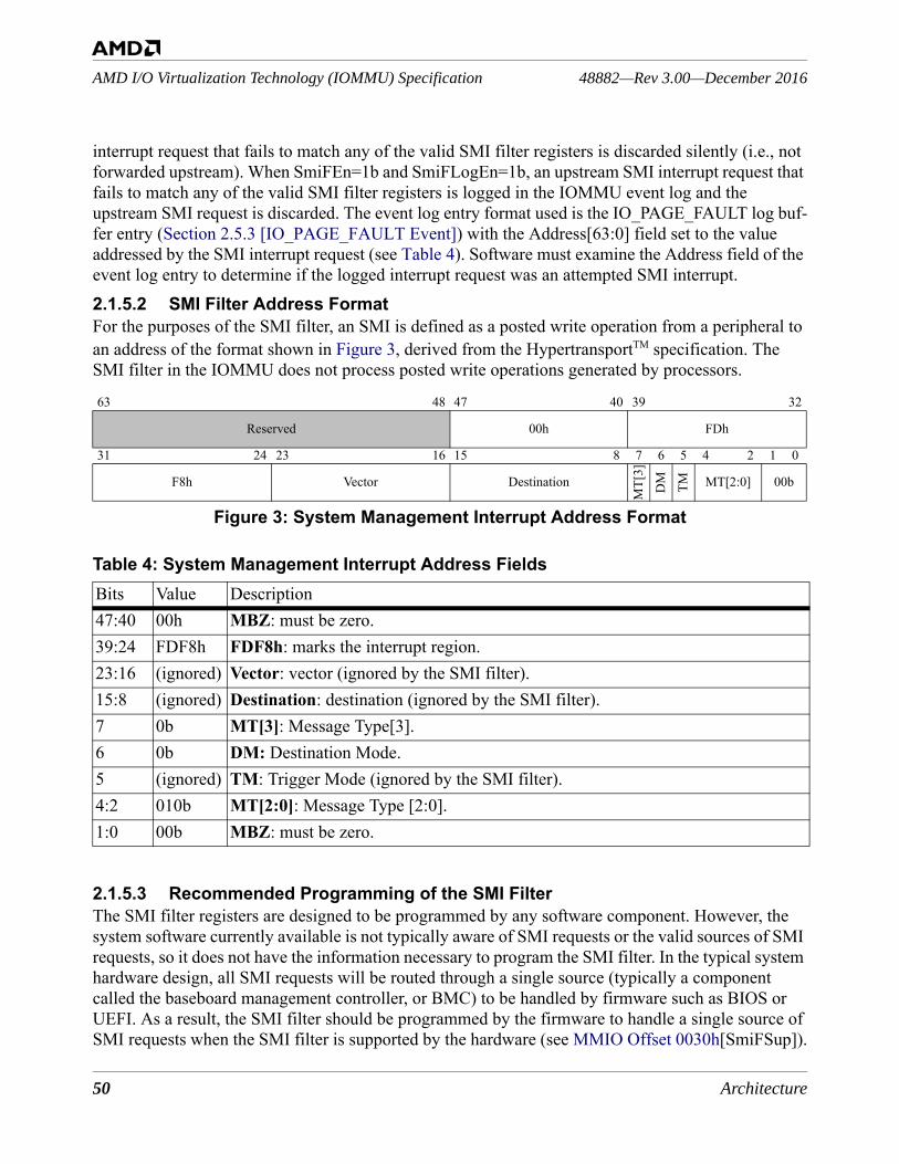
50 Architecture
48882—Rev 3.00—December 2016AMD I/O Virtualization Technology (IOMMU) Specification
interrupt request that fails to match any of the valid SMI filter registers is discarded silently (i.e., not forwarded upstream). When SmiFEn=1b and SmiFLogEn=1b, an upstream SMI interrupt request that fails to match any of the valid SMI filter registers is logged in the IOMMU event log and the upstream SMI request is discarded. The event log entry format used is the IO_PAGE_FAULT log buf-fer entry (Section 2.5.3 [IO_PAGE_FAULT Event]) with the Address[63:0] field set to the value addressed by the SMI interrupt request (see Table 4). Software must examine the Address field of the event log entry to determine if the logged interrupt request was an attempted SMI interrupt.2.1.5.2 SMI Filter Address FormatFor the purposes of the SMI filter, an SMI is defined as a posted write operation from a peripheral to an address of the format shown in Figure 3, derived from the HypertransportTM specification. The SMI filter in the IOMMU does not process posted write operations generated by processors.
Figure 3: System Management Interrupt Address Format
2.1.5.3 Recommended Programming of the SMI FilterThe SMI filter registers are designed to be programmed by any software component. However, the system software currently available is not typically aware of SMI requests or the valid sources of SMI requests, so it does not have the information necessary to program the SMI filter. In the typical system hardware design, all SMI requests will be routed through a single source (typically a component called the baseboard management controller, or BMC) to be handled by firmware such as BIOS or UEFI. As a result, the SMI filter should be programmed by the firmware to handle a single source of SMI requests when the SMI filter is supported by the hardware (see MMIO Offset 0030h[SmiFSup]).
63 48 47 40 39 32
Reserved 00h FDh
31 24 23 16 15 8 7 6 5 4 2 1 0
F8h Vector Destination
MT[
3]
DM TM MT[2:0] 00b
Table 4: System Management Interrupt Address FieldsBits Value Description47:40 00h MBZ: must be zero.39:24 FDF8h FDF8h: marks the interrupt region.23:16 (ignored) Vector: vector (ignored by the SMI filter).15:8 (ignored) Destination: destination (ignored by the SMI filter).7 0b MT[3]: Message Type[3].6 0b DM: Destination Mode.5 (ignored) TM: Trigger Mode (ignored by the SMI filter).4:2 010b MT[2:0]: Message Type [2:0].1:0 00b MBZ: must be zero.
Architecture 51
AMD I/O Virtualization Technology (IOMMU) Specification48882—Rev 3.00—December 2016
The recommended method to program the SMI filter is:1. check that the SMI filter is supported (see MMIO Offset 0030h[SmiFSup]),2. choose an SMI filter register to use from the available set (see MMIO Offset 0030h[SmiFRC]),3. program the selected SMI filter register to the DeviceID of the BMC (see MMIO Offset 00[60-
D8]h[SmiDID]), 4. program the selected SMI filter register to be valid (see MMIO Offset 00[60-D8]h[SmiDV]), 5. program the selected SMI filter register to be locked (see MMIO Offset 00[60-D8]h[SmiFLock]),6. program any remaining SMI filter registers to be not-valid and locked, and7. program MMIO Offset 0018h[SmiFLogEn] to disable SMI logging.
If the system software that processes the IOMMU event log is aware of the SMI filter, MMIO Offset 0018h[SmiFLogEn] should instead be programmed to enable SMI logging.The more general case of programming the SMI filter registers is discussed in the following section.
2.1.5.4 General Programming of the SMI Filter RegistersWhen the IOMMU is reset, software must program the registers to make the SMI filter active. The optional SMI filter is implemented when MMIO Offset 0030h[SmiFSup] = 01b and enabled when software programs MMIO Offset 0018h[SmiFEn] = 1b. The SMI filter registers work as a set and the number of SMI filter registers implemented by an IOMMU is reported in MMIO Offset 0030h[Smi-FRC] (see also Table 68). Each SMI filter register contains three fields: SmiDV, SmiDID, and Smi-FLock (see IOMMU SMI Filter Register [MMIO Offset 00[60-D8]h]). The values of SmiDID and SmiDV are read-only when SmiFLock = 1b and are read-write when Smi-FLock = 0b. An SMI filter register containing SmiDV = 0b is inactive (never matches) and may be activated by programming SmiDV = 1b when SmiFLock = 0b; the entire SMI filter register may be programmed in one operation (i.e., software may set SmiDID, SmiDV = 1b and SmiFLock = 1b in the same operation). Software may lock an SMI filter register to be inactive by programming SmiDV = 0b and SmiFLock = 1b. Software may lock a value into an SMI filter register by programming Smi-DID and SmiDV to the desired values and SmiFLock = 1b. Once locked, an SMI filter register can only be changed after a system reset sets SmiFLock = 0b.An entry describing the blocked SMI interrupt request is optionally recorded in the IOMMU event log (see MMIO Offset 0018h[SmiFLogEn]). When logging is enabled, software can monitor the log entries to detect if excessive SMI interrupts are being received from an unexpected source device (DeviceID). When it detects excessive SMI interrupts, software can turn off the logging to reduce processing overhead. After software throttles or stops the source of the unexpected SMI interrupts, software can program MMIO Offset 0018h[SmiFLogEn] to resume the creation of event log notifica-tions for SMI interrupts blocked by the SMI filter. The DTE and IRTE fields SA, SE, IG, and SupI-OPF do not affect logging of events from the SMI filter (see Table 7 and Table 20).To freeze a particular configuration of SMI filtering, program the SmiFLock=1b in each implemented SMI filter register.
52 Architecture
48882—Rev 3.00—December 2016AMD I/O Virtualization Technology (IOMMU) Specification
System software that is not aware of SMI requests or the valid sources of SMI requests does not have the information necessary to program the SMI filter and the recommended programming procedure is described in Section 2.1.5.3 [Recommended Programming of the SMI Filter]. In a more general system design, SMI requests may originate from multiple sources that are not lim-ited to the baseboard management controller (BMC). The SMI filter can be programmed by the BIOS or UEFI to allow multiple sources of SMI requests when the SMI filter is supported by the hardware (see MMIO Offset 0030h[SmiFSup]). The procedure for this case is to:1. check that the SMI filter is supported (see MMIO Offset 0030h[SmiFSup]),2. for each expected source of SMI requests:
• choose an SMI filter register to use from the available set (see MMIO Offset 0030h[SmiFRC]),
• program the selected SMI filter register to the DeviceID of the peripheral (see MMIO Offset 00[60-D8]h[SmiDID]),
• program the selected SMI filter register to be valid (see MMIO Offset 00[60-D8]h[SmiDV]), • program the selected SMI filter register to be locked (see MMIO Offset 00[60-
D8]h[SmiFLock]),3. reserve one or more of the remaining SMI filter registers to be unprogrammed and unlocked for
use by the system software,4. program remaining SMI filter registers not reserved for use by system software to be not-valid
and locked,5. program MMIO Offset 0018h[SmiFLogEn] to enable SMI logging so that system software is
informed of SMI requests blocked by the SMI filter.
In this configuration, system software may program the unlocked SMI filter registers to allow SMI requests from additional peripherals. Software should be aware that once an SMI filter register is locked, it cannot be reprogrammed until the system is reset. System software and firmware will need to coordinate use of SMI filter registers using a method that is outside the scope this document.
2.2 Data StructuresHost software must maintain up to eight in-memory data structures for use by the IOMMU. These data structures are:1. The Device Table is a table indexed by DeviceIDs. Each Device Table entry contains mode bits, a
pointer to the I/O page tables, a pointer to an interrupt remapping control table, a set of control bits, and a 16-bit DomainID. The DomainID acts as an address space identifier, allowing multiple devices sharing the same I/O page tables to share the same translation cache resources on the IOMMU. The page tables must be the same for all devices that share a DomainID.
2. The I/O page table(s): Each Device Table entry may specify a different I/O page table, or different Device Table entries may share the same I/O page tables. Each time the IOMMU processes a device access to memory, it looks up the device virtual address (DVA) in its translation cache and/or the appropriate I/O page tables to determine whether the device has permission, as well as (if permitted) the system physical address to access.
Architecture 53
AMD I/O Virtualization Technology (IOMMU) Specification48882—Rev 3.00—December 2016
3. The command buffer: The IOMMU accepts commands queued by the processor through a circu-lar buffer located in system memory.
4. The event log: The IOMMU reports atypical events to the processor by means of another circular buffer, the event log, located in system memory.
5. The interrupt remapping table(s): Each Device Table entry may specify an interrupt remapping table. Each time the IOMMU processes a device interrupt request, it looks up the IRTE to remap the interrupt to the destination with a translated vector. (See Figure 15 on page 83 and Table 20 on page 83)
6. The peripheral page request log: The IOMMU can accept requests from PRI-capable peripherals to service page change requests. These requests are reported in a circular buffer, the PPR log, located in system memory.
7. The guest virtual APIC tables: The IOMMU can update guest interrupt request status.8. The guest virtual APIC log: The IOMMU can report guest virtual interrupts sent to a guest that is
not running.
Figure 4 illustrates the relationships among the IOMMU data structures. Figure elements with dashed borders are optional.

54 Architecture
48882—Rev 3.00—December 2016AMD I/O Virtualization Technology (IOMMU) Specification
Figure 4: IOMMU Data Structures The base funtionality of the IOMMU supports one-level translation tables for address translation and for interrupt remapping. The event log is the only data structures in system memory that is written by the IOMMU. The maximum size of a virtual address (GPA) is defined in Capability Offset 10h[VAsize] and the maximum size of a physical address (SPA) is defined in Capability Offset 10h[PAsize].The IOMMU optionally supports both one-level and two-level translation tables (Table 5) as well as guest APIC virtualization, hardware error registers, performance counter registers, peripheral page-request services, and an SMI filter. An IOMMU can write to the event log, the peripheral page request
dna
mmo
Cre
ffuB
tnev
Ego
L
IOMMU
I/O page tableseciv
eD
elba
T
Device Table Base
register
System memory
Command Buffer base
registerEvent Log
base register
tpurr
etnI
gnip
pame
Rel
baT
Hosttranslation
eci
vreS
ega
Pgo
L tse
uqe
R
Page Req Log base register
Event Counter registers
GCR3 table
IRT
IRT
VirtualAPIC
Hardware Error
registers
lautr
iV t
seu
Ggo
L CI
PA
Guest Virtual
APIC Log
SMI Filter registers
Guesttranslation
Hosttranslation
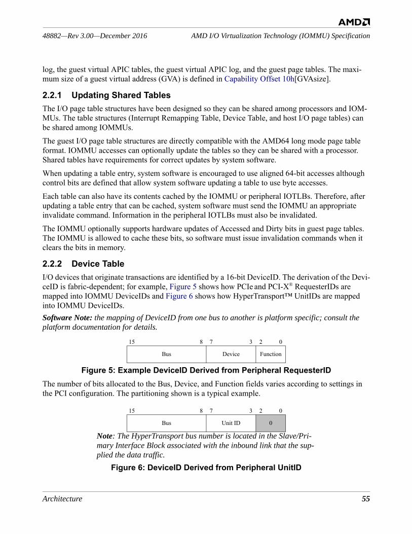
Architecture 55
AMD I/O Virtualization Technology (IOMMU) Specification48882—Rev 3.00—December 2016
log, the guest virtual APIC tables, the guest virtual APIC log, and the guest page tables. The maxi-mum size of a guest virtual address (GVA) is defined in Capability Offset 10h[GVAsize].
2.2.1 Updating Shared TablesThe I/O page table structures have been designed so they can be shared among processors and IOM-MUs. The table structures (Interrupt Remapping Table, Device Table, and host I/O page tables) can be shared among IOMMUs. The guest I/O page table structures are directly compatible with the AMD64 long mode page table format. IOMMU accesses can optionally update the tables so they can be shared with a processor. Shared tables have requirements for correct updates by system software.When updating a table entry, system software is encouraged to use aligned 64-bit accesses although control bits are defined that allow system software updating a table to use byte accesses.Each table can also have its contents cached by the IOMMU or peripheral IOTLBs. Therefore, after updating a table entry that can be cached, system software must send the IOMMU an appropriate invalidate command. Information in the peripheral IOTLBs must also be invalidated. The IOMMU optionally supports hardware updates of Accessed and Dirty bits in guest page tables. The IOMMU is allowed to cache these bits, so software must issue invalidation commands when it clears the bits in memory.
2.2.2 Device TableI/O devices that originate transactions are identified by a 16-bit DeviceID. The derivation of the Devi-ceID is fabric-dependent; for example, Figure 5 shows how PCIe and PCI-X® RequesterIDs are mapped into IOMMU DeviceIDs and Figure 6 shows how HyperTransport™ UnitIDs are mapped into IOMMU DeviceIDs. Software Note: the mapping of DeviceID from one bus to another is platform specific; consult the platform documentation for details.
Figure 5: Example DeviceID Derived from Peripheral RequesterIDThe number of bits allocated to the Bus, Device, and Function fields varies according to settings in the PCI configuration. The partitioning shown is a typical example.
Figure 6: DeviceID Derived from Peripheral UnitID
15 8 7 3 2 0
Bus Device Function
15 8 7 3 2 0
Bus Unit ID 0
Note: The HyperTransport bus number is located in the Slave/Pri-mary Interface Block associated with the inbound link that the sup-plied the data traffic.
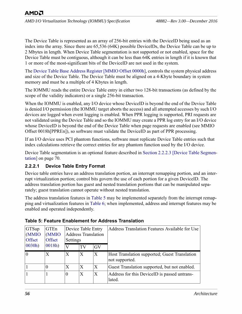
56 Architecture
48882—Rev 3.00—December 2016AMD I/O Virtualization Technology (IOMMU) Specification
The Device Table is represented as an array of 256-bit entries with the DeviceID being used as an index into the array. Since there are 65,536 (64K) possible DeviceIDs, the Device Table can be up to 2 Mbytes in length. When Device Table segmentation is not supported or not enabled, space for the Device Table must be contiguous, although it can be less than 64K entries in length if it is known that 1 or more of the most-significant bits of the DeviceID are not used in the system.The Device Table Base Address Register [MMIO Offset 0000h], controls the system physical address and size of the Device Table. The Device Table must be aligned on a 4-Kbyte boundary in system memory and must be a multiple of 4 Kbytes in length. The IOMMU reads the entire Device Table entry in either two 128-bit transactions (as defined by the scope of the validity indicators) or a single 256-bit transaction.When the IOMMU is enabled, any I/O device whose DeviceID is beyond the end of the Device Table is denied I/O permission (the IOMMU target aborts the access) and all attempted accesses by such I/O devices are logged when event logging is enabled. When PPR logging is supported, PRI requests are not validated using the Device Table and so the IOMMU may create a PPR log entry for an I/O device whose DeviceID is beyond the end of the Device Table when page requests are enabled (see MMIO Offset 0018h[PPREn]), so software must validate the DeviceID as part of PPR processing.If an I/O device uses PCI phantom functions, software must replicate Device Table entries such that index calculations retrieve the correct entries for any phantom function used by the I/O device.Device Table segmentation is an optional feature described in Section 2.2.2.3 [Device Table Segmen-tation] on page 70.2.2.2.1 Device Table Entry FormatDevice table entries have an address translation portion, an interrupt remapping portion, and an inter-rupt virtualization portion; control bits govern the use of each portion for a given DeviceID. The address translation portion has guest and nested translation portions that can be manipulated sepa-rately; guest translation cannot operate without nested translation. The address translation features in Table 5 may be implemented separately from the interrupt remap-ping and virtualization features in Table 6; when implemented, address and interrupt features may be enabled and operated independently.
Table 5: Feature Enablement for Address TranslationGTSup(MMIO Offset 0030h)
GTEn(MMIO Offset 0018h)
Device Table Entry Address Translation Settings
Address Translation Features Available for Use
V TV GV0 X X X X Host Translation supported; Guest Translation
not supported.1 0 X X X Guest Translation supported, but not enabled.1 1 0 X X Address for this DeviceID is passed untrans-
lated.
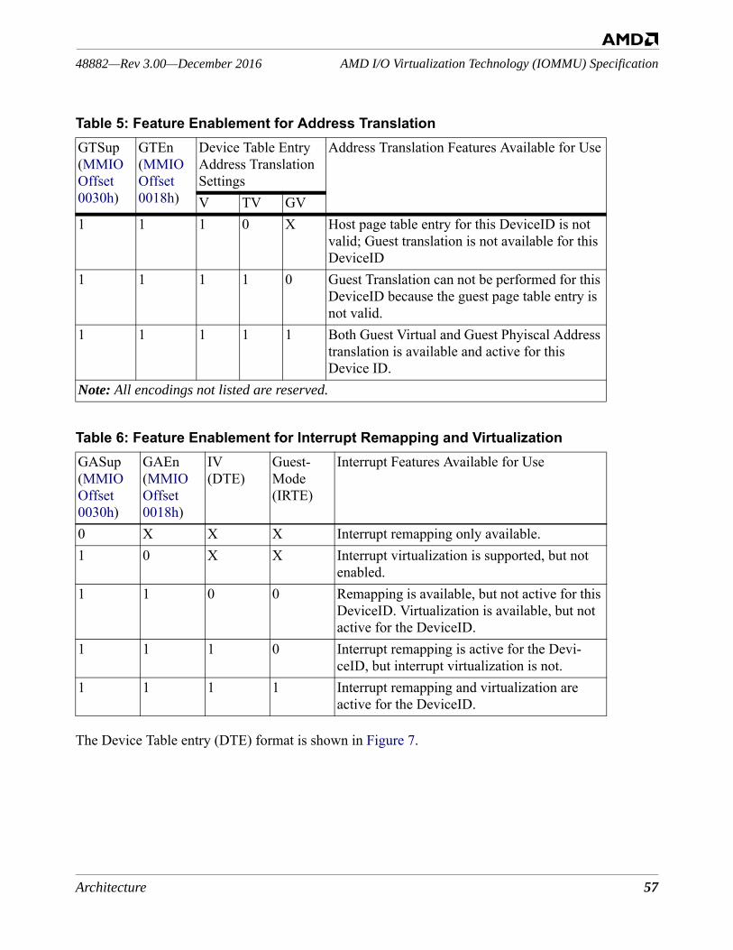
Architecture 57
AMD I/O Virtualization Technology (IOMMU) Specification48882—Rev 3.00—December 2016
The Device Table entry (DTE) format is shown in Figure 7.
1 1 1 0 X Host page table entry for this DeviceID is not valid; Guest translation is not available for this DeviceID
1 1 1 1 0 Guest Translation can not be performed for this DeviceID because the guest page table entry is not valid.
1 1 1 1 1 Both Guest Virtual and Guest Phyiscal Address translation is available and active for this Device ID.
Note: All encodings not listed are reserved.
Table 6: Feature Enablement for Interrupt Remapping and VirtualizationGASup(MMIO Offset 0030h)
GAEn(MMIO Offset 0018h)
IV (DTE)
Guest-Mode (IRTE)
Interrupt Features Available for Use
0 X X X Interrupt remapping only available.1 0 X X Interrupt virtualization is supported, but not
enabled.1 1 0 0 Remapping is available, but not active for this
DeviceID. Virtualization is available, but not active for the DeviceID.
1 1 1 0 Interrupt remapping is active for the Devi-ceID, but interrupt virtualization is not.
1 1 1 1 Interrupt remapping and virtualization are active for the DeviceID.
Table 5: Feature Enablement for Address TranslationGTSup(MMIO Offset 0030h)
GTEn(MMIO Offset 0018h)
Device Table Entry Address Translation Settings
Address Translation Features Available for Use
V TV GV
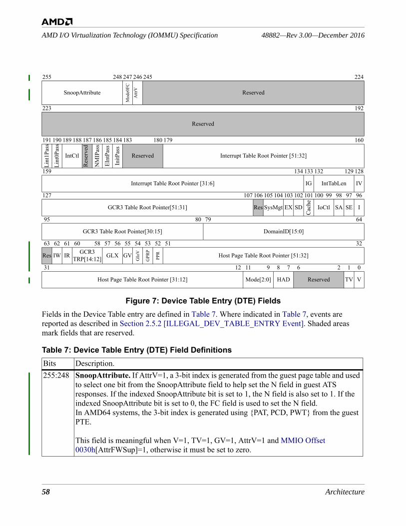
58 Architecture
48882—Rev 3.00—December 2016AMD I/O Virtualization Technology (IOMMU) Specification
Figure 7: Device Table Entry (DTE) FieldsFields in the Device Table entry are defined in Table 7. Where indicated in Table 7, events are reported as described in Section 2.5.2 [ILLEGAL_DEV_TABLE_ENTRY Event]. Shaded areas mark fields that are reserved.
255 248 247 246 245 224
SnoopAttribute
Mod
e0FC
Attr
V Reserved
223 192
Reserved
191 190 189 188 187 186 185 184 183 180 179 160
Lint
1Pas
s
Lint
0Pas
s
IntCtl
Rese
rved
NM
IPas
s
EInt
Pass
InitP
ass
Reserved Interrupt Table Root Pointer [51:32]
159 134 133 132 129 128
Interrupt Table Root Pointer [31:6] IG IntTabLen IV
127 107 106 105 104 103 102 101 100 99 98 97 96
GCR3 Table Root Pointer[51:31] Res SysMgt EX SD
Cach
e
IoCtl SA SE I
95 80 79 64
GCR3 Table Root Pointer[30:15] DomainID[15:0]
63 62 61 60 58 57 56 55 54 53 52 51 32
Res IW IR GCR3 TRP[14:12] GLX GV
GIo
V
GPR
P
PPR Host Page Table Root Pointer [51:32]
31 12 11 9 8 7 6 2 1 0
Host Page Table Root Pointer [31:12] Mode[2:0] HAD Reserved TV V
Table 7: Device Table Entry (DTE) Field DefinitionsBits Description.255:248 SnoopAttribute. If AttrV=1, a 3-bit index is generated from the guest page table and used
to select one bit from the SnoopAttribute field to help set the N field in guest ATS responses. If the indexed SnoopAttribute bit is set to 1, the N field is also set to 1. If the indexed SnoopAttribute bit is set to 0, the FC field is used to set the N field.In AMD64 systems, the 3-bit index is generated using {PAT, PCD, PWT} from the guest PTE.
This field is meaningful when V=1, TV=1, GV=1, AttrV=1 and MMIO Offset 0030h[AttrFWSup]=1, otherwise it must be set to zero.
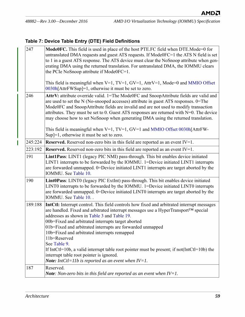
Architecture 59
AMD I/O Virtualization Technology (IOMMU) Specification48882—Rev 3.00—December 2016
247 Mode0FC. This field is used in place of the host PTE.FC field when DTE.Mode=0 for untranslated DMA requests and guest ATS requests. If Mode0FC=1 the ATS N field is set to 1 in a guest ATS response. The ATS device must clear the NoSnoop attribute when gen-erating DMA using the returned translation. For untranslated DMA, the IOMMU clears the PCIe NoSnoop attribute if Mode0FC=1.
This field is meaningful when V=1, TV=1, GV=1, AttrV=1, Mode=0 and MMIO Offset 0030h[AttrFWSup]=1, otherwise it must be set to zero.
246 AttrV: attribute override valid. 1=The Mode0FC and SnoopAttribute fields are valid and are used to set the N (No-snooped accesses) attribute in guest ATS responses. 0=The Mode0FC and SnoopAttribute fields are invalid and are not used to modify transaction attributes. They must be set to 0. Guest ATS responses are returned with N=0. The device may choose how to set NoSnoop when generating DMA using the returned translation.
This field is meaningful when V=1, TV=1, GV=1 and MMIO Offset 0030h[AttrFW-Sup]=1, otherwise it must be set to zero.
245:224 Reserved. Reserved non-zero bits in this field are reported as an event IV=1.223:192 Reserved. Reserved non-zero bits in this field are reported as an event IV=1.191 Lint1Pass: LINT1 (legacy PIC NMI) pass-through. This bit enables device initiated
LINT1 interrupts to be forwarded by the IOMMU. 1=Device initiated LINT1 interrupts are forwarded unmapped. 0=Device initiated LINT1 interrupts are target aborted by the IOMMU. See Table 10.
190 Lint0Pass: LINT0 (legacy PIC ExtInt) pass-through. This bit enables device initiated LINT0 interrupts to be forwarded by the IOMMU. 1=Device initiated LINT0 interrupts are forwarded unmapped. 0=Device initiated LINT0 interrupts are target aborted by the IOMMU. See Table 10. .
189:188 IntCtl: Interrupt control. This field controls how fixed and arbitrated interrupt messages are handled. Fixed and arbitrated interrupt messages use a HyperTransport™ special addresses as shown in Table 3 and Table 19. 00b=Fixed and arbitrated interrupts target aborted 01b=Fixed and arbitrated interrupts are forwarded unmapped10b=Fixed and arbitrated interrupts remapped 11b=ReservedSee Table 9.If IntCtl=10b, a valid interrupt table root pointer must be present; if not(IntCtl=10b) the interrupt table root pointer is ignored.Note: IntCtl=11b is reported as an event when IV=1.
187 Reserved.Note: Non-zero bits in this field are reported as an event when IV=1.
Table 7: Device Table Entry (DTE) Field Definitions
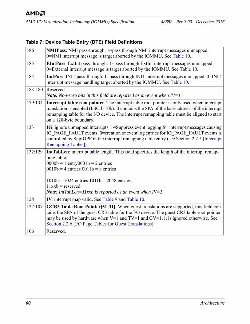
60 Architecture
48882—Rev 3.00—December 2016AMD I/O Virtualization Technology (IOMMU) Specification
186 NMIPass: NMI pass-through. 1=pass through NMI interrupt messages unmapped. 0=NMI interrupt message is target aborted by the IOMMU. See Table 10.
185 EIntPass: ExtInt pass-through. 1=pass through ExtInt interrupt messages unmapped. 0=External interrupt message is target aborted by the IOMMU. See Table 10.
184 InitPass: INIT pass-through. 1=pass through INIT interrupt messages unmapped. 0=INIT interrupt message handling target aborted by the IOMMU. See Table 10.
183-180 Reserved.Note: Non-zero bits in this field are reported as an event when IV=1.
179:134 Interrupt table root pointer. The interrupt table root pointer is only used when interrupt translation is enabled (IntCtl=10b). It contains the SPA of the base address of the interrupt remapping table for the I/O device. The interrupt remapping table must be aligned to start on a 128-byte boundary.
133 IG: ignore unmapped interrupts. 1=Suppress event logging for interrupt messages causing IO_PAGE_FAULT events. 0=creation of event log entries for IO_PAGE_FAULT events is controlled by SupIOPF in the interrupt remapping table entry (see Section 2.2.5 [Interrupt Remapping Tables]).
132:129 IntTabLen: interrupt table length. This field specifies the length of the interrupt remap-ping table. 0000b = 1 entry0001b = 2 entries0010b = 4 entries 0011b = 8 entries...1010b = 1024 entries 1011b = 2048 entries11xxb = reservedNote: IntTabLen=11xxb is reported as an event when IV=1.
128 IV: interrupt map valid. See Table 9 and Table 10. 127:107 GCR3 Table Root Pointer[51:31]. When guest translations are supported, this field con-
tains the SPA of the guest CR3 table for the I/O device. The guest CR3 table root pointer may be used by hardware when V=1 and TV=1 and GV=1; it is ignored otherwise. See Section 2.2.6 [I/O Page Tables for Guest Translations].
106 Reserved.
Table 7: Device Table Entry (DTE) Field Definitions
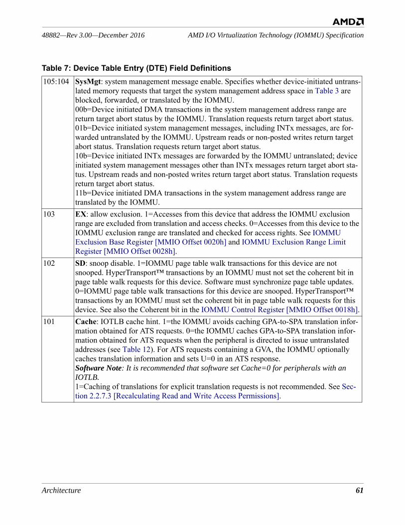
Architecture 61
AMD I/O Virtualization Technology (IOMMU) Specification48882—Rev 3.00—December 2016
105:104 SysMgt: system management message enable. Specifies whether device-initiated untrans-lated memory requests that target the system management address space in Table 3 are blocked, forwarded, or translated by the IOMMU. 00b=Device initiated DMA transactions in the system management address range are return target abort status by the IOMMU. Translation requests return target abort status.01b=Device initiated system management messages, including INTx messages, are for-warded untranslated by the IOMMU. Upstream reads or non-posted writes return target abort status. Translation requests return target abort status.10b=Device initiated INTx messages are forwarded by the IOMMU untranslated; device initiated system management messages other than INTx messages return target abort sta-tus. Upstream reads and non-posted writes return target abort status. Translation requests return target abort status.11b=Device initiated DMA transactions in the system management address range are translated by the IOMMU.
103 EX: allow exclusion. 1=Accesses from this device that address the IOMMU exclusion range are excluded from translation and access checks. 0=Accesses from this device to the IOMMU exclusion range are translated and checked for access rights. See IOMMU Exclusion Base Register [MMIO Offset 0020h] and IOMMU Exclusion Range Limit Register [MMIO Offset 0028h].
102 SD: snoop disable. 1=IOMMU page table walk transactions for this device are not snooped. HyperTransport™ transactions by an IOMMU must not set the coherent bit in page table walk requests for this device. Software must synchronize page table updates. 0=IOMMU page table walk transactions for this device are snooped. HyperTransport™ transactions by an IOMMU must set the coherent bit in page table walk requests for this device. See also the Coherent bit in the IOMMU Control Register [MMIO Offset 0018h].
101 Cache: IOTLB cache hint. 1=the IOMMU avoids caching GPA-to-SPA translation infor-mation obtained for ATS requests. 0=the IOMMU caches GPA-to-SPA translation infor-mation obtained for ATS requests when the peripheral is directed to issue untranslated addresses (see Table 12). For ATS requests containing a GVA, the IOMMU optionally caches translation information and sets U=0 in an ATS response. Software Note: It is recommended that software set Cache=0 for peripherals with an IOTLB.1=Caching of translations for explicit translation requests is not recommended. See Sec-tion 2.2.7.3 [Recalculating Read and Write Access Permissions].
Table 7: Device Table Entry (DTE) Field Definitions
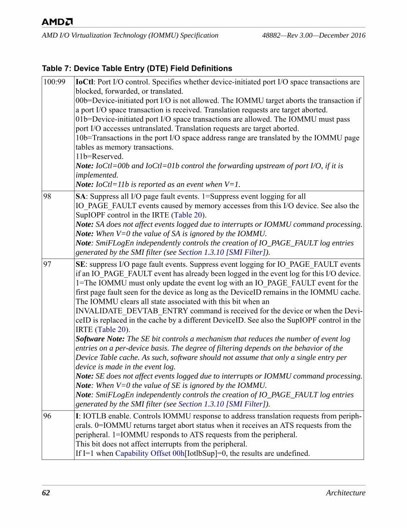
62 Architecture
48882—Rev 3.00—December 2016AMD I/O Virtualization Technology (IOMMU) Specification
100:99 IoCtl: Port I/O control. Specifies whether device-initiated port I/O space transactions are blocked, forwarded, or translated. 00b=Device-initiated port I/O is not allowed. The IOMMU target aborts the transaction if a port I/O space transaction is received. Translation requests are target aborted. 01b=Device-initiated port I/O space transactions are allowed. The IOMMU must pass port I/O accesses untranslated. Translation requests are target aborted.10b=Transactions in the port I/O space address range are translated by the IOMMU page tables as memory transactions.11b=Reserved.Note: IoCtl=00b and IoCtl=01b control the forwarding upstream of port I/O, if it is implemented.Note: IoCtl=11b is reported as an event when V=1.
98 SA: Suppress all I/O page fault events. 1=Suppress event logging for all IO_PAGE_FAULT events caused by memory accesses from this I/O device. See also the SupIOPF control in the IRTE (Table 20).Note: SA does not affect events logged due to interrupts or IOMMU command processing.Note: When V=0 the value of SA is ignored by the IOMMU.Note: SmiFLogEn independently controls the creation of IO_PAGE_FAULT log entries generated by the SMI filter (see Section 1.3.10 [SMI Filter]).
97 SE: suppress I/O page fault events. Suppress event logging for IO_PAGE_FAULT events if an IO_PAGE_FAULT event has already been logged in the event log for this I/O device. 1=The IOMMU must only update the event log with an IO_PAGE_FAULT event for the first page fault seen for the device as long as the DeviceID remains in the IOMMU cache. The IOMMU clears all state associated with this bit when an INVALIDATE_DEVTAB_ENTRY command is received for the device or when the Devi-ceID is replaced in the cache by a different DeviceID. See also the SupIOPF control in the IRTE (Table 20).Software Note: The SE bit controls a mechanism that reduces the number of event log entries on a per-device basis. The degree of filtering depends on the behavior of the Device Table cache. As such, software should not assume that only a single entry per device is made in the event log.Note: SE does not affect events logged due to interrupts or IOMMU command processing.Note: When V=0 the value of SE is ignored by the IOMMU.Note: SmiFLogEn independently controls the creation of IO_PAGE_FAULT log entries generated by the SMI filter (see Section 1.3.10 [SMI Filter]).
96 I: IOTLB enable. Controls IOMMU response to address translation requests from periph-erals. 0=IOMMU returns target abort status when it receives an ATS requests from the peripheral. 1=IOMMU responds to ATS requests from the peripheral.This bit does not affect interrupts from the peripheral. If I=1 when Capability Offset 00h[IotlbSup]=0, the results are undefined.
Table 7: Device Table Entry (DTE) Field Definitions

Architecture 63
AMD I/O Virtualization Technology (IOMMU) Specification48882—Rev 3.00—December 2016
95:80 GCR3 Table Root Pointer[30:15]. When guest translations are supported, this field con-tains the SPA of the top (or only) level of the guest CR3 table for the peripheral. The guest CR3 table root pointer may be used by hardware when V=1 and TV=1 and GV=1. See Section 2.2.6 [I/O Page Tables for Guest Translations]. Must be zero when MMIO Offset 0030h[GTSup]=0.
79:64 DomainID. The DomainID is a 16-bit integer chosen by software that the IOMMU must use to tag its internal translation caches and to mark event log entries. I/O devices with different page tables must be given different DomainIDs. I/O devices that share the same page tables may be given the same DomainID. I/O devices that share the same DTE[DomainID] must have the same settings in the DTE[Mode] and page table root pointer fields, however they may have different values in the DTE[I] and DTE[SysMgt] fields. If devices with the same DTE[DomainID] are given different non-zero values in the DTE[Mode] field or different page table root pointer values, the behavior of the IOMMU is undefined. The value of the DTE[DomainID] recorded in an event log entry is undefined when V=0 and IV=1.
63 Reserved.Note: A non-zero value in this field is reported as an event when V=1.
62 IW: I/O write permission. Used in the calculation of effective write access with the per-mission bits in the page tables; if there are no page tables (DTE[Mode]=000b), then this bit defines the I/O write permission. 1=I/O device is allowed to perform DMA write trans-actions and 0-byte read transactions (see Section 2.1.4 [Special Conditions]); the I/O device is allowed to perform DMA atomic operations when IR is also programmed to allow read access. 0=Device initiated DMA write and atomic transactions are target aborted.
61 IR: I/O read permission. Used in the calculation of effective read access with the permis-sion bits in the page tables; if there are no page tables (DTE[Mode]=000b), then this bit defines the I/O read permission. 1=I/O device is allowed to perform DMA read transac-tions; the I/O device is allowed to perform atomic transactions when IW is also pro-grammed to allow write operations. 0=Device initiated DMA read transactions are target aborted. When both IW and IW are programmed to 0b, device-initiated 0-byte read trans-actions are target aborted.
60:58 GCR3 TRP: guest CR3 table root pointer[14:12]. When guest translations are supported, this field contains the SPA of the top (or only) level of the guest CR3 table for the I/O device. The guest CR3 table root pointer may be used by hardware when V=1 and TV=1 and GV=1. See Section 2.2.6 [I/O Page Tables for Guest Translations]. Must be zero when MMIO Offset 0030h[GTSup]=0.
Table 7: Device Table Entry (DTE) Field Definitions
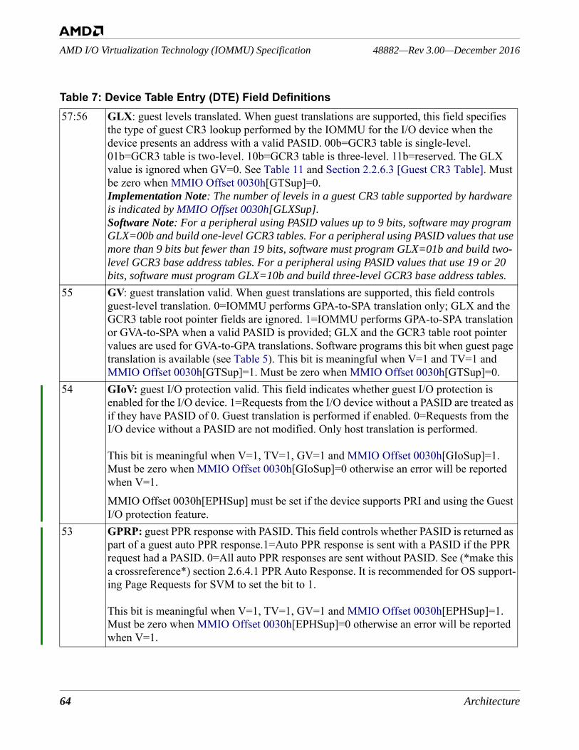
64 Architecture
48882—Rev 3.00—December 2016AMD I/O Virtualization Technology (IOMMU) Specification
57:56 GLX: guest levels translated. When guest translations are supported, this field specifies the type of guest CR3 lookup performed by the IOMMU for the I/O device when the device presents an address with a valid PASID. 00b=GCR3 table is single-level. 01b=GCR3 table is two-level. 10b=GCR3 table is three-level. 11b=reserved. The GLX value is ignored when GV=0. See Table 11 and Section 2.2.6.3 [Guest CR3 Table]. Must be zero when MMIO Offset 0030h[GTSup]=0.Implementation Note: The number of levels in a guest CR3 table supported by hardware is indicated by MMIO Offset 0030h[GLXSup].Software Note: For a peripheral using PASID values up to 9 bits, software may program GLX=00b and build one-level GCR3 tables. For a peripheral using PASID values that use more than 9 bits but fewer than 19 bits, software must program GLX=01b and build two-level GCR3 base address tables. For a peripheral using PASID values that use 19 or 20 bits, software must program GLX=10b and build three-level GCR3 base address tables.
55 GV: guest translation valid. When guest translations are supported, this field controls guest-level translation. 0=IOMMU performs GPA-to-SPA translation only; GLX and the GCR3 table root pointer fields are ignored. 1=IOMMU performs GPA-to-SPA translation or GVA-to-SPA when a valid PASID is provided; GLX and the GCR3 table root pointer values are used for GVA-to-GPA translations. Software programs this bit when guest page translation is available (see Table 5). This bit is meaningful when V=1 and TV=1 and MMIO Offset 0030h[GTSup]=1. Must be zero when MMIO Offset 0030h[GTSup]=0.
54 GIoV: guest I/O protection valid. This field indicates whether guest I/O protection is enabled for the I/O device. 1=Requests from the I/O device without a PASID are treated as if they have PASID of 0. Guest translation is performed if enabled. 0=Requests from the I/O device without a PASID are not modified. Only host translation is performed.
This bit is meaningful when V=1, TV=1, GV=1 and MMIO Offset 0030h[GIoSup]=1. Must be zero when MMIO Offset 0030h[GIoSup]=0 otherwise an error will be reported when V=1.MMIO Offset 0030h[EPHSup] must be set if the device supports PRI and using the Guest I/O protection feature.
53 GPRP: guest PPR response with PASID. This field controls whether PASID is returned as part of a guest auto PPR response.1=Auto PPR response is sent with a PASID if the PPR request had a PASID. 0=All auto PPR responses are sent without PASID. See (*make this a crossreference*) section 2.6.4.1 PPR Auto Response. It is recommended for OS support-ing Page Requests for SVM to set the bit to 1.
This bit is meaningful when V=1, TV=1, GV=1 and MMIO Offset 0030h[EPHSup]=1. Must be zero when MMIO Offset 0030h[EPHSup]=0 otherwise an error will be reported when V=1.
Table 7: Device Table Entry (DTE) Field Definitions
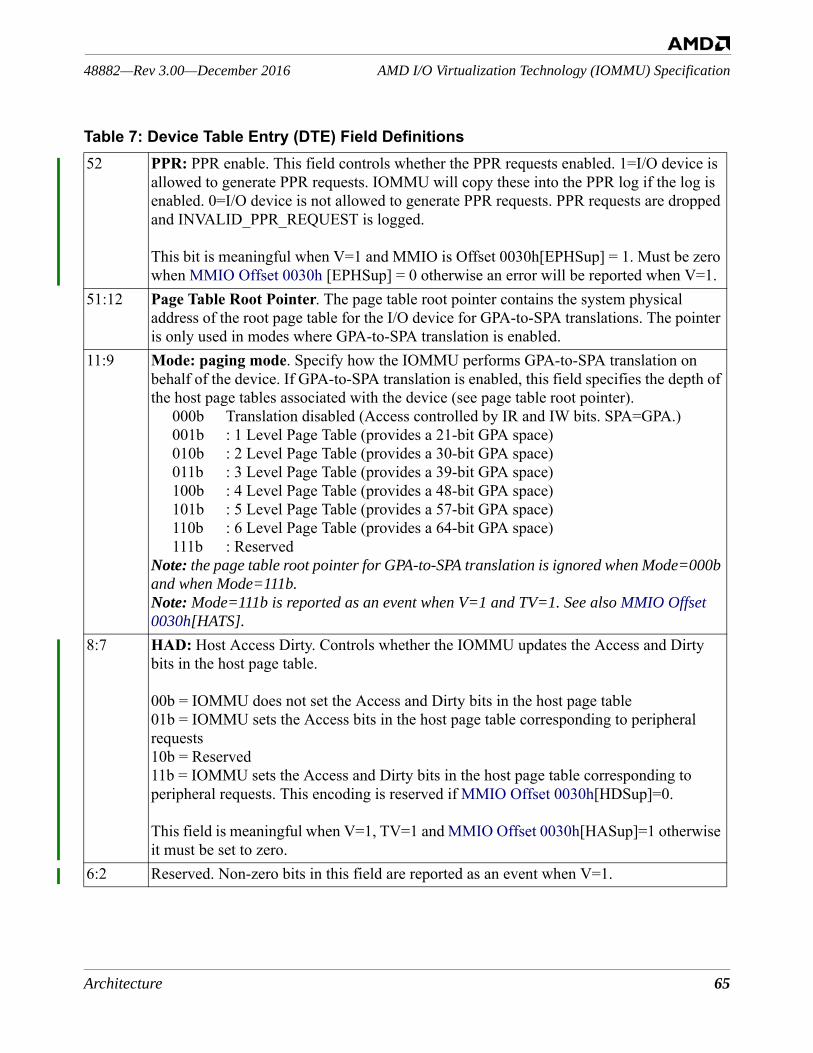
Architecture 65
AMD I/O Virtualization Technology (IOMMU) Specification48882—Rev 3.00—December 2016
52 PPR: PPR enable. This field controls whether the PPR requests enabled. 1=I/O device is allowed to generate PPR requests. IOMMU will copy these into the PPR log if the log is enabled. 0=I/O device is not allowed to generate PPR requests. PPR requests are dropped and INVALID_PPR_REQUEST is logged.
This bit is meaningful when V=1 and MMIO is Offset 0030h[EPHSup] = 1. Must be zero when MMIO Offset 0030h [EPHSup] = 0 otherwise an error will be reported when V=1.
51:12 Page Table Root Pointer. The page table root pointer contains the system physical address of the root page table for the I/O device for GPA-to-SPA translations. The pointer is only used in modes where GPA-to-SPA translation is enabled.
11:9 Mode: paging mode. Specify how the IOMMU performs GPA-to-SPA translation on behalf of the device. If GPA-to-SPA translation is enabled, this field specifies the depth of the host page tables associated with the device (see page table root pointer).
000b Translation disabled (Access controlled by IR and IW bits. SPA=GPA.)001b : 1 Level Page Table (provides a 21-bit GPA space)010b : 2 Level Page Table (provides a 30-bit GPA space)011b : 3 Level Page Table (provides a 39-bit GPA space)100b : 4 Level Page Table (provides a 48-bit GPA space)101b : 5 Level Page Table (provides a 57-bit GPA space)110b : 6 Level Page Table (provides a 64-bit GPA space)111b : Reserved
Note: the page table root pointer for GPA-to-SPA translation is ignored when Mode=000b and when Mode=111b.Note: Mode=111b is reported as an event when V=1 and TV=1. See also MMIO Offset 0030h[HATS].
8:7 HAD: Host Access Dirty. Controls whether the IOMMU updates the Access and Dirty bits in the host page table.
00b = IOMMU does not set the Access and Dirty bits in the host page table01b = IOMMU sets the Access bits in the host page table corresponding to peripheral requests10b = Reserved11b = IOMMU sets the Access and Dirty bits in the host page table corresponding to peripheral requests. This encoding is reserved if MMIO Offset 0030h[HDSup]=0.
This field is meaningful when V=1, TV=1 and MMIO Offset 0030h[HASup]=1 otherwise it must be set to zero.
6:2 Reserved. Non-zero bits in this field are reported as an event when V=1.
Table 7: Device Table Entry (DTE) Field Definitions
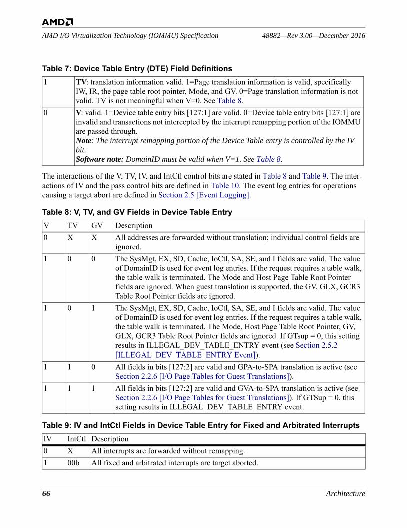
66 Architecture
48882—Rev 3.00—December 2016AMD I/O Virtualization Technology (IOMMU) Specification
The interactions of the V, TV, IV, and IntCtl control bits are stated in Table 8 and Table 9. The inter-actions of IV and the pass control bits are defined in Table 10. The event log entries for operations causing a target abort are defined in Section 2.5 [Event Logging].
1 TV: translation information valid. 1=Page translation information is valid, specifically IW, IR, the page table root pointer, Mode, and GV. 0=Page translation information is not valid. TV is not meaningful when V=0. See Table 8.
0 V: valid. 1=Device table entry bits [127:1] are valid. 0=Device table entry bits [127:1] are invalid and transactions not intercepted by the interrupt remapping portion of the IOMMU are passed through. Note: The interrupt remapping portion of the Device Table entry is controlled by the IV bit. Software note: DomainID must be valid when V=1. See Table 8.
Table 8: V, TV, and GV Fields in Device Table EntryV TV GV Description0 X X All addresses are forwarded without translation; individual control fields are
ignored.1 0 0 The SysMgt, EX, SD, Cache, IoCtl, SA, SE, and I fields are valid. The value
of DomainID is used for event log entries. If the request requires a table walk, the table walk is terminated. The Mode and Host Page Table Root Pointer fields are ignored. When guest translation is supported, the GV, GLX, GCR3 Table Root Pointer fields are ignored.
1 0 1 The SysMgt, EX, SD, Cache, IoCtl, SA, SE, and I fields are valid. The value of DomainID is used for event log entries. If the request requires a table walk, the table walk is terminated. The Mode, Host Page Table Root Pointer, GV, GLX, GCR3 Table Root Pointer fields are ignored. If GTsup = 0, this setting results in ILLEGAL_DEV_TABLE_ENTRY event (see Section 2.5.2 [ILLEGAL_DEV_TABLE_ENTRY Event]).
1 1 0 All fields in bits [127:2] are valid and GPA-to-SPA translation is active (see Section 2.2.6 [I/O Page Tables for Guest Translations]).
1 1 1 All fields in bits [127:2] are valid and GVA-to-SPA translation is active (see Section 2.2.6 [I/O Page Tables for Guest Translations]). If GTSup = 0, this setting results in ILLEGAL_DEV_TABLE_ENTRY event.
Table 9: IV and IntCtl Fields in Device Table Entry for Fixed and Arbitrated InterruptsIV IntCtl Description0 X All interrupts are forwarded without remapping.1 00b All fixed and arbitrated interrupts are target aborted.
Table 7: Device Table Entry (DTE) Field Definitions
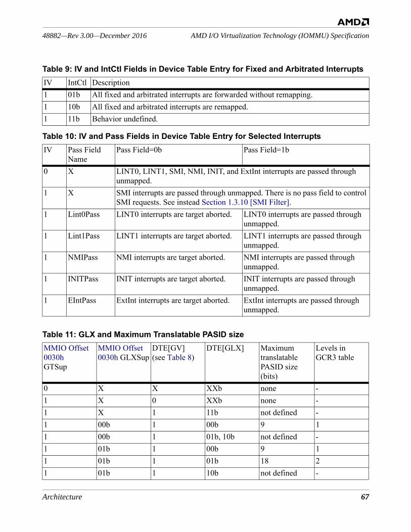
Architecture 67
AMD I/O Virtualization Technology (IOMMU) Specification48882—Rev 3.00—December 2016
1 01b All fixed and arbitrated interrupts are forwarded without remapping.1 10b All fixed and arbitrated interrupts are remapped.1 11b Behavior undefined.
Table 10: IV and Pass Fields in Device Table Entry for Selected InterruptsIV Pass Field
NamePass Field=0b Pass Field=1b
0 X LINT0, LINT1, SMI, NMI, INIT, and ExtInt interrupts are passed through unmapped.
1 X SMI interrupts are passed through unmapped. There is no pass field to control SMI requests. See instead Section 1.3.10 [SMI Filter].
1 Lint0Pass LINT0 interrupts are target aborted. LINT0 interrupts are passed through unmapped.
1 Lint1Pass LINT1 interrupts are target aborted. LINT1 interrupts are passed through unmapped.
1 NMIPass NMI interrupts are target aborted. NMI interrupts are passed through unmapped.
1 INITPass INIT interrupts are target aborted. INIT interrupts are passed through unmapped.
1 EIntPass ExtInt interrupts are target aborted. ExtInt interrupts are passed through unmapped.
Table 11: GLX and Maximum Translatable PASID sizeMMIO Offset 0030hGTSup
MMIO Offset 0030h GLXSup
DTE[GV](see Table 8)
DTE[GLX] Maximum translatable PASID size (bits)
Levels in GCR3 table
0 X X XXb none -1 X 0 XXb none -1 X 1 11b not defined -1 00b 1 00b 9 11 00b 1 01b, 10b not defined -1 01b 1 00b 9 11 01b 1 01b 18 21 01b 1 10b not defined -
Table 9: IV and IntCtl Fields in Device Table Entry for Fixed and Arbitrated InterruptsIV IntCtl Description
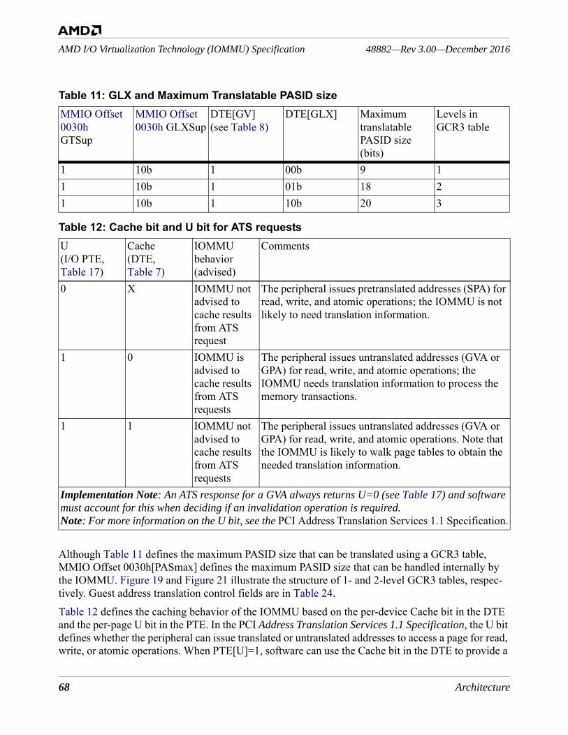
68 Architecture
48882—Rev 3.00—December 2016AMD I/O Virtualization Technology (IOMMU) Specification
Although Table 11 defines the maximum PASID size that can be translated using a GCR3 table, MMIO Offset 0030h[PASmax] defines the maximum PASID size that can be handled internally by the IOMMU. Figure 19 and Figure 21 illustrate the structure of 1- and 2-level GCR3 tables, respec-tively. Guest address translation control fields are in Table 24.Table 12 defines the caching behavior of the IOMMU based on the per-device Cache bit in the DTE and the per-page U bit in the PTE. In the PCI Address Translation Services 1.1 Specification, the U bit defines whether the peripheral can issue translated or untranslated addresses to access a page for read, write, or atomic operations. When PTE[U]=1, software can use the Cache bit in the DTE to provide a
1 10b 1 00b 9 11 10b 1 01b 18 21 10b 1 10b 20 3
Table 12: Cache bit and U bit for ATS requestsU(I/O PTE, Table 17)
Cache(DTE, Table 7)
IOMMU behavior (advised)
Comments
0 X IOMMU not advised to cache results from ATS request
The peripheral issues pretranslated addresses (SPA) for read, write, and atomic operations; the IOMMU is not likely to need translation information.
1 0 IOMMU is advised to cache results from ATS requests
The peripheral issues untranslated addresses (GVA or GPA) for read, write, and atomic operations; the IOMMU needs translation information to process the memory transactions.
1 1 IOMMU not advised to cache results from ATS requests
The peripheral issues untranslated addresses (GVA or GPA) for read, write, and atomic operations. Note that the IOMMU is likely to walk page tables to obtain the needed translation information.
Implementation Note: An ATS response for a GVA always returns U=0 (see Table 17) and software must account for this when deciding if an invalidation operation is required.Note: For more information on the U bit, see the PCI Address Translation Services 1.1 Specification.
Table 11: GLX and Maximum Translatable PASID sizeMMIO Offset 0030hGTSup
MMIO Offset 0030h GLXSup
DTE[GV](see Table 8)
DTE[GLX] Maximum translatable PASID size (bits)
Levels in GCR3 table

Architecture 69
AMD I/O Virtualization Technology (IOMMU) Specification48882—Rev 3.00—December 2016
caching hint to the IOMMU.2.2.2.2 Making Device Table Entry ChangesThis section contains information for software that changes the IOMMU tables. Software should issue invalidate commands after certain types of changes to tables and note that I/O device accesses are neither queued nor throttled by the IOMMU. Software may change the interrupt remapping infor-mation independently of the address translation information in a Device Table entry. These opera-tional sequences are general and system conditions may allow optimizations. Device table entry changes may affect guest OS I/O behavior, after invalidation commands have issued. Software may change the interrupt remapping information in a Device Table entry with a single 64-bit write. The change must be followed by an INVALIDATE_DEVTAB_ENTRY command when either the value of IV=1b or the value of V=1b before the change. If a 64-bit operation cannot be used, soft-ware may change the interrupt remapping information in the Device Table entry in the following manner, according to the value of IV before the change in the relevant Device Table entry. • If IV=0b before the change, changes can be made in any order as long as the last change is to set
to IV=1b; an INVALIDATE_DEVTAB_ENTRY command is required when the V=1b before the change.
• If IV=1b before the change, the following steps may be followed to change interrupt remapping information for fixed and arbitrated interrupts:• Set IntCtl=00b in the Device Table entry to block interrupts; any device-initiated interrupts for
the domain are target aborted and, when enabled, logged to the event log.• Update the interrupt table root pointer, IG, and IntTabLen.• Invalidate the interrupt table if the interrupt table root pointer or IntTabLen was changed (see
Section 2.4.5 [INVALIDATE_INTERRUPT_TABLE]).• Change IntCtl to cease blocking interrupts from the device (set IntCtl=01b or 10b).• Invalidate the Device Table entry (see Section 2.4.2 [INVALIDATE_DEVTAB_ENTRY]).
• If IV=1b before the change, the following steps change interrupt control information in the Device Table entry for NMI, LINT0, LINT1, INIT, and EXTINT interrupts:• Update Lint1Pass, Lint0Pass, IntCtl, NMIPass, EIntPass, and InitPass. The setting of IntCtl
can be changed at the same time.• Invalidate the Device Table entry for the device (see Section 2.4.2
[INVALIDATE_DEVTAB_ENTRY]).
Software may change the address translation information in a Device Table entry with a single 128-bit write operation followed by an INVALIDATE_DEVTAB_ENTRY command when either IV=1b or V=1b before the change. If a 128-bit operation cannot be used, software may change the address translation information in the following ways, according to the values of V and TV before the change.• If V=0b before the change, address translation changes can be made in any order as long as the
last change is to set V=1b. An INVALIDATE_DEVTAB_ENTRY command is required if IV=1b before the change.
• If V=1b before the change, software can use the following steps to set the IOMMU to pass addresses untranslated with access controlled by IR and IW, depending on the value of TV.
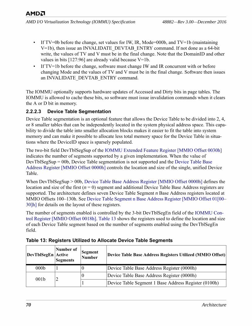
70 Architecture
48882—Rev 3.00—December 2016AMD I/O Virtualization Technology (IOMMU) Specification
• If TV=0b before the change, set values for IW, IR, Mode=000b, and TV=1b (maintaining V=1b), then issue an INVALIDATE_DEVTAB_ENTRY command. If not done as a 64-bit write, the values of TV and V must be in the final change. Note that the DomainID and other values in bits [127:96] are already valid because V=1b.
• If TV=1b before the change, software must change IW and IR concurrent with or before changing Mode and the values of TV and V must be in the final change. Software then issues an INVALIDATE_DEVTAB_ENTRY command.
The IOMMU optionally supports hardware updates of Accessed and Dirty bits in page tables. The IOMMU is allowed to cache these bits, so software must issue invalidation commands when it clears the A or D bit in memory.2.2.2.3 Device Table SegmentationDevice Table segmentation is an optional feature that allows the Device Table to be divided into 2, 4, or 8 smaller tables that can be independently located in the system physical address space. This capa-bility to divide the table into smaller allocation blocks makes it easier to fit the table into system memory and can make it possible to allocate less total memory space for the Device Table in situa-tions where the DeviceID space is sparsely populated.The two-bit field DevTblSegSup of the IOMMU Extended Feature Register [MMIO Offset 0030h] indicates the number of segments supported by a given implementation. When the value of DevTblSegSup = 00b, Device Table segmentation is not supported and the Device Table Base Address Register [MMIO Offset 0000h] controls the location and size of the single, unified Device Table.When DevTblSegSup > 00b, Device Table Base Address Register [MMIO Offset 0000h] defines the location and size of the first (n = 0) segment and additional Device Table Base Address registers are supported. The architecture defines seven Device Table Segment n Base Address registers located at MMIO Offsets 100–130h. See Device Table Segment n Base Address Register [MMIO Offset 01[00–30]h] for details on the layout of these registers. The number of segments enabled is controlled by the 3-bit DevTblSegEn field of the IOMMU Con-trol Register [MMIO Offset 0018h]. Table 13 shows the registers used to define the location and size of each Device Table segment based on the number of segments enabled using the DevTblSegEn field.
Table 13: Registers Utilized to Allocate Device Table Segments
DevTblSegEnNumber of Active Segments
Segment Number Device Table Base Address Registers Utilized (MMIO Offset)
000b 1 0 Device Table Base Address Register (0000h)
001b 20 Device Table Base Address Register (0000h)1 Device Table Segment 1 Base Address Register (0100h)
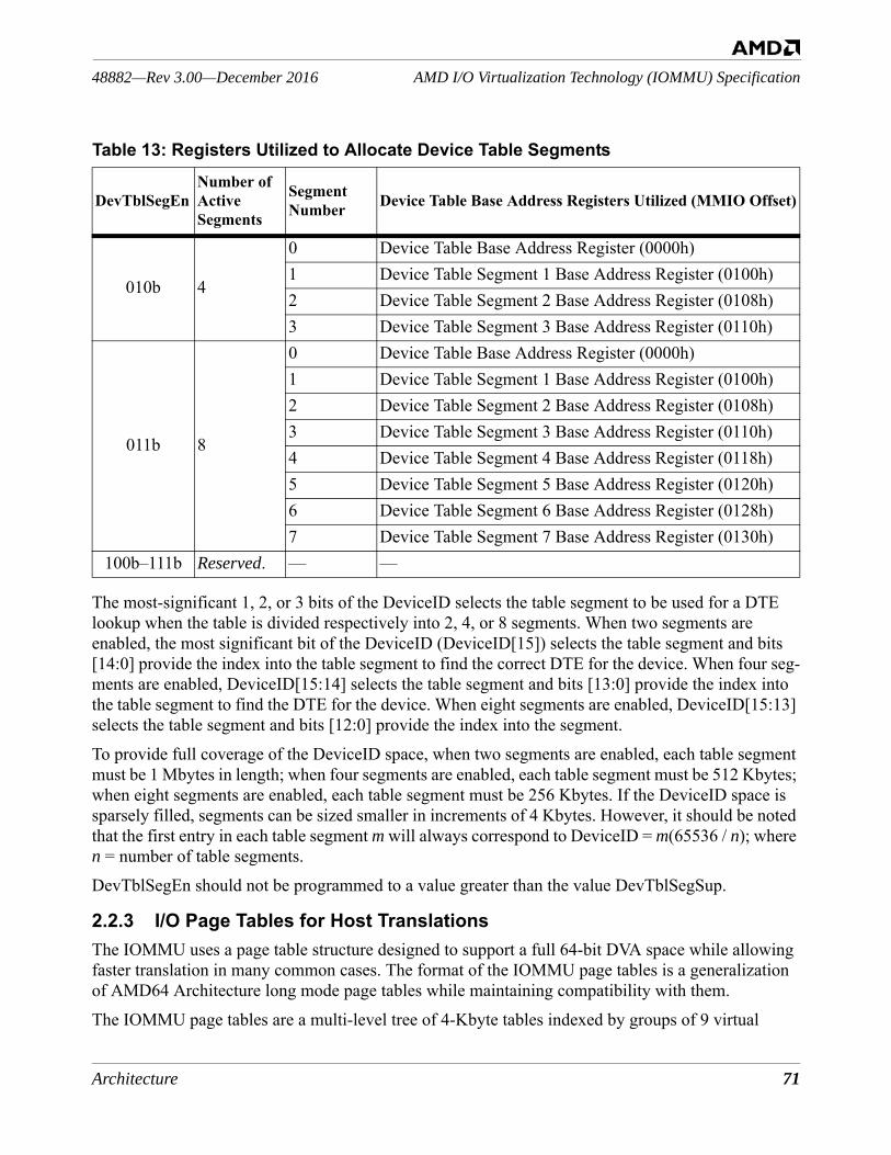
Architecture 71
AMD I/O Virtualization Technology (IOMMU) Specification48882—Rev 3.00—December 2016
The most-significant 1, 2, or 3 bits of the DeviceID selects the table segment to be used for a DTE lookup when the table is divided respectively into 2, 4, or 8 segments. When two segments are enabled, the most significant bit of the DeviceID (DeviceID[15]) selects the table segment and bits [14:0] provide the index into the table segment to find the correct DTE for the device. When four seg-ments are enabled, DeviceID[15:14] selects the table segment and bits [13:0] provide the index into the table segment to find the DTE for the device. When eight segments are enabled, DeviceID[15:13] selects the table segment and bits [12:0] provide the index into the segment.To provide full coverage of the DeviceID space, when two segments are enabled, each table segment must be 1 Mbytes in length; when four segments are enabled, each table segment must be 512 Kbytes; when eight segments are enabled, each table segment must be 256 Kbytes. If the DeviceID space is sparsely filled, segments can be sized smaller in increments of 4 Kbytes. However, it should be noted that the first entry in each table segment m will always correspond to DeviceID = m(65536 / n); where n = number of table segments.DevTblSegEn should not be programmed to a value greater than the value DevTblSegSup.
2.2.3 I/O Page Tables for Host TranslationsThe IOMMU uses a page table structure designed to support a full 64-bit DVA space while allowing faster translation in many common cases. The format of the IOMMU page tables is a generalization of AMD64 Architecture long mode page tables while maintaining compatibility with them. The IOMMU page tables are a multi-level tree of 4-Kbyte tables indexed by groups of 9 virtual
010b 4
0 Device Table Base Address Register (0000h)1 Device Table Segment 1 Base Address Register (0100h)2 Device Table Segment 2 Base Address Register (0108h)3 Device Table Segment 3 Base Address Register (0110h)
011b 8
0 Device Table Base Address Register (0000h)1 Device Table Segment 1 Base Address Register (0100h)2 Device Table Segment 2 Base Address Register (0108h)3 Device Table Segment 3 Base Address Register (0110h)4 Device Table Segment 4 Base Address Register (0118h)5 Device Table Segment 5 Base Address Register (0120h)6 Device Table Segment 6 Base Address Register (0128h)7 Device Table Segment 7 Base Address Register (0130h)
100b–111b Reserved. — —
Table 13: Registers Utilized to Allocate Device Table Segments
DevTblSegEnNumber of Active Segments
Segment Number Device Table Base Address Registers Utilized (MMIO Offset)
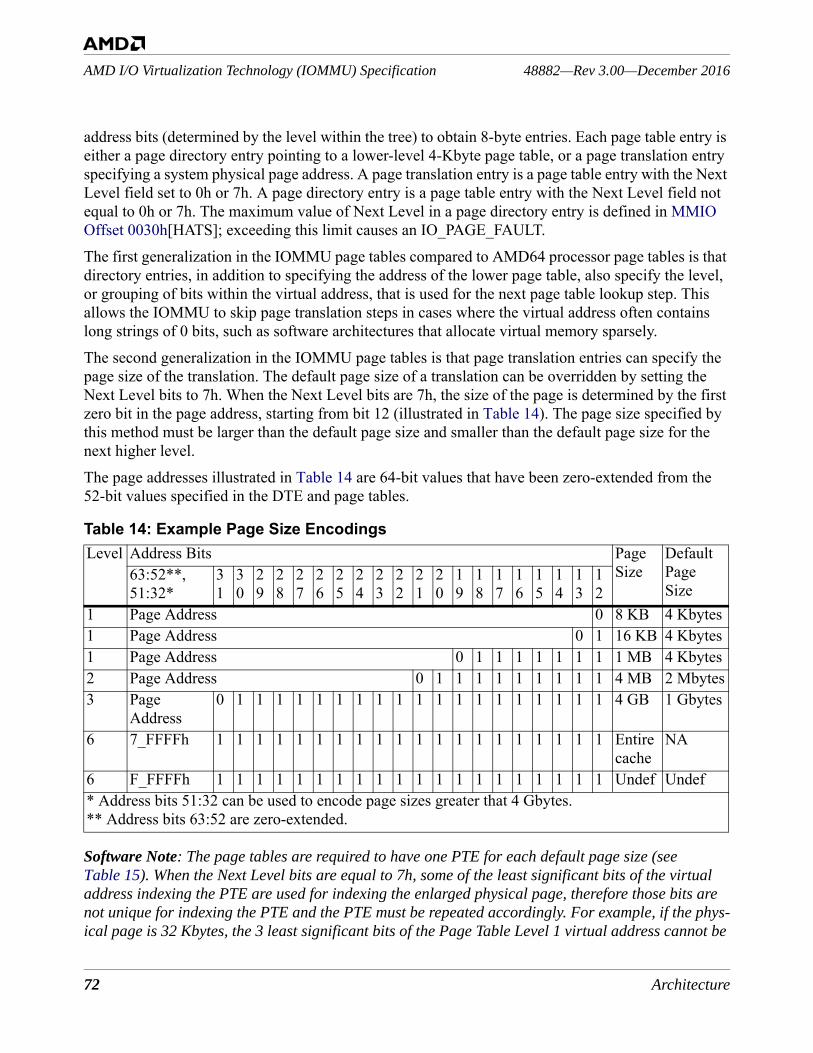
72 Architecture
48882—Rev 3.00—December 2016AMD I/O Virtualization Technology (IOMMU) Specification
address bits (determined by the level within the tree) to obtain 8-byte entries. Each page table entry is either a page directory entry pointing to a lower-level 4-Kbyte page table, or a page translation entry specifying a system physical page address. A page translation entry is a page table entry with the Next Level field set to 0h or 7h. A page directory entry is a page table entry with the Next Level field not equal to 0h or 7h. The maximum value of Next Level in a page directory entry is defined in MMIO Offset 0030h[HATS]; exceeding this limit causes an IO_PAGE_FAULT. The first generalization in the IOMMU page tables compared to AMD64 processor page tables is that directory entries, in addition to specifying the address of the lower page table, also specify the level, or grouping of bits within the virtual address, that is used for the next page table lookup step. This allows the IOMMU to skip page translation steps in cases where the virtual address often contains long strings of 0 bits, such as software architectures that allocate virtual memory sparsely.The second generalization in the IOMMU page tables is that page translation entries can specify the page size of the translation. The default page size of a translation can be overridden by setting the Next Level bits to 7h. When the Next Level bits are 7h, the size of the page is determined by the first zero bit in the page address, starting from bit 12 (illustrated in Table 14). The page size specified by this method must be larger than the default page size and smaller than the default page size for the next higher level.The page addresses illustrated in Table 14 are 64-bit values that have been zero-extended from the 52-bit values specified in the DTE and page tables.
Software Note: The page tables are required to have one PTE for each default page size (see Table 15). When the Next Level bits are equal to 7h, some of the least significant bits of the virtual address indexing the PTE are used for indexing the enlarged physical page, therefore those bits are not unique for indexing the PTE and the PTE must be repeated accordingly. For example, if the phys-ical page is 32 Kbytes, the 3 least significant bits of the Page Table Level 1 virtual address cannot be
Table 14: Example Page Size EncodingsLevel Address Bits Page
SizeDefault Page Size
63:52**, 51:32*
31
30
29
28
27
26
25
24
23
22
21
20
19
18
17
16
15
14
13
12
1 Page Address 0 8 KB 4 Kbytes1 Page Address 0 1 16 KB 4 Kbytes1 Page Address 0 1 1 1 1 1 1 1 1 MB 4 Kbytes2 Page Address 0 1 1 1 1 1 1 1 1 1 4 MB 2 Mbytes3 Page
Address0 1 1 1 1 1 1 1 1 1 1 1 1 1 1 1 1 1 1 1 4 GB 1 Gbytes
6 7_FFFFh 1 1 1 1 1 1 1 1 1 1 1 1 1 1 1 1 1 1 1 1 Entire cache
NA
6 F_FFFFh 1 1 1 1 1 1 1 1 1 1 1 1 1 1 1 1 1 1 1 1 Undef Undef* Address bits 51:32 can be used to encode page sizes greater that 4 Gbytes.** Address bits 63:52 are zero-extended.
Architecture 73
AMD I/O Virtualization Technology (IOMMU) Specification48882—Rev 3.00—December 2016
used only for indexing within the page table and therefore the PTE must be repeated 8 times for each of the 64 unique PTEs given 4-Kbyte page tables. Another example for 4-Mbyte pages is illustrated in Figure 12. The PTE in the Level-2 page table is replicated twice and bit 21 of the virtual address is used twice for indexing, first to index the Level-2 table of PTEs and again to index into the 4-Mbyte page for the data. The replicated Level-2 PTEs have identical contents and follow the example in Table 14 for a page size of 4 Mbytes. For larger page sizes, the PTEs must be replicated an appropri-ate number of times so that more bits of the virtual address can be used for indexing.
Implementation Note: While IOMMU implementations are not strictly required to include translation caches, it is strongly recommended that they include at least a cache for translations of 4-Kbyte page table entries. IOMMU implementations can cache translations of larger pages by splitting them into multiple 4-Kbyte cache entries.
The page table pointer for each domain specifies the system physical address and level of the root page table for that domain. Translation of a DVA begins by comparing it to the root page table’s level. If the address contains any nonzero bits in bit positions higher than the range selected by the root page table’s level, translation terminates with an IO_PAGE_FAULT. Otherwise, the appropriate group of virtual address bits is used to fetch a page table entry from the root page table. If this entry is marked not present, translation terminates with an IO_PAGE_FAULT. Otherwise the entry may be a page directory entry pointing to a lower-level page table (in which case the translation process repeats starting at the new page table using the remaining virtual address bits), or it may be a page translation entry containing the final system physical address (in which case the translation process terminates and the remaining DVA bits are concatenated with the translation entry’s physical address to obtain a translated address). If a translation skips levels and any of the skipped virtual address bits are non-zero, translation terminates with an IO_PAGE_FAULT.Effective write permission is calculated using the IW bits in the DTE (see Table 7), the I/O PDEs, and the I/O PTE. Device accesses to translated addresses are first checked against these cumulative per-missions before being allowed to proceed. IW and IR bits from skipped levels are treated as if they were 1s. For a discussion of guest and host permissions, see Section 2.2.7 [Guest and Nested Address Translation].Table 15 specifies the virtual address bit groups used for indexing at each level of the page tables, as well as the default page sizes associated with page translation entries fetched from page tables at each level. Figure 8 and Figure 9 illustrate the formats of page table entries. If a page table entry contains nonzero bits in any of the fields marked reserved, if the Next Level field is greater than or equal to the current page table entry table’s level, or if a page translation entry’s physical address is not aligned to a multiple of the appropriate page size for the current page table entry page table’s level, translation terminates with an IO_PAGE_FAULT.The layout of IOMMU page table entries has been chosen so that the IOMMU can use AMD64 long mode processor page tables, provided the Next Level fields (which occupy bit positions ignored by AMD64 processors) are properly initialized according to their level within the processor page tables. (AMD64 processors lack the IOMMU’s level skipping facility.) All other page table entry fields used by the IOMMU are either ignored by AMD64 processors, or have the same meaning to both the pro-cessor and the IOMMU. For more details on sharing page tables see Section 2.2.4 [Sharing AMD64 Processor and IOMMU Page Tables—GPA-to-SPA].

74 Architecture
48882—Rev 3.00—December 2016AMD I/O Virtualization Technology (IOMMU) Specification
The U bit in the page tables is an attribute bit passed to peripherals in ATS responses. See Table 12 for the behavior of the IOMMU for settings of the DTE[Cache] and PTE[U] fields.IOMMU implementations must zero-fill all high-order physical address (SPA).The IOMMU fields are architected to produce a physical address of up to 52 bits, thus physical address bits [63:53] are always zero.
Table 15: Page Table Level ParametersPage Table Level
Virtual address bits indexing table
Default Page size (bytes) for translation entries
6 63:57 NA5 56:48 248
4 47:39 239
3 38:30 230
2 29:21 221
1 20:12 4096
63 32
Ignored
31 1 0
Ignored
PR=0
Figure 8: I/O Page Table Entry Not Present (any level)
Table 16: I/O Page Table Entry Not Present Fields, PR=0Bits Description63:1 Ignored when PR=0. 0 PR: Present. 0=the remainder of the I/O page table entry is ignored and the corresponding
memory page is considered not-present (see Section 2.5.3 [IO_PAGE_FAULT Event]). When PR=1, see Table 17 and Table 18.
63 62 61 60 59 58 52 51 32
Ign IW IR FC U Reserved Page Address[51:32]
31 12 11 9 8 7 6 5 4 1 0
Page Address[31:12]Next Level [2:0]=000b
or 111bIgnored D A Ignored
PR=1
Figure 9: I/O Page Translation Entry (PTE), PR=1
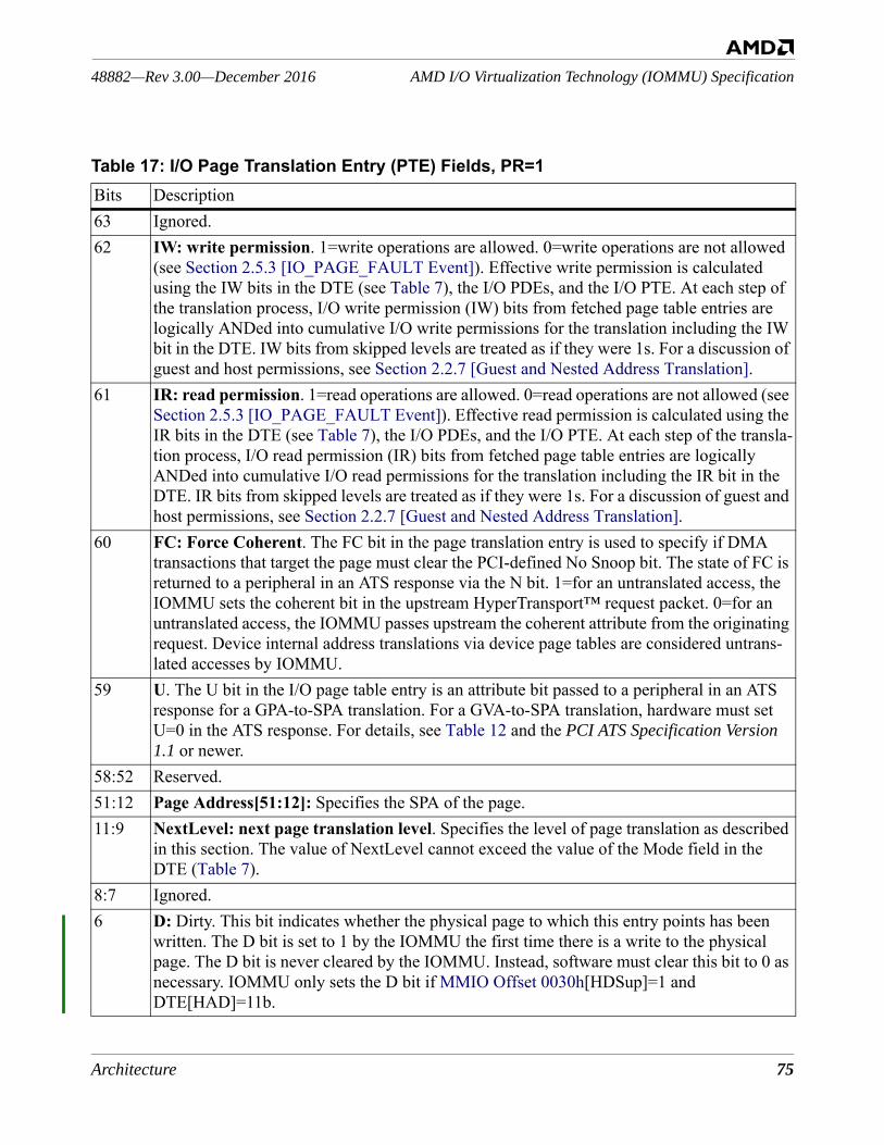
Architecture 75
AMD I/O Virtualization Technology (IOMMU) Specification48882—Rev 3.00—December 2016
Table 17: I/O Page Translation Entry (PTE) Fields, PR=1 Bits Description63 Ignored.62 IW: write permission. 1=write operations are allowed. 0=write operations are not allowed
(see Section 2.5.3 [IO_PAGE_FAULT Event]). Effective write permission is calculated using the IW bits in the DTE (see Table 7), the I/O PDEs, and the I/O PTE. At each step of the translation process, I/O write permission (IW) bits from fetched page table entries are logically ANDed into cumulative I/O write permissions for the translation including the IW bit in the DTE. IW bits from skipped levels are treated as if they were 1s. For a discussion of guest and host permissions, see Section 2.2.7 [Guest and Nested Address Translation].
61 IR: read permission. 1=read operations are allowed. 0=read operations are not allowed (see Section 2.5.3 [IO_PAGE_FAULT Event]). Effective read permission is calculated using the IR bits in the DTE (see Table 7), the I/O PDEs, and the I/O PTE. At each step of the transla-tion process, I/O read permission (IR) bits from fetched page table entries are logically ANDed into cumulative I/O read permissions for the translation including the IR bit in the DTE. IR bits from skipped levels are treated as if they were 1s. For a discussion of guest and host permissions, see Section 2.2.7 [Guest and Nested Address Translation].
60 FC: Force Coherent. The FC bit in the page translation entry is used to specify if DMA transactions that target the page must clear the PCI-defined No Snoop bit. The state of FC is returned to a peripheral in an ATS response via the N bit. 1=for an untranslated access, the IOMMU sets the coherent bit in the upstream HyperTransport™ request packet. 0=for an untranslated access, the IOMMU passes upstream the coherent attribute from the originating request. Device internal address translations via device page tables are considered untrans-lated accesses by IOMMU.
59 U. The U bit in the I/O page table entry is an attribute bit passed to a peripheral in an ATS response for a GPA-to-SPA translation. For a GVA-to-SPA translation, hardware must set U=0 in the ATS response. For details, see Table 12 and the PCI ATS Specification Version 1.1 or newer.
58:52 Reserved.51:12 Page Address[51:12]: Specifies the SPA of the page.11:9 NextLevel: next page translation level. Specifies the level of page translation as described
in this section. The value of NextLevel cannot exceed the value of the Mode field in the DTE (Table 7).
8:7 Ignored.6 D: Dirty. This bit indicates whether the physical page to which this entry points has been
written. The D bit is set to 1 by the IOMMU the first time there is a write to the physical page. The D bit is never cleared by the IOMMU. Instead, software must clear this bit to 0 as necessary. IOMMU only sets the D bit if MMIO Offset 0030h[HDSup]=1 and DTE[HAD]=11b.
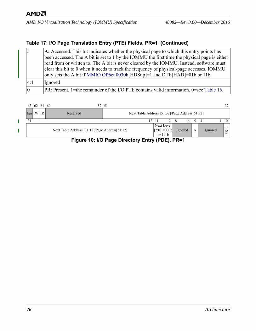
76 Architecture
48882—Rev 3.00—December 2016AMD I/O Virtualization Technology (IOMMU) Specification
5 A: Accessed. This bit indicates whether the physical page to which this entry points has been accessed. The A bit is set to 1 by the IOMMU the first time the physical page is either read from or written to. The A bit is never cleared by the IOMMU. Instead, software must clear this bit to 0 when it needs to track the frequency of physical-page accesses. IOMMU only sets the A bit if MMIO Offset 0030h[HDSup]=1 and DTE[HAD]=01b or 11b.
4:1 Ignored0 PR: Present. 1=the remainder of the I/O PTE contains valid information. 0=see Table 16.
63 62 61 60 52 51 32
Ign IW IR Reserved Next Table Address [51:32]/Page Address[51:32]
31 12 11 9 8 6 5 4 1 0
Next Table Address [31:12]/Page Address[31:12]Next Level [2:0]!=000b
or 111bIgnored A Ignored
PR=1
Figure 10: I/O Page Directory Entry (PDE), PR=1
Table 17: I/O Page Translation Entry (PTE) Fields, PR=1 (Continued)
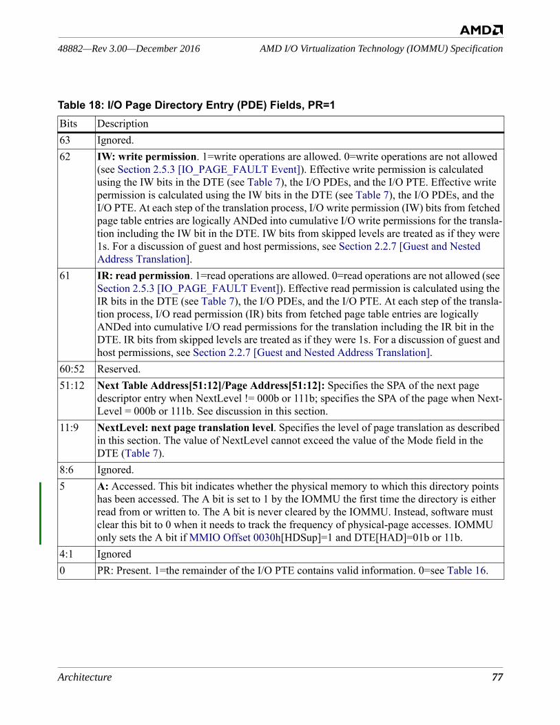
Architecture 77
AMD I/O Virtualization Technology (IOMMU) Specification48882—Rev 3.00—December 2016
Table 18: I/O Page Directory Entry (PDE) Fields, PR=1Bits Description63 Ignored.62 IW: write permission. 1=write operations are allowed. 0=write operations are not allowed
(see Section 2.5.3 [IO_PAGE_FAULT Event]). Effective write permission is calculated using the IW bits in the DTE (see Table 7), the I/O PDEs, and the I/O PTE. Effective write permission is calculated using the IW bits in the DTE (see Table 7), the I/O PDEs, and the I/O PTE. At each step of the translation process, I/O write permission (IW) bits from fetched page table entries are logically ANDed into cumulative I/O write permissions for the transla-tion including the IW bit in the DTE. IW bits from skipped levels are treated as if they were 1s. For a discussion of guest and host permissions, see Section 2.2.7 [Guest and Nested Address Translation].
61 IR: read permission. 1=read operations are allowed. 0=read operations are not allowed (see Section 2.5.3 [IO_PAGE_FAULT Event]). Effective read permission is calculated using the IR bits in the DTE (see Table 7), the I/O PDEs, and the I/O PTE. At each step of the transla-tion process, I/O read permission (IR) bits from fetched page table entries are logically ANDed into cumulative I/O read permissions for the translation including the IR bit in the DTE. IR bits from skipped levels are treated as if they were 1s. For a discussion of guest and host permissions, see Section 2.2.7 [Guest and Nested Address Translation].
60:52 Reserved.51:12 Next Table Address[51:12]/Page Address[51:12]: Specifies the SPA of the next page
descriptor entry when NextLevel != 000b or 111b; specifies the SPA of the page when Next-Level = 000b or 111b. See discussion in this section.
11:9 NextLevel: next page translation level. Specifies the level of page translation as described in this section. The value of NextLevel cannot exceed the value of the Mode field in the DTE (Table 7).
8:6 Ignored.5 A: Accessed. This bit indicates whether the physical memory to which this directory points
has been accessed. The A bit is set to 1 by the IOMMU the first time the directory is either read from or written to. The A bit is never cleared by the IOMMU. Instead, software must clear this bit to 0 when it needs to track the frequency of physical-page accesses. IOMMU only sets the A bit if MMIO Offset 0030h[HDSup]=1 and DTE[HAD]=01b or 11b.
4:1 Ignored0 PR: Present. 1=the remainder of the I/O PTE contains valid information. 0=see Table 16.
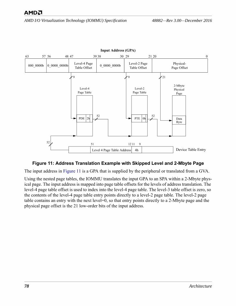
78 Architecture
48882—Rev 3.00—December 2016AMD I/O Virtualization Technology (IOMMU) Specification
Figure 11: Address Translation Example with Skipped Level and 2-Mbyte PageThe input address in Figure 11 is a GPA that is supplied by the peripheral or translated from a GVA. Using the nested page tables, the IOMMU translates the input GPA to an SPA within a 2-Mbyte phys-ical page. The input address is mapped into page table offsets for the levels of address translation. The level-4 page table offset is used to index into the level-4 page table. The level-3 table offset is zero, so the contents of the level-4 page table entry points directly to a level-2 page table. The level-2 page table contains an entry with the next level=0, so that entry points directly to a 2-Mbyte page and the physical page offset is the 21 low-order bits of the input address.
Input Address (GPA)
0_0000_0000b Level-2 PageTable Offset
0202129303839474863
DataByte
219
52
1251
Device Table Entry
Level-4Page Table
2-Mbyte Physical
Page
Physical-Page Offset
Level 4 Page Table Address
911
57 56
2h
Level-4 PageTable Offset
9
52
Level-2Page Table
0_0000_0000b000_0000b
PDE 0hPTE
52
4h
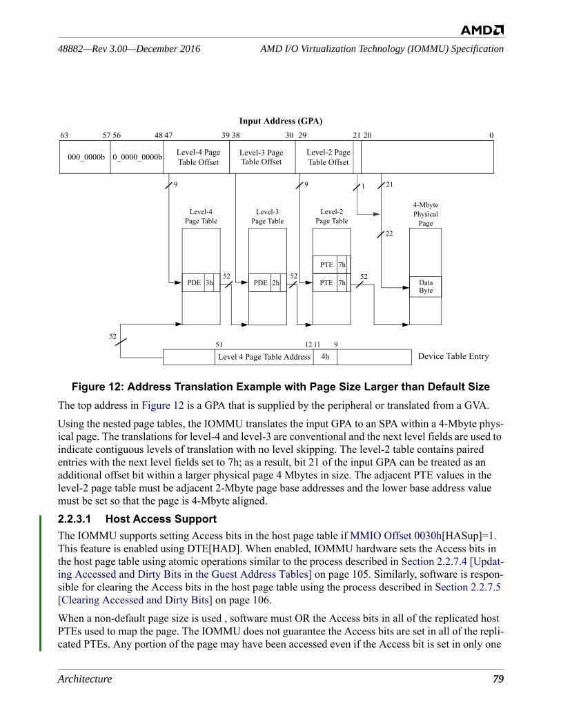
Architecture 79
AMD I/O Virtualization Technology (IOMMU) Specification48882—Rev 3.00—December 2016
Figure 12: Address Translation Example with Page Size Larger than Default SizeThe top address in Figure 12 is a GPA that is supplied by the peripheral or translated from a GVA.Using the nested page tables, the IOMMU translates the input GPA to an SPA within a 4-Mbyte phys-ical page. The translations for level-4 and level-3 are conventional and the next level fields are used to indicate contiguous levels of translation with no level skipping. The level-2 table contains paired entries with the next level fields set to 7h; as a result, bit 21 of the input GPA can be treated as an additional offset bit within a larger physical page 4 Mbytes in size. The adjacent PTE values in the level-2 page table must be adjacent 2-Mbyte page base addresses and the lower base address value must be set so that the page is 4-Mbyte aligned.2.2.3.1 Host Access SupportThe IOMMU supports setting Access bits in the host page table if MMIO Offset 0030h[HASup]=1. This feature is enabled using DTE[HAD]. When enabled, IOMMU hardware sets the Access bits in the host page table using atomic operations similar to the process described in Section 2.2.7.4 [Updat-ing Accessed and Dirty Bits in the Guest Address Tables] on page 105. Similarly, software is respon-sible for clearing the Access bits in the host page table using the process described in Section 2.2.7.5 [Clearing Accessed and Dirty Bits] on page 106.When a non-default page size is used , software must OR the Access bits in all of the replicated host PTEs used to map the page. The IOMMU does not guarantee the Access bits are set in all of the repli-cated PTEs. Any portion of the page may have been accessed even if the Access bit is set in only one
Input Address (GPA)
Level-3 Page Level-2 PageTable Offset
0202129303839474863
219
52
1251Device Table Entry
Level-4Page Table
4-Mbyte Physical
Page
Physical-Page Offset
Level 4 Page Table Address 4h911
57 56
3h
Level-4 PageTable Offset
9
52
Level-2Page Table
0_0000_0000b000_0000b
PDE 7hPTE
Level-3Page Table
2hPDE52
Table Offset
7hPTE
22
1
52
DataByte
80 Architecture
48882—Rev 3.00—December 2016AMD I/O Virtualization Technology (IOMMU) Specification
of the replicated PTEs.Hypervisor software may use the host access bits to help decide whether a piece of guest memory should be paged out. Such software must also ensure that the guest memory is safe to page out. The mechanisms for doing so are outside the scope of the IOMMU specification.2.2.3.2 Host Dirty SupportThe IOMMU supports setting the Dirty bit in the lowest level of the host page table if MMIO Offset 0030h[HDSup]=1. This feature is enabled using DTE[HAD]. When enabled, IOMMU hardware sets the Dirty bit in the host page table using an atomic operation similar to the process described in Sec-tion 2.2.7.4 [Updating Accessed and Dirty Bits in the Guest Address Tables] on page 105. Similarly, software is responsible for clearing the Dirty bit in the host page table using the process described in Section 2.2.7.5 [Clearing Accessed and Dirty Bits] on page 106.When a non-default page size is used , software must OR the Dirty bits in all of the replicated host PTEs used to map the page. The IOMMU does not guarantee the Dirty bits are set in all of the repli-cated PTEs. Any portion of the page may have been written even if the Dirty bit is set in only one of the replicated PTEs. Hypervisor software may use the host dirty bit to optimize the page out of guest memory by avoiding redundant writes to the pagefile.
2.2.4 Sharing AMD64 Processor and IOMMU Page Tables—GPA-to-SPAThis section outlines the topics to be considered so that the host or GPA-to-SPA page tables may be shared with an IOMMU in an AMD64 system. A more complete discussion depends on many imple-mentation factors.AMD64 processors and the IOMMU treat upper virtual address bits [63:48] differently. The proces-sor requires canonical addresses (in which address bits [63:48] are equal to bit 47). By contrast, the IOMMU is designed to support the full PCI 64-bit address space. If 6-level page tables are used, the IOMMU can map any 64-bit address. If fewer than 6 levels are used, the IOMMU requires upper vir-tual address bits (beyond the range mapped by the page tables) to be 0. This ensures that software can always add levels to page tables without changing the address space as seen by devices.In AMD64 long mode level 4 page tables, the bottom 256 entries of the root page table correspond to positive virtual addresses with bits [63:47] all 0s and the top 256 entries correspond to negative vir-tual addresses with bits [63:47] all 1s.For the IOMMU to directly share processor page tables, at a minimum the Next Level fields in all page table entries must be initialized with correct values for the IOMMU.Once the Next Level fields are initialized, the IOMMU may directly share exactly the same page tables. In 3-level 32-bit PAE mode this is all that's needed. However, in 4-level long mode software should be aware that processor virtual addresses in the range FFFF_8000_0000_0000h to FFFF_FFFF_FFFF_FFFFh correspond to I/O virtual addresses in the range 0000_8000_0000_0000h to 0000_FFFF_FFFF_FFFFh.If software requires 64-bit processor virtual addresses to be identical to I/O virtual addresses, includ-
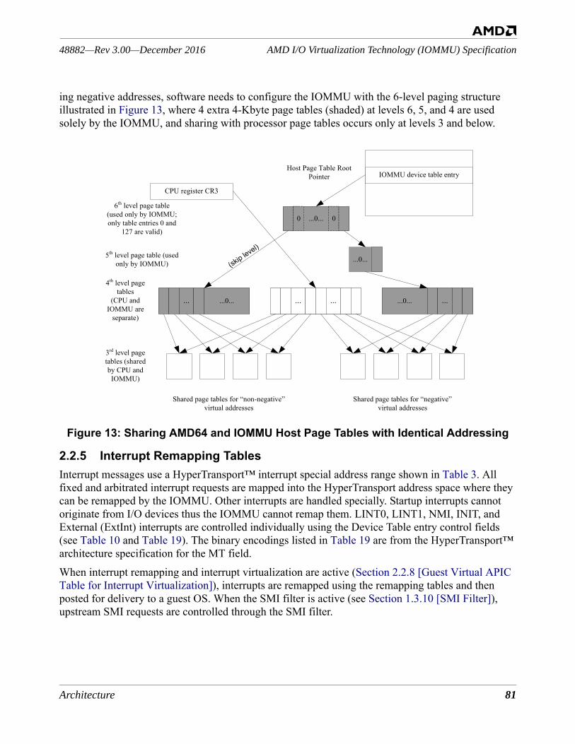
Architecture 81
AMD I/O Virtualization Technology (IOMMU) Specification48882—Rev 3.00—December 2016
ing negative addresses, software needs to configure the IOMMU with the 6-level paging structure illustrated in Figure 13, where 4 extra 4-Kbyte page tables (shaded) at levels 6, 5, and 4 are used solely by the IOMMU, and sharing with processor page tables occurs only at levels 3 and below.
Figure 13: Sharing AMD64 and IOMMU Host Page Tables with Identical Addressing
2.2.5 Interrupt Remapping TablesInterrupt messages use a HyperTransport™ interrupt special address range shown in Table 3. All fixed and arbitrated interrupt requests are mapped into the HyperTransport address space where they can be remapped by the IOMMU. Other interrupts are handled specially. Startup interrupts cannot originate from I/O devices thus the IOMMU cannot remap them. LINT0, LINT1, NMI, INIT, and External (ExtInt) interrupts are controlled individually using the Device Table entry control fields (see Table 10 and Table 19). The binary encodings listed in Table 19 are from the HyperTransport™ architecture specification for the MT field.When interrupt remapping and interrupt virtualization are active (Section 2.2.8 [Guest Virtual APIC Table for Interrupt Virtualization]), interrupts are remapped using the remapping tables and then posted for delivery to a guest OS. When the SMI filter is active (see Section 1.3.10 [SMI Filter]), upstream SMI requests are controlled through the SMI filter.
...0... 00
...0...
... ...... ...0... ...0... ...
(skip level)
IOMMU device table entry
CPU register CR3
4th level page tables
(CPU and IOMMU are
separate)
3rd level page tables (shared by CPU and
IOMMU)
5th level page table (used only by IOMMU)
6th level page table(used only by IOMMU; only table entries 0 and
127 are valid)
Shared page tables for “non-negative” virtual addresses
Shared page tables for “negative” virtual addresses
Host Page Table Root Pointer
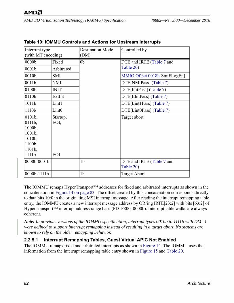
82 Architecture
48882—Rev 3.00—December 2016AMD I/O Virtualization Technology (IOMMU) Specification
The IOMMU remaps HyperTransport™ addresses for fixed and arbitrated interrupts as shown in the concatenation in Figure 14 on page 83. The offset created by this concatenation corresponds directly to data bits 10:0 in the originating MSI interrupt message. After reading the interrupt remapping table entry, the IOMMU creates a new interrupt message address by OR’ing IRTE[23:2] with bits [63:2] of HyperTransport™ interrupt address range base (FD_F800_0000h). Interrupt table walks are always coherent.Note: In previous versions of the IOMMU specification, interrupt types 0010b to 1111b with DM=1 were defined to support interrupt remapping instead of resulting in a target abort. No systems are known to rely on the older remapping behavior.
2.2.5.1 Interrupt Remapping Tables, Guest Virtual APIC Not EnabledThe IOMMU remaps fixed and arbitrated interrupts as shown in Figure 14. The IOMMU uses the information from the interrupt remapping table entry shown in Figure 15 and Table 20.
Table 19: IOMMU Controls and Actions for Upstream InterruptsInterrupt type (with MT encoding)
Destination Mode (DM)
Controlled by
0000b Fixed 0b DTE and IRTE (Table 7 and Table 20)0001b Arbitrated
0010b SMI MMIO Offset 0018h[SmiFLogEn]0011b NMI DTE[NMIPass] (Table 7)0100b INIT DTE[InitPass] (Table 7)0110b ExtInt DTE[EIntPass] (Table 7)1011b Lint1 DTE[Lint1Pass] (Table 7)1110b Lint0 DTE[Lint0Pass] (Table 7)0101b,0111b,1000b,1001b, 1010b,1100b,1101b,1111b
Startup,EOI,
EOI
Target abort
0000b-0001b 1b DTE and IRTE (Table 7 and Table 20)
0000b-1111b 1b Target Abort
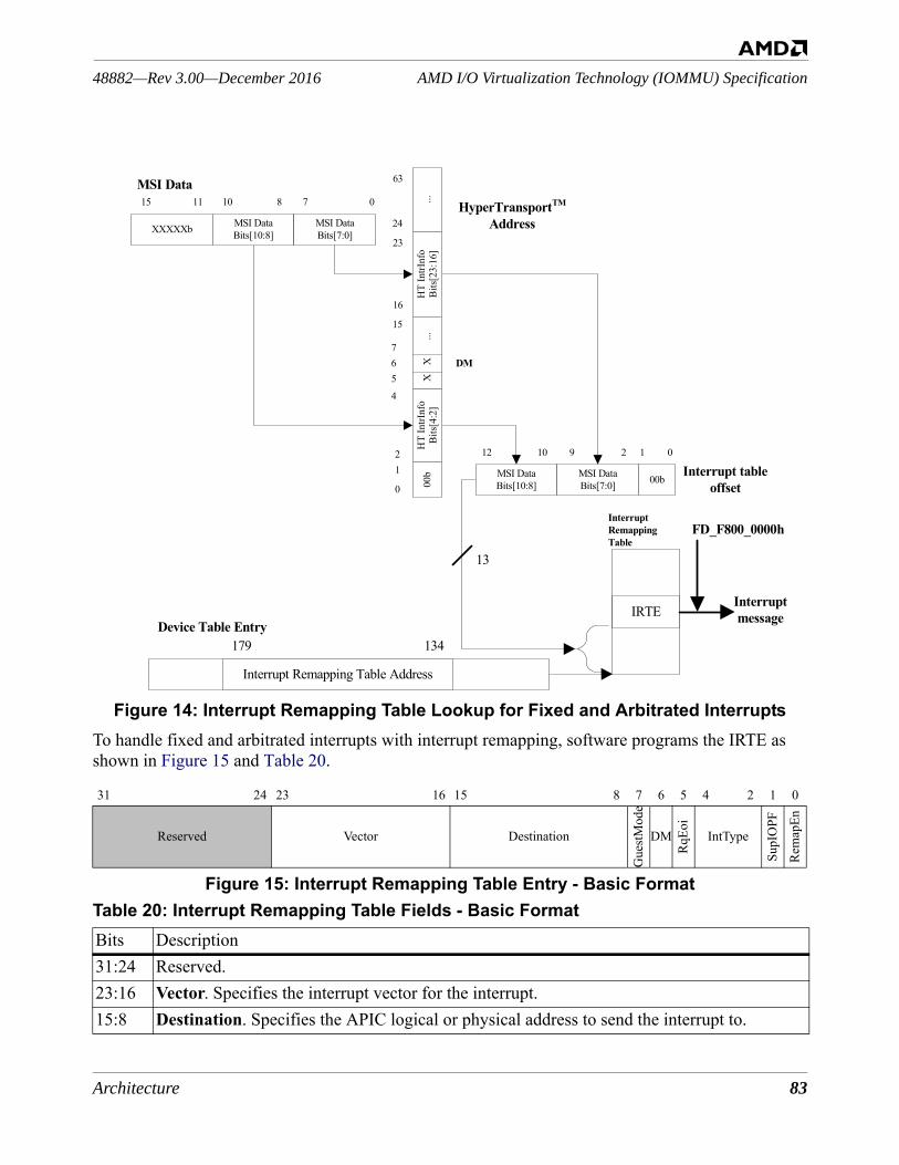
Architecture 83
AMD I/O Virtualization Technology (IOMMU) Specification48882—Rev 3.00—December 2016
Figure 14: Interrupt Remapping Table Lookup for Fixed and Arbitrated InterruptsTo handle fixed and arbitrated interrupts with interrupt remapping, software programs the IRTE as shown in Figure 15 and Table 20.
Figure 15: Interrupt Remapping Table Entry - Basic Format
31 24 23 16 15 8 7 6 5 4 2 1 0
Reserved Vector Destination
Gue
stMod
e
DM
RqEo
i
IntType
SupI
OPF
Rem
apEn
Table 20: Interrupt Remapping Table Fields - Basic FormatBits Description31:24 Reserved. 23:16 Vector. Specifies the interrupt vector for the interrupt.15:8 Destination. Specifies the APIC logical or physical address to send the interrupt to.
15
24
5
MSI Data
13
Interrupt table offset
HyperTransportTM Address
Device Table Entry
InterruptRemappingTable
Interrupt message
15 11 810 7 0
XXXXXb MSI DataBits[10:8]
MSI DataBits[7:0]
134179
Interrupt Remapping Table Address
12 10 9 2 1 0
MSI DataBits[10:8]
MSI DataBits[7:0] 00b
16
0
12
4
23
63
HT
IntrI
nfo
Bits[
4:2]
XH
T In
trInf
oBi
ts[23
:16]
...00
b
IRTE
...X6
7DM
FD_F800_0000h
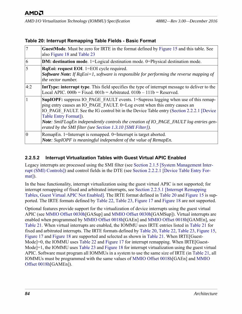
84 Architecture
48882—Rev 3.00—December 2016AMD I/O Virtualization Technology (IOMMU) Specification
2.2.5.2 Interrupt Virtualization Tables with Guest Virtual APIC EnabledLegacy interrupts are processed using the SMI filter (see Section 2.1.5 [System Management Inter-rupt (SMI) Controls]) and control fields in the DTE (see Section 2.2.2.1 [Device Table Entry For-mat]).In the base functionality, interrupt virtualization using the guest virtual APIC is not supported; for interrupt remapping of fixed and arbitrated interrupts, see Section 2.2.5.1 [Interrupt Remapping Tables, Guest Virtual APIC Not Enabled]. The IRTE format defined in Table 20 and Figure 15 is sup-ported. The IRTE formats defined by Table 22, Table 23, Figure 17 and Figure 18 are not supported.Optional features provide support for the virtualization of device interrupts using the guest virtual APIC (see MMIO Offset 0030h[GASup] and MMIO Offset 0030h[GAMSup]). Virtual interrupts are enabled when programmed by MMIO Offset 0018h[GAEn] and MMIO Offset 0018h[GAMEn], see Table 21. When virtual interrupts are enabled, the IOMMU uses IRTE entries listed in Table 21 for fixed and arbitrated interrupts. The IRTE formats defined by Table 20, Table 22, Table 23, Figure 15, Figure 17 and Figure 18 are supported and selected as shown in Table 21. When IRTE[Guest-Mode]=0, the IOMMU uses Table 22 and Figure 17 for interrupt remapping. When IRTE[Guest-Mode]=1, the IOMMU uses Table 23 and Figure 18 for interrupt virtualization using the guest virtual APIC. Software must program all IOMMUs in a system to use the same size of IRTE (in Table 21, all IOMMUs must be programmed with the same values of MMIO Offset 0018h[GAEn] and MMIO Offset 0018h[GAMEn]).
7 GuestMode. Must be zero for IRTE in the format defined by Figure 15 and this table. See also Figure 18 and Table 23
6 DM: destination mode. 1=Logical destination mode. 0=Physical destination mode.5 RqEoi: request EOI. 1=EOI cycle required.
Software Note: If RqEoi=1, software is responsible for performing the reverse mapping of the vector number.
4:2 IntType: interrupt type. This field specifies the type of interrupt message to deliver to the Local APIC. 000b = Fixed. 001b = Arbitrated. 010b – 111b = Reserved.
1 SupIOPF: suppress IO_PAGE_FAULT events. 1=Supress logging when use of this remap-ping entry causes an IO_PAGE_FAULT. 0=Log event when this entry causes an IO_PAGE_FAULT. See the IG control bit in the Device Table entry (Section 2.2.2.1 [Device Table Entry Format]).Note: SmiFLogEn independently controls the creation of IO_PAGE_FAULT log entries gen-erated by the SMI filter (see Section 1.3.10 [SMI Filter]).
0 RemapEn. 1=Interrupt is remapped. 0=Interrupt is target aborted.Note: SupIOPF is meaningful independent of the value of RemapEn.
Table 20: Interrupt Remapping Table Fields - Basic Format
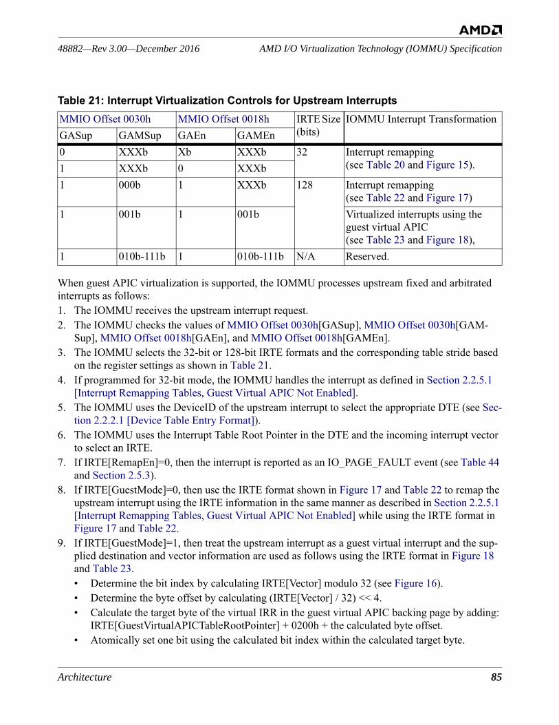
Architecture 85
AMD I/O Virtualization Technology (IOMMU) Specification48882—Rev 3.00—December 2016
When guest APIC virtualization is supported, the IOMMU processes upstream fixed and arbitrated interrupts as follows:1. The IOMMU receives the upstream interrupt request.2. The IOMMU checks the values of MMIO Offset 0030h[GASup], MMIO Offset 0030h[GAM-
Sup], MMIO Offset 0018h[GAEn], and MMIO Offset 0018h[GAMEn].3. The IOMMU selects the 32-bit or 128-bit IRTE formats and the corresponding table stride based
on the register settings as shown in Table 21.4. If programmed for 32-bit mode, the IOMMU handles the interrupt as defined in Section 2.2.5.1
[Interrupt Remapping Tables, Guest Virtual APIC Not Enabled].5. The IOMMU uses the DeviceID of the upstream interrupt to select the appropriate DTE (see Sec-
tion 2.2.2.1 [Device Table Entry Format]).6. The IOMMU uses the Interrupt Table Root Pointer in the DTE and the incoming interrupt vector
to select an IRTE.7. If IRTE[RemapEn]=0, then the interrupt is reported as an IO_PAGE_FAULT event (see Table 44
and Section 2.5.3).8. If IRTE[GuestMode]=0, then use the IRTE format shown in Figure 17 and Table 22 to remap the
upstream interrupt using the IRTE information in the same manner as described in Section 2.2.5.1 [Interrupt Remapping Tables, Guest Virtual APIC Not Enabled] while using the IRTE format in Figure 17 and Table 22.
9. If IRTE[GuestMode]=1, then treat the upstream interrupt as a guest virtual interrupt and the sup-plied destination and vector information are used as follows using the IRTE format in Figure 18 and Table 23.• Determine the bit index by calculating IRTE[Vector] modulo 32 (see Figure 16).• Determine the byte offset by calculating (IRTE[Vector] / 32) << 4.• Calculate the target byte of the virtual IRR in the guest virtual APIC backing page by adding:
IRTE[GuestVirtualAPICTableRootPointer] + 0200h + the calculated byte offset.• Atomically set one bit using the calculated bit index within the calculated target byte.
Table 21: Interrupt Virtualization Controls for Upstream InterruptsMMIO Offset 0030h MMIO Offset 0018h IRTE Size
(bits)IOMMU Interrupt Transformation
GASup GAMSup GAEn GAMEn0 XXXb Xb XXXb 32 Interrupt remapping
(see Table 20 and Figure 15).1 XXXb 0 XXXb1 000b 1 XXXb 128 Interrupt remapping
(see Table 22 and Figure 17)1 001b 1 001b Virtualized interrupts using the
guest virtual APIC (see Table 23 and Figure 18),
1 010b-111b 1 010b-111b N/A Reserved.
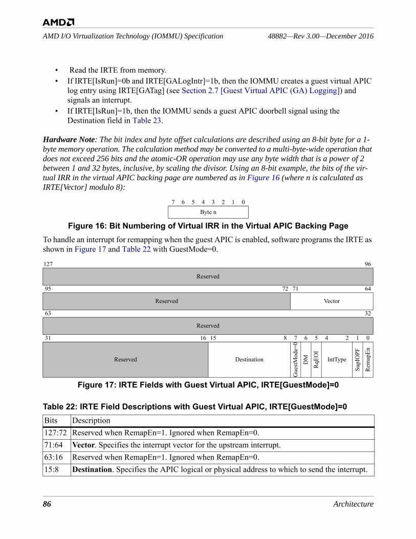
86 Architecture
48882—Rev 3.00—December 2016AMD I/O Virtualization Technology (IOMMU) Specification
• Read the IRTE from memory.• If IRTE[IsRun]=0b and IRTE[GALogIntr]=1b, then the IOMMU creates a guest virtual APIC
log entry using IRTE[GATag] (see Section 2.7 [Guest Virtual APIC (GA) Logging]) and signals an interrupt.
• If IRTE[IsRun]=1b, then the IOMMU sends a guest APIC doorbell signal using the Destination field in Table 23.
Hardware Note: The bit index and byte offset calculations are described using an 8-bit byte for a 1-byte memory operation. The calculation method may be converted to a multi-byte-wide operation that does not exceed 256 bits and the atomic-OR operation may use any byte width that is a power of 2 between 1 and 32 bytes, inclusive, by scaling the divisor. Using an 8-bit example, the bits of the vir-tual IRR in the virtual APIC backing page are numbered as in Figure 16 (where n is calculated as IRTE[Vector] modulo 8):
Figure 16: Bit Numbering of Virtual IRR in the Virtual APIC Backing PageTo handle an interrupt for remapping when the guest APIC is enabled, software programs the IRTE as shown in Figure 17 and Table 22 with GuestMode=0.
Figure 17: IRTE Fields with Guest Virtual APIC, IRTE[GuestMode]=0
7 6 5 4 3 2 1 0Byte n
127 96
Reserved
95 72 71 64
Reserved Vector
63 32
Reserved
31 16 15 8 7 6 5 4 2 1 0
Reserved Destination
Gue
stMod
e=0
DM
RqEO
I
IntTypeSu
pIO
PF
Rem
apEn
Table 22: IRTE Field Descriptions with Guest Virtual APIC, IRTE[GuestMode]=0Bits Description127:72 Reserved when RemapEn=1. Ignored when RemapEn=0.71:64 Vector. Specifies the interrupt vector for the upstream interrupt.63:16 Reserved when RemapEn=1. Ignored when RemapEn=0.15:8 Destination. Specifies the APIC logical or physical address to which to send the interrupt.
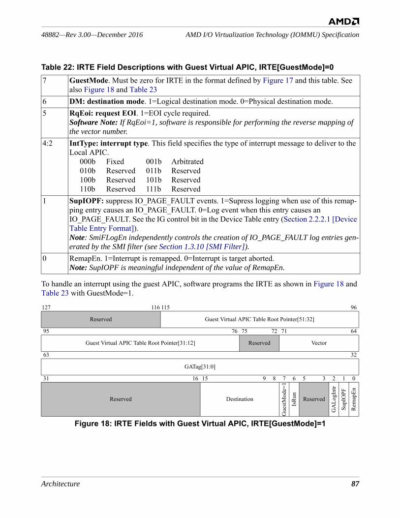
Architecture 87
AMD I/O Virtualization Technology (IOMMU) Specification48882—Rev 3.00—December 2016
To handle an interrupt using the guest APIC, software programs the IRTE as shown in Figure 18 and Table 23 with GuestMode=1.
Figure 18: IRTE Fields with Guest Virtual APIC, IRTE[GuestMode]=1
7 GuestMode. Must be zero for IRTE in the format defined by Figure 17 and this table. See also Figure 18 and Table 23
6 DM: destination mode. 1=Logical destination mode. 0=Physical destination mode.5 RqEoi: request EOI. 1=EOI cycle required.
Software Note: If RqEoi=1, software is responsible for performing the reverse mapping of the vector number.
4:2 IntType: interrupt type. This field specifies the type of interrupt message to deliver to the Local APIC.
000b Fixed 001b Arbitrated010b Reserved 011b Reserved100b Reserved 101b Reserved110b Reserved 111b Reserved
1 SupIOPF: suppress IO_PAGE_FAULT events. 1=Supress logging when use of this remap-ping entry causes an IO_PAGE_FAULT. 0=Log event when this entry causes an IO_PAGE_FAULT. See the IG control bit in the Device Table entry (Section 2.2.2.1 [Device Table Entry Format]).Note: SmiFLogEn independently controls the creation of IO_PAGE_FAULT log entries gen-erated by the SMI filter (see Section 1.3.10 [SMI Filter]).
0 RemapEn. 1=Interrupt is remapped. 0=Interrupt is target aborted.Note: SupIOPF is meaningful independent of the value of RemapEn.
127 116 115 96
Reserved Guest Virtual APIC Table Root Pointer[51:32]
95 76 75 72 71 64
Guest Virtual APIC Table Root Pointer[31:12] Reserved Vector
63 32
GATag[31:0]
31 16 15 9 8 7 6 5 3 2 1 0
Reserved Destination
Gue
stMod
e=1
IsRu
n
Reserved
GA
LogI
ntr
SupI
OPF
Rem
apEn
Table 22: IRTE Field Descriptions with Guest Virtual APIC, IRTE[GuestMode]=0
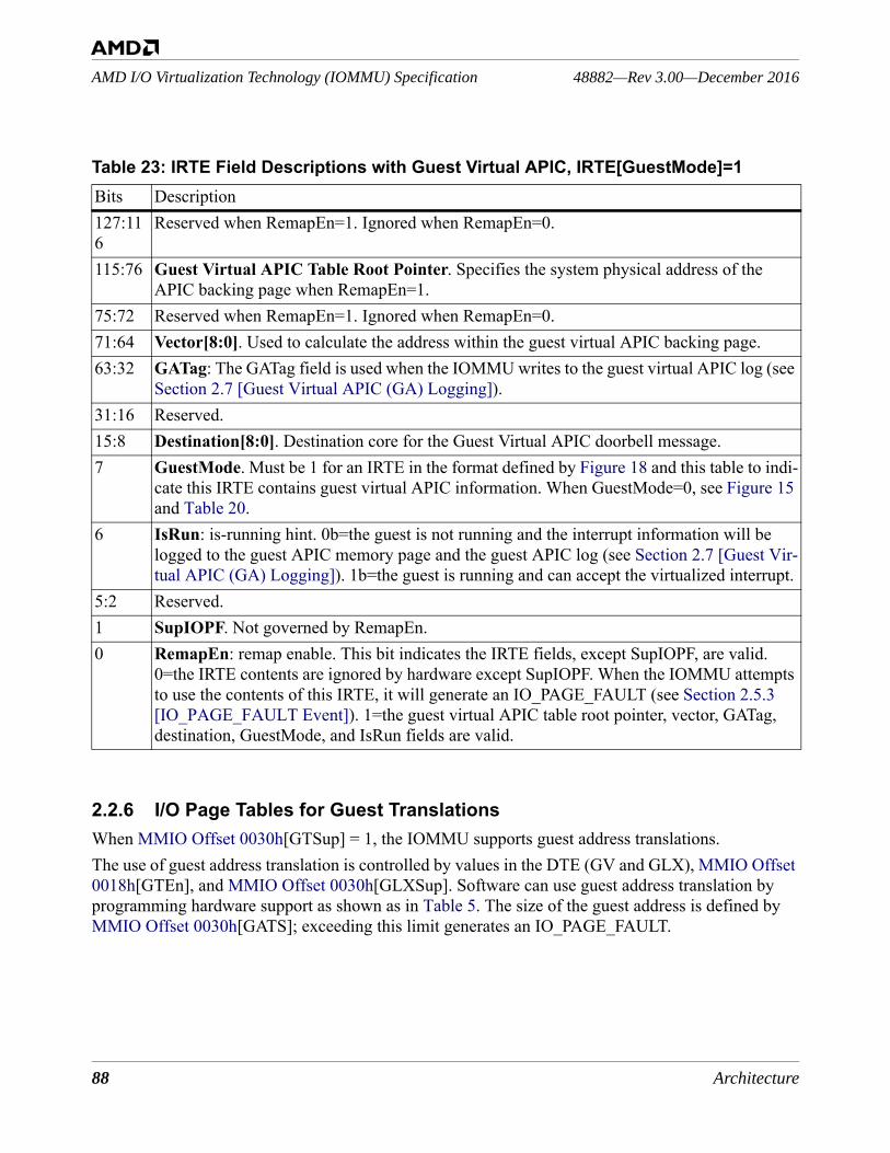
88 Architecture
48882—Rev 3.00—December 2016AMD I/O Virtualization Technology (IOMMU) Specification
2.2.6 I/O Page Tables for Guest TranslationsWhen MMIO Offset 0030h[GTSup] = 1, the IOMMU supports guest address translations.The use of guest address translation is controlled by values in the DTE (GV and GLX), MMIO Offset 0018h[GTEn], and MMIO Offset 0030h[GLXSup]. Software can use guest address translation by programming hardware support as shown as in Table 5. The size of the guest address is defined by MMIO Offset 0030h[GATS]; exceeding this limit generates an IO_PAGE_FAULT.
Table 23: IRTE Field Descriptions with Guest Virtual APIC, IRTE[GuestMode]=1Bits Description127:116
Reserved when RemapEn=1. Ignored when RemapEn=0.
115:76 Guest Virtual APIC Table Root Pointer. Specifies the system physical address of the APIC backing page when RemapEn=1.
75:72 Reserved when RemapEn=1. Ignored when RemapEn=0. 71:64 Vector[8:0]. Used to calculate the address within the guest virtual APIC backing page.63:32 GATag: The GATag field is used when the IOMMU writes to the guest virtual APIC log (see
Section 2.7 [Guest Virtual APIC (GA) Logging]).31:16 Reserved.15:8 Destination[8:0]. Destination core for the Guest Virtual APIC doorbell message.7 GuestMode. Must be 1 for an IRTE in the format defined by Figure 18 and this table to indi-
cate this IRTE contains guest virtual APIC information. When GuestMode=0, see Figure 15 and Table 20.
6 IsRun: is-running hint. 0b=the guest is not running and the interrupt information will be logged to the guest APIC memory page and the guest APIC log (see Section 2.7 [Guest Vir-tual APIC (GA) Logging]). 1b=the guest is running and can accept the virtualized interrupt.
5:2 Reserved.1 SupIOPF. Not governed by RemapEn.0 RemapEn: remap enable. This bit indicates the IRTE fields, except SupIOPF, are valid.
0=the IRTE contents are ignored by hardware except SupIOPF. When the IOMMU attempts to use the contents of this IRTE, it will generate an IO_PAGE_FAULT (see Section 2.5.3 [IO_PAGE_FAULT Event]). 1=the guest virtual APIC table root pointer, vector, GATag, destination, GuestMode, and IsRun fields are valid.
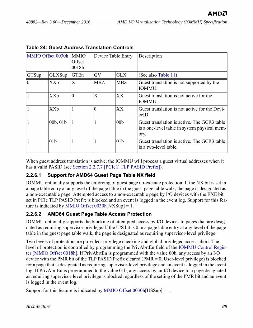
Architecture 89
AMD I/O Virtualization Technology (IOMMU) Specification48882—Rev 3.00—December 2016
When guest address translation is active, the IOMMU will process a guest virtual addresses when it has a valid PASID (see Section 2.2.7.7 [PCIe® TLP PASID Prefix]).2.2.6.1 Support for AMD64 Guest Page Table NX fieldIOMMU optionally supports the enforcing of guest page no-execute protection. If the NX bit is set in a page table entry at any level of the page table in the guest page table walk, the page is designated as a non-executable page. Attempted access to a non-executable page by I/O devices with the EXE bit set in PCIe TLP PASID Prefix is blocked and an event is logged in the event log. Support for this fea-ture is indicated by MMIO Offset 0030h[NXSup] = 1.2.2.6.2 AMD64 Guest Page Table Access ProtectionIOMMU optionally supports the blocking of attempted access by I/O devices to pages that are desig-nated as requiring supervisor privilege. If the U/S bit is 0 in a page table entry at any level of the page table in the guest page table walk, the page is designated as requiring supervisor-level privilege.Two levels of protection are provided: privilege checking and global privileged access abort. The level of protection is controlled by programming the PrivAbrtEn field of the IOMMU Control Regis-ter [MMIO Offset 0018h]. If PrivAbrtEn is programmed with the value 00b, any access by an I/O device with the PMR bit of the TLP PASID Prefix cleared (PMR = 0; User-level privilege) is blocked for a page that is designated as requiring supervisor-level privilege and an event is logged in the event log. If PrivAbrtEn is programmed to the value 01b, any access by an I/O device to a page designated as requiring supervisor-level privilege is blocked regardless of the setting of the PMR bit and an event is logged in the event log.Support for this feature is indicated by MMIO Offset 0030h[USSup] = 1.
Table 24: Guest Address Translation ControlsMMIO Offset 0030h MMIO
Offset 0018h
Device Table Entry Description
GTSup GLXSup GTEn GV GLX (See also Table 11)0 XXb X MBZ MBZ Guest translation is not supported by the
IOMMU.1 XXb 0 X XX Guest translation is not active for the
IOMMU.1 XXb 1 0 XX Guest translation is not active for the Devi-
ceID.1 00b, 01b 1 1 00b Guest translation is active. The GCR3 table
is a one-level table in system physical mem-ory.
1 01b 1 1 01b Guest translation is active. The GCR3 table is a two-level table.
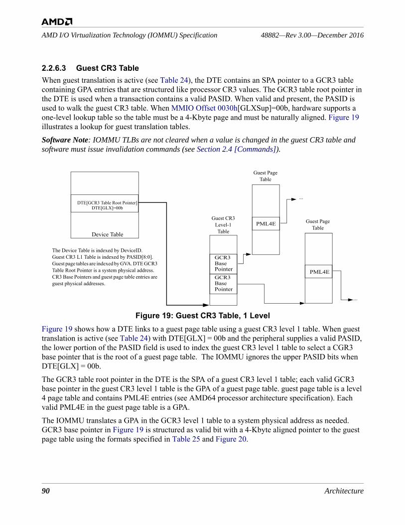
90 Architecture
48882—Rev 3.00—December 2016AMD I/O Virtualization Technology (IOMMU) Specification
2.2.6.3 Guest CR3 TableWhen guest translation is active (see Table 24), the DTE contains an SPA pointer to a GCR3 table containing GPA entries that are structured like processor CR3 values. The GCR3 table root pointer in the DTE is used when a transaction contains a valid PASID. When valid and present, the PASID is used to walk the guest CR3 table. When MMIO Offset 0030h[GLXSup]=00b, hardware supports a one-level lookup table so the table must be a 4-Kbyte page and must be naturally aligned. Figure 19 illustrates a lookup for guest translation tables. Software Note: IOMMU TLBs are not cleared when a value is changed in the guest CR3 table and software must issue invalidation commands (see Section 2.4 [Commands]).
Figure 19: Guest CR3 Table, 1 LevelFigure 19 shows how a DTE links to a guest page table using a guest CR3 level 1 table. When guest translation is active (see Table 24) with DTE[GLX] = 00b and the peripheral supplies a valid PASID, the lower portion of the PASID field is used to index the guest CR3 level 1 table to select a CGR3 base pointer that is the root of a guest page table. The IOMMU ignores the upper PASID bits when DTE[GLX] = 00b.The GCR3 table root pointer in the DTE is the SPA of a guest CR3 level 1 table; each valid GCR3 base pointer in the guest CR3 level 1 table is the GPA of a guest page table. guest page table is a level 4 page table and contains PML4E entries (see AMD64 processor architecture specification). Each valid PML4E in the guest page table is a GPA.The IOMMU translates a GPA in the GCR3 level 1 table to a system physical address as needed. GCR3 base pointer in Figure 19 is structured as valid bit with a 4-Kbyte aligned pointer to the guest page table using the formats specified in Table 25 and Figure 20.
Guest CR3Level-1 TableDevice Table
GCR3 PML4E
DTE[GCR3 Table Root Pointer]
...
BasePointer
Guest PageTable
PML4E
...
Guest PageTable
GCR3 BasePointer
DTE[GLX]=00b
The Device Table is indexed by DeviceID.Guest CR3 L1 Table is indexed by PASID[8:0]. Guest page tables are indexed by GVA. DTE GCR3 Table Root Pointer is a system physical address.CR3 Base Pointers and guest page table entries are guest physical addresses.

Architecture 91
AMD I/O Virtualization Technology (IOMMU) Specification48882—Rev 3.00—December 2016
The structure in Figure 19 on page 90 may be used when software programs DTE[GLX] = 00b. In this mode, PASID values up to 9 bits long are supported . When software programs DTE[GLX] = 01b, PASID values up to18 bits long are supported . The two-level structure in Figure 21 will be used. Software may program DTE[GLX]=10b to enable a three-level structure used to support larger PASID widths up to 20 bits.
Table 25: AMD64 Guest CR3 Level-1 Table FormatByte Offset Guest CR3 Base Table Contents0 GCR3 Base Pointer entry for PASID0 (GPA)8 CGR3 Base Pointer entry for PASID1 (GPA)
16 GCR3 Base Pointer entry for PASID2 (GPA)
... ...4088 GCR3 Base Pointer entry for PASID511 (GPA)
63 52 51 32
Reserved GCR3 Base Page Pointer[51:32]
31 12 11 5 4 3 2 1 0
Guest Page Pointer[31:12] Reserved Ign Rsvd V
Figure 20: AMD64 GCR3 Base Pointer Entry Format
Table 26: AMD64 GCR3 Base Pointer Entry FieldsBits Description63:52 Reserved when V=1. Ignored when V=0. 51:12 Guest Page Table Pointer. Specifies a GPA base table address when V=1.11:5 Reserved when V=1. Ignored when V=0. 4:3 Ignored. The PCD and PWT bits used in the processor CR3 register are ignored by the
IOMMU.2:1 Reserved when V=1. Ignored when V=0.0 V: Valid. Valid bit for the GCR3 base table pointer. 0=the GCR3 base pointer is ignored by
hardware. 1=the GCR3 base pointer is the GPA of the root page of a guest page table.
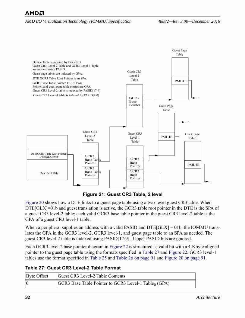
92 Architecture
48882—Rev 3.00—December 2016AMD I/O Virtualization Technology (IOMMU) Specification
Figure 21: Guest CR3 Table, 2 levelFigure 20 shows how a DTE links to a guest page table using a two-level guest CR3 table. When DTE[GLX]=01b and guest translation is active, the GCR3 table root pointer in the DTE is the SPA of a guest CR3 level-2 table; each valid GCR3 base table pointer in the guest CR3 level-2 table is the GPA of a guest CR3 level-1 table.When a peripheral supplies an address with a valid PASID and DTE[GLX] = 01b, the IOMMU trans-lates the GPA in the GCR3 level-2, GCR3 level-1, and guest page table to an SPA as needed. The guest CR3 level-2 table is indexed using PASID[17:9] . Upper PASID bits are ignored.Each GCR3 level-2 base pointer diagram in Figure 22 is structured as valid bit with a 4-Kbyte aligned pointer to the guest page table using the formats specified in Table 27 and Figure 22. GCR3 level-1 tables use the format specified in Table 25 and Table 26 on page 91 and Figure 20 on page 91.
Table 27: Guest CR3 Level-2 Table FormatByte Offset Guest CR3 Level-2 Table Contents0 GCR3 Base Table Pointer to GCR3 Level-1 Table0 (GPA)
Guest CR3Level-2 Table
Device TableGCR3
PML4E
DTE[GCR3 Table Root Pointer]
...
Base TablePointer
Device Table is indexed by DeviceID.
Guest PageTablePML4E
...
Guest PageTable
GCR3 Base TablePointer
Guest CR3 Level-2 Table and GCR3 Level-1 Table
Guest page tables are indexed by GVA.
DTE[GLX]=01b
Guest CR3Level-1 Table
GCR3 BasePointer
GCR3 BasePointer
Guest CR3Level-1 Table
GCR3 BasePointer
are indexed using PASID.
PML4E
Guest PageTable
...
DTE GCR3 Table Root Pointer is an SPA.
Guest CR3 Level-2 table is indexed by PASID[17:9]Guest CR3 Level-1 table is indexed by PASID[8:0]
GCR3 Base Table Pointer, GCR3 BasePointer, and guest page table entries are GPA.
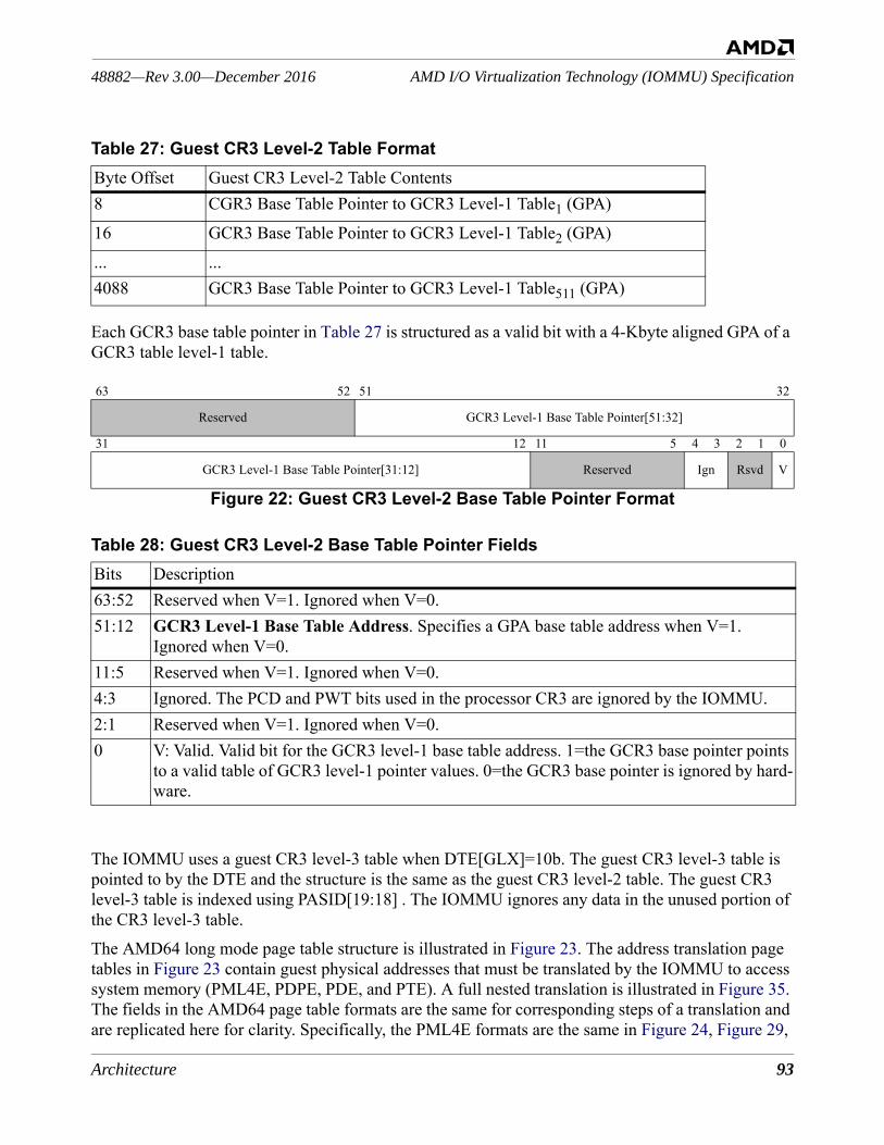
Architecture 93
AMD I/O Virtualization Technology (IOMMU) Specification48882—Rev 3.00—December 2016
Each GCR3 base table pointer in Table 27 is structured as a valid bit with a 4-Kbyte aligned GPA of a GCR3 table level-1 table.
The IOMMU uses a guest CR3 level-3 table when DTE[GLX]=10b. The guest CR3 level-3 table is pointed to by the DTE and the structure is the same as the guest CR3 level-2 table. The guest CR3 level-3 table is indexed using PASID[19:18] . The IOMMU ignores any data in the unused portion of the CR3 level-3 table. The AMD64 long mode page table structure is illustrated in Figure 23. The address translation page tables in Figure 23 contain guest physical addresses that must be translated by the IOMMU to access system memory (PML4E, PDPE, PDE, and PTE). A full nested translation is illustrated in Figure 35. The fields in the AMD64 page table formats are the same for corresponding steps of a translation and are replicated here for clarity. Specifically, the PML4E formats are the same in Figure 24, Figure 29,
8 CGR3 Base Table Pointer to GCR3 Level-1 Table1 (GPA)
16 GCR3 Base Table Pointer to GCR3 Level-1 Table2 (GPA)
... ...4088 GCR3 Base Table Pointer to GCR3 Level-1 Table511 (GPA)
63 52 51 32
Reserved GCR3 Level-1 Base Table Pointer[51:32]
31 12 11 5 4 3 2 1 0
GCR3 Level-1 Base Table Pointer[31:12] Reserved Ign Rsvd V
Figure 22: Guest CR3 Level-2 Base Table Pointer Format
Table 28: Guest CR3 Level-2 Base Table Pointer FieldsBits Description63:52 Reserved when V=1. Ignored when V=0.51:12 GCR3 Level-1 Base Table Address. Specifies a GPA base table address when V=1.
Ignored when V=0.11:5 Reserved when V=1. Ignored when V=0.4:3 Ignored. The PCD and PWT bits used in the processor CR3 are ignored by the IOMMU.2:1 Reserved when V=1. Ignored when V=0.0 V: Valid. Valid bit for the GCR3 level-1 base table address. 1=the GCR3 base pointer points
to a valid table of GCR3 level-1 pointer values. 0=the GCR3 base pointer is ignored by hard-ware.
Table 27: Guest CR3 Level-2 Table FormatByte Offset Guest CR3 Level-2 Table Contents
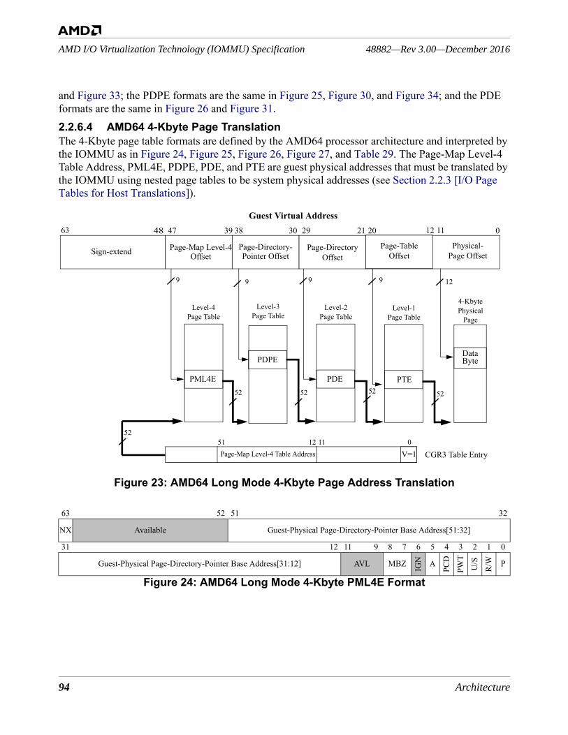
94 Architecture
48882—Rev 3.00—December 2016AMD I/O Virtualization Technology (IOMMU) Specification
and Figure 33; the PDPE formats are the same in Figure 25, Figure 30, and Figure 34; and the PDE formats are the same in Figure 26 and Figure 31.2.2.6.4 AMD64 4-Kbyte Page TranslationThe 4-Kbyte page table formats are defined by the AMD64 processor architecture and interpreted by the IOMMU as in Figure 24, Figure 25, Figure 26, Figure 27, and Table 29. The Page-Map Level-4 Table Address, PML4E, PDPE, PDE, and PTE are guest physical addresses that must be translated by the IOMMU using nested page tables to be system physical addresses (see Section 2.2.3 [I/O Page Tables for Host Translations]).
Figure 23: AMD64 Long Mode 4-Kbyte Page Address Translation
63 52 51 32
NX Available Guest-Physical Page-Directory-Pointer Base Address[51:32]
31 12 11 9 8 7 6 5 4 3 2 1 0
Guest-Physical Page-Directory-Pointer Base Address[31:12] AVL MBZ IGN A
PCD
PWT
U/S
R/W P
Figure 24: AMD64 Long Mode 4-Kbyte PML4E Format
Guest Virtual Address
Page-Directory- Page-DirectoryOffset
0202129303839474863
99
52
1251
CGR3 Table Entry
Level-4Page Table
4-Kbyte Physical
Page
Physical-Page Offset
Page-Map Level-4 Table Address11
Page-Map Level-4
9
52
Level-2Page Table
Sign-extend
PML4E PDE
Offset Pointer Offset
52
PDPE
Level-3Page Table
9
52
Level-1Page Table
PTE
1112
Page-TableOffset
12
V=10
52
DataByte
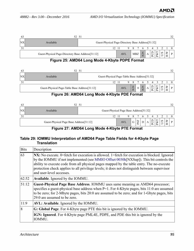
Architecture 95
AMD I/O Virtualization Technology (IOMMU) Specification48882—Rev 3.00—December 2016
63 52 51 32
NX Available Guest-Physical Page-Directory Base Address[51:32]
31 12 11 9 8 7 6 5 4 3 2 1 0
Guest-Physical Page-Directory Base Address[31:12] AVL MBZ IGN A
PCD
PWT
U/S
R/W P
Figure 25: AMD64 Long Mode 4-Kbyte PDPE Format
63 52 51 32
NX Available Guest-Physical Page-Table Base Address[51:32]
31 12 11 9 8 7 6 5 4 3 2 1 0
Guest-Physical Page-Table Base Address[31:12] AVL IGN 0 IGN A
PCD
PWT
U/S
R/W P
Figure 26: AMD64 Long Mode 4-Kbyte PDE Format
63 52 51 32
NX Available Guest-Physical Page Base Address[51:32]
31 12 11 9 8 7 6 5 4 3 2 1 0
Guest-Physical Page Base Address[31:12] AVL G PAT D A
PCD
PWT
U/S
R/W P
Figure 27: AMD64 Long Mode 4-Kbyte PTE Format
Table 29: IOMMU Interpretation of AMD64 Page Table Fields for 4-Kbyte Page Translation
Bits Description63 NX: No execute. 0=fetch for execution is allowed. 1=fetch for execution is blocked. Ignored
by the IOMMU if not implemented (see MMIO Offset 0030h[NXSup]). This bit controls the ability to execute code from all physical pages mapped by the table entry. The no-execute protection check applies to all privilege levels; it does not distinguish between supervisor and user-level accesses.
62:52 Available. Ignored by the IOMMU.51:12 Guest-Physical Page Base Address. IOMMU uses same meaning as AMD64 processor;
specifies a guest-physical base address when P=1. For 4-Kbyte pages, bits 11:0 are assumed to be zero; for 2-Mbyte pages, bits 20:0 are assumed to be zero; and for 1-Gbyte pages, bits 29:0 are assumed to be zero.
11:9 AVL: Available. Ignored by the IOMMU.8 G: Global Page. For 4-Kbyte page PTE this bit is ignored by the IOMMU.
IGN: Ignored. For 4-Kbyte page PML4E, PDPE, and PDE this bit is ignored by the IOMMU.
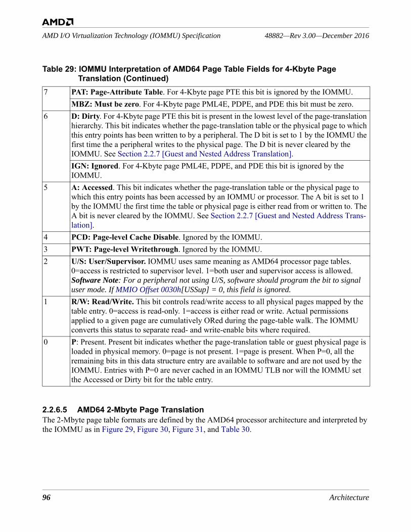
96 Architecture
48882—Rev 3.00—December 2016AMD I/O Virtualization Technology (IOMMU) Specification
2.2.6.5 AMD64 2-Mbyte Page TranslationThe 2-Mbyte page table formats are defined by the AMD64 processor architecture and interpreted by the IOMMU as in Figure 29, Figure 30, Figure 31, and Table 30.
7 PAT: Page-Attribute Table. For 4-Kbyte page PTE this bit is ignored by the IOMMU.MBZ: Must be zero. For 4-Kbyte page PML4E, PDPE, and PDE this bit must be zero.
6 D: Dirty. For 4-Kbyte page PTE this bit is present in the lowest level of the page-translation hierarchy. This bit indicates whether the page-translation table or the physical page to which this entry points has been written to by a peripheral. The D bit is set to 1 by the IOMMU the first time the a peripheral writes to the physical page. The D bit is never cleared by the IOMMU. See Section 2.2.7 [Guest and Nested Address Translation]. IGN: Ignored. For 4-Kbyte page PML4E, PDPE, and PDE this bit is ignored by the IOMMU.
5 A: Accessed. This bit indicates whether the page-translation table or the physical page to which this entry points has been accessed by an IOMMU or processor. The A bit is set to 1 by the IOMMU the first time the table or physical page is either read from or written to. The A bit is never cleared by the IOMMU. See Section 2.2.7 [Guest and Nested Address Trans-lation].
4 PCD: Page-level Cache Disable. Ignored by the IOMMU. 3 PWT: Page-level Writethrough. Ignored by the IOMMU.2 U/S: User/Supervisor. IOMMU uses same meaning as AMD64 processor page tables.
0=access is restricted to supervisor level. 1=both user and supervisor access is allowed.Software Note: For a peripheral not using U/S, software should program the bit to signal user mode. If MMIO Offset 0030h[USSup] = 0, this field is ignored.
1 R/W: Read/Write. This bit controls read/write access to all physical pages mapped by the table entry. 0=access is read-only. 1=access is either read or write. Actual permissions applied to a given page are cumulatively ORed during the page-table walk. The IOMMU converts this status to separate read- and write-enable bits where required.
0 P: Present. Present bit indicates whether the page-translation table or guest physical page is loaded in physical memory. 0=page is not present. 1=page is present. When P=0, all the remaining bits in this data structure entry are available to software and are not used by the IOMMU. Entries with P=0 are never cached in an IOMMU TLB nor will the IOMMU set the Accessed or Dirty bit for the table entry.
Table 29: IOMMU Interpretation of AMD64 Page Table Fields for 4-Kbyte Page Translation (Continued)
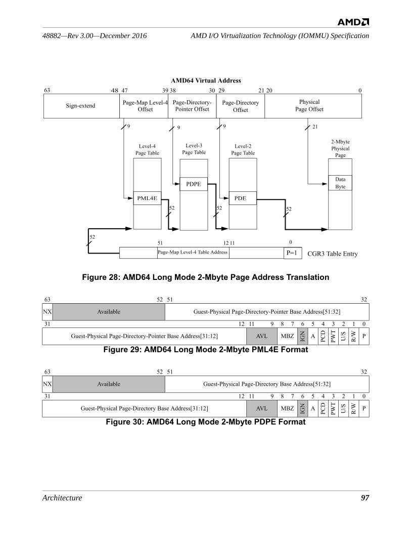
Architecture 97
AMD I/O Virtualization Technology (IOMMU) Specification48882—Rev 3.00—December 2016
Figure 28: AMD64 Long Mode 2-Mbyte Page Address Translation
63 52 51 32
NX Available Guest-Physical Page-Directory-Pointer Base Address[51:32]
31 12 11 9 8 7 6 5 4 3 2 1 0
Guest-Physical Page-Directory-Pointer Base Address[31:12] AVL MBZ IGN A
PCD
PWT
U/S
R/W P
Figure 29: AMD64 Long Mode 2-Mbyte PML4E Format
63 52 51 32
NX Available Guest-Physical Page-Directory Base Address[51:32]
31 12 11 9 8 7 6 5 4 3 2 1 0
Guest-Physical Page-Directory Base Address[31:12] AVL MBZ IGN A
PCD
PWT
U/S
R/W P
Figure 30: AMD64 Long Mode 2-Mbyte PDPE Format
AMD64 Virtual Address
Page-Directory- Page-DirectoryOffset
0202129303839474863
DataByte
219
52
1251
CGR3 Table Entry
Level-4Page Table
2-Mbyte Physical
Page
PhysicalPage Offset
Page-Map Level-4 Table Address
11
Page-Map Level-4
9
52
Level-2Page Table
Sign-extend
PML4E PDE
Offset Pointer Offset
52
PDPE
Level-3Page Table
9
P=10
52
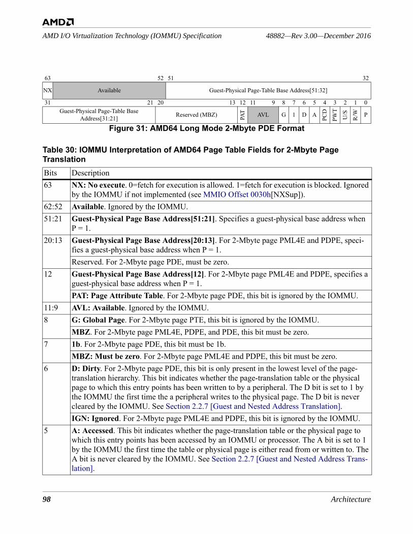
98 Architecture
48882—Rev 3.00—December 2016AMD I/O Virtualization Technology (IOMMU) Specification
63 52 51 32
NX Available Guest-Physical Page-Table Base Address[51:32]
31 21 20 13 12 11 9 8 7 6 5 4 3 2 1 0Guest-Physical Page-Table Base
Address[31:21] Reserved (MBZ) PAT AVL G 1 D A
PCD
PWT
U/S
R/W P
Figure 31: AMD64 Long Mode 2-Mbyte PDE Format
Table 30: IOMMU Interpretation of AMD64 Page Table Fields for 2-Mbyte Page TranslationBits Description63 NX: No execute. 0=fetch for execution is allowed. 1=fetch for execution is blocked. Ignored
by the IOMMU if not implemented (see MMIO Offset 0030h[NXSup]). 62:52 Available. Ignored by the IOMMU.51:21 Guest-Physical Page Base Address[51:21]. Specifies a guest-physical base address when
P = 1.20:13 Guest-Physical Page Base Address[20:13]. For 2-Mbyte page PML4E and PDPE, speci-
fies a guest-physical base address when P = 1.Reserved. For 2-Mbyte page PDE, must be zero.
12 Guest-Physical Page Base Address[12]. For 2-Mbyte page PML4E and PDPE, specifies a guest-physical base address when P = 1.PAT: Page Attribute Table. For 2-Mbyte page PDE, this bit is ignored by the IOMMU.
11:9 AVL: Available. Ignored by the IOMMU.8 G: Global Page. For 2-Mbyte page PTE, this bit is ignored by the IOMMU.
MBZ. For 2-Mbyte page PML4E, PDPE, and PDE, this bit must be zero.7 1b. For 2-Mbyte page PDE, this bit must be 1b.
MBZ: Must be zero. For 2-Mbyte page PML4E and PDPE, this bit must be zero.6 D: Dirty. For 2-Mbyte page PDE, this bit is only present in the lowest level of the page-
translation hierarchy. This bit indicates whether the page-translation table or the physical page to which this entry points has been written to by a peripheral. The D bit is set to 1 by the IOMMU the first time the a peripheral writes to the physical page. The D bit is never cleared by the IOMMU. See Section 2.2.7 [Guest and Nested Address Translation].IGN: Ignored. For 2-Mbyte page PML4E and PDPE, this bit is ignored by the IOMMU.
5 A: Accessed. This bit indicates whether the page-translation table or the physical page to which this entry points has been accessed by an IOMMU or processor. The A bit is set to 1 by the IOMMU the first time the table or physical page is either read from or written to. The A bit is never cleared by the IOMMU. See Section 2.2.7 [Guest and Nested Address Trans-lation].
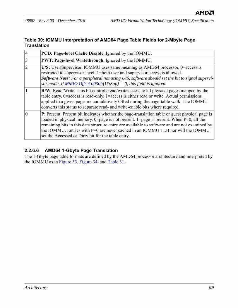
Architecture 99
AMD I/O Virtualization Technology (IOMMU) Specification48882—Rev 3.00—December 2016
2.2.6.6 AMD64 1-Gbyte Page TranslationThe 1-Gbyte page table formats are defined by the AMD64 processor architecture and interpreted by the IOMMU as in Figure 33, Figure 34, and Table 31.
4 PCD: Page-level Cache Disable. Ignored by the IOMMU. 3 PWT: Page-level Writethrough. Ignored by the IOMMU.2 U/S: User/Supervisor. IOMMU uses same meaning as AMD64 processor. 0=access is
restricted to supervisor level. 1=both user and supervisor access is allowed.Software Note: For a peripheral not using U/S, software should set the bit to signal supervi-sor mode. If MMIO Offset 0030h[USSup] = 0, this field is ignored.
1 R/W: Read/Write. This bit controls read/write access to all physical pages mapped by the table entry. 0=access is read-only. 1=access is either read or write. Actual permissions applied to a given page are cumulatively ORed during the page-table walk. The IOMMU converts this status to separate read- and write-enable bits where required.
0 P: Present. Present bit indicates whether the page-translation table or guest physical page is loaded in physical memory. 0=page is not present. 1=page is present. When P=0, all the remaining bits in this data structure entry are available to software and are not examined by the IOMMU. Entries with P=0 are never cached in an IOMMU TLB nor will the IOMMU set the Accessed or Dirty bit for the table entry.
Table 30: IOMMU Interpretation of AMD64 Page Table Fields for 2-Mbyte Page Translation
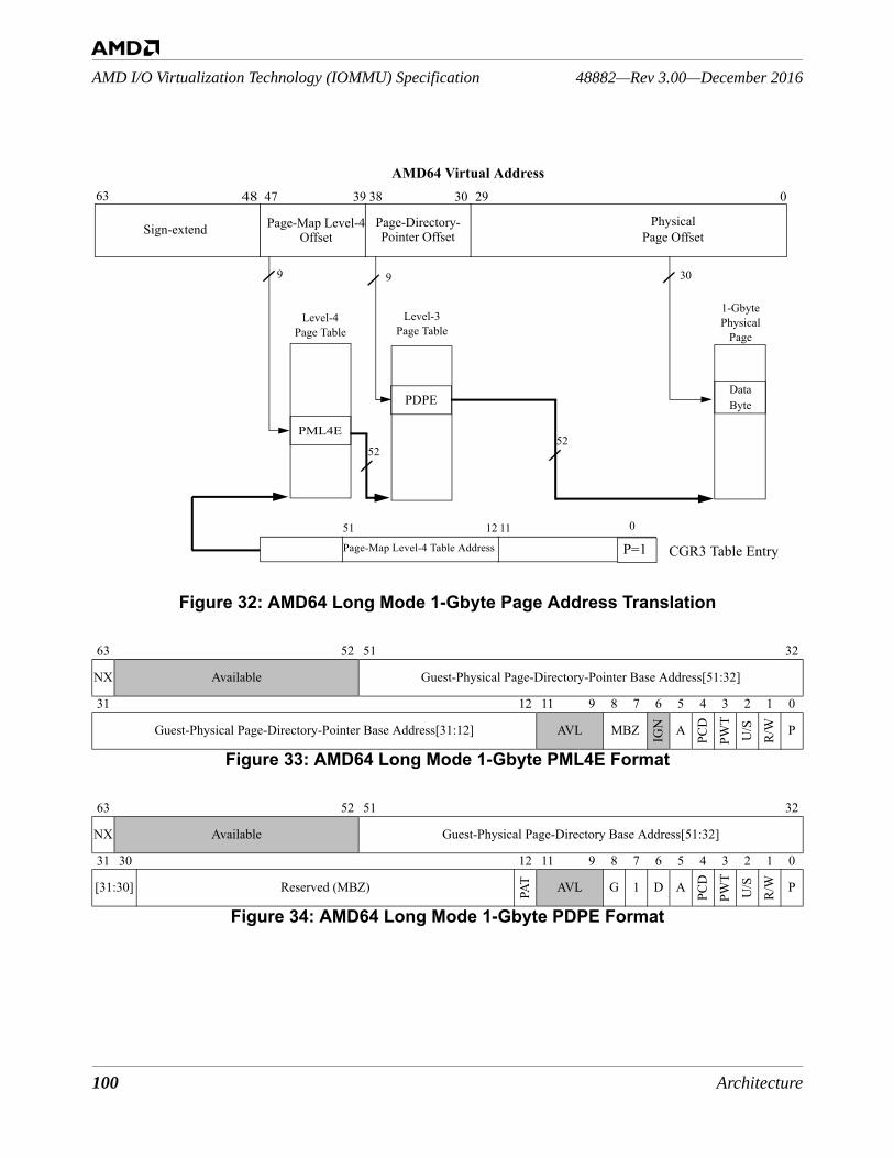
100 Architecture
48882—Rev 3.00—December 2016AMD I/O Virtualization Technology (IOMMU) Specification
Figure 32: AMD64 Long Mode 1-Gbyte Page Address Translation
63 52 51 32
NX Available Guest-Physical Page-Directory-Pointer Base Address[51:32]
31 12 11 9 8 7 6 5 4 3 2 1 0
Guest-Physical Page-Directory-Pointer Base Address[31:12] AVL MBZ IGN A
PCD
PWT
U/S
R/W P
Figure 33: AMD64 Long Mode 1-Gbyte PML4E Format
63 52 51 32
NX Available Guest-Physical Page-Directory Base Address[51:32]
31 30 12 11 9 8 7 6 5 4 3 2 1 0
[31:30] Reserved (MBZ) PAT AVL G 1 D A
PCD
PWT
U/S
R/W P
Figure 34: AMD64 Long Mode 1-Gbyte PDPE Format
AMD64 Virtual Address
Page-Directory-
029303839474863
DataByte
309
52
1251
CGR3 Table Entry
Level-4Page Table
1-Gbyte Physical
Page
PhysicalPage Offset
Page-Map Level-4 Table Address
11
Page-Map Level-4Sign-extend
PML4E
Offset Pointer Offset
52
PDPE
Level-3Page Table
9
P=10

Architecture 101
AMD I/O Virtualization Technology (IOMMU) Specification48882—Rev 3.00—December 2016
Table 31: IOMMU Interpretation of AMD64 Long Mode 1-Gbyte Page Table FieldsBits Description from AMD64 processor specification63 NX: No execute. 0=fetch for execution is allowed. 1=fetch for execution is blocked. Ignored
by the IOMMU if not implemented (see MMIO Offset 0030h[NXSup]). 62:52 Available. Ignored by the IOMMU.51:31 Guest-Physical Page Base Address[51:31]. For 1-Gbyte PML4E and PDPE, specifies a
guest-physical base address when P=1.29:13 Guest-Physical Page Base Address[29:13]. For 1-Gbyte PML4E, specifies a guest-physi-
cal base address when P=1.Reserved. For 1-Gbyte page PDPE, must be zero
12 Guest-Physical Page Base Address[12]. For 1-Gbyte PML4E, specifies a guest-physical base address when P = 1.PAT: Page Attribute Table. For 1-Gbyte page PDPE this bit is ignored by the IOMMU.
11:9 AVL: Available. Ignored by the IOMMU.8 G: Global Page. For 1-Gbyte page PDPE this bit is ignored by the IOMMU.
MBZ. For 1-Gbyte page PML4E this bit must be zero.7 1b. For 1-Gbyte page PDPE this bit must be 1b.
MBZ: Must be zero. For 1-Gbyte page PML4E this bit must be zero.6 D: Dirty. For 1-Gbyte page PDPE, this bit is only present in the lowest level of the page-
translation hierarchy. This bit indicates whether the page-translation table or the physical page to which this entry points has been written to by a peripheral. The D bit is set to 1 by the IOMMU the first time the a peripheral writes to the physical page. The D bit is never cleared by the IOMMU. See Section 2.2.7 [Guest and Nested Address Translation].IGN: Ignored. For 1-Gbyte page PML4E, this bit is ignored by the IOMMU.
5 A: Accessed. IOMMU uses same meaning as AMD64 processor. This bit indicates whether the page-translation table or the physical page to which this entry points has been accessed by an IOMMU or processor. The A bit is set to 1 by the IOMMU the first time the table or physical page is either read from or written to. The A bit is never cleared by the IOMMU. See Section 2.2.7 [Guest and Nested Address Translation].
4 PCD: Page-level Cache Disable. Ignored by the IOMMU. 3 PWT: Page-level Writethrough. Ignored by the IOMMU.2 U/S: User/Supervisor. IOMMU uses same meaning as AMD64 processor. 0 = access is
restricted to supervisor level. 1 = both user and supervisor access is allowed.Software Note: For a peripheral not using U/S, software should set the bit to select supervi-sor mode. If MMIO Offset 0030h[USSup] = 0, this field is ignored.
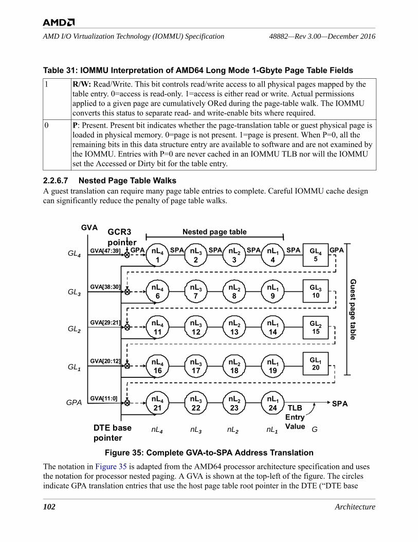
102 Architecture
48882—Rev 3.00—December 2016AMD I/O Virtualization Technology (IOMMU) Specification
2.2.6.7 Nested Page Table WalksA guest translation can require many page table entries to complete. Careful IOMMU cache design can significantly reduce the penalty of page table walks.
Figure 35: Complete GVA-to-SPA Address TranslationThe notation in Figure 35 is adapted from the AMD64 processor architecture specification and uses the notation for processor nested paging. A GVA is shown at the top-left of the figure. The circles indicate GPA translation entries that use the host page table root pointer in the DTE (“DTE base
1 R/W: Read/Write. This bit controls read/write access to all physical pages mapped by the table entry. 0=access is read-only. 1=access is either read or write. Actual permissions applied to a given page are cumulatively ORed during the page-table walk. The IOMMU converts this status to separate read- and write-enable bits where required.
0 P: Present. Present bit indicates whether the page-translation table or guest physical page is loaded in physical memory. 0=page is not present. 1=page is present. When P=0, all the remaining bits in this data structure entry are available to software and are not examined by the IOMMU. Entries with P=0 are never cached in an IOMMU TLB nor will the IOMMU set the Accessed or Dirty bit for the table entry.
Table 31: IOMMU Interpretation of AMD64 Long Mode 1-Gbyte Page Table Fields
nL41
nL23
nL32
nL14
nL46
nL28
nL37
nL19
nL411
nL213
nL312
nL114
nL416
nL218
nL317
nL119
nL421
nL223
nL322
Nested page tableGVA
GL310
GL215
GL120
GL45
SPA
GCR3 pointer
GVA[11:0]
GVA[20:12]
GVA[29:21]
GVA[38:30]
GVA[47:39]
DTE base pointer
TLB Entry Value
GPA
nL124
SPA SPA SPA SPA GPA
Guest page table
GL1
GL2
GL3
GL4
GPA
nL4 nL3 nL2 nL1 G
Architecture 103
AMD I/O Virtualization Technology (IOMMU) Specification48882—Rev 3.00—December 2016
pointer” in the figure). The square entries are GPA entries that are obtained using the guest translation tables pointed to from the GCR3 Table. The figure shows an example of the nested paging translation process when using AMD64 4K Guest and Host page tables. The square entries on the right edge of the figure correspond to Figure 24, Figure 25, Figure 26, and Figure 27. The number of rows corre-sponds to the number of levels in the guest page table and is smaller when large pages are used. The number of circles on each row may vary depending on the size of the host pages and whether level skipping is used. In the ideal case, an IOMMU TLB cache entry is found containing the required SPA and the translation is complete. If there is no TLB cache hit, the IOMMU must perform a complete page table walk. The GVA must be processed through four layers of guest address translations in the guest physical address space; this is illustrated down the diagram. Each GPA must be translated into the system physical address space to obtain a series of intermediate translation records, illustrated across the diagram.
2.2.7 Guest and Nested Address TranslationThe IOMMU supports host nested address translation and optionally supports guest address transla-tion. 2.2.7.1 Combining Guest and Host Address TranslationThe guest and nested (host) translation can be operated in four basic combinations: disabled, together, and each independently. Interrupt remapping is controlled separately by programming DTE[IV].1. IOMMU address translation is turned off by programming DTE[V]. When DTE[V]=0, no address
translation or access checking is performed by the IOMMU for upstream operations from the device. Peripherals have full access to the entire system physical address space. ATS and PRI requests fail.
2. The IOMMU provides GPA-to-SPA address translation by programming DTE[V]=1 and DTE[GV]=0. This operational configuration offers address translation with features such as skip-level tables, large pages (e.g., 8 Kbytes, 16 Kbytes, etc.), and access control. ATS and PRI requests can be enabled.
The next two combinations require that guest address translation is supported by and enabled for the IOMMU (see MMIO Offset 0030h[GTSup] and MMIO Offset 0018h[GTEn]). 3. The IOMMU provides GVA-to-GPA (where GPA = SPA) address translation when software pro-
grams DTE[V]=1 and DTE[GV]=1 and DTE[Mode]=0, with DTE[IR] and DTE[IW] as desired. This configuration enables the nested translation in pass-through mode with guest translation active. ATS and PRI requests can be enabled.
4. The IOMMU provides GVA-to-SPA translation similar to the nested paging provided by the pro-cessor. Software programs DTE[V]=1 and DTE[GV]=1 and the associated translation tables. Accesses are translated using the guest tables for GVA-to-GPA and the underlying nested tables for GPA-to-SPA. ATS and PRI can be enabled.
104 Architecture
48882—Rev 3.00—December 2016AMD I/O Virtualization Technology (IOMMU) Specification
2.2.7.2 Calculating Page Table and Page Access AttributesWhen guest translation is not supported, the IOMMU calculates read and write attributes as described in Section 2.2.3 [I/O Page Tables for Host Translations].When guest translation is supported, the IOMMU calculates guest access attributes and nested access attributes for read, write, executable, and user/supervisor permission, and for present, page-accessed, and page-dirty attributes. Note that the updating of control bits in the page tables is visible to the CPU when the IOMMU is sharing guest page tables. • Read permission - Read permission for a page is first calculated per the method specified by the
AMD64 architecture using the guest page tables. Read permissions must also be enabled in the nested page tables used to look up the SPA. Finally, the IR bit in the DTE must be set to enable read permission for the page.
• Write permission - Write permission for a page is determined in a similar manner. First the write permission is calculated using the permission bits in the guest and nested page tables and then combined with the IW bit in the DTE.
• Executable (NX) permission - See sections 2.2.6.1 and 2.2.6.2 for information on calculating executable permissions for a page. The executable permission is ignored when a peripheral supplies a GPA or SPA (i.e., when guest address translation is not used).
• User/supervisor (U/S) permission - When permission checking is supported (EFR[USSup] = 1) and global privileged access abort is disabled (PrivAbrtEn = 00b), access permission is calculated as a cumulative-AND of the U/S permission bits in the guest page descriptors. The U/S permission is ignored when a peripheral supplies a GPA or SPA (i.e., when guest address translation is not used).
• Page accessed (A) attribute - The Accessed attribute is not cumulative. The Accessed attribute bit applies to the page containing the next level of the translation table (PML4E[A] bit refers to the PDPE page, etc.). The Accessed bit in the PTE refers to the data page.
• Present (P) attribute - The Present attribute bit applies to the page containing the next level of the translation table (PML4E[P] bit refers to the PDPE page, etc.). The Present bit in the AMD64 PTE refers to the data page. The page-table walk terminates when the first non-present page is discovered.
Implementation Note: As an optimization, a page table walk may be terminated early as long as the end state is not compromised. For example, a write operation to a memory location may be termi-nated (IO_PAGE_FAULT) at the first descriptor found for a read-only region.
2.2.7.3 Recalculating Read and Write Access PermissionsThe IOMMU calculates read and write access status from cached or in-memory information; if the result is access-denied using cached information, the IOMMU recalculates read and write access sta-tus from in-memory information when guest address translation is used by the peripheral.When guest translation is active (see MMIO Offset 0018h[GTEn]), the IOMMU follows the AMD64 long mode address translation requirements for guest virtual addresses and so software is not required to issue an invalidation command when it promotes guest access privileges or marks a not-present guest page as present. An ATS request or memory reference that results in insufficient guest
Architecture 105
AMD I/O Virtualization Technology (IOMMU) Specification48882—Rev 3.00—December 2016
privileges drawn from a TLB entry may be based on stale information. When the IOMMU detects an access violation using cached guest translation information, it must rewalk the guest page tables to recompute access permission using fresh information read from memory, in the process replacing or discarding cached information. The nested page tables may be read as a consequence of the guest table rewalk. If the retrieved information contains permission control settings that disallow the access then the IOMMU blocks the access; else the IOMMU allows the requested access. An ATS transla-tion request calculates access privileges the same way and returns the computed result. The rewalk may require a full walk of both guest and nested translations (see Section 2.2.7 [Guest and Nested Address Translation]). Software Note: For a peripheral using ATS, software must determine the invalidation requirements and issue appropriate IOTLB invalidation commands.
Software Note: Software is required to issue an invalidation command when it demotes guest access privileges or removes the guest page (“present to not-present”).
The AMD64 long mode page tables contain information about memory types (PAT) and the IOMMU ignores these bits when it is outside the coherence domain.2.2.7.4 Updating Accessed and Dirty Bits in the Guest Address TablesWhen Guest translation is supported, the IOMMU updates A and D bits in guest page descriptors when guest address translation is used by the peripheral transaction. When the IOMMU updates A and D bits in the guest page descriptors, it uses interlocked operations compatible with the processor update operations. When A and D bits in host page tables are supported [Section 2.2.3.1 and Section 2.2.3.2] the IOMMU hardware also updates the host page descriptors in manner similar to one described below. Note that the setting of accessed and dirty status bits in the page tables is visible to both the CPU and the peripheral when sharing guest page tables. The IOMMU interlocked operations to update A and D bits must be 64-bit operations and naturally aligned on a 64-bit boundary.When the IOMMU fetches each needed page table entry, it processes the descriptor differently for memory access requests and for translation requests. For a memory access request, the IOMMU pro-cesses the descriptor as follows:1. Decodes the read and write intent from the memory access.2. If P=0 in the page descriptor, fail the access.3. Compare the A & D bits in the descriptor with the read and write intent in the request.4. If the A or D bits need to be updated in the descriptor:
• Start atomic operation.• Read the descriptor as a 64-bit access.• If the descriptor no longer appears to require an update, release the atomic lock with no further
action and continue to step 5.• Calculate the new A & D bits.• Write the descriptor as a 64-bit access.• End atomic operation.
5. Continue to the next stage of translation or to the memory access.
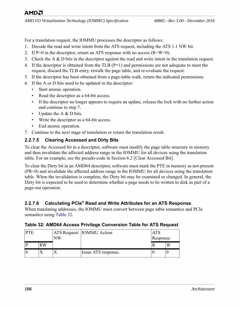
106 Architecture
48882—Rev 3.00—December 2016AMD I/O Virtualization Technology (IOMMU) Specification
For a translation request, the IOMMU processes the descriptor as follows:1. Decode the read and write intent from the ATS request, including the ATS 1.1 NW bit.2. If P=0 in the descriptor, return an ATS response with no access (R=W=0).3. Check the A & D bits in the descriptor against the read and write intent in the translation request.4. If the descriptor is obtained from the TLB (P=1) and permissions are not adequate to meet the
request, discard the TLB entry, rewalk the page table, and re-evaluate the request.5. If the descriptor has been obtained from a page-table walk, return the indicated permissions.6. If the A or D bits need to be updated in the descriptor:
• Start atomic operation.• Read the descriptor as a 64-bit access.• If the descriptor no longer appears to require an update, release the lock with no further action
and continue to step 7.• Update the A & D bits.• Write the descriptor as a 64-bit access.• End atomic operation.
7. Continue to the next stage of translation or return the translation result.2.2.7.5 Clearing Accessed and Dirty BitsTo clear the Accessed bit in a descriptor, software must modify the page table structure in memory and then invalidate the affected address range in the IOMMU for all devices using the translation table. For an example, see the pseudo-code in Section 6.2 [Clear Accessed Bit]. To clear the Dirty bit in an AMD64 descriptor, software must mark the PTE in memory as not-present (PR=0) and invalidate the affected address range in the IOMMU for all devices using the translation table. When the invalidation is complete, the Dirty bit may be examined or changed. In general, the Dirty bit is expected to be used to determine whether a page needs to be written to disk as part of a page-out operation. 2.2.7.6 Calculating PCIe® Read and Write Attributes for an ATS ResponseWhen translating addresses, the IOMMU must convert between page table semantics and PCIe semantics using Table 32.
Table 32: AMD64 Access Privilege Conversion Table for ATS RequestPTE ATS Request:
NWIOMMU Action ATS
ResponseP RW R W0 X X Issue ATS response. 0 0
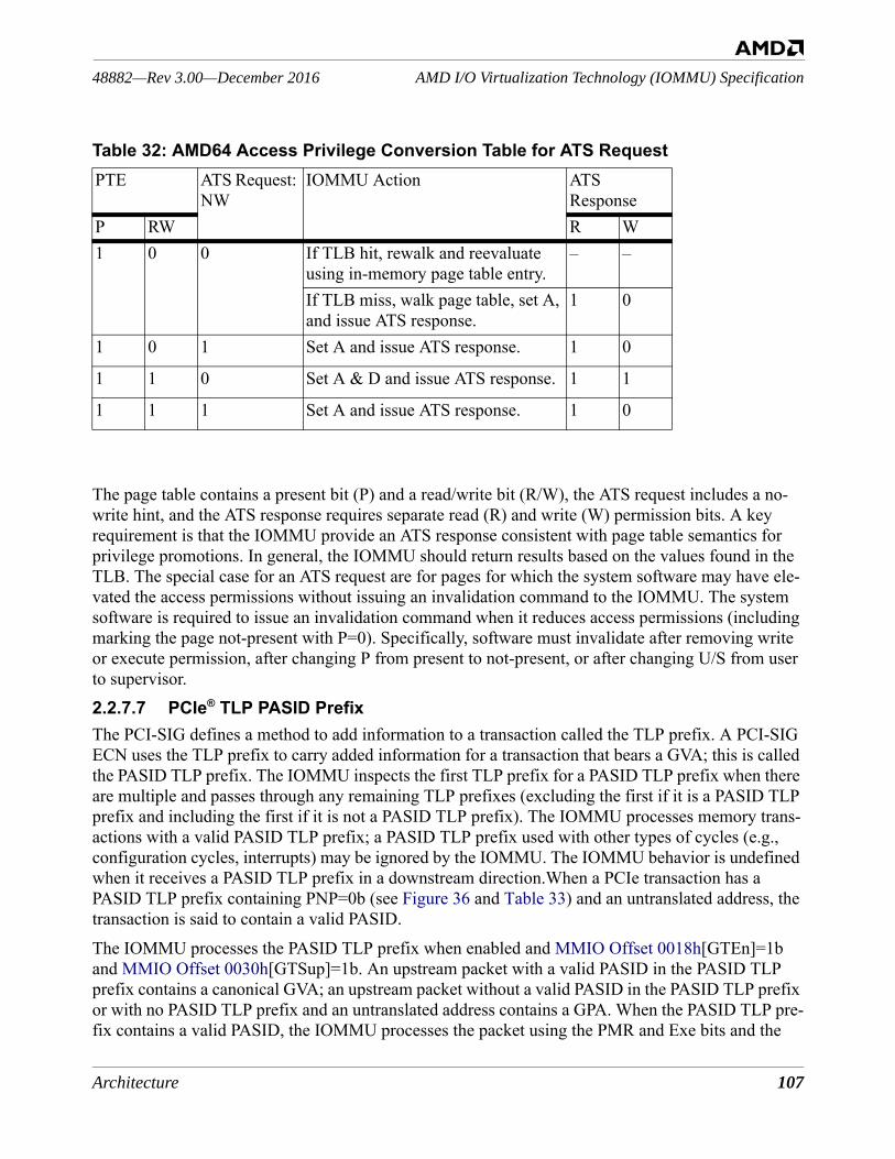
Architecture 107
AMD I/O Virtualization Technology (IOMMU) Specification48882—Rev 3.00—December 2016
The page table contains a present bit (P) and a read/write bit (R/W), the ATS request includes a no-write hint, and the ATS response requires separate read (R) and write (W) permission bits. A key requirement is that the IOMMU provide an ATS response consistent with page table semantics for privilege promotions. In general, the IOMMU should return results based on the values found in the TLB. The special case for an ATS request are for pages for which the system software may have ele-vated the access permissions without issuing an invalidation command to the IOMMU. The system software is required to issue an invalidation command when it reduces access permissions (including marking the page not-present with P=0). Specifically, software must invalidate after removing write or execute permission, after changing P from present to not-present, or after changing U/S from user to supervisor.2.2.7.7 PCIe® TLP PASID PrefixThe PCI-SIG defines a method to add information to a transaction called the TLP prefix. A PCI-SIG ECN uses the TLP prefix to carry added information for a transaction that bears a GVA; this is called the PASID TLP prefix. The IOMMU inspects the first TLP prefix for a PASID TLP prefix when there are multiple and passes through any remaining TLP prefixes (excluding the first if it is a PASID TLP prefix and including the first if it is not a PASID TLP prefix). The IOMMU processes memory trans-actions with a valid PASID TLP prefix; a PASID TLP prefix used with other types of cycles (e.g., configuration cycles, interrupts) may be ignored by the IOMMU. The IOMMU behavior is undefined when it receives a PASID TLP prefix in a downstream direction.When a PCIe transaction has a PASID TLP prefix containing PNP=0b (see Figure 36 and Table 33) and an untranslated address, the transaction is said to contain a valid PASID. The IOMMU processes the PASID TLP prefix when enabled and MMIO Offset 0018h[GTEn]=1b and MMIO Offset 0030h[GTSup]=1b. An upstream packet with a valid PASID in the PASID TLP prefix contains a canonical GVA; an upstream packet without a valid PASID in the PASID TLP prefix or with no PASID TLP prefix and an untranslated address contains a GPA. When the PASID TLP pre-fix contains a valid PASID, the IOMMU processes the packet using the PMR and Exe bits and the
1 0 0 If TLB hit, rewalk and reevaluate using in-memory page table entry.
– –
If TLB miss, walk page table, set A, and issue ATS response.
1 0
1 0 1 Set A and issue ATS response. 1 0
1 1 0 Set A & D and issue ATS response. 1 1
1 1 1 Set A and issue ATS response. 1 0
Table 32: AMD64 Access Privilege Conversion Table for ATS RequestPTE ATS Request:
NWIOMMU Action ATS
ResponseP RW R W

108 Architecture
48882—Rev 3.00—December 2016AMD I/O Virtualization Technology (IOMMU) Specification
guest translation tables. When the PASID TLP prefix does not contain a valid PASID (PNP=1b), the IOMMU ignores the PASID, PMR, and Exe fields.The PASID TLP prefix contains a 24-bit payload that is interpreted by the IOMMU in the following way, as specified by the PCI-SIG PCIe ECR for “Process Address Space Identifier Prefix”:
Figure 36: PCIe® TLP PASID Prefix Payload Format
When a PCIe transaction contains a valid PASID, the packet contains a GVA. A DeviceID value, con-sisting of BusID, Device and FunctionID values (BDF) is used to select GPA-to-SPA translation tables and the PASID TLP prefix contains Exe, PMR, PNP, and PASID information. The PASID is used to select the GVA-to-GPA translation tables. When enabled (see MMIO Offset 0030h[GTSup] and MMIO Offset 0018h[GTEn]), the IOMMU processes the PASID TLP prefix on memory-access PCIe packets, PCIe ATS packets, and PCIe PRI packets. The IOMMU does not process the PASID TLP prefix on an MSI-X or MSI interrupt packet. If an I/O device supplies a PASID TLP prefix that the IOMMU does not process, the IOMMU reports an error in the event log (see Section 2.5.9 [INVALID_DEVICE_REQUEST Event]). When a PCIe memory transaction contains no valid PASID, the packet contains a GPA and the DeviceID is used to select GPA-to-SPA translation tables.When the IOMMU receives a TLP prefix with Fmt=001b and Type=100b, it is processed as a PASID TLP prefix and the TLP prefix payload is interpreted to extract the fields in Table 33. If the TLP Pre-fix Type !=100b, the IOMMU handles the TLP prefix as defined in the PCI-SIG PCIe specifications. Although the PCI-SIG TLP specification allows for multiple TLP prefixes on a single packet, the IOMMU interprets only the first TLP prefix to determine if the transaction contains a PASID. The IOMMU behavior in response to a PASID TLP prefix other than the first prefix is not defined. 2.2.7.8 Maximum PASID value (PASmax)The maximum PASID value supported by a given IOMMU implementation can be calculated using
23 22 21 20 19 0
PMR
Exe
PNP
Resv PASID[19:0]
Table 33: PCIe® TLP Prefix Payload FieldsBits Description23 PMR: Privileged Mode Requested. 0=non-privileged (user) request. 1=privileged (super-
visor) request.22 Exe: execute requested. 0=no execute permission requested. 1=execute permission
requested. 21 PNP: PASID Not Present. 0=PASID field contains the PASID to use for the transaction.
1=PASID field is not valid.20 Reserved. Note: Although this bit is reserved, it is passed through the IOMMU as received
from the peripheral.19:0 PASID[19:0]: Guest process address space ID.
Architecture 109
AMD I/O Virtualization Technology (IOMMU) Specification48882—Rev 3.00—December 2016
the value read from the PASmax field of the EFR (see MMIO Offset 0030h[PASmax]). The maxi-mum PASID value supported is equal to (2PASmax−1). Each peripheral may support a smaller value. System software is required to program the guest CR3 tables so that PASID values out-of-range for the peripheral or for the IOMMU are marked not-valid (see Table 20 and Table 25).2.2.7.9 Calculating Non-Snoop Accesses Attribute for an ATS ResponseIn an ATS response, the N field controls whether a device may set the NoSnoop attribute in a DMA response based upon the returned translation. If N=1, the device may only generate DMA with NoSnoop=0. If N=0, the device may use proprietary means to determine how to set NoSnoop.For ATS responses containing only host translations, the DTE[FC] attribute is used to control the N field. For ATS responses containing guest translations, if IOMMU Offset 0030h[AttrFWSup]=0, the N field is always set to 1. If IOMMU Offset 0030h[AttrFWSup]=1, the value of the N field is determined by the values of DTE[AttrV], DTE[SnoopAttribute] and DTE[Mode0FC]. See Section 2.2.2.1 Device Table Entry.2.2.7.10 Extended Coherency AttributesIf MMIO Offset 0030h[AttrFWSup] = 1, the IOMMU supports returning additional coherency infor-mation beyond the N field in response to an ATS request. The nature of the coherency information, the mechanisms used to communicate this information and the methods to determine whether an I/O device support receiving this information are outside the scope of this specification.
2.2.8 Guest Virtual APIC Table for Interrupt VirtualizationIf the Guest Virtual APIC feature is supported, the IOMMU provides the Guest Virtual APIC Table which is used to virtualize interrupts. When enabled, the IOMMU can cause interrupts to be delivered directly to running guests without hypervisor intervention for a device. When interrupt remapping and interrupt virtualization are both enabled, an incoming device interrupt is first virtualized using the IRTE and then delivered using the AMD virtual interrupt controller. Interrupt virtualization requires compatible support in the IOMMU and the processor. When MMIO Offset 0030h[GASup]=0, the IOMMU does not support interrupt virtualization using the Guest Virtual APIC Table.When MMIO Offset 0030h[GASup]=1, device interrupt virtualization is enabled for the IOMMU by programming MMIO Offset 0018h[GAEn]=1, IRTE[GuestMode]=1 to activate interrupt virtualiza-tion for the device interrupt, and the Guest Virtual APIC Table Root Pointer in the IRTE to the base address (SPA) of the guest virtual APIC backing page. Further information can be found in Chapter 15 of APM2 (Advanced Virtual Interrupt Controller).
2.2.9 Guest I/O ProtectionIf the IOMMU supports Guest I/O Protection (see MMIO Offset 0030h[GIoSup]), I/O devices that do not support PASID may be used in conjunction with guest address translation. This feature enabled by setting DTE[GIoV]. When enabled, a default PASID of 0 is applied to all non-PASID DMA requests from the enabled peripheral. All features related to guest and nested translation are then applied. Received DMA requests without PASID in the 0xFEEx_xxxx address range are treated as
110 Architecture
48882—Rev 3.00—December 2016AMD I/O Virtualization Technology (IOMMU) Specification
MSI interrupts and are processed using interrupt remapping rather than address translation.Operating systems are encouraged to use this feature to construct I/O protection buffers using the guest page table format.IOMMU hardware that supports the Guest I/O Protection feature is capable of walking the nested page tables formed when the OS is virtualized by a Hypervisor. This is not possible if the OS uses the host page table format for I/O protection.
2.3 Starting the IOMMUBefore attempting to access memory-mapped registers, software must allocate a contiguous physical memory range for the registers and program the base address using IOMMU Base Address Low Reg-ister [Capability Offset 04h] and IOMMU Base Address High Register [Capability Offset 08h]. If MMIO Offset 0030h[PCSup] = 0, 16 Kbytes of space must be allocated. If MMIO Offset 0030h[PCSup] = 1, 512 Kbytes of space must be allocated.
2.3.1 Data Structure InitializationTo start the IOMMU and activate table walking, etc., use the following procedure after a system reset.• System firmware must program any implementation-defined registers to prepare for software use
of the guest virtual APIC.• If not previously set, initialize the SMI filter registers (see Section 2.1.5 [System Management
Interrupt (SMI) Controls]).• If not previously set, initialize the following registers:
• the Device Table Base Address Register [MMIO Offset 0000h],• the Command Buffer Base Address Register [MMIO Offset 0008h],• the Command Buffer Head Pointer Register [MMIO Offset 2000h],• the Command Buffer Tail Pointer Register [MMIO Offset 2008h],• the IOMMU Exclusion Base Register [MMIO Offset 0020h] and the IOMMU Exclusion
Range Limit Register [MMIO Offset 0028h], if used,• the Event Log Base Address Register [MMIO Offset 0010h], the Event Log Head Pointer
Register [MMIO Offset 2010h] and the Event Log Tail Pointer Register [MMIO Offset 2018h], if used.
• Write the IOMMU Control Register [MMIO Offset 0018h] with EventLogEn=1b (if used), CmdBufEn=1b, and IommuEn=1b. Other IOMMU Control Register [MMIO Offset 0018h] bits should be set as necessary.
• If using peripheral page requests, software must initialize the PPR Log registers in addition to the other registers before setting IommuEn=1b:• PPR Log Base Address Register [MMIO Offset 0038h],• IOMMU PPR Log Head Pointer Register [MMIO Offset 2030h], and• IOMMU PPR Log Tail Pointer Register [MMIO Offset 2038h].
• Software must write the IOMMU Control Register [MMIO Offset 0018h] with PPREn = 1b, PPRLogEn = 1b; and, if using interrupts, PprIntEn = 1b.
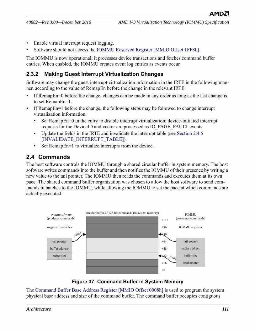
Architecture 111
AMD I/O Virtualization Technology (IOMMU) Specification48882—Rev 3.00—December 2016
• Enable virtual interrupt request logging.• Software should not access the IOMMU Reserved Register [MMIO Offset 1FF8h].The IOMMU is now operational; it processes device transactions and fetches command buffer entries. When enabled, the IOMMU creates event log entries as events occur.
2.3.2 Making Guest Interrupt Virtualization ChangesSoftware may change the guest interrupt virtualization information in the IRTE in the following man-ner, according to the value of RemapEn before the change in the relevant IRTE. • If RemapEn=0 before the change, changes can be made in any order as long as the last change is
to set RemapEn=1.• If RemapEn=1 before the change, the following steps may be followed to change interrupt
virtualization information:• Set RemapEn=0 in the entry to disable interrupt virtualization; device-initiated interrupt
requests for the DeviceID and vector are processed as IO_PAGE_FAULT events.• Update the fields in the IRTE and invalidate the interrupt table (see Section 2.4.5
[INVALIDATE_INTERRUPT_TABLE]).• Set RemapEn=1 to virtualize interrupts from the device.
2.4 CommandsThe host software controls the IOMMU through a shared circular buffer in system memory. The host software writes commands into the buffer and then notifies the IOMMU of their presence by writing a new value to the tail pointer. The IOMMU then reads the commands and executes them at its own pace. The shared command buffer organization was chosen to allow the host software to send com-mands in batches to the IOMMU, while allowing the IOMMU to set the pace at which commands are actually executed.
Figure 37: Command Buffer in System MemoryThe Command Buffer Base Address Register [MMIO Offset 0008h] is used to program the system physical base address and size of the command buffer. The command buffer occupies contiguous
circular buffer of 128-bit commands (in system memory)
+112
+96
+80
+64
+48
+32
+16
+0
IOMMU(consumes commands)
system software(produces commands)
tail pointer
writes
head pointer
IOMMU registerssuggested variables
buffer address
buffer size
buffer address
buffer size reads
tail pointer
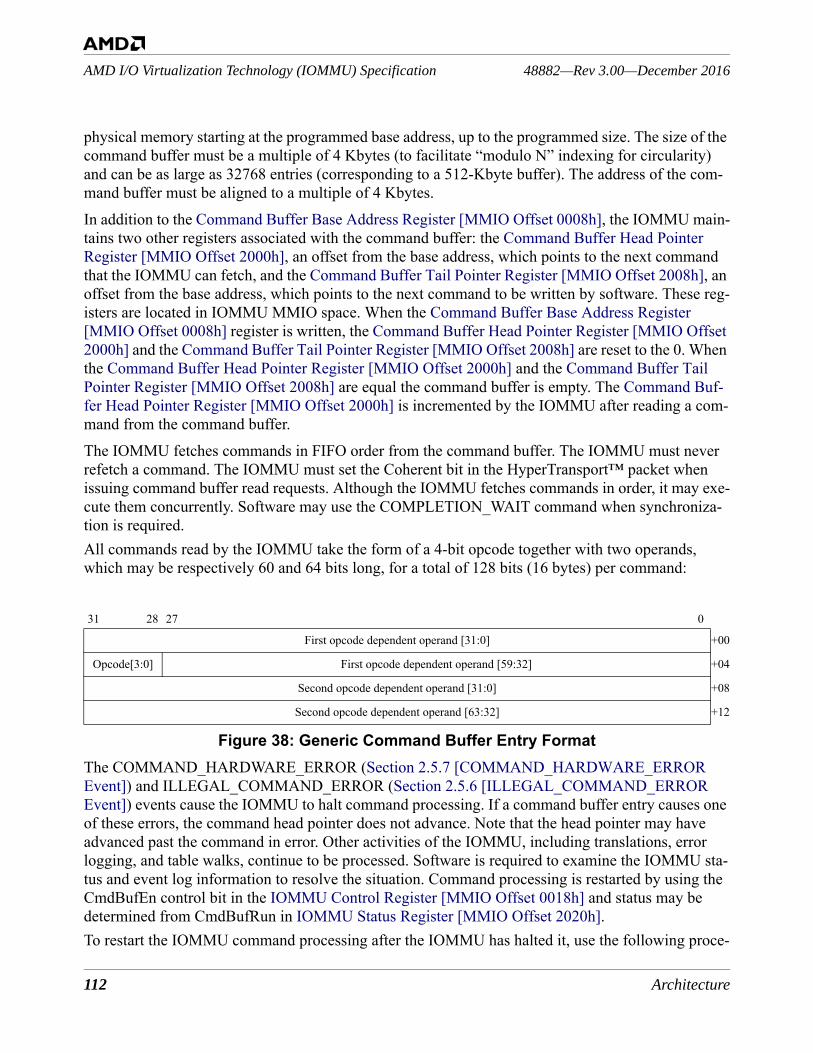
112 Architecture
48882—Rev 3.00—December 2016AMD I/O Virtualization Technology (IOMMU) Specification
physical memory starting at the programmed base address, up to the programmed size. The size of the command buffer must be a multiple of 4 Kbytes (to facilitate “modulo N” indexing for circularity) and can be as large as 32768 entries (corresponding to a 512-Kbyte buffer). The address of the com-mand buffer must be aligned to a multiple of 4 Kbytes.In addition to the Command Buffer Base Address Register [MMIO Offset 0008h], the IOMMU main-tains two other registers associated with the command buffer: the Command Buffer Head Pointer Register [MMIO Offset 2000h], an offset from the base address, which points to the next command that the IOMMU can fetch, and the Command Buffer Tail Pointer Register [MMIO Offset 2008h], an offset from the base address, which points to the next command to be written by software. These reg-isters are located in IOMMU MMIO space. When the Command Buffer Base Address Register [MMIO Offset 0008h] register is written, the Command Buffer Head Pointer Register [MMIO Offset 2000h] and the Command Buffer Tail Pointer Register [MMIO Offset 2008h] are reset to the 0. When the Command Buffer Head Pointer Register [MMIO Offset 2000h] and the Command Buffer Tail Pointer Register [MMIO Offset 2008h] are equal the command buffer is empty. The Command Buf-fer Head Pointer Register [MMIO Offset 2000h] is incremented by the IOMMU after reading a com-mand from the command buffer.The IOMMU fetches commands in FIFO order from the command buffer. The IOMMU must never refetch a command. The IOMMU must set the Coherent bit in the HyperTransport™ packet when issuing command buffer read requests. Although the IOMMU fetches commands in order, it may exe-cute them concurrently. Software may use the COMPLETION_WAIT command when synchroniza-tion is required.All commands read by the IOMMU take the form of a 4-bit opcode together with two operands, which may be respectively 60 and 64 bits long, for a total of 128 bits (16 bytes) per command:
Figure 38: Generic Command Buffer Entry FormatThe COMMAND_HARDWARE_ERROR (Section 2.5.7 [COMMAND_HARDWARE_ERROR Event]) and ILLEGAL_COMMAND_ERROR (Section 2.5.6 [ILLEGAL_COMMAND_ERROR Event]) events cause the IOMMU to halt command processing. If a command buffer entry causes one of these errors, the command head pointer does not advance. Note that the head pointer may have advanced past the command in error. Other activities of the IOMMU, including translations, error logging, and table walks, continue to be processed. Software is required to examine the IOMMU sta-tus and event log information to resolve the situation. Command processing is restarted by using the CmdBufEn control bit in the IOMMU Control Register [MMIO Offset 0018h] and status may be determined from CmdBufRun in IOMMU Status Register [MMIO Offset 2020h].To restart the IOMMU command processing after the IOMMU has halted it, use the following proce-
31 28 27 0
First opcode dependent operand [31:0] +00
Opcode[3:0] First opcode dependent operand [59:32] +04
Second opcode dependent operand [31:0] +08
Second opcode dependent operand [63:32] +12
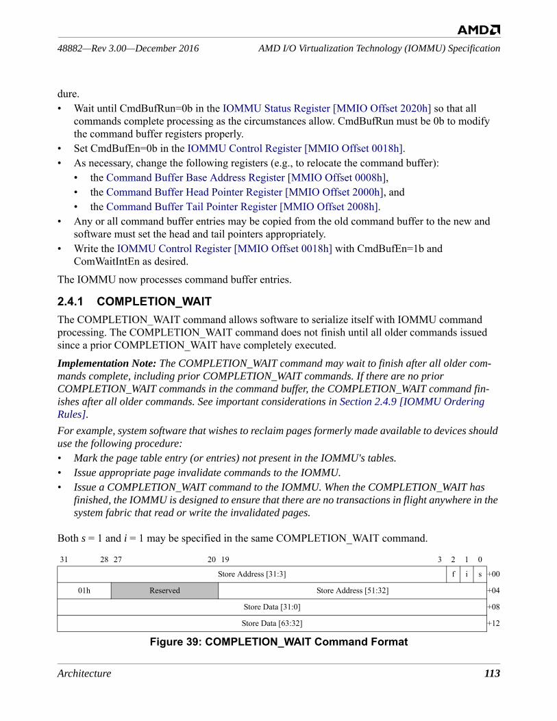
Architecture 113
AMD I/O Virtualization Technology (IOMMU) Specification48882—Rev 3.00—December 2016
dure.• Wait until CmdBufRun=0b in the IOMMU Status Register [MMIO Offset 2020h] so that all
commands complete processing as the circumstances allow. CmdBufRun must be 0b to modify the command buffer registers properly.
• Set CmdBufEn=0b in the IOMMU Control Register [MMIO Offset 0018h].• As necessary, change the following registers (e.g., to relocate the command buffer):
• the Command Buffer Base Address Register [MMIO Offset 0008h],• the Command Buffer Head Pointer Register [MMIO Offset 2000h], and • the Command Buffer Tail Pointer Register [MMIO Offset 2008h].
• Any or all command buffer entries may be copied from the old command buffer to the new and software must set the head and tail pointers appropriately.
• Write the IOMMU Control Register [MMIO Offset 0018h] with CmdBufEn=1b and ComWaitIntEn as desired.
The IOMMU now processes command buffer entries.
2.4.1 COMPLETION_WAITThe COMPLETION_WAIT command allows software to serialize itself with IOMMU command processing. The COMPLETION_WAIT command does not finish until all older commands issued since a prior COMPLETION_WAIT have completely executed.Implementation Note: The COMPLETION_WAIT command may wait to finish after all older com-mands complete, including prior COMPLETION_WAIT commands. If there are no prior COMPLETION_WAIT commands in the command buffer, the COMPLETION_WAIT command fin-ishes after all older commands. See important considerations in Section 2.4.9 [IOMMU Ordering Rules].For example, system software that wishes to reclaim pages formerly made available to devices should use the following procedure:• Mark the page table entry (or entries) not present in the IOMMU's tables.• Issue appropriate page invalidate commands to the IOMMU.• Issue a COMPLETION_WAIT command to the IOMMU. When the COMPLETION_WAIT has
finished, the IOMMU is designed to ensure that there are no transactions in flight anywhere in the system fabric that read or write the invalidated pages.
Both s = 1 and i = 1 may be specified in the same COMPLETION_WAIT command.
Figure 39: COMPLETION_WAIT Command Format
31 28 27 20 19 3 2 1 0
Store Address [31:3] f i s +00
01h Reserved Store Address [51:32] +04
Store Data [31:0] +08
Store Data [63:32] +12
114 Architecture
48882—Rev 3.00—December 2016AMD I/O Virtualization Technology (IOMMU) Specification
2.4.2 INVALIDATE_DEVTAB_ENTRYWhen system software changes a Device Table entry, it must instruct the IOMMU to invalidate that DeviceID from its internal caches. The IOMMU is then forced to reload the Device Table entry before DMA from the device is allowed. The IOMMU may reload the Device Table entry any time after the invalidation has completed.When software invalidates a DeviceID corresponding to an IOMMU-aware device with its own IOTLB, it should immediately follow INVALIDATE_DEVTAB_ENTRY with an INVALIDATE_IOTLB_PAGES targeted at the same DeviceID and sized to invalidate the full 64-bit address space for the given DeviceID. For a multi-function device this only invalidates the IOTLB entries for the specified function.
Table 34: COMPLETION_WAIT FieldsBits Description31:3+00
Store Address[31:3]. The lower portion of the SPA into which the IOMMU may store the Store Data.
2+00
f: flush queue. 0=execution of younger commands may begin at any time. 1=the IOMMU does not begin execution of any younger commands until COMPLETION_WAIT has fin-ished.
1+00
i: completion interrupt. 0=the IOMMU does not set MMIO Offset 2020h[ComWaitInt]. 1=the IOMMU sets MMIO Offset 2020h[ComWaitInt]. See Capability Offset 10h[Msi-Num].
0+00
s: completion store. 0=the IOMMU does not write the Store Data value to the Store Address. 1=the IOMMU writes the specified 64-bit Store Data value to the Store Address. Software can use this write to update a semaphore indicating to the waiting process that it can continue execution. The address written by the COMPLETION_WAIT must be located in system memory.Implementation Note: The write operation must be coherent and not in the isochronous channel. Hardware must not set the PassPw bit when performing this write.
31:28+04
01h. COMPLETION_WAIT command number.
27:20+04
Reserved.
19:0+04
Store Address[51:32]. The lower portion of the SPA into which the IOMMU may store the Store Data.
31:0+08
Store Data[31:0]. The lower portion of the Store Data.
31:0+12
Store Data[63:32]. The upper portion of the Store Data.
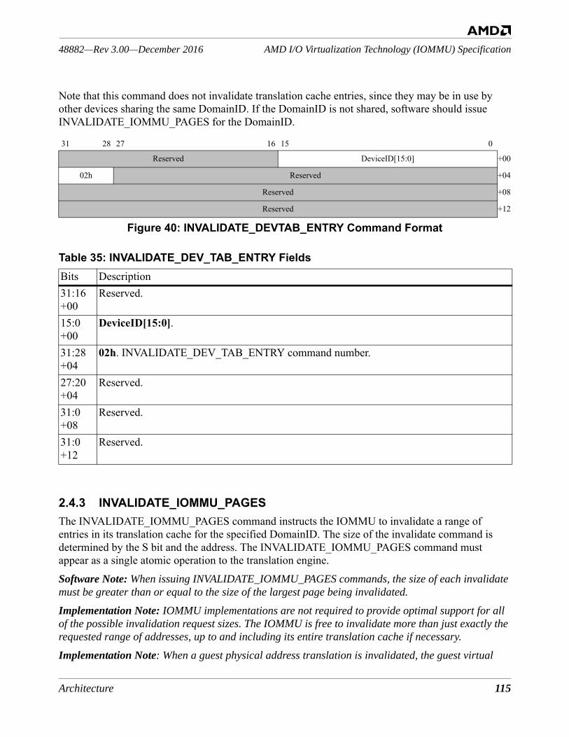
Architecture 115
AMD I/O Virtualization Technology (IOMMU) Specification48882—Rev 3.00—December 2016
Note that this command does not invalidate translation cache entries, since they may be in use by other devices sharing the same DomainID. If the DomainID is not shared, software should issue INVALIDATE_IOMMU_PAGES for the DomainID.
Figure 40: INVALIDATE_DEVTAB_ENTRY Command Format
2.4.3 INVALIDATE_IOMMU_PAGESThe INVALIDATE_IOMMU_PAGES command instructs the IOMMU to invalidate a range of entries in its translation cache for the specified DomainID. The size of the invalidate command is determined by the S bit and the address. The INVALIDATE_IOMMU_PAGES command must appear as a single atomic operation to the translation engine. Software Note: When issuing INVALIDATE_IOMMU_PAGES commands, the size of each invalidate must be greater than or equal to the size of the largest page being invalidated.
Implementation Note: IOMMU implementations are not required to provide optimal support for all of the possible invalidation request sizes. The IOMMU is free to invalidate more than just exactly the requested range of addresses, up to and including its entire translation cache if necessary.
Implementation Note: When a guest physical address translation is invalidated, the guest virtual
31 28 27 16 15 0
Reserved DeviceID[15:0] +00
02h Reserved +04
Reserved +08
Reserved +12
Table 35: INVALIDATE_DEV_TAB_ENTRY FieldsBits Description31:16+00
Reserved.
15:0+00
DeviceID[15:0].
31:28+04
02h. INVALIDATE_DEV_TAB_ENTRY command number.
27:20+04
Reserved.
31:0+08
Reserved.
31:0+12
Reserved.
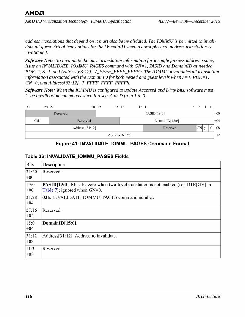
116 Architecture
48882—Rev 3.00—December 2016AMD I/O Virtualization Technology (IOMMU) Specification
address translations that depend on it must also be invalidated. The IOMMU is permitted to invali-date all guest virtual translations for the DomainID when a guest physical address translation is invalidated.
Software Note: To invalidate the guest translation information for a single process address space, issue an INVALIDATE_IOMMU_PAGES command with GN=1, PASID and DomainID as needed, PDE=1, S=1, and Address[63:12]=7_FFFF_FFFF_FFFFh. The IOMMU invalidates all translation information associated with the DomainID for both nested and guest levels when S=1, PDE=1, GN=0, and Address[63:12]=7_FFFF_FFFF_FFFFh.Software Note: When the IOMMU is configured to update Accessed and Dirty bits, software must issue invalidation commands when it resets A or D from 1 to 0.
Figure 41: INVALIDATE_IOMMU_PAGES Command Format
31 28 27 20 19 16 15 12 11 3 2 1 0
Reserved PASID[19:0] +00
03h Reserved DomainID[15:0] +04
Address [31:12] Reserved GN PDE S +08
Address [63:32] +12
Table 36: INVALIDATE_IOMMU_PAGES FieldsBits Description31:20+00
Reserved.
19:0+00
PASID[19:0]. Must be zero when two-level translation is not enabled (see DTE[GV] in Table 7); ignored when GN=0.
31:28+04
03h. INVALIDATE_IOMMU_PAGES command number.
27:16+04
Reserved.
15:0+04
DomainID[15:0].
31:12+08
Address[31:12]. Address to invalidate.
11:3+08
Reserved.
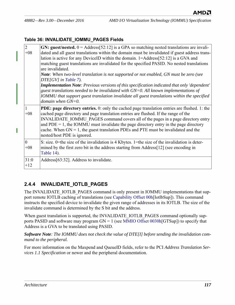
Architecture 117
AMD I/O Virtualization Technology (IOMMU) Specification48882—Rev 3.00—December 2016
2.4.4 INVALIDATE_IOTLB_PAGESThe INVALIDATE_IOTLB_PAGES command is only present in IOMMU implementations that sup-port remote IOTLB caching of translations (see Capability Offset 00h[IotlbSup]). This command instructs the specified device to invalidate the given range of addresses in its IOTLB. The size of the invalidate command is determined by the S bit and the address. When guest translation is supported, the INVALIDATE_IOTLB_PAGES command optionally sup-ports PASID and software may program GN = 1 (see MMIO Offset 0030h[GTSup]) to specify that Address is a GVA to be translated using PASID.Software Note: The IOMMU does not check the value of DTE[I] before sending the invalidation com-mand to the peripheral.
For more information on the Maxpend and QueueID fields, refer to the PCI Address Translation Ser-vices 1.1 Specification or newer and the peripheral documentation.
2+08
GN: guest/nested. 0 = Address[52:12] is a GPA so matching nested translations are invali-dated and all guest translations within the domain must be invalidated if guest address trans-lation is active for any DeviceID within the domain. 1=Address[52:12] is a GVA and matching guest translations are invalidated for the specified PASID. No nested translations are invalidated. Note: When two-level translation is not supported or not enabled, GN must be zero (see DTE[GV] in Table 7).Implementation Note: Previous versions of this specification indicated that only 'dependent' guest translations needed to be invalidated with GN=0. All known implementations of IOMMU that support guest translation invalidate all guest translations within the specified domain when GN=0.
1+08
PDE: page directory entries. 0: only the cached page translation entries are flushed. 1: the cached page directory and page translation entries are flushed. If the range of the INVALIDATE_IOMMU_PAGES command covers all of the pages in a page directory entry and PDE = 1, the IOMMU must invalidate the page directory entry in the page directory cache. When GN = 1, the guest translation PDEs and PTE must be invalidated and the nested/host PDE is ignored.
0+08
S: size. 0=the size of the invalidation is 4 Kbytes. 1=the size of the invalidation is deter-mined by the first zero bit in the address starting from Address[12] (see encoding in Table 14).
31:0+12
Address[63:32]. Address to invalidate.
Table 36: INVALIDATE_IOMMU_PAGES Fields
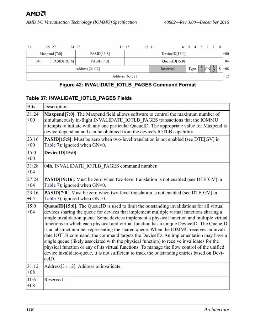
118 Architecture
48882—Rev 3.00—December 2016AMD I/O Virtualization Technology (IOMMU) Specification
Figure 42: INVALIDATE_IOTLB_PAGES Command Format
31 28 27 24 23 16 15 12 11 6 5 4 3 2 1 0
Maxpend [7:0] PASID[15:8] DeviceID[15:0] +00
04h PASID[19:16] PASID[7:0] QueueID[15:0] +04
Address [31:12] Reserved Type
Resv GN
Resv S +08
Address [63:32] +12
Table 37: INVALIDATE_IOTLB_PAGES FieldsBits Description31:24+00
Maxpend[7:0]. The Maxpend field allows software to control the maximum number of simultaneously in-flight INVALIDATE_IOTLB_PAGES transactions that the IOMMU attempts to initiate with any one particular QueueID. The appropriate value for Maxpend is device-dependent and can be obtained from the device's IOTLB capability.
23:16+00
PASID[15:8]. Must be zero when two-level translation is not enabled (see DTE[GV] in Table 7); ignored when GN=0.
15:0+00
DeviceID[15:0].
31:28+04
04h. INVALIDATE_IOTLB_PAGES command number.
27:24+04
PASID[19:16]. Must be zero when two-level translation is not enabled (see DTE[GV] in Table 7); ignored when GN=0.
23:16+04
PASID[7:0]. Must be zero when two-level translation is not enabled (see DTE[GV] in Table 7); ignored when GN=0.
15:0+04
QueueID[15:0]. The QueueID is used to limit the outstanding invalidations for all virtual devices sharing the queue for devices that implement multiple virtual functions sharing a single invalidation queue. Some devices implement a physical function and multiple virtual functions in which each physical and virtual function has a unique DeviceID. The QueueID is an abstract number representing the shared queue. When the IOMMU receives an invali-date IOTLB command, the command targets the DeviceID. An implementation may have a single queue (likely associated with the physical function) to receive invalidates for the physical function or any of its virtual functions. To manage the flow control of the unified device invalidate-queue, it is not sufficient to track the outstanding entries based on Devi-ceID.
31:12+08
Address[31:12]. Address to invalidate.
11:6+08
Reserved.
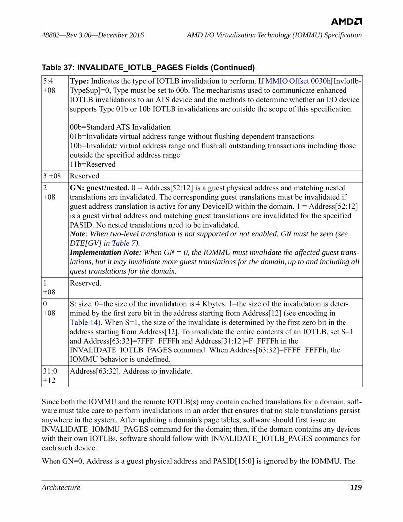
Architecture 119
AMD I/O Virtualization Technology (IOMMU) Specification48882—Rev 3.00—December 2016
Since both the IOMMU and the remote IOTLB(s) may contain cached translations for a domain, soft-ware must take care to perform invalidations in an order that ensures that no stale translations persist anywhere in the system. After updating a domain's page tables, software should first issue an INVALIDATE_IOMMU_PAGES command for the domain; then, if the domain contains any devices with their own IOTLBs, software should follow with INVALIDATE_IOTLB_PAGES commands for each such device.When GN=0, Address is a guest physical address and PASID[15:0] is ignored by the IOMMU. The
5:4+08
Type: Indicates the type of IOTLB invalidation to perform. If MMIO Offset 0030h[InvIotlb-TypeSup]=0, Type must be set to 00b. The mechanisms used to communicate enhanced IOTLB invalidations to an ATS device and the methods to determine whether an I/O device supports Type 01b or 10b IOTLB invalidations are outside the scope of this specification.
00b=Standard ATS Invalidation01b=Invalidate virtual address range without flushing dependent transactions 10b=Invalidate virtual address range and flush all outstanding transactions including those outside the specified address range11b=Reserved
3 +08 Reserved2+08
GN: guest/nested. 0 = Address[52:12] is a guest physical address and matching nested translations are invalidated. The corresponding guest translations must be invalidated if guest address translation is active for any DeviceID within the domain. 1 = Address[52:12] is a guest virtual address and matching guest translations are invalidated for the specified PASID. No nested translations need to be invalidated. Note: When two-level translation is not supported or not enabled, GN must be zero (see DTE[GV] in Table 7).Implementation Note: When GN = 0, the IOMMU must invalidate the affected guest trans-lations, but it may invalidate more guest translations for the domain, up to and including all guest translations for the domain.
1+08
Reserved.
0+08
S: size. 0=the size of the invalidation is 4 Kbytes. 1=the size of the invalidation is deter-mined by the first zero bit in the address starting from Address[12] (see encoding in Table 14). When S=1, the size of the invalidate is determined by the first zero bit in the address starting from Address[12]. To invalidate the entire contents of an IOTLB, set S=1 and Address[63:32]=7FFF_FFFFh and Address[31:12]=F_FFFFh in the INVALIDATE_IOTLB_PAGES command. When Address[63:32]=FFFF_FFFFh, the IOMMU behavior is undefined.
31:0+12
Address[63:32]. Address to invalidate.
Table 37: INVALIDATE_IOTLB_PAGES Fields (Continued)
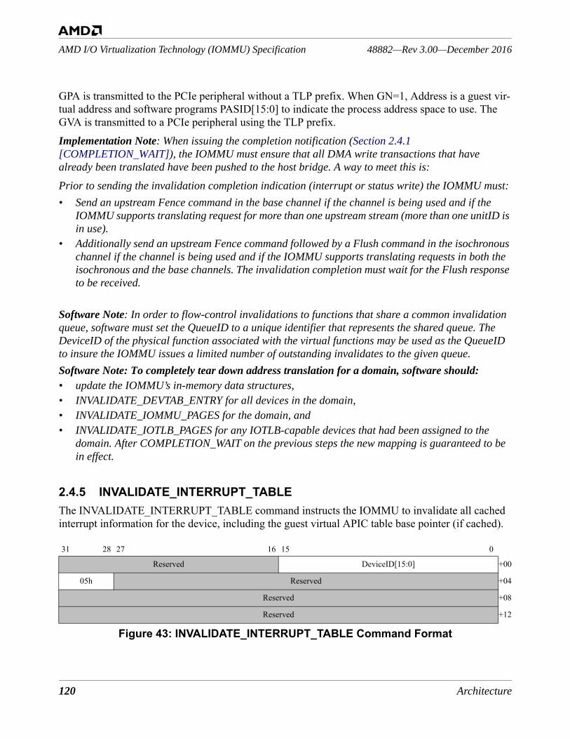
120 Architecture
48882—Rev 3.00—December 2016AMD I/O Virtualization Technology (IOMMU) Specification
GPA is transmitted to the PCIe peripheral without a TLP prefix. When GN=1, Address is a guest vir-tual address and software programs PASID[15:0] to indicate the process address space to use. The GVA is transmitted to a PCIe peripheral using the TLP prefix.Implementation Note: When issuing the completion notification (Section 2.4.1 [COMPLETION_WAIT]), the IOMMU must ensure that all DMA write transactions that have already been translated have been pushed to the host bridge. A way to meet this is:
Prior to sending the invalidation completion indication (interrupt or status write) the IOMMU must:• Send an upstream Fence command in the base channel if the channel is being used and if the
IOMMU supports translating request for more than one upstream stream (more than one unitID is in use).
• Additionally send an upstream Fence command followed by a Flush command in the isochronous channel if the channel is being used and if the IOMMU supports translating requests in both the isochronous and the base channels. The invalidation completion must wait for the Flush response to be received.
Software Note: In order to flow-control invalidations to functions that share a common invalidation queue, software must set the QueueID to a unique identifier that represents the shared queue. The DeviceID of the physical function associated with the virtual functions may be used as the QueueID to insure the IOMMU issues a limited number of outstanding invalidates to the given queue.Software Note: To completely tear down address translation for a domain, software should: • update the IOMMU’s in-memory data structures,• INVALIDATE_DEVTAB_ENTRY for all devices in the domain,• INVALIDATE_IOMMU_PAGES for the domain, and• INVALIDATE_IOTLB_PAGES for any IOTLB-capable devices that had been assigned to the
domain. After COMPLETION_WAIT on the previous steps the new mapping is guaranteed to be in effect.
2.4.5 INVALIDATE_INTERRUPT_TABLEThe INVALIDATE_INTERRUPT_TABLE command instructs the IOMMU to invalidate all cached interrupt information for the device, including the guest virtual APIC table base pointer (if cached).
Figure 43: INVALIDATE_INTERRUPT_TABLE Command Format
31 28 27 16 15 0
Reserved DeviceID[15:0] +00
05h Reserved +04
Reserved +08
Reserved +12
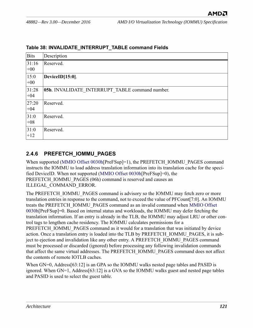
Architecture 121
AMD I/O Virtualization Technology (IOMMU) Specification48882—Rev 3.00—December 2016
2.4.6 PREFETCH_IOMMU_PAGESWhen supported (MMIO Offset 0030h[PreFSup]=1), the PREFETCH_IOMMU_PAGES command instructs the IOMMU to load address translation information into its translation cache for the speci-fied DeviceID. When not supported (MMIO Offset 0030h[PreFSup]=0), the PREFETCH_IOMMU_PAGES (06h) command is reserved and causes an ILLEGAL_COMMAND_ERROR. The PREFETCH_IOMMU_PAGES command is advisory so the IOMMU may fetch zero or more translation entries in response to the command, not to exceed the value of PFCount[7:0]. An IOMMU treats the PREFETCH_IOMMU_PAGES command as an invalid command when MMIO Offset 0030h[PreFSup]=0. Based on internal status and workloads, the IOMMU may defer fetching the translation information. If an entry is already in the TLB, the IOMMU may adjust LRU or other con-trol tags to lengthen cache residency. The IOMMU calculates permissions for a PREFETCH_IOMMU_PAGES command as it would for a translation that was initiated by device action. Once a translation entry is loaded into the TLB by PREFETCH_IOMMU_PAGES, it is sub-ject to ejection and invalidation like any other entry. A PREFETCH_IOMMU_PAGES command must be processed or discarded (ignored) before processing any following invalidation commands that affect the same virtual addresses. The PREFETCH_IOMMU_PAGES command does not affect the contents of remote IOTLB caches.When GN=0, Address[63:12] is an GPA so the IOMMU walks nested page tables and PASID is ignored. When GN=1, Address[63:12] is a GVA so the IOMMU walks guest and nested page tables and PASID is used to select the guest table.
Table 38: INVALIDATE_INTERRUPT_TABLE command FieldsBits Description31:16+00
Reserved.
15:0+00
DeviceID[15:0].
31:28+04
05h. INVALIDATE_INTERRUPT_TABLE command number.
27:20+04
Reserved.
31:0+08
Reserved.
31:0+12
Reserved.
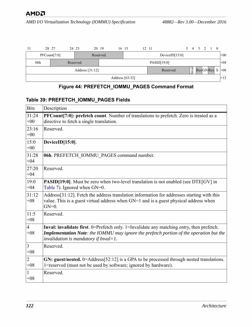
122 Architecture
48882—Rev 3.00—December 2016AMD I/O Virtualization Technology (IOMMU) Specification
Figure 44: PREFETCH_IOMMU_PAGES Command Format
31 28 27 24 23 20 19 16 15 12 11 5 4 3 2 1 0
PFCount[7:0] Reserved DeviceID[15:0] +00
06h Reserved PASID[19:0] +04
Address [31:12] Reserved
Inva
l
Res GN Res S +08
Address [63:32] +12
Table 39: PREFETCH_IOMMU_PAGES FieldsBits Description31:24+00
PFCount[7:0]: prefetch count. Number of translations to prefetch. Zero is treated as a directive to fetch a single translation.
23:16+00
Reserved.
15:0+00
DeviceID[15:0].
31:28+04
06h. PREFETCH_IOMMU_PAGES command number.
27:20+04
Reserved.
19:0+04
PASID[19:0]. Must be zero when two-level translation is not enabled (see DTE[GV] in Table 7). Ignored when GN=0.
31:12+08
Address[31:12]. Fetch the address translation information for addresses starting with this value. This is a guest virtual address when GN=1 and is a guest physical address when GN=0.
11:5+08
Reserved.
4+08
Inval: invalidate first. 0=Prefetch only. 1=Invalidate any matching entry, then prefetch. Implementation Note: the IOMMU may ignore the prefetch portion of the operation but the invalidation is mandatory if Inval=1.
3+08
Reserved.
2+08
GN: guest/nested. 0=Address[52:12] is a GPA to be processed through nested translations. 1=reserved (must not be used by software; ignored by hardware).
1+08
Reserved.
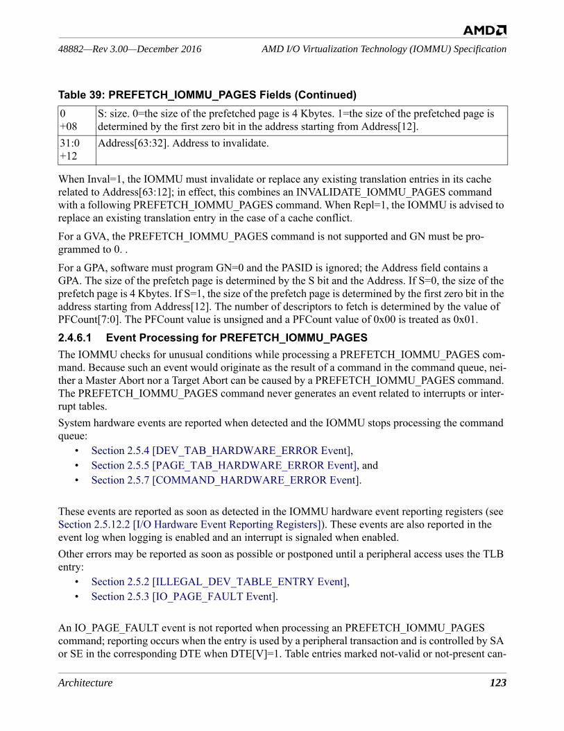
Architecture 123
AMD I/O Virtualization Technology (IOMMU) Specification48882—Rev 3.00—December 2016
When Inval=1, the IOMMU must invalidate or replace any existing translation entries in its cache related to Address[63:12]; in effect, this combines an INVALIDATE_IOMMU_PAGES command with a following PREFETCH_IOMMU_PAGES command. When Repl=1, the IOMMU is advised to replace an existing translation entry in the case of a cache conflict. For a GVA, the PREFETCH_IOMMU_PAGES command is not supported and GN must be pro-grammed to 0. .For a GPA, software must program GN=0 and the PASID is ignored; the Address field contains a GPA. The size of the prefetch page is determined by the S bit and the Address. If S=0, the size of the prefetch page is 4 Kbytes. If S=1, the size of the prefetch page is determined by the first zero bit in the address starting from Address[12]. The number of descriptors to fetch is determined by the value of PFCount[7:0]. The PFCount value is unsigned and a PFCount value of 0x00 is treated as 0x01.2.4.6.1 Event Processing for PREFETCH_IOMMU_PAGESThe IOMMU checks for unusual conditions while processing a PREFETCH_IOMMU_PAGES com-mand. Because such an event would originate as the result of a command in the command queue, nei-ther a Master Abort nor a Target Abort can be caused by a PREFETCH_IOMMU_PAGES command. The PREFETCH_IOMMU_PAGES command never generates an event related to interrupts or inter-rupt tables.System hardware events are reported when detected and the IOMMU stops processing the command queue:
• Section 2.5.4 [DEV_TAB_HARDWARE_ERROR Event],• Section 2.5.5 [PAGE_TAB_HARDWARE_ERROR Event], and• Section 2.5.7 [COMMAND_HARDWARE_ERROR Event].
These events are reported as soon as detected in the IOMMU hardware event reporting registers (see Section 2.5.12.2 [I/O Hardware Event Reporting Registers]). These events are also reported in the event log when logging is enabled and an interrupt is signaled when enabled.Other errors may be reported as soon as possible or postponed until a peripheral access uses the TLB entry:
• Section 2.5.2 [ILLEGAL_DEV_TABLE_ENTRY Event], • Section 2.5.3 [IO_PAGE_FAULT Event].
An IO_PAGE_FAULT event is not reported when processing an PREFETCH_IOMMU_PAGES command; reporting occurs when the entry is used by a peripheral transaction and is controlled by SA or SE in the corresponding DTE when DTE[V]=1. Table entries marked not-valid or not-present can-
0+08
S: size. 0=the size of the prefetched page is 4 Kbytes. 1=the size of the prefetched page is determined by the first zero bit in the address starting from Address[12].
31:0+12
Address[63:32]. Address to invalidate.
Table 39: PREFETCH_IOMMU_PAGES Fields (Continued)
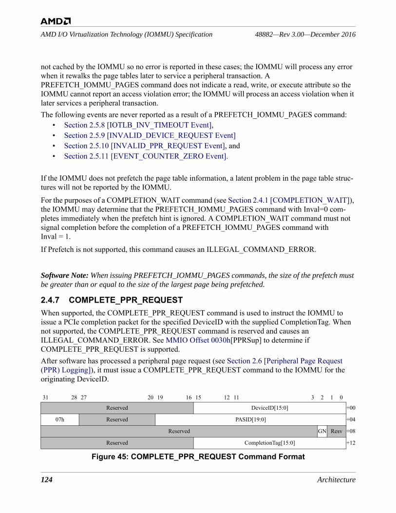
124 Architecture
48882—Rev 3.00—December 2016AMD I/O Virtualization Technology (IOMMU) Specification
not cached by the IOMMU so no error is reported in these cases; the IOMMU will process any error when it rewalks the page tables later to service a peripheral transaction. A PREFETCH_IOMMU_PAGES command does not indicate a read, write, or execute attribute so the IOMMU cannot report an access violation error; the IOMMU will process an access violation when it later services a peripheral transaction. The following events are never reported as a result of a PREFETCH_IOMMU_PAGES command:
• Section 2.5.8 [IOTLB_INV_TIMEOUT Event], • Section 2.5.9 [INVALID_DEVICE_REQUEST Event]• Section 2.5.10 [INVALID_PPR_REQUEST Event], and• Section 2.5.11 [EVENT_COUNTER_ZERO Event].
If the IOMMU does not prefetch the page table information, a latent problem in the page table struc-tures will not be reported by the IOMMU.For the purposes of a COMPLETION_WAIT command (see Section 2.4.1 [COMPLETION_WAIT]), the IOMMU may determine that the PREFETCH_IOMMU_PAGES command with Inval=0 com-pletes immediately when the prefetch hint is ignored. A COMPLETION_WAIT command must not signal completion before the completion of a PREFETCH_IOMMU_PAGES command with Inval = 1.If Prefetch is not supported, this command causes an ILLEGAL_COMMAND_ERROR.
Software Note: When issuing PREFETCH_IOMMU_PAGES commands, the size of the prefetch must be greater than or equal to the size of the largest page being prefetched.
2.4.7 COMPLETE_PPR_REQUESTWhen supported, the COMPLETE_PPR_REQUEST command is used to instruct the IOMMU to issue a PCIe completion packet for the specified DeviceID with the supplied CompletionTag. When not supported, the COMPLETE_PPR_REQUEST command is reserved and causes an ILLEGAL_COMMAND_ERROR. See MMIO Offset 0030h[PPRSup] to determine if COMPLETE_PPR_REQUEST is supported.After software has processed a peripheral page request (see Section 2.6 [Peripheral Page Request (PPR) Logging]), it must issue a COMPLETE_PPR_REQUEST command to the IOMMU for the originating DeviceID.
Figure 45: COMPLETE_PPR_REQUEST Command Format
31 28 27 20 19 16 15 12 11 3 2 1 0
Reserved DeviceID[15:0] +00
07h Reserved PASID[19:0] +04
Reserved GN Resv +08
Reserved CompletionTag[15:0] +12
Architecture 125
AMD I/O Virtualization Technology (IOMMU) Specification48882—Rev 3.00—December 2016
Software Note: The IOMMU does not validate the contents of the CompletionTag field. Software must use the PRI Page Request Group Index from the PPR request.
For GVA transactions, software should program GN=1, DeviceID, CompletionTag, and PASID. When GN=1, the IOMMU will insert the PASID into the PCIe TLP prefix. For GPA transactions, software should program GN=0, DeviceID, and CompletionTag. When GN=0, the PASID field is ignored by the IOMMU and no PCIe TLP prefix is inserted.If an error occurs while processing a COMPLETE_PPR_REQUEST command, it is reported in the event log (see Section 2.5.10 [INVALID_PPR_REQUEST Event]).The contents of Completion-Tag[15:0] depend on the peripheral bus type; only transactions for the PCIe bus are defined.
Table 40: COMPLETE_PPR_REQUEST FieldsBits Description31:16+00
Reserved.
15:0+00
DeviceID[15:0].
31:28+04
07h. COMPLETE_PPR_REQUEST command number.
27:20+04
Reserved.
19:0+04
PASID[19:0]. Must be zero when two-level translation is not enabled (see DTE[GV] in Table 7); ignored when GN=0.
31:3+08
Reserved.
2+08
GN: guest/nested. 0=PASID is ignored. 1=valid PASID. When two-level translation is not enabled, GN must be zero (see DTE[GV] in Table 7).
1:0+08
Reserved.
31:16+12
Reserved.
15:0+12
CompletionTag[15:0]. For PCIe: Comple-tionTag[15:12] contains the PRI Response Code, CompletionTag[11:9] must be zero and CompletionTag[8:0] contains the PRI Page Request Group Index taken from the PPRtag in the PAGE_SERVICE_REQUEST request entry (see Section 2.6.3 [Peripheral Page Request Entry]). For other bus types: Reserved.
CompletionTag[15:0]. For HyperTransport: Reserved.
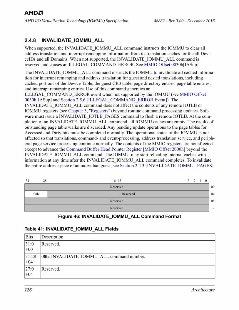
126 Architecture
48882—Rev 3.00—December 2016AMD I/O Virtualization Technology (IOMMU) Specification
2.4.8 INVALIDATE_IOMMU_ALLWhen supported, the INVALIDATE_IOMMU_ALL command instructs the IOMMU to clear all address translation and interrupt remapping information from its translation caches for the all Devi-ceIDs and all Domains. When not supported, the INVALIDATE_IOMMU_ALL command is reserved and causes an ILLEGAL_COMMAND_ERROR. See MMIO Offset 0030h[IASup].The INVALIDATE_IOMMU_ALL command instructs the IOMMU to invalidate all cached informa-tion for interrupt remapping and address translation for guest and nested translations, including cached portions of the Device Table, the guest CR3 table, page directory entries, page table entries, and interrupt remapping entries. Use of this command generates an ILLEGAL_COMMAND_ERROR event when not supported by the IOMMU (see MMIO Offset 0030h[IASup] and Section 2.5.6 [ILLEGAL_COMMAND_ERROR Event]). The INVALIDATE_IOMMU_ALL command does not affect the contents of any remote IOTLB or IOMMU registers (see Chapter 3, "Registers") beyond routine command processing updates. Soft-ware must issue a INVALIDATE_IOTLB_PAGES command to flush a remote IOTLB. At the com-pletion of an INVALIDATE_IOMMU_ALL command, all IOMMU caches are empty. The results of outstanding page table walks are discarded. Any pending update operations to the page tables for Accessed and Dirty bits must be completed normally. The operational status of the IOMMU is not affected so that translations, command- and event-processing, address translation service, and periph-eral page service processing continue normally. The contents of the MMIO registers are not affected except to advance the Command Buffer Head Pointer Register [MMIO Offset 2000h] beyond the INVALIDATE_IOMMU_ALL command. The IOMMU may start reloading internal caches with information at any time after the INVALIDATE_IOMMU_ALL command completes. To invalidate the entire address space of an individual guest, see Section 2.4.3 [INVALIDATE_IOMMU_PAGES].
Figure 46: INVALIDATE_IOMMU_ALL Command Format
31 28 16 15 3 2 1 0
Reserved +00
08h Reserved +04
Reserved +08
Reserved +12
Table 41: INVALIDATE_IOMMU_ALL FieldsBits Description31:0+00
Reserved.
31:28+04
08h. INVALIDATE_IOMMU_ALL command number.
27:0+04
Reserved.
Architecture 127
AMD I/O Virtualization Technology (IOMMU) Specification48882—Rev 3.00—December 2016
2.4.9 IOMMU Ordering RulesThe IOMMU must ensure that proper ordering is maintained between invalidation command types and between invalidation commands and the translation process.2.4.9.1 Invalidation Command Ordering RequirementsThe IOMMU must ensure that the following command ordering rules are followed for invalidation commands:• When an INVALIDATE_IOMMU_PAGES or INVALIDATE_INTERRUPT_TABLE command
is received, the IOMMU must ensure that all cache entries associated with any prior INVALIDATE_DEVTAB_ENTRY commands are invalidated from the cache before executing the command.
• When an INVALIDATE_IOTLB_PAGES command is received, the IOMMU must ensure that all cache entries associated with any prior INVALIDATE_DEVTAB_ENTRY or INVALIDATE_IOMMU_PAGES commands are invalidated from the cache before executing the command.
2.4.9.2 Invalidation Commands Interaction RequirementsInvalidation commands are considered completed only when the IOMMU can ensure that there are no DMA transactions in flight anywhere in the system fabric that relied on translation cache contents prior to the invalidation. To ensure that this property is achieved, the IOMMU must follow the fol-lowing rules:• The IOMMU must ensure that read responses for all DMA outstanding read transactions that
match the invalidation command have been received by the IOMMU. • HyperTransport™ tunnels that support address translation can achieve this property by
maintaining a counter that is incremented when a non-posted transaction is forwarded to the processor through the tunnel and is decremented when a response is forwarded from the processor through the tunnel. The invalidation command can be considered complete when the counter reaches zero. • The tunnel may temporarily block upstream traffic to cause the counter to resolve to zero
in a timely manner, ensuring that forward progress of the invalidation command is made.• The IOMMU must ensure that all DMA write transactions that have already been translated have
been pushed to the host bridge by:• Prior to sending the invalidation completion indication (interrupt or status write) the IOMMU
must:• Send an upstream Fence command in the base channel if the IOMMU supports translating
requests for more than one upstream stream (more than one unitID is in use).
31:0+08
Reserved.
31:0+12
Reserved.
Table 41: INVALIDATE_IOMMU_ALL Fields
128 Architecture
48882—Rev 3.00—December 2016AMD I/O Virtualization Technology (IOMMU) Specification
• Send an upstream Fence command followed by a Flush command in the isochronous channel if the IOMMU supports translating requests in both the isochronous and the base channels. The invalidation completion must wait for the Flush response to be received.
The IOMMU must ensure that both of these requirements are met prior to executing a subsequent COMPLETION_WAIT command.An invalidation command matches an outstanding translation if the command:
• Invalidates the Device Table entry for the I/O device that caused a translation to be initiated, or
• Invalidates the virtual address range being translated for a device.
2.5 Event LoggingThe IOMMU reports events to the host software by means of a shared circular buffer in system mem-ory. The IOMMU writes event records into the buffer. If the IOMMU needs to report an event but finds that the event log is already full, it sets MMIO Offset 2020h[EventOverflow]. The IOMMU can be configured to signal an interrupt whenever the event log is written or overflows using Capability Offset 10h[MsiNum]. The host software increments the IOMMU's head pointer to indicate to the IOMMU that it has consumed event log entries.When supported, the IOMMU generates event log entries for guest translations as well as host trans-lations using Capability Offset 10h[MsiNum]. Because some event reports are caused by hardware events that may make it impossible to update the event log, a set of MMIO registers has been defined to report selected event information. The IOMMU Hardware Event Upper Register [MMIO Offset 0040h] and IOMMU Hardware Event Lower Register [MMIO Offset 0048h] contain the same infor-mation found in an event log entry. The IOMMU Hardware Event Status Register [MMIO Offset 0050h] contains status bits that indicate that the information in the three registers is valid (HEV) and if an overflow has occurred (HEO). More information is contained in Section 2.5.12 [IOMMU Event Reporting].
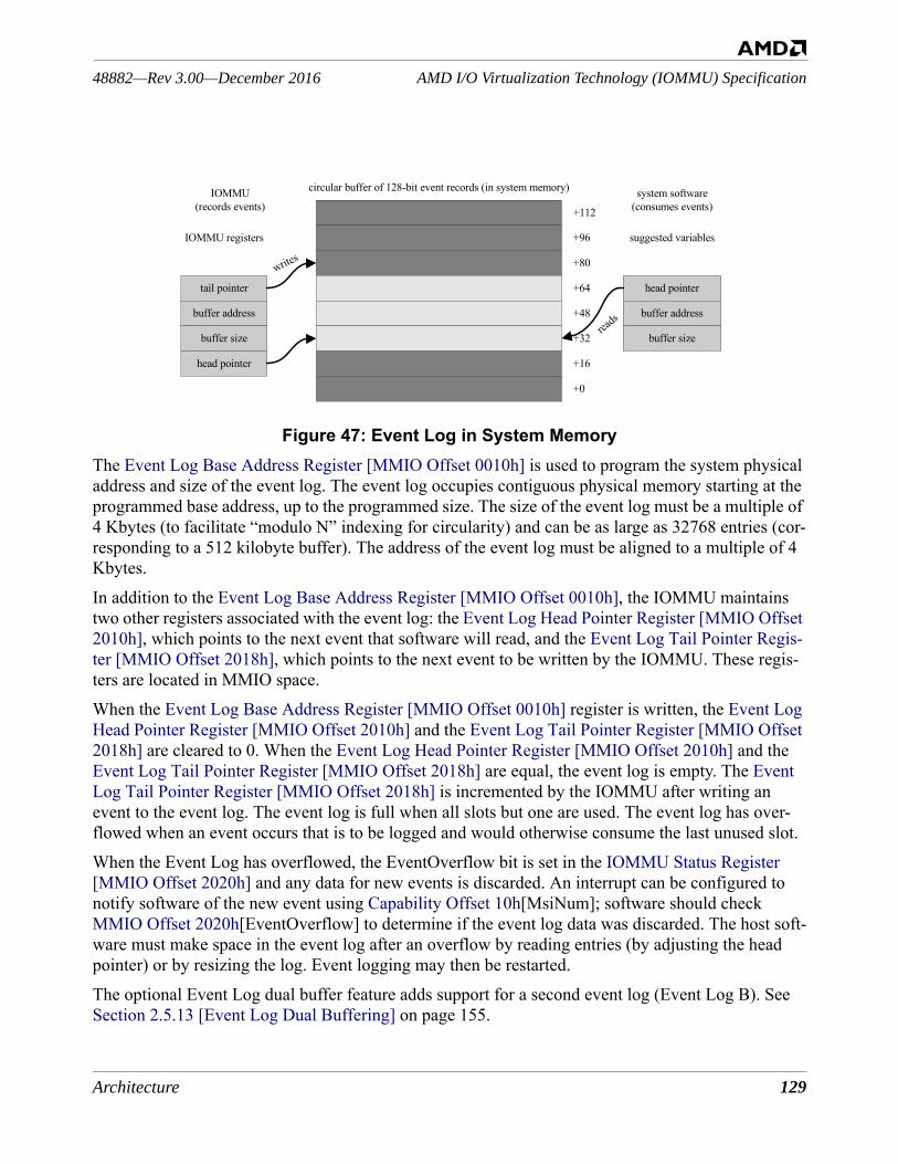
Architecture 129
AMD I/O Virtualization Technology (IOMMU) Specification48882—Rev 3.00—December 2016
Figure 47: Event Log in System MemoryThe Event Log Base Address Register [MMIO Offset 0010h] is used to program the system physical address and size of the event log. The event log occupies contiguous physical memory starting at the programmed base address, up to the programmed size. The size of the event log must be a multiple of 4 Kbytes (to facilitate “modulo N” indexing for circularity) and can be as large as 32768 entries (cor-responding to a 512 kilobyte buffer). The address of the event log must be aligned to a multiple of 4 Kbytes.In addition to the Event Log Base Address Register [MMIO Offset 0010h], the IOMMU maintains two other registers associated with the event log: the Event Log Head Pointer Register [MMIO Offset 2010h], which points to the next event that software will read, and the Event Log Tail Pointer Regis-ter [MMIO Offset 2018h], which points to the next event to be written by the IOMMU. These regis-ters are located in MMIO space. When the Event Log Base Address Register [MMIO Offset 0010h] register is written, the Event Log Head Pointer Register [MMIO Offset 2010h] and the Event Log Tail Pointer Register [MMIO Offset 2018h] are cleared to 0. When the Event Log Head Pointer Register [MMIO Offset 2010h] and the Event Log Tail Pointer Register [MMIO Offset 2018h] are equal, the event log is empty. The Event Log Tail Pointer Register [MMIO Offset 2018h] is incremented by the IOMMU after writing an event to the event log. The event log is full when all slots but one are used. The event log has over-flowed when an event occurs that is to be logged and would otherwise consume the last unused slot. When the Event Log has overflowed, the EventOverflow bit is set in the IOMMU Status Register [MMIO Offset 2020h] and any data for new events is discarded. An interrupt can be configured to notify software of the new event using Capability Offset 10h[MsiNum]; software should check MMIO Offset 2020h[EventOverflow] to determine if the event log data was discarded. The host soft-ware must make space in the event log after an overflow by reading entries (by adjusting the head pointer) or by resizing the log. Event logging may then be restarted.The optional Event Log dual buffer feature adds support for a second event log (Event Log B). See Section 2.5.13 [Event Log Dual Buffering] on page 155.
circular buffer of 128-bit event records (in system memory)
+112
+96
+80
+64
+48
+32
+16
+0
system software(consumes events)
IOMMU(records events)
tail pointer
writes
head pointer
read
s
suggested variablesIOMMU registers
buffer address
buffer size
buffer address
buffer size
head pointer
130 Architecture
48882—Rev 3.00—December 2016AMD I/O Virtualization Technology (IOMMU) Specification
2.5.1 Event Log Restart ProcedureThe IOMMU event logging is disabled after system reset and when the event log overflows. The IOMMU discards event reports until event logging is enabled, setting the EventOverflow bit in the IOMMU Status Register [MMIO Offset 2020h] to indicate the loss of event information. To restart the IOMMU event logging after the event log overflows, use the following procedure.• Wait until EventLogRun=0b in the IOMMU Status Register [MMIO Offset 2020h] so that all log
entries are completed as circumstances allow. EventLogRun must be 0b to modify the event log registers safely.
• Write EventLogEn=0b in the IOMMU Control Register [MMIO Offset 0018h].• As necessary, change the following registers (e.g., to relocate or resize the event log).
• the Event Log Base Address Register [MMIO Offset 0010h],• the Event Log Head Pointer Register [MMIO Offset 2010h], and • the Event Log Tail Pointer Register [MMIO Offset 2018h].
• Write the IOMMU Status Register [MMIO Offset 2020h] with EventOverflow = 1b to clear the bit (W1C).
• Write the IOMMU Control Register [MMIO Offset 0018h] with EventLogEn = 1b, and either set MMIO Offset 0018h[EventIntEn] to enable the Event log interrupt or clear the bit to disable it.
The IOMMU now creates event log entries for new events.
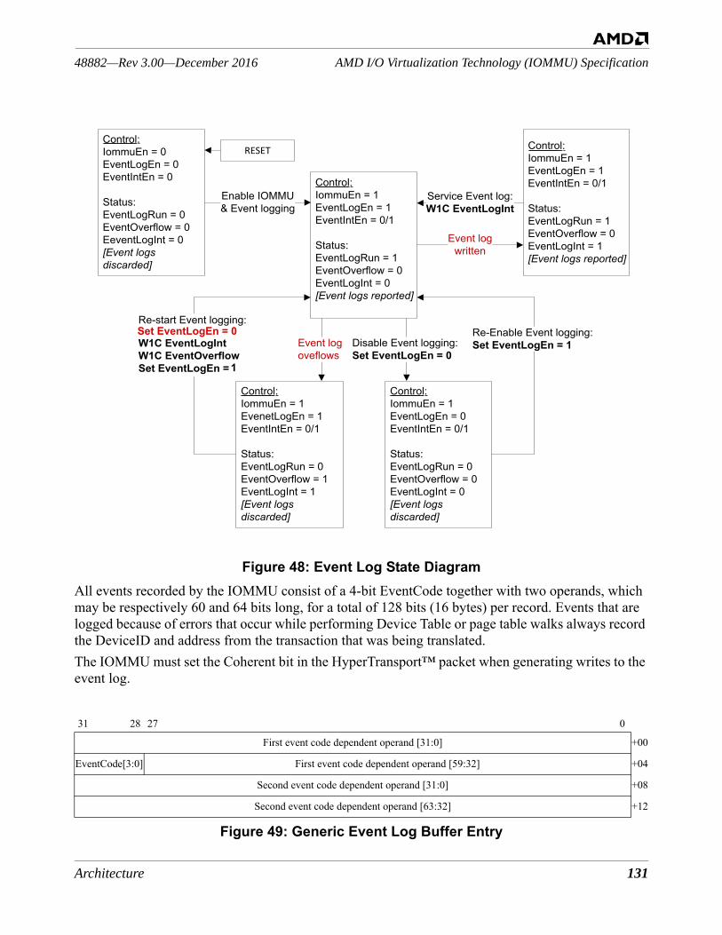
Architecture 131
AMD I/O Virtualization Technology (IOMMU) Specification48882—Rev 3.00—December 2016
Figure 48: Event Log State DiagramAll events recorded by the IOMMU consist of a 4-bit EventCode together with two operands, which may be respectively 60 and 64 bits long, for a total of 128 bits (16 bytes) per record. Events that are logged because of errors that occur while performing Device Table or page table walks always record the DeviceID and address from the transaction that was being translated.The IOMMU must set the Coherent bit in the HyperTransport™ packet when generating writes to the event log.
Figure 49: Generic Event Log Buffer Entry
31 28 27 0
First event code dependent operand [31:0] +00
EventCode[3:0] First event code dependent operand [59:32] +04
Second event code dependent operand [31:0] +08
Second event code dependent operand [63:32] +12
Set EventLogEn = 0
1
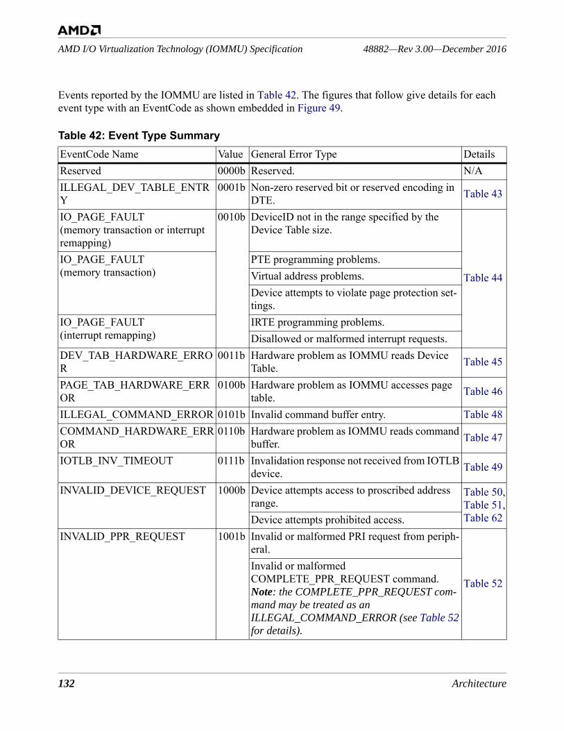
132 Architecture
48882—Rev 3.00—December 2016AMD I/O Virtualization Technology (IOMMU) Specification
Events reported by the IOMMU are listed in Table 42. The figures that follow give details for each event type with an EventCode as shown embedded in Figure 49.
Table 42: Event Type SummaryEventCode Name Value General Error Type DetailsReserved 0000b Reserved. N/AILLEGAL_DEV_TABLE_ENTRY
0001b Non-zero reserved bit or reserved encoding in DTE. Table 43
IO_PAGE_FAULT (memory transaction or interrupt remapping)
0010b DeviceID not in the range specified by the Device Table size.
Table 44IO_PAGE_FAULT (memory transaction)
PTE programming problems.Virtual address problems.Device attempts to violate page protection set-tings.
IO_PAGE_FAULT(interrupt remapping)
IRTE programming problems.Disallowed or malformed interrupt requests.
DEV_TAB_HARDWARE_ERROR
0011b Hardware problem as IOMMU reads Device Table. Table 45
PAGE_TAB_HARDWARE_ERROR
0100b Hardware problem as IOMMU accesses page table. Table 46
ILLEGAL_COMMAND_ERROR 0101b Invalid command buffer entry. Table 48COMMAND_HARDWARE_ERROR
0110b Hardware problem as IOMMU reads command buffer. Table 47
IOTLB_INV_TIMEOUT 0111b Invalidation response not received from IOTLB device. Table 49
INVALID_DEVICE_REQUEST 1000b Device attempts access to proscribed address range.
Table 50, Table 51,Table 62Device attempts prohibited access.
INVALID_PPR_REQUEST 1001b Invalid or malformed PRI request from periph-eral.
Table 52Invalid or malformed COMPLETE_PPR_REQUEST command.Note: the COMPLETE_PPR_REQUEST com-mand may be treated as an ILLEGAL_COMMAND_ERROR (see Table 52 for details).

Architecture 133
AMD I/O Virtualization Technology (IOMMU) Specification48882—Rev 3.00—December 2016
In Table 43 through Table 53, each event type is marked to show that it can be caused only by host software or by hardware.For details on ILLEGAL_DEV_TABLE_ENTRY events, see Section 2.5.2.
For details on IO_PAGE_FAULT events, see Section 2.5.3.
EVENT_COUNTER_ZERO 1001b Informational. Table 65Reserved 1010b-
1111bReserved; not used. N/A
Table 43: ILLEGAL_DEV_TABLE_ENTRY Event TypesEvent Type Cause IOMMU ResponseNon-zero reserved bit in a Device Table entry.
SW For a translation request or memory access, Target Abort transaction.For a command, abort the command.Create event log entry if enabled.Signal interrupt if enabled (see Capability Offset 10h[MsiNum]).
Reserved encoding in the IntTabLen field for a Device Table entry with IntCtl=10b.
SW
Reserved encoding in the IoCtl field. SWReserved encoding in the IntCtl field. SW
Table 42: Event Type SummaryEventCode Name Value General Error Type Details
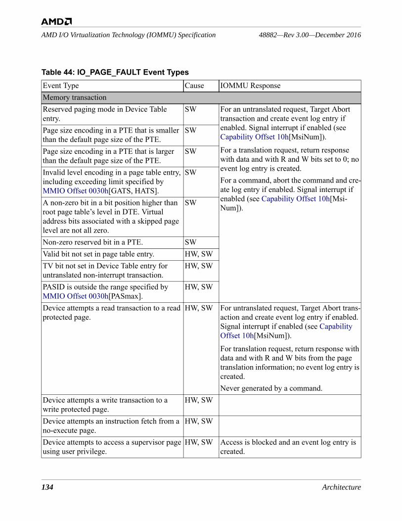
134 Architecture
48882—Rev 3.00—December 2016AMD I/O Virtualization Technology (IOMMU) Specification
Table 44: IO_PAGE_FAULT Event TypesEvent Type Cause IOMMU ResponseMemory transactionReserved paging mode in Device Table entry.
SW For an untranslated request, Target Abort transaction and create event log entry if enabled. Signal interrupt if enabled (see Capability Offset 10h[MsiNum]).For a translation request, return response with data and with R and W bits set to 0; no event log entry is created.For a command, abort the command and cre-ate log entry if enabled. Signal interrupt if enabled (see Capability Offset 10h[Msi-Num]).
Page size encoding in a PTE that is smaller than the default page size of the PTE.
SW
Page size encoding in a PTE that is larger than the default page size of the PTE.
SW
Invalid level encoding in a page table entry, including exceeding limit specified by MMIO Offset 0030h[GATS, HATS].
SW
A non-zero bit in a bit position higher than root page table’s level in DTE. Virtual address bits associated with a skipped page level are not all zero.
SW
Non-zero reserved bit in a PTE. SWValid bit not set in page table entry. HW, SWTV bit not set in Device Table entry for untranslated non-interrupt transaction.
HW, SW
PASID is outside the range specified by MMIO Offset 0030h[PASmax].
HW, SW
Device attempts a read transaction to a read protected page.
HW, SW For untranslated request, Target Abort trans-action and create event log entry if enabled. Signal interrupt if enabled (see Capability Offset 10h[MsiNum]).For translation request, return response with data and with R and W bits from the page translation information; no event log entry is created.Never generated by a command.
Device attempts a write transaction to a write protected page.
HW, SW
Device attempts an instruction fetch from a no-execute page.
HW, SW
Device attempts to access a supervisor page using user privilege.
HW, SW Access is blocked and an event log entry is created.

Architecture 135
AMD I/O Virtualization Technology (IOMMU) Specification48882—Rev 3.00—December 2016
For details on DEV_TAB_HARDWARE_ERROR events, see Section 2.5.4.
Interrupt remappingInterrupt request that addresses an IRTE that is beyond the end of the table.
HW, SW For interrupt transaction, Target Abort trans-action. Create event log entry if enabled. Signal interrupt if enabled (see Capability Offset 10h[MsiNum]).Never generated by a command.
Non-zero reserved bit in an IRTE. SWInterrupt request that targets an IRTE with RemapEn=0.
HW, SW
Interrupt request that targets an IRTE with reserved IntType.
SW
Interrupt request aborted by entry in Table 10 (Pass fields) or Table 19 (entries causing target abort).
HW, SW
Interrupt transaction with PASID. HWUpstream SMI request fails to match active SMI filter register (see Section 1.3.10 [SMI Filter]).
HW Create event log entry if enabled (see MMIO Offset 0018h[SmiFLogEn]). Signal interrupt if enabled (see Capability Offset 10h[MsiNum]).Never generated by a command.
Memory transaction or interrupt remappingDeviceID not in the range specified by the Device Table size.
HW For a translation request, Master Abort transaction.For a memory transaction, Target Abort transaction.For a command, abort the command.Create event log entry if enabled.Signal interrupt if enabled (see Capability Offset 10h[MsiNum]).
Table 44: IO_PAGE_FAULT Event Types (Continued)Event Type Cause IOMMU Response
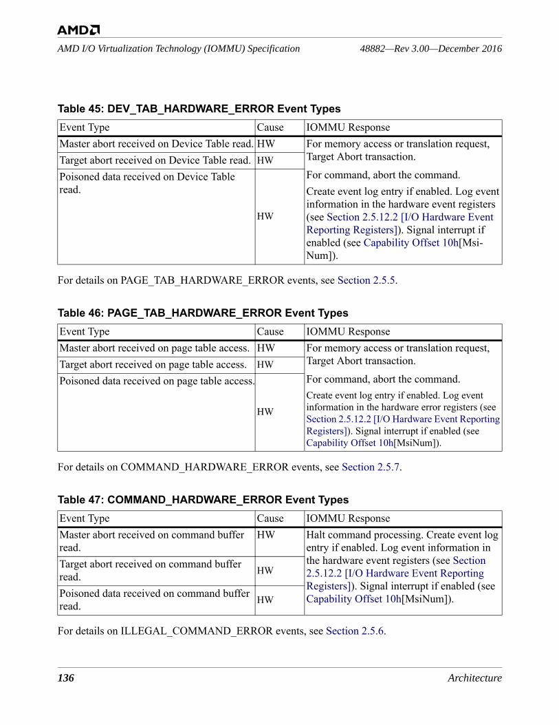
136 Architecture
48882—Rev 3.00—December 2016AMD I/O Virtualization Technology (IOMMU) Specification
For details on PAGE_TAB_HARDWARE_ERROR events, see Section 2.5.5.
For details on COMMAND_HARDWARE_ERROR events, see Section 2.5.7.
For details on ILLEGAL_COMMAND_ERROR events, see Section 2.5.6.
Table 45: DEV_TAB_HARDWARE_ERROR Event TypesEvent Type Cause IOMMU ResponseMaster abort received on Device Table read. HW For memory access or translation request,
Target Abort transaction.For command, abort the command.Create event log entry if enabled. Log event information in the hardware event registers (see Section 2.5.12.2 [I/O Hardware Event Reporting Registers]). Signal interrupt if enabled (see Capability Offset 10h[Msi-Num]).
Target abort received on Device Table read. HWPoisoned data received on Device Table read.
HW
Table 46: PAGE_TAB_HARDWARE_ERROR Event TypesEvent Type Cause IOMMU ResponseMaster abort received on page table access. HW For memory access or translation request,
Target Abort transaction.For command, abort the command.Create event log entry if enabled. Log event information in the hardware error registers (see Section 2.5.12.2 [I/O Hardware Event Reporting Registers]). Signal interrupt if enabled (see Capability Offset 10h[MsiNum]).
Target abort received on page table access. HWPoisoned data received on page table access.
HW
Table 47: COMMAND_HARDWARE_ERROR Event TypesEvent Type Cause IOMMU ResponseMaster abort received on command buffer read.
HW Halt command processing. Create event log entry if enabled. Log event information in the hardware event registers (see Section 2.5.12.2 [I/O Hardware Event Reporting Registers]). Signal interrupt if enabled (see Capability Offset 10h[MsiNum]).
Target abort received on command buffer read. HW
Poisoned data received on command buffer read. HW
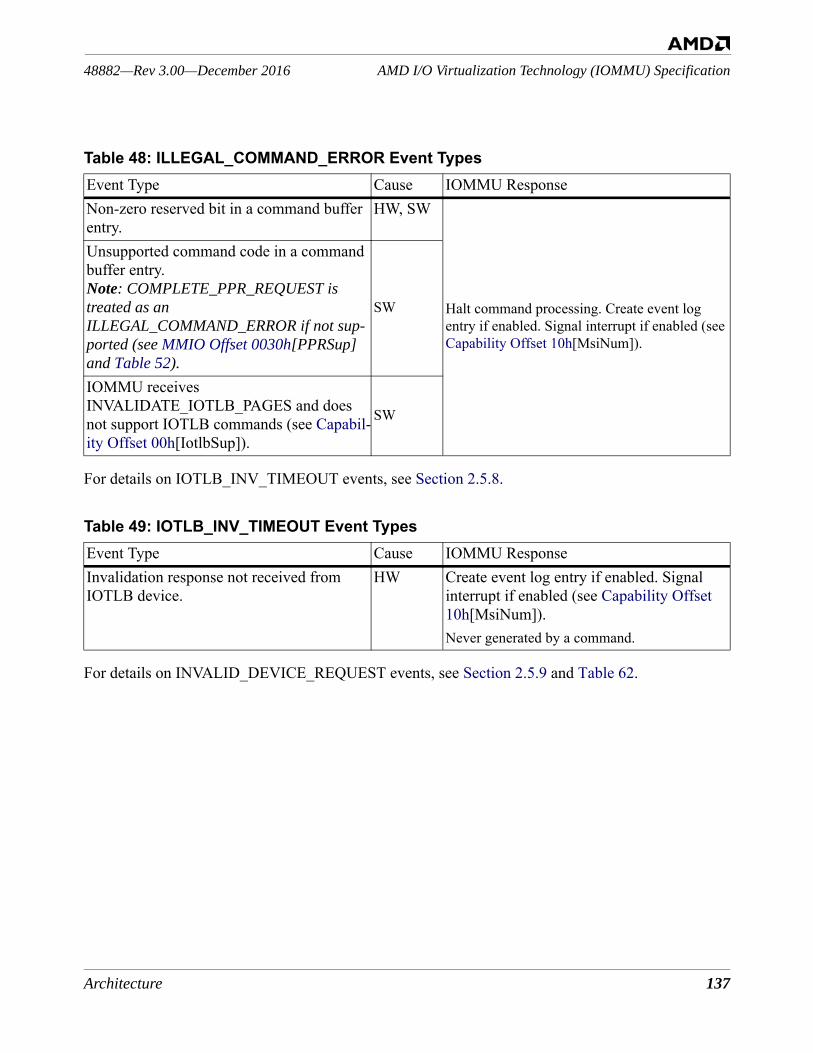
Architecture 137
AMD I/O Virtualization Technology (IOMMU) Specification48882—Rev 3.00—December 2016
For details on IOTLB_INV_TIMEOUT events, see Section 2.5.8.
For details on INVALID_DEVICE_REQUEST events, see Section 2.5.9 and Table 62.
Table 48: ILLEGAL_COMMAND_ERROR Event TypesEvent Type Cause IOMMU ResponseNon-zero reserved bit in a command buffer entry.
HW, SW
Halt command processing. Create event log entry if enabled. Signal interrupt if enabled (see Capability Offset 10h[MsiNum]).
Unsupported command code in a command buffer entry.Note: COMPLETE_PPR_REQUEST is treated as an ILLEGAL_COMMAND_ERROR if not sup-ported (see MMIO Offset 0030h[PPRSup] and Table 52).
SW
IOMMU receives INVALIDATE_IOTLB_PAGES and does not support IOTLB commands (see Capabil-ity Offset 00h[IotlbSup]).
SW
Table 49: IOTLB_INV_TIMEOUT Event TypesEvent Type Cause IOMMU ResponseInvalidation response not received from IOTLB device.
HW Create event log entry if enabled. Signal interrupt if enabled (see Capability Offset 10h[MsiNum]).Never generated by a command.
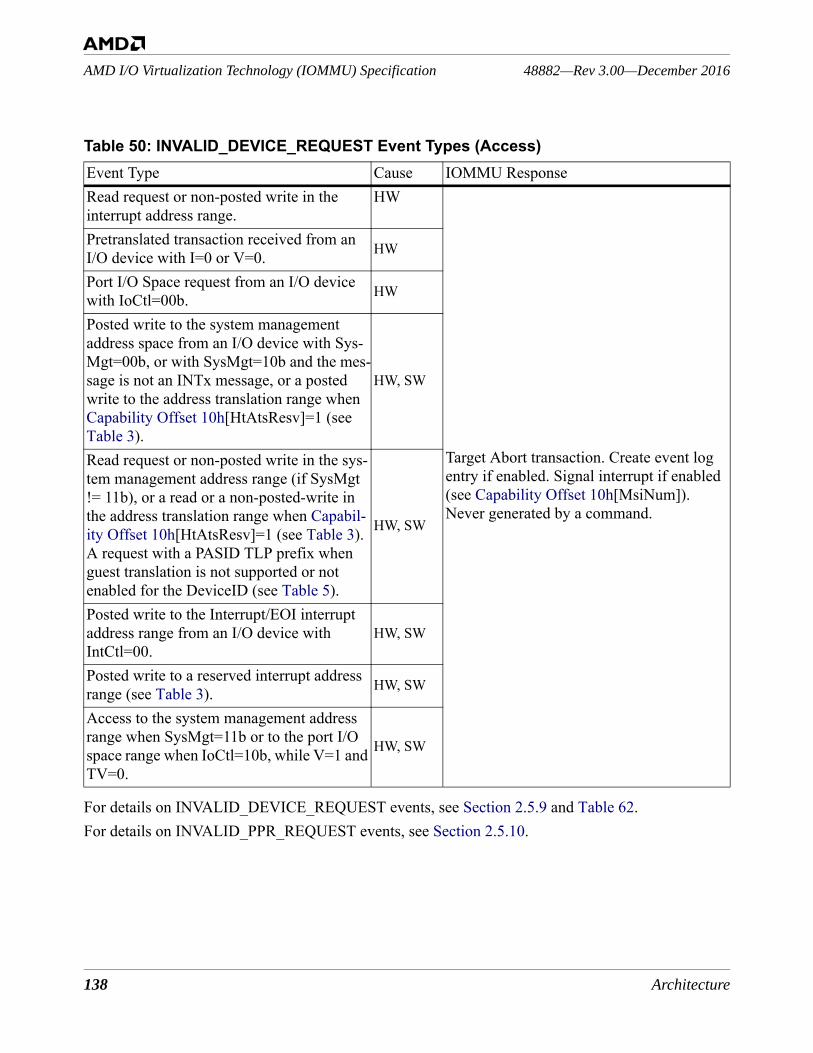
138 Architecture
48882—Rev 3.00—December 2016AMD I/O Virtualization Technology (IOMMU) Specification
For details on INVALID_DEVICE_REQUEST events, see Section 2.5.9 and Table 62.For details on INVALID_PPR_REQUEST events, see Section 2.5.10.
Table 50: INVALID_DEVICE_REQUEST Event Types (Access)Event Type Cause IOMMU ResponseRead request or non-posted write in the interrupt address range.
HW
Target Abort transaction. Create event log entry if enabled. Signal interrupt if enabled (see Capability Offset 10h[MsiNum]).Never generated by a command.
Pretranslated transaction received from an I/O device with I=0 or V=0. HW
Port I/O Space request from an I/O device with IoCtl=00b. HW
Posted write to the system management address space from an I/O device with Sys-Mgt=00b, or with SysMgt=10b and the mes-sage is not an INTx message, or a posted write to the address translation range when Capability Offset 10h[HtAtsResv]=1 (see Table 3).
HW, SW
Read request or non-posted write in the sys-tem management address range (if SysMgt != 11b), or a read or a non-posted-write in the address translation range when Capabil-ity Offset 10h[HtAtsResv]=1 (see Table 3). A request with a PASID TLP prefix when guest translation is not supported or not enabled for the DeviceID (see Table 5).
HW, SW
Posted write to the Interrupt/EOI interrupt address range from an I/O device with IntCtl=00.
HW, SW
Posted write to a reserved interrupt address range (see Table 3). HW, SW
Access to the system management address range when SysMgt=11b or to the port I/O space range when IoCtl=10b, while V=1 and TV=0.
HW, SW
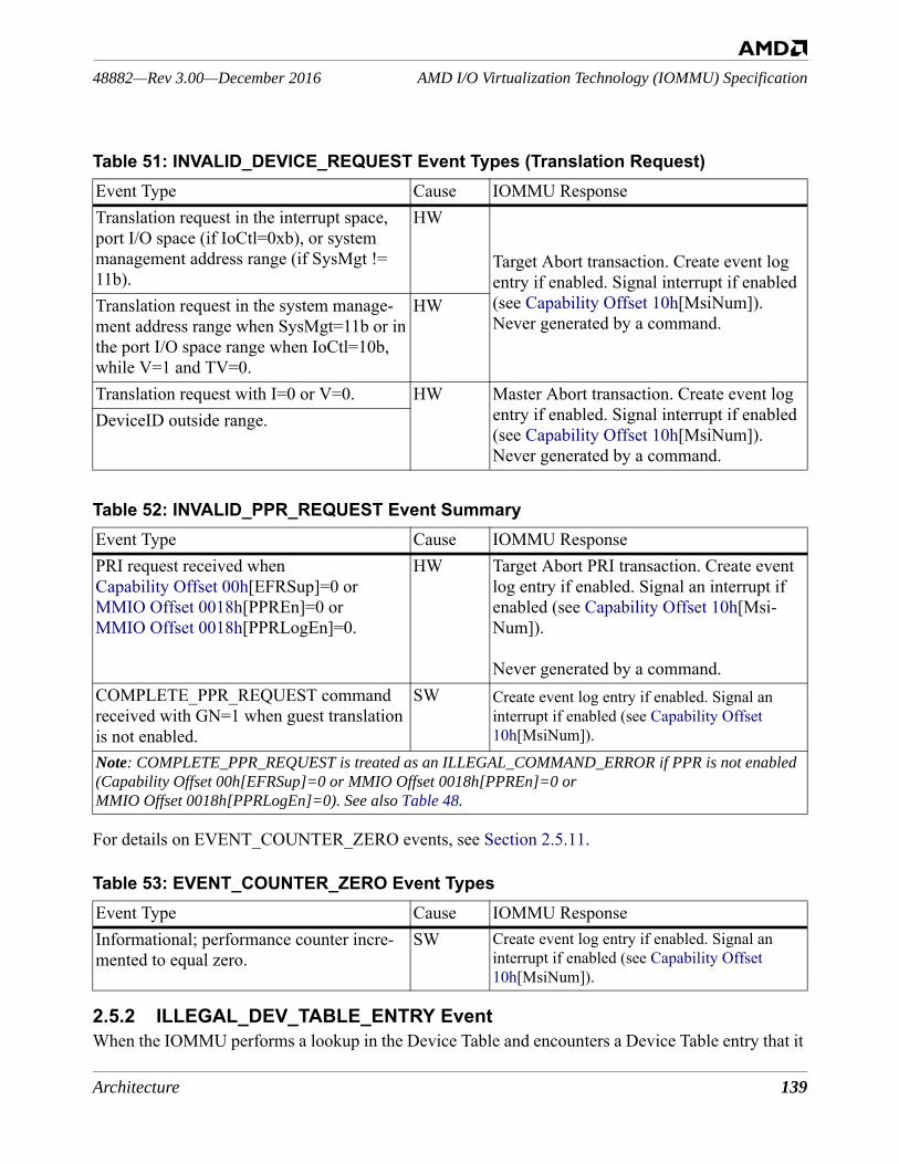
Architecture 139
AMD I/O Virtualization Technology (IOMMU) Specification48882—Rev 3.00—December 2016
For details on EVENT_COUNTER_ZERO events, see Section 2.5.11.
2.5.2 ILLEGAL_DEV_TABLE_ENTRY EventWhen the IOMMU performs a lookup in the Device Table and encounters a Device Table entry that it
Table 51: INVALID_DEVICE_REQUEST Event Types (Translation Request)Event Type Cause IOMMU ResponseTranslation request in the interrupt space, port I/O space (if IoCtl=0xb), or system management address range (if SysMgt != 11b).
HW
Target Abort transaction. Create event log entry if enabled. Signal interrupt if enabled (see Capability Offset 10h[MsiNum]).Never generated by a command.
Translation request in the system manage-ment address range when SysMgt=11b or in the port I/O space range when IoCtl=10b, while V=1 and TV=0.
HW
Translation request with I=0 or V=0. HW Master Abort transaction. Create event log entry if enabled. Signal interrupt if enabled (see Capability Offset 10h[MsiNum]).Never generated by a command.
DeviceID outside range.
Table 52: INVALID_PPR_REQUEST Event SummaryEvent Type Cause IOMMU ResponsePRI request received when Capability Offset 00h[EFRSup]=0 or MMIO Offset 0018h[PPREn]=0 or MMIO Offset 0018h[PPRLogEn]=0.
HW Target Abort PRI transaction. Create event log entry if enabled. Signal an interrupt if enabled (see Capability Offset 10h[Msi-Num]).
Never generated by a command.COMPLETE_PPR_REQUEST command received with GN=1 when guest translation is not enabled.
SW Create event log entry if enabled. Signal an interrupt if enabled (see Capability Offset 10h[MsiNum]).
Note: COMPLETE_PPR_REQUEST is treated as an ILLEGAL_COMMAND_ERROR if PPR is not enabled (Capability Offset 00h[EFRSup]=0 or MMIO Offset 0018h[PPREn]=0 or MMIO Offset 0018h[PPRLogEn]=0). See also Table 48.
Table 53: EVENT_COUNTER_ZERO Event TypesEvent Type Cause IOMMU ResponseInformational; performance counter incre-mented to equal zero.
SW Create event log entry if enabled. Signal an interrupt if enabled (see Capability Offset 10h[MsiNum]).

140 Architecture
48882—Rev 3.00—December 2016AMD I/O Virtualization Technology (IOMMU) Specification
does not support or that is formatted incorrectly, the IOMMU writes an ILLEGAL_DEV_TABLE_ENTRY event to the event log as listed in Table 43.
Figure 50: ILLEGAL_DEV_TABLE_ENTRY Event Log Buffer Entry Format
31 28 27 25 24 23 22 21 20 19 18 17 16 15 2 1 0
Reserved PASID[19:16] DeviceID[15:0] +00
0001b Reserved TR RZ ResRWRes I Res GN PASID[15:0] +04
Address[31:2] Res +08
Address[63:32] +12
Table 54: ILLEGAL_DEV_TABLE_ENTRY Event Log Buffer Entry FieldsBits Description31:20 +00
Reserved.
31:20 +00
PASID[19:16]: process space ID. The guest PASID[19:16] from the transaction when GN=1; 0h when GN=0.
15:0 +00
DeviceID. Specifies the DeviceID that caused the Device Table lookup. The address of the malformed Device Table entry can be determined using the DeviceID field.
31:28 +04
0001b. Specifies an ILLEGAL_DEV_TABLE_ENTRY.
27:25 +04
Reserved.
24 +04
TR: translation. 1=transaction that caused the Device Table lookup was a translation request. 0=transaction that caused the Device Table lookup was a transaction request.
23+04
RZ: reserved bit not zero or invalid level encoding. 1=I/O page fault was caused by a non-zero reserved bit in the Device Table entry. 0=I/O page fault was caused by an invalid level encoding in the Device Table entry.
22+04
Reserved.
21+04
RW: read-write. 1=transaction that caused the Device Table lookup was a write. 0=transac-tion that caused the Device Table lookup was a read. RW is only meaningful when TR=0 and I=0.
20+04
Reserved.
19+04
I: interrupt. 1=transaction that caused the Device Table lookup was an interrupt request. 0=transaction that caused the Device Table lookup was a memory request.
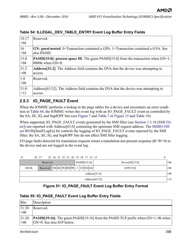
Architecture 141
AMD I/O Virtualization Technology (IOMMU) Specification48882—Rev 3.00—December 2016
2.5.3 IO_PAGE_FAULT EventWhen the IOMMU performs a lookup in the page tables for a device and encounters an error condi-tion in Table 44, the IOMMU writes the event log with an IO_PAGE_FAULT event as controlled by the SA, SE, IG, and SupIOPF bits (see Figure 7 and Table 7 or Figure 15 and Table 10).When supported, IO_PAGE_FAULT events generated by the SMI filter (see Section 1.3.10 [SMI Fil-ter]) are reported with Address[63:0] containing the upstream SMI request address. The MMIO Off-set 0018h[SmiFLogEn] bit controls the logging of IO_PAGE_FAULT events reported by the SMI filter; the SA, SE, IG, and SupIOPF bits do not affect SMI filter logging.I/O page faults detected for translation requests return a translation-not-present response (R=W=0) to the device and are not logged in the event log.
Figure 51: IO_PAGE_FAULT Event Log Buffer Entry Format
18:17+04
Reserved.
16+04
GN: guest/nested. 0=Transaction contained a GPA. 1=Transaction contained a GVA. See also PASID.
15:0+04
PASID[15:0]: process space ID. The guest PASID[15:0] from the transaction when GN=1; 0000h when GN=0.
31:2+08
Address[31:2]. The Address field contains the DVA that the device was attempting to access.
1:0+08
Reserved.
31:0+12
Address[63:32]. The Address field contains the DVA that the device was attempting to access.
31 28 27 25 24 23 22 21 20 19 18 17 16 15 0
Reserved PASID[19:16] DeviceID[15:0] +00
0010b Reserved TR RZ PE RW PR I US NX GN D/P[15:0] +04
Address[31:0] +08
Address[63:32] +12
Table 55: IO_PAGE_FAULT Event Log Buffer Entry FieldsBits Description31:20+00
Reserved.
31:20+00
PASID[19:16]. The guest PASID[19:16] from the PASID TLP prefix when GN=1; 0h when GN=0. See also D/P below.
Table 54: ILLEGAL_DEV_TABLE_ENTRY Event Log Buffer Entry Fields
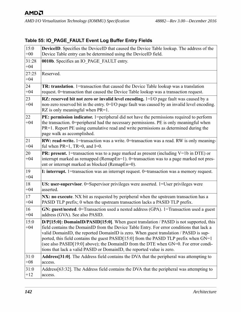
142 Architecture
48882—Rev 3.00—December 2016AMD I/O Virtualization Technology (IOMMU) Specification
15:0+00
DeviceID. Specifies the DeviceID that caused the Device Table lookup. The address of the Device Table entry can be determined using the DeviceID field.
31:28+04
0010b. Specifies an IO_PAGE_FAULT entry.
27:25+04
Reserved.
24 +04
TR: translation. 1=transaction that caused the Device Table lookup was a translation request. 0=transaction that caused the Device Table lookup was a transaction request.
23+04
RZ: reserved bit not zero or invalid level encoding. 1=I/O page fault was caused by a non-zero reserved bit in the entry. 0=I/O page fault was caused by an invalid level encoding. RZ is only meaningful when PR=1.
22+04
PE: permission indicator. 1=peripheral did not have the permissions required to perform the transaction. 0=peripheral had the necessary permissions. PE is only meaningful when PR=1. Report PE using cumulative read and write permissions as determined during the page walk as accomplished.
21+04
RW: read-write. 1=transaction was a write. 0=transaction was a read. RW is only meaning-ful when PR=1, TR=0, and I=0.
20+04
PR: present. 1=transaction was to a page marked as present (including V=1b in DTE) or interrupt marked as remapped (RemapEn=1). 0=transaction was to a page marked not pres-ent or interrupt marked as blocked (RemapEn=0).
19+04
I: interrupt. 1=transaction was an interrupt request. 0=transaction was a memory request.
18+04
US: user-supervisor. 0=Supervisor privileges were asserted. 1=User privileges were asserted.
17+04
NX: no execute. NX bit as requested by peripheral when the upstream transaction has a PASID TLP prefix; 0 when the upstream transaction lacks a PASID TLP prefix.
16+04
GN: guest/nested. 0=Transaction used a nested address (GPA). 1=Transaction used a guest address (GVA). See also PASID.
15:0+04
D/P[15:0]: DomainID/PASID[15:0]. When guest translation / PASID is not supported, this field contains the DomainID from the Device Table Entry. For error conditions that lack a valid DomainID, the reported DomainID is zero. When guest translation / PASID is sup-ported, this field contains the guest PASID[15:0] from the PASID TLP prefix when GN=1 (see also PASID[19:0] above); the DomainID from the DTE when GN=0. For error condi-tions that lack a valid PASID or DomainID, the reported value is zero.
31:0+08
Address[31:0]. The Address field contains the DVA that the peripheral was attempting to access.
31:0+12
Address[63:32]. The Address field contains the DVA that the peripheral was attempting to access.
Table 55: IO_PAGE_FAULT Event Log Buffer Entry Fields
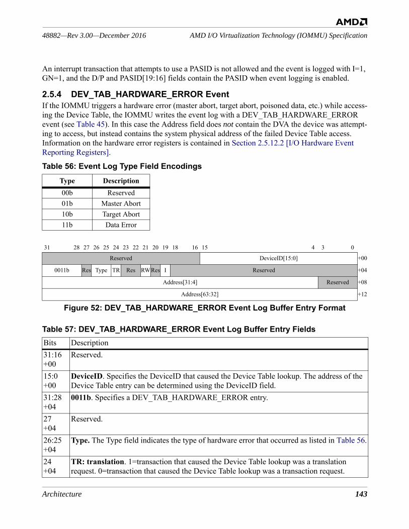
Architecture 143
AMD I/O Virtualization Technology (IOMMU) Specification48882—Rev 3.00—December 2016
An interrupt transaction that attempts to use a PASID is not allowed and the event is logged with I=1, GN=1, and the D/P and PASID[19:16] fields contain the PASID when event logging is enabled.
2.5.4 DEV_TAB_HARDWARE_ERROR EventIf the IOMMU triggers a hardware error (master abort, target abort, poisoned data, etc.) while access-ing the Device Table, the IOMMU writes the event log with a DEV_TAB_HARDWARE_ERROR event (see Table 45). In this case the Address field does not contain the DVA the device was attempt-ing to access, but instead contains the system physical address of the failed Device Table access. Information on the hardware error registers is contained in Section 2.5.12.2 [I/O Hardware Event Reporting Registers].
Figure 52: DEV_TAB_HARDWARE_ERROR Event Log Buffer Entry Format
Table 56: Event Log Type Field EncodingsType Description00b Reserved01b Master Abort10b Target Abort11b Data Error
31 28 27 26 25 24 23 22 21 20 19 18 16 15 4 3 0
Reserved DeviceID[15:0] +00
0011b Res Type TR Res RWRes I Reserved +04
Address[31:4] Reserved +08
Address[63:32] +12
Table 57: DEV_TAB_HARDWARE_ERROR Event Log Buffer Entry FieldsBits Description31:16 +00
Reserved.
15:0 +00
DeviceID. Specifies the DeviceID that caused the Device Table lookup. The address of the Device Table entry can be determined using the DeviceID field.
31:28 +04
0011b. Specifies a DEV_TAB_HARDWARE_ERROR entry.
27+04
Reserved.
26:25+04
Type. The Type field indicates the type of hardware error that occurred as listed in Table 56.
24 +04
TR: translation. 1=transaction that caused the Device Table lookup was a translation request. 0=transaction that caused the Device Table lookup was a transaction request.
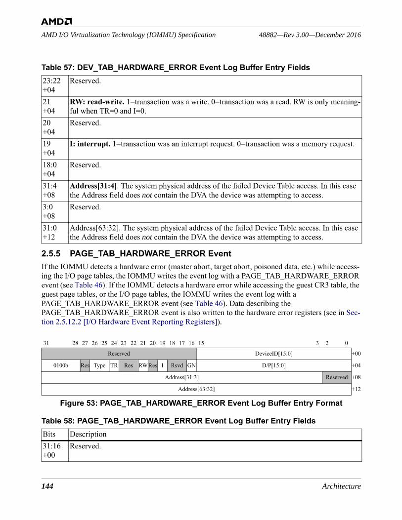
144 Architecture
48882—Rev 3.00—December 2016AMD I/O Virtualization Technology (IOMMU) Specification
2.5.5 PAGE_TAB_HARDWARE_ERROR EventIf the IOMMU detects a hardware error (master abort, target abort, poisoned data, etc.) while access-ing the I/O page tables, the IOMMU writes the event log with a PAGE_TAB_HARDWARE_ERROR event (see Table 46). If the IOMMU detects a hardware error while accessing the guest CR3 table, the guest page tables, or the I/O page tables, the IOMMU writes the event log with a PAGE_TAB_HARDWARE_ERROR event (see Table 46). Data describing the PAGE_TAB_HARDWARE_ERROR event is also written to the hardware error registers (see in Sec-tion 2.5.12.2 [I/O Hardware Event Reporting Registers]).
Figure 53: PAGE_TAB_HARDWARE_ERROR Event Log Buffer Entry Format
23:22+04
Reserved.
21+04
RW: read-write. 1=transaction was a write. 0=transaction was a read. RW is only meaning-ful when TR=0 and I=0.
20+04
Reserved.
19+04
I: interrupt. 1=transaction was an interrupt request. 0=transaction was a memory request.
18:0+04
Reserved.
31:4+08
Address[31:4]. The system physical address of the failed Device Table access. In this case the Address field does not contain the DVA the device was attempting to access.
3:0+08
Reserved.
31:0+12
Address[63:32]. The system physical address of the failed Device Table access. In this case the Address field does not contain the DVA the device was attempting to access.
31 28 27 26 25 24 23 22 21 20 19 18 17 16 15 3 2 0
Reserved DeviceID[15:0] +00
0100b Res Type TR Res RWRes I Rsvd GN D/P[15:0] +04
Address[31:3] Reserved +08
Address[63:32] +12
Table 58: PAGE_TAB_HARDWARE_ERROR Event Log Buffer Entry FieldsBits Description31:16 +00
Reserved.
Table 57: DEV_TAB_HARDWARE_ERROR Event Log Buffer Entry Fields
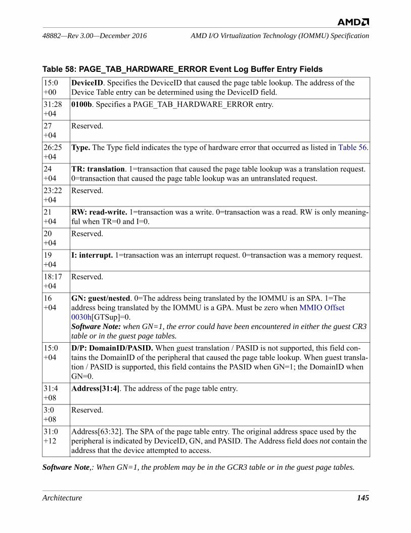
Architecture 145
AMD I/O Virtualization Technology (IOMMU) Specification48882—Rev 3.00—December 2016
Software Note,: When GN=1, the problem may be in the GCR3 table or in the guest page tables.
15:0 +00
DeviceID. Specifies the DeviceID that caused the page table lookup. The address of the Device Table entry can be determined using the DeviceID field.
31:28 +04
0100b. Specifies a PAGE_TAB_HARDWARE_ERROR entry.
27+04
Reserved.
26:25+04
Type. The Type field indicates the type of hardware error that occurred as listed in Table 56.
24 +04
TR: translation. 1=transaction that caused the page table lookup was a translation request. 0=transaction that caused the page table lookup was an untranslated request.
23:22+04
Reserved.
21+04
RW: read-write. 1=transaction was a write. 0=transaction was a read. RW is only meaning-ful when TR=0 and I=0.
20+04
Reserved.
19+04
I: interrupt. 1=transaction was an interrupt request. 0=transaction was a memory request.
18:17+04
Reserved.
16+04
GN: guest/nested. 0=The address being translated by the IOMMU is an SPA. 1=The address being translated by the IOMMU is a GPA. Must be zero when MMIO Offset 0030h[GTSup]=0.Software Note: when GN=1, the error could have been encountered in either the guest CR3 table or in the guest page tables.
15:0+04
D/P: DomainID/PASID. When guest translation / PASID is not supported, this field con-tains the DomainID of the peripheral that caused the page table lookup. When guest transla-tion / PASID is supported, this field contains the PASID when GN=1; the DomainID when GN=0.
31:4+08
Address[31:4]. The address of the page table entry.
3:0+08
Reserved.
31:0+12
Address[63:32]. The SPA of the page table entry. The original address space used by the peripheral is indicated by DeviceID, GN, and PASID. The Address field does not contain the address that the device attempted to access.
Table 58: PAGE_TAB_HARDWARE_ERROR Event Log Buffer Entry Fields
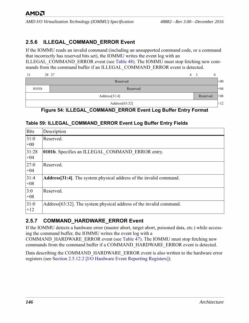
146 Architecture
48882—Rev 3.00—December 2016AMD I/O Virtualization Technology (IOMMU) Specification
2.5.6 ILLEGAL_COMMAND_ERROR EventIf the IOMMU reads an invalid command (including an unsupported command code, or a command that incorrectly has reserved bits set), the IOMMU writes the event log with an ILLEGAL_COMMAND_ERROR event (see Table 48). The IOMMU must stop fetching new com-mands from the command buffer if an ILLEGAL_COMMAND_ERROR event is detected.
2.5.7 COMMAND_HARDWARE_ERROR EventIf the IOMMU detects a hardware error (master abort, target abort, poisoned data, etc.) while access-ing the command buffer, the IOMMU writes the event log with a COMMAND_HARDWARE_ERROR event (see Table 47). The IOMMU must stop fetching new commands from the command buffer if a COMMAND_HARDWARE_ERROR event is detected.Data describing the COMMAND_HARDWARE_ERROR event is also written to the hardware error registers (see Section 2.5.12.2 [I/O Hardware Event Reporting Registers]).
31 28 27 4 3 0
Reserved +00
0101b Reserved +04
Address[31:4] Reserved +08
Address[63:32] +12
Figure 54: ILLEGAL_COMMAND_ERROR Event Log Buffer Entry Format
Table 59: ILLEGAL_COMMAND_ERROR Event Log Buffer Entry FieldsBits Description31:0 +00
Reserved.
31:28 +04
0101b. Specifies an ILLEGAL_COMMAND_ERROR entry.
27:0+04
Reserved.
31:4+08
Address[31:4]. The system physical address of the invalid command.
3:0+08
Reserved.
31:0+12
Address[63:32]. The system physical address of the invalid command.
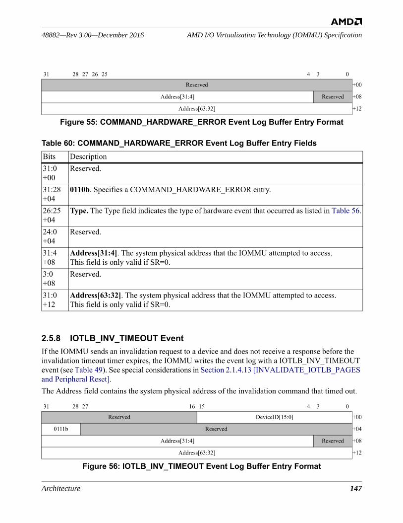
Architecture 147
AMD I/O Virtualization Technology (IOMMU) Specification48882—Rev 3.00—December 2016
Figure 55: COMMAND_HARDWARE_ERROR Event Log Buffer Entry Format
2.5.8 IOTLB_INV_TIMEOUT EventIf the IOMMU sends an invalidation request to a device and does not receive a response before the invalidation timeout timer expires, the IOMMU writes the event log with a IOTLB_INV_TIMEOUT event (see Table 49). See special considerations in Section 2.1.4.13 [INVALIDATE_IOTLB_PAGES and Peripheral Reset].The Address field contains the system physical address of the invalidation command that timed out.
Figure 56: IOTLB_INV_TIMEOUT Event Log Buffer Entry Format
31 28 27 26 25 4 3 0
Reserved +00
Address[31:4] Reserved +08
Address[63:32] +12
Table 60: COMMAND_HARDWARE_ERROR Event Log Buffer Entry FieldsBits Description31:0 +00
Reserved.
31:28 +04
0110b. Specifies a COMMAND_HARDWARE_ERROR entry.
26:25+04
Type. The Type field indicates the type of hardware event that occurred as listed in Table 56.
24:0+04
Reserved.
31:4+08
Address[31:4]. The system physical address that the IOMMU attempted to access.This field is only valid if SR=0.
3:0+08
Reserved.
31:0+12
Address[63:32]. The system physical address that the IOMMU attempted to access.This field is only valid if SR=0.
31 28 27 16 15 4 3 0
Reserved DeviceID[15:0] +00
0111b Reserved +04
Address[31:4] Reserved +08
Address[63:32] +12
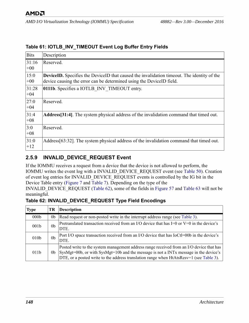
148 Architecture
48882—Rev 3.00—December 2016AMD I/O Virtualization Technology (IOMMU) Specification
2.5.9 INVALID_DEVICE_REQUEST EventIf the IOMMU receives a request from a device that the device is not allowed to perform, the IOMMU writes the event log with a INVALID_DEVICE_REQUEST event (see Table 50). Creation of event log entries for INVALID_DEVICE_REQUEST events is controlled by the IG bit in the Device Table entry (Figure 7 and Table 7). Depending on the type of the INVALID_DEVICE_REQUEST (Table 62), some of the fields in Figure 57 and Table 63 will not be meaningful.
Table 61: IOTLB_INV_TIMEOUT Event Log Buffer Entry FieldsBits Description31:16+00
Reserved.
15:0+00
DeviceID. Specifies the DeviceID that caused the invalidation timeout. The identity of the device causing the error can be determined using the DeviceID field.
31:28 +04
0111b. Specifies a IOTLB_INV_TIMEOUT entry.
27:0+04
Reserved.
31:4+08
Address[31:4]. The system physical address of the invalidation command that timed out.
3:0+08
Reserved.
31:0+12
Address[63:32]. The system physical address of the invalidation command that timed out.
Table 62: INVALID_DEVICE_REQUEST Type Field EncodingsType TR Description
000b 0b Read request or non-posted write in the interrupt address range (see Table 3).
001b 0b Pretranslated transaction received from an I/O device that has I=0 or V=0 in the device’s DTE.
010b 0b Port I/O space transaction received from an I/O device that has IoCtl=00b in the device’s DTE.
011b 0bPosted write to the system management address range received from an I/O device that has SysMgt=00b, or with SysMgt=10b and the message is not a INTx message in the device’s DTE, or a posted write to the address translation range when HtAtsResv=1 (see Table 3).
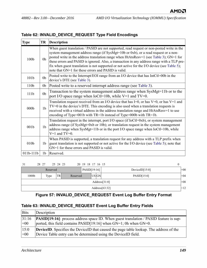
Architecture 149
AMD I/O Virtualization Technology (IOMMU) Specification48882—Rev 3.00—December 2016
Figure 57: INVALID_DEVICE_REQUEST Event Log Buffer Entry Format
100b 0b
When guest translation / PASID are not supported, read request or non-posted write in the system management address range (if SysMgt=10b or 0xb), or a read request or a non-posted write in the address translation range when HtAtsResv=1 (see Table 3); GN=1 for these errors and PASID is ignored. Also, a transaction in any address range with a TLP pre-fix when guest translation is not supported or not active for the I/O device (see Table 5); note that GN=1 for these errors and PASID is valid.
101b 0b Posted write to the Interrupt/EOI range from an I/O device that has IntCtl=00b in the device’s DTE (see Table 3).
110b 0b Posted write to a reserved interrupt address range (see Table 3).
111b 0b Transaction to the system management address range when SysMgt=11b or to the port I/O space range when IoCtl=10b, while V=1 and TV=0.
000b 1b
Translation request received from an I/O device that has I=0, or has V=0, or has V=1 and TV=0 in the device’s DTE. This encoding is also used when a translation requests is received with a virtual address in the address translation range and HtAtsResv=1 to use encoding of Type=001b with TR=1b instead of Type=000b with TR=1b.
001b 1b
Translation request in the interrupt, port I/O space (if IoCtl=0xb), or system management address range (if SysMgt=0xb or 10b); or translation request in the system management address range when SysMgt=11b or in the port I/O space range when IoCtl=10b, while V=1 and TV=0.
010b 1bWhen PASID is supported, a translation request for any address with a TLP prefix when guest translation is not supported or not active for the I/O device (see Table 5); note that GN=1 for these errors and PASID is valid.
011b-111b 1b Reserved.
31 28 27 25 24 23 20 19 18 17 16 15 0
Reserved PASID[19:16] DeviceID[15:0] +00
1000b Type TR Reserved US GN PASID[15:0] +04
Address[31:0] +08
Address[63:32] +12
Table 63: INVALID_DEVICE_REQUEST Event Log Buffer Entry FieldsBits Description31:16 +00
PASID[19:16]: process address space ID. When guest translation / PASID feature is sup-ported, this field contains PASID[19:16] when GN=1; 0h when GN=0.
15:0+00
DeviceID. Specifies the DeviceID that caused the page table lookup. The address of the Device Table entry can be determined using the DeviceID field.
Table 62: INVALID_DEVICE_REQUEST Type Field EncodingsType TR Description
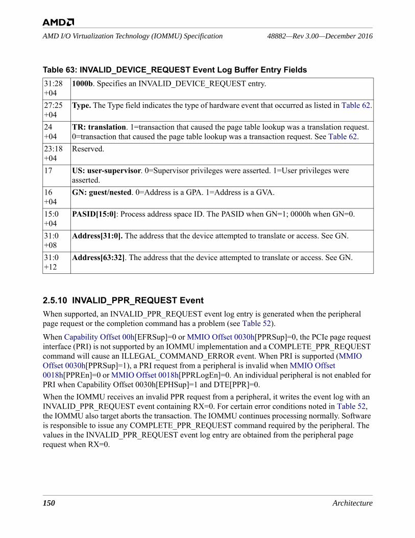
150 Architecture
48882—Rev 3.00—December 2016AMD I/O Virtualization Technology (IOMMU) Specification
2.5.10 INVALID_PPR_REQUEST EventWhen supported, an INVALID_PPR_REQUEST event log entry is generated when the peripheral page request or the completion command has a problem (see Table 52). When Capability Offset 00h[EFRSup]=0 or MMIO Offset 0030h[PPRSup]=0, the PCIe page request interface (PRI) is not supported by an IOMMU implementation and a COMPLETE_PPR_REQUEST command will cause an ILLEGAL_COMMAND_ERROR event. When PRI is supported (MMIO Offset 0030h[PPRSup]=1), a PRI request from a peripheral is invalid when MMIO Offset 0018h[PPREn]=0 or MMIO Offset 0018h[PPRLogEn]=0. An individual peripheral is not enabled for PRI when Capability Offset 0030h[EPHSup]=1 and DTE[PPR]=0.When the IOMMU receives an invalid PPR request from a peripheral, it writes the event log with an INVALID_PPR_REQUEST event containing RX=0. For certain error conditions noted in Table 52, the IOMMU also target aborts the transaction. The IOMMU continues processing normally. Software is responsible to issue any COMPLETE_PPR_REQUEST command required by the peripheral. The values in the INVALID_PPR_REQUEST event log entry are obtained from the peripheral page request when RX=0.
31:28 +04
1000b. Specifies an INVALID_DEVICE_REQUEST entry.
27:25+04
Type. The Type field indicates the type of hardware event that occurred as listed in Table 62.
24+04
TR: translation. 1=transaction that caused the page table lookup was a translation request. 0=transaction that caused the page table lookup was a transaction request. See Table 62.
23:18+04
Reserved.
17 US: user-supervisor. 0=Supervisor privileges were asserted. 1=User privileges were asserted.
16+04
GN: guest/nested. 0=Address is a GPA. 1=Address is a GVA.
15:0+04
PASID[15:0]: Process address space ID. The PASID when GN=1; 0000h when GN=0.
31:0+08
Address[31:0]. The address that the device attempted to translate or access. See GN.
31:0+12
Address[63:32]. The address that the device attempted to translate or access. See GN.
Table 63: INVALID_DEVICE_REQUEST Event Log Buffer Entry Fields
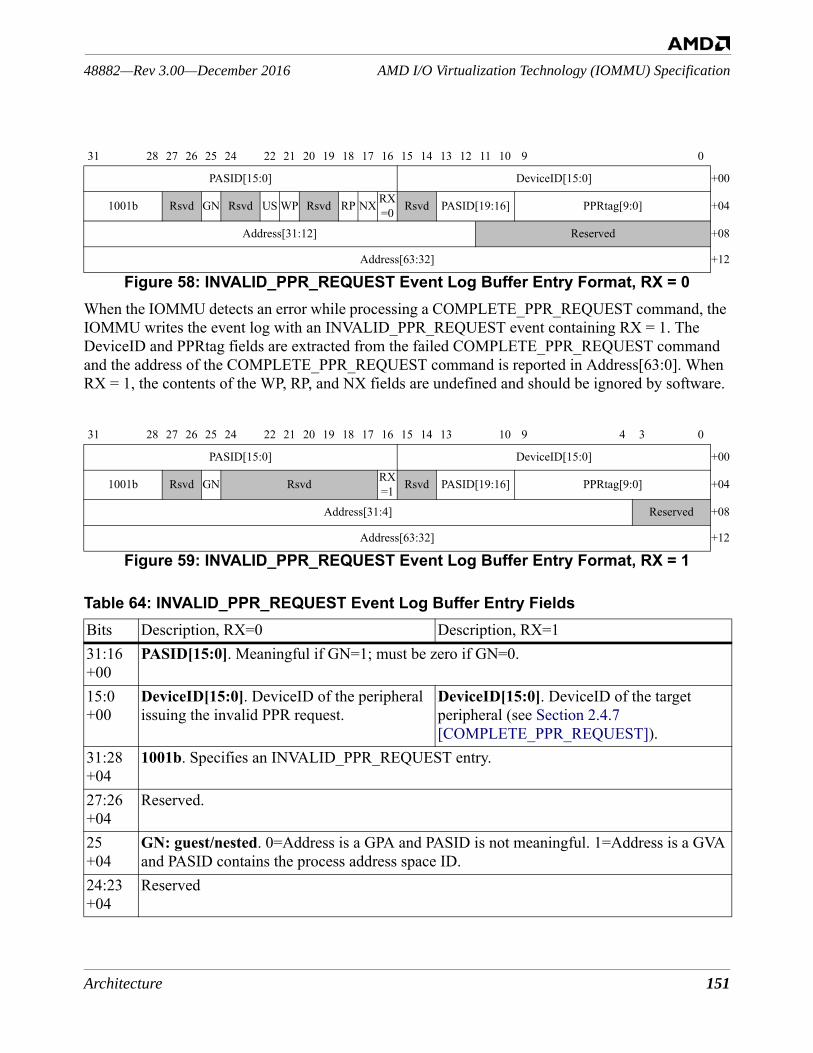
Architecture 151
AMD I/O Virtualization Technology (IOMMU) Specification48882—Rev 3.00—December 2016
When the IOMMU detects an error while processing a COMPLETE_PPR_REQUEST command, the IOMMU writes the event log with an INVALID_PPR_REQUEST event containing RX = 1. The DeviceID and PPRtag fields are extracted from the failed COMPLETE_PPR_REQUEST command and the address of the COMPLETE_PPR_REQUEST command is reported in Address[63:0]. When RX = 1, the contents of the WP, RP, and NX fields are undefined and should be ignored by software.
31 28 27 26 25 24 22 21 20 19 18 17 16 15 14 13 12 11 10 9 0
PASID[15:0] DeviceID[15:0] +00
1001b Rsvd GN Rsvd US WP Rsvd RP NX RX=0 Rsvd PASID[19:16] PPRtag[9:0] +04
Address[31:12] Reserved +08
Address[63:32] +12
Figure 58: INVALID_PPR_REQUEST Event Log Buffer Entry Format, RX = 0
31 28 27 26 25 24 22 21 20 19 18 17 16 15 14 13 10 9 4 3 0
PASID[15:0] DeviceID[15:0] +00
1001b Rsvd GN Rsvd RX=1 Rsvd PASID[19:16] PPRtag[9:0] +04
Address[31:4] Reserved +08
Address[63:32] +12
Figure 59: INVALID_PPR_REQUEST Event Log Buffer Entry Format, RX = 1
Table 64: INVALID_PPR_REQUEST Event Log Buffer Entry FieldsBits Description, RX=0 Description, RX=131:16 +00
PASID[15:0]. Meaningful if GN=1; must be zero if GN=0.
15:0+00
DeviceID[15:0]. DeviceID of the peripheral issuing the invalid PPR request.
DeviceID[15:0]. DeviceID of the target peripheral (see Section 2.4.7 [COMPLETE_PPR_REQUEST]).
31:28 +04
1001b. Specifies an INVALID_PPR_REQUEST entry.
27:26+04
Reserved.
25+04
GN: guest/nested. 0=Address is a GPA and PASID is not meaningful. 1=Address is a GVA and PASID contains the process address space ID.
24:23+04
Reserved

152 Architecture
48882—Rev 3.00—December 2016AMD I/O Virtualization Technology (IOMMU) Specification
Software Note: Software is responsible to take the PCI PRG index from the PPRtag field and use it in the PPR completion command (see Section 2.4.7 [COMPLETE_PPR_REQUEST]).
22+04
US. User/supervisor bit as received from the peripheral. See PMR in Table 33.
Reserved.
21+04
WP. Write permission request bit as received from the peripheral.
Reserved.
20:19+04
Reserved.
18+04
RP. Read permission request bit as received from the peripheral.
Reserved.
17+04
NX. No-execute permission request bit as received from the peripheral. See Exe in Table 33
Reserved.
16+04
RX. 0=Invalid PAGE_SERVICE_REQUEST received (see Section 2.6.3 [Peripheral Page Request Entry]).
RX. 1=COMPLETE_PPR_REQUEST failed (see Section 2.4.7 [COMPLETE_PPR_REQUEST]).
15:14+04
Reserved.
13:10+04
PASID[19:16]. Meaningful if GN=1; must be zero if GN=0.
9:0+04
PPRtag[9:0]. The PPRtag field as received from the peripheral. This field contains a pro-tocol-dependent tag. • When the PPR request originated as a
PCIe page request message, PPRtag[9] is the L bit and PPRtag[8:0] is the PRG index.
PPRtag[9:0]. The PPRtag field as sent to the peripheral. This field contains a protocol-dependent tag. • When the PPR completion targets a PCIe
peripheral, PPRtag[9] is the L bit and PPRtag[8:0] is the PRG index.
• The PRI Response Code in is not reported (see Table 40).
31:12+08
Address[31:12]. The page address as received from the peripheral.
Address[31:4]. The SPA of the invalid PPR completion command.
11:4+08
Reserved.
3:0+08
Reserved.
31:0+12
Address[63:32]. The page address as received from the peripheral.
Address[63:32]. The SPA of the invalid PPR completion command.
Table 64: INVALID_PPR_REQUEST Event Log Buffer Entry Fields
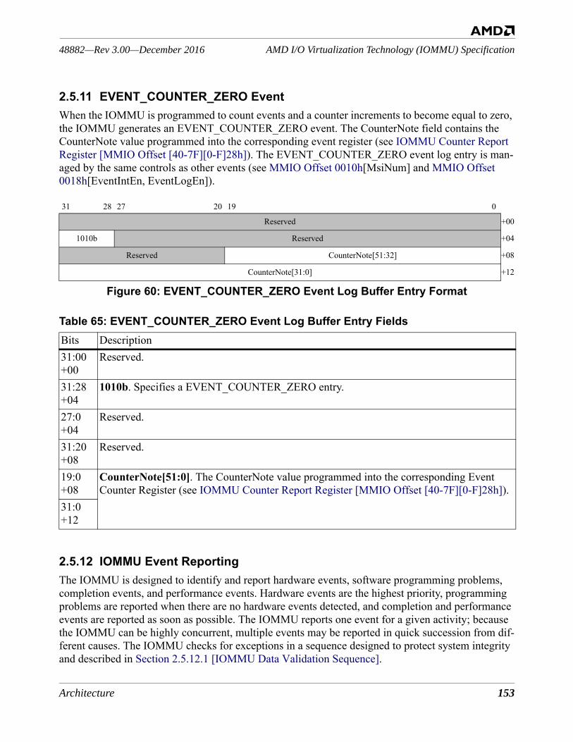
Architecture 153
AMD I/O Virtualization Technology (IOMMU) Specification48882—Rev 3.00—December 2016
2.5.11 EVENT_COUNTER_ZERO EventWhen the IOMMU is programmed to count events and a counter increments to become equal to zero, the IOMMU generates an EVENT_COUNTER_ZERO event. The CounterNote field contains the CounterNote value programmed into the corresponding event register (see IOMMU Counter Report Register [MMIO Offset [40-7F][0-F]28h]). The EVENT_COUNTER_ZERO event log entry is man-aged by the same controls as other events (see MMIO Offset 0010h[MsiNum] and MMIO Offset 0018h[EventIntEn, EventLogEn]).
Figure 60: EVENT_COUNTER_ZERO Event Log Buffer Entry Format
2.5.12 IOMMU Event ReportingThe IOMMU is designed to identify and report hardware events, software programming problems, completion events, and performance events. Hardware events are the highest priority, programming problems are reported when there are no hardware events detected, and completion and performance events are reported as soon as possible. The IOMMU reports one event for a given activity; because the IOMMU can be highly concurrent, multiple events may be reported in quick succession from dif-ferent causes. The IOMMU checks for exceptions in a sequence designed to protect system integrity and described in Section 2.5.12.1 [IOMMU Data Validation Sequence].
31 28 27 20 19 0
Reserved +00
1010b Reserved +04
Reserved CounterNote[51:32] +08
CounterNote[31:0] +12
Table 65: EVENT_COUNTER_ZERO Event Log Buffer Entry FieldsBits Description31:00+00
Reserved.
31:28 +04
1010b. Specifies a EVENT_COUNTER_ZERO entry.
27:0+04
Reserved.
31:20+08
Reserved.
19:0+08
CounterNote[51:0]. The CounterNote value programmed into the corresponding Event Counter Register (see IOMMU Counter Report Register [MMIO Offset [40-7F][0-F]28h]).
31:0+12
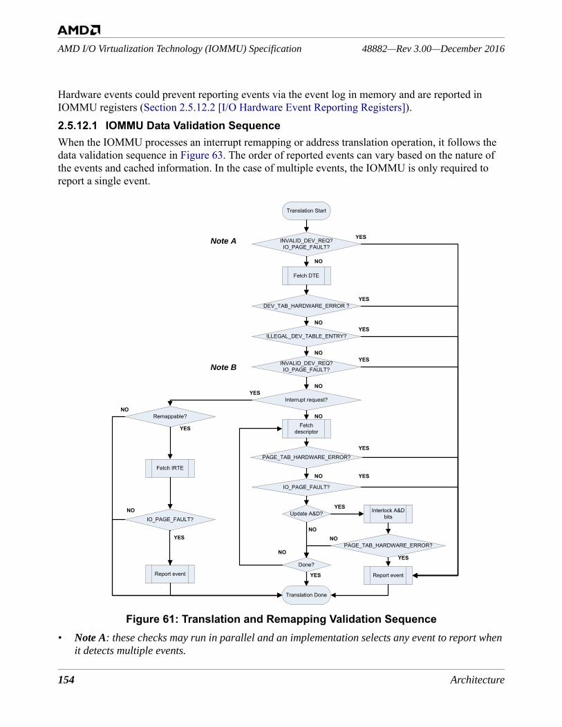
154 Architecture
48882—Rev 3.00—December 2016AMD I/O Virtualization Technology (IOMMU) Specification
Hardware events could prevent reporting events via the event log in memory and are reported in IOMMU registers (Section 2.5.12.2 [I/O Hardware Event Reporting Registers]).2.5.12.1 IOMMU Data Validation SequenceWhen the IOMMU processes an interrupt remapping or address translation operation, it follows the data validation sequence in Figure 63. The order of reported events can vary based on the nature of the events and cached information. In the case of multiple events, the IOMMU is only required to report a single event.
Figure 61: Translation and Remapping Validation Sequence• Note A: these checks may run in parallel and an implementation selects any event to report when
it detects multiple events.
NO
YES
NO
NO
NO
NO
NO
NO
NO
NO
NO
NO
YES
YES
YES
YES
YES
YES
YES
YES
YES
YES
YES
Fetch DTE
DEV_TAB_HARDWARE_ERROR ?
ILLEGAL_DEV_TABLE_ENTRY?
Fetch descriptor
PAGE_TAB_HARDWARE_ERROR?
IO_PAGE_FAULT?
Done?
Translation Done
Translation Start
Interlock A&D bitsUpdate A&D?
PAGE_TAB_HARDWARE_ERROR?
Report event
INVALID_DEV_REQ?IO_PAGE_FAULT?
INVALID_DEV_REQ?IO_PAGE_FAULT?
Report event
Interrupt request?
Remappable?
Fetch IRTE
IO_PAGE_FAULT?
Note A
Note B
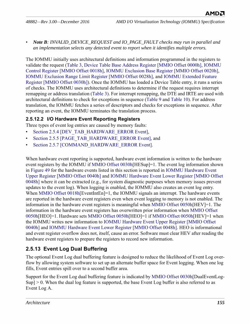
Architecture 155
AMD I/O Virtualization Technology (IOMMU) Specification48882—Rev 3.00—December 2016
• Note B: INVALID_DEVICE_REQUEST and IO_PAGE_FAULT checks may run in parallel and an implementation selects any detected event to report when it identifies multiple errors.
The IOMMU initially uses architectural definitions and information programmed in the registers to validate the request (Table 3, Device Table Base Address Register [MMIO Offset 0000h], IOMMU Control Register [MMIO Offset 0018h], IOMMU Exclusion Base Register [MMIO Offset 0020h], IOMMU Exclusion Range Limit Register [MMIO Offset 0028h], and IOMMU Extended Feature Register [MMIO Offset 0030h]). Once the IOMMU has loaded a Device Table entry, it runs a series of checks. The IOMMU uses architectural definitions to determine if the request requires interrupt remapping or address translation (Table 3). For interrupt remapping, the DTE and IRTE are used with architectural definitions to check for exceptions in sequence (Table 9 and Table 10). For address translation, the IOMMU fetches a series of descriptors and checks for exceptions in sequence. After reporting an event, the IOMMU terminates the translation process.2.5.12.2 I/O Hardware Event Reporting RegistersThree types of event log entries are caused by memory faults:• Section 2.5.4 [DEV_TAB_HARDWARE_ERROR Event], • Section 2.5.5 [PAGE_TAB_HARDWARE_ERROR Event], and • Section 2.5.7 [COMMAND_HARDWARE_ERROR Event].
When hardware event reporting is supported, hardware event information is written to the hardware event registers by the IOMMU if MMIO Offset 0030h[HESup]=1. The event log information shown in Figure 49 for the hardware events listed in this section is reported in IOMMU Hardware Event Upper Register [MMIO Offset 0040h] and IOMMU Hardware Event Lower Register [MMIO Offset 0048h] where it can be extracted (e.g., for system diagnostic purposes when memory issues prevent updates to the event log). When logging is enabled, the IOMMU also creates an event log entry. When MMIO Offset 0018h[EventIntEn]=1, the IOMMU signals an interrupt. The hardware events are reported in the hardware event registers even when event logging to memory is not enabled. The information in the hardware event registers is meaningful when MMIO Offset 0050h[HEV]=1. The information in the hardware event registers has overwritten prior information when MMIO Offset 0050h[HEO]=1. Hardware sets MMIO Offset 0050h[HEO]=1 if MMIO Offset 0050h[HEV]=1 when the IOMMU writes new information to IOMMU Hardware Event Upper Register [MMIO Offset 0040h] and IOMMU Hardware Event Lower Register [MMIO Offset 0048h]. HEO is informational and event register overflow does not, itself, cause an error. Software must clear HEV after reading the hardware event registers to prepare the registers to record new information.
2.5.13 Event Log Dual BufferingThe optional Event Log dual buffering feature is designed to reduce the likelihood of Event Log over-flow by allowing system software to set up an alternate buffer space for Event logging. When one log fills, Event entries spill over to a second buffer area.Support for the Event Log dual buffering feature is indicated by MMIO Offset 0030h[DualEventLog-Sup] > 0. When the dual log feature is supported, the base Event Log buffer is also referred to as Event Log A.
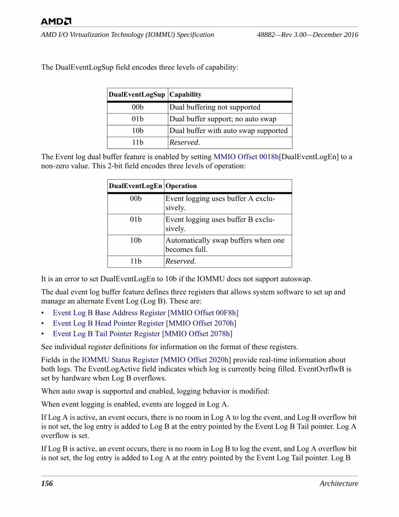
156 Architecture
48882—Rev 3.00—December 2016AMD I/O Virtualization Technology (IOMMU) Specification
The DualEventLogSup field encodes three levels of capability:
The Event log dual buffer feature is enabled by setting MMIO Offset 0018h[DualEventLogEn] to a non-zero value. This 2-bit field encodes three levels of operation:
It is an error to set DualEventLogEn to 10b if the IOMMU does not support autoswap.The dual event log buffer feature defines three registers that allows system software to set up and manage an alternate Event Log (Log B). These are:• Event Log B Base Address Register [MMIO Offset 00F8h]• Event Log B Head Pointer Register [MMIO Offset 2070h]• Event Log B Tail Pointer Register [MMIO Offset 2078h]See individual register definitions for information on the format of these registers.Fields in the IOMMU Status Register [MMIO Offset 2020h] provide real-time information about both logs. The EventLogActive field indicates which log is currently being filled. EventOvrflwB is set by hardware when Log B overflows.When auto swap is supported and enabled, logging behavior is modified: When event logging is enabled, events are logged in Log A.If Log A is active, an event occurs, there is no room in Log A to log the event, and Log B overflow bit is not set, the log entry is added to Log B at the entry pointed by the Event Log B Tail pointer. Log A overflow is set. If Log B is active, an event occurs, there is no room in Log B to log the event, and Log A overflow bit is not set, the log entry is added to Log A at the entry pointed by the Event Log Tail pointer. Log B
DualEventLogSup Capability
00b Dual buffering not supported01b Dual buffer support; no auto swap10b Dual buffer with auto swap supported11b Reserved.
DualEventLogEn Operation
00b Event logging uses buffer A exclu-sively.
01b Event logging uses buffer B exclu-sively.
10b Automatically swap buffers when one becomes full.
11b Reserved.
Architecture 157
AMD I/O Virtualization Technology (IOMMU) Specification48882—Rev 3.00—December 2016
overflow is set. Note: If the overflow bit of the log to be swapped to is set when a log swap is about to occur, an error is logged.
2.6 Peripheral Page Request (PPR) LoggingSome ATS-capable peripherals can issue requests to the processor to service peripheral page requests using PCIe PRI, the Page Request Interface (see the PCI Address Translation Services Revision 1.1 specification). An IOMMU that supports peripheral page requests (MMIO Offset 0030h[PPR-Sup]=1b) can report these requests to the host software by means of a shared circular buffer in system memory. The IOMMU writes peripheral page request (PPR) records into the buffer when enabled by MMIO Offset 0018h[PPREn]. The host software increments the IOMMU's PPR request log head pointer to indicate to the IOMMU that it has consumed PPR request log entries. When software has completed processing the PPR request, it uses the IOMMU COMPLETE_PPR_REQUEST command to inform the peripheral of the results (see Section 2.4.7 [COMPLETE_PPR_REQUEST]).Software Note: The IOMMU cannot service PRI requests without software intervention, so it con-verts them to PPR log entries for software to process. All PRI requests are converted to PPR log entries as long as there is room in the PPR log while MMIO Offset 0018h[PPRLogEn] = 1. To stop the IOMMU from processing all PRI requests, software can program MMIO Offset 0018h[PPRLogEn] = 0; this causes PRI requests to be discarded by the IOMMU. To stop an individ-ual peripheral from issuing PRI requests, software must use the control fields in the peripheral regis-ters.
Figure 62: Peripheral Page Request Log in System MemoryThe PPR Log Base Address Register [MMIO Offset 0038h] is used to program the system physical address and size of the PPR log. The PPR log occupies contiguous physical memory starting at the programmed base address up to the programmed size. The size of the PPR log must be a multiple of 4 Kbytes (to facilitate “modulo N” indexing for circularity) and can be as large as 32768 entries (cor-responding to a 512 kilobyte buffer). The base address of the PPR log must be aligned to a multiple of 4 Kbytes.In addition to the PPR Log Base Address Register [MMIO Offset 0038h], the IOMMU maintains two
circular buffer of 128-bit event records (in system memory)
+112
+96
+80
+64
+48
+32
+16
+0
system software(consumes requests)
IOMMU(records peripheral page fault
requests)
tail pointer
writes
head pointer
read
s
suggested variablesIOMMU registers
buffer address
buffer size
buffer address
buffer size
head pointer
158 Architecture
48882—Rev 3.00—December 2016AMD I/O Virtualization Technology (IOMMU) Specification
other registers associated with the PPR log: the IOMMU PPR Log Head Pointer Register [MMIO Offset 2030h], which points to the next PPR request that software will read, and the IOMMU PPR Log Tail Pointer Register [MMIO Offset 2038h], which points to the next PPR request to be written by the IOMMU. These registers are located in MMIO space. When the PPR Log Base Address Register [MMIO Offset 0038h] register is written, the IOMMU PPR Log Head Pointer Register [MMIO Offset 2030h] and the IOMMU PPR Log Tail Pointer Regis-ter [MMIO Offset 2038h] are cleared to 0. When the IOMMU PPR Log Head Pointer Register [MMIO Offset 2030h] and the IOMMU PPR Log Tail Pointer Register [MMIO Offset 2038h] are equal, the PPR request log is empty. The IOMMU PPR Log Tail Pointer Register [MMIO Offset 2038h] is incremented by the IOMMU after writing a PPR request to the log. If the IOMMU needs to report a service request but finds that the PPR log is already full, it sets MMIO Offset 2020h[PprOv-erflow]. The IOMMU can be configured to signal an MSI interrupt by programming the Capability Offset 10h[MsiNumPPR]. When enabled by setting MMIO Offset 0018h[PprIntEn], the IOMMU can be programmed to signal an interrupt whenever the PPR log is written or overflows. The PPR request log is full when all slots but one are used. The PPR log has overflowed when a PPR request occurs that is to be logged and would otherwise consume the last unused slot. When the PPR log has overflowed, the MMIO Offset 2020h[PprOverflow] is set, any data for new PPR requests is discarded, and PPR logging is disabled. The host software must make space in the PPR log by reading entries (by adjust-ing the head pointer) or resizing the log. PPR request logging may then be restarted.The PPR Log dual buffering feature, described in the following section, adds support for a second PPR Log.
2.6.1 PPR Log Dual BufferingThe optional PPR Log dual buffering feature is designed to reduce the likelihood of PPR Log over-flow by allowing system software to set up an alternate buffer space for PPR logging. When one log fills, PPR entries spill over to a second buffer area. Buffers can be managed as ping-pong buffers using two fixed areas of memory, or a longer series of buffers can be maintained by allowing two active buffers to leap-frog one another.Support for the PPR Log dual buffering feature is indicated by MMIO Offset 0030h[DualPprLogSup] > 0. When the dual log feature is supported, the base PPR log buffer is also referred to as PPR Log A.The DualPprLogSup field encodes three levels of capability:
The PPR log dual buffer feature is enabled by setting MMIO Offset 0018h[DualPprLogEn] to a non-
DualPprLogSup Capability
00b Dual buffering not supported01b Dual buffer support; no auto swap10b Dual buffer with auto swap supported11b Reserved.
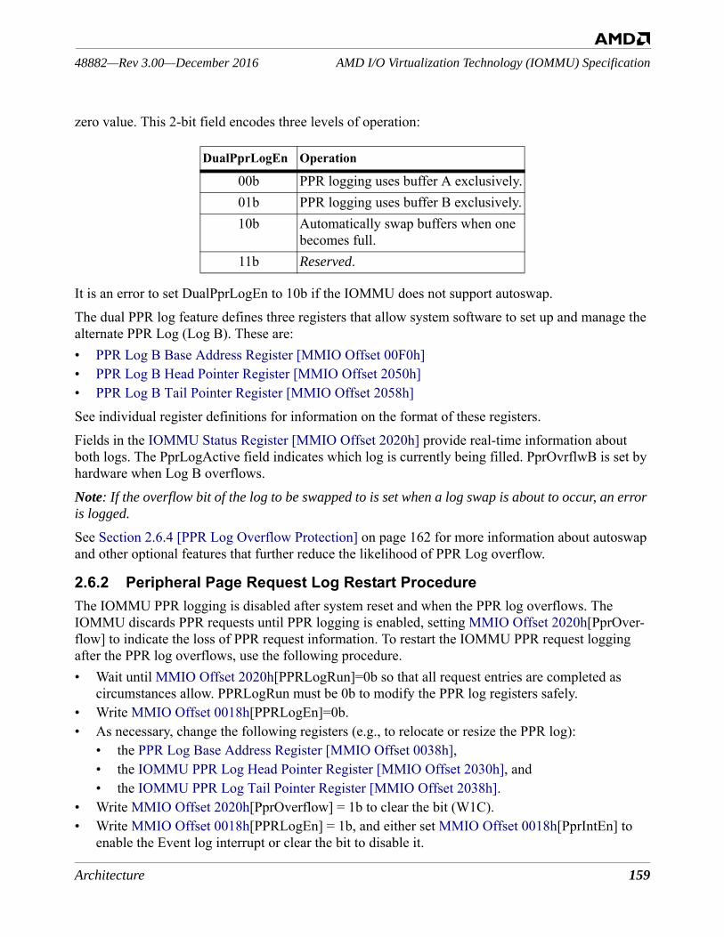
Architecture 159
AMD I/O Virtualization Technology (IOMMU) Specification48882—Rev 3.00—December 2016
zero value. This 2-bit field encodes three levels of operation:
It is an error to set DualPprLogEn to 10b if the IOMMU does not support autoswap.The dual PPR log feature defines three registers that allow system software to set up and manage the alternate PPR Log (Log B). These are:• PPR Log B Base Address Register [MMIO Offset 00F0h]• PPR Log B Head Pointer Register [MMIO Offset 2050h]• PPR Log B Tail Pointer Register [MMIO Offset 2058h]See individual register definitions for information on the format of these registers.Fields in the IOMMU Status Register [MMIO Offset 2020h] provide real-time information about both logs. The PprLogActive field indicates which log is currently being filled. PprOvrflwB is set by hardware when Log B overflows. Note: If the overflow bit of the log to be swapped to is set when a log swap is about to occur, an error is logged.
See Section 2.6.4 [PPR Log Overflow Protection] on page 162 for more information about autoswap and other optional features that further reduce the likelihood of PPR Log overflow.
2.6.2 Peripheral Page Request Log Restart ProcedureThe IOMMU PPR logging is disabled after system reset and when the PPR log overflows. The IOMMU discards PPR requests until PPR logging is enabled, setting MMIO Offset 2020h[PprOver-flow] to indicate the loss of PPR request information. To restart the IOMMU PPR request logging after the PPR log overflows, use the following procedure.• Wait until MMIO Offset 2020h[PPRLogRun]=0b so that all request entries are completed as
circumstances allow. PPRLogRun must be 0b to modify the PPR log registers safely.• Write MMIO Offset 0018h[PPRLogEn]=0b.• As necessary, change the following registers (e.g., to relocate or resize the PPR log):
• the PPR Log Base Address Register [MMIO Offset 0038h],• the IOMMU PPR Log Head Pointer Register [MMIO Offset 2030h], and • the IOMMU PPR Log Tail Pointer Register [MMIO Offset 2038h].
• Write MMIO Offset 2020h[PprOverflow] = 1b to clear the bit (W1C).• Write MMIO Offset 0018h[PPRLogEn] = 1b, and either set MMIO Offset 0018h[PprIntEn] to
enable the Event log interrupt or clear the bit to disable it.
DualPprLogEn Operation
00b PPR logging uses buffer A exclusively.01b PPR logging uses buffer B exclusively.10b Automatically swap buffers when one
becomes full.11b Reserved.
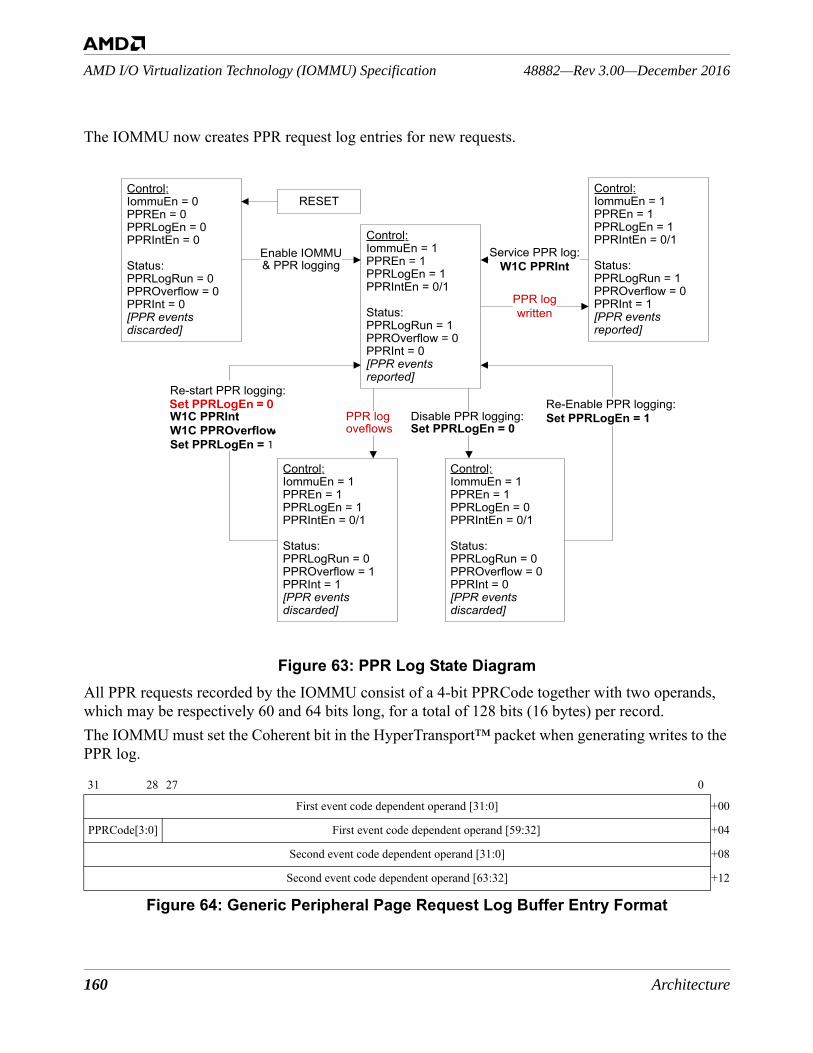
160 Architecture
48882—Rev 3.00—December 2016AMD I/O Virtualization Technology (IOMMU) Specification
The IOMMU now creates PPR request log entries for new requests.
Figure 63: PPR Log State DiagramAll PPR requests recorded by the IOMMU consist of a 4-bit PPRCode together with two operands, which may be respectively 60 and 64 bits long, for a total of 128 bits (16 bytes) per record.The IOMMU must set the Coherent bit in the HyperTransport™ packet when generating writes to the PPR log.
Figure 64: Generic Peripheral Page Request Log Buffer Entry Format
31 28 27 0
First event code dependent operand [31:0] +00
PPRCode[3:0] First event code dependent operand [59:32] +04
Second event code dependent operand [31:0] +08
Second event code dependent operand [63:32] +12
Set PPRLogEn = 0
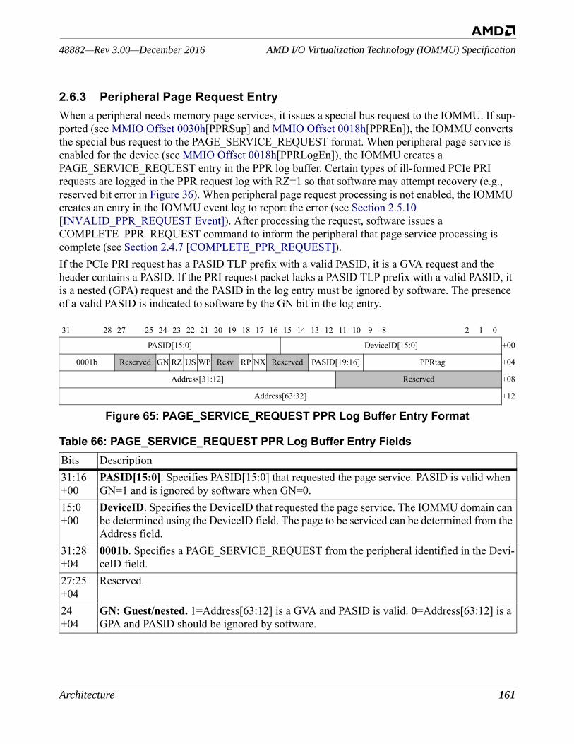
Architecture 161
AMD I/O Virtualization Technology (IOMMU) Specification48882—Rev 3.00—December 2016
2.6.3 Peripheral Page Request EntryWhen a peripheral needs memory page services, it issues a special bus request to the IOMMU. If sup-ported (see MMIO Offset 0030h[PPRSup] and MMIO Offset 0018h[PPREn]), the IOMMU converts the special bus request to the PAGE_SERVICE_REQUEST format. When peripheral page service is enabled for the device (see MMIO Offset 0018h[PPRLogEn]), the IOMMU creates a PAGE_SERVICE_REQUEST entry in the PPR log buffer. Certain types of ill-formed PCIe PRI requests are logged in the PPR request log with RZ=1 so that software may attempt recovery (e.g., reserved bit error in Figure 36). When peripheral page request processing is not enabled, the IOMMU creates an entry in the IOMMU event log to report the error (see Section 2.5.10 [INVALID_PPR_REQUEST Event]). After processing the request, software issues a COMPLETE_PPR_REQUEST command to inform the peripheral that page service processing is complete (see Section 2.4.7 [COMPLETE_PPR_REQUEST]).If the PCIe PRI request has a PASID TLP prefix with a valid PASID, it is a GVA request and the header contains a PASID. If the PRI request packet lacks a PASID TLP prefix with a valid PASID, it is a nested (GPA) request and the PASID in the log entry must be ignored by software. The presence of a valid PASID is indicated to software by the GN bit in the log entry.
Figure 65: PAGE_SERVICE_REQUEST PPR Log Buffer Entry Format
31 28 27 25 24 23 22 21 20 19 18 17 16 15 14 13 12 11 10 9 8 2 1 0
PASID[15:0] DeviceID[15:0] +00
0001b Reserved GN RZ US WP Resv RP NX Reserved PASID[19:16] PPRtag +04
Address[31:12] Reserved +08
Address[63:32] +12
Table 66: PAGE_SERVICE_REQUEST PPR Log Buffer Entry FieldsBits Description31:16 +00
PASID[15:0]. Specifies PASID[15:0] that requested the page service. PASID is valid when GN=1 and is ignored by software when GN=0.
15:0 +00
DeviceID. Specifies the DeviceID that requested the page service. The IOMMU domain can be determined using the DeviceID field. The page to be serviced can be determined from the Address field.
31:28 +04
0001b. Specifies a PAGE_SERVICE_REQUEST from the peripheral identified in the Devi-ceID field.
27:25 +04
Reserved.
24+04
GN: Guest/nested. 1=Address[63:12] is a GVA and PASID is valid. 0=Address[63:12] is a GPA and PASID should be ignored by software.
162 Architecture
48882—Rev 3.00—December 2016AMD I/O Virtualization Technology (IOMMU) Specification
The log entry is designed to carry a full set of independent read-, write-, and execute-permission bits; any bits not provided by the underlying peripheral protocol are set to the “permitted” state by the IOMMU (see also MMIO Offset 0030h[NXSup]).
2.6.4 PPR Log Overflow ProtectionThe architecture provides a number of optional features that drastically reduce the likelihood of a PPR Log overflow. These features are:• PPR Auto Response
23+04
RZ: reserved bit not zero or reserved encoding. 1=The received peripheral request had a non-zero reserved bit or used a reserved encoding. The rest of the request has been reported as it was received. Software may attempt recovery. 0=The received peripheral request passed all hardware validation checks.
22+04
US: User/Supervisor. The U/S request received from the peripheral. 1 = user level access requested. 0 = supervisor access requested.
21+04
WP: write permission requested. 1=peripheral is requesting write access. 0=write access may be denied.
20:19+04
Reserved.
18+04
RP: read permission requested. 1=peripheral is requesting read access. 0=read access may be denied.
17+04
NX: execute permission requested. 0=peripheral instruction fetch access should be han-dled as a read request. 1=peripheral is requesting NX handling of access requests (instruc-tion fetch requests will be blocked, read requests are to be allowed when RP=1).
16:14+04
Reserved.
13:10+04
PASID[19:16]. Specifies PASID[19:16] that requested the page service. PASID is valid when GN=1 and is ignored by software when GN=0.
9:0+04
PPRtag: protocol tag. This field contains a protocol-dependent tag. When the PPR request originated as a PCIe page request message, PPRtag[9] is the PRI L bit and PPRtag[8:0] is the PRI PRG index; the IOMMU is required to return the PRG index in the response message (see Section 2.4.7 [COMPLETE_PPR_REQUEST]).
31:12+08
Address[31:12]. The address field contains the DVA that the device was attempting to access. The minimum invalidation granularity is a 4-Kbyte page so the address is truncated. See also GN and PASID fields.
11:0+08
Reserved.
31:0+12
Address[63:32]. The Address field contains the DVA that the device was attempting to access. See also GN and PASID fields.
Table 66: PAGE_SERVICE_REQUEST PPR Log Buffer Entry Fields (Continued)
Architecture 163
AMD I/O Virtualization Technology (IOMMU) Specification48882—Rev 3.00—December 2016
• PPR Log Dual Buffering• PPR Auto Response Always-on• PPR Log Overflow Early Warning• Block StopMark Messages2.6.4.1 PPR Auto ResponseThe PPR auto response feature is supported when MMIO Offset 0030h[PprAutoRespSup] = 1. When enabled (by setting MMIO Offset 0018h[PprAutoRspEn] to 1), the IOMMU starts generating auto-matic PPR responses to the requesting I/O device when the currently active PPR log has reached an PPR Log at limit state.IOMMU only generates responses for peripheral page requests with the L bit set in the original request, with the exception of stop marker messages, which are dropped when there is no space in the log. All other peripheral page requests (L = 0) are dropped without any response when the log is full. When the auto response is enabled, system software does not need to manually restart PPR logging when the log has reached an at limit state. The PPR log automatically recovers regular operation when log entries are freed up. The PPR auto response feature is not available in autoswap mode (MMIO Offset 0018h[DualPprLogEn = 10b). The automatically generated PPR responses have “successful” completion code by default. This can be changed by system software, if required, by programming the PprAutoRespCode field of the PPR Log Overflow Early Indicator Register [MMIO Offset 2088h]. The PprAutoRespMskGn bit of the same register can be used to eliminate the PASID field in all the PPR auto response.Automatically generated PPR responses to PPR requests with PASID are returned with the same PASID when DTE[GPRP]=1 otherwise PPR response is returned without a PASID. Note: PPR auto response behavior is slightly different when enabled with PPR early overflow. This behavior is described below.
2.6.4.2 PPR Log Dual BufferingPPR Log dual buffering provides an alternate PPR Log (Log B) buffer space that can be programmed to capture peripheral page requests when the default PPR Log (Log A) becomes full. PPR Log dual bufferring is described in Section 2.6.1 [PPR Log Dual Buffering] on page 158.2.6.4.3 PPR Log Overflow Early IndicationThe PPR log early overflow indication feature helps prevent PPR Log overflow by providing a indi-cation to system software when the number of free entries in a PPR Log has reached a programmable threshold value. This feature is supported when MMIO Offset 0030h[PprOvrflwEarlySup] = 1. The PPR Log overflow early warning feature defines two new registers: • PPR Log Overflow Early Indicator Register [MMIO Offset 2088h] and• PPR Log B Overflow Early Indicator Register [MMIO Offset 2090h]The second register is only supported if the PPR Log dual buffering feature is supported.
164 Architecture
48882—Rev 3.00—December 2016AMD I/O Virtualization Technology (IOMMU) Specification
The first register is used to set the threshold for the overflow early warning for the default PPR Log (also known as PPR Log A when PPR log dual buffering is supported and enabled). The second reg-ister is used to set the threshold for the overflow early warning for PPR Log B.The IOMMU can be programmed to generate an MSI interrupt when the number of free entries in the PPR Log A drops below the threshold specified by MMIO Offset 2088h[PprOvrflwEarlyThreshold] or when the number of free entries in the PPR Log B drops below the threshold specified by MMIO Offset 2090h[PprOvrflwEarlyThreshold]. The PprOvrflwEarlyIntEn bit of the respective threshold registers is used to enable the interrupt.The PPR Log overflow early warning feature is not available in autoswap mode (MMIO Offset 0018h[DualPprLogEn = 10b).The PPR logger behavior is slightly different when PPR auto response and early overflow are enabled at the same time. The PPR logger generates an MSI interrupt when the number of free entries drops below the specified threshold as usual. When number of free entries in the PPR logger falls below the threshold, IOMMU begins to generated auto responses. Auto responses are generated for peripheral page requests with L bit set and the rest are silently dropped. PPR Stop marker messages are treated uniquely allowing them to be logged in the PPR Log even when the number of free entries is below the threshold, unless Stop marker messages are set to be dropped. The PPR logger resumes normal operation when system software has consumed entries from the log and the free space is more than the threshold.2.6.4.4 PPR Auto Response Always-onThe PPR auto response always-on feature builds on the auto response feature. When this feature is enabled, the IOMMU returns auto responses for peripheral page requests all the time regardless the PprOvrflwEarlyThreshold value. The feature is intended to eliminate an overflow of the PPRLOG buffer, if software cannot process it in time.The PPR auto response always-on feature is enabled when MMIO Offset 0018h[PprAutoRspAon] = 1. This feature requires that PPR Auto Response also be enabled. This feature should be turned on (along with PPR auto response) whenever system software is dynamically relocating or resizing the log.The PPR auto response always-on feature is supported on all implementations that support the PPR auto response feature.2.6.4.5 Block StopMark MessagesThe Block StopMark Messages feature provides the capability for the IOMMU to silently drop all the stop marker messages without error. This feature includes an internal performance event counter to count the number of stop marker messages that have been discarded since the counter was reset.This feature is supported if MMIO Offset 0030h[BlkStopMrkSup] = 1. If supported, this feature is enabled by default. To disable the feature, MMIO Offset 0018h[BlkStopMrkEn] should be set to 0.
2.7 Guest Virtual APIC (GA) LoggingAn IOMMU that supports the guest virtual APIC feature (MMIO Offset 0030h[GASup] = 1) can
Architecture 165
AMD I/O Virtualization Technology (IOMMU) Specification48882—Rev 3.00—December 2016
deliver interrupts directly to a running guest operating system in a virtual machine when used with an AMD processor that supports the Advanced Virtual Interrupt Controller (AVIC) architecture. This architecture defines the behavior and the system programming interface for the guest virtual APIC (vAPIC). See the full description of AVIC in Chapter 15 of AMD64 Architecture Programmer’s Man-ual, Volume 2: System Programming, order #24593.Guest vAPIC logging is used to record device interrupt requests that could not be immediately deliv-ered to the target virtual processor due the fact the target was not running. When logging is enabled and an interrupt request for a non-running virtual processor arrives from an I/O device, the IOMMU creates an entry in the GALog. This entry records the Device ID of the requesting device and the GATag of the target vAPIC. System software supplies the GATag by writing it in the appropriate IRTE of the Interrupt Remap Table for the device.
2.7.1 Guest vAPIC Virtual Interrupt Request LogThe guest vAPIC virtual interrupt request log (GA Log) is diagrammed in Figure 66 below.
Figure 66: Guest vAPIC Log in System MemoryThe GA Log is circular buffer in system physical memory that provides a queue of virtual interrupt requests waiting to be delivered to their target virtual processors. These virtual interrupt requests could not be delivered immediately due to the non-running state of the target virtual processor. Log entries identify the source of the virtual interrupt request and the target virtual processor. The source is identified using the Device ID of the device initiating the interrupt request. The target is recorded using the GATag value assigned by system software.When the IOMMU receives a virtual interrupt request from an I/O device it records the request by
Guest vAPIC Log entry
GALog Tail (copy)
Guest vAPIC Log entry
+0
+8
+ LogLen − 16
+ LogLen − 8
+ LogLen − 24
+ LogLen − 40
+ LogLen − 48
GALogHead
GALogBase
GALogTail
GATAddr
log base address
log size
head pointer
tail pointer address
SPA
SPA
(Offset)
(Offset)
(Offset)
IOMMU Registers Software Variables
IOMMU logs virtual interrupt requests (when IsRun = 0)
IOMMU writes new log entries at tail pointer
Software reads log entries at head pointer
System Memory
+ LogLen − 32
IOMMU updates copy in memory
166 Architecture
48882—Rev 3.00—December 2016AMD I/O Virtualization Technology (IOMMU) Specification
updating the appropriate IRR bit of vAPIC backing page of the vAPIC associated with the target vir-tual processor. If the target virtual processor is running at the time of the interrupt request, the IOMMU completes the delivery of the interrupt by sending a doorbell interrupt to the physical pro-cessor that is hosting the virtual processor.If the target virtual processor is not running, delivery of the interrupt must be deferred. Instead of causing a doorbell interrupt, the IOMMU logs the details of the request in the GA Log. The virtual interrupt remains pending until system software makes the targeted virtual processor active. When the virtual processor is again active it acts on the interrupt request that the IOMMU has already set in the IRR of the vAPIC backing page. System software utilizes information logged in the GALog to make virtual processor scheduling decisions.Guest virtual APIC event logging is enabled when MMIO Offset 0018h[GAEn] = 1, MMIO Offset 2020h[GALogRun] = 1, and IRTE[GALogIntr] = 1 (see Figure 18). The IRTE[IsRun] field indicates whether or not the target virtual processor is running.
Figure 67: Guest Virtual APIC Log State DiagramWhen logging a virtual interrupt request in the GA Log, the IOMMU writes the next available GA Log entry. Assuming the log is not full, this is the entry pointed to by the GA Log tail pointer (MMIO
1
Set GALogEn = 0
Architecture 167
AMD I/O Virtualization Technology (IOMMU) Specification48882—Rev 3.00—December 2016
Offset 2048h[GALogTail]). After writing the new log entry, the IOMMU advances the GA Log tail pointer and sets the MMIO Offset 2020h[GAInt] bit. If enabled via MMIO Offset 0018h[GAIntEn] = 1, the setting of the GAInt bit generates an message signalled interrupt using the MSI number speci-fied by Capability Offset 14h[MsiNumGA].To find the next entry to be processed, system software reads the GALog entry at the location pointed to by the GA Log head pointer and advances the head pointer to indicate that it has consumed the entry. After it advances the head pointer, it compares the new value of the head pointer to the current value of the tail pointer. (The IOMMU maintains a copy of its GA Log tail pointer in system memory at the system physical memory location pointed to by MMIO Offset 00E8h.) If the new value of the head pointer is equal to the tail pointer, there are no more entries in the log for system software to consume. If the head and tail pointers are not equal, this indicates that there are more entries in the GA Log.When done processing one or more GA Log entries, system software writes the new value of the head pointer to the IOMMU head pointer register (MMIO Offset 2040h) to indicate to the IOMMU that the consumed entries in the GA Log have been freed up. The IOMMU uses this value to determine if the log is full. The GA Log is considered full if the tail pointer is pointing at the entry immediately below the head pointer. Note that since the buffer is circular that “below” does not always mean at a numer-ically smaller offset. Since the tail pointer always points at the entry to be written next, the last entry (the one immediately below the head) in the circular buffer always remains unused. If the log is full at the time of the arrival of the virtual interrupt request, logging is suspended and MMIO Offset 2020h[GALOverflow] is set to 1. When this occurs software must intervene to resume logging.Note that the IOMMU maintains a copy of the tail pointer register (MMIO Offset 2048h) in system memory at the location specified by the contents of the register MMIO Offset 00E8h to reduce the latency involved in reading the current value of the tail pointer from the internal register. The Guest Virtual APIC Log Base Address Register [MMIO Offset 00E0h] is used by system soft-ware to assign the system physical address of the guest vAPIC log and to define its size. The guest vAPIC log occupies contiguous physical memory starting at the programmed base address up to the programmed size. The size of the guest virtual APIC log must be a multiple of 4 Kbytes (to facilitate “modulo N” indexing for circularity) and can be as large as 8192 entries (corresponding to a 64-Kbyte buffer). The base address of the GA log must be aligned to a multiple of 4 Kbytes.System software uses the Guest Virtual APIC Log Tail Address Register [MMIO Offset 00E8h] to assign the system physical address of the location where IOMMU maintains the copy of the guest vAPIC Log tail pointer. Software is responsible to initialize the head and tail pointers to zero to create an empty log before enabling guest vAPIC event logging. When the head pointer and the tail pointer are equal, the guest virtual APIC event log is empty. To add an entry to the guest virtual APIC log, the IOMMU proceeds as follows:1. Compare the GA Log head and tail pointers (MMIO Offset 2040h[GALogHead] and MMIO Off-
set 2048h[GALogTail]) to determine if the log is full.
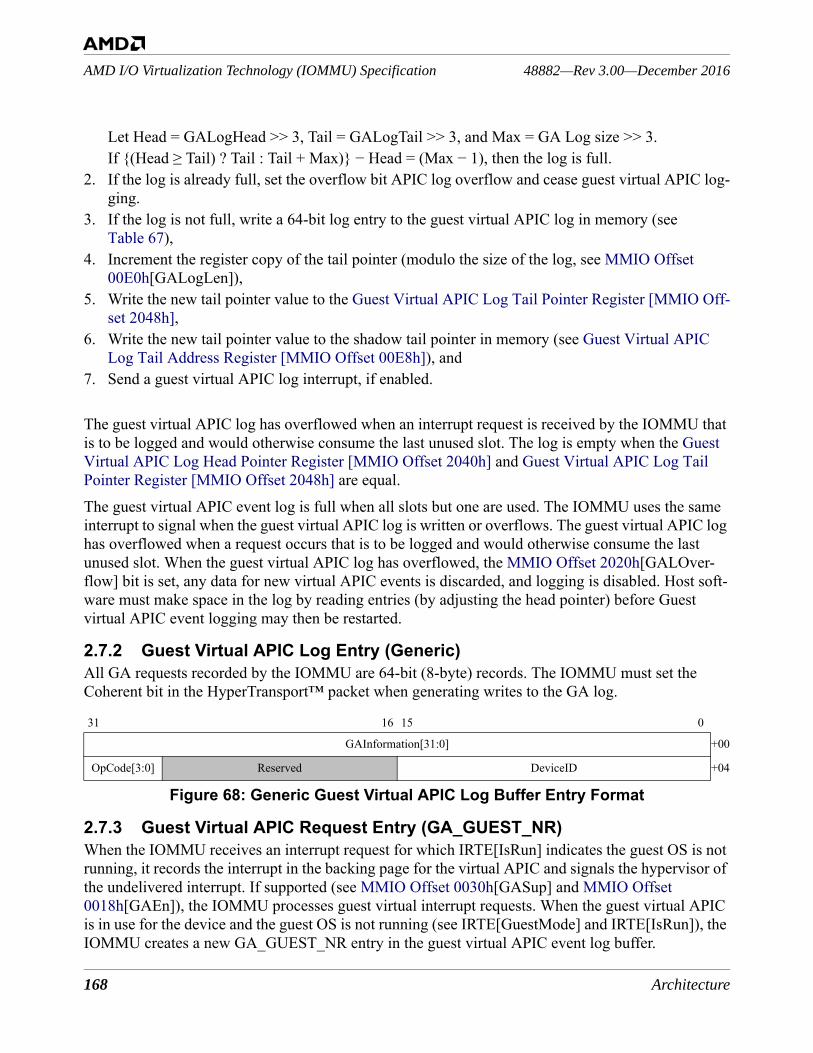
168 Architecture
48882—Rev 3.00—December 2016AMD I/O Virtualization Technology (IOMMU) Specification
Let Head = GALogHead >> 3, Tail = GALogTail >> 3, and Max = GA Log size >> 3.If {(Head ≥ Tail) ? Tail : Tail + Max)} − Head = (Max − 1), then the log is full.
2. If the log is already full, set the overflow bit APIC log overflow and cease guest virtual APIC log-ging.
3. If the log is not full, write a 64-bit log entry to the guest virtual APIC log in memory (see Table 67),
4. Increment the register copy of the tail pointer (modulo the size of the log, see MMIO Offset 00E0h[GALogLen]),
5. Write the new tail pointer value to the Guest Virtual APIC Log Tail Pointer Register [MMIO Off-set 2048h],
6. Write the new tail pointer value to the shadow tail pointer in memory (see Guest Virtual APIC Log Tail Address Register [MMIO Offset 00E8h]), and
7. Send a guest virtual APIC log interrupt, if enabled.
The guest virtual APIC log has overflowed when an interrupt request is received by the IOMMU that is to be logged and would otherwise consume the last unused slot. The log is empty when the Guest Virtual APIC Log Head Pointer Register [MMIO Offset 2040h] and Guest Virtual APIC Log Tail Pointer Register [MMIO Offset 2048h] are equal.The guest virtual APIC event log is full when all slots but one are used. The IOMMU uses the same interrupt to signal when the guest virtual APIC log is written or overflows. The guest virtual APIC log has overflowed when a request occurs that is to be logged and would otherwise consume the last unused slot. When the guest virtual APIC log has overflowed, the MMIO Offset 2020h[GALOver-flow] bit is set, any data for new virtual APIC events is discarded, and logging is disabled. Host soft-ware must make space in the log by reading entries (by adjusting the head pointer) before Guest virtual APIC event logging may then be restarted.
2.7.2 Guest Virtual APIC Log Entry (Generic)All GA requests recorded by the IOMMU are 64-bit (8-byte) records. The IOMMU must set the Coherent bit in the HyperTransport™ packet when generating writes to the GA log.
Figure 68: Generic Guest Virtual APIC Log Buffer Entry Format
2.7.3 Guest Virtual APIC Request Entry (GA_GUEST_NR)When the IOMMU receives an interrupt request for which IRTE[IsRun] indicates the guest OS is not running, it records the interrupt in the backing page for the virtual APIC and signals the hypervisor of the undelivered interrupt. If supported (see MMIO Offset 0030h[GASup] and MMIO Offset 0018h[GAEn]), the IOMMU processes guest virtual interrupt requests. When the guest virtual APIC is in use for the device and the guest OS is not running (see IRTE[GuestMode] and IRTE[IsRun]), the IOMMU creates a new GA_GUEST_NR entry in the guest virtual APIC event log buffer.
31 16 15 0
GAInformation[31:0] +00
OpCode[3:0] Reserved DeviceID +04

Architecture 169
AMD I/O Virtualization Technology (IOMMU) Specification48882—Rev 3.00—December 2016
Figure 69: GA_GUEST_NR Log Buffer Entry Format
The log entry contains a GATag field for software use.
2.7.4 Guest Virtual APIC Log Restart ProcedureThe IOMMU guest virtual APIC logging is disabled after system reset and when the log overflows. The IOMMU does not log guest virtual APIC events until logging is enabled, setting IOMMU Status Register [MMIO Offset 2020h][GALOverflow] to indicate that guest APIC events are not being logged. To restart the guest virtual APIC event logging after the log overflows, use the following pro-cedure.• Wait until MMIO Offset 2020h[GALogRun]=0b so that all request entries are completed as
circumstances allow. GALogRun must be 0b to modify the guest virtual APIC log registers safely.• Write MMIO Offset 0018h[GALogEn]=0b.• As necessary, change the following values (e.g., to relocate or resize the guest virtual APIC event
log):• the Guest Virtual APIC Log Base Address Register [MMIO Offset 00E0h],• the Guest Virtual APIC Log Head Pointer Register [MMIO Offset 2040h][GALogHead], and • the Guest Virtual APIC Log Tail Pointer Register [MMIO Offset 2048h][GALogTail].
• Write MMIO Offset 2020h[GALOverflow] = 1b to clear the bit (W1C).• Write MMIO Offset 0018h[GALogEn] = 1b, and either set MMIO Offset 0018h[GAIntEn] to
enable the GA log interrupt or clear the bit to disable it.
The IOMMU now creates guest virtual APIC event log entries for new events.
31 28 27 16 15 8 0
GATag +00
0001b Reserved DeviceID +04
Table 67: GA_GUEST_NR Log Buffer Entry FieldsBits Description31:0 +00
GATag[31:0]. Specifies the GATag taken from the IRTE entry (see Figure 18 and Table 22) that requested the virtual interrupt service for the guest found to be not-running.
31:28 +04
0001b. Specifies a GA_GUEST_NR from the peripheral identified in the DeviceID field.
27:16 +04
Reserved.
15:0+04
DeviceID. Specifies the DeviceID that requested the guest virtual interrupt service.
170 Architecture
48882—Rev 3.00—December 2016AMD I/O Virtualization Technology (IOMMU) Specification
2.8 IOMMU Interrupt SupportThe IOMMU supports the signaling of interrupts using both the MSI and the MSI-X mechanisms. However, only one mechanism can be enabled at a time. The MSI capability must support 64-bit addressing. The IOMMU must not set the PassPW bit when sending interrupts associated with the IOMMU over HyperTransport™ links.The IOMMU supports generation of an interrupt when the event log is updated or overflows and when a completion wait command completes (see Capability Offset 10h[MsiNum], MMIO Offset 0018h[ComWaitEn], and MMIO Offset 0018h[EventIntEn]), and when the peripheral page request log is updated or overflows (see Capability Offset 10h[MsiNumPPR] and MMIO Offset 0018h[PprIntEn]).
2.9 Memory Address Routing and Control (MARC)The Memory Access Routing and Control (MARC) feature provides simple, static memory virtual-ization and access protection for SoC-integrated devices that require low-latency access to system memory. MARC provides this address virtualization while avoiding the need for costly page table walks. MARC hardware is set up and controlled by trusted system software.When a device virtual address (DVA) lies within one of the defined regions (MARC aperture) and access permissions checking allows the access requested by the device, the IOMMU translation mechanism is bypassed and MARC provides the system physical address to be used for the access. If the DVA does not lie within one of the programmed and enabled apertures, or the access is denied based on permissions checking, the address is passed to the IOMMU without flagging an error. The IOMMU will then use the translation and permissions information in its page tables to check the access. If a translation is available and permissions checking allows the access, the IOMMU will complete the translation.Each MARC aperture is defined by programming a base and a length register. For each aperture, a third relocation register provides the system physical address (SPA) to which that region in the DVA space is mapped. Access protection and an enable bit are provided by fields in the relocation register. The mechanism maps aligned 4-Kbyte pages of address space.A given implementation may support either four or eight MARC apertures. MMIO Offset 0030h[MarcSup] supplies the number of MARC apertures supported by a given implementation. MMIO Offset 0018h[MarcEn] provides a global enable for the MARC feature. If MarcEn is set to 0, all DVAs emitted by I/O devices are sent to the IOMMU for translation.The relocation register for each aperture MARC Aperture [0–3] Relocation Register [MMIO Offset 02[08,20,38,50]h] provides a RelocEn bit to enable each individual aperture 0–3 and a ReadOnly bit to establish the device access allowed for each aperture. When ReadOnly is programmed to 0, device read or write access is allowed; when programmed to 1, only read access is allowed. When RelocEn is set to 0, the corresponding aperture is ignored.The MARC mechanism maps addresses at a 4-Kbyte granularity. The architecture supports 52-bit addresses. Thus only address bits [51:12] of the DVA are examined. Interpreted as an unsigned inte-ger, this corresponds the page frame number (PFN).
Architecture 171
AMD I/O Virtualization Technology (IOMMU) Specification48882—Rev 3.00—December 2016
The PFN of the DVA is compared with the PFN specified by the value of bits [51:12] of the MARC Aperture [0–3] Base Register [MMIO Offset 02[00,18,30,48]h]. If the difference is greater than or equal to zero but less than MarcLength specified by bits [51:12] of the MARC Aperture [0–3] Length Register [MMIO Offset 02[10,28,40,58]h], the DVA falls within the corresponding MARC aperture and the access permission for that aperture is checked. If requested access type (read or write) is allowed by the setting of ReadOnly for that aperture, the access is allowed and bits [51:12] of the relocation register are substituted for bits [51:12] of the DVA. The byte offset within the page is pro-vided by bits [11:0] of the DVA.To define an aperture of one 4-Kbyte page, MarcLength is programmed to 1. If a value of 0 is used, the behavior of the hardware is implementation-dependent, but does not result in an error.

172 Architecture
48882—Rev 3.00—December 2016AMD I/O Virtualization Technology (IOMMU) Specification
Registers 173
AMD I/O Virtualization Technology (IOMMU) Specification48882—Rev 3.00—December 2016
3 Registers
The IOMMU is configured and controlled via two sets of registers—one in the PCI configuration space and another set mapped in system address space. Since the IOMMU appears as a PCI function, it has a capability block in the PCI configuration space. IOMMU registers not defined in this chapter are reserved. Software should not write reserved register locations and must not rely on the value returned by hardware if a reserved register is read. Bit ranges within writeable registers that are designated as Reserved should always be written as all zeros. When read, software must not rely on the value returned in that bit range.
3.1 PCI ResourcesThe IOMMU is implemented as an independent PCI Function. Any PCI Function containing an IOMMU capability block cannot be used for any purpose other than containing an IOMMU. A PCI Function containing an IOMMU capability block does not include PCI BAR registers. Configuration and status information for the IOMMU are mapped into PCI configuration space using a PCI capabil-ity block. A peripheral may implement more than one IOMMU within a single Function. One or more IOMMU capability blocks may be implemented in a PCIe® Function.If a single IOMMU capability block is implemented in a PCI Function, the IOMMU may support either MSI or MSI-X or both. If more than one IOMMU capability block is implemented in a Func-tion, the IOMMU must support generating MSI-X interrupts. The Function must assign a distinct interrupt vector to each interrupt that can be generated by each IOMMU capability block. The base functionality of the IOMMU supports one interrupt which is used report Event Log excep-tions and CommWait Completions. If this interrupt is enabled, the field Capability Offset 10h[Msi-Num] must be written with the appropriate MSI/MSI-X vector. If PPR logging and GA logging are supported, two more interrupt sources are provided to signal PPR and GA logging exceptions. If the PPR log interrupt is to be enabled, a vector for it must be first set up for it in Capability Offset 10h[MsiNumPPR]. If the GA log interrupt is to be enabled, a vector for it must be first set up in Capa-bility Offset 10h[MsiNumGA]. The PCI class is System Base Peripheral (08h) with a subclass of IOMMU (06h) and a programming interface code of 00h, as issued by the PCI-SIG.The HyperTransport™ UnitID used when an IOMMU generates requests must not be used for any other traffic. A HyperTransport™ UnitID can be shared by multiple IOMMUs within a physical com-ponent.
3.1.1 Accessing MSI Capability Block RegistersOptionally, specific fields of the MSI capability registers are mapped to MMIO space by IOMMU hardware. When this capability is supported these registers can be accessed either through configura-tion space reads and writes or via memory reads and writes. However, in some cases field write capa-
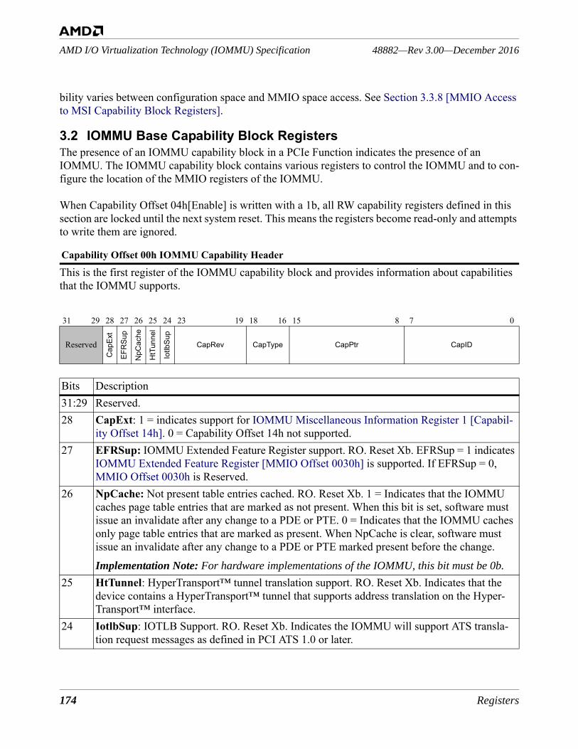
174 Registers
48882—Rev 3.00—December 2016AMD I/O Virtualization Technology (IOMMU) Specification
bility varies between configuration space and MMIO space access. See Section 3.3.8 [MMIO Access to MSI Capability Block Registers].
3.2 IOMMU Base Capability Block RegistersThe presence of an IOMMU capability block in a PCIe Function indicates the presence of an IOMMU. The IOMMU capability block contains various registers to control the IOMMU and to con-figure the location of the MMIO registers of the IOMMU.
When Capability Offset 04h[Enable] is written with a 1b, all RW capability registers defined in this section are locked until the next system reset. This means the registers become read-only and attempts to write them are ignored.
This is the first register of the IOMMU capability block and provides information about capabilities that the IOMMU supports.
Capability Offset 00h IOMMU Capability Header
31 29 28 27 26 25 24 23 19 18 16 15 8 7 0
Reserved
Cap
Ext
EFR
Sup
NpC
ache
HtT
unne
l
Iotlb
Sup
CapRev CapType CapPtr CapID
Bits Description31:29 Reserved.28 CapExt: 1 = indicates support for IOMMU Miscellaneous Information Register 1 [Capabil-
ity Offset 14h]. 0 = Capability Offset 14h not supported.27 EFRSup: IOMMU Extended Feature Register support. RO. Reset Xb. EFRSup = 1 indicates
IOMMU Extended Feature Register [MMIO Offset 0030h] is supported. If EFRSup = 0, MMIO Offset 0030h is Reserved.
26 NpCache: Not present table entries cached. RO. Reset Xb. 1 = Indicates that the IOMMU caches page table entries that are marked as not present. When this bit is set, software must issue an invalidate after any change to a PDE or PTE. 0 = Indicates that the IOMMU caches only page table entries that are marked as present. When NpCache is clear, software must issue an invalidate after any change to a PDE or PTE marked present before the change.Implementation Note: For hardware implementations of the IOMMU, this bit must be 0b.
25 HtTunnel: HyperTransport™ tunnel translation support. RO. Reset Xb. Indicates that the device contains a HyperTransport™ tunnel that supports address translation on the Hyper-Transport™ interface.
24 IotlbSup: IOTLB Support. RO. Reset Xb. Indicates the IOMMU will support ATS transla-tion request messages as defined in PCI ATS 1.0 or later.
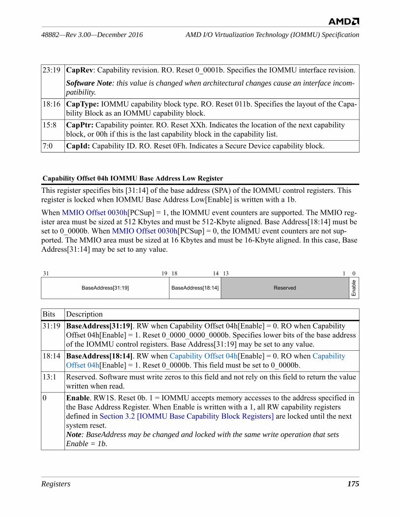
Registers 175
AMD I/O Virtualization Technology (IOMMU) Specification48882—Rev 3.00—December 2016
This register specifies bits [31:14] of the base address (SPA) of the IOMMU control registers. This register is locked when IOMMU Base Address Low[Enable] is written with a 1b. When MMIO Offset 0030h[PCSup] = 1, the IOMMU event counters are supported. The MMIO reg-ister area must be sized at 512 Kbytes and must be 512-Kbyte aligned. Base Address[18:14] must be set to 0_0000b. When MMIO Offset 0030h[PCSup] = 0, the IOMMU event counters are not sup-ported. The MMIO area must be sized at 16 Kbytes and must be 16-Kbyte aligned. In this case, Base Address[31:14] may be set to any value.
23:19 CapRev: Capability revision. RO. Reset 0_0001b. Specifies the IOMMU interface revision. Software Note: this value is changed when architectural changes cause an interface incom-patibility.
18:16 CapType: IOMMU capability block type. RO. Reset 011b. Specifies the layout of the Capa-bility Block as an IOMMU capability block.
15:8 CapPtr: Capability pointer. RO. Reset XXh. Indicates the location of the next capability block, or 00h if this is the last capability block in the capability list.
7:0 CapId: Capability ID. RO. Reset 0Fh. Indicates a Secure Device capability block.
Capability Offset 04h IOMMU Base Address Low Register
31 19 18 14 13 1 0
BaseAddress[31:19] BaseAddress[18:14] Reserved
Enab
le
Bits Description31:19 BaseAddress[31:19]. RW when Capability Offset 04h[Enable] = 0. RO when Capability
Offset 04h[Enable] = 1. Reset 0_0000_0000_0000b. Specifies lower bits of the base address of the IOMMU control registers. Base Address[31:19] may be set to any value.
18:14 BaseAddress[18:14]. RW when Capability Offset 04h[Enable] = 0. RO when CapabilityOffset 04h[Enable] = 1. Reset 0_0000b. This field must be set to 0_0000b.
13:1 Reserved. Software must write zeros to this field and not rely on this field to return the value written when read.
0 Enable. RW1S. Reset 0b. 1 = IOMMU accepts memory accesses to the address specified in the Base Address Register. When Enable is written with a 1, all RW capability registers defined in Section 3.2 [IOMMU Base Capability Block Registers] are locked until the next system reset. Note: BaseAddress may be changed and locked with the same write operation that sets Enable = 1b.
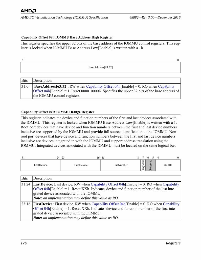
176 Registers
48882—Rev 3.00—December 2016AMD I/O Virtualization Technology (IOMMU) Specification
This register specifies the upper 32 bits of the base address of the IOMMU control registers. This reg-ister is locked when IOMMU Base Address Low[Enable] is written with a 1b.
This register indicates the device and function numbers of the first and last devices associated with the IOMMU. This register is locked when IOMMU Base Address Low[Enable] is written with a 1. Root port devices that have device and function numbers between the first and last device numbers inclusive are supported by the IOMMU and provide full source identification to the IOMMU. Non-root port devices that have device and function numbers between the first and last device numbers inclusive are devices integrated in with the IOMMU and support address translation using the IOMMU. Integrated devices associated with the IOMMU must be located on the same logical bus.
Capability Offset 08h IOMMU Base Address High Register
31 0
BaseAddress[63:32]
Bits Description31:0 BaseAddress[63:32]. RW when Capability Offset 04h[Enable] = 0. RO when Capability
Offset 04h[Enable] = 1. Reset 0000_0000h. Specifies the upper 32 bits of the base address of the IOMMU control registers.
Capability Offset 0Ch IOMMU Range Register
31 24 23 16 15 8 7 6 5 4 0
LastDevice FirstDevice BusNumber
RngV
alid
Rese
rved
UnitID
Bits Description31:24 LastDevice: Last device. RW when Capability Offset 04h[Enable] = 0. RO when Capability
Offset 04h[Enable] = 1. Reset XXh. Indicates device and function number of the last inte-grated device associated with the IOMMU. Note: an implementation may define this value as RO.
23:16 FirstDevice: First device. RW when Capability Offset 04h[Enable] = 0. RO when Capability Offset 04h[Enable] = 1. Reset XXh. Indicates device and function number of the first inte-grated device associated with the IOMMU. Note: an implementation may define this value as RO.
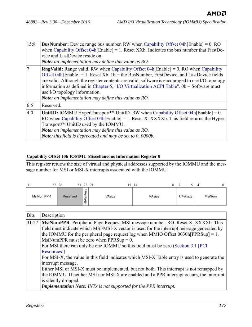
Registers 177
AMD I/O Virtualization Technology (IOMMU) Specification48882—Rev 3.00—December 2016
This register returns the size of virtual and physical addresses supported by the IOMMU and the mes-sage number for MSI or MSI-X interrupts associated with the IOMMU.
15:8 BusNumber: Device range bus number. RW when Capability Offset 04h[Enable] = 0. RO when Capability Offset 04h[Enable] = 1. Reset XXh. Indicates the bus number that FirstDe-vice and LastDevice reside on.Note: an implementation may define this value as RO.
7 RngValid: Range valid. RW when Capability Offset 04h[Enable] = 0. RO when Capability Offset 04h[Enable] = 1. Reset Xb. 1b = the BusNumber, FirstDevice, and LastDevice fields are valid. Although the register contents are valid, software is encouraged to use I/O topology information as defined in Chapter 5, "I/O Virtualization ACPI Table". 0b = Software must use I/O topology information.Note: an implementation may define this value as RO.
6:5 Reserved.4:0 UnitID: IOMMU HyperTransport™ UnitID. RW when Capability Offset 04h[Enable] = 0.
RO when Capability Offset 04h[Enable] = 1. Reset X_XXXXb. This field returns the Hyper-Transport™ UnitID used by the IOMMU. Note: an implementation may define this value as RO.Note: this field is deprecated and may be set to 0_0000b.
Capability Offset 10h IOMMU Miscellaneous Information Register 0
31 27 26 23 22 21 15 14 8 7 5 4 0
MsiNumPPR Reserved
HtA
tsR
esv
VAsize PAsize GVAsize MsiNum
Bits Description31:27 MsiNumPPR: Peripheral Page Request MSI message number. RO. Reset X_XXXXb. This
field must indicate which MSI/MSI-X vector is used for the interrupt message generated by the IOMMU for the peripheral page request log when MMIO Offset 0030h[PPRSup] = 1. MsiNumPPR must be zero when PPRSup = 0.For MSI there can only be one IOMMU so this field must be zero (Section 3.1 [PCI Resources]).For MSI-X, the value in this field indicates which MSI-X Table entry is used to generate the interrupt message.Either MSI or MSI-X must be implemented, but not both. This interrupt is not remapped by the IOMMU. If neither MSI nor MSI-X are enabled and a PPR interrupt occurs, the interrupt is silently dropped.Implementation Note: INTx is not supported for the PPR interrupt.
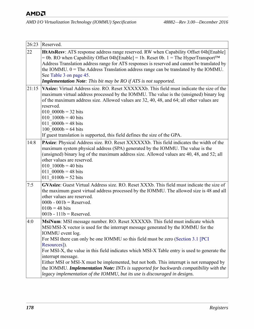
178 Registers
48882—Rev 3.00—December 2016AMD I/O Virtualization Technology (IOMMU) Specification
26:23 Reserved.22 HtAtsResv: ATS response address range reserved. RW when Capability Offset 04h[Enable]
= 0b. RO when Capability Offset 04h[Enable] = 1b. Reset 0b. 1 = The HyperTransport™ Address Translation address range for ATS responses is reserved and cannot be translated by the IOMMU. 0 = The Address Translation address range can be translated by the IOMMU. See Table 3 on page 45. Implementation Note: This bit may be RO if ATS is not supported.
21:15 VAsize: Virtual Address size. RO. Reset XXXXXXb. This field must indicate the size of the maximum virtual address processed by the IOMMU. The value is the (unsigned) binary log of the maximum address size. Allowed values are 32, 40, 48, and 64; all other values are reserved.010_0000b = 32 bits010_1000b = 40 bits011_0000b = 48 bits100_0000b = 64 bitsIf guest translation is supported, this field defines the size of the GPA.
14:8 PAsize: Physical Address size. RO. Reset XXXXXXb. This field indicates the width of the maximum system physical address (SPA) generated by the IOMMU. The value is the (unsigned) binary log of the maximum address size. Allowed values are 40, 48, and 52; all other values are reserved.010_1000b = 40 bits011_0000b = 48 bits011_0100b = 52 bits
7:5 GVAsize: Guest Virtual Address size. RO. Reset XXXb. This field must indicate the size of the maximum guest virtual address processed by the IOMMU. The allowed size is 48 and all other values are reserved.000b - 001b = Reserved.010b = 48 bits001b - 111b = Reserved.
4:0 MsiNum: MSI message number. RO. Reset XXXXXb. This field must indicate which MSI/MSI-X vector is used for the interrupt message generated by the IOMMU for the IOMMU event log.For MSI there can only be one IOMMU so this field must be zero (Section 3.1 [PCI Resources]).For MSI-X, the value in this field indicates which MSI-X Table entry is used to generate the interrupt message.Either MSI or MSI-X must be implemented, but not both. This interrupt is not remapped by the IOMMU. Implementation Note: INTx is supported for backwards compatibility with the legacy implementation of the IOMMU, but its use is discouraged in designs.
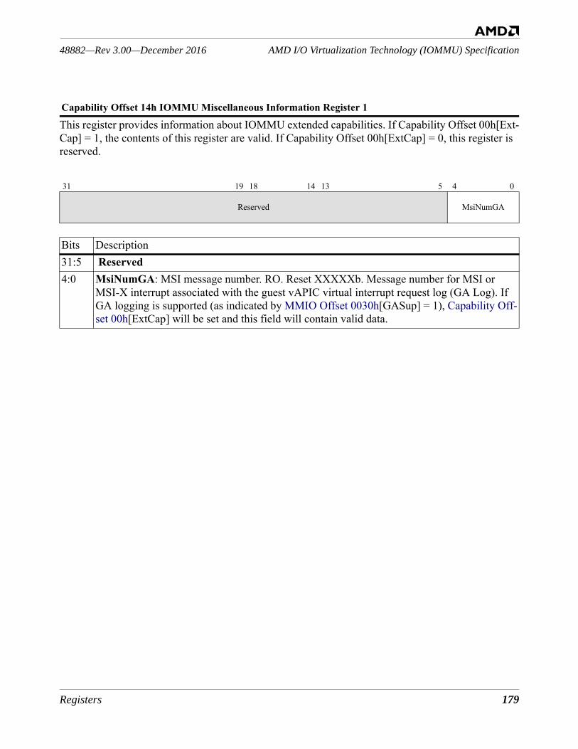
Registers 179
AMD I/O Virtualization Technology (IOMMU) Specification48882—Rev 3.00—December 2016
This register provides information about IOMMU extended capabilities. If Capability Offset 00h[Ext-Cap] = 1, the contents of this register are valid. If Capability Offset 00h[ExtCap] = 0, this register is reserved.
Capability Offset 14h IOMMU Miscellaneous Information Register 1
31 19 18 14 13 5 4 0
Reserved MsiNumGA
Bits Description31:5 Reserved4:0 MsiNumGA: MSI message number. RO. Reset XXXXXb. Message number for MSI or
MSI-X interrupt associated with the guest vAPIC virtual interrupt request log (GA Log). If GA logging is supported (as indicated by MMIO Offset 0030h[GASup] = 1), Capability Off-set 00h[ExtCap] will be set and this field will contain valid data.
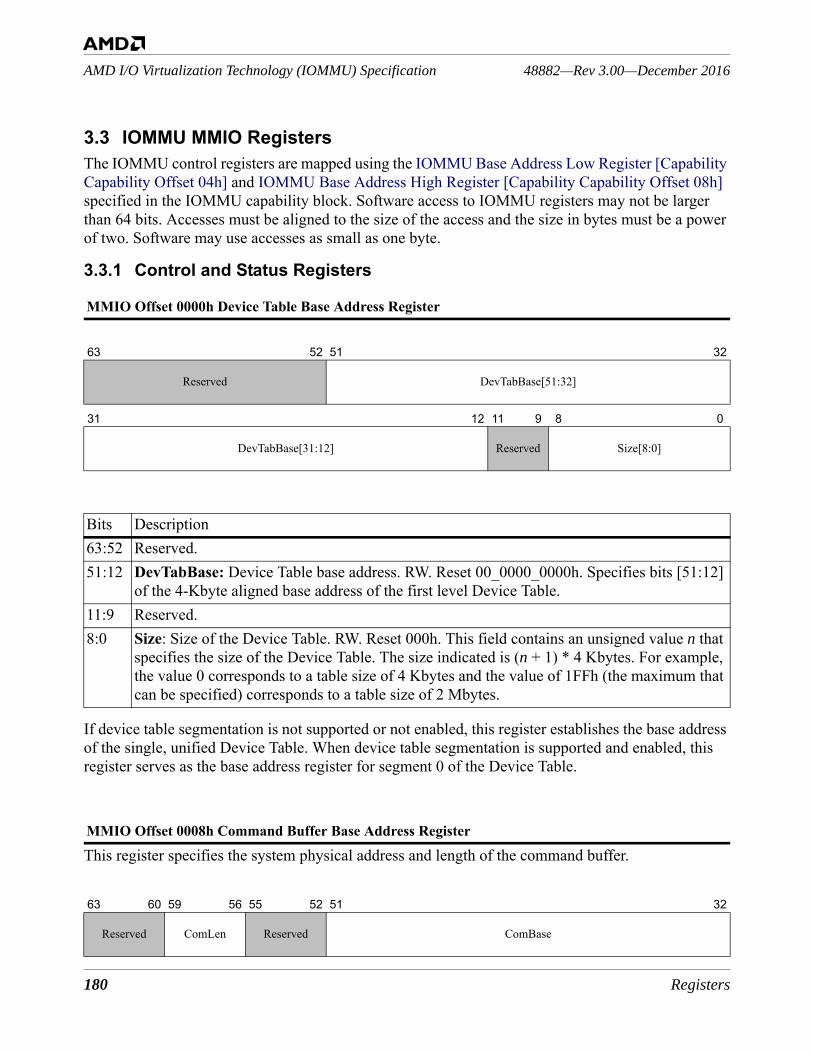
180 Registers
48882—Rev 3.00—December 2016AMD I/O Virtualization Technology (IOMMU) Specification
3.3 IOMMU MMIO RegistersThe IOMMU control registers are mapped using the IOMMU Base Address Low Register [Capability Capability Offset 04h] and IOMMU Base Address High Register [Capability Capability Offset 08h] specified in the IOMMU capability block. Software access to IOMMU registers may not be larger than 64 bits. Accesses must be aligned to the size of the access and the size in bytes must be a power of two. Software may use accesses as small as one byte.
3.3.1 Control and Status Registers
If device table segmentation is not supported or not enabled, this register establishes the base address of the single, unified Device Table. When device table segmentation is supported and enabled, this register serves as the base address register for segment 0 of the Device Table.
This register specifies the system physical address and length of the command buffer.
MMIO Offset 0000h Device Table Base Address Register
63 52 51 32
Reserved DevTabBase[51:32]
31 12 11 9 8 0
DevTabBase[31:12] Reserved Size[8:0]
Bits Description63:52 Reserved. 51:12 DevTabBase: Device Table base address. RW. Reset 00_0000_0000h. Specifies bits [51:12]
of the 4-Kbyte aligned base address of the first level Device Table.11:9 Reserved.8:0 Size: Size of the Device Table. RW. Reset 000h. This field contains an unsigned value n that
specifies the size of the Device Table. The size indicated is (n + 1) * 4 Kbytes. For example, the value 0 corresponds to a table size of 4 Kbytes and the value of 1FFh (the maximum that can be specified) corresponds to a table size of 2 Mbytes.
MMIO Offset 0008h Command Buffer Base Address Register
63 60 59 56 55 52 51 32
Reserved ComLen Reserved ComBase
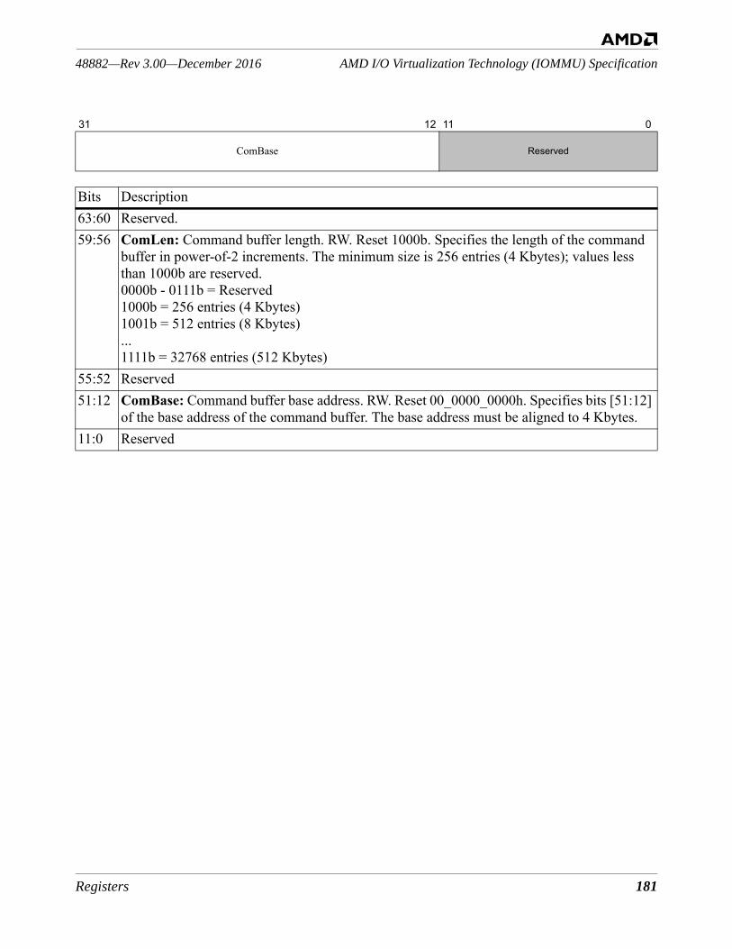
Registers 181
AMD I/O Virtualization Technology (IOMMU) Specification48882—Rev 3.00—December 2016
31 12 11 0
ComBase Reserved
Bits Description63:60 Reserved. 59:56 ComLen: Command buffer length. RW. Reset 1000b. Specifies the length of the command
buffer in power-of-2 increments. The minimum size is 256 entries (4 Kbytes); values less than 1000b are reserved.0000b - 0111b = Reserved1000b = 256 entries (4 Kbytes)1001b = 512 entries (8 Kbytes)...1111b = 32768 entries (512 Kbytes)
55:52 Reserved51:12 ComBase: Command buffer base address. RW. Reset 00_0000_0000h. Specifies bits [51:12]
of the base address of the command buffer. The base address must be aligned to 4 Kbytes.11:0 Reserved
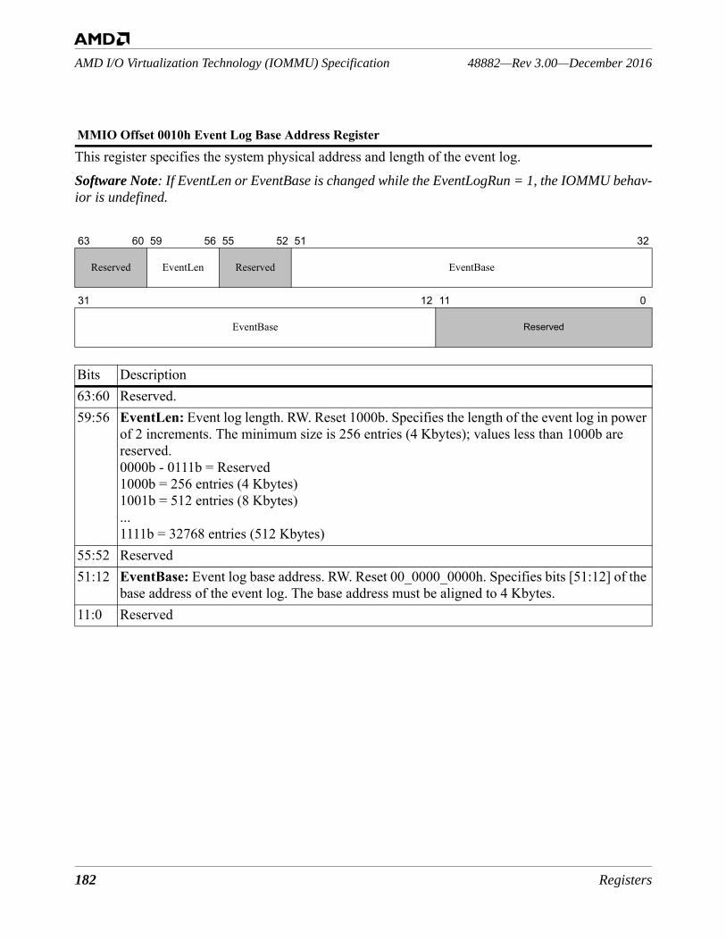
182 Registers
48882—Rev 3.00—December 2016AMD I/O Virtualization Technology (IOMMU) Specification
This register specifies the system physical address and length of the event log.Software Note: If EventLen or EventBase is changed while the EventLogRun = 1, the IOMMU behav-ior is undefined.
MMIO Offset 0010h Event Log Base Address Register
63 60 59 56 55 52 51 32
Reserved EventLen Reserved EventBase
31 12 11 0
EventBase Reserved
Bits Description63:60 Reserved. 59:56 EventLen: Event log length. RW. Reset 1000b. Specifies the length of the event log in power
of 2 increments. The minimum size is 256 entries (4 Kbytes); values less than 1000b are reserved.0000b - 0111b = Reserved1000b = 256 entries (4 Kbytes)1001b = 512 entries (8 Kbytes)...1111b = 32768 entries (512 Kbytes)
55:52 Reserved51:12 EventBase: Event log base address. RW. Reset 00_0000_0000h. Specifies bits [51:12] of the
base address of the event log. The base address must be aligned to 4 Kbytes.11:0 Reserved

Registers 183
AMD I/O Virtualization Technology (IOMMU) Specification48882—Rev 3.00—December 2016
This register controls the behavior of the IOMMU.
MMIO Offset 0018h IOMMU Control Register
63 44 43 42 41 40 39 38 37 36 34 33 32
Reserved
Dom
ainI
DPN
E
PprA
utoR
spAo
n
BlkS
topM
rkEn
Mar
cEn
PprA
utoR
spEn
Priv
AbrtE
n
Dev
TblS
egEn
Dua
lEve
ntLo
gEn
31 30 29 28 27 25 24 23 22 21 18 17 16 15 14 13 12 11 10 9 8 7 5 4 3 2 1 0
Dua
lPpr
LogE
n
GAI
ntEn
GAL
ogEn
GAMEn
SmiF
LogE
n
SlfW
Bdis
SmiF
En
CRWG
AEn
GTE
n
PPR
En
PprIn
tEn
PPR
LogE
n
Cm
dBuf
En
Isoc
Coh
eren
t
Res
Pass
PW
Pass
PW
InvT
imeO
ut
Com
Wai
tIntE
n
Even
tIntE
n
Even
tLog
En
HtT
unEn
Iom
muE
n
Bits Description63:44 Reserved.43 DomainIDPNE: 42 PprAutoRspAon: Peripheral Page Request Auto Response – Always On feature enable. RW.
Reset: 0b. 0 = PPR Auto Response – Always On feature is disabled. Enabling the PPR Auto Response – Always On feature requires setting this bit and PprAutoRspEn. When MMIO Offset 0030h[PprAutoRespSup] = 0, this field is reserved. See Section 2.6.4.4 [PPR Auto Response Always-on] on page 164.
41 BlkStopMrkEn. Block StopMark messages feature Enable RW. Reset: 1b. This feature, when supported, is enabled by default. When MMIO Offset 0030h[BlkStopMrkSup] = 0. this field is reserved. See Section 2.6.4.5 [Block StopMark Messages] on page 164.
40 MarcEn: Memory Address Routing and Control feature Enable. RW. Reset: 0b. 0 = MARC disabled. 1 = MARC is enabled. When MMIO Offset 0030h[MarcSup] = 00b, this field is reserved. See Section 2.9 [Memory Address Routing and Control (MARC)] on page 170.
39 PprAutoRspEn: Peripheral Page Request Automatic Response feature Enable. RW. Reset: 0b. 0 = PPR auto response is disabled. 1 = PPR auto response, if supported, is enabled. When MMIO Offset 0030h[PprAutoRespSup] = 0, this field is reserved. See Section 2.6.4.1 [PPR Auto Response] on page 163.
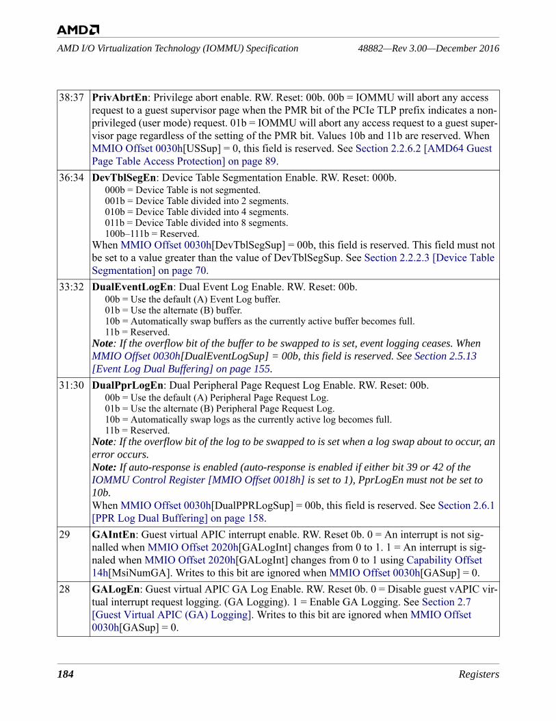
184 Registers
48882—Rev 3.00—December 2016AMD I/O Virtualization Technology (IOMMU) Specification
38:37 PrivAbrtEn: Privilege abort enable. RW. Reset: 00b. 00b = IOMMU will abort any access request to a guest supervisor page when the PMR bit of the PCIe TLP prefix indicates a non-privileged (user mode) request. 01b = IOMMU will abort any access request to a guest super-visor page regardless of the setting of the PMR bit. Values 10b and 11b are reserved. When MMIO Offset 0030h[USSup] = 0, this field is reserved. See Section 2.2.6.2 [AMD64 Guest Page Table Access Protection] on page 89.
36:34 DevTblSegEn: Device Table Segmentation Enable. RW. Reset: 000b. 000b = Device Table is not segmented. 001b = Device Table divided into 2 segments. 010b = Device Table divided into 4 segments. 011b = Device Table divided into 8 segments. 100b–111b = Reserved.
When MMIO Offset 0030h[DevTblSegSup] = 00b, this field is reserved. This field must not be set to a value greater than the value of DevTblSegSup. See Section 2.2.2.3 [Device Table Segmentation] on page 70.
33:32 DualEventLogEn: Dual Event Log Enable. RW. Reset: 00b. 00b = Use the default (A) Event Log buffer.01b = Use the alternate (B) buffer.10b = Automatically swap buffers as the currently active buffer becomes full.11b = Reserved.
Note: If the overflow bit of the buffer to be swapped to is set, event logging ceases. When MMIO Offset 0030h[DualEventLogSup] = 00b, this field is reserved. See Section 2.5.13 [Event Log Dual Buffering] on page 155.
31:30 DualPprLogEn: Dual Peripheral Page Request Log Enable. RW. Reset: 00b. 00b = Use the default (A) Peripheral Page Request Log.01b = Use the alternate (B) Peripheral Page Request Log.10b = Automatically swap logs as the currently active log becomes full.11b = Reserved.
Note: If the overflow bit of the log to be swapped to is set when a log swap about to occur, an error occurs. Note: If auto-response is enabled (auto-response is enabled if either bit 39 or 42 of the IOMMU Control Register [MMIO Offset 0018h] is set to 1), PprLogEn must not be set to 10b.When MMIO Offset 0030h[DualPPRLogSup] = 00b, this field is reserved. See Section 2.6.1 [PPR Log Dual Buffering] on page 158.
29 GAIntEn: Guest virtual APIC interrupt enable. RW. Reset 0b. 0 = An interrupt is not sig-nalled when MMIO Offset 2020h[GALogInt] changes from 0 to 1. 1 = An interrupt is sig-naled when MMIO Offset 2020h[GALogInt] changes from 0 to 1 using Capability Offset 14h[MsiNumGA]. Writes to this bit are ignored when MMIO Offset 0030h[GASup] = 0.
28 GALogEn: Guest virtual APIC GA Log Enable. RW. Reset 0b. 0 = Disable guest vAPIC vir-tual interrupt request logging. (GA Logging). 1 = Enable GA Logging. See Section 2.7 [Guest Virtual APIC (GA) Logging]. Writes to this bit are ignored when MMIO Offset 0030h[GASup] = 0.
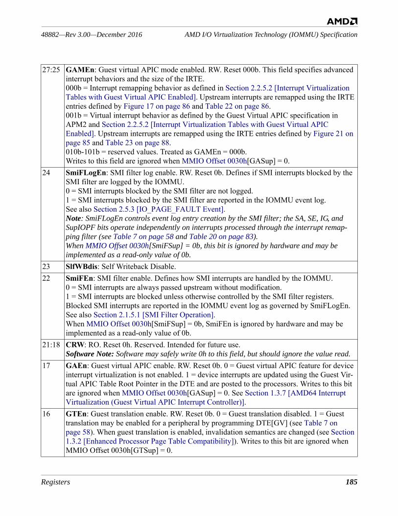
Registers 185
AMD I/O Virtualization Technology (IOMMU) Specification48882—Rev 3.00—December 2016
27:25 GAMEn: Guest virtual APIC mode enabled. RW. Reset 000b. This field specifies advanced interrupt behaviors and the size of the IRTE.000b = Interrupt remapping behavior as defined in Section 2.2.5.2 [Interrupt Virtualization Tables with Guest Virtual APIC Enabled]. Upstream interrupts are remapped using the IRTE entries defined by Figure 17 on page 86 and Table 22 on page 86.001b = Virtual interrupt behavior as defined by the Guest Virtual APIC specification in APM2 and Section 2.2.5.2 [Interrupt Virtualization Tables with Guest Virtual APIC Enabled]. Upstream interrupts are remapped using the IRTE entries defined by Figure 21 on page 85 and Table 23 on page 88. 010b-101b = reserved values. Treated as GAMEn = 000b.Writes to this field are ignored when MMIO Offset 0030h[GASup] = 0.
24 SmiFLogEn: SMI filter log enable. RW. Reset 0b. Defines if SMI interrupts blocked by the SMI filter are logged by the IOMMU. 0 = SMI interrupts blocked by the SMI filter are not logged. 1 = SMI interrupts blocked by the SMI filter are reported in the IOMMU event log.See also Section 2.5.3 [IO_PAGE_FAULT Event].Note: SmiFLogEn controls event log entry creation by the SMI filter; the SA, SE, IG, and SupIOPF bits operate independently on interrupts processed through the interrupt remap-ping filter (see Table 7 on page 58 and Table 20 on page 83).When MMIO Offset 0030h[SmiFSup] = 0b, this bit is ignored by hardware and may be implemented as a read-only value of 0b.
23 SlfWBdis: Self Writeback Disable. 22 SmiFEn: SMI filter enable. Defines how SMI interrupts are handled by the IOMMU.
0 = SMI interrupts are always passed upstream without modification. 1 = SMI interrupts are blocked unless otherwise controlled by the SMI filter registers. Blocked SMI interrupts are reported in the IOMMU event log as governed by SmiFLogEn. See also Section 2.1.5.1 [SMI Filter Operation].When MMIO Offset 0030h[SmiFSup] = 0b, SmiFEn is ignored by hardware and may be implemented as a read-only value of 0b.
21:18 CRW: RO. Reset 0h. Reserved. Intended for future use. Software Note: Software may safely write 0h to this field, but should ignore the value read.
17 GAEn: Guest virtual APIC enable. RW. Reset 0b. 0 = Guest virtual APIC feature for device interrupt virtualization is not enabled. 1 = device interrupts are updated using the Guest Vir-tual APIC Table Root Pointer in the DTE and are posted to the processors. Writes to this bit are ignored when MMIO Offset 0030h[GASup] = 0. See Section 1.3.7 [AMD64 Interrupt Virtualization (Guest Virtual APIC Interrupt Controller)].
16 GTEn: Guest translation enable. RW. Reset 0b. 0 = Guest translation disabled. 1 = Guest translation may be enabled for a peripheral by programming DTE[GV] (see Table 7 on page 58). When guest translation is enabled, invalidation semantics are changed (see Section 1.3.2 [Enhanced Processor Page Table Compatibility]). Writes to this bit are ignored when MMIO Offset 0030h[GTSup] = 0.
186 Registers
48882—Rev 3.00—December 2016AMD I/O Virtualization Technology (IOMMU) Specification
15 PPREn: Peripheral page request processing enable. RW. Reset 0b. 1 = Peripheral page requests are processed. 0 = PPR requests are treated as invalid device requests (see Section 2.5.9 [INVALID_DEVICE_REQUEST Event]). Writes to this bit are ignored when MMIO Offset 0030h[PPRSup] = 0.
14 PprIntEn: Peripheral page request interrupt enable. RW. Reset 0b. 1 = An interrupt is sig-nalled when MMIO Offset 2020h[PPRLogInt] = 1 using Capability Offset 10h[MsiNumPPR]. 0 = An interrupt is not signalled when MMIO Offset 2020h[PPRLogInt] = 1. Writes to this bit are ignored when MMIO Offset 0030h[PPRSup] = 0.
13 PPRLogEn: Peripheral page request log enable. RW. Reset 0b. 1 = The PPR Log Base Address Register [MMIO Offset 0038h] has been configured and peripheral page request events are written to the peripheral page request log when IommuEn has also been set. Writ-ing a 1 to this bit when MMIO Offset 2020h[PPRLogRun] = 1b has no effect. 0 = Peripheral page request logging is not enabled. Peripheral page requests are discarded when the periph-eral page request log is not enabled or when MMIO Offset 0030h[PPRSup] = 0.When IommuEn = 1b and PPREn = 1b, if software writes PPRLogEn with 1b, the IOMMU clears the PPRLogOverflow bit and sets the PPRLogRun bit in the IOMMU Status Register [MMIO Offset 2020h]. The IOMMU can now write new entries to the event log if there are usable entries available.Note: writes to this bit are ignored when MMIO Offset 0030h[PPRSup] = 0.Software Note: software can read MMIO Offset 2020h[PPRLogRun] to determine the status of peripheral page request log writing by the IOMMU.Note: the peripheral page request log and event log are independent.Software Note: the PPR Log Base Address Register [MMIO Offset 0038h], the IOMMU PPR Log Head Pointer Register [MMIO Offset 2030h], and the IOMMU PPR Log Tail Pointer Register [MMIO Offset 2038h] must be set prior to enabling the event log.
12 CmdBufEn: Command buffer enable. RW. Reset 0b. 1 = Start or restart command buffer processing. When CmdBufEn = 1b and IommuEn = 1b, the IOMMU starts fetching com-mands and sets MMIO Offset 2020h[CmdBufRun] to 1b. Writing a 1b to CmdBufEn when CmdBufRun = 1b has no effect. 0 = Halt command buffer processing. Writing a 0 to Cmd-BufEn causes the IOMMU to cease fetching new commands although commands previously fetched are completed. The IOMMU stops fetching commands upon reset and after events as specified in Section 2.5 [Event Logging]. See MMIO Offset 2020h[CmdBufRun].Note: see IOMMU Status Register [MMIO Offset 2020h] to determine the status of command buffer processing.Note: writing of event log entries is independently controlled by EventLogEn.Software Note: the Command Buffer Base Address Register [MMIO Offset 0008h], the Com-mand Buffer Head Pointer Register [MMIO Offset 2000h], and the Command Buffer Tail Pointer Register [MMIO Offset 2008h] must be set prior to enabling the IOMMU command buffer processor.
Registers 187
AMD I/O Virtualization Technology (IOMMU) Specification48882—Rev 3.00—December 2016
11 Isoc: Isochronous. RW. Reset 0b. This bit controls the state of the isochronous bit in the HyperTransport™ read request packet when the IOMMU issues I/O page table reads and Device Table reads on the HyperTransport™ link. 1 = Request packet to use isochronous channel. 0 = Request packet to use standard channel.Note: Platform firmware should set this bit to 1b for processors that support the isochronous channel.
10 Coherent:: Coherent. RW. Reset 1b. This bit controls the state of the coherent bit in the HyperTransport™ read request packet when the IOMMU issues Device Table reads on the HyperTransport™ link. 1 = Device table requests are snooped by the processor. 0 = Device table requests are not snooped by the processor. See SD in Table 7 on page 58.
9 ResPassPW: Response pass posted write. RW. Reset 0b. This bit controls the state of the ResPassPW bit in the HyperTransport™ read request packet when the IOMMU issues I/O page table reads and Device Table reads on the HyperTransport™ link. 1 = Response may pass posted requests. 0 = Response may not pass posted requests.
8 PassPW: Pass posted write. RW. Reset 0b. This bit controls the state of the PassPW bit in the HyperTransport™ read request packet when the IOMMU issues I/O page table reads and Device Table reads on the HyperTransport™ link. 1 = Request packet may pass posted requests. 0 = Request packet may not pass posted requests.
7:5 InvTimeOut: Invalidation time-out. RW. Reset 000b. This field specifies the invalidation time-out for IOTLB invalidation requests.
000b No time-out 001b 1 ms010b 10 ms 011b 100 ms100b 1 sec. 101b 10 sec.110b 100 sec. 111b reserved
4 ComWaitIntEn: Completion wait interrupt enable. RW. Reset 0b. 1 = An interrupt is sig-nalled when MMIO Offset 2020h[ComWaitInt] = 1 using Capability Offset 10h[MsiNum].
3 EventIntEn: Event log interrupt enable. RW. Reset 0b. 1 = An interrupt is signalled when MMIO Offset 2020h[EventLogInt] = 1 or when MMIO Offset 2020h[EventOverflow] = 1 using Capability Offset 10h[MsiNum].
188 Registers
48882—Rev 3.00—December 2016AMD I/O Virtualization Technology (IOMMU) Specification
2 EventLogEn: Event log enable. RW. Reset 0b. 1 = The Event Log Base Address Register [MMIO Offset 0010h] has been configured and all events detected are written to the event log when IommuEn has also been set. Writing a 1b to this bit when EventLogEn = 1b has no effect. 0 = Event logging is not enabled. Events are discarded when the event log is not enabled.When IommuEn = 1b and software changes EventLogEn from 0b to 1b, the IOMMU clears the EventOverflow bit and sets the EventLogRun bit in the IOMMU Status Register [MMIO Offset 2020h]. The IOMMU can now write new entries to the event log if there are usable entries available.Software Note: software can read MMIO Offset 2020h[EventLogRun] to determine the sta-tus of event log writing by the IOMMU.Note: the fetching of commands is independently controlled by CmdBufEn.Software Note: the Event Log Base Address Register [MMIO Offset 0010h], the Event Log Head Pointer Register [MMIO Offset 2010h], and the Event Log Tail Pointer Register [MMIO Offset 2018h] must be set prior to enabling the event log.
1 HtTunEn: HyperTransport™ tunnel translation enable. RW. Reset 0b. 1 = Upstream traffic received by the HyperTransport™ tunnel is translated by the IOMMU. 0 = Upstream traffic received by the HyperTransport™ tunnel is not translated by the IOMMU. The IOMMU ignores the state of this bit while IommuEn = 0. See the HtTunnel bit in the IOMMU Capa-bility Header [Capability Offset 00h].
0 IommuEn: IOMMU enable. RW. Reset 0b.1 = IOMMU enabled. All upstream transactions are processed by the IOMMU. The Device Table Base Address Register [MMIO Offset 0000h] must be configured by software before setting this bit. 0 = IOMMU is disabled and no upstream transactions are translated or remapped by the IOMMU. When disabled, the IOMMU reads no commands and creates no event log entries.

Registers 189
AMD I/O Virtualization Technology (IOMMU) Specification48882—Rev 3.00—December 2016
This register specifies the base DVA of the IOMMU exclusion range. Device accesses that target addresses in the exclusion range are neither translated nor access checked if the EX bit in the Device Table is set for the device or if the Allow bit is set in this register. Note that the exclusion range test is not applied to device transactions presenting a valid PASID TLP Prefix.A translation request for which the IOMMU exclusion range applies and I = 1b in the Device Table entry returns R = 1, W = 1, and a physical address that equals the requested virtual address. The response to a multi-page translation request in the IOMMU exclusion range is implementation-spe-cific.Software Note: A peripheral using a remote IOTLB may cache the results of a translation request to the exclusion range, so an INVALIDATE_IOTLB_PAGES command must be issued after changing the IOMMU exclusion range.
MMIO Offset 0020h IOMMU Exclusion Base Register
63 52 51 32
Reserved Exclusion Base Address[51:32]
31 12 11 2 1 0
Exclusion Base Address[31:12] Reserved
Allo
w
ExEn
Bits Description63:52 Reserved.51:12 Exclusion range base address. RW. Reset 00_0000_0000h. Specifies bits [51:12] of the
4Kbyte-aligned base address of the exclusion range.11:2 Reserved. 1 Allow: Allow all devices. RW. Reset 0b. 1 = All accesses to the exclusion range are for-
warded untranslated. 0 = The EX bit in the Device Table entry specifies if accesses to the exclusion range are translated.
0 ExEn: Exclusion range enable. RW. Reset 0b. 1 = The exclusion range is enabled. 0 = the exclusion range is disabled.
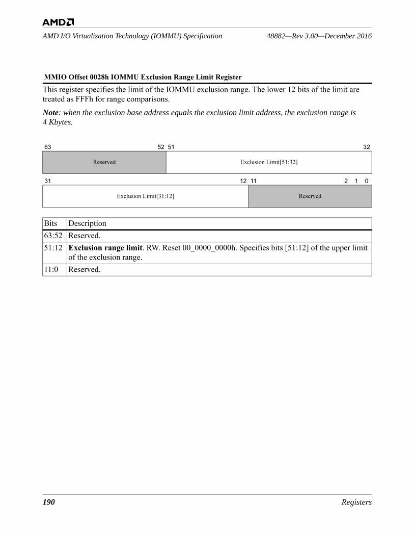
190 Registers
48882—Rev 3.00—December 2016AMD I/O Virtualization Technology (IOMMU) Specification
This register specifies the limit of the IOMMU exclusion range. The lower 12 bits of the limit are treated as FFFh for range comparisons.Note: when the exclusion base address equals the exclusion limit address, the exclusion range is 4 Kbytes.
MMIO Offset 0028h IOMMU Exclusion Range Limit Register
63 52 51 32
Reserved Exclusion Limit[51:32]
31 12 11 2 1 0
Exclusion Limit[31:12] Reserved
Bits Description63:52 Reserved.51:12 Exclusion range limit. RW. Reset 00_0000_0000h. Specifies bits [51:12] of the upper limit
of the exclusion range. 11:0 Reserved.
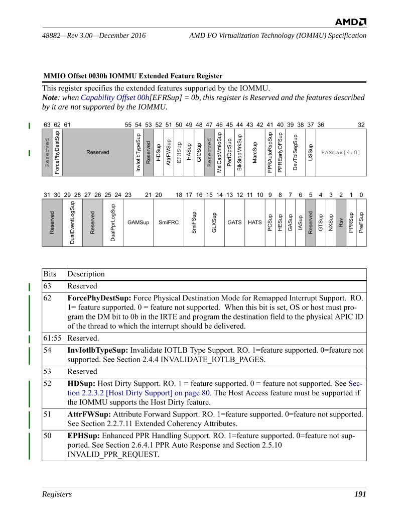
Registers 191
AMD I/O Virtualization Technology (IOMMU) Specification48882—Rev 3.00—December 2016
This register specifies the extended features supported by the IOMMU.Note: when Capability Offset 00h[EFRSup] = 0b, this register is Reserved and the features described by it are not supported by the IOMMU.
MMIO Offset 0030h IOMMU Extended Feature Register
63 62 61 55 54 53 52 51 50 49 48 47 46 45 44 43 42 41 40 39 38 37 36 32
Reserved
Forc
ePhy
Des
tSup
Reserved
InvI
otlb
Type
Sup
Res
erve
d
HD
Sup
AttrF
WSu
p
EPHSup
HAS
up
GIO
Sup
Reserved
Msi
Cap
Mm
ioSu
p
PerfO
ptSu
p
BlkS
topM
rkSu
p
Mar
cSup
PPR
Auto
Rsp
Sup
PPR
Early
OFS
up
Dev
TblS
egSu
p
USS
up
PASmax[4:0]
31 30 29 28 27 26 25 24 23 21 20 18 17 16 15 14 13 12 11 10 9 8 7 6 5 4 3 2 1 0
Res
erve
d
Dua
lEve
ntLo
gSup
Res
erve
d
Dua
lPpr
LogS
up
GAMSup SmiFRC
SmiF
Sup
GLX
Sup
GATS HATS
PCSu
p
HES
up
GAS
up
IASu
p
Res
erve
d
GTS
up
NXS
up
Rsv
PPR
Sup
PreF
Sup
Bits Description63 Reserved62 ForcePhyDestSup: Force Physical Destination Mode for Remapped Interrupt Support. RO.
1= feature supported. 0 = feature not supported. When this bit is set, OS or host must pro-gram the DM bit to 0b in the IRTE and program the destination field to the physical APIC ID of the thread to which the interrupt should be delivered.
61:55 Reserved. 54 InvIotlbTypeSup: Invalidate IOTLB Type Support. RO. 1=feature supported. 0=feature not
supported. See Section 2.4.4 INVALIDATE_IOTLB_PAGES.53 Reserved52 HDSup: Host Dirty Support. RO. 1 = feature supported. 0 = feature not supported. See Sec-
tion 2.2.3.2 [Host Dirty Support] on page 80. The Host Access feature must be supported if the IOMMU supports the Host Dirty feature.
51 AttrFWSup: Attribute Forward Support. RO. 1=feature supported. 0=feature not supported. See Section 2.2.7.11 Extended Coherency Attributes.
50 EPHSup: Enhanced PPR Handling Support. RO. 1=feature supported. 0=feature not sup-ported. See Section 2.6.4.1 PPR Auto Response and Section 2.5.10 INVALID_PPR_REQUEST.
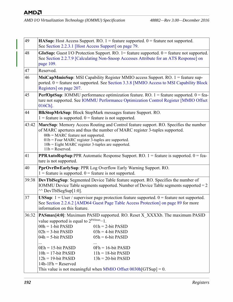
192 Registers
48882—Rev 3.00—December 2016AMD I/O Virtualization Technology (IOMMU) Specification
49 HASup: Host Access Support. RO. 1 = feature supported. 0 = feature not supported.See Section 2.2.3.1 [Host Access Support] on page 79.
48 GIoSup: Guest I/O Protection Support. RO. 1= feature supported. 0 = feature not supported.See Section 2.2.7.9 [Calculating Non-Snoop Accesses Attribute for an ATS Response] on page 109.
47 Reserved.46 MsiCapMmioSup: MSI Capability Register MMIO access Support. RO. 1 = feature sup-
ported. 0 = feature not supported. See Section 3.3.8 [MMIO Access to MSI Capability Block Registers] on page 207.
45 PerfOptSup: IOMMU performance optimization feature. RO. 1 = feature supported. 0 = fea-ture not supported. See IOMMU Performance Optimization Control Register [MMIO Offset 016Ch].
44 BlkStopMrkSup: Block StopMark messages feature Support. RO.1 = feature is supported. 0 = feature is not supported.
43:42 MarcSup: Memory Access Routing and Control feature support. RO. Specifies the number of MARC apertures and thus the number of MARC register 3-tuples supported.
00b = MARC feature not supported.01b = Four MARC register 3-tuples are supported.10b = Eight MARC register 3-tuples are supported.11b = Reserved.
41 PPRAutoRspSup:PPR Automatic Response Support. RO. 1 = feature is supported. 0 = fea-ture is not supported.
40 PprOvrflwEarlySup: PPR Log Overflow Early Warning Support. RO. 1 = feature is supported. 0 = feature is not supported.
39:38 DevTblSegSup: Segmented Device Table feature support. RO. Specifies the number of IOMMU Device Table segments supported. Number of Device Table segments supported = 2 ^^ DevTblSegSup[1:0].
37 USSup: 1 = User / supervisor page protection feature supported. 0 = feature not supported. See Section 2.2.6.2 [AMD64 Guest Page Table Access Protection] on page 89 for more information on this feature.
36:32 PASmax[4:0]: Maximum PASID supported. RO. Reset X_XXXXb. The maximum PASID value supported is equal to 2PASmax−1.00h = 1-bit PASID 01h = 2-bit PASID02h = 3-bit PASID 03h = 4-bit PASID04h = 5-bit PASID 05h = 6-bit PASID... ...0Eh = 15-bit PASID 0Fh = 16-bit PASID10h = 17-bit PASID 11h = 18-bit PASID12h = 19-bit PASID 13h = 20-bit PASID14h-1Fh = ReservedThis value is not meaningful when MMIO Offset 0030h[GTSup] = 0.
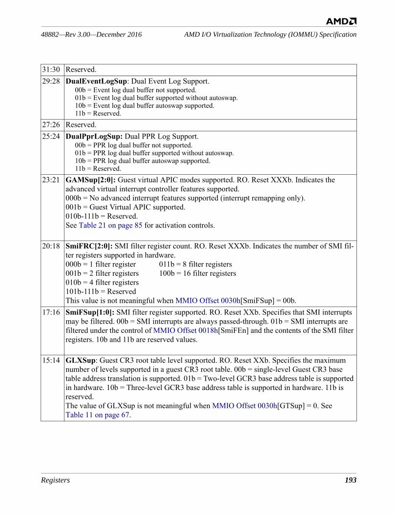
Registers 193
AMD I/O Virtualization Technology (IOMMU) Specification48882—Rev 3.00—December 2016
31:30 Reserved.29:28 DualEventLogSup: Dual Event Log Support.
00b = Event log dual buffer not supported.01b = Event log dual buffer supported without autoswap.10b = Event log dual buffer autoswap supported.11b = Reserved.
27:26 Reserved.25:24 DualPprLogSup: Dual PPR Log Support.
00b = PPR log dual buffer not supported.01b = PPR log dual buffer supported without autoswap.10b = PPR log dual buffer autoswap supported.11b = Reserved.
23:21 GAMSup[2:0]: Guest virtual APIC modes supported. RO. Reset XXXb. Indicates the advanced virtual interrupt controller features supported.000b = No advanced interrupt features supported (interrupt remapping only).001b = Guest Virtual APIC supported.010b-111b = Reserved.See Table 21 on page 85 for activation controls.
20:18 SmiFRC[2:0]: SMI filter register count. RO. Reset XXXb. Indicates the number of SMI fil-ter registers supported in hardware.000b = 1 filter register 011b = 8 filter registers001b = 2 filter registers 100b = 16 filter registers010b = 4 filter registers101b-111b = ReservedThis value is not meaningful when MMIO Offset 0030h[SmiFSup] = 00b.
17:16 SmiFSup[1:0]: SMI filter register supported. RO. Reset XXb. Specifies that SMI interrupts may be filtered. 00b = SMI interrupts are always passed-through. 01b = SMI interrupts are filtered under the control of MMIO Offset 0018h[SmiFEn] and the contents of the SMI filter registers. 10b and 11b are reserved values.
15:14 GLXSup: Guest CR3 root table level supported. RO. Reset XXb. Specifies the maximum number of levels supported in a guest CR3 root table. 00b = single-level Guest CR3 base table address translation is supported. 01b = Two-level GCR3 base address table is supported in hardware. 10b = Three-level GCR3 base address table is supported in hardware. 11b is reserved.The value of GLXSup is not meaningful when MMIO Offset 0030h[GTSup] = 0. See Table 11 on page 67.
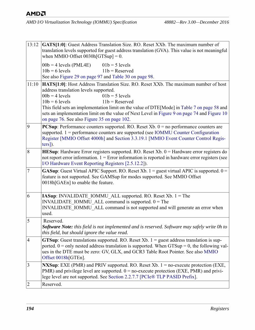
194 Registers
48882—Rev 3.00—December 2016AMD I/O Virtualization Technology (IOMMU) Specification
13:12 GATS[1:0]: Guest Address Translation Size. RO. Reset XXb. The maximum number of translation levels supported for guest address translation (GVA). This value is not meaningful when MMIO Offset 0030h[GTSup] = 0.
00b = 4 levels (PML4E) 01b = 5 levels10b = 6 levels 11b = ReservedSee also Figure 29 on page 97 and Table 30 on page 98.
11:10 HATS[1:0]: Host Address Translation Size. RO. Reset XXb. The maximum number of host address translation levels supported.00b = 4 levels 01b = 5 levels10b = 6 levels 11b = ReservedThis field sets an implementation limit on the value of DTE[Mode] in Table 7 on page 58 and sets an implementation limit on the value of Next Level in Figure 9 on page 74 and Figure 10 on page 76. See also Figure 35 on page 102.
9 PCSup: Performance counters supported. RO. Reset Xb. 0 = no performance counters are supported. 1 = performance counters are supported (see IOMMU Counter Configuration Register [MMIO Offset 4000h] and Section 3.3.19.1 [MMIO Event Counter Control Regis-ters]).
8 HESup: Hardware Error registers supported. RO. Reset Xb. 0 = Hardware error registers do not report error information. 1 = Error information is reported in hardware error registers (see I/O Hardware Event Reporting Registers [2.5.12.2]).
7 GASup: Guest Virtual APIC Support. RO. Reset Xb. 1 = guest virtual APIC is supported. 0 = feature is not supported. See GAMSup for modes supported. See MMIO Offset 0018h[GAEn] to enable the feature.
6 IASup: INVALIDATE_IOMMU_ALL supported. RO. Reset Xb. 1 = The INVALIDATE_IOMMU_ALL command is supported. 0 = The INVALIDATE_IOMMU_ALL command is not supported and will generate an error when used.
5 Reserved.Software Note: this field is not implemented and is reserved. Software may safely write 0h to this field, but should ignore the value read.
4 GTSup: Guest translations supported. RO. Reset Xb. 1 = guest address translation is sup-ported. 0 = only nested address translation is supported. When GTSup = 0, the following val-ues in the DTE must be zero: GV, GLX, and GCR3 Table Root Pointer. See also MMIO Offset 0018h[GTEn].
3 NXSup: EXE (PMR) and PRIV supported. RO. Reset Xb. 1 = no-execute protection (EXE, PMR) and privilege level are supported. 0 = no-execute protection (EXE, PMR) and privi-lege level are not supported. See Section 2.2.7.7 [PCIe® TLP PASID Prefix].
2 Reserved.
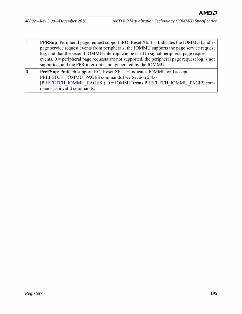
Registers 195
AMD I/O Virtualization Technology (IOMMU) Specification48882—Rev 3.00—December 2016
1 PPRSup: Peripheral page request support. RO. Reset Xb. 1 = Indicates the IOMMU handles page service request events from peripherals, the IOMMU supports the page service request log, and that the second IOMMU interrupt can be used to signal peripheral page request events. 0 = peripheral page requests are not supported, the peripheral page request log is not supported, and the PPR interrupt is not generated by the IOMMU.
0 PreFSup: Prefetch support. RO. Reset Xb. 1 = Indicates IOMMU will accept PREFETCH_IOMMU_PAGES commands (see Section 2.4.6 [PREFETCH_IOMMU_PAGES]). 0 = IOMMU treats PREFETCH_IOMMU_PAGES com-mands as invalid commands.
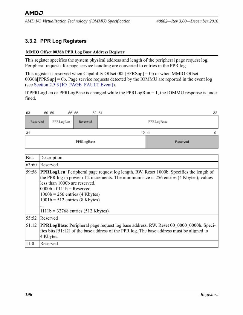
196 Registers
48882—Rev 3.00—December 2016AMD I/O Virtualization Technology (IOMMU) Specification
3.3.2 PPR Log Registers
This register specifies the system physical address and length of the peripheral page request log. Peripheral requests for page service handling are converted to entries in the PPR log.This register is reserved when Capability Offset 00h[EFRSup] = 0b or when MMIO Offset 0030h[PPRSup] = 0b. Page service requests detected by the IOMMU are reported in the event log (see Section 2.5.3 [IO_PAGE_FAULT Event]).If PPRLogLen or PPRLogBase is changed while the PPRLogRun = 1, the IOMMU response is unde-fined.
MMIO Offset 0038h PPR Log Base Address Register
63 60 59 56 55 52 51 32
Reserved PPRLogLen Reserved PPRLogBase
31 12 11 0
PPRLogBase Reserved
Bits Description63:60 Reserved. 59:56 PPRLogLen: Peripheral page request log length. RW. Reset 1000b. Specifies the length of
the PPR log in power of 2 increments. The minimum size is 256 entries (4 Kbytes); values less than 1000b are reserved.0000b - 0111b = Reserved1000b = 256 entries (4 Kbytes)1001b = 512 entries (8 Kbytes)...1111b = 32768 entries (512 Kbytes)
55:52 Reserved51:12 PPRLogBase: Peripheral page request log base address. RW. Reset 00_0000_0000h. Speci-
fies bits [51:12] of the base address of the PPR log. The base address must be aligned to 4 Kbytes.
11:0 Reserved
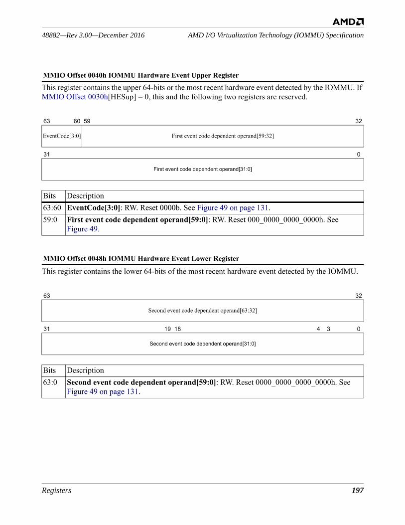
Registers 197
AMD I/O Virtualization Technology (IOMMU) Specification48882—Rev 3.00—December 2016
This register contains the upper 64-bits or the most recent hardware event detected by the IOMMU. If MMIO Offset 0030h[HESup] = 0, this and the following two registers are reserved.
This register contains the lower 64-bits of the most recent hardware event detected by the IOMMU.
MMIO Offset 0040h IOMMU Hardware Event Upper Register
63 60 59 32
EventCode[3:0] First event code dependent operand[59:32]
31 0
First event code dependent operand[31:0]
Bits Description63:60 EventCode[3:0]: RW. Reset 0000b. See Figure 49 on page 131.59:0 First event code dependent operand[59:0]: RW. Reset 000_0000_0000_0000h. See
Figure 49.
MMIO Offset 0048h IOMMU Hardware Event Lower Register
63 32
Second event code dependent operand[63:32]
31 19 18 4 3 0
Second event code dependent operand[31:0]
Bits Description63:0 Second event code dependent operand[59:0]: RW. Reset 0000_0000_0000_0000h. See
Figure 49 on page 131.
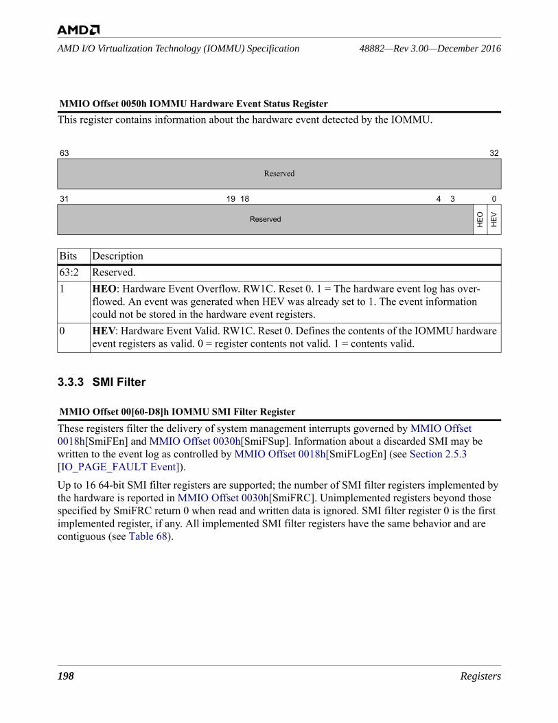
198 Registers
48882—Rev 3.00—December 2016AMD I/O Virtualization Technology (IOMMU) Specification
This register contains information about the hardware event detected by the IOMMU.
3.3.3 SMI Filter
These registers filter the delivery of system management interrupts governed by MMIO Offset 0018h[SmiFEn] and MMIO Offset 0030h[SmiFSup]. Information about a discarded SMI may be written to the event log as controlled by MMIO Offset 0018h[SmiFLogEn] (see Section 2.5.3 [IO_PAGE_FAULT Event]). Up to 16 64-bit SMI filter registers are supported; the number of SMI filter registers implemented by the hardware is reported in MMIO Offset 0030h[SmiFRC]. Unimplemented registers beyond those specified by SmiFRC return 0 when read and written data is ignored. SMI filter register 0 is the first implemented register, if any. All implemented SMI filter registers have the same behavior and are contiguous (see Table 68).
MMIO Offset 0050h IOMMU Hardware Event Status Register
63 32
Reserved
31 19 18 4 3 0
Reserved
HEO HEV
Bits Description63:2 Reserved.1 HEO: Hardware Event Overflow. RW1C. Reset 0. 1 = The hardware event log has over-
flowed. An event was generated when HEV was already set to 1. The event information could not be stored in the hardware event registers.
0 HEV: Hardware Event Valid. RW1C. Reset 0. Defines the contents of the IOMMU hardware event registers as valid. 0 = register contents not valid. 1 = contents valid.
MMIO Offset 00[60-D8]h IOMMU SMI Filter Register
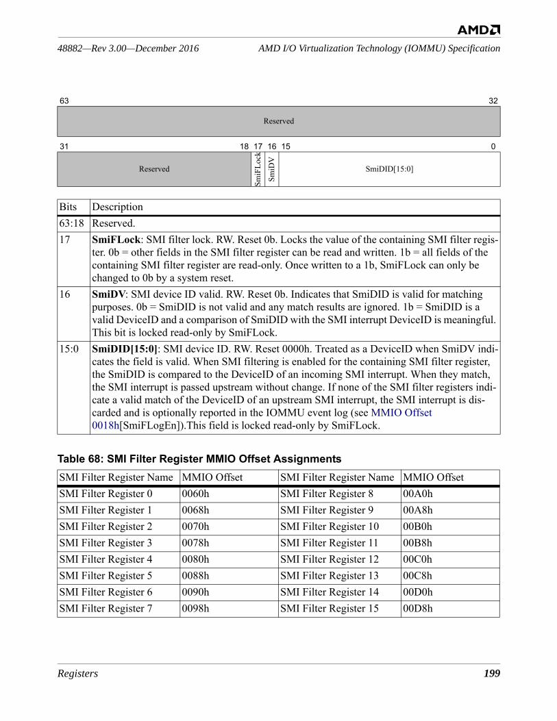
Registers 199
AMD I/O Virtualization Technology (IOMMU) Specification48882—Rev 3.00—December 2016
63 32
Reserved
31 18 17 16 15 0
Reserved
SmiF
Lock
SmiD
V
SmiDID[15:0]
Bits Description63:18 Reserved.17 SmiFLock: SMI filter lock. RW. Reset 0b. Locks the value of the containing SMI filter regis-
ter. 0b = other fields in the SMI filter register can be read and written. 1b = all fields of the containing SMI filter register are read-only. Once written to a 1b, SmiFLock can only be changed to 0b by a system reset.
16 SmiDV: SMI device ID valid. RW. Reset 0b. Indicates that SmiDID is valid for matching purposes. 0b = SmiDID is not valid and any match results are ignored. 1b = SmiDID is a valid DeviceID and a comparison of SmiDID with the SMI interrupt DeviceID is meaningful. This bit is locked read-only by SmiFLock.
15:0 SmiDID[15:0]: SMI device ID. RW. Reset 0000h. Treated as a DeviceID when SmiDV indi-cates the field is valid. When SMI filtering is enabled for the containing SMI filter register, the SmiDID is compared to the DeviceID of an incoming SMI interrupt. When they match, the SMI interrupt is passed upstream without change. If none of the SMI filter registers indi-cate a valid match of the DeviceID of an upstream SMI interrupt, the SMI interrupt is dis-carded and is optionally reported in the IOMMU event log (see MMIO Offset 0018h[SmiFLogEn]).This field is locked read-only by SmiFLock.
Table 68: SMI Filter Register MMIO Offset AssignmentsSMI Filter Register Name MMIO Offset SMI Filter Register Name MMIO OffsetSMI Filter Register 0 0060h SMI Filter Register 8 00A0hSMI Filter Register 1 0068h SMI Filter Register 9 00A8hSMI Filter Register 2 0070h SMI Filter Register 10 00B0hSMI Filter Register 3 0078h SMI Filter Register 11 00B8hSMI Filter Register 4 0080h SMI Filter Register 12 00C0hSMI Filter Register 5 0088h SMI Filter Register 13 00C8hSMI Filter Register 6 0090h SMI Filter Register 14 00D0hSMI Filter Register 7 0098h SMI Filter Register 15 00D8h
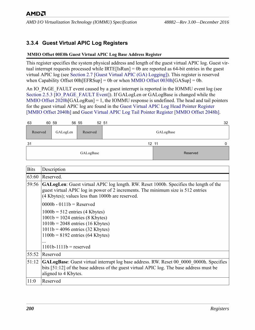
200 Registers
48882—Rev 3.00—December 2016AMD I/O Virtualization Technology (IOMMU) Specification
3.3.4 Guest Virtual APIC Log Registers
This register specifies the system physical address and length of the guest virtual APIC log. Guest vir-tual interrupt requests processed while IRTE[IsRun] = 0b are reported as 64-bit entries in the guest virtual APIC log (see Section 2.7 [Guest Virtual APIC (GA) Logging]). This register is reserved when Capability Offset 00h[EFRSup] = 0b or when MMIO Offset 0030h[GASup] = 0b. An IO_PAGE_FAULT event caused by a guest interrupt is reported in the IOMMU event log (see Section 2.5.3 [IO_PAGE_FAULT Event]). If GALogLen or GALogBase is changed while the MMIO Offset 2020h[GALogRun] = 1, the IOMMU response is undefined. The head and tail pointers for the guest virtual APIC log are found in the Guest Virtual APIC Log Head Pointer Register [MMIO Offset 2040h] and Guest Virtual APIC Log Tail Pointer Register [MMIO Offset 2048h].
MMIO Offset 00E0h Guest Virtual APIC Log Base Address Register
63 60 59 56 55 52 51 32
Reserved GALogLen Reserved GALogBase
31 12 11 0
GALogBase Reserved
Bits Description63:60 Reserved. 59:56 GALogLen: Guest virtual APIC log length. RW. Reset 1000b. Specifies the length of the
guest virtual APIC log in power of 2 increments. The minimum size is 512 entries (4 Kbytes); values less than 1000b are reserved.0000b - 0111b = Reserved1000b = 512 entries (4 Kbytes)1001b = 1024 entries (8 Kbytes)1010b = 2048 entries (16 Kbytes)1011b = 4096 entries (32 Kbytes)1100b = 8192 entries (64 Kbytes)...1101b-1111b = reserved
55:52 Reserved51:12 GALogBase: Guest virtual interrupt log base address. RW. Reset 00_0000_0000h. Specifies
bits [51:12] of the base address of the guest virtual APIC log. The base address must be aligned to 4 Kbytes.
11:0 Reserved
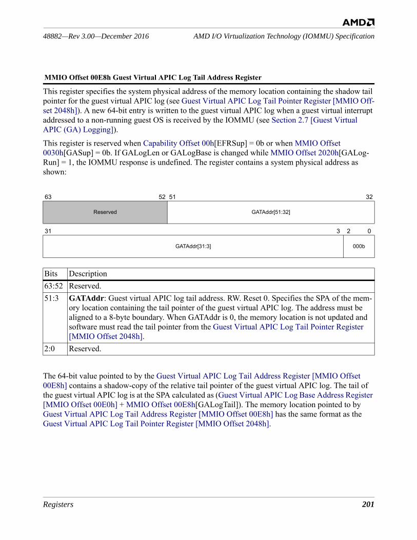
Registers 201
AMD I/O Virtualization Technology (IOMMU) Specification48882—Rev 3.00—December 2016
This register specifies the system physical address of the memory location containing the shadow tail pointer for the guest virtual APIC log (see Guest Virtual APIC Log Tail Pointer Register [MMIO Off-set 2048h]). A new 64-bit entry is written to the guest virtual APIC log when a guest virtual interrupt addressed to a non-running guest OS is received by the IOMMU (see Section 2.7 [Guest Virtual APIC (GA) Logging]). This register is reserved when Capability Offset 00h[EFRSup] = 0b or when MMIO Offset 0030h[GASup] = 0b. If GALogLen or GALogBase is changed while MMIO Offset 2020h[GALog-Run] = 1, the IOMMU response is undefined. The register contains a system physical address as shown:
The 64-bit value pointed to by the Guest Virtual APIC Log Tail Address Register [MMIO Offset 00E8h] contains a shadow-copy of the relative tail pointer of the guest virtual APIC log. The tail of the guest virtual APIC log is at the SPA calculated as (Guest Virtual APIC Log Base Address Register [MMIO Offset 00E0h] + MMIO Offset 00E8h[GALogTail]). The memory location pointed to by Guest Virtual APIC Log Tail Address Register [MMIO Offset 00E8h] has the same format as the Guest Virtual APIC Log Tail Pointer Register [MMIO Offset 2048h].
MMIO Offset 00E8h Guest Virtual APIC Log Tail Address Register
63 52 51 32
Reserved GATAddr[51:32]
31 3 2 0
GATAddr[31:3] 000b
Bits Description63:52 Reserved. 51:3 GATAddr: Guest virtual APIC log tail address. RW. Reset 0. Specifies the SPA of the mem-
ory location containing the tail pointer of the guest virtual APIC log. The address must be aligned to a 8-byte boundary. When GATAddr is 0, the memory location is not updated and software must read the tail pointer from the Guest Virtual APIC Log Tail Pointer Register [MMIO Offset 2048h].
2:0 Reserved.
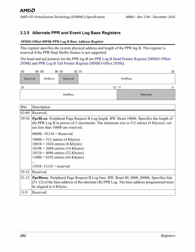
202 Registers
48882—Rev 3.00—December 2016AMD I/O Virtualization Technology (IOMMU) Specification
3.3.5 Alternate PPR and Event Log Base Registers
This register specifies the system physical address and length of the PPR log B. This register is reserved if the PPR Dual Buffer feature is not supported.The head and tail pointers for the PPR log B are PPR Log B Head Pointer Register [MMIO Offset 2050h] and PPR Log B Tail Pointer Register [MMIO Offset 2058h].
MMIO Offset 00F0h PPR Log B Base Address Register
63 60 59 56 55 52 51 32
Reserved PprBLen Reserved PprBbase
31 12 11 0
PprBbase Reserved
Bits Description63:60 Reserved. 59:56 PprBLen: Peripheral Page Request B Log length. RW. Reset 1000b. Specifies the length of
the PPR Log B in power-of-2 increments. The minimum size is 512 entries (4 Kbytes); val-ues less than 1000b are reserved.0000b - 0111b = Reserved1000b = 512 entries (4 Kbytes)1001b = 1024 entries (8 Kbytes)1010b = 2048 entries (16 Kbytes)1011b = 4096 entries (32 Kbytes)1100b = 8192 entries (64 Kbytes)...1101b–1111b = reserved
55:52 Reserved51:12 PprBbase: Peripheral Page Request B Log base. RW. Reset 00_0000_0000h. Specifies bits
[51:12] of the base address of the alternate (B) PPR Log. The base address programmed must be aligned to 4 Kbytes.
11:0 Reserved
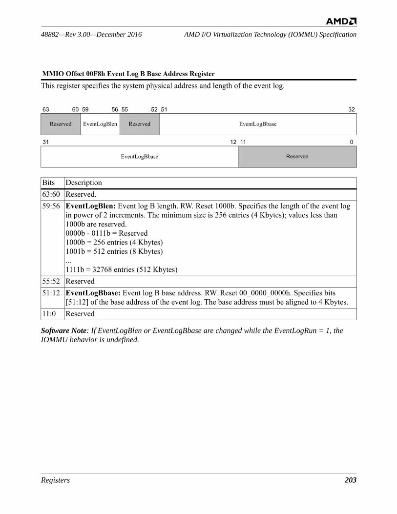
Registers 203
AMD I/O Virtualization Technology (IOMMU) Specification48882—Rev 3.00—December 2016
This register specifies the system physical address and length of the event log.
Software Note: If EventLogBlen or EventLogBbase are changed while the EventLogRun = 1, the IOMMU behavior is undefined.
MMIO Offset 00F8h Event Log B Base Address Register
63 60 59 56 55 52 51 32
Reserved EventLogBlen Reserved EventLogBbase
31 12 11 0
EventLogBbase Reserved
Bits Description63:60 Reserved. 59:56 EventLogBlen: Event log B length. RW. Reset 1000b. Specifies the length of the event log
in power of 2 increments. The minimum size is 256 entries (4 Kbytes); values less than 1000b are reserved.0000b - 0111b = Reserved1000b = 256 entries (4 Kbytes)1001b = 512 entries (8 Kbytes)...1111b = 32768 entries (512 Kbytes)
55:52 Reserved51:12 EventLogBbase: Event log B base address. RW. Reset 00_0000_0000h. Specifies bits
[51:12] of the base address of the event log. The base address must be aligned to 4 Kbytes.11:0 Reserved
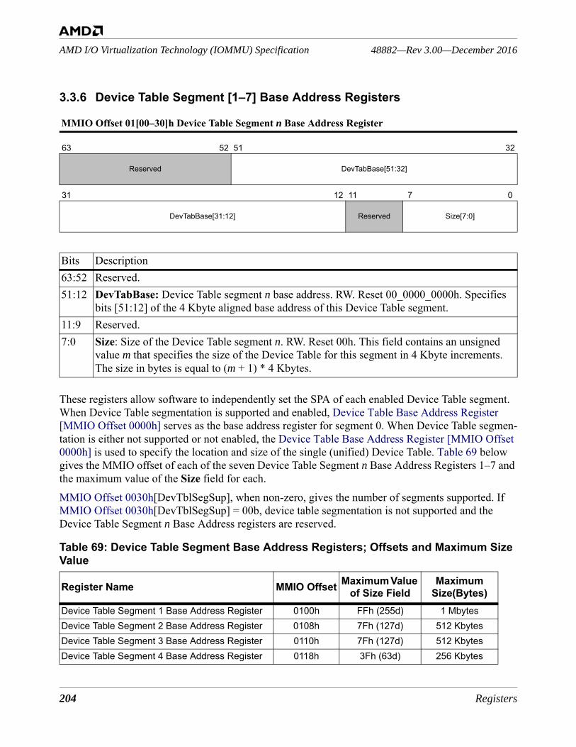
204 Registers
48882—Rev 3.00—December 2016AMD I/O Virtualization Technology (IOMMU) Specification
3.3.6 Device Table Segment [1–7] Base Address Registers
These registers allow software to independently set the SPA of each enabled Device Table segment. When Device Table segmentation is supported and enabled, Device Table Base Address Register [MMIO Offset 0000h] serves as the base address register for segment 0. When Device Table segmen-tation is either not supported or not enabled, the Device Table Base Address Register [MMIO Offset 0000h] is used to specify the location and size of the single (unified) Device Table. Table 69 below gives the MMIO offset of each of the seven Device Table Segment n Base Address Registers 1–7 and the maximum value of the Size field for each.MMIO Offset 0030h[DevTblSegSup], when non-zero, gives the number of segments supported. If MMIO Offset 0030h[DevTblSegSup] = 00b, device table segmentation is not supported and the Device Table Segment n Base Address registers are reserved.
MMIO Offset 01[00–30]h Device Table Segment n Base Address Register
63 52 51 32
Reserved DevTabBase[51:32]
31 12 11 7 0
DevTabBase[31:12] Reserved Size[7:0]
Bits Description63:52 Reserved. 51:12 DevTabBase: Device Table segment n base address. RW. Reset 00_0000_0000h. Specifies
bits [51:12] of the 4 Kbyte aligned base address of this Device Table segment.11:9 Reserved.7:0 Size: Size of the Device Table segment n. RW. Reset 00h. This field contains an unsigned
value m that specifies the size of the Device Table for this segment in 4 Kbyte increments. The size in bytes is equal to (m + 1) * 4 Kbytes.
Table 69: Device Table Segment Base Address Registers; Offsets and Maximum Size Value
Register Name MMIO Offset Maximum Value of Size Field
Maximum Size(Bytes)
Device Table Segment 1 Base Address Register 0100h FFh (255d) 1 MbytesDevice Table Segment 2 Base Address Register 0108h 7Fh (127d) 512 KbytesDevice Table Segment 3 Base Address Register 0110h 7Fh (127d) 512 KbytesDevice Table Segment 4 Base Address Register 0118h 3Fh (63d) 256 Kbytes
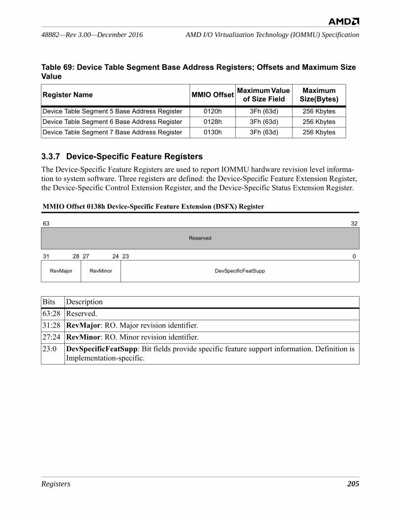
Registers 205
AMD I/O Virtualization Technology (IOMMU) Specification48882—Rev 3.00—December 2016
3.3.7 Device-Specific Feature RegistersThe Device-Specific Feature Registers are used to report IOMMU hardware revision level informa-tion to system software. Three registers are defined: the Device-Specific Feature Extension Register, the Device-Specific Control Extension Register, and the Device-Specific Status Extension Register.
Device Table Segment 5 Base Address Register 0120h 3Fh (63d) 256 KbytesDevice Table Segment 6 Base Address Register 0128h 3Fh (63d) 256 KbytesDevice Table Segment 7 Base Address Register 0130h 3Fh (63d) 256 Kbytes
MMIO Offset 0138h Device-Specific Feature Extension (DSFX) Register
63 32
Reserved
31 28 27 24 23 0
RevMajor RevMinor DevSpecificFeatSupp
Bits Description63:28 Reserved. 31:28 RevMajor: RO. Major revision identifier.27:24 RevMinor: RO. Minor revision identifier.23:0 DevSpecificFeatSupp: Bit fields provide specific feature support information. Definition is
Implementation-specific.
Table 69: Device Table Segment Base Address Registers; Offsets and Maximum Size Value
Register Name MMIO Offset Maximum Value of Size Field
Maximum Size(Bytes)

206 Registers
48882—Rev 3.00—December 2016AMD I/O Virtualization Technology (IOMMU) Specification
MMIO Offset 0140h Device-Specific Control Extension (DSCX) Register
63 32
Reserved
31 28 27 24 23 0
RevMajor RevMinor DevSpecificFeatCntrl
Bits Description63:28 Reserved. 31:28 RevMajor: RO. Major revision identifier.27:24 RevMinor: RO. Minor revision identifier.23:0 DevSpecificFeatCntrl: RW. Reset 00_0000h. Fields (to be defined) used to control features
reported in the DSFX register.
MMIO Offset 0148h Device-Specific Status Extension (DSSX) Register
63 32
Reserved
31 28 27 24 23 0
RevMajor RevMinor DevSpecificFeatStatus
Bits Description63:28 Reserved. 31:28 RevMajor: RO. Major revision identifier.27:24 RevMinor: RO. Minor revision identifier.23:0 DevSpecificFeatStatus: RW. Reset 00_0000h. Fields (to be defined) used to report the cur-
rent status of features reported in the DSFX register.
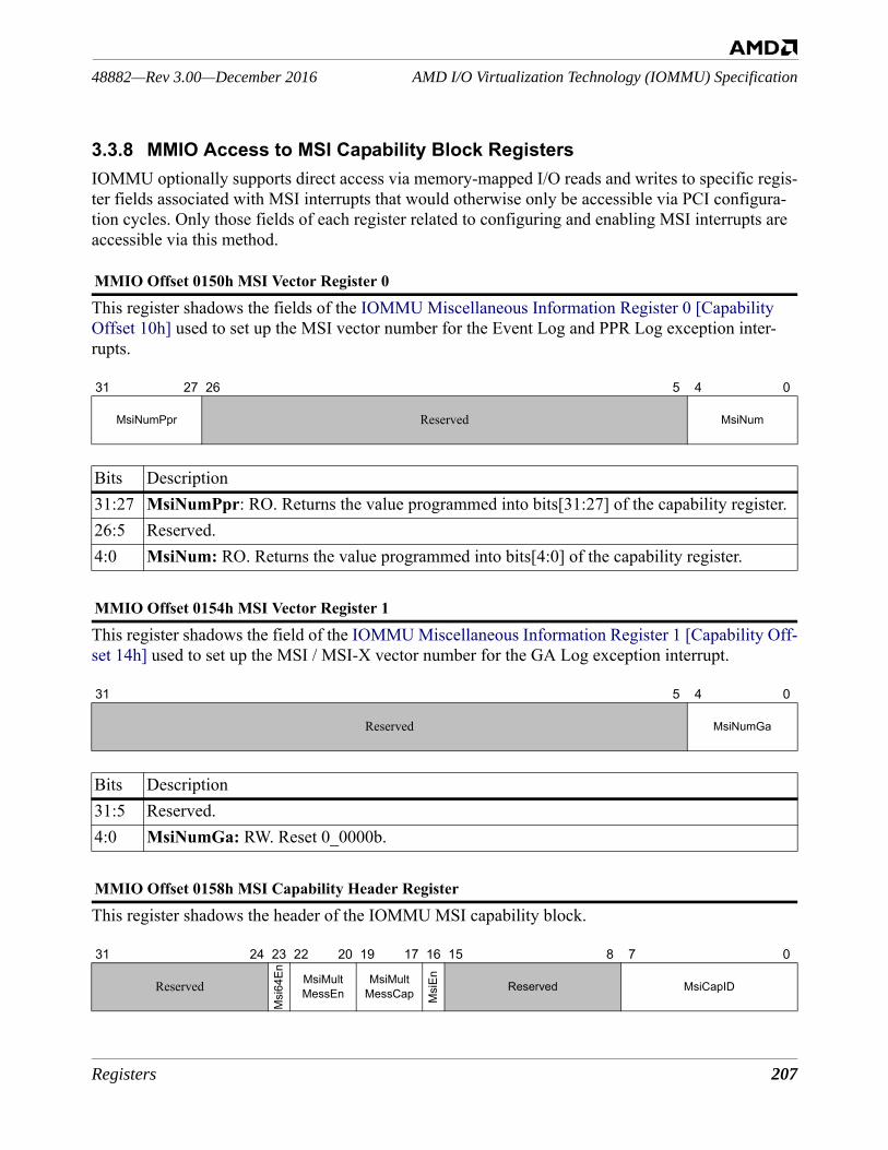
Registers 207
AMD I/O Virtualization Technology (IOMMU) Specification48882—Rev 3.00—December 2016
3.3.8 MMIO Access to MSI Capability Block RegistersIOMMU optionally supports direct access via memory-mapped I/O reads and writes to specific regis-ter fields associated with MSI interrupts that would otherwise only be accessible via PCI configura-tion cycles. Only those fields of each register related to configuring and enabling MSI interrupts are accessible via this method.
This register shadows the fields of the IOMMU Miscellaneous Information Register 0 [Capability Offset 10h] used to set up the MSI vector number for the Event Log and PPR Log exception inter-rupts.
This register shadows the field of the IOMMU Miscellaneous Information Register 1 [Capability Off-set 14h] used to set up the MSI / MSI-X vector number for the GA Log exception interrupt.
This register shadows the header of the IOMMU MSI capability block.
MMIO Offset 0150h MSI Vector Register 0
31 27 26 5 4 0
MsiNumPpr Reserved MsiNum
Bits Description31:27 MsiNumPpr: RO. Returns the value programmed into bits[31:27] of the capability register.26:5 Reserved.4:0 MsiNum: RO. Returns the value programmed into bits[4:0] of the capability register.
MMIO Offset 0154h MSI Vector Register 1
31 5 4 0
Reserved MsiNumGa
Bits Description31:5 Reserved.4:0 MsiNumGa: RW. Reset 0_0000b.
MMIO Offset 0158h MSI Capability Header Register
31 24 23 22 20 19 17 16 15 8 7 0
Reserved
Msi
64En MsiMult
MessEnMsiMult
MessCap Msi
En Reserved MsiCapID
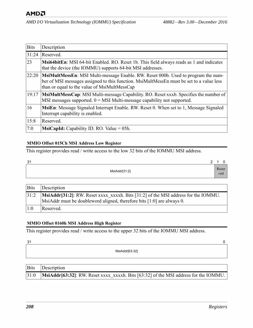
208 Registers
48882—Rev 3.00—December 2016AMD I/O Virtualization Technology (IOMMU) Specification
This register provides read / write access to the low 32 bits of the IOMMU MSI address.
This register provides read / write access to the upper 32 bits of the IOMMU MSI address.
Bits Description31:24 Reserved.23 Msi64bitEn: MSI 64-bit Enabled. RO. Reset 1b. This field always reads as 1 and indicates
that the device (the IOMMU) supports 64-bit MSI addresses.22:20 MsiMultMessEn: MSI Multi-message Enable. RW. Reset 000b. Used to program the num-
ber of MSI messages assigned to this function. MsiMultMessEn must be set to a value less than or equal to the value of MsiMultMessCap
19:17 MsiMultMessCap: MSI Multi-message Capability. RO. Reset xxxb. Specifies the number of MSI messages supported. 0 = MSI Multi-message capability not supported.
16 MsiEn: Message Signaled Interrupt Enable. RW. Reset 0. When set to 1, Message Signaled Interrupt capability is enabled.
15:8 Reserved.7:0 MsiCapId: Capability ID. RO. Value = 05h.
MMIO Offset 015Ch MSI Address Low Register
31 2 1 0
MsiAddr[31:2] Reserved
Bits Description31:2 MsiAddr[31:2]: RW. Reset xxxx_xxxxh. Bits [31:2] of the MSI address for the IOMMU.
MsiAddr must be doubleword aligned, therefore bits [1:0] are always 0.1:0 Reserved.
MMIO Offset 0160h MSI Address High Register
31 0
MsiAddr[63:32]
Bits Description31:0 MsiAddr[63:32]: RW. Reset xxxx_xxxxh. Bits [63:32] of the MSI address for the IOMMU.
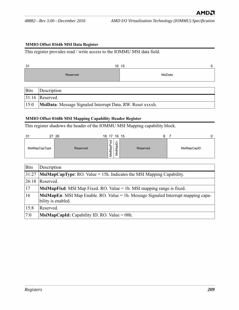
Registers 209
AMD I/O Virtualization Technology (IOMMU) Specification48882—Rev 3.00—December 2016
This register provides read / write access to the IOMMU MSI data field.
This register shadows the header of the IOMMU MSI Mapping capability block.
MMIO Offset 0164h MSI Data Register
31 16 15 0
Reserved MsiData
Bits Description31:16 Reserved.15:0 MsiData: Message Signaled Interrupt Data. RW. Reset xxxxh.
MMIO Offset 0168h MSI Mapping Capability Header Register
31 27 26 18 17 16 15 8 7 0
MsiMapCapType Reserved
Msi
Map
Fixd
Msi
Map
En
Reserved MsiMapCapID
Bits Description31:27 MsiMapCapType: RO. Value = 15h. Indicates the MSI Mapping Capability.26:18 Reserved.17 MsiMapFixd: MSI Map Fixed. RO. Value = 1b. MSI mapping range is fixed.16 MsiMapEn: MSI Map Enable. RO. Value = 1b. Message Signaled Interrupt mapping capa-
bility is enabled.15:8 Reserved.7:0 MsiMapCapId: Capability ID. RO. Value = 08h.
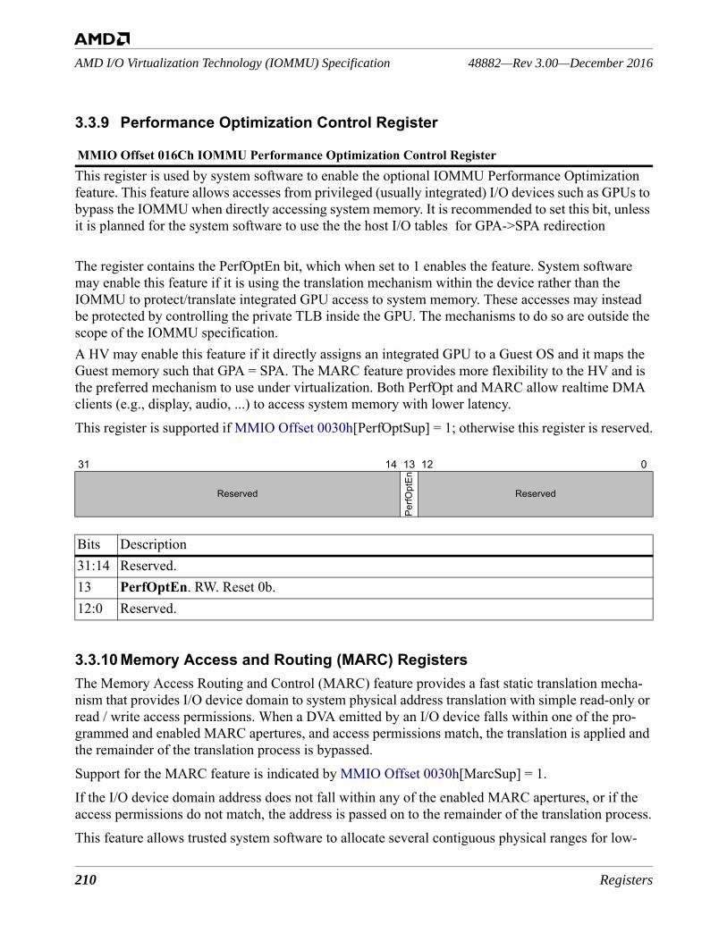
210 Registers
48882—Rev 3.00—December 2016AMD I/O Virtualization Technology (IOMMU) Specification
3.3.9 Performance Optimization Control Register
This register is used by system software to enable the optional IOMMU Performance Optimization feature. This feature allows accesses from privileged (usually integrated) I/O devices such as GPUs to bypass the IOMMU when directly accessing system memory. It is recommended to set this bit, unless it is planned for the system software to use the the host I/O tables for GPA->SPA redirection
The register contains the PerfOptEn bit, which when set to 1 enables the feature. System software may enable this feature if it is using the translation mechanism within the device rather than the IOMMU to protect/translate integrated GPU access to system memory. These accesses may instead be protected by controlling the private TLB inside the GPU. The mechanisms to do so are outside the scope of the IOMMU specification. A HV may enable this feature if it directly assigns an integrated GPU to a Guest OS and it maps the Guest memory such that GPA = SPA. The MARC feature provides more flexibility to the HV and is the preferred mechanism to use under virtualization. Both PerfOpt and MARC allow realtime DMA clients (e.g., display, audio, ...) to access system memory with lower latency. This register is supported if MMIO Offset 0030h[PerfOptSup] = 1; otherwise this register is reserved.
3.3.10 Memory Access and Routing (MARC) RegistersThe Memory Access Routing and Control (MARC) feature provides a fast static translation mecha-nism that provides I/O device domain to system physical address translation with simple read-only or read / write access permissions. When a DVA emitted by an I/O device falls within one of the pro-grammed and enabled MARC apertures, and access permissions match, the translation is applied and the remainder of the translation process is bypassed.Support for the MARC feature is indicated by MMIO Offset 0030h[MarcSup] = 1.If the I/O device domain address does not fall within any of the enabled MARC apertures, or if the access permissions do not match, the address is passed on to the remainder of the translation process.This feature allows trusted system software to allocate several contiguous physical ranges for low-
MMIO Offset 016Ch IOMMU Performance Optimization Control Register
31 14 13 12 0
Reserved
PerfO
ptEn
Reserved
Bits Description31:14 Reserved.13 PerfOptEn. RW. Reset 0b. 12:0 Reserved.
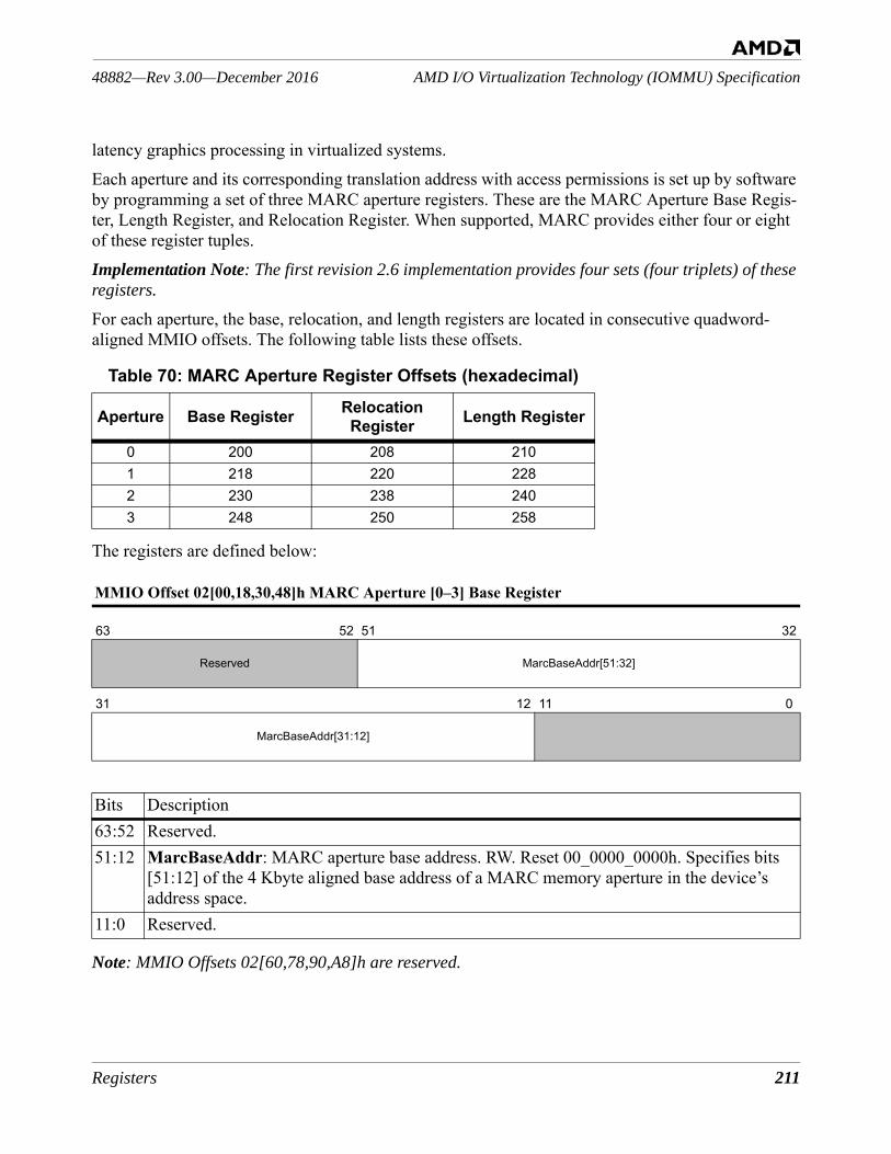
Registers 211
AMD I/O Virtualization Technology (IOMMU) Specification48882—Rev 3.00—December 2016
latency graphics processing in virtualized systems.Each aperture and its corresponding translation address with access permissions is set up by software by programming a set of three MARC aperture registers. These are the MARC Aperture Base Regis-ter, Length Register, and Relocation Register. When supported, MARC provides either four or eight of these register tuples.Implementation Note: The first revision 2.6 implementation provides four sets (four triplets) of these registers.
For each aperture, the base, relocation, and length registers are located in consecutive quadword-aligned MMIO offsets. The following table lists these offsets.
The registers are defined below:
Note: MMIO Offsets 02[60,78,90,A8]h are reserved.
Table 70: MARC Aperture Register Offsets (hexadecimal)
Aperture Base Register Relocation Register Length Register
0 200 208 2101 218 220 2282 230 238 2403 248 250 258
MMIO Offset 02[00,18,30,48]h MARC Aperture [0–3] Base Register
63 52 51 32
Reserved MarcBaseAddr[51:32]
31 12 11 0
MarcBaseAddr[31:12]
Bits Description63:52 Reserved.51:12 MarcBaseAddr: MARC aperture base address. RW. Reset 00_0000_0000h. Specifies bits
[51:12] of the 4 Kbyte aligned base address of a MARC memory aperture in the device’s address space.
11:0 Reserved.
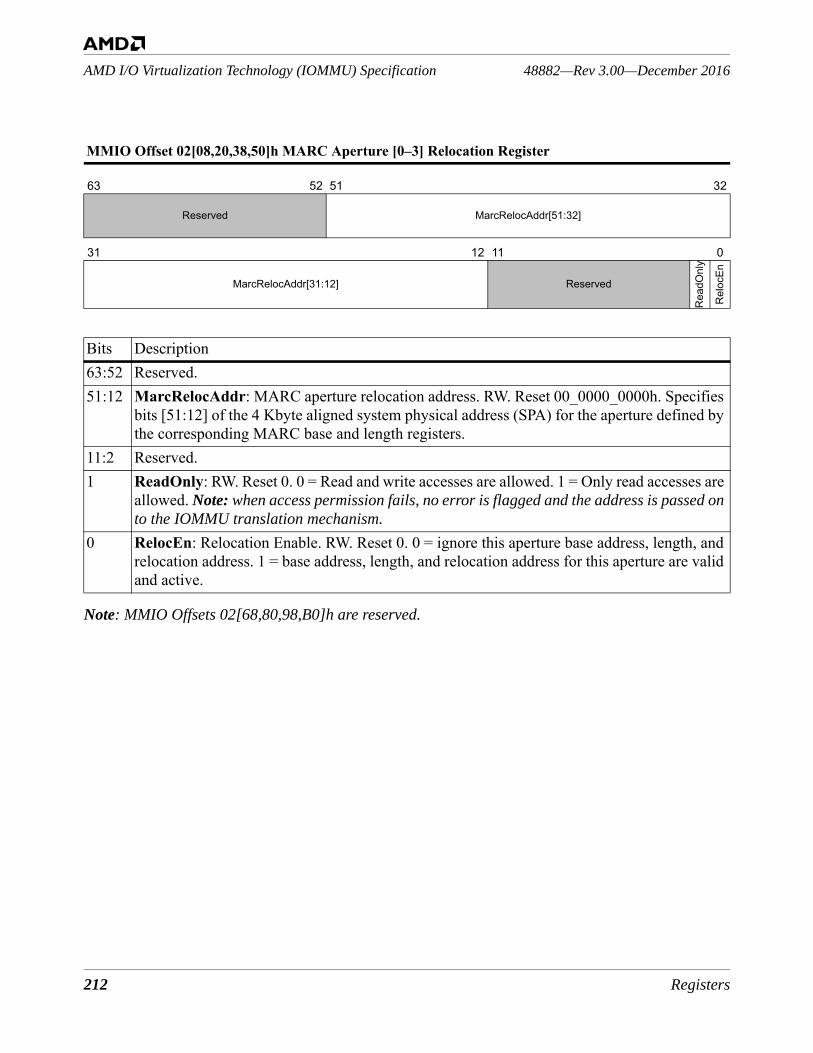
212 Registers
48882—Rev 3.00—December 2016AMD I/O Virtualization Technology (IOMMU) Specification
Note: MMIO Offsets 02[68,80,98,B0]h are reserved.
MMIO Offset 02[08,20,38,50]h MARC Aperture [0–3] Relocation Register
63 52 51 32
Reserved MarcRelocAddr[51:32]
31 12 11 0
MarcRelocAddr[31:12] Reserved
Rea
dOnl
y
Rel
ocEn
Bits Description63:52 Reserved.51:12 MarcRelocAddr: MARC aperture relocation address. RW. Reset 00_0000_0000h. Specifies
bits [51:12] of the 4 Kbyte aligned system physical address (SPA) for the aperture defined by the corresponding MARC base and length registers.
11:2 Reserved.1 ReadOnly: RW. Reset 0. 0 = Read and write accesses are allowed. 1 = Only read accesses are
allowed. Note: when access permission fails, no error is flagged and the address is passed on to the IOMMU translation mechanism.
0 RelocEn: Relocation Enable. RW. Reset 0. 0 = ignore this aperture base address, length, and relocation address. 1 = base address, length, and relocation address for this aperture are valid and active.
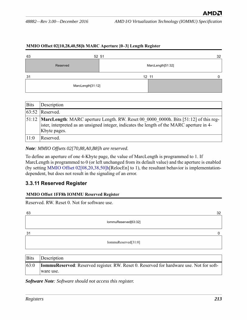
Registers 213
AMD I/O Virtualization Technology (IOMMU) Specification48882—Rev 3.00—December 2016
Note: MMIO Offsets 02[70,88,A0,B8]h are reserved.
To define an aperture of one 4-Kbyte page, the value of MarcLength is programmed to 1. If MarcLength is programmed to 0 (or left unchanged from its default value) and the aperture is enabled (by setting MMIO Offset 02[08,20,38,50]h[RelocEn] to 1), the resultant behavior is implementation-dependent, but does not result in the signaling of an error.
3.3.11 Reserved Register
Reserved. RW. Reset 0. Not for software use.
Software Note: Software should not access this register.
MMIO Offset 02[10,28,40,58]h MARC Aperture [0–3] Length Register
63 52 51 32
Reserved MarcLength[51:32]
31 12 11 0
MarcLength[31:12]
Bits Description63:52 Reserved.51:12 MarcLength: MARC aperture Length. RW. Reset 00_0000_0000h. Bits [51:12] of this reg-
ister, interpreted as an unsigned integer, indicates the length of the MARC aperture in 4-Kbyte pages.
11:0 Reserved.
MMIO Offset 1FF8h IOMMU Reserved Register
63 32
IommuReserved[63:32]
31 0
IommuReserved[31:0]
Bits Description63:0 IommuReserved: Reserved register. RW. Reset 0. Reserved for hardware use. Not for soft-
ware use.
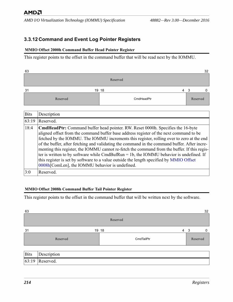
214 Registers
48882—Rev 3.00—December 2016AMD I/O Virtualization Technology (IOMMU) Specification
3.3.12 Command and Event Log Pointer Registers
This register points to the offset in the command buffer that will be read next by the IOMMU.
This register points to the offset in the command buffer that will be written next by the software.
MMIO Offset 2000h Command Buffer Head Pointer Register
63 32
Reserved
31 19 18 4 3 0
Reserved CmdHeadPtr Reserved
Bits Description63:19 Reserved. 18:4 CmdHeadPtr: Command buffer head pointer. RW. Reset 0000h. Specifies the 16-byte
aligned offset from the command buffer base address register of the next command to be fetched by the IOMMU. The IOMMU increments this register, rolling over to zero at the end of the buffer, after fetching and validating the command in the command buffer. After incre-menting this register, the IOMMU cannot re-fetch the command from the buffer. If this regis-ter is written to by software while CmdBufRun = 1b, the IOMMU behavior is undefined. If this register is set by software to a value outside the length specified by MMIO Offset 0008h[ComLen], the IOMMU behavior is undefined.
3:0 Reserved.
MMIO Offset 2008h Command Buffer Tail Pointer Register
63 32
Reserved
31 19 18 4 3 0
Reserved CmdTailPtr Reserved
Bits Description63:19 Reserved.
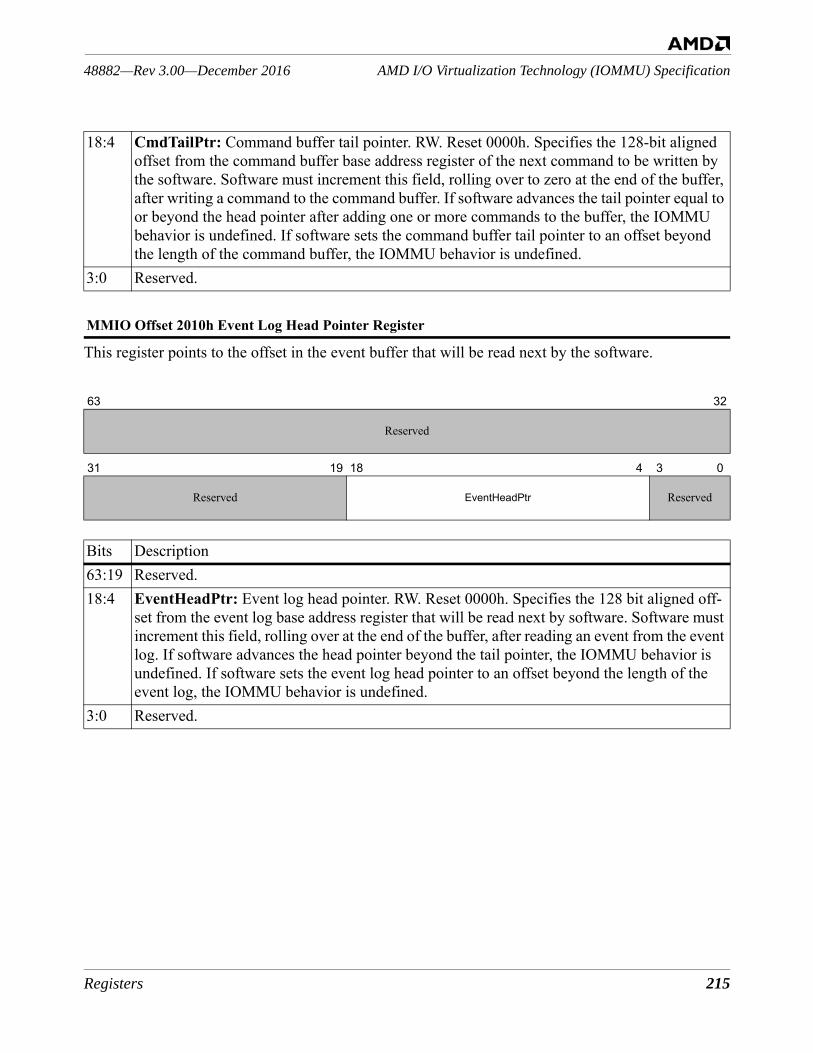
Registers 215
AMD I/O Virtualization Technology (IOMMU) Specification48882—Rev 3.00—December 2016
This register points to the offset in the event buffer that will be read next by the software.
18:4 CmdTailPtr: Command buffer tail pointer. RW. Reset 0000h. Specifies the 128-bit aligned offset from the command buffer base address register of the next command to be written by the software. Software must increment this field, rolling over to zero at the end of the buffer, after writing a command to the command buffer. If software advances the tail pointer equal to or beyond the head pointer after adding one or more commands to the buffer, the IOMMU behavior is undefined. If software sets the command buffer tail pointer to an offset beyond the length of the command buffer, the IOMMU behavior is undefined.
3:0 Reserved.
MMIO Offset 2010h Event Log Head Pointer Register
63 32
Reserved
31 19 18 4 3 0
Reserved EventHeadPtr Reserved
Bits Description63:19 Reserved. 18:4 EventHeadPtr: Event log head pointer. RW. Reset 0000h. Specifies the 128 bit aligned off-
set from the event log base address register that will be read next by software. Software must increment this field, rolling over at the end of the buffer, after reading an event from the event log. If software advances the head pointer beyond the tail pointer, the IOMMU behavior is undefined. If software sets the event log head pointer to an offset beyond the length of the event log, the IOMMU behavior is undefined.
3:0 Reserved.
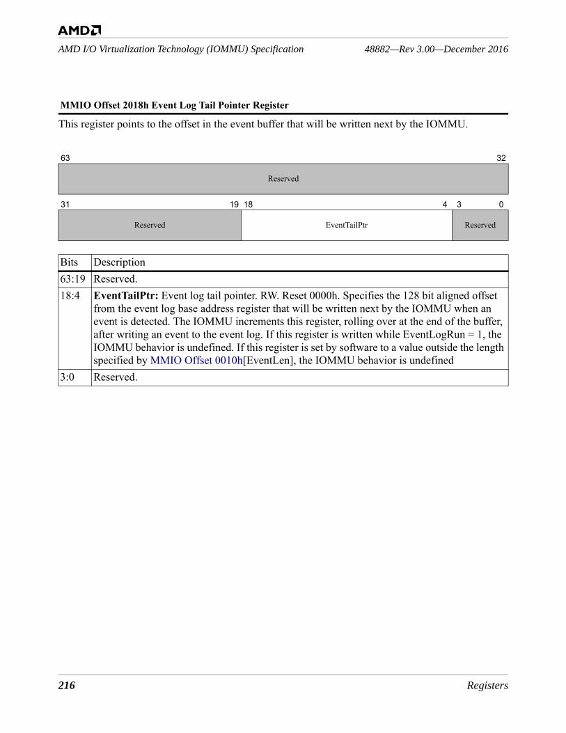
216 Registers
48882—Rev 3.00—December 2016AMD I/O Virtualization Technology (IOMMU) Specification
This register points to the offset in the event buffer that will be written next by the IOMMU.
MMIO Offset 2018h Event Log Tail Pointer Register
63 32
Reserved
31 19 18 4 3 0
Reserved EventTailPtr Reserved
Bits Description63:19 Reserved. 18:4 EventTailPtr: Event log tail pointer. RW. Reset 0000h. Specifies the 128 bit aligned offset
from the event log base address register that will be written next by the IOMMU when an event is detected. The IOMMU increments this register, rolling over at the end of the buffer, after writing an event to the event log. If this register is written while EventLogRun = 1, the IOMMU behavior is undefined. If this register is set by software to a value outside the length specified by MMIO Offset 0010h[EventLen], the IOMMU behavior is undefined
3:0 Reserved.
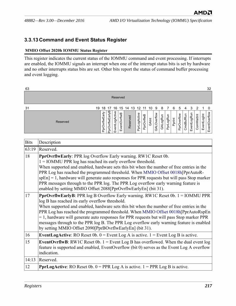
Registers 217
AMD I/O Virtualization Technology (IOMMU) Specification48882—Rev 3.00—December 2016
3.3.13 Command and Event Status Register
This register indicates the current status of the IOMMU command and event processing. If interrupts are enabled, the IOMMU signals an interrupt when one of the interrupt status bits is set by hardware and no other interrupts status bits are set. Other bits report the status of command buffer processing and event logging.
MMIO Offset 2020h IOMMU Status Register
63 32
Reserved
31 19 18 17 16 15 14 13 12 11 10 9 8 7 6 5 4 3 2 1 0
Reserved
PprO
vrflw
Early
PprO
vrflw
Early
B
Even
tLog
Activ
e
Even
tOvr
flwB
Res
erve
d
PprL
ogAc
tive
PprO
vrflw
B
GAI
nt
GAL
Ove
rflow
GAL
ogR
un
PprL
ogR
un
PprIn
t
PprO
verfl
ow
Cm
dBuf
Run
Even
tLog
Run
Com
Wai
tInt
Even
tLog
Int
Even
tOve
rflow
Bits Description63:19 Reserved. 18 PprOvrflwEarly: PPR log Overflow Early warning. RW1C Reset 0b.
1 = IOMMU PPR log has reached its early overflow threshold. When supported and enabled, hardware sets this bit when the number of free entries in the PPR Log has reached the programmed threshold. When MMIO Offset 0018h[PprAutoR-spEn] = 1, hardware will generate auto responses for PPR requests but will pass Stop marker PPR messages through to the PPR log. The PPR Log overflow early warning feature is enabled by setting MMIO Offset 2088[PprOvrflwEarlyEn] (bit 31).
17 PprOvrflwEarlyB: PPR log B Overflow Early warning. RW1C Reset 0b. 1 = IOMMU PPR log B has reached its early overflow threshold. When supported and enabled, hardware sets this bit when the number of free entries in the PPR Log has reached the programmed threshold. When MMIO Offset 0018h[PprAutoRspEn = 1, hardware will generate auto responses for PPR requests but will pass Stop marker PPR messages through to the PPR log B. The PPR Log overflow early warning feature is enabled by setting MMIO Offset 2090[PprBOvrflwEarlyEn] (bit 31).
16 EventLogActive: RO Reset 0b. 0 = Event Log A is active. 1 = Event Log B is active.15 EventOvrflwB: RW1C Reset 0b. 1 = Event Log B has overflowed. When the dual event log
feature is supported and enabled, EventOverflow (bit 0) serves as the Event Log A overflow indication.
14:13 Reserved. 12 PprLogActive: RO Reset 0b. 0 = PPR Log A is active. 1 = PPR Log B is active.
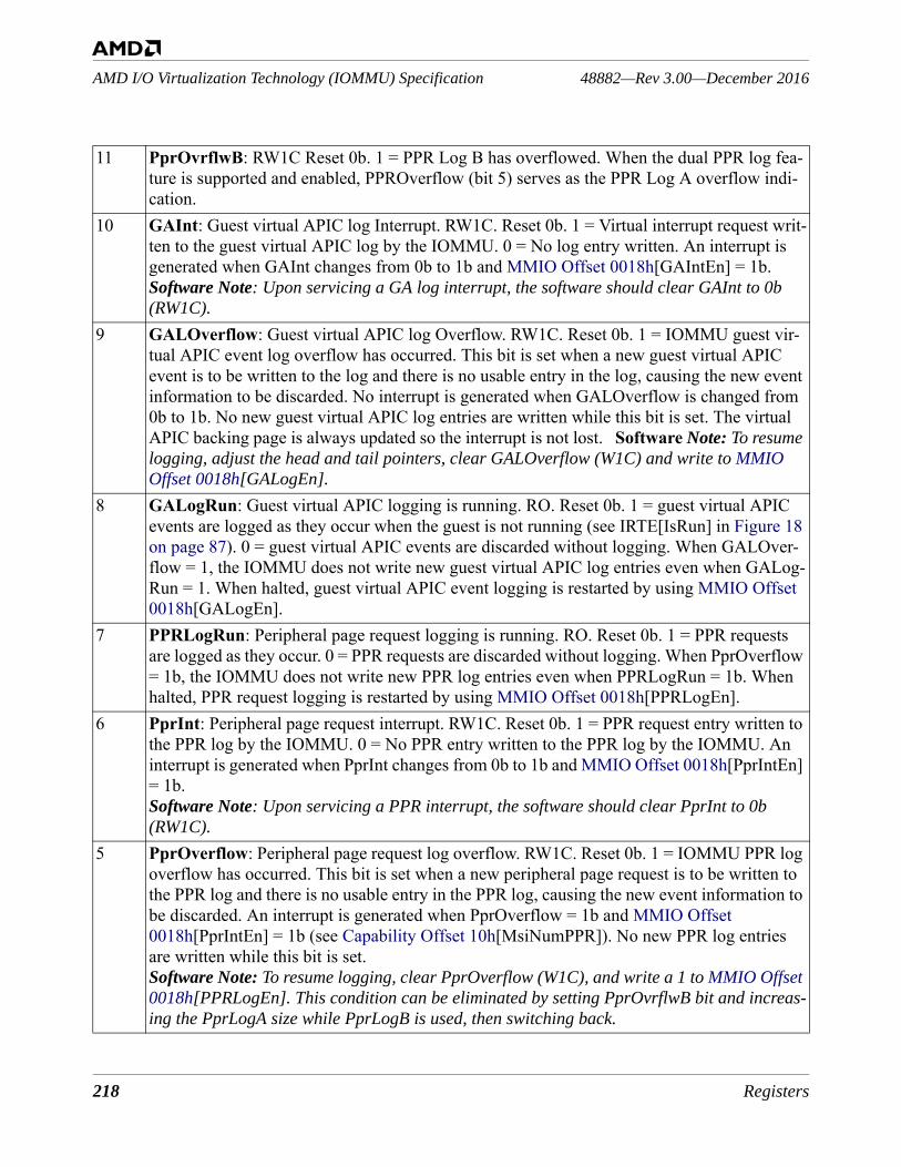
218 Registers
48882—Rev 3.00—December 2016AMD I/O Virtualization Technology (IOMMU) Specification
11 PprOvrflwB: RW1C Reset 0b. 1 = PPR Log B has overflowed. When the dual PPR log fea-ture is supported and enabled, PPROverflow (bit 5) serves as the PPR Log A overflow indi-cation.
10 GAInt: Guest virtual APIC log Interrupt. RW1C. Reset 0b. 1 = Virtual interrupt request writ-ten to the guest virtual APIC log by the IOMMU. 0 = No log entry written. An interrupt is generated when GAInt changes from 0b to 1b and MMIO Offset 0018h[GAIntEn] = 1b. Software Note: Upon servicing a GA log interrupt, the software should clear GAInt to 0b (RW1C).
9 GALOverflow: Guest virtual APIC log Overflow. RW1C. Reset 0b. 1 = IOMMU guest vir-tual APIC event log overflow has occurred. This bit is set when a new guest virtual APIC event is to be written to the log and there is no usable entry in the log, causing the new event information to be discarded. No interrupt is generated when GALOverflow is changed from 0b to 1b. No new guest virtual APIC log entries are written while this bit is set. The virtual APIC backing page is always updated so the interrupt is not lost. Software Note: To resume logging, adjust the head and tail pointers, clear GALOverflow (W1C) and write to MMIO Offset 0018h[GALogEn].
8 GALogRun: Guest virtual APIC logging is running. RO. Reset 0b. 1 = guest virtual APIC events are logged as they occur when the guest is not running (see IRTE[IsRun] in Figure 18 on page 87). 0 = guest virtual APIC events are discarded without logging. When GALOver-flow = 1, the IOMMU does not write new guest virtual APIC log entries even when GALog-Run = 1. When halted, guest virtual APIC event logging is restarted by using MMIO Offset 0018h[GALogEn].
7 PPRLogRun: Peripheral page request logging is running. RO. Reset 0b. 1 = PPR requests are logged as they occur. 0 = PPR requests are discarded without logging. When PprOverflow = 1b, the IOMMU does not write new PPR log entries even when PPRLogRun = 1b. When halted, PPR request logging is restarted by using MMIO Offset 0018h[PPRLogEn].
6 PprInt: Peripheral page request interrupt. RW1C. Reset 0b. 1 = PPR request entry written to the PPR log by the IOMMU. 0 = No PPR entry written to the PPR log by the IOMMU. An interrupt is generated when PprInt changes from 0b to 1b and MMIO Offset 0018h[PprIntEn] = 1b. Software Note: Upon servicing a PPR interrupt, the software should clear PprInt to 0b (RW1C).
5 PprOverflow: Peripheral page request log overflow. RW1C. Reset 0b. 1 = IOMMU PPR log overflow has occurred. This bit is set when a new peripheral page request is to be written to the PPR log and there is no usable entry in the PPR log, causing the new event information to be discarded. An interrupt is generated when PprOverflow = 1b and MMIO Offset 0018h[PprIntEn] = 1b (see Capability Offset 10h[MsiNumPPR]). No new PPR log entries are written while this bit is set.Software Note: To resume logging, clear PprOverflow (W1C), and write a 1 to MMIO Offset 0018h[PPRLogEn]. This condition can be eliminated by setting PprOvrflwB bit and increas-ing the PprLogA size while PprLogB is used, then switching back.
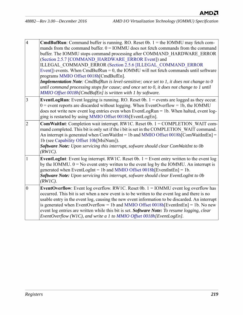
Registers 219
AMD I/O Virtualization Technology (IOMMU) Specification48882—Rev 3.00—December 2016
4 CmdBufRun: Command buffer is running. RO. Reset 0b. 1 = the IOMMU may fetch com-mands from the command buffer. 0 = IOMMU does not fetch commands from the command buffer. The IOMMU stops command processing after COMMAND_HARDWARE_ERROR (Section 2.5.7 [COMMAND_HARDWARE_ERROR Event]) and ILLEGAL_COMMAND_ERROR (Section 2.5.6 [ILLEGAL_COMMAND_ERROR Event]) events. When CmdBufRun = 0, the IOMMU will not fetch commands until software programs MMIO Offset 0018h[CmdBufEn].Implementation Note: CmdBufRun is level-sensitive; once set to 1, it does not change to 0 until command processing stops for cause; and once set to 0, it does not change to 1 until MMIO Offset 0018h[CmdBufEn] is written with 1 by software.
3 EventLogRun: Event logging is running. RO. Reset 0b. 1 = events are logged as they occur. 0 = event reports are discarded without logging. When EventOverflow = 1b, the IOMMU does not write new event log entries even when EventLogRun = 1b. When halted, event log-ging is restarted by using MMIO Offset 0018h[EventLogEn].
2 ComWaitInt: Completion wait interrupt. RW1C. Reset 0b. 1 = COMPLETION_WAIT com-mand completed. This bit is only set if the i bit is set in the COMPLETION_WAIT command. An interrupt is generated when ComWaitInt = 1b and MMIO Offset 0018h[ComWaitIntEn] = 1b (see Capability Offset 10h[MsiNum]).Software Note: Upon servicing this interrupt, sofware should clear ComWaitInt to 0b (RW1C).
1 EventLogInt: Event log interrupt. RW1C. Reset 0b. 1 = Event entry written to the event log by the IOMMU. 0 = No event entry written to the event log by the IOMMU. An interrupt is generated when EventLogInt = 1b and MMIO Offset 0018h[EventIntEn] = 1b.Software Note: Upon servicing this interrupt, sofware should clear EventLogInt to 0b (RW1C).
0 EventOverflow: Event log overflow. RW1C. Reset 0b. 1 = IOMMU event log overflow has occurred. This bit is set when a new event is to be written to the event log and there is no usable entry in the event log, causing the new event information to be discarded. An interrupt is generated when EventOverflow = 1b and MMIO Offset 0018h[EventIntEn] = 1b. No new event log entries are written while this bit is set. Software Note: To resume logging, clear EventOverflow (W1C), and write a 1 to MMIO Offset 0018h[EventLogEn].
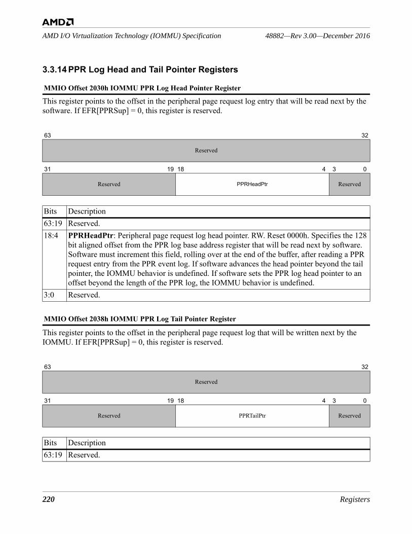
220 Registers
48882—Rev 3.00—December 2016AMD I/O Virtualization Technology (IOMMU) Specification
3.3.14 PPR Log Head and Tail Pointer Registers
This register points to the offset in the peripheral page request log entry that will be read next by the software. If EFR[PPRSup] = 0, this register is reserved.
This register points to the offset in the peripheral page request log that will be written next by the IOMMU. If EFR[PPRSup] = 0, this register is reserved.
MMIO Offset 2030h IOMMU PPR Log Head Pointer Register
63 32
Reserved
31 19 18 4 3 0
Reserved PPRHeadPtr Reserved
Bits Description63:19 Reserved. 18:4 PPRHeadPtr: Peripheral page request log head pointer. RW. Reset 0000h. Specifies the 128
bit aligned offset from the PPR log base address register that will be read next by software. Software must increment this field, rolling over at the end of the buffer, after reading a PPR request entry from the PPR event log. If software advances the head pointer beyond the tail pointer, the IOMMU behavior is undefined. If software sets the PPR log head pointer to an offset beyond the length of the PPR log, the IOMMU behavior is undefined.
3:0 Reserved.
MMIO Offset 2038h IOMMU PPR Log Tail Pointer Register
63 32
Reserved
31 19 18 4 3 0
Reserved PPRTailPtr Reserved
Bits Description63:19 Reserved.
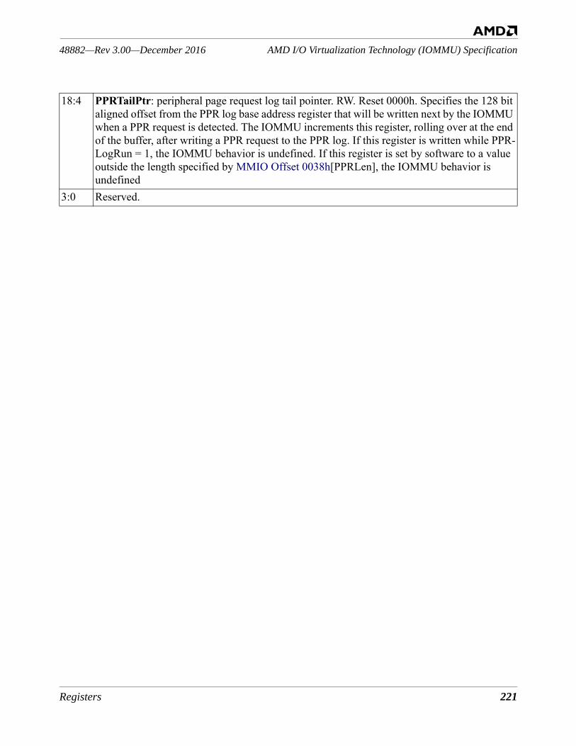
Registers 221
AMD I/O Virtualization Technology (IOMMU) Specification48882—Rev 3.00—December 2016
18:4 PPRTailPtr: peripheral page request log tail pointer. RW. Reset 0000h. Specifies the 128 bit aligned offset from the PPR log base address register that will be written next by the IOMMU when a PPR request is detected. The IOMMU increments this register, rolling over at the end of the buffer, after writing a PPR request to the PPR log. If this register is written while PPR-LogRun = 1, the IOMMU behavior is undefined. If this register is set by software to a value outside the length specified by MMIO Offset 0038h[PPRLen], the IOMMU behavior is undefined
3:0 Reserved.
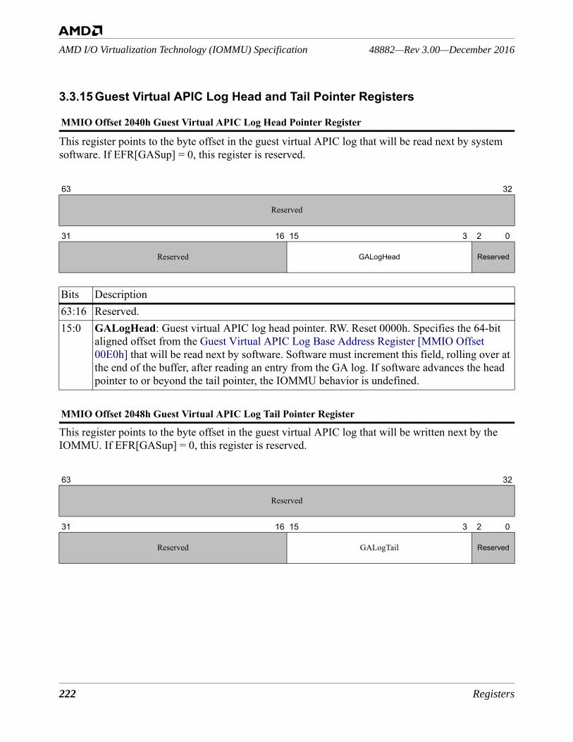
222 Registers
48882—Rev 3.00—December 2016AMD I/O Virtualization Technology (IOMMU) Specification
3.3.15 Guest Virtual APIC Log Head and Tail Pointer Registers
This register points to the byte offset in the guest virtual APIC log that will be read next by system software. If EFR[GASup] = 0, this register is reserved.
This register points to the byte offset in the guest virtual APIC log that will be written next by the IOMMU. If EFR[GASup] = 0, this register is reserved.
MMIO Offset 2040h Guest Virtual APIC Log Head Pointer Register
63 32
Reserved
31 16 15 3 2 0
Reserved GALogHead Reserved
Bits Description63:16 Reserved. 15:0 GALogHead: Guest virtual APIC log head pointer. RW. Reset 0000h. Specifies the 64-bit
aligned offset from the Guest Virtual APIC Log Base Address Register [MMIO Offset 00E0h] that will be read next by software. Software must increment this field, rolling over at the end of the buffer, after reading an entry from the GA log. If software advances the head pointer to or beyond the tail pointer, the IOMMU behavior is undefined.
MMIO Offset 2048h Guest Virtual APIC Log Tail Pointer Register
63 32
Reserved
31 16 15 3 2 0
Reserved GALogTail Reserved
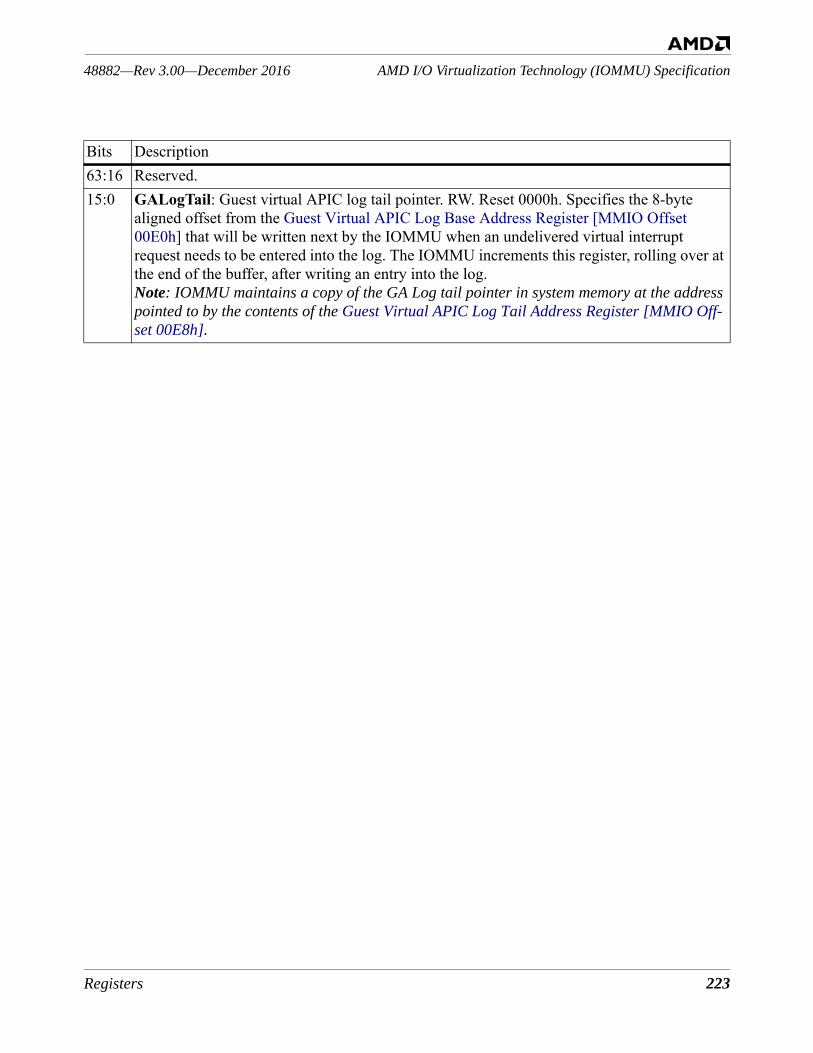
Registers 223
AMD I/O Virtualization Technology (IOMMU) Specification48882—Rev 3.00—December 2016
Bits Description63:16 Reserved. 15:0 GALogTail: Guest virtual APIC log tail pointer. RW. Reset 0000h. Specifies the 8-byte
aligned offset from the Guest Virtual APIC Log Base Address Register [MMIO Offset 00E0h] that will be written next by the IOMMU when an undelivered virtual interrupt request needs to be entered into the log. The IOMMU increments this register, rolling over at the end of the buffer, after writing an entry into the log.Note: IOMMU maintains a copy of the GA Log tail pointer in system memory at the address pointed to by the contents of the Guest Virtual APIC Log Tail Address Register [MMIO Off-set 00E8h].
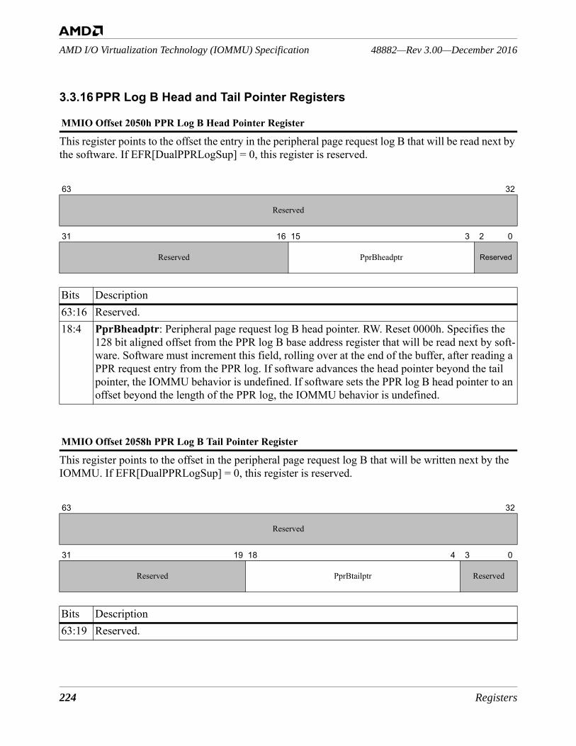
224 Registers
48882—Rev 3.00—December 2016AMD I/O Virtualization Technology (IOMMU) Specification
3.3.16 PPR Log B Head and Tail Pointer Registers
This register points to the offset the entry in the peripheral page request log B that will be read next by the software. If EFR[DualPPRLogSup] = 0, this register is reserved.
This register points to the offset in the peripheral page request log B that will be written next by the IOMMU. If EFR[DualPPRLogSup] = 0, this register is reserved.
MMIO Offset 2050h PPR Log B Head Pointer Register
63 32
Reserved
31 16 15 3 2 0
Reserved PprBheadptr Reserved
Bits Description63:16 Reserved. 18:4 PprBheadptr: Peripheral page request log B head pointer. RW. Reset 0000h. Specifies the
128 bit aligned offset from the PPR log B base address register that will be read next by soft-ware. Software must increment this field, rolling over at the end of the buffer, after reading a PPR request entry from the PPR log. If software advances the head pointer beyond the tail pointer, the IOMMU behavior is undefined. If software sets the PPR log B head pointer to an offset beyond the length of the PPR log, the IOMMU behavior is undefined.
MMIO Offset 2058h PPR Log B Tail Pointer Register
63 32
Reserved
31 19 18 4 3 0
Reserved PprBtailptr Reserved
Bits Description63:19 Reserved.
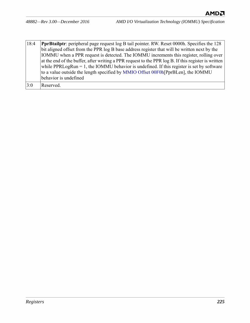
Registers 225
AMD I/O Virtualization Technology (IOMMU) Specification48882—Rev 3.00—December 2016
18:4 PprBtailptr: peripheral page request log B tail pointer. RW. Reset 0000h. Specifies the 128 bit aligned offset from the PPR log B base address register that will be written next by the IOMMU when a PPR request is detected. The IOMMU increments this register, rolling over at the end of the buffer, after writing a PPR request to the PPR log B. If this register is written while PPRLogRun = 1, the IOMMU behavior is undefined. If this register is set by software to a value outside the length specified by MMIO Offset 00F0h[PprBLen], the IOMMU behavior is undefined
3:0 Reserved.

226 Registers
48882—Rev 3.00—December 2016AMD I/O Virtualization Technology (IOMMU) Specification
3.3.17 Event Log B Head and Tail Pointer Registers
This register points to the offset in the event log B that will be read next by the software. If EFR[DualEventLogSup] = 0, this register is reserved.
This register points to the offset in the event Log B buffer that will be written next by the IOMMU. If EFR[DualEventLogSup] = 0, this register is reserved.
MMIO Offset 2070h Event Log B Head Pointer Register
63 32
Reserved
31 16 15 3 2 0
Reserved EventLogBheadptr Reserved
Bits Description63:16 Reserved. 18:4 EventLogBheadptr: Event log B head pointer. RW. Reset 0000h. Specifies the 128 bit
aligned offset from the Event Log B base address register that will be read next by software. Software must increment this field, rolling over at the end of the buffer, after reading an event log entry from the Event log B. If software advances the head pointer beyond the tail pointer, the IOMMU behavior is undefined. If software sets the Event log B head pointer to an offset beyond the length of the Event log B, the IOMMU behavior is undefined.
MMIO Offset 2078h Event Log B Tail Pointer Register
63 32
Reserved
31 19 18 4 3 0
Reserved EventLogBtailptr Reserved
Bits Description63:19 Reserved.
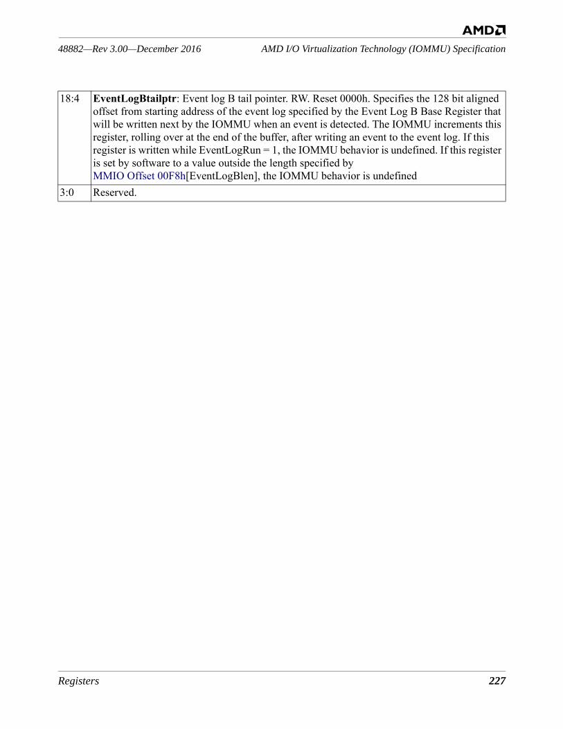
Registers 227
AMD I/O Virtualization Technology (IOMMU) Specification48882—Rev 3.00—December 2016
18:4 EventLogBtailptr: Event log B tail pointer. RW. Reset 0000h. Specifies the 128 bit aligned offset from starting address of the event log specified by the Event Log B Base Register that will be written next by the IOMMU when an event is detected. The IOMMU increments this register, rolling over at the end of the buffer, after writing an event to the event log. If this register is written while EventLogRun = 1, the IOMMU behavior is undefined. If this register is set by software to a value outside the length specified by MMIO Offset 00F8h[EventLogBlen], the IOMMU behavior is undefined
3:0 Reserved.
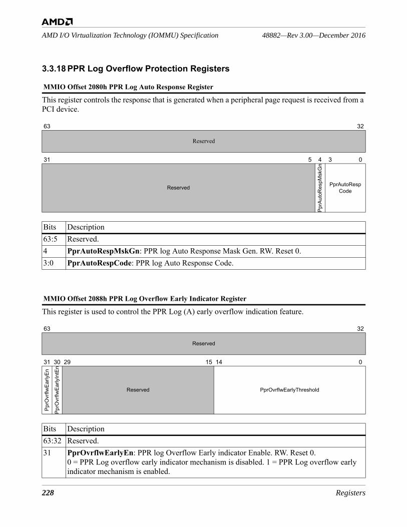
228 Registers
48882—Rev 3.00—December 2016AMD I/O Virtualization Technology (IOMMU) Specification
3.3.18 PPR Log Overflow Protection Registers
This register controls the response that is generated when a peripheral page request is received from a PCI device.
This register is used to control the PPR Log (A) early overflow indication feature.
MMIO Offset 2080h PPR Log Auto Response Register
63 32
Reserved
31 5 4 3 0
Reserved
PprA
utoR
espM
skG
n
PprAutoRespCode
Bits Description63:5 Reserved. 4 PprAutoRespMskGn: PPR log Auto Response Mask Gen. RW. Reset 0. 3:0 PprAutoRespCode: PPR log Auto Response Code.
MMIO Offset 2088h PPR Log Overflow Early Indicator Register
63 32
Reserved
31 30 29 15 14 0
PprO
vrflw
Early
En
PprO
vrflw
Early
IntE
n
Reserved PprOvrflwEarlyThreshold
Bits Description63:32 Reserved. 31 PprOvrflwEarlyEn: PPR log Overflow Early indicator Enable. RW. Reset 0.
0 = PPR Log overflow early indicator mechanism is disabled. 1 = PPR Log overflow early indicator mechanism is enabled.
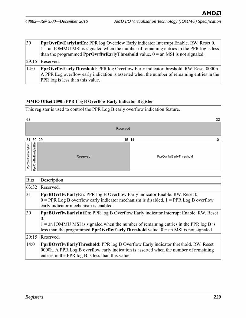
Registers 229
AMD I/O Virtualization Technology (IOMMU) Specification48882—Rev 3.00—December 2016
This register is used to control the PPR Log B early overflow indication feature.
30 PprOvrflwEarlyIntEn: PPR log Overflow Early indicator Interrupt Enable. RW. Reset 0. 1 = an IOMMU MSI is signaled when the number of remaining entries in the PPR log is less than the programmed PprOvrflwEarlyThreshold value. 0 = an MSI is not signaled.
29:15 Reserved.14:0 PprOvrflwEarlyThreshold: PPR log Overflow Early indicator threshold. RW. Reset 0000h.
A PPR Log overflow early indication is asserted when the number of remaining entries in the PPR log is less than this value.
MMIO Offset 2090h PPR Log B Overflow Early Indicator Register
63 32
Reserved
31 30 29 15 14 0
PprO
vrflw
Early
En
PprO
vrflw
Early
IntE
n
Reserved PprOvrflwEarlyThreshold
Bits Description63:32 Reserved. 31 PprBOvrflwEarlyEn: PPR log B Overflow Early indicator Enable. RW. Reset 0.
0 = PPR Log B overflow early indicator mechanism is disabled. 1 = PPR Log B overflow early indicator mechanism is enabled.
30 PprBOvrflwEarlyIntEn: PPR log B Overflow Early indicator Interrupt Enable. RW. Reset 0.1 = an IOMMU MSI is signaled when the number of remaining entries in the PPR log B is less than the programmed PprOvrflwEarlyThreshold value. 0 = an MSI is not signaled.
29:15 Reserved.14:0 PprBOvrflwEarlyThreshold: PPR log B Overflow Early indicator threshold. RW. Reset
0000h. A PPR Log B overflow early indication is asserted when the number of remaining entries in the PPR log B is less than this value.
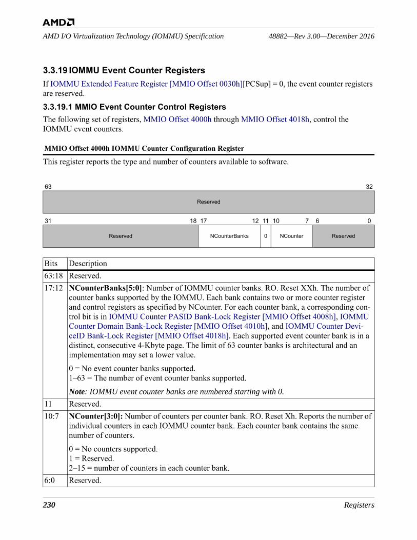
230 Registers
48882—Rev 3.00—December 2016AMD I/O Virtualization Technology (IOMMU) Specification
3.3.19 IOMMU Event Counter RegistersIf IOMMU Extended Feature Register [MMIO Offset 0030h][PCSup] = 0, the event counter registers are reserved.3.3.19.1 MMIO Event Counter Control RegistersThe following set of registers, MMIO Offset 4000h through MMIO Offset 4018h, control the IOMMU event counters.
This register reports the type and number of counters available to software.
MMIO Offset 4000h IOMMU Counter Configuration Register
63 32
Reserved
31 18 17 12 11 10 7 6 0
Reserved NCounterBanks 0 NCounter Reserved
Bits Description63:18 Reserved.17:12 NCounterBanks[5:0]: Number of IOMMU counter banks. RO. Reset XXh. The number of
counter banks supported by the IOMMU. Each bank contains two or more counter register and control registers as specified by NCounter. For each counter bank, a corresponding con-trol bit is in IOMMU Counter PASID Bank-Lock Register [MMIO Offset 4008h], IOMMU Counter Domain Bank-Lock Register [MMIO Offset 4010h], and IOMMU Counter Devi-ceID Bank-Lock Register [MMIO Offset 4018h]. Each supported event counter bank is in a distinct, consecutive 4-Kbyte page. The limit of 63 counter banks is architectural and an implementation may set a lower value. 0 = No event counter banks supported.1–63 = The number of event counter banks supported.Note: IOMMU event counter banks are numbered starting with 0.
11 Reserved.10:7 NCounter[3:0]: Number of counters per counter bank. RO. Reset Xh. Reports the number of
individual counters in each IOMMU counter bank. Each counter bank contains the same number of counters.0 = No counters supported.1 = Reserved.2–15 = number of counters in each counter bank.
6:0 Reserved.
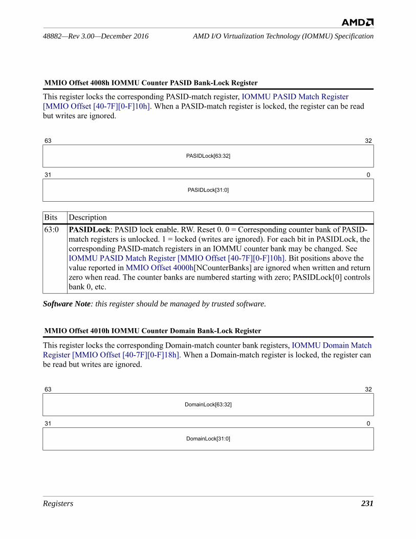
Registers 231
AMD I/O Virtualization Technology (IOMMU) Specification48882—Rev 3.00—December 2016
This register locks the corresponding PASID-match register, IOMMU PASID Match Register [MMIO Offset [40-7F][0-F]10h]. When a PASID-match register is locked, the register can be read but writes are ignored.
Software Note: this register should be managed by trusted software.
This register locks the corresponding Domain-match counter bank registers, IOMMU Domain Match Register [MMIO Offset [40-7F][0-F]18h]. When a Domain-match register is locked, the register can be read but writes are ignored.
MMIO Offset 4008h IOMMU Counter PASID Bank-Lock Register
63 32
PASIDLock[63:32]
31 0
PASIDLock[31:0]
Bits Description63:0 PASIDLock: PASID lock enable. RW. Reset 0. 0 = Corresponding counter bank of PASID-
match registers is unlocked. 1 = locked (writes are ignored). For each bit in PASIDLock, the corresponding PASID-match registers in an IOMMU counter bank may be changed. See IOMMU PASID Match Register [MMIO Offset [40-7F][0-F]10h]. Bit positions above the value reported in MMIO Offset 4000h[NCounterBanks] are ignored when written and return zero when read. The counter banks are numbered starting with zero; PASIDLock[0] controls bank 0, etc.
MMIO Offset 4010h IOMMU Counter Domain Bank-Lock Register
63 32
DomainLock[63:32]
31 0
DomainLock[31:0]
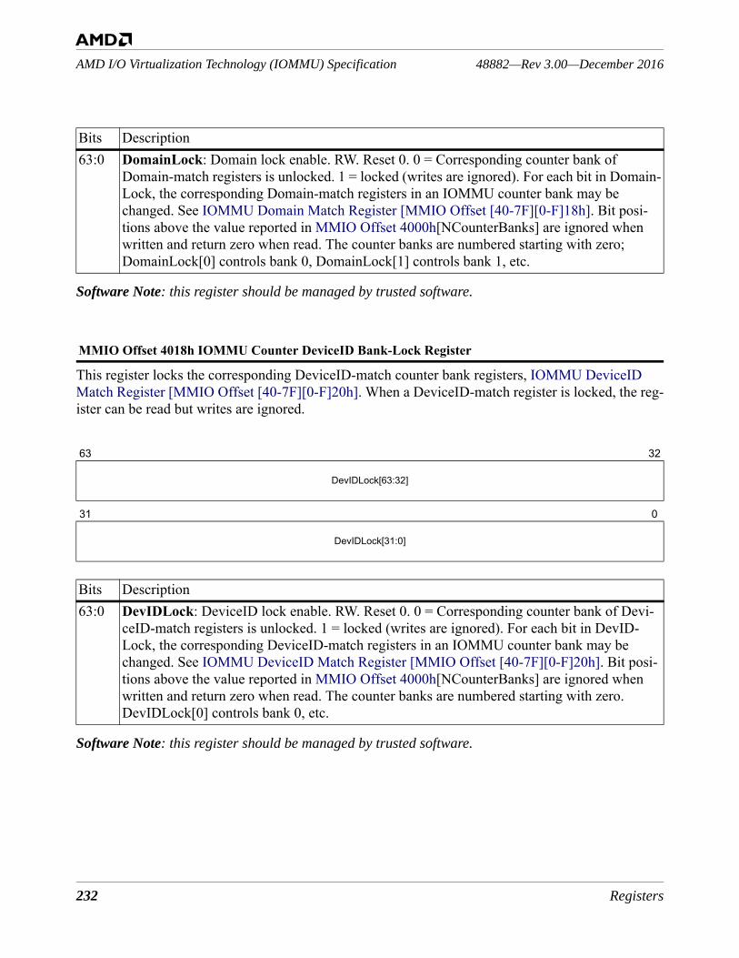
232 Registers
48882—Rev 3.00—December 2016AMD I/O Virtualization Technology (IOMMU) Specification
Software Note: this register should be managed by trusted software.
This register locks the corresponding DeviceID-match counter bank registers, IOMMU DeviceID Match Register [MMIO Offset [40-7F][0-F]20h]. When a DeviceID-match register is locked, the reg-ister can be read but writes are ignored.
Software Note: this register should be managed by trusted software.
Bits Description63:0 DomainLock: Domain lock enable. RW. Reset 0. 0 = Corresponding counter bank of
Domain-match registers is unlocked. 1 = locked (writes are ignored). For each bit in Domain-Lock, the corresponding Domain-match registers in an IOMMU counter bank may be changed. See IOMMU Domain Match Register [MMIO Offset [40-7F][0-F]18h]. Bit posi-tions above the value reported in MMIO Offset 4000h[NCounterBanks] are ignored when written and return zero when read. The counter banks are numbered starting with zero; DomainLock[0] controls bank 0, DomainLock[1] controls bank 1, etc.
MMIO Offset 4018h IOMMU Counter DeviceID Bank-Lock Register
63 32
DevIDLock[63:32]
31 0
DevIDLock[31:0]
Bits Description63:0 DevIDLock: DeviceID lock enable. RW. Reset 0. 0 = Corresponding counter bank of Devi-
ceID-match registers is unlocked. 1 = locked (writes are ignored). For each bit in DevID-Lock, the corresponding DeviceID-match registers in an IOMMU counter bank may be changed. See IOMMU DeviceID Match Register [MMIO Offset [40-7F][0-F]20h]. Bit posi-tions above the value reported in MMIO Offset 4000h[NCounterBanks] are ignored when written and return zero when read. The counter banks are numbered starting with zero.DevIDLock[0] controls bank 0, etc.
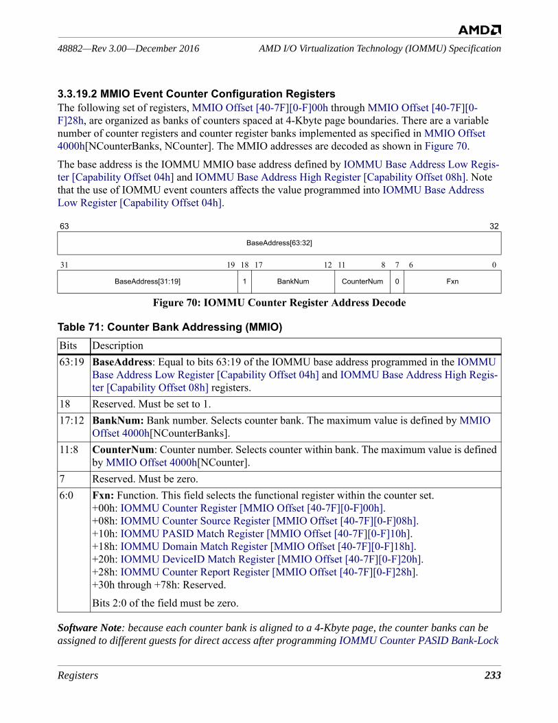
Registers 233
AMD I/O Virtualization Technology (IOMMU) Specification48882—Rev 3.00—December 2016
3.3.19.2 MMIO Event Counter Configuration RegistersThe following set of registers, MMIO Offset [40-7F][0-F]00h through MMIO Offset [40-7F][0-F]28h, are organized as banks of counters spaced at 4-Kbyte page boundaries. There are a variable number of counter registers and counter register banks implemented as specified in MMIO Offset 4000h[NCounterBanks, NCounter]. The MMIO addresses are decoded as shown in Figure 70.The base address is the IOMMU MMIO base address defined by IOMMU Base Address Low Regis-ter [Capability Offset 04h] and IOMMU Base Address High Register [Capability Offset 08h]. Note that the use of IOMMU event counters affects the value programmed into IOMMU Base Address Low Register [Capability Offset 04h].
Figure 70: IOMMU Counter Register Address Decode
Software Note: because each counter bank is aligned to a 4-Kbyte page, the counter banks can be assigned to different guests for direct access after programming IOMMU Counter PASID Bank-Lock
63 32
BaseAddress[63:32]
31 19 18 17 12 11 8 7 6 0
BaseAddress[31:19] 1 BankNum CounterNum 0 Fxn
Table 71: Counter Bank Addressing (MMIO)Bits Description63:19 BaseAddress: Equal to bits 63:19 of the IOMMU base address programmed in the IOMMU
Base Address Low Register [Capability Offset 04h] and IOMMU Base Address High Regis-ter [Capability Offset 08h] registers.
18 Reserved. Must be set to 1.17:12 BankNum: Bank number. Selects counter bank. The maximum value is defined by MMIO
Offset 4000h[NCounterBanks].11:8 CounterNum: Counter number. Selects counter within bank. The maximum value is defined
by MMIO Offset 4000h[NCounter].7 Reserved. Must be zero.6:0 Fxn: Function. This field selects the functional register within the counter set.
+00h: IOMMU Counter Register [MMIO Offset [40-7F][0-F]00h].+08h: IOMMU Counter Source Register [MMIO Offset [40-7F][0-F]08h].+10h: IOMMU PASID Match Register [MMIO Offset [40-7F][0-F]10h].+18h: IOMMU Domain Match Register [MMIO Offset [40-7F][0-F]18h].+20h: IOMMU DeviceID Match Register [MMIO Offset [40-7F][0-F]20h].+28h: IOMMU Counter Report Register [MMIO Offset [40-7F][0-F]28h].+30h through +78h: Reserved.Bits 2:0 of the field must be zero.
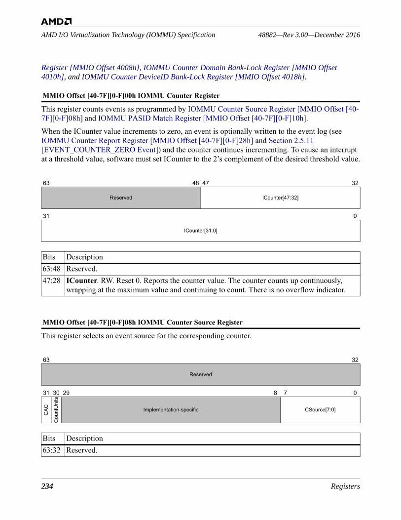
234 Registers
48882—Rev 3.00—December 2016AMD I/O Virtualization Technology (IOMMU) Specification
Register [MMIO Offset 4008h], IOMMU Counter Domain Bank-Lock Register [MMIO Offset 4010h], and IOMMU Counter DeviceID Bank-Lock Register [MMIO Offset 4018h].
This register counts events as programmed by IOMMU Counter Source Register [MMIO Offset [40-7F][0-F]08h] and IOMMU PASID Match Register [MMIO Offset [40-7F][0-F]10h].When the ICounter value increments to zero, an event is optionally written to the event log (see IOMMU Counter Report Register [MMIO Offset [40-7F][0-F]28h] and Section 2.5.11 [EVENT_COUNTER_ZERO Event]) and the counter continues incrementing. To cause an interrupt at a threshold value, software must set ICounter to the 2’s complement of the desired threshold value.
This register selects an event source for the corresponding counter.
MMIO Offset [40-7F][0-F]00h IOMMU Counter Register
63 48 47 32
Reserved ICounter[47:32]
31 0
ICounter[31:0]
Bits Description63:48 Reserved.47:28 ICounter. RW. Reset 0. Reports the counter value. The counter counts up continuously,
wrapping at the maximum value and continuing to count. There is no overflow indicator.
MMIO Offset [40-7F][0-F]08h IOMMU Counter Source Register
63 32
Reserved
31 30 29 8 7 0
CAC
Cou
ntU
nits
Implementation-specific CSource[7:0]
Bits Description63:32 Reserved.
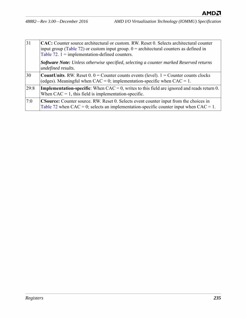
Registers 235
AMD I/O Virtualization Technology (IOMMU) Specification48882—Rev 3.00—December 2016
31 CAC: Counter source architectural or custom. RW. Reset 0. Selects architectural counter input group (Table 72) or custom input group. 0 = architectural counters as defined in Table 72. 1 = implementation-defined counters.Software Note: Unless otherwise specified, selecting a counter marked Reserved returns undefined results.
30 CountUnits. RW. Reset 0. 0 = Counter counts events (level). 1 = Counter counts clocks (edges). Meaningful when CAC = 0; implementation-specific when CAC = 1.
29:8 Implementation-specific: When CAC = 0, writes to this field are ignored and reads return 0. When CAC = 1, this field is implementation-specific.
7:0 CSource: Counter source. RW. Reset 0. Selects event counter input from the choices in Table 72 when CAC = 0; selects an implementation-specific counter input when CAC = 1.
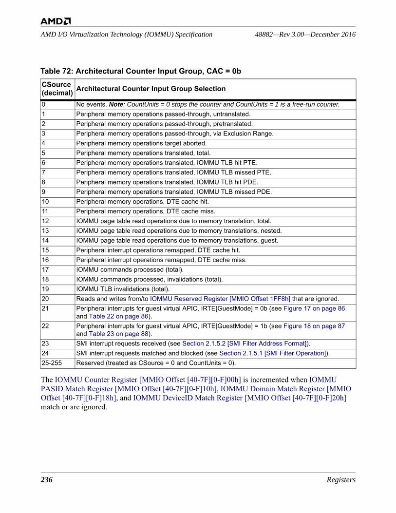
236 Registers
48882—Rev 3.00—December 2016AMD I/O Virtualization Technology (IOMMU) Specification
The IOMMU Counter Register [MMIO Offset [40-7F][0-F]00h] is incremented when IOMMU PASID Match Register [MMIO Offset [40-7F][0-F]10h], IOMMU Domain Match Register [MMIO Offset [40-7F][0-F]18h], and IOMMU DeviceID Match Register [MMIO Offset [40-7F][0-F]20h] match or are ignored.
Table 72: Architectural Counter Input Group, CAC = 0bCSource(decimal) Architectural Counter Input Group Selection
0 No events. Note: CountUnits = 0 stops the counter and CountUnits = 1 is a free-run counter.1 Peripheral memory operations passed-through, untranslated.2 Peripheral memory operations passed-through, pretranslated.3 Peripheral memory operations passed-through, via Exclusion Range.4 Peripheral memory operations target aborted.5 Peripheral memory operations translated, total.6 Peripheral memory operations translated, IOMMU TLB hit PTE.7 Peripheral memory operations translated, IOMMU TLB missed PTE.8 Peripheral memory operations translated, IOMMU TLB hit PDE.9 Peripheral memory operations translated, IOMMU TLB missed PDE.10 Peripheral memory operations, DTE cache hit.11 Peripheral memory operations, DTE cache miss.12 IOMMU page table read operations due to memory translation, total.13 IOMMU page table read operations due to memory translations, nested.14 IOMMU page table read operations due to memory translations, guest.15 Peripheral interrupt operations remapped, DTE cache hit.16 Peripheral interrupt operations remapped, DTE cache miss.17 IOMMU commands processed (total).18 IOMMU commands processed, invalidations (total).19 IOMMU TLB invalidations (total).20 Reads and writes from/to IOMMU Reserved Register [MMIO Offset 1FF8h] that are ignored. 21 Peripheral interrupts for guest virtual APIC, IRTE[GuestMode] = 0b (see Figure 17 on page 86
and Table 22 on page 86).22 Peripheral interrupts for guest virtual APIC, IRTE[GuestMode] = 1b (see Figure 18 on page 87
and Table 23 on page 88).23 SMI interrupt requests received (see Section 2.1.5.2 [SMI Filter Address Format]).24 SMI interrupt requests matched and blocked (see Section 2.1.5.1 [SMI Filter Operation]).25-255 Reserved (treated as CSource = 0 and CountUnits = 0).
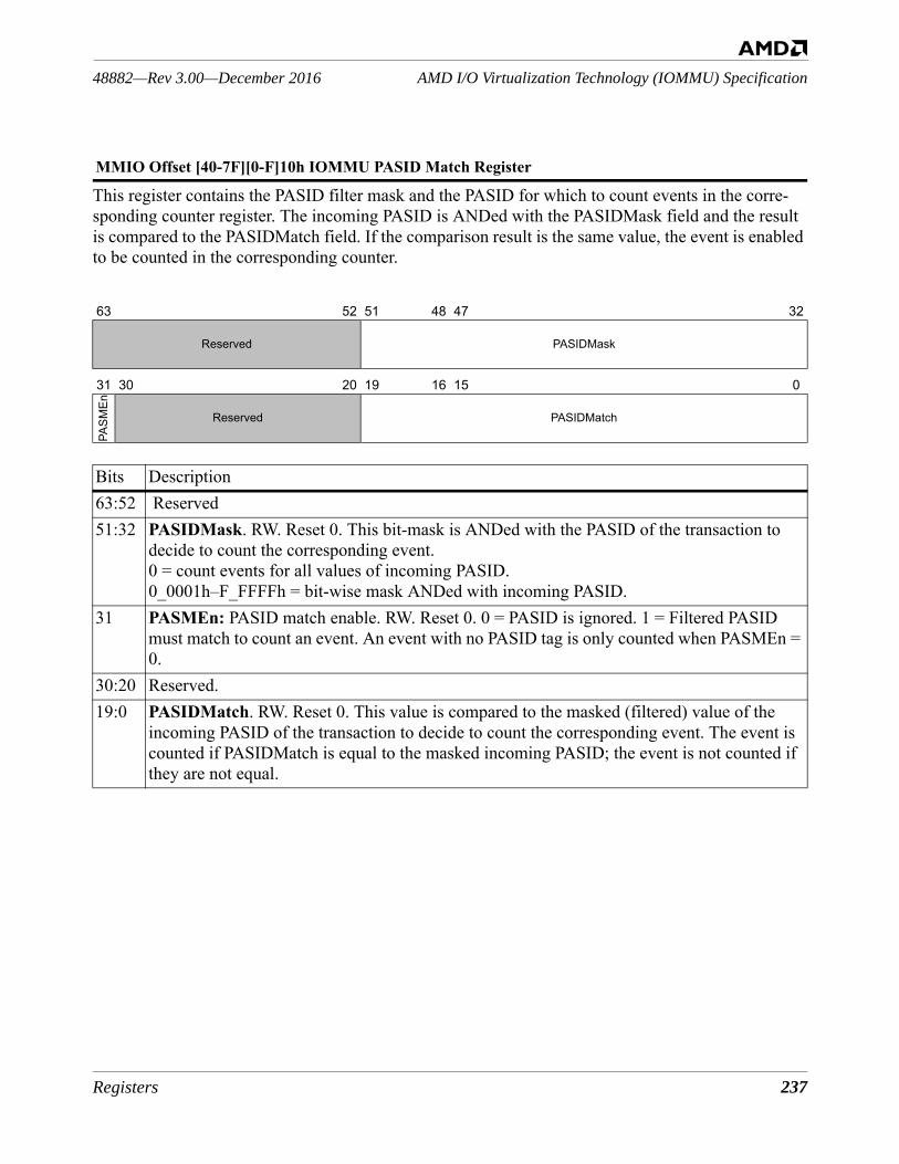
Registers 237
AMD I/O Virtualization Technology (IOMMU) Specification48882—Rev 3.00—December 2016
This register contains the PASID filter mask and the PASID for which to count events in the corre-sponding counter register. The incoming PASID is ANDed with the PASIDMask field and the result is compared to the PASIDMatch field. If the comparison result is the same value, the event is enabled to be counted in the corresponding counter.
MMIO Offset [40-7F][0-F]10h IOMMU PASID Match Register
63 52 51 48 47 32
Reserved PASIDMask
31 30 20 19 16 15 0
PASM
En
Reserved PASIDMatch
Bits Description63:52 Reserved51:32 PASIDMask. RW. Reset 0. This bit-mask is ANDed with the PASID of the transaction to
decide to count the corresponding event. 0 = count events for all values of incoming PASID. 0_0001h–F_FFFFh = bit-wise mask ANDed with incoming PASID.
31 PASMEn: PASID match enable. RW. Reset 0. 0 = PASID is ignored. 1 = Filtered PASID must match to count an event. An event with no PASID tag is only counted when PASMEn = 0.
30:20 Reserved.19:0 PASIDMatch. RW. Reset 0. This value is compared to the masked (filtered) value of the
incoming PASID of the transaction to decide to count the corresponding event. The event is counted if PASIDMatch is equal to the masked incoming PASID; the event is not counted if they are not equal.
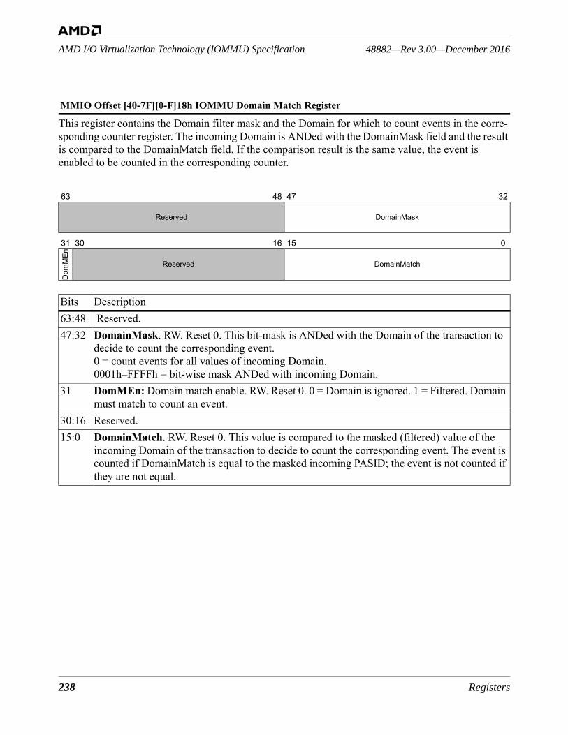
238 Registers
48882—Rev 3.00—December 2016AMD I/O Virtualization Technology (IOMMU) Specification
This register contains the Domain filter mask and the Domain for which to count events in the corre-sponding counter register. The incoming Domain is ANDed with the DomainMask field and the result is compared to the DomainMatch field. If the comparison result is the same value, the event is enabled to be counted in the corresponding counter.
MMIO Offset [40-7F][0-F]18h IOMMU Domain Match Register
63 48 47 32
Reserved DomainMask
31 30 16 15 0
Dom
MEn
Reserved DomainMatch
Bits Description63:48 Reserved.47:32 DomainMask. RW. Reset 0. This bit-mask is ANDed with the Domain of the transaction to
decide to count the corresponding event. 0 = count events for all values of incoming Domain. 0001h–FFFFh = bit-wise mask ANDed with incoming Domain.
31 DomMEn: Domain match enable. RW. Reset 0. 0 = Domain is ignored. 1 = Filtered. Domain must match to count an event.
30:16 Reserved.15:0 DomainMatch. RW. Reset 0. This value is compared to the masked (filtered) value of the
incoming Domain of the transaction to decide to count the corresponding event. The event is counted if DomainMatch is equal to the masked incoming PASID; the event is not counted if they are not equal.
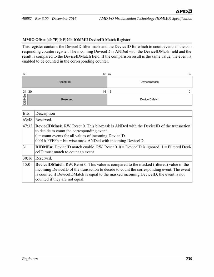
Registers 239
AMD I/O Virtualization Technology (IOMMU) Specification48882—Rev 3.00—December 2016
This register contains the DeviceID filter mask and the DeviceID for which to count events in the cor-responding counter register. The incoming DeviceID is ANDed with the DeviceIDMask field and the result is compared to the DeviceIDMatch field. If the comparison result is the same value, the event is enabled to be counted in the corresponding counter.
MMIO Offset [40-7F][0-F]20h IOMMU DeviceID Match Register
63 48 47 32
Reserved DeviceIDMask
31 30 16 15 0
DID
MEn
Reserved DeviceIDMatch
Bits Description63:48 Reserved.47:32 DeviceIDMask. RW. Reset 0. This bit-mask is ANDed with the DeviceID of the transaction
to decide to count the corresponding event. 0 = count events for all values of incoming DeviceID. 0001h-FFFFh = bit-wise mask ANDed with incoming DeviceID.
31 DIDMEn: DeviceID match enable. RW. Reset 0. 0 = DeviceID is ignored. 1 = Filtered Devi-ceID must match to count an event.
30:16 Reserved.15:0 DeviceIDMatch. RW. Reset 0. This value is compared to the masked (filtered) value of the
incoming DeviceID of the transaction to decide to count the corresponding event. The event is counted if DeviceIDMatch is equal to the masked incoming DeviceID; the event is not counted if they are not equal.
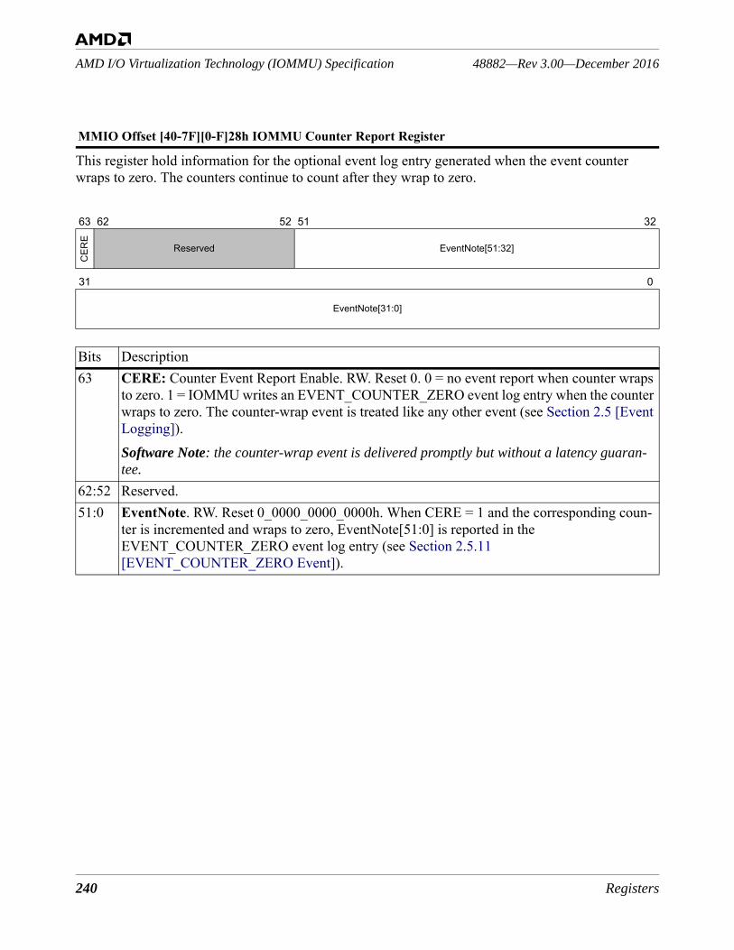
240 Registers
48882—Rev 3.00—December 2016AMD I/O Virtualization Technology (IOMMU) Specification
This register hold information for the optional event log entry generated when the event counter wraps to zero. The counters continue to count after they wrap to zero.
MMIO Offset [40-7F][0-F]28h IOMMU Counter Report Register
63 62 52 51 32
CER
E
Reserved EventNote[51:32]
31 0
EventNote[31:0]
Bits Description63 CERE: Counter Event Report Enable. RW. Reset 0. 0 = no event report when counter wraps
to zero. 1 = IOMMU writes an EVENT_COUNTER_ZERO event log entry when the counter wraps to zero. The counter-wrap event is treated like any other event (see Section 2.5 [Event Logging]). Software Note: the counter-wrap event is delivered promptly but without a latency guaran-tee.
62:52 Reserved.51:0 EventNote. RW. Reset 0_0000_0000_0000h. When CERE = 1 and the corresponding coun-
ter is incremented and wraps to zero, EventNote[51:0] is reported in the EVENT_COUNTER_ZERO event log entry (see Section 2.5.11 [EVENT_COUNTER_ZERO Event]).

Implementation Considerations 241
AMD I/O Virtualization Technology (IOMMU) Specification48882—Rev 3.00—December 2016
4 Implementation Considerations
This chapter discusses issues that are primarily of concern to IOMMU implementers.The IOMMU specification is intended to allow a wide range of implementations with different cost and performance trade-offs. Potential implementation technology may range from ASIC to full cus-tom. Capacity and organization of the IOMMU’s translation caches can vary substantially depending on technology, die budgets, and product requirements. The IOMMU can be integrated with a chipset (typically as part of some existing HyperTransport™ bridge) or built as a standalone component (which can act as a HyperTransport™ bridge or tunnel).
4.1 Caching and Invalidation StrategiesAll IOMMU implementations should have some form of translation cache that allows the IOMMU to determine the disposition of device accesses quickly without having to re-walk the IOMMU tables for each separate device access. The translation cache is likely to be the largest portion of the IOMMU’s die area budget in all but the smallest implementations. Consequently the IOMMU specification has been written to allow flexibility in the design of the translation cache.Plausible implementations range from direct mapped RAM structures to fully associative CAM struc-tures, with the expectation that most implementations are set associative. Furthermore, implementers may choose to flatten the multi-stage IOMMU table walk into a single cache array lookup, or, alterna-tively, may choose to use a similar multi-stage organization for internal translation cache lookups.The IOMMU’s translation cache must support the following operations:• Lookup — when the IOMMU processes an access by a particular device to a specified DVA, it
applies protection checks and translation transformations using information obtained using DeviceID and DVA.
• Invalidate device — discard any translation cache contents that depend on a specific Device Table entry.
• Invalidate virtual address (within domain) — discard any cached translations for a virtual address within the specified domain.
Typical IOMMU implementations are likely to be built with ASIC design flows, where CAM cells are expensive compared to RAM cells. The main implication of this is that direct support for different page sizes is likely to require a combination of separate arrays and/or multiple entries within arrays, causing both fills and invalidations to require time-consuming search-and-destroy algorithms. The IOMMU is designed to support three main usage models: • Direct user process access to a single device like a graphics controller; • Direct virtual machine guest access to a collection of devices that have been dedicated to that
guest; and • A single non-virtualized OS using the IOMMU to enforce device to system memory access
controls.
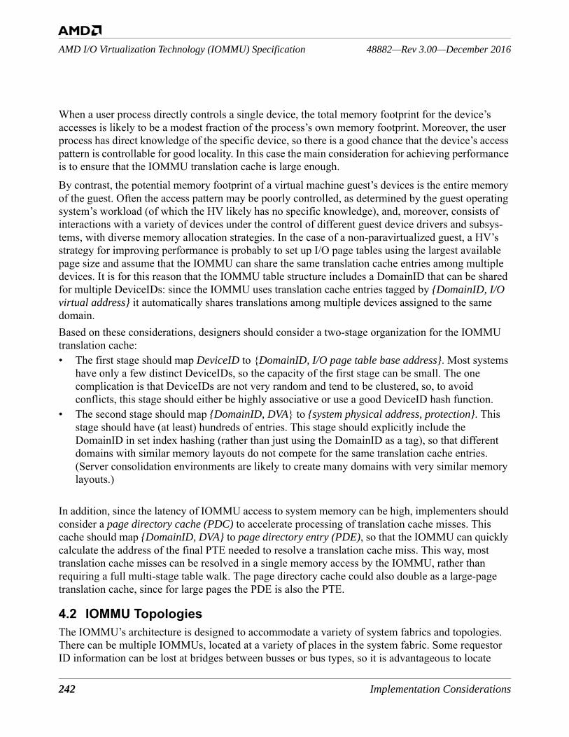
242 Implementation Considerations
48882—Rev 3.00—December 2016AMD I/O Virtualization Technology (IOMMU) Specification
When a user process directly controls a single device, the total memory footprint for the device’s accesses is likely to be a modest fraction of the process’s own memory footprint. Moreover, the user process has direct knowledge of the specific device, so there is a good chance that the device’s access pattern is controllable for good locality. In this case the main consideration for achieving performance is to ensure that the IOMMU translation cache is large enough.By contrast, the potential memory footprint of a virtual machine guest’s devices is the entire memory of the guest. Often the access pattern may be poorly controlled, as determined by the guest operating system’s workload (of which the HV likely has no specific knowledge), and, moreover, consists of interactions with a variety of devices under the control of different guest device drivers and subsys-tems, with diverse memory allocation strategies. In the case of a non-paravirtualized guest, a HV’s strategy for improving performance is probably to set up I/O page tables using the largest available page size and assume that the IOMMU can share the same translation cache entries among multiple devices. It is for this reason that the IOMMU table structure includes a DomainID that can be shared for multiple DeviceIDs: since the IOMMU uses translation cache entries tagged by {DomainID, I/O virtual address} it automatically shares translations among multiple devices assigned to the same domain.Based on these considerations, designers should consider a two-stage organization for the IOMMU translation cache:• The first stage should map DeviceID to {DomainID, I/O page table base address}. Most systems
have only a few distinct DeviceIDs, so the capacity of the first stage can be small. The one complication is that DeviceIDs are not very random and tend to be clustered, so, to avoid conflicts, this stage should either be highly associative or use a good DeviceID hash function.
• The second stage should map {DomainID, DVA} to {system physical address, protection}. This stage should have (at least) hundreds of entries. This stage should explicitly include the DomainID in set index hashing (rather than just using the DomainID as a tag), so that different domains with similar memory layouts do not compete for the same translation cache entries. (Server consolidation environments are likely to create many domains with very similar memory layouts.)
In addition, since the latency of IOMMU access to system memory can be high, implementers should consider a page directory cache (PDC) to accelerate processing of translation cache misses. This cache should map {DomainID, DVA} to page directory entry (PDE), so that the IOMMU can quickly calculate the address of the final PTE needed to resolve a translation cache miss. This way, most translation cache misses can be resolved in a single memory access by the IOMMU, rather than requiring a full multi-stage table walk. The page directory cache could also double as a large-page translation cache, since for large pages the PDE is also the PTE.
4.2 IOMMU TopologiesThe IOMMU’s architecture is designed to accommodate a variety of system fabrics and topologies. There can be multiple IOMMUs, located at a variety of places in the system fabric. Some requestor ID information can be lost at bridges between busses or bus types, so it is advantageous to locate

Implementation Considerations 243
AMD I/O Virtualization Technology (IOMMU) Specification48882—Rev 3.00—December 2016
IOMMUs in bridges. The mapping of bus requesterIDs to IOMMU DeviceIDs depends on both the bus type as well as the IOMMU’s location in the system fabric. In most other respects, the IOMMU’s behavior is bus-independent.The most basic implementation of the IOMMU takes the form of a HyperTransport™ tunnel.
Figure 71: IOMMU in a TunnelThe advantage of this approach is that it can be easily retrofitted to an existing system design. The main limitation of this approach is that the HyperTransportTM specification defines only 5 bits of UnitID information to identify the originators of requests, so the IOMMU can provide distinct trans-lations for at most 31 downstream devices. If downstream nodes include any bridges, the IOMMU is unable to distinguish between different devices beyond the bridges, since bridged requests use the UnitID of the bridge. A possible solution is to include a separate IOMMU on each downstream bus; each IOMMU can then be programmed not to rewrite transactions whose UnitID proves they have already passed through another IOMMU. Software must understand the system topology to correctly coordinate multiple IOMMUs. If a downstream HyperTransport device is a PCIe® root complex or a PCI-X® host bridge, the device can implement the RequesterID mapping capability to assign specific UnitIDs to PCIe or PCI-X devices.An IOMMU implemented in a PCIe- or PCI-X-to-HyperTransport bridge can exploit the larger PCIe or PCI-X RequesterID namespace to provide better discrimination between downstream devices when translating requests:
Figure 72: IOMMU in a Peripheral Bus BridgeSince most future commodity devices are expected to be on a PCIe bus, this is likely to be the most common implementation of the IOMMU for low-cost systems.Large systems may want a scalable IOMMU building block. Such systems may choose to implement a hybrid HyperTransport tunnel / PCIe root complex component or a HyperTransport tunnel / PCI-X
IOMMU
HyperTransportTM link
raw requests from devices
HyperTransport link
translated requests to host
UnitID[4:0]
DeviceID[15:0]
IOMMU
PCIe®/PCI-X® protocol
raw requests from devices
HyperTransportTM link
translated requests to host
Bus[7:0] Dev[4:0] Func[2:0]
DeviceID[15:0]
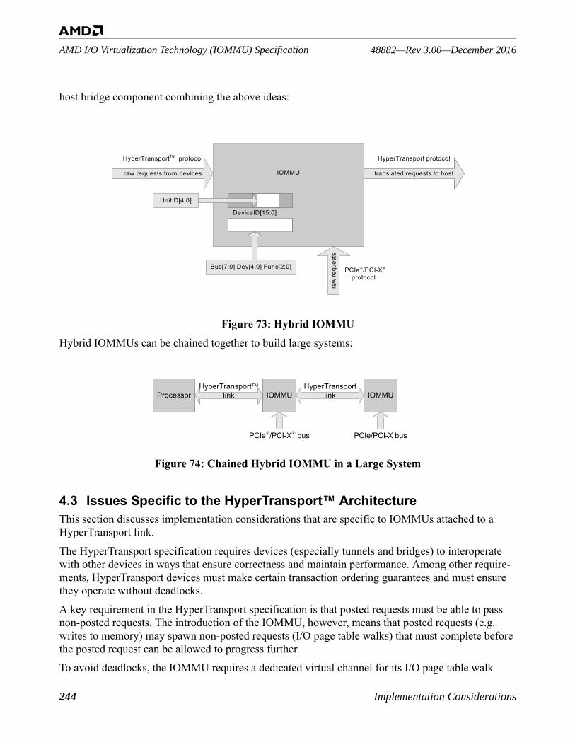
244 Implementation Considerations
48882—Rev 3.00—December 2016AMD I/O Virtualization Technology (IOMMU) Specification
host bridge component combining the above ideas:
Figure 73: Hybrid IOMMUHybrid IOMMUs can be chained together to build large systems:
Figure 74: Chained Hybrid IOMMU in a Large System
4.3 Issues Specific to the HyperTransport™ ArchitectureThis section discusses implementation considerations that are specific to IOMMUs attached to a HyperTransport link.The HyperTransport specification requires devices (especially tunnels and bridges) to interoperate with other devices in ways that ensure correctness and maintain performance. Among other require-ments, HyperTransport devices must make certain transaction ordering guarantees and must ensure they operate without deadlocks.A key requirement in the HyperTransport specification is that posted requests must be able to pass non-posted requests. The introduction of the IOMMU, however, means that posted requests (e.g. writes to memory) may spawn non-posted requests (I/O page table walks) that must complete before the posted request can be allowed to progress further.To avoid deadlocks, the IOMMU requires a dedicated virtual channel for its I/O page table walk
IOMMU
HyperTransportTM protocol
raw requests from devices
HyperTransport protocol
translated requests to host
UnitID[4:0]
raw
requ
ests
PCIe®/PCI-X® protocol
Bus[7:0] Dev[4:0] Func[2:0]
DeviceID[15:0]
IOMMU
PCIe®/PCI-X® bus
IOMMU
PCIe/PCI-X bus
ProcessorHyperTransport
linkHyperTransport™
link
Implementation Considerations 245
AMD I/O Virtualization Technology (IOMMU) Specification48882—Rev 3.00—December 2016
requests. This ensures that, the IOMMU’s page table walks on behalf of posted requests can com-plete, regardless of the completion status of other non-posted traffic in the fabric. The IOMMU also requires that the host bridge process its requests without spawning any requests to other devices. In other words, the IOMMU’s table structures must be located solely in system memory.The IOMMU can share its virtual channel with other traffic as long the other traffic is also guaranteed to make forward progress. In practice, this means that any other devices sharing the IOMMU’s page walk channel must also restrict their non-posted traffic solely to accessing system memory. To allow the IOMMU to support different AMD processors with different isochronous capabilities the IOMMU control registers contain bits that control the state of the PassPW bits, the coherent bit and the isochronous bit in the HyperTransport™ link read request issued by the IOMMU.
4.4 Chipset Specific Implementation IssuesChipsets that implement both an IOMMU and a legacy PCI or AGP bridge must provide source iden-tification to identify uniquely DMA traffic as originating from the PCI or AGP bus.To provide this identification, the IOMMU must use the requesterID of the PCI or AGP bridge to perform transla-tions for DMA transactions from the legacy bus. The Device legacy ID information must be reported via appropriate ACPI or Device Tree table entries. Details are in Section 5.2.2 [I/O Virtualization Definition Blocks].
4.5 Software and Platform Firmware Implementation IssuesBecause of the flexible architecture of the IOMMU, it is unlikely that any single system software implementation uses all the features, topologies, or options. The following constraints are strongly recommended:• An IOMMU should be a root-complex device (i.e., appear directly on the bus at the top of the PCI
tree hierarchy).• Some system software may prohibit an IOMMU from appearing under a PCI-to-PCI bridge. • To ensure the IOMMU is recognized and configured properly, the platform firmware should
perform the initial configuration of the IOMMU so that it is accessible to system software when control is handed off by the platform firmware.
• The platform firmware should describe the IOMMU in an ACPI table as defined in Chapter 5, "I/O Virtualization ACPI Table". The table must include all information necessary to identify, configure, and access the IOMMU. It is recommended that System software retrieves IOMMU hardware information from ACPI and Firmware tables, in descending order of priority from Type11h table, if not available to Type10h IVHD tables, finally evaluating IOMMU MMIO feature registers if no other property is available or accessible.
• System firmware must ensure the IOMMU configuration is preserved or restored across power-management state changes.
246 Implementation Considerations
48882—Rev 3.00—December 2016AMD I/O Virtualization Technology (IOMMU) Specification
I/O Virtualization ACPI Table 247
AMD I/O Virtualization Technology (IOMMU) Specification48882—Rev 3.00—December 2016
5 I/O Virtualization ACPI Table
The architecture defines an ACPI-compatible data structure called an I/O Virtualization Reporting Structure (IVRS) that is used to convey information related to I/O virtualization to system software. The IVRS describes the configuration and capabilities of the IOMMUs contained in the platform as well as information about the devices that each IOMMU virtualizes.The IVRS provides information about the following:• IOMMUs present in the platform including their capabilities and proper configuration• System I/O topology relevant to each IOMMU• Peripheral devices that cannot be otherwise enumerated• Memory regions used by SMI/SMM, platform firmware, and platform hardware. These are
generally exclusion ranges to be configured by system software.Software Implementation Note: Information conveyed in the IVRS overrides the corresponding information available through the IOMMU hardware registers. System software is required to honor the ACPI settings.
The IVRS is created in memory by the platform firmware. There are two formats for the IVRS, one that supports fixed DeviceID I/O devices only and a second format that supports both fixed DeviceID devices and ACPI Hardware ID (HID) devices. System software must be capable of handling both formats. The Revision field in the IVRS header identifies the format of a given IVRS. Note: This revision number does not correspond to a revision level of the IOMMU implementation.
Following the header, the IVRS contains one or more I/O Virtualization Definition Blocks (IVDBs).There are two types of IVDBs: 1. I/O Virtualization Hardware Definition (IVHD) block.
An IVHD provides specific information about each IOMMU in the platform and the devices attached downstream of the IOMMU.
2. I/O Virtualization Memory Definition (IVMD) block. An IVMD is used to describe any special memory constraints.
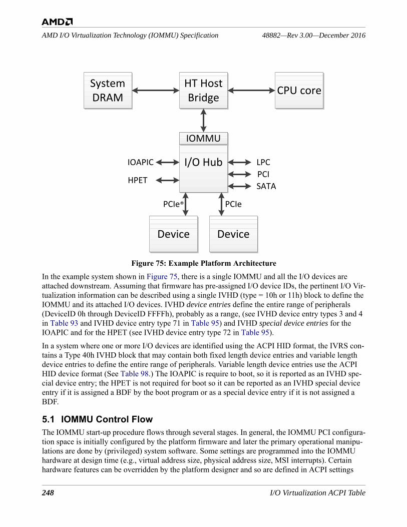
248 I/O Virtualization ACPI Table
48882—Rev 3.00—December 2016AMD I/O Virtualization Technology (IOMMU) Specification
Figure 75: Example Platform ArchitectureIn the example system shown in Figure 75, there is a single IOMMU and all the I/O devices are attached downstream. Assuming that firmware has pre-assigned I/O device IDs, the pertinent I/O Vir-tualization information can be described using a single IVHD (type = 10h or 11h) block to define the IOMMU and its attached I/O devices. IVHD device entries define the entire range of peripherals (DeviceID 0h through DeviceID FFFFh), probably as a range, (see IVHD device entry types 3 and 4 in Table 93 and IVHD device entry type 71 in Table 95) and IVHD special device entries for the IOAPIC and for the HPET (see IVHD device entry type 72 in Table 95).In a system where one or more I/O devices are identified using the ACPI HID format, the IVRS con-tains a Type 40h IVHD block that may contain both fixed length device entries and variable length device entries to define the entire range of peripherals. Variable length device entries use the ACPI HID device format (See Table 98.) The IOAPIC is require to boot, so it is reported as an IVHD spe-cial device entry; the HPET is not required for boot so it can be reported as an IVHD special device entry if it is assigned a BDF by the boot program or as a special device entry if it is not assigned a BDF.
5.1 IOMMU Control FlowThe IOMMU start-up procedure flows through several stages. In general, the IOMMU PCI configura-tion space is initially configured by the platform firmware and later the primary operational manipu-lations are done by (privileged) system software. Some settings are programmed into the IOMMU hardware at design time (e.g., virtual address size, physical address size, MSI interrupts). Certain hardware features can be overridden by the platform designer and so are defined in ACPI settings
HT Host Bridge
System DRAM CPU core
I/O Hub
IOMMU
Device Device
LPCPCISATA
IOAPIC
HPET
PCIePCIe®
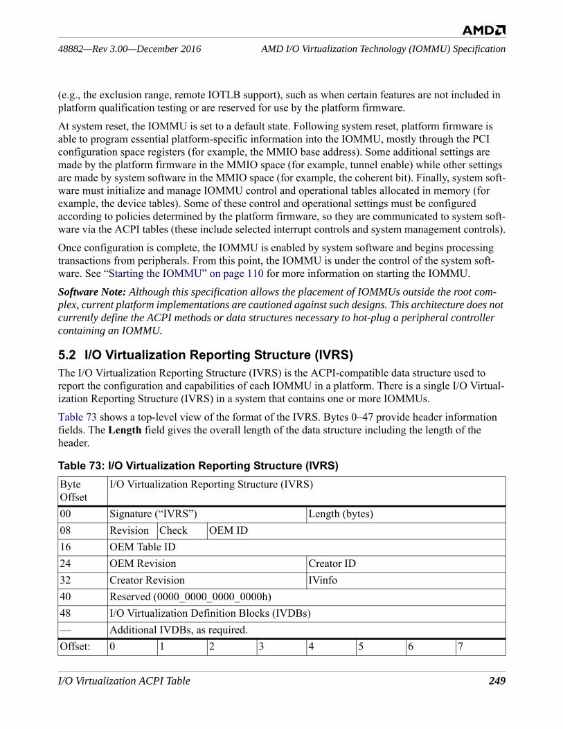
I/O Virtualization ACPI Table 249
AMD I/O Virtualization Technology (IOMMU) Specification48882—Rev 3.00—December 2016
(e.g., the exclusion range, remote IOTLB support), such as when certain features are not included in platform qualification testing or are reserved for use by the platform firmware. At system reset, the IOMMU is set to a default state. Following system reset, platform firmware is able to program essential platform-specific information into the IOMMU, mostly through the PCI configuration space registers (for example, the MMIO base address). Some additional settings are made by the platform firmware in the MMIO space (for example, tunnel enable) while other settings are made by system software in the MMIO space (for example, the coherent bit). Finally, system soft-ware must initialize and manage IOMMU control and operational tables allocated in memory (for example, the device tables). Some of these control and operational settings must be configured according to policies determined by the platform firmware, so they are communicated to system soft-ware via the ACPI tables (these include selected interrupt controls and system management controls).Once configuration is complete, the IOMMU is enabled by system software and begins processing transactions from peripherals. From this point, the IOMMU is under the control of the system soft-ware. See “Starting the IOMMU” on page 110 for more information on starting the IOMMU.Software Note: Although this specification allows the placement of IOMMUs outside the root com-plex, current platform implementations are cautioned against such designs. This architecture does not currently define the ACPI methods or data structures necessary to hot-plug a peripheral controller containing an IOMMU.
5.2 I/O Virtualization Reporting Structure (IVRS)The I/O Virtualization Reporting Structure (IVRS) is the ACPI-compatible data structure used to report the configuration and capabilities of each IOMMU in a platform. There is a single I/O Virtual-ization Reporting Structure (IVRS) in a system that contains one or more IOMMUs.Table 73 shows a top-level view of the format of the IVRS. Bytes 0–47 provide header information fields. The Length field gives the overall length of the data structure including the length of the header.
Table 73: I/O Virtualization Reporting Structure (IVRS)ByteOffset
I/O Virtualization Reporting Structure (IVRS)
00 Signature (“IVRS”) Length (bytes)08 Revision Check OEM ID16 OEM Table ID24 OEM Revision Creator ID32 Creator Revision IVinfo40 Reserved (0000_0000_0000_0000h)48 I/O Virtualization Definition Blocks (IVDBs)— Additional IVDBs, as required.Offset: 0 1 2 3 4 5 6 7
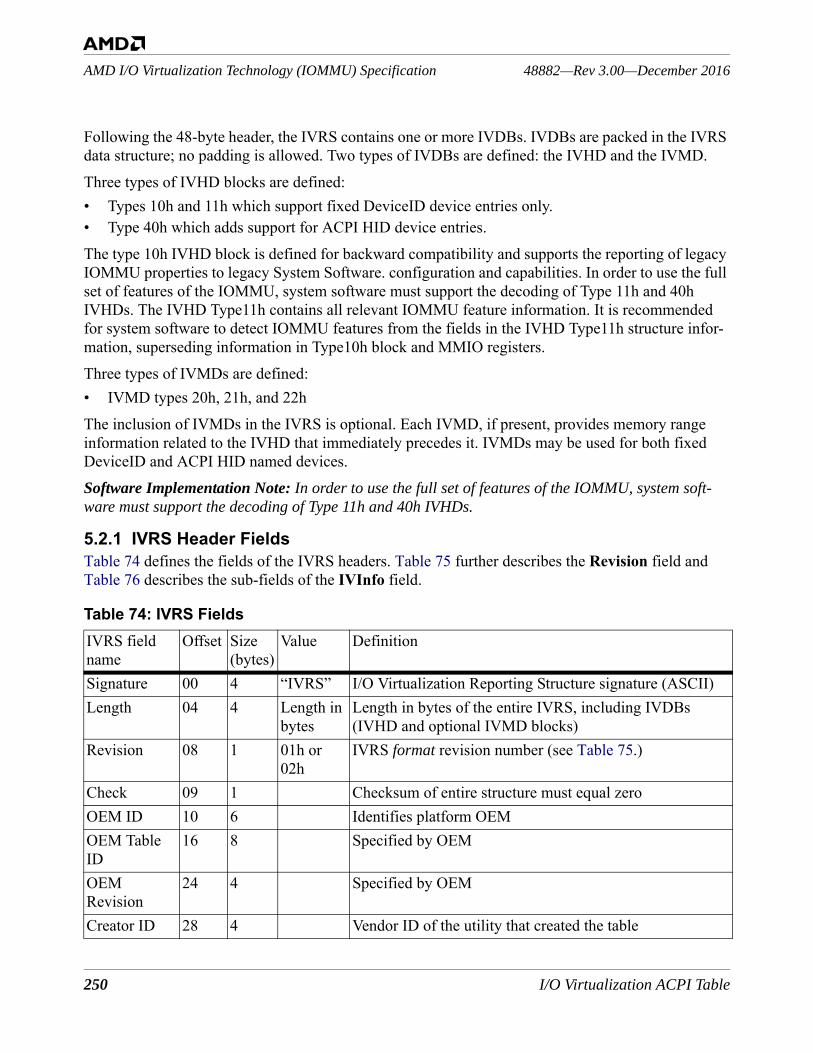
250 I/O Virtualization ACPI Table
48882—Rev 3.00—December 2016AMD I/O Virtualization Technology (IOMMU) Specification
Following the 48-byte header, the IVRS contains one or more IVDBs. IVDBs are packed in the IVRS data structure; no padding is allowed. Two types of IVDBs are defined: the IVHD and the IVMD.Three types of IVHD blocks are defined: • Types 10h and 11h which support fixed DeviceID device entries only.• Type 40h which adds support for ACPI HID device entries.The type 10h IVHD block is defined for backward compatibility and supports the reporting of legacy IOMMU properties to legacy System Software. configuration and capabilities. In order to use the full set of features of the IOMMU, system software must support the decoding of Type 11h and 40h IVHDs. The IVHD Type11h contains all relevant IOMMU feature information. It is recommended for system software to detect IOMMU features from the fields in the IVHD Type11h structure infor-mation, superseding information in Type10h block and MMIO registers. Three types of IVMDs are defined: • IVMD types 20h, 21h, and 22hThe inclusion of IVMDs in the IVRS is optional. Each IVMD, if present, provides memory range information related to the IVHD that immediately precedes it. IVMDs may be used for both fixed DeviceID and ACPI HID named devices.Software Implementation Note: In order to use the full set of features of the IOMMU, system soft-ware must support the decoding of Type 11h and 40h IVHDs.
5.2.1 IVRS Header FieldsTable 74 defines the fields of the IVRS headers. Table 75 further describes the Revision field and Table 76 describes the sub-fields of the IVInfo field.
Table 74: IVRS FieldsIVRS field name
Offset Size (bytes)
Value Definition
Signature 00 4 “IVRS” I/O Virtualization Reporting Structure signature (ASCII)Length 04 4 Length in
bytesLength in bytes of the entire IVRS, including IVDBs (IVHD and optional IVMD blocks)
Revision 08 1 01h or 02h
IVRS format revision number (see Table 75.)
Check 09 1 Checksum of entire structure must equal zeroOEM ID 10 6 Identifies platform OEMOEM Table ID
16 8 Specified by OEM
OEMRevision
24 4 Specified by OEM
Creator ID 28 4 Vendor ID of the utility that created the table
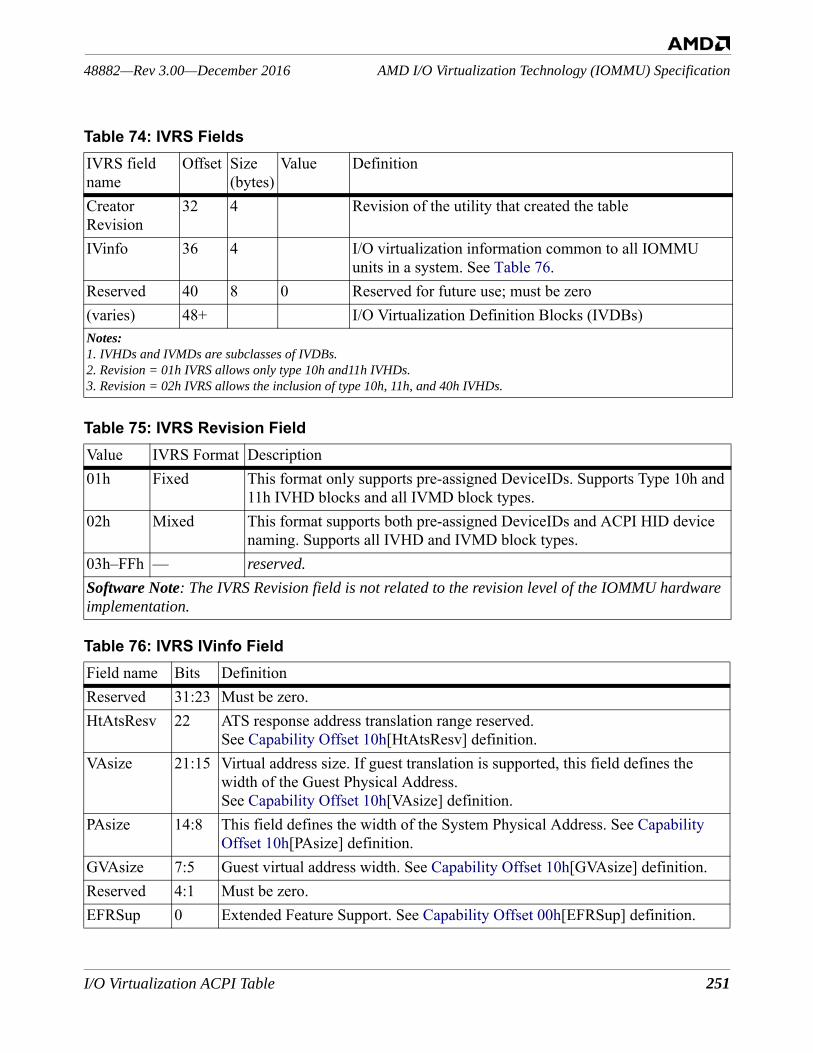
I/O Virtualization ACPI Table 251
AMD I/O Virtualization Technology (IOMMU) Specification48882—Rev 3.00—December 2016
Creator Revision
32 4 Revision of the utility that created the table
IVinfo 36 4 I/O virtualization information common to all IOMMU units in a system. See Table 76.
Reserved 40 8 0 Reserved for future use; must be zero(varies) 48+ I/O Virtualization Definition Blocks (IVDBs)Notes:1. IVHDs and IVMDs are subclasses of IVDBs.2. Revision = 01h IVRS allows only type 10h and11h IVHDs.3. Revision = 02h IVRS allows the inclusion of type 10h, 11h, and 40h IVHDs.
Table 75: IVRS Revision FieldValue IVRS Format Description01h Fixed This format only supports pre-assigned DeviceIDs. Supports Type 10h and
11h IVHD blocks and all IVMD block types.02h Mixed This format supports both pre-assigned DeviceIDs and ACPI HID device
naming. Supports all IVHD and IVMD block types.03h–FFh — reserved.Software Note: The IVRS Revision field is not related to the revision level of the IOMMU hardware implementation.
Table 76: IVRS IVinfo FieldField name Bits DefinitionReserved 31:23 Must be zero.HtAtsResv 22 ATS response address translation range reserved.
See Capability Offset 10h[HtAtsResv] definition.VAsize 21:15 Virtual address size. If guest translation is supported, this field defines the
width of the Guest Physical Address.See Capability Offset 10h[VAsize] definition.
PAsize 14:8 This field defines the width of the System Physical Address. See Capability Offset 10h[PAsize] definition.
GVAsize 7:5 Guest virtual address width. See Capability Offset 10h[GVAsize] definition.Reserved 4:1 Must be zero.EFRSup 0 Extended Feature Support. See Capability Offset 00h[EFRSup] definition.
Table 74: IVRS FieldsIVRS field name
Offset Size (bytes)
Value Definition
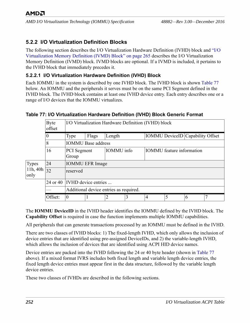
252 I/O Virtualization ACPI Table
48882—Rev 3.00—December 2016AMD I/O Virtualization Technology (IOMMU) Specification
5.2.2 I/O Virtualization Definition BlocksThe following section describes the I/O Virtualization Hardware Definition (IVHD) block and “I/O Virtualization Memory Definition (IVMD) Block” on page 265 describes the I/O Virtualization Memory Definition (IVMD) block. IVMD blocks are optional. If a IVMD is included, it pertains to the IVHD block that immediately precedes it.5.2.2.1 I/O Virtualization Hardware Definition (IVHD) BlockEach IOMMU in the system is described by one IVHD block. The IVHD block is shown Table 77 below. An IOMMU and the peripherals it serves must be on the same PCI Segment defined in the IVHD block. The IVHD block contains at least one IVHD device entry. Each entry describes one or a range of I/O devices that the IOMMU virtualizes.
The IOMMU DeviceID in the IVHD header identifies the IOMMU defined by the IVHD block. The Capability Offset is required in case the function implements multiple IOMMU capabilities.All peripherals that can generate transactions processed by an IOMMU must be defined in the IVHD.There are two classes of IVHD blocks: 1) The fixed-length IVHD, which only allows the inclusion of device entries that are identified using pre-assigned DeviceIDs, and 2) the variable-length IVHD, which allows the inclusion of devices that are identified using ACPI HID device names.Device entries are packed into the IVHD following the 24 or 40 byte header (shown in Table 77 above). If a mixed format IVRS includes both fixed length and variable length device entries, the fixed length device entries must appear first in the data structure, followed by the variable length device entries.These two classes of IVHDs are described in the following sections.
Table 77: I/O Virtualization Hardware Definition (IVHD) Block Generic FormatByteoffset
I/O Virtualization Hardware Definition (IVHD) block
0 Type Flags Length IOMMU DeviceID Capability Offset8 IOMMU Base address16 PCI Segment
GroupIOMMU info IOMMU feature information
Types 11h, 40h only
24 IOMMU EFR Image32 reserved
24 or 40 IVHD device entries ...— Additional device entries as required.Offset: 0 1 2 3 4 5 6 7
I/O Virtualization ACPI Table 253
AMD I/O Virtualization Technology (IOMMU) Specification48882—Rev 3.00—December 2016
Fixed-Length IVHD BlocksThe IVHD device entries, which follow the 24 or 40 byte header, describe the I/O topology (start and end of a range, or single entries) of I/O devices and slots served by an IOMMU. All possible Device IDs must be defined, whether the DeviceID is actually populated or not. Device entries are used to report ranges when hot-plug and SR-IOV devices are possible. Each DeviceID is described by one IVHD device entry which may be a select or select-alias record or is part of a range or an alias range. If a given DeviceID exists but can generate neither DMA nor interrupts (ever), it need not be listed in the IVHD block. A DeviceID used as an alias must be included in the device list (either “select” or “range”). The simplest IVRS contains one DeviceID range for each IOMMU; a system with one IOMMU may report as little as a single range covering all DeviceIDs (0000h–FFFFh).Implementation Note: all DeviceID values served by an IOMMU must be reported in an IVHD block including DeviceIDs not yet populated (including, but not limited to, virtual functions and empty hot-plug slots).
There must be at least one IVHD device entry to describe at least one I/O device or slot governed by the IOMMU; an IOMMU may govern multiple ranges and singletons of I/O devices. A IVHD device entry can provide information about a single device, a sub-range of devices, or all the devices virtual-ized by that IOMMU. When a IVHD device entry defines the start of a range, a second device entry, immediately following the first, defines the end of the range. The range definition is inclusive of the first and last device specified. IVHD device entries specify the settings for specific IOMMU DTE fields for that device or range of devices in the IOMMU Device Table.See “IVHD Device Entries” on page 261 for more information on device entries.For peripherals that use source identification other than their own DeviceID, alias entries must be used. An IOMMU and the peripherals it serves must be on the same PCI Segment Group defined in the IVHD block. At this time, only PCI Segment Group 0 is supported. The IVHD length field speci-fies the number of bytes in the IVHD block, starting from the Type field.There are two types of fixed-length IVHDs defined: Type 10h and Type 11h. Table 78, Table 79, Table 80, Table 81, Table 82, and Figure 76 define the Type 10h IVHD and Table 83, Table 84, Table 85, and Table 86 define the Type 11h IVHD.
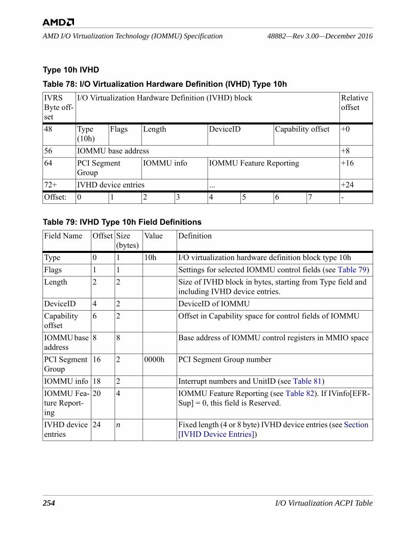
254 I/O Virtualization ACPI Table
48882—Rev 3.00—December 2016AMD I/O Virtualization Technology (IOMMU) Specification
Type 10h IVHDTable 78: I/O Virtualization Hardware Definition (IVHD) Type 10hIVRS Byte off-set
I/O Virtualization Hardware Definition (IVHD) block Relative offset
48 Type(10h)
Flags Length DeviceID Capability offset +0
56 IOMMU base address +864 PCI Segment
GroupIOMMU info IOMMU Feature Reporting +16
72+ IVHD device entries ... +24Offset: 0 1 2 3 4 5 6 7 -
Table 79: IVHD Type 10h Field DefinitionsField Name Offset Size
(bytes)Value Definition
Type 0 1 10h I/O virtualization hardware definition block type 10hFlags 1 1 Settings for selected IOMMU control fields (see Table 79)Length 2 2 Size of IVHD block in bytes, starting from Type field and
including IVHD device entries.DeviceID 4 2 DeviceID of IOMMUCapability offset
6 2 Offset in Capability space for control fields of IOMMU
IOMMU base address
8 8 Base address of IOMMU control registers in MMIO space
PCI Segment Group
16 2 0000h PCI Segment Group number
IOMMU info 18 2 Interrupt numbers and UnitID (see Table 81)IOMMU Fea-ture Report-ing
20 4 IOMMU Feature Reporting (see Table 82). If IVinfo[EFR-Sup] = 0, this field is Reserved.
IVHD device entries
24 n Fixed length (4 or 8 byte) IVHD device entries (see Section [IVHD Device Entries])
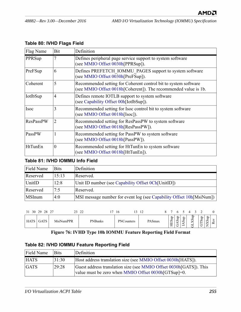
I/O Virtualization ACPI Table 255
AMD I/O Virtualization Technology (IOMMU) Specification48882—Rev 3.00—December 2016
Figure 76: IVHD Type 10h IOMMU Feature Reporting Field Format
Table 80: IVHD Flags FieldFlag Name Bit DefinitionPPRSup 7 Defines peripheral page service support to system software
(see MMIO Offset 0030h[PPRSup]).PreFSup 6 Defines PREFETCH_IOMMU_PAGES support to system software
(see MMIO Offset 0030h[PreFSup]).Coherent 5 Recommended setting for Coherent control bit to system software
(see MMIO Offset 0018h[Coherent]). The recommended value is 1b.IotlbSup 4 Defines remote IOTLB support to system software
(see Capability Offset 00h[IotlbSup]).Isoc 3 Recommended setting for Isoc control bit to system software
(see MMIO Offset 0018h[Isoc]).ResPassPW 2 Recommended setting for ResPassPW to system software
(see MMIO Offset 0018h[ResPassPW]).PassPW 1 Recommended setting for PassPW to system software
(see MMIO Offset 0018h[PassPW]).HtTunEn 0 Recommended setting for HtTunEn to system software
(see MMIO Offset 0018h[HtTunEn]).
Table 81: IVHD IOMMU Info FieldField Name Bits DefinitionReserved 15:13 Reserved.UnitID 12:8 Unit ID number (see Capability Offset 0Ch[UnitID])Reserved 7:5 Reserved.MSInum 4:0 MSI message number for event log (see Capability Offset 10h[MsiNum])
31 30 29 28 27 23 22 17 16 13 12 8 7 6 5 4 3 2 0
HATS GATS MsiNumPPR PNBanks PNCounters PASmax
HES
up
GA
Sup
IASu
p
GLX
Sup
GTS
up
NX
Sup
Rsv
Table 82: IVHD IOMMU Feature Reporting FieldField Name Bits DefinitionHATS 31:30 Host address translation size (see MMIO Offset 0030h[HATS]).GATS 29:28 Guest address translation size (see MMIO Offset 0030h[GATS]). This
value must be zero when MMIO Offset 0030h[GTSup]=0.
256 I/O Virtualization ACPI Table
48882—Rev 3.00—December 2016AMD I/O Virtualization Technology (IOMMU) Specification
Software Note: Using the information contained in a Type 10h IVHD an indication of support for the performance counter feature can be derived from the IOMMU Feature Reporting Fields PNBanks and PNCounters. When PNBanks and PNCounters both equal 0, then the performance counter fea-ture is not supported. (see MMIO Offset 0030h[PCSup]). The Type 11h IVHD (see the next section) supplies a direct indication of support for the performance counter feature by providing an image of the IOMMU Extended Feature Register [MMIO Offset 0030h] hardware register.
MsiNumPPR 27:23 MsiNumPPR for peripheral page requests (see Capability Offset 10h[MsiNumPPR]); must be 0_0000b when MMIO Offset 0030h[PPR-Sup] = 0.
PNBanks 22:17 Number of performance counter banks (see MMIO Offset 4000h[NCoun-terBanks]).
PNCounters 16:13 Number of performance counters per counter bank (see MMIO Offset 4000h[NCounter]).
PASmax 12:8 Parameter that indicates the maximum PASID value supported by the IOMMU (see MMIO Offset 0030h[PASmax]). Must be ignored if MMIO Offset 0030h[PPRSup] = 0.
HESup 7 Hardware Error Registers supported (see Section 2.5.12.2 [I/O Hardware Event Reporting Registers]).
GASup 6 Guest virtual APIC supported (see MMIO Offset 0030h[GASup]).IASup 5 INVALIDATE_IOMMU_ALL supported (see MMIO Offset
0030h[IASup]).GLXSup 4:3 Number of guest CR3 tables supported (see MMIO Offset 0030h[GLX-
Sup]). GTSup 2 Guest translation supported (see MMIO Offset 0030h[GTSup]).NXSup 1 NX supported for I/O (see MMIO Offset 0030h[NXSup]).— 0 Reserved.
Table 82: IVHD IOMMU Feature Reporting FieldField Name Bits Definition
I/O Virtualization ACPI Table 257
AMD I/O Virtualization Technology (IOMMU) Specification48882—Rev 3.00—December 2016
Type 11h IVHDIf IVinfo[EFRSup] = 0, IVHD Type 11h is Reserved.
Table 83: I/O Virtualization Hardware Definition (IVHD) Type 11hIVRS Byte off-set
I/O Virtualization Hardware Definition (IVHD) block Relative offset
48 Type(11h)
Flags Length DeviceID Capability offset +0
56 IOMMU base address +864 PCI Segment
GroupIOMMU info IOMMU Attributes +16
72 EFR Register Image +2480 Reserved +3288+ IVHD device entries +40Offset: 0 1 2 3 4 5 6 7 -
Table 84: IVHD Type 11h Field DefinitionsField Name Offset Size
(bytes)Value Definition
Type 0 1 11h I/O virtualization hardware definition block type 11hFlags 1 1 Recommended settings for selected IOMMU control fields
See Table 85Length 2 2 (bytes) Size of IVHD block in bytes, starting from Type field and
including IVHD device entries.DeviceID 4 2 DeviceID of IOMMUCapability offset
6 2 Offset in Capability space for control fields of IOMMU
IOMMU base address
8 8 Base address of IOMMU control registers in MMIO space
PCI Segment Group
16 2 0000h PCI Segment Group number
IOMMU info 18 2 Interrupt numbers and UnitID (Table 81)IOMMU Attributes
20 4 IOMMU information not reported in the MMIO Offset 30h Extended Feature Register (Table 86)
EFR Register Image
24 8 Exact copy of the IOMMU Extended Feature Register [MMIO Offset 0030h]
258 I/O Virtualization ACPI Table
48882—Rev 3.00—December 2016AMD I/O Virtualization Technology (IOMMU) Specification
reserved 32 8 Reserved for future IOMMU feature info.IVHD device entries
40 n Fixed length (4 or 8 byte) IVHD device entries. See Sec-tion [IVHD Device Entries]
Table 85: IVHD Flags FieldFlag Name Bit Definition— 7 Reserved— 6 ReservedCoherent 5 Recommended setting for Coherent control bit to system software
(see MMIO Offset 0018h[Coherent]). The recommended value is 1b.IotlbSup 4 Defines remote IOTLB support to system software
(see Capability Offset 00h[IotlbSup]).Isoc 3 Recommended setting for Isoc control bit to system software
(see MMIO Offset 0018h[Isoc]).ResPassPW 2 Recommended setting for ResPassPW to system software
(see MMIO Offset 0018h[ResPassPW]).PassPW 1 Recommended setting for PassPW to system software
(see MMIO Offset 0018h[PassPW]).HtTunEn 0 Recommended setting for HtTunEn to system software
(see MMIO Offset 0018h[HtTunEn]).
Table 86: IVHD Type 11h IOMMU AttributesField Name Bits Definition— 31:28 Reserved.MsiNumPPR 27:23 MsiNumPPR for peripheral page requests (see Capability Offset
10h[MsiNumPPR])PNBanks 22:17 Number of performance counter banks (see MMIO Offset 4000h[NCoun-
terBanks]).PNCounters 16:13 Number of performance counters per counter bank (see MMIO Offset
4000h[NCounter]).— 12:0 Reserved.
Table 84: IVHD Type 11h Field Definitions (Continued)Field Name Offset Size
(bytes)Value Definition
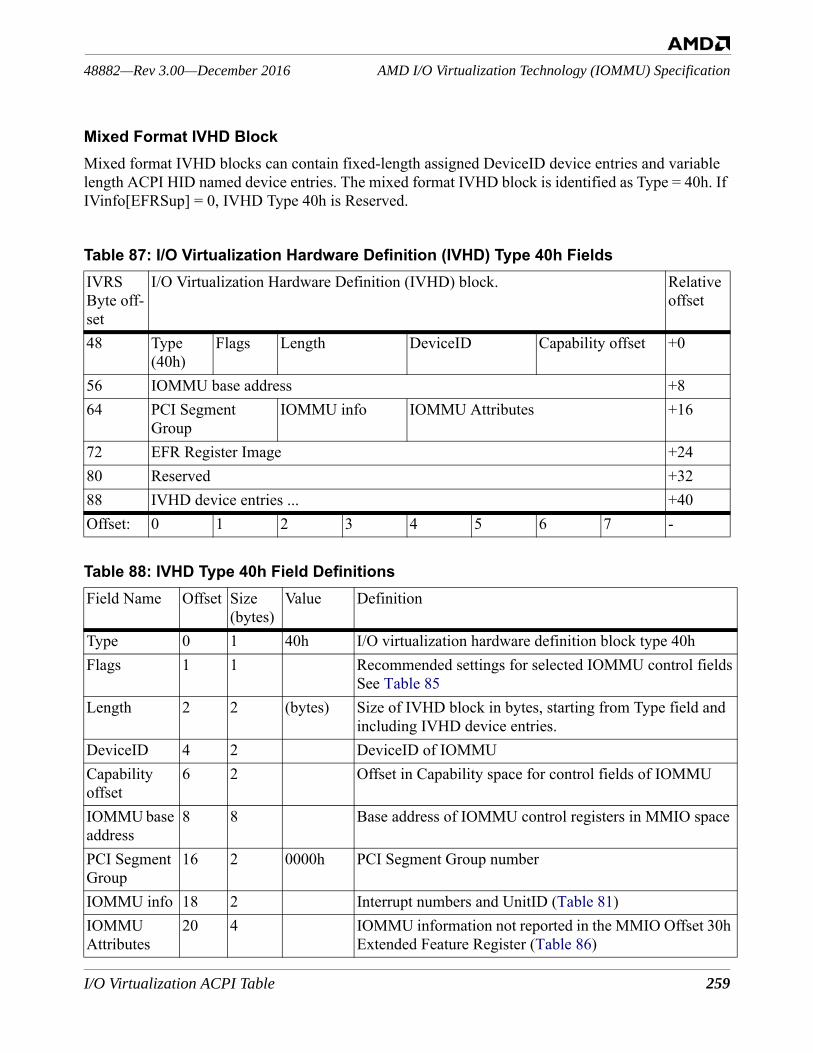
I/O Virtualization ACPI Table 259
AMD I/O Virtualization Technology (IOMMU) Specification48882—Rev 3.00—December 2016
Mixed Format IVHD BlockMixed format IVHD blocks can contain fixed-length assigned DeviceID device entries and variable length ACPI HID named device entries. The mixed format IVHD block is identified as Type = 40h. If IVinfo[EFRSup] = 0, IVHD Type 40h is Reserved.
Table 87: I/O Virtualization Hardware Definition (IVHD) Type 40h FieldsIVRS Byte off-set
I/O Virtualization Hardware Definition (IVHD) block. Relative offset
48 Type(40h)
Flags Length DeviceID Capability offset +0
56 IOMMU base address +864 PCI Segment
GroupIOMMU info IOMMU Attributes +16
72 EFR Register Image +2480 Reserved +3288 IVHD device entries ... +40Offset: 0 1 2 3 4 5 6 7 -
Table 88: IVHD Type 40h Field DefinitionsField Name Offset Size
(bytes)Value Definition
Type 0 1 40h I/O virtualization hardware definition block type 40hFlags 1 1 Recommended settings for selected IOMMU control fields
See Table 85Length 2 2 (bytes) Size of IVHD block in bytes, starting from Type field and
including IVHD device entries.DeviceID 4 2 DeviceID of IOMMUCapability offset
6 2 Offset in Capability space for control fields of IOMMU
IOMMU base address
8 8 Base address of IOMMU control registers in MMIO space
PCI Segment Group
16 2 0000h PCI Segment Group number
IOMMU info 18 2 Interrupt numbers and UnitID (Table 81)IOMMU Attributes
20 4 IOMMU information not reported in the MMIO Offset 30h Extended Feature Register (Table 86)
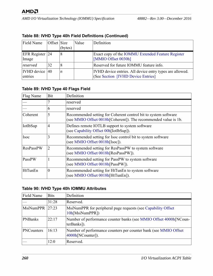
260 I/O Virtualization ACPI Table
48882—Rev 3.00—December 2016AMD I/O Virtualization Technology (IOMMU) Specification
EFR Register Image
24 8 Exact copy of the IOMMU Extended Feature Register [MMIO Offset 0030h]
reserved 32 8 Reserved for future IOMMU feature info.IVHD device entries
40 n IVHD device entries. All device entry types are allowed. (See Section [IVHD Device Entries]
Table 89: IVHD Type 40 Flags FieldFlag Name Bit Definition— 7 reserved— 6 reservedCoherent 5 Recommended setting for Coherent control bit to system software
(see MMIO Offset 0018h[Coherent]). The recommended value is 1b.IotlbSup 4 Defines remote IOTLB support to system software
(see Capability Offset 00h[IotlbSup]).Isoc 3 Recommended setting for Isoc control bit to system software
(see MMIO Offset 0018h[Isoc]).ResPassPW 2 Recommended setting for ResPassPW to system software
(see MMIO Offset 0018h[ResPassPW]).PassPW 1 Recommended setting for PassPW to system software
(see MMIO Offset 0018h[PassPW]).HtTunEn 0 Recommended setting for HtTunEn to system software
(see MMIO Offset 0018h[HtTunEn]).
Table 90: IVHD Type 40h IOMMU AttributesField Name Bits Definition— 31:28 Reserved.MsiNumPPR 27:23 MsiNumPPR for peripheral page requests (see Capability Offset
10h[MsiNumPPR])PNBanks 22:17 Number of performance counter banks (see MMIO Offset 4000h[NCoun-
terBanks]).PNCounters 16:13 Number of performance counters per counter bank (see MMIO Offset
4000h[NCounter]).— 12:0 Reserved.
Table 88: IVHD Type 40h Field Definitions (Continued)Field Name Offset Size
(bytes)Value Definition
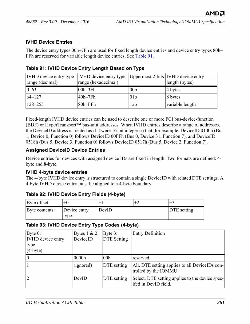
I/O Virtualization ACPI Table 261
AMD I/O Virtualization Technology (IOMMU) Specification48882—Rev 3.00—December 2016
IVHD Device EntriesThe device entry types 00h–7Fh are used for fixed length device entries and device entry types 80h–FFh are reserved for variable length device entries. See Table 91.
Fixed-length IVHD device entries can be used to describe one or more PCI bus-device-function (BDF) or HyperTransport™ bus-unit addresses. When IVHD entries describe a range of addresses, the DeviceID address is treated as if it were 16-bit integer so that, for example, DeviceID 0100h (Bus 1, Device 0, Function 0) follows DeviceID 00FFh (Bus 0, Device 31, Function 7), and DeviceID 0518h (Bus 5, Device 3, Function 0) follows DeviceID 0517h (Bus 5, Device 2, Function 7).Assigned DeviceID Device EntriesDevice entries for devices with assigned device IDs are fixed in length. Two formats are defined: 4-byte and 8-byte.IVHD 4-byte device entriesThe 4-byte IVHD device entry is structured to contain a single DeviceID with related DTE settings. A 4-byte IVHD device entry must be aligned to a 4-byte boundary.
Table 91: IVHD Device Entry Length Based on TypeIVHD device entry type range (decimal)
IVHD device entry type range (hexadecimal)
Uppermost 2-bits IVHD device entry length (bytes)
0–63 00h–3Fh 00b 4 bytes64–127 40h–7Fh 01b 8 bytes128–255 80h–FFh 1xb variable length
Table 92: IVHD Device Entry Fields (4-byte)Byte offset: +0 +1 +2 +3Byte contents: Device entry
typeDevID DTE setting
Table 93: IVHD Device Entry Type Codes (4-byte)Byte 0: IVHD device entry type (4-byte)
Bytes 1 & 2:DeviceID
Byte 3:DTE Setting
Entry Definition
0 0000h 00h reserved.1 (ignored) DTE setting All. DTE setting applies to all DeviceIDs con-
trolled by the IOMMU.2 DevID DTE setting Select. DTE setting applies to the device spec-
ifed in DevID field.
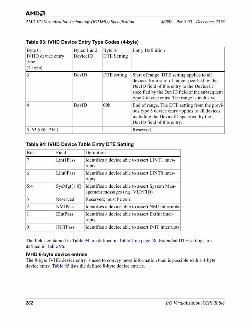
262 I/O Virtualization ACPI Table
48882—Rev 3.00—December 2016AMD I/O Virtualization Technology (IOMMU) Specification
The fields contained in Table 94 are defined in Table 7 on page 58. Extended DTE settings are defined in Table 96.IVHD 8-byte device entriesThe 8-byte IVHD device entry is used to convey more information than is possible with a 4-byte device entry. Table 95 lists the defined 8-byte device entries.
3 DevID DTE setting Start of range. DTE setting applies to all devices from start of range specified by the DevID field of this entry to the DeviceID specified by the DevID field of the subsequent type 4 device entry. The range is inclusive.
4 DevID 00h End of range. The DTE setting from the previ-ous type 3 device entry applies to all devices including the DeviceID specified by the DevID field of this entry.
5–63 (05h–3Fh) — — Reserved.
Table 94: IVHD Device Table Entry DTE SettingBits Field Definition7 Lint1Pass Identifies a device able to assert LINT1 inter-
rupts6 Lint0Pass Identifies a device able to assert LINT0 inter-
rupts5:4 SysMgt[1:0] Identifies a device able to assert System Man-
agement messages (e.g. VID/FID)3 Reserved Reserved; must be zero.2 NMIPass Identifies a device able to assert NMI interrupts1 EIntPass Identifies a device able to assert ExtInt inter-
rupts0 INITPass Identifies a device able to assert INIT interrupts
Table 93: IVHD Device Entry Type Codes (4-byte)Byte 0: IVHD device entry type (4-byte)
Bytes 1 & 2:DeviceID
Byte 3:DTE Setting
Entry Definition
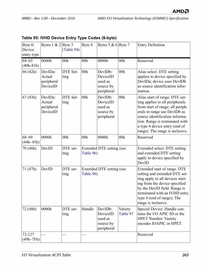
I/O Virtualization ACPI Table 263
AMD I/O Virtualization Technology (IOMMU) Specification48882—Rev 3.00—December 2016
Table 95: IVHD Device Entry Type Codes (8-byte)Byte 0: Device entry type
Bytes 1 & 2 Byte 3(Table 94)
Byte 4 Bytes 5 & 6 Byte 7 Entry Definition
64–65(40h-41h)
0000h 00h 00h 0000h 00h Reserved.
66 (42h) DevIDa: Actual peripheral DeviceID
DTE Set-ting
00h DevIDb: DeviceID used as source by peripheral
00h Alias select. DTE setting applies to device specified by DevIDa; device uses DevIDb as source identification infor-mation.
67 (43h) DevIDa: Actual peripheral DeviceID
DTE Set-ting
00h DevIDb: DeviceID used as source by peripheral
00h Alias start of range. DTE set-ting applies to all peripherals from start of range; all periph-erals in range use DevIDb as source identification informa-tion. Range is terminated with a type 4 device entry (end of range). The range is inclusive.
68–69(44h–45h)
0000h 00h 00h 0000h 00h Reserved
70 (46h) DevID DTE set-ting
Extended DTE setting (see Table 96)
Extended select. DTE setting and extended DTE setting apply to device specified by DevID
71 (47h) DevID DTE set-ting
Extended DTE setting (see Table 96)
Extended start of range. DTE setting and extended DTE set-ting apply to all devices start-ing from the device specified by the DevID field. Range is terminated with an IVHD entry type 4 (end of range); The range is inclusive.
72 (48h) 0000h DTE set-ting
Handle DevIDb: DeviceID used as source by peripheral
VarietyTable 97
Special Device. Handle con-tains the I/O APIC ID or the HPET Number. Variety encodes IOAPIC or HPET.
73-127(49h–7Fh)
— — — Reserved
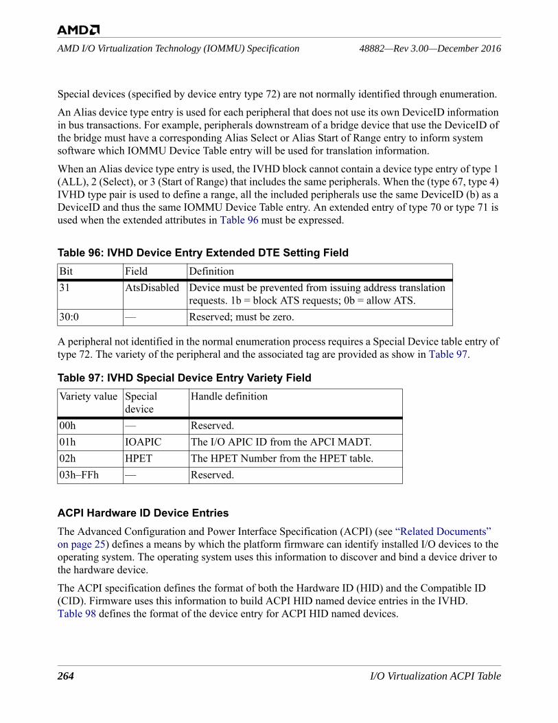
264 I/O Virtualization ACPI Table
48882—Rev 3.00—December 2016AMD I/O Virtualization Technology (IOMMU) Specification
Special devices (specified by device entry type 72) are not normally identified through enumeration. An Alias device type entry is used for each peripheral that does not use its own DeviceID information in bus transactions. For example, peripherals downstream of a bridge device that use the DeviceID of the bridge must have a corresponding Alias Select or Alias Start of Range entry to inform system software which IOMMU Device Table entry will be used for translation information. When an Alias device type entry is used, the IVHD block cannot contain a device type entry of type 1 (ALL), 2 (Select), or 3 (Start of Range) that includes the same peripherals. When the (type 67, type 4) IVHD type pair is used to define a range, all the included peripherals use the same DeviceID (b) as a DeviceID and thus the same IOMMU Device Table entry. An extended entry of type 70 or type 71 is used when the extended attributes in Table 96 must be expressed.
A peripheral not identified in the normal enumeration process requires a Special Device table entry of type 72. The variety of the peripheral and the associated tag are provided as show in Table 97.
ACPI Hardware ID Device EntriesThe Advanced Configuration and Power Interface Specification (ACPI) (see “Related Documents” on page 25) defines a means by which the platform firmware can identify installed I/O devices to the operating system. The operating system uses this information to discover and bind a device driver to the hardware device.The ACPI specification defines the format of both the Hardware ID (HID) and the Compatible ID (CID). Firmware uses this information to build ACPI HID named device entries in the IVHD. Table 98 defines the format of the device entry for ACPI HID named devices.
Table 96: IVHD Device Entry Extended DTE Setting FieldBit Field Definition31 AtsDisabled Device must be prevented from issuing address translation
requests. 1b = block ATS requests; 0b = allow ATS.30:0 — Reserved; must be zero.
Table 97: IVHD Special Device Entry Variety FieldVariety value Special
deviceHandle definition
00h — Reserved.01h IOAPIC The I/O APIC ID from the APCI MADT.02h HPET The HPET Number from the HPET table.03h–FFh — Reserved.
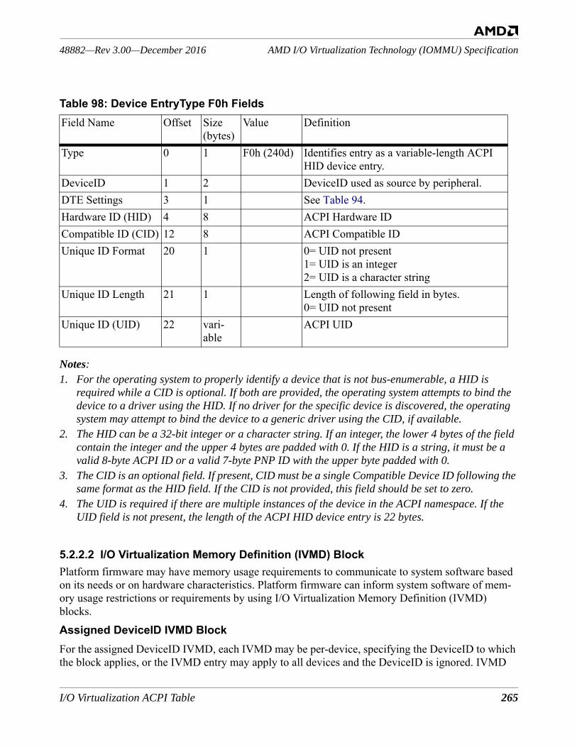
I/O Virtualization ACPI Table 265
AMD I/O Virtualization Technology (IOMMU) Specification48882—Rev 3.00—December 2016
Notes:1. For the operating system to properly identify a device that is not bus-enumerable, a HID is
required while a CID is optional. If both are provided, the operating system attempts to bind the device to a driver using the HID. If no driver for the specific device is discovered, the operating system may attempt to bind the device to a generic driver using the CID, if available.
2. The HID can be a 32-bit integer or a character string. If an integer, the lower 4 bytes of the field contain the integer and the upper 4 bytes are padded with 0. If the HID is a string, it must be a valid 8-byte ACPI ID or a valid 7-byte PNP ID with the upper byte padded with 0.
3. The CID is an optional field. If present, CID must be a single Compatible Device ID following the same format as the HID field. If the CID is not provided, this field should be set to zero.
4. The UID is required if there are multiple instances of the device in the ACPI namespace. If the UID field is not present, the length of the ACPI HID device entry is 22 bytes.
5.2.2.2 I/O Virtualization Memory Definition (IVMD) BlockPlatform firmware may have memory usage requirements to communicate to system software based on its needs or on hardware characteristics. Platform firmware can inform system software of mem-ory usage restrictions or requirements by using I/O Virtualization Memory Definition (IVMD) blocks. Assigned DeviceID IVMD BlockFor the assigned DeviceID IVMD, each IVMD may be per-device, specifying the DeviceID to which the block applies, or the IVMD entry may apply to all devices and the DeviceID is ignored. IVMD
Table 98: Device EntryType F0h FieldsField Name Offset Size
(bytes)Value Definition
Type 0 1 F0h (240d) Identifies entry as a variable-length ACPI HID device entry.
DeviceID 1 2 DeviceID used as source by peripheral.DTE Settings 3 1 See Table 94.Hardware ID (HID) 4 8 ACPI Hardware IDCompatible ID (CID) 12 8 ACPI Compatible IDUnique ID Format 20 1 0= UID not present
1= UID is an integer2= UID is a character string
Unique ID Length 21 1 Length of following field in bytes.0= UID not present
Unique ID (UID) 22 vari-able
ACPI UID
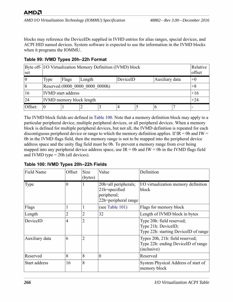
266 I/O Virtualization ACPI Table
48882—Rev 3.00—December 2016AMD I/O Virtualization Technology (IOMMU) Specification
blocks may reference the DeviceIDs supplied in IVHD entries for alias ranges, special devices, and ACPI HID named devices. System software is expected to use the information in the IVMD blocks when it programs the IOMMU.
The IVMD block fields are defined in Table 100. Note that a memory definition block may apply to a particular peripheral device, multiple peripheral devices, or all peripheral devices. When a memory block is defined for multiple peripheral devices, but not all, the IVMD definition is repeated for each discontiguous peripheral device or range to which the memory definition applies. If IR = 0b and IW = 0b in the IVMD flags field, then the memory range is not to be mapped into the peripheral device address space and the unity flag field must be 0b. To prevent a memory range from ever being mapped into any peripheral device address space, use IR = 0b and IW = 0b in the IVMD flags field and IVMD type = 20h (all devices).
Table 99: IVMD Types 20h–22h FormatByte off-set
I/O Virtualization Memory Definition (IVMD) block Relative offset
0 Type Flags Length DeviceID Auxiliary data +08 Reserved (0000_0000_0000_0000h) +816 IVMD start address +1624 IVMD memory block length +24Offset: 0 1 2 3 4 5 6 7 -
Table 100: IVMD Types 20h–22h FieldsField Name Offset Size
(bytes)Value Definition
Type 0 1 20h=all peripherals;21h=specified peripheral;22h=peripheral range
I/O virtualization memory definition block
Flags 1 1 (see Table 101) Flags for memory block Length 2 2 32 Length of IVMD block in bytesDeviceID 4 2 Type 20h: field reserved;
Type 21h: DeviceID;Type 22h: starting DeviceID of range
Auxiliary data 6 2 Types 20h, 21h: field reserved;Type 22h: ending DeviceID of range (inclusive)
Reserved 8 8 0 ReservedStart address 16 8 System Physical Address of start of
memory block
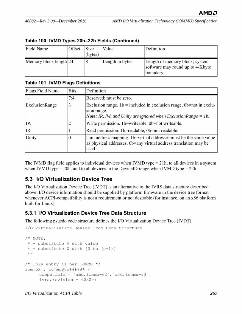
I/O Virtualization ACPI Table 267
AMD I/O Virtualization Technology (IOMMU) Specification48882—Rev 3.00—December 2016
The IVMD flag field applies to individual devices when IVMD type = 21h, to all devices in a system when IVMD type = 20h, and to all devices in the DeviceID range when IVMD type = 22h.
5.3 I/O Virtualization Device TreeThe I/O Virtualization Device Tree (IVDT) is an alternative to the IVRS data structure described above. I/O device information should be supplied by platform firmware in the device tree format whenever ACPI-compatibility is not a requirement or not desirable (for instance, on an x86 platform built for Linux).
5.3.1 I/O Virtualization Device Tree Data StructureThe following psuedo code structure defines the I/O Virtualization Device Tree (IVDT):I/O Virtualization Device Tree Data Structure
/* NOTE: * - substitute # with value * - substitute X with [0 to (n-1)] */
/* This entry is per IOMMU */iommuX : iommu@0x###### {
compatible = "amd,iommu-v2","amd,iommu-v3";ivrs,revision = <0x2>;
Memory block length 24 8 Length in bytes Length of memory block; system software may round up to 4-Kbyte boundary
Table 101: IVMD Flags DefinitionsFlags Field Name Bits Definition— 7:4 Reserved; must be zero.ExclusionRange 3 Exclusion range. 1b = included in exclusion range, 0b=not in exclu-
sion range.Note: IR, IW, and Unity are ignored when ExclusionRange = 1b.
IW 2 Write permission. 1b=writeable, 0b=not writeable.IR 1 Read permission. 1b=readable, 0b=not readable.Unity 0 Unit address mapping. 1b=virtual addresses must be the same value
as physical addresses. 0b=any virtual address translation may be used.
Table 100: IVMD Types 20h–22h Fields (Continued)Field Name Offset Size
(bytes)Value Definition
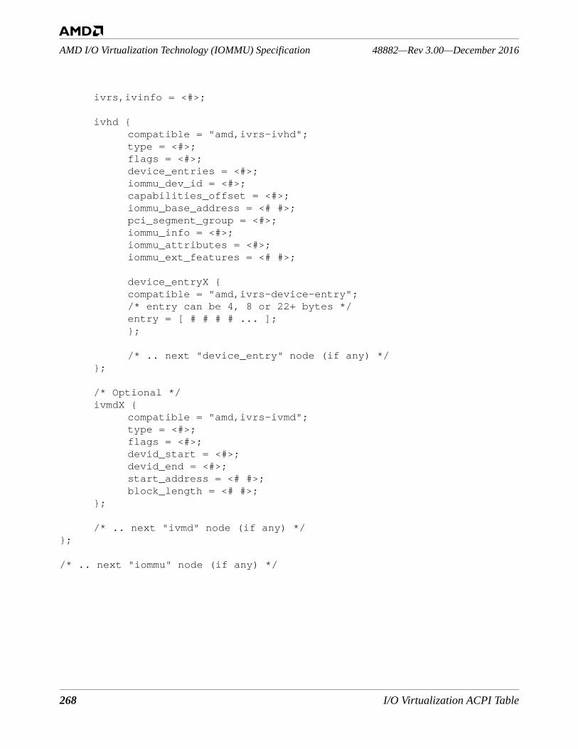
268 I/O Virtualization ACPI Table
48882—Rev 3.00—December 2016AMD I/O Virtualization Technology (IOMMU) Specification
ivrs,ivinfo = <#>;
ivhd {compatible = "amd,ivrs-ivhd";type = <#>;flags = <#>;device_entries = <#>;iommu_dev_id = <#>;capabilities_offset = <#>;iommu_base_address = <# #>;pci_segment_group = <#>;iommu_info = <#>;iommu_attributes = <#>;iommu_ext_features = <# #>;
device_entryX {compatible = "amd,ivrs-device-entry";/* entry can be 4, 8 or 22+ bytes */entry = [ # # # # ... ];};
/* .. next "device_entry" node (if any) */};
/* Optional */ivmdX {
compatible = "amd,ivrs-ivmd";type = <#>;flags = <#>;devid_start = <#>;devid_end = <#>;start_address = <# #>;block_length = <# #>;
};
/* .. next "ivmd" node (if any) */};
/* .. next "iommu" node (if any) */
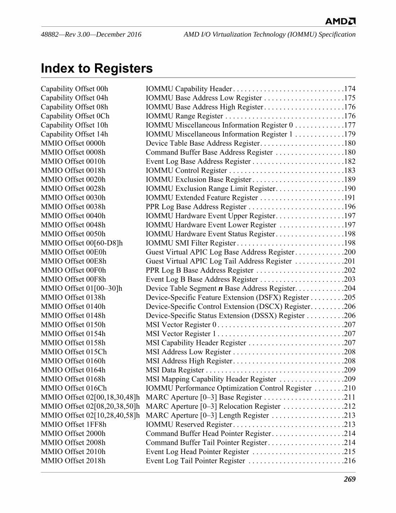
269
AMD I/O Virtualization Technology (IOMMU) Specification48882—Rev 3.00—December 2016
Index to RegistersCapability Offset 00h IOMMU Capability Header . . . . . . . . . . . . . . . . . . . . . . . . . . . . .174Capability Offset 04h IOMMU Base Address Low Register . . . . . . . . . . . . . . . . . . . . .175Capability Offset 08h IOMMU Base Address High Register . . . . . . . . . . . . . . . . . . . . .176Capability Offset 0Ch IOMMU Range Register . . . . . . . . . . . . . . . . . . . . . . . . . . . . . . .176Capability Offset 10h IOMMU Miscellaneous Information Register 0 . . . . . . . . . . . . .177Capability Offset 14h IOMMU Miscellaneous Information Register 1 . . . . . . . . . . . . .179MMIO Offset 0000h Device Table Base Address Register. . . . . . . . . . . . . . . . . . . . . .180MMIO Offset 0008h Command Buffer Base Address Register . . . . . . . . . . . . . . . . . .180MMIO Offset 0010h Event Log Base Address Register . . . . . . . . . . . . . . . . . . . . . . . .182MMIO Offset 0018h IOMMU Control Register . . . . . . . . . . . . . . . . . . . . . . . . . . . . . .183MMIO Offset 0020h IOMMU Exclusion Base Register . . . . . . . . . . . . . . . . . . . . . . . .189MMIO Offset 0028h IOMMU Exclusion Range Limit Register. . . . . . . . . . . . . . . . . .190MMIO Offset 0030h IOMMU Extended Feature Register . . . . . . . . . . . . . . . . . . . . . .191MMIO Offset 0038h PPR Log Base Address Register . . . . . . . . . . . . . . . . . . . . . . . . .196MMIO Offset 0040h IOMMU Hardware Event Upper Register. . . . . . . . . . . . . . . . . .197MMIO Offset 0048h IOMMU Hardware Event Lower Register . . . . . . . . . . . . . . . . .197MMIO Offset 0050h IOMMU Hardware Event Status Register . . . . . . . . . . . . . . . . . .198MMIO Offset 00[60-D8]h IOMMU SMI Filter Register . . . . . . . . . . . . . . . . . . . . . . . . . . . .198MMIO Offset 00E0h Guest Virtual APIC Log Base Address Register . . . . . . . . . . . . .200MMIO Offset 00E8h Guest Virtual APIC Log Tail Address Register . . . . . . . . . . . . .201MMIO Offset 00F0h PPR Log B Base Address Register . . . . . . . . . . . . . . . . . . . . . . .202MMIO Offset 00F8h Event Log B Base Address Register . . . . . . . . . . . . . . . . . . . . . .203MMIO Offset 01[00–30]h Device Table Segment n Base Address Register. . . . . . . . . . . . .204MMIO Offset 0138h Device-Specific Feature Extension (DSFX) Register . . . . . . . . .205MMIO Offset 0140h Device-Specific Control Extension (DSCX) Register. . . . . . . . .206MMIO Offset 0148h Device-Specific Status Extension (DSSX) Register . . . . . . . . . .206MMIO Offset 0150h MSI Vector Register 0 . . . . . . . . . . . . . . . . . . . . . . . . . . . . . . . . .207MMIO Offset 0154h MSI Vector Register 1 . . . . . . . . . . . . . . . . . . . . . . . . . . . . . . . . .207MMIO Offset 0158h MSI Capability Header Register . . . . . . . . . . . . . . . . . . . . . . . . .207MMIO Offset 015Ch MSI Address Low Register . . . . . . . . . . . . . . . . . . . . . . . . . . . . .208MMIO Offset 0160h MSI Address High Register . . . . . . . . . . . . . . . . . . . . . . . . . . . . .208MMIO Offset 0164h MSI Data Register . . . . . . . . . . . . . . . . . . . . . . . . . . . . . . . . . . . .209MMIO Offset 0168h MSI Mapping Capability Header Register . . . . . . . . . . . . . . . . .209MMIO Offset 016Ch IOMMU Performance Optimization Control Register . . . . . . . .210MMIO Offset 02[00,18,30,48]h MARC Aperture [0–3] Base Register . . . . . . . . . . . . . . . . . . . . .211MMIO Offset 02[08,20,38,50]h MARC Aperture [0–3] Relocation Register . . . . . . . . . . . . . . . .212MMIO Offset 02[10,28,40,58]h MARC Aperture [0–3] Length Register . . . . . . . . . . . . . . . . . . .213MMIO Offset 1FF8h IOMMU Reserved Register . . . . . . . . . . . . . . . . . . . . . . . . . . . . .213MMIO Offset 2000h Command Buffer Head Pointer Register . . . . . . . . . . . . . . . . . . .214MMIO Offset 2008h Command Buffer Tail Pointer Register . . . . . . . . . . . . . . . . . . . .214MMIO Offset 2010h Event Log Head Pointer Register . . . . . . . . . . . . . . . . . . . . . . . .215MMIO Offset 2018h Event Log Tail Pointer Register . . . . . . . . . . . . . . . . . . . . . . . . .216
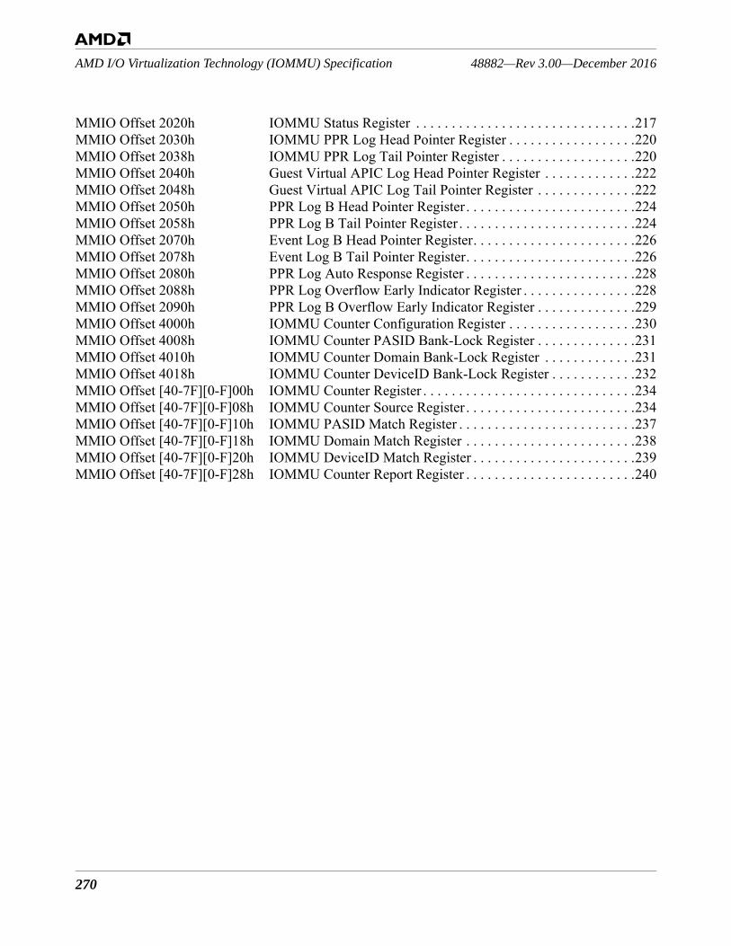
270
48882—Rev 3.00—December 2016AMD I/O Virtualization Technology (IOMMU) Specification
MMIO Offset 2020h IOMMU Status Register . . . . . . . . . . . . . . . . . . . . . . . . . . . . . . .217MMIO Offset 2030h IOMMU PPR Log Head Pointer Register . . . . . . . . . . . . . . . . . .220MMIO Offset 2038h IOMMU PPR Log Tail Pointer Register . . . . . . . . . . . . . . . . . . .220MMIO Offset 2040h Guest Virtual APIC Log Head Pointer Register . . . . . . . . . . . . .222MMIO Offset 2048h Guest Virtual APIC Log Tail Pointer Register . . . . . . . . . . . . . .222MMIO Offset 2050h PPR Log B Head Pointer Register . . . . . . . . . . . . . . . . . . . . . . . .224MMIO Offset 2058h PPR Log B Tail Pointer Register . . . . . . . . . . . . . . . . . . . . . . . . .224MMIO Offset 2070h Event Log B Head Pointer Register. . . . . . . . . . . . . . . . . . . . . . .226MMIO Offset 2078h Event Log B Tail Pointer Register. . . . . . . . . . . . . . . . . . . . . . . .226MMIO Offset 2080h PPR Log Auto Response Register . . . . . . . . . . . . . . . . . . . . . . . .228MMIO Offset 2088h PPR Log Overflow Early Indicator Register . . . . . . . . . . . . . . . .228MMIO Offset 2090h PPR Log B Overflow Early Indicator Register . . . . . . . . . . . . . .229MMIO Offset 4000h IOMMU Counter Configuration Register . . . . . . . . . . . . . . . . . .230MMIO Offset 4008h IOMMU Counter PASID Bank-Lock Register . . . . . . . . . . . . . .231MMIO Offset 4010h IOMMU Counter Domain Bank-Lock Register . . . . . . . . . . . . .231MMIO Offset 4018h IOMMU Counter DeviceID Bank-Lock Register . . . . . . . . . . . .232MMIO Offset [40-7F][0-F]00h IOMMU Counter Register . . . . . . . . . . . . . . . . . . . . . . . . . . . . . .234MMIO Offset [40-7F][0-F]08h IOMMU Counter Source Register . . . . . . . . . . . . . . . . . . . . . . . .234MMIO Offset [40-7F][0-F]10h IOMMU PASID Match Register . . . . . . . . . . . . . . . . . . . . . . . . .237MMIO Offset [40-7F][0-F]18h IOMMU Domain Match Register . . . . . . . . . . . . . . . . . . . . . . . .238MMIO Offset [40-7F][0-F]20h IOMMU DeviceID Match Register . . . . . . . . . . . . . . . . . . . . . . .239MMIO Offset [40-7F][0-F]28h IOMMU Counter Report Register . . . . . . . . . . . . . . . . . . . . . . . .240