amd64 architecture programmer’s manual, volume 1...
TRANSCRIPT

Advanced Micro Devices
AMD64 Technology
AMD64 ArchitectureProgrammer’s Manual
Volume 1:Application Programming
Publication No. Revision Date24592 3.20 May 2013

AMD64 Technology 24592—Rev. 3.20—May 2013
Trademarks
AMD, the AMD Arrow logo, AMD Athlon, and AMD Opteron, and combinations thereof, and 3DNow! are trademarks,and AMD-K6 is a registered trademark of Advanced Micro Devices, Inc.
MMX is a trademark and Pentium is a registered trademark of Intel Corporation.
Other product names used in this publication are for identification purposes only and may be trademarks of theirrespective companies.
© 2002 – 2013 Advanced Micro Devices, Inc. All rights reserved.
The contents of this document are provided in connection with Advanced MicroDevices, Inc. (“AMD”) products. AMD makes no representations or warranties withrespect to the accuracy or completeness of the contents of this publication andreserves the right to make changes to specifications and product descriptions atany time without notice. The information contained herein may be of a preliminaryor advance nature and is subject to change without notice. No license, whetherexpress, implied, arising by estoppel or otherwise, to any intellectual property rightsis granted by this publication. Except as set forth in AMD’s Standard Terms andConditions of Sale, AMD assumes no liability whatsoever, and disclaims anyexpress or implied warranty, relating to its products including, but not limited to, theimplied warranty of merchantability, fitness for a particular purpose, or infringementof any intellectual property right.
AMD’s products are not designed, intended, authorized or warranted for use ascomponents in systems intended for surgical implant into the body, or in other appli-cations intended to support or sustain life, or in any other application in which thefailure of AMD’s product could create a situation where personal injury, death, orsevere property or environmental damage may occur. AMD reserves the right todiscontinue or make changes to its products at any time without notice.
Contents i
24592—Rev. 3.20—May 2013 AMD64 Technology
Contents
Contents . . . . . . . . . . . . . . . . . . . . . . . . . . . . . . . . . . . . . . . . . . . . . . . . . . . . . . . . . . . . . . . . . . . . . . . i
Figures. . . . . . . . . . . . . . . . . . . . . . . . . . . . . . . . . . . . . . . . . . . . . . . . . . . . . . . . . . . . . . . . . . . . . . . . ix
Tables . . . . . . . . . . . . . . . . . . . . . . . . . . . . . . . . . . . . . . . . . . . . . . . . . . . . . . . . . . . . . . . . . . . . . . . xiii
Revision History . . . . . . . . . . . . . . . . . . . . . . . . . . . . . . . . . . . . . . . . . . . . . . . . . . . . . . . . . . . . . . . . xv
Preface. . . . . . . . . . . . . . . . . . . . . . . . . . . . . . . . . . . . . . . . . . . . . . . . . . . . . . . . . . . . . . . . . . . . . . . xviiAbout This Book. . . . . . . . . . . . . . . . . . . . . . . . . . . . . . . . . . . . . . . . . . . . . . . . . . . . . . . . . . . . . . . . . xviiAudience . . . . . . . . . . . . . . . . . . . . . . . . . . . . . . . . . . . . . . . . . . . . . . . . . . . . . . . . . . . . . . . . . . . . . . . xviiOrganization . . . . . . . . . . . . . . . . . . . . . . . . . . . . . . . . . . . . . . . . . . . . . . . . . . . . . . . . . . . . . . . . . . . . xviiConventions and Definitions . . . . . . . . . . . . . . . . . . . . . . . . . . . . . . . . . . . . . . . . . . . . . . . . . . . . . . xviii
Notational Conventions . . . . . . . . . . . . . . . . . . . . . . . . . . . . . . . . . . . . . . . . . . . . . . . . . . . xviiiDefinitions . . . . . . . . . . . . . . . . . . . . . . . . . . . . . . . . . . . . . . . . . . . . . . . . . . . . . . . . . . . . . . xixRegisters . . . . . . . . . . . . . . . . . . . . . . . . . . . . . . . . . . . . . . . . . . . . . . . . . . . . . . . . . . . . . . . xxviiEndian Order . . . . . . . . . . . . . . . . . . . . . . . . . . . . . . . . . . . . . . . . . . . . . . . . . . . . . . . . . . . . xxix
Related Documents . . . . . . . . . . . . . . . . . . . . . . . . . . . . . . . . . . . . . . . . . . . . . . . . . . . . . . . . . . . . . . xxix
1 Overview of the AMD64 Architecture . . . . . . . . . . . . . . . . . . . . . . . . . . . . . . . . . . . . . . . . . .11.1 Introduction . . . . . . . . . . . . . . . . . . . . . . . . . . . . . . . . . . . . . . . . . . . . . . . . . . . . . . . . . . . . . . . . 1
1.1.1 AMD64 Features . . . . . . . . . . . . . . . . . . . . . . . . . . . . . . . . . . . . . . . . . . . . . . . . . . . . . . . 11.1.2 Registers . . . . . . . . . . . . . . . . . . . . . . . . . . . . . . . . . . . . . . . . . . . . . . . . . . . . . . . . . . . . . . 31.1.3 Instruction Set . . . . . . . . . . . . . . . . . . . . . . . . . . . . . . . . . . . . . . . . . . . . . . . . . . . . . . . . . . 41.1.4 Media Instructions . . . . . . . . . . . . . . . . . . . . . . . . . . . . . . . . . . . . . . . . . . . . . . . . . . . . . . 41.1.5 Floating-Point Instructions . . . . . . . . . . . . . . . . . . . . . . . . . . . . . . . . . . . . . . . . . . . . . . . . 5
1.2 Modes of Operation . . . . . . . . . . . . . . . . . . . . . . . . . . . . . . . . . . . . . . . . . . . . . . . . . . . . . . . . . . 61.2.1 Long Mode . . . . . . . . . . . . . . . . . . . . . . . . . . . . . . . . . . . . . . . . . . . . . . . . . . . . . . . . . . . . 61.2.2 64-Bit Mode . . . . . . . . . . . . . . . . . . . . . . . . . . . . . . . . . . . . . . . . . . . . . . . . . . . . . . . . . . . 61.2.3 Compatibility Mode . . . . . . . . . . . . . . . . . . . . . . . . . . . . . . . . . . . . . . . . . . . . . . . . . . . . . 71.2.4 Legacy Mode . . . . . . . . . . . . . . . . . . . . . . . . . . . . . . . . . . . . . . . . . . . . . . . . . . . . . . . . . . 7
2 Memory Model . . . . . . . . . . . . . . . . . . . . . . . . . . . . . . . . . . . . . . . . . . . . . . . . . . . . . . . . . . . . .92.1 Memory Organization . . . . . . . . . . . . . . . . . . . . . . . . . . . . . . . . . . . . . . . . . . . . . . . . . . . . . . . . 9
2.1.1 Virtual Memory . . . . . . . . . . . . . . . . . . . . . . . . . . . . . . . . . . . . . . . . . . . . . . . . . . . . . . . . 92.1.2 Segment Registers . . . . . . . . . . . . . . . . . . . . . . . . . . . . . . . . . . . . . . . . . . . . . . . . . . . . . 102.1.3 Physical Memory . . . . . . . . . . . . . . . . . . . . . . . . . . . . . . . . . . . . . . . . . . . . . . . . . . . . . . 112.1.4 Memory Management. . . . . . . . . . . . . . . . . . . . . . . . . . . . . . . . . . . . . . . . . . . . . . . . . . . 11
2.2 Memory Addressing . . . . . . . . . . . . . . . . . . . . . . . . . . . . . . . . . . . . . . . . . . . . . . . . . . . . . . . . 142.2.1 Byte Ordering . . . . . . . . . . . . . . . . . . . . . . . . . . . . . . . . . . . . . . . . . . . . . . . . . . . . . . . . . 142.2.2 64-Bit Canonical Addresses . . . . . . . . . . . . . . . . . . . . . . . . . . . . . . . . . . . . . . . . . . . . . . 152.2.3 Effective Addresses . . . . . . . . . . . . . . . . . . . . . . . . . . . . . . . . . . . . . . . . . . . . . . . . . . . . 152.2.4 Address-Size Prefix . . . . . . . . . . . . . . . . . . . . . . . . . . . . . . . . . . . . . . . . . . . . . . . . . . . . 172.2.5 RIP-Relative Addressing . . . . . . . . . . . . . . . . . . . . . . . . . . . . . . . . . . . . . . . . . . . . . . . . 18
2.3 Pointers . . . . . . . . . . . . . . . . . . . . . . . . . . . . . . . . . . . . . . . . . . . . . . . . . . . . . . . . . . . . . . . . . . 192.3.1 Near and Far Pointers . . . . . . . . . . . . . . . . . . . . . . . . . . . . . . . . . . . . . . . . . . . . . . . . . . . 19
2.4 Stack Operation . . . . . . . . . . . . . . . . . . . . . . . . . . . . . . . . . . . . . . . . . . . . . . . . . . . . . . . . . . . . 19

ii Contents
AMD64 Technology 24592—Rev. 3.20—May 2013
2.5 Instruction Pointer . . . . . . . . . . . . . . . . . . . . . . . . . . . . . . . . . . . . . . . . . . . . . . . . . . . . . . . . . . 20
3 General-Purpose Programming . . . . . . . . . . . . . . . . . . . . . . . . . . . . . . . . . . . . . . . . . . . . . .233.1 Registers . . . . . . . . . . . . . . . . . . . . . . . . . . . . . . . . . . . . . . . . . . . . . . . . . . . . . . . . . . . . . . . . . 23
3.1.1 Legacy Registers. . . . . . . . . . . . . . . . . . . . . . . . . . . . . . . . . . . . . . . . . . . . . . . . . . . . . . . 243.1.2 64-Bit-Mode Registers . . . . . . . . . . . . . . . . . . . . . . . . . . . . . . . . . . . . . . . . . . . . . . . . . . 263.1.3 Implicit Uses of GPRs . . . . . . . . . . . . . . . . . . . . . . . . . . . . . . . . . . . . . . . . . . . . . . . . . . 303.1.4 Flags Register . . . . . . . . . . . . . . . . . . . . . . . . . . . . . . . . . . . . . . . . . . . . . . . . . . . . . . . . . 343.1.5 Instruction Pointer Register . . . . . . . . . . . . . . . . . . . . . . . . . . . . . . . . . . . . . . . . . . . . . . 36
3.2 Operands . . . . . . . . . . . . . . . . . . . . . . . . . . . . . . . . . . . . . . . . . . . . . . . . . . . . . . . . . . . . . . . . . 363.2.1 Fundamental Data Types . . . . . . . . . . . . . . . . . . . . . . . . . . . . . . . . . . . . . . . . . . . . . . . . 363.2.2 General-Purpose Instruction Data types . . . . . . . . . . . . . . . . . . . . . . . . . . . . . . . . . . . . . 383.2.3 Operand Sizes and Overrides . . . . . . . . . . . . . . . . . . . . . . . . . . . . . . . . . . . . . . . . . . . . . 413.2.4 Operand Addressing . . . . . . . . . . . . . . . . . . . . . . . . . . . . . . . . . . . . . . . . . . . . . . . . . . . . 433.2.5 Data Alignment. . . . . . . . . . . . . . . . . . . . . . . . . . . . . . . . . . . . . . . . . . . . . . . . . . . . . . . . 43
3.3 Instruction Summary . . . . . . . . . . . . . . . . . . . . . . . . . . . . . . . . . . . . . . . . . . . . . . . . . . . . . . . . 443.3.1 Syntax . . . . . . . . . . . . . . . . . . . . . . . . . . . . . . . . . . . . . . . . . . . . . . . . . . . . . . . . . . . . . . . 443.3.2 Data Transfer . . . . . . . . . . . . . . . . . . . . . . . . . . . . . . . . . . . . . . . . . . . . . . . . . . . . . . . . . 453.3.3 Data Conversion . . . . . . . . . . . . . . . . . . . . . . . . . . . . . . . . . . . . . . . . . . . . . . . . . . . . . . . 493.3.4 Load Segment Registers . . . . . . . . . . . . . . . . . . . . . . . . . . . . . . . . . . . . . . . . . . . . . . . . . 523.3.5 Load Effective Address . . . . . . . . . . . . . . . . . . . . . . . . . . . . . . . . . . . . . . . . . . . . . . . . . 523.3.6 Arithmetic . . . . . . . . . . . . . . . . . . . . . . . . . . . . . . . . . . . . . . . . . . . . . . . . . . . . . . . . . . . . 533.3.7 Rotate and Shift . . . . . . . . . . . . . . . . . . . . . . . . . . . . . . . . . . . . . . . . . . . . . . . . . . . . . . . 553.3.8 Bit Manipulation. . . . . . . . . . . . . . . . . . . . . . . . . . . . . . . . . . . . . . . . . . . . . . . . . . . . . . . 563.3.9 Compare and Test . . . . . . . . . . . . . . . . . . . . . . . . . . . . . . . . . . . . . . . . . . . . . . . . . . . . . . 593.3.10 Logical . . . . . . . . . . . . . . . . . . . . . . . . . . . . . . . . . . . . . . . . . . . . . . . . . . . . . . . . . . . . . 613.3.11 String. . . . . . . . . . . . . . . . . . . . . . . . . . . . . . . . . . . . . . . . . . . . . . . . . . . . . . . . . . . . . . . 623.3.12 Control Transfer . . . . . . . . . . . . . . . . . . . . . . . . . . . . . . . . . . . . . . . . . . . . . . . . . . . . . . 633.3.13 Flags . . . . . . . . . . . . . . . . . . . . . . . . . . . . . . . . . . . . . . . . . . . . . . . . . . . . . . . . . . . . . . . 673.3.14 Input/Output . . . . . . . . . . . . . . . . . . . . . . . . . . . . . . . . . . . . . . . . . . . . . . . . . . . . . . . . . 683.3.15 Semaphores. . . . . . . . . . . . . . . . . . . . . . . . . . . . . . . . . . . . . . . . . . . . . . . . . . . . . . . . . . 693.3.16 Processor Information. . . . . . . . . . . . . . . . . . . . . . . . . . . . . . . . . . . . . . . . . . . . . . . . . . 703.3.17 Cache and Memory Management . . . . . . . . . . . . . . . . . . . . . . . . . . . . . . . . . . . . . . . . . 713.3.18 No Operation . . . . . . . . . . . . . . . . . . . . . . . . . . . . . . . . . . . . . . . . . . . . . . . . . . . . . . . . 713.3.19 System Calls . . . . . . . . . . . . . . . . . . . . . . . . . . . . . . . . . . . . . . . . . . . . . . . . . . . . . . . . . 723.3.20 Application-Targeted Accelerator Instructions. . . . . . . . . . . . . . . . . . . . . . . . . . . . . . . 72
3.4 General Rules for Instructions in 64-Bit Mode . . . . . . . . . . . . . . . . . . . . . . . . . . . . . . . . . . . . 723.4.1 Address Size . . . . . . . . . . . . . . . . . . . . . . . . . . . . . . . . . . . . . . . . . . . . . . . . . . . . . . . . . . 723.4.2 Canonical Address Format . . . . . . . . . . . . . . . . . . . . . . . . . . . . . . . . . . . . . . . . . . . . . . . 733.4.3 Branch-Displacement Size . . . . . . . . . . . . . . . . . . . . . . . . . . . . . . . . . . . . . . . . . . . . . . . 733.4.4 Operand Size. . . . . . . . . . . . . . . . . . . . . . . . . . . . . . . . . . . . . . . . . . . . . . . . . . . . . . . . . . 733.4.5 High 32 Bits . . . . . . . . . . . . . . . . . . . . . . . . . . . . . . . . . . . . . . . . . . . . . . . . . . . . . . . . . . 733.4.6 Invalid and Reassigned Instructions . . . . . . . . . . . . . . . . . . . . . . . . . . . . . . . . . . . . . . . . 743.4.7 Instructions with 64-Bit Default Operand Size . . . . . . . . . . . . . . . . . . . . . . . . . . . . . . . 75
3.5 Instruction Prefixes . . . . . . . . . . . . . . . . . . . . . . . . . . . . . . . . . . . . . . . . . . . . . . . . . . . . . . . . . 763.5.1 Legacy Prefixes . . . . . . . . . . . . . . . . . . . . . . . . . . . . . . . . . . . . . . . . . . . . . . . . . . . . . . . 763.5.2 REX Prefixes . . . . . . . . . . . . . . . . . . . . . . . . . . . . . . . . . . . . . . . . . . . . . . . . . . . . . . . . . 793.5.3 VEX and XOP Prefixes . . . . . . . . . . . . . . . . . . . . . . . . . . . . . . . . . . . . . . . . . . . . . . . . . 79

Contents iii
24592—Rev. 3.20—May 2013 AMD64 Technology
3.6 Feature Detection. . . . . . . . . . . . . . . . . . . . . . . . . . . . . . . . . . . . . . . . . . . . . . . . . . . . . . . . . . . 793.6.1 Feature Detection in a Virtualized Environment . . . . . . . . . . . . . . . . . . . . . . . . . . . . . . 80
3.7 Control Transfers . . . . . . . . . . . . . . . . . . . . . . . . . . . . . . . . . . . . . . . . . . . . . . . . . . . . . . . . . . . 803.7.1 Overview. . . . . . . . . . . . . . . . . . . . . . . . . . . . . . . . . . . . . . . . . . . . . . . . . . . . . . . . . . . . . 803.7.2 Privilege Levels . . . . . . . . . . . . . . . . . . . . . . . . . . . . . . . . . . . . . . . . . . . . . . . . . . . . . . . 813.7.3 Procedure Stack . . . . . . . . . . . . . . . . . . . . . . . . . . . . . . . . . . . . . . . . . . . . . . . . . . . . . . . 813.7.4 Jumps . . . . . . . . . . . . . . . . . . . . . . . . . . . . . . . . . . . . . . . . . . . . . . . . . . . . . . . . . . . . . . . 823.7.5 Procedure Calls . . . . . . . . . . . . . . . . . . . . . . . . . . . . . . . . . . . . . . . . . . . . . . . . . . . . . . . . 833.7.6 Returning from Procedures. . . . . . . . . . . . . . . . . . . . . . . . . . . . . . . . . . . . . . . . . . . . . . . 863.7.7 System Calls . . . . . . . . . . . . . . . . . . . . . . . . . . . . . . . . . . . . . . . . . . . . . . . . . . . . . . . . . . 883.7.8 General Considerations for Branching . . . . . . . . . . . . . . . . . . . . . . . . . . . . . . . . . . . . . . 883.7.9 Branching in 64-Bit Mode . . . . . . . . . . . . . . . . . . . . . . . . . . . . . . . . . . . . . . . . . . . . . . . 893.7.10 Interrupts and Exceptions . . . . . . . . . . . . . . . . . . . . . . . . . . . . . . . . . . . . . . . . . . . . . . . 90
3.8 Input/Output. . . . . . . . . . . . . . . . . . . . . . . . . . . . . . . . . . . . . . . . . . . . . . . . . . . . . . . . . . . . . . . 943.8.1 I/O Addressing . . . . . . . . . . . . . . . . . . . . . . . . . . . . . . . . . . . . . . . . . . . . . . . . . . . . . . . . 943.8.2 I/O Ordering . . . . . . . . . . . . . . . . . . . . . . . . . . . . . . . . . . . . . . . . . . . . . . . . . . . . . . . . . . 953.8.3 Protected-Mode I/O . . . . . . . . . . . . . . . . . . . . . . . . . . . . . . . . . . . . . . . . . . . . . . . . . . . . 96
3.9 Memory Optimization . . . . . . . . . . . . . . . . . . . . . . . . . . . . . . . . . . . . . . . . . . . . . . . . . . . . . . . 973.9.1 Accessing Memory . . . . . . . . . . . . . . . . . . . . . . . . . . . . . . . . . . . . . . . . . . . . . . . . . . . . . 973.9.2 Forcing Memory Order. . . . . . . . . . . . . . . . . . . . . . . . . . . . . . . . . . . . . . . . . . . . . . . . . . 983.9.3 Caches. . . . . . . . . . . . . . . . . . . . . . . . . . . . . . . . . . . . . . . . . . . . . . . . . . . . . . . . . . . . . . 1003.9.4 Cache Operation . . . . . . . . . . . . . . . . . . . . . . . . . . . . . . . . . . . . . . . . . . . . . . . . . . . . . . 1013.9.5 Cache Pollution. . . . . . . . . . . . . . . . . . . . . . . . . . . . . . . . . . . . . . . . . . . . . . . . . . . . . . . 1023.9.6 Cache-Control Instructions . . . . . . . . . . . . . . . . . . . . . . . . . . . . . . . . . . . . . . . . . . . . . . 103
3.10 Performance Considerations . . . . . . . . . . . . . . . . . . . . . . . . . . . . . . . . . . . . . . . . . . . . . . . . . 1053.10.1 Use Large Operand Sizes . . . . . . . . . . . . . . . . . . . . . . . . . . . . . . . . . . . . . . . . . . . . . . 1053.10.2 Use Short Instructions. . . . . . . . . . . . . . . . . . . . . . . . . . . . . . . . . . . . . . . . . . . . . . . . . 1053.10.3 Align Data. . . . . . . . . . . . . . . . . . . . . . . . . . . . . . . . . . . . . . . . . . . . . . . . . . . . . . . . . . 1053.10.4 Avoid Branches. . . . . . . . . . . . . . . . . . . . . . . . . . . . . . . . . . . . . . . . . . . . . . . . . . . . . . 1063.10.5 Prefetch Data . . . . . . . . . . . . . . . . . . . . . . . . . . . . . . . . . . . . . . . . . . . . . . . . . . . . . . . 1063.10.6 Keep Common Operands in Registers . . . . . . . . . . . . . . . . . . . . . . . . . . . . . . . . . . . . 1063.10.7 Avoid True Dependencies. . . . . . . . . . . . . . . . . . . . . . . . . . . . . . . . . . . . . . . . . . . . . . 1063.10.8 Avoid Store-to-Load Dependencies . . . . . . . . . . . . . . . . . . . . . . . . . . . . . . . . . . . . . . 1063.10.9 Optimize Stack Allocation . . . . . . . . . . . . . . . . . . . . . . . . . . . . . . . . . . . . . . . . . . . . . 1063.10.10 Consider Repeat-Prefix Setup Time . . . . . . . . . . . . . . . . . . . . . . . . . . . . . . . . . . . . . 1073.10.11 Replace GPR with Media Instructions . . . . . . . . . . . . . . . . . . . . . . . . . . . . . . . . . . . 1073.10.12 Organize Data in Memory Blocks . . . . . . . . . . . . . . . . . . . . . . . . . . . . . . . . . . . . . . 107
3.11 Cross-Modifying Code . . . . . . . . . . . . . . . . . . . . . . . . . . . . . . . . . . . . . . . . . . . . . . . . . . . . . 107
4 Streaming SIMD Extensions Media and Scientific Programming . . . . . . . . . . . . . . . . .1094.1 Overview . . . . . . . . . . . . . . . . . . . . . . . . . . . . . . . . . . . . . . . . . . . . . . . . . . . . . . . . . . . . . . . . 109
4.1.1 Capabilities . . . . . . . . . . . . . . . . . . . . . . . . . . . . . . . . . . . . . . . . . . . . . . . . . . . . . . . . . . 1094.1.2 Origins . . . . . . . . . . . . . . . . . . . . . . . . . . . . . . . . . . . . . . . . . . . . . . . . . . . . . . . . . . . . . 1104.1.3 Compatibility . . . . . . . . . . . . . . . . . . . . . . . . . . . . . . . . . . . . . . . . . . . . . . . . . . . . . . . . 110
4.2 Registers . . . . . . . . . . . . . . . . . . . . . . . . . . . . . . . . . . . . . . . . . . . . . . . . . . . . . . . . . . . . . . . . 1114.2.1 SSE Registers . . . . . . . . . . . . . . . . . . . . . . . . . . . . . . . . . . . . . . . . . . . . . . . . . . . . . . . . 1114.2.2 MXCSR Register . . . . . . . . . . . . . . . . . . . . . . . . . . . . . . . . . . . . . . . . . . . . . . . . . . . . . 1134.2.3 Other Data Registers. . . . . . . . . . . . . . . . . . . . . . . . . . . . . . . . . . . . . . . . . . . . . . . . . . . 115

iv Contents
AMD64 Technology 24592—Rev. 3.20—May 2013
4.2.4 Effect on rFLAGS Register . . . . . . . . . . . . . . . . . . . . . . . . . . . . . . . . . . . . . . . . . . . . . 1164.3 Operands . . . . . . . . . . . . . . . . . . . . . . . . . . . . . . . . . . . . . . . . . . . . . . . . . . . . . . . . . . . . . . . . 116
4.3.1 Operand Addressing . . . . . . . . . . . . . . . . . . . . . . . . . . . . . . . . . . . . . . . . . . . . . . . . . . . 1164.3.2 Data Alignment. . . . . . . . . . . . . . . . . . . . . . . . . . . . . . . . . . . . . . . . . . . . . . . . . . . . . . . 1184.3.3 SSE Instruction Data Types . . . . . . . . . . . . . . . . . . . . . . . . . . . . . . . . . . . . . . . . . . . . . 1194.3.4 Operand Sizes and Overrides . . . . . . . . . . . . . . . . . . . . . . . . . . . . . . . . . . . . . . . . . . . . 134
4.4 Vector Operations . . . . . . . . . . . . . . . . . . . . . . . . . . . . . . . . . . . . . . . . . . . . . . . . . . . . . . . . . 1344.4.1 Integer Vector Operations . . . . . . . . . . . . . . . . . . . . . . . . . . . . . . . . . . . . . . . . . . . . . . . 1344.4.2 Floating-Point Vector Operations . . . . . . . . . . . . . . . . . . . . . . . . . . . . . . . . . . . . . . . . . 135
4.5 Instruction Overview . . . . . . . . . . . . . . . . . . . . . . . . . . . . . . . . . . . . . . . . . . . . . . . . . . . . . . . 1364.5.1 Instruction Syntax. . . . . . . . . . . . . . . . . . . . . . . . . . . . . . . . . . . . . . . . . . . . . . . . . . . . . 1364.5.2 Mnemonics . . . . . . . . . . . . . . . . . . . . . . . . . . . . . . . . . . . . . . . . . . . . . . . . . . . . . . . . . . 1374.5.3 Move Operations . . . . . . . . . . . . . . . . . . . . . . . . . . . . . . . . . . . . . . . . . . . . . . . . . . . . . 1384.5.4 Data Conversion and Reordering . . . . . . . . . . . . . . . . . . . . . . . . . . . . . . . . . . . . . . . . . 1424.5.5 Matrix and Special Arithmetic Operations . . . . . . . . . . . . . . . . . . . . . . . . . . . . . . . . . . 1434.5.6 Branch Removal . . . . . . . . . . . . . . . . . . . . . . . . . . . . . . . . . . . . . . . . . . . . . . . . . . . . . . 145
4.6 Instruction Summary—Integer Instructions . . . . . . . . . . . . . . . . . . . . . . . . . . . . . . . . . . . . . 1474.6.1 Data Transfer . . . . . . . . . . . . . . . . . . . . . . . . . . . . . . . . . . . . . . . . . . . . . . . . . . . . . . . . 1484.6.2 Data Conversion . . . . . . . . . . . . . . . . . . . . . . . . . . . . . . . . . . . . . . . . . . . . . . . . . . . . . . 1534.6.3 Data Reordering . . . . . . . . . . . . . . . . . . . . . . . . . . . . . . . . . . . . . . . . . . . . . . . . . . . . . . 1554.6.4 Arithmetic . . . . . . . . . . . . . . . . . . . . . . . . . . . . . . . . . . . . . . . . . . . . . . . . . . . . . . . . . . . 1614.6.5 Enhanced Media . . . . . . . . . . . . . . . . . . . . . . . . . . . . . . . . . . . . . . . . . . . . . . . . . . . . . . 1664.6.6 Shift and Rotate . . . . . . . . . . . . . . . . . . . . . . . . . . . . . . . . . . . . . . . . . . . . . . . . . . . . . . 1714.6.7 Compare . . . . . . . . . . . . . . . . . . . . . . . . . . . . . . . . . . . . . . . . . . . . . . . . . . . . . . . . . . . . 1734.6.8 Logical . . . . . . . . . . . . . . . . . . . . . . . . . . . . . . . . . . . . . . . . . . . . . . . . . . . . . . . . . . . . . 1784.6.9 Save and Restore State . . . . . . . . . . . . . . . . . . . . . . . . . . . . . . . . . . . . . . . . . . . . . . . . . 179
4.7 Instruction Summary—Floating-Point Instructions . . . . . . . . . . . . . . . . . . . . . . . . . . . . . . . 1804.7.1 Data Transfer . . . . . . . . . . . . . . . . . . . . . . . . . . . . . . . . . . . . . . . . . . . . . . . . . . . . . . . . 1804.7.2 Data Conversion . . . . . . . . . . . . . . . . . . . . . . . . . . . . . . . . . . . . . . . . . . . . . . . . . . . . . . 1854.7.3 Data Reordering . . . . . . . . . . . . . . . . . . . . . . . . . . . . . . . . . . . . . . . . . . . . . . . . . . . . . . 1894.7.4 Arithmetic . . . . . . . . . . . . . . . . . . . . . . . . . . . . . . . . . . . . . . . . . . . . . . . . . . . . . . . . . . . 1924.7.5 Fused Multiply-Add Instructions . . . . . . . . . . . . . . . . . . . . . . . . . . . . . . . . . . . . . . . . . 2014.7.6 Compare . . . . . . . . . . . . . . . . . . . . . . . . . . . . . . . . . . . . . . . . . . . . . . . . . . . . . . . . . . . . 2084.7.7 Logical . . . . . . . . . . . . . . . . . . . . . . . . . . . . . . . . . . . . . . . . . . . . . . . . . . . . . . . . . . . . . 211
4.8 Instruction Prefixes . . . . . . . . . . . . . . . . . . . . . . . . . . . . . . . . . . . . . . . . . . . . . . . . . . . . . . . . 2124.8.1 Supported Prefixes . . . . . . . . . . . . . . . . . . . . . . . . . . . . . . . . . . . . . . . . . . . . . . . . . . . . 212
4.9 Feature Detection. . . . . . . . . . . . . . . . . . . . . . . . . . . . . . . . . . . . . . . . . . . . . . . . . . . . . . . . . . 2134.10 Exceptions . . . . . . . . . . . . . . . . . . . . . . . . . . . . . . . . . . . . . . . . . . . . . . . . . . . . . . . . . . . . . . . 213
4.10.1 General-Purpose Exceptions. . . . . . . . . . . . . . . . . . . . . . . . . . . . . . . . . . . . . . . . . . . . 2144.10.2 SIMD Floating-Point Exception Causes. . . . . . . . . . . . . . . . . . . . . . . . . . . . . . . . . . . 2154.10.3 SIMD Floating-Point Exception Priority . . . . . . . . . . . . . . . . . . . . . . . . . . . . . . . . . . 2194.10.4 SIMD Floating-Point Exception Masking . . . . . . . . . . . . . . . . . . . . . . . . . . . . . . . . . 221
4.11 Saving, Clearing, and Passing State . . . . . . . . . . . . . . . . . . . . . . . . . . . . . . . . . . . . . . . . . . . 2264.11.1 Saving and Restoring State . . . . . . . . . . . . . . . . . . . . . . . . . . . . . . . . . . . . . . . . . . . . . 2264.11.2 Parameter Passing . . . . . . . . . . . . . . . . . . . . . . . . . . . . . . . . . . . . . . . . . . . . . . . . . . . . 2264.11.3 Accessing Operands in MMX™ Registers. . . . . . . . . . . . . . . . . . . . . . . . . . . . . . . . . 227
4.12 Performance Considerations . . . . . . . . . . . . . . . . . . . . . . . . . . . . . . . . . . . . . . . . . . . . . . . . . 227

Contents v
24592—Rev. 3.20—May 2013 AMD64 Technology
4.12.1 Use Small Operand Sizes . . . . . . . . . . . . . . . . . . . . . . . . . . . . . . . . . . . . . . . . . . . . . . 2274.12.2 Reorganize Data for Parallel Operations . . . . . . . . . . . . . . . . . . . . . . . . . . . . . . . . . . 2274.12.3 Remove Branches . . . . . . . . . . . . . . . . . . . . . . . . . . . . . . . . . . . . . . . . . . . . . . . . . . . . 2274.12.4 Use Streaming Stores . . . . . . . . . . . . . . . . . . . . . . . . . . . . . . . . . . . . . . . . . . . . . . . . . 2284.12.5 Align Data. . . . . . . . . . . . . . . . . . . . . . . . . . . . . . . . . . . . . . . . . . . . . . . . . . . . . . . . . . 2314.12.6 Organize Data for Cacheability . . . . . . . . . . . . . . . . . . . . . . . . . . . . . . . . . . . . . . . . . 2314.12.7 Prefetch Data . . . . . . . . . . . . . . . . . . . . . . . . . . . . . . . . . . . . . . . . . . . . . . . . . . . . . . . 2314.12.8 Use SSE Code for Moving Data . . . . . . . . . . . . . . . . . . . . . . . . . . . . . . . . . . . . . . . . . 2314.12.9 Retain Intermediate Results in SSE Registers . . . . . . . . . . . . . . . . . . . . . . . . . . . . . . 2314.12.10 Replace GPR Code with SSE Code.. . . . . . . . . . . . . . . . . . . . . . . . . . . . . . . . . . . . . 2324.12.11 Replace x87 Code with SSE Code . . . . . . . . . . . . . . . . . . . . . . . . . . . . . . . . . . . . . . 232
5 64-Bit Media Programming . . . . . . . . . . . . . . . . . . . . . . . . . . . . . . . . . . . . . . . . . . . . . . . .2335.1 Origins . . . . . . . . . . . . . . . . . . . . . . . . . . . . . . . . . . . . . . . . . . . . . . . . . . . . . . . . . . . . . . . . . . 2335.2 Compatibility . . . . . . . . . . . . . . . . . . . . . . . . . . . . . . . . . . . . . . . . . . . . . . . . . . . . . . . . . . . . . 2335.3 Capabilities . . . . . . . . . . . . . . . . . . . . . . . . . . . . . . . . . . . . . . . . . . . . . . . . . . . . . . . . . . . . . . 234
5.3.1 Parallel Operations . . . . . . . . . . . . . . . . . . . . . . . . . . . . . . . . . . . . . . . . . . . . . . . . . . . . 2345.3.2 Data Conversion and Reordering . . . . . . . . . . . . . . . . . . . . . . . . . . . . . . . . . . . . . . . . . 2355.3.3 Matrix Operations . . . . . . . . . . . . . . . . . . . . . . . . . . . . . . . . . . . . . . . . . . . . . . . . . . . . . 2365.3.4 Saturation . . . . . . . . . . . . . . . . . . . . . . . . . . . . . . . . . . . . . . . . . . . . . . . . . . . . . . . . . . . 2375.3.5 Branch Removal . . . . . . . . . . . . . . . . . . . . . . . . . . . . . . . . . . . . . . . . . . . . . . . . . . . . . . 2385.3.6 Floating-Point (3DNow!™) Vector Operations . . . . . . . . . . . . . . . . . . . . . . . . . . . . . . 239
5.4 Registers . . . . . . . . . . . . . . . . . . . . . . . . . . . . . . . . . . . . . . . . . . . . . . . . . . . . . . . . . . . . . . . . 2405.4.1 MMX™ Registers. . . . . . . . . . . . . . . . . . . . . . . . . . . . . . . . . . . . . . . . . . . . . . . . . . . . . 2405.4.2 Other Registers . . . . . . . . . . . . . . . . . . . . . . . . . . . . . . . . . . . . . . . . . . . . . . . . . . . . . . . 240
5.5 Operands . . . . . . . . . . . . . . . . . . . . . . . . . . . . . . . . . . . . . . . . . . . . . . . . . . . . . . . . . . . . . . . . 2415.5.1 Data Types . . . . . . . . . . . . . . . . . . . . . . . . . . . . . . . . . . . . . . . . . . . . . . . . . . . . . . . . . . 2415.5.2 Operand Sizes and Overrides . . . . . . . . . . . . . . . . . . . . . . . . . . . . . . . . . . . . . . . . . . . . 2435.5.3 Operand Addressing . . . . . . . . . . . . . . . . . . . . . . . . . . . . . . . . . . . . . . . . . . . . . . . . . . . 2435.5.4 Data Alignment. . . . . . . . . . . . . . . . . . . . . . . . . . . . . . . . . . . . . . . . . . . . . . . . . . . . . . . 2435.5.5 Integer Data Types . . . . . . . . . . . . . . . . . . . . . . . . . . . . . . . . . . . . . . . . . . . . . . . . . . . . 2445.5.6 Floating-Point Data Types . . . . . . . . . . . . . . . . . . . . . . . . . . . . . . . . . . . . . . . . . . . . . . 245
5.6 Instruction Summary—Integer Instructions . . . . . . . . . . . . . . . . . . . . . . . . . . . . . . . . . . . . . 2475.6.1 Syntax . . . . . . . . . . . . . . . . . . . . . . . . . . . . . . . . . . . . . . . . . . . . . . . . . . . . . . . . . . . . . . 2485.6.2 Exit Media State . . . . . . . . . . . . . . . . . . . . . . . . . . . . . . . . . . . . . . . . . . . . . . . . . . . . . . 2495.6.3 Data Transfer . . . . . . . . . . . . . . . . . . . . . . . . . . . . . . . . . . . . . . . . . . . . . . . . . . . . . . . . 2505.6.4 Data Conversion . . . . . . . . . . . . . . . . . . . . . . . . . . . . . . . . . . . . . . . . . . . . . . . . . . . . . . 2515.6.5 Data Reordering . . . . . . . . . . . . . . . . . . . . . . . . . . . . . . . . . . . . . . . . . . . . . . . . . . . . . . 2525.6.6 Arithmetic . . . . . . . . . . . . . . . . . . . . . . . . . . . . . . . . . . . . . . . . . . . . . . . . . . . . . . . . . . . 2565.6.7 Shift. . . . . . . . . . . . . . . . . . . . . . . . . . . . . . . . . . . . . . . . . . . . . . . . . . . . . . . . . . . . . . . . 2605.6.8 Compare . . . . . . . . . . . . . . . . . . . . . . . . . . . . . . . . . . . . . . . . . . . . . . . . . . . . . . . . . . . . 2615.6.9 Logical . . . . . . . . . . . . . . . . . . . . . . . . . . . . . . . . . . . . . . . . . . . . . . . . . . . . . . . . . . . . . 2625.6.10 Save and Restore State . . . . . . . . . . . . . . . . . . . . . . . . . . . . . . . . . . . . . . . . . . . . . . . . 263
5.7 Instruction Summary—Floating-Point Instructions . . . . . . . . . . . . . . . . . . . . . . . . . . . . . . . 2645.7.1 Syntax . . . . . . . . . . . . . . . . . . . . . . . . . . . . . . . . . . . . . . . . . . . . . . . . . . . . . . . . . . . . . . 2645.7.2 Data Conversion . . . . . . . . . . . . . . . . . . . . . . . . . . . . . . . . . . . . . . . . . . . . . . . . . . . . . . 2655.7.3 Arithmetic . . . . . . . . . . . . . . . . . . . . . . . . . . . . . . . . . . . . . . . . . . . . . . . . . . . . . . . . . . . 2665.7.4 Compare . . . . . . . . . . . . . . . . . . . . . . . . . . . . . . . . . . . . . . . . . . . . . . . . . . . . . . . . . . . . 268

vi Contents
AMD64 Technology 24592—Rev. 3.20—May 2013
5.8 Instruction Effects on Flags . . . . . . . . . . . . . . . . . . . . . . . . . . . . . . . . . . . . . . . . . . . . . . . . . . 2695.9 Instruction Prefixes . . . . . . . . . . . . . . . . . . . . . . . . . . . . . . . . . . . . . . . . . . . . . . . . . . . . . . . . 269
5.9.1 Supported Prefixes . . . . . . . . . . . . . . . . . . . . . . . . . . . . . . . . . . . . . . . . . . . . . . . . . . . . 2695.9.2 Special-Use and Reserved Prefixes . . . . . . . . . . . . . . . . . . . . . . . . . . . . . . . . . . . . . . . 2705.9.3 Prefixes That Cause Exceptions . . . . . . . . . . . . . . . . . . . . . . . . . . . . . . . . . . . . . . . . . . 270
5.10 Feature Detection. . . . . . . . . . . . . . . . . . . . . . . . . . . . . . . . . . . . . . . . . . . . . . . . . . . . . . . . . . 2705.11 Exceptions . . . . . . . . . . . . . . . . . . . . . . . . . . . . . . . . . . . . . . . . . . . . . . . . . . . . . . . . . . . . . . . 271
5.11.1 General-Purpose Exceptions. . . . . . . . . . . . . . . . . . . . . . . . . . . . . . . . . . . . . . . . . . . . 2715.11.2 x87 Floating-Point Exceptions (#MF) . . . . . . . . . . . . . . . . . . . . . . . . . . . . . . . . . . . . 272
5.12 Actions Taken on Executing 64-Bit Media Instructions . . . . . . . . . . . . . . . . . . . . . . . . . . . . 2725.13 Mixing Media Code with x87 Code . . . . . . . . . . . . . . . . . . . . . . . . . . . . . . . . . . . . . . . . . . . 274
5.13.1 Mixing Code . . . . . . . . . . . . . . . . . . . . . . . . . . . . . . . . . . . . . . . . . . . . . . . . . . . . . . . . 2745.13.2 Clearing MMX™ State. . . . . . . . . . . . . . . . . . . . . . . . . . . . . . . . . . . . . . . . . . . . . . . . 274
5.14 State-Saving. . . . . . . . . . . . . . . . . . . . . . . . . . . . . . . . . . . . . . . . . . . . . . . . . . . . . . . . . . . . . . 2745.14.1 Saving and Restoring State . . . . . . . . . . . . . . . . . . . . . . . . . . . . . . . . . . . . . . . . . . . . . 2745.14.2 State-Saving Instructions . . . . . . . . . . . . . . . . . . . . . . . . . . . . . . . . . . . . . . . . . . . . . . 275
5.15 Performance Considerations . . . . . . . . . . . . . . . . . . . . . . . . . . . . . . . . . . . . . . . . . . . . . . . . . 2765.15.1 Use Small Operand Sizes . . . . . . . . . . . . . . . . . . . . . . . . . . . . . . . . . . . . . . . . . . . . . . 2765.15.2 Reorganize Data for Parallel Operations . . . . . . . . . . . . . . . . . . . . . . . . . . . . . . . . . . 2765.15.3 Remove Branches . . . . . . . . . . . . . . . . . . . . . . . . . . . . . . . . . . . . . . . . . . . . . . . . . . . . 2765.15.4 Align Data. . . . . . . . . . . . . . . . . . . . . . . . . . . . . . . . . . . . . . . . . . . . . . . . . . . . . . . . . . 2765.15.5 Organize Data for Cacheability . . . . . . . . . . . . . . . . . . . . . . . . . . . . . . . . . . . . . . . . . 2775.15.6 Prefetch Data . . . . . . . . . . . . . . . . . . . . . . . . . . . . . . . . . . . . . . . . . . . . . . . . . . . . . . . 2775.15.7 Retain Intermediate Results in MMX™ Registers . . . . . . . . . . . . . . . . . . . . . . . . . . . 277
6 x87 Floating-Point Programming. . . . . . . . . . . . . . . . . . . . . . . . . . . . . . . . . . . . . . . . . . . .2796.1 Overview . . . . . . . . . . . . . . . . . . . . . . . . . . . . . . . . . . . . . . . . . . . . . . . . . . . . . . . . . . . . . . . . 279
6.1.1 Capabilities . . . . . . . . . . . . . . . . . . . . . . . . . . . . . . . . . . . . . . . . . . . . . . . . . . . . . . . . . . 2796.1.2 Origins . . . . . . . . . . . . . . . . . . . . . . . . . . . . . . . . . . . . . . . . . . . . . . . . . . . . . . . . . . . . . 2806.1.3 Compatibility . . . . . . . . . . . . . . . . . . . . . . . . . . . . . . . . . . . . . . . . . . . . . . . . . . . . . . . . 280
6.2 Registers . . . . . . . . . . . . . . . . . . . . . . . . . . . . . . . . . . . . . . . . . . . . . . . . . . . . . . . . . . . . . . . . 2806.2.1 x87 Data Registers . . . . . . . . . . . . . . . . . . . . . . . . . . . . . . . . . . . . . . . . . . . . . . . . . . . . 2816.2.2 x87 Status Word Register (FSW) . . . . . . . . . . . . . . . . . . . . . . . . . . . . . . . . . . . . . . . . . 2836.2.3 x87 Control Word Register (FCW). . . . . . . . . . . . . . . . . . . . . . . . . . . . . . . . . . . . . . . . 2866.2.4 x87 Tag Word Register (FTW) . . . . . . . . . . . . . . . . . . . . . . . . . . . . . . . . . . . . . . . . . . . 2886.2.5 Pointers and Opcode State . . . . . . . . . . . . . . . . . . . . . . . . . . . . . . . . . . . . . . . . . . . . . . 2896.2.6 x87 Environment . . . . . . . . . . . . . . . . . . . . . . . . . . . . . . . . . . . . . . . . . . . . . . . . . . . . . 2916.2.7 Floating-Point Emulation (CR0.EM) . . . . . . . . . . . . . . . . . . . . . . . . . . . . . . . . . . . . . . 292
6.3 Operands . . . . . . . . . . . . . . . . . . . . . . . . . . . . . . . . . . . . . . . . . . . . . . . . . . . . . . . . . . . . . . . . 2926.3.1 Operand Addressing . . . . . . . . . . . . . . . . . . . . . . . . . . . . . . . . . . . . . . . . . . . . . . . . . . . 2926.3.2 Data Types . . . . . . . . . . . . . . . . . . . . . . . . . . . . . . . . . . . . . . . . . . . . . . . . . . . . . . . . . . 2936.3.3 Number Representation . . . . . . . . . . . . . . . . . . . . . . . . . . . . . . . . . . . . . . . . . . . . . . . . 2966.3.4 Number Encodings . . . . . . . . . . . . . . . . . . . . . . . . . . . . . . . . . . . . . . . . . . . . . . . . . . . . 2996.3.5 Precision . . . . . . . . . . . . . . . . . . . . . . . . . . . . . . . . . . . . . . . . . . . . . . . . . . . . . . . . . . . . 3036.3.6 Rounding. . . . . . . . . . . . . . . . . . . . . . . . . . . . . . . . . . . . . . . . . . . . . . . . . . . . . . . . . . . . 303
6.4 Instruction Summary . . . . . . . . . . . . . . . . . . . . . . . . . . . . . . . . . . . . . . . . . . . . . . . . . . . . . . . 3046.4.1 Syntax . . . . . . . . . . . . . . . . . . . . . . . . . . . . . . . . . . . . . . . . . . . . . . . . . . . . . . . . . . . . . . 3056.4.2 Data Transfer and Conversion . . . . . . . . . . . . . . . . . . . . . . . . . . . . . . . . . . . . . . . . . . . 306

Contents vii
24592—Rev. 3.20—May 2013 AMD64 Technology
6.4.3 Load Constants . . . . . . . . . . . . . . . . . . . . . . . . . . . . . . . . . . . . . . . . . . . . . . . . . . . . . . . 3086.4.4 Arithmetic . . . . . . . . . . . . . . . . . . . . . . . . . . . . . . . . . . . . . . . . . . . . . . . . . . . . . . . . . . . 3096.4.5 Transcendental Functions . . . . . . . . . . . . . . . . . . . . . . . . . . . . . . . . . . . . . . . . . . . . . . . 3126.4.6 Compare and Test . . . . . . . . . . . . . . . . . . . . . . . . . . . . . . . . . . . . . . . . . . . . . . . . . . . . . 3146.4.7 Stack Management . . . . . . . . . . . . . . . . . . . . . . . . . . . . . . . . . . . . . . . . . . . . . . . . . . . . 3166.4.8 No Operation . . . . . . . . . . . . . . . . . . . . . . . . . . . . . . . . . . . . . . . . . . . . . . . . . . . . . . . . 3166.4.9 Control . . . . . . . . . . . . . . . . . . . . . . . . . . . . . . . . . . . . . . . . . . . . . . . . . . . . . . . . . . . . . 317
6.5 Instruction Effects on rFLAGS . . . . . . . . . . . . . . . . . . . . . . . . . . . . . . . . . . . . . . . . . . . . . . . 3206.6 Instruction Prefixes . . . . . . . . . . . . . . . . . . . . . . . . . . . . . . . . . . . . . . . . . . . . . . . . . . . . . . . . 3206.7 Feature Detection. . . . . . . . . . . . . . . . . . . . . . . . . . . . . . . . . . . . . . . . . . . . . . . . . . . . . . . . . . 3216.8 Exceptions . . . . . . . . . . . . . . . . . . . . . . . . . . . . . . . . . . . . . . . . . . . . . . . . . . . . . . . . . . . . . . . 322
6.8.1 General-Purpose Exceptions. . . . . . . . . . . . . . . . . . . . . . . . . . . . . . . . . . . . . . . . . . . . . 3226.8.2 x87 Floating-Point Exception Causes. . . . . . . . . . . . . . . . . . . . . . . . . . . . . . . . . . . . . . 3236.8.3 x87 Floating-Point Exception Priority . . . . . . . . . . . . . . . . . . . . . . . . . . . . . . . . . . . . . 3266.8.4 x87 Floating-Point Exception Masking . . . . . . . . . . . . . . . . . . . . . . . . . . . . . . . . . . . . 327
6.9 State-Saving. . . . . . . . . . . . . . . . . . . . . . . . . . . . . . . . . . . . . . . . . . . . . . . . . . . . . . . . . . . . . . 3346.9.1 State-Saving Instructions . . . . . . . . . . . . . . . . . . . . . . . . . . . . . . . . . . . . . . . . . . . . . . . 334
6.10 Performance Considerations . . . . . . . . . . . . . . . . . . . . . . . . . . . . . . . . . . . . . . . . . . . . . . . . . 3356.10.1 Replace x87 Code with 128-Bit Media Code . . . . . . . . . . . . . . . . . . . . . . . . . . . . . . . 3356.10.2 Use FCOMI-FCMOVx Branching . . . . . . . . . . . . . . . . . . . . . . . . . . . . . . . . . . . . . . . 3366.10.3 Use FSINCOS Instead of FSIN and FCOS . . . . . . . . . . . . . . . . . . . . . . . . . . . . . . . . 3366.10.4 Break Up Dependency Chains . . . . . . . . . . . . . . . . . . . . . . . . . . . . . . . . . . . . . . . . . . 336
Index . . . . . . . . . . . . . . . . . . . . . . . . . . . . . . . . . . . . . . . . . . . . . . . . . . . . . . . . . . . . . . . . . . . . . . . . 337

viii Contents
AMD64 Technology 24592—Rev. 3.20—May 2013

Figures ix
24592—Rev. 3.20—May 2013 AMD64 Technology
FiguresFigure 1-1. Application-Programming Register Set . . . . . . . . . . . . . . . . . . . . . . . . . . . . . . . . . . . . . . . . . . . . 2
Figure 2-1. Virtual-Memory Segmentation . . . . . . . . . . . . . . . . . . . . . . . . . . . . . . . . . . . . . . . . . . . . . . . . . . 10
Figure 2-2. Segment Registers. . . . . . . . . . . . . . . . . . . . . . . . . . . . . . . . . . . . . . . . . . . . . . . . . . . . . . . . . . . . 11
Figure 2-3. Long-Mode Memory Management. . . . . . . . . . . . . . . . . . . . . . . . . . . . . . . . . . . . . . . . . . . . . . . 12
Figure 2-4. Legacy-Mode Memory Management . . . . . . . . . . . . . . . . . . . . . . . . . . . . . . . . . . . . . . . . . . . . . 13
Figure 2-5. Byte Ordering . . . . . . . . . . . . . . . . . . . . . . . . . . . . . . . . . . . . . . . . . . . . . . . . . . . . . . . . . . . . . . . 14
Figure 2-6. Example of 10-Byte Instruction in Memory . . . . . . . . . . . . . . . . . . . . . . . . . . . . . . . . . . . . . . . . 15
Figure 2-7. Complex Address Calculation (Protected Mode) . . . . . . . . . . . . . . . . . . . . . . . . . . . . . . . . . . . . 16
Figure 2-8. Near and Far Pointers . . . . . . . . . . . . . . . . . . . . . . . . . . . . . . . . . . . . . . . . . . . . . . . . . . . . . . . . . 19
Figure 2-9. Stack Pointer Mechanism . . . . . . . . . . . . . . . . . . . . . . . . . . . . . . . . . . . . . . . . . . . . . . . . . . . . . . 20
Figure 2-10. Instruction Pointer (rIP) Register . . . . . . . . . . . . . . . . . . . . . . . . . . . . . . . . . . . . . . . . . . . . . . . . 21
Figure 3-1. General-Purpose Programming Registers. . . . . . . . . . . . . . . . . . . . . . . . . . . . . . . . . . . . . . . . . . 24
Figure 3-2. General Registers in Legacy and Compatibility Modes . . . . . . . . . . . . . . . . . . . . . . . . . . . . . . . 25
Figure 3-3. General Purpose Registers in 64-Bit Mode. . . . . . . . . . . . . . . . . . . . . . . . . . . . . . . . . . . . . . . . . 27
Figure 3-4. GPRs in 64-Bit Mode . . . . . . . . . . . . . . . . . . . . . . . . . . . . . . . . . . . . . . . . . . . . . . . . . . . . . . . . . 28
Figure 3-5. rFLAGS Register—Flags Visible to Application Software . . . . . . . . . . . . . . . . . . . . . . . . . . . . 34
Figure 3-6. General-Purpose Data Types . . . . . . . . . . . . . . . . . . . . . . . . . . . . . . . . . . . . . . . . . . . . . . . . . . . 39
Figure 3-7. Mnemonic Syntax Example . . . . . . . . . . . . . . . . . . . . . . . . . . . . . . . . . . . . . . . . . . . . . . . . . . . . 44
Figure 3-8. BSWAP Doubleword Exchange . . . . . . . . . . . . . . . . . . . . . . . . . . . . . . . . . . . . . . . . . . . . . . . . . 51
Figure 3-9. Privilege-Level Relationships . . . . . . . . . . . . . . . . . . . . . . . . . . . . . . . . . . . . . . . . . . . . . . . . . . . 81
Figure 3-10. Procedure Stack, Near Call . . . . . . . . . . . . . . . . . . . . . . . . . . . . . . . . . . . . . . . . . . . . . . . . . . . . . 84
Figure 3-11. Procedure Stack, Far Call to Same Privilege . . . . . . . . . . . . . . . . . . . . . . . . . . . . . . . . . . . . . . . 84
Figure 3-12. Procedure Stack, Far Call to Greater Privilege . . . . . . . . . . . . . . . . . . . . . . . . . . . . . . . . . . . . . . 85
Figure 3-13. Procedure Stack, Near Return. . . . . . . . . . . . . . . . . . . . . . . . . . . . . . . . . . . . . . . . . . . . . . . . . . . 86
Figure 3-14. Procedure Stack, Far Return from Same Privilege . . . . . . . . . . . . . . . . . . . . . . . . . . . . . . . . . . . 87
Figure 3-15. Procedure Stack, Far Return from Less Privilege. . . . . . . . . . . . . . . . . . . . . . . . . . . . . . . . . . . . 87
Figure 3-16. Procedure Stack, Interrupt to Same Privilege . . . . . . . . . . . . . . . . . . . . . . . . . . . . . . . . . . . . . . . 93
Figure 3-17. Procedure Stack, Interrupt to Higher Privilege. . . . . . . . . . . . . . . . . . . . . . . . . . . . . . . . . . . . . . 93
Figure 3-18. I/O Address Space. . . . . . . . . . . . . . . . . . . . . . . . . . . . . . . . . . . . . . . . . . . . . . . . . . . . . . . . . . . . 95
Figure 3-19. Memory Hierarchy Example. . . . . . . . . . . . . . . . . . . . . . . . . . . . . . . . . . . . . . . . . . . . . . . . . . . 101
Figure 4-1. SSE Registers . . . . . . . . . . . . . . . . . . . . . . . . . . . . . . . . . . . . . . . . . . . . . . . . . . . . . . . . . . . . . . 112

x Figures
AMD64 Technology 24592—Rev. 3.20—May 2013
Figure 4-2. Media eXtension Control and Status Register (MXCSR) . . . . . . . . . . . . . . . . . . . . . . . . . . . . 113
Figure 4-3. Vector (Packed) Data in Memory . . . . . . . . . . . . . . . . . . . . . . . . . . . . . . . . . . . . . . . . . . . . . . . 117
Figure 4-4. Floating-Point Data Types . . . . . . . . . . . . . . . . . . . . . . . . . . . . . . . . . . . . . . . . . . . . . . . . . . . . 121
Figure 4-5. 16-Bit Floating-Point Data Type. . . . . . . . . . . . . . . . . . . . . . . . . . . . . . . . . . . . . . . . . . . . . . . . 128
Figure 4-6. 128-Bit Media Data Types . . . . . . . . . . . . . . . . . . . . . . . . . . . . . . . . . . . . . . . . . . . . . . . . . . . . 131
Figure 4-7. 256-Bit Media Data Types . . . . . . . . . . . . . . . . . . . . . . . . . . . . . . . . . . . . . . . . . . . . . . . . . . . . 132
Figure 4-8. 256-Bit Media Data Types (Continued) . . . . . . . . . . . . . . . . . . . . . . . . . . . . . . . . . . . . . . . . . . 133
Figure 4-9. Mathematical Operations on Integer Vectors . . . . . . . . . . . . . . . . . . . . . . . . . . . . . . . . . . . . . . 135
Figure 4-10. Mathematical Operations on Floating-Point Vectors . . . . . . . . . . . . . . . . . . . . . . . . . . . . . . . . 135
Figure 4-11. Mnemonic Syntax for Typical Legacy SSE Instruction . . . . . . . . . . . . . . . . . . . . . . . . . . . . . . 136
Figure 4-12. Mnemonic Syntax for Typical Extended SSE Instruction . . . . . . . . . . . . . . . . . . . . . . . . . . . . 137
Figure 4-13. XMM Move Operations . . . . . . . . . . . . . . . . . . . . . . . . . . . . . . . . . . . . . . . . . . . . . . . . . . . . . . 140
Figure 4-14. YMM Move Operations . . . . . . . . . . . . . . . . . . . . . . . . . . . . . . . . . . . . . . . . . . . . . . . . . . . . . . 141
Figure 4-15. Move Mask Operation . . . . . . . . . . . . . . . . . . . . . . . . . . . . . . . . . . . . . . . . . . . . . . . . . . . . . . . 141
Figure 4-16. Unpack and Interleave Operation . . . . . . . . . . . . . . . . . . . . . . . . . . . . . . . . . . . . . . . . . . . . . . . 142
Figure 4-17. Pack Operation . . . . . . . . . . . . . . . . . . . . . . . . . . . . . . . . . . . . . . . . . . . . . . . . . . . . . . . . . . . . . 142
Figure 4-18. Shuffle Operation . . . . . . . . . . . . . . . . . . . . . . . . . . . . . . . . . . . . . . . . . . . . . . . . . . . . . . . . . . . 143
Figure 4-19. Multiply-Add Operation . . . . . . . . . . . . . . . . . . . . . . . . . . . . . . . . . . . . . . . . . . . . . . . . . . . . . . 144
Figure 4-20. Sum-of-Absolute-Differences Operation . . . . . . . . . . . . . . . . . . . . . . . . . . . . . . . . . . . . . . . . . 144
Figure 4-21. Branch-Removal Sequence . . . . . . . . . . . . . . . . . . . . . . . . . . . . . . . . . . . . . . . . . . . . . . . . . . . . 146
Figure 4-22. Move Mask Operation . . . . . . . . . . . . . . . . . . . . . . . . . . . . . . . . . . . . . . . . . . . . . . . . . . . . . . . 146
Figure 4-23. Integer Move Operations . . . . . . . . . . . . . . . . . . . . . . . . . . . . . . . . . . . . . . . . . . . . . . . . . . . . . 150
Figure 4-24. (V)MASKMOVDQU Move Mask Operation . . . . . . . . . . . . . . . . . . . . . . . . . . . . . . . . . . . . . 152
Figure 4-25. (V)PMOVMSKB Move Mask Operation . . . . . . . . . . . . . . . . . . . . . . . . . . . . . . . . . . . . . . . . . 152
Figure 4-26. (V)PACKSSDW Pack Operation . . . . . . . . . . . . . . . . . . . . . . . . . . . . . . . . . . . . . . . . . . . . . . . 156
Figure 4-27. (V)PUNPCKLWD Unpack and Interleave Operation . . . . . . . . . . . . . . . . . . . . . . . . . . . . . . . 158
Figure 4-28. (V)PINSRD Operation . . . . . . . . . . . . . . . . . . . . . . . . . . . . . . . . . . . . . . . . . . . . . . . . . . . . . . . 160
Figure 4-29. (V)PSHUFD Shuffle Operation . . . . . . . . . . . . . . . . . . . . . . . . . . . . . . . . . . . . . . . . . . . . . . . . 161
Figure 4-30. (V)PSHUFHW Shuffle Operation . . . . . . . . . . . . . . . . . . . . . . . . . . . . . . . . . . . . . . . . . . . . . . 161
Figure 4-31. Arithmetic Operation on Vectors of Bytes . . . . . . . . . . . . . . . . . . . . . . . . . . . . . . . . . . . . . . . . 162
Figure 4-32. (V)PMULxW Multiply Operation . . . . . . . . . . . . . . . . . . . . . . . . . . . . . . . . . . . . . . . . . . . . . . 164
Figure 4-33. (V)PMULUDQ Multiply Operation . . . . . . . . . . . . . . . . . . . . . . . . . . . . . . . . . . . . . . . . . . . . . 165
Figure 4-34. (V)PMADDWD Multiply-Add Operation . . . . . . . . . . . . . . . . . . . . . . . . . . . . . . . . . . . . . . . . 166
Figures xi
24592—Rev. 3.20—May 2013 AMD64 Technology
Figure 4-35. Operation of Multiply and Accumulate Instructions . . . . . . . . . . . . . . . . . . . . . . . . . . . . . . . . 167
Figure 4-36. Operation of Multiply, Add and Accumulate Instructions . . . . . . . . . . . . . . . . . . . . . . . . . . . . 168
Figure 4-37. (V)PSADBW Sum-of-Absolute-Differences Operation. . . . . . . . . . . . . . . . . . . . . . . . . . . . . . 170
Figure 4-38. (V)PCMPEQB Compare Operation . . . . . . . . . . . . . . . . . . . . . . . . . . . . . . . . . . . . . . . . . . . . . 174
Figure 4-39. Floating-Point Move Operations. . . . . . . . . . . . . . . . . . . . . . . . . . . . . . . . . . . . . . . . . . . . . . . . 182
Figure 4-40. (V)MOVMSKPS Move Mask Operation . . . . . . . . . . . . . . . . . . . . . . . . . . . . . . . . . . . . . . . . . 185
Figure 4-41. (V)UNPCKLPS Unpack and Interleave Operation . . . . . . . . . . . . . . . . . . . . . . . . . . . . . . . . . 190
Figure 4-42. (V)SHUFPS Shuffle Operation. . . . . . . . . . . . . . . . . . . . . . . . . . . . . . . . . . . . . . . . . . . . . . . . . 191
Figure 4-43. Vector Arithmetic Operation . . . . . . . . . . . . . . . . . . . . . . . . . . . . . . . . . . . . . . . . . . . . . . . . . . 192
Figure 4-44. (V)ADDPS Arithmetic Operation. . . . . . . . . . . . . . . . . . . . . . . . . . . . . . . . . . . . . . . . . . . . . . . 193
Figure 4-45. Scalar FMA Instructions . . . . . . . . . . . . . . . . . . . . . . . . . . . . . . . . . . . . . . . . . . . . . . . . . . . . . . 202
Figure 4-46. Vector FMA Instructions . . . . . . . . . . . . . . . . . . . . . . . . . . . . . . . . . . . . . . . . . . . . . . . . . . . . . 203
Figure 4-47. Operand Source / Destination Specification . . . . . . . . . . . . . . . . . . . . . . . . . . . . . . . . . . . . . . . 205
Figure 4-48. (V)CMPPD Compare Operation. . . . . . . . . . . . . . . . . . . . . . . . . . . . . . . . . . . . . . . . . . . . . . . . 209
Figure 4-49. (V)COMISD Compare Operation. . . . . . . . . . . . . . . . . . . . . . . . . . . . . . . . . . . . . . . . . . . . . . . 211
Figure 4-50. SIMD Floating-Point Detection Process. . . . . . . . . . . . . . . . . . . . . . . . . . . . . . . . . . . . . . . . . . 220
Figure 5-1. Parallel Integer Operations on Elements of Vectors. . . . . . . . . . . . . . . . . . . . . . . . . . . . . . . . . 235
Figure 5-2. Unpack and Interleave Operation . . . . . . . . . . . . . . . . . . . . . . . . . . . . . . . . . . . . . . . . . . . . . . . 236
Figure 5-3. Shuffle Operation (1 of 256). . . . . . . . . . . . . . . . . . . . . . . . . . . . . . . . . . . . . . . . . . . . . . . . . . . 236
Figure 5-4. Multiply-Add Operation . . . . . . . . . . . . . . . . . . . . . . . . . . . . . . . . . . . . . . . . . . . . . . . . . . . . . . 237
Figure 5-5. Branch-Removal Sequence . . . . . . . . . . . . . . . . . . . . . . . . . . . . . . . . . . . . . . . . . . . . . . . . . . . . 238
Figure 5-6. Floating-Point (3DNow!™ Instruction) Operations . . . . . . . . . . . . . . . . . . . . . . . . . . . . . . . . . 239
Figure 5-7. 64-Bit Media Registers . . . . . . . . . . . . . . . . . . . . . . . . . . . . . . . . . . . . . . . . . . . . . . . . . . . . . . . 240
Figure 5-8. 64-Bit Media Data Types . . . . . . . . . . . . . . . . . . . . . . . . . . . . . . . . . . . . . . . . . . . . . . . . . . . . . 242
Figure 5-9. 64-Bit Floating-Point (3DNow!™) Vector Operand . . . . . . . . . . . . . . . . . . . . . . . . . . . . . . . . 246
Figure 5-10. Mnemonic Syntax for Typical Instruction . . . . . . . . . . . . . . . . . . . . . . . . . . . . . . . . . . . . . . . . 248
Figure 5-11. MASKMOVQ Move Mask Operation . . . . . . . . . . . . . . . . . . . . . . . . . . . . . . . . . . . . . . . . . . . 251
Figure 5-12. PACKSSDW Pack Operation . . . . . . . . . . . . . . . . . . . . . . . . . . . . . . . . . . . . . . . . . . . . . . . . . . 253
Figure 5-13. PUNPCKLWD Unpack and Interleave Operation . . . . . . . . . . . . . . . . . . . . . . . . . . . . . . . . . . 254
Figure 5-14. PSHUFW Shuffle Operation. . . . . . . . . . . . . . . . . . . . . . . . . . . . . . . . . . . . . . . . . . . . . . . . . . . 255
Figure 5-15. PSWAPD Swap Operation . . . . . . . . . . . . . . . . . . . . . . . . . . . . . . . . . . . . . . . . . . . . . . . . . . . . 256
Figure 5-16. PMADDWD Multiply-Add Operation . . . . . . . . . . . . . . . . . . . . . . . . . . . . . . . . . . . . . . . . . . . 259
Figure 5-17. PFACC Accumulate Operation. . . . . . . . . . . . . . . . . . . . . . . . . . . . . . . . . . . . . . . . . . . . . . . . . 267

xii Figures
AMD64 Technology 24592—Rev. 3.20—May 2013
Figure 6-1. x87 Registers. . . . . . . . . . . . . . . . . . . . . . . . . . . . . . . . . . . . . . . . . . . . . . . . . . . . . . . . . . . . . . . 281
Figure 6-2. x87 Physical and Stack Registers . . . . . . . . . . . . . . . . . . . . . . . . . . . . . . . . . . . . . . . . . . . . . . . 282
Figure 6-3. x87 Status Word Register (FSW) . . . . . . . . . . . . . . . . . . . . . . . . . . . . . . . . . . . . . . . . . . . . . . . 284
Figure 6-4. x87 Control Word Register (FCW). . . . . . . . . . . . . . . . . . . . . . . . . . . . . . . . . . . . . . . . . . . . . . 287
Figure 6-5. x87 Tag Word Register (FTW). . . . . . . . . . . . . . . . . . . . . . . . . . . . . . . . . . . . . . . . . . . . . . . . . 289
Figure 6-6. x87 Pointers and Opcode State . . . . . . . . . . . . . . . . . . . . . . . . . . . . . . . . . . . . . . . . . . . . . . . . . 290
Figure 6-7. x87 Data Types . . . . . . . . . . . . . . . . . . . . . . . . . . . . . . . . . . . . . . . . . . . . . . . . . . . . . . . . . . . . . 293
Figure 6-8. x87 Floating-Point Data Types . . . . . . . . . . . . . . . . . . . . . . . . . . . . . . . . . . . . . . . . . . . . . . . . . 294
Figure 6-9. x87 Packed Decimal Data Type . . . . . . . . . . . . . . . . . . . . . . . . . . . . . . . . . . . . . . . . . . . . . . . . 296
Figure 6-10. Mnemonic Syntax for Typical Instruction . . . . . . . . . . . . . . . . . . . . . . . . . . . . . . . . . . . . . . . . 305

Tables xiii
24592—Rev. 3.20—May 2013 AMD64 Technology
TablesTable 1-1. Operating Modes. . . . . . . . . . . . . . . . . . . . . . . . . . . . . . . . . . . . . . . . . . . . . . . . . . . . . . . . . . . . . . 2Table 1-2. Application Registers and Stack, by Operating Mode . . . . . . . . . . . . . . . . . . . . . . . . . . . . . . . . . 3Table 2-1. Address-Size Prefixes . . . . . . . . . . . . . . . . . . . . . . . . . . . . . . . . . . . . . . . . . . . . . . . . . . . . . . . . . 18Table 3-1. Implicit Uses of GPRs. . . . . . . . . . . . . . . . . . . . . . . . . . . . . . . . . . . . . . . . . . . . . . . . . . . . . . . . . 31Table 3-2. Representable Values of General-Purpose Data Types . . . . . . . . . . . . . . . . . . . . . . . . . . . . . . . 40Table 3-3. Operand-Size Overrides . . . . . . . . . . . . . . . . . . . . . . . . . . . . . . . . . . . . . . . . . . . . . . . . . . . . . . . 42Table 3-4. rFLAGS for CMOVcc Instructions. . . . . . . . . . . . . . . . . . . . . . . . . . . . . . . . . . . . . . . . . . . . . . . 46Table 3-5. rFLAGS for SETcc Instructions . . . . . . . . . . . . . . . . . . . . . . . . . . . . . . . . . . . . . . . . . . . . . . . . . 60Table 3-6. rFLAGS for Jcc Instructions . . . . . . . . . . . . . . . . . . . . . . . . . . . . . . . . . . . . . . . . . . . . . . . . . . . . 64Table 3-7. Legacy Instruction Prefixes . . . . . . . . . . . . . . . . . . . . . . . . . . . . . . . . . . . . . . . . . . . . . . . . . . . . 77Table 3-8. Instructions that Implicitly Reference RSP in 64-Bit Mode . . . . . . . . . . . . . . . . . . . . . . . . . . . . 83Table 3-9. Near Branches in 64-Bit Mode . . . . . . . . . . . . . . . . . . . . . . . . . . . . . . . . . . . . . . . . . . . . . . . . . . 89Table 3-10. Interrupts and Exceptions . . . . . . . . . . . . . . . . . . . . . . . . . . . . . . . . . . . . . . . . . . . . . . . . . . . . . . 91Table 4-1. Range of Values of Integer Data Types . . . . . . . . . . . . . . . . . . . . . . . . . . . . . . . . . . . . . . . . . . 119Table 4-2. Saturation Examples . . . . . . . . . . . . . . . . . . . . . . . . . . . . . . . . . . . . . . . . . . . . . . . . . . . . . . . . . 120Table 4-3. Range of Values in Normalized Floating-Point Data Types. . . . . . . . . . . . . . . . . . . . . . . . . . . 121Table 4-4. Example of Denormalization . . . . . . . . . . . . . . . . . . . . . . . . . . . . . . . . . . . . . . . . . . . . . . . . . . 123Table 4-5. NaN Results . . . . . . . . . . . . . . . . . . . . . . . . . . . . . . . . . . . . . . . . . . . . . . . . . . . . . . . . . . . . . . . 125Table 4-6. Supported Floating-Point Encodings . . . . . . . . . . . . . . . . . . . . . . . . . . . . . . . . . . . . . . . . . . . . 126Table 4-7. Indefinite-Value Encodings . . . . . . . . . . . . . . . . . . . . . . . . . . . . . . . . . . . . . . . . . . . . . . . . . . . 127Table 4-8. Types of Rounding . . . . . . . . . . . . . . . . . . . . . . . . . . . . . . . . . . . . . . . . . . . . . . . . . . . . . . . . . . 127Table 4-9. Supported 16-Bit Floating-Point Encodings . . . . . . . . . . . . . . . . . . . . . . . . . . . . . . . . . . . . . . . 129Table 4-10. Immediate Operand Values for Unsigned Vector Comparison Operations . . . . . . . . . . . . . . . 176Table 4-11. Example PANDN Bit Values . . . . . . . . . . . . . . . . . . . . . . . . . . . . . . . . . . . . . . . . . . . . . . . . . . 178Table 4-12. SIMD Floating-Point Exception Flags . . . . . . . . . . . . . . . . . . . . . . . . . . . . . . . . . . . . . . . . . . . 216Table 4-13. Invalid-Operation Exception (IE) Causes . . . . . . . . . . . . . . . . . . . . . . . . . . . . . . . . . . . . . . . . . 217Table 4-14. Priority of SIMD Floating-Point Exceptions . . . . . . . . . . . . . . . . . . . . . . . . . . . . . . . . . . . . . . 219Table 4-15. SIMD Floating-Point Exception Masks . . . . . . . . . . . . . . . . . . . . . . . . . . . . . . . . . . . . . . . . . . 221Table 4-16. Masked Responses to SIMD Floating-Point Exceptions . . . . . . . . . . . . . . . . . . . . . . . . . . . . . 222Table 5-1. Range of Values in 64-Bit Media Integer Data Types . . . . . . . . . . . . . . . . . . . . . . . . . . . . . . . 244Table 5-2. Saturation Examples . . . . . . . . . . . . . . . . . . . . . . . . . . . . . . . . . . . . . . . . . . . . . . . . . . . . . . . . . 245Table 5-3. Range of Values in 64-Bit Media Floating-Point Data Types . . . . . . . . . . . . . . . . . . . . . . . . . 246Table 5-4. 64-Bit Floating-Point Exponent Ranges . . . . . . . . . . . . . . . . . . . . . . . . . . . . . . . . . . . . . . . . . . 246Table 5-5. Example PANDN Bit Values . . . . . . . . . . . . . . . . . . . . . . . . . . . . . . . . . . . . . . . . . . . . . . . . . . 263

xiv Tables
AMD64 Technology 24592—Rev. 3.20—May 2013
Table 5-6. Mapping Between Internal and Software-Visible Tag Bits . . . . . . . . . . . . . . . . . . . . . . . . . . . 273Table 6-1. Precision Control (PC) Summary . . . . . . . . . . . . . . . . . . . . . . . . . . . . . . . . . . . . . . . . . . . . . . . 288Table 6-2. Types of Rounding . . . . . . . . . . . . . . . . . . . . . . . . . . . . . . . . . . . . . . . . . . . . . . . . . . . . . . . . . . 288Table 6-3. Mapping Between Internal and Software-Visible Tag Bits . . . . . . . . . . . . . . . . . . . . . . . . . . . 289Table 6-4. Instructions that Access the x87 Environment . . . . . . . . . . . . . . . . . . . . . . . . . . . . . . . . . . . . . 291Table 6-5. Range of Finite Floating-Point Values . . . . . . . . . . . . . . . . . . . . . . . . . . . . . . . . . . . . . . . . . . . 295Table 6-6. Example of Denormalization . . . . . . . . . . . . . . . . . . . . . . . . . . . . . . . . . . . . . . . . . . . . . . . . . . 298Table 6-7. NaN Results from NaN Source Operands. . . . . . . . . . . . . . . . . . . . . . . . . . . . . . . . . . . . . . . . . 300Table 6-8. Supported Floating-Point Encodings . . . . . . . . . . . . . . . . . . . . . . . . . . . . . . . . . . . . . . . . . . . . 301Table 6-9. Unsupported Floating-Point Encodings . . . . . . . . . . . . . . . . . . . . . . . . . . . . . . . . . . . . . . . . . . 302Table 6-10. Indefinite-Value Encodings . . . . . . . . . . . . . . . . . . . . . . . . . . . . . . . . . . . . . . . . . . . . . . . . . . . 303Table 6-11. Precision Control Field (PC) Values and Bit Precision . . . . . . . . . . . . . . . . . . . . . . . . . . . . . . 303Table 6-12. Types of Rounding . . . . . . . . . . . . . . . . . . . . . . . . . . . . . . . . . . . . . . . . . . . . . . . . . . . . . . . . . . 304Table 6-13. rFLAGS Conditions for FCMOVcc . . . . . . . . . . . . . . . . . . . . . . . . . . . . . . . . . . . . . . . . . . . . . 308Table 6-14. rFLAGS Values for FCOMI Instruction. . . . . . . . . . . . . . . . . . . . . . . . . . . . . . . . . . . . . . . . . . 314Table 6-15. Condition-Code Settings for FXAM. . . . . . . . . . . . . . . . . . . . . . . . . . . . . . . . . . . . . . . . . . . . . 316Table 6-16. Instruction Effects on rFLAGS. . . . . . . . . . . . . . . . . . . . . . . . . . . . . . . . . . . . . . . . . . . . . . . . . 320Table 6-17. x87 Floating-Point (#MF) Exception Flags . . . . . . . . . . . . . . . . . . . . . . . . . . . . . . . . . . . . . . . 324Table 6-18. Invalid-Operation Exception (IE) Causes . . . . . . . . . . . . . . . . . . . . . . . . . . . . . . . . . . . . . . . . . 325Table 6-19. Priority of x87 Floating-Point Exceptions . . . . . . . . . . . . . . . . . . . . . . . . . . . . . . . . . . . . . . . . 327Table 6-20. x87 Floating-Point (#MF) Exception Masks . . . . . . . . . . . . . . . . . . . . . . . . . . . . . . . . . . . . . . 328Table 6-21. Masked Responses to x87 Floating-Point Exceptions . . . . . . . . . . . . . . . . . . . . . . . . . . . . . . . 329Table 6-22. Unmasked Responses to x87 Floating-Point Exceptions . . . . . . . . . . . . . . . . . . . . . . . . . . . . . 332
Revision History xv
24592—Rev. 3.20—May 2013 AMD64 Technology
Revision History
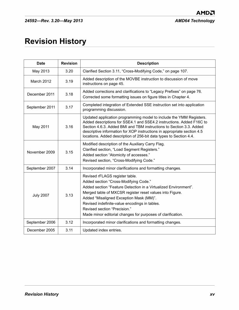
Date Revision Description
May 2013 3.20 Clarified Section 3.11, “Cross-Modifying Code,” on page 107.
March 2012 3.19 Added description of the MOVBE instruction to discussion of move instructions on page 45.
December 2011 3.18Added corrections and clarifications to “Legacy Prefixes” on page 76.Corrected some formatting issues on figure titles in Chapter 4.
September 2011 3.17 Completed integration of Extended SSE instruction set into application programming discussion.
May 2011 3.16
Updated application programming model to include the YMM Registers. Added descriptions for SSE4.1 and SSE4.2 instructions. Added F16C to Section 4.6.3. Added BMI and TBM instructions to Section 3.3. Added descriptive information for XOP instructions in appropriate section 4.5 locations. Added description of 256-bit data types to Section 4.4.
November 2009 3.15
Modified description of the Auxiliary Carry Flag.Clarified section, “Load Segment Registers.”Added section “Atomicity of accesses.”Revised section, “Cross-Modifying Code.”
September 2007 3.14 Incorporated minor clarifications and formatting changes.
July 2007 3.13
Revised rFLAGS register table.Added section “Cross-Modifying Code.”Added section “Feature Detection in a Virtualized Environment”.Merged table of MXCSR register reset values into Figure. Added “Misaligned Exception Mask (MM)”.Revised indefinite-value encodings in tables.Revised section “Precision.”Made minor editorial changes for purposes of clarification.
September 2006 3.12 Incorporated minor clarifications and formatting changes.
December 2005 3.11 Updated index entries.
xvi Revision History
AMD64 Technology 24592—Rev. 3.20—May 2013
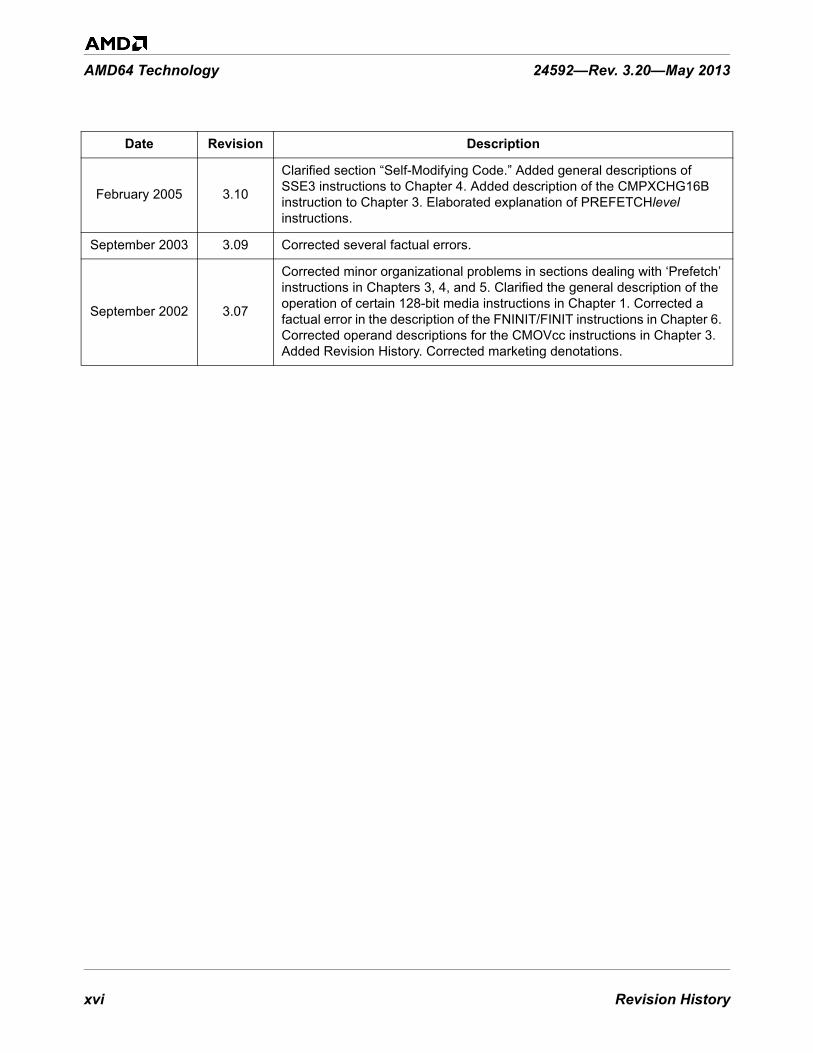
February 2005 3.10
Clarified section “Self-Modifying Code.” Added general descriptions of SSE3 instructions to Chapter 4. Added description of the CMPXCHG16B instruction to Chapter 3. Elaborated explanation of PREFETCHlevel instructions.
September 2003 3.09 Corrected several factual errors.
September 2002 3.07
Corrected minor organizational problems in sections dealing with ‘Prefetch’ instructions in Chapters 3, 4, and 5. Clarified the general description of the operation of certain 128-bit media instructions in Chapter 1. Corrected a factual error in the description of the FNINIT/FINIT instructions in Chapter 6. Corrected operand descriptions for the CMOVcc instructions in Chapter 3. Added Revision History. Corrected marketing denotations.
Date Revision Description

Preface xvii
24592—Rev. 3.20—May 2013 AMD64 Technology
Preface
About This BookThis book is part of a multivolume work entitled the AMD64 Architecture Programmer’s Manual. Thistable lists each volume and its order number.
AudienceThis volume is intended for programmers writing application programs, compilers, or assemblers. Itassumes prior experience in microprocessor programming, although it does not assume priorexperience with the legacy x86 or AMD64 microprocessor architecture.
This volume describes the AMD64 architecture’s resources and functions that are accessible toapplication software, including memory, registers, instructions, operands, I/O facilities, andapplication-software aspects of control transfers (including interrupts and exceptions) andperformance optimization.
System-programming topics—including the use of instructions running at a current privilege level(CPL) of 0 (most-privileged)—are described in Volume 2. Details about each instruction are describedin Volumes 3, 4, and 5.
OrganizationThis volume begins with an overview of the architecture and its memory organization and is followedby chapters that describe the four application-programming models available in the AMD64architecture:
• General-Purpose Programming—This model uses the integer general-purpose registers (GPRs).The chapter describing it also describes the basic application environment for exceptions, controltransfers, I/O, and memory optimization that applies to all other application-programming models.
Title Order No.
Volume 1: Application Programming 24592
Volume 2: System Programming 24593
Volume 3: General-Purpose and System Instructions 24594
Volume 4: 128-Bit and 256-Bit Media Instructions 26568
Volume 5: 64-Bit Media and x87 Floating-Point Instructions 26569

xviii Preface
AMD64 Technology 24592—Rev. 3.20—May 2013
• Streaming SIMD Extensions (SSE) Programming—This model uses the SSE (YMM/XMM)registers and supports integer and floating-point operations on vector (packed) and scalar datatypes.
• Multimedia Extensions (MMX™) Programming—This model uses the 64-bit MMX registers andsupports integer and floating-point operations on vector (packed) and scalar data types.
• x87 Floating-Point Programming—This model uses the 80-bit x87 registers and supports floating-point operations on scalar data types.
The index at the end of this volume cross-references topics within the volume. For other topics relatingto the AMD64 architecture, see the tables of contents and indexes of the other volumes.
Conventions and DefinitionsThe following section Notational Conventions describes notational conventions used in this volumeand in the remaining volumes of this AMD64 Architecture Programmer’s Manual. This is followed bya Definitions section which lists a number of terms used in the manual along with their technicaldefinitions. Some of these definitions assume knowledge of the legacy x86 architecture. See “RelatedDocuments” on page xxix for further information about the legacy x86 architecture. Finally, theRegisters section lists the registers which are a part of the application programming model.
Notational Conventions
#GP(0)An instruction exception—in this example, a general-protection exception with error code of 0.
1011bA binary value—in this example, a 4-bit value.
F0EA_0B02hA hexadecimal value. Underscore characters may be inserted to improve readability.
128Numbers without an alpha suffix are decimal unless the context indicates otherwise.
7:4A bit range, from bit 7 to 4, inclusive. The high-order bit is shown first. Commas may be insertedto indicate gaps.
CR0–CR4A register range, from register CR0 through CR4, inclusive, with the low-order register first.
CR0[PE]Notation for referring to a field within a register—in this case, the PE field of the CR0 register.

Preface xix
24592—Rev. 3.20—May 2013 AMD64 Technology
CR0[PE] = 1The PE field of the CR0 register is set (contains the value 1).
EFER[LME] = 0The LME field of the EFER register is cleared (contains a value of 0).
DS:SIA far pointer or logical address. The real address or segment descriptor specified by the segmentregister (DS in this example) is combined with the offset contained in the second register (SI in thisexample) to form a real or virtual address.
RFLAGS[13:12]A field within a register identified by its bit range. In this example, corresponding to the IOPLfield.
Definitions
128-bit media instructionsInstructions that operate on the various 128-bit vector data types. Supported within both the legacySSE and extended SSE instruction sets.
256-bit media instructionsInstructions that operate on the various 256-bit vector data types. Supported within the extendedSSE instruction set.
64-bit media instructionsInstructions that operate on the 64-bit vector data types. These are primarily a combination ofMMX and 3DNow!™ instruction sets and their extensions, with some additional instructions fromthe SSE1 and SSE2 instruction sets.
16-bit modeLegacy mode or compatibility mode in which a 16-bit address size is active. See legacy mode andcompatibility mode.
32-bit modeLegacy mode or compatibility mode in which a 32-bit address size is active. See legacy mode andcompatibility mode.
64-bit modeA submode of long mode. In 64-bit mode, the default address size is 64 bits and new features, suchas register extensions, are supported for system and application software.
absoluteSaid of a displacement that references the base of a code segment rather than an instruction pointer.Contrast with relative.

xx Preface
AMD64 Technology 24592—Rev. 3.20—May 2013
AESAdvance Encryption Standard (AES) algorithm acceleration instructions; part of Streaming SIMDExtensions (SSE).
ASIDAddress space identifier.
AVXExtension of the SSE instruction set supporting 256-bit vector (packed) operands. See StreamingSIMD Extensions.
biased exponentThe sum of a floating-point value’s exponent and a constant bias for a particular floating-point datatype. The bias makes the range of the biased exponent always positive, which allows reciprocationwithout overflow.
byteEight bits.
clearTo write a bit value of 0. Compare set.
compatibility modeA submode of long mode. In compatibility mode, the default address size is 32 bits, and legacy 16-bit and 32-bit applications run without modification.
commitTo irreversibly write, in program order, an instruction’s result to software-visible storage, such as aregister (including flags), the data cache, an internal write buffer, or memory.
CPLCurrent privilege level.
directReferencing a memory location whose address is included in the instruction’s syntax as animmediate operand. The address may be an absolute or relative address. Compare indirect.
dirty dataData held in the processor’s caches or internal buffers that is more recent than the copy held inmain memory.
displacementA signed value that is added to the base of a segment (absolute addressing) or an instruction pointer(relative addressing). Same as offset.

Preface xxi
24592—Rev. 3.20—May 2013 AMD64 Technology
doublewordTwo words, or four bytes, or 32 bits.
double quadwordEight words, or 16 bytes, or 128 bits. Also called octword.
effective address sizeThe address size for the current instruction after accounting for the default address size and anyaddress-size override prefix.
effective operand sizeThe operand size for the current instruction after accounting for the default operand size and anyoperand-size override prefix.
elementSee vector.
exceptionAn abnormal condition that occurs as the result of executing an instruction. The processor’sresponse to an exception depends on the type of the exception. For all exceptions except SSEfloating-point exceptions and x87 floating-point exceptions, control is transferred to the handler(or service routine) for that exception, as defined by the exception’s vector. For floating-pointexceptions defined by the IEEE 754 standard, there are both masked and unmasked responses.When unmasked, the exception handler is called, and when masked, a default response is providedinstead of calling the handler.
extended SSEEnhanced set of SIMD instructions supporting 256-bit vector data types and allowing thespecification of up to four operands. A subset of the Streaming SIMD Extensions (SSE). Includesthe AVX, FMA, FMA4, and XOP instructions. Compare legacy SSE.
flushAn often ambiguous term meaning (1) writeback, if modified, and invalidate, as in “flush the cacheline,” or (2) invalidate, as in “flush the pipeline,” or (3) change a value, as in “flush to zero.”
FMA4Fused Multiply Add, four operand. Part of the extended SSE instruction set.
FMAFused Multiply Add. Part of the extended SSE instruction set.
GDTGlobal descriptor table.

xxii Preface
AMD64 Technology 24592—Rev. 3.20—May 2013
GIFGlobal interrupt flag.
IDTInterrupt descriptor table.
IGNIgnored. Value written is ignored by hardware. Value returned on a read is indeterminate. Seereserved.
indirectReferencing a memory location whose address is in a register or other memory location. Theaddress may be an absolute or relative address. Compare direct.
IRBThe virtual-8086 mode interrupt-redirection bitmap.
ISTThe long-mode interrupt-stack table.
IVTThe real-address mode interrupt-vector table.
LDTLocal descriptor table.
legacy x86The legacy x86 architecture. See “Related Documents” on page xxix for descriptions of the legacyx86 architecture.
legacy modeAn operating mode of the AMD64 architecture in which existing 16-bit and 32-bit applications andoperating systems run without modification. A processor implementation of the AMD64architecture can run in either long mode or legacy mode. Legacy mode has three submodes, realmode, protected mode, and virtual-8086 mode.
legacy SSEA subset of the Streaming SIMD Extensions (SSE) composed of the SSE1, SSE2, SSE3, SSSE3,SSE4.1, SSE4.2, and SSE4A instruction sets. Compare extended SSE.
long modeAn operating mode unique to the AMD64 architecture. A processor implementation of theAMD64 architecture can run in either long mode or legacy mode. Long mode has two submodes,64-bit mode and compatibility mode.

Preface xxiii
24592—Rev. 3.20—May 2013 AMD64 Technology
lsbLeast-significant bit.
LSBLeast-significant byte.
main memoryPhysical memory, such as RAM and ROM (but not cache memory) that is installed in a particularcomputer system.
mask(1) A control bit that prevents the occurrence of a floating-point exception from invoking anexception-handling routine. (2) A field of bits used for a control purpose.
MBZMust be zero. If software attempts to set an MBZ bit to 1, a general-protection exception (#GP)occurs. See reserved.
memoryUnless otherwise specified, main memory.
msbMost-significant bit.
MSBMost-significant byte.
multimedia instructionsThose instructions that operate simultaneously on multiple elements within a vector data type.Comprises the 256-bit media instructions, 128-bit media instructions, and 64-bit mediainstructions.
octwordSame as double quadword.
offsetSame as displacement.
overflowThe condition in which a floating-point number is larger in magnitude than the largest, finite,positive or negative number that can be represented in the data-type format being used.
packedSee vector.

xxiv Preface
AMD64 Technology 24592—Rev. 3.20—May 2013
PAEPhysical-address extensions.
physical memoryActual memory, consisting of main memory and cache.
probeA check for an address in a processor’s caches or internal buffers. External probes originateoutside the processor, and internal probes originate within the processor.
protected modeA submode of legacy mode.
quadwordFour words, or eight bytes, or 64 bits.
RAZRead as zero. Value returned on a read is always zero (0) regardless of what was previouslywritten. (See reserved)
real-address modeSee real mode.
real modeA short name for real-address mode, a submode of legacy mode.
relativeReferencing with a displacement (also called offset) from an instruction pointer rather than thebase of a code segment. Contrast with absolute.
reservedFields marked as reserved may be used at some future time.To preserve compatibility with future processors, reserved fields require special handling whenread or written by software. Software must not depend on the state of a reserved field (unlessqualified as RAZ), nor upon the ability of such fields to return a previously written state.If a field is marked reserved without qualification, software must not change the state of that field;it must reload that field with the same value returned from a prior read.Reserved fields may be qualified as IGN, MBZ, RAZ, or SBZ (see definitions).
REXAn instruction encoding prefix that specifies a 64-bit operand size and provides access toadditional registers.
RIP-relative addressingAddressing relative to the 64-bit RIP instruction pointer.

Preface xxv
24592—Rev. 3.20—May 2013 AMD64 Technology
SBZShould be zero. An attempt by software to set an SBZ bit to 1 results in undefined behavior. Seereserved.
scalarAn atomic value existing independently of any specification of location, direction, etc., as opposedto vectors.
setTo write a bit value of 1. Compare clear.
SIBA byte following an instruction opcode that specifies address calculation based on scale (S), index(I), and base (B).
SIMDSingle instruction, multiple data. See vector.
Streaming SIMD Extensions (SSE)Instructions that operate on scalar or vector (packed) integer and floating point numbers. The SSEinstruction set comprises the legacy SSE and extended SSE instruction sets.
SSE1Original SSE instruction set. Includes instructions that operate on vector operands in both theMMX and the XMM registers.
SSE2Extensions to the SSE instruction set.
SSE3Further extensions to the SSE instruction set.
SSSE3Further extensions to the SSE instruction set.
SSE4.1Further extensions to the SSE instruction set.
SSE4.2Further extensions to the SSE instruction set.
SSE4AA minor extension to the SSE instruction set adding the instructions EXTRQ, INSERTQ,MOVNTSS, and MOVNTSD.

xxvi Preface
AMD64 Technology 24592—Rev. 3.20—May 2013
sticky bitA bit that is set or cleared by hardware and that remains in that state until explicitly changed bysoftware.
TOPThe x87 top-of-stack pointer.
TSSTask-state segment.
underflowThe condition in which a floating-point number is smaller in magnitude than the smallest nonzero,positive or negative number that can be represented in the data-type format being used.
vector(1) A set of integer or floating-point values, called elements, that are packed into a single operand.Most of the media instructions support vectors as operands. Vectors are also called packed orSIMD (single-instruction multiple-data) operands. (2) An index into an interrupt descriptor table (IDT), used to access exception handlers. Compareexception.
VEXAn instruction encoding escape prefix that opens a new extended instruction encoding space,specifies a 64-bit operand size, and provides access to additional registers. See XOP prefix.
virtual-8086 modeA submode of legacy mode.
VMCBVirtual machine control block.
VMMVirtual machine monitor.
wordTwo bytes, or 16 bits.
XOP instructionsPart of the extended SSE instruction set using the XOP prefix. See Streaming SIMD Extensions.
XOP prefixExtended instruction identifier prefix, used by XOP instructions allowing the specification of up tofour operands and 128 or 256-bit operand widths.

Preface xxvii
24592—Rev. 3.20—May 2013 AMD64 Technology
Registers
In the following list of registers, the names are used to refer either to a given register or to the contentsof that register:
AH–DHThe high 8-bit AH, BH, CH, and DH registers. Compare AL–DL.
AL–DLThe low 8-bit AL, BL, CL, and DL registers. Compare AH–DH.
AL–r15BThe low 8-bit AL, BL, CL, DL, SIL, DIL, BPL, SPL, and R8B–R15B registers, available in 64-bitmode.
BPBase pointer register.
CRnControl register number n.
CSCode segment register.
eAX–eSPThe 16-bit AX, BX, CX, DX, DI, SI, BP, and SP registers or the 32-bit EAX, EBX, ECX, EDX,EDI, ESI, EBP, and ESP registers. Compare rAX–rSP.
EFERExtended features enable register.
eFLAGS16-bit or 32-bit flags register. Compare rFLAGS.
EFLAGS32-bit (extended) flags register.
eIP16-bit or 32-bit instruction-pointer register. Compare rIP.
EIP32-bit (extended) instruction-pointer register.
FLAGS16-bit flags register.

xxviii Preface
AMD64 Technology 24592—Rev. 3.20—May 2013
GDTRGlobal descriptor table register.
GPRsGeneral-purpose registers. For the 16-bit data size, these are AX, BX, CX, DX, DI, SI, BP, and SP.For the 32-bit data size, these are EAX, EBX, ECX, EDX, EDI, ESI, EBP, and ESP. For the 64-bitdata size, these include RAX, RBX, RCX, RDX, RDI, RSI, RBP, RSP, and R8–R15.
IDTRInterrupt descriptor table register.
IP16-bit instruction-pointer register.
LDTRLocal descriptor table register.
MSRModel-specific register.
r8–r15The 8-bit R8B–R15B registers, or the 16-bit R8W–R15W registers, or the 32-bit R8D–R15Dregisters, or the 64-bit R8–R15 registers.
rAX–rSPThe 16-bit AX, BX, CX, DX, DI, SI, BP, and SP registers, or the 32-bit EAX, EBX, ECX, EDX,EDI, ESI, EBP, and ESP registers, or the 64-bit RAX, RBX, RCX, RDX, RDI, RSI, RBP, and RSPregisters. Replace the placeholder r with nothing for 16-bit size, “E” for 32-bit size, or “R” for 64-bit size.
RAX64-bit version of the EAX register.
RBP64-bit version of the EBP register.
RBX64-bit version of the EBX register.
RCX64-bit version of the ECX register.
RDI64-bit version of the EDI register.

Preface xxix
24592—Rev. 3.20—May 2013 AMD64 Technology
RDX64-bit version of the EDX register.
rFLAGS16-bit, 32-bit, or 64-bit flags register. Compare RFLAGS.
RFLAGS64-bit flags register. Compare rFLAGS.
rIP16-bit, 32-bit, or 64-bit instruction-pointer register. Compare RIP.
RIP64-bit instruction-pointer register.
RSI64-bit version of the ESI register.
RSP64-bit version of the ESP register.
SPStack pointer register.
SSStack segment register.
TPRTask priority register (CR8), a new register introduced in the AMD64 architecture to speedinterrupt management.
TRTask register.
Endian Order
The x86 and AMD64 architectures address memory using little-endian byte-ordering. Multibytevalues are stored with their least-significant byte at the lowest byte address, and they are illustratedwith their least significant byte at the right side. Strings are illustrated in reverse order, because theaddresses of their bytes increase from right to left.
Related Documents• Peter Abel, IBM PC Assembly Language and Programming, Prentice-Hall, Englewood Cliffs, NJ,
1995.

xxx Preface
AMD64 Technology 24592—Rev. 3.20—May 2013
• Rakesh Agarwal, 80x86 Architecture & Programming: Volume II, Prentice-Hall, EnglewoodCliffs, NJ, 1991.
• AMD data sheets and application notes for particular hardware implementations of the AMD64architecture.
• AMD, Software Optimization Guide for AMD Family 15h Processors, order number 47414.• AMD, AMD-K6® MMX™ Enhanced Processor Multimedia Technology, Sunnyvale, CA, 2000. • AMD, 3DNow!™ Technology Manual, Sunnyvale, CA, 2000. • AMD, AMD Extensions to the 3DNow!™ and MMX™ Instruction Sets, Sunnyvale, CA, 2000. • Don Anderson and Tom Shanley, Pentium® Processor System Architecture, Addison-Wesley, New
York, 1995. • Nabajyoti Barkakati and Randall Hyde, Microsoft Macro Assembler Bible, Sams, Carmel, Indiana,
1992. • Barry B. Brey, 8086/8088, 80286, 80386, and 80486 Assembly Language Programming,
Macmillan Publishing Co., New York, 1994. • Barry B. Brey, Programming the 80286, 80386, 80486, and Pentium Based Personal Computer,
Prentice-Hall, Englewood Cliffs, NJ, 1995. • Ralf Brown and Jim Kyle, PC Interrupts, Addison-Wesley, New York, 1994. • Penn Brumm and Don Brumm, 80386/80486 Assembly Language Programming, Windcrest
McGraw-Hill, 1993. • Geoff Chappell, DOS Internals, Addison-Wesley, New York, 1994. • Chips and Technologies, Inc. Super386 DX Programmer’s Reference Manual, Chips and
Technologies, Inc., San Jose, 1992. • John Crawford and Patrick Gelsinger, Programming the 80386, Sybex, San Francisco, 1987. • Cyrix Corporation, 5x86 Processor BIOS Writer's Guide, Cyrix Corporation, Richardson, TX,
1995. • Cyrix Corporation, M1 Processor Data Book, Cyrix Corporation, Richardson, TX, 1996. • Cyrix Corporation, MX Processor MMX Extension Opcode Table, Cyrix Corporation, Richardson,
TX, 1996. • Cyrix Corporation, MX Processor Data Book, Cyrix Corporation, Richardson, TX, 1997. • Ray Duncan, Extending DOS: A Programmer's Guide to Protected-Mode DOS, Addison Wesley,
NY, 1991.• William B. Giles, Assembly Language Programming for the Intel 80xxx Family, Macmillan, New
York, 1991. • Frank van Gilluwe, The Undocumented PC, Addison-Wesley, New York, 1994. • John L. Hennessy and David A. Patterson, Computer Architecture, Morgan Kaufmann Publishers,
San Mateo, CA, 1996. • Thom Hogan, The Programmer’s PC Sourcebook, Microsoft Press, Redmond, WA, 1991.

Preface xxxi
24592—Rev. 3.20—May 2013 AMD64 Technology
• Hal Katircioglu, Inside the 486, Pentium®, and Pentium Pro, Peer-to-Peer Communications,Menlo Park, CA, 1997.
• IBM Corporation, 486SLC Microprocessor Data Sheet, IBM Corporation, Essex Junction, VT,1993.
• IBM Corporation, 486SLC2 Microprocessor Data Sheet, IBM Corporation, Essex Junction, VT,1993.
• IBM Corporation, 80486DX2 Processor Floating Point Instructions, IBM Corporation, EssexJunction, VT, 1995.
• IBM Corporation, 80486DX2 Processor BIOS Writer's Guide, IBM Corporation, Essex Junction,VT, 1995.
• IBM Corporation, Blue Lightning 486DX2 Data Book, IBM Corporation, Essex Junction, VT,1994.
• Institute of Electrical and Electronics Engineers, IEEE Standard for Binary Floating-PointArithmetic, ANSI/IEEE Std 754-1985.
• Institute of Electrical and Electronics Engineers, IEEE Standard for Radix-Independent Floating-Point Arithmetic, ANSI/IEEE Std 854-1987.
• Muhammad Ali Mazidi and Janice Gillispie Mazidi, 80X86 IBM PC and Compatible Computers,Prentice-Hall, Englewood Cliffs, NJ, 1997.
• Hans-Peter Messmer, The Indispensable Pentium Book, Addison-Wesley, New York, 1995. • Karen Miller, An Assembly Language Introduction to Computer Architecture: Using the Intel
Pentium®, Oxford University Press, New York, 1999. • Stephen Morse, Eric Isaacson, and Douglas Albert, The 80386/387 Architecture, John Wiley &
Sons, New York, 1987. • NexGen Inc., Nx586 Processor Data Book, NexGen Inc., Milpitas, CA, 1993.• NexGen Inc., Nx686 Processor Data Book, NexGen Inc., Milpitas, CA, 1994.• Bipin Patwardhan, Introduction to the Streaming SIMD Extensions in the Pentium® III,
www.x86.org/articles/sse_pt1/ simd1.htm, June, 2000. • Peter Norton, Peter Aitken, and Richard Wilton, PC Programmer’s Bible, Microsoft® Press,
Redmond, WA, 1993. • PharLap 386|ASM Reference Manual, Pharlap, Cambridge MA, 1993.• PharLap TNT DOS-Extender Reference Manual, Pharlap, Cambridge MA, 1995.• Sen-Cuo Ro and Sheau-Chuen Her, i386/i486 Advanced Programming, Van Nostrand Reinhold,
New York, 1993. • Jeffrey P. Royer, Introduction to Protected Mode Programming, course materials for an onsite
class, 1992. • Tom Shanley, Protected Mode System Architecture, Addison Wesley, NY, 1996. • SGS-Thomson Corporation, 80486DX Processor SMM Programming Manual, SGS-Thomson
Corporation, 1995.

xxxii Preface
AMD64 Technology 24592—Rev. 3.20—May 2013
• Walter A. Triebel, The 80386DX Microprocessor, Prentice-Hall, Englewood Cliffs, NJ, 1992. • John Wharton, The Complete x86, MicroDesign Resources, Sebastopol, California, 1994. • Web sites and newsgroups:
- www.amd.com- news.comp.arch- news.comp.lang.asm.x86- news.intel.microprocessors- news.microsoft

Overview of the AMD64 Architecture 1
24592—Rev. 3.20—May 2013 AMD64 Technology
1 Overview of the AMD64 Architecture
1.1 IntroductionThe AMD64 architecture is a simple yet powerful 64-bit, backward-compatible extension of the industry-standard (legacy) x86 architecture. It adds 64-bit addressing and expands register resources to support higher performance for recompiled 64-bit programs, while supporting legacy 16-bit and 32-bit applications and operating systems without modification or recompilation. It is the architectural basis on which new processors can provide seamless, high-performance support for both the vast body of existing software and 64-bit software required for higher-performance applications.
The need for a 64-bit x86 architecture is driven by applications that address large amounts of virtual and physical memory, such as high-performance servers, database management systems, and CAD tools. These applications benefit from both 64-bit addresses and an increased number of registers. The small number of registers available in the legacy x86 architecture limits performance in computation-intensive applications. Increasing the number of registers provides a performance boost to many such applications.
1.1.1 AMD64 Features
The AMD64 architecture includes these features:
• Register Extensions (see Figure 1-1 on page 2):- 8 additional general-purpose registers (GPRs).- All 16 GPRs are 64 bits wide. - 8 additional YMM/XMM registers. - Uniform byte-register addressing for all GPRs. - An instruction prefix (REX) accesses the extended registers.
• Long Mode (see Table 1-1 on page 2):- Up to 64 bits of virtual address.- 64-bit instruction pointer (RIP).- Instruction-pointer-relative data-addressing mode. - Flat address space.

2 Overview of the AMD64 Architecture
AMD64 Technology 24592—Rev. 3.20—May 2013
Figure 1-1. Application-Programming Register Set
Table 1-1. Operating Modes
Operating Mode Operating System Required
Application Recompile Required
DefaultsRegister
Extensions
Typical Address
Size (bits)
Operand Size (bits)
GPRWidth (bits)
Long Mode
64-Bit Mode
64-bit OSyes 64
32yes 64
CompatibilityMode no
32no
3216 16 16
Legacy Mode
ProtectedMode
Legacy 32-bit OSno
32 32
no
3216 16
Virtual-8086 Mode
16 16 16RealMode Legacy 16-bit OS
513-101 ymm.eps
Flags Register
Instruction Pointer
General-PurposeRegisters (GPRs)
64-Bit Media andFloating-Point Registers
Legacy x86 registers, supported in all modes
63 0 63 0
63 0
79 0
Register extensions, supported in 64-bit mode
RAXRBXRCXRDXRBPRSIRDIRSPR8R9R10R11R12R13R14R15
MMX0/FPR0MMX1/FPR1MMX2/FPR2MMX3/FPR3MMX4/FPR4MMX5/FPR5MMX6/FPR6MMX7/FPR7
0 RFLAGS
RIP
EFLAGS
EIP
SSE MediaRegisters
Application-programming registers not shown includeMedia eXension Control and Status Register (MXCSR) andx87 tag-word, control-word, and status-word registers
255 0
YMM/XMM0YMM/XMM1YMM/XMM2YMM/XMM3YMM/XMM4YMM/XMM5YMM/XMM6YMM/XMM7YMM/XMM8YMM/XMM9YMM/XMM10YMM/XMM11YMM/XMM12YMM/XMM13YMM/XMM14YMM/XMM15
127
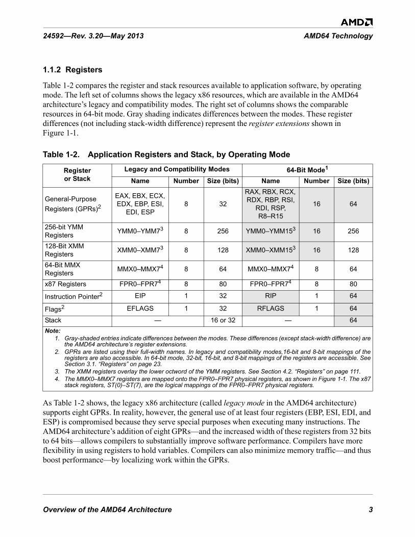
Overview of the AMD64 Architecture 3
24592—Rev. 3.20—May 2013 AMD64 Technology
1.1.2 Registers
Table 1-2 compares the register and stack resources available to application software, by operating mode. The left set of columns shows the legacy x86 resources, which are available in the AMD64 architecture’s legacy and compatibility modes. The right set of columns shows the comparable resources in 64-bit mode. Gray shading indicates differences between the modes. These register differences (not including stack-width difference) represent the register extensions shown in Figure 1-1.
As Table 1-2 shows, the legacy x86 architecture (called legacy mode in the AMD64 architecture) supports eight GPRs. In reality, however, the general use of at least four registers (EBP, ESI, EDI, and ESP) is compromised because they serve special purposes when executing many instructions. The AMD64 architecture’s addition of eight GPRs—and the increased width of these registers from 32 bits to 64 bits—allows compilers to substantially improve software performance. Compilers have more flexibility in using registers to hold variables. Compilers can also minimize memory traffic—and thus boost performance—by localizing work within the GPRs.
Table 1-2. Application Registers and Stack, by Operating Mode
Register or Stack
Legacy and Compatibility Modes 64-Bit Mode1
Name Number Size (bits) Name Number Size (bits)
General-Purpose Registers (GPRs)2
EAX, EBX, ECX, EDX, EBP, ESI,
EDI, ESP8 32
RAX, RBX, RCX, RDX, RBP, RSI,
RDI, RSP, R8–R15
16 64
256-bit YMM Registers YMM0–YMM73 8 256 YMM0–YMM153 16 256
128-Bit XMM Registers XMM0–XMM73 8 128 XMM0–XMM153 16 128
64-Bit MMX Registers MMX0–MMX74 8 64 MMX0–MMX74 8 64
x87 Registers FPR0–FPR74 8 80 FPR0–FPR74 8 80
Instruction Pointer2 EIP 1 32 RIP 1 64
Flags2 EFLAGS 1 32 RFLAGS 1 64
Stack — 16 or 32 — 64Note:
1. Gray-shaded entries indicate differences between the modes. These differences (except stack-width difference) arethe AMD64 architecture’s register extensions.
2. GPRs are listed using their full-width names. In legacy and compatibility modes,16-bit and 8-bit mappings of theregisters are also accessible. In 64-bit mode, 32-bit, 16-bit, and 8-bit mappings of the registers are accessible. SeeSection 3.1. “Registers” on page 23.
3. The XMM registers overlay the lower octword of the YMM registers. See Section 4.2. “Registers” on page 111.4. The MMX0–MMX7 registers are mapped onto the FPR0–FPR7 physical registers, as shown in Figure 1-1. The x87
stack registers, ST(0)–ST(7), are the logical mappings of the FPR0–FPR7 physical registers.

4 Overview of the AMD64 Architecture
AMD64 Technology 24592—Rev. 3.20—May 2013
1.1.3 Instruction Set
The AMD64 architecture supports the full legacy x86 instruction set, with additional instructions to support long mode (see Table 1-1 on page 2 for a summary of operating modes). The application-programming instructions are organized into four subsets, as follows:
• General-Purpose Instructions—These are the basic x86 integer instructions used in virtually all programs. Most of these instructions load, store, or operate on data located in the general-purpose registers (GPRs) or memory. Some of the instructions alter sequential program flow by branching to other program locations.
• Streaming SIMD Extensions Instructions (SSE)—These instructions load, store, or operate on data located primarily in the YMM/XMM registers. 128-bit media instructions operate on the lower half of the YMM registers. SSE instructions perform integer and floating-point operations on vector (packed) and scalar data types. Because the vector instructions can independently and simultaneously perform a single operation on multiple sets of data, they are called single-instruction, multiple-data (SIMD) instructions. They are useful for high-performance media and scientific applications that operate on blocks of data.
• Multimedia Extension Instructions—These include the MMX™ technology and AMD 3DNow!™ technology instructions. These instructions load, store, or operate on data located primarily in the 64-bit MMX registers which are mapped onto the 80-bit x87 floating-point registers. Like the SSE instructions, they perform integer and floating-point operations on vector (packed) and scalar data types. These instructions are useful in media applications that do not require high precision. Multimedia Extension Instructions use saturating mathematical operations that do not generate operation exceptions. AMD has de-emphasized the use of 3DNow! instructions, which have been superceded by their more efficient SSE counterparts. Relevant recommendations are provided in Chapter 5, “64-Bit Media Programming” on page 233, and in the AMD64 Programmer’s Manual Volume 4: 64-Bit Media and x87 Floating-Point Instructions.
• x87 Floating-Point Instructions—These are the floating-point instructions used in legacy x87 applications. They load, store, or operate on data located in the 80-bit x87 registers.
Some of these application-programming instructions bridge two or more of the above subsets. For example, there are instructions that move data between the general-purpose registers and the YMM/XMM or MMX registers, and many of the integer vector (packed) instructions can operate on either YMM/XMM or MMX registers, although not simultaneously. If instructions bridge two or more subsets, their descriptions are repeated in all subsets to which they apply.
1.1.4 Media Instructions
Media applications—such as image processing, music synthesis, speech recognition, full-motion video, and 3D graphics rendering—share certain characteristics:
• They process large amounts of data.• They often perform the same sequence of operations repeatedly across the data.• The data are often represented as small quantities, such as 8 bits for pixel values, 16 bits for audio
samples, and 32 bits for object coordinates in floating-point format.

Overview of the AMD64 Architecture 5
24592—Rev. 3.20—May 2013 AMD64 Technology
SSE and MMX instructions are designed to accelerate these applications. The instructions use a form of vector (or packed) parallel processing known as single-instruction, multiple data (SIMD) processing. This vector technology has the following characteristics:
• A single register can hold multiple independent pieces of data. For example, a single YMM register can hold 32 8-bit integer data elements, or eight 32-bit single-precision floating-point data elements.
• The vector instructions can operate on all data elements in a register, independently and simultaneously. For example, a PADDB instruction operating on byte elements of two vector operands in 128-bit XMM registers performs 16 simultaneous additions and returns 16 independent results in a single operation.
SSE and MMX instructions take SIMD vector technology a step further by including special instructions that perform operations commonly found in media applications. For example, a graphics application that adds the brightness values of two pixels must prevent the add operation from wrapping around to a small value if the result overflows the destination register, because an overflow result can produce unexpected effects such as a dark pixel where a bright one is expected. These instructions include saturating-arithmetic instructions to simplify this type of operation. A result that otherwise would wrap around due to overflow or underflow is instead forced to saturate at the largest or smallest value that can be represented in the destination register.
1.1.5 Floating-Point Instructions
The AMD64 architecture provides three floating-point instruction subsets, using three distinct register sets:
• SSE instructions support 32-bit single-precision and 64-bit double-precision floating-point operations, in addition to integer operations. Operations on both vector data and scalar data are supported, with a dedicated floating-point exception-reporting mechanism. These floating-point operations comply with the IEEE-754 standard.
• MMX Instructions support single-precision floating-point operations. Operations on both vector data and scalar data are supported, but these instructions do not support floating-point exception reporting.
• x87 Floating-Point Instructions support single-precision, double-precision, and 80-bit extended-precision floating-point operations. Only scalar data are supported, with a dedicated floating-point exception-reporting mechanism. The x87 floating-point instructions contain special instructions for performing trigonometric and logarithmic transcendental operations. The single-precision and double-precision floating-point operations comply with the IEEE-754 standard.
Maximum floating-point performance can be achieved using the 256-bit media instructions. One of these vector instructions can support up to eight single-precision (or four double-precision) operations in parallel. A total of 16 256-bit YMM registers, available in 64-bit mode, speeds up applications by providing more registers to hold intermediate results, thus reducing the need to store these results in memory. Fewer loads and stores results in better performance.
6 Overview of the AMD64 Architecture
AMD64 Technology 24592—Rev. 3.20—May 2013
1.2 Modes of OperationTable 1-1 on page 2 summarizes the modes of operation supported by the AMD64 architecture. In most cases, the default address and operand sizes can be overridden with instruction prefixes. The register extensions shown in the second-from-right column of Table 1-1 are those illustrated in Figure 1-1 on page 2.
1.2.1 Long Mode
Long mode is an extension of legacy protected mode. Long mode consists of two submodes: 64-bit mode and compatibility mode. 64-bit mode supports all of the features and register extensions of the AMD64 architecture. Compatibility mode supports binary compatibility with existing 16-bit and 32-bit applications. Long mode does not support legacy real mode or legacy virtual-8086 mode, and it does not support hardware task switching.
Throughout this document, references to long mode refer to both 64-bit mode and compatibility mode. If a function is specific to either of these submodes, then the name of the specific submode is used instead of the name long mode.
1.2.2 64-Bit Mode
64-bit mode—a submode of long mode—supports the full range of 64-bit virtual-addressing and register-extension features. This mode is enabled by the operating system on an individual code-segment basis. Because 64-bit mode supports a 64-bit virtual-address space, it requires a 64-bit operating system and tool chain. Existing application binaries can run without recompilation in compatibility mode, under an operating system that runs in 64-bit mode, or the applications can also be recompiled to run in 64-bit mode.
Addressing features include a 64-bit instruction pointer (RIP) and an RIP-relative data-addressing mode. This mode accommodates modern operating systems by supporting only a flat address space, with single code, data, and stack space.
Register Extensions. 64-bit mode implements register extensions through a group of instruction prefixes, called REX prefixes. These extensions add eight GPRs (R8–R15), widen all GPRs to 64 bits, and add eight YMM/XMM registers (YMM/XMM8–15).
The REX instruction prefixes also provide a byte-register capability that makes the low byte of any of the sixteen GPRs available for byte operations. This results in a uniform set of byte, word, doubleword, and quadword registers that is better suited to compiler register-allocation.
64-Bit Addresses and Operands. In 64-bit mode, the default virtual-address size is 64 bits (implementations can have fewer). The default operand size for most instructions is 32 bits. For most instructions, these defaults can be overridden on an instruction-by-instruction basis using instruction prefixes. REX prefixes specify the 64-bit operand size and register extensions.
RIP-Relative Data Addressing. 64-bit mode supports data addressing relative to the 64-bit instruction pointer (RIP). The legacy x86 architecture supports IP-relative addressing only in control-

Overview of the AMD64 Architecture 7
24592—Rev. 3.20—May 2013 AMD64 Technology
transfer instructions. RIP-relative addressing improves the efficiency of position-independent code and code that addresses global data.
Opcodes. A few instruction opcodes and prefix bytes are redefined to allow register extensions and 64-bit addressing. These differences are described in Appendix B “General-Purpose Instructions in 64-Bit Mode” and Appendix C “Differences Between Long Mode and Legacy Mode” in Volume 3.
1.2.3 Compatibility Mode
Compatibility mode—the second submode of long mode—allows 64-bit operating systems to run existing 16-bit and 32-bit x86 applications. These legacy applications run in compatibility mode without recompilation.
Applications running in compatibility mode use 32-bit or 16-bit addressing and can access the first 4GB of virtual-address space. Legacy x86 instruction prefixes toggle between 16-bit and 32-bit address and operand sizes.
As with 64-bit mode, compatibility mode is enabled by the operating system on an individual code-segment basis. Unlike 64-bit mode, however, x86 segmentation functions the same as in the legacy x86 architecture, using 16-bit or 32-bit protected-mode semantics. From the application viewpoint, compatibility mode looks like the legacy x86 protected-mode environment. From the operating-system viewpoint, however, address translation, interrupt and exception handling, and system data structures use the 64-bit long-mode mechanisms.
1.2.4 Legacy Mode
Legacy mode preserves binary compatibility not only with existing 16-bit and 32-bit applications but also with existing 16-bit and 32-bit operating systems. Legacy mode consists of the following three submodes:
• Protected Mode—Protected mode supports 16-bit and 32-bit programs with memory segmentation, optional paging, and privilege-checking. Programs running in protected mode can access up to 4GB of memory space.
• Virtual-8086 Mode—Virtual-8086 mode supports 16-bit real-mode programs running as tasks under protected mode. It uses a simple form of memory segmentation, optional paging, and limited protection-checking. Programs running in virtual-8086 mode can access up to 1MB of memory space.
• Real Mode—Real mode supports 16-bit programs using simple register-based memory segmentation. It does not support paging or protection-checking. Programs running in real mode can access up to 1MB of memory space.
Legacy mode is compatible with existing 32-bit processor implementations of the x86 architecture. Processors that implement the AMD64 architecture boot in legacy real mode, just like processors that implement the legacy x86 architecture.

8 Overview of the AMD64 Architecture
AMD64 Technology 24592—Rev. 3.20—May 2013
Throughout this document, references to legacy mode refer to all three submodes—protected mode, virtual-8086 mode, and real mode. If a function is specific to either of these submodes, then the name of the specific submode is used instead of the name legacy mode.

Memory Model 9
24592—Rev. 3.20—May 2013 AMD64 Technology
2 Memory Model
This chapter describes the memory characteristics that apply to application software in the various operating modes of the AMD64 architecture. These characteristics apply to all instructions in the architecture. Several additional system-level details about memory and cache management are described in Volume 2.
2.1 Memory Organization
2.1.1 Virtual Memory
Virtual memory consists of the entire address space available to programs. It is a large linear-address space that is translated by a combination of hardware and operating-system software to a smaller physical-address space, parts of which are located in memory and parts on disk or other external storage media.
Figure 2-1 on page 10 shows how the virtual-memory space is treated in the two submodes of long mode:
• 64-bit mode—This mode uses a flat segmentation model of virtual memory. The 64-bit virtual-memory space is treated as a single, flat (unsegmented) address space. Program addresses access locations that can be anywhere in the linear 64-bit address space. The operating system can use separate selectors for code, stack, and data segments for memory-protection purposes, but the base address of all these segments is always 0. (For an exception to this general rule, see “FS and GS as Base of Address Calculation” on page 17.)
• Compatibility mode—This mode uses a protected, multi-segment model of virtual memory, just as in legacy protected mode. The 32-bit virtual-memory space is treated as a segmented set of address spaces for code, stack, and data segments, each with its own base address and protection parameters. A segmented space is specified by adding a segment selector to an address.

10 Memory Model
AMD64 Technology 24592—Rev. 3.20—May 2013
Figure 2-1. Virtual-Memory Segmentation
Operating systems have used segmented memory as a method to isolate programs from the data they used, in an effort to increase the reliability of systems running multiple programs simultaneously. However, most modern operating systems do not use the segmentation features available in the legacy x86 architecture. Instead, these operating systems handle segmentation functions entirely in software. For this reason, the AMD64 architecture dispenses with most of the legacy segmentation functions in 64-bit mode. This allows 64-bit operating systems to be coded more simply, and it supports more efficient management of multi-tasking environments than is possible in the legacy x86 architecture.
2.1.2 Segment Registers
Segment registers hold the selectors used to access memory segments. Figure 2-2 on page 11 shows the application-visible portion of the segment registers. In legacy and compatibility modes, all segment registers are accessible to software. In 64-bit mode, only the CS, FS, and GS segments are recognized by the processor, and software can use the FS and GS segment-base registers as base registers for address calculation, as described in “FS and GS as Base of Address Calculation” on page 17. For references to the DS, ES, or SS segments in 64-bit mode, the processor assumes that the base for each of these segments is zero, neither their segment limit nor attributes are checked, and the processor simply checks that all such addresses are in canonical form, as described in “64-Bit Canonical Addresses” on page 15.
513-107.eps
264 - 1
0
Base Address forAll Segments
Code Segment (CS) Base
Stack Segment (SS) Base
Data Segment (DS) Base
64-Bit Mode(Flat Segmentation Model)
Legacy and Compatibility Mode(Multi-Segment Model)
232 - 1
0
data
code
stack
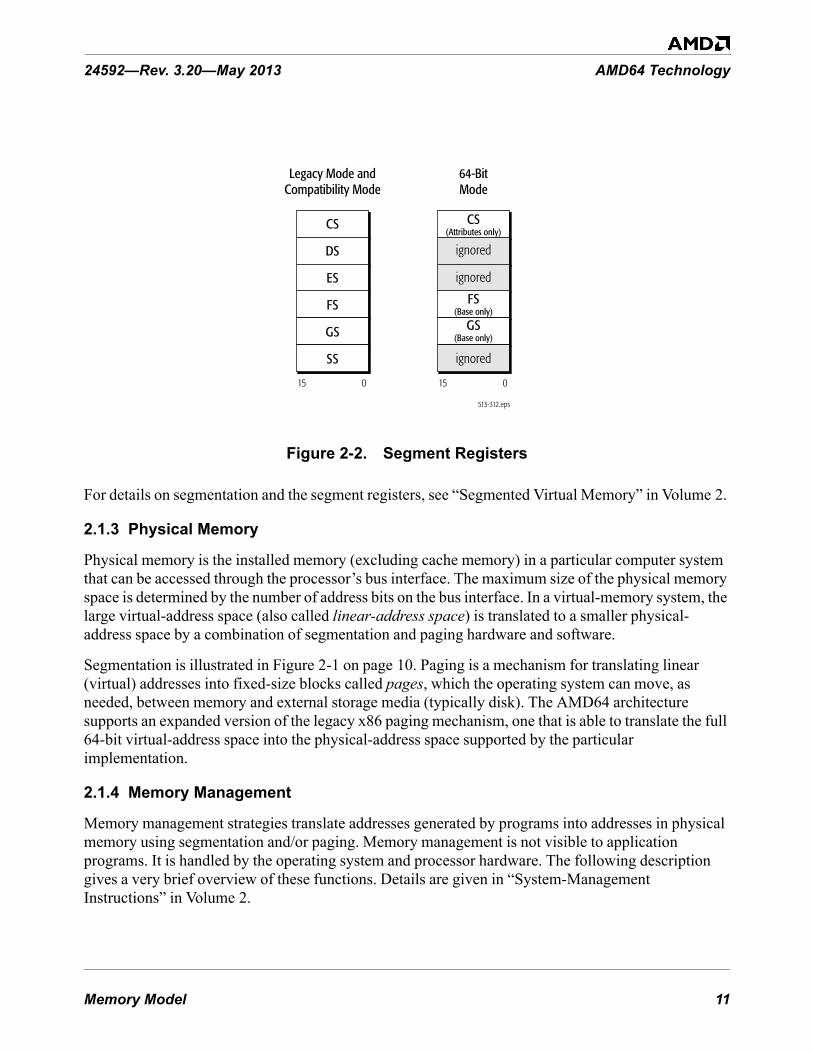
Memory Model 11
24592—Rev. 3.20—May 2013 AMD64 Technology
Figure 2-2. Segment Registers
For details on segmentation and the segment registers, see “Segmented Virtual Memory” in Volume 2.
2.1.3 Physical Memory
Physical memory is the installed memory (excluding cache memory) in a particular computer system that can be accessed through the processor’s bus interface. The maximum size of the physical memory space is determined by the number of address bits on the bus interface. In a virtual-memory system, the large virtual-address space (also called linear-address space) is translated to a smaller physical-address space by a combination of segmentation and paging hardware and software.
Segmentation is illustrated in Figure 2-1 on page 10. Paging is a mechanism for translating linear (virtual) addresses into fixed-size blocks called pages, which the operating system can move, as needed, between memory and external storage media (typically disk). The AMD64 architecture supports an expanded version of the legacy x86 paging mechanism, one that is able to translate the full 64-bit virtual-address space into the physical-address space supported by the particular implementation.
2.1.4 Memory Management
Memory management strategies translate addresses generated by programs into addresses in physical memory using segmentation and/or paging. Memory management is not visible to application programs. It is handled by the operating system and processor hardware. The following description gives a very brief overview of these functions. Details are given in “System-Management Instructions” in Volume 2.
513-312.eps
15 0
ES
FS
GS
SS
CS
DS
15 0
FS(Base only)
GS(Base only)
CS(Attributes only)
Legacy Mode andCompatibility Mode
64-BitMode
ignored
ignored
ignored

12 Memory Model
AMD64 Technology 24592—Rev. 3.20—May 2013
2.1.4.1 Long-Mode Memory Management
Figure 2-3 shows the flow, from top to bottom, of memory management functions performed in the two submodes of long mode.
Figure 2-3. Long-Mode Memory Management
In 64-bit mode, programs generate virtual (linear) addresses that can be up to 64 bits in size. The virtual addresses are passed to the long-mode paging function, which generates physical addresses that can be up to 52 bits in size. (Specific implementations of the architecture can support smaller virtual-address and physical-address sizes.)
In compatibility mode, legacy 16-bit and 32-bit applications run using legacy x86 protected-mode segmentation semantics. The 16-bit or 32-bit effective addresses generated by programs are combined with their segments to produce 32-bit virtual (linear) addresses that are zero-extended to a maximum of 64 bits. The paging that follows is the same long-mode paging function used in 64-bit mode. It translates the virtual addresses into physical addresses. The combination of segment selector and effective address is also called a logical address or far pointer. The virtual address is also called the linear address.
513-184.eps
051
64-Bit Mode
63 0
Paging
051
Compatibility Mode
Segmentation
Paging
031015
Physical Address
Virtual (Linear) Address
Physical Address
Effective AddressSelector
0313263
Virtual Address0

Memory Model 13
24592—Rev. 3.20—May 2013 AMD64 Technology
2.1.4.2 Legacy-Mode Memory Management
Figure 2-4 on page 13 shows the memory-management functions performed in the three submodes of legacy mode.
Figure 2-4. Legacy-Mode Memory Management
The memory-management functions differ, depending on the submode, as follows:
• Protected Mode—Protected mode supports 16-bit and 32-bit programs with table-based memory segmentation, paging, and privilege-checking. The segmentation function takes 32-bit effective addresses and 16-bit segment selectors and produces 32-bit linear addresses into one of 16K memory segments, each of which can be up to 4GB in size. Paging is optional. The 32-bit physical addresses are either produced by the paging function or the linear addresses are used without modification as physical addresses.
• Virtual-8086 Mode—Virtual-8086 mode supports 16-bit programs running as tasks under protected mode. 20-bit linear addresses are formed in the same way as in real mode, but they can optionally be translated through the paging function to form 32-bit physical addresses that access up to 4GB of memory space.
• Real Mode—Real mode supports 16-bit programs using register-based shift-and-add segmentation, but it does not support paging. Sixteen-bit effective addresses are zero-extended and added to a 16-bit segment-base address that is left-shifted four bits, producing a 20-bit linear
513-185.eps
031
Protected Mode
031
Paging
Physical Address (PA)
Linear Address
Virtual-8086 Mode
019
031
Paging
Linear Address
Physical Address (PA)
Real Mode
019
19 031
Linear Address
0 PA
Segmentation
031015
Effective Address (EA)Selector
015
EA
Segmentation
015
Selector
015
EA
Segmentation
015
Selector

14 Memory Model
AMD64 Technology 24592—Rev. 3.20—May 2013
address. The linear address is zero-extended to a 32-bit physical address that can access up to 1MB of memory space.
2.2 Memory Addressing
2.2.1 Byte Ordering
Instructions and data are stored in memory in little-endian byte order. Little-endian ordering places the least-significant byte of the instruction or data item at the lowest memory address and the most-significant byte at the highest memory address.
Figure 2-5 shows a generalization of little-endian memory and register images of a quadword data type. The least-significant byte is at the lowest address in memory and at the right-most byte location of the register image.
Figure 2-5. Byte Ordering
Figure 2-6 on page 15 shows the memory image of a 10-byte instruction. Instructions are byte data types. They are read from memory one byte at a time, starting with the least-significant byte (lowest address). For example, the following instruction specifies the 64-bit instruction MOV RAX, 1122334455667788 instruction that consists of the following ten bytes:
48 B8 8877665544332211
513-116.eps
Quadword in Memory
Quadword in General-Purpose Register
00hbyte 0
01hbyte 1
02hbyte 2
03hbyte 3
04hbyte 4
05hbyte 5
06hbyte 6
07hbyte 7
063
byte 0byte 1byte 2byte 3byte 4byte 5byte 6byte 7
High (most-significant) Low (least-significant)
High (most-significant)
Low (least-significant)

Memory Model 15
24592—Rev. 3.20—May 2013 AMD64 Technology
48 is a REX instruction prefix that specifies a 64-bit operand size, B8 is the opcode that—together with the REX prefix—specifies the 64-bit RAX destination register, and 8877665544332211 is the 8-byte immediate value to be moved, where 88 represents the eighth (least-significant) byte and 11 represents the first (most-significant) byte. In memory, the REX prefix byte (48) would be stored at the lowest address, and the first immediate byte (11) would be stored at the highest instruction address.
Figure 2-6. Example of 10-Byte Instruction in Memory
2.2.2 64-Bit Canonical Addresses
Long mode defines 64 bits of virtual address, but implementations of the AMD64 architecture may support fewer bits of virtual address. Although implementations might not use all 64 bits of the virtual address, they check bits 63 through the most-significant implemented bit to see if those bits are all zeros or all ones. An address that complies with this property is said to be in canonical address form. If a virtual-memory reference is not in canonical form, the implementation causes a general-protection exception or stack fault.
2.2.3 Effective Addresses
Programs provide effective addresses to the hardware prior to segmentation and paging translations. Long-mode effective addresses are a maximum of 64 bits wide, as shown in Figure 2-3 on page 12. Programs running in compatibility mode generate (by default) 32-bit effective addresses, which the hardware zero-extends to 64 bits. Legacy-mode effective addresses, with no address-size override, are 32 or 16 bits wide, as shown in Figure 2-4 on page 13. These sizes can be overridden with an address-size instruction prefix, as described in “Instruction Prefixes” on page 76.
513-186.eps
00h
01h
02h
03h
04h
05h
06h
07h
08h22
09h11 High (most-significant)
Low (least-significant)48
B8
88
77
66
55
44
33

16 Memory Model
AMD64 Technology 24592—Rev. 3.20—May 2013
There are five methods for generating effective addresses, depending on the specific instruction encoding:
• Absolute Addresses—These addresses are given as displacements (or offsets) from the base address of a data segment. They point directly to a memory location in the data segment.
• Instruction-Relative Addresses—These addresses are given as displacements (or offsets) from the current instruction pointer (IP), also called the program counter (PC). They are generated by control-transfer instructions. A displacement in the instruction encoding, or one read from memory, serves as an offset from the address that follows the transfer. See “RIP-Relative Addressing” on page 18 for details about RIP-relative addressing in 64-bit mode.
• Indexed Register-Indirect Addresses—These addresses are calculated off a base address contained in a general-purpose register specified by the instruction (base). Different encodings allow offsets from this base using a signed displacement or using the sum of the displacement and a scaled index value. Instruction encodings may utilize up to ten bytes—the ModRM byte, the optional SIB (scale, index, base) byte and a variable length displacement—to specify the values to be used in the effective address calculation. The base and index values are contained in general-purpose registers specified by the SIB byte. The scale and displacement values are specified directly in the instruction encoding. Figure 2-7 shows the components of the address calculation. The resultant effective address is added to the data-segment base address to form a linear address, as described in “Segmented Virtual Memory” in Volume 2. “Instruction Formats” in Volume 3 gives further details on specifying this form of address.
Figure 2-7. Complex Address Calculation (Protected Mode)
• Stack Addresses—PUSH, POP, CALL, RET, IRET, and INT instructions implicitly use the stack pointer, which contains the address of the procedure stack. See “Stack Operation” on page 19 for details about the size of the stack pointer.
• String Addresses—String instructions generate sequential addresses using the rDI and rSI registers, as described in “Implicit Uses of GPRs” on page 30.
+
513-108.eps
*
Effective Address
DisplacementIndex
Scale by 1, 2, 4, or 8
Base

Memory Model 17
24592—Rev. 3.20—May 2013 AMD64 Technology
In 64-bit mode, with no address-size override, the size of effective-address calculations is 64 bits. An effective-address calculation uses 64-bit base and index registers and sign-extends displacements to 64 bits. Due to the flat address space in 64-bit mode, virtual addresses are equal to effective addresses. (For an exception to this general rule, see “FS and GS as Base of Address Calculation” on page 17.)
2.2.3.1 Long-Mode Zero-Extension of 16-Bit and 32-Bit Addresses
In long mode, all 16-bit and 32-bit address calculations are zero-extended to form 64-bit addresses. Address calculations are first truncated to the effective-address size of the current mode (64-bit mode or compatibility mode), as overridden by any address-size prefix. The result is then zero-extended to the full 64-bit address width.
Because of this, 16-bit and 32-bit applications running in compatibility mode can access only the low 4GB of the long-mode virtual-address space. Likewise, a 32-bit address generated in 64-bit mode can access only the low 4GB of the long-mode virtual-address space.
2.2.3.2 Displacements and Immediates
In general, the maximum size of address displacements and immediate operands is 32 bits. They can be 8, 16, or 32 bits in size, depending on the instruction or, for displacements, the effective address size. In 64-bit mode, displacements are sign-extended to 64 bits during use, but their actual size (for value representation) remains a maximum of 32 bits. The same is true for immediates in 64-bit mode, when the operand size is 64 bits. However, support is provided in 64-bit mode for some 64-bit displacement and immediate forms of the MOV instruction.
2.2.3.3 FS and GS as Base of Address Calculation
In 64-bit mode, the FS and GS segment-base registers (unlike the DS, ES, and SS segment-base registers) can be used as non-zero data-segment base registers for address calculations, as described in “Segmented Virtual Memory” in Volume 2. 64-bit mode assumes all other data-segment registers (DS, ES, and SS) have a base address of 0.
2.2.4 Address-Size Prefix
The default address size of an instruction is determined by the default-size (D) bit and long-mode (L) bit in the current code-segment descriptor (for details, see “Segmented Virtual Memory” in Volume 2). Application software can override the default address size in any operating mode by using the 67h address-size instruction prefix byte. The address-size prefix allows mixing 32-bit and 64-bit addresses on an instruction-by-instruction basis.
Table 2-1 on page 18 shows the effects of using the address-size prefix in all operating modes. In 64-bit mode, the default address size is 64 bits. The address size can be overridden to 32 bits. 16-bit addresses are not supported in 64-bit mode. In compatibility and legacy modes, the address-size prefix works the same as in the legacy x86 architecture.

18 Memory Model
AMD64 Technology 24592—Rev. 3.20—May 2013
2.2.5 RIP-Relative Addressing
RIP-relative addressing—that is, addressing relative to the 64-bit instruction pointer (also called program counter)—is available in 64-bit mode. The effective address is formed by adding the displacement to the 64-bit RIP of the next instruction.
In the legacy x86 architecture, addressing relative to the instruction pointer (IP or EIP) is available only in control-transfer instructions. In the 64-bit mode, any instruction that uses ModRM addressing (see “ModRM and SIB Bytes” in Volume 3) can use RIP-relative addressing. The feature is particularly useful for addressing data in position-independent code and for code that addresses global data.
Programs usually have many references to data, especially global data, that are not register-based. To load such a program, the loader typically selects a location for the program in memory and then adjusts the program’s references to global data based on the load location. RIP-relative addressing of data makes this adjustment unnecessary.
2.2.5.1 Range of RIP-Relative Addressing
Without RIP-relative addressing, instructions encoded with a ModRM byte address memory relative to zero. With RIP-relative addressing, instructions with a ModRM byte can address memory relative to the 64-bit RIP using a signed 32-bit displacement. This provides an offset range of ±2 GBytes from the RIP.
Table 2-1. Address-Size Prefixes
Operating ModeDefault
Address Size (Bits)
Effective Address Size
(Bits)
Address-Size Prefix
(67h)1Required?
Long Mode
64-Bit Mode 6464 no32 yes
Compatibility Mode32
32 no16 yes
1632 yes16 no
Legacy Mode(Protected, Virtual-8086, or Real Mode)
3232 no16 yes
1632 yes16 no
Note:1. “No” indicates that the default address size is used.

Memory Model 19
24592—Rev. 3.20—May 2013 AMD64 Technology
2.2.5.2 Effect of Address-Size Prefix on RIP-Relative Addressing
RIP-relative addressing is enabled by 64-bit mode, not by a 64-bit address-size. Conversely, use of the address-size prefix does not disable RIP-relative addressing. The effect of the address-size prefix is to truncate and zero-extend the computed effective address to 32 bits, like any other addressing mode.
2.2.5.3 Encoding
For details on instruction encoding of RIP-relative addressing, see in “Encoding for RIP-Relative Addressing” in Volume 3.
2.3 PointersPointers are variables that contain addresses rather than data. They are used by instructions to reference memory. Instructions access data using near and far pointers. Stack pointers locate the current stack.
2.3.1 Near and Far Pointers
Near pointers contain only an effective address, which is used as an offset into the current segment. Far pointers contain both an effective address and a segment selector that specifies one of several segments. Figure 2-8 illustrates the two types of pointers.
Figure 2-8. Near and Far Pointers
In 64-bit mode, the AMD64 architecture supports only the flat-memory model in which there is only one data segment, so the effective address is used as the virtual (linear) address and far pointers are not needed. In compatibility mode and legacy protected mode, the AMD64 architecture supports multiple memory segments, so effective addresses can be combined with segment selectors to form far pointers, and the terms logical address (segment selector and effective address) and far pointer are synonyms. Near pointers can also be used in compatibility mode and legacy mode.
2.4 Stack OperationA stack is a portion of a stack segment in memory that is used to link procedures. Software conventions typically define stacks using a stack frame, which consists of two registers—a stack-
513-109.eps
Far PointerNear Pointer
Effective Address (EA) Effective Address (EA)Selector

20 Memory Model
AMD64 Technology 24592—Rev. 3.20—May 2013
frame base pointer (rBP) and a stack pointer (rSP)—as shown in Figure 2-9 on page 20. These stack pointers can be either near pointers or far pointers.
The stack-segment (SS) register, points to the base address of the current stack segment. The stack pointers contain offsets from the base address of the current stack segment. All instructions that address memory using the rBP or rSP registers cause the processor to access the current stack segment.
Figure 2-9. Stack Pointer Mechanism
In typical APIs, the stack-frame base pointer and the stack pointer point to the same location before a procedure call (the top-of-stack of the prior stack frame). After data is pushed onto the stack, the stack-frame base pointer remains where it was and the stack pointer advances downward to the address below the pushed data, where it becomes the new top-of-stack.
In legacy and compatibility modes, the default stack pointer size is 16 bits (SP) or 32 bits (ESP), depending on the default-size (B) bit in the stack-segment descriptor, and multiple stacks can be maintained in separate stack segments. In 64-bit mode, stack pointers are always 64 bits wide (RSP).
Further application-programming details on the stack mechanism are described in “Control Transfers” on page 80. System-programming details on the stack segments are described in “Segmented Virtual Memory” in Volume 2.
2.5 Instruction PointerThe instruction pointer is used in conjunction with the code-segment (CS) register to locate the next instruction in memory. The instruction-pointer register contains the displacement (offset)—from the base address of the current CS segment, or from address 0 in 64-bit mode—to the next instruction to be executed. The pointer is incremented sequentially, except for branch instructions, as described in “Control Transfers” on page 80.
513-110.eps
Stack-Segment (SS) Base Address
Stack-Frame Base Pointer (rBP)and Stack Pointer (rSP)
Stack-Segment (SS) Base Address
Stack-Frame Base Pointer (rBP)Stack Pointer (rSP)
passed data
Stack Frame Before Procedure Call Stack Frame After Procedure Call

Memory Model 21
24592—Rev. 3.20—May 2013 AMD64 Technology
In legacy and compatibility modes, the instruction pointer is a 16-bit (IP) or 32-bit (EIP) register. In 64-bit mode, the instruction pointer is extended to a 64-bit (RIP) register to support 64-bit offsets. The case-sensitive acronym, rIP, is used to refer to any of these three instruction-pointer sizes, depending on the software context.
Figure 2-10 on page 21 shows the relationship between RIP, EIP, and IP. The 64-bit RIP can be used for RIP-relative addressing, as described in “RIP-Relative Addressing” on page 18.
Figure 2-10. Instruction Pointer (rIP) Register
The contents of the rIP are not directly readable by software. However, the rIP is pushed onto the stack by a call instruction.
The memory model described in this chapter is used by all of the programming environments that make up the AMD64 architecture. The next four chapters of this volume describe the application programming environments, which include:
• General-purpose programming (Chapter 3 on page 23). • Streaming SIMD extensions used in media and scientific programming (Chapter 4 on page 109). • 64-bit media programming (Chapter 5 on page 233). • x87 floating-point programming (Chapter 6 on page 279).
513-140.eps
63 31 032
IP
EIP
RIP
rIP

22 Memory Model
AMD64 Technology 24592—Rev. 3.20—May 2013

General-Purpose Programming 23
24592—Rev. 3.20—May 2013 AMD64 Technology
3 General-Purpose Programming
The general-purpose programming model includes the general-purpose registers (GPRs), integer instructions and operands that use the GPRs, program-flow control methods, memory optimization methods, and I/O. This programming model includes the original x86 integer-programming architecture, plus 64-bit extensions and a few additional instructions. Only the application-programming instructions and resources are described in this chapter. Integer instructions typically used in system programming, including all of the privileged instructions, are described in Volume 2, along with other system-programming topics.
The general-purpose programming model is used to some extent by almost all programs, including programs consisting primarily of 256-bit or 128-bit media instructions, 64-bit media instructions, x87 floating-point instructions, or system instructions. For this reason, an understanding of the general-purpose programming model is essential for any programming work using the AMD64 instruction set architecture.
3.1 RegistersFigure 3-1 on page 24 shows an overview of the registers used in general-purpose application programming. They include the general-purpose registers (GPRs), segment registers, flags register, and instruction-pointer register. The number and width of available registers depends on the operating mode.
The registers and register ranges shaded light gray in Figure 3-1 on page 24 are available only in 64-bit mode. Those shaded dark gray are available only in legacy mode and compatibility mode. Thus, in 64-bit mode, the 32-bit general-purpose, flags, and instruction-pointer registers available in legacy mode and compatibility mode are extended to 64-bit widths, eight new GPRs are available, and the DS, ES, and SS segment registers are ignored.
When naming registers, if reference is made to multiple register widths, a lower-case r notation is used. For example, the notation rAX refers to the 16-bit AX, 32-bit EAX, or 64-bit RAX register, depending on an instruction’s effective operand size.

24 General-Purpose Programming
AMD64 Technology 24592—Rev. 3.20—May 2013
Figure 3-1. General-Purpose Programming Registers
3.1.1 Legacy Registers
In legacy and compatibility modes, all of the legacy x86 registers are available. Figure 3-2 on page 25 shows a detailed view of the GPR, flag, and instruction-pointer registers.
513-131.eps
63 31 032
R8
R9
R10
R11
R12
R13
R14
R15
rAX
rBX
rCX
rDX
rBP
rSI
rDI
rSP
63 31 032
rFLAGS
rIP
Available to sofware in all modes
Available to sofware only in 64-bit mode
Ignored by hardware in 64-bit mode
15 0
FS
GS
CS
SegmentRegisters
General-Purpose Registers (GPRs)
Flags and Instruction Pointer Registers
ES
SS
DS

General-Purpose Programming 25
24592—Rev. 3.20—May 2013 AMD64 Technology
Figure 3-2. General Registers in Legacy and Compatibility Modes
The legacy GPRs include:
• Eight 8-bit registers (AH, AL, BH, BL, CH, CL, DH, DL). • Eight 16-bit registers (AX, BX, CX, DX, DI, SI, BP, SP). • Eight 32-bit registers (EAX, EBX, ECX, EDX, EDI, ESI, EBP, ESP).
The size of register used by an instruction depends on the effective operand size or, for certain instructions, the opcode, address size, or stack size. The 16-bit and 32-bit registers are encoded as 0 through 7 in Figure 3-2. For opcodes that specify a byte operand, registers encoded as 0 through 3 refer to the low-byte registers (AL, BL, CL, DL) and registers encoded as 4 through 7 refer to the high-byte registers (AH, BH, CH, DH).
The 16-bit FLAGS register, which is also the low 16 bits of the 32-bit EFLAGS register, shown in Figure 3-2, contains control and status bits accessible to application software, as described in Section 3.1.4, “Flags Register,” on page 34. The 16-bit IP or 32-bit EIP instruction-pointer register contains the address of the next instruction to be executed, as described in Section 2.5, “Instruction Pointer,” on page 20.
513-311.eps
31 15 016
EAX
EBX
ECX
EDX
ESI
EDI
EBP
ESP
AX
16-bitlow8-bit
high8-bit 32-bit
BX
CX
DX
SI
DI
BP
SP
AH (4)
BH (7)
CH (5)
DH (6)
AL
BL
CL
DL
SI
DI
BP
SP
FLAGS
IP
31 0
FLAGS
IP
EFLAGS
EIP
0
3
1
2
6
7
5
4
registerencoding

26 General-Purpose Programming
AMD64 Technology 24592—Rev. 3.20—May 2013
3.1.2 64-Bit-Mode Registers
In 64-bit mode, eight new GPRs are added to the eight legacy GPRs, all 16 GPRs are 64 bits wide, and the low bytes of all registers are accessible. Figure 3-3 on page 27 shows the GPRs, flags register, and instruction-pointer register available in 64-bit mode. The GPRs include:
• Sixteen 8-bit low-byte registers (AL, BL, CL, DL, SIL, DIL, BPL, SPL, R8B, R9B, R10B, R11B, R12B, R13B, R14B, R15B).
• Four 8-bit high-byte registers (AH, BH, CH, DH), addressable only when no REX prefix is used. • Sixteen 16-bit registers (AX, BX, CX, DX, DI, SI, BP, SP, R8W, R9W, R10W, R11W, R12W,
R13W, R14W, R15W). • Sixteen 32-bit registers (EAX, EBX, ECX, EDX, EDI, ESI, EBP, ESP, R8D, R9D, R10D, R11D,
R12D, R13D, R14D, R15D). • Sixteen 64-bit registers (RAX, RBX, RCX, RDX, RDI, RSI, RBP, RSP, R8, R9, R10, R11, R12,
R13, R14, R15).
The size of register used by an instruction depends on the effective operand size or, for certain instructions, the opcode, address size, or stack size. For most instructions, access to the extended GPRs requires a REX prefix (Section 3.5.2, “REX Prefixes,” on page 79). The four high-byte registers (AH, BH, CH, DH) available in legacy mode are not addressable when a REX prefix is used.
In general, byte and word operands are stored in the low 8 or 16 bits of GPRs without modifying their high 56 or 48 bits, respectively. Doubleword operands, however, are normally stored in the low 32 bits of GPRs and zero-extended to 64 bits.
The 64-bit RFLAGS register, shown in Figure 3-3 on page 27, contains the legacy EFLAGS in its low 32-bit range. The high 32 bits are reserved. They can be written with anything but they always read as zero (RAZ). The 64-bit RIP instruction-pointer register contains the address of the next instruction to be executed, as described in Section 3.1.5, “Instruction Pointer Register,” on page 36.

General-Purpose Programming 27
24592—Rev. 3.20—May 2013 AMD64 Technology
Figure 3-3. General Purpose Registers in 64-Bit Mode
Figure 3-4 on page 28 illustrates another way of viewing the 64-bit-mode GPRs, showing how the legacy GPRs overlay the extended GPRs. Gray-shaded bits are not modified in 64-bit mode.
GPRs_64b_mode.eps
R8D
R9D
R10D
R11D
R12D
R13D
R14D
R15D
EAX
EBX
ECX
EDX
ESI
EDI
EBP
ESP
32-bit
R8
R9
R10
R11
R12
R13
R14
R15
RAX
RBX
RCX
RDX
RSI
RDI
RBP
RSP
64-bit
R8W
R9W
R10W
R11W
R12W
R13W
R14W
R15W
AX
16-bit
BX
CX
DX
SI
DI
BP
SP
63 31 15 7 081632
8
9
10
11
12
13
14
15
0
3
1
2
6
7
5
4
zero-extendedfor 32-bit operands
not modified for 8-bit operandsnot modified for 16-bit operands low
8 bits
BPL**
AH*
BH*
CH*
DH*
AL
BL
CL
DL
R8B
R9B
R10B
R11B
R12B
R13B
R14B
R15B
SIL**
DIL**
SPL**
63 31 032
RFLAGS
RIP
0
* Not addressable in REX prefix instruction forms** Only addressable in REX prefix instruction forms
Reg
iste
r En
cod
ing

28 General-Purpose Programming
AMD64 Technology 24592—Rev. 3.20—May 2013
Figure 3-4. GPRs in 64-Bit Mode

General-Purpose Programming 29
24592—Rev. 3.20—May 2013 AMD64 Technology
3.1.2.1 Default Operand Size
For most instructions, the default operand size in 64-bit mode is 32 bits. To access 16-bit operand sizes, an instruction must contain an operand-size prefix (66h), as described in Section 3.2.3, “Operand Sizes and Overrides,” on page 41. To access the full 64-bit operand size, most instructions must contain a REX prefix.
For details on operand size, see Section 3.2.3, “Operand Sizes and Overrides,” on page 41.
3.1.2.2 Byte Registers
64-bit mode provides a uniform set of low-byte, low-word, low-doubleword, and quadword registers that is well-suited for register allocation by compilers. Access to the four new low-byte registers in the legacy-GPR range (SIL, DIL, BPL, SPL), or any of the low-byte registers in the extended registers (R8B–R15B), requires a REX instruction prefix. However, the legacy high-byte registers (AH, BH, CH, DH) are not accessible when a REX prefix is used.
3.1.2.3 Zero-Extension of 32-Bit Results
As Figure 3-3 on page 27 and Figure 3-4 on page 28 show, when performing 32-bit operations with a GPR destination in 64-bit mode, the processor zero-extends the 32-bit result into the full 64-bit destination. 8-bit and 16-bit operations on GPRs preserve all unwritten upper bits of the destination GPR. This is consistent with legacy 16-bit and 32-bit semantics for partial-width results.
Software should explicitly sign-extend the results of 8-bit, 16-bit, and 32-bit operations to the full 64-bit width before using the results in 64-bit address calculations.
The following four code examples show how 64-bit, 32-bit, 16-bit, and 8-bit ADDs work. In these examples, “48” is a REX prefix specifying 64-bit operand size, and “01C3” and “00C3” are the opcode and ModRM bytes of each instruction (see “Opcode Syntax” in Volume 3 for details on the opcode and ModRM encoding).
Example 1: 64-bit Add:Before:RAX =0002_0001_8000_2201
RBX =0002_0002_0123_3301
48 01C3 ADD RBX,RAX ;48 is a REX prefix for size.
Result:RBX = 0004_0003_8123_5502
Example 2: 32-bit Add:Before:RAX = 0002_0001_8000_2201
RBX = 0002_0002_0123_3301
01C3 ADD EBX,EAX ;32-bit add
Result:RBX = 0000_0000_8123_5502 (32-bit result is zero extended)

30 General-Purpose Programming
AMD64 Technology 24592—Rev. 3.20—May 2013
Example 3: 16-bit Add:Before:RAX = 0002_0001_8000_2201
RBX = 0002_0002_0123_3301
66 01C3 ADD BX,AX ;66 is 16-bit size override
Result:RBX = 0002_0002_0123_5502 (bits 63:16 are preserved)
Example 4: 8-bit Add:Before:RAX = 0002_0001_8000_2201
RBX = 0002_0002_0123_3301
00C3 ADD BL,AL ;8-bit add
Result:RBX = 0002_0002_0123_3302 (bits 63:08 are preserved)
3.1.2.4 GPR High 32 Bits Across Mode Switches
The processor does not preserve the upper 32 bits of the 64-bit GPRs across switches from 64-bit mode to compatibility or legacy modes. When using 32-bit operands in compatibility or legacy mode, the high 32 bits of GPRs are undefined. Software must not rely on these undefined bits, because they can change from one implementation to the next or even on a cycle-to-cycle basis within a given implementation. The undefined bits are not a function of the data left by any previously running process.
3.1.3 Implicit Uses of GPRs
Most instructions can use any of the GPRs for operands. However, as Figure 3-1 on page 31 shows, some instructions use some GPRs implicitly. Details about implicit use of GPRs are described in “General-Purpose Instructions in 64-Bit Mode” in Volume 3.
Table 3-1 on page 31 shows implicit register uses only for application instructions. Certain system instructions also make implicit use of registers. These system instructions are described in “System Instruction Reference” in Volume 3.

General-Purpose Programming 31
24592—Rev. 3.20—May 2013 AMD64 Technology
Table 3-1. Implicit Uses of GPRs
Registers1Name Implicit Uses
Low 8-Bit 16-Bit 32-Bit 64-Bit
AL AX EAX RAX2 Accumulator
• Operand for decimal arithmetic, multiply, divide, string, compare-and-exchange, table-translation, and I/O instructions.
• Special accumulator encoding for ADD, XOR, and MOV instructions.
• Used with EDX to hold double-precision operands.
• CPUID processor-feature information.
BL BX EBX RBX2 Base
• Address generation in 16-bit code.
• Memory address for XLAT instruction.
• CPUID processor-feature information.
CL CX ECX RCX2 Count
• Bit index for shift and rotate instructions.
• Iteration count for loop and repeated string instructions.
• Jump conditional if zero.• CPUID processor-feature
information.
DL DX EDX RDX2 I/O Address
• Operand for multiply and divide instructions.
• Port number for I/O instructions.
• Used with EAX to hold double-precision operands.
• CPUID processor-feature information.
SIL2 SI ESI RSI2 Source Index
• Memory address of source operand for string instructions.
• Memory index for 16-bit addresses.
Note:1. Gray-shaded registers have no implicit uses. 2. Accessible only in 64-bit mode.

32 General-Purpose Programming
AMD64 Technology 24592—Rev. 3.20—May 2013
3.1.3.1 Arithmetic Operations
Several forms of the add, subtract, multiply, and divide instructions use AL or rAX implicitly. The multiply and divide instructions also use the concatenation of rDX:rAX for double-sized results (multiplies) or quotient and remainder (divides).
3.1.3.2 Sign-Extensions
The instructions that double the size of operands by sign extension (for example, CBW, CWDE, CDQE, CWD, CDQ, CQO) use rAX register implicitly for the operand. The CWD, CDQ, and CQO instructions also uses the rDX register.
3.1.3.3 Special MOVs
The MOV instruction has several opcodes that implicitly use the AL or rAX register for one operand.
3.1.3.4 String Operations
Many types of string instructions use the accumulators implicitly. Load string, store string, and scan string instructions use AL or rAX for data and rDI or rSI for the offset of a memory address.
3.1.3.5 I/O-Address-Space Operations.
The I/O and string I/O instructions use rAX to hold data that is received from or sent to a device located in the I/O-address space. DX holds the device I/O-address (the port number).
DIL2 DI EDI RDI2 Destination Index
• Memory address of destination operand for string instructions.
• Memory index for 16-bit addresses.
BPL2 BP EBP RBP2 Base Pointer • Memory address of stack-frame base pointer.
SPL2 SP ESP RSP2 Stack Pointer • Memory address of last stack entry (top of stack).
R8B–R10B2 R8W–R10W2 R8D–R10D2 R8–R102 None No implicit uses
R11B2 R11W2 R11D2 R112 None • Holds the value of RFLAGS on SYSCALL/SYSRET.
R12B–R15B2 R12W–R15W2 R12D–R15D2 R12–R152 None No implicit uses
Table 3-1. Implicit Uses of GPRs (continued)
Registers1Name Implicit Uses
Low 8-Bit 16-Bit 32-Bit 64-Bit
Note:1. Gray-shaded registers have no implicit uses. 2. Accessible only in 64-bit mode.

General-Purpose Programming 33
24592—Rev. 3.20—May 2013 AMD64 Technology
3.1.3.6 Table Translations
The table translate instruction (XLATB) uses AL for an memory index and rBX for memory base address.
3.1.3.7 Compares and Exchanges
Compare and exchange instructions (CMPXCHG) use the AL or rAX register for one operand.
3.1.3.8 Decimal Arithmetic
The decimal arithmetic instructions (AAA, AAD, AAM, AAS, DAA, DAS) that adjust binary-coded decimal (BCD) operands implicitly use the AL and AH register for their operations.
3.1.3.9 Shifts and Rotates
Shift and rotate instructions can use the CL register to specify the number of bits an operand is to be shifted or rotated.
3.1.3.10 Conditional Jumps
Special conditional-jump instructions use the rCX register instead of flags. The JCXZ and JrCXZ instructions check the value of the rCX register and pass control to the target instruction when the value of rCX register reaches 0.
3.1.3.11 Repeated String Operations
With the exception of I/O string instructions, all string operations use rSI as the source-operand pointer and rDI as the destination-operand pointer. I/O string instructions use rDX to specify the input-port or output-port number. For repeated string operations (those preceded with a repeat-instruction prefix), the rSI and rDI registers are incremented or decremented as the string elements are moved from the source location to the destination. Repeat-string operations also use rCX to hold the string length, and decrement it as data is moved from one location to the other.
3.1.3.12 Stack Operations
Stack operations make implicit use of the rSP register, and in some cases, the rBP register. The rSP register is used to hold the top-of-stack pointer (or simply, stack pointer). rSP is decremented when items are pushed onto the stack, and incremented when they are popped off the stack. The ENTER and LEAVE instructions use rBP as a stack-frame base pointer. Here, rBP points to the last entry in a data structure that is passed from one block-structured procedure to another.
The use of rSP or rBP as a base register in an address calculation implies the use of SS (stack segment) as the default segment. Using any other GPR as a base register without a segment-override prefix implies the use of the DS data segment as the default segment.
The push all and pop all instructions (PUSHA, PUSHAD, POPA, POPAD) implicitly use all of the GPRs.

34 General-Purpose Programming
AMD64 Technology 24592—Rev. 3.20—May 2013
3.1.3.13 CPUID Information
The CPUID instruction makes implicit use of the EAX, EBX, ECX, and EDX registers. Software loads a function code into EAX and, for some function codes, a sub-function code in ECX, executes the CPUID instruction, and then reads the associated processor-feature information in EAX, EBX, ECX, and EDX.
3.1.4 Flags Register
Figure 3-5 on page 34 shows the 64-bit RFLAGS register and the flag bits visible to application software. Bits 15:0 are the FLAGS register (accessed in legacy real and virtual-8086 modes), bits 31:0 are the EFLAGS register (accessed in legacy protected mode and compatibility mode), and bits 63:0 are the RFLAGS register (accessed in 64-bit mode). The name rFLAGS refers to any of the three register widths, depending on the current software context.
Figure 3-5. rFLAGS Register—Flags Visible to Application Software
The low 16 bits (FLAGS portion) of rFLAGS are accessible by application software and hold the following flags:
• One control flag (the direction flag DF).• Six status flags (carry flag CF, parity flag PF, auxiliary carry flag AF, zero flag ZF, sign flag SF,
and overflow flag OF).
The direction flag (DF) controls the direction of string operations. The status flags provide result information from logical and arithmetic operations and control information for conditional move and jump instructions.
63 32
Reserved, RAZ
31 12 11 10 9 8 7 6 5 4 3 2 1 0
See Volume 2 for System Flags OF
DF
SF
ZF
AF
PF
CF
Bits Mnemonic Description R/W11 OF Overflow Flag R/W10 DF Direction Flag R/W7 SF Sign Flag R/W6 ZF Zero Flag R/W4 AF Auxiliary Carry Flag R/W2 PF Parity Flag R/W0 CF Carry Flag R/W

General-Purpose Programming 35
24592—Rev. 3.20—May 2013 AMD64 Technology
Bits 31:16 of the rFLAGS register contain flags that are accessible only to system software. These flags are described in “System Registers” in Volume 2. The highest 32 bits of RFLAGS are reserved. In 64-bit mode, writes to these bits are ignored. They are read as zeros (RAZ). The rFLAGS register is initialized to 02h on reset, so that all of the programmable bits are cleared to zero.
The effects that rFLAGS bit-values have on instructions are summarized in the following places:
• Conditional Moves (CMOVcc)—Table 3-4 on page 46.• Conditional Jumps (Jcc)—Table 3-5 on page 60.• Conditional Sets (SETcc)—Table 3-6 on page 64.
The effects that instructions have on rFLAGS bit-values are summarized in “Instruction Effects on RFLAGS” in Volume 3.
The sections below describe each application-visible flag. All of these flags are readable and writable. For example, the POPF, POPFD, POPFQ, IRET, IRETD, and IRETQ instructions write all flags. The carry and direction flags are writable by dedicated application instructions. Other application-visible flags are written indirectly by specific instructions. Reserved bits and bits whose writability is prevented by the current values of system flags, current privilege level (CPL), or the current operating mode, are unaffected by the POPFx instructions.
Carry Flag (CF). Bit 0. Hardware sets the carry flag to 1 if the last integer addition or subtraction operation resulted in a carry (for addition) or a borrow (for subtraction) out of the most-significant bit position of the result. Otherwise, hardware clears the flag to 0.
The increment and decrement instructions—unlike the addition and subtraction instructions—do not affect the carry flag. The bit shift and bit rotate instructions shift bits of operands into the carry flag. Logical instructions like AND, OR, XOR clear the carry flag. Bit-test instructions (BTx) set the value of the carry flag depending on the value of the tested bit of the operand.
Software can set or clear the carry flag with the STC and CLC instructions, respectively. Software can complement the flag with the CMC instruction.
Parity Flag (PF). Bit 2. Hardware sets the parity flag to 1 if there is an even number of 1 bits in the least-significant byte of the last result of certain operations. Otherwise (i.e., for an odd number of 1 bits), hardware clears the flag to 0. Software can read the flag to implement parity checking.
Auxiliary Carry Flag (AF). Bit 4. Hardware sets the auxiliary carry flag if an arithmetic operation or a binary-coded decimal (BCD) operation generates a carry (in the case of an addition) or a borrow (in the case of a subtraction) out of bit 3 of the result. Otherwise, AF is cleared to zero.
The main application of this flag is to support decimal arithmetic operations. Most commonly, this flag is used internally by correction commands for decimal addition (AAA) and subtraction (AAS).
Zero Flag (ZF). Bit 6. Hardware sets the zero flag to 1 if the last arithmetic operation resulted in a value of zero. Otherwise (for a non-zero result), hardware clears the flag to 0. The compare and test instructions also affect the zero flag.

36 General-Purpose Programming
AMD64 Technology 24592—Rev. 3.20—May 2013
The zero flag is typically used to test whether the result of an arithmetic or logical operation is zero, or to test whether two operands are equal.
Sign Flag (SF). Bit 7. Hardware sets the sign flag to 1 if the last arithmetic operation resulted in a negative value. Otherwise (for a positive-valued result), hardware clears the flag to 0. Thus, in such operations, the value of the sign flag is set equal to the value of the most-significant bit of the result. Depending on the size of operands, the most-significant bit is bit 7 (for bytes), bit 15 (for words), bit 31 (for doublewords), or bit 63 (for quadwords).
Direction Flag (DF). Bit 10. The direction flag determines the order in which strings are processed. Software can set the direction flag to 1 to specify decrementing the data pointer for the next string instruction (LODSx, STOSx, MOVSx, SCASx, CMPSx, OUTSx, or INSx). Clearing the direction flag to 0 specifies incrementing the data pointer. The pointers are stored in the rSI or rDI register. Software can set or clear the flag with the STD and CLD instructions, respectively.
Overflow Flag (OF). Bit 11. Hardware sets the overflow flag to 1 to indicate that the most-significant (sign) bit of the result of the last signed integer operation differed from the signs of both source operands. Otherwise, hardware clears the flag to 0. A set overflow flag means that the magnitude of the positive or negative result is too big (overflow) or too small (underflow) to fit its defined data type.
The OF flag is undefined after the DIV instruction and after a shift of more than one bit. Logical instructions clear the overflow flag.
3.1.5 Instruction Pointer Register
The instruction pointer register—IP, EIP, or RIP, or simply rIP for any of the three depending on the context—is used in conjunction with the code-segment (CS) register to locate the next instruction in memory. See Section 2.5, “Instruction Pointer,” on page 20 for details.
3.2 OperandsOperands are either referenced by an instruction's encoding or included as an immediate value in the instruction encoding. Depending on the instruction, referenced operands can be located in registers, memory locations, or I/O ports.
3.2.1 Fundamental Data Types
At the most fundamental level, a datum is an ordered string of a specific length composed of binary digits (bits). Bits are indexed from 0 to length-1. While technically the size of a datum is not restricted, for convenience in storing and manipulating data the Architecture defines a finite number of data objects of specific size and names them.
A datum of length 1 is simply a bit. A datum of length 4 is a nibble, a datum of length 8 is a byte, a datum of length 16 is a word, a datum of length 32 is a doubleword, a datum of length 64 is a quadword, a datum of length 128 is a double quadword (also called an octword), a datum of length 256 is a double octword.

General-Purpose Programming 37
24592—Rev. 3.20—May 2013 AMD64 Technology
For instructions that move or reorder data, the significance of each bit within the datum is immaterial. An instruction of this type may operate on bits, bytes, words, doublewords, and so on. The majority of instructions, however, expect operand data to be of a specific format. The format assigns a particular significance to each bit based on its position within the datum. This assignment of significance or meaning to each bit is called data typing.
The Architecture defines the following fundamental data types:
• Untyped data objects- bit- nibble (4 bits) - byte (8 bits)- word (16 bits)- doubleword (32 bits)- quadword (64 bits)- double quadword (octword) (128 bits)- double octword (256 bits)
• Unsigned integers- 8-bit (byte) unsigned integer- 16-bit (word) unsigned integer- 32-bit (doubleword) unsigned integer- 64-bit (quadword) unsigned integer- 128-bit (octword) unsigned integer
• Signed (two's-complement) integers- 8-bit (byte) signed integer- 16-bit (word) signed integer- 32-bit (doubleword) signed integer- 64-bit (quadword) signed integer- 128-bit (octword) signed integer
• Binary coded decimal (BCD) digits• Floating-point data types
- half-precision floating point (16 bits)- single-precision floating point (32 bits)- double-precision floating point (64 bits)
These fundamental data types may be aggregated into composite data types. The defined composite data types are:
• strings

38 General-Purpose Programming
AMD64 Technology 24592—Rev. 3.20—May 2013
- character strings (composed of bytes or words)- doubleword and quadword
• packed BCD• packed signed and unsigned integers (also called integer vectors)• packed single- or double-precision floating point (also called floating-point vectors)
Integer, BCD, and string data types are described in the following section. The floating-point and vector data types are discussed in Section 4.3.3, “SSE Instruction Data Types,” on page 119.
3.2.2 General-Purpose Instruction Data types
The following data types are supported in the general-purpose programming environment:
• Signed (two's-complement) integers.• Unsigned integers.• BCD digits.• Packed BCD digits.• Strings, including bit strings.• Untyped data objects.
Figure 3-6 on page 39 illustrates the data types used by most general-purpose instructions. Software can define data types in ways other than those shown, but the AMD64 architecture does not directly support such interpretations and software must handle them entirely on its own. Note that the bit positions are numbered from right to left starting with 0 and ending with length-1. The untyped data objects bit, nibble, byte, word, doubleword, quadword, and octword are not shown.
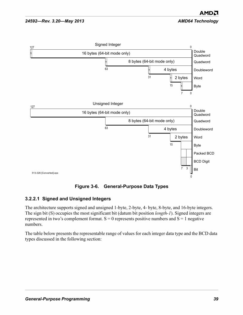
General-Purpose Programming 39
24592—Rev. 3.20—May 2013 AMD64 Technology
Figure 3-6. General-Purpose Data Types
3.2.2.1 Signed and Unsigned Integers
The architecture supports signed and unsigned 1-byte, 2-byte, 4- byte, 8-byte, and 16-byte integers. The sign bit (S) occupies the most significant bit (datum bit position length-1). Signed integers are represented in two’s complement format. S = 0 represents positive numbers and S = 1 negative numbers.
The table below presents the representable range of values for each integer data type and the BCD data types discussed in the following section:
513-326 [Converted].eps
127
63
63
31
15
7 0
Quadword
DoubleQuadword
Doubleword
Word
Byte
0
s
s
s
s
Quadword
Unsigned Integer
Signed Integer
Doubleword
Word
Byte
Bit
8 bytes (64-bit mode only)
16 bytes (64-bit mode only)
127DoubleQuadword
0
16 bytes (64-bit mode only)
4 bytes
2 bytes
31
15
7 3
Packed BCD
BCD Digit
0
8 bytes (64-bit mode only)
4 bytes
2 bytes
S

40 General-Purpose Programming
AMD64 Technology 24592—Rev. 3.20—May 2013
In 64-bit mode, the double quadword (octword) integer data type is supported in the RDX:RAX registers by the MUL, IMUL, DIV, IDIV, and CQO instructions.
3.2.2.2 Binary-Coded-Decimal (BCD) Digits
BCD digits have values ranging from 0 to 9. These values can be represented in binary encoding with four bits. For example, 0000b represents the decimal number 0 and 1001b represents the decimal number 9. Values ranging from 1010b to 1111b are invalid for this data type. Because a byte contains eight bits, two BCD digits can be stored in a single byte. This is referred to as packed-BCD. If a single BCD digit is stored per byte, it is referred to as unpacked-BCD. In the x87 floating-point programming environment (described in Section 6, “x87 Floating-Point Programming,” on page 279) an 80-bit packed BCD data type is also supported, along with conversions between floating-point and BCD data types, so that data expressed in the BCD format can be operated on as floating-point values.
Integer add, subtract, multiply, and divide instructions can be used to operate on single (unpacked) BCD digits. The result must be adjusted to produce a correct BCD representation. For unpacked BCD numbers, the ASCII-adjust instructions are provided to simplify that correction. In the case of division, the adjustment must be made prior to executing the integer-divide instruction.
Similarly, integer add and subtract instructions can be used to operate on packed-BCD digits. The result must be adjusted to produce a correct packed-BCD representation. Decimal-adjust instructions are provided to simplify packed-BCD result corrections.
3.2.2.3 Strings
Strings are a continuous sequence of a single data type. The string instructions can be used to operate on byte, word, doubleword, or quadword data types. The maximum length of a string of any data type is 232–1 bytes, in legacy or compatibility modes, or 264–1 bytes in 64-bit mode. One of the more common types of strings used by applications are byte data-type strings known as ASCII strings, which can be used to represent character data.
Table 3-2. Representable Values of General-Purpose Data Types
Data Type Byte Word Doubleword QuadwordDouble
Quadword2
Signed Integers1 -27 to +(27 -1) -215 to +(215 -1) -231 to +(231 -1) -263 to +(263 -1) -2127 to +(2127 -1)
Unsigned Integers0 to +28-1(0 to 255)
0 to +216-1(0 to 65,535)
0 to +232-1(0 to 4.29 x 10⁹)
0 to +264-1(0 to 1.84 x 10¹⁹)
0 to +2128-1(0 to 3.40 x 1038)
Packed BCD Digits 00 to 99 multiple packed BCD-digit bytes
BCD Digit 0 to 9 multiple BCD-digit bytesNote:
1. The sign bit is the most-significant bit (e.g., bit 7 for a byte, bit 15 for a word, etc.). 2. The double quadword data type is supported in the RDX:RAX registers by the MUL, IMUL, DIV, IDIV, and CQO
instructions.

General-Purpose Programming 41
24592—Rev. 3.20—May 2013 AMD64 Technology
Bit strings are also supported by instructions that operate specifically on bit strings. In general, bit strings can start and end at any bit location within any byte, although the BTx bit-string instructions assume that strings start on a byte boundary. The length of a bit string can range in size from a single bit up to 232–1 bits, in legacy or compatibility modes, or 264–1 bits in 64-bit mode.
3.2.2.4 Untyped Data Objects
Move instructions: register to register, memory to register (load) or register to memory (store); pack, unpack, swap, permutate, and merge instructions operate on data without regard to data type.
SIMD instructions operate on vector data types based on the fundamental data types described above. See Section 4.3. “Operands” on page 116 for a discussion of vector data types
3.2.3 Operand Sizes and Overrides
3.2.3.1 Default Operand Size
In legacy and compatibility modes, the default operand size is either 16 bits or 32 bits, as determined by the default-size (D) bit in the current code-segment descriptor (for details, see “Segmented Virtual Memory” in Volume 2). In 64-bit mode, the default operand size for most instructions is 32 bits.
Application software can override the default operand size by using an operand-size instruction prefix. Table 3-3 shows the instruction prefixes for operand-size overrides in all operating modes. In 64-bit mode, the default operand size for most instructions is 32 bits. A REX prefix (see Section 3.5.2, “REX Prefixes,” on page 79) specifies a 64-bit operand size, and a 66h prefix specifies a 16-bit operand size. The REX prefix takes precedence over the 66h prefix.

42 General-Purpose Programming
AMD64 Technology 24592—Rev. 3.20—May 2013
There are several exceptions to the 32-bit operand-size default in 64-bit mode, including near branches and instructions that implicitly reference the RSP stack pointer. For example, the near CALL, near JMP, Jcc, LOOPcc, POP, and PUSH instructions all default to a 64-bit operand size in 64-bit mode. Such instructions do not need a REX prefix for the 64-bit operand size. For details, see “General-Purpose Instructions in 64-Bit Mode” in Volume 3.
3.2.3.2 Effective Operand Size
The term effective operand size describes the operand size for the current instruction, after accounting for the instruction’s default operand size and any operand-size override or REX prefix that is used with the instruction.
3.2.3.3 Immediate Operand Size
In legacy mode and compatibility modes, the size of immediate operands can be 8, 16, or 32 bits, depending on the instruction. In 64-bit mode, the maximum size of an immediate operand is also 32 bits, except that 64-bit immediates can be copied into a 64-bit GPR using the MOV instruction.
When the operand size of a MOV instruction is 64 bits, the processor sign-extends immediates to 64 bits before using them. Support for true 64-bit immediates is accomplished by expanding the semantics of the MOV reg, imm16/32 instructions. In legacy and compatibility modes, these instructions—opcodes B8h through BFh—copy a 16-bit or 32-bit immediate (depending on the
Table 3-3. Operand-Size Overrides
Operating ModeDefault
Operand Size (Bits)
EffectiveOperand
Size (Bits)
Instruction Prefix
66h1 REX
Long Mode
64-BitMode 322
64 x yes32 no no16 yes no
CompatibilityMode
3232 no
Not Applicable
16 yes
1632 yes16 no
Legacy Mode(Protected, Virtual-8086, or Real Mode)
3232 no16 yes
1632 yes16 no
Note:1. A “no” indicates that the default operand size is used. An “x” means “don’t care.”2. Near branches, instructions that implicitly reference the stack pointer, and certain
other instructions default to 64-bit operand size. See “General-Purpose Instructionsin 64-Bit Mode” in Volume 3

General-Purpose Programming 43
24592—Rev. 3.20—May 2013 AMD64 Technology
effective operand size) into a GPR. In 64-bit mode, if the operand size is 64 bits (requires a REX prefix), these instructions can be used to copy a true 64-bit immediate into a GPR.
3.2.4 Operand Addressing
Operands for general-purpose instructions are referenced by the instruction's syntax or they are incorporated in the instruction as an immediate value. Referenced operands can be in registers, memory, or I/O ports.
3.2.4.1 Register Operands
Most general-purpose instructions that take register operands reference the general-purpose registers (GPRs). A few general-purpose instructions reference operands in the RFLAGS register, XMM registers, or MMX™ registers.
The type of register addressed is specified in the instruction syntax. When addressing GPRs or XMM registers, the REX instruction prefix can be used to access the extended GPRs or XMM registers, as described in Section 3.5, “Instruction Prefixes,” on page 76.
3.2.4.2 Memory Operands
Many general-purpose instructions can access operands in memory. Section 2.2, “Memory Addressing,” on page 14 describes the general methods and conditions for addressing memory operands.
3.2.4.3 I/O Ports
Operands in I/O ports are referenced according to the conventions described in Section 3.8, “Input/Output,” on page 94.
3.2.4.4 Immediate Operands
In certain instructions, a source operand—called an immediate operand, or simply immediate—is included as part of the instruction rather than being accessed from a register or memory location. For details on the size of immediate operands, see “Immediate Operand Size” on page 42.
3.2.5 Data Alignment
A data access is aligned if its address is a multiple of its operand size, in bytes. The following examples illustrate this definition:
• Byte accesses are always aligned. Bytes are the smallest addressable parts of memory. • Word (two-byte) accesses are aligned if their address is a multiple of 2.• Doubleword (four-byte) accesses are aligned if their address is a multiple of 4.• Quadword (eight-byte) accesses are aligned if their address is a multiple of 8.
The AMD64 architecture does not impose data-alignment requirements for accessing data in memory. However, depending on the location of the misaligned operand with respect to the width of the data

44 General-Purpose Programming
AMD64 Technology 24592—Rev. 3.20—May 2013
bus and other aspects of the hardware implementation (such as store-to-load forwarding mechanisms), a misaligned memory access can require more bus cycles than an aligned access. For maximum performance, avoid misaligned memory accesses.
Performance on many hardware implementations will benefit from observing the following operand-alignment and operand-size conventions:
• Avoid misaligned data accesses.• Maintain consistent use of operand size across all loads and stores. Larger operand sizes
(doubleword and quadword) tend to make more efficient use of the data bus and any data-forwarding features that are implemented by the hardware.
• When using word or byte stores, avoid loading data from the same doubleword of memory, other than the identical start addresses of the stores.
3.3 Instruction SummaryThis section summarizes the functions of the general-purpose instructions. The instructions are organized by functional group—such as, data-transfer instructions, arithmetic instructions, and so on. Details on individual instructions are given in the alphabetically organized “General-Purpose Instructions in 64-Bit Mode” in Volume 3.
3.3.1 Syntax
Each instruction has a mnemonic syntax used by assemblers to specify the operation and the operands to be used for source and destination (result) data. Figure 3-7 shows an example of the mnemonic syntax for a compare (CMP) instruction. In this example, the CMP mnemonic is followed by two operands, a 32-bit register or memory operand and an 8-bit immediate operand.
Figure 3-7. Mnemonic Syntax Example
In most instructions that take two operands, the first (left-most) operand is both a source operand and the destination operand. The second (right-most) operand serves only as a source. Instructions can have one or more prefixes that modify default instruction functions or operand properties. These
513-139.eps
Mnemonic
First Source Operandand Destination Operand
Second Source Operand
CMP reg/mem32, imm8

General-Purpose Programming 45
24592—Rev. 3.20—May 2013 AMD64 Technology
prefixes are summarized in Section 3.5, “Instruction Prefixes,” on page 76. Instructions that access 64-bit operands in a general-purpose register (GPR) or any of the extended GPR or XMM registers require a REX instruction prefix.
Unless otherwise stated in this section, the word register means a general-purpose register (GPR). Several instructions affect the flag bits in the RFLAGS register. “Instruction Effects on RFLAGS” in Volume 3 summarizes the effects that instructions have on rFLAGS bits.
3.3.2 Data Transfer
The data-transfer instructions copy data between registers and memory.
Move• MOV—Move• MOVBE—Move Big-Endian • MOVSX—Move with Sign-Extend• MOVZX—Move with Zero-Extend• MOVD—Move Doubleword or Quadword• MOVNTI—Move Non-temporal Doubleword or Quadword
The move instructions copy a byte, word, doubleword, or quadword from a register or memory location to a register or memory location. The source and destination cannot both be memory locations. For MOVBE, both operands cannot be registers and the operand size must be greater than one byte. MOVBE performs a reordering of the bytes within the source operand as it is copied.
An immediate constant can be used as a source operand with the MOV instruction. For most move instructions, the destination must be of the same size as the source, but the MOVSX and MOVZX instructions copy values of smaller size to a larger size by using sign-extension or zero-extension respectively. The MOVD instruction copies a doubleword or quadword between a general-purpose register or memory and an XMM or MMX register.
The MOV instruction is in many aspects similar to the assignment operator in high-level languages. The simplest example of their use is to initialize variables. To initialize a register to 0, rather than using a MOV instruction it may be more efficient to use the XOR instruction with identical destination and source operands.
The MOVNTI instruction stores a doubleword or quadword from a register into memory as “non-temporal” data, which assumes a single access (as opposed to frequent subsequent accesses of “temporal data”). The operation therefore minimizes cache pollution. The exact method by which cache pollution is minimized depends on the hardware implementation of the instruction. For further information, see Section 3.9, “Memory Optimization,” on page 97.
Conditional Move• CMOVcc—Conditional Move If condition

46 General-Purpose Programming
AMD64 Technology 24592—Rev. 3.20—May 2013
The CMOVcc instructions conditionally copy a word, doubleword, or quadword from a register or memory location to a register location. The source and destination must be of the same size.
The CMOVcc instructions perform the same task as MOV but work conditionally, depending on the state of status flags in the RFLAGS register. If the condition is not satisfied, the instruction has no effect and control is passed to the next instruction. The mnemonics of CMOVcc instructions indicate the condition that must be satisfied. Several mnemonics are often used for one opcode to make the mnemonics easier to remember. For example, CMOVE (conditional move if equal) and CMOVZ (conditional move if zero) are aliases and compile to the same opcode. Table 3-4 shows the RFLAGS values required for each CMOVcc instruction.
In assembly languages, the conditional move instructions correspond to small conditional statements like:
IF a = b THEN x = y
CMOVcc instructions can replace two instructions—a conditional jump and a move. For example, to perform a high-level statement like:
IF ECX = 5 THEN EAX = EBX
without a CMOVcc instruction, the code would look like:cmp ecx, 5 ; test if ecx equals 5jnz Continue ; test condition and skip if not metmov eax, ebx ; moveContinue: ; continuation
but with a CMOVcc instruction, the code would look like:cmp ecx, 5 ; test if ecx equals to 5cmovz eax, ebx ; test condition and move
Replacing conditional jumps with conditional moves also has the advantage that it can avoid branch-prediction penalties that may be caused by conditional jumps.
Support for CMOVcc instructions depends on the processor implementation. To find out if a processor is able to perform CMOVcc instructions, use the CPUID instruction. For more information on using the CPUID instruction, see Section 3.6, “Feature Detection,” on page 79.
Table 3-4. rFLAGS for CMOVcc InstructionsMnemonic Required Flag State Description
CMOVO OF = 1 Conditional move if overflowCMOVNO OF = 0 Conditional move if not overflowCMOVBCMOVCCMOVNAE
CF = 1Conditional move if belowConditional move if carryConditional move if not above or equal

General-Purpose Programming 47
24592—Rev. 3.20—May 2013 AMD64 Technology
Stack Operations• POP—Pop Stack• POPA—Pop All to GPR Words• POPAD—Pop All to GPR Doublewords• PUSH—Push onto Stack• PUSHA—Push All GPR Words onto Stack• PUSHAD—Push All GPR Doublewords onto Stack• ENTER—Create Procedure Stack Frame• LEAVE—Delete Procedure Stack Frame
PUSH copies the specified register, memory location, or immediate value to the top of stack. This instruction decrements the stack pointer by 2, 4, or 8, depending on the operand size, and then copies the operand into the memory location pointed to by SS:rSP.
CMOVAECMOVNBCMOVNC
CF = 0Conditional move if above or equalConditional move if not belowConditional move if not carry
CMOVECMOVZ ZF = 1 Conditional move if equal
Conditional move if zeroCMOVNECMOVNZ ZF = 0 Conditional move if not equal
Conditional move if not zeroCMOVBECMOVNA CF = 1 or ZF = 1 Conditional move if below or equal
Conditional move if not aboveCMOVACMOVNBE CF = 0 and ZF = 0 Conditional move if not below or equal
Conditional move if not below or equalCMOVS SF = 1 Conditional move if signCMOVNS SF = 0 Conditional move if not signCMOVPCMOVPE PF = 1 Conditional move if parity
Conditional move if parity evenCMOVNPCMOVPO PF = 0 Conditional move if not parity
Conditional move if parity oddCMOVLCMOVNGE SF <> OF Conditional move if less
Conditional move if not greater or equalCMOVGECMOVNL SF = OF Conditional move if greater or equal
Conditional move if not lessCMOVLECMOVNG ZF = 1 or SF <> OF Conditional move if less or equal
Conditional move if not greaterCMOVGCMOVNLE ZF = 0 and SF = OF Conditional move if greater
Conditional move if not less or equal
Table 3-4. rFLAGS for CMOVcc Instructions (continued)Mnemonic Required Flag State Description

48 General-Purpose Programming
AMD64 Technology 24592—Rev. 3.20—May 2013
POP copies a word, doubleword, or quadword from the memory location pointed to by the SS:rSP registers (the top of stack) to a specified register or memory location. Then, the rSP register is incremented by 2, 4, or 8. After the POP operation, rSP points to the new top of stack.
PUSHA or PUSHAD stores eight word-sized or doubleword-sized registers onto the stack: eAX, eCX, eDX, eBX, eSP, eBP, eSI and eDI, in that order. The stored value of eSP is sampled at the moment when the PUSHA instruction started. The resulting stack-pointer value is decremented by 16 or 32.
POPA or POPAD extracts eight word-sized or doubleword-sized registers from the stack: eDI, eSI, eBP, eSP, eBX, eDX, eCX and eAX, in that order (which is the reverse of the order used in the PUSHA instruction). The stored eSP value is ignored by the POPA instruction. The resulting stack pointer value is incremented by 16 or 32.
It is a common practice to use PUSH instructions to pass parameters (via the stack) to functions and subroutines. The typical instruction sequence used at the beginning of a subroutine looks like:
push ebp ; save current EBPmov ebp, esp ; set stack frame pointer valuesub esp, N ; allocate space for local variables
The rBP register is used as a stack frame pointer—a base address of the stack area used for parameters passed to subroutines and local variables. Positive offsets of the stack frame pointed to by rBP provide access to parameters passed while negative offsets give access to local variables. This technique allows creating re-entrant subroutines.
The ENTER and LEAVE instructions provide support for procedure calls, and are mainly used in high-level languages. The ENTER instruction is typically the first instruction of the procedure, and the LEAVE instruction is the last before the RET instruction.
The ENTER instruction creates a stack frame for a procedure. The first operand, size, specifies the number of bytes allocated in the stack. The second operand, depth, specifies the number of stack-frame pointers copied from the calling procedure’s stack (i.e., the nesting level). The depth should be an integer in the range 0–31.
Typically, when a procedure is called, the stack contains the following four components:
• Parameters passed to the called procedure (created by the calling procedure). • Return address (created by the CALL instruction). • Array of stack-frame pointers (pointers to stack frames of procedures with smaller nesting-level
depth) which are used to access the local variables of such procedures. • Local variables used by the called procedure.
All these data are called the stack frame. The ENTER instruction simplifies management of the last two components of a stack frame. First, the current value of the rBP register is pushed onto the stack. The value of the rSP register at that moment is a frame pointer for the current procedure: positive offsets from this pointer give access to the parameters passed to the procedure, and negative offsets give access to the local variables which will be allocated later. During procedure execution, the value of the frame pointer is stored in the rBP register, which at that moment contains a frame pointer of the

General-Purpose Programming 49
24592—Rev. 3.20—May 2013 AMD64 Technology
calling procedure. This frame pointer is saved in a temporary register. If the depth operand is greater than one, the array of depth-1 frame pointers of procedures with smaller nesting level is pushed onto the stack. This array is copied from the stack frame of the calling procedure, and it is addressed by the rBP register from the calling procedure. If the depth operand is greater than zero, the saved frame pointer of the current procedure is pushed onto the stack (forming an array of depth frame pointers). Finally, the saved value of the frame pointer is copied to the rBP register, and the rSP register is decremented by the value of the first operand, allocating space for local variables used in the procedure. See “Stack Operations” on page 47 for a parameter-passing instruction sequence using PUSH that is equivalent to ENTER.
The LEAVE instruction removes local variables and the array of frame pointers, allocated by the previous ENTER instruction, from the stack frame. This is accomplished by the following two steps: first, the value of the frame pointer is copied from the rBP register to the rSP register. This releases the space allocated by local variables and an array of frame pointers of procedures with smaller nesting levels. Second, the rBP register is popped from the stack, restoring the previous value of the frame pointer (or simply the value of the rBP register, if the depth operand is zero). Thus, the LEAVE instruction is equivalent to the following code:
mov rSP, rBPpop rBP
3.3.3 Data Conversion
The data-conversion instructions perform various transformations of data, such as operand-size doubling by sign extension, conversion of little-endian to big-endian format, extraction of sign masks, searching a table, and support for operations with decimal numbers.
Sign Extension• CBW—Convert Byte to Word• CWDE—Convert Word to Doubleword• CDQE—Convert Doubleword to Quadword• CWD—Convert Word to Doubleword• CDQ—Convert Doubleword to Quadword• CQO—Convert Quadword to Octword
The CBW, CWDE, and CDQE instructions sign-extend the AL, AX, or EAX register to the upper half of the AX, EAX, or RAX register, respectively. By doing so, these instructions create a double-sized destination operand in rAX that has the same numerical value as the source operand. The CBW, CWDE, and CDQE instructions have the same opcode, and the action taken depends on the effective operand size.
The CWD, CDQ and CQO instructions sign-extend the AX, EAX, or RAX register to all bit positions of the DX, EDX, or RDX register, respectively. By doing so, these instructions create a double-sized destination operand in rDX:rAX that has the same numerical value as the source operand. The CWD,

50 General-Purpose Programming
AMD64 Technology 24592—Rev. 3.20—May 2013
CDQ, and CQO instructions have the same opcode, and the action taken depends on the effective operand size.
Flags are not affected by these instructions. The instructions can be used to prepare an operand for signed division (performed by the IDIV instruction) by doubling its storage size.
Extract Sign Mask• (V)MOVMSKPS—Extract Packed Single-Precision Floating-Point Sign Mask• (V)MOVMSKPD—Extract Packed Double-Precision Floating-Point Sign Mask
The MOVMSKPS instruction moves the sign bits of four packed single-precision floating-point values in an XMM register to the four low-order bits of a general-purpose register, with zero-extension. MOVMSKPD does a similar operation for two packed double-precision floating-point values: it moves the two sign bits to the two low-order bits of a general-purpose register, with zero-extension. The result of either instruction is a sign-bit mask.
Translate• XLAT—Translate Table Index
The XLAT instruction replaces the value stored in the AL register with a table element. The initial value in AL serves as an unsigned index into the table, and the start (base) of table is specified by the DS:rBX registers (depending on the effective address size).
This instruction is not recommended. The following instruction serves to replace it:MOV AL,[rBX + AL]
ASCII Adjust• AAA—ASCII Adjust After Addition• AAD—ASCII Adjust Before Division• AAM—ASCII Adjust After Multiply• AAS—ASCII Adjust After Subtraction
The AAA, AAD, AAM, and AAS instructions perform corrections of arithmetic operations with non-packed BCD values (i.e., when the decimal digit is stored in a byte register). There are no instructions which directly operate on decimal numbers (either packed or non-packed BCD). However, the ASCII-adjust instructions correct decimal-arithmetic results. These instructions assume that an arithmetic instruction, such as ADD, was performed on two BCD operands, and that the result was stored in the AL or AX register. This result can be incorrect or it can be a non-BCD value (for example, when a decimal carry occurs). After executing the proper ASCII-adjust instruction, the AX register contains a correct BCD representation of the result. (The AAD instruction is an exception to this, because it should be applied before a DIV instruction, as explained below). All of the ASCII-adjust instructions are able to operate with multiple-precision decimal values.
AAA should be applied after addition of two non-packed decimal digits. AAS should be applied after subtraction of two non-packed decimal digits. AAM should be applied after multiplication of two non-

General-Purpose Programming 51
24592—Rev. 3.20—May 2013 AMD64 Technology
packed decimal digits. AAD should be applied before the division of two non-packed decimal numbers.
Although the base of the numeration for ASCII-adjust instructions is assumed to be 10, the AAM and AAD instructions can be used to correct multiplication and division with other bases.
BCD Adjust• DAA—Decimal Adjust after Addition• DAS—Decimal Adjust after Subtraction
The DAA and DAS instructions perform corrections of addition and subtraction operations on packed BCD values. (Packed BCD values have two decimal digits stored in a byte register, with the higher digit in the higher four bits, and the lower one in the lower four bits.) There are no instructions for correction of multiplication and division with packed BCD values.
DAA should be applied after addition of two packed-BCD numbers. DAS should be applied after subtraction of two packed-BCD numbers.
DAA and DAS can be used in a loop to perform addition or subtraction of two multiple-precision decimal numbers stored in packed-BCD format. Each loop cycle would operate on corresponding bytes (containing two decimal digits) of operands.
Endian Conversion• BSWAP—Byte Swap
The BSWAP instruction changes the byte order of a doubleword or quadword operand in a register, as shown in Figure 3-8. In a doubleword, bits 7:0 are exchanged with bits 31:24, and bits 15:8 are exchanged with bits 23:16. In a quadword, bits 7:0 are exchanged with bits 63:56, bits 15:8 with bits 55:48, bits 23:16 with bits 47:40, and bits 31:24 with bits 39:32. See the following illustration.
Figure 3-8. BSWAP Doubleword Exchange
A second application of the BSWAP instruction to the same operand restores its original value. The result of applying the BSWAP instruction to a 16-bit register is undefined. To swap bytes of a 16-bit register, use the XCHG instruction.
The BSWAP instruction is used to convert data between little-endian and big-endian byte order.
07815162331 24
07815162331 24

52 General-Purpose Programming
AMD64 Technology 24592—Rev. 3.20—May 2013
3.3.4 Load Segment Registers
These instructions load segment registers.
• LDS, LES, LFS, LGS, LSS—Load Far Pointer• MOV segReg—Move Segment Register• POP segReg—Pop Stack Into Segment Register
The LDS, LES, LFD, LGS, and LSS instructions atomically (with respect to interrupts only, not contending memory accesses) load the two parts of a far pointer into a segment register and a general-purpose register. A far pointer is a 16-bit segment selector and a 16-bit or 32-bit offset. The load copies the segment-selector portion of the pointer from memory into the segment register and the offset portion of the pointer from memory into a general-purpose register.
The effective operand size determines the size of the offset loaded by the LDS, LES, LFD, LGS, and LSS instructions. The instructions load not only the software-visible segment selector into the segment register, but they also cause the hardware to load the associated segment-descriptor information into the software-invisible (hidden) portion of that segment register.
The MOV segReg and POP segReg instructions load a segment selector from a general-purpose register or memory (for MOV segReg) or from the top of the stack (for POP segReg) to a segment register. These instructions not only load the software-visible segment selector into the segment register but also cause the hardware to load the associated segment-descriptor information into the software-invisible (hidden) portion of that segment register.
In 64-bit mode, the POP DS, POP ES, and POP SS instructions are invalid.
3.3.5 Load Effective Address• LEA—Load Effective Address
The LEA instruction calculates and loads the effective address (offset within a given segment) of a source operand and places it in a general-purpose register.
LEA is related to MOV, which copies data from a memory location to a register, but LEA takes the address of the source operand, whereas MOV takes the contents of the memory location specified by the source operand. In the simplest cases, LEA can be replaced with MOV. For example:
lea eax, [ebx]
has the same effect as:mov eax, ebx
However, LEA allows software to use any valid addressing mode for the source operand. For example:lea eax, [ebx+edi]
loads the sum of EBX and EDI registers into the EAX register. This could not be accomplished by a single MOV instruction.

General-Purpose Programming 53
24592—Rev. 3.20—May 2013 AMD64 Technology
LEA has a limited capability to perform multiplication of operands in general-purpose registers using scaled-index addressing. For example:
lea eax, [ebx+ebx*8]
loads the value of the EBX register, multiplied by 9, into the EAX register.
3.3.6 Arithmetic
The arithmetic instructions perform basic arithmetic operations, such as addition, subtraction, multiplication, and division on integer operands.
Add and Subtract• ADC—Add with Carry• ADD—Signed or Unsigned Add• SBB—Subtract with Borrow• SUB—Subtract• NEG—Two’s Complement Negation
The ADD instruction performs addition of two integer operands. There are opcodes that add an immediate value to a byte, word, doubleword, or quadword register or a memory location. In these opcodes, if the size of the immediate is smaller than that of the destination, the immediate is first sign-extended to the size of the destination operand. The arithmetic flags (OF, SF, ZF, AF, CF, PF) are set according to the resulting value of the destination operand.
The ADC instruction performs addition of two integer operands, plus 1 if the carry flag (CF) is set.
The SUB instruction performs subtraction of two integer operands.
The SBB instruction performs subtraction of two integer operands, and it also subtracts an additional 1 if the carry flag is set.
The ADC and SBB instructions simplify addition and subtraction of multiple-precision integer operands, because they correctly handle carries (and borrows) between parts of a multiple-precision operand.
The NEG instruction performs negation of an integer operand. The value of the operand is replaced with the result of subtracting the operand from zero.
Multiply and Divide• MUL—Multiply Unsigned• IMUL—Signed Multiply• DIV—Unsigned Divide• IDIV—Signed Divide

54 General-Purpose Programming
AMD64 Technology 24592—Rev. 3.20—May 2013
The MUL instruction performs multiplication of unsigned integer operands. The size of operands can be byte, word, doubleword, or quadword. The product is stored in a destination which is double the size of the source operands (multiplicand and factor).
The MUL instruction's mnemonic has only one operand, which is a factor. The multiplicand operand is always assumed to be an accumulator register. For byte-sized multiplies, AL contains the multiplicand, and the result is stored in AX. For word-sized, doubleword-sized, and quadword-sized multiplies, rAX contains the multiplicand, and the result is stored in rDX and rAX. In 64-bit mode
The IMUL instruction performs multiplication of signed integer operands. There are forms of the IMUL instruction with one, two, and three operands, and it is thus more powerful than the MUL instruction. The one-operand form of the IMUL instruction behaves similarly to the MUL instruction, except that the operands and product are signed integer values. In the two-operand form of IMUL, the multiplicand and product use the same register (the first operand), and the factor is specified in the second operand. In the three-operand form of IMUL, the product is stored in the first operand, the multiplicand is specified in the second operand, and the factor is specified in the third operand.
The DIV instruction performs division of unsigned integers. The instruction divides a double-sized dividend in AH:AL or rDX:rAX by the divisor specified in the operand of the instruction. It stores the quotient in AL or rAX and the remainder in AH or rDX.
The IDIV instruction performs division of signed integers. It behaves similarly to DIV, with the exception that the operands are treated as signed integer values.
Division is the slowest of all integer arithmetic operations and should be avoided wherever possible. One possibility for improving performance is to replace division with multiplication, such as by replacing i/j/k with i/(j*k). This replacement is possible if no overflow occurs during the computation of the product. This can be determined by considering the possible ranges of the divisors.
Increment and Decrement• DEC—Decrement by 1• INC—Increment by 1
The INC and DEC instructions are used to increment and decrement, respectively, an integer operand by one. For both instructions, an operand can be a byte, word, doubleword, or quadword register or memory location.
These instructions behave in all respects like the corresponding ADD and SUB instructions, with the second operand as an immediate value equal to 1. The only exception is that the carry flag (CF) is not affected by the INC and DEC instructions.
Apart from their obvious arithmetic uses, the INC and DEC instructions are often used to modify addresses of operands. In this case it can be desirable to preserve the value of the carry flag (to use it later), so these instructions do not modify the carry flag.

General-Purpose Programming 55
24592—Rev. 3.20—May 2013 AMD64 Technology
3.3.7 Rotate and Shift
The rotate and shift instructions perform cyclic rotation or non-cyclic shift, by a given number of bits (called the count), in a given byte-sized, word-sized, doubleword-sized or quadword-sized operand.
When the count is greater than 1, the result of the rotate and shift instructions can be considered as an iteration of the same 1-bit operation by count number of times. Because of this, the descriptions below describe the result of 1-bit operations.
The count can be 1, the value of the CL register, or an immediate 8-bit value. To avoid redundancy and make rotation and shifting quicker, the count is masked to the 5 or 6 least-significant bits, depending on the effective operand size, so that its value does not exceed 31 or 63 before the rotation or shift takes place.
Rotate• RCL—Rotate Through Carry Left• RCR—Rotate Through Carry Right• ROL—Rotate Left• ROR—Rotate Right
The RCx instructions rotate the bits of the first operand to the left or right by the number of bits specified by the source (count) operand. The bits rotated out of the destination operand are rotated into the carry flag (CF) and the carry flag is rotated into the opposite end of the first operand.
The ROx instructions rotate the bits of the first operand to the left or right by the number of bits specified by the source operand. Bits rotated out are rotated back in at the opposite end. The value of the CF flag is determined by the value of the last bit rotated out. In single-bit left-rotates, the overflow flag (OF) is set to the XOR of the CF flag after rotation and the most-significant bit of the result. In single-bit right-rotates, the OF flag is set to the XOR of the two most-significant bits. Thus, in both cases, the OF flag is set to 1 if the single-bit rotation changed the value of the most-significant bit (sign bit) of the operand. The value of the OF flag is undefined for multi-bit rotates.
Bit-rotation instructions provide many ways to reorder bits in an operand. This can be useful, for example, in character conversion, including cryptography techniques.
Shift• SAL—Shift Arithmetic Left• SAR—Shift Arithmetic Right• SHL—Shift Left• SHR—Shift Right• SHLD—Shift Left Double• SHRD—Shift Right Double

56 General-Purpose Programming
AMD64 Technology 24592—Rev. 3.20—May 2013
The SHx instructions (including SHxD) perform shift operations on unsigned operands. The SAx instructions operate with signed operands.
SHL and SAL instructions effectively perform multiplication of an operand by a power of 2, in which case they work as more-efficient alternatives to the MUL instruction. Similarly, SHR and SAR instructions can be used to divide an operand (signed or unsigned, depending on the instruction used) by a power of 2.
Although the SAR instruction divides the operand by a power of 2, the behavior is different from the IDIV instruction. For example, shifting –11 (FFFFFFF5h) by two bits to the right (i.e. divide –11 by 4), gives a result of FFFFFFFDh, or –3, whereas the IDIV instruction for dividing –11 by 4 gives a result of –2. This is because the IDIV instruction rounds off the quotient to zero, whereas the SAR instruction rounds off the remainder to zero for positive dividends, and to negative infinity for negative dividends. This means that, for positive operands, SAR behaves like the corresponding IDIV instruction, and for negative operands, it gives the same result if and only if all the shifted-out bits are zeroes, and otherwise the result is smaller by 1.
The SAR instruction treats the most-significant bit (msb) of an operand in a special way: the msb (the sign bit) is not changed, but is copied to the next bit, preserving the sign of the result. The least-significant bit (lsb) is shifted out to the CF flag. In the SAL instruction, the msb is shifted out to CF flag, and the lsb is cleared to 0.
The SHx instructions perform logical shift, i.e. without special treatment of the sign bit. SHL is the same as SAL (in fact, their opcodes are the same). SHR copies 0 into the most-significant bit, and shifts the least-significant bit to the CF flag.
The SHxD instructions perform a double shift. These instructions perform left and right shift of the destination operand, taking the bits to copy into the most-significant bit (for the SHRD instruction) or into the least-significant bit (for the SHLD instruction) from the source operand. These instructions behave like SHx, but use bits from the source operand instead of zero bits to shift into the destination operand. The source operand is not changed.
3.3.8 Bit Manipulation
The bit manipulation instructions manipulate individual bits in a register for purposes such as controlling low-level devices, correcting algorithms, and detecting errors. Following are descriptions of supported bit manipulation instructions.
Extract Bit Field• BEXTR—Bit Field Extract (register form is a BMI instruction)• BEXTR—Bit Field Extract (immediate version is a TBM instruction)
The BEXTR instruction (register form and immediate version) extracts a contiguous field of bits from the first source operand, as specified by the control field setting in the second source operand and puts the extracted field into the least significant bit positions of the destination. The remaining bits in the destination register are cleared to 0.

General-Purpose Programming 57
24592—Rev. 3.20—May 2013 AMD64 Technology
Fill Bit• BLCFILL—Fill From Lowest Clear Bit• BLSFILL—Fill From Lowest Set Bit
The BLCFILL instruction finds the least significant zero bit in the source operand, clears all bits below that bit to 0 and writes the result to the destination. If there is no zero bit in the source operand, the destination is written with all zeros.
The BLSFILL instruction finds the least significant one bit in the source operand, sets all bits below that bit to 1 and writes the result to the destination. If there is no one bit in the source operand, the destination is written with all ones.
Isolate Bit• BLSI— Isolate Lowest Set Bit• BLCI—Isolate Lowest Clear Bit• BLCIC—Bit Lowest Clear Isolate Complemented• BLCS—Set Lowest Clear Bit• BLSIC— Isolate Lowest Set Bit and Complement
The BLSI instruction clears all bits in the source operand except for the least significant bit that is set to 1 and writes the result to the destination.
The BLCI instruction finds the least significant zero bit in the source operand, sets all other bits to 1 and writes the result to the destination. If there is no zero bit in the source operand, the destination is written with all ones.
The BLCIC instruction finds the least significant zero bit in the source operand, sets that bit to 1, clears all other bits to 0 and writes the result to the destination. If there is no zero bit in the source operand, the destination is written with all zeros.
The BLCS instruction finds the least significant zero bit in the source operand, sets that bit to 1 and writes the result to the destination. If there is no zero bit in the source operand, the source is copied to the destination (and CF in rFLAGS is set to 1).
The BLSIC instruction finds the least significant bit that is set to 1 in the source operand, clears that bit to 0, sets all other bits to 1 and writes the result to the destination. If there is no one bit in the source operand, the destination is written with all ones.
Mask Bit• BLSMSK—Mask from Lowest Set Bit• BLCMSK—Mask From Lowest Clear Bit• T1MSKC — Inverse Mask From Trailing Ones• TZMSK—Mask From Trailing Zeros

58 General-Purpose Programming
AMD64 Technology 24592—Rev. 3.20—May 2013
The BLSMSK instruction forms a mask with bits set to 1 from bit 0 up to and including the least significant bit position that is set to 1 in the source operand and writes the mask to the destination.
The BLCMSK instruction finds the least significant zero bit in the source operand, sets that bit to 1, clears all bits above that bit to 0 and writes the result to the destination. If there is no zero bit in the source operand, the destination is written with all ones.
The T1MSKC instruction finds the least significant zero bit in the source operand, clears all bits below that bit to 0, sets all other bits to 1 (including the found bit) and writes the result to the destination. If the least significant bit of the source operand is 0, the destination is written with all ones.
The TZMSK instruction finds the least significant one bit in the source operand, sets all bits below that bit to 1, clears all other bits to 0 (including the found bit) and writes the result to the destination. If the least significant bit of the source operand is 1, the destination is written with all zeros.
Population and Zero Counts• POPCNT—Bit Population Count• LZCNT—Count Leading Zeros• TZCNT—Trailing Zero Count
The POPCNT instruction counts the number of bits having a value of 1 in the source operand and places the total in the destination register.
The LZCNT instruction counts the number of leading zero bits in the 16-, 32-, or 64-bit general purpose register or memory source operand. Counting starts downward from the most significant bit and stops when the highest bit having a value of 1 is encountered or when the least significant bit is encountered. The count is written to the destination register.
The TZCNT instruction counts the number of trailing zero bits in the 16-, 32-, or 64-bit general purpose register or memory source operand. Counting starts upward from the least significant bit and stops when the lowest bit having a value of 1 is encountered or when the most significant bit is encountered. The count is written to the destination register.
Reset Bit• BLSR—Reset Lowest Set Bit
The BLSR instruction clears the least-significant bit that is set to 1 in the input operand and writes the modified operand to the destination.
Scan Bit• BSF—Bit Scan Forward• BSR—Bit Scan Reverse
The BSF and BSR instructions search a source operand for the least-significant (BSF) or most-significant (BSR) bit that is set to 1. If a set bit is found, its bit index is loaded into the destination

General-Purpose Programming 59
24592—Rev. 3.20—May 2013 AMD64 Technology
operand, and the zero flag (ZF) is set. If no set bit is found, the zero flag is cleared and the contents of the destination are undefined.
3.3.9 Compare and Test
The compare and test instructions perform arithmetic and logical comparison of operands and set corresponding flags, depending on the result of comparison. These instruction are used in conjunction with conditional instructions such as Jcc or SETcc to organize branching and conditionally executing blocks in programs. Assembler equivalents of conditional operators in high-level languages (do…while, if…then…else, and similar) also include compare and test instructions.
Compare• CMP—Compare
The CMP instruction performs subtraction of the second operand (source) from the first operand (destination), like the SUB instruction, but it does not store the resulting value in the destination operand. It leaves both operands intact. The only effect of the CMP instruction is to set or clear the arithmetic flags (OF, SF, ZF, AF, CF, PF) according to the result of subtraction.
The CMP instruction is often used together with the conditional jump instructions (Jcc), conditional SET instructions (SETcc) and other instructions such as conditional loops (LOOPcc) whose behavior depends on flag state.
Test• TEST—Test Bits
The TEST instruction is in many ways similar to the AND instruction: it performs logical conjunction of the corresponding bits of both operands, but unlike the AND instruction it leaves the operands unchanged. The purpose of this instruction is to update flags for further testing.
The TEST instruction is often used to test whether one or more bits in an operand are zero. In this case, one of the instruction operands would contain a mask in which all bits are cleared to zero except the bits being tested. For more advanced bit testing and bit modification, use the BTx instructions.
Bit Test• BT—Bit Test• BTC—Bit Test and Complement• BTR—Bit Test and Reset• BTS—Bit Test and Set
The BTx instructions copy a specified bit in the first operand to the carry flag (CF) and leave the source bit unchanged (BT), or complement the source bit (BTC), or clear the source bit to 0 (BTR), or set the source bit to 1 (BTS).
These instructions are useful for implementing semaphore arrays. Unlike the XCHG instruction, the BTx instructions set the carry flag, so no additional test or compare instruction is needed. Also,

60 General-Purpose Programming
AMD64 Technology 24592—Rev. 3.20—May 2013
because these instructions operate directly on bits rather than larger data types, the semaphore arrays can be smaller than is possible when using XCHG. In such semaphore applications, bit-test instructions should be preceded by the LOCK prefix.
Set Byte on Condition• SETcc—Set Byte if condition
The SETcc instructions store a 1 or 0 value to their byte operand depending on whether their condition (represented by certain rFLAGS bits) is true or false, respectively. Table 3-5 shows the rFLAGS values required for each SETcc instruction.
Table 3-5. rFLAGS for SETcc InstructionsMnemonic Required Flag State Description
SETO OF = 1 Set byte if overflowSETNO OF = 0 Set byte if not overflowSETBSETCSETNAE
CF = 1Set byte if belowSet byte if carrySet byte if not above or equal (unsigned operands)
SETAESETNBSETNC
CF = 0Set byte if above or equalSet byte if not belowSet byte if not carry (unsigned operands)
SETESETZ
ZF = 1 Set byte if equalSet byte if zero
SETNESETNZ ZF = 0 Set byte if not equal
Set byte if not zeroSETBESETNA CF = 1 or ZF = 1 Set byte if below or equal
Set byte if not above (unsigned operands)SETASETNBE CF = 0 and ZF = 0 Set byte if not below or equal
Set byte if not below or equal (unsigned operands)SETS SF = 1 Set byte if signSETNS SF = 0 Set byte if not signSETPSETPE PF = 1 Set byte if parity
Set byte if parity evenSETNPSETPO PF = 0 Set byte if not parity
Set byte if parity oddSETLSETNGE SF <> OF Set byte if less
Set byte if not greater or equal (signed operands)SETGESETNL SF = OF Set byte if greater or equal
Set byte if not less (signed operands)SETLESETNG ZF = 1 or SF <> OF Set byte if less or equal
Set byte if not greater (signed operands)SETGSETNLE ZF = 0 and SF = OF Set byte if greater
Set byte if not less or equal (signed operands)

General-Purpose Programming 61
24592—Rev. 3.20—May 2013 AMD64 Technology
SETcc instructions are often used to set logical indicators. Like CMOVcc instructions (page 45), SETcc instructions can replace two instructions—a conditional jump and a move. Replacing conditional jumps with conditional sets can help avoid branch-prediction penalties that may be caused by conditional jumps.
If the logical value True (logical 1) is represented in a high-level language as an integer with all bits set to 1, software can accomplish such representation by first executing the opposite SETcc instruction—for example, the opposite of SETZ is SETNZ—and then decrementing the result.
Bounds• BOUND—Check Array Bounds
The BOUND instruction checks whether the value of the first operand, a signed integer index into an array, is within the minimal and maximal bound values pointed to by the second operand. The values of array bounds are often stored at the beginning of the array. If the bounds of the range are exceeded, the processor generates a bound-range exception.
The primary disadvantage of using the BOUND instruction is its use of the time-consuming exception mechanism to signal a failure of the bounds test.
3.3.10 Logical
The logical instructions perform bitwise operations.
• AND—Logical AND• OR—Logical OR• XOR—Exclusive OR• NOT—One’s Complement Negation• ANDN—And Not
The AND, OR, and XOR instructions perform their respective logical operations on the corresponding bits of both operands and store the result in the first operand. The CF flag and OF flag are cleared to 0, and the ZF flag, SF flag, and PF flag are set according to the resulting value of the first operand.
The NOT instruction performs logical inversion of all bits of its operand. Each zero bit becomes one and vice versa. All flags remain unchanged.
The ANDN instruction performs a bitwise AND of the second source operand and the one's complement of the first source operand and stores the result into the destination operand.
Apart from performing logical operations, AND and OR can test a register for a zero or non-zero value, sign (negative or positive), and parity status of its lowest byte. To do this, both operands must be the same register. The XOR instruction with two identical operands is an efficient way of loading the value 0 into a register.

62 General-Purpose Programming
AMD64 Technology 24592—Rev. 3.20—May 2013
3.3.11 String
The string instructions perform common string operations such as copying, moving, comparing, or searching strings. These instructions are widely used for processing text.
Compare Strings• CMPS—Compare Strings• CMPSB—Compare Strings by Byte• CMPSW—Compare Strings by Word• CMPSD—Compare Strings by Doubleword• CMPSQ—Compare Strings by Quadword
The CMPSx instructions compare the values of two implicit operands of the same size located at seg:[rSI] and ES:[rDI]. After the copy, both the rSI and rDI registers are auto-incremented (if the DF flag is 0) or auto-decremented (if the DF flag is 1).
Scan String• SCAS—Scan String• SCASB—Scan String as Bytes• SCASW—Scan String as Words• SCASD—Scan String as Doubleword• SCASQ—Scan String as Quadword
The SCASx instructions compare the values of a memory operands in ES:rDI to a value of the same size in the AL/rAX register. Bits in rFLAGS are set to indicate the outcome of the comparison. After the comparison, the rDI register is auto-incremented (if the DF flag is 0) or auto-decremented (if the DF flag is 1).
Move String• MOVS—Move String• MOVSB—Move String Byte• MOVSW—Move String Word• MOVSD—Move String Doubleword• MOVSQ—Move String Quadword
The MOVSx instructions copy an operand from the memory location seg:[rSI] to the memory location ES:[rDI]. After the copy, both the rSI and rDI registers are auto-incremented (if the DF flag is 0) or auto-decremented (if the DF flag is 1).
Load String• LODS—Load String

General-Purpose Programming 63
24592—Rev. 3.20—May 2013 AMD64 Technology
• LODSB—Load String Byte• LODSW—Load String Word• LODSD—Load String Doubleword• LODSQ—Load String Quadword
The LODSx instructions load a value from the memory location seg:[rSI] to the accumulator register (AL or rAX). After the load, the rSI register is auto-incremented (if the DF flag is 0) or auto-decremented (if the DF flag is 1).
Store String• STOS—Store String• STOSB—Store String Bytes• STOSW—Store String Words• STOSD—Store String Doublewords• STOSQ—Store String Quadword
The STOSx instructions copy the accumulator register (AL or rAX) to a memory location ES:[rDI]. After the copy, the rDI register is auto-incremented (if the DF flag is 0) or auto-decremented (if the DF flag is 1).
3.3.12 Control Transfer
Control-transfer instructions, or branches, are used to iterate through loops and move through conditional program logic.
Jump• JMP—Jump
JMP performs an unconditional jump to the specified address. There are several ways to specify the target address.
• Relative Short Jump and Relative Near Jump—The target address is determined by adding an 8-bit (short jump) or 16-bit or 32-bit (near jump) signed displacement to the rIP of the instruction following the JMP. The jump is performed within the current code segment (CS).
• Register-Indirect and Memory-Indirect Near Jump—The target rIP value is contained in a register or in a memory location. The jump is performed within the current CS.
• Direct Far Jump—For all far jumps, the target address is outside the current code segment. Here, the instruction specifies the 16-bit target-address code segment and the 16-bit or 32-bit offset as an immediate value. The direct far jump form is invalid in 64-bit mode.
• Memory-Indirect Far Jump—For this form, the target address (CS:rIP) is in a address outside the current code segment. A 32-bit or 48-bit far pointer in a specified memory location points to the target address.
The size of the target rIP is determined by the effective operand size for the JMP instruction.

64 General-Purpose Programming
AMD64 Technology 24592—Rev. 3.20—May 2013
For far jumps, the target selector can specify a code-segment selector, in which case it is loaded into CS, and a 16-bit or 32-bit target offset is loaded into rIP. The target selector can also be a call-gate selector or a task-state-segment (TSS) selector, used for performing task switches. In these cases, the target offset of the JMP instruction is ignored, and the new values loaded into CS and rIP are taken from the call gate or from the TSS.
Conditional Jump• Jcc—Jump if condition
Conditional jump instructions jump to an instruction specified by the operand, depending on the state of flags in the rFLAGS register. The operands specifies a signed relative offset from the current contents of the rIP. If the state of the corresponding flags meets the condition, a conditional jump instruction passes control to the target instruction, otherwise control is passed to the instruction following the conditional jump instruction. The flags tested by a specific Jcc instruction depend on the opcode. In several cases, multiple mnemonics correspond to one opcode.
Table 3-6 shows the rFLAGS values required for each Jcc instruction.
Table 3-6. rFLAGS for Jcc InstructionsMnemonic Required Flag State Description
JO OF = 1 Jump near if overflowJNO OF = 0 Jump near if not overflowJBJCJNAE
CF = 1Jump near if belowJump near if carryJump near if not above or equal
JNBJNCJAE
CF = 0Jump near if not belowJump near if not carryJump near if above or equal
JZJE ZF = 1 Jump near if 0
Jump near if equalJNZJNE ZF = 0 Jump near if not zero
Jump near if not equalJNAJBE CF = 1 or ZF = 1 Jump near if not above
Jump near if below or equalJNBEJA CF = 0 and ZF = 0 Jump near if not below or equal
Jump near if aboveJS SF = 1 Jump near if signJNS SF = 0 Jump near if not signJPJPE PF = 1 Jump near if parity
Jump near if parity evenJNPJPO PF = 0 Jump near if not parity
Jump near if parity oddJLJNGE SF <> OF Jump near if less
Jump near if not greater or equal

General-Purpose Programming 65
24592—Rev. 3.20—May 2013 AMD64 Technology
Unlike the unconditional jump (JMP), conditional jump instructions have only two forms—near conditional jumps and short conditional jumps. To create a far-conditional-jump code sequence corresponding to a high-level language statement like:
IF A = B THEN GOTO FarLabel
where FarLabel is located in another code segment, use the opposite condition in a conditional short jump before the unconditional far jump. For example:
cmp A,B ; compare operandsjne NextInstr ; continue program if not equaljmp far ptr WhenNE ; far jump if operands are equal
NextInstr: ; continue program
Three special conditional jump instructions use the rCX register instead of flags. The JCXZ, JECXZ, and JRCXZ instructions check the value of the CX, ECX, and RCX registers, respectively, and pass control to the target instruction when the value of rCX register reaches 0. These instructions are often used to control safe cycles, preventing execution when the value in rCX reaches 0.
Loop• LOOPcc—Loop if condition
The LOOPcc instructions include LOOPE, LOOPNE, LOOPNZ, and LOOPZ. These instructions decrement the rCX register by 1 without changing any flags, and then check to see if the loop condition is met. If the condition is met, the program jumps to the specified target code.
LOOPE and LOOPZ are synonyms. Their loop condition is met if the value of the rCX register is non-zero and the zero flag (ZF) is set to 1 when the instruction starts. LOOPNE and LOOPNZ are also synonyms. Their loop condition is met if the value of the rCX register is non-zero and the ZF flag is cleared to 0 when the instruction starts. LOOP, unlike the other mnemonics, does not check the ZF flag. Its loop condition is met if the value of the rCX register is non-zero.
Call• CALL—Procedure Call
The CALL instruction performs a call to a procedure whose address is specified in the operand. The return address is placed on the stack by the CALL, and points to the instruction immediately following
JGEJNL SF = OF Jump near if greater or equal
Jump near if not lessJNGJLE ZF = 1 or SF <> OF Jump near if not greater
Jump near if less or equalJNLEJG ZF = 0 and SF = OF Jump near if not less or equal
Jump near if greater
Table 3-6. rFLAGS for Jcc Instructions (continued)Mnemonic Required Flag State Description

66 General-Purpose Programming
AMD64 Technology 24592—Rev. 3.20—May 2013
the CALL. When the called procedure finishes execution and is exited using a return instruction, control is transferred to the return address saved on the stack.
The CALL instruction has the same forms as the JMP instruction, except that CALL lacks the short-relative (1-byte offset) form.
• Relative Near Call—These specify an offset relative to the instruction following the CALL instruction. The operand is an immediate 16-bit or 32-bit offset from the called procedure, within the same code segment.
• Register-Indirect and Memory-Indirect Near Call—These specify a target address contained in a register or memory location.
• Direct Far Call—These specify a target address outside the current code segment. The address is pointed to by a 32-bit or 48-bit far-pointer specified by the instruction, which consists of a 16-bit code selector and a 16-bit or 32-bit offset. The direct far call form is invalid in 64-bit mode.
• Memory-Indirect Far Call—These specify a target address outside the current code segment. The address is pointed to by a 32-bit or 48-bit far pointer in a specified memory location.
The size of the rIP is in all cases determined by the operand-size attribute of the CALL instruction. CALLs push the return address to the stack. The data pushed on the stack depends on whether a near or far call is performed, and whether a privilege change occurs. See Section 3.7.5, “Procedure Calls,” on page 83 for further information.
For far CALLs, the selector portion of the target address can specify a code-segment selector (in which case the selector is loaded into the CS register), or a call-gate selector, (used for calls that change privilege level), or a task-state-segment (TSS) selector (used for task switches). In the latter two cases, the offset portion of the CALL instruction’s target address is ignored, and the new values loaded into CS and rIP are taken from the call gate or TSS.
Return• RET—Return from Call
The RET instruction returns from a procedure originally called using the CALL instruction. CALL places a return address (which points to the instruction following the CALL) on the stack. RET takes the return address from the stack and transfers control to the instruction located at that address.
Like CALL instructions, RET instructions have both a near and far form. An optional immediate operand for the RET specifies the number of bytes to be popped from the procedure stack for parameters placed on the stack. See Section 3.7.6, “Returning from Procedures,” on page 86 for additional information.
Interrupts and Exceptions• INT—Interrupt to Vector Number• INTO—Interrupt to Overflow Vector• IRET—Interrupt Return Word• IRETD—Interrupt Return Doubleword

General-Purpose Programming 67
24592—Rev. 3.20—May 2013 AMD64 Technology
• IRETQ—Interrupt Return Quadword
The INT instruction implements a software interrupt by calling an interrupt handler. The operand of the INT instruction is an immediate byte value specifying an index in the interrupt descriptor table (IDT), which contains addresses of interrupt handlers (see Section 3.7.10, “Interrupts and Exceptions,” on page 90 for further information on the IDT).
The 1-byte INTO instruction calls interrupt 4 (the overflow exception, #OF), if the overflow flag in RFLAGS is set to 1, otherwise it does nothing. Signed arithmetic instructions can be followed by the INTO instruction if the result of the arithmetic operation can potentially overflow. (The 1-byte INT 3 instruction is considered a system instruction and is therefore not described in this volume).
IRET, IRETD, and IRETQ perform a return from an interrupt handler. The mnemonic specifies the operand size, which determines the format of the return addresses popped from the stack (IRET for 16-bit operand size, IRETD for 32-bit operand size, and IRETQ for 64-bit operand size). However, some assemblers can use the IRET mnemonic for all operand sizes. Actions performed by IRET are opposite to actions performed by an interrupt or exception. In real and protected mode, IRET pops the rIP, CS, and RFLAGS contents from the stack, and it pops SS:rSP if a privilege-level change occurs or if it executes from 64-bit mode. In protected mode, the IRET instruction can also cause a task switch if the nested task (NT) bit in the RFLAGS register is set. For details on using IRET to switch tasks, see “Task Management” in Volume 2.
3.3.13 Flags
The flags instructions read and write bits of the RFLAGS register that are visible to application software. “Flags Register” on page 34 illustrates the RFLAGS register.
Push and Pop Flags• POPF—Pop to FLAGS Word• POPFD—Pop to EFLAGS Doubleword• POPFQ—Pop to RFLAGS Quadword• PUSHF—Push FLAGS Word onto Stack• PUSHFD—Push EFLAGS Doubleword onto Stack• PUSHFQ—Push RFLAGS Quadword onto Stack
The push and pop flags instructions copy data between the rFLAGS register and the stack. POPF and PUSHF copy 16 bits of data between the stack and the FLAGS register (the low 16 bits of EFLAGS), leaving the high 48 bits of RFLAGS unchanged. POPFD and PUSHFD copy 32 bits between the stack and the RFLAGS register. POPFQ and PUSHFQ copy 64 bits between the stack and the RFLAGS register. Only the bits illustrated in Figure 3-5 on page 34 are affected. Reserved bits and bits that are write protected by the current values of system flags, current privilege level (CPL), or current operating mode are unaffected by the POPF, POPFQ, and POPFD instructions.
For details on stack operations, see “Control Transfers” on page 80.

68 General-Purpose Programming
AMD64 Technology 24592—Rev. 3.20—May 2013
Set and Clear Flags• CLC—Clear Carry Flag• CMC—Complement Carry Flag• STC—Set Carry Flag• CLD—Clear Direction Flag• STD—Set Direction Flag• CLI—Clear Interrupt Flag• STI—Set Interrupt Flag
These instructions change the value of a flag in the rFLAGS register that is visible to application software. Each instruction affects only one specific flag.
The CLC, CMC, and STC instructions change the carry flag (CF). CLC clears the flag to 0, STC sets the flag to 1, and CMC inverts the flag. These instructions are useful prior to executing instructions whose behavior depends on the CF flag—for example, shift and rotate instructions.
The CLD and STD instructions change the direction flag (DF) and influence the function of string instructions (CMPSx, SCASx, MOVSx, LODSx, STOSx, INSx, OUTSx). CLD clears the flag to 0, and STD sets the flag to 1. A cleared DF flag indicates the forward direction in string sequences, and a set DF flag indicates the backward direction. Thus, in string instructions, the rSI and/or rDI register values are auto-incremented when DF = 0 and auto-decremented when DF = 1.
Two other instructions, CLI and STI, clear and set the interrupt flag (IF). CLI clears the flag, causing the processor to ignore external maskable interrupts. STI sets the flag, allowing the processor to recognize maskable external interrupts. These instructions are used primarily by system software—especially, interrupt handlers—and are described in “Exceptions and Interrupts” in Volume 2.
Load and Store Flags• LAHF—Load Status Flags into AH Register• SAHF—Store AH into Flags
LAHF loads the lowest byte of the RFLAGS register into the AH register. This byte contains the carry flag (CF), parity flag (PF), auxiliary flag (AF), zero flag (ZF), and sign flag (SF). SAHF stores the AH register into the lowest byte of the RFLAGS register.
3.3.14 Input/Output
The I/O instructions perform reads and writes of bytes, words, and doublewords from and to the I/O address space. This address space can be used to access and manage external devices, and is independent of the main-memory address space. By contrast, memory-mapped I/O uses the main-memory address space and is accessed using the MOV instructions rather than the I/O instructions.

General-Purpose Programming 69
24592—Rev. 3.20—May 2013 AMD64 Technology
When operating in legacy protected mode or in long mode, the RFLAGS register’s I/O privilege level (IOPL) field and the I/O-permission bitmap in the current task-state segment (TSS) are used to control access to the I/O addresses (called I/O ports). See “Input/Output” on page 94 for further information.
General I/O• IN—Input from Port• OUT—Output to Port
The IN instruction reads a byte, word, or doubleword from the I/O port address specified by the source operand, and loads it into the accumulator register (AL or eAX). The source operand can be an immediate byte or the DX register.
The OUT instruction writes a byte, word, or doubleword from the accumulator register (AL or eAX) to the I/O port address specified by the destination operand, which can be either an immediate byte or the DX register.
If the I/O port address is specified with an immediate operand, the range of port addresses accessible by the IN and OUT instructions is limited to ports 0 through 255. If the I/O port address is specified by a value in the DX register, all 65,536 ports are accessible.
String I/O• INS—Input String• INSB—Input String Byte• INSW—Input String Word• INSD—Input String Doubleword• OUTS—Output String• OUTSB—Output String Byte• OUTSW—Output String Word• OUTSD—Output String Doubleword
The INSx instructions (INSB, INSW, INSD) read a byte, word, or doubleword from the I/O port specified by the DX register, and load it into the memory location specified by ES:[rDI].
The OUTSx instructions (OUTSB, OUTSW, OUTSD) write a byte, word, or doubleword from an implicit memory location specified by seg:[rSI], to the I/O port address stored in the DX register.
The INSx and OUTSx instructions are commonly used with a repeat prefix to transfer blocks of data. The memory pointer address is not incremented or decremented. This usage is intended for peripheral I/O devices that are expecting a stream of data.
3.3.15 Semaphores
The semaphore instructions support the implementation of reliable signaling between processors in a multi-processing environment, usually for the purpose of sharing resources.

70 General-Purpose Programming
AMD64 Technology 24592—Rev. 3.20—May 2013
• CMPXCHG—Compare and Exchange• CMPXCHG8B—Compare and Exchange Eight Bytes• CMPXCHG16B—Compare and Exchange Sixteen Bytes• XADD—Exchange and Add• XCHG—Exchange
The CMPXCHG instruction compares a value in the AL or rAX register with the first (destination) operand, and sets the arithmetic flags (ZF, OF, SF, AF, CF, PF) according to the result. If the compared values are equal, the source operand is loaded into the destination operand. If they are not equal, the first operand is loaded into the accumulator. CMPXCHG can be used to try to intercept a semaphore, i.e. test if its state is free, and if so, load a new value into the semaphore, making its state busy. The test and load are performed atomically, so that concurrent processes or threads which use the semaphore to access a shared object will not conflict.
The CMPXCHG8B instruction compares the 64-bit values in the EDX:EAX registers with a 64-bit memory location. If the values are equal, the zero flag (ZF) is set, and the ECX:EBX value is copied to the memory location. Otherwise, the ZF flag is cleared, and the memory value is copied to EDX:EAX.
The CMPXCHG16B instruction compares the 128-bit value in the RDX:RAX and RCX:RBX registers with a 128-bit memory location. If the values are equal, the zero flag (ZF) is set, and the RCX:RBX value is copied to the memory location. Otherwise, the ZF flag is cleared, and the memory value is copied to rDX:rAX.
The XADD instruction exchanges the values of its two operands, then it stores their sum in the first (destination) operand.
A LOCK prefix can be used to make the CMPXCHG, CMPXCHG8B and XADD instructions atomic if one of the operands is a memory location.
The XCHG instruction exchanges the values of its two operands. If one of the operands is in memory, the processor’s bus-locking mechanism is engaged automatically during the exchange, whether or not the LOCK prefix is used.
3.3.16 Processor Information• CPUID—Processor Identification
The CPUID instruction returns information about the processor implementation and its support for instruction subsets and architectural features. Software operating at any privilege level can execute the CPUID instruction to read this information. After the information is read, software can select procedures that optimize performance for a particular hardware implementation.
Some processor implementations may not support the CPUID instruction. Support for the CPUID instruction is determined by testing the RFLAGS.ID bit. If software can write this bit, then the CPUID instruction is supported by the processor implementation. Otherwise, execution of CPUID results in an invalid-opcode exception.

General-Purpose Programming 71
24592—Rev. 3.20—May 2013 AMD64 Technology
See Section 3.6, “Feature Detection,” on page 79 for details about using the CPUID instruction.
3.3.17 Cache and Memory Management
Applications can use the cache and memory-management instructions to control memory reads and writes to influence the caching of read/write data. “Memory Optimization” on page 97 describes how these instructions interact with the memory subsystem.
• LFENCE—Load Fence• SFENCE—Store Fence• MFENCE—Memory Fence• PREFETCHlevel—Prefetch Data to Cache Level level• PREFETCH—Prefetch L1 Data-Cache Line• PREFETCHW—Prefetch L1 Data-Cache Line for Write• CLFLUSH—Cache Line Invalidate
The LFENCE, SFENCE, and MFENCE instructions can be used to force ordering on memory accesses. The order of memory accesses can be important when the reads and writes are to a memory-mapped I/O device, and in multiprocessor environments where memory synchronization is required. LFENCE affects ordering on memory reads, but not writes. SFENCE affects ordering on memory writes, but not reads. MFENCE orders both memory reads and writes. These instructions do not take operands. They are simply inserted between the memory references that are to be ordered. For details about the fence instructions, see “Forcing Memory Order” on page 98.
The PREFETCHlevel, PREFETCH, and PREFETCHW instructions load data from memory into one or more cache levels. PREFETCHlevel loads a memory block into a specified level in the data-cache hierarchy (including a non-temporal caching level). The size of the memory block is implementation dependent. PREFETCH loads a cache line into the L1 data cache. PREFETCHW loads a cache line into the L1 data cache and sets the cache line’s memory-coherency state to modified, in anticipation of subsequent data writes to that line. (Both PREFETCH and PREFETCHW are 3DNow!™ instructions.) For details about the prefetch instructions, see “Cache-Control Instructions” on page 103. For a description of MOESI memory-coherency states, see “Memory System” in Volume 2.
The CLFLUSH instruction writes unsaved data back to memory for the specified cache line from all processor caches, invalidates the specified cache, and causes the processor to send a bus cycle which signals external caching devices to write back and invalidate their copies of the cache line. CLFLUSH provides a finer-grained mechanism than the WBINVD instruction, which writes back and invalidates all cache lines. Moreover, CLFLUSH can be used at all privilege levels, unlike WBINVD which can be used only by system software running at privilege level 0.
3.3.18 No Operation• NOP—No Operation

72 General-Purpose Programming
AMD64 Technology 24592—Rev. 3.20—May 2013
The NOP instructions performs no operation (except incrementing the instruction pointer rIP by one). It is an alternative mnemonic for the XCHG rAX, rAX instruction. Depending on the hardware implementation, the NOP instruction may use one or more cycles of processor time.
3.3.19 System Calls
System Call and Return
• SYSENTER—System Call• SYSEXIT—System Return• SYSCALL—Fast System Call• SYSRET—Fast System Return
The SYSENTER and SYSCALL instructions perform a call to a routine running at current privilege level (CPL) 0—for example, a kernel procedure—from a user level program (CPL 3). The addresses of the target procedure and (for SYSENTER) the target stack are specified implicitly through the model-specific registers (MSRs). Control returns from the operating system to the caller when the operating system executes a SYSEXIT or SYSRET instruction. SYSEXIT are SYSRET are privileged instructions and thus can be issued only by a privilege-level-0 procedure.
The SYSENTER and SYSEXIT instructions form a complementary pair, as do SYSCALL and SYSRET. SYSENTER and SYSEXIT are invalid in 64-bit mode. In this case, use the faster SYSCALL and SYSRET instructions.
For details on these on other system-related instructions, see “System-Management Instructions” in Volume 2 and “System Instruction Reference” in Volume 3.
3.3.20 Application-Targeted Accelerator Instructions• CRC32—Provides hardware acceleration to calculate cyclic redundancy checks for fast and
efficient implementation of data integrity protocols.• POPCNT—Accelerates software performance in the searching of bit patterns. This instruction
calculates the number of bits set to 1 in the second operand (source) and returns the count in the first operand (destination register).
3.4 General Rules for Instructions in 64-Bit ModeThis section provides details of the general-purpose instructions in 64-bit mode, and how they differ from the same instructions in legacy and compatibility modes. The differences apply only to general-purpose instructions. Most of them do not apply to SIMD or x87 floating-point instructions.
3.4.1 Address Size
In 64-bit mode, the following rules apply to address size:
• Defaults to 64 bits.

General-Purpose Programming 73
24592—Rev. 3.20—May 2013 AMD64 Technology
• Can be overridden to 32 bits (by means of opcode prefix 67h).• Can’t be overridden to 16 bits.
3.4.2 Canonical Address Format
Bits 63 through the most-significant implemented virtual-address bit must be all zeros or all ones in any memory reference. See “64-Bit Canonical Addresses” on page 15 for details. (This rule applies to long mode, which includes both 64-bit mode and compatibility mode.)
3.4.3 Branch-Displacement Size
Branch-address displacements are 8 bits or 32 bits, as in legacy mode, but are sign-extended to 64 bits prior to using them for address computations. See “Displacements and Immediates” on page 17 for details.
3.4.4 Operand Size
In 64-bit mode, the following rules apply to operand size:
• 64-Bit Operand Size Option: If an instruction’s operand size (16-bit or 32-bit) in legacy mode depends on the default-size (D) bit in the current code-segment descriptor and the operand-size prefix, then the operand-size choices in 64-bit mode are extended from 16-bit and 32-bit to include 64 bits (with a REX prefix), or the operand size is fixed at 64 bits. See “General-Purpose Instructions in 64-Bit Mode” in Volume 3 for details.
• Default Operand Size: The default operand size for most instructions is 32 bits, and a REX prefix must be used to change the operand size to 64 bits. However, two groups of instructions default to 64-bit operand size and do not need a REX prefix: (1) near branches and (2) all instructions, except far branches, that implicitly reference the RSP. See “General-Purpose Instructions in 64-Bit Mode” in Volume 3 for details.
• Fixed Operand Size: If an instruction’s operand size is fixed in legacy mode, that operand size is usually fixed at the same size in 64-bit mode. (There are some exceptions.) For example, the CPUID instruction always operates on 32-bit operands, irrespective of attempts to override the operand size. See “General-Purpose Instructions in 64-Bit Mode” in Volume 3 for details.
• Immediate Operand Size: The maximum size of immediate operands is 32 bits, as in legacy mode, except that 64-bit immediates can be MOVed into 64-bit GPRs. When the operand size is 64 bits, immediates are sign-extended to 64 bits prior to using them. See “Immediate Operand Size” on page 42 for details.
• Shift-Count and Rotate-Count Operand Size: When the operand size is 64 bits, shifts and rotates use one additional bit (6 bits total) to specify shift-count or rotate-count, allowing 64-bit shifts and rotates.
3.4.5 High 32 Bits
In 64-bit mode, the following rules apply to extension of results into the high 32 bits when results smaller than 64 bits are written:

74 General-Purpose Programming
AMD64 Technology 24592—Rev. 3.20—May 2013
• Zero-Extension of 32-Bit Results: 32-bit results are zero-extended into the high 32 bits of 64-bit GPR destination registers.
• No Extension of 8-Bit and 16-Bit Results: 8-bit and 16-bit results leave the high 56 or 48 bits, respectively, of 64-bit GPR destination registers unchanged.
• Undefined High 32 Bits After Mode Change: The processor does not preserve the upper 32 bits of the 64-bit GPRs across changes from 64-bit mode to compatibility or legacy modes. In compatibility and legacy mode, the upper 32 bits of the GPRs are undefined and not accessible to software.
3.4.6 Invalid and Reassigned Instructions
The following general-purpose instructions are invalid in 64-bit mode:
• AAA—ASCII Adjust After Addition• AAD—ASCII Adjust Before Division• AAM—ASCII Adjust After Multiply• AAS—ASCII Adjust After Subtraction• BOUND—Check Array Bounds• CALL (far absolute)—Procedure Call Far• DAA—Decimal Adjust after Addition• DAS—Decimal Adjust after Subtraction• INTO—Interrupt to Overflow Vector• JMP (far absolute)—Jump Far• POP DS—Pop Stack into DS Segment• POP ES—Pop Stack into ES Segment • POP SS—Pop Stack into SS Segment • POPA, POPAD—Pop All to GPR Words or Doublewords• PUSH CS—Push CS Segment Selector onto Stack• PUSH DS—Push DS Segment Selector onto Stack• PUSH ES—Push ES Segment Selector onto Stack• PUSH SS—Push SS Segment Selector onto Stack• PUSHA, PUSHAD—Push All to GPR Words or Doublewords
The following general-purpose instructions are invalid in long mode (64-bit mode and compatibility mode):
• SYSENTER—System Call (use SYSCALL instead)• SYSEXIT—System Exit (use SYSRET instead)
The opcodes for the following general-purpose instructions are reassigned in 64-bit mode:

General-Purpose Programming 75
24592—Rev. 3.20—May 2013 AMD64 Technology
• ARPL—Adjust Requestor Privilege Level. Opcode becomes the MOVSXD instruction. • DEC (one-byte opcode only)—Decrement by 1. Opcode becomes a REX prefix. Use the two-byte
DEC opcode instead. • INC (one-byte opcode only)—Increment by 1. Opcode becomes a REX prefix. Use the two-byte
INC opcode instead.• LDS—Load DS Segment Register• LES—Load ES Segment Register
3.4.7 Instructions with 64-Bit Default Operand Size
Most instructions default to 32-bit operand size in 64-bit mode. However, the following near branches instructions and instructions that implicitly reference the stack pointer (RSP) default to 64-bit operand size in 64-bit mode:
• Near Branches:- Jcc—Jump Conditional Near- JMP—Jump Near- LOOP—Loop- LOOPcc—Loop Conditional
• Instructions That Implicitly Reference RSP:- ENTER—Create Procedure Stack Frame- LEAVE—Delete Procedure Stack Frame- POP reg/mem—Pop Stack (register or memory)- POP reg—Pop Stack (register)- POP FS—Pop Stack into FS Segment Register- POP GS—Pop Stack into GS Segment Register- POPF, POPFD, POPFQ—Pop to rFLAGS Word, Doubleword, or Quadword- PUSH imm32—Push onto Stack (sign-extended doubleword)- PUSH imm8—Push onto Stack (sign-extended byte)- PUSH reg/mem—Push onto Stack (register or memory)- PUSH reg—Push onto Stack (register)- PUSH FS—Push FS Segment Register onto Stack- PUSH GS—Push GS Segment Register onto Stack- PUSHF, PUSHFD, PUSHFQ—Push rFLAGS Word, Doubleword, or Quadword onto Stack
The default 64-bit operand size eliminates the need for a REX prefix with these instructions when registers RAX–RSP (the first set of eight GPRs) are used as operands. A REX prefix is still required if R8–R15 (the extended set of eight GPRs) are used as operands, because the prefix is required to address the extended registers.

76 General-Purpose Programming
AMD64 Technology 24592—Rev. 3.20—May 2013
The 64-bit default operand size can be overridden to 16 bits using the 66h operand-size override. However, it is not possible to override the operand size to 32 bits, because there is no 32-bit operand-size override prefix for 64-bit mode. For details on the operand-size prefix, see “Legacy Instruction Prefixes” in Volume 3.
For details on near branches, see “Near Branches in 64-Bit Mode” on page 89. For details on instructions that implicitly reference RSP, see “Stack Operand-Size in 64-Bit Mode” on page 82.
For details on opcodes and operand-size overrides, see “General-Purpose Instructions in 64-Bit Mode” in Volume 3.
3.5 Instruction PrefixesAn instruction prefix is a byte that precedes an instruction’s opcode and modifies the instruction’s operation or operands. Instruction prefixes are of three types:
• Legacy Prefixes• REX Prefixes• Extended Prefixes
Legacy prefixes are organized into five groups, in which each prefix has a unique value. REX prefixes, which enable use of the AMD64 register extensions in 64-bit mode, are organized as a single group in which the value of the prefix indicates the combination of register-extension features to be enabled. The extended prefixes provide an escape mechanism that opens entirely new instruction encoding spaces for instructions with new capabilities. Currently there are two sets of extended prefixes—VEX and XOP. VEX is used to encode the AVX instructions and XOP is used to encode the XOP instructions.
3.5.1 Legacy Prefixes
Table 3-7 on page 77 shows the legacy prefixes. These are organized into five groups, as shown in the left-most column of the table. Each prefix has a unique hexadecimal value. The legacy prefixes can appear in any order in the instruction, but only one prefix from each of the five groups can be used in a single instruction. The result of using multiple prefixes from a single group is undefined.
There are several restrictions on the use of prefixes. For example, the address-size override prefix (67h) changes the address size used in the read or write access of a single memory operand and applies only to the instruction immediately following the prefix. In general, the operand-size prefix cannot be used with x87 floating-point instructions. When used in the encoding of SSE or 64-bit media instructions, the 66h prefix is repurposed to modify the opcode. The repeat prefixes cause repetition only with certain string instructions. When used in the encoding of SSE or 64-bit media instructions, the prefixes are repurposed to modify the opcode. The lock prefix can be used with only a small number of general-purpose instructions.
Table 3-7 on page 77 summarizes the functionality of instruction prefixes. Details about the prefixes and their restrictions are given in “Legacy Instruction Prefixes” in Volume 3.

General-Purpose Programming 77
24592—Rev. 3.20—May 2013 AMD64 Technology
3.5.1.1 Operand-Size and Address-Size Prefixes
The operand-size and address-size prefixes allow mixing of data and address sizes on an instruction-by-instruction basis. An instruction’s default address size can be overridden in any operating mode by using the 67h address-size prefix.
Table 3-3 on page 42 shows the operand-size overrides for all operating modes. In 64-bit mode, the default operand size for most general-purpose instructions is 32 bits. A REX prefix (described in “REX Prefixes” on page 79) specifies a 64-bit operand size, and a 66h prefix specifies a 16-bit operand size. The REX prefix takes precedence over the 66h prefix.
Table 2-1 on page 18 shows the address-size overrides for all operating modes. In 64-bit mode, the default address size is 64 bits. The address size can be overridden to 32 bits. 16-bit addresses are not supported in 64-bit mode. In compatibility mode, the address-size prefix works the same as in the legacy x86 architecture.
For further details on these prefixes, see “Operand-Size Override Prefix” and “Address-Size Override Prefix” in Volume 3.
Table 3-7. Legacy Instruction Prefixes
Prefix Group Mnemonic Prefix Code(Hex) Description
Operand-Size Override none 661 Changes the default operand size of a memory or register
operand, as shown in Table 3-3 on page 42. Address-Size Override none 67 Changes the default address size of a memory operand,
as shown in Table 2-1 on page 18.
Segment Override
CS 2E Forces use of the CS segment for memory operands.DS 3E Forces use of the DS segment for memory operands.ES 26 Forces use of the ES segment for memory operands.FS 64 Forces use of the FS segment for memory operands.GS 65 Forces use of the GS segment for memory operands.SS 36 Forces use of the SS segment for memory operands.
Lock LOCK F0 Causes certain read-modify-write instructions on memory to occur atomically.
Repeat
REP
F31
Repeats a string operation (INS, MOVS, OUTS, LODS, and STOS) until the rCX register equals 0.
REPE or REPZ
Repeats a compare-string or scan-string operation (CMPSx and SCASx) until the rCX register equals 0 or the zero flag (ZF) is cleared to 0.
REPNE or REPNZ F21
Repeats a compare-string or scan-string operation(CMPSx and SCASx) until the rCX register equals 0 or the zero flag (ZF) is set to 1.
Note:1. When used with SSE or 64-bit media instructions, this prefix is repurposed to modify the opcode.

78 General-Purpose Programming
AMD64 Technology 24592—Rev. 3.20—May 2013
3.5.1.2 Segment Override Prefix
The DS segment is the default segment for most memory operands. Many instructions allow this default data segment to be overridden using one of the six segment-override prefixes shown in Table 3-7 on page 77. Data-segment overrides will be ignored when accessing data in the following cases:
• When a stack reference is made that pushes data onto or pops data off of the stack. In those cases, the SS segment is always used.
• When the destination of a string is memory it is always referenced using the ES segment.
Instruction fetches from the CS segment cannot be overridden. However, the CS segment-override prefix can be used to access instructions as data objects and to access data stored in the code segment.
For further details on these prefixes, see “Segment-Override Prefixes” in Volume 3.
3.5.1.3 Lock Prefix
The LOCK prefix causes certain read-modify-write instructions that access memory to occur atomically. The mechanism for doing so is implementation-dependent (for example, the mechanism may involve locking of data-cache lines that contain copies of the referenced memory operands, and/or bus signaling or packet-messaging on the bus). The prefix is intended to give the processor exclusive use of shared memory operands in a multiprocessor system.
The prefix can only be used with forms of the following instructions that write a memory operand: ADC, ADD, AND, BTC, BTR, BTS, CMPXCHG, CMPXCHG8B, DEC, INC, NEG, NOT, OR, SBB, SUB, XADD, XCHG, and XOR. An invalid-opcode exception occurs if LOCK is used with any other instruction.
For further details on these prefixes, see “Lock Prefix” in Volume 3.
3.5.1.4 Repeat Prefixes
There are two repeat prefixes byte codes, F3h and F2h. Byte code F3h is the more general and is usually treated as two distinct instructions by assemblers. Byte code F2h is only used with CMPSx and SCASx instructions:
• REP (F3h)—This more generalized repeat prefix repeats its associated string instruction the number of times specified in the counter register (rCX). Repetition stops when the value in rCX reaches 0. This prefix is used with the INS, LODS, MOVS, OUTS, and STOS instructions.
• REPE or REPZ (F3h)—This version of REP prefix repeats its associated string instruction the number of times specified in the counter register (rCX). Repetition stops when the value in rCX reaches 0 or when the zero flag (ZF) is cleared to 0. The prefix can only be used with the CMPSx and SCASx instructions.
• REPNE or REPNZ (F2h)—The REPNE or REPNZ prefix repeats its associated string instruction the number of times specified in the counter register (rCX). Repetition stops when the value in rCX

General-Purpose Programming 79
24592—Rev. 3.20—May 2013 AMD64 Technology
reaches 0 or when the zero flag (ZF) is set to 1. The prefix can only be used with the CMPSx and SCASx instructions.
The size of the rCX counter is determined by the effective address size. For further details about these prefixes, including optimization of their use, see “Repeat Prefixes” in Volume 3.
3.5.2 REX Prefixes
REX prefixes can be used only in 64-bit mode. They enable the 64-bit register extensions. REX prefixes specify the following features:
• Use of an extended GPR register, shown in Figure 3-3 on page 27. • Use of an extended YMM/XMM register, shown in Figure 4-1 on page 112. • Use of a 64-bit (quadword) operand size, as described in “Operands” on page 36. • Use of extended control and debug registers, as described in Volume 2.
REX prefix bytes have a value in the range 40h to 4Fh, depending on the particular combination of register extensions desired. With few exceptions, a REX prefix is required to access a 64-bit GPR or one of the extended GPR or XMM registers. A few instructions (described in “General-Purpose Instructions in 64-Bit Mode” in Volume 3) default to 64-bit operand size and do not need the REX prefix to access an extended 64-bit GPR.
An instruction can have only one REX prefix, and one such prefix is all that is needed to express the full selection of 64-bit-mode register-extension features. The prefix, if used, must immediately precede the first opcode byte of an instruction. Any other placement of a REX prefix is ignored. The legacy instruction-size limit of 15 bytes still applies to instructions that contain a REX prefix.
For further details on the REX prefixes, see “REX Prefixes” in Volume 3.
3.5.3 VEX and XOP Prefixes
The VEX and XOP prefixes extend instruction encoding and operand specification capabilities beyond those of the REX prefixes. They allow the encoding of new instructions and the specification of three, four, or five operands. The VEX prefixes are C4h and C5h and the XOP prefix is 8Eh.
For further details on the VEX and XOP prefixes, see “Encoding Using the VEX and XOP Prefixes” in Volume 3.
3.6 Feature DetectionThe CPUID instruction provides information about the processor implementation and its capabilities. Software operating at any privilege level can execute the CPUID instruction to collect this information. After the information is collected, software can select procedures that optimize performance for a particular hardware implementation.

80 General-Purpose Programming
AMD64 Technology 24592—Rev. 3.20—May 2013
Support for the CPUID instruction is implementation-dependent, as determined by software’s ability to write the RFLAGS.ID bit. After software has determined that the processor implementation supports the CPUID instruction, software can test for support for a specific feature by loading the appropriate function number into the EAX register and executing the CPUID instruction. Processor feature information is returned in the EAX, EBX, ECX, and EDX registers.
See “CPUID” in the AMD64 Architecture Programmer’s Manual Volume 3: General Purpose and System Instructions, order# 24594, for a full description of the CPUID instruction. See Appendix D of Volume 3 for a description of processor feature flags associated with instruction support and Appendix E for an exhaustive list of all processor information accessible via the CPUID instruction.
3.6.1 Feature Detection in a Virtualized Environment
Software writers must assume that their software may be executed as a guest in a virtualized environment. A virtualized guest may be migrated between processors of differing capabilities, so the CPUID indication of a feature's presence must be respected. Operating systems, user programs and libraries must all ensure that the CPUID instruction indicates a feature is present before using that feature. The hypervisor is responsible for ensuring consistent CPUID values across the system.
For example, an OS, program, or library typically detects a feature during initialization and then configures code paths or internal copies of feature indications based on the detection of that feature, with the feature detection occurring once per initialization. In this case, the feature must be detected by use of the CPUID instruction rather than by ignoring CPUID and testing for the presence of that feature.
To ensure guest migration between processors across multiple generations of processors, while allowing for features to be deprecated in future generations of processors, it is imperative that software check the CPUID bit once per program or library initialization before using instructions that are indicated by a CPUID bit; otherwise inconsistent behavior may result.
3.7 Control Transfers
3.7.1 Overview
From the application-program’s viewpoint, program-control flow is sequential—that is, instructions are addressed and executed sequentially—except when a branch instruction (a call, return, jump, interrupt, or return from interrupt) is encountered, in which case program flow changes to the branch instruction’s target address. Branches are used to iterate through loops and move through conditional program logic. Branches cause a new instruction pointer to be loaded into the rIP register, and sometimes cause the CS register to point to a different code segment. The CS:rIP values can be specified as part of a branch instruction, or they can be read from a register or memory.
Branches can also be used to transfer control to another program or procedure running at a different privilege level. In such cases, the processor automatically checks the source program and target program privileges to ensure that the transfer is allowed before loading CS:rIP with the new values.

General-Purpose Programming 81
24592—Rev. 3.20—May 2013 AMD64 Technology
3.7.2 Privilege Levels
The processor’s protected modes include legacy protected mode and long mode (both compatibility mode and 64-bit mode). In all protected modes and virtual x86 mode, privilege levels are used to isolate and protect programs and data from each other. The privilege levels are designated with a numerical value from 0 to 3, with 0 being the most privileged and 3 being the least privileged. Privilege 0 is normally reserved for critical system-software components that require direct access to, and control over, all processor and system resources. Privilege 3 is used by application software. The intermediate privilege levels (1 and 2) are used, for example, by device drivers and library routines that access and control a limited set of processor and system resources.
Figure 3-9 shows the relationship of the four privilege-levels to each other. The protection scheme is implemented using the segmented memory-management mechanism described in “Segmented Virtual Memory” in Volume 2.
Figure 3-9. Privilege-Level Relationships
3.7.3 Procedure Stack
A procedure stack is often used by control transfer operations, particularly those that change privilege levels. Information from the calling program is passed to the target program on the procedure stack. CALL instructions, interrupts, and exceptions all push information onto the procedure stack. The pushed information includes a return pointer to the calling program and, for call instructions, optionally includes parameters. When a privilege-level change occurs, the calling program’s stack pointer (the pointer to the top of the stack) is pushed onto the stack. Interrupts and exceptions also push a copy of the calling program’s rFLAGs register and, in some cases, an error code associated with the interrupt or exception.
The RET or IRET control-transfer instructions reverse the operation of CALLs, interrupts, and exceptions. These return instructions pop the return pointer off the stack and transfer control back to the calling program. If the calling program’s stack pointer was pushed, it is restored by popping the saved values off the stack and into the SS and rSP registers.
513-236.eps Application Programs
Memory ManagementFile AllocationInterrupt Handling
Device-DriversLibrary Routines
Privilege0
Privilege 1
Privilege 2
Privilege 3

82 General-Purpose Programming
AMD64 Technology 24592—Rev. 3.20—May 2013
3.7.3.1 Stack Alignment
Control-transfer performance can degrade significantly when the stack pointer is not aligned properly. Stack pointers should be word aligned in 16-bit segments, doubleword aligned in 32-bit segments, and quadword aligned in 64-bit mode.
3.7.3.2 Stack Operand-Size in 64-Bit Mode
In 64-bit mode, the stack pointer size is always 64 bits. The stack size is not controlled by the default-size (B) bit in the SS descriptor, as it is in compatibility and legacy modes, nor can it be overridden by an instruction prefix. Address-size overrides are ignored for implicit stack references.
Except for far branches, all instructions that implicitly reference the stack pointer default to 64-bit operand size in 64-bit mode. Table 3-8 on page 83 lists these instructions.
The default 64-bit operand size eliminates the need for a REX prefix with these instructions. However, a REX prefix is still required if R8–R15 (the extended set of eight GPRs) are used as operands, because the prefix is required to address the extended registers. Pushes and pops of 32-bit stack values are not possible in 64-bit mode with these instructions, because there is no 32-bit operand-size override prefix for 64-bit mode.
3.7.4 Jumps
Jump instructions provide a simple means for transferring program control from one location to another. Jumps do not affect the procedure stack, and return instructions cannot transfer control back to the instruction following a jump. Two general types of jump instruction are available: unconditional (JMP) and conditional (Jcc).
There are two types of unconditional jumps (JMP):
• Near Jumps—When the target address is within the current code segment.• Far Jumps—When the target address is outside the current code segment.
Although unconditional jumps can be used to change code segments, they cannot be used to change privilege levels.
Conditional jumps (Jcc) test the state of various bits in the rFLAGS register (or rCX) and jump to a target location based on the results of that test. Only near forms of conditional jumps are available, so Jcc cannot be used to transfer control to another code segment.

General-Purpose Programming 83
24592—Rev. 3.20—May 2013 AMD64 Technology
3.7.5 Procedure Calls
The CALL instruction transfers control unconditionally to a new address, but unlike jump instructions, it saves a return pointer (CS:rIP) on the stack. The called procedure can use the RET instruction to pop the return pointers to the calling procedure from the stack and continue execution with the instruction following the CALL.
There are four types of CALL:
• Near Call—When the target address is within the current code segment.• Far Call—When the target address is outside the current code segment. • Interprivilege-Level Far Call—A far call that changes privilege level. • Task Switch—A call to a target address in another task.
Table 3-8. Instructions that Implicitly Reference RSP in 64-Bit Mode
Mnemonic Opcode (hex) Description
Operand Size (bits)
DefaultPossible
Overrides1
CALL E8, FF /2 Call Procedure Near
64 16
ENTER C8 Create Procedure Stack FrameLEAVE C9 Delete Procedure Stack FramePOP reg/mem 8F /0 Pop Stack (register or memory)POP reg 58 to 5F Pop Stack (register)POP FS 0F A1 Pop Stack into FS Segment RegisterPOP GS 0F A9 Pop Stack into GS Segment RegisterPOPFPOPFQ 9D Pop to EFLAGS Word or Quadword
PUSH imm32 68 Push onto Stack (sign-extended doubleword)PUSH imm8 6A Push onto Stack (sign-extended byte)PUSH reg/mem FF /6 Push onto Stack (register or memory)PUSH reg 50–57 Push onto Stack (register)PUSH FS 0F A0 Push FS Segment Register onto StackPUSH GS 0F A8 Push GS Segment Register onto StackPUSHFPUSHFQ 9C Push rFLAGS Word or Quadword onto Stack
RET C2, C3 Return From Call (near)Note:
1. There is no 32-bit operand-size override prefix in 64-bit mode.

84 General-Purpose Programming
AMD64 Technology 24592—Rev. 3.20—May 2013
3.7.5.1 Near Call
When a near CALL is executed, only the calling procedure’s rIP (the return offset) is pushed onto the stack. After the rIP is pushed, control is transferred to the new rIP value specified by the CALL instruction. Parameters can be pushed onto the stack by the calling procedure prior to executing the CALL instruction. Figure 3-10 shows the stack pointer before (old rSP value) and after (new rSP value) the CALL. The stack segment (SS) is not changed.
Figure 3-10. Procedure Stack, Near Call
3.7.5.2 Far Call, Same Privilege
A far CALL changes the code segment, so the full return pointer (CS:rIP) is pushed onto the stack. After the return pointer is pushed, control is transferred to the new CS:rIP value specified by the CALL instruction. Parameters can be pushed onto the stack by the calling procedure prior to executing the CALL instruction. Figure 3-11 shows the stack pointer before (old rSP value) and after (new rSP value) the CALL. The stack segment (SS) is not changed.
Figure 3-11. Procedure Stack, Far Call to Same Privilege
513-175.eps
ProcedureStack
New rSPReturn rIPOld rSP
Parameters . . .
513-176.eps
ProcedureStack
Return CSOld rSP
New rSP
Parameters
Return rIP
. . .

General-Purpose Programming 85
24592—Rev. 3.20—May 2013 AMD64 Technology
3.7.5.3 Far Call, Greater Privilege
A far CALL to a more-privileged procedure performs a stack switch prior to transferring control to the called procedure. Switching stacks isolates the more-privileged procedure’s stack from the less-privileged procedure’s stack, and it provides a mechanism for saving the return pointer back to the procedure that initiated the call.
Calls to more-privileged software can only take place through a system descriptor called a call-gate descriptor. Call-gate descriptors are created and maintained by system software. In 64-bit mode, only indirect far calls (those whose target memory address is in a register or other memory location) are supported. Absolute far calls (those that reference the base of the code segment) are not supported in 64-bit mode.
When a call to a more-privileged procedure occurs, the processor locates the new procedure’s stack pointer from its task-state segment (TSS). The old stack pointer (SS:rSP) is pushed onto the new stack, and (in legacy mode only) any parameters specified by the count field in the call-gate descriptor are copied from the old stack to the new stack (long mode does not support this automatic parameter copying). The return pointer (CS:rIP) is then pushed, and control is transferred to the new procedure. Figure 3-12 shows an example of a stack switch resulting from a call to a more-privileged procedure. “Segmented Virtual Memory” in Volume 2 provides additional information on privilege-changing CALLs.
Figure 3-12. Procedure Stack, Far Call to Greater Privilege
3.7.5.4 Task Switch
In legacy mode, when a call to a new task occurs, the processor suspends the currently-executing task and stores the processor-state information at the point of suspension in the current task’s task-state segment (TSS). The new task’s state information is loaded from its TSS, and the processor resumes execution within the new task.
513-177.eps
OldProcedure
Stack
Old SS:rSPParameters . . .
CalledProcedure
Stack
New SS:rSP
Parameters *
* Parameters are copied only in Legacy Mode, not in Long Mode.
Return CSReturn rIP
. . .
Return SSReturn rSP

86 General-Purpose Programming
AMD64 Technology 24592—Rev. 3.20—May 2013
In long mode, hardware task switching is disabled. Task switching is fully described in “Segmented Virtual Memory” in Volume 2.
3.7.6 Returning from Procedures
The RET instruction reverses the effect of a CALL instruction. The return address is popped off the procedure stack, transferring control unconditionally back to the calling procedure at the instruction following the CALL. A return that changes privilege levels also switches stacks.
The three types of RET are:
• Near Return—Transfers control back to the calling procedure within the current code segment.• Far Return—Transfers control back to the calling procedure outside the current code segment.• Interprivilege-Level Far Return—A far return that changes privilege levels.
All of the RET instruction types can be used with an immediate operand indicating the number of parameter bytes present on the stack. These parameters are released from the stack—that is, the stack pointer is adjusted by the value of the immediate operand—but the parameter bytes are not actually popped off of the stack (i.e., read into a register or memory location).
3.7.6.1 Near Return
When a near RET is executed, the calling procedure’s return offset is popped off of the stack and into the rIP register. Execution begins from the newly-loaded offset. If an immediate operand is included with the RET instruction, the stack pointer is adjusted by the number of bytes indicated. Figure 3-13 shows the stack pointer before (old rSP value) and after (new rSP value) the RET. The stack segment (SS) is not changed.
Figure 3-13. Procedure Stack, Near Return
3.7.6.2 Far Return, Same Privilege
A far RET changes the code segment, so the full return pointer is popped off the stack and into the CS and rIP registers. Execution begins from the newly-loaded segment and offset. If an immediate
513-178.eps
ProcedureStack
Old rSPReturn rIP
New rSP
Parameters . . .

General-Purpose Programming 87
24592—Rev. 3.20—May 2013 AMD64 Technology
operand is included with the RET instruction, the stack pointer is adjusted by the number of bytes indicated. Figure 3-14 on page 87 shows the stack pointer before (old rSP value) and after (new rSP value) the RET. The stack segment (SS) is not changed.
Figure 3-14. Procedure Stack, Far Return from Same Privilege
3.7.6.3 Far Return, Less Privilege
Privilege-changing far RETs can only return to less-privileged code segments, otherwise a general-protection exception occurs. The full return pointer is popped off the stack and into the CS and rIP registers, and execution begins from the newly-loaded segment and offset. A far RET that changes privilege levels also switches stacks. The return procedure’s stack pointer is popped off the stack and into the SS and rSP registers. If an immediate operand is included with the RET instruction, the newly-loaded stack pointer is adjusted by the number of bytes indicated. Figure 3-15 shows the stack pointer before (old SS:rSP value) and after (new SS:rSP value) the RET. “Segmented Virtual Memory” in Volume 2 provides additional information on privilege-changing RETs.
Figure 3-15. Procedure Stack, Far Return from Less Privilege
513-179.eps
ProcedureStack
Return CS
New rSP
Old rSP
Parameters
Return rIP
. . .
513-180.eps
ReturnProcedure
Stack
New SS:rSP
Parameters . . .
OldProcedure
Stack
Old SS:rSP
Parameters
Return CSReturn rIP
. . .
Return SSReturn rSP

88 General-Purpose Programming
AMD64 Technology 24592—Rev. 3.20—May 2013
3.7.7 System Calls
A disadvantage of far CALLs and far RETs is that they use segment-based protection and privilege-checking. This involves significant overhead associated with loading new segment selectors and their corresponding descriptors into the segment registers. The overhead includes not only the time required to load the descriptors from memory but also the time required to perform the privilege, type, and limit checks. Privilege-changing CALLs to the operating system are slowed further by the control transfer through a gate descriptor.
3.7.7.1 SYSCALL and SYSRET
SYSCALL and SYSRET are low-latency system-call and system-return control-transfer instructions. They can be used in protected mode. These instructions eliminate segment-based privilege checking by using pre-determined target and return code segments and stack segments. The operating system sets up and maintains the predetermined segments using special registers within the processor, so the segment descriptors do not need to be fetched from memory when the instructions are used. The simplifications made to privilege checking allow SYSCALL and SYSRET to complete in far fewer processor clock cycles than CALL and RET.
SYSRET can only be used to return from CPL = 0 procedures and is not available to application software. SYSCALL can be used by applications to call operating system service routines running at CPL = 0. The SYSCALL instruction does not take operands. Linkage conventions are initialized and maintained by the operating system. “System-Management Instructions” in Volume 2 contains detailed information on the operation of SYSCALL and SYSRET.
3.7.7.2 SYSENTER and SYSEXIT
The SYSENTER and SYSEXIT instructions provide similar capabilities to SYSCALL and SYSRET. However, these instructions can be used only in legacy mode and are not supported in long mode. SYSCALL and SYSRET are the preferred instructions for calling privileged software. See “System-Management Instructions” in Volume 2 for further information on SYSENTER and SYSEXIT.
3.7.8 General Considerations for Branching
Branching causes delays which are a function of the hardware-implementation’s branch-prediction capabilities. Sequential flow avoids the delays caused by branching but is still exposed to delays caused by cache misses, memory bus bandwidth, and other factors.
In general, branching code should be replaced with sequential code whenever practical. This is especially important if the branch body is small (resulting in frequent branching) and when branches depend on random data (resulting in frequent mispredictions of the branch target). In certain hardware implementations, far branches (as opposed to near branches) may not be predictable by the hardware, and recursive functions (those that call themselves) may overflow a return-address stack.
All calls and returns should be paired for optimal performance. Hardware implementations that include a return-address stack can lose stack synchronization if calls and returns are not paired.

General-Purpose Programming 89
24592—Rev. 3.20—May 2013 AMD64 Technology
3.7.9 Branching in 64-Bit Mode
3.7.9.1 Near Branches in 64-Bit Mode
The long-mode architecture expands the near-branch mechanisms to accommodate branches in the full 64-bit virtual-address space. In 64-bit mode, the operand size for all near branches defaults to 64 bits, so these instructions update the full 64-bit RIP.
Table 3-9 lists the near-branch instructions.
The default 64-bit operand size eliminates the need for a REX prefix with these instructions when registers RAX–RSP (the first set of eight GPRs) are used as operands. A REX prefix is still required if R8–R15 (the extended set of eight GPRs) are used as operands, because the prefix is required to address the extended registers.
The following aspects of near branches are controlled by the effective operand size:
• Truncation of the instruction pointer.• Size of a stack pop or push, resulting from a CALL or RET.• Size of a stack-pointer increment or decrement, resulting from a CALL or RET.• Indirect-branch operand size.
In 64-bit mode, all of the above actions are forced to 64 bits. However, the size of the displacement field for relative branches is still limited to 32 bits.
Table 3-9. Near Branches in 64-Bit Mode
Mnemonic Opcode (hex) DescriptionOperand Size (bits)
DefaultPossible
Overrides1
CALL E8, FF /2 Call Procedure Near
64 16
Jcc 70 to 7F,0F 80 to 0F 8F Jump Conditional
JCXZJECXZJRCXZ
E3 Jump on CX/ECX/RCX Zero
JMP EB, E9, FF /4 Jump NearLOOP E2 LoopLOOPcc E0, E1 Loop if Zero/Equal or Not Zero/EqualRET C2, C3 Return From Call (near)Note:
1. There is no 32-bit operand-size override prefix in 64-bit mode.

90 General-Purpose Programming
AMD64 Technology 24592—Rev. 3.20—May 2013
The operand size of near branches is fixed at 64 bits without the need for a REX prefix. However, the address size of near branches is not forced in 64-bit mode. Such addresses are 64 bits by default, but they can be overridden to 32 bits by a prefix.
3.7.9.2 Branches to 64-Bit Offsets
Because immediates are generally limited to 32 bits, the only way a full 64-bit absolute RIP can be specified in 64-bit mode is with an indirect branch. For this reason, direct forms of far branches are invalid in 64-bit mode.
3.7.10 Interrupts and Exceptions
Interrupts and exceptions are a form of control transfer operation. They are used to call special system-service routines, called interrupt handlers, which are designed to respond to the interrupt or exception condition. Pointers to the interrupt handlers are stored by the operating system in an interrupt-descriptor table, or IDT. In legacy real mode, the IDT contains an array of 4-byte far pointers to interrupt handlers. In legacy protected mode, the IDT contains an array of 8-byte gate descriptors. In long mode, the gate descriptors are 16 bytes. Interrupt gates, task gates, and trap gates can be stored in the IDT, but not call gates.
Interrupt handlers are usually privileged software because they typically require access to restricted system resources. System software is responsible for creating the interrupt gates and storing them in the IDT. “Exceptions and Interrupts” in Volume 2 contains detailed information on the interrupt mechanism and the requirements on system software for managing the mechanism.
The IDT is indexed using the interrupt number, or vector. How the vector is specified depends on the source, as described below. The first 32 of the available 256 interrupt vectors are reserved for internal use by the processor—for exceptions (as described below) and other purposes.
Interrupts are caused either by software or hardware. The INT, INT3, and INTO instructions implement a software interrupt by calling an interrupt handler directly. These are general-purpose (privilege-level-3) instructions. The operand of the INT instruction is an immediate byte value specifying the interrupt vector used to index the IDT. INT3 and INTO are specific forms of software interrupts used to call interrupt 3 and interrupt 4, respectively. External interrupts are produced by system logic which passes the IDT index to the processor via input signals. External interrupts can be either maskable or non-maskable.
Exceptions usually occur as a result of software execution errors or other internal-processor errors. Exceptions can also occur in non-error situations, such as debug-program single-stepping or address-breakpoint detection. In the case of exceptions, the processor produces the IDT index based on the detected condition. The handlers for interrupts and exceptions are identical for a given vector.
The processor’s response to an exception depends on the type of the exception. For all exceptions except SSE and x87 floating-point exceptions, control automatically transfers to the handler (or service routine) for that exception, as defined by the exceptions vector. For 128-bit-media and x87 floating-point exceptions, there is both a masked and unmasked response. When unmasked, these

General-Purpose Programming 91
24592—Rev. 3.20—May 2013 AMD64 Technology
exceptions invoke their exception handler. When masked, a default masked response is provided instead of invoking the exception handler.
Exceptions and software-initiated interrupts occur synchronously with respect to the processor clock. There are three types of exceptions:
• Faults—A fault is a precise exception that is reported on the boundary before the interrupted instruction. Generally, faults are caused by an undesirable error condition involving the interrupted instruction, although some faults (such as page faults) are common and normal occurrences. After the service routine completes, the machine state prior to the faulting instruction is restored, and the instruction is retried.
• Traps—A trap is a precise exception that is reported on the boundary following the interrupted instruction. The instruction causing the exception finishes before the service routine is invoked. Software interrupts and certain breakpoint exceptions used in debugging are traps.
• Aborts—Aborts are imprecise exceptions. The instruction causing the exception, and possibly an indeterminate additional number of instructions, complete execution before the service routine is invoked. Because they are imprecise, aborts typically do not allow reliable program restart.
Table 3-10 shows the interrupts and exceptions that can occur, together with their vector numbers, mnemonics, source, and causes. For a detailed description of interrupts and exceptions, see “Exceptions and Interrupts” in Volume 2.
Control transfers to interrupt handlers are similar to far calls, except that for the former, the rFLAGS register is pushed onto the stack before the return address. Interrupts and exceptions to several of the first 32 interrupts can also push an error code onto the stack. No parameters are passed by an interrupt. As with CALLs, interrupts that cause a privilege change also perform a stack switch.
Table 3-10. Interrupts and Exceptions
Vector Interrupt (Exception) Mnemonic Source Cause
Generated By General-
Purpose Instructions
0 Divide-By-Zero-Error #DE Software DIV, IDIV instructions yes
1 Debug #DB Internal Instruction accesses and data accesses yes
2 Non-Maskable-Interrupt NMI External External NMI signal no3 Breakpoint #BP Software INT3 instruction yes4 Overflow #OF Software INTO instruction yes5 Bound-Range #BR Software BOUND instruction yes6 Invalid-Opcode #UD Internal Invalid instructions yes7 Device-Not-Available #NM Internal x87 instructions no8 Double-Fault #DF Internal Interrupt during an interrupt yes
9 Coprocessor-Segment-Overrun — External Unsupported (reserved)

92 General-Purpose Programming
AMD64 Technology 24592—Rev. 3.20—May 2013
3.7.10.1 Interrupt to Same Privilege in Legacy Mode
When an interrupt to a handler running at the same privilege occurs, the processor pushes a copy of the rFLAGS register, followed by the return pointer (CS:rIP), onto the stack. If the interrupt generates an error code, it is pushed onto the stack as the last item. Control is then transferred to the interrupt handler. Figure 3-16 on page 93 shows the stack pointer before (old rSP value) and after (new rSP value) the interrupt. The stack segment (SS) is not changed.
10 Invalid-TSS #TS Internal Task-state segment access and task switch yes
11 Segment-Not-Present #NP Internal Segment access through a descriptor yes
12 Stack #SS Internal SS register loads and stack references yes
13 General-Protection #GP Internal Memory accesses and protection checks yes
14 Page-Fault #PF Internal Memory accesses when paging enabled yes
15 Reserved —
16 x87 Floating-Point Exception-Pending #MF Software
x87 floating-point and 64-bit media floating-point instructions
no
17 Alignment-Check #AC Internal Memory accesses yes
18 Machine-Check #MCInternalExternal
Model specific yes
19 SIMD Floating-Point #XF Internal 128-bit media floating-point instructions no
20—31 Reserved (Internal and External) —
30 Security #SX External Security exception no31 Reserved —
0–255 External Interrupts (Maskable) — External External interrupt signaling no
0–255 Software Interrupts — Software INT instruction yes
Table 3-10. Interrupts and Exceptions (continued)
Vector Interrupt (Exception) Mnemonic Source Cause
Generated By General-
Purpose Instructions

General-Purpose Programming 93
24592—Rev. 3.20—May 2013 AMD64 Technology
Figure 3-16. Procedure Stack, Interrupt to Same Privilege
3.7.10.2 Interrupt to More Privilege or in Long Mode
When an interrupt to a more-privileged handler occurs or the processor is operating in long mode the processor locates the handler’s stack pointer from the TSS. The old stack pointer (SS:rSP) is pushed onto the new stack, along with a copy of the rFLAGS register. The return pointer (CS:rIP) to the interrupted program is then copied to the stack. If the interrupt generates an error code, it is pushed onto the stack as the last item. Control is then transferred to the interrupt handler. Figure 3-17 shows an example of a stack switch resulting from an interrupt with a change in privilege.
Figure 3-17. Procedure Stack, Interrupt to Higher Privilege
3.7.10.3 Interrupt Returns
The IRET, IRETD, and IRETQ instructions are used to return from an interrupt handler. Prior to executing an IRET, the interrupt handler must pop the error code off of the stack if one was pushed by the interrupt or exception. IRET restores the interrupted program’s rIP, CS, and rFLAGS by popping their saved values off of the stack and into their respective registers. If a privilege change occurs or
513-182.eps
Old rSP
InterruptHandler
Stack
New rSP
Return CSReturn rIP
rFLAGS
Error Code
513-181.eps
OldProcedure
Stack
Old SS:rSP
InterruptHandler
Stack
New SS:rSP
Return CSReturn rIP
rFLAGS
Return SSReturn rSP
Error Code

94 General-Purpose Programming
AMD64 Technology 24592—Rev. 3.20—May 2013
IRET is executed in 64-bit mode, the interrupted program’s stack pointer (SS:rSP) is also popped off of the stack. Control is then transferred back to the interrupted program.
3.8 Input/OutputI/O devices allow the processor to communicate with the outside world, usually to a human or to another system. In fact, a system without I/O has little utility. Typical I/O devices include a keyboard, mouse, LAN connection, printer, storage devices, and monitor. The speeds these devices must operate at vary greatly, and usually depend on whether the communication is to a human (slow) or to another machine (fast). There are exceptions. For example, humans can consume graphics data at very high rates.
There are two methods for communicating with I/O devices in AMD64 processor implementations. One method involves accessing I/O through ports located in I/O-address space (“I/O Addressing” on page 94), and the other method involves accessing I/O devices located in the memory-address space (“Memory Organization” on page 9). The address spaces are separate and independent of each other.
I/O-address space was originally introduced as an optimized means for accessing I/O-device control ports. Then, systems usually had few I/O devices, devices tended to be relatively low-speed, device accesses needed to be strongly ordered to guarantee proper operation, and device protection requirements were minimal or non-existent. Memory-mapped I/O has largely supplanted I/O-address space access as the preferred means for modern operating systems to interface with I/O devices. Memory-mapped I/O offers greater flexibility in protection, vastly more I/O ports, higher speeds, and strong or weak ordering to suit the device requirements.
3.8.1 I/O Addressing
Access to I/O-address space is provided by the IN and OUT instructions, and the string variants of these instructions, INS and OUTS. The operation of these instructions are described in “Input/Output” on page 68. Although not required, processor implementations generally transmit I/O-port addresses and I/O data over the same external signals used for memory addressing and memory data. Different bus-cycles generated by the processor differentiate I/O-address space accesses from memory-address space accesses.
3.8.1.1 I/O-Address Space
Figure 3-18 on page 95 shows the 64 Kbyte I/O-address space. I/O ports can be addressed as bytes, words, or doublewords. As with memory addressing, word-I/O and doubleword-I/O ports are simply two or four consecutively-addressed byte-I/O ports. Word and doubleword I/O ports can be aligned on any byte boundary, but there is typically a performance penalty for unaligned accesses. Performance is optimized by aligning word-I/O ports on word boundaries, and doubleword-I/O ports on doubleword boundaries.

General-Purpose Programming 95
24592—Rev. 3.20—May 2013 AMD64 Technology
Figure 3-18. I/O Address Space
3.8.1.2 Memory-Mapped I/O
Memory-mapped I/O devices are attached to the system memory bus and respond to memory transactions as if they were memory devices, such as DRAM. Access to memory-mapped I/O devices can be performed using any instruction that accesses memory, but typically MOV instructions are used to transfer data between the processor and the device. Some I/O devices may have restrictions on read-modify-write accesses.
Any location in memory can be used as a memory-mapped I/O address. System software can use the paging facilities to virtualize memory devices and protect them from unauthorized access. See “System-Management Instructions” in Volume 2 for a discussion of memory virtualization and paging.
3.8.2 I/O Ordering
The order of read and write accesses between the processor and an I/O device is usually important for properly controlling device operation. Accesses to I/O-address space and memory-address space differ in the default ordering enforced by the processor and the ability of software to control ordering.
3.8.2.1 I/O-Address Space
The processor always orders I/O-address space operations strongly, with respect to other I/O and memory operations. Software cannot modify the I/O ordering enforced by the processor. IN instructions are not executed until all previous writes to I/O space and memory have completed. OUT instructions delay execution of the following instruction until all writes—including the write performed by the OUT—have completed. Unlike memory writes, writes to I/O addresses are never buffered by the processor.
The processor can use more than one bus transaction to access an unaligned, multi-byte I/O port. Unaligned accesses to I/O-address space do not have a defined bus transaction ordering, and that ordering can change from one implementation to another. If the use of an unaligned I/O port is required, and the order of bus transactions to that port is important, software should decompose the access into multiple, smaller aligned accesses.
513-187.eps
0000
FFFF 216 - 1
0

96 General-Purpose Programming
AMD64 Technology 24592—Rev. 3.20—May 2013
3.8.2.2 Memory-Mapped I/O
To maximize software performance, processor implementations can execute instructions out of program order. This can cause the sequence of memory accesses to also be out of program order, called weakly ordered. As described in “Accessing Memory” on page 97, the processor can perform memory reads in any order, it can perform reads without knowing whether it requires the result (speculation), and it can reorder reads ahead of writes. In the case of writes, multiple writes to memory locations in close proximity to each other can be combined into a single write or a burst of multiple writes. Writes can also be delayed, or buffered, by the processor.
Application software that needs to force memory ordering to memory-mapped I/O devices can do so using the read/write barrier instructions: LFENCE, SFENCE, and MFENCE. These instructions are described in “Forcing Memory Order” on page 98. Serializing instructions, I/O instructions, and locked instructions can also be used as read/write barriers, but they modify program state and are an inferior method for enforcing strong-memory ordering.
Typically, the operating system controls access to memory-mapped I/O devices. The AMD64 architecture provides facilities for system software to specify the types of accesses and their ordering for entire regions of memory. These facilities are also used to manage the cacheability of memory regions. See “System-Management Instructions” in Volume 2 for further information.
3.8.3 Protected-Mode I/O
In protected mode, access to the I/O-address space is governed by the I/O privilege level (IOPL) field in the rFLAGS register, and the I/O-permission bitmap in the current task-state segment (TSS).
3.8.3.1 I/O-Privilege Level
RFLAGS.IOPL governs access to IOPL-sensitive instructions. All of the I/O instructions (IN, INS, OUT, and OUTS) are IOPL-sensitive. IOPL-sensitive instructions cannot be executed by a program unless the program’s current-privilege level (CPL) is numerically less (more privileged) than or equal to the RFLAGS.IOPL field, otherwise a general-protection exception (#GP) occurs.
Only software running at CPL = 0 can change the RFLAGS.IOPL field. Two instructions, POPF and IRET, can be used to change the field. If application software (or any software running at CPL>0) attempts to change RFLAGS.IOPL, the attempt is ignored.
System software uses RFLAGS.IOPL to control the privilege level required to access I/O-address space devices. Access can be granted on a program-by-program basis using different copies of RFLAGS for every program, each with a different IOPL. RFLAGS.IOPL acts as a global control over a program’s access to I/O-address space devices. System software can grant less-privileged programs access to individual I/O devices (overriding RFLAGS.IOPL) by using the I/O-permission bitmap stored in a program’s TSS. For details about the I/O-permission bitmap, see “I/O-Permission Bitmap” in Volume 2.

General-Purpose Programming 97
24592—Rev. 3.20—May 2013 AMD64 Technology
3.9 Memory OptimizationGenerally, application software is unaware of the memory hierarchy implemented within a particular system design. The application simply sees a homogenous address space within a single level of memory. In reality, both system and processor implementations can use any number of techniques to speed up accesses into memory, doing so in a manner that is transparent to applications. Application software can be written to maximize this speed-up even though the methods used by the hardware are not visible to the application. This section gives an overview of the memory hierarchy and access techniques that can be implemented within a system design, and how applications can optimize their use.
3.9.1 Accessing Memory
Implementations of the AMD64 architecture commit the results of each instruction—that is, store the result of the executed instruction in software-visible resources, such as a register (including flags), the data cache, an internal write buffer, or memory—in program order, which is the order specified by the instruction sequence in a program. Transparent to the application, implementations can execute instructions in any order and temporarily hold out-of-order results until the instructions are committed. Implementations can also speculatively execute instructions—executing instructions before knowing their results will be used (for example, executing both sides of a branch). By executing instructions out-of-order and speculatively, a processor can boost application performance by executing instructions that are ready, rather than delaying them behind instructions that are waiting for data. However, the processor commits results in program order (the order expected by software).
When executing instructions out-of-order and speculatively, processor implementations often find it useful to also allow out-of-order and speculative memory accesses. However, such memory accesses are potentially visible to software and system devices. The following sections describe the architectural rules for memory accesses. See “Memory System” in Volume 2 for information on how system software can further specify the flexibility of memory accesses.
3.9.1.1 Read Ordering
The ordering of memory reads does not usually affect program execution because the ordering does not usually affect the state of software-visible resources. The rules governing read ordering are:
• Out-of-order reads are allowed. Out-of-order reads can occur as a result of out-of-order instruction execution. The processor can read memory out-of-order to prevent stalling instructions that are executed out-of-order.
• Speculative reads are allowed. A speculative read occurs when the processor begins executing a memory-read instruction before it knows whether the instruction’s result will actually be needed. For example, the processor can predict a branch to occur and begin executing instructions following the predicted branch, before it knows whether the prediction is valid. When one of the speculative instructions reads data from memory, the read itself is speculative.
• Reads can usually be reordered ahead of writes. Reads are generally given a higher priority by the processor than writes because instruction execution stalls if the read data required by an instruction

98 General-Purpose Programming
AMD64 Technology 24592—Rev. 3.20—May 2013
is not immediately available. Allowing reads ahead of writes usually maximizes software performance.Reads can be reordered ahead of writes, except that a read cannot be reordered ahead of a priorwrite if the read is from the same location as the prior write. In this case, the read instruction stallsuntil the write instruction is committed. This is because the result of the write instruction isrequired by the read instruction for software to operate correctly.
Some system devices might be sensitive to reads. Normally, applications do not have direct access to system devices, but instead call an operating-system service routine to perform the access on the application’s behalf. In this case, it is system software’s responsibility to enforce strong read-ordering.
3.9.1.2 Write Ordering
Writes affect program order because they affect the state of software-visible resources. The rules governing write ordering are restrictive:
• Generally, out-of-order writes are not allowed. Write instructions executed out-of-order cannot commit (write) their result to memory until all previous instructions have completed in program order. The processor can, however, hold the result of an out-of-order write instruction in a private buffer (not visible to software) until that result can be committed to memory.System software can create non-cacheable write-combining regions in memory when the order ofwrites is known to not affect system devices. When writes are performed to write-combiningmemory, they can appear to complete out of order relative to other writes. See “Memory System”in Volume 2 for additional information.
• Speculative writes are not allowed. As with out-of-order writes, speculative write instructions cannot commit their result to memory until all previous instructions have completed in program order. Processors can hold the result in a private buffer (not visible to software) until the result can be committed.
3.9.1.3 Atomicity of accesses.
Single load or store operations (from instructions that do just a single load or store) are naturally atomic on any AMD64 processor as long as they do not cross an aligned 8-byte boundary. Accesses up to eight bytes in size which do cross such a boundary may be performed atomically using certain instructions with a lock prefix, such as XCHG, CMPXCHG or CMPXCHG8B, as long as all such accesses are done using the same technique. (Note that misaligned locked accesses may be subject to heavy performance penalties.) CMPXCHG16B can be used to perform 16-byte atomic accesses in 64-bit mode (with certain alignment restrictions).
3.9.2 Forcing Memory Order
Special instructions are provided for application software to force memory ordering in situations where such ordering is important. These instructions are:
• Load Fence—The LFENCE instruction forces ordering of memory loads (reads). All memory loads preceding the LFENCE (in program order) are completed prior to completing memory loads

General-Purpose Programming 99
24592—Rev. 3.20—May 2013 AMD64 Technology
following the LFENCE. Memory loads cannot be reordered around an LFENCE instruction, but other non-serializing instructions (such as memory writes) can be reordered around the LFENCE.
• Store Fence—The SFENCE instruction forces ordering of memory stores (writes). All memory stores preceding the SFENCE (in program order) are completed prior to completing memory stores following the SFENCE. Memory stores cannot be reordered around an SFENCE instruction, but other non-serializing instructions (such as memory loads) can be reordered around the SFENCE.
• Memory Fence—The MFENCE instruction forces ordering of all memory accesses (reads and writes). All memory accesses preceding the MFENCE (in program order) are completed prior to completing any memory access following the MFENCE. Memory accesses cannot be reordered around an MFENCE instruction, but other non-serializing instructions that do not access memory can be reordered around the MFENCE.
Although they serve different purposes, other instructions can be used as read/write barriers when the order of memory accesses must be strictly enforced. These read/write barrier instructions force all prior reads and writes to complete before subsequent reads or writes are executed. Unlike the fence instructions listed above, these other instructions alter the software-visible state. This makes these instructions less general and more difficult to use as read/write barriers than the fence instructions, although their use may reduce the total number of instructions executed. The following instructions are usable as read/write barriers:
• Serializing instructions—Serializing instructions force the processor to commit the serializing instruction and all previous instructions before the next instruction is fetched from memory. The serializing instructions available to applications are CPUID and IRET. A serializing instruction is committed when the following operations are complete:- The instruction has executed.- All registers modified by the instruction are updated.- All memory updates performed by the instruction are complete.- All data held in the write buffers have been written to memory. (Write buffers are described in
“Write Buffering” on page 101).• I/O instructions—Reads from and writes to I/O-address space use the IN and OUT instructions,
respectively. When the processor executes an I/O instruction, it orders it with respect to other loads and stores, depending on the instruction:- IN instructions (IN, INS, and REP INS) are not executed until all previous stores to memory
and I/O-address space are complete.- Instructions following an OUT instruction (OUT, OUTS, or REP OUTS) are not executed until
all previous stores to memory and I/O-address space are complete, including the store performed by the OUT.
• Locked instructions—A locked instruction is one that contains the LOCK instruction prefix. A locked instruction is used to perform an atomic read-modify-write operation on a memory operand, so it needs exclusive access to the memory location for the duration of the operation. Locked instructions order memory accesses in the following way:

100 General-Purpose Programming
AMD64 Technology 24592—Rev. 3.20—May 2013
- All previous loads and stores (in program order) are completed prior to executing the locked instruction.
- The locked instruction is completed before allowing loads and stores for subsequent instructions (in program order) to occur.
Only certain instructions can be locked. See “Lock Prefix” in Volume 3 for a list of instructions that can use the LOCK prefix.
3.9.3 Caches
Depending on the instruction, operands can be encoded in the instruction opcode or located in registers, I/O ports, or memory locations. An operand that is located in memory can actually be physically present in one or more locations within a system’s memory hierarchy.
3.9.3.1 Memory Hierarchy
A system’s memory hierarchy may have some or all of the following levels:
• Main Memory—Main memory is external to the processor chip and is the memory-hierarchy level farthest from the processor’s execution units. All physical-memory addresses are present in main memory, which is implemented using relatively slow, but high-density memory devices.
• External Caches—External caches are external to the processor chip, but are implemented using lower-capacity, higher-performance memory devices than system memory. The system uses external caches to hold copies of frequently-used instructions and data found in main memory. A subset of the physical-memory addresses can be present in the external caches at any time. A system can contain any number of external caches, or none at all.
• Internal Caches—Internal caches are present on the processor chip itself, and are the closest memory-hierarchy level to the processor’s execution units. Because of their presence on the processor chip, access to internal caches is very fast. Internal caches contain copies of the most frequently-used instructions and data found in main memory and external caches, and their capacities are relatively small in comparison to external caches. A processor implementation can contain any number of internal caches, or none at all. Implementations often contain a first-level instruction cache and first-level data (operand) cache, and they may also contain a higher-capacity (and slower) second-level internal cache for storing both instructions and data.
Figure 3-19 on page 101 shows an example of a four-level memory hierarchy that combines main memory, external third-level (L3) cache, and internal second-level (L2) and two first-level (L1) caches. As the figure shows, the first-level and second-level caches are implemented on the processor chip, and the third-level cache is external to the processor. The first-level cache is a split cache, with separate caches used for instructions and data. The second-level and third-level caches are unified (they contain both instructions and data). Memory at the highest levels of the hierarchy have greater capacity (larger size), but have slower access, than memory at the lowest levels.
Using caches to store frequently used instructions and data can result in significantly improved software performance by avoiding accesses to the slower main memory. Applications function identically on systems without caches and on systems with caches, although cacheless systems

General-Purpose Programming 101
24592—Rev. 3.20—May 2013 AMD64 Technology
typically execute applications more slowly. Application software can, however, be optimized to make efficient use of caches when they are present, as described later in this section.
Figure 3-19. Memory Hierarchy Example
3.9.3.2 Write Buffering
Processor implementations can contain write-buffers attached to the internal caches. Write buffers can also be present on the interface used to communicate with the external portions of the memory hierarchy. Write buffers temporarily hold data writes when main memory or the caches are busy responding to other memory-system accesses. The existence of write buffers is transparent to software. However, some of the instructions used to optimize memory-hierarchy performance can affect the write buffers, as described in “Forcing Memory Order” on page 98.
3.9.4 Cache Operation
Although the existence of caches is transparent to application software, a simple understanding how caches are accessed can assist application developers in optimizing their code to run efficiently when caches are present.
Caches are divided into fixed-size blocks, called cache lines. Typically, implementations have either 32-byte or 64-byte cache lines. The processor allocates a cache line to correspond to an identically-
513-137.eps
Processor
L3 Cache
Main Memory
L2 Cache
L1 InstructionCache
L1 DataCache
System
FasterAccess
LargerSize

102 General-Purpose Programming
AMD64 Technology 24592—Rev. 3.20—May 2013
sized region in main memory. After a cache line is allocated, the addresses in the corresponding region of main memory are used as addresses into the cache line. It is the processor’s responsibility to keep the contents of the allocated cache line coherent with main memory. Should another system device access a memory address that is cached, the processor maintains coherency by providing the correct data back to the device and main memory.
When a memory-read occurs as a result of an instruction fetch or operand access, the processor first checks the cache to see if the requested information is available. A read hit occurs if the information is available in the cache, and a read miss occurs if the information is not available. Likewise, a write hit occurs if a memory write can be stored in the cache, and a write miss occurs if it cannot be stored in the cache.
A read miss or write miss can result in the allocation of a cache line, followed by a cache-line fill. Even if only a single byte is needed, all bytes in a cache line are loaded from memory by a cache-line fill. Typically, a cache-line fill must write over an existing cache line in a process called a cache-line replacement. In this case, if the existing cache line is modified, the processor performs a cache-line writeback to main memory prior to performing the cache-line fill.
Cache-line writebacks help maintain coherency between the caches and main memory. Internally, the processor can also maintain cache coherency by internally probing (checking) the other caches and write buffers for a more recent version of the requested data. External devices can also check a processor’s caches and write buffers for more recent versions of data by externally probing the processor. All coherency operations are performed in hardware and are completely transparent to applications.
3.9.4.1 Cache Coherency and MOESI
Implementations of the AMD64 architecture maintain coherency between memory and caches using a five-state protocol known as MOESI. The five MOESI states are modified, owned, exclusive, shared, and invalid. See “Memory System” in Volume 2 for additional information on MOESI and cache coherency.
3.9.4.2 Self-Modifying Code
Software that writes into a code segment is classified as self-modifying code. To avoid cache-coherency problems due to self-modifying code, implementations of the AMD64 architecture invalidate an instruction cache line during a memory write if the instruction cache line corresponds to a code-segment memory location. By invalidating the instruction cache line, the processor is forced to write the modified instruction into main memory. A subsequent fetch of the modified instruction goes to main memory to get the coherent version of the instruction.
3.9.5 Cache Pollution
Because cache sizes are limited, caches should be filled only with data that is frequently used by an application. Data that is used infrequently, or not at all, is said to pollute the cache because it occupies otherwise useful cache lines. Ideally, the best data to cache is data that adheres to the principle of locality. This principle has two components: temporal locality and spatial locality.

General-Purpose Programming 103
24592—Rev. 3.20—May 2013 AMD64 Technology
• Temporal locality refers to data that is likely to be used more than once in a short period of time. It is useful to cache temporal data because subsequent accesses can retrieve the data quickly. Non-temporal data is assumed to be used once, and then not used again for a long period of time, or ever. Caching of non-temporal data pollutes the cache and should be avoided. Cache-control instructions (“Cache-Control Instructions” on page 103) are available toapplications to minimize cache pollution caused by non-temporal data.
• Spatial locality refers to data that resides at addresses adjacent to or very close to the data being referenced. Typically, when data is accessed, it is likely the data at nearby addresses will be accessed in a short period of time. Caches perform cache-line fills in order to take advantage of spatial locality. During a cache-line fill, the referenced data and nearest neighbors are loaded into the cache. If the characteristics of spacial locality do not fit the data used by an application, then the cache becomes polluted with a large amount of unreferenced data.Applications can avoid problems with this type of cache pollution by using data structures withgood spatial-locality characteristics.
Another form of cache pollution is stale data. Data that adheres to the principle of locality can become stale when it is no longer used by the program, or won’t be used again for a long time. Applications can use the CLFLUSH instruction to remove stale data from the cache.
3.9.6 Cache-Control Instructions
General control and management of the caches is performed by system software and not application software. System software uses special registers to assign memory types to physical-address ranges, and page-attribute tables are used to assign memory types to virtual address ranges. Memory types define the cacheability characteristics of memory regions and how coherency is maintained with main memory. See “Memory System” in Volume 2 for additional information on memory typing.
Instructions are available that allow application software to control the cacheability of data it uses on a more limited basis. These instructions can be used to boost an application’s performance by prefetching data into the cache, and by avoiding cache pollution. Run-time analysis tools and compilers may be able to suggest the use of cache-control instructions for critical sections of application code.
3.9.6.1 Cache Prefetching
Applications can prefetch entire cache lines into the caching hierarchy using one of the prefetch instructions. The prefetch should be performed in advance, so that the data is available in the cache when needed. Although load instructions can mimic the prefetch function, they do not offer the same performance advantage, because a load instruction may cause a subsequent instruction to stall until the load completes, but a prefetch instruction will never cause such a stall. Load instructions also unnecessarily require the use of a register, but prefetch instructions do not.
The instructions available in the AMD64 architecture for cache-line prefetching include one SSE instruction and two 3DNow! instructions:

104 General-Purpose Programming
AMD64 Technology 24592—Rev. 3.20—May 2013
• PREFETCHlevel—(an SSE instruction) Prefetches read/write data into a specific level of the cache hierarchy. If the requested data is already in the desired cache level or closer to the processor (lower cache-hierarchy level), the data is not prefetched. If the operand specifies an invalid memory address, no exception occurs, and the instruction has no effect. Attempts to prefetch data from non-cacheable memory, such as video frame buffers, or data from write-combining memory, are also ignored. The exact actions performed by the PREFETCHlevel instructions depend on the processor implementation. Current AMD processor families map all PREFETCHlevel instructions to a PREFETCH. Refer to the Optimization Guide for AMD Athlon™ 64 and AMD Opteron™ Processors, order# 25112, for details relating to a particular processor family, brand or model.- PREFETCHT0—Prefetches temporal data into the entire cache hierarchy.- PREFETCHT1—Prefetches temporal data into the second-level (L2) and higher-level caches,
but not into the L1 cache.- PREFETCHT2—Prefetches temporal data into the third-level (L3) and higher-level caches,
but not into the L1 or L2 cache.- PREFETCHNTA—Prefetches non-temporal data into the processor, minimizing cache
pollution. The specific technique for minimizing cache pollution is implementation-dependent and can include such techniques as allocating space in a software-invisible buffer, allocating a cache line in a single cache or a specific way of a cache, etc.
• PREFETCH—(a 3DNow! instruction) Prefetches read data into the L1 data cache. Data can be written to such a cache line, but doing so can result in additional delay because the processor must signal externally to negotiate the right to change the cache line’s cache-coherency state for the purpose of writing to it.
• PREFETCHW—(a 3DNow! instruction) Prefetches write data into the L1 data cache. Data can be written to the cache line without additional delay, because the data is already prefetched in the modified cache-coherency state. Data can also be read from the cache line without additional delay. However, prefetching write data takes longer than prefetching read data if the processor must wait for another caching master to first write-back its modified copy of the requested data to memory before the prefetch request is satisfied.
The PREFETCHW instruction provides a hint to the processor that the cache line is to be modified, and is intended for use when the cache line will be written to shortly after the prefetch is performed. The processor can place the cache line in the modified state when it is prefetched, but before it is actually written. Doing so can save time compared to a PREFETCH instruction, followed by a subsequent cache-state change due to a write.
To prevent a false-store dependency from stalling a prefetch instruction, prefetched data should be located at least one cache-line away from the address of any surrounding data write. For example, if the cache-line size is 32 bytes, avoid prefetching from data addresses within 32 bytes of the data address in a preceding write instruction.

General-Purpose Programming 105
24592—Rev. 3.20—May 2013 AMD64 Technology
3.9.6.2 Non-Temporal Stores
Non-temporal store instructions are provided to prevent memory writes from being stored in the cache, thereby reducing cache pollution. These non-temporal store instructions are specific to the type of register they write:
• GPR Non-temporal Stores—MOVNTI.• YMM/XMM Non-temporal Stores—(V)MASKMOVDQU, (V)MOVNTDQ, (V)MOVNTPD, and
(V)MOVNTPS.• MMX Non-temporal Stores—MASKMOVQ and MOVNTQ.
3.9.6.3 Removing Stale Cache Lines
When cache data becomes stale, it occupies space in the cache that could be used to store frequently-accessed data. Applications can use the CLFLUSH instruction to free a stale cache-line for use by other data. CLFLUSH writes the contents of a cache line to memory and then invalidates the line in the cache and in all other caches in the cache hierarchy that contain the line. Once invalidated, the line is available for use by the processor and can be filled with other data.
3.10 Performance ConsiderationsIn addition to typical code optimization techniques, such as those affecting loops and the inlining of function calls, the following considerations may help improve the performance of application programs written with general-purpose instructions.
These are implementation-independent performance considerations. Other considerations depend on the hardware implementation. For information about such implementation-dependent considerations and for more information about application performance in general, see the data sheets and the software-optimization guides relating to particular hardware implementations.
3.10.1 Use Large Operand Sizes
Loading, storing, and moving data with the largest relevant operand size maximizes the memory bandwidth of these instructions.
3.10.2 Use Short Instructions
Use the shortest possible form of an instruction (the form with fewest opcode bytes). This increases the number of instructions that can be decoded at any one time, and it reduces overall code size.
3.10.3 Align Data
Data alignment directly affects memory-access performance. Data alignment is particularly important when accessing streaming (also called non-temporal) data—data that will not be reused and therefore should not be cached. Data alignment is also important in cases where data that is written by one instruction is subsequently read by a subsequent instruction soon after the write.

106 General-Purpose Programming
AMD64 Technology 24592—Rev. 3.20—May 2013
3.10.4 Avoid Branches
Branching can be very time-consuming. If the body of a branch is small, the branch may be replaceable with conditional move (CMOVcc) instructions, or with 128-bit or 64-bit media instructions that simulate predicated parallel execution or parallel conditional moves.
3.10.5 Prefetch Data
Memory latency can be substantially reduced—especially for data that will be used multiple times—by prefetching such data into various levels of the cache hierarchy. Software can use the PREFETCHx instructions very effectively in such cases. One PREFETCHx per cache line should be used.
Some of the best places to use prefetch instructions are inside loops that process large amounts of data. If the loop goes through less than one cache line of data per iteration, partially unroll the loop. Try to use virtually all of the prefetched data. This usually requires unit-stride memory accesses—those in which all accesses are to contiguous memory locations.
For data that will be used only once in a procedure, consider using non-temporal accesses. Such accesses are not burdened by the overhead of cache protocols.
3.10.6 Keep Common Operands in Registers
Keep frequently used values in registers rather than in memory. This avoids the comparatively long latencies for accessing memory.
3.10.7 Avoid True Dependencies
Spread out true dependencies (write-read or flow dependencies) to increase the opportunities for parallel execution. This spreading out is not necessary for anti-dependencies and output dependencies.
3.10.8 Avoid Store-to-Load Dependencies
Store-to-load dependencies occur when data is stored to memory, only to be read back shortly thereafter. Hardware implementations of the architecture may contain means of accelerating such store-to-load dependencies, allowing the load to obtain the store data before it has been written to memory. However, this acceleration might be available only when the addresses and operand sizes of the store and the dependent load are matched, and when both memory accesses are aligned. Performance is typically optimized by avoiding such dependencies altogether and keeping the data, including temporary variables, in registers.
3.10.9 Optimize Stack Allocation
When allocating space on the stack for local variables and/or outgoing parameters within a procedure, adjust the stack pointer and use moves rather than pushes. This method of allocation allows random access to the outgoing parameters, so that they can be set up when they are calculated instead of being held in a register or memory until the procedure call. This method also reduces stack-pointer dependencies.

General-Purpose Programming 107
24592—Rev. 3.20—May 2013 AMD64 Technology
3.10.10 Consider Repeat-Prefix Setup Time
The repeat instruction prefixes have a setup overhead. If the repeated count is variable, the overhead can sometimes be avoided by substituting a simple loop to move or store the data. Repeated string instructions can be expanded into equivalent sequences of inline loads and stores. For details, see “Repeat Prefixes” in Volume 3.
3.10.11 Replace GPR with Media Instructions
Some integer-based programs can be made to run faster by using 128-bit media or 64-bit media instructions. These instructions have their own register sets. Because of this, they relieve register pressure on the GPR registers. For loads, stores, adds, shifts, etc., media instructions may be good substitutes for general-purpose integer instructions. GPR registers are freed up, and the media instructions increase opportunities for parallel operations.
3.10.12 Organize Data in Memory Blocks
Organize frequently accessed constants and coefficients into cache-line-size blocks and prefetch them. Procedures that access data arranged in memory-bus-sized blocks, or memory-burst-sized blocks, can make optimum use of the available memory bandwidth.
3.11 Cross-Modifying CodeSoftware that stores into an instruction stream which may be running simultaneously on another processor, with the intent that the other processor execute the modified instruction stream, is classified as cross-modifying code.
There are two cases to consider: one where the modification may be done asynchronously with respect to the target thread and one where explicit synchronization is required between the two threads.
If the region to be modified is contained within a naturally-aligned quadword and is updated using a single atomic store, the timing of the modification is not significant; no special synchronization is needed between the processors. Examples of this would be changing the 4-byte displacement field of a jump instruction or changing a NOP to an INT3 instruction.
If the modification does not meet these criteria, explicit producer/consumer synchronization is required for predictable operation. In this case, the target thread must wait on a signal from the modifying thread, such as the state of a flag in a shared variable. The modifying thread writes the instruction bytes in any desired manner, then sets the flag to release the target thread. The target thread must execute a serializing instruction such as an MFENCE after seeing the signal from the modifying thread and before executing the modified code.
See Section 3.3.15, “Semaphores,” on page 69 for a discussion of instructions that are useful for interprocessor synchronization.
108 General-Purpose Programming
AMD64 Technology 24592—Rev. 3.20—May 2013
Streaming SIMD Extensions Media and Scientific Programming 109
24592—Rev. 3.20—May 2013 AMD64 Technology
4 Streaming SIMD Extensions Media and Scientific Programming
This chapter describes the programming model and instructions that make up the Streaming SIMD Extensions (SSE). SSE instructions perform integer and floating-point operations primarily on vector operands (a subset of the instructions take scalar operands) held in the YMM/XMM registers or loaded from memory. They can speed up certain types of procedures—typically high-performance media and scientific procedures—by substantial factors, depending on data element size and the regularity and locality of data accessed from memory.
4.1 OverviewMost of the SSE arithmetic instructions perform parallel operations on pairs of vectors. Vector operations are also called packed or SIMD (single-instruction, multiple-data) operations. They take vector operands consisting of multiple elements and all elements are operated on in parallel. Some SSE instructions operate on scalars instead of vectors.
4.1.1 Capabilities
The SSE instructions are designed to support media and scientific applications. Many physical and mathematical objects can be modeled as a set of numbers (elements) that quantify a fixed number of attributes related to that object. These elements are then aggregated together into what is called a vector. The SSE instructions allow applications to perform mathematical operations on vectors. In a vector instruction, each element of the one or more vector operands is operated upon in parallel using the same mathematical function. The elements can be integers (from bytes to octwords) or floating-point values (either single-precision or double-precision). Arithmetic operations produce signed, unsigned, and/or saturating results. 128-bit and 256-bit wide data types are supported.
The availability of several types of vector move instructions and (in 64-bit mode) twice the number of YMM/XMM registers (a total of 16) can drastically reduce memory-access overhead, making a substantial difference in performance.
Types of Applications
Applications well-suited to the SSE programming model include a broad range of audio, video, and graphics programs. For example, music synthesis, speech synthesis, speech recognition, audio and video compression (encoding) and decompression (decoding), 2D and 3D graphics, streaming video (up to high-definition TV), and digital signal processing (DSP) kernels are all likely to experience higher performance using SSE instructions than using other types of instructions in AMD64 architecture.
Such applications commonly use small-sized integer or single-precision floating-point data elements in repetitive loops, in which the typical operations are inherently parallel. For example, 8-bit and 16-bit data elements are commonly used for pixel information in graphics applications, in which each of

110 Streaming SIMD Extensions Media and Scientific Programming
AMD64 Technology 24592—Rev. 3.20—May 2013
the RGB pixel components (red, green, blue, and alpha) are represented by an 8-bit or 16-bit integer. 16-bit data elements are also commonly used for audio sampling.
The SSE instructions allow multiple data elements like these to be packed into 256-bit or 128-bit vector operands located in YMM/XMM registers or memory. The instructions operate in parallel on each of the elements in these vectors. For example, 32 elements of 8-bit data can be packed into a 256-bit vector operand, so that all 32 byte elements are operated on simultaneously, and in pairs of source operands, by a single instruction.
The SSE instructions also support a broad spectrum of scientific applications. For example, their ability to operate in parallel on double-precision floating-point vector elements makes them well-suited to computations like dense systems of linear equations, including matrix and vector-space operations with real and complex numbers. In professional CAD applications, for example, high-performance physical-modeling algorithms can be implemented to simulate processes such as heat transfer or fluid dynamics.
4.1.2 Origins
The SSE instruction set includes instructions originally introduced as the Streaming SIMD Extensions (Herein referred to as SSE1), and instructions added in subsequent extensions (SSE2, SSE3, SSSE3, SSE4.1, SSE4.2, SSE4A, AES, AVX, CLMUL, FMA4, FMA, and XOP).
Collectively the SSE1, SSE2, SSE3, SSSE3, SSE4.1, SSE4.2, and SSE4A subsets are referred to as the legacy SSE instructions. The extended SSE instructions, comprising the AES, AVX, CLMUL, FMA4, FMA, and XOP subsets, provide support for both 128-bit and 256-bit data types and up to four operands. Legacy SSE instructions support the specification of two operands, the AVX subset supports three, and AMD’s FMA4 and XOP instruction sets support the specification of four 128-bit or 256-bit vector operands.
Each AVX instruction mirrors one of the legacy SSE instructions but presents different exception behavior. Some AVX instructions add support for the 256-bit vector data types and specify YMM registers as operand source or destination. AVX, FMA4, FMA, and XOP support the specification of a distinct destination register. This is called a non-destructive operation because none of the source operands is overwritten as a result of the execution of the instruction.
The assembler mnemonic for each AVX instruction is distinguished from the corresponding legacy form by prepending the letter V . In the discussion below, mnemonics for instructions which have both and a legacy SSE and an AVX form will be written (V)mnemonic (for example, (V)ADDPD).
4.1.3 Compatibility
The SSE instructions can be executed in any of the architecture’s operating modes. Existing SSE binary programs run in legacy and compatibility modes without modification. The support provided by the AMD64 architecture for such binaries is identical to that provided by legacy x86 architectures.
To run in 64-bit mode, legacy SSE programs must be recompiled. The recompilation has no side effects on such programs, other than to provide access to the following additional resources:

Streaming SIMD Extensions Media and Scientific Programming 111
24592—Rev. 3.20—May 2013 AMD64 Technology
• Eight additional YMM/XMM registers (for a total of 16).• Eight additional general-purpose registers (for a total of 16 GPRs).• Extended 64-bit width of all GPRs.• 64-bit virtual address space. • RIP-relative addressing mode.
The SSE instructions use data registers, a control and status register (MXCSR), rounding control, and an exception reporting and response mechanism that are distinct from and functionally independent of those used by the x87 floating-point instructions. Because of this, SSE programming support usually requires exception handlers that are distinct from those used for x87 exceptions. This support is provided by virtually all legacy operating systems for the x86 architecture.
4.2 RegistersThe SSE programming model introduced the 128-bit XMM registers. In the extended SSE programming model these registers double in width to 256 bits and are designated YMM0–15. Rather than defining a separate array of registers, the extended SSE model overlays the YMM registers on the XMM registers, with each XMM register occupying the lower 128 bits of the corresponding YMM register. When referring to these registers in general, they are designated YMM/XMM0–15.
4.2.1 SSE Registers
The YMM/XMM registers are diagrammed in Figure 4-1 below. Most SSE instructions read operands from these registers or memory and store results in these registers. Operation of the SSE instructions is supported by the Media eXtension Control and Status Register (MXCSR) described below. A few SSE instructions—those that perform data conversion or move operations—can have operands located in MMX registers or general-purpose registers (GPRs).
Sixteen 256-bit YMM data registers, YMM0–YMM15, support the 256-bit media instructions. Sixteen 128-bit XMM data registers, XMM0–XMM15, support the 128-bit media instructions. They can hold operands for both vector and scalar operations utilizing the 128-bit and 256-bit integer and floating-point data types. The high eight YMM/XMM registers, YMM/XMM8–15, are available to software running in 64-bit mode for instructions that use a REX, VEX, or XOP prefix. For a discussion of the REX prefix, see “REX Prefixes” on page 79. For a discussion of VEX and XOP, see “VEX and XOP Prefixes” on page 79).

112 Streaming SIMD Extensions Media and Scientific Programming
AMD64 Technology 24592—Rev. 3.20—May 2013
Figure 4-1. SSE Registers
Upon power-on reset, all 16 YMM/XMM registers are cleared to +0.0. However, initialization by means of the #INIT external input signal does not change the state of the YMM/XMM registers.
Handling of Upper Octword
128-bit media instructions read source operands from and write results to XMM registers, while the 256-bit media instructions use the 256-bit YMM registers. This raises the question—what is the disposition of the upper octword of a YMM register when the result of a 128-bit media instruction is written into the lower octword (the XMM register)? The answer differs depending on whether the instruction is a legacy SSE instruction or an extended SSE instruction. When a legacy SSE instruction writes a 128-bit result to an XMM register, the upper octword of the corresponding YMM register
513-314 ymm.eps
255 127 0
YMM0
YMM1
YMM2
YMM3
YMM4
YMM5
YMM6
YMM7
YMM8
YMM9
YMM10
YMM11
YMM12
YMM13
YMM14
YMM15
XMM0
XMM1
XMM2
XMM3
XMM4
XMM5
XMM6
XMM7
XMM8
XMM9
XMM10
XMM11
XMM12
XMM13
XMM14
XMM15
Available in all modes
Available only in 64-bit mode
31 0
MXCSRMedia eXtension Control and Status Register

Streaming SIMD Extensions Media and Scientific Programming 113
24592—Rev. 3.20—May 2013 AMD64 Technology
remains unchanged. However, when the 128-bit form of an extended SSE instruction writes its result, the upper octword of the YMM register is cleared.
4.2.2 MXCSR Register
Figure 4-2 below shows a detailed view of the Media eXtension Control and Status Register (MXCSR). All defined fields in this register are read/write. The fields within the MXCSR apply only to operations performed by 256-bit and 128-bit media instructions. Software can load the register from memory using the XRSTOR, FXRSTOR or LDMXCSR instructions, and it can store the register to memory using the XSAVE, XSAVEOPT, FXSAVE or STMXCSR instructions.
Figure 4-2. Media eXtension Control and Status Register (MXCSR)
On power-on reset, all bits are initialized to the values indicated above. However, initialization by means of the #INIT external input signal does not change the state of the MXCSR.
The six exception flags (IE, DE, ZE, OE, UE, PE) are sticky bits. (Once set by the processor, such a bit remains set until software clears it.) For details about the causes of SIMD floating-point exceptions
31 18 17 16 15 14 13 12 11 10 9 8 7 6 5 4 3 2 1 0
Reserved, MBZ MM
Res
FZ
RC
PM
UM
OM
ZM
DM
IM
DAZ
PE
UE
OE
ZE
DE
IE
Bits Mnemonic Description Reset Bit-Value31:18 – Reserved, MBZ
17 MM Misaligned Exception Mask 016 – Reserved, MBZ15 FZ Flush-to-Zero for Masked Underflow 0
14:13 RC Floating-Point Rounding Control 00Exception Masks
12 PM Precision Exception Mask 111 UM Underflow Exception Mask 110 OM Overflow Exception Mask 19 ZM Zero-Divide Exception Mask 18 DM Denormalized-Operand Exception Mask 17 IM Invalid-Operation Exception Mask 16 DAZ Denormals Are Zeros 0
Exception Flags5 PE Precision Exception 04 UE Underflow Exception 03 OE Overflow Exception 02 ZE Zero-Divide Exception 01 DE Denormalized-Operand Exception 00 IE Invalid-Operation Exception 0

114 Streaming SIMD Extensions Media and Scientific Programming
AMD64 Technology 24592—Rev. 3.20—May 2013
indicated by bits 5:0, see “SIMD Floating-Point Exception Causes” on page 215. For details about the masking of these exceptions, see “SIMD Floating-Point Exception Masking” on page 221.
Invalid-Operation Exception (IE). Bit 0. The processor sets this bit to 1 when an invalid-operation exception occurs. These exceptions are caused by many types of errors, such as an invalid operand.
Denormalized-Operand Exception (DE). Bit 1. The processor sets this bit to 1 when one of the source operands of an instruction is in denormalized form, except that if software has set the denormals are zeros (DAZ) bit, the processor does not set the DE bit. (See “Denormalized (Tiny) Numbers” on page 123.)
Zero-Divide Exception (ZE). Bit 2. The processor sets this bit to 1 when a non-zero number is divided by zero.
Overflow Exception (OE). Bit 3. The processor sets this bit to 1 when the absolute value of a rounded result is larger than the largest representable normalized floating-point number for the destination format. (See “Normalized Numbers” on page 123.)
Underflow Exception (UE). Bit 4. The processor sets this bit to 1 when the absolute value of a rounded non-zero result is too small to be represented as a normalized floating-point number for the destination format. (See “Normalized Numbers” on page 123.)
When masked by the UM bit, the processor reports a UE exception only if the UE occurs together with a precision exception (PE). Also, see bit 15, the flush-to-zero (FZ) bit.
Precision Exception (PE). Bit 5. The processor sets this bit to 1 when a floating-point result, after rounding, differs from the infinitely precise result and thus cannot be represented exactly in the specified destination format. The PE exception is also called the inexact-result exception.
Denormals Are Zeros (DAZ). Bit 6. Software can set this bit to 1 to enable the DAZ mode, if the hardware implementation supports this mode. In the DAZ mode, when the processor encounters source operands in the denormalized format it converts them to signed zero values, with the sign of the denormalized source operand, before operating on them, and the processor does not set the denormalized-operand exception (DE) bit, regardless of whether such exceptions are masked or unmasked. DAZ mode does not comply with the IEEE Standard for Binary Floating-Point Arithmetic (ANSI/IEEE Std 754).
Support for the DAZ bit is indicated by the MXCSR_MASK field in the FXSAVE memory save area or the low 512 bytes of the XSAVE extended save area. See “Saving Media and x87 State” in Volume 2.
Exception Masks (PM, UM, OM, ZM, DM, IM). Bits 12:7. Software can set these bits to mask, or clear this bits to unmask, the corresponding six types of SIMD floating-point exceptions (PE, UE, OE, ZE, DE, IE). A bit masks its exception type when set to 1, and unmasks it when cleared to 0.
In general, masking a type of exception causes the processor to handle all subsequent instances of the exception type in a default way (the UE exception has an unusual behavior). Unmasking the exception

Streaming SIMD Extensions Media and Scientific Programming 115
24592—Rev. 3.20—May 2013 AMD64 Technology
type causes the processor to branch to the SIMD floating-point exception service routine when an exception occurs. For details about the processor’s responses to masked and unmasked exceptions, see “SIMD Floating-Point Exception Masking” on page 221.
Floating-Point Rounding Control (RC). Bits 14:13. Software uses these bits to specify the rounding method for SSE floating-point operations. The choices are:
• 00 = round to nearest (default)• 01 = round down• 10 = round up• 11 = round toward zero
For details, see “Floating-Point Rounding” on page 127.
Flush-to-Zero (FZ). Bit 15. If the rounded result is tiny and the underflow mask is set, the FTZ bit causes the result to be flushed to zero. This naturally causes the result to be inexact, which causes both PE and UE to be set. The sign returned with the zero is the sign of the true result. The FTZ bit does not have any effect if the underflow mask is 0.
This response does not comply with the IEEE 754 standard, but it may offer higher performance than can be achieved by responding to an underflow in this circumstance. The FZ bit is only effective if the UM bit is set to 1. If the UM bit is cleared to 0, the FZ bit is ignored. For details, see Table 4-16 on page 222.
Misaligned Exception Mask (MM). Bit 17. This bit is applicable to processors that support Misaligned SSE Mode. For these processors, MM controls the exception behavior triggered by an attempt to access a misaligned vector memory operand. If the misaligned exception mask (MM) is set to 1, an attempt to access a non-aligned vector memory operand does not cause a #GP exception, but is instead subject to alignment checking. When MM is set and alignment checking is enabled, a #AC exception is generated, if the memory operand is not aligned. When MM is set and alignment checking is not enabled, no exception is triggered by accessing a non-aligned vector operand.
Support for Misaligned SSE Mode is indicated by CPUID Fn8000_0001_ECX[MisAlignSse] = 1. For details on alignment requirements, see “Data Alignment” on page 118.
The corresponding MXCSR_MASK bit (17) is 1, regardless of whether MM is set or not. For details on MXCSR and MXCSR_MASK, see “SSE, MMX, and x87 Programming” in Volume 2 of this manual.
4.2.3 Other Data Registers
Some SSE instructions that perform data transfer, data conversion or data reordering operations (“Data Transfer” on page 148, “Data Conversion” on page 153, and “Data Reordering” on page 155) can access operands in the MMX or general-purpose registers (GPRs). When addressing GPRs registers in 64-bit mode, the REX instruction prefix can be used to access the extended GPRs, as described in “REX Prefixes” on page 79.

116 Streaming SIMD Extensions Media and Scientific Programming
AMD64 Technology 24592—Rev. 3.20—May 2013
For a description of the GPR registers, see “Registers” on page 23. For a description of the MMX registers, see “MMX™ Registers” on page 240.
4.2.4 Effect on rFLAGS Register
The execution of most SSE instructions have no effect on the rFLAGS register. However, some SSE instructions, such as COMISS and PTEST, do write flag bits based on the results of a comparison. For a description of the rFLAGS register, see “Flags Register” on page 34.
4.3 OperandsOperands for most SSE instructions are held in the YMM/XMM registers, sourced from memory, or encoded in the instruction as an immediate value. Instructions operate on two distinct operand widths — either 256 bits or 128 bits. 256-bit operands may be held in one or more of the YMM registers. 128-bit operands may be held in one or more of the XMM registers. As shown in Figure 4-1 on page 112, the 128-bit XMM registers overlay the lower octword of the 256-bit YMM registers. The data types of these operands include scalar integers, integer vectors, and scalar and floating-point vectors.
4.3.1 Operand Addressing
Depending on the instruction, referenced operands may be in registers or memory.
4.3.1.1 Register Operands
Most SSE instructions can access source and destination operands in YMM or XMM registers. A few of these instructions access the MMX registers, GPR registers, rFLAGS register, or MXCSR register. The type of register addressed is specified in the instruction syntax. When addressing a GPR or YMM/XMM register, the REX instruction prefix can be used to access the eight additional GPR or YMM/XMM registers, as described in “Instruction Prefixes” on page 212. Instructions encoded with the VEX/XOP prefix can utilize an immediate byte to provide the specification of additional operands.
4.3.1.2 Memory Operands
Most SSE instructions can read memory for source operands, and some of the instructions can write results to memory. Figure 4-3 below illustrates how a vector operand is stored in memory relative to its arrangement in an SSE register.

Streaming SIMD Extensions Media and Scientific Programming 117
24592—Rev. 3.20—May 2013 AMD64 Technology
Figure 4-3. Vector (Packed) Data in Memory
This specific example shows a 256-bit double-precision floating-point vector.
This particular data type is composed of four 64-bit double-precision floating-point values (abbreviated “DP FP”, in the figure) packed into 256 bits. The four values comprise the four elements of the vector. Elements are numbered right to left. Element 0 is defined to occupy the least significant (right-most) position. Element 1 is in the next most significant position and 2 the next. Element 3 occupies the most significant (left-most) position. When held in a YMM register the elements are laid out as shown in the figure.
When stored in memory, element 0 is stored at the lowest address (60h in this example). Element 1 is stored at that address incremented by the element size in bytes (each double-precision floating-point value is 8 bytes long). Element 2 is located at the initial address plus 16 (10h) and element 3 is stored at the initial address plus 24 (18h). Each element is stored based on the rules for the fundament data type of the element (double-precision floating-point in this example). See Section 4.3.3.3. “Floating-Point Data Types” on page 120 for details on how double-precision floating-point values are represented in registers and memory.
The address of a vector is the same as the address of element 0 (60h in this example). This vector is said to be naturally aligned (or, simply, aligned) because it is located at an address that is an integer multiple of its size in bytes (32, in this case). Alignment of vector operands is not required. See “Data Alignment” below.
Other vector data types are stored in memory in an analogous fashion with the lowest indexed element placed at the lowest address.
4.3.1.3 Immediate Operands
Immediate operands are used in certain data-conversion, vector-shift, and vector-compare instructions. Such instructions take 8-bit immediates, which provide control for the operation.
v1_addrg_vectors.eps
DP FP element 3
DP FP element 2
DP FP element 1
DP FP element 0 60h
68h
70h
78h Highest address256-bit Double-
Precision Floating-Point Vector in Memory
(aligned)
Double-Precision Floating-Point Vector in YMM Register
High (most-significant) Low (least-significant)
DP FP element 3 DP FP element 2 DP FP element 1 DP FP element 0
Lowest addressDefines address of vector

118 Streaming SIMD Extensions Media and Scientific Programming
AMD64 Technology 24592—Rev. 3.20—May 2013
4.3.1.4 I/O Ports
I/O ports in the I/O address space cannot be directly addressed by SSE instructions, and although memory-mapped I/O ports can be addressed by such instructions, doing so may produce unpredictable results, depending on the hardware implementation of the architecture.
4.3.2 Data Alignment
Generally, legacy SSE instructions that attempt to access a vector operand in memory that is not naturally aligned trigger a general-protection exception (#GP).
AMD processors that support Misaligned SSE Mode may be programmed to disable this exception behavior for legacy load/execute SSE instructions.
For these processors, exception behavior on misaligned memory access for vector operands of load/execute instructions is controlled by the MXCSR[MM] bit. If MM is not set, the default behavior occurs (a #GP results).
If MXCSR[MM] is set, the #GP is inhibited and the exception behavior depends on the alignment checking mechanism. If alignment checking is enabled (CR0.AM = 1 and rFLAGS.AC = 1), a misaligned memory access to a vector operand will trigger an #AC exception. On the other hand, if alignment checking is disabled, no exception will be triggered.
Support for Misaligned SSE Mode is indicated by CPUID Fn8000_0001_ECX[MisAlignSse] = 1. For information on using the CPUID instruction to determine support for Misaligned SSE Mode, see the description of the CPUID instruction in Volume 3 and the definition of the MisAlignSse feature flag in Appendix E of Volume 3.
The FXSAVE, FXRSTOR, (V)MOVAPD, (V)MOVAPS, and (V)MOVDQA, (V)MOVNTDQ, (V)MOVNTPD and (V)MOVNTPS instructions do not support misaligned accesses. These instructions always generate an exception when attempting to access misaligned data. See individual instruction listings for specific alignment requirements.
Legacy SSE instructions that manipulate scalar operands never trigger a #GP due to data misalignment, nor do any of the following instructions:
• LDDQU—Load Unaligned Double Quadword• MASKMOVDQU—Masked Move Double Quadword Unaligned.• MOVDQU—Move Unaligned Double Quadword.• MOVUPD—Move Unaligned Packed Double-Precision Floating-Point.• MOVUPS—Move Unaligned Packed Single-Precision Floating-Point.• PCMPESTRI—Packed Compare Explicit Length Strings Return Index• PCMPESTRM—Packed Compare Explicit Length Strings Return Mask• PCMPISTRI—Packed Compare Implicit Length Strings Return Index• PCMPISTRM—Packed Compare Implicit Length Strings Return Mask

Streaming SIMD Extensions Media and Scientific Programming 119
24592—Rev. 3.20—May 2013 AMD64 Technology
Extended SSE instructions do not impose any data-alignment requirements except for those that explicitly demand it (VMOVAPS/PD, VMOVDQA, VMOVNTPS/PD, and VMOVNTDQ).
While the architecture does not impose data-alignment requirements for SSE instructions (except for those that explicitly demand it), the consequence of storing operands at unaligned locations is that accesses to those operands may require more processor and bus cycles than for aligned accesses. See “Data Alignment” on page 43 for details.
4.3.3 SSE Instruction Data Types
Most SSE instructions operate on packed (also called vector) data. These data types are aggregations of the fundamental data types—signed and unsigned integers and single- and double-precision floating-point numbers. The following sections describe the encoding and characteristics of these data types.
4.3.3.1 Integer Data Types
The architecture defines signed and unsigned integers in sizes from 8 to 128 bits. The characteristics of these data types are described below.
Sign. The sign bit is the most-significant bit—bit 7 for a byte, bit 15 for a word, bit 31 for a doubleword, bit 63 for a quadword, or bit 127 for a double quadword. Arithmetic instructions that are not specifically named as unsigned perform signed two’s-complement arithmetic.
Range of Representable Values. Table 4-1 below shows the range of representable values for the integer data types.
Saturation. Saturating (also called limiting or clamping) instructions limit the value of a result to the maximum or minimum value representable by the applicable data type. Saturating versions of integer vector-arithmetic instructions operate on byte-sized and word-sized elements. These instructions—for example, (V)PACKx, (V)PADDSx, (V)PADDUSx, (V)PSUBSx, and (V)PSUBUSx—saturate signed
Table 4-1. Range of Values of Integer Data TypesData-Type
Interpretation Byte Word Doubleword Quadword Double Quadword
Unsigned integers
Base-2 (exact) 0 to +28–1 0 to +216–1 0 to +232–1 0 to +264–1 0 to +2128–1
Base-10 (approx.) 0 to 255 0 to 65,535 0 to 4.29 * 109 0 to 1.84 * 1019 0 to 3.40 * 1038
Signed integers1
Base-2 (exact) –27 to +(27 –1) –215 to
+(215–1) –231 to +(231 –1) –263 to +(263 –1) –2127 to +(2127–1)
Base-10 (approx.) -128 to +127 -32,768 to
+32,767-2.14 * 109 to+2.14 * 109
–9.22 * 1018 to +9.22 * 1018
–1.70 * 1038 to +1.70 * 1038
Note:1. The sign bit is the most-significant bit (bit 7 for a byte, bit 15 for a word, bit 31 for doubleword, bit 63 for quadword,
bit 127 for double quadword.).

120 Streaming SIMD Extensions Media and Scientific Programming
AMD64 Technology 24592—Rev. 3.20—May 2013
or unsigned data at the vector-element level when the element reaches its maximum or minimum representable value. Saturation avoids overflow or underflow errors. Many of the integer multiply and accumulate instructions saturate the cumulative results of the multiplication and addition (accumulation) operations before writing the final results to the destination (accumulator) register.
Note, however, that not all multiply and accumulate instructions saturate results.
The examples in Table 4-2 below illustrate saturating and non-saturating results with word operands. Saturation for other data-type sizes follows similar rules. Once saturated, the saturated value is treated like any other value of its type. For example, if 0001h is subtracted from the saturated value, 7FFFh, the result is 7FFEh.
Arithmetic instructions not specifically designated as saturating perform non-saturating, twos-complement arithmetic.
4.3.3.2 Other Fixed-Point Operands
The architecture provides specific support only for integer fixed-point operands—those in which an implied binary point is always located to the right of bit 0. Nevertheless, software may use fixed-point operands in which the implied binary point is located in any position. In such cases, software is responsible for managing the interpretation of such implied binary points, as well as any redundant sign bits that may occur during multiplication.
4.3.3.3 Floating-Point Data Types
The floating-point data types, shown in Figure 4-4 below, include 32-bit single precision and 64-bit double precision. Both formats are fully compatible with the IEEE Standard for Binary Floating-Point Arithmetic (ANSI/IEEE Std 754). The SSE instructions operate internally on floating-point data types in the precision specified by each instruction.
Table 4-2. Saturation Examples
OperationNon-Saturated
Infinitely PreciseResult
SaturatedSigned Result
SaturatedUnsigned Result
7000h + 2000h 9000h 7FFFh 9000h7000h + 7000h E000h 7FFFh E000hF000h + F000h 1E000h E000h FFFFh9000h + 9000h 12000h 8000h FFFFh7FFFh + 0100h 80FFh 7FFFh 80FFh7FFFh + FF00h 17EFFh 7EFFh FFFFh

Streaming SIMD Extensions Media and Scientific Programming 121
24592—Rev. 3.20—May 2013 AMD64 Technology
Figure 4-4. Floating-Point Data Types
Both of the floating-point data types consist of a sign (0 = positive, 1 = negative), a biased exponent (base-2), and a significand, which represents the integer and fractional parts of the number. The integer bit (also called the J bit) is implied (called a hidden integer bit). The value of an implied integer bit can be inferred from number encodings, as described in Section . “Floating-Point Number Encodings” on page 125. The bias of the exponent is a constant that makes the exponent always positive and allows reciprocation, without overflow, of the smallest normalized number representable by that data type.
Specifically, the data types are formatted as follows:
• Single-Precision Format—This format includes a 1-bit sign, an 8-bit biased exponent whose value is 127, and a 23-bit significand. The integer bit is implied, making a total of 24 bits in the significand.
• Double-Precision Format—This format includes a 1-bit sign, an 11-bit biased exponent whose value is 1023, and a 52-bit significand. The integer bit is implied, making a total of 53 bits in the significand.
Table 4-3 shows the range of finite values representable by the two floating-point data types.
Table 4-3. Range of Values in Normalized Floating-Point Data Types
Data Type Range of Normalized1 ValuesBase 2 (exact) Base 10 (approximate)
Single Precision 2–126 to 2127 * (2 – 2–23) 1.17 * 10–38 to +3.40 * 1038
Double Precision 2–1022 to 21023 * (2 – 2–52) 2.23 * 10–308 to +1.79 * 10308
Note:1. See “Normalized Numbers” on page 123 for a definition of “normalized”.
063Double Precision
31 0Single Precision 2223
SBiased
Exponent
5152
Biased ExponentS
30
62
S = Sign Bit
S = Sign Bit
Significand(also Fraction)
Significand(also Fraction)

122 Streaming SIMD Extensions Media and Scientific Programming
AMD64 Technology 24592—Rev. 3.20—May 2013
For example, in the single-precision format, the largest normal number representable has an exponent of FEh and a significand of 7FFFFFh, with a numerical value of 2127 * (2 – 2–23). Results that overflow above the maximum representable value return either the maximum representable normalized number (see “Normalized Numbers” on page 123) or infinity, with the sign of the true result, depending on the rounding mode specified in the rounding control (RC) field of the MXCSR register. Results that underflow below the minimum representable value return either the minimum representable normalized number or a denormalized number (see “Denormalized (Tiny) Numbers” on page 123), with the sign of the true result, or a result determined by the SIMD floating-point exception handler, depending on the rounding mode and the underflow-exception mask (UM) in the MXCSR register (see “Unmasked Responses” on page 224).
Compatibility with x87 Floating-Point Data Types
The results produced by SSE floating-point instructions comply fully with the IEEE Standard for Binary Floating-Point Arithmetic (ANSI/IEEE Std 754), because these instructions represent data in the single-precision or double-precision data types throughout their operations. The x87 floating-point instructions, however, by default perform operations in the double-extended-precision format. Because of this, x87 instructions operating on the same source operands as SSE floating-point instructions may return results that are slightly different in their least-significant bits.
Floating-Point Number Types
A SSE floating-point value can be one of five types, as follows:
• Normal• Denormal (Tiny)• Zero• Infinity• Not a Number (NaN)
In common engineering and scientific usage, floating-point numbers—also called real numbers—are represented in base (radix) 10. A non-zero number consists of a sign, a normalized significand, and a signed exponent, as in:
+2.71828 e0
Both large and small numbers are representable in this notation, subject to the limits of data-type precision. For example, a million in base-10 notation appears as +1.00000 e6 and -0.0000383 is represented as -3.83000 e-5. A non-zero number can always be written in normalized form—that is, with a leading non-zero digit immediately before the decimal point. Thus, a normalized significand in base-10 notation is a number in the range [1,10). The signed exponent specifies the number of positions that the decimal point is shifted.
Unlike the common engineering and scientific usage described above, SSE floating-point numbers are represented in base (radix) 2. Like its base-10 counterpart, a normalized base-2 significand is written with its leading non-zero digit immediately to the left of the radix point. In base-2 arithmetic, a non-zero digit is always a one, so the range of a binary significand is [1,2):

Streaming SIMD Extensions Media and Scientific Programming 123
24592—Rev. 3.20—May 2013 AMD64 Technology
+1.fraction ±exponent
The leading non-zero digit is called the integer bit. As shown in Figure 4-4 on page 121, the integer bit is omitted (and called the hidden integer bit) in the single-precision and the double-precision floating-point formats, because its implied value is always 1 in a normalized significand (0 in a denormalized significand), and the omission allows an extra bit of precision.
Floating-Point Representations
The following sections describe the number representations.
Normalized Numbers. Normalized floating-point numbers are the most frequent operands for SSE instructions. These are finite, non-zero, positive or negative numbers in which the integer bit is 1, the biased exponent is non-zero and non-maximum, and the fraction is any representable value. Thus, the significand is within the range of [1, 2). Whenever possible, the processor represents a floating-point result as a normalized number.
Denormalized (Tiny) Numbers. Denormalized numbers (also called tiny numbers) are smaller than the smallest representable normalized numbers. They arise through an underflow condition, when the exponent of a result lies below the representable minimum exponent. These are finite, non-zero, positive or negative numbers in which the integer bit is 0, the biased exponent is 0, and the fraction is non-zero.
The processor generates a denormalized-operand exception (DE) when an instruction uses a denormalized source operand. The processor may generate an underflow exception (UE) when an instruction produces a rounded, non-zero result that is too small to be represented as a normalized floating-point number in the destination format, and thus is represented as a denormalized number. If a result, after rounding, is too small to be represented as the minimum denormalized number, it is represented as zero. (See “Exceptions” on page 213 for specific details.)
Denormalization may correct the exponent by placing leading zeros in the significand. This may cause a loss of precision, because the number of significant bits in the fraction is reduced by the leading zeros. In the single-precision floating-point format, for example, normalized numbers have biased exponents ranging from 1 to 254 (the unbiased exponent range is from –126 to +127). A true result with an exponent of, say, –130, undergoes denormalization by right-shifting the significand by the difference between the normalized exponent and the minimum exponent, as shown in Table 4-4 below.
Zero. The floating-point zero is a finite, positive or negative number in which the integer bit is 0, the biased exponent is 0, and the fraction is 0. The sign of a zero result depends on the operation being performed and the selected rounding mode. It may indicate the direction from which an underflow occurred, or it may reflect the result of a division by +∞ or –∞.
Table 4-4. Example of DenormalizationSignificand (base 2) Exponent Result Type1.0011010000000000 –130 True result0.0001001101000000 –126 Denormalized result

124 Streaming SIMD Extensions Media and Scientific Programming
AMD64 Technology 24592—Rev. 3.20—May 2013
Infinity. Infinity is a positive or negative number, +∞ and –∞, in which the integer bit is 1, the biased exponent is maximum, and the fraction is 0. The infinities are the maximum numbers that can be represented in floating-point format. Negative infinity is less than any finite number and positive infinity is greater than any finite number (i.e., the affine sense).
An infinite result is produced when a non-zero, non-infinite number is divided by 0 or multiplied by infinity, or when infinity is added to infinity or to 0. Arithmetic on infinities is exact. For example, adding any floating-point number to +∞ gives a result of +∞. Arithmetic comparisons work correctly on infinities. Exceptions occur only when the use of an infinity as a source operand constitutes an invalid operation.
Not a Number (NaN). NaNs are non-numbers, lying outside the range of representable floating-point values. The integer bit is 1, the biased exponent is maximum, and the fraction is non-zero. NaNs are of two types:
• Signaling NaN (SNaN)• Quiet NaN (QNaN)
A QNaN is a NaN with the most-significant fraction bit set to 1, and an SNaN is a NaN with the most-significant fraction bit cleared to 0. When the processor encounters an SNaN as a source operand for an instruction, an invalid-operation exception (IE) occurs and a QNaN is produced as the result, if the exception is masked. In general, when the processor encounters a QNaN as a source operand for an instruction, the processor does not generate an exception but generates a QNaN as the result.
The processor never generates an SNaN as a result of a floating-point operation. When an invalid-operation exception (IE) occurs due to an SNaN operand, the invalid-operation exception mask (IM) bit determines the processor’s response, as described in “SIMD Floating-Point Exception Masking” on page 221.
When a floating-point operation or exception produces a QNaN result, its value is determined by the rules in Table 4-5 below.
Table 4-5. NaN Results Source Operands(in either order) NaN Result1
QNaN Any non-NaN floating-point value, or single-operand instructions Value of QNaN
SNaN Any non-NaN floating-point value, or single-operand instructions Value of SNaN converted to a QNaN2
QNaN QNaN Value of operand 1
QNaN SNaNNote:
1. The NaN result is produced when the floating-point invalid-operation exception is masked.2. The conversion is done by changing the most-significant fraction bit to 1. 3. See “Indefinite Values” on page 126.

Streaming SIMD Extensions Media and Scientific Programming 125
24592—Rev. 3.20—May 2013 AMD64 Technology
Floating-Point Number Encodings
Supported Encodings. Table 4-6 below shows the floating-point encodings of supported numbers and non-numbers. The number categories are ordered from large to small. In this affine ordering, positive infinity is larger than any positive normalized number, which in turn is larger than any positive denormalized number, which is larger than positive zero, and so forth. Thus, the ordinary rules of comparison apply between categories as well as within categories, so that comparison of any two numbers is well-defined.
The actual exponent field length is 8 or 11 bits, and the fraction field length is 23 or 52 bits, depending on operand precision. The single-precision and double-precision formats do not include the integer bit in the significand (the value of the integer bit can be inferred from number encodings). Exponents of both types are encoded in biased format, with respective biasing constants of 127 and 1023.
SNaN QNaN Value of operand 1 converted to a QNaN, if necessary2SNaN SNaN
Invalid-Operation Exception (IE) occurs without QNaN or SNaN source operands
Floating-point indefinite value3 (a special form of QNaN)
Table 4-6. Supported Floating-Point Encodings
Classification Sign Biased
Exponent1 Significand2
Positive Non-Numbers
SNaN 0 111 ... 111
1.011 ... 111
to1.000 ... 001
QNaN 0 111 ... 111
1.111 ... 111
to
1.100 ... 000
Note:1. The actual exponent field length is 8 or 11 bits, depending on operand precision. 2. The “1.” and “0.” prefixes represent the implicit integer bit. The actual fraction field
length is 23 or 52 bits, depending on operand precision. 3. The floating-point indefinite value is a QNaN with a negative sign and a significand
whose value is 1.100 ... 000.
Table 4-5. NaN Results (continued)Source Operands(in either order) NaN Result1
Note:1. The NaN result is produced when the floating-point invalid-operation exception is masked.2. The conversion is done by changing the most-significant fraction bit to 1. 3. See “Indefinite Values” on page 126.

126 Streaming SIMD Extensions Media and Scientific Programming
AMD64 Technology 24592—Rev. 3.20—May 2013
Indefinite Values. Floating-point and integer data type each have a unique encoding that represents an indefinite value. The processor returns an indefinite value when a masked invalid-operation exception (IE) occurs.
For example, if a floating-point division operation is attempted using source operands that are both zero, and IE exceptions are masked, the floating-point indefinite value is returned as the result. Or, if a floating-point-to-integer data conversion overflows its destination integer data type, and IE exceptions are masked, the integer indefinite value is returned as the result.
Table 4-7 shows the encodings of the indefinite values for each data type. For floating-point numbers, the indefinite value is a special form of QNaN. For integers, the indefinite value is the largest representable negative twos-complement number, 80...00h. (This value is the largest representable
Positive Floating-Point Numbers
Positive Infinity (+∞) 0 111 ... 111 1.000 ... 000
Positive Normal 0
111 ... 110
to000 ... 001
1.111 ... 111
to1.000 ... 000
Positive Denormal 0 000 ... 000
0.111 ... 111
to
0.000 ... 001
Positive Zero 0 000 ... 000 0.000 ... 000
Negative Floating-Point Numbers
Negative Zero 1 000 ... 000 0.000 ... 000
Negative Denormal 1 000 ... 000
0.000 ... 001
to0.111 ... 111
Negative Normal 1
000 ... 001
to
111 ... 110
1.000 ... 000
to
1.111 ... 111
Negative Infinity (–∞) 1 111 ... 111 1.000 ... 000
Negative Non-Numbers
SNaN 1 111 ... 1111.000 ... 001to
1.011 ... 111
QNaN3 1 111 ... 111
1.100 ... 000
to1.111 ... 111
Table 4-6. Supported Floating-Point Encodings (continued)
Classification Sign Biased
Exponent1 Significand2
Note:1. The actual exponent field length is 8 or 11 bits, depending on operand precision. 2. The “1.” and “0.” prefixes represent the implicit integer bit. The actual fraction field
length is 23 or 52 bits, depending on operand precision. 3. The floating-point indefinite value is a QNaN with a negative sign and a significand
whose value is 1.100 ... 000.

Streaming SIMD Extensions Media and Scientific Programming 127
24592—Rev. 3.20—May 2013 AMD64 Technology
negative number, except when a masked IE exception occurs, in which case it is generated as the indefinite value.)
Floating-Point Rounding
The floating-point rounding control (RC) field comprises bits [14:13] of the MXCSR. This field which specifies how the results of floating-point computations are rounded. Rounding modes apply to most arithmetic operations. When rounding occurs, the processor generates a precision exception (PE). Rounding is not applied to operations that produce NaN results.
The IEEE 754 standard defines the four rounding modes as shown in Table 4-8 below.
Round to nearest is the default rounding mode. It provides a statistically unbiased estimate of the true result, and is suitable for most applications. The other rounding modes are directed roundings: round up (toward +∞), round down (toward –∞), and round toward zero. Round up and round down are used in interval arithmetic, in which upper and lower bounds bracket the true result of a computation. Round toward zero takes the smaller in magnitude, that is, always truncates.
The processor produces a floating-point result defined by the IEEE standard to be infinitely precise. This result may not be representable exactly in the destination format, because only a subset of the continuum of real numbers finds exact representation in any particular floating-point format. Rounding modifies such a result to conform to the destination format, thereby making the result
Table 4-7. Indefinite-Value EncodingsData Type Indefinite Encoding
Single-Precision Floating-Point FFC0_0000hDouble-Precision Floating-Point FFF8_0000_0000_0000h16-Bit Integer 8000h32-Bit Integer 8000_0000h64-Bit Integer 8000_0000_0000_0000h
Table 4-8. Types of RoundingRC Value Mode Type of Rounding
00(default)
Round to nearestThe rounded result is the representable value closest to the infinitely precise result. If equally close, the even value (with least-significant bit 0) is taken.
01 Round down The rounded result is closest to, but no greater than, the infinitely precise result.
10 Round up The rounded result is closest to, but no less than, the infinitely precise result.
11 Round toward zero The rounded result is closest to, but no greater in absolute value than, the infinitely precise result.

128 Streaming SIMD Extensions Media and Scientific Programming
AMD64 Technology 24592—Rev. 3.20—May 2013
inexact and also generating a precision exception (PE), as described in “SIMD Floating-Point Exception Causes” on page 215.
Suppose, for example, the following 24-bit result is to be represented in single-precision format, where “E2 1010” represents the biased exponent:
1.0011 0101 0000 0001 0010 0111 E2 1010
This result has no exact representation, because the least-significant 1 does not fit into the single-precision format, which allows for only 23 bits of fraction. The rounding control field determines the direction of rounding. Rounding introduces an error in a result that is less than one unit in the last place (ulp), that is, the least-significant bit position of the floating-point representation.
Half-Precision Floating-Point Data Type
The architecture supports a half-precision floating-point data type. This representation requires only 16 bits and is used primarily to save space when floating-point values are stored in memory. One instruction converts packed half-precision floating-point numbers loaded from memory to packed single-precision floating-point numbers and another converts packed single-precision numbers in a YMM/XMM register to packed half-precision numbers in preparation for storage. See Section 4.7.2.5. “Half-Precision Floating-Point Conversion” on page 188 for more information on these instructions.
The 16-bit floating-point data type, shown in Figure 4-5, includes a 1-bit sign, a 5-bit exponent with abias of 15 and a 10-bit significand. The integer bit is implied, making a total of 11 bits in thesignificand. The value of the integer bit can be inferred from the number encoding. Table 4-9 onpage 129 shows the floating-point encodings of supported numbers and non-numbers.
Figure 4-5. 16-Bit Floating-Point Data Type
Table 4-9. Supported 16-Bit Floating-Point Encodings
SignBias
Exponent Significanda Classification0 1 1111 1.00 0000 0000
Positive Floating-Point Numbers
Positive Infinity
01 1110
to0 0001
1.11 1111 1111to
1.00 0000 0000Positive Normal
0 0 00000.11 1111 1111
to0.00 0000 0001
Positive Denormal
0 0 0000 0.00 0000 0000 Positive Zero
S Biased Exponent Significand
09101415

Streaming SIMD Extensions Media and Scientific Programming 129
24592—Rev. 3.20—May 2013 AMD64 Technology
4.3.3.4 Vector and Scalar Data Types
Most SSE instructions accept vector or scalar operands. These data types are composites of the fundamental data types discussed above. The following data types are supported:
• Vector (packed) single-precision (32-bit) floating-point numbers• Vector (packed) double-precision (64-bit) floating-point numbers• Vector (packed) signed (two's-complement) integers• Vector (packed) unsigned integers• Scalar single- and double-precision floating-point numbers• Scalar signed (two's-complement) integers• Scalar unsigned integers
Hardware does not check or enforce the data types for instructions. Software is responsible for ensuring that each operand for an instruction is of the correct data type. If data produced by a previous instruction is of a type different from that used by the current instruction, and the current instruction sources such data, the current instruction may incur a latency penalty, depending on the hardware implementation.
For the sake of identifying a specific element within a vector (packed) data type, the elements are numbered from right to left starting with 0 and ending with (vector_size/element_size) −1. Some instructions operate on even and odd pairs of elements. The even elements are (0, 2, 4 ...) and the odd elements are (1,3,5 ...).
1 0 0000 0.00 0000 0000
Negative Floating-Point Numbers
Negative Zero
1 0 00000.00 0000 0001
to0.11 1111 1111
Negative Denormal
10 0001
to1 1110
1.00 0000 0000to
1.11 1111 1111Negative Normal
1 1 1111 1.00 0000 0000 Negative Infinity
X 1 11111.00 0000 0001
to1.01 1111 1111
Non-Number
SNaN
X 1 11111.10 0000 0000
to1.11 1111 1111
QNaN
a. The “1.” and “0.” prefixes represent the implicit integer bit.
SignBias
Exponent Significanda Classification

130 Streaming SIMD Extensions Media and Scientific Programming
AMD64 Technology 24592—Rev. 3.20—May 2013
Software can interpret data in ways other than those listed —such fixed-point or fractional numbers—but the SSE instructions do not directly support such interpretations and software must handle them entirely on its own.
128-bit Vector Data Types
Figure 4-6 below illustrates the 128-bit vector data types.

Streaming SIMD Extensions Media and Scientific Programming 131
24592—Rev. 3.20—May 2013 AMD64 Technology
Figure 4-6. 128-Bit Media Data Types
128-bit datatypes.eps
s
s
s
Scalar Floating-Point – Double Precision and Single Precision
significand
exp significand
63 51 exp
s
31 22 0
0
127 0
Scalar Unsigned Integers
127
double quadword (octword)
15
31
63
quadword
doubleword
word
7
byte
0
bit
sss
s
31 2263 5495 86127 118 0
Vector (Packed) Floating-Point – Double Precision and Single Precision
significand
exp significand
063 51127 115
exp significand
expsignificandexpsignificandexpsignificandexp
s
s
71523313947556371798795103111119127 0
quadwordquadword
doubleworddoubleworddoubleworddoubleword
wordwordwordwordwordwordwordword
Vector (Packed) Signed Integer – Quadword, Doubleword, Word, Byte
s s s s s sssss
s
s s
ss
s
s
s
s s
s
s
s s
s
s
s
s
byte byte byte byte byte byte byte byte byte byte byte byte byte bytebytebytes s
71523313947556371798795103111119127 0
Vector (Packed) Unsigned Integer – Quadword, Doubleword, Word, Byte
bytebytebytebytebytebytebytebytebytebytebytebytebytebytebytebyte
quadword
doubleworddoubleworddoubleword
wordwordwordwordwordwordwordword
quadword
doubleword
Scalar Signed Integers
127
double quadword (octword)
15
31
63
quadword
doubleword
word
7
byte
ss
s
s
s
s
1
Note: 1) A 16 bit Half-Precision Floating-Point Scalar is also defined.

132 Streaming SIMD Extensions Media and Scientific Programming
AMD64 Technology 24592—Rev. 3.20—May 2013
256-bit Vector Data Types
Figure 4-7 and Figure 4-8 below illustrate the 256-bit vector data types.
Figure 4-7. 256-Bit Media Data Types
256-bit datatypes_a.eps
Vector (Packed) Floating-Point – Double Precision and Single Precision
ssss
ss
ssss
ss
31 2263 5495 86127 118 0
significand
exp significand
063 51127 115
exp significand
expsignificandexpsignificandexpsignificandexp
ssss
ss
ssss
ss
159 150191 182223 214255 246 128
significand
exp significand
128191 179255 243
exp significand
expsignificandexpsignificandexpsignificandexp
Vector (Packed) Signed Integer – Double Quadword, Quadword, Doubleword, Word, Byte
ssssssss
ssss
ss
ssssssssssssssss
ssssssss
ssss
ss
s
ssssssssssssssss
135143151159167175183191199207215223231239247255 128
quadword
double quadword (octword)
double quadword (octword)
quadword
doubleworddoubleworddoubleworddoubleword
wordwordwordwordwordwordwordword
bytebytebytebytebytebytebytebytebytebytebytebytebytebytebytebyte
ssssssss
ssss
s
ssssssssssssssss
ssssssss
ssss
ss
ssssssssssssssss
71523313947556371798795103111119127 0
quadword
doubleworddoubleworddoubleworddoubleword
wordwordwordwordwordwordwordword
bytebytebytebytebytebytebytebytebytebytebytebytebytebytebytebyte
s
quadword
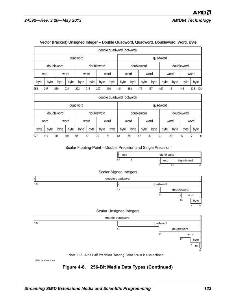
Streaming SIMD Extensions Media and Scientific Programming 133
24592—Rev. 3.20—May 2013 AMD64 Technology
Figure 4-8. 256-Bit Media Data Types (Continued)256-bit datatypes b.eps
Vector (Packed) Unsigned Integer – Double Quadword, Quadword, Doubleword, Word, ByteVector (Packed) Unsigned Integer – Double Quadword, Quadword, Doubleword, Word, Byte
135143151159167175183191199207215223231239247255 128
bytebytebytebytebytebytebytebytebytebytebytebytebytebytebytebyte
quadword
double quadword (octword)
quadword
doubleworddoubleworddoubleworddoubleword
wordwordwordwordwordwordwordword
71523313947556371798795103111119127 0
bytebytebytebytebytebytebytebytebytebytebytebytebytebytebytebyte
quadword
double quadword (octword)
quadword
doubleworddoubleworddoubleworddoubleword
wordwordwordwordwordwordwordword
127 0
Scalar Unsigned Integers
127
double quadword
15
31
63
quadword
doubleword
word
7
0
byte
bit
Scalar Signed Integers
127
double quadword
15
31
63
quadword
doubleword
word
7 0
byte
ss
s
s
s
s
s
s
s
s
31 22 0
Scalar Floating-Point – Double Precision and Single Precision
significand
exp significand63 51 exp
1
Note: 1) A 16 bit Half-Precision Floating-Point Scalar is also defined.

134 Streaming SIMD Extensions Media and Scientific Programming
AMD64 Technology 24592—Rev. 3.20—May 2013
Software can interpret the data types in ways other than those shown—such as bit fields or fractional numbers—but the instructions do not directly support such interpretations and software must handle them entirely on its own.
4.3.4 Operand Sizes and Overrides
Operand sizes for SSE instructions are determined by instruction opcodes. Some of these opcodes include an operand-size override prefix, but this prefix acts in a special way to modify the opcode and is considered an integral part of the opcode. The general use of the 66h operand-size override prefix described in “Instruction Prefixes” on page 76 does not apply to SSE instructions.
For details on the use of operand-size override prefixes in SSE instructions, see “Volume 4: 128-Bit and 256-Bit Media Instructions”.
4.4 Vector Operations
4.4.1 Integer Vector Operations
Figure 4-9 below shows an example of a typical two operand integer vector operation. In this example, each n-bit wide vector contains 16 integer elements. Note that the same mathematical operation is performed on all 16 elements in parallel. The computation of one element of the result vector does not affect the computation of any of the other result elements. For example, a carry out that could occur as a result of computing a sum is not added into the sum of the next most significant element of the vector.
In general, the result of a vector operation is a vector of the same width as the operands with the same number of elements. (Although there are instructions which increase or decrease the width and number of elements in the result.) There are instructions that operate on vectors of words, doublewords, quadwords and octwords. Both 128-bit and 256-bit wide vectors are supported. See Section 4.6. “Instruction Summary—Integer Instructions” on page 147 for more information on the supported 128-bit and 256-bit integer data types.
Most legacy SSE instructions support the specification of two operands. For these instructions the result overwrites the first operand as shown. The extended SSE set includes instructions that support two, three, or four vector operands. In these instructions, the result is generally written to a destination register specified by the instruction encoding.

Streaming SIMD Extensions Media and Scientific Programming 135
24592—Rev. 3.20—May 2013 AMD64 Technology
Figure 4-9. Mathematical Operations on Integer Vectors
4.4.2 Floating-Point Vector Operations
The SSE instruction set supports vectors of both single-precision and double-precision floating-point values in both 128-bit and 256-bit vector widths. See Section 4.6. “Instruction Summary—Integer Instructions” on page 147 for more information on the supported 128-bit and 256-bit data types.
Figure 4-10 shows an example of a parallel operation on two 256-bit vectors, each containing four 64-bit double-precision floating-point values. As in the integer vector operation, each element of the vector result is the product of the mathematical operation applied to corresponding elements of the source operands. The number of elements and parallel operations is 2, 4, or 8 depending on vector and element size.
Some SSE floating-point instructions support the specification of only two operands. For most of these instructions the result overwrites the first operand. The extended SSE instructions include instructions that support three or four operands. In most three and four operand instructions, the result is written to a separate destination register specified by the instruction encoding.
Figure 4-10. Mathematical Operations on Floating-Point Vectors
operand 1
. . . . . . . . . . . . . .. . . . . . . . . . . . . .
. . . . . . . . . . . . . .
n-1 0operand 2
n-1 0
operationoperation
int_vect_op.epsresultn-1 0
FP_vector_op256.epsresult255 0DP FPDP FP DP FPDP FP
operand 1255 0DP FPDP FP DP FPDP FP
operand 2255 0DP FPDP FP DP FPDP FP
op
op
op
op

136 Streaming SIMD Extensions Media and Scientific Programming
AMD64 Technology 24592—Rev. 3.20—May 2013
Integer and floating-point instructions can be freely intermixed in the same procedure. The floating-point instructions allow media applications such as 3D graphics to accelerate geometry, clipping, and lighting calculations. Pixel data are typically integer-based, although both integer and floating-point instructions are often required to operate completely on the data. For example, software can change the viewing perspective of a 3D scene through transformation matrices by using floating-point instructions in the same procedure that contains integer operations on other aspects of the graphics data.
For media and scientific programs that demand floating-point operations, it is often easier and more powerful to use SSE instructions. Such programs perform better than x87 floating-point programs, because the YMM/XMM register file is flat rather than stack-oriented, there are twice as many registers (in 64-bit mode), and SSE instructions can operate on four or eight times the number of floating-point operands as can x87 instructions. This ability to operate in parallel on multiple pairs of floating-point elements often makes it possible to remove local temporary variables that would otherwise be needed in x87 floating-point code.
4.5 Instruction Overview
4.5.1 Instruction Syntax
Each instruction has a mnemonic syntax used by assemblers to specify the operation and the operands to be used for source and destination (result) data.
Legacy SSE Instructions
The legacy SSE instructions accept two operands and generally have the following syntax:MNEMONIC xmm1, xmm2/mem128
Figure 4-11 below shows an example of the mnemonic syntax for a packed add bytes (PADDB) instruction.
Figure 4-11. Mnemonic Syntax for Typical Legacy SSE Instruction
v1_legacy_SSE_syntax.eps
Mnemonic
First Source Operandand Destination Operand
Second Source Operand
PADDB xmm1, xmm2/mem128

Streaming SIMD Extensions Media and Scientific Programming 137
24592—Rev. 3.20—May 2013 AMD64 Technology
This example shows the PADDB mnemonic followed by two operands, a 128-bit XMM register operand and another 128-bit XMM register or 128-bit memory operand. In most instructions that take two operands, the first (left-most) operand is both a source operand and the destination operand. The second (right-most) operand serves only as a source. Some instructions can have one or more prefixes that modify default properties, as described in “Instruction Prefixes” on page 212.
Extended SSE Instructions
The extended SSE instructions support operands of either 128 bits or 256 bits. They also support the specification of two, three, four, or five operands sourced from YMM/XMM registers, memory or immediate bytes. A three-operand 128-bit extended SSE instruction has the following syntax:
MNEMONIC xmm1, xmm2, xmm3/mem128
A three-operand 256-bit extended SSE instruction has the following syntax:MNEMONIC ymm1, ymm2, ymm3/mem256
Figure 4-12 below shows an example of the mnemonic syntax for the packed add bytes (VPADDB) instruction.
Figure 4-12. Mnemonic Syntax for Typical Extended SSE Instruction
This example shows the VPADDB mnemonic followed by three operands—a destination XMM register and two source operands. Instruction operand number 2 located in an XMM register is actually the first source operand and operand 3 is the second source operand. The second source operand may be located in an XMM register or in memory. The result of the vector add operation is placed in the specified destination register. Some instructions can have one or more prefixes that modify default properties, as described in “Instruction Prefixes” on page 212.
4.5.2 Mnemonics
Most mnemonics follow some general conventions:
As noted above, a V prepended to a mnemonic means that it is an AVX instruction.
v1_extend_128b_SSE_syntax.eps
Mnemonic
Destination Operand
First Source Operand
Second Source Operand
VPADDB xmm1, xmm2, xmm3/mem128

138 Streaming SIMD Extensions Media and Scientific Programming
AMD64 Technology 24592—Rev. 3.20—May 2013
The initial character string of the mnemonic (immediately after the possibly prepended V) represents the operation the instruction performs. An initial P in the string representing the operation stands for “Packed.” Subsequent character strings in various combinations either refer to operand types or indicate a variant of the basic operation. The following lists most of these conventions:
• A—Aligned• B—Byte• D—Doubleword• DQ—Double quadword• HL—High to low• LH—Low to high• L—Left• PD—Packed double-precision floating-point• PI—Packed integer• PS—Packed single-precision floating-point• Q—Quadword• R—Right• S—Signed, or Saturation, or Shift• SD—Scalar double-precision floating-point• SI—Signed integer• SS—Scalar single-precision floating-point, or Signed saturation• U—Unsigned, or Unordered, or Unaligned• US—Unsigned saturation• V—Intial letter designates an extended SSE instruction• W—Word• 2—to. Used in data type conversion instruction mnemonics.
Consider the example VPMULHUW. The initial V indicates that the instruction is an extended SSE instruction (in this case, an AVX instruction). It is a packed (that is, vector) multiply (P for packed and MUL for multiply) of unsigned words (U for unsigned and W for Word). Finally, the H refers to the fact that the high word of each intermediate double word result is written to the destination vector element.
4.5.3 Move Operations
Move instructions—along with unpack instructions—are among the most frequently used instructions in media procedures.
When moving between XMM registers, or between an XMM register and memory, each integer move instruction can copy up to 16 bytes of data. When moving between an XMM register and an MMX or
Streaming SIMD Extensions Media and Scientific Programming 139
24592—Rev. 3.20—May 2013 AMD64 Technology
GPR register, an integer move instruction can move up to 8 bytes of data. The packed floating-point move instructions can copy vectors of four single-precision or two double-precision floating-point operands in parallel.
Figure 4-13 below provides an overview of the basic move operations involving the XMM registers. Crosshatching in the figure represents bits in the destination register which may either be zero- extended or left unchanged in the move operation based on the instruction or (for one instruction) the source of the data. Data written to memory is never zero-extended. The AVX subset provides a number of 3-operand variants of the basic move instructions that merge additional data from a XMM register into the destination register. These are not shown in this figure nor are those instructions that extend fields in the destination register by duplicating bits from the source register.

140 Streaming SIMD Extensions Media and Scientific Programming
AMD64 Technology 24592—Rev. 3.20—May 2013
Figure 4-13. XMM Move Operations
v1_Vector_moves.eps
MMX Register XMM
XMM MMX Register
XMM XMM
Bits copied
Unchanged
mem
ory
XMM or Memory XMM
0
XMM GPR or Memory
mem
ory0
0
GPR or Memory XMM
mem
ory
XMM
mem
ory
XMM or Memory
Unchanged / 0 extend
0 extend0

Streaming SIMD Extensions Media and Scientific Programming 141
24592—Rev. 3.20—May 2013 AMD64 Technology
The SSE instruction set provides instructions that load a YMM register from memory, store the contents of a YMM register to memory, or move 256 bits from one register to another. Figure 4-14 below provides a schematic representation of these operations.
Figure 4-14. YMM Move Operations
Streaming-store versions of the move instructions (also known as non-temporal moves) bypass the cache when storing data that is accessed only once. This maximizes memory-bus utilization and minimizes cache pollution.
The move-mask instruction stores specific bytes from one vector, as selected by mask values in a second vector. Figure 4-15 below shows the (V)MASKMOVDQU operation. It can be used, for example, to handle end cases in block copies and block fills based on streaming stores.
Figure 4-15. Move Mask Operation
v1_256b_moves.eps
YMM
YMM or Memory
mem
ory
mem
ory YMM
YMM or Memory
p
write buffer
. . . . . . . . . . . . . .. . . . . . . . . . . . . .
127 0 p127 0
store addressDS:rDI
v1_Move_Mask.eps
0/1
0/1
memory
write combining

142 Streaming SIMD Extensions Media and Scientific Programming
AMD64 Technology 24592—Rev. 3.20—May 2013
4.5.4 Data Conversion and Reordering
SSE instructions support data conversion of vector elements, including conversions between integer and floating-point data types—located in YMM/XMM registers, MMX™ registers, GPR registers, or memory—and conversions of element-ordering or precision.
For example, the unpack instructions take two vector operands and interleave their low or high elements. Figure 4-16 shows an unpack and interleave operation on word-sized elements. This this case, (V)PUNPCKLWD. If operand 1 is a vector of unsigned integers and the left-hand source operand has elements whose value is zero, the operation converts each element in the low half of operand 1 to an integer data type of twice its original width. This would be a useful step prior to multiplying two integer vectors together to ensure that no overflow can occur during a vector multiply operation.
Figure 4-16. Unpack and Interleave Operation
There are also pack instructions, such as (V)PACKSSDW shown below in Figure 4-17, that convert each element in a pair of integer vectors to lower precision and pack them into the result vector.
Figure 4-17. Pack Operation
Vector-shift instructions are also provided. These instructions may be used to scale each element in an integer vector up or down.
v1_interleave.eps
operand 1
result
127 0operand 2
127 0
127 0
. .. .2 operand form
v1_pack.eps
operand 1
result
127 0
127 0
operand 2127 0
2 operand form

Streaming SIMD Extensions Media and Scientific Programming 143
24592—Rev. 3.20—May 2013 AMD64 Technology
Figure 4-18 shows one of many types of shuffle operations; in this case, PSHUFD. Here the second operand is a vector containing doubleword elements, and an immediate byte provides shuffle control for up to 256 permutations of the elements. Shuffles are useful, for example, in color imaging when computing alpha saturation of RGB values. In this case, a shuffle instruction can replicate an alpha value in a register so that parallel comparisons with three RGB values can be performed.
Figure 4-18. Shuffle Operation
The (V)PINSRB, (V)PINSRW, (V)PINSRD, and (V)PINSRQ instructions insert a byte, word, doubleword or quadword from a general-purpose register or memory into an XMM register, at a specified location. The legacy instructions leave the other elements in the XMM register unmodified. The extended instructions fill in the other elements from a second XMM source operand.
4.5.5 Matrix and Special Arithmetic Operations
The instruction set provides a broad assortment of vector add, subtract, multiply, divide, and square-root operations for use on matrices and other data structures common to media and scientific applications. It also provides special arithmetic operations including multiply-add, average, sum-of-absolute differences, reciprocal square-root, and reciprocal estimation.
SSE integer and floating-point instructions can perform several types of matrix-vector or matrix-matrix operations, such as addition, subtraction, multiplication, and accumulation. Efficient matrix multiplication is further supported with instructions that can first transpose the elements of matrix rows and columns. These transpositions can make subsequent accesses to memory or cache more efficient when performing arithmetic matrix operations.
Figure 4-19 on page 144 shows a Packed Multiply and Add instruction ((V)PMADDWD) which multiplies vectors of 16-bit integer elements to yield intermediate results of 32-bit elements, which are then summed pair-wise to yield four 32-bit elements. This operation can be used with one source operand (for example, a coefficient) taken from memory and the other source operand (for example, the data to be multiplied by that coefficient) taken from an XMM register. It can also be used together with a vector-add operation to accumulate dot product results (also called inner or scalar products), which are used in many media algorithms such as those required for finite impulse response (FIR) filters, one of the commonly used DSP algorithms.
v1_shuffle_op.eps
result
operand 1127 0
127 0
operand 2127 0

144 Streaming SIMD Extensions Media and Scientific Programming
AMD64 Technology 24592—Rev. 3.20—May 2013
Figure 4-19. Multiply-Add Operation
See Section 4.7.5. “Fused Multiply-Add Instructions” on page 201 for a discussion of floating-point fused multiply-add instructions.
The sum-of-absolute-differences instruction ((V)PSADBW), shown in Figure 4-20 is useful, for example, in computing motion-estimation algorithms for video compression.
Figure 4-20. Sum-of-Absolute-Differences Operation
v1_PMA_int.eps
operand 1
result
127 0 operand 2
127 0
127 0
intermediate result255 0. . . .
× × × ×
+ + + +
2 operand form
v1_PSABS_int.eps
. . . . . .. . . . . .. . . . . .. . . . . .
. . . . . . . . . . . .
. . . . . . . . . . . .
127 0operand 1 operand 2127 0
result00
127 0
low-orderintermediate result
high-orderintermediate result
ABS Δ ABS Δ ABS Δ ABS Δ
Σ Σ
2 operand form

Streaming SIMD Extensions Media and Scientific Programming 145
24592—Rev. 3.20—May 2013 AMD64 Technology
There is an instruction for computing the average of unsigned bytes or words. The instruction is useful for MPEG decoding, in which motion compensation involves many byte-averaging operations between and within macroblocks. In addition to speeding up these operations, the instruction also frees up registers and makes it possible to unroll the averaging loops.
Some of the arithmetic and pack instructions produce vector results in which each element saturates independently of the other elements in the result vector. Such results are clamped (limited) to the maximum or minimum value representable by the destination data type when the true result exceeds that maximum or minimum representable value. Saturating data is useful for representing physical-world data, such as sound and color. It is used, for example, when combining values for pixel coloring.
4.5.6 Branch Removal
Branching is a time-consuming operation that, unlike most SSE vector operations, does not exhibit parallel behavior (there is only one branch target, not multiple targets, per branch instruction). In many media applications, a branch involves selecting between only a few (often only two) cases. Such branches can be replaced with SSE vector compare and vector logical instructions that simulate predicated execution or conditional moves.
Figure 4-21 shows an example of a non-branching sequence that implements a two-way multiplexer—one that is equivalent to the ternary operator “?:” in C and C++. The comparable code sequence is explained in “Compare and Write Mask” on page 173.
The sequence begins with a vector compare instruction that compares the elements of two source operands in parallel and produces a mask vector containing elements of all 1s or 0s. This mask vector is ANDed with one source operand and ANDed-Not with the other source operand to isolate the desired elements of both operands. These results are then ORed to select the relevant elements from each operand. A similar branch-removal operation can be done using floating-point source operands.

146 Streaming SIMD Extensions Media and Scientific Programming
AMD64 Technology 24592—Rev. 3.20—May 2013
Figure 4-21. Branch-Removal Sequence
The min/max compare instructions, for example, are useful for clamping, such as color clamping in 3D graphics, without the need for branching. Figure 4-22 on page 146 illustrates a move-mask instruction ((V)PMOVMSKB) that copies sign bits to a general-purpose register (GPR). The instruction can extract bits from mask patterns, or zero values from quantized data, or sign bits—resulting in a byte that can be used for data-dependent branching.
Figure 4-22. Move Mask Operation
513-170.eps
operand 1 operand 2
FFFF 0000 0000 FFFFFFFF 0000 0000 FFFF
a3 a2 a1 a0a7 a6 a5 a4 b3 b2 b1 b0b7 b6 b5 b4
a3 0000 0000 a0a7 0000 0000 a4 0000 b2 b1 00000000 b6 b5 0000
And And-Not
Compare and Write Mask
a3 b2 b1 a0a7 b6 b5 a4
Or
127 0 127 0
127 0
513-157..eps
GPR XMM127 0
concatenate 16 most-significant bits
0
Streaming SIMD Extensions Media and Scientific Programming 147
24592—Rev. 3.20—May 2013 AMD64 Technology
4.6 Instruction Summary—Integer InstructionsThis section summarizes the SSE instructions that operate on scalar and packed integers. Software running at any privilege level can use any of the instructions discussed below given that hardware and system software support is provided and the appropriate instruction subset is enabled. Detection and enablement of instruction subsets is normally handled by operating system software. Hardware support for each instruction subset is indicated by processor feature bits. These are accessed via the CPUID instruction. See Volume 3 for details on the CPUID instruction and the feature bits associated with the SSE instruction set.
The SSE instructions discussed below include those that use the YMM/XMM registers as well as instructions that convert data from integer to floating-point formats. For more detail on each instruction, see individual instruction reference pages in the Instruction Reference chapter of Volume 4, “128-Bit and 256-Bit Media Instructions.”
For a summary of the floating-point instructions including instructions that convert from floating-point to integer formats, see “Instruction Summary—Floating-Point Instructions” on page 180.
The following subsections are organized by functional groups. These are:
• Data Transfer• Data Conversion• Data Reordering• Arithmetic• Enhanced Media• Shift and Rotate• Compare• Logical• Save and Restore
Most of the instructions described below have both a legacy and an AVX form. Generally the AVX form is functionally equivalent to the legacy form except for the affect of the instruction on the upper octword of the destination YMM register. The legacy form of an instruction leaves the upper octword of the YMM register that overlays the destination XMM register unchanged, while the AVX form always clears the upper octword.
The descriptions that follow apply equally to the legacy instruction and its 128-bit AVX form. Many of the AVX instructions also support a 256-bit version of the instruction that operates on the 256-bit data types. For the instructions which accept vector operands, the only difference in functionality between the 128-bit form and the 256-bit form is the number of elements operated upon in parallel (that is, the number of elements doubles). Other differences will be noted at the end of the discussion.
148 Streaming SIMD Extensions Media and Scientific Programming
AMD64 Technology 24592—Rev. 3.20—May 2013
4.6.1 Data Transfer
The data-transfer instructions copy data between a memory location, a YMM/XMM register, an MMX register, or a GPR. The MOV mnemonic, which stands for move, is a misnomer. A copy function is actually performed instead of a move. A new copy of the source value is created at the destination address, and the original copy remains unchanged at its source location.
4.6.1.1 Move• (V)MOVD—Move Doubleword or Quadword• (V)MOVQ—Move Quadword• (V)MOVDQA—Move Aligned Double Quadword• (V)MOVDQU—Move Unaligned Double Quadword• MOVDQ2Q—Move Quadword to Quadword• MOVQ2DQ—Move Quadword to Quadword• (V)LDDQU—Load Double Quadword Unaligned
When copying between YMM registers, or between a YMM register and memory, a move instruction can copy up to 32 bytes of data. When copying between XMM registers, or between an XMM register and memory, a move instruction can copy up to 16 bytes of data. When copying between an XMM register and an MMX or GPR register, a move instruction can copy up to 8 bytes of data.
The (V)MOVD instruction copies a 32-bit or 64-bit value from a GPR register or memory location to the low-order 32 or 64 bits of an XMM register, or from the low-order 32 or 64 bits of an XMM register to a 32-bit or 64-bit GPR or memory location. If the source operand is a GPR or memory location, the source is zero-extended to 128 bits in the XMM register. If the source is an XMM register, only the low-order 32 or 64 bits of the source are copied to the destination.The 64-bit (long) form of (V)MOVD is aliased as (V)MOVQ.
The (V)MOVQ instruction copies a 64-bit value from memory to the low quadword of an XMM register, or from the low quadword of an XMM register to memory, or between the low quadwords of two XMM registers. If the source is in memory and the destination is an XMM register, the source is zero-extended to 128 bits in the XMM register.
The (V)MOVDQA instruction copies a 128-bit value from memory to an XMM register, or from an XMM register to memory, or between two XMM registers. If either the source or destination is a memory location, the memory address must be aligned. The (V)MOVDQU instruction does the same, except for unaligned operands. The (V)LDDQU instruction is virtually identical in operation to the (V)MOVDQU instruction. The (V)LDDQU instruction moves a double quadword of data from a 128-bit memory operand into a destination XMM register.
The VMOVDQA and VMOVDQU instructions have 256-bit forms which copy a 256-bit value from memory to a YMM register, or from a YMM register to memory, or between two YMM registers. VLDDQU has a 256-bit form that loads a 256-bit value from memory.

Streaming SIMD Extensions Media and Scientific Programming 149
24592—Rev. 3.20—May 2013 AMD64 Technology
The MOVDQ2Q instruction copies the low-order 64-bit value in an XMM register to an MMX register. The MOVQ2DQ instruction copies a 64-bit value from an MMX register to the low-order 64 bits of an XMM register, with zero-extension to 128 bits.
Figure 4-23 below diagrams the capabilities of these instructions. (V)LDDQU and the 128-bit forms of the extended instructions are not shown.

150 Streaming SIMD Extensions Media and Scientific Programming
AMD64 Technology 24592—Rev. 3.20—May 2013
Figure 4-23. Integer Move Operations
v1_Integer_Moves.eps
MOVDQ2Q
XMM Register127 0
MMX Register63 0
Destination SourceYMM Register or MemoryYMM Register
mem
ory
256 0256 0VMOVDQAVMOVDQU
YMM Register or Memory YMM Register
mem
ory VMOVDQA
VMOVDQU
MOVQ
MOVD
XMM Register127 0
GPR Register or Memory63 0
mem
ory
MOVQ
MOVD
XMM Register127 0GPR Register or Memory
63 0
mem
ory0
0
MOVQ2DQ
XMM Register127 0
MMX Register63 0
0
Bits copiedBits not copied 0 extend0
MOVDQAMOVDQU
MOVQ
127 0
mem
ory
127 0 XMM Register or MemoryXMM Register
0
MOVDQAMOVDQU
MOVQ
127 0XMM Register
mem
ory
127 0XMM Register or Memory
0

Streaming SIMD Extensions Media and Scientific Programming 151
24592—Rev. 3.20—May 2013 AMD64 Technology
The move instructions are in many respects similar to the assignment operator in high-level languages. The simplest example of their use is for initializing variables. To initialize a register to 0, however, rather than using a MOVx instruction it may be more efficient to use the (V)PXOR instruction with identical destination and source operands.
4.6.1.2 Move Non-Temporal
The move non-temporal instructions are streaming-store instructions. They minimize pollution of the cache.
• (V)MOVNTDQ—Move Non-temporal Double Quadword• (V)MOVNTDQA—Move Non-temporal Double Quadword Aligned• (V)MASKMOVDQU—Masked Move Double Quadword Unaligned
The (V)MOVNTDQ instruction stores its source operand (a 128-bit XMM register value or a 256-bit YMM register value) to a 128-bit or 256-bit memory location. (V)MOVNTDQ indicates to the processor that its data is non-temporal, which assumes that the referenced data will be used only once and is therefore not subject to cache-related overhead (as opposed to temporal data, which assumes that the data will be accessed again soon and should be cached). The non-temporal instructions use weakly-ordered, write-combining buffering of write data, and they minimize cache pollution. The exact method by which cache pollution is minimized depends on the hardware implementation of the instruction. For further information, see “Memory Optimization” on page 97 and “Use Streaming Stores” on page 228.
The function of the MOVNTDQA instruction is the same as MOVNTDQ instruction but its exception behavior differs. An attempt by MOVNTDQA to store to an unaligned memory address causes a #GP or invokes the alignment checking mechanism depending on the setting of the MXCSR[MM] bit. An attempt by the VMOVNTDQA to store to an unaligned memory address causes a #GP.
(V)MASKMOVDQU is also a non-temporal instruction. It stores bytes from the first operand, as selected by the mask value in the second operand. Bytes are written to a memory location specified in the rDI and DS registers. The first and second operands are both XMM registers. The address may be unaligned. Figure 4-24 shows the (V)MASKMOVDQU operation. It is useful for the handling of end cases in block copies and block fills based on streaming stores.

152 Streaming SIMD Extensions Media and Scientific Programming
AMD64 Technology 24592—Rev. 3.20—May 2013
Figure 4-24. (V)MASKMOVDQU Move Mask Operation
4.6.1.3 Move Mask• (V)PMOVMSKB—Packed Move Mask Byte
The (V)PMOVMSKB instruction moves the most-significant bit of each byte in an XMM register to the low-order word of a 32-bit or 64-bit general-purpose register, with zero-extension. The instruction is useful for extracting bits from mask patterns, or zero values from quantized data, or sign bits—resulting in a byte that can be used for data-dependent branching. Figure 4-25 below shows the (V)PMOVMSKB operation.
Figure 4-25. (V)PMOVMSKB Move Mask Operation
operand 1
write buffer
. . . . . . . . . . . . . .. . . . . . . . . . . . . .
127 0 operand 2127 0
store addressDS:rDI
v1_Move_Mask.eps
0/1
0/1
memory
write combining
513-157..eps
GPR XMM127 0
concatenate 16 most-significant bits
0

Streaming SIMD Extensions Media and Scientific Programming 153
24592—Rev. 3.20—May 2013 AMD64 Technology
4.6.1.4 Vector Conditional Moves
XOP instruction set includes the vector conditional move instructions:
• VPCMOV—Vector Conditional Moves• VPPERM—Packed Permute Bytes
The VPCMOV instruction implements the C/C++ language ternary ‘?’ operator a bit level. Each bit of the destination YMM/XMM register is copied from the corresponding bit of either the first or second source operand based on the value of the corresponding bit of a third source operand. This instruction has both 128-bit and 256-bit forms. The VPCMOV instruction allows either the second or the third operand to be source from memory, based on the XOP.W bit.
The VPPERM instruction performs vector permutation on a packed array of 32 bytes composed of two 16-byte input operands. The VPPERM instruction replaces each destination byte with 00h, FFh, or one of the 32 bytes of the packed array. A byte selected from the array may have an additional operation such as NOT or bit reversal applied to it, before it is written to the destination. The action for each destination byte is determined by a corresponding control byte. The VPPERM instruction allows either the second 16-byte input array or the control array to be memory based, per the XOP.W bit.
4.6.2 Data Conversion
The integer data-conversion instructions convert integer operands to floating-point operands. These instructions take integer source operands. For data-conversion instructions that take floating-point source operands, see “Data Conversion” on page 185. For data-conversion instructions that take 64-bit source operands, see Section 5.6.4. “Data Conversion” on page 251 and Section 5.7.2. “Data Conversion” on page 265.
4.6.2.1 Convert Integer to Floating-Point
These instructions convert integer data types in a YMM/XMM register or memory into floating-point data types in a YMM/XMM register.
• (V)CVTDQ2PS—Convert Packed Doubleword Integers to Packed Single-Precision Floating-Point
• (V)CVTDQ2PD—Convert Packed Doubleword Integers to Packed Double-Precision Floating-Point
The (V)CVTDQ2PS instruction converts four (eight, for 256-bit form) 32-bit signed integer values in the second operand to four (eight) single-precision floating-point values and writes the converted values to the specified XMM (YMM) register. If the result of the conversion is an inexact value, the value is rounded. The (V)CVTDQ2PD instruction is analogous to (V)CVTDQ2PS except that it converts two (four) 64-bit signed integer values to two (four) double-precision floating-point values.
4.6.2.2 Convert MMX Integer to Floating-Point
These instructions convert integer data types in MMX registers or memory into floating-point data types in XMM registers.

154 Streaming SIMD Extensions Media and Scientific Programming
AMD64 Technology 24592—Rev. 3.20—May 2013
• CVTPI2PS—Convert Packed Doubleword Integers to Packed Single-Precision Floating-Point• CVTPI2PD—Convert Packed Doubleword Integers to Packed Double-Precision Floating-Point
The CVTPI2PS instruction converts two 32-bit signed integer values in an MMX register or a 64-bit memory location to two single-precision floating-point values and writes the converted values in the low-order 64 bits of an XMM register. The high-order 64 bits of the XMM register are not modified.
The CVTPI2PD instruction is analogous to CVTPI2PS except that it converts two 32-bit signed integer values to two double-precision floating-point values and writes the converted values in the full 128 bits of an XMM register.
Before executing a CVTPI2x instruction, software should ensure that the MMX registers are properly initialized so as to prevent conflict with their aliased use by x87 floating-point instructions. This may require clearing the MMX state, as described in “Accessing Operands in MMX™ Registers” on page 227.
For a description of SSE instructions that convert in the opposite direction—floating-point to integer in MMX registers—see “Convert Floating-Point to MMX™ Integer” on page 187. For a summary of instructions that operate on MMX registers, see Chapter 5, “64-Bit Media Programming.”
4.6.2.3 Convert GPR Integer to Floating-Point
These instructions convert integer data types in GPR registers or memory into floating-point data types in XMM registers.
• (V)CVTSI2SS—Convert Signed Doubleword or Quadword Integer to Scalar Single-Precision Floating-Point
• (V)CVTSI2SD—Convert Signed Doubleword or Quadword Integer to Scalar Double-Precision Floating-Point
The (V)CVTSI2SS instruction converts a 32-bit or 64-bit signed integer value in a general-purpose register or memory location to a single-precision floating-point value and writes the converted value to the low-order 32 bits of an XMM register. The legacy version of the instruction leaves the three high-order doublewords of the destination XMM register unmodified. The extended version of the instruction copies the three high-order doublewords of another XMM register (specified in the first source operand) to the destination.
The (V)CVTSI2SD instruction converts a 32-bit or 64-bit signed integer value in a general-purpose register or memory location to a double-precision floating-point value and writes the converted value to the low-order 64 bits of an XMM register. The legacy version of the instruction leaves the high-order 64 bits in the destination XMM register unmodified. The extended version of the instruction copies the upper 64 bits of another XMM register (specified in the first source operand) to the destination.

Streaming SIMD Extensions Media and Scientific Programming 155
24592—Rev. 3.20—May 2013 AMD64 Technology
4.6.2.4 Convert Packed Integer Format
A common operation on packed integers is the conversion by zero or sign extension of packed integers into wider data types. These instructions convert from a smaller packed integer type to a larger integer type.
• (V)PMOVSXBW—Sign extend the lower 8-bit integer of each packed word element into packed signed word integers.
• (V)PMOVZXBW—Zero extend the lower 8-bit integer of each packed word element into packed signed word integers.
• (V)PMOVSXBD—Sign extend the lower 8-bit integer of each packed doubleword element into packed signed doubleword integers.
• (V)PMOVZXBD—Zero extend the lower 8-bit integer of each packed doubleword element into packed signed doubleword integers.
• (V)PMOVSXWD—Sign extend the lower 16-bit integer of each packed doubleword element into packed signed doubleword integers.
• (V)PMOVZXWD—Zero extend the lower 16-bit integer of each packed doubleword element into packed signed doubleword integers.
• (V)PMOVSXBQ—Sign extend the lower 8-bit integer of each packed quadword element into packed signed quadword integers.
• (V)PMOVZXBQ—Zero extend the lower 8-bit integer of each packed quadword element into packed signed quadword integers.
• (V)PMOVSXWQ—Sign extend the lower 16-bit integer of each packed quadword element into packed signed quadword integers.
• (V)PMOVZXWQ—Zero extend the lower 16-bit integer of each packed quadword element into packed signed quadword integers.
• (V)PMOVSXDQ—Sign extend the lower 32-bit integer of each packed quadword element into packed signed quadword integers.
• (V)PMOVZXDQ—Zero extend the lower 32-bit integer of each packed quadword element into packed signed quadword integers.
The source operand is from either an XMM register or memory. The destination is an XMM register. When accessing memory, no alignment is required for any of the instructions unless alignment checking is enabled. In which case, all conversions must be aligned to the width of the memory reference.
4.6.3 Data Reordering
The integer data-reordering instructions pack, unpack, interleave, extract, insert, and shuffle the elements of vector operands.

156 Streaming SIMD Extensions Media and Scientific Programming
AMD64 Technology 24592—Rev. 3.20—May 2013
4.6.3.1 Pack with Saturation
These instructions pack larger data types into smaller data types, thus halving the precision of each element in a vector operand.
• (V)PACKSSDW—Pack with Saturation Signed Doubleword to Word• (V)PACKUSDW—Pack with Unsigned Saturation Doubleword to Word • (V)PACKSSWB—Pack with Saturation Signed Word to Byte• (V)PACKUSWB—Pack with Saturation Signed Word to Unsigned Byte
The (V)PACKSSDW instruction converts each of the four signed doubleword integers in its two source operands (an XMM register, and another XMM register or 128-bit memory location) into signed word integers and packs the converted values into the destination operand (an XMM register). The (V)PACKUSDW instruction does the same operation except that it converts signed doubleword integers into unsigned (rather than signed) word integers.
The (V)PACKSSWB instruction converts each of the eight signed word integers in its two source operands (an XMM register, and another XMM register or 128-bit memory location) into signed 8-bit integers and packs the converted values into the destination operand (an XMM register).The (V)PACKUSWB instruction does the same operation except that it converts signed word integers into unsigned (rather than signed) bytes.
Figure 4-26 shows an example of a (V)PACKSSDW instruction. The operation merges vector elements of 2x size into vector elements of 1x size, thus reducing the precision of the vector-element data types. Any results that would otherwise overflow or underflow are saturated (clamped) at the maximum or minimum representable value, respectively, as described in Section . “Saturation” on page 119.
Figure 4-26. (V)PACKSSDW Pack Operation
Conversion from higher-to-lower precision is often needed, for example, by multiplication operations in which the higher-precision format is used for source operands in order to prevent possible overflow, and the lower-precision format is the desired format for the next operation.
v1_PACKSSDW.eps
operand 1
result
127 0
127 0
operand 2127 0
2 operand form

Streaming SIMD Extensions Media and Scientific Programming 157
24592—Rev. 3.20—May 2013 AMD64 Technology
4.6.3.2 Packed Blend
These instructions select vector elements from one of two source operands to be copied to the corresponding elements of the destination.
• (V)PBLENDVB—Variable Blend Packed Bytes• (V)PBLENDW—Blend Packed Words
(V)PBLENDVB and (V)PBLENDW instructions copy bytes or words from either of two sources to the specified destination register based on selector bits in a mask. If the mask bit is a 0 the corresponding element is copied from the first source operand. If the mask bit is a 1, the element is copied from the second source operand. For (V)PBLENDVB the mask is composed of the most significant bits of the elements of a third source operand. For (V)PBLENDW the mask is specified via an immediate byte. For the legacy form of (V)PBLENDVB, the mask is contained in the implicit operand register XMM0. For the extended form, the mask is contained in an XMM register specified via encoding in the instruction.
The first source operand is an XMM register. The second source operand is either another XMM register or a 128-bit memory location. For the legacy instructions, the destination is also the first source operand. For the extended forms, the destination is a separately specified XMM register.
4.6.3.3 Unpack and Interleave
These instructions interleave vector elements from the high or low halves of two integer source operands. They can be used to double the precision of operands.
• (V)PUNPCKHBW—Unpack and Interleave High Bytes• (V)PUNPCKHWD—Unpack and Interleave High Words• (V)PUNPCKHDQ—Unpack and Interleave High Doublewords• (V)PUNPCKHQDQ—Unpack and Interleave High Quadwords• (V)PUNPCKLBW—Unpack and Interleave Low Bytes• (V)PUNPCKLWD—Unpack and Interleave Low Words• (V)PUNPCKLDQ—Unpack and Interleave Low Doublewords• (V)PUNPCKLQDQ—Unpack and Interleave Low Quadwords
The (V)PUNPCKHBW instruction copies the eight high-order bytes from its two source operands (an XMM register, and another XMM register or 128-bit memory location) and interleaves them into the 128-bit destination operand (an XMM register). The bytes in the low-order half of the source operands are ignored. The (V)PUNPCKHWD, (V)PUNPCKHDQ, and (V)PUNPCKHQDQ instructions perform analogous operations for words, doublewords, and quadwords in the source operands, packing them into interleaved words, interleaved doublewords, and interleaved quadwords in the destination operand.
The (V)PUNPCKLBW, (V)PUNPCKLWD, (V)PUNPCKLDQ, and (V)PUNPCKLQDQ instructions are analogous to their high-element counterparts except that they take elements from the low

158 Streaming SIMD Extensions Media and Scientific Programming
AMD64 Technology 24592—Rev. 3.20—May 2013
quadword of each source vector and ignore elements in the high quadword. Depending on the hardware implementation, if the source operand for (V)PUNPCKLx and (V)PUNPCKHx instructions is in memory, only the low 64 bits of the operand may be loaded.
Figure 4-27 shows an example of the (V)PUNPCKLWD instruction. The elements are taken from the low half of the source operands. Elements from the second source operand are placed to the left of elements from first source operand.
Figure 4-27. (V)PUNPCKLWD Unpack and Interleave Operation
If operand 2 is a vector consisting of all zero-valued elements, the unpack instructions perform the function of expanding vector elements of 1x size into vector elements of 2x size. Conversion from lower-to-higher precision is often needed, for example, prior to multiplication operations in which the higher-precision format is used for source operands in order to prevent possible overflow during multiplication.
If both source operands are of identical value, the unpack instructions can perform the function of duplicating adjacent elements in a vector.
The (V)PUNPCKx instructions can be used in a repeating sequence to transpose rows and columns of an array. For example, such a sequence could begin with (V)PUNPCKxWD and be followed by (V)PUNPCKxQD. These instructions can also be used to convert pixel representation from RGB format to color-plane format, or to interleave interpolation elements into a vector.
As noted above, and depending on the hardware implementation, the width of the memory access performed by the memory-operand forms of (V)PUNPCKLBW, (V)PUNPCKLWD, (V)PUNPCKLDQ, and (V)PUNPCKLQDQ may be 64 bits, but the width of the memory access of the memory-operand forms of (V)PUNPCKHBW, (V)PUNPCKHWD, (V)PUNPCKHDQ, and (V)PUNPCKHQDQ may be 128 bits. Thus, the alignment constraints for (V)PUNPCKLx instructions may be less restrictive than the alignment constraints for (V)PUNPCKHx instructions. For details, see the documentation for particular hardware implementations of the architecture.
Another advantage of using (V)PUNPCKLx rather than (V)PUNPCKHx—also depending on the hardware implementation—is that it may help avoid potential size mismatches if a particular hardware
v1_PUNPCKLWD.eps
operand 1
result
127 0operand 2
127 0
127 0
. .. .2 operand form

Streaming SIMD Extensions Media and Scientific Programming 159
24592—Rev. 3.20—May 2013 AMD64 Technology
implementation uses load-to-store forwarding. In such cases, store data from either a quadword store or the lower quadword of a double-quadword store could be forwarded to (V)PUNPCKLx instructions, but only store data from a double-quadword store could be forwarded to (V)PUNPCKHx instructions.
4.6.3.4 Extract and Insert
These instructions copy a word element from a vector, in a manner specified by an immediate operand.
• EXTRQ—Extract Field from Register• INSERTQ—Insert Field• (V)PEXTRB—Extract Packed Byte• (V)PEXTRW—Extract Packed Word• (V)PEXTRD—Extract Packed Doubleword• (V)PEXTRQ—Extract Packed Quadword• (V)PINSRB—Packed Insert Byte• (V)PINSRW—Packed Insert Word• (V)PINSRD—Packed Insert Doubleword• (V)PINSRQ—Packed Insert Quadword
The EXTRQ instruction extracts specified bits from the lower 64 bits of the destination XMM register. The extracted bits are saved in the least-significant bit positions of the destination and the remaining bits in the lower 64 bits of the destination register are cleared to 0. The upper 64 bits of the destination register are undefined.
The INSERTQ instruction inserts a specified number of bits from the lower 64 bits of the source operand into a specified bit position of the lower 64 bits of the destination operand. No other bits in the lower 64 bits of the destination are modified. The upper 64 bits of the destination are undefined.
The (V)PEXTRB, (V)PEXTRW, (V)PEXTRD, and (V)PEXTRQ instructions extract a single byte, word, doubleword, or quadword from an XMM register, as selected by the immediate-byte operand, and write it to memory or to the low-order bits of a general-purpose register with zero-extension to 32 bit or 64 bits as required. These instructions are useful for loading computed values, such as table-lookup indices, into general-purpose registers where the values can be used for addressing tables in memory.
The (V)PINSRB, (V)PINSRW, (V)PINSRD, and (V)PINSRQ instructions insert a byte, word, or doubleword value from the low-order bits of a general-purpose register or from a memory location into an XMM register. The location in the destination register is selected by the immediate-byte operand. For the legacy form, the other elements of the destination register are not modified. For the extended form, the other elements are filled in from a second source XMM register. As an example of these instructions, Figure 4-28 below provides a schematic the (V)PINSRD instruction.

160 Streaming SIMD Extensions Media and Scientific Programming
AMD64 Technology 24592—Rev. 3.20—May 2013
Figure 4-28. (V)PINSRD Operation
4.6.3.5 Shuffle
These instructions reorder the elements of a vector.
• (V)PSHUFB—Packed Shuffle Byte• (V)PSHUFD—Packed Shuffle Doublewords• (V)PSHUFHW—Packed Shuffle High Words• (V)PSHUFLW—Packed Shuffle Low Words
The (V)PSHUFB instruction copies bytes from the first source operand (an XMM register) to the destination or clears bytes in the destination as specified by control bytes in the second source operand (either an XMM register or a 128-bit memory location). Each byte in the second operand controls how the corresponding byte is the destination is selected or cleared. For the legacy form, the first source XMM register is also the destination. For the extended form, a separate destination register is specified in the instruction.
The (V)PSHUFD instruction fills each doubleword of the first operand (an XMM register) by copying any one of the doublewords in the second operand (an XMM register or 128-bit memory location). An immediate byte operand specifies for each double word of the destination which doubleword to copy. The ordering of the shuffle can occur in one of 256 possible ways. Figure 4-29 below shows one of the 256 possible shuffle operations.
v1_VPINSRD.eps
127 0DWDW DWDW
Source operand 2 (extended form)127 0DWDW DWDW
Source operand 1
DW
mem
oryGPR
Immediate
select
Destination XMM Register
XMM Register
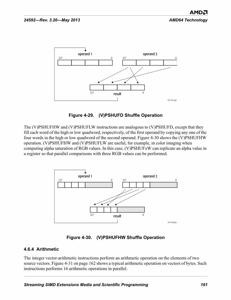
Streaming SIMD Extensions Media and Scientific Programming 161
24592—Rev. 3.20—May 2013 AMD64 Technology
Figure 4-29. (V)PSHUFD Shuffle Operation
The (V)PSHUFHW and (V)PSHUFLW instructions are analogous to (V)PSHUFD, except that they fill each word of the high or low quadword, respectively, of the first operand by copying any one of the four words in the high or low quadword of the second operand. Figure 4-30 shows the (V)PSHUFHW operation. (V)PSHUFHW and (V)PSHUFLW are useful, for example, in color imaging when computing alpha saturation of RGB values. In this case, (V)PSHUFxW can replicate an alpha value in a register so that parallel comparisons with three RGB values can be performed.
Figure 4-30. (V)PSHUFHW Shuffle Operation
4.6.4 Arithmetic
The integer vector-arithmetic instructions perform an arithmetic operation on the elements of two source vectors. Figure 4-31 on page 162 shows a typical arithmetic operation on vectors of bytes. Such instructions performs 16 arithmetic operations in parallel.
513-151.eps
result
operand 1127 0
127 0
operand 2127 0
513-167.eps
result
operand 1127 0
127 0
operand 2127 0

162 Streaming SIMD Extensions Media and Scientific Programming
AMD64 Technology 24592—Rev. 3.20—May 2013
Figure 4-31. Arithmetic Operation on Vectors of Bytes
4.6.4.1 Addition• (V)PADDB—Packed Add Bytes• (V)PADDW—Packed Add Words• (V)PADDD—Packed Add Doublewords• (V)PADDQ—Packed Add Quadwords• (V)PADDSB—Packed Add with Saturation Bytes• (V)PADDSW—Packed Add with Saturation Words• (V)PADDUSB—Packed Add Unsigned with Saturation Bytes• (V)PADDUSW—Packed Add Unsigned with Saturation Words
The (V)PADDB, (V)PADDW, (V)PADDD, and (V)PADDQ instructions add each packed 8-bit ((V)PADDB), 16-bit ((V)PADDW), 32-bit ((V)PADDD), or 64-bit ((V)PADDQ) integer element in the second operand (an XMM register or a 128-bit memory location) to the corresponding, same-sized integer element in the first operand (an XMM register) and write the integer result to the corresponding, same-sized element of the destination. Figure 4-31 diagrams a (V)PADDB operation (where the operation is addition). These instructions operate on both signed and unsigned integers. However, if the result overflows, the carry is ignored and only the low-order byte, word, doubleword, or quadword of each result is written to the destination. The (V)PADDD instruction can be used together with (V)PMADDWD (page 165) to implement dot products. In the legacy form, the first source XMM register is also the destination. The extended form specifies a separate destination XMM register encoded in the instruction.
The (V)PADDSB and (V)PADDSW instructions add each 8-bit ((V)PADDSB) or 16-bit ((V)PADDSW) signed integer element in the second operand (an XMM register or a 128-bit memory location) to the corresponding, same-sized signed integer element in the first operand (an XMM register) and write the signed integer result to the corresponding, same-sized element of the destination. For each result in the destination, if the result is larger than the largest, or smaller than the smallest, representable 8-bit ((V)PADDSB) or 16-bit ((V)PADDSW) signed integer, the result is saturated to the largest or smallest representable value, respectively.
Source operand 1
. . . . . . . . . . . . . .. . . . . . . . . . . . . .
. . . . . . . . . . . . . .
127 0 Source operand 2127 0
operationoperation
v1_byte_vector_ops.epsresult127 0
2 operand form

Streaming SIMD Extensions Media and Scientific Programming 163
24592—Rev. 3.20—May 2013 AMD64 Technology
The (V)PADDUSB and (V)PADDUSW instructions perform saturating-add operations analogous to the (V)PADDSB and (V)PADDSW instructions, except on unsigned integer elements.
In the legacy form of these instructions, the first source XMM register is also the destination. The extended form specifies a separate destination XMM register encoded in the instruction.
4.6.4.2 Subtraction• (V)PSUBB—Packed Subtract Bytes• (V)PSUBW—Packed Subtract Words• (V)PSUBD—Packed Subtract Doublewords• (V)PSUBQ—Packed Subtract Quadword• (V)PSUBSB—Packed Subtract with Saturation Bytes• (V)PSUBSW—Packed Subtract with Saturation Words• (V)PSUBUSB—Packed Subtract Unsigned and Saturate Bytes• (V)PSUBUSW—Packed Subtract Unsigned and Saturate Words
The subtraction instructions perform operations analogous to the addition instructions.
The (V)PSUBB, (V)PSUBW, (V)PSUBD, and (V)PSUBQ instructions subtract each 8-bit ((V)PSUBB), 16-bit ((V)PSUBW), 32-bit ((V)PSUBD), or 64-bit ((V)PSUBQ) integer element in the second operand from the corresponding, same-sized integer element in the first operand and write the integer result to the corresponding, same-sized element of the destination. For vectors of n number of elements, the operation is:
result[i] = operand1[i] - operand2[i]
where: i = 0 to n – 1
These instructions operate on both signed and unsigned integers. However, if the result underflows, the borrow is ignored and only the low-order byte, word, doubleword, or quadword of each result is written to the destination.
The (V)PSUBSB and (V)PSUBSW instructions subtract each 8-bit ((V)PSUBSB) or 16-bit ((V)PSUBSW) signed integer element in the second operand from the corresponding, same-sized signed integer element in the first operand and write the signed integer result to the corresponding, same-sized element of the destination. For each result in the destination, if the result is larger than the largest, or smaller than the smallest, representable 8-bit ((V)PSUBSB) or 16-bit ((V)PSUBSW) signed integer, the result is saturated to the largest or smallest representable value, respectively.
The (V)PSUBUSB and (V)PSUBUSW instructions perform saturating-add operations analogous to the (V)PSUBSB and (V)PSUBSW instructions, except on unsigned integer elements.
In the legacy form of these instructions, the first source XMM register is also the destination. The extended form specifies a separate destination XMM register encoded in the instruction.
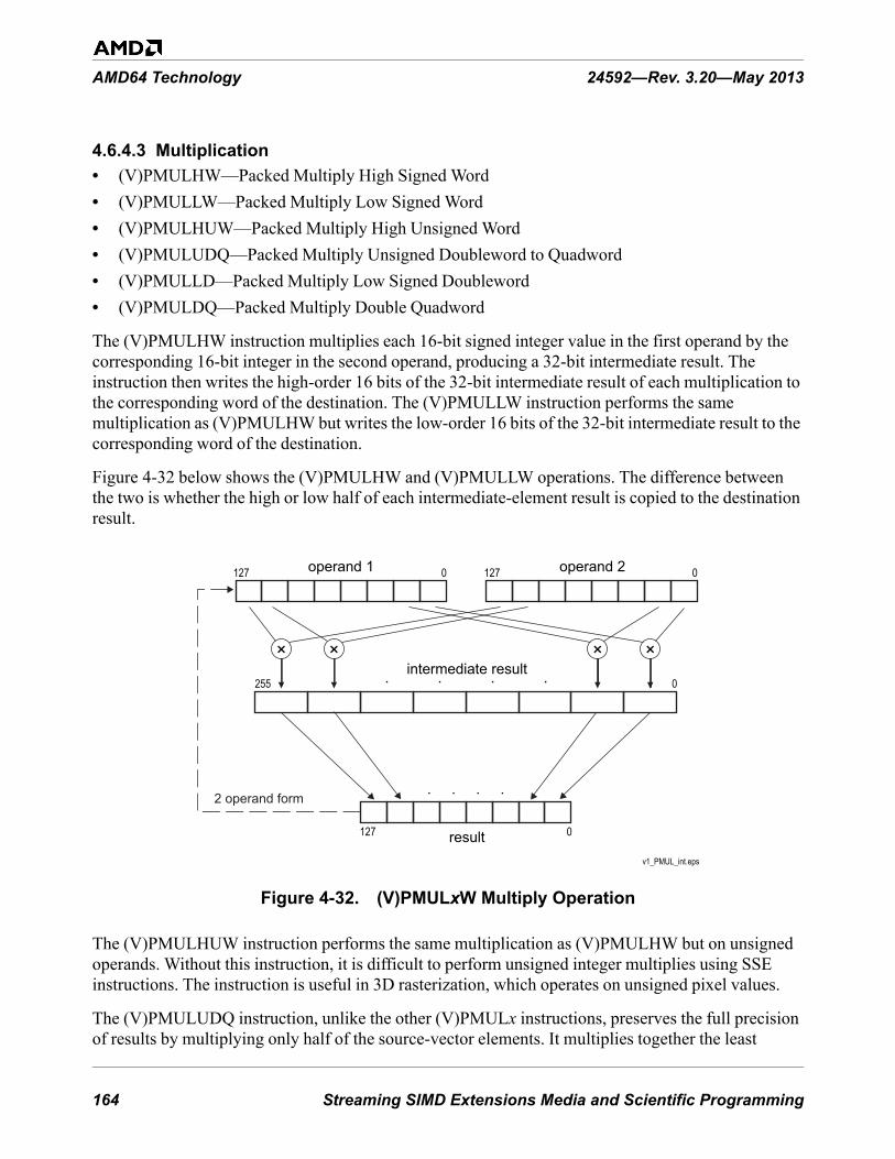
164 Streaming SIMD Extensions Media and Scientific Programming
AMD64 Technology 24592—Rev. 3.20—May 2013
4.6.4.3 Multiplication• (V)PMULHW—Packed Multiply High Signed Word• (V)PMULLW—Packed Multiply Low Signed Word• (V)PMULHUW—Packed Multiply High Unsigned Word• (V)PMULUDQ—Packed Multiply Unsigned Doubleword to Quadword• (V)PMULLD—Packed Multiply Low Signed Doubleword• (V)PMULDQ—Packed Multiply Double Quadword
The (V)PMULHW instruction multiplies each 16-bit signed integer value in the first operand by the corresponding 16-bit integer in the second operand, producing a 32-bit intermediate result. The instruction then writes the high-order 16 bits of the 32-bit intermediate result of each multiplication to the corresponding word of the destination. The (V)PMULLW instruction performs the same multiplication as (V)PMULHW but writes the low-order 16 bits of the 32-bit intermediate result to the corresponding word of the destination.
Figure 4-32 below shows the (V)PMULHW and (V)PMULLW operations. The difference between the two is whether the high or low half of each intermediate-element result is copied to the destination result.
Figure 4-32. (V)PMULxW Multiply Operation
The (V)PMULHUW instruction performs the same multiplication as (V)PMULHW but on unsigned operands. Without this instruction, it is difficult to perform unsigned integer multiplies using SSE instructions. The instruction is useful in 3D rasterization, which operates on unsigned pixel values.
The (V)PMULUDQ instruction, unlike the other (V)PMULx instructions, preserves the full precision of results by multiplying only half of the source-vector elements. It multiplies together the least
v1_PMUL_int.eps
operand 1
result
127 0 operand 2
127 0
127 0
intermediate result255 0. . . .
. . . .
× × × ×
2 operand form

Streaming SIMD Extensions Media and Scientific Programming 165
24592—Rev. 3.20—May 2013 AMD64 Technology
significant doubleword of each quadword in the two source operands, writes the full 64-bit result of the low-order multiply to the low-order quadword of the destination, and writes the high-order product to the high-order quadword of the destination. Figure 4-33 below shows a (V)PMULUDQ operation.
Figure 4-33. (V)PMULUDQ Multiply Operation
See “Shift and Rotate” on page 171 for shift instructions that can be used to perform multiplication and division by powers of 2.
The (V)PMULLD instruction returns four lower 32-bits of the 64-bit results of signed 32-bit integer multiplies.
The (V)PMULDQ instruction returns two 64-bit signed result of signed 32-bit integer multiplies.
In the legacy form of these instructions, the first source XMM register is also the destination. The extended form specifies a separate destination XMM register encoded in the instruction.
4.6.4.4 Multiply-Add
This instruction multiplies the elements of two source vectors and adds their intermediate results in a single operation.
• (V)PMADDWD—Packed Multiply Words and Add Doublewords
The (V)PMADDWD instruction multiplies each 16-bit signed value in the first operand (an XMM register) by the corresponding 16-bit signed value in the second operand (either an XMM register or a 128-bit memory location). The instruction then adds the adjacent 32-bit intermediate results of each multiplication, and writes the 32-bit result of each addition into the corresponding doubleword of the destination. For vectors of n number of source elements (src), m number of destination elements (dst), and n = 2m, the operation is:
dst[j] = ((src1[i] * src2[i]) + (src1[i+1] * src2[i+1]))
where: j = 0 to m – 1i = 2j
v1_PMULUDQ.eps
operand 1
result
127 0 operand 2
127 0
127 0
× ×2 operand form

166 Streaming SIMD Extensions Media and Scientific Programming
AMD64 Technology 24592—Rev. 3.20—May 2013
(V)PMADDWD thus performs four signed multiply-adds in parallel. Figure 4-34 below diagrams the operation.
Figure 4-34. (V)PMADDWD Multiply-Add Operation
(V)PMADDWD can be used with one source operand (for example, a coefficient) taken from memory and the other source operand (for example, the data to be multiplied by that coefficient) taken from an XMM register. The instruction can also be used together with the (V)PADDD instruction (page 162) to compute dot products. Scaling can be done, before or after the multiply, using a vector-shift instruction (page 171).
If all four of the 16-bit source operands used to produce a 32-bit multiply-add result have the value 8000h, the result is represented as 8000_0000h, because the maximum negative 16-bit value of 8000h multiplied by itself equals 4000_0000h, and 4000_0000h added to 4000_0000h equals 8000_0000h. The result of multiplying two negative numbers should be a positive number, but 8000_0000h is the maximum possible 32-bit negative number rather than a positive number.
For PMADDWD, the first source XMM register is also the destination. VPMADDWD specifies a separate destination XMM register encoded in the instruction.
4.6.5 Enhanced Media
4.6.5.1 Multiply-Add and Accumulate
The multiply and accumulate and multiply, add and accumulate instructions operate on and produce packed signed integer values. These instructions allow the accumulation of results from (possibly) many iterations of similar operations without a separate intermediate addition operation to update the accumulator register.
v1_PMA_int.eps
operand 1
result
127 0 operand 2
127 0
127 0
intermediate result255 0. . . .
× × × ×
+ + + +
2 operand form

Streaming SIMD Extensions Media and Scientific Programming 167
24592—Rev. 3.20—May 2013 AMD64 Technology
The operation of a typical XOP integer multiply and accumulate instruction is shown in Figure 4-35 on page 167. The multiply and accumulate instructions operate on and produce packed signed integer values. These instructions first multiply the value in the first source operand by the corresponding value in the second source operand. Each signed integer product is then added to the corresponding value in the third source operand, which is the accumulator and is identical to the destination operand. The results may or may not be saturated prior to being written to the destination register, depending on the instruction.
Figure 4-35. Operation of Multiply and Accumulate Instructions
The XOP instruction extensions provide the following integer multiply and accumulate instructions.
• VPMACSSWW—Packed Multiply Accumulate Signed Word to Signed Word with Saturation• VPMACSWW—Packed Multiply Accumulate Signed Word to Signed Word• VPMACSSWD—Packed Multiply Accumulate Signed Word to Signed Doubleword with
Saturation• VPMACSWD—Packed Multiply Accumulate Signed Word to Signed Doubleword• VPMACSSDD—Packed Multiply Accumulate Signed Doubleword to Signed Doubleword with
Saturation• VPMACSDD—Packed Multiply Accumulate Signed Doubleword to Signed Doubleword• VPMACSSDQL—Packed Multiply Accumulate Signed Low Doubleword to Signed Quadword
with Saturation
src1
127 96 95 64 63 32 31 0
src2
src3127 96 95 64 63 32 31 0
(saturate)
dest127 96 95 64 63 32 31 0
multiply
add
multiply
add
(saturate)
multiplymultiply
add
add(accumulate)(accumulate)
(accumulate)(accumulate)
(saturate) (saturate)
127 96 95 64 63 32 31 0

168 Streaming SIMD Extensions Media and Scientific Programming
AMD64 Technology 24592—Rev. 3.20—May 2013
• VPMACSSDQH—Packed Multiply Accumulate Signed High Doubleword to Signed Quadword with Saturation
• VPMACSDQL—Packed Multiply Accumulate Signed Low Doubleword to Signed Quadword• VPMACSDQH—Packed Multiply Accumulate Signed High Doubleword to Signed Quadword
The operation of the multiply, add and accumulate instructions is illustrated in Figure 4-36.
The multiply, add and accumulate instructions first multiply each packed signed integer value in the first source operand by the corresponding packed signed integer value in the second source operand. The odd and even adjacent resulting products are then added. Each resulting sum is then added to the corresponding packed signed integer value in the third source operand.
Figure 4-36. Operation of Multiply, Add and Accumulate Instructions
The XOP instruction set provides the following integer multiply, add and accumulate instructions.
• VPMADCSSWD—Packed Multiply Add and Accumulate Signed Word to Signed Doubleword with Saturation
• VPMADCSWD—Packed Multiply Add and Accumulate Signed Word to Signed Doubleword
src1127 112 111 96 95 80 79 64 63 48 47 32 31 16 15 0
src2127 112 111 96 95 80 79 64 63 48 47 32 31 16 15 0
src3
127 96 95 64 63 32 31 0
multiplymultiply
multiplymultiply
multiply multiply
multiplymultiply
add
add
dest127 96 95 64 63 32 31 0
(saturate)
add add
add
(saturate)
add
(saturate)
add
(saturate)
add
[accumulate][accumulate]
[accumulate][accumulate]

Streaming SIMD Extensions Media and Scientific Programming 169
24592—Rev. 3.20—May 2013 AMD64 Technology
4.6.5.2 Packed Integer Horizontal Add and Subtract
The packed horizontal add and subtract signed byte instructions successively add adjacent pairs of signed integer values from the source XMM register or 128-bit memory operand and pack the (sign extended) integer result of each addition in the destination.
• VPHADDBW—Packed Horizontal Add Signed Byte to Signed Word• VPHADDBD—Packed Horizontal Add Signed Byte to Signed Doubleword• VPHADDBQ—Packed Horizontal Add Signed Byte to Signed Quadword• VPHADDDQ—Packed Horizontal Add Signed Doubleword to Signed Quadword• VPHADDUBW—Packed Horizontal Add Unsigned Byte to Word• VPHADDUBD—Packed Horizontal Add Unsigned Byte to Doubleword• VPHADDUBQ—Packed Horizontal Add Unsigned Byte to Quadword• VPHADDUWD—Packed Horizontal Add Unsigned Word to Doubleword• VPHADDUWQ—Packed Horizontal Add Unsigned Word to Quadword• VPHADDUDQ—Packed Horizontal Add Unsigned Doubleword to Quadword• VPHADDWD—Packed Horizontal Add Signed Word to Signed Doubleword• VPHADDWQ—Packed Horizontal Add Signed Word to Signed Quadword• VPHSUBBW—Packed Horizontal Subtract Signed Byte to Signed Word• VPHSUBWD—Packed Horizontal Subtract Signed Word to Signed Doubleword• VPHSUBDQ—Packed Horizontal Subtract Signed Doubleword to Signed Quadword
4.6.5.3 Average• (V)PAVGB—Packed Average Unsigned Bytes• (V)PAVGW—Packed Average Unsigned Words
The (V)PAVGx instructions compute the rounded average of each unsigned 8-bit ((V)PAVGB) or 16-bit ((V)PAVGW) integer value in the first operand and the corresponding, same-sized unsigned integer in the second operand and write the result in the corresponding, same-sized element of the destination. The rounded average is computed by adding each pair of operands, adding 1 to the temporary sum, and then right-shifting the temporary sum by one bit-position. For vectors of n number of elements, the operation is:
operand1[i] = ((operand1[i] + operand2[i]) + 1) ÷ 2
where: i = 0 to n – 1
The (V)PAVGB instruction is useful for MPEG decoding, in which motion compensation performs many byte-averaging operations between and within macroblocks. In addition to speeding up these operations, (V)PAVGB can free up registers and make it possible to unroll the averaging loops.
In the legacy form of these instructions, the first source XMM register is also the destination. The extended form specifies a separate destination XMM register encoded in the instruction.
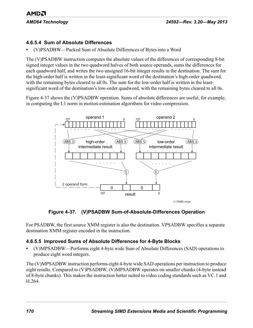
170 Streaming SIMD Extensions Media and Scientific Programming
AMD64 Technology 24592—Rev. 3.20—May 2013
4.6.5.4 Sum of Absolute Differences• (V)PSADBW—Packed Sum of Absolute Differences of Bytes into a Word
The (V)PSADBW instruction computes the absolute values of the differences of corresponding 8-bit signed integer values in the two quadword halves of both source operands, sums the differences for each quadword half, and writes the two unsigned 16-bit integer results in the destination. The sum for the high-order half is written in the least-significant word of the destination’s high-order quadword, with the remaining bytes cleared to all 0s. The sum for the low-order half is written in the least-significant word of the destination’s low-order quadword, with the remaining bytes cleared to all 0s.
Figure 4-37 shows the (V)PSADBW operation. Sums of absolute differences are useful, for example, in computing the L1 norm in motion-estimation algorithms for video compression.
Figure 4-37. (V)PSADBW Sum-of-Absolute-Differences Operation
For PSADBW, the first source XMM register is also the destination. VPSADBW specifies a separate destination XMM register encoded in the instruction.
4.6.5.5 Improved Sums of Absolute Differences for 4-Byte Blocks• (V)MPSADBW—Performs eight 4-byte wide Sum of Absolute Differences (SAD) operations to
produce eight word integers.
The (V)MPSADBW instruction performs eight 4-byte wide SAD operations per instruction to produce eight results. Compared to (V)PSADBW, (V)MPSADBW operates on smaller chunks (4-byte instead of 8-byte chunks). This makes the instruction better suited to video coding standards such as VC.1 and H.264.
v1_PSABS_int.eps
. . . . . .. . . . . .. . . . . .. . . . . .
. . . . . . . . . . . .
. . . . . . . . . . . .
127 0operand 1 operand 2127 0
result00
127 0
low-orderintermediate result
high-orderintermediate result
ABS Δ ABS Δ ABS Δ ABS Δ
Σ Σ
2 operand form

Streaming SIMD Extensions Media and Scientific Programming 171
24592—Rev. 3.20—May 2013 AMD64 Technology
(V)MPSADBW performs four times the number of absolute difference operations than that of (V)PSADBW (per instruction). This can improve performance for dense motion searches.
(V)MPSADBW uses a 4-byte wide field from a source operand. The offset of the 4-byte field within the 128-bit source operand is specified by two immediate control bits. (V)MPSADBW produces eight 16-bit SAD results. Each 16-bit SAD result is formed from overlapping pairs of 4 bytes in the destination with the 4-byte field from the source operand. (V)MPSADBW uses eleven consecutive bytes in the destination operand. Its offset is specified by a control bit in the immediate byte (i.e. the offset can be from byte 0 or from byte 4).
For MPSADBW, the first source XMM register is also the destination. VMPSADBW specifies a separate destination XMM register encoded in the instruction.
4.6.6 Shift and Rotate
The vector-shift instructions are useful for scaling vector elements to higher or lower precision, packing and unpacking vector elements, and multiplying and dividing vector elements by powers of 2.
4.6.6.1 Left Logical Shift• (V)PSLLW—Packed Shift Left Logical Words• (V)PSLLD—Packed Shift Left Logical Doublewords• (V)PSLLQ—Packed Shift Left Logical Quadwords• (V)PSLLDQ—Packed Shift Left Logical Double Quadword
The (V)PSLLW, (V)PSLLD, and (V)PSLLQ instructions left-shift each of the 16-bit, 32-bit, or 64-bit values, respectively, in the first operand by the number of bits specified in the second operand. The instructions then write each shifted value into the corresponding, same-sized element of the destination. The low-order bits that are emptied by the shift operation are cleared to 0. The first operand is an XMM register. The second operand can be an XMM register, 128-bit memory location, or immediate byte.
In integer arithmetic, left logical shifts effectively multiply unsigned operands by positive powers of 2. Thus, for vectors of n number of elements, the operation is:
operand1[i] = operand1[i] * 2operand2
where: i = 0 to n – 1
The (V)PSLLDQ instruction differs from the other three left-shift instructions because it operates on bytes rather than bits. It left-shifts the 128-bit (double quadword) value in an XMM register by the number of bytes specified in an immediate byte value.
In the legacy form of these instructions, the first source XMM register is also the destination. The extended form specifies a separate destination XMM register encoded in the instruction.
4.6.6.2 Right Logical Shift• (V)PSRLW—Packed Shift Right Logical Words

172 Streaming SIMD Extensions Media and Scientific Programming
AMD64 Technology 24592—Rev. 3.20—May 2013
• (V)PSRLD—Packed Shift Right Logical Doublewords• (V)PSRLQ—Packed Shift Right Logical Quadwords• (V)PSRLDQ—Packed Shift Right Logical Double Quadword
The (V)PSRLW, (V)PSRLD, and (V)PSRLQ instructions right-shift each of the 16-bit, 32-bit, or 64-bit values, respectively, in the first operand by the number of bits specified in the second operand. The instructions then write each shifted value into the corresponding, same-sized element of the destination. The high-order bits that are emptied by the shift operation are cleared to 0. The first operand is an XMM register. The second operand can be an XMM register, 128-bit memory location, or immediate byte.
In integer arithmetic, right logical bit-shifts effectively divide unsigned operands by positive powers of 2, or they divide positive signed operands by positive powers of 2. Thus, for vectors of n number of elements, the operation is:
operand1[i] = operand1[i] ÷ 2operand2
where: i = 0 to n – 1
The (V)PSRLDQ instruction differs from the other three right-shift instructions because it operates on bytes rather than bits. It right-shifts the 128-bit (double quadword) value in an XMM register by the number of bytes specified in an immediate byte value. (V)PSRLDQ can be used, for example, to move the high 8 bytes of an XMM register to the low 8 bytes of the register. In some implementations, however, (V)PUNPCKHQDQ may be a better choice for this operation.
In the legacy form of these instructions, the first source XMM register is also the destination. The extended form specifies a separate destination XMM register encoded in the instruction.
4.6.6.3 Right Arithmetic Shift• (V)PSRAW—Packed Shift Right Arithmetic Words• (V)PSRAD—Packed Shift Right Arithmetic Doublewords
The (V)PSRAx instructions right-shift each of the 16-bit ((V)PSRAW) or 32-bit ((V)PSRAD) values in the first operand by the number of bits specified in the second operand. The instructions then write each shifted value into the corresponding, same-sized element of the destination. The high-order bits that are emptied by the shift operation are filled with the sign bit of the initial value.
In integer arithmetic, right arithmetic shifts effectively divide signed operands by positive powers of 2. Thus, for vectors of n number of elements, the operation is:
operand1[i] = operand1[i] ÷ 2operand2
where: i = 0 to n – 1
In the legacy form of these instructions, the first source XMM register is also the destination. The extended form specifies a separate destination XMM register encoded in the instruction.

Streaming SIMD Extensions Media and Scientific Programming 173
24592—Rev. 3.20—May 2013 AMD64 Technology
4.6.6.4 Packed Integer Shifts
The packed integer shift instructions shift each element of the vector in the first source XMM or 128-bit memory operand by the amount specified by a control byte contained in the least significant byte of the corresponding element of the second source operand. The result of each shift operation is returned in the destination XMM register. This allows load-and-shift from memory operations, with either the source operand or the shift-count operand being memory-based, as indicated by the XOP.W bit. The XOP instruction set provides the following packed integer shift instructions:
• VPSHLB—Packed Shift Logical Bytes• VPSHLW—Packed Shift Logical Words• VPSHLD—Packed Shift Logical Doublewords• VPSHLQ—Packed Shift Logical Quadwords• VPSHAB—Packed Shift Arithmetic Bytes• VPSHAW—Packed Shift Arithmetic Words• VPSHAD—Packed Shift Arithmetic Doublewords• VPSHAQ—Packed Shift Arithmetic Quadwords
There is no legacy form for these instructions.
4.6.6.5 Packed Integer Rotate
There are two variants of the packed integer rotate instructions. The first is identical to that described above (see “Packed Integer Shifts”). In the second variant, the control byte is supplied as an 8-bit immediate operand that specifies a single rotate amount for every element in the first source operand.
The XOP instruction set provides the following packed integer rotate instructions:
• VPROTB—Packed Rotate Bytes• VPROTW—Packed Rotate Words• VPROTD—Packed Rotate Doublewords• VPROTQ—Packed Rotate Quadwords
There is no legacy form for these instructions.
4.6.7 Compare
The integer vector-compare instructions compare two operands, and they either write a mask or they write the maximum or minimum value.
4.6.7.1 Compare and Write Mask• (V)PCMPEQB—Packed Compare Equal Bytes• (V)PCMPEQW—Packed Compare Equal Words• (V)PCMPEQD—Packed Compare Equal Doublewords

174 Streaming SIMD Extensions Media and Scientific Programming
AMD64 Technology 24592—Rev. 3.20—May 2013
• (V)PCMPEQQ—Packed Compare Equal Quadwords• (V)PCMPGTB—Packed Compare Greater Than Signed Bytes• (V)PCMPGTW—Packed Compare Greater Than Signed Words• (V)PCMPGTD—Packed Compare Greater Than Signed Doublewords• (V)PCMPGTQ—Packed Compare Greater Than Signed Quadwords
The (V)PCMPEQx and (V)PCMPGTx instructions compare corresponding bytes, words, doublewords, or quadwords in the two source operands. The first source operand is an XMM register, and the second source operand is either an XMM register or a 128-bit memory location. The instructions then write a mask of all 1s or 0s for each compare into the corresponding, same-sized element of the destination. Figure 4-38 on page 174 shows a (V)PCMPEQB compare operation. It performs 16 compares in parallel.
Figure 4-38. (V)PCMPEQB Compare Operation
For the (V)PCMPEQx instructions, if the compared values are equal, the result mask is all 1s. If the values are not equal, the result mask is all 0s. For the (V)PCMPGTx instructions, if the signed value in the first operand is greater than the signed value in the second operand, the result mask is all 1s. If the value in the first operand is less than or equal to the value in the second operand, the result mask is all 0s.
In the legacy form of these instructions, the first source XMM register is also the destination. The extended form specifies a separate destination XMM register encoded in the instruction.
By specifying the same register for both operands, (V)PCMPEQx can be used to set the bits in an XMM register to all 1s.
513-168.epsresult
operand 1127 0
127 0
operand 2127 0
imm8
compare
all 1s or 0s all 1s or 0s
compare
. . . . . . . . . . . . . .. . . . . . . . . . . . . .
. . . . . . . . . . . . . .

Streaming SIMD Extensions Media and Scientific Programming 175
24592—Rev. 3.20—May 2013 AMD64 Technology
Figure 4-21 on page 146 shows an example of a non-branching sequence that implements a two-way multiplexer—one that is equivalent to the following sequence of ternary operators in C or C++:r0 = a0 > b0 ? a0 : b0r1 = a1 > b1 ? a1 : b1r2 = a2 > b2 ? a2 : b2r3 = a3 > b3 ? a3 : b3r4 = a4 > b4 ? a4 : b4r5 = a5 > b5 ? a5 : b5r6 = a6 > b6 ? a6 : b6r7 = a7 > b7 ? a7 : b7
Assuming xmm0 contains the vector a, and xmm1 contains the vector b, the above C sequence can be implemented with the following assembler sequence:MOVQ xmm3, xmm0PCMPGTW xmm3, xmm1 ; a > b ? 0xffff : 0PAND xmm0, xmm3 ; a > b ? a: 0PANDN xmm3, xmm1 ; a > b ? 0 : bPOR xmm0, xmm3 ; r = a > b ? a: b
In the above sequence, (V)PCMPGTW, (V)PAND, (V)PANDN, and (V)POR operate, in parallel, on all four elements of the vectors.
4.6.7.2 Compare and Write Minimum or Maximum• (V)PMAXUB—Packed Maximum Unsigned Bytes• (V)PMAXUW—Packed Maximum Unsigned Words• (V)PMAXUD— Packed Maximum Unsigned Doublewords• (V)PMAXSB—Packed Maximum Signed Bytes• (V)PMAXSW—Packed Maximum Signed Words• (V)PMAXSD—Packed Maximum Signed Doublewords• (V)PMINUB—Packed Minimum Unsigned Bytes• (V)PMINUW—Packed Minimum Unsigned Words• (V)PMINUD—Packed Minimum Unsigned Doublewords• (V)PMINSB—Packed Minimum Signed Bytes• (V)PMINSW—Packed Minimum Signed Words• (V)PMINSD—Packed Minimum Signed Doublewords
The (V)PMAXUB, (V)PMAXUW, and (V)PMAXUD and the (V)PMINUB, (V)PMINUW, (V)PMINUD instructions compare each of the 8-bit, 16-bit, or 32-bit unsigned integer values in the first operand with the corresponding 8-bit, 16-bit, or 32-bit unsigned integer values in the second operand. The first source operand is an XMM register, the second is either an XMM register or a 128-bit memory location. The instructions then write the maximum ((V)PMAXUB) or minimum ((V)PMINUB) of the two values for each comparison into the corresponding element of the destination.

176 Streaming SIMD Extensions Media and Scientific Programming
AMD64 Technology 24592—Rev. 3.20—May 2013
The (V)PMAXSB, (V)PMAXSW, (V)PMAXSD and the (V)PMINSB, (V)PMINSW, (V)PMINSD instructions perform operations analogous to the (V)PMAXUB and (V)PMINUB instructions, except on 16-bit signed integer values.
In the legacy form of these instructions, the first source XMM register is also the destination. The extended form specifies a separate destination XMM register encoded in the instruction.
4.6.7.3 Packed Integer Comparison and Predicate Generation• VPCOMUB—Compare Vector Unsigned Bytes• VPCOMUW—Compare Vector Unsigned Words• VPCOMUD—Compare Vector Unsigned Doublewords• VPCOMUQ—Compare Vector Unsigned Quadwords• VPCOMB—Compare Vector Signed Bytes• VPCOMW—Compare Vector Signed Words• VPCOMD—Compare Vector Signed Doublewords• VPCOMQ—Compare Vector Signed Quadwords
These XOP comparison instructions compare packed integer values in the first source XMM register with corresponding packed integer values in the second source XMM register or 128-bit memory. The type of comparison is specified by the immediate-byte operand. The resulting predicate is placed in the destination XMM register. If the condition is true, all bits in the corresponding field in the destination register are set to 1s; otherwise all bits in the field are set to 0s.
Table 4-10. Immediate Operand Values for Unsigned Vector Comparison Operations
The integer comparison and predicate generation instructions compare corresponding packed signed or unsigned bytes in the first and second source operands and write the result of each comparison in the corresponding element of the destination. The result of each comparison is a value of all 1s (TRUE) or all 0s (FALSE). The type of comparison is specified by the three low-order bits of the immediate-byte operand.
Immediate Operand Byte Comparison Operation
Bits 7:3 Bits 2:0
00000b
000b Less Than001b Less Than or Equal010b Greater Than011b Greater Than or Equal100b Equal101b Not Equal110b False111b True

Streaming SIMD Extensions Media and Scientific Programming 177
24592—Rev. 3.20—May 2013 AMD64 Technology
4.6.7.4 String and Text Processing Instructions• (V)PCMPESTRI — Packed compare explicit-length strings, return index in ECX/RCX• (V)PCMPESTRM — Packed compare explicit-length strings, return mask in XMM0• (V)PCMPISTRI — Packed compare implicit-length strings, return index in ECX/RCX• (V)PCMPISTRM — Packed compare implicit-length strings, return mask in XMM0
These four instructions use XMM registers to process string or text elements of up to 128-bits (16 bytes or 8 words). Each instruction uses an immediate byte to support an extensive set of programmable controls. These instructions return the result of processing each pair of string elements using either an index or a mask. Each instruction has an extended SSE (AVX) counterpart with the same functionality.
The capabilities of these instructions include:
• Handling string/text fragments consisting of bytes or words, either signed or unsigned• Support for partial string or fragments less than 16 bytes in length, using either explicit length or
implicit null-termination• Four types of string compare operations on word/byte elements• Up to 256 compare operations performed in a single instruction on all string/text element pairs• Built-in aggregation of intermediate results from comparisons• Programmable control of processing on intermediate results• Programmable control of output formats in terms of an index or mask• Bidirectional support for the index format• Support for two mask formats: bit or natural element width• Does not require 16-byte alignment for memory operand
All four instructions require the use of an immediate byte to control operation. The first source operand is an XMM register The second source operand can be either an XMM register or a 128-bit memory location. The immediate byte provides programmable control with the following attributes:
• Input data format• Compare operation mode• Intermediate result processing• Output selection
Depending on the output format associated with the instruction, the text/string processing instructions implicitly uses either a general-purpose register (ECX/RCX) or an XMM register (XMM0) to return the final result. Neither of the source operands are modified.
Two of the four text-string processing instructions specify string length explicitly. They use two general-purpose registers (EDX, EAX) to specify the number of valid data elements (either word or byte) in the source operands. The other two instructions specify valid string elements using null

178 Streaming SIMD Extensions Media and Scientific Programming
AMD64 Technology 24592—Rev. 3.20—May 2013
termination. A data element is considered valid only if it has a lower index than the least significant null data element.
These instructions do not perform alignment checking on memory operands.
4.6.8 Logical
The vector-logic instructions perform Boolean logic operations, including AND, OR, and exclusive OR.
4.6.8.1 AND• (V)PAND—Packed Logical Bitwise AND• (V)PANDN—Packed Logical Bitwise AND NOT• (V)PTEST—Packed Bit Test
The (V)PAND instruction performs a logical bitwise AND of the values in the first and second operands and writes the result to the destination. The first operand is an XMM register. The second is either an XMM register or a 128-bit memory location.
The (V)PANDN instruction inverts the first operand (creating a ones-complement of the operand), ANDs it with the second operand, and writes the result to the destination. Table 4-11 shows an example.
The packed bit test instruction (V)PTEST is similar to the general-purpose instruction TEST. Using the first source operand as a bit mask, (V)PTEST may be used to test whether the bits in the second source operand that correspond to the set bits in the mask are all zeros. If this is true rFLAGS[ZF] is set. If all the bits in the second source operand that correspond to the cleared bits in the mask are all zeros, then the rFLAGS[CF] bit is set.
Because neither source operand is modified, (V)PTEST simplifies branching operations, such as branching on signs of packed floating-point numbers, or branching on zero fields.
VPTEST has both a 128-bit and a 256-bit form.
4.6.8.2 OR and Exclusive OR• (V)POR—Packed Logical Bitwise OR
Table 4-11. Example PANDN Bit Values
Operand1 Bit Operand1 Bit(Inverted) Operand2 Bit PANDN
Result Bit1 0 1 01 0 0 00 1 1 10 1 0 0

Streaming SIMD Extensions Media and Scientific Programming 179
24592—Rev. 3.20—May 2013 AMD64 Technology
• (V)PXOR—Packed Logical Bitwise Exclusive OR
The (V)POR instruction performs a logical bitwise OR of the values in the first and second operands and writes the result to the destination. The first source operand is an XMM register and the second is either an XMM register or a 128-bit memory location.
The (V)PXOR instruction is analogous to (V)POR except it performs a bit-wise exclusive OR of the two source operands. (V)PXOR can be used to clear all bits in an XMM register by specifying the same register for both operands.
In the legacy form of these instructions, the first source XMM register is also the destination. The extended form specifies a separate destination XMM register encoded in the instruction.
4.6.9 Save and Restore State
These instructions save and restore the entire processor state for legacy SSE instructions.
4.6.9.1 Save and Restore 128-Bit, 64-Bit, and x87 State• FXSAVE—Save XMM, MMX, and x87 State• FXRSTOR—Restore XMM, MMX, and x87 State
The FXSAVE and FXRSTOR instructions save and restore the entire 512-byte processor state for legacy SSE instructions, 64-bit media instructions, and x87 floating-point instructions. The architecture supports two memory formats for FXSAVE and FXRSTOR, a 512-byte 32-bit legacy format and a 512-byte 64-bit format. Selection of the 32-bit or 64-bit format is determined by the effective operand size for the FXSAVE and FXRSTOR instructions. For details, see “FXSAVE and FXRSTOR Instructions” in Volume 2.
4.6.9.2 Save and Restore Extended Processor Context• XSAVE—Save Extended Processor Context.• XRSTOR—Restore Extended Processor Context.
The XSAVE and XRSTOR instructions provide a flexible means of saving and restoring not only the x87, 64-bit media, and legacy SSE state, but also the extended SSE context. The first 512 bytes of the save area supports the FXSAVE/FXRSTOR 512-byte 64-bit format. Subsequent bytes support an extensible data structure to be used for extended processor context such as the extended SSE context including the contents of the YMM registers. For details, see “XSAVE and XRSTOR Instructions” in Volume 4.
4.6.9.3 Save and Restore Control and Status• (V)STMXCSR—Store MXCSR Control/Status Register• (V)LDMXCSR—Load MXCSR Control/Status Register
The (V)STMXCSR and (V)LDMXCSR instructions save and restore the 32-bit contents of the MXCSR register. For further information, see Section 4.2.2. “MXCSR Register” on page 113.

180 Streaming SIMD Extensions Media and Scientific Programming
AMD64 Technology 24592—Rev. 3.20—May 2013
4.7 Instruction Summary—Floating-Point InstructionsThis section summarizes the SSE instructions that operate on scalar and packed floating-point values. Software running at any privilege level can use any of the instructions discussed below, given that hardware and system software support is provided and the appropriate instruction subset is enabled. Detection and enablement of instruction subsets is normally handled by operating system software. Hardware support for each instruction subset is indicated by processor feature bits. These are accessed via the CPUID instruction. See Volume 3 for details on the CPUID instruction and the feature bits associated with the SSE instruction set.
The SSE instructions discussed below include those that use the YMM/XMM registers as well as instructions that convert data from floating-point to integer formats. For more detail on each instruction, see individual instruction reference pages in the Instruction Reference chapter of Volume 4, “128-Bit and 256-Bit Media Instructions.”
For a summary of the integer SSE instructions including instructions that convert from integer to floating-point formats, see Section 4.6. “Instruction Summary—Integer Instructions” on page 147.
For a summary of the 64-bit media floating-point instructions, see “Instruction Summary—Floating-Point Instructions” on page 264. For a summary of the x87 floating-point instructions, see “Instruction Summary” on page 304.
The following subsections are organized by functional groups. These are:
• Data Transfer• Data Conversion• Data Reordering• Arithmetic• Fused Multiply-Add Instructions• Compare• Logical
Most of the instructions described below have both legacy and AVX versions. For the 128-bit media instructions, the extended version is functionally equivalent to the legacy version except legacy instructions leave the upper octword of the YMM register that overlays the destination XMM register unchanged, while the 128-bit AVX instruction always clears the upper octword. The descriptions that follow apply equally to the legacy instruction and its extended AVX version. Generally, for those extended instructions that have 256-bit variants, the number of elements operated upon in parallel doubles. Other differences will be noted at the end of the discussion.
4.7.1 Data Transfer
The data-transfer instructions copy 32-bit, 64-bit, 128-bit, or 256-bit data from memory to a YMM/XMM register, from a YMM/XMM register to memory, or from one register to another. The MOV mnemonic, which stands for move, is a misnomer. A copy function is actually performed instead

Streaming SIMD Extensions Media and Scientific Programming 181
24592—Rev. 3.20—May 2013 AMD64 Technology
of a move. A new copy of the source value is created at the destination address, and the original copy remains unchanged at its source location.
4.7.1.1 Move• (V)MOVAPS—Move Aligned Packed Single-Precision Floating-Point• (V)MOVAPD—Move Aligned Packed Double-Precision Floating-Point• (V)MOVUPS—Move Unaligned Packed Single-Precision Floating-Point• (V)MOVUPD—Move Unaligned Packed Double-Precision Floating-Point• (V)MOVHPS—Move High Packed Single-Precision Floating-Point• (V)MOVHPD—Move High Packed Double-Precision Floating-Point• (V)MOVLPS—Move Low Packed Single-Precision Floating-Point• (V)MOVLPD—Move Low Packed Double-Precision Floating-Point• (V)MOVHLPS—Move Packed Single-Precision Floating-Point High to Low• (V)MOVLHPS—Move Packed Single-Precision Floating-Point Low to High• (V)MOVSS—Move Scalar Single-Precision Floating-Point• (V)MOVSD—Move Scalar Double-Precision Floating-Point• (V)MOVDDUP—Move Double-Precision and Duplicate• (V)MOVSLDUP—Move Single-Precision High and Duplicate• (V)MOVSHDUP—Move Single-Precision Low and Duplicate
Figure 4-39 on page 182 summarizes the capabilities of the floating-point move instructions except (V)MOVDDUP, (V)MOVSLDUP, (V)MOVSHDUP which are described in the following section.
The (V)MOVAPx instructions copy a vector of four (eight, for 256-bit form) single-precision floating-point values ((V)MOVAPS) or a vector of two (four) double-precision floating-point values ((V)MOVAPD) from the second operand to the first operand—i.e., from an YMM/XMM register or 128-bit (256-bit) memory location or to another YMM/XMM register, or vice versa. A general-protection exception occurs if a memory operand is not aligned on a 16-byte (32-byte) boundary, unless alternate alignment checking behavior is enabled by setting MSCSR[MM]. See Section 4.3.2. “Data Alignment” on page 118.
The (V)MOVUPx instructions perform operations analogous to the (V)MOVAPx instructions, except that unaligned memory operands do not cause a general-protection exception or invoke the alignment checking mechanism.

182 Streaming SIMD Extensions Media and Scientific Programming
AMD64 Technology 24592—Rev. 3.20—May 2013
Figure 4-39. Floating-Point Move Operations
v1_Float_Moves.epsUnchanged Bits copied
Destination SourceYMM Register or Memory
YMM Register or Memory
YMM Register
YMM Register mem
ory
mem
ory
256 0256 0VMOVAPSVMOVAPDVMOVUPSVMOVUPD
MOVAPSMOVAPDMOVUPSMOVUPD
127 0
mem
ory
127 0
MOVSD
XMM Register or MemoryXMM Register
MOVSS
MOVLHPS
MOVHLPS
127 1270 0XMM RegisterXMM Register
MOVAPSMOVAPDMOVUPSMOVUPD
127 0
mem
ory
127 0
MOVSD
XMM Register or Memory XMM Register
MOVSS
127 0XMM RegisterMOVLPD/PS
MOVHPD/PS
memory
127 0XMM RegisterMOVLPD/PS
MOVHPD/PS
memory

Streaming SIMD Extensions Media and Scientific Programming 183
24592—Rev. 3.20—May 2013 AMD64 Technology
The (V)MOVHPS and (V)MOVHPD instructions copy a vector of two single-precision floating-point values ((V)MOVHPS) or one double-precision floating-point value ((V)MOVHPD) from a 64-bit memory location to the high-order 64 bits of an XMM register, or from the high-order 64 bits of an XMM register to a 64-bit memory location. In the memory-to-register case, the low-order 64 bits of the destination XMM register are not modified.
The (V)MOVLPS and (V)MOVLPD instructions copy a vector of two single-precision floating-point values ((V)MOVLPS) or one double-precision floating-point value ((V)MOVLPD) from a 64-bit memory location to the low-order 64 bits of an XMM register, or from the low-order 64 bits of an XMM register to a 64-bit memory location. In the memory-to-register case, the high-order 64 bits of the destination XMM register are not modified.
The (V)MOVHLPS instruction copies a vector of two single-precision floating-point values from the high-order 64 bits of an XMM register to the low-order 64 bits of another XMM register. The high-order 64 bits of the destination XMM register are not modified. The (V)MOVLHPS instruction performs an analogous operation except in the opposite direct (low-order to high-order), and the low-order 64 bits of the destination XMM register are not modified.
The (V)MOVSS instruction copies a scalar single-precision floating-point value from the low-order 32 bits of an XMM register or a 32-bit memory location to the low-order 32 bits of another XMM register, or vice versa. If the source operand is an XMM register, the high-order 96 bits of the destination XMM register are either cleared or left unmodified based on the instruction encoding. If the source operand is a 32-bit memory location, the high-order 96 bits of the destination XMM register are cleared to all 0s.
The (V)MOVSD instruction copies a scalar double-precision floating-point value from the low-order 64 bits of an XMM register or a 64-bit memory location to the low-order 64 bits of another XMM register, or vice versa. If the source operand is an XMM register, the high-order 64 bits of the destination XMM register are not modified. If the source operand is a memory location, the high-order 64 bits of the destination XMM register are cleared to all 0s.
The above MOVSD instruction should not be confused with the same-mnemonic MOVSD (move string doubleword) instruction in the general-purpose instruction set. Assemblers distinguish the two instructions by their operand data types.
The basic function of each corresponding extended (V) form instruction is the same as the legacy form. The instructions VMOVSS, VMOVSD, VMOVHPS, VMOVHPD, VMOVLPS, VMOVHLPS, VMOVLHPS provide additional function, supporting the merging in of bits from a second register source operand.
4.7.1.2 Move with Duplication
These instructions move two copies of the affected data segments from the source XMM register or 128-bit memory operand to the target destination register.

184 Streaming SIMD Extensions Media and Scientific Programming
AMD64 Technology 24592—Rev. 3.20—May 2013
The (V)MOVDDUP moves one copy of the lower quadword of the source operand into each quadword half of the destination operand. The 256-bit version of VMOVDDUP copies and duplicates the two even-indexed quadwords.
The (V)MOVSLDUP instruction moves two copies of the first (least significant) doubleword of the source operand into the first two doubleword segments of the destination operand and moves two copies of the third doubleword of the source operand into the third and fourth doubleword segments of the destination operand. The 256-bit version of VMOVSLDUP writes two copies the even-indexed doubleword elements of the source YMM register to ascending quadwords of the destination YMM register.
The (V)MOVSHDUP instruction moves two copies of the second doubleword of the source operand into the first two doubleword segments of the destination operand and moves two copies of the fourth doubleword of the source operand into the upper two doubleword segments of the destination operand. The 256-bit version of VMOVSHDUP writes two copies the odd-indexed doubleword elements of the source YMM register to ascending quadwords of the destination YMM register.
4.7.1.3 Move Non-Temporal
The move non-temporal instructions are streaming-store instructions. They minimize pollution of the cache.
• (V)MOVNTPD—Move Non-temporal Packed Double-Precision Floating-Point• (V)MOVNTPS—Move Non-temporal Packed Single-Precision Floating-Point• MOVNTSD—Move Non-temporal Scalar Double-Precision Floating-Point• MOVNTSS—Move Non-temporal Scalar Single-Precision Floating-Point
These instructions indicate to the processor that their data is non-temporal, which assumes that the data they reference will be used only once and is therefore not subject to cache-related overhead (as opposed to temporal data, which assumes that the data will be accessed again soon and should be cached). The non-temporal instructions use weakly-ordered, write-combining buffering of write data, and they minimize cache pollution. The exact method by which cache pollution is minimized depends on the hardware implementation of the instruction. For further information, see “Memory Optimization” on page 97.
The (V)MOVNTPx instructions copy four packed single-precision floating-point ((V)MOVNTPS) or two packed double-precision floating-point ((V)MOVNTPD) values from an XMM register into a 128-bit memory location. The 256-bit form of the VMOVNTPx instructions store the contents of the specified source YMM register to memory.
The MOVNTSx instructions store one double precision floating point XMM register value into a 64 bit memory location or one single precision floating point XMM register value into a 32-bit memory location.
4.7.1.4 Move Mask• (V)MOVMSKPS—Extract Packed Single-Precision Floating-Point Sign Mask

Streaming SIMD Extensions Media and Scientific Programming 185
24592—Rev. 3.20—May 2013 AMD64 Technology
• (V)MOVMSKPD—Extract Packed Double-Precision Floating-Point Sign Mask
The (V)MOVMSKPS instruction copies the sign bits of four (eight, for the 256-bit form) single-precision floating-point values in an XMM (YMM) register to the four (eight) low-order bits of a 32-bit or 64-bit general-purpose register, with zero-extension. The (V)MOVMSKPD instruction copies the sign bits of two (four) double-precision floating-point values in an XMM (YMM) register to the two (four) low-order bits of a general-purpose register, with zero-extension. The result of either instruction is a sign-bit mask that can be used for data-dependent branching. Figure 4-40 shows the MOVMSKPS operation.
Figure 4-40. (V)MOVMSKPS Move Mask Operation
4.7.2 Data Conversion
The floating-point data-conversion instructions convert floating-point operands to integer operands.
These data-conversion instructions take 128-bit floating-point source operands. For data-conversion instructions that take 128-bit integer source operands, see “Data Conversion” on page 153. For data-conversion instructions that take 64-bit source operands, see “Data Conversion” on page 251 and “Data Conversion” on page 265.
4.7.2.1 Convert Floating-Point to Floating-Point
These instructions convert floating-point data types in XMM registers or memory into different floating-point data types in XMM registers.
• (V)CVTPS2PD—Convert Packed Single-Precision Floating-Point to Packed Double-Precision Floating-Point
• (V)CVTPD2PS—Convert Packed Double-Precision Floating-Point to Packed Single-Precision Floating-Point
• (V)CVTSS2SD—Convert Scalar Single-Precision Floating-Point to Scalar Double-Precision Floating-Point
• (V)CVTSD2SS—Convert Scalar Double-Precision Floating-Point to Scalar Single-Precision Floating-Point
513-158.eps
GPR XMM127 0
concatenate 4 sign bits
0
186 Streaming SIMD Extensions Media and Scientific Programming
AMD64 Technology 24592—Rev. 3.20—May 2013
The (V)CVTPS2PD instruction converts two (four, for the 256-bit form) single-precision floating-point values in the low-order 64 bits (entire 128 bits) of the source operand–either a XMM register or a 64-bit (128-bit) memory location–to two (four) double-precision floating-point values in the destination operand–an XMM (YMM) register.
The (V)CVTPD2PS instruction converts two (four, for the 256-bit form) double-precision floating-point values in the source operand –either an XMM (YMM) register or a 64-bit (128-bit) memory location–to two (four) single-precision floating-point values. The 128-bit form zero-extends the 64-bit packed result to 128 bits before writing it to the destination XMM register. The 256-bit form writes the 128-bit packed result to the destination XMM register. If the result of the conversion is an inexact value, the value is rounded.
The (V)CVTSS2SD instruction converts a single-precision floating-point value in the low-order 32 bits of the source operand to a double-precision floating-point value in the low-order 64 bits of the destination. For the legacy form of the instruction, the high-order 64 bits in the destination XMM register are not modified. In the extended form, the high-order 64 bits are copied from another source XMM register.
The (V)CVTSD2SS instruction converts a double-precision floating-point value in the low-order 64 bits of the source operand to a single-precision floating-point value in the low-order 32 bits of the destination. For the legacy form of the instruction, the three high-order doublewords in the destination XMM register are not modified. In the extended form, the three high-order doublewords are copied from another source XMM register. If the result of the conversion is an inexact value, the value is rounded.
4.7.2.2 Convert Floating-Point to XMM Integer
These instructions convert floating-point data types in YMM/XMM registers or memory into integer data types in YMM/XMM registers.
• (V)CVTPS2DQ—Convert Packed Single-Precision Floating-Point to Packed Doubleword Integers
• (V)CVTPD2DQ—Convert Packed Double-Precision Floating-Point to Packed Doubleword Integers
• (V)CVTTPS2DQ—Convert Packed Single-Precision Floating-Point to Packed Doubleword Integers, Truncated
• (V)CVTTPD2DQ—Convert Packed Double-Precision Floating-Point to Packed Doubleword Integers, Truncated
The (V)CVTPS2DQ and (V)CVTTPS2DQ instructions convert four (eight, in the 256-bit version) single-precision floating-point values in the source operand to four (eight) 32-bit signed integer values in the destination. For the 128-bit form, the source operand is either an XMM register or a 128-bit memory location and the destination is an XMM register. For the 256-bit form, the source operand is either a YMM register or a 256-bit memory location and the destination is a YMM register. For the (V)CVTPS2DQ instruction, if the result of the conversion is an inexact value, the value is rounded, but for the (V)CVTTPS2DQ instruction such a result is truncated (rounded toward zero).

Streaming SIMD Extensions Media and Scientific Programming 187
24592—Rev. 3.20—May 2013 AMD64 Technology
The (V)CVTPD2DQ and (V)CVTTPD2DQ instructions convert two (four, in 256-bit version) double-precision floating-point values in the source operand to two (four) 32-bit signed integer values in the destination. For the 128-bit form, the source operand is either an XMM register or a 128-bit memory location and the destination is the low-order 64 bits of an XMM register. The high-order 64 bits in the destination XMM register are cleared to all 0s. For the 256-bit form, the source operand is either a YMM register or a 256-bit memory location and the destination is a XMM register. For the (V)CVTPD2DQ instruction, if the result of the conversion is an inexact value, the value is rounded, but for the (V)CVTTPD2DQ instruction such a result is truncated (rounded toward zero).
For a description of SSE instructions that convert in the opposite direction—integer to floating-point—see “Convert Integer to Floating-Point” on page 153.
4.7.2.3 Convert Floating-Point to MMX™ Integer
These instructions convert floating-point data types in XMM registers or memory into integer data types in MMX registers.
• CVTPS2PI—Convert Packed Single-Precision Floating-Point to Packed Doubleword Integers• CVTPD2PI—Convert Packed Double-Precision Floating-Point to Packed Doubleword Integers• CVTTPS2PI—Convert Packed Single-Precision Floating-Point to Packed Doubleword Integers,
Truncated• CVTTPD2PI—Convert Packed Double-Precision Floating-Point to Packed Doubleword Integers,
Truncated
The CVTPS2PI and CVTTPS2PI instructions convert two single-precision floating-point values in the low-order 64 bits of an XMM register or a 64-bit memory location to two 32-bit signed integer values in an MMX register. For the CVTPS2PI instruction, if the result of the conversion is an inexact value, the value is rounded, but for the CVTTPS2PI instruction such a result is truncated (rounded toward zero).
The CVTPD2PI and CVTTPD2PI instructions convert two double-precision floating-point values in an XMM register or a 128-bit memory location to two 32-bit signed integer values in an MMX register. For the CVTPD2PI instruction, if the result of the conversion is an inexact value, the value is rounded, but for the CVTTPD2PI instruction such a result is truncated (rounded toward zero).
Before executing a CVTxPS2PI or CVTxPD2PI instruction, software should ensure that the MMX registers are properly initialized so as to prevent conflict with their aliased use by x87 floating-point instructions. This may require clearing the MMX state, as described in “Accessing Operands in MMX™ Registers” on page 227.
For a description of SSE instructions that convert in the opposite direction—integer in MMX registers to floating-point in XMM registers—see “Convert MMX Integer to Floating-Point” on page 153. For a summary of instructions that operate on MMX registers, see Chapter 5, “64-Bit Media Programming.”

188 Streaming SIMD Extensions Media and Scientific Programming
AMD64 Technology 24592—Rev. 3.20—May 2013
4.7.2.4 Convert Floating-Point to GPR Integer
These instructions convert floating-point data types in XMM registers or memory into integer data types in GPR registers.
• (V)CVTSS2SI—Convert Scalar Single-Precision Floating-Point to Signed Doubleword or Quadword Integer
• (V)CVTSD2SI—Convert Scalar Double-Precision Floating-Point to Signed Doubleword or Quadword Integer
• (V)CVTTSS2SI—Convert Scalar Single-Precision Floating-Point to Signed Doubleword or Quadword Integer, Truncated
• (V)CVTTSD2SI—Convert Scalar Double-Precision Floating-Point to Signed Doubleword or Quadword Integer, Truncated
The (V)CVTSS2SI and (V)CVTTSS2SI instructions convert a single-precision floating-point value in the low-order 32 bits of an XMM register or a 32-bit memory location to a 32-bit or 64-bit signed integer value in a general-purpose register. For the (V)CVTSS2SI instruction, if the result of the conversion is an inexact value, the value is rounded, but for the (V)CVTTSS2SI instruction such a result is truncated (rounded toward zero).
The (V)CVTSD2SI and (V)CVTTSD2SI instructions convert a double-precision floating-point value in the low-order 64 bits of an XMM register or a 64-bit memory location to a 32-bit or 64-bit signed integer value in a general-purpose register. For the (V)CVTSD2SI instruction, if the result of the conversion is an inexact value, the value is rounded, but for the (V)CVTTSD2SI instruction such a result is truncated (rounded toward zero).
For a description of SSE instructions that convert in the opposite direction—integer in GPR registers to floating-point in XMM registers—see “Convert GPR Integer to Floating-Point” on page 154. For a summary of instructions that operate on GPR registers, see Chapter 3, “General-Purpose Programming.”
4.7.2.5 Half-Precision Floating-Point Conversion
The F16C instruction subset supports the 16-bit floating-point data type with two instructions (VCVTPH2PS and VCVTPS2PH) to convert 16-bit floating-point values to and from single-precision format. The half-precision floating point data type is discussed in “Half-Precision Floating-Point Data Type” on page 128.
• VCVTPH2PS—Convert Half-Precision Floating-Point to Single-Precision Floating Point• VCVTPS2PH—Convert Single-Precision Floating-Point to Half-Precision Floating Point
These two instructions are provided for the purpose of moving data to or from memory, while converting a single-precision floating point operand to a half-precision floating-point operand or vice versa in one instruction. These instructions allow the storage of floating point data in half-precision format, thereby conserving memory space. These instructions have both 128-bit and 256-bit forms utilizing the three-byte VEX prefix (C4h).

Streaming SIMD Extensions Media and Scientific Programming 189
24592—Rev. 3.20—May 2013 AMD64 Technology
4.7.3 Data Reordering
The floating-point data-reordering instructions insert, extract, pack, unpack and interleave, or shuffle the elements of vector operands.
4.7.3.1 Insertion and Extraction from XMM Registers
These instructions simplify data insertion and extraction between general-purpose registers (GPR) and XMM registers. When accessing memory, no alignment is required for these instructions (unless alignment checking is enabled).
• (V)EXTRACTPS—Extracts a single-precision floating-point value from any doubleword offset in an XMM register and stores the result to memory or a general-purpose register.
• (V)INSERTPS—Inserts a single floating-point value from either a 32-bit memory location or from a specified element in an XMM register to a selected element in the destination XMM register based on a mask specified in an immediate byte. In addition, the ZMASK field in the mask allows the insertion of +0.0 into any element in the destination. In the legacy form, any doublewords in destination that do not receive either a selected doubleword from the source or +0.0 based on the ZMASK field are not modified. In the extended form, these doublewords are copied from another XMM register.
4.7.3.2 Packed Blending
These instructions conditionally copy a data element in a source operand to the same element in the destination.
• (V)BLENDPS—Packed Single-Precision Floating-Point• (V)BLENDPD—Packed Double-Precision Floating-Point• (V)BLENDVPS—Packed Variable Blend Single-Precision Floating-Point• (V)BLENDVPD—Packed Variable Blend Double-Precision Floating-Point
(V)BLENDPS, (V)BLENDPD, (V)BLENDVPS, and (V)BLENDVPD copy single- or double-precision floating point elements from either of two source operands to the specified destination register based on selector bits in a mask. The mask for (V)BLENDPS, (V)BLENDPD is contained in an immediate byte. For (V)BLENDVPS and (V)BLENDVPD the mask is composed of the sign bits of the floating-point elements of an operand register. The variable blend instructions BLENDVPS and PBLENDVPD use the implicit operand XMM0 to provide the selector mask.
In the legacy form of these instructions, the first source XMM register is also the destination. The extended form specifies a separate destination XMM register encoded in the instruction.
The VBLENDPS, VBLENDVPS, VBLENDPD, and VBLENDVPD instructions have 256-bit forms which copy eight or four selected floating-point elements from one of two 256-bit source operands to the destination YMM register.

190 Streaming SIMD Extensions Media and Scientific Programming
AMD64 Technology 24592—Rev. 3.20—May 2013
4.7.3.3 Unpack and Interleave
These instructions interleave vector elements from the high or low halves of two floating-point source operands.
• (V)UNPCKHPS—Unpack High Single-Precision Floating-Point• (V)UNPCKHPD—Unpack High Double-Precision Floating-Point• (V)UNPCKLPS—Unpack Low Single-Precision Floating-Point• (V)UNPCKLPD—Unpack Low Double-Precision Floating-Point
The (V)UNPCKHPx instructions copy the high-order two (four, in the 256-bit form) single-precision floating-point values ((V)UNPCKHPS) or one (two) double-precision floating-point value(s) ((V)UNPCKHPD) in the first and second source operands and interleave them in the destination register. The low-order 64 bits of the source operands are ignored. The first source is an XMM (YMM) register and the second is either an XMM (YMM) or a 128-bit (256-bit) memory location.
The (V)UNPCKLPx instructions are analogous to their high-element counterparts except that they take elements from the low quadword of each source vector and ignore elements in the high quadword.
In the legacy form of these instructions, the first source XMM register is also the destination. In the extended form, a separate destination XMM (YMM) register is specified via the instruction encoding.
Figure 4-41 below shows an example of one of these instructions, (V)UNPCKLPS. The elements written to the destination register are taken from the low half of the source operands. Note that elements from operand 2 are placed to the left of elements from operand 1.
Figure 4-41. (V)UNPCKLPS Unpack and Interleave Operation
4.7.3.4 Shuffle
These instructions reorder the elements of a vector.
• (V)SHUFPS—Shuffle Packed Single-Precision Floating-Point• (V)SHUFPD—Shuffle Packed Double-Precision Floating-Point
v1_UNPCKLPS.eps
operand 1
result
127 0operand 2
127 0
127 0
2 operand form

Streaming SIMD Extensions Media and Scientific Programming 191
24592—Rev. 3.20—May 2013 AMD64 Technology
The (V)SHUFPS instruction moves any two of the four single-precision floating-point values in the first source operand to the low-order quadword of the destination and moves any two of the four single-precision floating-point values in the second source operand to the high-order quadword of the destination. The source element selected for each doubleword of the destination is determined by a 2-bit field in an immediate byte.
Figure 4-42 below shows the (V)SHUFPS shuffle operation. (V)SHUFPS is useful, for example, in color imaging when computing alpha saturation of RGB values. In this case, (V)SHUFPS can replicate an alpha value in a register so that parallel comparisons with three RGB values can be performed.
Figure 4-42. (V)SHUFPS Shuffle Operation
The (V)SHUFPD instruction moves either of the two double-precision floating-point values in the first source operand to the low-order quadword of the destination and moves either of the two double-precision floating-point values in the second source operand to the high-order quadword of the destination. The source element selected for each doubleword of the destination is determined by a bit field in an immediate byte.
For both instructions the first source operand is an XMM register and the second is either an XMM register or a 128-bit memory location. In the legacy form of these instructions, the first source XMM register is also the destination. In the extended form, a separate destination XMM register is specified via the instruction encoding.
The 256-bit forms of VSHFPS and VSHUFPD replicate the operation of each instruction’s 128-bit form on the high-order octword of the 256-bit operands. The destination is a YMM register.
4.7.3.5 Fraction Extract
The fraction extract instructions isolate the fractional portions of vector or scalar floating point operands. The XOP instruction set provides the following fraction extract instructions:
• VFRCZPD—Extract Fraction Packed Double-Precision Floating-Point
v1_SHUFPS.eps
Source operand 2127 0
result127 0
Source operand 1127 0
mux mux mux mux01
imm8
23
imm8
45
imm8
67
imm8
2 operand form

192 Streaming SIMD Extensions Media and Scientific Programming
AMD64 Technology 24592—Rev. 3.20—May 2013
• VFRCZPS—Extract Fraction Packed Single-Precision Floating-Point• VFRCZSD— Extract Fraction Scalar Double-Precision Floating-Point• VFRCZSS— Extract Fraction Scalar Single-Precision Floating Point
The result of the VFRCZPD and VFRCZPS instructions is a vector of integer numbers. The result of the VFRCZSD and VFRCZSS instructions is a scalar integer number.
The VFRCZPD and VFRCZPS instructions extract the fractional portions of a vector of double-precision or single-precision floating-point values in an XMM or YMM register or a 128-bit or 256-bit memory location and write the results in the corresponding field in the destination register.
The VFRCZSS and VFRCZSD instructions extract the fractional portion of the single-precision or double-precision scalar floating-point value in an XMM register or 32-bit or 64-bit memory location and writes the result in the lower element of the destination register. The upper elements of the destination XMM register are unaffected by the operation, while the upper 128 bits of the corresponding YMM register are cleared to zeros.
4.7.4 Arithmetic
The floating-point arithmetic instructions operate on two vector or scalar floating-point operands and produce a floating-point result of the same data type. For two operand forms, the result overwrites the first source operand. Vector arithmetic instructions apply the same arithmetic operation on pairs of elements from two floating-point vector operands and produce a vector result. Figure 4-43 below provides a schematic for the vector floating-point arithmetic instructions. The figure depicts 4 elements in each operand, but the actual number can be 2, 4, or 8 depending on the element size (either single precision or double precision) and vector size (128 bits or 256 bits). Each arithmetic instruction performs a unique arithmetic operation.
Figure 4-43. Vector Arithmetic Operation
v1_vector_op.epsresult
operand 1 operand 2
op
op
op
op
FP value FP value FP value FP value FP value
FP value FP value FP value FP value
FP value FP value FP value
2 operand form

Streaming SIMD Extensions Media and Scientific Programming 193
24592—Rev. 3.20—May 2013 AMD64 Technology
The extended SSE versions of the arithmetic instructions that operate on packed data types support 256-bit data types. For the vector instructions this means that both the operands and the results have twice the number of elements as the 128-bit forms. Legacy SSE instructions and extended scalar instructions support only 128-bit operands.
4.7.4.1 Addition• (V)ADDPS—Add Packed Single-Precision Floating-Point• (V)ADDPD—Add Packed Double-Precision Floating-Point• (V)ADDSS—Add Scalar Single-Precision Floating-Point• (V)ADDSD—Add Scalar Double-Precision Floating-Point
The (V)ADDPS instruction adds each of four (eight, for 256-bit form) single-precision floating-point values in the first source operand (an XMM or YMM register) to the corresponding single-precision floating-point values in the second source operand (either a YMM/XMM register or a 128-bit or 256-bit memory location) and writes the result in the corresponding doubleword of the destination.
Figure 4-44 below provides a schematic representation of the (V)ADDPS instruction. The instruction performs four addition operations in parallel. The 256-bit form of VADDPS doubles the number of operations and result elements to eight.
Figure 4-44. (V)ADDPS Arithmetic Operation
The (V)ADDPD instruction performs an analogous operation for double-precision floating-point values.
(V)ADDSS and (V)ADDSD operate respectively on single-precision and double-precision floating-point (scalar) values in the low-order bits of their operands. Each adds two floating-point values together and produces a single floating-point result. These extended instructions VADDSS and VADDSD have no 256-bit form.
v1_ADDPS.epsresult127 0SP FPSP FP SP FPSP FP
operand 1127 0SP FPSP FP SP FPSP FP
operand 2127 0SP FPSP FP SP FPSP FP
2 operand form
+
+
+
+

194 Streaming SIMD Extensions Media and Scientific Programming
AMD64 Technology 24592—Rev. 3.20—May 2013
The (V)ADDSS instruction adds the single-precision floating-point value in the first source operand (an XMM register) to the single-precision floating-point value in the second source operand (an XMM register or a doubleword memory location) and writes the result in the low-order doubleword of the destination XMM register. For the legacy form, the three high-order doublewords of the destination are not modified. VADDSS copies the three high-order doublewords of the source operand to the destination.
The (V)ADDSD instruction adds the double-precision floating-point value in the first source operand (an XMM register) to the double-precision floating-point value in the low-order quadword of the second source operand (an XMM register or quadword memory location) and writes the result in the low-order quadword of the destination XMM register. For the legacy form, the high-order quadword of the destination is not modified. VADDSD copies the high-order quadword of the source operand to the destination.
For the legacy instructions, the first source register is also the destination. In the extended form, a separate destination XMM or YMM register is specified via the instruction encoding.
4.7.4.2 Horizontal Addition• (V)HADDPS—Horizontal Add Packed Single-Precision Floating-Point• (V)HADDPD—Horizontal Subtract Packed Double-Precision Floating-Point
The (V)HADDPS instruction adds the single-precision floating point values in the first and second doublewords of the first source operand (an XMM register) and stores the sum in the first doubleword of the destination XMM register. It adds the single-precision floating point values in the third and fourth doublewords of the first source operand and stores the sum in the second doubleword of the destination XMM register. It adds the single-precision floating point values in the first and second doublewords of the second source operand (either an XMM register or a 128-bit memory location) and stores the sum in the third doubleword of the destination XMM register. It adds single-precision floating point values in the third and fourth doublewords of the second source operand and stores the sum in the fourth doubleword of the destination XMM register.
The (V)HADDPD instruction adds the two double-precision floating point values in the upper and lower quadwords of the first source operand (an XMM register) and stores the sum in the first quadword of the destination XMM register. It adds the two values in the upper and lower quadwords of the second source operand (either an XMM register or a 128-bit memory location) and stores the sum in the second quadword of the destination XMM register.
The 256-bit forms of VHADDPS and VHADDPD perform the same operation as described on both the upper and lower octword of the 256-bit source operands and store the result to the destination YMM register.
For the legacy instructions, the first source register is also the destination. For the extended instructions, a separate destination register is specified by the instruction encoding.
4.7.4.3 Subtraction• (V)SUBPS—Subtract Packed Single-Precision Floating-Point
Streaming SIMD Extensions Media and Scientific Programming 195
24592—Rev. 3.20—May 2013 AMD64 Technology
• (V)SUBPD—Subtract Packed Double-Precision Floating-Point• (V)SUBSS—Subtract Scalar Single-Precision Floating-Point• (V)SUBSD—Subtract Scalar Double-Precision Floating-Point
The (V)SUBPS instruction subtracts each of four (eight, for 256-bit form) single-precision floating-point values in the second source operand (either a YMM/XMM register or a 128-bit or 256-bit memory location) from the corresponding single-precision floating-point value in the first source operand (an XMM or YMM register) and writes the result in the corresponding quadword of the destination XMM or YMM register. For vectors of n number of elements, the operations are:
operand1[i] = operand1[i] - operand2[i]
where: i = 0 to n – 1
The (V)SUBPD instruction performs an analogous operation for two (four, for 256-bit form) double-precision floating-point values.
(V)SUBSS and (V)SUBSD operate respectively on single-precision and double-precision floating-point (scalar) values in the low-order bits of their operands. Each subtracts the floating-point value in the second source operand from the first and produces a single floating-point result. The extended instructions VADDSS and VADDSD have no 256-bit form.
The (V)SUBSS instruction subtracts the single-precision floating-point value in the second source operand (an XMM register or a doubleword memory location) from the single-precision floating-point value in the first source operand (an XMM register) and writes the result in the low-order doubleword of the destination (an XMM register). In the legacy form, the three high-order doublewords of the destination are not modified. VADDSS copies the upper three doublewords of the source to the destination.
The (V)SUBSD instruction subtracts the double-precision floating-point value in the second source operand (an XMM register or a quadword memory location) from the double-precision floating-point value in the first source operand (an XMM register) and writes the result in the low-order quadword of the destination. In the legacy form, the high-order quadword of the destination is not modified. VADDSD copies the upper quadword of the source to the destination.
For the legacy instructions, the first source register is also the destination. In the extended form, a separate destination register is specified via the instruction encoding.
4.7.4.4 Horizontal Subtraction• (V)HSUBPS—Horizontal Subtract Packed Single-Precision Floating-Point• (V)HSUBPD—Horizontal Subtract Packed Double-Precision Floating-Point
The (V)HSUBPS instruction subtracts the single-precision floating-point value in the second doubleword of the first source operand (an XMM register) from that in the first doubleword of the first source operand and stores the result in the first doubleword of the destination XMM register. It subtracts the fourth doubleword of the first source operand from the third doubleword of the first source operand and stores the result in the second doubleword of the destination. It subtracts the

196 Streaming SIMD Extensions Media and Scientific Programming
AMD64 Technology 24592—Rev. 3.20—May 2013
single-precision floating-point value in the second doubleword of the second source operand (an XMM register or 128-bit memory location) from that in the first doubleword of the second source operand and stores the result in the third doubleword of the destination register. It subtracts the fourth doubleword of the second source operand from the third doubleword of the second source operand and stores the result in the fourth doubleword of the destination.
The (V)HSUBPD instruction subtracts the double-precision floating-point value in the upper quadword of the first source operand (an XMM register) from that in the lower quadword of the first source operand and stores the difference in the low-order quadword of the destination XMM register. The difference from the subtraction of the double-precision floating-point value in the upper quadword of the second source operand (an XMM register or 128-bit memory location) from that in the lower quadword of the second source operand is stored in the second quadword of the destination operand.
VHSUBPS and VHSUBPD each have a 256-bit form. For these instructions the first source operand is a YMM register and the second is either a YMM or a 256-bit memory location. These instructions perform the same operation as their 128-bit counterparts on both the lower and upper quadword of their operands.
For the legacy instructions, the first source register is also the destination. For the extended instructions, a separate destination register is specified by the instruction encoding.
4.7.4.5 Horizontal Search• (V)PHMINPOSUW—Packed Horizontal Minimum and Position Unsigned Word
(V)PHMINPOSUW finds the value and location of the minimum unsigned word from one of 8 horizontally packed unsigned words in its source operand (an XMM register or a 128-bit memory location). The resulting value and location (offset within the source) are packed into the low doubleword of the destination XMM register. Video encoding can be improved by using (V)MPSADBW and (V)PHMINPOSUW together.
4.7.4.6 Simultaneous Addition and Subtraction• (V)ADDSUBPS—Add/Subtract Packed Single-Precision Floating-Point• (V)ADDSUBPD—Add/Subtract Packed Double-Precision Floating-Point
The (V)ADDSUBPS instruction adds two (four, for the 256-bit form) pairs of odd-indexed single-precision floating-point elements from the source operands and writes the sums to the corresponding elements of the destination; subtracts the even-indexed elements of the second operand from the corresponding elements of the first operand and writes the differences to the corresponding elements of the destination. The first source operand is an XMM (YMM) register and the second operand is either an XMM (YMM) register or a 128-bit (256-bit) memory location. For the legacy instruction, the first source operand is also the destination. For the extended forms, the result is written to the specified separate destination YMM/XMM register.
The (V)ADDSUBPS instruction adds one (two, for the 256-bit form) pair(s) of odd-indexed double-precision floating-point elements from the source operands and writes the sums to the corresponding elements of the destination; subtracts the even-indexed elements of the second operand from the

Streaming SIMD Extensions Media and Scientific Programming 197
24592—Rev. 3.20—May 2013 AMD64 Technology
corresponding elements of the first operand and writes the differences to the corresponding elements of the destination.The first source operand is an XMM (YMM) register and the second operand is either an XMM (YMM) register or a 128-bit (256-bit) memory location. For the legacy instruction, the first source operand is also the destination. For the extended forms, the result is written to the specified separate destination YMM/XMM register.
4.7.4.7 Multiplication• (V)MULPS—Multiply Packed Single-Precision Floating-Point• (V)MULPD—Multiply Packed Double-Precision Floating-Point• (V)MULSS—Multiply Scalar Single-Precision Floating-Point• (V)MULSD—Multiply Scalar Double-Precision Floating-Point
The (V)MULPS instruction multiplies each of four (eight for the 256-bit form) single-precision floating-point values in the first source operand (XMM or YMM register) operand by the corresponding single-precision floating-point value in the second source operand (either a register or a memory location) and writes the result to the corresponding doubleword of the destination XMM (YMM) register. The (V)MULPD instruction performs an analogous operation for two (four) double-precision floating-point values.
VMULSS and VMULLSD have no 256-bit form.
The (V)MULSS instruction multiplies the single-precision floating-point value in the low-order doubleword of the first source operand (an XMM register) by the single-precision floating-point value in the low-order doubleword of the second source operand (an XMM register or a 32-bit memory location) and writes the result in the low-order doubleword of the destination XMM register. MULSS leaves the three high-order doublewords of the destination unmodified. VMULSS copies the three high-order doublewords of the first source operand to the destination.
The (V)MULSD instruction multiplies the double-precision floating-point value in the low-order quadword of the first source operand (an XMM register) by the double-precision floating-point value in the low-order quadword of the second source operand (an XMM register or a 64-bit memory location) and writes the result in the low-order quadword of the destination XMM register. MULSD leaves the high-order quadword of the destination unmodified. VMULSD copies the upper quadword of the first source operand to the destination.
For the legacy instructions, the first source register is also the destination. For the extended instructions, a separate destination register is specified by the instruction encoding.
4.7.4.8 Division• (V)DIVPS—Divide Packed Single-Precision Floating-Point• (V)DIVPD—Divide Packed Double-Precision Floating-Point• (V)DIVSS—Divide Scalar Single-Precision Floating-Point• (V)DIVSD—Divide Scalar Double-Precision Floating-Point

198 Streaming SIMD Extensions Media and Scientific Programming
AMD64 Technology 24592—Rev. 3.20—May 2013
The (V)DIVPS instruction divides each of the four (eight for the 256-bit form) single-precision floating-point values in the first source operand (an XMM or a YMM register) by the corresponding single-precision floating-point value in the second source operand (either a register or a memory location) and writes the result in the corresponding doubleword of the destination XMM (YMM) register. For vectors of n number of elements, the operations are:
operand1[i] = operand1[i] ÷ operand2[i]
where: i = 0 to n – 1
The (V)DIVPD instruction performs an analogous operation for two (four) double-precision floating-point values.
VDIVSS and VDIVSD have no 256-bit form.
The (V)DIVSS instruction divides the single-precision floating-point value in the low-order doubleword of the first source operand (an XMM register) by the single-precision floating-point value in the low-order doubleword of the second source operand (an XMM register or a 32-bit memory location) and writes the result in the low-order doubleword of the destination XMM register. DIVSS leaves the three high-order doublewords of the destination unmodified. VDIVSS copies the three high-order doublewords of the first source operand to the destination.
The (V)DIVSD instruction divides the double-precision floating-point value in the low-order quadword of the first source operand (an XMM register) by the double-precision floating-point value in the low-order quadword of the second source operand (an XMM register or a 64-bit memory location) and writes the result in the low-order quadword of the destination XMM register. DIVSS leaves the high-order quadword of the destination unmodified. VDIVSD copies the upper quadword of the first source operand to the destination.
For the legacy instructions, the first source XMM register is also the destination. For the extended instructions, a separate destination register is specified by the instruction encoding.
If accuracy requirements allow, convert floating-point division by a constant to a multiply by the reciprocal. Divisors that are powers of two and their reciprocals are exactly representable, and therefore do not cause an accuracy issue, except for the rare cases in which the reciprocal overflows or underflows.
4.7.4.9 Square Root• (V)SQRTPS—Square Root Packed Single-Precision Floating-Point• (V)SQRTPD—Square Root Packed Double-Precision Floating-Point• (V)SQRTSS—Square Root Scalar Single-Precision Floating-Point• (V)SQRTSD—Square Root Scalar Double-Precision Floating-Point
The (V)SQRTPS instruction computes the square root of each of four (eight for the 256-bit form) single-precision floating-point values in the source operand (an XMM register or 128-bit memory location) and writes the result in the corresponding doubleword of the destination XMM (YMM)

Streaming SIMD Extensions Media and Scientific Programming 199
24592—Rev. 3.20—May 2013 AMD64 Technology
register. The (V)SQRTPD instruction performs an analogous operation for two double-precision floating-point values.
VSQRTSS and VSQRTSD have no 256-bit form.
The (V)SQRTSS instruction computes the square root of the low-order single-precision floating-point value in the source operand (an XMM register or 32-bit memory location) and writes the result in the low-order doubleword of the destination XMM register. SQRTSS leaves the three high-order doublewords of the destination XMM register unmodified. VSQRTSS copies the three high-order doublewords of the first source operand to the destination.
The (V)SQRTSD instruction computes the square root of the low-order double-precision floating-point value in the source operand (an XMM register or 64-bit memory location) and writes the result in the low-order quadword of the destination XMM register. SQRTSD leaves the high-order quadword of the destination XMM register unmodified. VSQRTSD copies the upper quadword of the first source operand to the destination.
For the legacy instructions, the first source XMM register is also the destination. For the extended instructions, a separate destination register is specified by the instruction encoding.
4.7.4.10 Reciprocal Square Root• (V)RSQRTPS—Reciprocal Square Root Packed Single-Precision Floating-Point• (V)RSQRTSS—Reciprocal Square Root Scalar Single-Precision Floating-Point
The (V)RSQRTPS instruction computes the approximate reciprocal of the square root of each of four (eight for the 256-bit form) single-precision floating-point values in the source operand (an XMM register or 128-bit memory location) and writes the result in the corresponding doubleword of the destination XMM (YMM) register.
The (V)RSQRTSS instruction computes the approximate reciprocal of the square root of the low-order single-precision floating-point value in the source operand (an XMM register or 32-bit memory location) and writes the result in the low-order doubleword of the destination XMM register. RSQRTSS leaves the three high-order doublewords in the destination XMM register unmodified. VRSQRTSS copies the three high-order doublewords from the source operand to the destination.
For the legacy instructions, the first source register is also the destination. For the extended instructions, a separate destination register is specified by the instruction encoding.
For both (V)RSQRTPS and (V)RSQRTSS, the maximum relative error is less than or equal to 1.5 * 2–12.
4.7.4.11 Reciprocal Estimation• (V)RCPPS—Reciprocal Packed Single-Precision Floating-Point• (V)RCPSS—Reciprocal Scalar Single-Precision Floating-Point
The (V)RCPPS instruction computes the approximate reciprocal of each of the four (eight, for the 256-bit form) single-precision floating-point values in the source operand (an XMM register or 128-bit

200 Streaming SIMD Extensions Media and Scientific Programming
AMD64 Technology 24592—Rev. 3.20—May 2013
memory location) and writes the result in the corresponding doubleword of the destination XMM (YMM) register.
The (V)RCPSS instruction computes the approximate reciprocal of the low-order single-precision floating-point value in the source operand (an XMM register or 32-bit memory location) and writes the result in the low-order doubleword of the destination XMM register. RCPSS leaves the three high-order doublewords in the destination unmodified. VRCPSS copies the three high-order doublewords from the source to the destination
For the legacy instructions, the first source register is also the destination. For the extended instructions, a separate destination register is specified by the instruction encoding.
For both (V)RCPPS and (V)RCPSS, the maximum relative error is less than or equal to 1.5 * 2–12.
4.7.4.12 Dot Product• (V)DPPS—Dot Product Single-Precision Floating-Point• (V)DPPD—Dot Product Double-Precision Floating-Point
The (V)DPPS instruction computes one (two, for the 256-bit form) single-precision dot product(s), selectively summing one, two, three, or four products of the corresponding source elements of the source operands and then copies this dot product to any combination of four elements in (the upper and lower octword of) the destination. An immediate byte selects which products are computed and to which elements of the destination the dot product is copied. The 256-bit form utilizes the single immediate byte to control the computation of both the upper and the lower octword of the result.
The first source operand is an XMM (YMM) register. The second source operand is either an XMM register or a 128-bit memory location (YMM register or a 256-bit memory location). For the legacy instructions, the first source register is also the destination. For the extended instructions, a separate destination register is specified by the instruction encoding.
The (V)DPPD instruction performs the analogous operation on packed double-precision floating-point operands.
As an example, a single DPPS instruction can be used to compute a two, three, or four element dot product. A single 256-bit VDPPS instruction can be used to compute two dot products of up to four elements each.
4.7.4.13 Floating-Point Round Instructions with Selectable Rounding Mode• (V)ROUNDPS—Round Packed Single-Precision Floating-Point • (V)ROUNDPD—Round Packed Double-Precision Floating-Point• (V)ROUNDSS—Round Scalar Single-Precision• (V)ROUNDSD—Round Scalar Double-Precision
High level languages and libraries often expose rounding operations that have a variety of numeric rounding and exception behaviors. These four rounding instructions cover scalar and packed single and double-precision floating-point operands. The rounding mode can be selected using one of the

Streaming SIMD Extensions Media and Scientific Programming 201
24592—Rev. 3.20—May 2013 AMD64 Technology
IEEE-754 modes (Nearest, -Inf, +Inf, and Truncate) without changing the current rounding mode. Alternately, the instruction can be forced to use the current rounding mode.
The (V)ROUNDPS and (V)ROUNDPD instructions round each of the four (eight, for the 256-bit form) single-precision values or two (four) double-precision values in the source operand (either an XMM register or a 128-bit memory location or, for the 256-bit form, a YMM register or 256-bit memory location) based on controls in an immediate byte and write the results to the respective elements of the destination XMM (YMM) register.
The (V)ROUNDSS and (V)ROUNDSD instructions round the single-precision or double-precision floating-point value from the source operand based on the rounding control specified in an immediate byte and write the results to the low-order doubleword or quadword of an XMM register. The source operand is either the low-order doubleword or quadword of an XMM register or a 32-bit or 64-bit memory location. For the legacy forms of these instructions, the upper three doublewords or high-order quadword of the destination are not modified. VROUNDSS copies the upper three doublewords of a second XMM register to the destination. VROUNDSD copies the high-order quadword of a second XMM register to the destination.
4.7.5 Fused Multiply-Add Instructions
The fused multiply-add (FMA) instructions comprise AMD’s four operand FMA4 instruction set and the three operand FMA instruction set.
The FMA instructions provide a set of fused multiply-add mathematical operations. The basic FMA instruction performs a multiply of two floating-point scalar or vector operands followed by a second operation in which the product of the first operation is added to a third scalar or vector floating-point operand. The result is rounded to the precision of the source operands and stored in either a distinct destination register or in the register that sourced the first operand. Variants of the basic FMA operation allow for the negation (sign inversion) of the products and the negation of the third scalar operand or elements within the third vector operand.

202 Streaming SIMD Extensions Media and Scientific Programming
AMD64 Technology 24592—Rev. 3.20—May 2013
Figure 4-45 below provides a schematic representation of the scalar FMA instructions. Note that the(× 1/-1) operator in the diagram denotes a negation (sign inversion) operation performed in some ofthe instructions.
Figure 4-45. Scalar FMA Instructions
FMA_ops.epsResultn 0
n 0Scalar FP Value c
n 0Scalar FP Value a n 0Scalar FP Value b
×
× 1/-1
+
× 1/-1
Intermediate Result
x 0
ROUND

Streaming SIMD Extensions Media and Scientific Programming 203
24592—Rev. 3.20—May 2013 AMD64 Technology
Figure 4-46 below provides a schematic representation of the vector FMA instructions. Note that the(× 1/-1) operator in the diagram denotes a negation (sign inversion) operation performed in some ofthe instructions. For illustrative purposes, four-element vectors are shown in the figure. The 128- and256-bit data types support from 2 to 8 elements per vector.
Figure 4-46. Vector FMA Instructions
Fused multiply-add instructions can improve the performance and accuracy of many computations that involve the accumulation of multiple products, such as the dot product operation and matrix multiplication. Intermediate results may utilize a non-standard (higher) precision (using more significant bits) than the standard single-precision or double-precision floating-point formats allow. A fused multiply-add can be faster and more precise than the equivalent operations performed serially because the step of rounding intermediate results can be skipped.
The FMA4 instructions support the specification of three operand sources (YMM/XMM registers or memory) and a distinct destination register. This enables non-destructive computations where the result does not overwrite one of the source operand registers. For the three operand FMA instructions the result always overwrites the first source register. Variants within the set allow for the negation (sign inversion) of operands or vector operand elements and/or intermediate values.
Six basic instruction variants are defined. These are:
FMA_vector_ops.eps
Intermediate Result
x 0element 2element 3 element 0element 1
n 0element 2element 3 element 0element 1
Vector an 0element 2element 3 element 0element 1
Vector cn 0element 2element 3 element 0element 1
Vector bn 0element 2element 3 element 0element 1
×
++++
××
×
× 1/-1 × 1/-1 × 1/-1 × 1/-1
× 1/-1 × 1/-1 × 1/-1 × 1/-1
ROUND
Result

204 Streaming SIMD Extensions Media and Scientific Programming
AMD64 Technology 24592—Rev. 3.20—May 2013
• Fused multiply-add of scalar and vector (packed) single- and double-precision floating-point values:
• Fused multiply-alternating add/subtract of vector (packed) single- and double-precision floating-point values
• Fused multiply-alternating subtract/add of vector (packed) single- and double-precision floating-point values
• Fused multiply-subtract of scalar and vector (packed) single- and double-precision floating-point values
• Fused negative multiply-add of scalar and vector (packed) single- and double-precision floating-point values
• Fused negative multiply-subtract of scalar and vector (packed) single- and double-precision floating-point values
Note that a scalar operation is not defined for the fused multiply-alternating add/subtract and the fused multiply-alternating subtract/add instructions. Each variant will be discussed below.
4.7.5.1 Operand Source Specification
Each instruction operates on three operands to produce a result. Individual instruction forms within a variant allow either the second or third operand to be sourced from memory. In the following descriptions, the first operand will be referred to as operand a, the second will be referred to as operand b and the third operand c.
The instruction syntax for specifying this alternate sourcing of the second and third operands differs between the FMA4 and the three operand FMA instructions.
The FMA4 instructions use the same instruction mnemonic allowing the memory operand source to appear in either the second or third operand position:
VF(N)Moptxx dest_reg, src_reg1, src_reg2/mem, src_reg3VF(N)Moptxx dest_reg, src_reg1, src_reg2, src_reg3/mem
The three-operand instructions utilize three different instruction mnemonics having the following syntax:
VF(N)Mopt132xx src_reg1, src_reg2, src_reg3/memVF(N)Mopt213xx src_reg1, src_reg2, src_reg3/memVF(N)Mopt231xx src_reg1, src_reg2, src_reg3/mem
Where opt represents the instruction operation and xx represents the operand data type.
Operand sourcing for each instruction form is described in the following table:

Streaming SIMD Extensions Media and Scientific Programming 205
24592—Rev. 3.20—May 2013 AMD64 Technology
The specific operations performed by the six variants are described in the next sections.
4.7.5.2 Multiply and Add Instructions
VFMADDPD / VFMADD132PD / VFMADD213PD / VFMADD231PD
Multiplies together the double-precision floating-point vectors a and b, adds the product to the double-precision floating-point vector c, and performs rounding to produce the double-precision floating-point vector result.
VFMADDPS / VFMADD132PS / VFMADD213PS / VFMADD231PS
Multiplies together the single-precision floating-point vectors a and b, adds the product to the single-precision floating-point vector c, and performs rounding to produce the single-precision floating-point vector result.
VFMADDSD / VFMADD132SD / VFMADD213SD / VFMADD231SD
Multiplies together the double-precision floating-point scalars a and b, adds the product to the double-precision floating-point scalar c, and performs rounding to produce the double-precision floating-point scalar result.
VFMADDSS / VFMADD132SS / VFMADD213SS / VFMADD231SS
Multiplies together the single-precision floating-point scalars a and b, adds the product to the single-precision floating-point scalar c, and performs rounding to produce the single-precision floating-point scalar result.
4.7.5.3 Multiply with Alternating Add/Subtract Instructions
VFMADDSUBPD / VFMADDSUB132PD / VFMADDSUB213PD / VFMADDSUB231PD
Multiplies together the double-precision floating-point vectors a and b, adds each odd-numbered element of the double-precision floating-point vector c to the corresponding element of the product, subtracts each even-numbered element of double-precision floating-point vector c from the corresponding element of the product, and performs rounding to produce the double-precision floating-point vector result.
Figure 4-47. Operand Source / Destination SpecificationInstruction Operand a Operand b Operand c Result
VF(N)Moptxx src_reg1 src_reg2 / mem src_reg3 dest_regVF(N)Moptxx src_reg1 src_reg2 src_reg3 / mem dest_regVF(N)Mopt132xx src_reg1 src_reg3 / mem src_reg2 src_reg1VF(N)Mopt213xx src_reg2 src_reg1 src_reg3 / mem src_reg1VF(N)Mopt231xx src_reg2 src_reg3 / mem src_reg1 src_reg1

206 Streaming SIMD Extensions Media and Scientific Programming
AMD64 Technology 24592—Rev. 3.20—May 2013
VFMADDSUBPS / VFMADDSUB132PS / VFMADDSUB213PS / VFMADDSUB231PS
Multiplies together the single-precision floating-point vectors a and b, adds each odd-numbered element of the single-precision floating-point vector c to the corresponding element of the product, subtracts each even-numbered element of single-precision floating-point vector c from the corresponding element of the product, and performs rounding to produce the single-precision floating-point vector result.
4.7.5.4 Multiply with Alternating Subtract/Add Instructions
VFMSUBADDPD / VFMSUBADD132PD / VFMSUBADD213PD / VFMSUBADD231PD
Multiplies together the double-precision floating-point vectors a and b, adds each even-numbered element of the double-precision floating-point vector c to the corresponding element of the product, subtracts each odd-numbered element of double-precision floating-point vector c from the corresponding element of the product, and performs rounding to produce the double-precision floating-point vector result.
VFMSUBADDPS / VFMSUBADD132PS / VFMSUBADD213PS / VFMSUBADD231PS
Multiplies together the single-precision floating-point vectors a and b, adds each even-numbered element of the single-precision floating-point vector c to the corresponding element of the product, subtracts each odd-numbered element of single-precision floating-point vector c from the corresponding element of the product, and performs rounding to produce the single-precision floating-point vector result.
4.7.5.5 Multiply and Subtract Instructions
VFMSUBPD / VFMSUB132PD / VFMSUB213PD / VFMSUB231PD
Multiplies together the double-precision floating-point vectors a and b, subtracts the double-precision floating-point vector c from the product, and performs rounding to produce the double-precision floating-point vector result.
VFMSUBPS / VFMSUB132PS / VFMSUB213PS / VFMSUB231PS
Multiplies together the single-precision floating-point vectors a and b, subtracts the single-precision floating-point vector c from the product, and performs rounding to produce the single-precision floating-point vector result.
VFMSUBSD / VFMSUB132SD / VFMSUB213SD / VFMSUB231SD
Multiplies together the double-precision floating-point scalars a and b, subtracts the double-precision floating-point scalar c from the product, and performs rounding to produce the double-precision floating-point result.

Streaming SIMD Extensions Media and Scientific Programming 207
24592—Rev. 3.20—May 2013 AMD64 Technology
VFMSUBSS / VFMSUB132SS / VFMSUB213SS / VFMSUB231SS
Multiplies together the single-precision floating-point scalars a and b, subtracts the single-precision floating-point scalar c from the product, and performs rounding to produce the single-precision floating-point result.
4.7.5.6 Negative Multiply and Add Instructions
VFNMADDPD / VFNMADD132PD / VFNMADD213PD / VFNMADD231PD
Multiplies together the double-precision floating-point vectors a and b, negates (inverts the sign) the product, adds this intermediate result to the double-precision floating-point vector c, and performs rounding to produce the double-precision floating-point vector result.
VFNMADDPS / VFNMADD132PS / VFNMADD213PS / VFNMADD231PS
Multiplies together the single-precision floating-point vectors a and b, negates (inverts the sign) the product, adds this intermediate result to the single-precision floating-point vector c, and performs rounding to produce the single-precision floating-point vector result.
VFNMADDSD / VFNMADD132SD / VFNMADD213SD / VFNMADD231SD
Multiplies together the double-precision floating-point scalars a and b, negates (inverts the sign) the product, adds this intermediate result to the double-precision floating-point scalar c, and performs rounding to produce the double-precision floating-point result.
VFNMADDSS / VFNMADD132SS / VFNMADD213SS / VFNMADD231SS
Multiplies together the single-precision floating-point scalars a and b, negates (inverts the sign) the product, adds this intermediate result to the single-precision floating-point scalar c, and performs rounding to produce the single-precision floating-point result.
4.7.5.7 Negative Multiply and Subtract Instructions
VFNMSUBPD / VFNMSUB132PD / VFNMSUB213PD / VFNMSUB231PD
Multiplies together the double-precision floating-point vectors a and b, negates the product (inverts the sign), adds this intermediate result to the negated double-precision floating-point vector c, and performs rounding to produce the double-precision floating-point vector result.
VFNMSUBPS / VFNMSUB132PS / VFNMSUB213PS / VFNMSUB231PS
Multiplies together the single-precision floating-point vectors a and b, negates the product (inverts the sign), adds this intermediate result to the negated single-precision floating-point vector c, and performs rounding to produce the single-precision floating-point vector result.
208 Streaming SIMD Extensions Media and Scientific Programming
AMD64 Technology 24592—Rev. 3.20—May 2013
VFNMSUBSD / VFNMSUB132SD / VFNMSUB213SD / VFNMSUB231SD
Multiplies together the double-precision floating-point scalars a and b, negates the product (inverts the sign), adds this intermediate result to the negated double-precision floating-point scalar c, and performs rounding to produce the double-precision floating-point result.
VFNMSUBSS / VFNMSUB132SS / VFNMSUB213SS / VFNMSUB231SS
Multiplies together the single-precision floating-point scalars a and b, negates the product (inverts the sign), adds this intermediate result to the negated single-precision floating-point scalar c, and performs rounding to produce the single-precision floating-point result.
4.7.6 Compare
The floating-point vector-compare instructions compare two operands, and they either write a mask, or they write the maximum or minimum value, or they set flags. Compare instructions can be used to avoid branches. Figure 4-21 on page 146 shows an example of using compare instructions.
4.7.6.1 Compare and Write Mask• (V)CMPPS—Compare Packed Single-Precision Floating-Point• (V)CMPPD—Compare Packed Double-Precision Floating-Point• (V)CMPSS—Compare Scalar Single-Precision Floating-Point• (V)CMPSD—Compare Scalar Double-Precision Floating-Point
The (V)CMPPS instruction compares each of four (eight, for 256-bit form) single-precision floating-point values in the first source operand with the corresponding single-precision floating-point value in the second source operand and writes the result in the corresponding 32 bits of the destination. The type of comparison is specified by the three (five, for the AVX forms) low-order bits of the immediate-byte operand. The result of each compare is a 32-bit value of all 1s (TRUE) or all 0s (FALSE). Some compare operations that are not directly supported by the immediate-byte encodings can be implemented by swapping the contents of the source and destination operands before executing the compare.
The (V)CMPPD instruction performs an analogous operation for two (four, for the 256-bit form) double-precision floating-point values.
The first source operand is an XMM (YMM) register. The second source operand is either an XMM register or a 128-bit memory location (YMM register or a 256-bit memory location). For the legacy form of the instructions, the first source register is also the destination. The extended form of the instructions encodes a separate destination XMM (YMM) register.
The (V)CMPSS instruction performs an analogous operation for single-precision floating-point values. The first source operand is the low-order doubleword of an XMM register. The second source operand is either the low-order doubleword of an XMM register or a 32-bit memory location. CMPSS leaves the three high-order doublewords of the destination unmodified. VCMPSS copies the three

Streaming SIMD Extensions Media and Scientific Programming 209
24592—Rev. 3.20—May 2013 AMD64 Technology
high-order doublewords of the first source operand to the destination. For CMPSS the first source operand is also the destination.
The (V)CMPSD instruction performs an analogous operation on double-precision floating-point values. CMPSD leaves the high-order quadword of the destination XMM register unmodified. VCMPSD copies the high-order quadword of the first source operand to the destination.
Figure 4-48 shows a (V)CMPPD compare operation.
Figure 4-48. (V)CMPPD Compare Operation
4.7.6.2 Compare and Write Minimum or Maximum• (V)MAXPS—Maximum Packed Single-Precision Floating-Point• (V)MAXPD—Maximum Packed Double-Precision Floating-Point• (V)MAXSS—Maximum Scalar Single-Precision Floating-Point• (V)MAXSD—Maximum Scalar Double-Precision Floating-Point• (V)MINPS—Minimum Packed Single-Precision Floating-Point• (V)MINPD—Minimum Packed Double-Precision Floating-Point• (V)MINSS—Minimum Scalar Single-Precision Floating-Point• (V)MINSD—Minimum Scalar Double-Precision Floating-Point
The (V)MAXPS and (V)MINPS instructions compare each of four (eight, for the 256-bit form) single-precision floating-point values in the first source operand with the corresponding single-precision floating-point value in the second source operand and write the maximum or minimum, respectively, of the two (four) values to the corresponding doubleword of the destination. The (V)MAXPD and (V)MINPD instructions perform analogous operations on pairs of double-precision floating-point
513-162.epsresult
operand 1127 0
127 0
operand 2127 0
imm8
compare
all 1s or 0s all 1s or 0s
compare

210 Streaming SIMD Extensions Media and Scientific Programming
AMD64 Technology 24592—Rev. 3.20—May 2013
values. The first source operand is an XMM (YMM) register and the second is either an XMM register or a 128-bit memory location (or for the 256-bit form, a YMM register or a 256-bit memory location). The destination for the legacy forms is the source operand register. The extended instructions specify a separate destination register in their encoding.
The (V)MAXSS and (V)MINSS instructions compare the single-precision floating-point value of the first source operand with the single-precision floating-point value in the second source operand and write the maximum or minimum, respectively, of the two values to the low-order 32 bits of the destination XMM register. The first source operand is the low-order doubleword of an XMM register and the second is either the low-order doubleword of an XMM register or a 32-bit memory location. The legacy forms do not modify the three high-order doublewords of the destination. The extended forms merge in the corresponding bits from an additional XMM source operand.
The (V)MAXSD and (V)MINSD instructions compare the double-precision floating-point value of the first source operand with the double-precision floating-point value in the second source operand and write the maximum or minimum, respectively, of the two values to the low-order quadword of the destination XMM register. The first source operand is the low-order doubleword of an XMM register and the second is either the low-order doubleword of an XMM register or a 32-bit memory location. The legacy forms do not modify the high-order quadword of the destination XMM register. The extended forms merge in the corresponding bits from an additional XMM source operand.
The destination for the legacy forms is the source operand register. The extended instructions specify a separate destination register in their encoding.
The (V)MINx and (V)MAXx instructions are useful for clamping (saturating) values, such as color values in 3D geometry and rasterization.
4.7.6.3 Compare and Write rFLAGS• (V)COMISS—Compare Ordered Scalar Single-Precision Floating-Point• (V)COMISD—Compare Ordered Scalar Double-Precision Floating-Point• (V)UCOMISS—Unordered Compare Scalar Single-Precision Floating-Point• (V)UCOMISD—Unordered Compare Scalar Double-Precision Floating-Point
The (V)COMISS instruction performs an ordered compare of the single-precision floating-point value in the low-order 32 bits of the first operand with the single-precision floating-point value in the second operand (either the low-order 32 bits of an XMM register or a 32-bit memory location) and sets the zero flag (ZF), parity flag (PF), and carry flag (CF) bits in the rFLAGS register to reflect the result of the compare. The OF, AF, and SF bits in rFLAGS are set to zero.
The (V)COMISD instruction performs an analogous operation on the double-precision floating-point source operands. The (V)UCOMISS and (V)UCOMISD instructions perform an analogous, but unordered, compare operations. Figure 4-49 on page 211 shows a (V)COMISD compare operation.

Streaming SIMD Extensions Media and Scientific Programming 211
24592—Rev. 3.20—May 2013 AMD64 Technology
Figure 4-49. (V)COMISD Compare Operation
The difference between an ordered and unordered comparison has to do with the conditions under which a floating-point invalid-operation exception (IE) occurs. In an ordered comparison ((V)COMISS or (V)COMISD), an IE exception occurs if either of the source operands is either type of NaN (QNaN or SNaN). In an unordered comparison, the exception occurs only if a source operand is an SNaN. For a description of NaNs, see Section . “Floating-Point Number Types” on page 122. For a description of exceptions, see “Exceptions” on page 213.
4.7.7 Logical
The vector-logic instructions perform Boolean logic operations, including AND, OR, and exclusive OR. The extended forms of the instructions support both 128-bit and 256-bit operands.
4.7.7.1 And• (V)ANDPS—Logical Bitwise AND Packed Single-Precision Floating-Point• (V)ANDPD—Logical Bitwise AND Packed Double-Precision Floating-Point• (V)ANDNPS—Logical Bitwise AND NOT Packed Single-Precision Floating-Point• (V)ANDNPD—Logical Bitwise AND NOT Packed Double-Precision Floating-Point
The (V)ANDPS instruction performs a logical bitwise AND of the four (eight, for the 256-bit form) packed single-precision floating-point values in the first source operand and the corresponding four (eight) single-precision floating-point values in the second source operand and writes the result to the destination. The (V)ANDPD instruction performs an analogous operation on the two (four) packed double-precision floating-point values. The (V)ANDNPS and (V)ANDNPD instructions invert the elements of the first source vector (creating a one’s complement of each element), AND them with the elements of the second source vector, and write the result to the destination. The first source operand is an XMM (YMM) register. The second source operand is either another XMM (YMM) register or a 128-bit (256-bit) memory location. For the legacy instructions, the destination is also the first source operand. For the extended forms, the destination is a separately specified XMM (YMM) register.
513-161.eps
operand 1127 0
operand 2127 0
compare
03163
rFLAGS0

212 Streaming SIMD Extensions Media and Scientific Programming
AMD64 Technology 24592—Rev. 3.20—May 2013
4.7.7.2 Or• (V)ORPS—Logical Bitwise OR Packed Single-Precision Floating-Point• (V)ORPD—Logical Bitwise OR Packed Double-Precision Floating-Point
The (V)ORPS instruction performs a logical bitwise OR of four (eight, for the 256-bit form) single-precision floating-point values in the first source operand and the corresponding four (eight) single-precision floating-point values in the second operand and writes the result to the destination. The (V)ORPD instruction performs an analogous operation on pairs of two double-precision floating-point values. The first source operand is an XMM (YMM) register. The second source operand is either another XMM (YMM) register or a 128-bit (256-bit) memory location. For the legacy instructions, the destination is also the first source operand. For the extended forms, the destination is a separately specified XMM (YMM) register.
4.7.7.3 Exclusive Or• (V)XORPS—Logical Bitwise Exclusive OR Packed Single-Precision Floating-Point• (V)XORPD—Logical Bitwise Exclusive OR Packed Double-Precision Floating-Point
The (V)XORPS instruction performs a logical bitwise exclusive OR of four (eight, for the 256-bit form) single-precision floating-point values in the first operand and the corresponding four (eight) single-precision floating-point values in the second operand and writes the result to the destination. The (V)XORPD instruction performs an analogous operation on pairs of two double-precision floating-point values. The first source operand is an XMM (YMM) register. The second source operand is either another XMM (YMM) register or a 128-bit (256-bit) memory location. For the legacy instructions, the destination is also the first source operand. For the extended forms, the destination is a separately specified XMM (YMM) register.
4.8 Instruction PrefixesInstruction prefixes, in general, are described in “Instruction Prefixes” on page 76. The following restrictions apply to the use of instruction prefixes with SSE instructions.
4.8.1 Supported Prefixes
The following prefixes can be used with SSE instructions:
• Address-Size Override—The 67h prefix affects only operands in memory. The prefix is ignored by all other SSE instructions.
• Operand-Size Override—The 66h prefix is used to form the opcodes of certain SSE instructions. The prefix is ignored by all other SSE instructions.
• Segment Overrides—The 2Eh (CS), 36h (SS), 3Eh (DS), 26h (ES), 64h (FS), and 65h (GS) prefixes affect only operands in memory. In 64-bit mode, the contents of the CS, DS, ES, SS segment registers are ignored.

Streaming SIMD Extensions Media and Scientific Programming 213
24592—Rev. 3.20—May 2013 AMD64 Technology
• REP—The F2 and F3h prefixes do not function as repeat prefixes for the SSE instructions. Instead, they are used to form the opcodes of certain SSE instructions. The prefixes are ignored by all other SSE instructions.
• REX—The REX prefixes affect operands that reference a GPR or XMM register when running in 64-bit mode. It allows access to the full 64-bit width of any of the 16 extended GPRs and to any of the 16 extended XMM registers. The REX prefix also affects the FXSAVE and FXRSTOR instructions, in which it selects between two types of 512-byte memory-image format, as described in “Media and x87 Processor State” in Volume 2. The prefix is ignored by all other SSE instructions.
4.8.1.1 Special-Use and Reserved Prefixes
The following prefixes are used as opcode bytes in some SSE instructions and are reserved in all other SSE instructions:
• Operand-Size Override—The 66h prefix. • REP—The F2 and F3h prefixes.
4.8.1.2 Prefixes That Cause Exceptions
The following prefixes cause an exception:
• LOCK—The F0h prefix causes an invalid-opcode exception when used with SSE instructions.
4.9 Feature DetectionAs discussed in Section 4.1.2. “Origins” on page 110, the SSE instruction set is composed of a large number of subsets. To avoid a #UD fault when attempting to execute any of these instructions, hardware must support the instruction subset, system software must indicate its support of SSE context management, and the subset must be enabled. Hardware support for each subset is indicated by a processor feature bit. These are accessed via the CPUID instruction. See Volume 3 for details on the CPUID instruction and the feature bits associated with the SSE Instruction set.
4.10 ExceptionsTypes of Exceptions
SSE instructions can generate two types of exceptions:
• General-Purpose Exceptions, described below in “General-Purpose Exceptions”• SIMD Floating-Point Exception, described below in “SIMD Floating-Point Exception Causes” on
page 215
Relation to x87 Exceptions

214 Streaming SIMD Extensions Media and Scientific Programming
AMD64 Technology 24592—Rev. 3.20—May 2013
Although the SSE instructions and the x87 floating-point instructions each have certain exceptions with the same names, the exception-reporting and exception-handling methods used by the two instruction subsets are distinct and independent of each other. If procedures using both types of instructions are run in the same operating environment, separate services routines should be provided for the exceptions of each type of instruction subset.
4.10.1 General-Purpose Exceptions
The sections below list general-purpose exceptions generated and not generated by SSE instructions. For a summary of the general-purpose exception mechanism, see “Interrupts and Exceptions” on page 90. For details about each exception and its potential causes, see “Exceptions and Interrupts” in Volume 2.
4.10.1.1 Exceptions Generated
The SSE instructions can generate the following general-purpose exceptions:
• #DB—Debug Exception (Vector 1)• #UD—Invalid-Opcode Exception (Vector 6)• #NM—Device-Not-Available Exception (Vector 7)• #DF—Double-Fault Exception (Vector 8)• #SS—Stack Exception (Vector 12)• #GP—General-Protection Exception (Vector 13)• #PF—Page-Fault Exception (Vector 14)• #MF—x87 Floating-Point Exception-Pending (Vector 16)• #AC—Alignment-Check Exception (Vector 17)• #MC—Machine-Check Exception (Vector 18)• #XF—SIMD Floating-Point Exception (Vector 19)
A device not available exception (#NM) can occur if:
• an attempt is made to execute a SSE instruction when the task switch bit (TS) of the control register (CR0) is set to 1 (CR0.TS = 1), or
• an attempt is made to execute an FXSAVE or FXRSTOR instruction when the floating-point software-emulation (EM) bit in control register 0 is set to 1 (CR0.EM = 1).
An invalid-opcode exception (#UD) can occur if:
• a CPUID feature flag indicates that a feature is not supported (see “Feature Detection” on page 213), or
• a SIMD floating-point exception occurs when the operating-system XMM exception support bit (OSXMMEXCPT) in control register 4 is cleared to 0 (CR4.OSXMMEXCPT = 0).
• an instruction subset is supported but not enabled.

Streaming SIMD Extensions Media and Scientific Programming 215
24592—Rev. 3.20—May 2013 AMD64 Technology
Only the following SSE instructions, all of which can access an MMX register, can cause an #MF exception:
• Data Conversion: CVTPD2PI, CVTPS2PI, CPTPI2PD, CVTPI2PS, CVTTPD2PI, CVTTPS2PI.• Data Transfer: MOVDQ2Q, MOVQ2DQ.
For details on the system control-register bits, see “System-Control Registers” in Volume 2. For details on the machine-check mechanism, see “Machine Check Mechanism” in Volume 2.
For details on #XF exceptions, see “SIMD Floating-Point Exception Causes” on page 215.
4.10.1.2 Exceptions Not Generated
The SSE instructions do not generate the following general-purpose exceptions:
• #DE—Divide-by-zero-error exception (Vector 0)• Non-Maskable-Interrupt Exception (Vector 2)• #BP—Breakpoint Exception (Vector 3)• #OF—Overflow exception (Vector 4)• #BR—Bound-range exception (Vector 5)• Coprocessor-segment-overrun exception (Vector 9)• #TS—Invalid-TSS exception (Vector 10)• #NP—Segment-not-present exception (Vector 11)• #MC—Machine-check exception (Vector 18)
For details on all general-purpose exceptions, see “Exceptions and Interrupts” in Volume 2.
4.10.2 SIMD Floating-Point Exception Causes
The SIMD floating-point exception is the logical OR of the six floating-point exceptions (IE, DE, ZE, OE, UE, PE) that are reported (signalled) in the MXCSR register’s exception flags (See Section 4.2.2. “MXCSR Register” on page 113). Each of these six exceptions can be either masked or unmasked by software, using the mask bits in the MXCSR register.
4.10.2.1 Exception Vectors
The SIMD floating-point exception is listed above as #XF (Vector 19) but it actually causes either an #XF exception or a #UD (Vector 6) exception, if an unmasked IE, DE, ZE, OE, UE, or PE exception is reported. The choice of exception vector is determined by the operating-system XMM exception support bit (OSXMMEXCPT) in control register 4 (CR4):
• When CR4.OSXMMEXCPT = 1, a #XF exception occurs. • When CR4.OSXMMEXCPT = 0, a #UD exception occurs.
SIMD floating-point exceptions are precise. If an exception occurs when it is masked, the processor responds in a default way that does not invoke the SIMD floating-point exception service routine. If an

216 Streaming SIMD Extensions Media and Scientific Programming
AMD64 Technology 24592—Rev. 3.20—May 2013
exception occurs when it is unmasked, the processor suspends processing of the faulting instruction precisely and invokes the exception service routine.
4.10.2.2 Exception Types and Flags
SIMD floating-point exceptions are differentiated into six types, five of which are mandated by the IEEE 754 standard. These six types and their bit-flags in the MXCSR register are shown in Table 4-12. The causes and handling of such exceptions are described below.
The sections below describe the causes for the SIMD floating-point exceptions. The pseudocode equations in these descriptions assume logical TRUE = 1 and the following definitions:
MaxnormalThe largest normalized number that can be represented in the destination format. This is equal tothe format’s largest representable finite, positive or negative value. (Normal numbers are describedin “Normalized Numbers” on page 123.)
MinnormalThe smallest normalized number that can be represented in the destination format. This is equal tothe format’s smallest precisely representable positive or negative value with an unbiased exponentof 1.
ResultinfiniteA result of infinite precision, which is representable when the width of the exponent and the widthof the significand are both infinite.
ResultroundA result, after rounding, whose unbiased exponent is infinitely wide and whose significand is thewidth specified for the destination format. (Rounding is described in “Floating-Point Rounding”on page 127.)
Table 4-12. SIMD Floating-Point Exception FlagsException and
Mnemonic MXCSR Bit1Comparable IEEE 754
ExceptionInvalid-operation exception (IE) 0 Invalid OperationDenormalized operation exception (DE) 1 noneZero-divide exception (ZE) 2 Division by ZeroOverflow exception (OE) 3 OverflowUnderflow exception (UE) 4 UnderflowPrecision exception (PE) 5 InexactNote:
1. See “MXCSR Register” on page 113 for a summary of each exception.

Streaming SIMD Extensions Media and Scientific Programming 217
24592—Rev. 3.20—May 2013 AMD64 Technology
Resultround, denormalA result, after rounding and denormalization. (Denormalization is described in “Denormalized(Tiny) Numbers” on page 123.)
Masked and unmasked responses to the exceptions are described in “SIMD Floating-Point Exception Masking” on page 221. The priority of the exceptions is described in “SIMD Floating-Point Exception Priority” on page 219.
4.10.2.3 Invalid-Operation Exception (IE)
The IE exception occurs due to one of the attempted invalid operations shown in Table 4-13.
4.10.2.4 Denormalized-Operand Exception (DE)
The DE exception occurs when one of the source operands of an instruction is in denormalized form, as described in “Denormalized (Tiny) Numbers” on page 123.
4.10.2.5 Zero-Divide Exception (ZE)
The ZE exception occurs when an instruction attempts to divide zero into a non-zero finite dividend.
Table 4-13. Invalid-Operation Exception (IE) CausesOperation Condition
Any Arithmetic Operation, and (V)CVTPS2PD, (V)CVTPD2PS, (V)CVTSS2SD, (V)CVTSD2SS
A source operand is an SNaN
(V)MAXPS, (V)MAXPD, (V)MAXSS, (V)MAXSD(V)MINPS, (V)MINPD, (V)MINSS, (V)MINSD(V)CMPPS, (V)CMPPD, (V)CMPSS, (V)CMPSD(V)COMISS, (V)COMISD
A source operand is a NaN (QNaN or SNaN)
(V)ADDPS, (V)ADDPD, (V)ADDSS, (V)ADDSD, (V)ADDSUBPS. (V)ADDSUBPD, (V)HADDPS, (V)HADDPD
Source operands are infinities with opposite signs
(V)SUBPS, (V)SUBPD, (V)SUBSS, (V)SUBSD, (V)ADDSUBPS, (V)ADDSUBPD, (V)HSUBPS, (V)HSUBPD
Source operands are infinities with same sign
(V)MULPS, (V)MULPD, (V)MULSS, (V)MULSD Source operands are zero and infinity(V)DIVPS, (V)DIVPD, (V)DIVSS, (V)DIVSD Source operands are both infinity or both zero
(V)SQRTPS, (V)SQRTPD, (V)SQRTSS, (V)SQRTSD Source operand is less than zero (except ±0, which returns ±0)
Data conversion from floating-point to integer: CVTPS2PI, CVTPD2PI, (V)CVTSS2SI, (V)CVTSD2SI, (V)CVTPS2DQ, (V)CVTPD2DQ, CVTTPS2PI, CVTTPD2PI, (V)CVTTPD2DQ, (V)CVTTPS2DQ, (V)CVTTSS2SI, (V)CVTTSD2SI)
Source operand is a NaN, infinite, or not representable in destination data type

218 Streaming SIMD Extensions Media and Scientific Programming
AMD64 Technology 24592—Rev. 3.20—May 2013
4.10.2.6 Overflow Exception (OE)
The OE exception occurs when the value of a rounded floating-point result is larger than the largest representable normalized positive or negative floating-point number in the destination format. Specifically:OE = Resultround > Maxnormal
An overflow can occur through computation or through conversion of higher-precision numbers to lower-precision numbers.
4.10.2.7 Underflow Exception (UE)
The UE exception occurs when the value of a rounded, non-zero floating-point result is too small to be represented as a normalized positive or negative floating-point number in the destination format. Such a result is called a tiny number, associated with the Precision Exception (PE) described immediately below.
If UE exceptions are masked by the underflow mask (UM) bit, a UE exception occurs only if the denormalized form of the rounded result is imprecise. Specifically:UE = ((UM=0 and (Resultround < Minnormal) or
((UM=1 and (Resultround, denormal)!= Resultinfinite)
Underflows can occur, for example, by taking the reciprocal of the largest representable number, or by converting small numbers in double-precision format to a single-precision format, or simply through repeated division. The flush-to-zero (FZ) bit in the MXCSR offers additional control of underflows that are masked. See Section 4.2.2. “MXCSR Register” on page 113 for details.
4.10.2.8 Precision Exception (PE)
The PE exception, also called the inexact-result exception, occurs when a rounded floating-point result differs from the infinitely precise result and thus cannot be represented precisely in the destination format. This exception is caused by—among other things—rounding of underflow or overflow results according to the rounding control (RC) field in the MXCSR, as described in “Floating-Point Rounding” on page 127.
If an overflow or underflow occurs and the OE or UE exceptions are masked by the overflow mask (OM) or underflow mask (UM) bit, a PE exception occurs only if the rounded result (for OE) or the denormalized form of the rounded result (for UE) is imprecise. Specifically:PE = ((Resultround, denormal or Resultround)!= Resultinfinite) or
(OM=1 and (Resultround > Maxnormal)) or (UM=1 and (Resultround, denormal < Minnormal))
Software that does not require exact results normally masks this exception.

Streaming SIMD Extensions Media and Scientific Programming 219
24592—Rev. 3.20—May 2013 AMD64 Technology
4.10.3 SIMD Floating-Point Exception Priority
Figure 4-14 on page 219 shows the priority with which the processor recognizes multiple, simultaneous SIMD floating-point exceptions and operations involving QNaN operands. Each exception type is characterized by its timing, as follows:
• Pre-Computation—an exception that is recognized before an instruction begins its operation.• Post-Computation—an exception that is recognized after an instruction completes its operation.
For masked (but not unmasked) post-computation exceptions, a result may be written to the destination, depending on the type of exception. Operations involving QNaNs do not necessarily cause exceptions, but the processor handles them with the priority shown in Table 4-14 relative to the handling of exceptions.
Figure 4-50 on page 220 shows the prioritized procedure used by the processor to detect and report SIMD floating-point exceptions. Each of the two types of exceptions—pre-computation and post-computation—is handled independently and completely in the sequence shown. If there are no unmasked exceptions, the processor responds to masked exceptions. Because of this two-step process, up to two exceptions—one pre-computation and one post-computation—can be caused by each operation performed by a single SIMD instruction.
Table 4-14. Priority of SIMD Floating-Point ExceptionsPriority Exception or Operation Timing
1 Invalid-operation exception (IE) when accessing SNaN operand Pre-Computation
2 Operation involving a QNaN operand1 —
3Any other type of invalid-operation exception (IE) Pre-Computation
Zero-divide exception (ZE) Pre-Computation
4 Denormalized operation exception (DE) Pre-Computation
5Overflow exception (OE) Post-Computation
Underflow exception (UE) Post-Computation
6 Precision (inexact) exception (PE) Post-ComputationNote:
1. Operations involving QNaN operands do not, in themselves, cause exceptions but they arehandled with this priority relative to the handling of exceptions.

220 Streaming SIMD Extensions Media and Scientific Programming
AMD64 Technology 24592—Rev. 3.20—May 2013
Figure 4-50. SIMD Floating-Point Detection Process
513-188.epsContinue Execution
Test ForPre-Computation
Exceptions
Set MXCSRException Flags
Yes
No
No
For EachVectorElement
For EachExceptionType
AnyUnmasked Exceptions
?
Test ForPre-Computation
Exceptions
Set MXCSRException Flags
DefaultResponse
Invoke ExceptionService Routine
Yes
For EachVectorElement
For EachExceptionType
AnyUnmasked Exceptions
?
No
YesAnyMasked Exceptions
?

Streaming SIMD Extensions Media and Scientific Programming 221
24592—Rev. 3.20—May 2013 AMD64 Technology
4.10.4 SIMD Floating-Point Exception Masking
The six floating-point exception flags have corresponding exception-flag masks in the MXCSR register, as shown in Table 4-15.
Each mask bit, when set to 1, inhibits invocation of the exception handler for that exception and instead causes a default response. Thus, an unmasked exception is one that invokes its exception handler when it occurs, whereas a masked exception continues normal execution using the default response for the exception type. During power-on initialization, all exception-mask bits in the MXCSR register are set to 1 (masked).
4.10.4.1 Masked Responses
The occurrence of a masked exception does not invoke its exception handler when the exception condition occurs. Instead, the processor handles masked exceptions in a default way, as shown in Table 4-16 on page 222.
Table 4-15. SIMD Floating-Point Exception MasksException Mask and Mnemonic MXCSR Bit Comparable IEEE 754
ExceptionInvalid-operation exception mask (IM) 7 Invalid OperationDenormalized-operand exception mask (DM) 8 noneZero-divide exception mask (ZM) 9 Division by ZeroOverflow exception mask (OM) 10 OverflowUnderflow exception mask (UM) 11 UnderflowPrecision exception mask (PM) 12 Inexact

222 Streaming SIMD Extensions Media and Scientific Programming
AMD64 Technology 24592—Rev. 3.20—May 2013
Table 4-16. Masked Responses to SIMD Floating-Point Exceptions
Exception Operation1 Processor Response2
Invalid-operation exception (IE)
Any of the following, in which one or both operands is an SNaN:• Addition: (V)ADDPS, (V)ADDPD, (V)ADDSS, (V)ADDSD,
(V)ADDSUBPD, (V)ADDSUBPS, (V)HADDPS, (V)HADDPD• Subtraction: (V)SUBPS, (V)SUBPD, (V)SUBSS, (V)SUBSD,
(V)ADDSUBPD, (V)ADDSUBPS, (V)HSUBPD, (V)HSUBPS• Multiplication: (V)MULPS, (V)MULPD, (V)MULSS, (V)MULSD• Division: (V)DIVPS, (V)DIVPD, (V)DIVSS, (V)DIVSD• Square-root: (V)SQRTPS, (V)SQRTPD, (V)SQRTSS,
(V)SQRTSD• Data conversion of floating-point to floating-point:
(V)CVTPS2PD, (V)CVTPD2PS, (V)CVTSS2SD, (V)CVTSD2SS
Return a QNaN, based on the rules in Table 4-5 on page 125.
• Addition of infinities with opposite sign: (V)ADDPS, (V)ADDPD, (V)ADDSS, (V)ADDSD, (V)ADDSUBPS, (V)ADDSUBPD, (V)HADDPD, (V)HADDPS
• Subtraction of infinities with same sign: (V)SUBPS, (V)SUBPD, (V)SUBSS, (V)SUBSD, (V)ADDSUBPS, (V)ADDSUBPD, (V)HSUBPS, (V)HSUBPD
• Multiplication of zero by infinity: (V)MULPS, (V)MULPD, (V)MULSS, (V)MULSD
• Division of zero by zero or infinity by infinity: (V)DIVPS, (V)DIVPD, (V)DIVSS, (V)DIVSD
• Square-root in which the operand is non-zero negative: (V)SQRTPS, (V)SQRTPD, (V)SQRTSS, (V)SQRTSD
Return the floating-point indefinite value.
Any of the following, in which one or both operands is a NaN:• Maximum or Minimum: (V)MAXPS, (V)MAXPD, (V)MAXSS,
(V)MAXSD, (V)MINPS, (V)MINPD, (V)MINSS, (V)MINSD
Return second source operand.
Compare, in which one or both operands is a NaN: (V)CMPPS, (V)CMPPD, (V)CMPSS, (V)CMPSD
Compare is unordered or not-equal Return mask of all 1s.
All other compares Return mask of all 0s.
Note:1. For complete details about operations, see “SIMD Floating-Point Exception Causes” on page 215. 2. In all cases, the processor sets the associated exception flag in MXCSR. For details about number representation,
see “Floating-Point Number Types” on page 122 and “Floating-Point Number Encodings” on page 125. 3. This response does not comply with the IEEE 754 standard, but it offers higher performance.

Streaming SIMD Extensions Media and Scientific Programming 223
24592—Rev. 3.20—May 2013 AMD64 Technology
Invalid-operation exception (IE)
Ordered or unordered scalar compare, in which one or both operands is a NaN ((V)COMISS, (V)COMISD, (V)UCOMISS, (V)UCOMISD).
Sets the result in rFLAGS to “unordered.” Clear the overflow (OF), sign (SF), and auxiliary carry (AF) flags in rFLAGS.
Data conversion from floating-point to integer, in which source operand is a NaN, infinity, or is larger than the representable value of the destination (CVTPS2PI, CVTPD2PI, (V)CVTSS2SI, (V)CVTSD2SI, (V)CVTPS2DQ, (V)CVTPD2DQ, CVTTPS2PI, CVTTPD2PI, (V)CVTTPD2DQ, (V)CVTTPS2DQ, (V)CVTTSS2SI, (V)CVTTSD2SI).
Return the integer indefinite value.
Denormalized-operand exception (DE)
One or both operands is denormal Return the result using the denormal operand(s).
Zero-divide exception (ZE)
Divide (DIVx) zero with non-zero finite dividendReturn signed infinity, with sign bit = XOR of the operand sign bits.
Overflow exception (OE)
Overflow when rounding mode = round to nearest
Sign of result is positive Return +∞.
Sign of result is negative Return –∞.
Overflow when rounding mode = round toward +∞
Sign of result is positive Return +∞.
Sign of result is negativeReturn finite negative number with largest magnitude.
Overflow when rounding mode = round toward -∞
Sign of result is positiveReturn finite positive number with largest magnitude.
Sign of result is negative Return –∞.
Overflow when rounding mode = round toward 0
Sign of result is positiveReturn finite positive number with largest magnitude.
Sign of result is negativeReturn finite negative number with largest magnitude.
Table 4-16. Masked Responses to SIMD Floating-Point Exceptions (continued)
Exception Operation1 Processor Response2
Note:1. For complete details about operations, see “SIMD Floating-Point Exception Causes” on page 215. 2. In all cases, the processor sets the associated exception flag in MXCSR. For details about number representation,
see “Floating-Point Number Types” on page 122 and “Floating-Point Number Encodings” on page 125. 3. This response does not comply with the IEEE 754 standard, but it offers higher performance.

224 Streaming SIMD Extensions Media and Scientific Programming
AMD64 Technology 24592—Rev. 3.20—May 2013
4.10.4.2 Unmasked Responses
If the processor detects an unmasked exception, it sets the associated exception flag in the MXCSR register and invokes the SIMD floating-point exception handler. The processor does not write a result or change any of the source operands for any type of unmasked exception. The exception handler must determine which exception occurred (by examining the exception flags in the MXCSR register) and take appropriate action.
In all cases of unmasked exceptions, before calling the exception handler, the processor examines the CR4.OSXMMEXCPT bit to see if it is set to 1. If it is set, the processor calls the #XF exception (vector 19). If it is cleared, the processor calls the #UD exception (vector 6). See “System-Control Registers” in Volume 2 for details.
For details about the operations that can cause unmasked exceptions, see “SIMD Floating-Point Exception Causes” on page 215 and Table 4-16 on page 222.
4.10.4.3 Using NaNs in IE Diagnostic Exceptions
Both SNaNs and QNaNs can be encoded with many different values to carry diagnostic information. By means of appropriate masking and unmasking of the invalid-operation exception (IE), software can use signaling NaNs to invoke an exception handler. Within the constraints imposed by the encoding of SNaNs and QNaNs, software may freely assign the bits in the significand of a NaN. See Section . “Floating-Point Number Encodings” on page 125 for format details.
For example, software can pre-load each element of an array with a signaling NaN that encodes the array index. When an application accesses an uninitialized array element, the invalid-operation exception is invoked and the service routine can identify that element. A service routine can store
Underflow exception (UE)
Inexact denormalized result
MXCSR flush-to-zero (FZ) bit = 0 Set PE flag and return denormalized result.
MXCSR flush-to-zero (FZ) bit = 1Set PE flag and return zero, with sign of true result.3
Precision exception (PE)
Inexact normalized or denormalized result
Without OE or UE exception Return rounded result. With masked OE or UE exception
Respond as for OE or UE exception.
With unmasked OE or UE exception
Respond as for OE or UE exception, and invoke SIMD exception handler.
Table 4-16. Masked Responses to SIMD Floating-Point Exceptions (continued)
Exception Operation1 Processor Response2
Note:1. For complete details about operations, see “SIMD Floating-Point Exception Causes” on page 215. 2. In all cases, the processor sets the associated exception flag in MXCSR. For details about number representation,
see “Floating-Point Number Types” on page 122 and “Floating-Point Number Encodings” on page 125. 3. This response does not comply with the IEEE 754 standard, but it offers higher performance.

Streaming SIMD Extensions Media and Scientific Programming 225
24592—Rev. 3.20—May 2013 AMD64 Technology
debug information in memory as the exceptions occur. The routine can create a QNaN that references its associated debug area in memory. As the program runs, the service routine can create a different QNaN for each error condition, so that a single test-run can identify a collection of errors.

226 Streaming SIMD Extensions Media and Scientific Programming
AMD64 Technology 24592—Rev. 3.20—May 2013
4.11 Saving, Clearing, and Passing State
4.11.1 Saving and Restoring State
In general, system software should save and restore SSE state between task switches or other interventions in the execution of SSE procedures. Virtually all modern operating systems running on x86 processors implement preemptive multitasking that handle saving and restoring of state across task switches, independent of hardware task-switch support. However, application procedures are also free to save and restore SSE state at any time they deem useful.
Software running at any privilege level may save and restore legacy SSE state by executing the FXSAVE instruction, which saves not only legacy SSE state but also x87 floating-point state. To save and restore the entire SSE context, including the contents of the YMM registers, software must use the XSAVE/XRSTOR instructions. These instructions are discussed in Volume 4. Alternatively, software may use multiple move instructions for saving only the contents of selected SSE data registers, or the STMXCSR instruction for saving the MXCSR register state. For details, see “Save and Restore State” on page 179.
4.11.2 Parameter Passing
SSE procedures can use (V)MOVx instructions to pass data to other such procedures. This can be done directly, via the YMM/XMM registers, or indirectly by storing data on the procedure stack. When storing to the stack, software should use the rSP register for the memory address and, after the save, explicitly decrement rSP by 16 for each 128-bit XMM register parameter stored on the stack or by 32 for each 256-bit YMM register parameter stored on the stack. Likewise, to load a 128-bit XMM register from the stack, software should increment rSP by 16 after the load or by 32 for each 256-bit YMM register. There is a choice of (V)MOVx instructions designed for aligned and unaligned moves, as described in “Data Transfer” on page 148 and “Data Transfer” on page 180.
The processor does not check the data type of instruction operands prior to executing instructions. It only checks them at the point of execution. For example, if the processor executes an arithmetic instruction that takes double-precision operands but is provided with single-precision operands by MOVx instructions, the processor will first convert the operands from single precision to double precision prior to executing the arithmetic operation, and the result will be correct. However, the required conversion may cause degradation of performance.
Because of this possibility of data-type mismatching between (V)MOVx instructions used to pass parameters and the instructions in the called procedure that subsequently operate on the moved data, the calling procedure should save its own state prior to the call. The called procedure cannot determine the caller’s data types, and thus it cannot optimize its choice of instructions for storing a caller’s state.
For further information, see the software optimization documentation for particular hardware implementations.

Streaming SIMD Extensions Media and Scientific Programming 227
24592—Rev. 3.20—May 2013 AMD64 Technology
4.11.3 Accessing Operands in MMX™ Registers
Software may freely mix SSE instructions (integer or floating-point) with 64-bit media instructions (integer or floating-point) and general-purpose instructions in a single procedure. There are no restrictions on transitioning from SSE procedures to x87 procedures, except when a SSE procedure accesses an MMX register by means of a data-transfer or data-conversion instruction.
In such cases, software should separate such procedures or dynamic link libraries (DLLs) from x87 floating-point procedures or DLLs by clearing the MMX state with the EMMS instruction, as described in Section 5.6.2. “Exit Media State” on page 249. For further details, see Section 5.13. “Mixing Media Code with x87 Code” on page 274.
4.12 Performance ConsiderationsIn addition to typical code optimization techniques, such as those affecting loops and the inlining of function calls, the following considerations may help improve the performance of application programs written with SSE instructions.
These are implementation-independent performance considerations. Other considerations depend on the hardware implementation. For information about such implementation-dependent considerations and for more information about application performance in general, see the data sheets and the software-optimization guides relating to particular hardware implementations.
4.12.1 Use Small Operand Sizes
The performance advantages available with SSE operations is to some extent a function of the data sizes operated upon. The smaller the data size, the more data elements that can be packed into a single vector. The parallelism of computation increases as the number of elements per vector increases.
4.12.2 Reorganize Data for Parallel Operations
Much of the performance benefit from the SSE instructions comes from the parallelism inherent in vector operations. It can be advantageous to reorganize data before performing arithmetic operations so that its layout after reorganization maximizes the parallelism of the arithmetic operations.
The speed of memory access is particularly important for certain types of computation, such as graphics rendering, that depend on the regularity and locality of data-memory accesses. For example, in matrix operations, performance is high when operating on the rows of the matrix, because row bytes are contiguous in memory, but lower when operating on the columns of the matrix, because column bytes are not contiguous in memory and accessing them can result in cache misses. To improve performance for operations on such columns, the matrix should first be transposed. Such transpositions can, for example, be done using a sequence of unpacking or shuffle instructions.
4.12.3 Remove Branches
Branch can be replaced with SSE instructions that simulate predicated execution or conditional moves, as described in “Branch Removal” on page 145. The branch can be replaced with SSE instructions that

228 Streaming SIMD Extensions Media and Scientific Programming
AMD64 Technology 24592—Rev. 3.20—May 2013
simulate predicated execution or conditional moves. Figure 4-21 on page 146 shows an example of a non-branching sequence that implements a two-way multiplexer.
Where possible, break long dependency chains into several shorter dependency chains that can be executed in parallel. This is especially important for floating-point instructions because of their longer latencies.
4.12.4 Use Streaming Stores
The (V)MOVNTDQ, (V)MOVNTDQA and (V)MASKMOVDQU instructions store streaming (non-temporal) data to memory. These instructions indicate to the processor that the data they reference will be used only once and is therefore not subject to cache-related overhead (such as write-allocation). A typical case benefitting from streaming stores occurs when data written by the processor is never read by the processor, such as data written to a graphics frame buffer.
The (V)MOVNTDQA instruction provides a non-temporal hint that can cause adjacent 16-byte items within an aligned 64-byte region of WC memory type (a streaming line) to be fetched and held in a small set of temporary buffers (streaming load buffers). Subsequent streaming loads to other aligned 16-byte items in the same streaming line may be supplied from the streaming load buffer and can improve throughput.
Inevitably, CPU read accesses of WC memory type regions have significantly lower throughput than accesses to cacheable memory.
The following programming practices can improve efficiency of (V)MOVNTDQA streaming loads from WC memory:
• Streaming loads must be 16-byte aligned.• Group streaming loads of the same streaming cache line for effective use of the small number of
streaming load buffers. If loads to the same streaming line are excessively spaced apart, it may cause the streaming line to be re-fetched from memory.
• Group streaming loads from at most a few streaming lines together. The number of streaming load buffers is small; grouping a modest number of streams will avoid running out of streaming load buffers and the resultant re-fetching of streaming lines from memory.
• Avoid writing to a streaming line until all 16-byte-aligned reads from the streaming line have occurred. Reading a 16-byte item from a streaming line that has been written, may cause the streaming line to be re-fetched.
• Avoid reading a given 16-byte item within a streaming line more than once; repeated loads of a particular 16-byte item are likely to cause the streaming line to be re-fetched.
• Streaming load buffers, reflecting the WC memory type characteristics, are not required to be snooped by operations from other agents. Software should not rely upon such coherency actions to provide any data coherency with respect to other logical processors or bus agents. Rather, software must insure the consistency of WC memory accesses between producers and consumers.
• Streaming loads may be weakly ordered and may appear to software to execute out of order with respect to other memory operations. Software must explicitly use fences (e.g. MFENCE) if it

Streaming SIMD Extensions Media and Scientific Programming 229
24592—Rev. 3.20—May 2013 AMD64 Technology
needs to preserve order among streaming loads or between streaming loads and other memory operations.
• Streaming loads must not be used to reference memory addresses that are mapped to I/O devices having side effects or when reads to these devices are destructive. This is because MOVNTDQA is speculative in nature.
The following two code examples demonstrate the basic assembly sequences that depict the principles of using MOVNTDQA with a producer-consumer pair accessing a WC memory region.
Example 1: Using MOVNTDQA with a Consumer and PCI Producer// P0: producer is a PCI device writing into the WC space# the PCI device updates status through a UC flag, "u_dev_status"# the protocol for "u_dev_status" : 0: produce; 1: consume; 2: all donemov eax, $0mov [u_dev_status], eax
producerStart:mov eax, [u_dev_status] # poll status flag to see if consumer is requesting datacmp eax, $0 jne done # no longer need to produce commence PCI writes to WC regionmov eax, $1 # producer ready to notify the consumer via status flagmov [u_dev_status], eax
# now wait for consumer to signal its statusspinloop:cmp [u_dev_status], $1 # was signal received from consumerjne producerStart # yesjmp spinloop # check again
done:// producer is finished at this point
// P1: consumer check PCI status flag to consume WC datamov eax, $0 # request to the producermov [u_dev_status], eax
consumerStart:mov; eax, [u_dev_status] # reads the value of the PCI statuscmp eax, $1 # has producer writtenjne consumerStart # tight loop; make it more efficient with pause, etc.mfence # producer finished device writes to WC, ensure WC region is coherent
ntread:movntdqa xmm0, [addr]movntdqa xmm1, [addr + 16]movntdqa xmm2, [addr + 32]movntdqa xmm3, [addr + 48]… # do more NT reads as neededmfence # ensure PCI device reads the correct value of [u_dev_status]
# now decide whether done or need the producer to produce more data# if done write a 2 into the variable, otherwise write a 0 into the variablemov eax, $0/$2 # end or continue producingmov [u_dev_status], eax
# to consume again jump back to consumerStart after storing a 0 into eax# otherwise, done

230 Streaming SIMD Extensions Media and Scientific Programming
AMD64 Technology 24592—Rev. 3.20—May 2013
Example 2: Using MOVNTDQA with Producer-Consumer Threads// P0: producer writes into the WC space# xchg is an implicitly locked operationproducerStart:# use a locked operation to prevent races between producer and consumer# updating this variable. Assume initial value is 0mov eax, $0xchg eax, [signalVariable] # signalVariable is used for communicatingcmp eax, $0 # am I supposed to be writing for the consumerjne done # I no longer need to producemovntdq [addr1], xmm0 # producer writes the datamovntdq [addr2], xmm1 # ...
# Again use a locked instruction. Serves 2 purposes. Updated value signals# to consumer and serialization of the lock flushes all WC stores to memorymov eax, $1xchg [signalVariable], eax # signal to the consumer
# a more efficient spin loop can be done using PAUSEspinloop:cmp [signalVariable], $1 # did I get signal from consumerjne producerStart # yesjmp spinloop # check again
done:// producer is finished at this point
// P1: consumer reads from write combining spacemov eax, $0
consumerStart:lock; xadd [signalVariable], eax # reads the value of the signal variable incmp eax, $1 # has producer written to signal its statejne consumerStart # simple loop; replace with PAUSE to make it more efficient
# read data from WC memory space with MOVNTDQA to achieve higher throughputntread: # keep reads from same cache line as close together as possiblemovntdqa xmm0, [addr]movntdqa xmm1, [addr + 16]movntdqa xmm2, [addr + 32]movntdqa xmm3, [addr + 48]
# since a lock prevents younger MOVNTDQA from passing it, the# above non temporal loads will happen only after producer has signaled
… # do more NT reads as needed
# now decide whether done or need producer to produce more data# if done, write a 2 into the variable, otherwise write a 0 into the variablemov eax, $0/$2 # end or continue producingxchg [signalVariable], eax
# to consume again, jump back to consumerStart after storing a 0 into eax# otherwise, done

Streaming SIMD Extensions Media and Scientific Programming 231
24592—Rev. 3.20—May 2013 AMD64 Technology
4.12.5 Align Data
Data alignment is particularly important for performance when data written by one instruction is read by a subsequent instruction soon after the write, or when accessing streaming (non-temporal) data. These cases may occur frequently in 256-bit and 128-bit media procedures.
Accesses to data stored at unaligned locations may benefit from on-the-fly software alignment or from repetition of data at different alignment boundaries, as required by different loops that process the data.
4.12.6 Organize Data for Cacheability
Pack small data structures into cache-line-size blocks. Organize frequently accessed constants and coefficients into cache-line-size blocks and prefetch them. Procedures that access data arranged in memory-bus-sized blocks, or memory-burst-sized blocks, can make optimum use of the available memory bandwidth.
For data that will be used only once in a procedure, consider using non-cacheable memory. Accesses to such memory are not burdened by the overhead of cache protocols.
4.12.7 Prefetch Data
Media applications typically operate on large data sets. Because of this, they make intensive use of the memory bus. Memory latency can be substantially reduced—especially for data that will be used only once—by prefetching such data into various levels of the cache hierarchy. Software can use the PREFETCHx instructions very effectively in such cases, as described in “Cache and Memory Management” on page 71.
Some of the best places to use prefetch instructions are inside loops that process large amounts of data. If the loop goes through less than one cache line of data per iteration, partially unroll the loop. Try to use virtually all of the prefetched data. This usually requires unit-stride memory accesses—those in which all accesses are to contiguous memory locations. Exactly one PREFETCHx instruction per cache line must be used. For further details, see the Optimization Guide for AMD Athlon™ 64 and AMD Opteron™ Processors, order# 25112.
4.12.8 Use SSE Code for Moving Data
Movements of data between memory, GPR, XMM, and MMX registers can take advantage of the parallel vector operations supported by the SSE MOVx instructions. Figure 4-13 on page 140 illustrates the range of move operations available.
4.12.9 Retain Intermediate Results in SSE Registers
Keep intermediate results in the SSE (YMM/XMM) registers as much as possible, especially if the intermediate results are used shortly after they have been produced. Avoid spilling intermediate results to memory and reusing them shortly thereafter. Take advantage of the increased number of addressable SSE registers available in 64-bit mode.

232 Streaming SIMD Extensions Media and Scientific Programming
AMD64 Technology 24592—Rev. 3.20—May 2013
4.12.10 Replace GPR Code with SSE Code.
In 64-bit mode, the AMD64 architecture provides twice the number of general-purpose registers (GPRs) as the legacy x86 architecture, thereby reducing potential pressure on GPRs. Nevertheless, general-purpose instructions do not operate in parallel on vectors of elements, as do SSE instructions. Thus, SSE code supports parallel operations and can perform better with algorithms and data that are organized for parallel operations.
4.12.11 Replace x87 Code with SSE Code
One of the most useful advantages of SSE instructions is the ability to intermix integer and floating-point instructions in the same procedure, using a register set that is separate from the GPR, MMX, and x87 register sets. Code written with SSE floating-point instructions can operate in parallel on eight times as many single-precision floating-point operands as can x87 floating-point code. This achieves potentially eight times the computational work of x87 instructions that take single-precision operands. Also, the higher density of SSE floating-point operands may make it possible to remove local temporary variables that would otherwise be needed in x87 floating-point code. SSE code is also easier to write than x87 floating-point code, because the SSE register file is flat, rather than stack-oriented, and in 64-bit mode there are twice the number of SSE registers as x87 registers. Moreover, when integer and floating-point instructions must be used together, SSE floating-point instructions avoid the potential need to save and restore state between integer operations and floating-point procedures.

64-Bit Media Programming 233
24592—Rev. 3.20—May 2013 AMD64 Technology
5 64-Bit Media Programming
This chapter describes the 64-bit media programming model. This model includes all instructions that access the MMX™ registers, including the MMX and 3DNow!™ instructions. Subsequent extensions, part of the Streaming SIMD Extensions (SSE), added new instructions that also utilize MMX registers.
The 64-bit media instructions perform integer and floating-point operations primarily on vector operands (a few of the instructions take scalar operands). The MMX integer operations produce signed, unsigned, and/or saturating results. The 3DNow! floating-point operations take single-precision operands and produce saturating results without generating floating-point exceptions. The instructions that take vector operands can speed up certain types of procedures by significant factors, depending on data-element size and the regularity and locality of data accesses to memory.
The term 64-bit is used in two different contexts within the AMD64 architecture: the 64-bit media instructions, described in this chapter, and the 64-bit operating mode, described in “64-Bit Mode” on page 6.
5.1 OriginsThe 64-bit media instructions were introduced in the following extensions to the legacy x86 architecture:
• MMX. The original MMX programming model defined eight 64-bit MMX registers and a number of vector instructions that operate on packed integers held in the MMX registers or sourced from memory. This subset was subsequently extended.
• 3DNow!. Added vector floating-point instructions, most of which take vector operands in MMX registers or memory locations. This instruction set was subsequently extended.
• SSE. The original Steaming SIMD Extensions (SSE1) and the subsequent SSE2 added instructions that perform conversions between operands in the 64-bit MMX registers and other registers.
For details on the extension-set origin of each instruction, see “Instruction Subsets vs. CPUID Feature Sets” in Volume 3.
5.2 Compatibility64-bit media instructions can be executed in any of the architecture’s operating modes. Existing MMX and 3DNow! binary programs run in legacy and compatibility modes without modification. The support provided by the AMD64 architecture for such binaries is identical to that provided by legacy x86 architectures.
To run in 64-bit mode, 64-bit media programs must be recompiled. The recompilation has no side effects on such programs, other than to make available the extended general-purpose registers and 64-bit virtual address space.

234 64-Bit Media Programming
AMD64 Technology 24592—Rev. 3.20—May 2013
The MMX and 3DNow! instructions introduce no additional registers, status bits, or other processor state to the legacy x86 architecture. Instead, they use the x87 floating-point registers that have long been a part of most x86 architectures. Because of this, 64-bit media procedures require no special operating-system support or exception handlers. When state-saves are required between procedures, the same instructions that system software uses to save and restore x87 floating-point state also save and restore the 64-bit media-programming state.
AMD no longer recommends the use of 3DNow! instructions, which have been superceded by their more efficient 128-bit media counterparts. Relevant recommendations are provided below and in the AMD64 Programmer’s Manual Volume 4: 64-Bit Media and x87 Floating-Point Instructions.
5.3 CapabilitiesThe 64-bit media instructions are designed to support multimedia and communication applications that operate on vectors of small-sized data elements. For example, 8-bit and 16-bit integer data elements are commonly used for pixel information in graphics applications, and 16-bit integer data elements are used for audio sampling. The 64-bit media instructions allow multiple data elements like these to be packed into single 64-bit vector operands located in an MMX register or in memory. The instructions operate in parallel on each of the elements in these vectors. For example, 8-bit integer data can be packed in vectors of eight elements in a single 64-bit register, so that a single instruction can operated on all eight byte elements simultaneously.
Typical applications of the 64-bit media integer instructions include music synthesis, speech synthesis, speech recognition, audio and video compression (encoding) and decompression (decoding), 2D and 3D graphics (including 3D texture mapping), and streaming video. Typical applications of the 64-bit media floating-point instructions include digital signal processing (DSP) kernels and front-end 3D graphics algorithms, such as geometry, clipping, and lighting.
These types of applications are referred to as media applications. Such applications commonly use small data elements in repetitive loops, in which the typical operations are inherently parallel. In 256-color video applications, for example, 8-bit operands in 64-bit MMX registers can be used to compute transformations on eight pixels per instruction.
5.3.1 Parallel Operations
Most of the 64-bit media instructions perform parallel operations on vectors of operands. Vector operations are also called packed or SIMD (single-instruction, multiple-data) operations. They take operands consisting of multiple elements and operate on all elements in parallel. Figure 5-1 on page 235 shows an example of an integer operation on two vectors, each containing 16-bit (word) elements. There are also 64-bit media instructions that operate on vectors of byte or doubleword elements.

64-Bit Media Programming 235
24592—Rev. 3.20—May 2013 AMD64 Technology
Figure 5-1. Parallel Integer Operations on Elements of Vectors
5.3.2 Data Conversion and Reordering
The 64-bit media instructions support conversions of various integer data types to floating-point data types, and vice versa.
There are also instructions that reorder vector-element ordering or the bit-width of vector elements. For example, the unpack instructions take two vector operands and interleave their low or high elements. Figure 5-2 on page 236 shows an unpack operation (PUNPCKLWD) that interleaves low-order elements of each source operand. If each element of operand 2 has the value zero, the operation zero-extends each element of operand 1 to twice its original width. This may be useful, for example, prior to an arithmetic operation in which the data-conversion result must be paired with another source operand containing vector elements that are twice the width of the pre-conversion (half-size) elements. There are also pack instructions that convert each element of 2x size in a pair of vectors to elements of 1x size, with saturation at maximum and minimum values.
513-121.eps
operand 1
result
63 0
63 0
operand 263 0
op op op op

236 64-Bit Media Programming
AMD64 Technology 24592—Rev. 3.20—May 2013
Figure 5-2. Unpack and Interleave Operation
Figure 5-3 shows a shuffle operation (PSHUFW), in which one of the operands provides vector data, and an immediate byte provides shuffle control for up to 256 permutations of the data.
Figure 5-3. Shuffle Operation (1 of 256)
5.3.3 Matrix Operations
Media applications often multiply and accumulate vector and matrix data. In 3D graphics applications, for example, objects are typically represented by triangles, each of whose vertices are located in 3D space by a matrix of coordinate values, and matrix transforms are performed to simulate object movement.
The 64-bit media integer and floating-point instructions can perform several types of matrix-vector or matrix-matrix operations, such as addition, subtraction, multiplication, and accumulation. The integer
513-144.eps
operand 1
result
63 0
63 0
operand 263 0
513-126.eps
operand 2operand 1
result
63 0
63 0
63 0

64-Bit Media Programming 237
24592—Rev. 3.20—May 2013 AMD64 Technology
instructions can also perform multiply-accumulate operations. Efficient matrix multiplication is further supported with instructions that can first transpose the elements of matrix rows and columns. These transpositions can make subsequent accesses to memory or cache more efficient when performing arithmetic matrix operations.
Figure 5-4 shows a vector multiply-add instruction (PMADDWD) that multiplies vectors of 16-bit integer elements to yield intermediate results of 32-bit elements, which are then summed pair-wise to yield two 32-bit elements.
Figure 5-4. Multiply-Add Operation
The operation shown in Figure 5-4 can be used together with transpose and vector-add operations (see “Addition” on page 256) to accumulate dot product results (also called inner or scalar products), which are used in many media algorithms.
5.3.4 Saturation
Several of the 64-bit media integer instructions and most of the 64-bit media floating-point instructions produce vector results in which each element saturates independently of the other elements in the result vector. Such results are clamped (limited) to the maximum or minimum value representable by the destination data type when the true result exceeds that maximum or minimum representable value.
Saturation avoids the need for code that tests for potential overflow or underflow. Saturating data is useful for representing physical-world data, such as sound and color. It is used, for example, when combining values for pixel coloring.
513-119.eps
operand 1
result
63 0
63 0
operand 263 0
127 0
*
+ +
***

238 64-Bit Media Programming
AMD64 Technology 24592—Rev. 3.20—May 2013
5.3.5 Branch Removal
Branching is a time-consuming operation that, unlike most 64-bit media vector operations, does not exhibit parallel behavior (there is only one branch target, not multiple targets, per branch instruction). In many media applications, a branch involves selecting between only a few (often only two) cases. Such branches can be replaced with 64-bit media vector compare and vector logical instructions that simulate predicated execution or conditional moves.
Figure 5-5 shows an example of a non-branching sequence that implements a two-way multiplexer—one that is equivalent to the ternary operator “?:” in C and C++. The comparable code sequence is explained in “Compare and Write Mask” on page 261.
The sequence in Figure 5-5 begins with a vector compare instruction that compares the elements of two source operands in parallel and produces a mask vector containing elements of all 1s or 0s. This mask vector is ANDed with one source operand and ANDed-Not with the other source operand to isolate the desired elements of both operands. These results are then ORed to select the relevant elements from each operand. A similar branch-removal operation can be done using floating-point source operands.
Figure 5-5. Branch-Removal Sequence
513-127.eps
operand 163 0
operand 263 0
FFFF 0000 0000 FFFF
a3 a2 a1 a0 b3 b2 b1 b0
a3 0000 0000 a0 0000 b2 b1 0000
And And-Not
Compare
a3 b2 b1 a0
Or

64-Bit Media Programming 239
24592—Rev. 3.20—May 2013 AMD64 Technology
5.3.6 Floating-Point (3DNow!™) Vector Operations
Floating-point vector instructions using the MMX registers were introduced by AMD with the 3DNow! technology. These instructions take 64-bit vector operands consisting of two 32-bit single-precision floating-point numbers, shown as FP single in Figure 5-6.
Figure 5-6. Floating-Point (3DNow!™ Instruction) Operations
The AMD64 architecture’s 3DNow! floating-point instructions provide a unique advantage over legacy x87 floating-point instructions: They allow integer and floating-point instructions to be intermixed in the same procedure, using only the MMX registers. This avoids the need to switch between integer MMX procedures and x87 floating-point procedures—a switch that may involve time-consuming state saves and restores—while at the same time leaving the YMM/XMM register resources free for other applications.
The 3DNow! instructions allow applications such as 3D graphics to accelerate front-end geometry, clipping, and lighting calculations. Picture and pixel data are typically integer data types, although both integer and floating-point instructions are often required to operate completely on the data. For example, software can change the viewing perspective of a 3D scene through transformation matrices by using floating-point instructions in the same procedure that contains integer operations on other aspects of the graphics data.
3DNow! programs typically perform better than x87 floating-point code, because the MMX register file is flat rather than stack-oriented and because 3DNow! instructions can operate on twice as many operands as x87 floating-point instructions. This ability to operate in parallel on twice as many floating-point values in the same register space often makes it possible to remove local temporary variables in 3DNow! code that would otherwise be needed in x87 floating-point code.
63 31 032
FP single FP single63 31 032
FP single FP single
63 31 032
FP single FP single
513-124.eps
63 0 63 0
op op

240 64-Bit Media Programming
AMD64 Technology 24592—Rev. 3.20—May 2013
5.4 Registers
5.4.1 MMX™ Registers
Eight 64-bit MMX registers, mmx0–mmx7, support the 64-bit media instructions. Figure 5-7 shows these registers. They can hold operands for both vector and scalar operations on integer (MMX) and floating-point (3DNow!) data types.
Figure 5-7. 64-Bit Media Registers
The MMX registers are mapped onto the low 64 bits of the 80-bit x87 floating-point physical data registers, FPR0–FPR7, described in Section 6.2. “Registers” on page 280. However, the x87 stack register structure, ST(0)–ST(7), is not used by MMX instructions. The x87 tag bits, top-of-stack pointer (TOP), and high bits of the 80-bit FPR registers are changed when 64-bit media instructions are executed. For details about the x87-related actions performed by hardware during execution of 64-bit media instructions, see “Actions Taken on Executing 64-Bit Media Instructions” on page 272.
5.4.2 Other Registers
Some 64-bit media instructions that perform data transfer, data conversion or data reordering operations (“Data Transfer” on page 250, “Data Conversion” on page 251, and “Data Conversion” on page 265) can access operands in the general-purpose registers (GPRs) or XMM registers. When addressing GPRs or YMM/XMM registers in 64-bit mode, the REX instruction prefix can be used to access the extended GPRs or YMM/XMM registers, as described in “REX Prefixes” on page 79. For a description of the GPR registers, see “Registers” on page 23. For a description of the YMM/XMM registers, see Section 4.2.1. “SSE Registers” on page 111.
513-145.eps
MMXTM Registers63 0
mmx0
mmx1
mmx2
mmx3
mmx4
mmx5
mmx6
mmx7

64-Bit Media Programming 241
24592—Rev. 3.20—May 2013 AMD64 Technology
5.5 OperandsOperands for a 64-bit media instruction are either referenced by the instruction's opcode or included as an immediate value in the instruction encoding. Depending on the instruction, referenced operands can be located in registers or memory. The data types of these operands include vector and scalar integer, and vector floating-point.
5.5.1 Data Types
Figure 5-8 on page 242 shows the register images of the 64-bit media data types. These data types can be interpreted by instruction syntax and/or the software context as one of the following types of values:
• Vector (packed) single-precision (32-bit) floating-point numbers.• Vector (packed) signed (two's-complement) integers.• Vector (packed) unsigned integers.• Scalar signed (two's-complement) integers.• Scalar unsigned integers.
Hardware does not check or enforce the data types for instructions. Software is responsible for ensuring that each operand for an instruction is of the correct data type. Software can interpret the data types in ways other than those shown in Figure 5-8 on page 242—such as bit fields or fractional numbers—but the 64-bit media instructions do not directly support such interpretations and software must handle them entirely on its own.

242 64-Bit Media Programming
AMD64 Technology 24592—Rev. 3.20—May 2013
Figure 5-8. 64-Bit Media Data Types
ss ss
ssss
ss
ssssssss
ssss
ss
ssssssss
513-319.eps
715233139475563 0
bytebytebytebytebytebytebytebyte
31 2263 54 0
Vector (Packed) Single-Precision Floating-Point
Vector (Packed) Unsigned Integers
715233139475563 0
doubleworddoubleword
wordwordwordword
doubleworddoubleword
wordwordwordword
bytebytebytebytebytebytebytebyte
Vector (Packed) Signed Integers
significandexpsignificandexp
63
31
15
7 0
s
s
s
s
Unsigned Integers
Signed Integers
quadword
doubleword
word
byte
63
31
15
7
0
quadword
doubleword
word
byte

64-Bit Media Programming 243
24592—Rev. 3.20—May 2013 AMD64 Technology
5.5.2 Operand Sizes and Overrides
Operand sizes for 64-bit media instructions are determined by instruction opcodes. Some of these opcodes include an operand-size override prefix, but this prefix acts in a special way to modify the opcode and is considered an integral part of the opcode. The general use of the 66h operand-size override prefix described in “Instruction Prefixes” on page 76 does not apply to 64-bit media instructions.
For details on the use of operand-size override prefixes in 64-bit media instructions, see the opcodes in “64-Bit Media Instruction Reference” in Volume 5.
5.5.3 Operand Addressing
Depending on the 64-bit media instruction, referenced operands may be in registers or memory.
5.5.3.1 Register Operands
Most 64-bit media instructions can access source and destination operands located in MMX registers. A few of these instructions access the XMM or GPR registers. When addressing GPR or XMM registers in 64-bit mode, the REX instruction prefix can be used to access the extended GPR or XMM registers, as described in “Instruction Prefixes” on page 269.
The 64-bit media instructions do not access the rFLAGS register, and none of the bits in that register are affected by execution of the 64-bit media instructions.
5.5.3.2 Memory Operands
Most 64-bit media instructions can read memory for source operands, and a few of the instructions can write results to memory. “Memory Addressing” on page 14, describes the general methods and conditions for addressing memory operands.
5.5.3.3 Immediate Operands
Immediate operands are used in certain data-conversion and vector-shift instructions. Such instructions take 8-bit immediates, which provide control for the operation.
5.5.3.4 I/O Ports
I/O ports in the I/O address space cannot be directly addressed by 64-bit media instructions, and although memory-mapped I/O ports can be addressed by such instructions, doing so may produce unpredictable results, depending on the hardware implementation of the architecture. See the data sheet or software-optimization documentation for particular hardware implementations.
5.5.4 Data Alignment
Those 64-bit media instructions that access a 128-bit operand in memory incur a general-protection exception (#GP) if the operand is not aligned to a 16-byte boundary. These instructions include:
• CVTPD2PI—Convert Packed Double-Precision Floating-Point to Packed Doubleword Integers.

244 64-Bit Media Programming
AMD64 Technology 24592—Rev. 3.20—May 2013
• CVTTPD2PI—Convert Packed Double-Precision Floating-Point to Packed Doubleword Integers, Truncated.
• FXRSTOR—Restore XMM, MMX, and x87 State.• FXSAVE—Save XMM, MMX, and x87 State.
For other 64-bit media instructions, the architecture does not impose data-alignment requirements for accessing 64-bit media data in memory. Specifically, operands in physical memory do not need to be stored at addresses that are even multiples of the operand size in bytes. However, the consequence of storing operands at unaligned locations is that accesses to those operands may require more processor and bus cycles than for aligned accesses. See “Data Alignment” on page 43 for details.
5.5.5 Integer Data Types
Most of the MMX instructions support operations on the integer data types shown in Figure 5-8 on page 242. These instructions are summarized in “Instruction Summary—Integer Instructions” on page 247. The characteristics of these data types are described below.
5.5.5.1 Sign
Many of the 64-bit media instructions have variants for operating on signed or unsigned integers. For signed integers, the sign bit is the most-significant bit—bit 7 for a byte, bit 15 for a word, bit 31 for a doubleword, or bit 63 for a quadword. Arithmetic instructions that are not specifically named as unsigned perform signed two’s-complement arithmetic.
5.5.5.2 Maximum and Minimum Representable Values
Table 5-1 shows the range of representable values for the integer data types.
5.5.5.3 Saturation
Saturating (also called limiting or clamping) instructions limit the value of a result to the maximum or minimum value representable by the destination data type. Saturating versions of integer vector-arithmetic instructions operate on byte-sized and word-sized elements. These instructions—for example, PADDSx, PADDUSx, PSUBSx, and PSUBUSx—saturate signed or unsigned data independently for each element in a vector when the element reaches its maximum or minimum representable value. Saturation avoids overflow or underflow errors.
Table 5-1. Range of Values in 64-Bit Media Integer Data TypesData-Type Interpretation Byte Word Doubleword Quadword
Unsigned integers
Base-2 (exact) 0 to +28–1 0 to +216–1 0 to +232–1 0 to +264–1Base-10 (approx.) 0 to 255 0 to 65,535 0 to 4.29 * 109 0 to 1.84 * 1019
Signed integers1Base-2 (exact) –27 to +(27–1) –215 to
+(215–1) –231 to +(231–1) –263 to +(263–1)
Base-10 (approx.) –128 to +127 –32,768 to +32,767
–2.14 * 109 to+2.14 * 109
–9.22 * 1018 to +9.22 * 1018

64-Bit Media Programming 245
24592—Rev. 3.20—May 2013 AMD64 Technology
The examples in Table 5-2 on page 245 illustrate saturating and non-saturating results with word operands. Saturation for other data-type sizes follows similar rules. Once saturated, the saturated value is treated like any other value of its type. For example, if 0001h is subtracted from the saturated value, 7FFFh, the result is 7FFEh.
Arithmetic instructions not specifically designated as saturating perform non-saturating, two’s-complement arithmetic.
5.5.5.4 Rounding
There is a rounding version of the integer vector-multiply instruction, PMULHRW, that multiplies pairs of signed-integer word elements and then adds 8000h to the lower word of the doubleword result, thus rounding the high-order word which is returned as the result.
5.5.5.5 Other Fixed-Point Operands
The architecture provides specific support only for integer fixed-point operands—those in which an implied binary point is located to the right of bit 0. Nevertheless, software may use fixed-point operands in which the implied binary point is located in any position. In such cases, software is responsible for managing the interpretation of such implied binary points, as well as any redundant sign bits that may occur during multiplication.
5.5.6 Floating-Point Data Types
All 64-bit media 3DNow! instructions, except PFRCP and PFRSQRT, take 64-bit vector operands. They operate in parallel on two single-precision (32-bit) floating-point values contained in those vectors.
Figure 5-9 shows the format of the vector operands. The characteristics of the single-precision floating-point data types are described below. The 64-bit floating-point media instructions are summarized in “Instruction Summary—Floating-Point Instructions” on page 264.
Table 5-2. Saturation Examples
OperationNon-Saturated
Infinitely PreciseResult
SaturatedSigned Result
SaturatedUnsigned Result
7000h + 2000h 9000h 7FFFh 9000h7000h + 7000h E000h 7FFFh E000hF000h + F000h 1E000h E000h FFFFh9000h + 9000h 12000h 8000h FFFFh7FFFh + 0100h 80FFh 7FFFh 80FFh7FFFh + FF00h 17EFFh 7EFFh FFFFh

246 64-Bit Media Programming
AMD64 Technology 24592—Rev. 3.20—May 2013
Figure 5-9. 64-Bit Floating-Point (3DNow!™) Vector Operand
5.5.6.1 Single-Precision Format
The single-precision floating-point format supported by 64-bit media instructions is the same format as the normalized IEEE 754 single-precision format. This format includes a sign bit, an 8-bit biased exponent, and a 23-bit significand with one hidden integer bit for a total of 24 bits in the significand. The hidden integer bit is assumed to have a value of 1, and the significand field is also the fraction. The bias of the exponent is 127. However, the 3DNow! format does not support other aspects of the IEEE 754 standard, such as multiple rounding modes, representation of numbers other than normalized numbers, and floating-point exceptions.
5.5.6.2 Range of Representable Values and Saturation
Table 5-3 shows the range of representable values for 64-bit media floating-point data. Table 5-4 shows the exponent ranges. The largest representable positive normal number has an exponent of FEh and a significand of 7FFFFFh, with a numerical value of 2127 * (2 – 2–23). The smallest representable negative normal number has an exponent of 01h and a significand of 000000h, with a numerical value of 2–126.
Table 5-3. Range of Values in 64-Bit Media Floating-Point Data TypesData-Type Interpretation Doubleword Quadword
Floating-pointBase-2 (exact) 2–126 to 2127 * (2 – 2–23) Two single-precision floating-
point doublewordsBase-10 (approx.) 1.17 * 10–38 to +3.40 * 1038
Table 5-4. 64-Bit Floating-Point Exponent Ranges Biased Exponent Description
FFh Unsupported1
00h ZeroNote:
1. Unsupported numbers can be used as source operands but produce undefinedresults.
63 62 03231 3055 54 23 22
Biased ExponentS Significand
(also Fraction)
S = Sign Bit
Biased ExponentS
S = Sign Bit
Significand (also Fraction)

64-Bit Media Programming 247
24592—Rev. 3.20—May 2013 AMD64 Technology
Results that, after rounding, overflow above the maximum-representable positive or negative number are saturated (limited or clamped) at the maximum positive or negative number. Results that underflow below the minimum-representable positive or negative number are treated as zero.
5.5.6.3 Floating-Point Rounding
In contrast to the IEEE standard, which requires four rounding modes, the 64-bit media floating-point instructions support only one rounding mode, depending on the instruction. All such instructions use round-to-nearest, except certain floating-point-to-integer conversion instructions (“Data Conversion” on page 265) which use round-to-zero.
5.5.6.4 No Support for Infinities, NaNs, and Denormals
64-bit media floating-point instructions support only normalized numbers. They do not support infinity, NaN, and denormalized number representations. Operations on such numbers produce undefined results, and no exceptions are generated. If all source operands are normalized numbers, these instructions never produce infinities, NaNs, or denormalized numbers as results.
This aspect of 64-bit media floating-point operations does not comply with the IEEE 754 standard. Software must use only normalized operands and ensure that computations remain within valid normalized-number ranges.
5.5.6.5 No Support for Floating-Point Exceptions
The 64-bit media floating-point instructions do not generate floating-point exceptions. Software must ensure that in-range operands are provided to these instructions.
5.6 Instruction Summary—Integer InstructionsThis section summarizes the functions of the integer (MMX and a few SSE and SSE2) instructions in the 64-bit media instruction subset. These include integer instructions that use an MMX register for source or destination and data-conversion instructions that convert from integers to floating-point formats. For a summary of the floating-point instructions in the 64-bit media instruction subset, including data-conversion instructions that convert from floating-point to integer formats, see “Instruction Summary—Floating-Point Instructions” on page 264.
00h<x<FFh Normal01h 2 (1–127) lowest possible exponentFEh 2 (254–127) largest possible exponent
Table 5-4. 64-Bit Floating-Point Exponent Ranges (continued)Biased Exponent Description
Note:1. Unsupported numbers can be used as source operands but produce undefined
results.

248 64-Bit Media Programming
AMD64 Technology 24592—Rev. 3.20—May 2013
The instructions are organized here by functional group—such as data-transfer, vector arithmetic, and so on. Software running at any privilege level can use any of these instructions, if the CPUID instruction reports support for the instructions (see “Feature Detection” on page 270). More detail on individual instructions is given in the alphabetically organized “64-Bit Media Instruction Reference” in Volume 5.
5.6.1 Syntax
Each instruction has a mnemonic syntax used by assemblers to specify the operation and the operands to be used for source and destination (result) data. The majority of 64-bit media integer instructions have the following syntax:
MNEMONIC mmx1, mmx2/mem64
Figure 5-10 on page 248 shows an example of the mnemonic syntax for a packed add bytes (PADDB) instruction.
Figure 5-10. Mnemonic Syntax for Typical Instruction
This example shows the PADDB mnemonic followed by two operands, a 64-bit MMX register operand and another 64-bit MMX register or 64-bit memory operand. In most instructions that take two operands, the first (left-most) operand is both a source operand and the destination operand. The second (right-most) operand serves only as a source. Some instructions can have one or more prefixes that modify default properties, as described in “Instruction Prefixes” on page 269.
5.6.1.1 Mnemonics
The following characters are used as prefixes in the mnemonics of integer instructions:
• CVT—Convert• CVTT—Convert with truncation• P—Packed (vector)• PACK—Pack elements of 2x data size to 1x data size• PUNPCK—Unpack and interleave elements
513-142.eps
Mnemonic
First Source Operandand Destination Operand
Second Source Operand
PADDB mmx1, mmx2/mem64

64-Bit Media Programming 249
24592—Rev. 3.20—May 2013 AMD64 Technology
In addition to the above prefix characters, the following characters are used elsewhere in the mnemonics of integer instructions:
• B—Byte• D—Doubleword• DQ—Double quadword• ID—Integer doubleword• IW—Integer word• PD—Packed double-precision floating-point• PI—Packed integer• PS—Packed single-precision floating-point• Q—Quadword• S—Signed• SS—Signed saturation• U—Unsigned• US—Unsigned saturation• W—Word• x—One or more variable characters in the mnemonic
For example, the mnemonic for the instruction that packs four words into eight unsigned bytes is PACKUSWB. In this mnemonic, the PACK designates 2x-to-1x conversion of vector elements, the US designates unsigned results with saturation, and the WB designates vector elements of the source as words and those of the result as bytes.
5.6.2 Exit Media State
The exit media state instructions are used to isolate the use of processor resources between 64-bit media instructions and x87 floating-point instructions.
• EMMS—Exit Media State• FEMMS—Fast Exit Media State
These instructions initialize the contents of the x87 floating-point stack registers—called clearing the MMX state. Software should execute one of these instructions before leaving a 64-bit media procedure.
The EMMS and FEMMS instructions both clear the MMX state, as described in “Mixing Media Code with x87 Code” on page 274. The instructions differ in one respect: FEMMS leaves the data in the x87 stack registers undefined. By contrast, EMMS leaves the data in each such register as it was defined by the last x87 or 64-bit media instruction that wrote to the register. The FEMMS instruction is supported for backward-compatibility. Software that must be compatible with both AMD and non-AMD processors should use the EMMS instruction.

250 64-Bit Media Programming
AMD64 Technology 24592—Rev. 3.20—May 2013
5.6.3 Data Transfer
The data-transfer instructions copy operands between a 32-bit or 64-bit memory location, an MMX register, an XMM register, or a GPR. The MOV mnemonic, which stands for move, is a misnomer. A copy function is actually performed instead of a move.
Move• MOVD—Move Doubleword• MOVQ—Move Quadword• MOVDQ2Q—Move Double Quadword to Quadword• MOVQ2DQ—Move Quadword to Double Quadword
The MOVD instruction copies a 32-bit or 64-bit value from a general-purpose register (GPR) or memory location to an MMX register, or from an MMX register to a GPR or memory location. If the source operand is 32 bits and the destination operand is 64 bits, the source is zero-extended to 64 bits in the destination. If the source is 64 bits and the destination is 32 bits, only the low-order 32 bits of the source are copied to the destination.
The MOVQ instruction copies a 64-bit value from an MMX register or 64-bit memory location to another MMX register, or from an MMX register to another MMX register or 64-bit memory location.
The MOVDQ2Q instruction copies the low-order 64-bit value in an XMM register to an MMX register.
The MOVQ2DQ instruction copies a 64-bit value from an MMX register to the low-order 64 bits of an XMM register, with zero-extension to 128 bits.
The MOVD and MOVQ instructions—along with the PUNPCKx instructions—are often among the most frequently used instructions in 64-bit media procedures (both integer and floating-point). The move instructions are similar to the assignment operator in high-level languages.
5.6.3.1 Move Non-Temporal
The move non-temporal instructions are called streaming-store instructions. They minimize pollution of the cache. The assumption is that the data they reference will be used only once, and is therefore not subject to cache-related overhead such as write-allocation. For further information, see “Memory Optimization” on page 97.
• MOVNTQ—Move Non-temporal Quadword• MASKMOVQ—Mask Move Quadword
The MOVNTQ instruction stores a 64-bit MMX register value into a 64-bit memory location. The MASKMOVQ instruction stores bytes from the first operand, as selected by the mask value (most-significant bit of each byte) in the second operand, to a memory location specified in the rDI and DS registers. The first operand is an MMX register, and the second operand is another MMX register. The

64-Bit Media Programming 251
24592—Rev. 3.20—May 2013 AMD64 Technology
size of the store is determined by the effective address size. Figure 5-11 on page 251 shows the MASKMOVQ operation.
Figure 5-11. MASKMOVQ Move Mask Operation
The MOVNTQ and MASKMOVQ instructions use weakly-ordered, write-combining buffering of write data and they minimize cache pollution. The exact method by which cache pollution is minimized depends on the hardware implementation of the instruction. For further information, see “Memory Optimization” on page 97.
A typical case benefitting from streaming stores occurs when data written by the processor is never read by the processor, such as data written to a graphics frame buffer. MASKMOVQ is useful for the handling of end cases in block copies and block fills based on streaming stores.
Move Mask• PMOVMSKB—Packed Move Mask Byte
The PMOVMSKB instruction moves the most-significant bit of each byte in an MMX register to the low-order byte of a 32-bit or 64-bit general-purpose register, with zero-extension. It is useful for extracting bits from a mask, or extracting zero-point values from quantized data such as signal samples, resulting in a byte that can be used for data-dependent branching.
5.6.4 Data Conversion
The integer data-conversion instructions convert operands from integer formats to floating-point formats. They take 64-bit integer source operands. For data-conversion instructions that take 32-bit
operand 1
. . . . . .
. . . . . .
63 0operand 2
63 0
select
select
store addressmemory
rDI
513-133.eps

252 64-Bit Media Programming
AMD64 Technology 24592—Rev. 3.20—May 2013
and 64-bit floating-point source operands, see “Data Conversion” on page 265. For data-conversion instructions that take 128-bit source operands, see “Data Conversion” on page 153 and “Data Conversion” on page 185.
5.6.4.1 Convert Integer to Floating-Point
These instructions convert integer data types into floating-point data types.
• CVTPI2PS—Convert Packed Doubleword Integers to Packed Single-Precision Floating-Point• CVTPI2PD—Convert Packed Doubleword Integers to Packed Double-Precision Floating-Point• PI2FW—Packed Integer To Floating-Point Word Conversion• PI2FD—Packed Integer to Floating-Point Doubleword Conversion
The CVTPI2Px instructions convert two 32-bit signed integer values in the second operand (an MMX register or 64-bit memory location) to two single-precision (CVTPI2PS) or double-precision (CVTPI2PD) floating-point values. The instructions then write the converted values into the low-order 64 bits of an XMM register (CVTPI2PS) or the full 128 bits of an XMM register (CVTPI2PD). The CVTPI2PS instruction does not modify the high-order 64 bits of the XMM register.
The PI2Fx instructions are 3DNow! instructions. They convert two 16-bit (PI2FW) or 32-bit (PI2FD) signed integer values in the second operand to two single-precision floating-point values. The instructions then write the converted values into the destination. If a PI2FD conversion produces an inexact value, the value is truncated (rounded toward zero).
5.6.5 Data Reordering
The integer data-reordering instructions pack, unpack, interleave, extract, insert, shuffle, and swap the elements of vector operands.
5.6.5.1 Pack with Saturation
These instructions pack 2x-sized data types into 1x-sized data types, thus halving the precision of each element in a vector operand.
• PACKSSDW—Pack with Saturation Signed Doubleword to Word• PACKSSWB—Pack with Saturation Signed Word to Byte• PACKUSWB—Pack with Saturation Signed Word to Unsigned Byte
The PACKSSDW instruction converts each 32-bit signed integer in its two source operands (an MMX register or 64-bit memory location and another MMX register) into a 16-bit signed integer and packs the converted values into the destination MMX register. The PACKSSWB instruction does the analogous operation between word elements in the source vectors and byte elements in the destination vector. The PACKUSWB instruction does the same as PACKSSWB except that it converts word integers into unsigned (rather than signed) bytes.
Figure 5-12 on page 253 shows an example of a PACKSSDW instruction. The operation merges vector elements of 2x size (doubleword-size) into vector elements of 1x size (word-size), thus

64-Bit Media Programming 253
24592—Rev. 3.20—May 2013 AMD64 Technology
reducing the precision of the vector-element data types. Any results that would otherwise overflow or underflow are saturated (clamped) at the maximum or minimum representable value, respectively, as described in “Saturation” on page 244.
Figure 5-12. PACKSSDW Pack Operation
Conversion from higher-to-lower precision may be needed, for example, after an arithmetic operation which requires the higher-precision format to prevent possible overflow, but which requires the lower-precision format for a subsequent operation.
5.6.5.2 Unpack and Interleave
These instructions interleave vector elements from the high or low half of two source operands. They can be used to double the precision of operands.
• PUNPCKHBW—Unpack and Interleave High Bytes• PUNPCKHWD—Unpack and Interleave High Words• PUNPCKHDQ—Unpack and Interleave High Doublewords• PUNPCKLBW—Unpack and Interleave Low Bytes• PUNPCKLWD—Unpack and Interleave Low Words• PUNPCKLDQ—Unpack and Interleave Low Doublewords
The PUNPCKHBW instruction unpacks the four high-order bytes from its two source operands and interleaves them into the bytes in the destination operand. The bytes in the low-order half of the source operand are ignored. The PUNPCKHWD and PUNPCKHDQ instructions perform analogous operations for words and doublewords in the source operands, packing them into interleaved words and interleaved doublewords in the destination operand.
The PUNPCKLBW, PUNPCKLWD, and PUNPCKLDQ instructions are analogous to their high-element counterparts except that they take elements from the low doubleword of each source vector
513-143.eps
operand 1
result
63 0
63 0
operand 263 0

254 64-Bit Media Programming
AMD64 Technology 24592—Rev. 3.20—May 2013
and ignore elements in the high doubleword. If the source operand for PUNPCKLx instructions is in memory, only the low 32 bits of the operand are loaded.
Figure 5-13 on page 254 shows an example of the PUNPCKLWD instruction. The elements are taken from the low half of the source operands. In this register image, elements from operand2 are placed to the left of elements from operand1.
Figure 5-13. PUNPCKLWD Unpack and Interleave Operation
If one of the two source operands is a vector consisting of all zero-valued elements, the unpack instructions perform the function of expanding vector elements of 1x size into vector elements of 2x size (for example, word-size to doubleword-size). If both source operands are of identical value, the unpack instructions can perform the function of duplicating adjacent elements in a vector.
The PUNPCKx instructions—along with MOVD and MOVQ—are among the most frequently used instructions in 64-bit media procedures (both integer and floating-point).
5.6.5.3 Extract and Insert
These instructions copy a word element from a vector, in a manner specified by an immediate operand.
• PEXTRW—Packed Extract Word• PINSRW—Packed Insert Word
The PEXTRW instruction extracts a 16-bit value from an MMX register, as selected by the immediate-byte operand, and writes it to the low-order word of a 32-bit or 64-bit general-purpose register, with zero-extension to 32 or 64 bits. PEXTRW is useful for loading computed values, such as table-lookup indices, into general-purpose registers where the values can be used for addressing tables in memory.
The PINSRW instruction inserts a 16-bit value from a the low-order word of a 32-bit or 64-bit general purpose register or a 16-bit memory location into an MMX register. The location in the destination
513-144.eps
operand 1
result
63 0
63 0
operand 263 0

64-Bit Media Programming 255
24592—Rev. 3.20—May 2013 AMD64 Technology
register is selected by the immediate-byte operand. The other words in the destination register operand are not modified.
5.6.5.4 Shuffle and Swap
These instructions reorder the elements of a vector.
• PSHUFW—Packed Shuffle Words• PSWAPD—Packed Swap Doubleword
The PSHUFW instruction moves any one of the four words in its second operand (an MMX register or 64-bit memory location) to specified word locations in its first operand (another MMX register). The ordering of the shuffle can occur in any of 256 possible ways, as specified by the immediate-byte operand. Figure 5-14 shows one of the 256 possible shuffle operations. PSHUFW is useful, for example, in color imaging when computing alpha saturation of RGB values. In this case, PSHUFW can replicate an alpha value in a register so that parallel comparisons with three RGB values can be performed.
Figure 5-14. PSHUFW Shuffle Operation
The PSWAPD instruction swaps (reverses) the order of two 32-bit values in the second operand and writes each swapped value in the corresponding doubleword of the destination. Figure 5-15 shows a swap operation. PSWAPD is useful, for example, in complex-number multiplication in which the elements of one source operand must be swapped (see “Accumulation” on page 266 for details). PSWAPD supports independent source and result operands so that it can also perform a load function.
513-126.eps
operand 2operand 1
result
63 0
63 0
63 0

256 64-Bit Media Programming
AMD64 Technology 24592—Rev. 3.20—May 2013
Figure 5-15. PSWAPD Swap Operation
5.6.6 Arithmetic
The integer vector-arithmetic instructions perform an arithmetic operation on the elements of two source vectors. Arithmetic instructions that are not specifically named as unsigned perform signed two’s-complement arithmetic.
Addition• PADDB—Packed Add Bytes• PADDW—Packed Add Words• PADDD—Packed Add Doublewords• PADDQ—Packed Add Quadwords• PADDSB—Packed Add with Saturation Bytes• PADDSW—Packed Add with Saturation Words• PADDUSB—Packed Add Unsigned with Saturation Bytes• PADDUSW—Packed Add Unsigned with Saturation Words
The PADDB, PADDW, PADDD, and PADDQ instructions add each 8-bit (PADDB), 16-bit (PADDW), 32-bit (PADDD), or 64-bit (PADDQ) integer element in the second operand to the corresponding, same-sized integer element in the first operand. The instructions then write the integer result of each addition to the corresponding, same-sized element of the destination. These instructions operate on both signed and unsigned integers. However, if the result overflows, only the low-order byte, word, doubleword, or quadword of each result is written to the destination. The PADDD instruction can be used together with PMADDWD (page 258) to implement dot products.
The PADDSB and PADDSW instructions perform additions analogous to the PADDB and PADDW instructions, except with saturation. For each result in the destination, if the result is larger than the
513-132.eps
operand 1
result
63 0operand 2
63 0
63 0

64-Bit Media Programming 257
24592—Rev. 3.20—May 2013 AMD64 Technology
largest, or smaller than the smallest, representable 8-bit (PADDSB) or 16-bit (PADDSW) signed integer, the result is saturated to the largest or smallest representable value, respectively.
The PADDUSB and PADDUSW instructions perform saturating additions analogous to the PADDSB and PADDSW instructions, except on unsigned integer elements.
Subtraction• PSUBB—Packed Subtract Bytes• PSUBW—Packed Subtract Words• PSUBD—Packed Subtract Doublewords• PSUBQ—Packed Subtract Quadword• PSUBSB—Packed Subtract with Saturation Bytes• PSUBSW—Packed Subtract with Saturation Words• PSUBUSB—Packed Subtract Unsigned and Saturate Bytes• PSUBUSW—Packed Subtract Unsigned and Saturate Words
The subtraction instructions perform operations analogous to the addition instructions.
The PSUBB, PSUBW, PSUBD, and PSUBQ instructions subtract each 8-bit (PSUBB), 16-bit (PSUBW), 32-bit (PSUBD), or 64-bit (PSUBQ) integer element in the second operand from the corresponding, same-sized integer element in the first operand. The instructions then write the integer result of each subtraction to the corresponding, same-sized element of the destination. These instructions operate on both signed and unsigned integers. However, if the result underflows, only the low-order byte, word, doubleword, or quadword of each result is written to the destination.
The PSUBSB and PSUBSW instructions perform subtractions analogous to the PSUBB and PSUBW instructions, except with saturation. For each result in the destination, if the result is larger than the largest, or smaller than the smallest, representable 8-bit (PSUBSB) or 16-bit (PSUBSW) signed integer, the result is saturated to the largest or smallest representable value, respectively.
The PSUBUSB and PSUBUSW instructions perform saturating subtractions analogous to the PSUBSB and PSUBSW instructions, except on unsigned integer elements.
Multiplication• PMULHW—Packed Multiply High Signed Word• PMULLW—Packed Multiply Low Signed Word• PMULHRW—Packed Multiply High Rounded Word• PMULHUW—Packed Multiply High Unsigned Word• PMULUDQ—Packed Multiply Unsigned Doubleword and Store Quadword
The PMULHW instruction multiplies each 16-bit signed integer value in first operand by the corresponding 16-bit integer in the second operand, producing a 32-bit intermediate result. The instruction then writes the high-order 16 bits of the 32-bit intermediate result of each multiplication to

258 64-Bit Media Programming
AMD64 Technology 24592—Rev. 3.20—May 2013
the corresponding word of the destination. The PMULLW instruction performs the same multiplication as PMULHW but writes the low-order 16 bits of the 32-bit intermediate result to the corresponding word of the destination.
The PMULHRW instruction performs the same multiplication as PMULHW but with rounding. After the multiplication, PMULHRW adds 8000h to the lower word of the doubleword result, thus rounding the high-order word which is returned as the result.
The PMULHUW instruction performs the same multiplication as PMULHW but on unsigned operands. The instruction is useful in 3D rasterization, which operates on unsigned pixel values.
The PMULUDQ instruction, unlike the other PMULx instructions, preserves the full precision of the result. It multiplies 32-bit unsigned integer values in the first and second operands and writes the full 64-bit result to the destination.
See “Shift” on page 260 for shift instructions that can be used to perform multiplication and division by powers of 2.
Multiply-Add• PMADDWD—Packed Multiply Words and Add Doublewords
The PMADDWD instruction multiplies each 16-bit signed value in the first operand by the corresponding 16-bit signed value in the second operand. The instruction then adds the adjacent 32-bit intermediate results of each multiplication, and writes the 32-bit result of each addition into the corresponding doubleword of the destination. PMADDWD thus performs two signed (16 × 16 = 32) + (16 × 16 = 32) multiply-adds in parallel. Figure 5-16 shows the PMADDWD operation.
The only case in which overflow can occur is when all four of the 16-bit source operands used to produce a 32-bit multiply-add result have the value 8000h. In this case, the result returned is 8000_0000h, because the maximum negative 16-bit value of 8000h multiplied by itself equals 4000_0000h, and 4000_0000h added to 4000_0000h equals 8000_0000h. The result of multiplying two negative numbers should be a positive number, but 8000_0000h is the maximum possible 32-bit negative number rather than a positive number.

64-Bit Media Programming 259
24592—Rev. 3.20—May 2013 AMD64 Technology
Figure 5-16. PMADDWD Multiply-Add Operation
PMADDWD can be used with one source operand (for example, a coefficient) taken from memory and the other source operand (for example, the data to be multiplied by that coefficient) taken from an MMX register. The instruction can also be used together with the PADDD instruction (page 256) to compute dot products, such as those required for finite impulse response (FIR) filters, one of the commonly used DSP algorithms. Scaling can be done, before or after the multiply, using a vector-shift instruction (page 260).
For floating-point multiplication operations, see the PFMUL instruction on page 266. For floating-point accumulation operations, see the PFACC, PFNACC, and PFPNACC instructions on page 266.
Average• PAVGB—Packed Average Unsigned Bytes• PAVGW—Packed Average Unsigned Words• PAVGUSB—Packed Average Unsigned Packed Bytes
The PAVGx instructions compute the rounded average of each unsigned 8-bit (PAVGB) or 16-bit (PAVGW) integer value in the first operand and the corresponding, same-sized unsigned integer in the second operand. The instructions then write each average in the corresponding, same-sized element of the destination. The rounded average is computed by adding each pair of operands, adding 1 to the temporary sum, and then right-shifting the temporary sum by one bit.
513-119.eps
operand 1
result
63 0
63 0
operand 263 0
127 0
*
+ +
***

260 64-Bit Media Programming
AMD64 Technology 24592—Rev. 3.20—May 2013
The PAVGB instruction is useful for MPEG decoding, in which motion compensation performs many byte-averaging operations between and within macroblocks. In addition to speeding up these operations, PAVGB can free up registers and make it possible to unroll the averaging loops.
The PAVGUSB instruction (a 3DNow! instruction) performs a function identical to the PAVGB instruction, described on page 259, although the two instructions have different opcodes.
Sum of Absolute Differences• PSADBW—Packed Sum of Absolute Differences of Bytes into a Word
The PSADBW instruction computes the absolute values of the differences of corresponding 8-bit signed integer values in the first and second operands. The instruction then sums the differences and writes an unsigned 16-bit integer result in the low-order word of the destination. The remaining bytes in the destination are cleared to all 0s.
Sums of absolute differences are used to compute the L1 norm in motion-estimation algorithms for video compression.
5.6.7 Shift
The vector-shift instructions are useful for scaling vector elements to higher or lower precision, packing and unpacking vector elements, and multiplying and dividing vector elements by powers of 2.
Left Logical Shift• PSLLW—Packed Shift Left Logical Words• PSLLD—Packed Shift Left Logical Doublewords• PSLLQ—Packed Shift Left Logical Quadwords
The PSLLx instructions left-shift each of the 16-bit (PSLLW), 32-bit (PSLLD), or 64-bit (PSLLQ) values in the first operand by the number of bits specified in the second operand. The instructions then write each shifted value into the corresponding, same-sized element of the destination. The first and second operands are either an MMX register and another MMX register or 64-bit memory location, or an MMX register and an immediate-byte value. The low-order bits that are emptied by the shift operation are cleared to 0.
In integer arithmetic, left logical shifts effectively multiply unsigned operands by positive powers of 2.
Right Logical Shift• PSRLW—Packed Shift Right Logical Words• PSRLD—Packed Shift Right Logical Doublewords• PSRLQ—Packed Shift Right Logical Quadwords
The PSRLx instructions right-shift each of the 16-bit (PSRLW), 32-bit (PSRLD), or 64-bit (PSRLQ) values in the first operand by the number of bits specified in the second operand. The instructions then write each shifted value into the corresponding, same-sized element of the destination. The first and

64-Bit Media Programming 261
24592—Rev. 3.20—May 2013 AMD64 Technology
second operands are either an MMX register and another MMX register or 64-bit memory location, or an MMX register and an immediate-byte value. The high-order bits that are emptied by the shift operation are cleared to 0. In integer arithmetic, right logical shifts effectively divide unsigned operands or positive signed operands by positive powers of 2.
PSRLQ can be used to move the high 32 bits of an MMX register to the low 32 bits of the register.
Right Arithmetic Shift• PSRAW—Packed Shift Right Arithmetic Words• PSRAD—Packed Shift Right Arithmetic Doublewords
The PSRAx instructions right-shifts each of the 16-bit (PSRAW) or 32-bit (PSRAD) values in the first operand by the number of bits specified in the second operand. The instructions then write each shifted value into the corresponding, same-sized element of the destination. The high-order bits that are emptied by the shift operation are filled with the sign bit of the initial value.
In integer arithmetic, right arithmetic shifts effectively divide signed operands by positive powers of 2.
5.6.8 Compare
The integer vector-compare instructions compare two operands, and they either write a mask or they write the maximum or minimum value.
Compare and Write Mask• PCMPEQB—Packed Compare Equal Bytes• PCMPEQW—Packed Compare Equal Words• PCMPEQD—Packed Compare Equal Doublewords• PCMPGTB—Packed Compare Greater Than Signed Bytes• PCMPGTW—Packed Compare Greater Than Signed Words• PCMPGTD—Packed Compare Greater Than Signed Doublewords
The PCMPEQx and PCMPGTx instructions compare corresponding bytes, words, or doubleword in the first and second operands. The instructions then write a mask of all 1s or 0s for each compare into the corresponding, same-sized element of the destination.
For the PCMPEQx instructions, if the compared values are equal, the result mask is all 1s. If the values are not equal, the result mask is all 0s. For the PCMPGTx instructions, if the signed value in the first operand is greater than the signed value in the second operand, the result mask is all 1s. If the value in the first operand is less than or equal to the value in the second operand, the result mask is all 0s. PCMPEQx can be used to set the bits in an MMX register to all 1s by specifying the same register for both operands.
By specifying the same register for both operands, PCMPEQx can be used to set the bits in an MMX register to all 1s.

262 64-Bit Media Programming
AMD64 Technology 24592—Rev. 3.20—May 2013
Figure 5-5 on page 238 shows an example of a non-branching sequence that implements a two-way multiplexer—one that is equivalent to the following sequence of ternary operators in C or C++:r0 = a0 > b0 ? a0 : b0r1 = a1 > b1 ? a1 : b1r2 = a2 > b2 ? a2 : b2r3 = a3 > b3 ? a3 : b3
Assuming mmx0 contains a, and mmx1 contains b, the above C sequence can be implemented with the following assembler sequence:MOVQ mmx3, mmx0PCMPGTW mmx3, mmx2 ; a > b ? 0xffff : 0PAND mmx0, mmx3 ; a > b ? a: 0PANDN mmx3, mmx1 ; a > b > 0 : bPOR mmx0, mmx3 ; r = a > b ? a: b
In the above sequence, PCMPGTW, PAND, PANDN, and POR operate, in parallel, on all four elements of the vectors.
Compare and Write Minimum or Maximum• PMAXUB—Packed Maximum Unsigned Bytes• PMINUB—Packed Minimum Unsigned Bytes• PMAXSW—Packed Maximum Signed Words• PMINSW—Packed Minimum Signed Words
The PMAXUB and PMINUB instructions compare each of the 8-bit unsigned integer values in the first operand with the corresponding 8-bit unsigned integer values in the second operand. The instructions then write the maximum (PMAXUB) or minimum (PMINUB) of the two values for each comparison into the corresponding byte of the destination.
The PMAXSW and PMINSW instructions perform operations analogous to the PMAXUB and PMINUB instructions, except on 16-bit signed integer values.
5.6.9 Logical
The vector-logic instructions perform Boolean logic operations, including AND, OR, and exclusive OR.
And• PAND—Packed Logical Bitwise AND• PANDN—Packed Logical Bitwise AND NOT
The PAND instruction performs a bitwise logical AND of the values in the first and second operands and writes the result to the destination.

64-Bit Media Programming 263
24592—Rev. 3.20—May 2013 AMD64 Technology
The PANDN instruction inverts the first operand (creating a one’s complement of the operand), ANDs it with the second operand, and writes the result to the destination, and writes the result to the destination. Table 5-5 shows an example.
PAND can be used with the value 7FFFFFFF7FFFFFFFh to compute the absolute value of the elements of a 64-bit media floating-point vector operand. This method is equivalent to the x87 FABS (floating-point absolute value) instruction.
Or• POR—Packed Logical Bitwise OR
The POR instruction performs a bitwise logical OR of the values in the first and second operands and writes the result to the destination.
Exclusive Or• PXOR—Packed Logical Bitwise Exclusive OR
The PXOR instruction performs a bitwise logical exclusive OR of the values in the first and second operands and writes the result to the destination. PXOR can be used to clear all bits in an MMX register by specifying the same register for both operands. PXOR can also used with the value 8000000080000000h to change the sign bits of the elements of a 64-bit media floating-point vector operand. This method is equivalent to the x87 floating-point change sign (FCHS) instruction.
5.6.10 Save and Restore State
These instructions save and restore the processor state for 64-bit media instructions.
Save and Restore 64-Bit Media and x87 State• FSAVE—Save x87 and MMX State• FNSAVE—Save No-Wait x87 and MMX State• FRSTOR—Restore x87 and MMX State
These instructions save and restore the entire processor state for x87 floating-point instructions and 64-bit media instructions. The instructions save and restore either 94 or 108 bytes of data, depending on the effective operand size.
Table 5-5. Example PANDN Bit Values
Operand1 Bit Operand1 Bit(Inverted) Operand2 Bit PANDN
Result Bit1 0 1 01 0 0 00 1 1 10 1 0 0

264 64-Bit Media Programming
AMD64 Technology 24592—Rev. 3.20—May 2013
Assemblers issue FSAVE as an FWAIT instruction followed by an FNSAVE instruction. Thus, FSAVE (but not FNSAVE) reports pending unmasked x87 floating-point exceptions before saving the state. After saving the state, the processor initializes the x87 state by performing the equivalent of an FINIT instruction.
Save and Restore 128-Bit, 64-Bit, and x87 State• FXSAVE—Save XMM, MMX, and x87 State• FXRSTOR—Restore XMM, MMX, and x87 State
The FXSAVE and FXRSTOR instructions save and restore the entire 512-byte processor state for 128-bit media instructions, 64-bit media instructions, and x87 floating-point instructions. The architecture supports two memory formats for FXSAVE and FXRSTOR, a 512-byte 32-bit legacy format and a 512-byte 64-bit format. Selection of the 32-bit or 64-bit format is determined by the effective operand size for the FXSAVE and FXRSTOR instructions. For details on the FXSAVE and FXRSTOR Instructions, see the “64-bit Media Instruction Reference” in Volume 5.
FXSAVE and FXRSTOR execute faster than FSAVE/FNSAVE and FRSTOR. However, unlike FSAVE and FNSAVE, FXSAVE does not initialize the x87 state, and like FNSAVE it does not report pending unmasked x87 floating-point exceptions. For details, see “Saving and Restoring State” on page 274.
5.7 Instruction Summary—Floating-Point InstructionsThis section summarizes the functions of the floating-point (3DNow! and a few SSE and SSE2) instructions in the 64-bit media instruction subset. These include floating-point instructions that use an MMX register for source or destination and data-conversion instructions that convert from floating-point to integers formats. For a summary of the integer instructions in the 64-bit media instruction subset, including data-conversion instructions that convert from integer to floating-point formats, see “Instruction Summary—Integer Instructions” on page 247.
For a summary of the 128-bit media floating-point instructions, see “Instruction Summary—Floating-Point Instructions” on page 180. For a summary of the x87 floating-point instructions, see Section 6.4. “Instruction Summary” on page 304.
The instructions are organized here by functional group—such as data-transfer, vector arithmetic, and so on. Software running at any privilege level can use any of these instructions, if the CPUID instruction reports support for the instructions (see “Feature Detection” on page 270). More detail on individual instructions is given in the alphabetically organized “64-Bit Media Instruction Reference” in Volume 5.
5.7.1 Syntax
The 64-bit media floating-point instructions have the same syntax rules as those for the 64-bit media integer instructions, described in “Syntax” on page 248, except that the mnemonics of most floating-point instructions begin with the following prefix:

64-Bit Media Programming 265
24592—Rev. 3.20—May 2013 AMD64 Technology
• PF—Packed floating-point
5.7.2 Data Conversion
These data-conversion instructions convert operands from floating-point to integer formats. The instructions take 32-bit or 64-bit floating-point source operands. For data-conversion instructions that take 64-bit integer source operands, see “Data Conversion” on page 251. For data-conversion instructions that take 128-bit source operands, see “Data Conversion” on page 153 and “Data Conversion” on page 185.
Convert Floating-Point to Integer• CVTPS2PI—Convert Packed Single-Precision Floating-Point to Packed Doubleword Integers• CVTTPS2PI—Convert Packed Single-Precision Floating-Point to Packed Doubleword Integers,
Truncated• CVTPD2PI—Convert Packed Double-Precision Floating-Point to Packed Doubleword Integers• CVTTPD2PI—Convert Packed Double-Precision Floating-Point to Packed Doubleword Integers,
Truncated• PF2IW—Packed Floating-Point to Integer Word Conversion• PF2ID—Packed Floating-Point to Integer Doubleword Conversion
The CVTPS2PI and CVTTPS2PI instructions convert two single-precision (32-bit) floating-point values in the second operand (the low-order 64 bits of an XMM register or a 64-bit memory location) to two 32-bit signed integers, and write the converted values into the first operand (an MMX register). For the CVTPS2PI instruction, if the conversion result is an inexact value, the value is rounded as specified in the rounding control (RC) field of the MXCSR register (“MXCSR Register” on page 113), but for the CVTTPS2PI instruction such a result is truncated (rounded toward zero).
The CVTPD2PI and CVTTPD2PI instructions perform conversions analogous to CVTPS2PI and CVTTPS2PI but for two double-precision (64-bit) floating-point values.
The 3DNow! PF2IW instruction converts two single-precision floating-point values in the second operand (an MMX register or a 64-bit memory location) to two 16-bit signed integer values, sign-extended to 32-bits, and writes the converted values into the first operand (an MMX register). The 3DNow! PF2ID instruction converts two single-precision floating-point values in the second operand to two 32-bit signed integer values, and writes the converted values into the first operand. If the result of either conversion is an inexact value, the value is truncated (rounded toward zero).
As described in “Floating-Point Data Types” on page 245, PF2IW and PF2ID do not fully comply with the IEEE-754 standard. Conversion of some source operands of the C type float (IEEE-754 single-precision)—specifically NaNs, infinities, and denormals—are not supported. Attempts to convert such source operands produce undefined results, and no exceptions are generated.

266 64-Bit Media Programming
AMD64 Technology 24592—Rev. 3.20—May 2013
5.7.3 Arithmetic
The floating-point vector-arithmetic instructions perform an arithmetic operation on two floating-point operands. For a description of 3DNow! instruction saturation on overflow and underflow conditions, see “Floating-Point Data Types” on page 245.
Addition• PFADD—Packed Floating-Point Add
The PFADD instruction adds each single-precision floating-point value in the first operand (an MMX register) to the corresponding single-precision floating-point value in the second operand (an MMX register or 64-bit memory location). The instruction then writes the result of each addition into the corresponding doubleword of the destination.
Subtraction• PFSUB—Packed Floating-Point Subtract• PFSUBR—Packed Floating-Point Subtract Reverse
The PFSUB instruction subtracts each single-precision floating-point value in the second operand from the corresponding single-precision floating-point value in the first operand. The instruction then writes the result of each subtraction into the corresponding quadword of the destination.
The PFSUBR instruction performs a subtraction that is the reverse of the PFSUB instruction. It subtracts each value in the first operand from the corresponding value in the second operand. The provision of both the PFSUB and PFSUBR instructions allows software to choose which source operand to overwrite during a subtraction.
Multiplication• PFMUL—Packed Floating-Point Multiply
The PFMUL instruction multiplies each of the two single-precision floating-point values in the first operand by the corresponding single-precision floating-point value in the second operand and writes the result of each multiplication into the corresponding doubleword of the destination.
Division
For a description of floating-point division techniques, see “Reciprocal Estimation” on page 267. Division is equivalent to multiplication of the dividend by the reciprocal of the divisor.
Accumulation• PFACC—Packed Floating-Point Accumulate• PFNACC—Packed Floating-Point Negative Accumulate• PFPNACC—Packed Floating-Point Positive-Negative Accumulate
The PFACC instruction adds the two single-precision floating-point values in the first operand and writes the result into the low-order word of the destination, and it adds the two single-precision values

64-Bit Media Programming 267
24592—Rev. 3.20—May 2013 AMD64 Technology
in the second operand and writes the result into the high-order word of the destination. Figure 5-17 illustrates the operation.
Figure 5-17. PFACC Accumulate Operation
The PFNACC instruction subtracts the first operand’s high-order single-precision floating-point value from its low-order single-precision floating-point value and writes the result into the low-order doubleword of the destination, and it subtracts the second operand’s high-order single-precision floating-point value from its low-order single-precision floating-point value and writes the result into the high-order doubleword of the destination.
The PFPNACC instruction subtracts the first operand’s high-order single-precision floating-point value from its low-order single-precision floating-point value and writes the result into the low-order doubleword of the destination, and it adds the two single-precision values in the second operand and writes the result into the high-order doubleword of the destination.
PFPNACC is useful in complex-number multiplication, in which mixed positive-negative accumulation must be performed. Assuming that complex numbers are represented as two-element vectors (one element is the real part, the other element is the imaginary part), there is a need to swap the elements of one source operand to perform the multiplication, and there is a need for mixed positive-negative accumulation to complete the parallel computation of real and imaginary results. The PSWAPD instruction can swap elements of one source operand and the PFPNACC instruction can perform the mixed positive-negative accumulation to complete the computation.
Reciprocal Estimation• PFRCP—Packed Floating-Point Reciprocal Approximation• PFRCPIT1—Packed Floating-Point Reciprocal, Iteration 1• PFRCPIT2—Packed Floating-Point Reciprocal or Reciprocal Square Root, Iteration 2
513-183.eps
operand 1
result63 0
operand 263 063 0
+ +

268 64-Bit Media Programming
AMD64 Technology 24592—Rev. 3.20—May 2013
The PFRCP instruction computes the approximate reciprocal of the single-precision floating-point value in the low-order 32 bits of the second operand and writes the result into both doublewords of the first operand.
The PFRCPIT1 instruction performs the first intermediate step in the Newton-Raphson iteration to refine the reciprocal approximation produced by the PFRCP instruction. The first operand contains the input to a previous PFRCP instruction, and the second operand contains the result of the same PFRCP instruction.
The PFRCPIT2 instruction performs the second and final step in the Newton-Raphson iteration to refine the reciprocal approximation produced by the PFRCP instruction or the reciprocal square-root approximation produced by the PFSQRT instructions. The first operand contains the result of a previous PFRCPIT1 or PFRSQIT1 instruction, and the second operand contains the result of a PFRCP or PFRSQRT instruction.
The PFRCP instruction can be used together with the PFRCPIT1 and PFRCPIT2 instructions to increase the accuracy of a single-precision significand.
Reciprocal Square Root• PFRSQRT—Packed Floating-Point Reciprocal Square Root Approximation• PFRSQIT1—Packed Floating-Point Reciprocal Square Root, Iteration 1
The PFRSQRT instruction computes the approximate reciprocal square root of the single-precision floating-point value in the low-order 32 bits of the second operand and writes the result into each doubleword of the first operand. The second operand is a single-precision floating-point value with a 24-bit significand. The result written to the first operand is accurate to 15 bits. Negative operands are treated as positive operands for purposes of reciprocal square-root computation, with the sign of the result the same as the sign of the source operand.
The PFRSQIT1 instruction performs the first step in the Newton-Raphson iteration to refine the reciprocal square-root approximation produced by the PFSQRT instruction. The first operand contains the input to a previous PFRSQRT instruction, and the second operand contains the square of the result of the same PFRSQRT instruction.
The PFRSQRT instruction can be used together with the PFRSQIT1 instruction and the PFRCPIT2 instruction (described in “Reciprocal Estimation” on page 267) to increase the accuracy of a single-precision significand.
5.7.4 Compare
The floating-point vector-compare instructions compare two operands, and they either write a mask or they write the maximum or minimum value.
Compare and Write Mask• PFCMPEQ—Packed Floating-Point Compare Equal• PFCMPGT—Packed Floating-Point Compare Greater Than

64-Bit Media Programming 269
24592—Rev. 3.20—May 2013 AMD64 Technology
• PFCMPGE—Packed Floating-Point Compare Greater or Equal
The PFCMPx instructions compare each of the two single-precision floating-point values in the first operand with the corresponding single-precision floating-point value in the second operand. The instructions then write the result of each comparison into the corresponding doubleword of the destination. If the comparison test (equal, greater than, greater or equal) is true, the result is a mask of all 1s. If the comparison test is false, the result is a mask of all 0s.
Compare and Write Minimum or Maximum• PFMAX—Packed Floating-Point Maximum• PFMIN—Packed Floating-Point Minimum
The PFMAX and PFMIN instructions compare each of the two single-precision floating-point values in the first operand with the corresponding single-precision floating-point value in the second operand. The instructions then write the maximum (PFMAX) or minimum (PFMIN) of the two values for each comparison into the corresponding doubleword of the destination.
The PFMIN and PFMAX instructions are useful for clamping, such as color clamping in 3D geometry and rasterization. They can also be used to avoid branching.
5.8 Instruction Effects on FlagsThe 64-bit media instructions do not read or write any flags in the rFLAGS register, nor do they write any exception-status flags in the x87 status-word register, nor is their execution dependent on any mask bits in the x87 control-word register. The only x87 state affected by the 64-bit media instructions is described in “Actions Taken on Executing 64-Bit Media Instructions” on page 272.
5.9 Instruction PrefixesInstruction prefixes, in general, are described in “Instruction Prefixes” on page 76. The following restrictions apply to the use of instruction prefixes with 64-bit media instructions.
5.9.1 Supported Prefixes
The following prefixes can be used with 64-bit media instructions:
• Address-Size Override—The 67h prefix affects only operands in memory. The prefix is ignored by all other 64-bit media instructions.
• Operand-Size Override—The 66h prefix is used to form the opcodes of certain 64-bit media instructions. The prefix is ignored by all other 64-bit media instructions.
• Segment Overrides—The 2Eh (CS), 36h (SS), 3Eh (DS), 26h (ES), 64h (FS), and 65h (GS) prefixes affect only operands in memory. In 64-bit mode, the contents of the CS, DS, ES, SS segment registers are ignored.

270 64-Bit Media Programming
AMD64 Technology 24592—Rev. 3.20—May 2013
• REP—The F2 and F3h prefixes do not function as repeat prefixes for 64-bit media instructions. Instead, they are used to form the opcodes of certain 64-bit media instructions. The prefixes are ignored by all other 64-bit media instructions.
• REX—The REX prefixes affect operands that reference a GPR or XMM register when running in 64-bit mode. It allows access to the full 64-bit width of any of the 16 extended GPRs and to any of the 16 extended XMM registers. The REX prefix also affects the FXSAVE and FXRSTOR instructions, in which it selects between two types of 512-byte memory-image format, as described in “Media and x87 Processor State” in Volume 2. The prefix is ignored by all other 64-bit media instructions.
5.9.2 Special-Use and Reserved Prefixes
The following prefixes are used as opcode bytes in some 64-bit media instructions and are reserved in all other 64-bit media instructions:
• Operand-Size Override—The 66h prefix. • REP—The F2 and F3h prefixes.
5.9.3 Prefixes That Cause Exceptions
The following prefixes cause an exception:
• LOCK—The F0h prefix causes an invalid-opcode exception when used with 64-bit media instructions.
5.10 Feature DetectionBefore executing 64-bit media instructions, software should determine whether the processor supports the technology by executing the CPUID instruction. “Feature Detection” on page 79 describes how software uses the CPUID instruction to detect feature support. For full support of the 64-bit media instructions documented here, the following features require detection:
• MMX instructions, indicated by bit 23 of CPUID function 1 and function 8000_0001h. • 3DNow! instructions, indicated by bit 31 of CPUID function 8000_0001h. • MMX extensions, indicated by bit 22 of CPUID function 8000_0001h. • 3DNow! extensions, indicated by bit 30 of CPUID function 8000_0001h. • SSE instructions, indicated by bit 25 of CPUID function 8000_0001h. • SSE2 instruction extensions, indicated by bit 26 of CPUID function 8000_0001h. • SSE3 instruction extensions, indicated by bit 0 of CPUID function 0000_0001h.• SSE4A instruction extensions, indicated by bit 6 of CPUID function 8000_0001h.
Software may also wish to check for the following support, because the FXSAVE and FXRSTOR instructions execute faster than FSAVE and FRSTOR:
• FXSAVE and FXRSTOR, indicated by bit 24 of CPUID function 1 and function 8000_0001h.

64-Bit Media Programming 271
24592—Rev. 3.20—May 2013 AMD64 Technology
Software that runs in long mode should also check for the following support:
• Long Mode, indicated by bit 29 of CPUID function 8000_0001h.
See “CPUID” in Volume 3 for details on the CPUID instruction and Appendix D of that volume for information on detemining support for specific instruction subsets.
If the FXSAVE and FXRSTOR instructions are to be used, the operating system must support these instructions by having set CR4.OSFXSR = 1. If the MMX floating-point-to-integer data-conversion instructions (CVTPS2PI, CVTTPS2PI, CVTPD2PI, or CVTTPD2PI) are used, the operating system must support the FXSAVE and FXRSTOR instructions and SIMD floating-point exceptions (by having set CR4.OSXMMEXCPT = 1). For details, see “System-Control Registers” in Volume 2.
5.11 Exceptions64-bit media instructions can generate two types of exceptions:
• General-Purpose Exceptions, described below in “General-Purpose Exceptions”• x87 Floating-Point Exceptions (#MF), described in “x87 Floating-Point Exceptions (#MF)” on
page 272
All exceptions that occur while executing 64-bit media instructions can be handled by legacy exception handlers used for general-purpose instructions and x87 floating-point instructions.
5.11.1 General-Purpose Exceptions
The sections below list exceptions generated and not generated by general-purpose instructions. For a summary of the general-purpose exception mechanism, see “Interrupts and Exceptions” on page 90. For details about each exception and its potential causes, see “Exceptions and Interrupts” in Volume 2.
5.11.1.1 Exceptions Generated
The 64-bit media instructions can generate the following general-purpose exceptions:
• #DB—Debug Exception (Vector 1)• #UD—Invalid-Opcode Exception (Vector 6)• #DF—Double-Fault Exception (Vector 8)• #SS—Stack Exception (Vector 12)• #GP—General-Protection Exception (Vector 13)• #PF—Page-Fault Exception (Vector 14)• #MF—x87 Floating-Point Exception-Pending (Vector 16)• #AC—Alignment-Check Exception (Vector 17)• #MC—Machine-Check Exception (Vector 18)• #XF—SIMD Floating-Point Exception (Vector 19)—Only by the CVTPS2PI, CVTTPS2PI,
CVTPD2PI, and CVTTPD2PI instructions.

272 64-Bit Media Programming
AMD64 Technology 24592—Rev. 3.20—May 2013
An invalid-opcode exception (#UD) can occur if a required CPUID feature flag is not set (see “Feature Detection” on page 270), or if an attempt is made to execute a 64-bit media instruction and the operating system has set the floating-point software-emulation (EM) bit in control register 0 to 1 (CR0.EM = 1).
For details on the system control-register bits, see “System-Control Registers” in Volume 2. For details on the machine-check mechanism, see “Machine Check Mechanism” in Volume 2.
For details on #MF exceptions, see “x87 Floating-Point Exceptions (#MF)” on page 272.
5.11.1.2 Exceptions Not Generated
The 64-bit media instructions do not generate the following general-purpose exceptions:
• #DE—Divide-By-Zero-Error Exception (Vector 0)• Non-Maskable-Interrupt Exception (Vector 2)• #BP—Breakpoint Exception (Vector 3)• #OF—Overflow Exception (Vector 4)• #BR—Bound-Range Exception (Vector 5)• #NM—Device-Not-Available Exception (Vector 7)• Coprocessor-Segment-Overrun Exception (Vector 9)• #TS—Invalid-TSS Exception (Vector 10)• #NP—Segment-Not-Present Exception (Vector 11)
For details on all general-purpose exceptions, see “Exceptions and Interrupts” in Volume 2.
5.11.2 x87 Floating-Point Exceptions (#MF)
The 64-bit media instructions do not generate x87 floating-point (#MF) exceptions as a consequence of their own computations. However, an #MF exception can occur during the execution of a 64-bit media instruction, due to a prior x87 floating-point instruction. Specifically, if an unmasked x87 floating-point exception is pending at the instruction boundary of the next 64-bit media instruction, the processor asserts the FERR# output signal. For details about the x87 floating-point exceptions and the FERR# output signal, see Section 6.8.2. “x87 Floating-Point Exception Causes” on page 323.
5.12 Actions Taken on Executing 64-Bit Media InstructionsThe MMX registers are mapped onto the low 64 bits of the 80-bit x87 floating-point physical registers, FPR0–FPR7, described in Section 6.2. “Registers” on page 280. The MMX instructions do not use the x87 stack-addressing mechanism. However, 64-bit media instructions write certain values in the x87 top-of-stack pointer, tag bits, and high bits of the FPR0–FPR7 data registers.
Specifically, the processor performs the following x87-related actions atomically with the execution of 64-bit media instructions:

64-Bit Media Programming 273
24592—Rev. 3.20—May 2013 AMD64 Technology
• Top-Of-Stack Pointer (TOP)—The processor clears the x87 top-of-stack pointer (bits 13–11 in the x87 status word register) to all 0s during the execution of every 64-bit media instruction, causing it to point to the mmx0 register.
• Tag Bits—During the execution of every 64-bit media instruction, except the EMMS and FEMMS instructions, the processor changes the tag state for all eight MMX registers to full, as described below. In the case of EMMS and FEMMS, the processor changes the tag state for all eight MMX registers to empty, thus initializing the stack for an x87 floating-point procedure.
• Bits 79:64—During the execution of every 64-bit media instruction that writes a result to an MMX register, the processor writes the result data to a 64-bit MMX register (the low 64 bits of the associated 80-bit x87 floating-point physical register) and sets the exponent and sign bits (the high 16 bits of the associated 80-bit x87 floating-point physical register) to all 1s. In the x87 environment, the effect of setting the high 16 bits to all 1s indicates that the contents of the low 64 bits are not finite numbers. Such a designation prevents an x87 floating-point instruction from interpreting the data as a finite x87 floating-point number.
The rest of the x87 floating-point processor state—the entire x87 control-word register, the remaining fields of the status-word register, and the error pointers (instruction pointer, data pointer, and last opcode register)—is not affected by the execution of 64-bit media instructions.
The 2-bit tag fields defined by the x87 architecture for each x87 data register, and stored in the x87 tag-word register (also called the floating-point tag word, or FTW), characterize the contents of the MMX registers. The tag bits are visible to software only after an FSAVE or FNSAVE (but not FXSAVE) instruction, as described in “Media and x87 Processor State” in Volume 2. Internally, however, the processor maintains only a one-bit representation of each 2-bit tag field. This single bit indicates whether the associated register is empty or full. Table 5-6 on page 273 shows the mapping between the 1-bit internal tag—which is referred to in this chapter by its empty or full state—and the 2-bit architectural tag.
When the processor executes an FSAVE or FNSAVE (but not FXSAVE) instruction, it changes the internal 1-bit tag state to its 2-bit architectural tag by reading the data in all 80 bits of the physical data
Table 5-6. Mapping Between Internal and Software-Visible Tag BitsArchitectural State
Internal State1State Binary Value
Valid 00
Full (0)Zero 01Special(NaN, infinity, denormal)2
10
Empty 11 Empty (1)Note:
1. For a more detailed description of this mapping, see “Deriving FSAVE Tag Fieldfrom FXSAVE Tag Field” in Volume 2.
2. The 64-bit media floating point (3DNow!™) instructions do not support NaNs, infin-ities, and denormals.

274 64-Bit Media Programming
AMD64 Technology 24592—Rev. 3.20—May 2013
registers and using the mapping in Table 5-6. For example, if the value in the high 16 bits of the 80-bit physical register indicate a NaN, the two tag bits for that register are changed to a binary value of 10 before the x87 status word is written to memory.
The tag bits have no effect on the execution of 64-bit media instructions or their interpretation of the contents of the MMX registers. However, the converse is not true: execution of 64-bit media instructions that write to an MMX register alter the tag bits and thus may affect execution of subsequent x87 floating-point instructions.
For a more detailed description of the mapping shown in Table 5-6, see “Deriving FSAVE Tag Field from FXSAVE Tag Field” in Volume 2 and its accompanying text.
5.13 Mixing Media Code with x87 Code
5.13.1 Mixing Code
Software may freely mix 64-bit media instructions (integer or floating-point) with 128-bit media instructions (integer or floating-point) and general-purpose instructions in a single procedure. However, before transitioning from a 64-bit media procedure—or a 128-bit media procedure that accesses an MMX™ register—to an x87 procedure, or to software that may eventually branch to an x87 procedure, software should clear the MMX state, as described immediately below.
5.13.2 Clearing MMX™ State
Software should separate 64-bit media procedures, 128-bit media procedures, or dynamic link libraries (DLLs) that access MMX registers from x87 floating-point procedures or DLLs by clearing the MMX state with the EMMS or FEMMS instruction before leaving a 64-bit media procedure, as described in “Exit Media State” on page 249.
The 64-bit media instructions and x87 floating-point instructions interpret the contents of their aliased MMX and x87 registers differently. Because of this, software should not exchange register data between 64-bit media and x87 floating-point procedures, or use conditional branches at the end of loops that might jump to code of the other type. Software must not rely on the contents of the aliased MMX and x87 registers across such code-type transitions. If a transition to an x87 procedure occurs from a 64-bit media procedure that does not clear the MMX state, the x87 stack may overflow.
5.14 State-Saving
5.14.1 Saving and Restoring State
In general, system software should save and restore MMX™ and x87 state between task switches or other interventions in the execution of 64-bit media procedures. Virtually all modern operating systems running on x86 processors implement preemptive multitasking that handle saving and restoring of state across task switches, independent of hardware task-switch support.

64-Bit Media Programming 275
24592—Rev. 3.20—May 2013 AMD64 Technology
No changes are needed to the x87 register-saving performed by 32-bit operating systems, exception handlers, or device drivers. The same support provided in a 32-bit operating system’s device-not-available (#NM) exception handler by any of the x87-register save/restore instructions described below also supports saving and restoring the MMX registers.
However, application procedures are also free to save and restore MMX and x87 state at any time they deem useful.
5.14.2 State-Saving Instructions
Software running at any privilege level may save and restore 64-bit media and x87 state by executing the FSAVE, FNSAVE, or FXSAVE instruction. Alternatively, software may use move instructions for saving only the contents of the MMX registers, rather than the complete 64-bit media and x87 state. For example, when saving MMX register values, use eight MOVQ instructions.
5.14.2.1 FSAVE/FNSAVE and FRSTOR Instructions
The FSAVE, FNSAVE, and FRSTOR instructions are described in “Save and Restore 64-Bit Media and x87 State” on page 263. After saving state with FSAVE or FNSAVE, the tag bits for all MMX and x87 registers are changed to empty and thus available for a new procedure. Thus, FSAVE and FNSAVE also perform the state-clearing function of EMMS or FEMMS.
5.14.2.2 FXSAVE and FXRSTOR Instructions
The FSAVE, FNSAVE, and FRSTOR instructions are described in “Save and Restore 128-Bit, 64-Bit, and x87 State” on page 264. The FXSAVE and FXRSTOR instructions execute faster than FSAVE/FNSAVE and FRSTOR because they do not save and restore the x87 error pointers (described in Section 6.2.5. “Pointers and Opcode State” on page 289) except in the relatively rare cases in which the exception-summary (ES) bit in the x87 status word (register image for FXSAVE, memory image for FXRSTOR) is set to 1, indicating that an unmasked x87 exception has occurred.
Unlike FSAVE and FNSAVE, however, FXSAVE does not alter the tag bits (thus, it does not perform the state-clearing function of EMMS or FEMMS). The state of the saved MMX and x87 registers is retained, thus indicating that the registers may still be valid (or whatever other value the tag bits indicated prior to the save). To invalidate the contents of the MMX and x87 registers after FXSAVE, software must explicitly execute an FINIT instruction. Also, FXSAVE (like FNSAVE) and FXRSTOR do not check for pending unmasked x87 floating-point exceptions. An FWAIT instruction can be used for this purpose.
For details about the FXSAVE and FXRSTOR memory formats, see “Media and x87 Processor State” in Volume 2.

276 64-Bit Media Programming
AMD64 Technology 24592—Rev. 3.20—May 2013
5.15 Performance ConsiderationsIn addition to typical code optimization techniques, such as those affecting loops and the inlining of function calls, the following considerations may help improve the performance of application programs written with 64-bit media instructions.
These are implementation-independent performance considerations. Other considerations depend on the hardware implementation. For information about such implementation-dependent considerations and for more information about application performance in general, see the data sheets and the software-optimization guides relating to particular hardware implementations.
5.15.1 Use Small Operand Sizes
The performance advantages available with 64-bit media operations is to some extent a function of the data sizes operated upon. The smaller the data size, the more data elements that can be packed into single 64-bit vectors. The parallelism of computation increases as the number of elements per vector increases.
5.15.2 Reorganize Data for Parallel Operations
Much of the performance benefit from the 64-bit media instructions comes from the parallelism inherent in vector operations. It can be advantageous to reorganize data before performing arithmetic operations so that its layout after reorganization maximizes the parallelism of the arithmetic operations.
The speed of memory access is particularly important for certain types of computation, such as graphics rendering, that depend on the regularity and locality of data-memory accesses. For example, in matrix operations, performance is high when operating on the rows of the matrix, because row bytes are contiguous in memory, but lower when operating on the columns of the matrix, because column bytes are not contiguous in memory and accessing them can result in cache misses. To improve performance for operations on such columns, the matrix should first be transposed. Such transpositions can, for example, be done using a sequence of unpacking or shuffle instructions.
5.15.3 Remove Branches
Branch can be replaced with 64-bit media instructions that simulate predicated execution or conditional moves, as described in “Branch Removal” on page 238. Where possible, break long dependency chains into several shorter dependency chains which can be executed in parallel. This is especially important for floating-point instructions because of their longer latencies.
5.15.4 Align Data
Data alignment is particularly important for performance when data written by one instruction is read by a subsequent instruction soon after the write, or when accessing streaming (non-temporal) data—data that will not be reused and therefore should not be cached. These cases may occur frequently in 64-bit media procedures.

64-Bit Media Programming 277
24592—Rev. 3.20—May 2013 AMD64 Technology
Accesses to data stored at unaligned locations may benefit from on-the-fly software alignment or from repetition of data at different alignment boundaries, as required by different loops that process the data.
5.15.5 Organize Data for Cacheability
Pack small data structures into cache-line-size blocks. Organize frequently accessed constants and coefficients into cache-line-size blocks and prefetch them. Procedures that access data arranged in memory-bus-sized blocks, or memory-burst-sized blocks, can make optimum use of the available memory bandwidth.
For data that will be used only once in a procedure, consider using non-cacheable memory. Accesses to such memory are not burdened by the overhead of cache protocols.
5.15.6 Prefetch Data
Media applications typically operate on large data sets. Because of this, they make intensive use of the memory bus. Memory latency can be substantially reduced—especially for data that will be used only once—by prefetching such data into various levels of the cache hierarchy. Software can use the PREFETCHx instructions very effectively in such cases, as described in “Cache and Memory Management” on page 71.
Some of the best places to use prefetch instructions are inside loops that process large amounts of data. If the loop goes through less than one cache line of data per iteration, partially unroll the loop to obtain multiple iterations of the loop within a cache line. Try to use virtually all of the prefetched data. This usually requires unit-stride memory accesses—those in which all accesses are to contiguous memory locations.
5.15.7 Retain Intermediate Results in MMX™ Registers
Keep intermediate results in the MMX registers as much as possible, especially if the intermediate results are used shortly after they have been produced. Avoid spilling intermediate results to memory and reusing them shortly thereafter.

278 64-Bit Media Programming
AMD64 Technology 24592—Rev. 3.20—May 2013
x87 Floating-Point Programming 279
24592—Rev. 3.20—May 2013 AMD64 Technology
6 x87 Floating-Point Programming
This chapter describes the x87 floating-point programming model. This model supports all aspects of the legacy x87 floating-point model and complies with the IEEE 754 and 854 standards for binary floating-point arithmetic. In hardware implementations of the AMD64 architecture, support for specific features of the x87 programming model are indicated by the CPUID feature bits, as described in “Feature Detection” on page 321.
6.1 OverviewFloating-point software is typically written to manipulate numbers that are very large or very small, that require a high degree of precision, or that result from complex mathematical operations, such as transcendentals. Applications that take advantage of floating-point operations include geometric calculations for graphics acceleration, scientific, statistical, and engineering applications, and process control.
6.1.1 Capabilities
The advantages of using x87 floating-point instructions include:
• Representation of all numbers in common IEEE-754/854 formats, ensuring replicability of results across all platforms that conform to IEEE-754/854 standards.
• Availability of separate floating-point registers. Depending on the hardware implementation of the architecture, this may allow execution of x87 floating-point instructions in parallel with execution of general-purpose and 128-bit media instructions.
• Availability of instructions that compute absolute value, change-of-sign, round-to-integer, partial remainder, and square root.
• Availability of instructions that compute transcendental values, including 2x-1, cosine, partial arc tangent, partial tangent, sine, sine with cosine, y*log2x, and y*log2(x+1). The cosine, partial arc tangent, sine, and sine with cosine instructions use angular values expressed in radians for operands and results.
• Availability of instructions that load common constants, such as log2e, log210, log102, loge2, Pi, 1, and 0.
x87 instructions operate on data in three floating-point formats—32-bit single-precision, 64-bit double-precision, and 80-bit double-extended-precision (sometimes called extended precision)—as well as integer, and 80-bit packed-BCD formats.
x87 instructions carry out all computations using the 80-bit double-extended-precision format. When an x87 instruction reads a number from memory in 80-bit double-extended-precision format, the number can be used directly in computations, without conversion. When an x87 instruction reads a number in a format other than double-extended-precision format, the processor first converts the

280 x87 Floating-Point Programming
AMD64 Technology 24592—Rev. 3.20—May 2013
number into double-extended-precision format. The processor can convert numbers back to specific formats, or leave them in double-extended-precision format when writing them to memory.
Most x87 operations for addition, subtraction, multiplication, and division specify two source operands, the first of which is replaced by the result. Instructions for subtraction and division have reverse forms which swap the ordering of operands.
6.1.2 Origins
In 1979, AMD introduced the first floating-point coprocessor for microprocessors—the AM9511 arithmetic circuit. This coprocessor performed 32-bit floating-point operations under microprocessor control. In 1980, AMD introduced the AM9512, which performed 64-bit floating-point operations. These coprocessors were second-sourced as the 8231 and 8232 coprocessors. Before then, programmers working with general-purpose microprocessors had to use much slower, vendor-supplied software libraries for their floating-point needs.
In 1985, the Institute of Electrical and Electronics Engineers published the IEEE Standard for Binary Floating-Point Arithmetic, also referred to as the ANSI/IEEE Std 754-1985 standard, or IEEE 754. This standard defines the data types, operations, and exception-handling methods that are the basis for the x87 floating-point technology implemented in the legacy x86 architecture. In 1987, the IEEE published a more general radix-independent version of that standard, called the ANSI/IEEE Std 854-1987 standard, or IEEE 854 for short. The AMD64 architecture complies with both the IEEE 754 and IEEE 854 standards.
6.1.3 Compatibility
x87 floating-point instructions can be executed in any of the architecture’s operating modes. Existing x87 binary programs run in legacy and compatibility modes without modification. The support provided by the AMD64 architecture for such binaries is identical to that provided by legacy x86 architectures.
To run in 64-bit mode, x87 floating-point programs must be recompiled. The recompilation has no side effects on such programs, other than to make available the extended general-purpose registers and 64-bit virtual address space.
6.2 RegistersOperands for the x87 instructions are located in x87 registers or memory. Figure 6-1 on page 281 shows an overview of the x87 registers.

x87 Floating-Point Programming 281
24592—Rev. 3.20—May 2013 AMD64 Technology
Figure 6-1. x87 Registers
These registers include eight 80-bit data registers, three 16-bit registers that hold the x87 control word, status word, and tag word, two 64-bit registers that hold instruction and data pointers, and an 11-bit register that holds a permutation of an x87 opcode.
6.2.1 x87 Data Registers
Figure 6-2 on page 282 shows the eight 80-bit data registers in more detail. Typically, x87 instructions reference these registers as a stack. x87 instructions store operands only in these 80-bit registers or in memory. They do not (with two exceptions) access the GPR registers, and they do not access the YMM/XMM registers.
v1_x87_regs.eps
x87 Data Registers79 0
FPR0
FPR1
FPR2
FPR3
FPR4
FPR5
FPR6
FPR7
015
Tag Word
Status Word
Control Word
63
010
Instruction Pointer (rIP)
Data Pointer (rDP)
Opcode

282 x87 Floating-Point Programming
AMD64 Technology 24592—Rev. 3.20—May 2013
Figure 6-2. x87 Physical and Stack Registers
6.2.1.1 Stack Organization
The bank of eight physical data registers, FPR0–FPR7, are organized internally as a stack, ST(0)–ST(7). The stack functions like a circular modulo-8 buffer. The stack top can be set by software to start at any register position in the bank. Many instructions access the top of stack as well as individual registers relative to the top of stack.
6.2.1.2 Stack Pointer
Bits 13:11 of the x87 status word (“x87 Status Word Register (FSW)” on page 283) are the top-of-stack pointer (TOP). The TOP specifies the mapping of the stack registers onto the physical registers. The TOP contains the physical-register index of the location of the top of stack, ST(0). Instructions that load operands from memory into an x87 register first decrement the stack pointer and then copy the operand (often with conversion to the double-extended-precision format) from memory into the decremented top-of-stack register. Instructions that store operands from an x87 register to memory copy the operand (often with conversion from the double-extended-precision format) in the top-of-stack register to memory and then increment the stack pointer.
Figure 6-2 shows the mapping between stack registers and physical registers when the TOP has the value 2. Modulo-8 wraparound addressing is used. Pushing a new element onto this stack—for example with the FLDZ (floating-point load +0.0) instruction—decrements the TOP to 1, so that ST(0) refers to FPR1, and the new top-of-stack is loaded with +0.0.
The architecture provides alternative versions of many instructions that either modify or do not modify the TOP as a side effect. For example, FADDP (floating-point add and pop) behaves exactly like FADD (floating-point add), except that it pops the stack after completion. Programs that use the x87
513-134.eps
79 0
13 11
fpr0
TOP
x87StatusWord fpr1
fpr2
fpr3
fpr4
fpr5
fpr6
fpr7
ST(6)
ST(7)
ST(0)
ST(1)
ST(2)
ST(3)
ST(4)
ST(5)

x87 Floating-Point Programming 283
24592—Rev. 3.20—May 2013 AMD64 Technology
registers as a flat register file rather than as a stack would use non-popping versions of instructions to ensure that the TOP remains unchanged. However, loads (pushes) without corresponding pops can cause the stack to overflow, which occurs when a value is pushed or loaded into an x87 register that is not empty (as indicated by the register’s tag bits). To prevent overflow, the FXCH (floating-point exchange) instruction can be used to access stack registers, giving the appearance of a flat register file, but all x87 programs must be aware of the register file’s stack organization.
The FINCSTP and FDECSTP instructions can be used to increment and decrement, respectively, the TOP, modulo-8, allowing the stack top to wrap around to the bottom of the eight-register file when incremented beyond the top of the file, or to wrap around to the top of the register file when decremented beyond the bottom of the file. Neither the x87 tag word nor the contents of the floating-point stack itself is updated when these instructions are used.
6.2.2 x87 Status Word Register (FSW)
The 16-bit x87 status word register contains information about the state of the floating-point unit, including the top-of-stack pointer (TOP), four condition-code bits, exception-summary flag, stack-fault flag, and six x87 floating-point exception flags. Figure 6-3 on page 284 shows the format of this register. All bits can be read and written, however values written to the B and ES bits (bits 15 and 7) are ignored.
The FRSTOR and FXRSTOR instructions load the status word from memory. The FSTSW, FNSTSW, FSAVE, FNSAVE, FXSAVE, FSTENV, and FNSTENV instructions store the status word to memory. The FCLEX and FNCLEX instructions clear the exception flags. The FINIT and FNINIT instructions clear all bits in the status-word.

284 x87 Floating-Point Programming
AMD64 Technology 24592—Rev. 3.20—May 2013
Figure 6-3. x87 Status Word Register (FSW)
The bits in the x87 status word are defined immediately below, starting with bit 0. The six exception flags (IE, DE, ZE, OE, UE, PE) plus the stack fault (SF) flag are sticky bits. Once set by the processor, such a bit remains set until software clears it. For details about the causes of x87 exceptions indicated by bits 6:0, see “x87 Floating-Point Exception Causes” on page 323. For details about the masking of x87 exceptions, see “x87 Floating-Point Exception Masking” on page 327.
6.2.2.1 Invalid-Operation Exception (IE)
Bit 0. The processor sets this bit to 1 when an invalid-operation exception occurs. These exceptions are caused by many types of errors, such as an invalid operand or by stack faults. When a stack fault causes an IE exception, the stack fault (SF) exception bit is also set.
6.2.2.2 Denormalized-Operand Exception (DE)
Bit 1. The processor sets this bit to 1 when one of the source operands of an instruction is in denormalized form. (See “Denormalized (Tiny) Numbers” on page 297.)
15 14 13 12 11 10 9 8 7 6 5 4 3 2 1 0
B C3 TOP C
2C1
C0
ES
SF
PE
UE
OE
ZE
DE
IE
Bits Mnemonic Description15 B x87 Floating-Point Unit Busy14 C3 Condition Code
13:11 TOP Top of Stack Pointer000 = FPR0111 = FPR7
10 C2 Condition Code9 C1 Condition Code8 C0 Condition Code7 ES Exception Status6 SF Stack Fault
Exception Flags5 PE Precision Exception4 UE Underflow Exception3 OE Overflow Exception2 ZE Zero-Divide Exception1 DE Denormalized-Operand
Exception0 IE Invalid-Operation Exception

x87 Floating-Point Programming 285
24592—Rev. 3.20—May 2013 AMD64 Technology
6.2.2.3 Zero-Divide Exception (ZE)
Bit 2. The processor sets this bit to 1 when a non-zero number is divided by zero.
6.2.2.4 Overflow Exception (OE)
Bit 3. The processor sets this bit to 1 when the absolute value of a rounded result is larger than the largest representable normalized floating-point number for the destination format. (See “Normalized Numbers” on page 297.)
6.2.2.5 Underflow Exception (UE)
Bit 4. The processor sets this bit to 1 when the absolute value of a rounded non-zero result is too small to be represented as a normalized floating-point number for the destination format. (See “Normalized Numbers” on page 297.)
The underflow exception has an unusual behavior. When masked by the UM bit (bit 4 of the x87 control word), the processor only reports a UE exception if the UE occurs together with a precision exception (PE).
6.2.2.6 Precision Exception (PE)
Bit 5. The processor sets this bit to 1 when a floating-point result, after rounding, differs from the infinitely precise result and thus cannot be represented exactly in the specified destination format. The PE exception is also called the inexact-result exception.
6.2.2.7 Stack Fault (SF)
Bit 6. The processor sets this bit to 1 when a stack overflow (due to a push or load into a non-empty stack register) or stack underflow (due to referencing an empty stack register) occurs in the x87 stack-register file. When either of these conditions occur, the processor also sets the invalid-operation exception (IE) flag, and the processor distinguishes overflow from underflow by writing the condition-code 1 (C1) bit (C1 = 1 for overflow, C1 = 0 for underflow). Unlike the flags for the other x87 exceptions, the SF flag does not have a corresponding mask bit in the x87 control word.
If, subsequent to the instruction that caused the SF bit to be set, a second invalid-operation exception (IE) occurs due to an invalid operand in an arithmetic instruction (i.e., not a stack fault), and if software has not cleared the SF bit between the two instructions, the SF bit will remain set.
6.2.2.8 Exception Status (ES)
Bit 7. The processor calculates the value of this bit at each instruction boundary and sets the bit to 1 when one or more unmasked floating-point exceptions occur. If the ES bit has already been set by the action of some prior instruction, the processor invokes the #MF exception handler when the next non-control x87 or 64-bit media instruction is executed. (See “Control” on page 317 for a definition of control instructions).

286 x87 Floating-Point Programming
AMD64 Technology 24592—Rev. 3.20—May 2013
The ES bit can be written, but the written value is ignored. Like the SF bit, the ES bit does not have a corresponding mask bit in the x87 control word.
6.2.2.9 Top-of-Stack Pointer (TOP)
Bits 13:11. The TOP contains the physical register index of the location of the top of stack, ST(0). It thus specifies the mapping of the x87 stack registers, ST(0)–ST(7), onto the x87 physical registers, FPR0–FPR7. The processor changes the TOP during any instructions that pushes or pops the stack. For details on how the stack works, see “Stack Organization” on page 282.
6.2.2.10 Condition Codes (C3–C0)
Bits 14 and 10:8. The processor sets these bits according to the result of arithmetic, compare, and other instructions. In certain cases, other status-word flags can be used together with the condition codes to determine the result of an operation, including stack overflow, stack underflow, sign, least-significant quotient bits, last-rounding direction, and out-of-range operand. For details on how each instruction sets the condition codes, see “x87 Floating-Point Instruction Reference” in Volume 5.
6.2.2.11 x87 Floating-Point Unit Busy (B)
Bit 15. The processor sets the value of this bit equal to the calculated value of the ES bit, bit 7. This bit can be written, but the written value is ignored. The bit is included only for backward-compatibility with the 8087 coprocessor, in which it indicates that the coprocessor is busy.
For further details about the x87 floating-point exceptions, see “x87 Floating-Point Exception Causes” on page 323.
6.2.3 x87 Control Word Register (FCW)
The 16-bit x87 control word register allows software to manage certain x87 processing options, including rounding, precision, and masking of the six x87 floating-point exceptions (any of which is reported as an #MF exception). Figure 6-4 shows the format of the control word. All bits, except reserved bits, can be read and written.
The FLDCW, FRSTOR, and FXRSTOR instructions load the control word from memory. The FSTCW, FNSTCW, FSAVE, FNSAVE, and FXSAVE instructions store the control word to memory. The FINIT and FNINIT instructions initialize the control word with the value 037Fh, which specifies round-to-nearest, all exceptions masked, and double-extended precision (64-bit).

x87 Floating-Point Programming 287
24592—Rev. 3.20—May 2013 AMD64 Technology
Figure 6-4. x87 Control Word Register (FCW)
Starting from bit 0, the bits are:
6.2.3.1 Exception Masks (PM, UM, OM, ZM, DM, IM)
Bits 5:0. Software can set these bits to mask, or clear these bits to unmask, the corresponding six types of x87 floating-point exceptions (PE, UE, OE, ZE, DE, IE), which are reported in the x87 status word as described in “x87 Status Word Register (FSW)” on page 283. A bit masks its exception type when set to 1, and unmasks it when cleared to 0.
Masking a type of exception causes the processor to handle all subsequent instances of the exception type in a default way. Unmasking the exception type causes the processor to branch to the #MF exception service routine when an exception occurs. For details about the processor’s responses to masked and unmasked exceptions, see “x87 Floating-Point Exception Causes” on page 323.
6.2.3.2 Precision Control (PC)
Bits 9:8. Software can set this field to specify the precision of x87 floating-point calculations, as shown in Table 6-1. Details on each precision are given in “Data Types” on page 293. The default precision is double-extended-precision. Precision control affects only the F(I)ADDx, F(I)SUBx, F(I)MULx, F(I)DIVx, and FSQRT instructions. For further details on precision, see “Precision” on page 303.
15 14 13 12 11 10 9 8 7 6 5 4 3 2 1 0
Reserved Y RC
PC Res P
MUM
OM
ZM
DM
IM
Bits Mnemonic Description12 Y Infinity Bit (80287 compatibility)
11:10 RC Rounding Control9:8 PC Precision Control
#MF Exception Masks5 PM Precision Exception Mask4 UM Underflow Exception Mask3 OM Overflow Exception Mask2 ZM Zero-Divide Exception Mask1 DM Denormalized-Operand Exception Mask0 IM Invalid-Operation Exception Mask

288 x87 Floating-Point Programming
AMD64 Technology 24592—Rev. 3.20—May 2013
6.2.3.3 Rounding Control (RC)
Bits 11:10. Software can set this field to specify how the results of x87 instructions are to be rounded. Table 6-2 lists the four rounding modes, which are defined by the IEEE 754 standard.
Round-to-nearest is the default rounding mode. It provides a statistically unbiased estimate of the true result, and is suitable for most applications. Rounding modes apply to all arithmetic operations except comparison and remainder. They have no effect on operations that produce not-a-number (NaN) results. For further details on rounding, see “Rounding” on page 303.
6.2.3.4 Infinity Bit (Y)
Bit 12. This bit is obsolete. It can be read and written, but the value has no meaning. On pre-386 processor implementations, the bit specified the affine (Y = 1) or projective (Y = 0) infinity. The AMD64 architecture uses only the affine infinity, which specifies distinct positive and negative infinity values.
6.2.4 x87 Tag Word Register (FTW)
The x87 tag word register contains a 2-bit tag field for each x87 physical data register. These tag fields characterize the register’s data. Figure 6-5 shows the format of the tag word.
Table 6-1. Precision Control (PC) SummaryPC Value(binary) Data Type
00 Single precision01 reserved10 Double precision11 Double-extended precision (default)
Table 6-2. Types of RoundingRC Value Mode Type of Rounding
00(default)
Round to nearestThe rounded result is the representable value closest to the infinitely precise result. If equally close, the even value (with least-significant bit 0) is taken.
01 Round down The rounded result is closest to, but no greater than, the infinitely precise result.
10 Round up The rounded result is closest to, but no less than, the infinitely precise result.
11 Round toward zero
The rounded result is closest to, but no greater in absolute value than, the infinitely precise result.

x87 Floating-Point Programming 289
24592—Rev. 3.20—May 2013 AMD64 Technology
Figure 6-5. x87 Tag Word Register (FTW)
In the memory image saved by the instructions described in “x87 Environment” on page 291, each x87 physical data register has two tag bits which are encoded according to the Tag Values shown in Figure 6-5. Internally, the hardware may maintain only a single bit that indicates whether the associated register is empty or full. The mapping between such a 1-bit internal tag and the 2-bit software-visible architectural representation saved in memory is shown in Table 6-3 on page 289. In such a mapping, whenever software saves the tag word, the processor expands the internal 1-bit tag state to the 2-bit architectural representation by examining the contents of the x87 registers, as described in “SSE, MMX, and x87 Programming” in Volume 2.
The FINIT and FNINIT instructions write the tag word so that it specifies all floating-point registers as empty. Execution of 64-bit media instructions that write to an MMX™ register alter the tag bits by setting all the registers to full, and thus they may affect execution of subsequent x87 floating-point instructions. For details, see “Mixing Media Code with x87 Code” on page 274.
6.2.5 Pointers and Opcode State
The x87 instruction pointer, instruction opcode, and data pointer are part of the x87 environment (non-data processor state) that is loaded and stored by the instructions described in “x87 Environment” on page 291. Figure 6-6 illustrates the pointer and opcode state. Execution of all x87 instructions—except control instructions (see “Control” on page 317)—causes the processor to store this state in hardware.
Table 6-3. Mapping Between Internal and Software-Visible Tag BitsArchitectural State (Software-Visible)
Hardware StateState Bit Value
Valid 00
FullZero 01Special(NaN, infinity, denormal, or unsupported) 10
Empty 11 Empty
9 8 7 6 5 4 3 2 1 0101112131415
TAG(FPR6)
TAG(FPR7)
TAG(FPR4)
TAG(FPR5)
TAG(FPR2)
TAG(FPR3)
TAG(FPR0)
TAG(FPR1)
Tag Values00 = Valid01 = Zero10 = Special11 = Empty

290 x87 Floating-Point Programming
AMD64 Technology 24592—Rev. 3.20—May 2013
For convenience, the pointer and opcode state is illustrated here as registers. However, the manner of storing this state in hardware depends on the hardware implementation. The AMD64 architecture specifies only the software-visible state that is saved in memory. (See “Media and x87 Processor State” in Volume 2 for details of the memory images.)
Figure 6-6. x87 Pointers and Opcode State
6.2.5.1 Last x87 Instruction Pointer
The contents of the 64-bit last-instruction pointer depends on the operating mode, as follows:
• 64-Bit Mode—The pointer contains the 64-bit RIP offset of the last non-control x87 instruction executed (see “Control” on page 317 for a definition of control instructions). The 16-bit code-segment (CS) selector is not saved. (It is the operating system’s responsibility to ensure that the 64-bit state-restoration is executed in the same code segment as the preceding 64-bit state-store.)
• Legacy Protected Mode and Compatibility Mode—The pointer contains the 16-bit code-segment (CS) selector and the 16-bit or 32-bit eIP of the last non-control x87 instruction executed.
• Legacy Real Mode and Virtual-8086 Mode—The pointer contains the 20-bit or 32-bit linear address (CS base + eIP) of the last non-control x87 instruction executed.
The FINIT and FNINIT instructions clear all bits in this pointer.
6.2.5.2 Last x87 Opcode
The 11-bit instruction opcode holds a permutation of the two-byte instruction opcode from the last non-control x87 floating-point instruction executed by the processor. The opcode field is formed as follows:
• Opcode Field[10:8] = First x87-opcode byte[2:0].• Opcode Field[7:0] = Second x87-opcode byte[7:0].
For example, the x87 opcode D9 F8 (floating-point partial remainder) is stored as 001_1111_1000b. The low-order three bits of the first opcode byte, D9 (1101_1001b), are stored in bits 10:8. The second opcode byte, F8 (1111_1000b), is stored in bits 7:0. The high-order five bits of the first opcode byte (1101_1b) are not needed because they are identical for all x87 instructions.
513-138.eps
63
010
Instruction Pointer (rIP)
Data Pointer
Opcode

x87 Floating-Point Programming 291
24592—Rev. 3.20—May 2013 AMD64 Technology
6.2.5.3 Last x87 Data Pointer
The operating mode determines the value of the 64-bit data pointer, as follows:
• 64-Bit Mode—The pointer contains the 64-bit offset of the last memory operand accessed by the last non-control x87 instruction executed.
• Legacy Protected Mode and Compatibility Mode—The pointer contains the 16-bit data-segment selector and the 16-bit or 32-bit offset of the last memory operand accessed by an executed non-control x87 instruction.
• Legacy Real Mode and Virtual-8086 Mode—The pointer contains the 20-bit or 32-bit linear address (segment base + offset) of the last memory operand accessed by an executed non-control x87 instruction.
The FINIT and FNINIT instructions clear all bits in this pointer.
6.2.6 x87 Environment
The x87 environment—or non-data processor state—includes the following processor state:
• x87 control word register (FCW)• x87 status word register (FSW)• x87 tag word (FTW)• last x87 instruction pointer• last x87 data pointer• last x87 opcode
Table 6-4 lists the x87 instructions can access this x87 processor state.
Table 6-4. Instructions that Access the x87 EnvironmentInstruction Description State AccessedFINIT Floating-Point Initialize Entire EnvironmentFNINIT Floating-Point No-Wait Initialize Entire EnvironmentFNSAVE Floating-Point No-Wait Save State Entire EnvironmentFRSTOR Floating-Point Restore State Entire EnvironmentFSAVE Floating-Point Save State Entire EnvironmentFLDCW Floating-Point Load x87 Control Word x87 Control Word
FNSTCW Floating-Point No-Wait Store Control Word x87 Control Word
FSTCW Floating-Point Store Control Word x87 Control Word
FNSTSW Floating-Point No-Wait Store Status Word x87 Status Word
FSTSW Floating-Point Store Status Word x87 Status Word

292 x87 Floating-Point Programming
AMD64 Technology 24592—Rev. 3.20—May 2013
For details on how the x87 environment is stored in memory, see “Media and x87 Processor State” in Volume 2.
6.2.7 Floating-Point Emulation (CR0.EM)
The operating system can set the floating-point software-emulation (EM) bit in control register 0 (CR0) to 1 to allow software emulation of x87 instructions. If the operating system has set CR0.EM = 1, the processor does not execute x87 instructions. Instead, a device-not-available exception (#NM) occurs whenever an attempt is made to execute such an instruction, except that setting CR0.EM to 1 does not cause an #NM exception when the WAIT or FWAIT instruction is executed. For details, see “System-Control Registers” in Volume 2.
6.3 Operands
6.3.1 Operand Addressing
Operands for x87 instructions are referenced by the opcodes. Operands can be located either in x87 registers or memory. Immediate operands are not used in x87 floating-point instructions, and I/O ports cannot be directly addressed by x87 floating-point instructions.
6.3.1.1 Memory Operands
Most x87 floating-point instructions can take source operands from memory, and a few of the instructions can write results to memory. The following sections describe the methods and conditions for addressing memory operands:
• “Memory Addressing” on page 14 describes the general methods and conditions for addressing memory operands.
• “Instruction Prefixes” on page 320 describes the use of address-size instruction overrides by 64-bit media instructions.
FLDENV Floating-Point Load x87 EnvironmentEnvironment, Not Including x87 Data Registers
FNSTENV Floating-Point No-Wait Store Environment
Environment, Not Including x87 Data Registers
FSTENV Floating-Point Store EnvironmentEnvironment, Not Including x87 Data Registers
Table 6-4. Instructions that Access the x87 Environment (continued)Instruction Description State Accessed

x87 Floating-Point Programming 293
24592—Rev. 3.20—May 2013 AMD64 Technology
6.3.1.2 Register Operands
Most x87 floating-point instructions can read source operands from and write results to x87 registers. Most instructions access the ST(0)–ST(7) register stack. For a few instructions, the register types also include the x87 control word register, the x87 status word register, and (for FSTSW and FNSTSW) the AX general-purpose register.
6.3.2 Data Types
Figure 6-7 shows register images of the x87 data types. These include three scalar floating-point formats (80-bit double-extended-precision, 64-bit double-precision, and 32-bit single-precision), three scalar signed-integer formats (quadword, doubleword, and word), and an 80-bit packed binary-coded decimal (BCD) format. Although Figure 6-7 shows register images of the data types, the three signed-integer data types can exist only in memory. All data types are converted into an 80-bit format when they are loaded into an x87 register.
Figure 6-7. x87 Data Types
s
513-317.eps
63
31
31
22
15 0
0
0
Quadword
Doubleword
Words
s
s
Signed Integer
Binary-Coded Decimal (BCD)
Floating-Point
8 bytes
4 bytes
63
63
51
Double Precision
Single Precisions
s
2 bytes
79
79
079 71
Double-ExtendedPrecision
Packed Decimal
s i
significand
exp significand
exp significand
exp
s

294 x87 Floating-Point Programming
AMD64 Technology 24592—Rev. 3.20—May 2013
6.3.2.1 Floating-Point Data Types
The floating-point data types, shown in Figure 6-8 on page 294, include 32-bit single precision, 64-bit double precision, and 80-bit double-extended precision. The default precision is double-extended precision, and all operands loaded into registers are converted into double-extended precision format.
All three floating-point formats are compatible with the IEEE Standard for Binary Floating-Point Arithmetic (ANSI/IEEE Std 754 and 854).
Figure 6-8. x87 Floating-Point Data Types
All of the floating-point data types consist of a sign (0 = positive, 1 = negative), a biased exponent (base-2), and a significand, which represents the integer and fractional parts of the number. The integer bit (also called the J bit) is either implied (called a hidden integer bit) or explicit, depending on the data type. The value of an implied integer bit can be inferred from number encodings, as described in “Number Encodings” on page 299. The bias of the exponent is a constant which makes the exponent always positive and allows reciprocation, without overflow, of the smallest normalized number representable by that data type.
Specifically, the data types are formatted as follows:
063Double Precision
31 0Single Precision
079
22
S Biased Exponent
78
23
SBiased
Exponent
6364
5152
Biased ExponentS
Fraction
30
62
Double-Extended Precision
S = Sign Bit
S = Sign Bit
S = Sign Bit
I
62
I = Integer Bit
Significand(also Fraction)
Significand
Significand(also Fraction)

x87 Floating-Point Programming 295
24592—Rev. 3.20—May 2013 AMD64 Technology
• Single-Precision Format—This format includes a 1-bit sign, an 8-bit biased exponent whose value is 127, and a 23-bit significand. The integer bit is implied, making a total of 24 bits in the significand.
• Double-Precision Format—This format includes a 1-bit sign, an 11-bit biased exponent whose value is 1023, and a 52-bit significand. The integer bit is implied, making a total of 53 bits in the significand.
• Double-Extended-Precision Format—This format includes a 1-bit sign, a 15-bit biased exponent whose value is 16,383, and a 64-bit significand, which includes one explicit integer bit.
Table 6-5 shows the range of finite values representable by the three x87 floating-point data types.
For example, in the single-precision format, the largest normal number representable has an exponent of FEh and a significand of 7FFFFFh, with a numerical value of 2127 * (2 – 2–23). Results that overflow above the maximum representable value return either the maximum representable normalized number (see “Normalized Numbers” on page 297) or infinity, with the sign of the true result, depending on the rounding mode specified in the rounding control (RC) field of the x87 control word. Results that underflow below the minimum representable value return either the minimum representable normalized number or a denormalized number (see “Denormalized (Tiny) Numbers” on page 297), with the sign of the true result, or a result determined by the x87 exception handler, depending on the rounding mode, precision mode, and underflow-exception mask (UM) in the x87 control word (see “Unmasked Responses” on page 332).
6.3.2.2 Integer Data Type
The integer data types, shown in Figure 6-7 on page 293, include two’s-complement 16-bit word, 32-bit doubleword, and 64-bit quadword. These data types are used in x87 instructions that convert signed integer operands into floating-point values. The integers can be loaded from memory into x87 registers and stored from x87 registers into memory. The data types cannot be moved between x87 registers and other registers.
For details on the format and number-representation of the integer data types, see “Fundamental Data Types” on page 36.
Table 6-5. Range of Finite Floating-Point Values
Data Type Range of Finite Values1Precision
Base 2 Base 10
Single Precision 2–126 to 2127 * (2 – 2–23) 1.17 * 10–38 to +3.40 * 1038 24 bits
Double Precision 2–1022 to 21023 * (2 – 2–52) 2.23 * 10–308 to +1.79 * 10308 53 bits
Double-Extended Precision 2–16382 to 216383 * (2 – 2–63) 3.37 * 10–4932 to +1.18 * 104932 64 bits
Note:1. See “Number Representation” on page 296.

296 x87 Floating-Point Programming
AMD64 Technology 24592—Rev. 3.20—May 2013
6.3.2.3 Packed-Decimal Data Type
The 80-bit packed-decimal data type, shown in Figure 6-9 on page 296, represents an 18-digit decimal integer using the binary-coded decimal (BCD) format. Each of the 18 digits is a 4-bit representation of an integer. The 18 digits use a total of 72 bits. The next-higher seven bits in the 80-bit format are reserved (ignored on loads, zeros on stores). The high bit (bit 79) is a sign bit.
Figure 6-9. x87 Packed Decimal Data Type
Two x87 instructions operate on the packed-decimal data type. The FBLD (floating-point load binary-coded decimal) and FBSTP (floating-point store binary-coded decimal integer and pop) instructions push and pop, respectively, a packed-decimal memory operand between the floating-point stack and memory. FBLD converts the value being pushed to a double-extended-precision floating-point value. FBSTP rounds the value being popped to an integer.
For details on the format and use of 4-bit BCD integers, see “Binary-Coded-Decimal (BCD) Digits” on page 40.
6.3.3 Number Representation
Of the following types of floating-point values, six are supported by the architecture and three are not supported:
• Supported Values- Normal- Denormal (Tiny)- Pseudo-Denormal - Zero- Infinity- Not a Number (NaN)
• Unsupported Values- Unnormal- Pseudo-Infinity- Pseudo-NaN
079
Precision — 18 Digits, 72 Bits Used, 4-Bits/Digit
71
SIgnore or Zero
Description BitsIgnored on Load, Zeros on Store 78:72Sign Bit 79
78 72

x87 Floating-Point Programming 297
24592—Rev. 3.20—May 2013 AMD64 Technology
The supported values can be used as operands in x87 floating-point instructions. The unsupported values cause an invalid-operation exception (IE) when used as operands.
In common engineering and scientific usage, floating-point numbers—also called real numbers—are represented in base (radix) 10. A non-zero number consists of a sign, a normalized significand, and a signed exponent, as in:
+2.71828 e0
Both large and small numbers are representable in this notation, subject to the limits of data-type precision. For example, a million in base-10 notation appears as +1.00000 e6 and -0.0000383 is represented as -3.83000 e-5. A non-zero number can always be written in normalized form—that is, with a leading non-zero digit immediately before the decimal point. Thus, a normalized significand in base-10 notation is a number in the range [1,10). The signed exponent specifies the number of positions that the decimal point is shifted.
Unlike the common engineering and scientific usage described above, x87 floating-point numbers are represented in base (radix) 2. Like its base-10 counterpart, a normalized base-2 significand is written with its leading non-zero digit immediately to the left of the radix point. In base-2 arithmetic, a non-zero digit is always a one, so the range of a binary significand is [1,2):
+1.fraction ±exponent
The leading non-zero digit is called the integer bit, and in the x87 double-extended-precision floating-point format this integer bit is explicit, as shown in Figure 6-8. In the x87 single-precision and the double-precision floating-point formats, the integer bit is simply omitted (and called the hidden integer bit), because its implied value is always 1 in a normalized significand (0 in a denormalized significand), and the omission allows an extra bit of precision.
The following sections describe the supported number representations.
6.3.3.1 Normalized Numbers
Normalized floating-point numbers are the most frequent operands for x87 instructions. These are finite, non-zero, positive or negative numbers in which the integer bit is 1, the biased exponent is non-zero and non-maximum, and the fraction is any representable value. Thus, the significand is within the range of [1, 2). Whenever possible, the processor represents a floating-point result as a normalized number.
6.3.3.2 Denormalized (Tiny) Numbers
Denormalized numbers (also called tiny numbers) are smaller than the smallest representable normalized numbers. They arise through an underflow condition, when the exponent of a result lies below the representable minimum exponent. These are finite, non-zero, positive or negative numbers in which the integer bit is 0, the biased exponent is 0, and the fraction is non-zero.
The processor generates a denormalized-operand exception (DE) when an instruction uses a denormalized source operand. The processor may generate an underflow exception (UE) when an instruction produces a rounded, non-zero result that is too small to be represented as a normalized

298 x87 Floating-Point Programming
AMD64 Technology 24592—Rev. 3.20—May 2013
floating-point number in the destination format, and thus is represented as a denormalized number. If a result, after rounding, is too small to be represented as the minimum denormalized number, it is represented as zero. (See “Exceptions” on page 322 for specific details.)
Denormalization may correct the exponent by placing leading zeros in the significand. This may cause a loss of precision, because the number of significant bits in the fraction is reduced by the leading zeros. In the single-precision floating-point format, for example, normalized numbers have biased exponents ranging from 1 to 254 (the unbiased exponent range is from –126 to +127). A true result with an exponent of, say, –130, undergoes denormalization by right-shifting the significand by the difference between the normalized exponent and the minimum exponent, as shown in Table 6-6.
6.3.3.3 Pseudo-Denormalized Numbers
Pseudo-denormalized numbers are positive or negative numbers in which the integer bit is 1, the biased exponent is 0, and the fraction is any value. The processor accepts pseudo-denormal source operands but it does not produce pseudo-denormal results. When a pseudo-denormal number is used as a source operand, the processor treats the arithmetic value of its biased exponent as 1 rather than 0, and the processor generates a denormalized-operand exception (DE).
6.3.3.4 Zero
The floating-point zero is a finite, positive or negative number in which the integer bit is 0, the biased exponent is 0, and the fraction is 0. The sign of a zero result depends on the operation being performed and the selected rounding mode. It may indicate the direction from which an underflow occurred, or it may reflect the result of a division by +∞ or –∞.
6.3.3.5 Infinity
Infinity is a positive or negative number, +∞ and –∞, in which the integer bit is 1, the biased exponent is maximum, and the fraction is 0. The infinities are the maximum numbers that can be represented in floating-point format. Negative infinity is less than any finite number and positive infinity is greater than any finite number (i.e., the affine sense).
An infinite result is produced when a non-zero, non-infinite number is divided by 0 or multiplied by infinity, or when infinity is added to infinity or to 0. Arithmetic on infinities is exact. For example, adding any floating-point number to +∞ gives a result of +∞. Arithmetic comparisons work correctly on infinities. Exceptions occur only when the use of an infinity as a source operand constitutes an invalid operation.
Table 6-6. Example of DenormalizationSignificand (base 2) Exponent Result Type1.0011010000000000 –130 True result0.0001001101000000 –126 Denormalized result

x87 Floating-Point Programming 299
24592—Rev. 3.20—May 2013 AMD64 Technology
6.3.3.6 Not a Number (NaN)
NaNs are non-numbers, lying outside the range of representable floating-point values. The integer bit is 1, the biased exponent is maximum, and the fraction is non-zero. NaNs are of two types:
• Signaling NaN (SNaN)• Quiet NaN (QNaN)
A QNaN is a NaN with the most-significant fraction bit set to 1, and an SNaN is a NaN with the most-significant fraction bit cleared to 0. When the processor encounters an SNaN as a source operand for an instruction, an invalid-operation exception (IE) occurs and a QNaN is produced as the result, if the exception is masked. In general, when the processor encounters a QNaN as a source operand for an instruction—in an instruction other than FxCOMx, FISTx, or FSTx—the processor does not generate an exception but generates a QNaN as the result.
The processor never generates an SNaN as a result of a floating-point operation. When an invalid-operation exception (IE) occurs due to an SNaN operand, the invalid-operation exception mask (IM) bit determines the processor’s response, as described in “x87 Floating-Point Exception Masking” on page 327.
When a floating-point operation or exception produces a QNaN result, its value is derived from the source operands according to the rules shown in Table 6-7.
6.3.4 Number Encodings
6.3.4.1 Supported Encodings
Table 6-8 on page 301 shows the floating-point encodings of supported numbers and non-numbers. The number categories are ordered from large to small. In this affine ordering, positive infinity is larger than any positive normalized number, which in turn is larger than any positive denormalized number, which is larger than positive zero, and so forth. Thus, the ordinary rules of comparison apply between categories as well as within categories, so that comparison of any two numbers is well-defined.
The actual exponent field length is 8, 11, or 15 bits, and the fraction field length is 23, 52, or 63 bits, depending on operand precision.
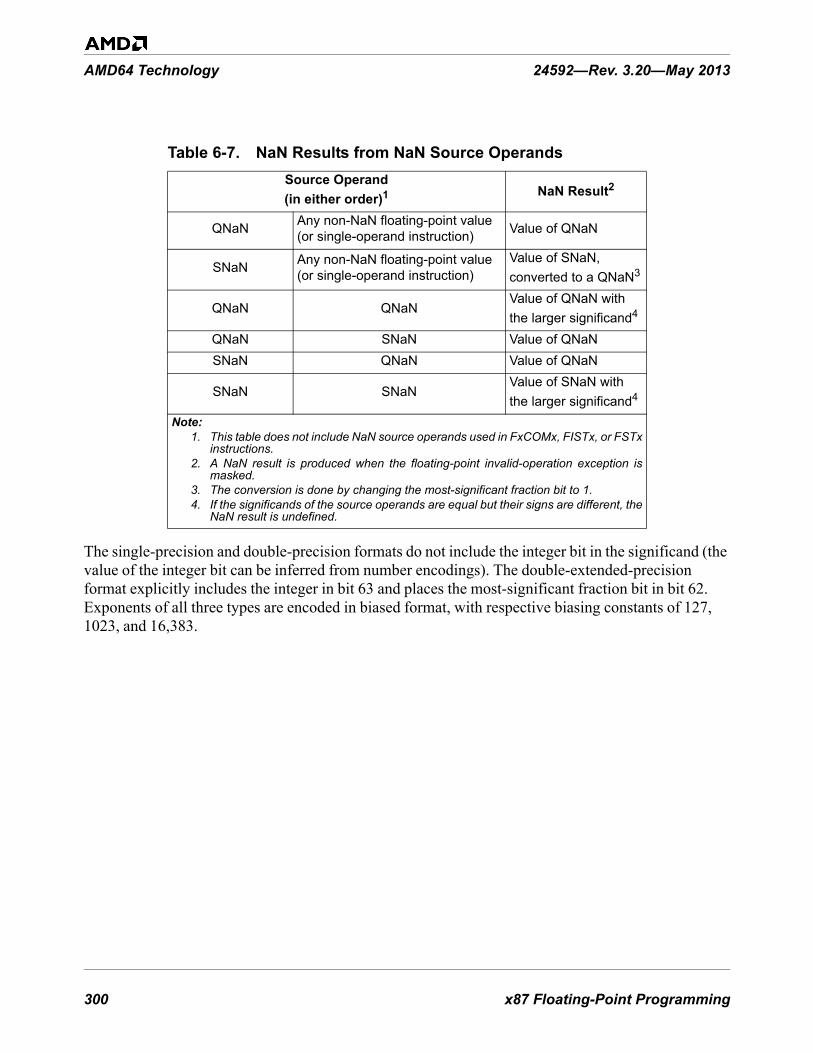
300 x87 Floating-Point Programming
AMD64 Technology 24592—Rev. 3.20—May 2013
The single-precision and double-precision formats do not include the integer bit in the significand (the value of the integer bit can be inferred from number encodings). The double-extended-precision format explicitly includes the integer in bit 63 and places the most-significant fraction bit in bit 62. Exponents of all three types are encoded in biased format, with respective biasing constants of 127, 1023, and 16,383.
Table 6-7. NaN Results from NaN Source OperandsSource Operand(in either order)1 NaN Result2
QNaN Any non-NaN floating-point value (or single-operand instruction) Value of QNaN
SNaN Any non-NaN floating-point value (or single-operand instruction)
Value of SNaN, converted to a QNaN3
QNaN QNaN Value of QNaN with the larger significand4
QNaN SNaN Value of QNaNSNaN QNaN Value of QNaN
SNaN SNaNValue of SNaN with the larger significand4
Note:1. This table does not include NaN source operands used in FxCOMx, FISTx, or FSTx
instructions.2. A NaN result is produced when the floating-point invalid-operation exception is
masked.3. The conversion is done by changing the most-significant fraction bit to 1. 4. If the significands of the source operands are equal but their signs are different, the
NaN result is undefined.

x87 Floating-Point Programming 301
24592—Rev. 3.20—May 2013 AMD64 Technology
Table 6-8. Supported Floating-Point Encodings
Classification Sign Biased
Exponent1 Significand2
Positive Non-Numbers
SNaN 0 111 ... 1111.011 ... 111to1.000 ... 001
QNaN 0 111 ... 1111.111 ... 111to1.100 ... 000
Positive Floating-Point Numbers
Positive Infinity (+∞) 0 111 ... 111 1.000 ... 000
Positive Normal 0111 ... 110to000 ... 001
1.111 ... 111to1.000 ... 000
Positive Pseudo-Denormal3
0 000 ... 0001.111 ... 111to1.000 ... 001
Positive Denormal 0 000 ... 0000.111 ... 111to0.000 ... 001
Positive Zero 0 000 ... 000 0.000 ... 000
Negative Floating-Point Numbers
Negative Zero 1 000 ... 000 0.000 ... 000
Negative Denormal 1 000 ... 0000.000 ... 001to0.111 ... 111
Negative Pseudo-Denormal3
1 000 ... 0001.000 ... 001to1.111 ... 111
Negative Normal 1000 ... 001to111 ... 110
1.000 ... 000to1.111 ... 111
Negative Infinity (-∞) 1 111 ... 111 1.000 ... 000
Negative Non-Numbers
SNaN 1 111 ... 1111.000 ... 001to1.011 ... 111
QNaN4 1 111 ... 1111.100 ... 000to1.111 ... 111
Note:1. The actual exponent field length is 8, 11, or 15 bits, depending on operand preci-
sion.2. The “1.” and “0.” prefixes represent the implicit or explicit integer bit. The actual
fraction field length is 23, 52, or 63 bits, depending on operand precision.3. Pseudo-denormals can only occur in double-extended-precision format, because
they require an explicit integer bit.4. The floating-point indefinite value is a QNaN with a negative sign and a significand
whose value is 1.100 ... 000.

302 x87 Floating-Point Programming
AMD64 Technology 24592—Rev. 3.20—May 2013
6.3.4.2 Unsupported Encodings
Table 6-9 on page 302 shows the encodings of unsupported values. These values can exist only in the double-extended-precision format, because they require an explicit integer bit. The processor does not generate them as results, and they cause an invalid-operation exception (IE) when used as source operands.
6.3.4.3 Indefinite Values
Floating-point, integer, and packed-decimal data types each have a unique encoding that represents an indefinite value. The processor returns an indefinite value when a masked invalid-operation exception (IE) occurs. The indefinite values for various data types are provided in Table 4-7 on page 127.
For example, if a floating-point arithmetic operation is attempted using a source operand which is in an unsupported format, and IE exceptions are masked, the floating-point indefinite value is returned as the result. Or, if an integer store instruction overflows its destination data type, and IE exceptions are masked, the integer indefinite value is returned as the result.
Table 6-10 shows the encodings of the indefinite values for each data type. For floating-point numbers, the indefinite value is a special form of QNaN. For integers, the indefinite value is the largest representable negative two’s-complement number, 80...00h. (This value is interpreted as the largest representable negative number, except when a masked IE exception occurs, in which case it is interpreted as an indefinite value.) For packed-decimal numbers, the indefinite value has no other meaning than indefinite.
Table 6-9. Unsupported Floating-Point Encodings
Classification Sign Biased
Exponent1 Significand2
Positive Pseudo-NaN 0 111 ... 1110.111 ... 111
to0.000 ... 001
Positive Pseudo-Infinity 0 111 ... 111 0.000 ... 000
Positive Unnormal 0111 ... 110
to000 ... 001
0.111 ... 111to
0.000 ... 000
Negative Unnormal 1000 ... 001
to111 ... 110
0.000 ... 000to
0.111 ... 111
Negative Pseudo-Infinity 1 111 ... 111 0.000 ... 000
Negative Pseudo-NaN 1 111 ... 1110.000 ... 001
to0.111 ... 111
Note:1. The actual exponent field length is 15 bits. 2. The “0.” prefix represent the explicit integer bit. The actual fraction field length is 63
bits.

x87 Floating-Point Programming 303
24592—Rev. 3.20—May 2013 AMD64 Technology
6.3.5 Precision
The Precision control (PC) field comprises bits [9:8] of the x87 control word (“x87 Control Word Register (FCW)” on page 286). This field specifies the precision of floating-point calculations for the FADDx, FSUBx, FMULx, FDIVx, and FSQRT instructions, as shown in Table 6-11.
The default precision is double-extended-precision. Selecting double-precision or single-precision reduces the size of the significand to 53 bits or 24 bits, but keeps the exponent in double extended range. The reduced precision is provided to support the IEEE 754 standard. When using reduced precision, rounding clears the unused bits on the right of the significand to 0s.
6.3.6 Rounding
The rounding control (RC) field comprises bits [11:10] of the x87 control word (“x87 Control Word Register (FCW)” on page 286). This field specifies how the results of x87 floating-point computations are rounded. Rounding modes apply to most arithmetic operations but not to comparison or remainder. They have no effect on operations that produce NaN results.
The IEEE 754 standard defines the four rounding modes as shown in Table 6-12.
Table 6-10. Indefinite-Value EncodingsData Type Indefinite Encoding
Single-Precision Floating-Point FFC0_0000hDouble-Precision Floating-Point FFF8_0000_0000_0000hExtended-Precision Floating-Point FFFF_C000_0000_0000_0000h16-Bit Integer 8000h32-Bit Integer 8000_0000h64-Bit Integer 8000_0000_0000_0000h80-Bit BCD FFFF_C000_0000_0000_0000h
Table 6-11. Precision Control Field (PC) Values and Bit PrecisionPC Field Data Type Precision (bits)
00 Single precision 241
01 reserved10 Double precision 531
11 Double-extended precision 64Note:
1. The single-precision and double-precision bit counts include the implied integer bit.
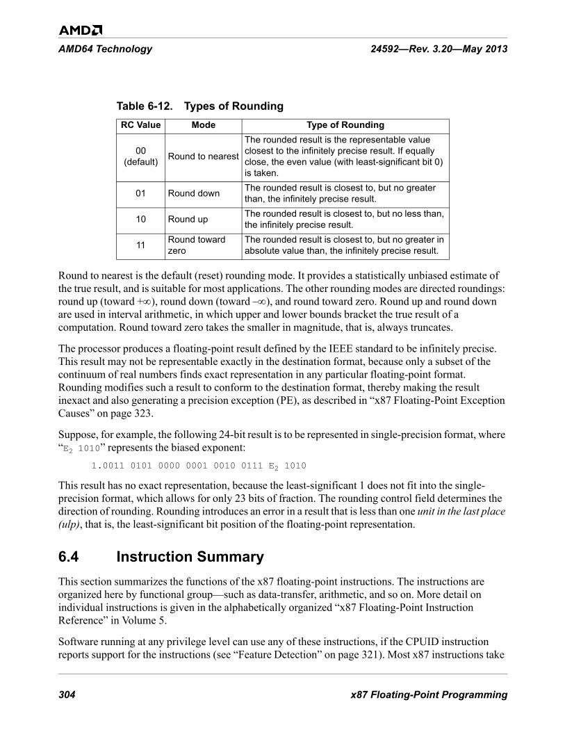
304 x87 Floating-Point Programming
AMD64 Technology 24592—Rev. 3.20—May 2013
Round to nearest is the default (reset) rounding mode. It provides a statistically unbiased estimate of the true result, and is suitable for most applications. The other rounding modes are directed roundings: round up (toward +∞), round down (toward –∞), and round toward zero. Round up and round down are used in interval arithmetic, in which upper and lower bounds bracket the true result of a computation. Round toward zero takes the smaller in magnitude, that is, always truncates.
The processor produces a floating-point result defined by the IEEE standard to be infinitely precise. This result may not be representable exactly in the destination format, because only a subset of the continuum of real numbers finds exact representation in any particular floating-point format. Rounding modifies such a result to conform to the destination format, thereby making the result inexact and also generating a precision exception (PE), as described in “x87 Floating-Point Exception Causes” on page 323.
Suppose, for example, the following 24-bit result is to be represented in single-precision format, where “E2 1010” represents the biased exponent:
1.0011 0101 0000 0001 0010 0111 E2 1010
This result has no exact representation, because the least-significant 1 does not fit into the single-precision format, which allows for only 23 bits of fraction. The rounding control field determines the direction of rounding. Rounding introduces an error in a result that is less than one unit in the last place (ulp), that is, the least-significant bit position of the floating-point representation.
6.4 Instruction SummaryThis section summarizes the functions of the x87 floating-point instructions. The instructions are organized here by functional group—such as data-transfer, arithmetic, and so on. More detail on individual instructions is given in the alphabetically organized “x87 Floating-Point Instruction Reference” in Volume 5.
Software running at any privilege level can use any of these instructions, if the CPUID instruction reports support for the instructions (see “Feature Detection” on page 321). Most x87 instructions take
Table 6-12. Types of RoundingRC Value Mode Type of Rounding
00(default) Round to nearest
The rounded result is the representable value closest to the infinitely precise result. If equally close, the even value (with least-significant bit 0) is taken.
01 Round down The rounded result is closest to, but no greater than, the infinitely precise result.
10 Round up The rounded result is closest to, but no less than, the infinitely precise result.
11 Round toward zero
The rounded result is closest to, but no greater in absolute value than, the infinitely precise result.

x87 Floating-Point Programming 305
24592—Rev. 3.20—May 2013 AMD64 Technology
floating-point data types for both their source and destination operands, although some x87 data-conversion instructions take integer formats for their source or destination operands.
6.4.1 Syntax
Each instruction has a mnemonic syntax used by assemblers to specify the operation and the operands to be used for source and destination (result) data. Many of x87 instructions have the following syntax:
MNEMONIC st(j), st(i)
Figure 6-10 on page 305 shows an example of the mnemonic syntax for a floating-point add (FADD) instruction.
Figure 6-10. Mnemonic Syntax for Typical Instruction
This example shows the FADD mnemonic followed by two operands, both of which are 80-bit stack-register operands. Most instructions take source operands from an x87 stack register and/or memory and write their results to a stack register or memory. Only two of the instructions (FSTSW and FNSTSW) can access a general-purpose registers (GPR), and none access the 128-bit media (XMM) registers. Although the MMX registers map to the x87 registers, the contents of the MMX registers cannot be accessed meaningfully using x87 instructions.
Instructions can have one or more prefixes that modify default operand properties. These prefixes are summarized in “Instruction Prefixes” on page 76.
6.4.1.1 Mnemonics
The following characters are used as prefixes in the mnemonics of integer instructions:
• F—x87 Floating-point
In addition to the above prefix characters, the following characters are used elsewhere in the mnemonics of x87 instructions:
• B—Below, or BCD• BE—Below or Equal
513-146.eps
Mnemonic
First Source Operandand Destination Operand
Second Source Operand
FADD st(0), st(i)

306 x87 Floating-Point Programming
AMD64 Technology 24592—Rev. 3.20—May 2013
• CMOV—Conditional Move• c—Variable condition• E—Equal• I—Integer• LD—Load• N—No Wait• NB—Not Below• NBE—Not Below or Equal• NE—Not Equal• NU—Not Unordered• P—Pop• PP—Pop Twice• R—Reverse• ST—Store• U—Unordered• x—One or more variable characters in the mnemonic
For example, the mnemonic for the store instruction that stores the top-of-stack and pops the stack is FSTP. In this mnemonic, the F means a floating-point instruction, the ST means a store, and the P means pop the stack.
6.4.2 Data Transfer and Conversion
The data transfer and conversion instructions copy data—in some cases with data conversion—between x87 stack registers and memory or between stack positions.
Load or Store Floating-Point• FLD—Floating-Point Load• FST—Floating-Point Store Stack Top• FSTP—Floating-Point Store Stack Top and Pop
The FLD instruction pushes the source operand onto the top-of-stack, ST(0). The source operand may be a single-precision, double-precision, or double-extended-precision floating-point value in memory or the contents of a specified stack position, ST(i).
The FST instruction copies the value at the top-of-stack, ST(0), to a specified stack position, ST(i), or to a 32-bit or 64-bit memory location. If the destination is a memory location, the value copied is converted to the precision allowed by the destination and rounded, as specified by the rounding control (RC) field of the x87 control word. If the top-of-stack value is a NaN or an infinity, FST truncates the stack-top exponent and significand to fit the destination size. (For details, see “FST FSTP” in AMD64

x87 Floating-Point Programming 307
24592—Rev. 3.20—May 2013 AMD64 Technology
Architecture Programmer’s Manual Volume 5: 64-bit Media and x87 Floating-Point Instructions, order# 26569.
The FSTP instruction is similar to FST, except that FSTP can also store to an 80-bit memory location and it pops the stack after the store. FSTP can be used to clean up the x87 stack at the end of an x87 procedure by removing one register of preloaded data from the stack.
Convert and Load or Store Integer• FILD—Floating-Point Load Integer• FIST—Floating-Point Integer Store• FISTP—Floating-Point Integer Store and Pop• FISTTP—Floating-Point Integer Truncate and Store
The FILD instruction converts the 16-bit, 32-bit, or 64-bit source signed integer in memory into a double-extended-precision floating-point value and pushes the result onto the top-of-stack, ST(0).
The FIST instruction converts and rounds the source value in the top-of-stack, ST(0), to a signed integer and copies it to the specified 16-bit or 32-bit memory location. The type of rounding is determined by the rounding control (RC) field of the x87 control word.
The FISTP instruction is similar to FIST, except that FISTP can also store the result to a 64-bit memory location and it pops ST(0) after the store.
The FISTTP instruction converts a floating-point value in ST(0) to an integer by truncating the fractional part of the number and storing the integer result to the memory address specified by the destination operand. FISTTP then pops the floating point register stack. The FISTTP instruction ignores the rounding mode specified by the x87 control word.
Convert and Load or Store BCD• FBLD—Floating-Point Load Binary-Coded Decimal• FBSTP—Floating-Point Store Binary-Coded Decimal Integer and Pop
The FBLD and FBSTP instructions, respectively, push and pop an 80-bit packed BCD memory value on and off the top-of-stack, ST(0). FBLD first converts the value being pushed to a double-extended-precision floating-point value. FBSTP rounds the value being popped to an integer, using the rounding mode specified by the RC field, and converts the value to an 80-bit packed BCD value. Thus, no FRNDIT (round-to-integer) instruction is needed prior to FBSTP.
Conditional Move• FCMOVB—Floating-Point Conditional Move If Below• FCMOVBE—Floating-Point Conditional Move If Below or Equal• FCMOVE—Floating-Point Conditional Move If Equal• FCMOVNB—Floating-Point Conditional Move If Not Below• FCMOVNBE—Floating-Point Conditional Move If Not Below or Equal

308 x87 Floating-Point Programming
AMD64 Technology 24592—Rev. 3.20—May 2013
• FCMOVNE—Floating-Point Conditional Move If Not Equal• FCMOVNU—Floating-Point Conditional Move If Not Unordered• FCMOVU—Floating-Point Conditional Move If Unordered
The FCMOVcc instructions copy the contents of a specified stack position, ST(i), to the top-of-stack, ST(0), if the specified rFLAGS condition is met. Table 6-13 on page 308 specifies the flag combinations for each conditional move.
Exchange• FXCH—Floating-Point Exchange
The FXCH instruction exchanges the contents of a specified stack position, ST(i), with the top-of-stack, ST(0). The top-of-stack pointer is left unchanged. In the form of the instruction that specifies no operand, the contents of ST(1) and ST(0) are exchanged.
Extract• FXTRACT—Floating-Point Extract Exponent and Significand
The FXTRACT instruction copies the unbiased exponent of the original value in the top-of-stack, ST(0), and writes it as a floating-point value to ST(1), then copies the significand and sign of the original value in the top-of-stack and writes it as a floating-point value with an exponent of zero to the top-of-stack, ST(0).
6.4.3 Load Constants
Load 0, 1, or Pi• FLDZ—Floating-Point Load +0.0• FLD1—Floating-Point Load +1.0• FLDPI—Floating-Point Load Pi
Table 6-13. rFLAGS Conditions for FCMOVccCondition Mnemonic rFLAGS Register State
Below B Carry flag is set (CF = 1)
Below or Equal BE Either carry flag or zero flag is set (CF = 1 or ZF = 1)
Equal E Zero flag is set (ZF = 1)Not Below NB Carry flag is not set (CF = 0)
Not Below or Equal NBE Neither carry flag nor zero flag is set (CF = 0, ZF = 0)
Not Equal NE Zero flag is not set (ZF = 0)Not Unordered NU Parity flag is not set (PF = 0)
Unordered U Parity flag is set (PF = 1)

x87 Floating-Point Programming 309
24592—Rev. 3.20—May 2013 AMD64 Technology
The FLDZ, FLD1, and FLDPI instructions, respectively, push the floating-point constant value, +0.0, +1.0, and Pi (3.141592653...), onto the top-of-stack, ST(0).
Load Logarithm• FLDL2E—Floating-Point Load Log2 e• FLDL2T—Floating-Point Load Log2 10• FLDLG2—Floating-Point Load Log10 2• FLDLN2—Floating-Point Load Ln 2
The FLDL2E, FLDL2T, FLDLG2, and FLDLN2 instructions, respectively, push the floating-point constant value, log2e, log210, log102, and loge2, onto the top-of-stack, ST(0).
6.4.4 Arithmetic
The arithmetic instructions support addition, subtraction, multiplication, division, change-sign, round, round to integer, partial remainder, and square root. In most arithmetic operations, one of the source operands is the top-of-stack, ST(0). The other source operand can be another stack entry, ST(i), or a floating-point or integer operand in memory.
The non-commutative operations of subtraction and division have two forms, the direct FSUB and FDIV, and the reverse FSUBR and FDIVR. FSUB, for example, subtracts the right operand from the left operand, and writes the result to the left operand. FSUBR subtracts the left operand from the right operand, and writes the result to the left operand. The FADD and FMUL operations have no reverse counterparts.
Addition• FADD—Floating-Point Add• FADDP—Floating-Point Add and Pop• FIADD—Floating-Point Add Integer to Stack Top
The FADD instruction syntax has forms that include one or two explicit source operands. In the one-operand form, the instruction reads a 32-bit or 64-bit floating-point value from memory, converts it to the double-extended-precision format, adds it to ST(0), and writes the result to ST(0). In the two-operand form, the instruction adds both source operands from stack registers and writes the result to the first operand.
The FADDP instruction syntax has forms that include zero or two explicit source operands. In the zero-operand form, the instruction adds ST(0) to ST(1), writes the result to ST(1), and pops the stack. In the two-operand form, the instruction adds both source operands from stack registers, writes the result to the first operand, and pops the stack.
The FIADD instruction reads a 16-bit or 32-bit integer value from memory, converts it to the double-extended-precision format, adds it to ST(0), and writes the result to ST(0).
Subtraction

310 x87 Floating-Point Programming
AMD64 Technology 24592—Rev. 3.20—May 2013
• FSUB—Floating-Point Subtract• FSUBP—Floating-Point Subtract and Pop• FISUB—Floating-Point Integer Subtract• FSUBR—Floating-Point Subtract Reverse• FSUBRP—Floating-Point Subtract Reverse and Pop• FISUBR—Floating-Point Integer Subtract Reverse
The FSUB instruction syntax has forms that include one or two explicit source operands. In the one-operand form, the instruction reads a 32-bit or 64-bit floating-point value from memory, converts it to the double-extended-precision format, subtracts it from ST(0), and writes the result to ST(0). In the two-operand form, both source operands are located in stack registers. The instruction subtracts the second operand from the first operand and writes the result to the first operand.
The FSUBP instruction syntax has forms that include zero or two explicit source operands. In the zero-operand form, the instruction subtracts ST(0) from ST(1), writes the result to ST(1), and pops the stack. In the two-operand form, both source operands are located in stack registers. The instruction subtracts the second operand from the first operand, writes the result to the first operand, and pops the stack.
The FISUB instruction reads a 16-bit or 32-bit integer value from memory, converts it to the double-extended-precision format, subtracts it from ST(0), and writes the result to ST(0).
The FSUBR and FSUBRP instructions perform the same operations as FSUB and FSUBP, respectively, except that the source operands are reversed. Instead of subtracting the second operand from the first operand, FSUBR and FSUBRP subtract the first operand from the second operand.
Multiplication• FMUL—Floating-Point Multiply• FMULP—Floating-Point Multiply and Pop• FIMUL—Floating-Point Integer Multiply
The FMUL instruction has three forms. One form of the instruction multiplies two double-extended precision floating-point values located in ST(0) and another floating-point stack register and leaves the product in ST(0). The second form multiplies two double-extended precision floating-point values located in ST(0) and another floating-point stack destination register and leaves the product in the destination register. The third form converts a floating-point value in a specified memory location to double-extended-precision format, multiplies the result by the value in ST(0) and writes the product to ST(0).
The FMULP instruction syntax is similar to the form of FMUL described in the previous paragraph. This instruction pops the floating-point register stack after performing the multiplication operation. This instruction cannot take a memory operand.

x87 Floating-Point Programming 311
24592—Rev. 3.20—May 2013 AMD64 Technology
The FIMUL instruction reads a 16-bit or 32-bit integer value from memory, converts it to the double-extended-precision format, multiplies ST(0) by the memory operand, and writes the result to ST(0).
Division• FDIV—Floating-Point Divide• FDIVP—Floating-Point Divide and Pop• FIDIV—Floating-Point Integer Divide• FDIVR—Floating-Point Divide Reverse• FDIVRP—Floating-Point Divide Reverse and Pop• FIDIVR—Floating-Point Integer Divide Reverse
The FDIV instruction syntax has forms that include one or two source explicit operands that may be single-precision or double-precision floating-point values or 16-bit or 32-bit integer values. In the one-operand form, the instruction reads a value from memory, divides ST(0) by the memory operand, and writes the result to ST(0). In the two-operand form, both source operands are located in stack registers. The instruction divides the first operand by the second operand and writes the result to the first operand.
The FDIVP instruction syntax has forms that include zero or two explicit source operands. In the zero-operand form, the instruction divides ST(1) by ST(0), writes the result to ST(1), and pops the stack. In the two-operand form, both source operands are located in stack registers. The instruction divides the first operand by the second operand, writes the result to the first operand, and pops the stack.
The FIDIV instruction reads a 16-bit or 32-bit integer value from memory, converts it to the double-extended-precision format, divides ST(0) by the memory operand, and writes the result to ST(0).
The FDIVR and FDIVRP instructions perform the same operations as FDIV and FDIVP, respectively, except that the source operands are reversed. Instead of dividing the first operand by the second operand, FDIVR and FDIVRP divide the second operand by the first operand.
Change Sign• FABS—Floating-Point Absolute Value• FCHS—Floating-Point Change Sign
The FABS instruction changes the top-of-stack value, ST(0), to its absolute value by clearing its sign bit to 0. The top-of-stack value is always positive following execution of the FABS instruction. The FCHS instruction complements the sign bit of ST(0). For example, if ST(0) was +0.0 before the execution of FCHS, it is changed to -0.0.
Round• FRNDINT—Floating-Point Round to Integer

312 x87 Floating-Point Programming
AMD64 Technology 24592—Rev. 3.20—May 2013
The FRNDINT instruction rounds the top-of-stack value, ST(0), to an integer value, although the value remains in double-extended-precision floating-point format. Rounding takes place according to the setting of the rounding control (RC) field in the x87 control word.
Partial Remainder• FPREM—Floating-Point Partial Remainder• FPREM1—Floating-Point Partial Remainder
The FPREM instruction returns the remainder obtained by dividing ST(0) by ST(1) and stores it in ST(0). If the exponent difference between ST(0) and ST(1) is less than 64, all integer bits of the quotient are calculated, guaranteeing that the remainder returned is less in magnitude than the divisor in ST(1). If the exponent difference is equal to or greater than 64, only a subset of the integer quotient bits, numbering between 32 and 63, are calculated and a partial remainder is returned. FPREM can be repeated on a partial remainder until reduction is complete. It can be used to bring the operands of transcendental functions into their proper range. FPREM is supported for software written for early x87 coprocessors. Unlike the FPREM1 instruction, FPREM does not calculate the partial remainder as specified in IEEE Standard 754.
The FPREM1 instruction works like FPREM, except that the FPREM1 quotient is rounded using round-to-nearest mode, whereas FPREM truncates the quotient.
Square Root• FSQRT—Floating-Point Square Root
The FSQRT instruction replaces the contents of the top-of-stack, ST(0), with its square root.
6.4.5 Transcendental Functions
The transcendental instructions compute trigonometric functions, inverse trigonometric functions, logarithmic functions, and exponential functions.
Trigonometric Functions• FSIN—Floating-Point Sine• FCOS—Floating-Point Cosine• FSINCOS—Floating-Point Sine and Cosine• FPTAN—Floating-Point Partial Tangent• FPATAN—Floating-Point Partial Arctangent
The FSIN instruction replaces the contents of ST(0) (in radians) with its sine.
The FCOS instruction replaces the contents of ST(0) (in radians) with its cosine.
The FSINCOS instruction computes both the sine and cosine of the contents of ST(0) (in radians) and writes the sine to ST(0) and pushes the cosine onto the stack. Frequently, a piece of code that needs to compute the sine of an argument also needs to compute the cosine of that same argument. In such

x87 Floating-Point Programming 313
24592—Rev. 3.20—May 2013 AMD64 Technology
cases, use the FSINCOS instruction to compute both functions concurrently, which is faster than using separate FSIN and FCOS instructions.
The FPTAN instruction replaces the contents of the ST(0) (in radians), with its tangent, in radians, and pushes the value 1.0 onto the stack.
The FPATAN instruction computes θ = arctan (Y/X), in which X is located in ST(0) and Y in ST(1). The result, θ, is written over Y in ST(1), and the stack is popped.
FSIN, FCOS, FSINCOS, and FPTAN are architecturally restricted in their argument range. Only arguments with a magnitude of less than 263 can be evaluated. If the argument is out of range, the C2 condition-code bit in the x87 status word is set to 1, and the argument is returned as the result. If software detects an out-of-range argument, the FPREM or FPREM1 instruction can be used to reduce the magnitude of the argument before using the FSIN, FCOS, FSINCOS, or FPTAN instruction again.
Logarithmic Functions• F2XM1—Floating-Point Compute 2x–1• FSCALE—Floating-Point Scale• FYL2X—Floating-Point y * log2x• FYL2XP1—Floating-Point y * log2(x +1)
The F2XM1 instruction computes Y = 2X – 1. X is located in ST(0) and must fall between –1 and +1. Y replaces X in ST(0). If ST(0) is out of range, the instruction returns an undefined result but no x87 status-word exception bits are affected.
The FSCALE instruction replaces ST(0) with ST(0) times 2n, where n is the value in ST(1) truncated to an integer. This provides a fast method of multiplying by integral powers of 2.
The FYL2X instruction computes Z = Y * log2 X. X is located in ST(0) and Y is located in ST(1). X must be greater than 0. The result, Z, replaces Y in ST(1), which becomes the new top-of-stack because X is popped off the stack.
The FYL2XP1 instruction computes Z = Y * log2(X + 1). X located in ST(0) and must be in the range 0 < |X| < (1 – 2½ / 2). Y is taken from ST(1). The result, Z, replaces Y in ST(1), which becomes the new top-of-stack because X is popped off the stack.
6.4.5.1 Accuracy of Transcendental Results
x87 computations are carried out in double-extended-precision format, so that the transcendental functions provide results accurate to within one unit in the last place (ulp) for each of the floating-point data types.
6.4.5.2 Argument Reduction Using Pi
The FPREM and FPREM1 instructions can be used to reduce an argument of a trigonometric function by a multiple of Pi. The following example shows a reduction by 2π:

314 x87 Floating-Point Programming
AMD64 Technology 24592—Rev. 3.20—May 2013
sin(n*2π + x) = sin(x) for all integral n
In this example, the range is 0 ≤ x < 2π in the case of FPREM or -π ≤ x ≤ π in the case of FPREM1. Negative arguments are reduced by repeatedly subtracting –2π. See “Partial Remainder” on page 312 for details of the instructions.
6.4.6 Compare and Test
The compare-and-test instructions set and clear flags in the rFLAGS register to indicate the relationship between two operands (less, equal, greater, or unordered).
Floating-Point Ordered Compare• FCOM—Floating-Point Compare• FCOMP—Floating-Point Compare and Pop• FCOMPP—Floating-Point Compare and Pop Twice• FCOMI—Floating-Point Compare and Set Flags• FCOMIP—Floating-Point Compare and Set Flags and Pop
The FCOM instruction syntax has forms that include zero or one explicit source operands. In the zero-operand form, the instruction compares ST(1) with ST(0) and writes the x87 status-word condition codes accordingly. In the one-operand form, the instruction reads a 32-bit or 64-bit value from memory, compares it with ST(0), and writes the x87 condition codes accordingly.
The FCOMP instruction performs the same operation as FCOM but also pops ST(0) after writing the condition codes.
The FCOMPP instruction performs the same operation as FCOM but also pops both ST(0) and ST(1). FCOMPP can be used to initialize the x87 stack at the end of an x87 procedure by removing two registers of preloaded data from the stack.
The FCOMI instruction compares the contents of ST(0) with the contents of another stack register and writes the ZF, PF, and CF flags in the rFLAGS register as shown in Table 6-14. If no source is specified, ST(0) is compared to ST(1). If ST(0) or the source operand is a NaN or in an unsupported format, the flags are set to indicate an unordered condition.
The FCOMIP instruction performs the same comparison as FCOMI but also pops ST(0) after writing the rFLAGS bits.
Table 6-14. rFLAGS Values for FCOMI InstructionFlag ST(0) > ST(i) ST(0) < ST(i) ST(0) = ST(i) UnorderedZF 0 0 1 1PF 0 0 0 1CF 0 1 0 1

x87 Floating-Point Programming 315
24592—Rev. 3.20—May 2013 AMD64 Technology
For comparison-based branches, the combination of FCOMI and FCMOVcc is faster than the classical method of using FxSTSW AX to copy condition codes through the AX register to the rFLAGS register, where they can provide branch direction for conditional operations.
The FCOMx instructions perform ordered compares, as opposed to the FUCOMx instructions. See the description of ordered vs. unordered compares immediately below.
Floating-Point Unordered Compare• FUCOM—Floating-Point Unordered Compare• FUCOMP—Floating-Point Unordered Compare and Pop• FUCOMPP—Floating-Point Unordered Compare and Pop Twice• FUCOMI—Floating-Point Unordered Compare and Set Flags• FUCOMIP—Floating-Point Unordered Compare and Set Flags and Pop
The FUCOMx instructions perform the same operations as the FCOMx instructions, except that the FUCOMx instructions generate an invalid-operation exception (IE) only if any operand is an unsupported data type or a signaling NaN (SNaN), whereas the ordered-compare FCOMx instructions generate an invalid-operation exception if any operand is an unsupported data type or any type of NaN. For a description of NaNs, see “Number Representation” on page 296.
Integer Compare• FICOM—Floating-Point Integer Compare• FICOMP—Floating-Point Integer Compare and Pop
The FICOM instruction reads a 16-bit or 32-bit integer value from memory, compares it with ST(0), and writes the condition codes in the same way as the FCOM instruction.
The FICOMP instruction performs the same operations as FICOM but also pops ST(0).
Test• FTST—Floating-Point Test with Zero
The FTST instruction compares ST(0) with zero and writes the condition codes in the same way as the FCOM instruction.
Classify• FXAM—Floating-Point Examine
The FXAM instruction determines the type of value in ST(0) and sets the condition codes accordingly, as shown in Table 6-15.
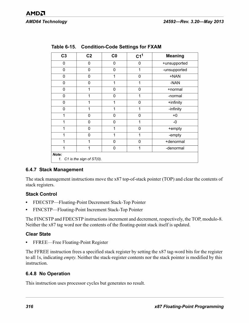
316 x87 Floating-Point Programming
AMD64 Technology 24592—Rev. 3.20—May 2013
6.4.7 Stack Management
The stack management instructions move the x87 top-of-stack pointer (TOP) and clear the contents of stack registers.
Stack Control• FDECSTP—Floating-Point Decrement Stack-Top Pointer• FINCSTP—Floating-Point Increment Stack-Top Pointer
The FINCSTP and FDECSTP instructions increment and decrement, respectively, the TOP, modulo-8. Neither the x87 tag word nor the contents of the floating-point stack itself is updated.
Clear State• FFREE—Free Floating-Point Register
The FFREE instruction frees a specified stack register by setting the x87 tag-word bits for the register to all 1s, indicating empty. Neither the stack-register contents nor the stack pointer is modified by this instruction.
6.4.8 No Operation
This instruction uses processor cycles but generates no result.
Table 6-15. Condition-Code Settings for FXAM
C3 C2 C0 C11 Meaning0 0 0 0 +unsupported0 0 0 1 -unsupported0 0 1 0 +NAN0 0 1 1 -NAN0 1 0 0 +normal0 1 0 1 -normal0 1 1 0 +infinity0 1 1 1 -infinity1 0 0 0 +01 0 0 1 -01 0 1 0 +empty1 0 1 1 -empty1 1 0 0 +denormal1 1 0 1 -denormal
Note:1. C1 is the sign of ST(0).

x87 Floating-Point Programming 317
24592—Rev. 3.20—May 2013 AMD64 Technology
• FNOP—Floating-Point No Operation
The FNOP instruction has no operands and writes no result. Its purpose is simply to delay execution of a sequence of instructions.
6.4.9 Control
The control instructions are used to initialize, save, and restore x87 processor state and to manage x87 exceptions.
Initialize• FINIT—Floating-Point Initialize• FNINIT—Floating-Point No-Wait Initialize
The FINIT and FNINIT instructions set all bits in the x87 control-word, status-word, and tag word registers to their default values. Assemblers issue FINIT as an FWAIT instruction followed by an FNINIT instruction. Thus, FINIT (but not FNINIT) reports pending unmasked x87 floating-point exceptions before performing the initialization.
Both FINIT and FNINIT write the control word with its initialization value, 037Fh, which specifies round-to-nearest, all exceptions masked, and double-extended-precision. The tag word indicates that the floating-point registers are empty. The status word and the four condition-code bits are cleared to 0. The x87 pointers and opcode state (“Pointers and Opcode State” on page 289) are all cleared to 0.
The FINIT instruction should be used when pending x87 floating-point exceptions are being reported (unmasked). The no-wait instruction, FNINIT, should be used when pending x87 floating-point exceptions are not being reported (masked).
Wait for Exceptions• FWAIT or WAIT—Wait for Unmasked x87 Floating-Point Exceptions
The FWAIT and WAIT instructions are synonyms. The instruction forces the processor to test for and handle any pending, unmasked x87 floating-point exceptions.
Clear Exceptions• FCLEX—Floating-Point Clear Flags• FNCLEX—Floating-Point No-Wait Clear Flags
These instructions clear the status-word exception flags, stack-fault flag, and busy flag. They leave the four condition-code bits undefined.
Assemblers issue FCLEX as an FWAIT instruction followed by an FNCLEX instruction. Thus, FCLEX (but not FNCLEX) reports pending unmasked x87 floating-point exceptions before clearing the exception flags.

318 x87 Floating-Point Programming
AMD64 Technology 24592—Rev. 3.20—May 2013
The FCLEX instruction should be used when pending x87 floating-point exceptions are being reported (unmasked). The no-wait instruction, FNCLEX, should be used when pending x87 floating-point exceptions are not being reported (masked).
Save and Restore x87 Control Word• FLDCW—Floating-Point Load x87 Control Word• FSTCW—Floating-Point Store Control Word• FNSTCW—Floating-Point No-Wait Store Control Word
These instructions load or store the x87 control-word register as a 2-byte value from or to a memory location.
The FLDCW instruction loads a control word. If the loaded control word unmasks any pending x87 floating-point exceptions, these exceptions are reported when the next non-control x87 or 64-bit media instruction is executed.
Assemblers issue FSTCW as an FWAIT instruction followed by an FNSTCW instruction. Thus, FSTCW (but not FNSTCW) reports pending unmasked x87 floating-point exceptions before storing the control word.
The FSTCW instruction should be used when pending x87 floating-point exceptions are being reported (unmasked). The no-wait instruction, FNSTCW, should be used when pending x87 floating-point exceptions are not being reported (masked).
Save x87 Status Word• FSTSW—Floating-Point Store Status Word• FNSTSW—Floating-Point No-Wait Store Status Word
These instructions store the x87 status word either at a specified 2-byte memory location or in the AX register. The second form, FxSTSW AX, is used in older code to copy condition codes through the AX register to the rFLAGS register, where they can be used for conditional branching using general-purpose instructions. However, the combination of FCOMI and FCMOVcc provides a faster method of conditional branching.
Assemblers issue FSTSW as an FWAIT instruction followed by an FNSTSW instruction. Thus, FSTSW (but not FNSTSW) reports pending unmasked x87 floating-point exceptions before storing the status word.
The FSTSW instruction should be used when pending x87 floating-point exceptions are being reported (unmasked). The no-wait instruction, FNSTSW, should be used when pending x87 floating-point exceptions are not being reported (masked).
Save and Restore x87 Environment• FLDENV—Floating-Point Load x87 Environment• FNSTENV—Floating-Point No-Wait Store Environment

x87 Floating-Point Programming 319
24592—Rev. 3.20—May 2013 AMD64 Technology
• FSTENV—Floating-Point Store Environment
These instructions load or store the entire x87 environment (non-data processor state) as a 14-byte or 28-byte block, depending on effective operand size, from or to memory.
When executing FLDENV, any exception flags are set in the new status word, and these exceptions are unmasked in the control word, a floating-point exception occurs when the next non-control x87 or 64-bit media instruction is executed.
Assemblers issue FSTENV as an FWAIT instruction followed by an FNSTENV instruction. Thus, FSTENV (but not FNSTENV) reports pending unmasked x87 floating-point exceptions before storing the status word.
The x87 environment includes the x87 control word register, x87 status word register, x87 tag word, last x87 instruction pointer, last x87 data pointer, and last x87 opcode. See “Media and x87 Processor State” in Volume 2 for details on how the x87 environment is stored in memory.
Save and Restore x87 and 64-Bit Media State• FSAVE—Save x87 and MMX State.• FNSAVE—Save No-Wait x87 and MMX State.• FRSTOR—Restore x87 and MMX State.
These instructions save and restore the entire processor state for x87 floating-point instructions and 64-bit media instructions. The instructions save and restore either 94 or 108 bytes of data, depending on the effective operand size.
Assemblers issue FSAVE as an FWAIT instruction followed by an FNSAVE instruction. Thus, FSAVE (but not FNSAVE) reports pending unmasked x87 floating-point exceptions before saving the state.
After saving the state, the processor initializes the x87 state by performing the equivalent of an FINIT instruction. For details, see “State-Saving” on page 334.
Save and Restore x87, 128-Bit, and 64-Bit State• FXSAVE—Save XMM, MMX, and x87 State.• FXRSTOR—Restore XMM, MMX, and x87 State.
The FXSAVE and FXRSTOR instructions save and restore the entire 512-byte processor state for 128-bit media instructions, 64-bit media instructions, and x87 floating-point instructions. The architecture supports two memory formats for FXSAVE and FXRSTOR, a 512-byte 32-bit legacy format and a 512-byte 64-bit format. Selection of the 32-bit or 64-bit format is determined by the effective operand size for the FXSAVE and FXRSTOR instructions. For details, see “Media and x87 Processor State” in Volume 2.
FXSAVE and FXRSTOR execute faster than FSAVE/FNSAVE and FRSTOR. However, unlike FSAVE and FNSAVE, FXSAVE does not initialize the x87 state, and like FNSAVE it does not report pending unmasked x87 floating-point exceptions. For details, see “State-Saving” on page 334.

320 x87 Floating-Point Programming
AMD64 Technology 24592—Rev. 3.20—May 2013
6.5 Instruction Effects on rFLAGSThe rFLAGS register is described in “Flags Register” on page 34. Table 6-16 on page 320 summarizes the effect that x87 floating-point instructions have on individual flags within the rFLAGS register. Only instructions that access the rFLAGS register are shown—all other x87 instructions have no effect on rFLAGS.
The following codes are used within the table:
• Mod—The flag is modified.• Tst—The flag is tested.• Gray shaded cells indicate the flag is not affected by the instruction.
6.6 Instruction PrefixesInstruction prefixes, in general, are described in “Instruction Prefixes” on page 76. The following restrictions apply to the use of instruction prefixes with x87 instructions.
6.6.0.1 Supported Prefixes
The following prefixes can be used with x87 instructions:
• Operand-Size Override—The 66h prefix affects only the FLDENV, FSTENV, FNSTENV, FSAVE, FNSAVE, and FRSTOR instructions, in which it selects between a 16-bit and 32-bit memory-image format. The prefix is ignored by all other x87 instructions.
• Address-Size Override—The 67h prefix affects only operands in memory, in which it selects between a 16-bit and 32-bit addresses. The prefix is ignored by all other x87 instructions.
• Segment Overrides—The 2Eh (CS), 36h (SS), 3Eh (DS), 26h (ES), 64h (FS), and 65h (GS) prefixes specify a segment. They affect only operands in memory. In 64-bit mode, the CS, DS, ES, SS segment overrides are ignored.
• REX—The REX.W bit affects the FXSAVE and FXRSTOR instructions, in which it selects between two types of 512-byte memory-image formats, as described in "Saving Media and x87 Processor State" in Volume 2. The REX.W bit also affects the FLDENV, FSTENV, FSAVE, and
Table 6-16. Instruction Effects on rFLAGS
Instruction Mnemonic
rFLAGS Mnemonic and Bit NumberOF11
SF7
ZF6
AF4
PF2
CF0
FCMOVcc Tst Tst TstFCOMI
FCOMIPFUCOMI
FUCOMIP
Mod Mod Mod

x87 Floating-Point Programming 321
24592—Rev. 3.20—May 2013 AMD64 Technology
FRSTOR instructions, in which it selects the 32-bit memory-image format. The REX.R, REX.X, and REX.B bits only affect operands in memory, in which they are used to find the memory operand.
6.6.0.2 Ignored Prefixes
The following prefixes are ignored by x87 instructions:
• REP—The F3h and F2h prefixes.
6.6.0.3 Prefixes That Cause Exceptions
The following prefixes cause an exception:
• LOCK—The F0h prefix causes an invalid-opcode exception when used with x87 instructions.
6.7 Feature DetectionBefore executing x87 floating-point instructions, software should determine if the processor supports the technology by executing the CPUID instruction. “Feature Detection” on page 79 describes how software uses the CPUID instruction to detect feature support. For full support of the x87 floating-point features, the following feature must be present:
• On-Chip Floating-Point Unit, indicated by bit 0 of CPUID function 1 and CPUID function 8000_0001h.
• CMOVcc (conditional moves), indicated by bit 15 of CPUID function 1 and CPUID function 8000_0001h. This bit indicates support for x87 floating-point conditional moves (FCMOVcc) whenever the On-Chip Floating-Point Unit bit (bit 0) is also set.
Software may also wish to check for the following support, because the FXSAVE and FXRSTOR instructions execute faster than FSAVE and FRSTOR:
• FXSAVE and FXRSTOR, indicated by bit 24 of CPUID function 1 and function 8000_0001h.
Software that runs in long mode should also check for the following support:
• Long Mode, indicated by bit 29 of CPUID function 8000_0001h.
See “CPUID” in Volume 3 for details on the CPUID instruction and Appendix D of that volume for information on detemining support for specific instruction subsets.
6.8 Exceptions
6.8.0.1 Types of Exceptions
x87 instructions can generate two types of exceptions:
• General-Purpose Exceptions, described below in “General-Purpose Exceptions”

322 x87 Floating-Point Programming
AMD64 Technology 24592—Rev. 3.20—May 2013
• x87 Floating-Point Exceptions (#MF), described in “x87 Floating-Point Exception Causes” on page 323
6.8.0.2 Relation to 128-Bit Media Exceptions
Although the x87 floating-point instructions and the 128-bit media instructions each have certain exceptions with the same names, the exception-reporting and exception-handling methods used by the two instruction subsets are distinct and independent of each other. If procedures using both types of instructions are run in the same operating environment, separate service routines should be provided for the exceptions of each type of instruction subset.
6.8.1 General-Purpose Exceptions
The sections below list general-purpose exceptions generated and not generated by x87 floating-point instructions. For a summary of the general-purpose exception mechanism, see “Interrupts and Exceptions” on page 90. For details about each exception and its potential causes, see “Exceptions and Interrupts” in Volume 2.
6.8.1.1 Exceptions Generated
x87 instructions can generate the following general-purpose exceptions:
• #DB—Debug Exception (Vector 1)• #BP—Breakpoint Exception (Vector 3)• #UD—Invalid-Opcode Exception (Vector 6)• #NM—Device-Not-Available Exception (Vector 7)• #DF—Double-Fault Exception (Vector 8)• #SS—Stack Exception (Vector 12)• #GP—General-Protection Exception (Vector 13)• #PF—Page-Fault Exception (Vector 14)• #MF—x87 Floating-Point Exception-Pending (Vector 16)• #AC—Alignment-Check Exception (Vector 17)• #MC—Machine-Check Exception (Vector 18)
For details on #MF exceptions, see “x87 Floating-Point Exception Causes” below.
6.8.1.2 Exceptions Not Generated
x87 instructions do not generate the following general-purpose exceptions:
• #DE—Divide-by-zero-error exception (Vector 0)• Non-Maskable-Interrupt Exception (Vector 2)• #OF—Overflow exception (Vector 4)• #BR—Bound-range exception (Vector 5)

x87 Floating-Point Programming 323
24592—Rev. 3.20—May 2013 AMD64 Technology
• Coprocessor-segment-overrun exception (Vector 9)• #TS—Invalid-TSS exception (Vector 10)• #NP—Segment-not-present exception (Vector 11)• #MC—Machine-check exception (Vector 18)• #XF—SIMD floating-point exception (Vector 19)
For details on all general-purpose exceptions, see “Exceptions and Interrupts” in Volume 2.
6.8.2 x87 Floating-Point Exception Causes
The x87 floating-point exception-pending (#MF) exception listed above in “General-Purpose Exceptions” is actually the logical OR of six exceptions that can be caused by x87 floating-point instructions. Each of the six exceptions has a status flag in the x87 status word and a mask bit in the x87 control word. A seventh exception, stack fault (SF), is reported together with one of the six maskable exceptions and does not have a mask bit.
If a #MF exception occurs when its mask bit is set to 1 (masked), the processor responds in a default way that does not invoke the #MF exception service routine. If an exception occurs when its mask bit is cleared to 0 (unmasked), the processor suspends processing of the faulting instruction (if possible) and, at the boundary of the next non-control x87 or 64-bit media instruction (see “Control” on page 317), determines that an unmasked exception is pending—by checking the exception status (ES) flag in the x87 status word—and invokes the #MF exception service routine.
6.8.2.1 #MF Exception Types and Flags
The #MF exceptions are of six types, five of which are mandated by the IEEE 754 standard. These six types and their bit-flags in the x87 status word are shown in Table 6-17. A stack fault (SF) exception is always accompanied by an invalid-operation exception (IE). A summary of each exception type is given in “x87 Status Word Register (FSW)” on page 283.
Table 6-17. x87 Floating-Point (#MF) Exception Flags
Exception and Mnemonicx87 Status-Word Bit1
Comparable IEEE 754 Exception
Invalid-operation exception (IE) 0 Invalid OperationInvalid-operation exception (IE) with stack fault (SF) exception 0 and 6 none
Denormalized-operand exception (DE) 1 noneZero-divide exception (ZE) 2 Division by ZeroOverflow exception (OE) 3 OverflowUnderflow exception (UE) 4 UnderflowPrecision exception (PE) 5 InexactNote:
1. See “x87 Status Word Register (FSW)” on page 283 for a summary of each exception.

324 x87 Floating-Point Programming
AMD64 Technology 24592—Rev. 3.20—May 2013
The sections below describe the causes for the #MF exceptions. Masked and unmasked responses to the exceptions are described in “x87 Floating-Point Exception Masking” on page 327. The priority of #MF exceptions are described in “x87 Floating-Point Exception Priority” on page 326.
6.8.2.2 Invalid-Operation Exception (IE)
The IE exception occurs due to one of the attempted operations shown in Table 6-18 on page 325. An IE exception may also be accompanied by a stack fault (SF) exception. See “Stack Fault (SF)” on page 326.
6.8.2.3 Denormalized-Operand Exception (DE)
The DE exception occurs in any of the following cases:
Table 6-18. Invalid-Operation Exception (IE) CausesOperation Condition
Arithmetic (IE exception)
Any Arithmetic Operation• A source operand is an SNaN, or• A source operand is an unsupported data type (pseudo-
NaN, pseudo-infinity, or unnormal).FADD, FADDP Source operands are infinities with opposite signs.FSUB, FSUBP, FSUBR, FSUBRP Source operands are infinities with same sign.
FMUL, FMULP Source operands are zero and infinity.FDIV, FDIVP, FDIVR, FDIVRP Source operands are both infinities or both zeros.
FSQRT Source operand is less than zero (except ±0 which returns ±0).
FYL2XSource operand is less than zero (except ±0 which returns ±∞).
FYL2XP1 Source operand is less than minus one.FCOS, FPTAN, FSIN, FSINCOS Source operand is infinity.
FCOM, FCOMP, FCOMPP, FCOMI, FCOMIP
A source operand is a QNaN.
FPREM, FPREM1 Dividend is infinity or divisor is zero.FIST, FISTP, FISTTP Source operand overflows the destination size.FBSTP Source operand overflows packed BCD data size.
Stack(IE and SF exceptions) Stack overflow or underflow.1
Note:1. The processor sets condition code C1 = 1 for overflow, C1 = 0 for underflow.

x87 Floating-Point Programming 325
24592—Rev. 3.20—May 2013 AMD64 Technology
• Denormalized Operand (any precision)—An arithmetic instruction uses an operand of any precision that is in denormalized form, as described in “Denormalized (Tiny) Numbers” on page 297.
• Denormalized Single-Precision or Double-Precision Load—An instruction loads a single-precision or double-precision (but not double-extended-precision) operand, which is in denormalized form, into an x87 register.
6.8.2.4 Zero-Divide Exception (ZE)
The ZE exception occurs when:
• Divisor is Zero—An FDIV, FDIVP, FDIVR, FDIVRP, FIDIV, or FIDIVR instruction attempts to divide zero into a non-zero finite dividend.
• Source Operand is Zero—An FYL2X or FXTRACT instruction uses a source operand that is zero.
6.8.2.5 Overflow Exception (OE)
The OE exception occurs when the value of a rounded floating-point result is larger than the largest representable normalized positive or negative floating-point number in the destination format, as shown in Table 6-5 on page 295. An overflow can occur through computation or through conversion of higher-precision numbers to lower-precision numbers. See “Precision” on page 303. Integer and BCD overflow is reported via the invalid-operation exception.
6.8.2.6 Underflow Exception (UE)
The UE exception occurs when the value of a rounded, non-zero floating-point result is too small to be represented as a normalized positive or negative floating-point number in the destination format, as shown in Table 6-5 on page 295. Integer and BCD underflow is reported via the invalid-operation exception.
6.8.2.7 Precision Exception (PE)
The PE exception, also called the inexact-result exception, occurs when a floating-point result, after rounding, differs from the infinitely precise result and thus cannot be represented exactly in the specified destination format. Software that does not require exact results normally masks this exception. See “Precision” on page 303 and “Rounding” on page 303.
6.8.2.8 Stack Fault (SF)
The SF exception occurs when a stack overflow (due to a push or load into a non-empty stack register) or stack underflow (due to referencing an empty stack register) occurs in the x87 stack-register file. The empty and non-empty conditions are shown in Table 6-3 on page 289. When either of these conditions occur, the processor also sets the invalid-operation exception (IE) flag, and it sets or clears the condition-code 1 (C1) bit to indicate the direction of the stack fault (C1 = 1 for overflow, C1 = 0 for underflow). Unlike the flags for the other x87 exceptions, the SF flag does not have a corresponding mask bit in the x87 control word.

326 x87 Floating-Point Programming
AMD64 Technology 24592—Rev. 3.20—May 2013
6.8.3 x87 Floating-Point Exception Priority
Table 6-19 shows the priority with which the processor recognizes multiple, simultaneous SIMD floating-point exceptions and operations involving QNaN operands. Each exception type is characterized by its timing, as follows:
• Pre-Computation—an exception that is recognized before an instruction begins its operation.• Post-Computation—an exception that is recognized after an instruction completes its operation.
For post-computation exceptions, a result may be written to the destination, depending on the type of exception and whether the destination is a register or memory location. Operations involving QNaNs do not necessarily cause exceptions, but the processor handles them with the priority shown in Table 6-19 on page 327 relative to the handling of exceptions.
For exceptions that occur before the associated operation (pre-operation, as shown in Table 6-19), if an unmasked exception occurs, the processor suspends processing of the faulting instruction but it waits until the boundary of the next non-control x87 or 64-bit media instruction to be executed before invoking the associated exception service routine. During this delay, non-x87 instructions may overwrite the faulting x87 instruction’s source or destination operands in memory. If that occurs, the x87 service routine may be unable to perform its job.
Table 6-19. Priority of x87 Floating-Point ExceptionsPriority Exception or Operation Timing
1 Invalid-operation exception (IE) with stack fault (SF) due to underflow Pre-Computation
2 Invalid-operation exception (IE) with stack fault (SF) due to overflow Pre-Computation
3 Invalid-operation exception (IE) when accessing unsupported data type Pre-Computation
4 Invalid-operation exception (IE) when accessing SNaN operand Pre-Computation
5 Operation involving a QNaN operand1 —
6Any other type of invalid-operation exception (IE) Pre-Computation
Zero-divide exception (ZE) Pre-Computation
7 Denormalized operation exception (DE) Pre-Computation
8Overflow exception (OE) Post-Computation
Underflow exception (UE) Post-Computation
9 Precision (inexact) exception (PE) Post-ComputationNote:
1. Operations involving QNaN operands do not, in themselves, cause exceptions but they arehandled with this priority relative to the handling of exceptions.

x87 Floating-Point Programming 327
24592—Rev. 3.20—May 2013 AMD64 Technology
To prevent such problems, analyze x87 procedures for potential exception-causing situations and insert a WAIT or other safe x87 instruction immediately after any x87 instruction that may cause a problem.
6.8.4 x87 Floating-Point Exception Masking
The six floating-point exception flags in the x87 status word have corresponding exception-flag masks in the x87 control word, as shown in Table 6-20 on page 328.
Each mask bit, when set to 1, inhibits invocation of the #MF exception handler and instead continues normal execution using the default response for the exception type. During initialization with FINIT or FNINIT, all exception-mask bits in the x87 control word are set to 1 (masked). At processor reset, all exception-mask bits are cleared to 0 (unmasked).
6.8.4.1 Masked Responses
The occurrence of a masked exception does not invoke its exception handler when the exception condition occurs. Instead, the processor handles masked exceptions in a default way, as shown in Table 6-21 on page 329.
Table 6-20. x87 Floating-Point (#MF) Exception Masks
Exception Mask and Mnemonic
x87 Control-Word Bit1
Invalid-operation exception mask (IM) 0Denormalized-operand exception mask (DM) 1Zero-divide exception mask (ZM) 2Overflow exception mask (OM) 3Underflow exception mask (UM) 4Precision exception mask (PM) 5Note:
1. See “x87 Status Word Register (FSW)” on page 283 for a summary of each exception.
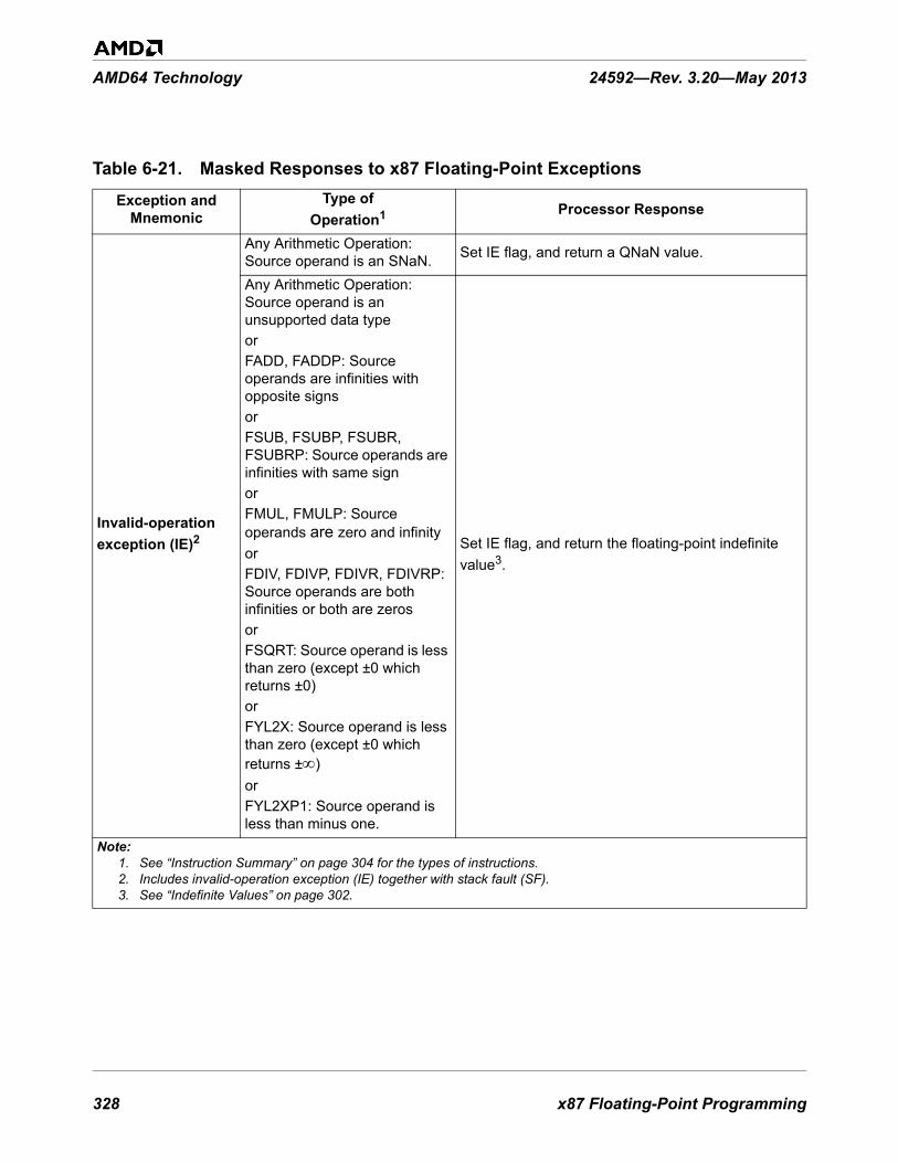
328 x87 Floating-Point Programming
AMD64 Technology 24592—Rev. 3.20—May 2013
Table 6-21. Masked Responses to x87 Floating-Point Exceptions
Exception and Mnemonic
Type of Operation1 Processor Response
Invalid-operation exception (IE)2
Any Arithmetic Operation: Source operand is an SNaN. Set IE flag, and return a QNaN value.
Any Arithmetic Operation: Source operand is an unsupported data typeorFADD, FADDP: Source operands are infinities with opposite signsorFSUB, FSUBP, FSUBR, FSUBRP: Source operands are infinities with same signorFMUL, FMULP: Source operands are zero and infinityorFDIV, FDIVP, FDIVR, FDIVRP: Source operands are both infinities or both are zerosorFSQRT: Source operand is less than zero (except ±0 which returns ±0)orFYL2X: Source operand is less than zero (except ±0 which returns ±∞)orFYL2XP1: Source operand is less than minus one.
Set IE flag, and return the floating-point indefinite value3.
Note:1. See “Instruction Summary” on page 304 for the types of instructions. 2. Includes invalid-operation exception (IE) together with stack fault (SF).3. See “Indefinite Values” on page 302.

x87 Floating-Point Programming 329
24592—Rev. 3.20—May 2013 AMD64 Technology
Invalid-operation exception (IE)2
FCOS, FPTAN, FSIN, FSINCOS: Source operand is ∞orFPREM, FPREM1: Dividend is infinity or divisor is 0.
Set IE flag, return the floating-point indefinite value3, and clear condition code C2 to 0.
FCOM, FCOMP, or FCOMPP: One or both operands is a NaNorFUCOM, FUCOMP, or FUCOMPP: One or both operands is an SNaN.
Set IE flag, and set C3–C0 condition codes to reflect the result.
FCOMI or FCOMIP: One or both operands is a NaNorFUCOMI or FUCOMIP: One or both operands is an SNaN.
Sets IE flag, and sets the result in eflags to "unordered."
FIST, FISTP, FISTTP: Source operand overflows the destination size.
Set IE flag, and return the integer indefinite value3.
FXCH: A source register is specified empty by its tag bits.
Set IE flag, and perform exchange using floating-point indefinite value3 as content for empty register(s).
FBSTP: Source operand overflows packed BCD data size.
Set IE flag, and return the packed-decimal indefinite value3.
Denormalized-operand exception (DE) Set DE flag, and return the result using the denormal operand(s).
Zero-divide exception (ZE)
FDIV, FDIVP, FDIVR, FDIVRP, FIDIV, or FIDIVR: Divisor is 0.
Set ZE flag, and return signed ∞ with sign bit = XOR of the operand sign bits.
FYL2X: ST(0) is 0 and ST(1) is a non-zero floating-point value.
Set ZE flag, and return signed ∞ with sign bit = complement of sign bit for ST(1) operand.
FXTRACT: Source operand is 0.
Set ZE flag, write ST(0) = 0 with sign of operand, and write ST(1) = –∞.
Table 6-21. Masked Responses to x87 Floating-Point Exceptions (continued)
Exception and Mnemonic
Type of Operation1 Processor Response
Note:1. See “Instruction Summary” on page 304 for the types of instructions. 2. Includes invalid-operation exception (IE) together with stack fault (SF).3. See “Indefinite Values” on page 302.

330 x87 Floating-Point Programming
AMD64 Technology 24592—Rev. 3.20—May 2013
Overflow exception (OE)
Round to nearest.
• If sign of result is positive, set OE flag, and return +∞.
• If sign of result is negative, set OE flag, and return -∞.
Round toward +∞.
• If sign of result is positive, set OE flag, and return +∞.
• If sign of result is negative, set OE flag, and return finite negative number with largest magnitude.
Round toward -∞.
• If sign of result is positive, set OE flag, and return finite positive number with largest magnitude.
• If sign of result is negative, set OE flag, and return -∞.
Round toward 0.
• If sign of result is positive, set OE flag and return finite positive number with largest magnitude.
• If sign of result is negative, set OE flag and return finite negative number with largest magnitude.
Underflow exception (UE)
• If result is both denormal (tiny) and inexact, set UE flag and return denormalized result.
• If result is denormal (tiny) but not inexact, return denormalized result but do not set UE flag.
Precision exception (PE)
Without overflow or underflowSet PE flag, return rounded result, write C1 condition code to specify round-up (C1 = 1) or not round-up (C1 = 0).
With masked overflow or underflow
Set PE flag and respond as for the OE or UE exceptions.
With unmasked overflow or underflow for register destination
Set PE flag, respond to the OE or UE exception by calling the #MF service routine.
With unmasked overflow or underflow for memory destination
Do not set PE flag, respond to the OE or UE exception by calling the #MF service routine. The destination and the TOP are not changed.
Table 6-21. Masked Responses to x87 Floating-Point Exceptions (continued)
Exception and Mnemonic
Type of Operation1 Processor Response
Note:1. See “Instruction Summary” on page 304 for the types of instructions. 2. Includes invalid-operation exception (IE) together with stack fault (SF).3. See “Indefinite Values” on page 302.
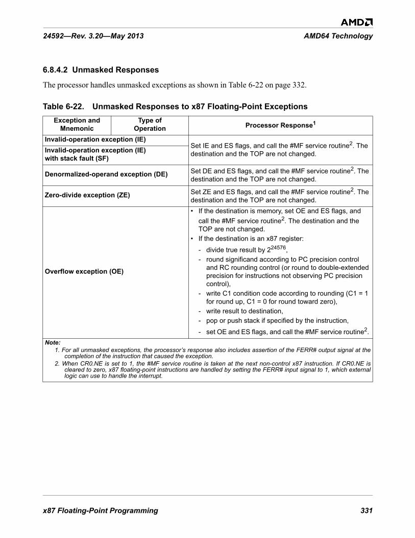
x87 Floating-Point Programming 331
24592—Rev. 3.20—May 2013 AMD64 Technology
6.8.4.2 Unmasked Responses
The processor handles unmasked exceptions as shown in Table 6-22 on page 332.
Table 6-22. Unmasked Responses to x87 Floating-Point ExceptionsException and
MnemonicType of
Operation Processor Response1
Invalid-operation exception (IE)Set IE and ES flags, and call the #MF service routine2. The destination and the TOP are not changed. Invalid-operation exception (IE)
with stack fault (SF)
Denormalized-operand exception (DE) Set DE and ES flags, and call the #MF service routine2. The destination and the TOP are not changed.
Zero-divide exception (ZE) Set ZE and ES flags, and call the #MF service routine2. The destination and the TOP are not changed.
Overflow exception (OE)
• If the destination is memory, set OE and ES flags, and call the #MF service routine2. The destination and the TOP are not changed.
• If the destination is an x87 register:
- divide true result by 224576, - round significand according to PC precision control
and RC rounding control (or round to double-extended precision for instructions not observing PC precision control),
- write C1 condition code according to rounding (C1 = 1 for round up, C1 = 0 for round toward zero),
- write result to destination, - pop or push stack if specified by the instruction,
- set OE and ES flags, and call the #MF service routine2. Note:
1. For all unmasked exceptions, the processor’s response also includes assertion of the FERR# output signal at thecompletion of the instruction that caused the exception.
2. When CR0.NE is set to 1, the #MF service routine is taken at the next non-control x87 instruction. If CR0.NE iscleared to zero, x87 floating-point instructions are handled by setting the FERR# input signal to 1, which externallogic can use to handle the interrupt.

332 x87 Floating-Point Programming
AMD64 Technology 24592—Rev. 3.20—May 2013
6.8.4.3 FERR# and IGNNE# Signals
In all unmasked-exception responses, the processor also asserts the FERR# output signal at the completion of the instruction that caused the exception. The exception is serviced at the boundary of the next non-waiting x87 or 64-bit media instruction following the instruction that caused the exception. (See “Control” on page 317 for a definition of control instructions.)
System software controls x87 floating-point exception reporting using the numeric error (NE) bit in control register 0 (CR0), as follows:
• If CR0.NE = 1, internal processor control over x87 floating-point exception reporting is enabled. In this case, an #MF exception occurs immediately. The FERR# output signal is asserted, but is not
Underflow exception (UE)
• If the destination is memory, set UE and ES flags, and call the #MF service routine2. The destination and the TOP are not changed.
• If the destination is an x87 register:
- multiply true result by 224576, - round significand according to PC precision control
and RC rounding control (or round to double-extended precision for instructions not observing PC precision control),
- write C1 condition code according to rounding (C1 = 1 for round up, C1 = 0 for round toward zero),
- write result to destination, - pop or push stack if specified by the instruction,
- set UE and ES flags, and call the #MF service routine2.
Precision exception (PE)
Without overflow or underflow
Set PE and ES flags, return rounded result, write C1 condition code to specify round-up (C1 = 1) or not round-up (C1 = 0), and call the #MF service routine2.
With masked overflow or underflow
Set PE and ES flags, respond as for the OE or UE exception, and call the #MF service routine2. With unmasked
overflow or underflow for register destinationWith unmasked overflow or underflow for memory destination
Do not set PE flag, respond to the OE or UE exception by calling the #MF service routine. The destination and the TOP are not changed.
Table 6-22. Unmasked Responses to x87 Floating-Point Exceptions (continued)Exception and
MnemonicType of
Operation Processor Response1
Note:1. For all unmasked exceptions, the processor’s response also includes assertion of the FERR# output signal at the
completion of the instruction that caused the exception.2. When CR0.NE is set to 1, the #MF service routine is taken at the next non-control x87 instruction. If CR0.NE is
cleared to zero, x87 floating-point instructions are handled by setting the FERR# input signal to 1, which externallogic can use to handle the interrupt.

x87 Floating-Point Programming 333
24592—Rev. 3.20—May 2013 AMD64 Technology
used externally. It is recommended that system software set NE to 1. This enables optimal performance in handling x87 floating-point exceptions.
• If CR0.NE = 0, internal processor control of x87 floating-point exceptions is disabled and the external IGNNE# input signal controls whether x87 floating-point exceptions are ignored, as follows:- When IGNNE# is 0, x87 floating-point exceptions are reported by asserting the FERR# output
signal, then stopping program execution until an external interrupt is detected. External logic use the FERR# signal to generate the external interrupt.
- When IGNNE# is 1, x87 floating-point exceptions do not stop program execution. After FERR# is asserted, instructions continue to execute.
6.8.4.4 Using NaNs in IE Diagnostic Exceptions
Both SNaNs and QNaNs can be encoded with many different values to carry diagnostic information. By means of appropriate masking and unmasking of the invalid-operation exception (IE), software can use signaling NaNs to invoke an exception handler. Within the constraints imposed by the encoding of SNaNs and QNaNs, software may freely assign the bits in the significand of a NaN. See the section “Not a Number (NaN)” on page 299 for format details.
For example, software can pre-load each element of an array with a signaling NaN that encodes the array index. When an application accesses an uninitialized array element, the invalid-operation exception is invoked and the service routine can identify that element. A service routine can store debug information in memory as the exceptions occur. The routine can create a QNaN that references its associated debug area in memory. As the program runs, the service routine can create a different QNaN for each error condition, so that a single test-run can identify a collection of errors.
6.9 State-SavingIn general, system software should save and restore x87 state between task switches or other interventions in the execution of x87 floating-point procedures. Virtually all modern operating systems running on x86 processors implement preemptive multitasking that handle saving and restoring of state across task switches, independent of hardware task-switch support. However, application procedures are also free to save and restore x87 state at any time they deem useful.
6.9.1 State-Saving Instructions
6.9.1.1 FSAVE/FNSAVE and FRSTOR Instructions
Application software can save and restore the x87 state by executing the FSAVE (or FNSAVE) and FRSTOR instructions. Alternatively, software may use multiple FxSTx (floating-point store stack top) instructions for saving only the contents of the x87 data registers, rather than the complete x87 state.
The FSAVE instruction stores the state, but only after handling any pending unmasked x87 floating-point exceptions, whereas the FNSAVE instruction skips the handling of these exceptions. The state of all x87 data registers is saved, as well as all x87 environment state (the x87 control word register,

334 x87 Floating-Point Programming
AMD64 Technology 24592—Rev. 3.20—May 2013
status word register, tag word, instruction pointer, data pointer, and last opcode register). After saving this state, the tag bits for all x87 registers are changed to empty and thus available for a new procedure.
6.9.1.2 FXSAVE and FXRSTOR Instructions
Application software can save and restore the 128-bit media state, 64-bit media state, and x87 floating-point state by executing the FXSAVE and FXRSTOR instructions. The FXSAVE and FXRSTOR instructions execute faster than FSAVE/FNSAVE and FRSTOR because they do not save and restore the x87 pointers (last instruction pointer, last data pointer, and last opcode, described in “Pointers and Opcode State” on page 289) except in the relatively rare cases in which the exception-summary (ES) bit in the x87 status word (the ES register image for FXSAVE, or the ES memory image for FXRSTOR) is set to 1, indicating that an unmasked x87 exception has occurred.
Unlike FSAVE and FNSAVE, however, FXSAVE does not alter the tag bits. The state of the saved x87 data registers is retained, thus indicating that the registers may still be valid (or whatever other value the tag bits indicated prior to the save). To invalidate the contents of the x87 data registers after FXSAVE, software must explicitly execute an FINIT instruction. Also, FXSAVE (like FNSAVE) and FXRSTOR do not check for pending unmasked x87 floating-point exceptions. An FWAIT instruction can be used for this purpose.
The architecture supports two memory formats for FXSAVE and FXRSTOR, a 512-byte 32-bit legacy format and a 512-byte 64-bit format, used in 64-bit mode. Selection of the 32-bit or 64-bit format is determined by the effective operand size for the FXSAVE and FXRSTOR instructions. For details, see “Media and x87 Processor State” in Volume 2.
6.10 Performance ConsiderationsIn addition to typical code optimization techniques, such as those affecting loops and the inlining of function calls, the following considerations may help improve the performance of application programs written with x87 floating-point instructions.
These are implementation-independent performance considerations. Other considerations depend on the hardware implementation. For information about such implementation-dependent considerations and for more information about application performance in general, see the data sheets and the software-optimization guides relating to particular hardware implementations.
6.10.1 Replace x87 Code with 128-Bit Media Code
Code written with 128-bit media floating-point instructions can operate in parallel on four times as many single-precision floating-point operands as can x87 floating-point code. This achieves potentially four times the computational work of x87 instructions that use single-precision operands. Also, the higher density of 128-bit media floating-point operands may make it possible to remove local temporary variables that would otherwise be needed in x87 floating-point code. 128-bit media code is easier to write than x87 floating-point code, because the XMM register file is flat rather than stack-oriented, and, in 64-bit mode there are twice the number of XMM registers as x87 registers.

x87 Floating-Point Programming 335
24592—Rev. 3.20—May 2013 AMD64 Technology
6.10.2 Use FCOMI-FCMOVx Branching
Depending on the hardware implementation of the architecture, the combination of FCOMI and FCMOVcc is often faster than the classical approach using FxSTSW AX instructions for comparison-based branches that depend on the condition codes for branch direction, because FNSTSW AX is often a serializing instruction.
6.10.3 Use FSINCOS Instead of FSIN and FCOS
Frequently, a piece of code that needs to compute the sine of an argument also needs to compute the cosine of that same argument. In such cases, use the FSINCOS instruction to compute both trigonometric functions concurrently, which is faster than using separate FSIN and FCOS instructions to accomplish the same task.
6.10.4 Break Up Dependency Chains
Parallelism can be increased by breaking up dependency chains or by evaluating multiple dependency chains simultaneously (explicitly switching execution between them). Depending on the hardware implementation of the architecture, the FXCH instruction may prove faster than FST/FLD pairs for switching execution between dependency chains.

336 x87 Floating-Point Programming
AMD64 Technology 24592—Rev. 3.20—May 2013

Index 337
24592—Rev. 3.20—May 2013 AMD64 Technology
Symbols#AC exception......................................................... 92#BP exception ......................................................... 91#BR exception......................................................... 91#DB exception......................................................... 91#DE exception......................................................... 91#DF exception ......................................................... 91#GP exception ......................................................... 92#MC exception ........................................................ 92#MF exception ......................................... 92, 272, 285#NM exception........................................................ 91#NP exception ......................................................... 92#OF exception ......................................................... 91#PF exception.......................................................... 92#SS exception.......................................................... 92#SX Exception ........................................................ 92#TS exception ......................................................... 92#UD exception ................................................. 91, 215#XF exception .................................................. 92, 215
Numerics16-bit mode............................................................ xix32-bit mode............................................................ xix3DNow!™ instructions .......................................... 2333DNow!™ technology ............................................... 464-bit media programming ..................................... 23364-bit mode........................................................ xix, 6AAAA instruction ................................................ 50, 74AAD instruction ................................................ 50, 74AAM instruction................................................ 50, 74AAS instruction................................................. 50, 74aborts...................................................................... 91absolute address....................................................... 16ADC instruction ...................................................... 53ADD instruction ...................................................... 53addition................................................................... 53ADDPD instruction................................................ 193ADDPS instruction ................................................ 193addressing
absolute address ................................................... 16address size............................................... 17, 72, 77branch address...................................................... 73canonical form ..................................................... 15complex address ................................................... 16effective address................................................... 15I/O ports ..................................................... 118, 243
IP-relative ...................................................... 16, 18linear ............................................................. 11, 12memory ............................................................... 14operands ............................................... 43, 116, 243PC-relative ..................................................... 16, 18RIP-relative................................................. xxiv, 18stack address ........................................................ 16string address ....................................................... 16virtual ............................................................ 11, 12x87 stack............................................................ 282
ADDSD instruction................................................ 193ADDSS instruction ................................................ 193ADDSUBPD instruction......................................... 196ADDSUBPS instruction ......................................... 196AES........................................................................ xxaffine ordering ............................................... 125, 299AH register........................................................ 25, 26AL register ........................................................ 25, 26alignment
64-bit media ....................................................... 244general-purpose ............................................ 43, 105SSE vector operands ........................................... 118
AND instruction ...................................................... 61ANDNPD instruction ............................................. 211ANDNPS instruction.............................................. 211ANDPD instruction................................................ 211ANDPS instruction ................................................ 211applications
media................................................................. 109arithmetic instructions ....................... 53, 256, 266, 309ARPL instruction ..................................................... 75array bounds ............................................................ 61ASCII adjust instructions.......................................... 50ASID ...................................................................... xxAX register........................................................ 25, 26
BB bit...................................................................... 286BCD data type ....................................................... 296BCD digits .............................................................. 40BH register ........................................................ 25, 26biased exponent ......................... xx, 121, 126, 294, 301binary-coded-decimal (BCD) digits ........................... 40bit scan instructions.................................................. 58bit strings ................................................................ 41bit test instructions ................................................... 59BL register ........................................................ 25, 26BLENDPD instruction............................................ 189BLENDPS instruction ............................................ 189
Index
338 Index
AMD64 Technology 24592—Rev. 3.20—May 2013
BLENDVPD instruction......................................... 189BLENDVPS instruction ......................................... 189BOUND instruction ........................................... 61, 74BP register ........................................................ 25, 26BPL register ............................................................ 26branch removal................................ 145, 175, 238, 262branch-address displacements ................................... 73branches............................................. 80, 88, 106, 227BSF instruction........................................................ 58BSR instruction ....................................................... 58BSWAP instruction .................................................. 51BT instruction ......................................................... 59BTC instruction ....................................................... 59BTR instruction ....................................................... 59BTS instruction ....................................................... 59busy (B) bit ........................................................... 286BX register........................................................ 25, 26byte ordering ..................................................... 14, 51byte registers ........................................................... 29
CC3–C0 bits ............................................................ 286cache .................................................................... 100
cachability ......................................................... 231coherency .......................................................... 102line.................................................................... 101management.................................................. 71, 103pollution ............................................................ 102prefetching......................................................... 103stale lines........................................................... 105
cache management instructions ................................. 71CALL instruction.......................................... 65, 74, 83caller-save parameter passing.................................. 226canonical address form............................................. 15carry flag................................................................. 35CBW instruction...................................................... 49CDQ instruction ...................................................... 49CDQE instruction .................................................... 49CH register........................................................ 25, 26CL register ........................................................ 25, 26clamping ............................................................... 119CLC instruction ....................................................... 68CLD instruction....................................................... 68clearing the MMX state ........................... 227, 249, 274CLFLUSH instruction .............................................. 71CLI instruction ........................................................ 68CMC instruction ...................................................... 68CMOVcc instructions............................................... 45CMP instruction ...................................................... 59CMPPD instruction................................................ 208CMPPS instruction ................................................ 208CMPS instruction .................................................... 62
CMPSB instruction .................................................. 62CMPSD instruction .......................................... 62, 208CMPSQ instruction .................................................. 62CMPSS instruction................................................. 208CMPSW instruction ................................................. 62CMPXCHG instruction ............................................ 70CMPXCHG16B instruction ...................................... 70CMPXCHG8B instruction ........................................ 70COMISD instruction .............................................. 210COMISS instruction............................................... 210commit.............................................................. xx, 97compare instructions ......................... 59, 261, 268, 314compatibility mode .............................................. xx, 7complex address ...................................................... 16condition codes (C3–C0) ........................................ 286conditional moves ............................................ 45, 307constants ............................................................... 308control instructions (x87)........................................ 317control transfers ........................................... 16, 63, 80control word .......................................................... 286CPUID instruction .............................. 70, 79, 270, 321CQO instruction....................................................... 49CR0.EM bit ........................................................... 292CRC32 instruction ................................................... 72CVTDQ2PD instruction ......................................... 153CVTDQ2PS instruction .......................................... 153CVTPD2DQ instruction ......................................... 186CVTPD2PI instruction ................................... 187, 265CVTPD2PS instruction........................................... 185CVTPI2PD instruction ................................... 154, 252CVTPI2PS instruction .................................... 154, 252CVTPS2DQ instruction .......................................... 186CVTPS2PD instruction........................................... 185CVTPS2PI instruction .................................... 187, 265CVTSD2SI instruction ........................................... 188CVTSD2SS instruction........................................... 185CVTSI2SD instruction ........................................... 154CVTSI2SS instruction ............................................ 154CVTSS2SD instruction........................................... 185CVTSS2SI instruction ............................................ 188CVTTPD2DQ instruction ....................................... 186CVTTPD2PI instruction ................................. 187, 265CVTTPS2DQ instruction........................................ 186CVTTPS2PI instruction.................................. 187, 265CVTTSD2SI instruction ......................................... 188CVTTSS2SI instruction.......................................... 188CWD instruction...................................................... 49CWDE instruction.................................................... 49CX register ........................................................ 25, 26

Index 339
24592—Rev. 3.20—May 2013 AMD64 Technology
DDAA instruction ................................................ 51, 74DAS instruction................................................. 51, 74data alignment ....................................................... 231data conversion instructions................ 49, 251, 265, 306data reordering instructions..................................... 252data transfer instructions............................ 45, 250, 306data types
128-bit media ..................................................... 130256-bit media ..................................................... 13264-bit media....................................................... 241floating-point ..................................................... 125general-purpose.................................................... 38mismatched........................................................ 226vector ................................................................ 109x87............................................................. 293, 299
DE bit ............................................................ 284, 325DEC instruction................................................. 54, 75decimal adjust instructions........................................ 51decrement ............................................................... 54default address size .................................................. 17default operand size ................................................. 29denormalized numbers .................................... 123, 297denormalized-operand exception (DE).............. 217, 325dependencies ......................................................... 106DH register ....................................................... 25, 26DI register ......................................................... 25, 26digital signal processing ......................................... 109DIL register............................................................. 26direct far jump ................................................... 63, 66direct referencing..................................................... xxdirection flag ........................................................... 36displacements ............................................... xx, 17, 73DIV instruction........................................................ 53division................................................................... 53DIVPD instruction ................................................. 197DIVPS instruction.................................................. 197DIVSD instruction ................................................. 197DIVSS instruction.................................................. 197DL register ........................................................ 25, 26DM bit .................................................................. 287dot product ..................................................... 143, 237double quadword .................................................... xxidouble-extended-precision format ........................... 295double-precision format .................................. 121, 295doubleword ............................................................ xxiDPPD instruction................................................... 200DPPS instruction ................................................... 200DX register ....................................................... 25, 26
EEAX register...................................................... 25, 26eAX–eSP register................................................. xxviiEBP register ...................................................... 25, 26EBX register...................................................... 25, 26ECX register...................................................... 25, 26EDI register ....................................................... 25, 26EDX register...................................................... 25, 26effective address ................................................ 15, 52effective address size............................................... xxieffective operand size ........................................ xxi, 42EFLAGS register ............................................... 25, 34eFLAGS register .................................................. xxviiEIP register.............................................................. 21eIP register .......................................................... xxviielement .................................................................. xxiEM bit................................................................... 292EMMS instruction.......................................... 249, 274empty............................................................ 273, 289emulation (EM) bit................................................. 292endian byte-ordering .................................. xxix, 14, 51ENTER instruction................................................... 47environment
x87 ............................................................ 291, 319ES bit.................................................................... 285ESI register........................................................ 25, 26ESP register....................................................... 25, 26exception status (ES) bit ......................................... 285exceptions ........................................................ xxi, 90
#MF causes ................................................ 272, 323#XF causes......................................................... 21564-bit media ....................................................... 271denormalized-operand (DE)......................... 217, 325general-purpose .................................................... 90inexact-result.............................................. 218, 326invalid-operation (IE).................................. 217, 324masked responses ............................................... 328masking ............................................................. 327overflow (OE) ............................................ 218, 326post-computation ................................................ 326precision (PE)............................................. 218, 326pre-computation ................................................. 326priority............................................................... 326SIMD floating-point causes ................................. 215SSE ................................................................... 213stack fault (SF) ................................................... 326underflow (UE) .......................................... 218, 326unmasked responses............................................ 332x87 .................................................................... 322zero-divide (ZE) ......................................... 217, 325
exit media state ...................................................... 249explicit integer bit .................................................. 294exponent ................................... xx, 121, 126, 294, 301

340 Index
AMD64 Technology 24592—Rev. 3.20—May 2013
extended SSE .................................................. xxi, 110AES .................................................................... xxAVX.................................................................... xxFMA .................................................................. xxiFMA4................................................................. xxiXOP ................................................................. xxvi
external interrupts .................................................... 90extract instructions.......................................... 254, 308EXTRACTPS instruction ....................................... 189EXTRQ instruction ................................................ 159
FF2XM1 instruction................................................. 313FABS instruction ................................................... 311FADD instruction .................................................. 309FADDP instruction ................................................ 309far calls ................................................................... 84far jumps................................................................. 82far returns................................................................ 86fault ........................................................................ 91FBLD instruction................................................... 307FBSTP instruction ................................................. 307FCMOVcc instructions .......................................... 308FCOM instruction.................................................. 314FCOMI instruction................................................. 314FCOMIP instruction............................................... 314FCOMP instruction................................................ 314FCOMPP instruction.............................................. 314FCOS instruction ................................................... 312FCW register ......................................................... 286FDECSTP instruction............................................. 316FDIV instruction.................................................... 311FDIVP instruction.................................................. 311FDIVR instruction ................................................. 311FDIVRP instruction ............................................... 311feature detection ...................................................... 79FEMMS instruction ........................................ 249, 274FERR ................................................................... 333FFREE instruction ................................................. 316FICOM instruction................................................. 315FICOMP instruction............................................... 315FIDIV instruction .................................................. 311FIMUL instruction................................................. 311FINCSTP instruction.............................................. 316FINIT instruction................................................... 317FIST instruction..................................................... 307FISTP instruction................................................... 307FISTTP instruction ................................................ 307FISUB instruction.................................................. 310flags instructions...................................................... 67FLAGS register ................................................. 25, 34FLD instruction ..................................................... 306
FLD1 instruction.................................................... 309FLDL2E instruction ............................................... 309FLDL2T instruction ............................................... 309FLDLG2 instruction............................................... 309FLDLN2 instruction............................................... 309FLDPI instruction .................................................. 309FLDZ instruction ................................................... 309floating-point data types ......................................... 120
128-bit media ..................................................... 130256-bit media ..................................................... 13264-bit media ....................................................... 245x87 .................................................................... 294
floating-point encodingunit in the last place (ulp) .................................... 128
floating-point instructions ........................................... 5flush....................................................................... xxiFMUL instruction .................................................. 310FMULP instruction ................................................ 310FNINIT instruction ................................................ 317FNOP instruction ................................................... 317FNSAVE instruction......................... 263, 264, 275, 319FPATAN instruction ............................................... 313FPR0–FPR7 registers ............................................. 282FPREM instruction ................................................ 312FPREM1 instruction............................................... 312FPTAN instruction ................................................. 313FPU control word................................................... 286FPU status word..................................................... 283FRNDINT instruction............................................. 312FRSTOR instruction................................ 263, 275, 319FS register ............................................................... 17FSAVE instruction ........................... 263, 264, 275, 319FSCALE instruction............................................... 313FSIN instruction .................................................... 312FSINCOS instruction ............................................. 312FST instruction ...................................................... 306FSTP instruction .................................................... 307FSUB instruction ................................................... 310FSUBP instruction ................................................. 310FSUBR instruction................................................. 310FSUBRP instruction............................................... 310FSW register.......................................................... 283FTST instruction.................................................... 315FTW register ......................................................... 288FUCOMx instructions ............................................ 315full................................................................ 273, 289FXAM instruction.................................................. 315FXCH instruction................................................... 308FXRSTOR instruction ...................... 179, 264, 275, 319FXSAVE instruction......................... 179, 264, 275, 319FXTRACT instruction............................................ 308FYL2X instruction ................................................. 313

Index 341
24592—Rev. 3.20—May 2013 AMD64 Technology
FYL2XP1 instruction ............................................. 313
Ggeneral-purpose instructions ....................................... 4general-purpose registers (GPRs) .............................. 23GPR ......................................................................... 3GPR registers .......................................................... 23GS register .............................................................. 17
HHADDPD instruction ............................................. 194HADDPS instruction.............................................. 194hidden integer bit ............................. 121, 123, 294, 297HSUBPD instruction.............................................. 195HSUBPS instruction .............................................. 195
II/O.......................................................................... 94
address space ....................................................... 94addresses ....................................................... 69, 94instructions .......................................................... 68memory-mapped .................................................. 95ports ................................................ 69, 94, 118, 243privilege level ...................................................... 96
IDIV instruction ...................................................... 53IE bit ............................................................. 284, 324IEEE 754 Standard........................... 114, 122, 280, 294IEEE-754 standard..................................................... 5IGN ...................................................................... xxiiIGNNE# input signal ............................................. 334IM bit ................................................................... 287immediate operands ...................................... 17, 42, 73implied integer bit........................................... 121, 294IMUL instruction..................................................... 53IN instruction .......................................................... 69INC instruction.................................................. 54, 75increment ................................................................ 54indefinite value
floating-point .............................................. 126, 302integer ........................................................ 126, 302packed-decimal .................................................. 302
indirect ................................................................. xxiiinexact-result exception........................... 218, 285, 326inexact-result exception (MXCSR PE bit)................ 114infinity........................................................... 124, 298infinity bit (Y) ....................................................... 288initialization
MSCSR register ................................................. 113x87 control word ................................................ 286XMM registers ................................................... 112
inner product .................................................. 143, 237input/output (I/O)..................................................... 94
INS instruction ........................................................ 69INSB instruction ...................................................... 69INSD instruction...................................................... 69insert instructions................................................... 254INSERTPS instruction............................................ 189INSERTQ instruction ............................................. 159instruction pointer .................................................... 20instruction prefixes
64-bit media ....................................................... 269general-purpose .................................................... 76legacy SSE......................................................... 212x87 .................................................................... 320
instruction set ............................................................ 4instruction-relative address ....................................... 16instructions
64-bit media ............................................... 247, 264arithmetic................................................... 161, 192data conversion........................................... 153, 185data reordering ........................................... 155, 189data transfer ............................................... 148, 180extract and insert ................................................ 159floating-point................................ 180, 239, 264, 280floating-point arithmetic ...................................... 192floating-point dot product .................................... 200floating-point rounding ....................................... 200fused multiply-add .............................................. 201general-purpose .................................................... 44I/O....................................................................... 99integer vector ..................................................... 161interleave ........................................................... 190invalid in 64-bit mode ........................................... 74locked.................................................................. 99memory ordering .................................................. 98non-temporal moves.................................... 151, 184pack................................................................... 156packed average ................................................... 169packed blending.................................................. 189prefixes................................................. 76, 269, 320reciprocal estimation ........................................... 199reciprocal square root.......................................... 199serializing ............................................................ 99shuffle ....................................................... 160, 190square root ......................................................... 198SSE floating-point .............................................. 180streaming store ........................................... 151, 184targeted application acceleration ............................ 72unpack and interleave.......................................... 157vector bit-wise.................................................... 211vector compare ........................................... 173, 208vector logical...................................................... 178vector shift ......................................................... 171x87 .................................................................... 304
INSW instruction ..................................................... 69INT instruction ........................................................ 66integer bit ........................................ 121, 123, 294, 297

342 Index
AMD64 Technology 24592—Rev. 3.20—May 2013
integer data types128-bit media ..................................................... 130256-bit media ..................................................... 13264-bit media....................................................... 244general-purpose.................................................... 38x87.................................................................... 295
interleave instructions ............................................ 253interrupt vector ........................................................ 90interrupts and exceptions .................................... 67, 90INTO instruction ............................................... 66, 74invalid-operation exception (IE)....................... 217, 324IOPL ...................................................................... 96IP register................................................................ 21IP-relative addressing...................................... 6, 16, 18IRET instruction ...................................................... 66IRETD instruction ................................................... 66IRETQ instruction ................................................... 67
JJ bit ............................................................... 121, 294Jcc instructions .................................................. 64, 82JMP instruction ................................................. 63, 74
LLAHF instruction..................................................... 68last data pointer ..................................................... 291last instruction pointer............................................ 290last opcode ............................................................ 290LDDQU instruction ............................................... 148LDMXCSR instruction .......................................... 179LDS instruction ................................................. 52, 74LEA instruction ....................................................... 52LEAVE instruction................................................... 47legacy mode ...................................................... xxii, 7legacy SSE..................................................... xxii, 110legacy x86............................................................. xxiiLES instruction.................................................. 52, 75LFENCE instruction ................................................ 71LFS instruction........................................................ 52LGS instruction ....................................................... 52limiting ................................................................. 119linear address .................................................... 11, 12LOCK prefix ........................................................... 78LODS instruction..................................................... 62LODSB instruction .................................................. 63LODSD instruction .................................................. 63LODSQ instruction .................................................. 63LODSW instruction ................................................. 63logarithmic functions ............................................. 313logarithms ............................................................. 309logical instructions............................................ 61, 262logical shift ............................................................. 56
long mode ......................................................... xxii, 6LOOPcc instructions ................................................ 65LSB ..................................................................... xxiiilsb........................................................................ xxiiiLSS instruction ........................................................ 52
Mmask ..................................................... xxiii, 114, 287masked responses................................................... 328MASKMOVDQU instruction ......................... 151, 251matrix operations ........................................... 143, 236MAXPD instruction ............................................... 209MAXPS instruction................................................ 209MAXSD instruction ............................................... 209MAXSS instruction................................................ 209MBZ.................................................................... xxiiimedia applications ............................................. 4, 109media context
saving and restoring state .................................... 179media instructions
128-bit ................................................................ xix256-bit ................................................................ xix64-bit .................................................................. xix
memoryaddressing ............................................................ 14hierarchy............................................................ 100management ................................................... 11, 71model .................................................................... 9optimization ......................................................... 97ordering ............................................................... 97physical ...................................................... xxiv, 11segmented ............................................................ 10virtual .................................................................... 9weakly ordered ..................................................... 96
memory management instructions ............................. 71memory-mapped I/O .......................................... 68, 95MFENCE instruction................................................ 71MINPD instruction................................................. 209MINPS instruction ................................................. 209MINSD instruction................................................. 209MINSS instruction ................................................. 209MMX registers ...................................................... 240MMX™ instructions .............................................. 233MMX™ technology ................................................... 4mnemonic syntax ................................................... 136modes
64-bit ..................................................................... 6compatibility .................................................... xx, 7legacy ............................................................ xxii, 7long ............................................................... xxii, 6mode switches ...................................................... 30operating............................................................ 2, 6protected ............................................ xxiv, 7, 13, 81
Index 343
24592—Rev. 3.20—May 2013 AMD64 Technology
real ................................................................... xxivreal mode......................................................... 7, 13virtual-8086 ............................................. xxvi, 7, 13
MOV instruction...................................................... 45MOV segReg instruction .......................................... 52MOVAPD instruction............................................. 181MOVAPS instruction ............................................. 181MOVD instruction .................................... 45, 148, 250MOVDDUP instruction................................... 181, 184MOVDQ2Q instruction ................................... 148, 250MOVDQA instruction............................................ 148MOVDQU instruction............................................ 148MOVHLPS instruction........................................... 181MOVHPD instruction ............................................ 181MOVHPS instruction ............................................. 181MOVLHPS instruction........................................... 181MOVLPD instruction............................................. 181MOVLPS instruction ............................................. 181MOVMSKPD instruction .................................. 50, 185MOVMSKPS instruction................................... 50, 184MOVNTDQ instruction .................................. 151, 251MOVNTDQA instruction....................................... 151MOVNTI instruction................................................ 45MOVNTPD instruction .......................................... 184MOVNTPS instruction........................................... 184MOVNTQ instruction ............................................ 250MOVNTSD instruction .......................................... 184MOVNTSS instruction........................................... 184MOVQ instruction .......................................... 148, 250MOVQ2DQ instruction ................................... 148, 250MOVS instruction.................................................... 62MOVSB instruction ................................................. 62MOVSD instruction .......................................... 62, 181MOVSHDUP instruction................................. 181, 184MOVSLDUP instruction ................................. 181, 184MOVSQ instruction ................................................. 62MOVSS instruction................................................ 181MOVSW instruction ................................................ 62MOVSX instruction ................................................. 45MOVUPD instruction ............................................ 181MOVUPS instruction ............................................. 181MOVZX instruction................................................. 45MSB.................................................................... xxiiimsb ..................................................................... xxiiiMSR.................................................................. xxviiiMUL instruction ...................................................... 53MULPD instruction ............................................... 197MULPS instruction ................................................ 197MULSD instruction ............................................... 197MULSS instruction ................................................ 197multiplication .......................................................... 53multiply-add.......................................................... 237
MXCSRDAZ bit ............................................................. 114DE bit ......................................................... 114, 217DM bit ............................................................... 114exception masks ................................................. 114FZ bit................................................................. 115IE bit .......................................................... 114, 217IM bit ................................................................ 114MM bit .............................................................. 115OE bit ......................................................... 114, 218OM bit ............................................................... 114PE bit.......................................................... 114, 218PM bit................................................................ 114RC field ............................................................. 115rounding control (RC) field ................................. 115UE bit ......................................................... 114, 218UM bit ............................................................... 114ZE bit ......................................................... 114, 217ZM bit ............................................................... 114
MXCSR register .................................................... 113
NNaN.............................................................. 124, 299near branches........................................................... 89near calls ................................................................. 84near jumps............................................................... 82near returns.............................................................. 86NEG instruction....................................................... 53NMI interrupt .......................................................... 91non-temporal data .................................................. 103non-temporal moves....................................... 141, 250non-temporal stores........................................ 105, 228NOP instruction ....................................................... 71normalized numbers ................................ 122, 123, 297not a number (NaN) ....................................... 124, 299NOT instruction....................................................... 61number encodings
floating-point...................................................... 125x87 .................................................................... 299
number representation64-bit media floating-point .................................. 245floating-point...................................................... 122x87 floating-point ............................................... 296
Ooctword................................................................ xxiiiOE bit ........................................................... 285, 326offset.................................................................... xxiiiOM bit .................................................................. 287opcode .............................................................. 7, 290operand size................ 29, 41, 73, 75, 77, 105, 227, 276operands
64-bit media ....................................................... 241

344 Index
AMD64 Technology 24592—Rev. 3.20—May 2013
addressing............................................................ 43general-purpose.................................................... 36SSE ................................................................... 116x87.................................................................... 292
operating modes .................................................... 2, 6operations
vector ......................................................... 109, 129OR instruction ......................................................... 61ordered compare ............................................. 211, 315ORPD instruction .................................................. 212ORPS instruction ................................................... 212OSXMMEXCPT bit............................................... 215OUT instruction....................................................... 69OUTS instruction..................................................... 69OUTSB instruction .................................................. 69OUTSD instruction .................................................. 69OUTSW instruction ................................................. 69overflow .............................................................. xxiiioverflow exception (OE) ................................. 218, 326overflow flag........................................................... 36
Ppack instructions.................................................... 252packed .................................................. xxiii, 109, 234packed BCD digits ................................................... 40packed-decimal data type ....................................... 296PACKSSDW instruction.................................. 156, 252PACKSSWB instruction.................................. 156, 252PACKUSDW instruction ........................................ 156PACKUSWB instruction ................................. 156, 252PADDB instruction ......................................... 162, 256PADDD instruction......................................... 162, 256PADDQ instruction......................................... 162, 256PADDSB instruction ....................................... 162, 256PADDSW instruction ...................................... 162, 256PADDUSB instruction ........................................... 162PADDUSW instruction .......................................... 162PADDW instruction ........................................ 162, 256PAE ..................................................................... xxivPAND instruction............................................ 178, 262PANDN instruction......................................... 178, 263parallel operations........................................... 109, 234parameter passing .................................................. 226parity flag................................................................ 35partial remainder.................................................... 312PAVGB instruction.......................................... 169, 259PAVGUSB instruction ............................................ 260PAVGW instruction......................................... 169, 259PBLENDVB instruction .................................. 157, 189PBLENDW instruction .......................................... 157PC field.......................................................... 287, 303PCMPEQB instruction .................................... 173, 261
PCMPEQD instruction ................................... 173, 261PCMPEQQ instruction ........................................... 174PCMPEQW instruction .................................. 173, 261PCMPESTRI instruction......................................... 177PCMPESTRM instruction ...................................... 177PCMPGTB instruction ................................... 174, 261PCMPGTD instruction ................................... 174, 261PCMPGTQ instruction ........................................... 174PCMPGTW instruction .................................. 174, 261PCMPISTRI instruction.......................................... 177PCMPISTRM instruction........................................ 177PC-relative addressing........................................ 16, 18PE bit............................................................ 285, 326performance considerations
64-bit media ....................................................... 276general-purpose .................................................. 105SSE media ......................................................... 227x87 .................................................................... 335
PEXTRB instruction .............................................. 159PEXTRD instruction .............................................. 159PEXTRQ instruction .............................................. 159PEXTRW instruction...................................... 159, 254PF2ID instruction................................................... 265PF2IW instruction.................................................. 265PFACC instruction ................................................. 266PFADD instruction................................................. 266PFCMPEQ instruction............................................ 268PFCMPGE instruction............................................ 269PFCMPGT instruction............................................ 268PFMAX instruction................................................ 269PFMIN instruction ................................................. 269PFMUL instruction ................................................ 266PFNACC instruction .............................................. 267PFPNACC instruction ............................................ 267PFRCP instruction ................................................. 268PFRCPIT1 instruction ............................................ 268PFRCPIT2 instruction ............................................ 268PFRSQIT1 instruction ............................................ 268PFRSQRT instruction............................................. 268PFSUB instruction ................................................. 266PFSUBR instruction............................................... 266PHMINPOSUW instruction.................................... 196physical memory............................................. xxiv, 11Pi.................................................................. 308, 313PI2FD instruction................................................... 252PI2FW instruction.................................................. 252PINSRB instruction................................................ 159PINSRD instruction ............................................... 159PINSRQ instruction ............................................... 159PINSRW instruction....................................... 159, 254PM bit................................................................... 287PMADDWD instruction ................................. 165, 258
Index 345
24592—Rev. 3.20—May 2013 AMD64 Technology
PMAXSB instruction ............................................. 175PMAXSD instruction ............................................. 175PMAXSW instruction ..................................... 175, 262PMAXUB instruction...................................... 175, 262PMAXUD instruction ............................................ 175PMAXUW instruction............................................ 175PMINSB instruction............................................... 175PMINSD instruction .............................................. 175PMINSW instruction....................................... 175, 262PMINUB instruction ....................................... 175, 262PMINUD instruction.............................................. 175PMINUW instruction ............................................. 175PMOVMSKB instruction ................................ 152, 251PMOVSXBD instruction........................................ 155PMOVSXBQ instruction........................................ 155PMOVSXBW instruction ....................................... 155PMOVSXDQ instruction........................................ 155PMOVSXWD instruction....................................... 155PMOVSXWQ instruction....................................... 155PMOVZXBD instruction........................................ 155PMOVZXBQ instruction........................................ 155PMOVZXBW instruction....................................... 155PMOVZXDQ instruction ....................................... 155PMOVZXWD instruction....................................... 155PMOVZXWQ instruction....................................... 155PMULDQ instruction............................................. 164PMULHRW instruction.......................................... 258PMULHUW instruction .................................. 164, 258PMULHW instruction ..................................... 164, 257PMULLD instruction ............................................. 164PMULLW instruction...................................... 164, 258PMULUDQ instruction ................................... 164, 258pointers................................................................... 19POP instruction ................................................. 47, 74POP segReg instruction............................................ 52POPA instruction ............................................... 47, 74POPAD instruction ............................................ 47, 74POPCNT................................................................. 58POPCNT instruction ................................................ 72POPF instruction ..................................................... 67POPFD instruction................................................... 67POPFQ instruction................................................... 67POR instruction .............................................. 178, 263post-computation exceptions................................... 326precision control (PC) field.............................. 287, 303precision exception (PE).................................. 218, 326pre-computation exceptions .................................... 326PREFETCH instruction..................................... 71, 104prefetching ............................................. 103, 106, 231PREFETCHlevel instruction.............................. 71, 104PREFETCHNTA instruction................................... 104
PREFETCHT0 instruction ...................................... 104PREFETCHT1 instruction ...................................... 104PREFETCHT2 instruction ...................................... 104PREFETCHW instruction................................. 71, 104prefixes
64-bit media ....................................................... 269general-purpose .................................................... 76media................................................................. 212REX .................................................................... 26x87 .................................................................... 320
priority of exceptions ............................................. 326privilege level .................................................... 81, 92probe.................................................................... xxivprocedure calls......................................................... 83procedure stack........................................................ 81processor features .................................................... 79processor identification............................................. 70processor modes
16-bit .................................................................. xix32-bit .................................................................. xix64-bit .................................................................. xix
program order .......................................................... 97programming model
64-bit media ....................................................... 233x87 .................................................................... 279
protected mode ........................................... xxiv, 7, 13PSADBW instruction ..................................... 170, 260pseudo-denormalized numbers ................................ 298pseudo-infinity....................................................... 296pseudo-NaN .......................................................... 296PSHUFB instruction............................................... 160PSHUFD instruction .............................................. 160PSHUFHW instruction ........................................... 160PSHUFLW instruction............................................ 160PSHUFW instruction.............................................. 255PSLLD instruction ......................................... 171, 260PSLLDQ instruction............................................... 171PSLLQ instruction ......................................... 171, 260PSLLW instruction......................................... 171, 260PSRAD instruction......................................... 172, 261PSRAW instruction ........................................ 172, 261PSRLD instruction ......................................... 172, 260PSRLDQ instruction .............................................. 172PSRLQ instruction ......................................... 172, 260PSRLW instruction ........................................ 171, 260PSUBB instruction......................................... 163, 257PSUBD instruction......................................... 163, 257PSUBQ instruction......................................... 163, 257PSUBSB instruction....................................... 163, 257PSUBSW instruction...................................... 163, 257PSUBUSB instruction ............................................ 163PSUBUSW instruction ........................................... 163

346 Index
AMD64 Technology 24592—Rev. 3.20—May 2013
PSUBW instruction......................................... 163, 257PSWAPD instruction.............................................. 255PTEST instruction ................................................. 178PUNPCKHBW instruction .............................. 157, 253PUNPCKHDQ instruction...................................... 157PUNPCKHQDQ instruction ................................... 157PUNPCKHWD instruction ..................................... 157PUNPCKLBW instruction............................... 157, 253PUNPCKLDQ instruction ............................... 157, 253PUNPCKLQDQ instruction.................................... 157PUNPCKLWD instruction............................... 157, 253PUSH instruction............................................... 47, 74PUSHA instruction ............................................ 47, 74PUSHAD instruction.......................................... 47, 74PUSHF instruction................................................... 67PUSHFD instruction ................................................ 67PUSHFQ instruction ................................................ 67PXOR instruction ........................................... 179, 263
QQNaN ............................................................ 124, 299quadword ............................................................. xxivquiet NaN (QNaN).......................................... 124, 299
RR8B–R15B registers ................................................ 26R8D–R15D registers ................................................ 26r8–r15................................................................ xxviiiR8–R15 registers ..................................................... 26R8W–R15W registers .............................................. 26range of values
64-bit media................................................ 244, 246floating-point data types...................................... 121x87.................................................................... 295
RAX register ........................................................... 26rAX–rSP ............................................................ xxviiiRAZ .................................................................... xxivRBP register ............................................................ 26rBP register ............................................................. 20RBX register ........................................................... 26RC field ......................................................... 288, 303RCL instruction ....................................................... 55RCPPS instruction ................................................. 199RCPSS instruction ................................................. 199RCR instruction....................................................... 55RCX register ........................................................... 26RDI register ............................................................ 26RDX register ........................................................... 26read order................................................................ 97real address mode. See real modereal mode .................................................... xxiv, 7, 13real numbers................................................... 122, 297
reciprocal estimation .............................................. 267reciprocal square root ............................................. 268register extensions.............................................. 1, 3, 6registers .................................................................... 3
128-bit media ..................................................... 111256-bit media ..................................................... 11164-bit media ....................................................... 240eAX–eSP ......................................................... xxviieFLAGS .......................................................... xxviiEIP ...................................................................... 21eIP................................................................... xxviiextensions .......................................................... 1, 3IP ........................................................................ 21MMX ................................................................ 240r8–r15............................................................. xxviiirAX–rSP ......................................................... xxviiirFLAGS............................................................ xxixRIP...................................................................... 21rIP .............................................................. xxix, 21segment ............................................................... 17x87 control word ................................................ 286x87 last data pointer ............................................ 291x87 last opcode................................................... 290x87 last-instruction pointer .................................. 290x87 physical ....................................................... 282x87 stack............................................................ 281x87 status word .................................................. 283x87 tag word ...................................................... 288XMM ................................................................ 111YMM ................................................................ 111
relative ................................................................. xxivremainder .............................................................. 312REP prefix............................................................... 78REPE prefix ............................................................ 78repeat prefixes ................................................. 78, 107REPNE prefix.......................................................... 78REPNZ prefix.......................................................... 78REPZ prefix ............................................................ 78reserved ............................................................... xxivreset
power-on............................................................ 113restoring state ........................................................ 334RET instruction ................................................. 66, 86revision history ........................................................ xvREX..................................................................... xxivREX prefixes ................................................. 6, 26, 79RFLAGS register ............................................... 26, 34rFLAGS Register
AF bit .................................................................. 35carry flag ............................................................. 35CF bit .................................................................. 35DF bit .................................................................. 36direction flag ........................................................ 36OF bit .................................................................. 36

Index 347
24592—Rev. 3.20—May 2013 AMD64 Technology
overflow flag........................................................ 36parity flag ............................................................ 35PF bit .................................................................. 35SF bit .................................................................. 36sign flag............................................................... 36zero flag .............................................................. 35ZF bit .................................................................. 35
rFLAGS register ................................................... xxixRIP register ....................................................... 21, 26rIP register ...................................................... xxix, 21RIP-relative addressing .................................... xxiv, 18RIP-relative data addressing ....................................... 6ROL instruction....................................................... 55ROR instruction....................................................... 55rotate instructions .................................................... 55rounding
64-bit media................................................ 245, 247floating-point ..................................................... 127x87..................................................... 288, 303, 311
rounding control (RC) field ............................. 288, 303ROUNDPD instruction .......................................... 200ROUNDPS instruction ........................................... 200ROUNDSD instruction .......................................... 200ROUNDSS instruction ........................................... 200RSI register ............................................................. 26RSP register ...................................................... 26, 83rSP register ............................................................. 20RSQRTPS instruction............................................. 199RSQRTSS instruction............................................. 199
SSAHF instruction..................................................... 68SAL instruction ....................................................... 55SAR instruction ....................................................... 55saturation
64-bit media....................................................... 244media instruction ................................................ 119
saving state ..................................... 226, 263, 274, 334SBB instruction ....................................................... 53SBZ...................................................................... xxvscalar .................................................................... xxvscalar product ................................................. 143, 237SCAS instruction ..................................................... 62SCASB instruction................................................... 62SCASD instruction .................................................. 62SCASQ instruction .................................................. 62SCASW instruction.................................................. 62scientific programming........................................... 110segment override ..................................................... 78segment registers ..................................................... 17segmented memory .................................................. 10self-modifying code ............................................... 102
semaphore instructions ............................................. 69set......................................................................... xxvSETcc instructions ................................................... 60SF bit ............................................................ 285, 326SFENCE instruction................................................. 71shift instructions .............................................. 55, 260SHL instruction ....................................................... 55SHLD instruction..................................................... 55SHR instruction ....................................................... 55SHRD instruction..................................................... 55shuffle instructions ................................................. 255SHUFPD instruction .............................................. 190SHUFPS instruction ............................................... 190SI register.......................................................... 25, 26SIB ....................................................................... xxvsign......................................... 119, 126, 244, 301, 311sign extension .......................................................... 49sign flag .................................................................. 36sign masks............................................................... 50signaling NaN (SNaN) ................................... 124, 299significand....................................... 121, 126, 294, 301SIL register.............................................................. 26SIMD.................................................................... xxvSIMD exceptions
masked responses ............................................... 221masking ............................................................. 221post-computation ................................................ 219pre-computation ................................................. 219priority of........................................................... 219unmasked responses............................................ 224
SIMD floating-point exceptions .............................. 215SIMD operations............................................ 109, 234single-instruction, multiple-data (SIMD)...................... 4single-precision format ............................ 121, 246, 295SNaN............................................................ 124, 299software interrupts ............................................. 67, 90SP register ......................................................... 25, 26spatial locality ....................................................... 103speculative execution ............................................... 97SPL register............................................................. 26SQRTPD instruction............................................... 198SQRTPS instruction ............................................... 198SQRTSD instruction............................................... 198SQRTSS instruction ............................................... 198square root..................................................... 268, 312SSE floating-point instructions................................ 180SSE Instructions ............................................. xxv, 110
extended ..................................................... xxi, 110legacy ........................................................ xxii, 110
SSE instructionsAES............................................................. xx, 110AVX ............................................................ xx, 110

348 Index
AMD64 Technology 24592—Rev. 3.20—May 2013
CLMUL............................................................. 110FMA ........................................................... xxi, 110FMA4.......................................................... xxi, 110overview............................................................ 109SSE1 .......................................................... xxv, 110SSE2 .......................................................... xxv, 110SSE3 .......................................................... xxv, 110SSE4.1 ....................................................... xxv, 110SSE4.2 ....................................................... xxv, 110SSE4A........................................................ xxv, 110SSSE3 ........................................................ xxv, 110XOP .......................................................... xxvi, 110
ST(0)–ST(7) registers............................................. 282stack ................................................................ 81, 226
address ................................................................ 16allocation ........................................................... 106frame............................................................. 19, 47operand size ......................................................... 82operations ............................................................ 47pointer ........................................................... 19, 81x87 stack fault .................................................... 326x87 stack management ........................................ 316x87 stack overflow ............................................. 326x87 stack underflow............................................ 326
stack fault (SF) exceptions...................................... 326state saving ..................................... 226, 263, 274, 334status word............................................................ 283STC instruction ....................................................... 68STD instruction ....................................................... 68STI instruction......................................................... 68sticky bits.............................................. xxvi, 113, 284STMXCSR instruction ........................................... 179STOS instruction ..................................................... 63STOSB instruction................................................... 63STOSD instruction................................................... 63STOSQ instruction................................................... 63STOSW instruction.................................................. 63Streaming SIMD Extensions (SSE) ......................... xxvstreaming store ....................................... 141, 228, 250string address .......................................................... 16string instructions .............................................. 62, 69strings..................................................................... 40SUB instruction ....................................................... 53SUBPD instruction ................................................ 195SUBPS instruction ................................................. 194SUBSD instruction ................................................ 195SUBSS instruction ................................................. 195subtraction .............................................................. 53sum of absolute differences..................................... 260swap instructions ................................................... 255SYSCALL instruction ........................................ 72, 88SYSENTER instruction................................. 72, 74, 88SYSEXIT instruction .................................... 72, 74, 88
SYSRET instruction........................................... 72, 88system call and return instructions ....................... 72, 88
Ttag bits .......................................................... 273, 288tag word ................................................................ 288task switch............................................................... 85task-state segment (TSS) .......................................... 85temporal locality .................................................... 103TEST instruction...................................................... 59test instructions................................................ 59, 314tiny numbers............................ 123, 217, 218, 297, 325TOP field ...................................................... 282, 286top-of-stack pointer (TOP)....................... 273, 282, 286transcendental instructions ...................................... 312trap ......................................................................... 91trigonometric functions........................................... 312TSS...................................................................... xxvi
UUCOMISD instruction............................................ 210UCOMISS instruction ............................................ 210UE bit ........................................................... 285, 326ulp ................................................................ 128, 304UM bit .................................................................. 287underflow..................................................... xxvi, 326underflow exception (UE)............................... 218, 326unit in the last place (ulp)........................................ 304unmask .......................................................... 114, 287unmasked responses ............................................... 332unnormal numbers ................................................. 296unordered compare.......................................... 211, 315unpack instructions ........................................ 189, 253UNPCKHPD instruction......................................... 190UNPCKHPS instruction ......................................... 190UNPCKLPD instruction ......................................... 190UNPCKLPS instruction.......................................... 190unsupported number types ...................................... 296
VVADDPD instruction.............................................. 193VADDPS instruction .............................................. 193VADDSD instruction.............................................. 193VADDSS instruction .............................................. 193VADDSUBPD instruction....................................... 196VADDSUBPS instruction ....................................... 196VANDNPD instruction ........................................... 211VANDNPS instruction............................................ 211VANDPD instruction.............................................. 211VANDPS instruction .............................................. 211VBLENDPD instruction ......................................... 189

Index 349
24592—Rev. 3.20—May 2013 AMD64 Technology
VBLENDPS instruction ......................................... 189VBLENDVPD instruction ...................................... 189VBLENDVPS instruction....................................... 189VCMPPD instruction ............................................. 208VCMPPS instruction.............................................. 208VCMPSD instruction ............................................. 208VCMPSS instruction.............................................. 208VCOMISD instruction ........................................... 210VCOMISS instruction ............................................ 210VCVTDQ2PD instruction ...................................... 153VCVTDQ2PS instruction ....................................... 153VCVTPD2DQ instruction ...................................... 186VCVTPD2PS instruction........................................ 185VCVTPS2DQ instruction ....................................... 186VCVTPS2PD instruction........................................ 185VCVTSD2SI instruction ........................................ 188VCVTSD2SS instruction........................................ 185VCVTSI2SD instruction ........................................ 154VCVTSI2SS instruction ......................................... 154VCVTSS2SD instruction........................................ 185VCVTSS2SI instruction ......................................... 188VCVTTPD2DQ instruction .................................... 186VCVTTPS2DQ instruction..................................... 186VCVTTSD2SI instruction ...................................... 188VCVTTSS2SI instruction....................................... 188VDIVPD instruction .............................................. 197VDIVPS instruction ............................................... 197VDIVSD instruction .............................................. 197VDIVSS instruction ............................................... 197VDPPD instruction ................................................ 200VDPPS instruction................................................. 200vector ........................................................... xxvi, 109vector operations .................................... 109, 129, 234VEXTRACTPS instruction..................................... 189VFMADD132PD instruction .................................. 205VFMADD132PS instruction................................... 205VFMADD132SD instruction .................................. 205VFMADD132SS instruction................................... 205VFMADD213PD instruction .................................. 205VFMADD213PS instruction................................... 205VFMADD213SD instruction .................................. 205VFMADD213SS instruction................................... 205VFMADD231PD instruction .................................. 205VFMADD231PS instruction................................... 205VFMADD231SD instruction .................................. 205VFMADD231SS instruction................................... 205VFMADDPD instruction........................................ 205VFMADDPS instruction ........................................ 205VFMADDSD instruction........................................ 205VFMADDSS instruction ........................................ 205VFMADDSUB132PD instruction ........................... 205
VFMADDSUB132PS instruction ............................ 206VFMADDSUB213PD instruction ........................... 205VFMADDSUB213PS instruction ............................ 206VFMADDSUB231PD instruction ........................... 205VFMADDSUB231PS instruction ............................ 206VFMADDSUBPD instruction................................. 205VFMADDSUBPS instruction ................................. 206VFMSUB132PD instruction ................................... 206VFMSUB132PS instruction.................................... 206VFMSUB132SD instruction ................................... 206VFMSUB132SS instruction.................................... 207VFMSUB213PD instruction ................................... 206VFMSUB213PS instruction.................................... 206VFMSUB213SD instruction ................................... 206VFMSUB213SS instruction.................................... 207VFMSUB231PD instruction ................................... 206VFMSUB231PS instruction.................................... 206VFMSUB231SD instruction ................................... 206VFMSUB231SS instruction.................................... 207VFMSUBADD132PD instruction ........................... 206VFMSUBADD132PS instruction ............................ 206VFMSUBADD213PD instruction ........................... 206VFMSUBADD213PS instruction ............................ 206VFMSUBADD231PD instruction ........................... 206VFMSUBADD231PS instruction ............................ 206VFMSUBADDPD instruction................................. 206VFMSUBADDPS instruction ................................. 206VFMSUBPD instruction......................................... 206VFMSUBPS instruction ......................................... 206VFMSUBSD instruction......................................... 206VFMSUBSS instruction ......................................... 207VFNMADD132PD instruction................................ 207VFNMADD132PS instruction ................................ 207VFNMADD132SD instruction................................ 207VFNMADD132SS instruction ................................ 207VFNMADD213PD instruction................................ 207VFNMADD213PS instruction ................................ 207VFNMADD213SD instruction................................ 207VFNMADD213SS instruction ................................ 207VFNMADD231PD instruction................................ 207VFNMADD231PS instruction ................................ 207VFNMADD231SD instruction................................ 207VFNMADD231SS instruction ................................ 207VFNMADDPD instruction ..................................... 207VFNMADDPS instruction ...................................... 207VFNMADDSD instruction ..................................... 207VFNMADDSS instruction ...................................... 207VFNMSUB132PD instruction................................. 207VFNMSUB132PS instruction ................................. 207VFNMSUB132SD instruction................................. 208VFNMSUB132SS instruction ................................. 208

350 Index
AMD64 Technology 24592—Rev. 3.20—May 2013
VFNMSUB213PD instruction ................................ 207VFNMSUB213PS instruction ................................. 207VFNMSUB213SD instruction ................................ 208VFNMSUB213SS instruction ................................. 208VFNMSUB231PD instruction ................................ 207VFNMSUB231PS instruction ................................. 207VFNMSUB231SD instruction ................................ 208VFNMSUB231SS instruction ................................. 208VFNMSUBPD instruction...................................... 207VFNMSUBPS instruction ...................................... 207VFNMSUBSD instruction...................................... 208VFNMSUBSS instruction ...................................... 208VHADDPD instruction .......................................... 194VHADDPS instruction ........................................... 194VHSUBPD instruction ........................................... 195VHSUBPS instruction............................................ 195VINSERTPS instruction ......................................... 189virtual address ................................................... 11, 12virtual memory .......................................................... 9virtual-8086 mode........................................ xxvi, 7, 13VLDDQU instruction............................................. 148VLDMXCSR instruction........................................ 179VMASKMOVDQU instruction............................... 151VMAXPD instruction ............................................ 209VMAXPS instruction ............................................. 209VMAXSD instruction ............................................ 209VMAXSS instruction ............................................. 209VMINPD instruction.............................................. 209VMINPS instruction .............................................. 209VMINSD instruction.............................................. 209VMINSS instruction .............................................. 209VMOVAPD instruction .......................................... 181VMOVAPS instruction........................................... 181VMOVD instruction .............................................. 148VMOVDDUP instruction ................................ 181, 184VMOVDQA instruction ......................................... 148VMOVDQU instruction ......................................... 148VMOVHLPS instruction ........................................ 181VMOVHPD instruction.......................................... 181VMOVHPS instruction .......................................... 181VMOVLHPS instruction ........................................ 181VMOVLPD instruction .......................................... 181VMOVLPS instruction........................................... 181VMOVMSKPD instruction .................................... 185VMOVMSKPS instruction ..................................... 184VMOVNTDQ instruction....................................... 151VMOVNTDQA instruction .................................... 151VMOVNTPD instruction ....................................... 184VMOVNTPS instruction ........................................ 184VMOVQ instruction .............................................. 148VMOVSD instruction ............................................ 181
VMOVSHDUP instruction ............................. 181, 184VMOVSLDUP instruction.............................. 181, 184VMOVSS instruction ............................................. 181VMOVUPD instruction .......................................... 181VMOVUPS instruction........................................... 181VMULPD instruction ............................................. 197VMULPS instruction.............................................. 197VMULSD instruction ............................................. 197VMULSS instruction.............................................. 197VORPD instruction ................................................ 212VORPS instruction................................................. 212VPACKSSDW instruction ...................................... 156VPACKSSWB instruction ...................................... 156VPACKUSDW instruction...................................... 156VPACKUSWB instruction...................................... 156VPADDB instruction.............................................. 162VPADDD instruction.............................................. 162VPADDQ instruction.............................................. 162VPADDSB instruction............................................ 162VPADDSW instruction........................................... 162VPADDUSB instruction ......................................... 162VPADDUSW instruction ........................................ 162VPADDW instruction............................................. 162VPAND instruction ................................................ 178VPANDN instruction.............................................. 178VPAVGB instruction .............................................. 169VPAVGW instruction ............................................. 169VPBLENDVB instruction............................... 157, 189VPBLENDW instruction ........................................ 157VPCMPEQB instruction......................................... 173VPCMPEQD instruction......................................... 173VPCMPEQQ instruction......................................... 174VPCMPEQW instruction........................................ 173VPCMPESTRI instruction ...................................... 177VPCMPESTRM instruction.................................... 177VPCMPGTB instruction......................................... 174VPCMPGTD instruction......................................... 174VPCMPGTQ instruction......................................... 174VPCMPGTW instruction........................................ 174VPCMPISTRI instruction ....................................... 177VPCMPISTRM instruction..................................... 177VPCOMB instruction ............................................. 176VPCOMD instruction............................................. 176VPCOMQ instruction............................................. 176VPCOMUB instruction .......................................... 176VPCOMUD instruction .......................................... 176VPCOMUQ instruction .......................................... 176VPCOMUW instruction ......................................... 176VPCOMW instruction ............................................ 176VPEXTRB instruction............................................ 159VPEXTRD instruction............................................ 159

Index 351
24592—Rev. 3.20—May 2013 AMD64 Technology
VPEXTRQ instruction ........................................... 159VPEXTRW instruction........................................... 159VPHADDBD instruction........................................ 169VPHADDBQ instruction........................................ 169VPHADDBW instruction ....................................... 169VPHADDDQ instruction........................................ 169VPHADDUBD instruction ..................................... 169VPHADDUBQ instruction ..................................... 169VPHADDUBW instruction .................................... 169VPHADDUDQ instruction ..................................... 169VPHADDUWD instruction .................................... 169VPHADDUWQ instruction .................................... 169VPHADDWD instruction....................................... 169VPHADDWQ instruction....................................... 169VPHMINPOSUW instruction ................................. 196VPHSUBBW instruction........................................ 169VPHSUBDQ instruction ........................................ 169VPHSUBWD instruction........................................ 169VPINSRB instruction............................................. 159VPINSRD instruction............................................. 159VPINSRQ instruction............................................. 159VPINSRW instruction ............................................ 159VPMACSDD instruction........................................ 167VPMACSDQH instruction ..................................... 168VPMACSDQL instruction...................................... 168VPMACSSDD instruction...................................... 167VPMACSSDQH instruction ................................... 168VPMACSSDQL instruction.................................... 167VPMACSSWD instruction ..................................... 167VPMACSSWW instruction .................................... 167VPMACSWD instruction ....................................... 167VPMACSWW instruction ...................................... 167VPMADCSSWD instruction .................................. 168VPMADCSWD instruction .................................... 168VPMADDWD instruction ...................................... 165VPMAXSB instruction .......................................... 175VPMAXSD instruction .......................................... 175VPMAXSW instruction ......................................... 175VPMAXUB instruction .......................................... 175VPMAXUD instruction.......................................... 175VPMAXUW instruction ......................................... 175VPMINSB instruction ............................................ 175VPMINSD instruction............................................ 175VPMINSW instruction ........................................... 175VPMINUB instruction ........................................... 175VPMINUD instruction ........................................... 175VPMINUW instruction .......................................... 175VPMOVMSKB instruction..................................... 152VPMOVSXBD instruction ..................................... 155VPMOVSXBQ instruction ..................................... 155VPMOVSXBW instruction .................................... 155
VPMOVSXDQ instruction ..................................... 155VPMOVSXWD instruction .................................... 155VPMOVSXWQ instruction .................................... 155VPMOVZXBD instruction ..................................... 155VPMOVZXBQ instruction ..................................... 155VPMOVZXBW instruction .................................... 155VPMOVZXDQ instruction ..................................... 155VPMOVZXWD instruction .................................... 155VPMOVZXWQ instruction .................................... 155VPMULDQ instruction .......................................... 164VPMULHUW instruction ....................................... 164VPMULHW instruction.......................................... 164VPMULLD instruction........................................... 164VPMULLW instruction .......................................... 164VPMULUDQ instruction........................................ 164VPOR instruction................................................... 178VPROTB instruction .............................................. 173VPROTD instruction.............................................. 173VPROTQ instruction.............................................. 173VPROTW instruction ............................................. 173VPSADBW instruction........................................... 170VPSHAB instruction .............................................. 173VPSHAD instruction.............................................. 173VPSHAQ instruction.............................................. 173VPSHAW instruction ............................................. 173VPSHLB instruction .............................................. 173VPSHLD instruction .............................................. 173VPSHLQ instruction .............................................. 173VPSHLW instruction.............................................. 173VPSHUFB instruction ............................................ 160VPSHUFD instruction............................................ 160VPSHUFHW instruction ........................................ 160VPSHUFLW instruction ......................................... 160VPSLLD instruction............................................... 171VPSLLDQ instruction ............................................ 171VPSLLQ instruction............................................... 171VPSLLW instruction .............................................. 171VPSRAD instruction .............................................. 172VPSRAW instruction ............................................. 172VPSRLD instruction .............................................. 172VPSRLDQ instruction............................................ 172VPSRLQ instruction .............................................. 172VPSRLW instruction.............................................. 171VPSUBB instruction .............................................. 163VPSUBD instruction .............................................. 163VPSUBQ instruction .............................................. 163VPSUBSB instruction ............................................ 163VPSUBSW instruction ........................................... 163VPSUBUSB instruction.......................................... 163VPSUBUSW instruction......................................... 163VPSUBW instruction ............................................. 163

352 Index
AMD64 Technology 24592—Rev. 3.20—May 2013
VPTEST instruction............................................... 178VPUNPCKHBW instruction................................... 157VPUNPCKHDQ instruction ................................... 157VPUNPCKHQDQ instruction................................. 157VPUNPCKHWD instruction .................................. 157VPUNPCKLBW instruction ................................... 157VPUNPCKLDQ instruction.................................... 157VPUNPCKLQDQ instruction ................................. 157VPUNPCKLWD instruction ................................... 157VPXOR instruction................................................ 179VRCPPS instruction............................................... 199VRCPSS instruction............................................... 199VROUNDPD instruction........................................ 200VROUNDPS instruction ........................................ 200VROUNDSD instruction........................................ 200VROUNDSS instruction ........................................ 200VRSQRTPS instruction .......................................... 199VRSQRTSS instruction .......................................... 199VSHUFPD instruction............................................ 190VSHUFPS instruction ............................................ 190VSQRTPD instruction............................................ 198VSQRTPS instruction ............................................ 198VSQRTSD instruction............................................ 198VSQRTSS instruction ............................................ 198VSTMXCSR instruction ........................................ 179VSUBPD instruction.............................................. 195VSUBPS instruction .............................................. 194VSUBSD instruction.............................................. 195VSUBSS instruction .............................................. 195VUCOMISD instruction......................................... 210VUCOMISS instruction ......................................... 210VUNPCKHPD instruction...................................... 190VUNPCKHPS instruction ...................................... 190VUNPCKLPD instruction ...................................... 190VUNPCKLPS instruction....................................... 190VXORPD instruction ............................................. 212VXORPS instruction.............................................. 212
Wweakly ordered memory ........................................... 96write buffers .......................................................... 101write combining....................................................... 98write order .............................................................. 98
Xx87 Control Word Register
ZM bit ............................................................... 287x87 control word register........................................ 286x87 environment............................................. 291, 319x87 floating-point programming ............................. 279x87 instructions ......................................................... 4x87 Status Word Register
ZE bit ........................................................ 285, 325x87 status word register .......................................... 283x87 tag word register.............................................. 288XADD instruction.................................................... 70XCHG instruction .................................................... 70XLAT instruction ..................................................... 50XMM registers ...................................................... 111XOP
Instructions ....................................................... xxviPrefix................................................................ xxvi
XOR instruction....................................................... 61XORPD instruction ................................................ 212XORPS instruction................................................. 212XRSTOR instruction .............................................. 179XSAVE instruction................................................. 179
YY bit ..................................................................... 288YMM registers ...................................................... 111
Zzero............................................................... 123, 298zero flag .................................................................. 35zero-divide exception (ZE) ............................. 217, 325zero-extension ............................................. 17, 29, 74