amd64 architecture programmer’s manual, volume 1...
TRANSCRIPT

AMD64 Technology
AMD64 ArchitectureProgrammer’s Manual
Volume 1:Application Programming
Publication No. Revision Date
24592 3.15 November 2009
AMD64 Technology 24592—Rev. 3.15—November 2009
Trademarks
AMD, the AMD Arrow logo, AMD Athlon, and AMD Opteron, and combinations thereof, and 3DNow! are trademarks,and AMD-K6 is a registered trademark of Advanced Micro Devices, Inc.
MMX is a trademark and Pentium is a registered trademark of Intel Corporation.
Other product names used in this publication are for identification purposes only and may be trademarks of theirrespective companies.
© 2002 – 2009 Advanced Micro Devices, Inc. All rights reserved.
The contents of this document are provided in connection with Advanced MicroDevices, Inc. (“AMD”) products. AMD makes no representations or warranties withrespect to the accuracy or completeness of the contents of this publication andreserves the right to make changes to specifications and product descriptions atany time without notice. The information contained herein may be of a preliminaryor advance nature and is subject to change without notice. No license, whetherexpress, implied, arising by estoppel or otherwise, to any intellectual property rightsis granted by this publication. Except as set forth in AMD’s Standard Terms andConditions of Sale, AMD assumes no liability whatsoever, and disclaims anyexpress or implied warranty, relating to its products including, but not limited to, theimplied warranty of merchantability, fitness for a particular purpose, or infringementof any intellectual property right.
AMD’s products are not designed, intended, authorized or warranted for use ascomponents in systems intended for surgical implant into the body, or in other appli-cations intended to support or sustain life, or in any other application in which thefailure of AMD’s product could create a situation where personal injury, death, orsevere property or environmental damage may occur. AMD reserves the right todiscontinue or make changes to its products at any time without notice.
Contents i
24592—Rev. 3.15—November 2009 AMD64 Technology
Contents
Contents . . . . . . . . . . . . . . . . . . . . . . . . . . . . . . . . . . . . . . . . . . . . . . . . . . . . . . . . . . . . . . . . . . . . . . . . i
Figures . . . . . . . . . . . . . . . . . . . . . . . . . . . . . . . . . . . . . . . . . . . . . . . . . . . . . . . . . . . . . . . . . . . . . . . . ix
Tables. . . . . . . . . . . . . . . . . . . . . . . . . . . . . . . . . . . . . . . . . . . . . . . . . . . . . . . . . . . . . . . . . . . . . . . . xiii
Revision History . . . . . . . . . . . . . . . . . . . . . . . . . . . . . . . . . . . . . . . . . . . . . . . . . . . . . . . . . . . . . . . . xv
Preface . . . . . . . . . . . . . . . . . . . . . . . . . . . . . . . . . . . . . . . . . . . . . . . . . . . . . . . . . . . . . . . . . . . . . . . xviiAbout This Book. . . . . . . . . . . . . . . . . . . . . . . . . . . . . . . . . . . . . . . . . . . . . . . . . . . . . . . . . . . . . . . . .xviiAudience . . . . . . . . . . . . . . . . . . . . . . . . . . . . . . . . . . . . . . . . . . . . . . . . . . . . . . . . . . . . . . . . . . . . . . .xviiOrganization . . . . . . . . . . . . . . . . . . . . . . . . . . . . . . . . . . . . . . . . . . . . . . . . . . . . . . . . . . . . . . . . . . . .xviiDefinitions. . . . . . . . . . . . . . . . . . . . . . . . . . . . . . . . . . . . . . . . . . . . . . . . . . . . . . . . . . . . . . . . . . . . . xviii
Terms and Notation . . . . . . . . . . . . . . . . . . . . . . . . . . . . . . . . . . . . . . . . . . . . . . . . . . . . . . xviiiRegisters . . . . . . . . . . . . . . . . . . . . . . . . . . . . . . . . . . . . . . . . . . . . . . . . . . . . . . . . . . . . . . . . xxvEndian Order . . . . . . . . . . . . . . . . . . . . . . . . . . . . . . . . . . . . . . . . . . . . . . . . . . . . . . . . . . . xxviii
Related Documents . . . . . . . . . . . . . . . . . . . . . . . . . . . . . . . . . . . . . . . . . . . . . . . . . . . . . . . . . . . . . xxviii
1 Overview of the AMD64 Architecture . . . . . . . . . . . . . . . . . . . . . . . . . . . . . . . . . . . . . . . . . . .11.1 Introduction . . . . . . . . . . . . . . . . . . . . . . . . . . . . . . . . . . . . . . . . . . . . . . . . . . . . . . . . . . . . . . . . 1
AMD64 Features . . . . . . . . . . . . . . . . . . . . . . . . . . . . . . . . . . . . . . . . . . . . . . . . . . . . . . . . . . . . 1Registers. . . . . . . . . . . . . . . . . . . . . . . . . . . . . . . . . . . . . . . . . . . . . . . . . . . . . . . . . . . . . . . . . . . 3Instruction Set . . . . . . . . . . . . . . . . . . . . . . . . . . . . . . . . . . . . . . . . . . . . . . . . . . . . . . . . . . . . . . 4Media Instructions . . . . . . . . . . . . . . . . . . . . . . . . . . . . . . . . . . . . . . . . . . . . . . . . . . . . . . . . . . . 4Floating-Point Instructions . . . . . . . . . . . . . . . . . . . . . . . . . . . . . . . . . . . . . . . . . . . . . . . . . . . . 5
1.2 Modes of Operation . . . . . . . . . . . . . . . . . . . . . . . . . . . . . . . . . . . . . . . . . . . . . . . . . . . . . . . . . . 6Long Mode. . . . . . . . . . . . . . . . . . . . . . . . . . . . . . . . . . . . . . . . . . . . . . . . . . . . . . . . . . . . . . . . . 664-Bit Mode. . . . . . . . . . . . . . . . . . . . . . . . . . . . . . . . . . . . . . . . . . . . . . . . . . . . . . . . . . . . . . . . 6Compatibility Mode. . . . . . . . . . . . . . . . . . . . . . . . . . . . . . . . . . . . . . . . . . . . . . . . . . . . . . . . . . 7Legacy Mode . . . . . . . . . . . . . . . . . . . . . . . . . . . . . . . . . . . . . . . . . . . . . . . . . . . . . . . . . . . . . . . 7
2 Memory Model . . . . . . . . . . . . . . . . . . . . . . . . . . . . . . . . . . . . . . . . . . . . . . . . . . . . . . . . . . . . .92.1 Memory Organization . . . . . . . . . . . . . . . . . . . . . . . . . . . . . . . . . . . . . . . . . . . . . . . . . . . . . . . . 9
Virtual Memory . . . . . . . . . . . . . . . . . . . . . . . . . . . . . . . . . . . . . . . . . . . . . . . . . . . . . . . . . . . . . 9Segment Registers . . . . . . . . . . . . . . . . . . . . . . . . . . . . . . . . . . . . . . . . . . . . . . . . . . . . . . . . . . 10Physical Memory . . . . . . . . . . . . . . . . . . . . . . . . . . . . . . . . . . . . . . . . . . . . . . . . . . . . . . . . . . . 11Memory Management . . . . . . . . . . . . . . . . . . . . . . . . . . . . . . . . . . . . . . . . . . . . . . . . . . . . . . . 11
2.2 Memory Addressing . . . . . . . . . . . . . . . . . . . . . . . . . . . . . . . . . . . . . . . . . . . . . . . . . . . . . . . . 14Byte Ordering . . . . . . . . . . . . . . . . . . . . . . . . . . . . . . . . . . . . . . . . . . . . . . . . . . . . . . . . . . . . . 1464-Bit Canonical Addresses. . . . . . . . . . . . . . . . . . . . . . . . . . . . . . . . . . . . . . . . . . . . . . . . . . . 15Effective Addresses . . . . . . . . . . . . . . . . . . . . . . . . . . . . . . . . . . . . . . . . . . . . . . . . . . . . . . . . . 15Address-Size Prefix . . . . . . . . . . . . . . . . . . . . . . . . . . . . . . . . . . . . . . . . . . . . . . . . . . . . . . . . . 17RIP-Relative Addressing . . . . . . . . . . . . . . . . . . . . . . . . . . . . . . . . . . . . . . . . . . . . . . . . . . . . . 18
2.3 Pointers . . . . . . . . . . . . . . . . . . . . . . . . . . . . . . . . . . . . . . . . . . . . . . . . . . . . . . . . . . . . . . . . . . 19Near and Far Pointers . . . . . . . . . . . . . . . . . . . . . . . . . . . . . . . . . . . . . . . . . . . . . . . . . . . . . . . 19
2.4 Stack Operation . . . . . . . . . . . . . . . . . . . . . . . . . . . . . . . . . . . . . . . . . . . . . . . . . . . . . . . . . . . . 192.5 Instruction Pointer . . . . . . . . . . . . . . . . . . . . . . . . . . . . . . . . . . . . . . . . . . . . . . . . . . . . . . . . . . 20
ii Contents
AMD64 Technology 24592—Rev. 3.15—November 2009
3 General-Purpose Programming . . . . . . . . . . . . . . . . . . . . . . . . . . . . . . . . . . . . . . . . . . . . . . . .233.1 Registers. . . . . . . . . . . . . . . . . . . . . . . . . . . . . . . . . . . . . . . . . . . . . . . . . . . . . . . . . . . . . . . . . . 23
Legacy Registers . . . . . . . . . . . . . . . . . . . . . . . . . . . . . . . . . . . . . . . . . . . . . . . . . . . . . . . . . . . 2464-Bit-Mode Registers. . . . . . . . . . . . . . . . . . . . . . . . . . . . . . . . . . . . . . . . . . . . . . . . . . . . . . . 26Implicit Uses of GPRs . . . . . . . . . . . . . . . . . . . . . . . . . . . . . . . . . . . . . . . . . . . . . . . . . . . . . . . 30Flags Register . . . . . . . . . . . . . . . . . . . . . . . . . . . . . . . . . . . . . . . . . . . . . . . . . . . . . . . . . . . . . 33Instruction Pointer Register . . . . . . . . . . . . . . . . . . . . . . . . . . . . . . . . . . . . . . . . . . . . . . . . . . . 36
3.2 Operands . . . . . . . . . . . . . . . . . . . . . . . . . . . . . . . . . . . . . . . . . . . . . . . . . . . . . . . . . . . . . . . . . 36Data Types . . . . . . . . . . . . . . . . . . . . . . . . . . . . . . . . . . . . . . . . . . . . . . . . . . . . . . . . . . . . . . . . 36Operand Sizes and Overrides. . . . . . . . . . . . . . . . . . . . . . . . . . . . . . . . . . . . . . . . . . . . . . . . . . 39Operand Addressing . . . . . . . . . . . . . . . . . . . . . . . . . . . . . . . . . . . . . . . . . . . . . . . . . . . . . . . . 40Data Alignment . . . . . . . . . . . . . . . . . . . . . . . . . . . . . . . . . . . . . . . . . . . . . . . . . . . . . . . . . . . . 40
3.3 Instruction Summary . . . . . . . . . . . . . . . . . . . . . . . . . . . . . . . . . . . . . . . . . . . . . . . . . . . . . . . . 41Syntax . . . . . . . . . . . . . . . . . . . . . . . . . . . . . . . . . . . . . . . . . . . . . . . . . . . . . . . . . . . . . . . . . . . 41Data Transfer . . . . . . . . . . . . . . . . . . . . . . . . . . . . . . . . . . . . . . . . . . . . . . . . . . . . . . . . . . . . . . 42Data Conversion . . . . . . . . . . . . . . . . . . . . . . . . . . . . . . . . . . . . . . . . . . . . . . . . . . . . . . . . . . . 46Load Segment Registers . . . . . . . . . . . . . . . . . . . . . . . . . . . . . . . . . . . . . . . . . . . . . . . . . . . . . 49Load Effective Address . . . . . . . . . . . . . . . . . . . . . . . . . . . . . . . . . . . . . . . . . . . . . . . . . . . . . . 49Arithmetic . . . . . . . . . . . . . . . . . . . . . . . . . . . . . . . . . . . . . . . . . . . . . . . . . . . . . . . . . . . . . . . . 50Rotate and Shift . . . . . . . . . . . . . . . . . . . . . . . . . . . . . . . . . . . . . . . . . . . . . . . . . . . . . . . . . . . . 52Compare and Test . . . . . . . . . . . . . . . . . . . . . . . . . . . . . . . . . . . . . . . . . . . . . . . . . . . . . . . . . . 53Logical . . . . . . . . . . . . . . . . . . . . . . . . . . . . . . . . . . . . . . . . . . . . . . . . . . . . . . . . . . . . . . . . . . . 56String . . . . . . . . . . . . . . . . . . . . . . . . . . . . . . . . . . . . . . . . . . . . . . . . . . . . . . . . . . . . . . . . . . . . 56Control Transfer. . . . . . . . . . . . . . . . . . . . . . . . . . . . . . . . . . . . . . . . . . . . . . . . . . . . . . . . . . . . 58Flags. . . . . . . . . . . . . . . . . . . . . . . . . . . . . . . . . . . . . . . . . . . . . . . . . . . . . . . . . . . . . . . . . . . . . 62Input/Output. . . . . . . . . . . . . . . . . . . . . . . . . . . . . . . . . . . . . . . . . . . . . . . . . . . . . . . . . . . . . . . 63Semaphores . . . . . . . . . . . . . . . . . . . . . . . . . . . . . . . . . . . . . . . . . . . . . . . . . . . . . . . . . . . . . . . 64Processor Information . . . . . . . . . . . . . . . . . . . . . . . . . . . . . . . . . . . . . . . . . . . . . . . . . . . . . . . 65Cache and Memory Management . . . . . . . . . . . . . . . . . . . . . . . . . . . . . . . . . . . . . . . . . . . . . . 66No Operation . . . . . . . . . . . . . . . . . . . . . . . . . . . . . . . . . . . . . . . . . . . . . . . . . . . . . . . . . . . . . . 66System Calls . . . . . . . . . . . . . . . . . . . . . . . . . . . . . . . . . . . . . . . . . . . . . . . . . . . . . . . . . . . . . . 67
3.4 General Rules for Instructions in 64-Bit Mode . . . . . . . . . . . . . . . . . . . . . . . . . . . . . . . . . . . . 67Address Size . . . . . . . . . . . . . . . . . . . . . . . . . . . . . . . . . . . . . . . . . . . . . . . . . . . . . . . . . . . . . . 67Canonical Address Format. . . . . . . . . . . . . . . . . . . . . . . . . . . . . . . . . . . . . . . . . . . . . . . . . . . . 68Branch-Displacement Size. . . . . . . . . . . . . . . . . . . . . . . . . . . . . . . . . . . . . . . . . . . . . . . . . . . . 68Operand Size . . . . . . . . . . . . . . . . . . . . . . . . . . . . . . . . . . . . . . . . . . . . . . . . . . . . . . . . . . . . . . 68High 32 Bits . . . . . . . . . . . . . . . . . . . . . . . . . . . . . . . . . . . . . . . . . . . . . . . . . . . . . . . . . . . . . . . 68Invalid and Reassigned Instructions . . . . . . . . . . . . . . . . . . . . . . . . . . . . . . . . . . . . . . . . . . . . 69Instructions with 64-Bit Default Operand Size . . . . . . . . . . . . . . . . . . . . . . . . . . . . . . . . . . . . 70
3.5 Instruction Prefixes . . . . . . . . . . . . . . . . . . . . . . . . . . . . . . . . . . . . . . . . . . . . . . . . . . . . . . . . . 71Legacy Prefixes . . . . . . . . . . . . . . . . . . . . . . . . . . . . . . . . . . . . . . . . . . . . . . . . . . . . . . . . . . . . 71REX Prefixes . . . . . . . . . . . . . . . . . . . . . . . . . . . . . . . . . . . . . . . . . . . . . . . . . . . . . . . . . . . . . . 74
3.6 Feature Detection. . . . . . . . . . . . . . . . . . . . . . . . . . . . . . . . . . . . . . . . . . . . . . . . . . . . . . . . . . . 74Feature Detection in a Virtualized Environment . . . . . . . . . . . . . . . . . . . . . . . . . . . . . . . . . . . 76
3.7 Control Transfers . . . . . . . . . . . . . . . . . . . . . . . . . . . . . . . . . . . . . . . . . . . . . . . . . . . . . . . . . . . 76Overview . . . . . . . . . . . . . . . . . . . . . . . . . . . . . . . . . . . . . . . . . . . . . . . . . . . . . . . . . . . . . . . . . 76Privilege Levels . . . . . . . . . . . . . . . . . . . . . . . . . . . . . . . . . . . . . . . . . . . . . . . . . . . . . . . . . . . . 76
Contents iii
24592—Rev. 3.15—November 2009 AMD64 Technology
Procedure Stack . . . . . . . . . . . . . . . . . . . . . . . . . . . . . . . . . . . . . . . . . . . . . . . . . . . . . . . . . . . . 77Jumps . . . . . . . . . . . . . . . . . . . . . . . . . . . . . . . . . . . . . . . . . . . . . . . . . . . . . . . . . . . . . . . . . . . . 78Procedure Calls . . . . . . . . . . . . . . . . . . . . . . . . . . . . . . . . . . . . . . . . . . . . . . . . . . . . . . . . . . . . 79Returning from Procedures . . . . . . . . . . . . . . . . . . . . . . . . . . . . . . . . . . . . . . . . . . . . . . . . . . . 81System Calls . . . . . . . . . . . . . . . . . . . . . . . . . . . . . . . . . . . . . . . . . . . . . . . . . . . . . . . . . . . . . . 84General Considerations for Branching . . . . . . . . . . . . . . . . . . . . . . . . . . . . . . . . . . . . . . . . . . 84Branching in 64-Bit Mode . . . . . . . . . . . . . . . . . . . . . . . . . . . . . . . . . . . . . . . . . . . . . . . . . . . . 85Interrupts and Exceptions . . . . . . . . . . . . . . . . . . . . . . . . . . . . . . . . . . . . . . . . . . . . . . . . . . . . 86
3.8 Input/Output. . . . . . . . . . . . . . . . . . . . . . . . . . . . . . . . . . . . . . . . . . . . . . . . . . . . . . . . . . . . . . . 90I/O Addressing. . . . . . . . . . . . . . . . . . . . . . . . . . . . . . . . . . . . . . . . . . . . . . . . . . . . . . . . . . . . . 90I/O Ordering. . . . . . . . . . . . . . . . . . . . . . . . . . . . . . . . . . . . . . . . . . . . . . . . . . . . . . . . . . . . . . . 91Protected-Mode I/O . . . . . . . . . . . . . . . . . . . . . . . . . . . . . . . . . . . . . . . . . . . . . . . . . . . . . . . . . 92
3.9 Memory Optimization . . . . . . . . . . . . . . . . . . . . . . . . . . . . . . . . . . . . . . . . . . . . . . . . . . . . . . . 92Accessing Memory . . . . . . . . . . . . . . . . . . . . . . . . . . . . . . . . . . . . . . . . . . . . . . . . . . . . . . . . . 93Forcing Memory Order . . . . . . . . . . . . . . . . . . . . . . . . . . . . . . . . . . . . . . . . . . . . . . . . . . . . . . 94Caches . . . . . . . . . . . . . . . . . . . . . . . . . . . . . . . . . . . . . . . . . . . . . . . . . . . . . . . . . . . . . . . . . . . 96Cache Operation . . . . . . . . . . . . . . . . . . . . . . . . . . . . . . . . . . . . . . . . . . . . . . . . . . . . . . . . . . . 97Cache Pollution . . . . . . . . . . . . . . . . . . . . . . . . . . . . . . . . . . . . . . . . . . . . . . . . . . . . . . . . . . . . 98Cache-Control Instructions . . . . . . . . . . . . . . . . . . . . . . . . . . . . . . . . . . . . . . . . . . . . . . . . . . . 99
3.10 Performance Considerations . . . . . . . . . . . . . . . . . . . . . . . . . . . . . . . . . . . . . . . . . . . . . . . . . 101Use Large Operand Sizes. . . . . . . . . . . . . . . . . . . . . . . . . . . . . . . . . . . . . . . . . . . . . . . . . . . . 101Use Short Instructions . . . . . . . . . . . . . . . . . . . . . . . . . . . . . . . . . . . . . . . . . . . . . . . . . . . . . . 101Align Data . . . . . . . . . . . . . . . . . . . . . . . . . . . . . . . . . . . . . . . . . . . . . . . . . . . . . . . . . . . . . . . 101Avoid Branches . . . . . . . . . . . . . . . . . . . . . . . . . . . . . . . . . . . . . . . . . . . . . . . . . . . . . . . . . . . 101Prefetch Data . . . . . . . . . . . . . . . . . . . . . . . . . . . . . . . . . . . . . . . . . . . . . . . . . . . . . . . . . . . . . 101Keep Common Operands in Registers. . . . . . . . . . . . . . . . . . . . . . . . . . . . . . . . . . . . . . . . . . 102Avoid True Dependencies . . . . . . . . . . . . . . . . . . . . . . . . . . . . . . . . . . . . . . . . . . . . . . . . . . . 102Avoid Store-to-Load Dependencies. . . . . . . . . . . . . . . . . . . . . . . . . . . . . . . . . . . . . . . . . . . . 102Optimize Stack Allocation. . . . . . . . . . . . . . . . . . . . . . . . . . . . . . . . . . . . . . . . . . . . . . . . . . . 102Consider Repeat-Prefix Setup Time . . . . . . . . . . . . . . . . . . . . . . . . . . . . . . . . . . . . . . . . . . . 102Replace GPR with Media Instructions. . . . . . . . . . . . . . . . . . . . . . . . . . . . . . . . . . . . . . . . . . 102Organize Data in Memory Blocks . . . . . . . . . . . . . . . . . . . . . . . . . . . . . . . . . . . . . . . . . . . . . 103
3.11 Cross-Modifying Code . . . . . . . . . . . . . . . . . . . . . . . . . . . . . . . . . . . . . . . . . . . . . . . . . . . . . 103
4 128-Bit Media and Scientific Programming . . . . . . . . . . . . . . . . . . . . . . . . . . . . . . . . . . . . .1054.1 Overview . . . . . . . . . . . . . . . . . . . . . . . . . . . . . . . . . . . . . . . . . . . . . . . . . . . . . . . . . . . . . . . . 105
Origins . . . . . . . . . . . . . . . . . . . . . . . . . . . . . . . . . . . . . . . . . . . . . . . . . . . . . . . . . . . . . . . . . . 105Compatibility . . . . . . . . . . . . . . . . . . . . . . . . . . . . . . . . . . . . . . . . . . . . . . . . . . . . . . . . . . . . . 105
4.2 Capabilities . . . . . . . . . . . . . . . . . . . . . . . . . . . . . . . . . . . . . . . . . . . . . . . . . . . . . . . . . . . . . . 106Types of Applications . . . . . . . . . . . . . . . . . . . . . . . . . . . . . . . . . . . . . . . . . . . . . . . . . . . . . . 106Integer Vector Operations . . . . . . . . . . . . . . . . . . . . . . . . . . . . . . . . . . . . . . . . . . . . . . . . . . . 106Floating-Point Vector Operations . . . . . . . . . . . . . . . . . . . . . . . . . . . . . . . . . . . . . . . . . . . . . 107Data Conversion and Reordering. . . . . . . . . . . . . . . . . . . . . . . . . . . . . . . . . . . . . . . . . . . . . . 108Block Operations . . . . . . . . . . . . . . . . . . . . . . . . . . . . . . . . . . . . . . . . . . . . . . . . . . . . . . . . . . 110Matrix and Special Arithmetic Operations . . . . . . . . . . . . . . . . . . . . . . . . . . . . . . . . . . . . . . 112Branch Removal . . . . . . . . . . . . . . . . . . . . . . . . . . . . . . . . . . . . . . . . . . . . . . . . . . . . . . . . . . 114
4.3 Registers. . . . . . . . . . . . . . . . . . . . . . . . . . . . . . . . . . . . . . . . . . . . . . . . . . . . . . . . . . . . . . . . . 116XMM Registers . . . . . . . . . . . . . . . . . . . . . . . . . . . . . . . . . . . . . . . . . . . . . . . . . . . . . . . . . . . 116
iv Contents
AMD64 Technology 24592—Rev. 3.15—November 2009
MXCSR Register . . . . . . . . . . . . . . . . . . . . . . . . . . . . . . . . . . . . . . . . . . . . . . . . . . . . . . . . . . 117Other Data Registers . . . . . . . . . . . . . . . . . . . . . . . . . . . . . . . . . . . . . . . . . . . . . . . . . . . . . . . 120rFLAGS Registers . . . . . . . . . . . . . . . . . . . . . . . . . . . . . . . . . . . . . . . . . . . . . . . . . . . . . . . . . 120
4.4 Operands . . . . . . . . . . . . . . . . . . . . . . . . . . . . . . . . . . . . . . . . . . . . . . . . . . . . . . . . . . . . . . . . 121Data Types . . . . . . . . . . . . . . . . . . . . . . . . . . . . . . . . . . . . . . . . . . . . . . . . . . . . . . . . . . . . . . . 121Operand Sizes and Overrides. . . . . . . . . . . . . . . . . . . . . . . . . . . . . . . . . . . . . . . . . . . . . . . . . 123Operand Addressing . . . . . . . . . . . . . . . . . . . . . . . . . . . . . . . . . . . . . . . . . . . . . . . . . . . . . . . 123Data Alignment . . . . . . . . . . . . . . . . . . . . . . . . . . . . . . . . . . . . . . . . . . . . . . . . . . . . . . . . . . . 123Integer Data Types. . . . . . . . . . . . . . . . . . . . . . . . . . . . . . . . . . . . . . . . . . . . . . . . . . . . . . . . . 124Floating-Point Data Types . . . . . . . . . . . . . . . . . . . . . . . . . . . . . . . . . . . . . . . . . . . . . . . . . . . 126Floating-Point Number Representation . . . . . . . . . . . . . . . . . . . . . . . . . . . . . . . . . . . . . . . . . 127Floating-Point Number Encodings . . . . . . . . . . . . . . . . . . . . . . . . . . . . . . . . . . . . . . . . . . . . 130Floating-Point Rounding . . . . . . . . . . . . . . . . . . . . . . . . . . . . . . . . . . . . . . . . . . . . . . . . . . . . 132
4.5 Instruction Summary—Integer Instructions . . . . . . . . . . . . . . . . . . . . . . . . . . . . . . . . . . . . . 133Syntax . . . . . . . . . . . . . . . . . . . . . . . . . . . . . . . . . . . . . . . . . . . . . . . . . . . . . . . . . . . . . . . . . . 133Data Transfer . . . . . . . . . . . . . . . . . . . . . . . . . . . . . . . . . . . . . . . . . . . . . . . . . . . . . . . . . . . . . 135Data Conversion . . . . . . . . . . . . . . . . . . . . . . . . . . . . . . . . . . . . . . . . . . . . . . . . . . . . . . . . . . 139Data Reordering. . . . . . . . . . . . . . . . . . . . . . . . . . . . . . . . . . . . . . . . . . . . . . . . . . . . . . . . . . . 140Arithmetic . . . . . . . . . . . . . . . . . . . . . . . . . . . . . . . . . . . . . . . . . . . . . . . . . . . . . . . . . . . . . . . 145Shift . . . . . . . . . . . . . . . . . . . . . . . . . . . . . . . . . . . . . . . . . . . . . . . . . . . . . . . . . . . . . . . . . . . . 152Compare. . . . . . . . . . . . . . . . . . . . . . . . . . . . . . . . . . . . . . . . . . . . . . . . . . . . . . . . . . . . . . . . . 153Logical . . . . . . . . . . . . . . . . . . . . . . . . . . . . . . . . . . . . . . . . . . . . . . . . . . . . . . . . . . . . . . . . . . 155Save and Restore State. . . . . . . . . . . . . . . . . . . . . . . . . . . . . . . . . . . . . . . . . . . . . . . . . . . . . . 156
4.6 Instruction Summary—Floating-Point Instructions. . . . . . . . . . . . . . . . . . . . . . . . . . . . . . . . 156Syntax . . . . . . . . . . . . . . . . . . . . . . . . . . . . . . . . . . . . . . . . . . . . . . . . . . . . . . . . . . . . . . . . . . 157Data Transfer . . . . . . . . . . . . . . . . . . . . . . . . . . . . . . . . . . . . . . . . . . . . . . . . . . . . . . . . . . . . . 157Data Conversion . . . . . . . . . . . . . . . . . . . . . . . . . . . . . . . . . . . . . . . . . . . . . . . . . . . . . . . . . . 162Data Reordering. . . . . . . . . . . . . . . . . . . . . . . . . . . . . . . . . . . . . . . . . . . . . . . . . . . . . . . . . . . 165Arithmetic . . . . . . . . . . . . . . . . . . . . . . . . . . . . . . . . . . . . . . . . . . . . . . . . . . . . . . . . . . . . . . . 166Compare. . . . . . . . . . . . . . . . . . . . . . . . . . . . . . . . . . . . . . . . . . . . . . . . . . . . . . . . . . . . . . . . . 171Logical . . . . . . . . . . . . . . . . . . . . . . . . . . . . . . . . . . . . . . . . . . . . . . . . . . . . . . . . . . . . . . . . . . 174
4.7 Instruction Effects on Flags . . . . . . . . . . . . . . . . . . . . . . . . . . . . . . . . . . . . . . . . . . . . . . . . . . 1754.8 Instruction Prefixes . . . . . . . . . . . . . . . . . . . . . . . . . . . . . . . . . . . . . . . . . . . . . . . . . . . . . . . . 175
Supported Prefixes. . . . . . . . . . . . . . . . . . . . . . . . . . . . . . . . . . . . . . . . . . . . . . . . . . . . . . . . . 175Special-Use and Reserved Prefixes . . . . . . . . . . . . . . . . . . . . . . . . . . . . . . . . . . . . . . . . . . . . 176Prefixes That Cause Exceptions . . . . . . . . . . . . . . . . . . . . . . . . . . . . . . . . . . . . . . . . . . . . . . 176
4.9 Feature Detection. . . . . . . . . . . . . . . . . . . . . . . . . . . . . . . . . . . . . . . . . . . . . . . . . . . . . . . . . . 1764.10 Exceptions . . . . . . . . . . . . . . . . . . . . . . . . . . . . . . . . . . . . . . . . . . . . . . . . . . . . . . . . . . . . . . . 177
General-Purpose Exceptions . . . . . . . . . . . . . . . . . . . . . . . . . . . . . . . . . . . . . . . . . . . . . . . . . 177SIMD Floating-Point Exception Causes . . . . . . . . . . . . . . . . . . . . . . . . . . . . . . . . . . . . . . . . 178SIMD Floating-Point Exception Priority. . . . . . . . . . . . . . . . . . . . . . . . . . . . . . . . . . . . . . . . 182SIMD Floating-Point Exception Masking . . . . . . . . . . . . . . . . . . . . . . . . . . . . . . . . . . . . . . . 184
4.11 Saving, Clearing, and Passing State. . . . . . . . . . . . . . . . . . . . . . . . . . . . . . . . . . . . . . . . . . . . 188Saving and Restoring State . . . . . . . . . . . . . . . . . . . . . . . . . . . . . . . . . . . . . . . . . . . . . . . . . . 188Parameter Passing . . . . . . . . . . . . . . . . . . . . . . . . . . . . . . . . . . . . . . . . . . . . . . . . . . . . . . . . . 188Accessing Operands in MMX™ Registers . . . . . . . . . . . . . . . . . . . . . . . . . . . . . . . . . . . . . . 188
4.12 Performance Considerations . . . . . . . . . . . . . . . . . . . . . . . . . . . . . . . . . . . . . . . . . . . . . . . . . 189
Contents v
24592—Rev. 3.15—November 2009 AMD64 Technology
Use Small Operand Sizes. . . . . . . . . . . . . . . . . . . . . . . . . . . . . . . . . . . . . . . . . . . . . . . . . . . . 189Reorganize Data for Parallel Operations . . . . . . . . . . . . . . . . . . . . . . . . . . . . . . . . . . . . . . . . 189Remove Branches . . . . . . . . . . . . . . . . . . . . . . . . . . . . . . . . . . . . . . . . . . . . . . . . . . . . . . . . . 189Use Streaming Stores. . . . . . . . . . . . . . . . . . . . . . . . . . . . . . . . . . . . . . . . . . . . . . . . . . . . . . . 190Align Data . . . . . . . . . . . . . . . . . . . . . . . . . . . . . . . . . . . . . . . . . . . . . . . . . . . . . . . . . . . . . . . 190Organize Data for Cacheability . . . . . . . . . . . . . . . . . . . . . . . . . . . . . . . . . . . . . . . . . . . . . . . 190Prefetch Data . . . . . . . . . . . . . . . . . . . . . . . . . . . . . . . . . . . . . . . . . . . . . . . . . . . . . . . . . . . . . 190Use 128-Bit Media Code for Moving Data . . . . . . . . . . . . . . . . . . . . . . . . . . . . . . . . . . . . . . 191Retain Intermediate Results in XMM Registers . . . . . . . . . . . . . . . . . . . . . . . . . . . . . . . . . . 191Replace GPR Code with 128-Bit Media Code. . . . . . . . . . . . . . . . . . . . . . . . . . . . . . . . . . . . 191Replace x87 Code with 128-Bit Media Code . . . . . . . . . . . . . . . . . . . . . . . . . . . . . . . . . . . . 191
5 64-Bit Media Programming . . . . . . . . . . . . . . . . . . . . . . . . . . . . . . . . . . . . . . . . . . . . . . . . . .1935.1 Origins . . . . . . . . . . . . . . . . . . . . . . . . . . . . . . . . . . . . . . . . . . . . . . . . . . . . . . . . . . . . . . . . . . 1935.2 Compatibility . . . . . . . . . . . . . . . . . . . . . . . . . . . . . . . . . . . . . . . . . . . . . . . . . . . . . . . . . . . . . 1935.3 Capabilities . . . . . . . . . . . . . . . . . . . . . . . . . . . . . . . . . . . . . . . . . . . . . . . . . . . . . . . . . . . . . . 194
Parallel Operations. . . . . . . . . . . . . . . . . . . . . . . . . . . . . . . . . . . . . . . . . . . . . . . . . . . . . . . . . 194Data Conversion and Reordering. . . . . . . . . . . . . . . . . . . . . . . . . . . . . . . . . . . . . . . . . . . . . . 195Matrix Operations . . . . . . . . . . . . . . . . . . . . . . . . . . . . . . . . . . . . . . . . . . . . . . . . . . . . . . . . . 196Saturation . . . . . . . . . . . . . . . . . . . . . . . . . . . . . . . . . . . . . . . . . . . . . . . . . . . . . . . . . . . . . . . . 197Branch Removal . . . . . . . . . . . . . . . . . . . . . . . . . . . . . . . . . . . . . . . . . . . . . . . . . . . . . . . . . . 198Floating-Point (3DNow!™) Vector Operations . . . . . . . . . . . . . . . . . . . . . . . . . . . . . . . . . . 199
5.4 Registers. . . . . . . . . . . . . . . . . . . . . . . . . . . . . . . . . . . . . . . . . . . . . . . . . . . . . . . . . . . . . . . . . 200MMX™ Registers . . . . . . . . . . . . . . . . . . . . . . . . . . . . . . . . . . . . . . . . . . . . . . . . . . . . . . . . . 200Other Registers . . . . . . . . . . . . . . . . . . . . . . . . . . . . . . . . . . . . . . . . . . . . . . . . . . . . . . . . . . . 200
5.5 Operands . . . . . . . . . . . . . . . . . . . . . . . . . . . . . . . . . . . . . . . . . . . . . . . . . . . . . . . . . . . . . . . . 201Data Types . . . . . . . . . . . . . . . . . . . . . . . . . . . . . . . . . . . . . . . . . . . . . . . . . . . . . . . . . . . . . . . 201Operand Sizes and Overrides. . . . . . . . . . . . . . . . . . . . . . . . . . . . . . . . . . . . . . . . . . . . . . . . . 203Operand Addressing . . . . . . . . . . . . . . . . . . . . . . . . . . . . . . . . . . . . . . . . . . . . . . . . . . . . . . . 203Data Alignment . . . . . . . . . . . . . . . . . . . . . . . . . . . . . . . . . . . . . . . . . . . . . . . . . . . . . . . . . . . 203Integer Data Types. . . . . . . . . . . . . . . . . . . . . . . . . . . . . . . . . . . . . . . . . . . . . . . . . . . . . . . . . 204Floating-Point Data Types . . . . . . . . . . . . . . . . . . . . . . . . . . . . . . . . . . . . . . . . . . . . . . . . . . . 205
5.6 Instruction Summary—Integer Instructions . . . . . . . . . . . . . . . . . . . . . . . . . . . . . . . . . . . . . 207Syntax . . . . . . . . . . . . . . . . . . . . . . . . . . . . . . . . . . . . . . . . . . . . . . . . . . . . . . . . . . . . . . . . . . 207Exit Media State. . . . . . . . . . . . . . . . . . . . . . . . . . . . . . . . . . . . . . . . . . . . . . . . . . . . . . . . . . . 209Data Transfer . . . . . . . . . . . . . . . . . . . . . . . . . . . . . . . . . . . . . . . . . . . . . . . . . . . . . . . . . . . . . 209Data Conversion . . . . . . . . . . . . . . . . . . . . . . . . . . . . . . . . . . . . . . . . . . . . . . . . . . . . . . . . . . 211Data Reordering. . . . . . . . . . . . . . . . . . . . . . . . . . . . . . . . . . . . . . . . . . . . . . . . . . . . . . . . . . . 212Arithmetic . . . . . . . . . . . . . . . . . . . . . . . . . . . . . . . . . . . . . . . . . . . . . . . . . . . . . . . . . . . . . . . 216Shift . . . . . . . . . . . . . . . . . . . . . . . . . . . . . . . . . . . . . . . . . . . . . . . . . . . . . . . . . . . . . . . . . . . . 219Compare. . . . . . . . . . . . . . . . . . . . . . . . . . . . . . . . . . . . . . . . . . . . . . . . . . . . . . . . . . . . . . . . . 220Logical . . . . . . . . . . . . . . . . . . . . . . . . . . . . . . . . . . . . . . . . . . . . . . . . . . . . . . . . . . . . . . . . . . 222Save and Restore State. . . . . . . . . . . . . . . . . . . . . . . . . . . . . . . . . . . . . . . . . . . . . . . . . . . . . . 223
5.7 Instruction Summary—Floating-Point Instructions. . . . . . . . . . . . . . . . . . . . . . . . . . . . . . . . 223Syntax . . . . . . . . . . . . . . . . . . . . . . . . . . . . . . . . . . . . . . . . . . . . . . . . . . . . . . . . . . . . . . . . . . 224Data Conversion . . . . . . . . . . . . . . . . . . . . . . . . . . . . . . . . . . . . . . . . . . . . . . . . . . . . . . . . . . 224Arithmetic . . . . . . . . . . . . . . . . . . . . . . . . . . . . . . . . . . . . . . . . . . . . . . . . . . . . . . . . . . . . . . . 225Compare. . . . . . . . . . . . . . . . . . . . . . . . . . . . . . . . . . . . . . . . . . . . . . . . . . . . . . . . . . . . . . . . . 228
vi Contents
AMD64 Technology 24592—Rev. 3.15—November 2009
5.8 Instruction Effects on Flags . . . . . . . . . . . . . . . . . . . . . . . . . . . . . . . . . . . . . . . . . . . . . . . . . . 2285.9 Instruction Prefixes . . . . . . . . . . . . . . . . . . . . . . . . . . . . . . . . . . . . . . . . . . . . . . . . . . . . . . . . 228
Supported Prefixes. . . . . . . . . . . . . . . . . . . . . . . . . . . . . . . . . . . . . . . . . . . . . . . . . . . . . . . . . 229Special-Use and Reserved Prefixes . . . . . . . . . . . . . . . . . . . . . . . . . . . . . . . . . . . . . . . . . . . . 229Prefixes That Cause Exceptions . . . . . . . . . . . . . . . . . . . . . . . . . . . . . . . . . . . . . . . . . . . . . . 229
5.10 Feature Detection. . . . . . . . . . . . . . . . . . . . . . . . . . . . . . . . . . . . . . . . . . . . . . . . . . . . . . . . . . 2295.11 Exceptions . . . . . . . . . . . . . . . . . . . . . . . . . . . . . . . . . . . . . . . . . . . . . . . . . . . . . . . . . . . . . . . 230
General-Purpose Exceptions . . . . . . . . . . . . . . . . . . . . . . . . . . . . . . . . . . . . . . . . . . . . . . . . . 230x87 Floating-Point Exceptions (#MF) . . . . . . . . . . . . . . . . . . . . . . . . . . . . . . . . . . . . . . . . . . 231
5.12 Actions Taken on Executing 64-Bit Media Instructions . . . . . . . . . . . . . . . . . . . . . . . . . . . . 2325.13 Mixing Media Code with x87 Code . . . . . . . . . . . . . . . . . . . . . . . . . . . . . . . . . . . . . . . . . . . 233
Mixing Code . . . . . . . . . . . . . . . . . . . . . . . . . . . . . . . . . . . . . . . . . . . . . . . . . . . . . . . . . . . . . 233Clearing MMX™ State . . . . . . . . . . . . . . . . . . . . . . . . . . . . . . . . . . . . . . . . . . . . . . . . . . . . . 233
5.14 State-Saving . . . . . . . . . . . . . . . . . . . . . . . . . . . . . . . . . . . . . . . . . . . . . . . . . . . . . . . . . . . . . . 234Saving and Restoring State . . . . . . . . . . . . . . . . . . . . . . . . . . . . . . . . . . . . . . . . . . . . . . . . . . 234State-Saving Instructions . . . . . . . . . . . . . . . . . . . . . . . . . . . . . . . . . . . . . . . . . . . . . . . . . . . . 234
5.15 Performance Considerations . . . . . . . . . . . . . . . . . . . . . . . . . . . . . . . . . . . . . . . . . . . . . . . . . 235Use Small Operand Sizes. . . . . . . . . . . . . . . . . . . . . . . . . . . . . . . . . . . . . . . . . . . . . . . . . . . . 235Reorganize Data for Parallel Operations . . . . . . . . . . . . . . . . . . . . . . . . . . . . . . . . . . . . . . . . 235Remove Branches . . . . . . . . . . . . . . . . . . . . . . . . . . . . . . . . . . . . . . . . . . . . . . . . . . . . . . . . . 236Align Data . . . . . . . . . . . . . . . . . . . . . . . . . . . . . . . . . . . . . . . . . . . . . . . . . . . . . . . . . . . . . . . 236Organize Data for Cacheability . . . . . . . . . . . . . . . . . . . . . . . . . . . . . . . . . . . . . . . . . . . . . . . 236Prefetch Data . . . . . . . . . . . . . . . . . . . . . . . . . . . . . . . . . . . . . . . . . . . . . . . . . . . . . . . . . . . . . 236Retain Intermediate Results in MMX™ Registers . . . . . . . . . . . . . . . . . . . . . . . . . . . . . . . . 236
6 x87 Floating-Point Programming . . . . . . . . . . . . . . . . . . . . . . . . . . . . . . . . . . . . . . . . . . . . .2376.1 Overview . . . . . . . . . . . . . . . . . . . . . . . . . . . . . . . . . . . . . . . . . . . . . . . . . . . . . . . . . . . . . . . . 237
Capabilities . . . . . . . . . . . . . . . . . . . . . . . . . . . . . . . . . . . . . . . . . . . . . . . . . . . . . . . . . . . . . . 237Origins . . . . . . . . . . . . . . . . . . . . . . . . . . . . . . . . . . . . . . . . . . . . . . . . . . . . . . . . . . . . . . . . . . 238Compatibility . . . . . . . . . . . . . . . . . . . . . . . . . . . . . . . . . . . . . . . . . . . . . . . . . . . . . . . . . . . . . 238
6.2 Registers. . . . . . . . . . . . . . . . . . . . . . . . . . . . . . . . . . . . . . . . . . . . . . . . . . . . . . . . . . . . . . . . . 238x87 Data Registers . . . . . . . . . . . . . . . . . . . . . . . . . . . . . . . . . . . . . . . . . . . . . . . . . . . . . . . . . 239x87 Status Word Register (FSW) . . . . . . . . . . . . . . . . . . . . . . . . . . . . . . . . . . . . . . . . . . . . . 241x87 Control Word Register (FCW) . . . . . . . . . . . . . . . . . . . . . . . . . . . . . . . . . . . . . . . . . . . . 244x87 Tag Word Register (FTW) . . . . . . . . . . . . . . . . . . . . . . . . . . . . . . . . . . . . . . . . . . . . . . . 246Pointers and Opcode State . . . . . . . . . . . . . . . . . . . . . . . . . . . . . . . . . . . . . . . . . . . . . . . . . . . 247x87 Environment . . . . . . . . . . . . . . . . . . . . . . . . . . . . . . . . . . . . . . . . . . . . . . . . . . . . . . . . . . 248Floating-Point Emulation (CR0.EM). . . . . . . . . . . . . . . . . . . . . . . . . . . . . . . . . . . . . . . . . . . 249
6.3 Operands . . . . . . . . . . . . . . . . . . . . . . . . . . . . . . . . . . . . . . . . . . . . . . . . . . . . . . . . . . . . . . . . 249Operand Addressing . . . . . . . . . . . . . . . . . . . . . . . . . . . . . . . . . . . . . . . . . . . . . . . . . . . . . . . 249Data Types . . . . . . . . . . . . . . . . . . . . . . . . . . . . . . . . . . . . . . . . . . . . . . . . . . . . . . . . . . . . . . . 250Number Representation . . . . . . . . . . . . . . . . . . . . . . . . . . . . . . . . . . . . . . . . . . . . . . . . . . . . . 253Number Encodings . . . . . . . . . . . . . . . . . . . . . . . . . . . . . . . . . . . . . . . . . . . . . . . . . . . . . . . . 256Precision. . . . . . . . . . . . . . . . . . . . . . . . . . . . . . . . . . . . . . . . . . . . . . . . . . . . . . . . . . . . . . . . . 260Rounding . . . . . . . . . . . . . . . . . . . . . . . . . . . . . . . . . . . . . . . . . . . . . . . . . . . . . . . . . . . . . . . . 260
6.4 Instruction Summary . . . . . . . . . . . . . . . . . . . . . . . . . . . . . . . . . . . . . . . . . . . . . . . . . . . . . . . 261Syntax . . . . . . . . . . . . . . . . . . . . . . . . . . . . . . . . . . . . . . . . . . . . . . . . . . . . . . . . . . . . . . . . . . 261Data Transfer and Conversion . . . . . . . . . . . . . . . . . . . . . . . . . . . . . . . . . . . . . . . . . . . . . . . . 263
Contents vii
24592—Rev. 3.15—November 2009 AMD64 Technology
Load Constants . . . . . . . . . . . . . . . . . . . . . . . . . . . . . . . . . . . . . . . . . . . . . . . . . . . . . . . . . . . 265Arithmetic . . . . . . . . . . . . . . . . . . . . . . . . . . . . . . . . . . . . . . . . . . . . . . . . . . . . . . . . . . . . . . . 266Transcendental Functions . . . . . . . . . . . . . . . . . . . . . . . . . . . . . . . . . . . . . . . . . . . . . . . . . . . 269Compare and Test . . . . . . . . . . . . . . . . . . . . . . . . . . . . . . . . . . . . . . . . . . . . . . . . . . . . . . . . . 270Stack Management. . . . . . . . . . . . . . . . . . . . . . . . . . . . . . . . . . . . . . . . . . . . . . . . . . . . . . . . . 273No Operation . . . . . . . . . . . . . . . . . . . . . . . . . . . . . . . . . . . . . . . . . . . . . . . . . . . . . . . . . . . . . 273Control . . . . . . . . . . . . . . . . . . . . . . . . . . . . . . . . . . . . . . . . . . . . . . . . . . . . . . . . . . . . . . . . . . 273
6.5 Instruction Effects on rFLAGS . . . . . . . . . . . . . . . . . . . . . . . . . . . . . . . . . . . . . . . . . . . . . . . 2766.6 Instruction Prefixes . . . . . . . . . . . . . . . . . . . . . . . . . . . . . . . . . . . . . . . . . . . . . . . . . . . . . . . . 2776.7 Feature Detection. . . . . . . . . . . . . . . . . . . . . . . . . . . . . . . . . . . . . . . . . . . . . . . . . . . . . . . . . . 2786.8 Exceptions . . . . . . . . . . . . . . . . . . . . . . . . . . . . . . . . . . . . . . . . . . . . . . . . . . . . . . . . . . . . . . . 278
General-Purpose Exceptions . . . . . . . . . . . . . . . . . . . . . . . . . . . . . . . . . . . . . . . . . . . . . . . . . 278x87 Floating-Point Exception Causes . . . . . . . . . . . . . . . . . . . . . . . . . . . . . . . . . . . . . . . . . . 279x87 Floating-Point Exception Priority. . . . . . . . . . . . . . . . . . . . . . . . . . . . . . . . . . . . . . . . . . 282x87 Floating-Point Exception Masking . . . . . . . . . . . . . . . . . . . . . . . . . . . . . . . . . . . . . . . . . 283
6.9 State-Saving . . . . . . . . . . . . . . . . . . . . . . . . . . . . . . . . . . . . . . . . . . . . . . . . . . . . . . . . . . . . . . 290State-Saving Instructions . . . . . . . . . . . . . . . . . . . . . . . . . . . . . . . . . . . . . . . . . . . . . . . . . . . . 290
6.10 Performance Considerations . . . . . . . . . . . . . . . . . . . . . . . . . . . . . . . . . . . . . . . . . . . . . . . . . 291Replace x87 Code with 128-Bit Media Code . . . . . . . . . . . . . . . . . . . . . . . . . . . . . . . . . . . . 291Use FCOMI-FCMOVx Branching . . . . . . . . . . . . . . . . . . . . . . . . . . . . . . . . . . . . . . . . . . . . 291Use FSINCOS Instead of FSIN and FCOS . . . . . . . . . . . . . . . . . . . . . . . . . . . . . . . . . . . . . . 292Break Up Dependency Chains. . . . . . . . . . . . . . . . . . . . . . . . . . . . . . . . . . . . . . . . . . . . . . . . 292
Index . . . . . . . . . . . . . . . . . . . . . . . . . . . . . . . . . . . . . . . . . . . . . . . . . . . . . . . . . . . . . . . . . . . . . . . . 293

viii Contents
AMD64 Technology 24592—Rev. 3.15—November 2009

Figures ix
24592—Rev. 3.15—November 2009 AMD64 Technology
Figures
Figure 1-1. Application-Programming Register Set . . . . . . . . . . . . . . . . . . . . . . . . . . . . . . . . . . . . . . . . . . . . 2
Figure 2-1. Virtual-Memory Segmentation . . . . . . . . . . . . . . . . . . . . . . . . . . . . . . . . . . . . . . . . . . . . . . . . . . 10
Figure 2-2. Segment Registers. . . . . . . . . . . . . . . . . . . . . . . . . . . . . . . . . . . . . . . . . . . . . . . . . . . . . . . . . . . . 11
Figure 2-3. Long-Mode Memory Management . . . . . . . . . . . . . . . . . . . . . . . . . . . . . . . . . . . . . . . . . . . . . . . 12
Figure 2-4. Legacy-Mode Memory Management . . . . . . . . . . . . . . . . . . . . . . . . . . . . . . . . . . . . . . . . . . . . . 13
Figure 2-5. Byte Ordering . . . . . . . . . . . . . . . . . . . . . . . . . . . . . . . . . . . . . . . . . . . . . . . . . . . . . . . . . . . . . . . 14
Figure 2-6. Example of 10-Byte Instruction in Memory . . . . . . . . . . . . . . . . . . . . . . . . . . . . . . . . . . . . . . . . 15
Figure 2-7. Complex Address Calculation (Protected Mode) . . . . . . . . . . . . . . . . . . . . . . . . . . . . . . . . . . . . 16
Figure 2-8. Near and Far Pointers . . . . . . . . . . . . . . . . . . . . . . . . . . . . . . . . . . . . . . . . . . . . . . . . . . . . . . . . . 19
Figure 2-9. Stack Pointer Mechanism . . . . . . . . . . . . . . . . . . . . . . . . . . . . . . . . . . . . . . . . . . . . . . . . . . . . . . 20
Figure 2-10. Instruction Pointer (rIP) Register . . . . . . . . . . . . . . . . . . . . . . . . . . . . . . . . . . . . . . . . . . . . . . . . 21
Figure 3-1. General-Purpose Programming Registers . . . . . . . . . . . . . . . . . . . . . . . . . . . . . . . . . . . . . . . . . . 24
Figure 3-2. General Registers in Legacy and Compatibility Modes . . . . . . . . . . . . . . . . . . . . . . . . . . . . . . . 25
Figure 3-3. General Registers in 64-Bit Mode . . . . . . . . . . . . . . . . . . . . . . . . . . . . . . . . . . . . . . . . . . . . . . . 27
Figure 3-4. GPRs in 64-Bit Mode . . . . . . . . . . . . . . . . . . . . . . . . . . . . . . . . . . . . . . . . . . . . . . . . . . . . . . . . . 28
Figure 3-5. rFLAGS Register—Flags Visible to Application Software . . . . . . . . . . . . . . . . . . . . . . . . . . . . 34
Figure 3-6. General-Purpose Data Types . . . . . . . . . . . . . . . . . . . . . . . . . . . . . . . . . . . . . . . . . . . . . . . . . . . 37
Figure 3-7. Mnemonic Syntax Example . . . . . . . . . . . . . . . . . . . . . . . . . . . . . . . . . . . . . . . . . . . . . . . . . . . . 41
Figure 3-8. BSWAP Doubleword Exchange . . . . . . . . . . . . . . . . . . . . . . . . . . . . . . . . . . . . . . . . . . . . . . . . . 48
Figure 3-9. Privilege-Level Relationships . . . . . . . . . . . . . . . . . . . . . . . . . . . . . . . . . . . . . . . . . . . . . . . . . . . 77
Figure 3-10. Procedure Stack, Near Call . . . . . . . . . . . . . . . . . . . . . . . . . . . . . . . . . . . . . . . . . . . . . . . . . . . . . 80
Figure 3-11. Procedure Stack, Far Call to Same Privilege . . . . . . . . . . . . . . . . . . . . . . . . . . . . . . . . . . . . . . . 80
Figure 3-12. Procedure Stack, Far Call to Greater Privilege . . . . . . . . . . . . . . . . . . . . . . . . . . . . . . . . . . . . . . 81
Figure 3-13. Procedure Stack, Near Return . . . . . . . . . . . . . . . . . . . . . . . . . . . . . . . . . . . . . . . . . . . . . . . . . . . 82
Figure 3-14. Procedure Stack, Far Return from Same Privilege . . . . . . . . . . . . . . . . . . . . . . . . . . . . . . . . . . . 83
Figure 3-15. Procedure Stack, Far Return from Less Privilege. . . . . . . . . . . . . . . . . . . . . . . . . . . . . . . . . . . . 83
Figure 3-16. Procedure Stack, Interrupt to Same Privilege . . . . . . . . . . . . . . . . . . . . . . . . . . . . . . . . . . . . . . . 89
Figure 3-17. Procedure Stack, Interrupt to Higher Privilege . . . . . . . . . . . . . . . . . . . . . . . . . . . . . . . . . . . . . . 89
Figure 3-18. I/O Address Space. . . . . . . . . . . . . . . . . . . . . . . . . . . . . . . . . . . . . . . . . . . . . . . . . . . . . . . . . . . . 91
Figure 3-19. Memory Hierarchy Example. . . . . . . . . . . . . . . . . . . . . . . . . . . . . . . . . . . . . . . . . . . . . . . . . . . . 97
Figure 4-1. Parallel Operations on Vectors of Integer Elements . . . . . . . . . . . . . . . . . . . . . . . . . . . . . . . . . 107
x Figures
AMD64 Technology 24592—Rev. 3.15—November 2009
Figure 4-2. Parallel Operations on Vectors of Floating-Point Elements . . . . . . . . . . . . . . . . . . . . . . . . . . . 107
Figure 4-3. Unpack and Interleave Operation . . . . . . . . . . . . . . . . . . . . . . . . . . . . . . . . . . . . . . . . . . . . . . . 108
Figure 4-4. Pack Operation . . . . . . . . . . . . . . . . . . . . . . . . . . . . . . . . . . . . . . . . . . . . . . . . . . . . . . . . . . . . . 109
Figure 4-5. Shuffle Operation . . . . . . . . . . . . . . . . . . . . . . . . . . . . . . . . . . . . . . . . . . . . . . . . . . . . . . . . . . . 109
Figure 4-6. Move Operations. . . . . . . . . . . . . . . . . . . . . . . . . . . . . . . . . . . . . . . . . . . . . . . . . . . . . . . . . . . . 111
Figure 4-7. Move Mask Operation . . . . . . . . . . . . . . . . . . . . . . . . . . . . . . . . . . . . . . . . . . . . . . . . . . . . . . . 112
Figure 4-8. Multiply-Add Operation . . . . . . . . . . . . . . . . . . . . . . . . . . . . . . . . . . . . . . . . . . . . . . . . . . . . . . 113
Figure 4-9. Sum-of-Absolute-Differences Operation . . . . . . . . . . . . . . . . . . . . . . . . . . . . . . . . . . . . . . . . . 114
Figure 4-10. Branch-Removal Sequence . . . . . . . . . . . . . . . . . . . . . . . . . . . . . . . . . . . . . . . . . . . . . . . . . . . . 115
Figure 4-11. Move Mask Operation . . . . . . . . . . . . . . . . . . . . . . . . . . . . . . . . . . . . . . . . . . . . . . . . . . . . . . . 116
Figure 4-12. 128-Bit Media Registers . . . . . . . . . . . . . . . . . . . . . . . . . . . . . . . . . . . . . . . . . . . . . . . . . . . . . . 117
Figure 4-13. 128-Bit Media Control and Status Register (MXCSR) . . . . . . . . . . . . . . . . . . . . . . . . . . . . . . 118
Figure 4-14. 128-Bit Media Data Types . . . . . . . . . . . . . . . . . . . . . . . . . . . . . . . . . . . . . . . . . . . . . . . . . . . . 122
Figure 4-15. 128-Bit Media Floating-Point Data Types . . . . . . . . . . . . . . . . . . . . . . . . . . . . . . . . . . . . . . . . 126
Figure 4-16. Mnemonic Syntax for Typical Instruction . . . . . . . . . . . . . . . . . . . . . . . . . . . . . . . . . . . . . . . . 134
Figure 4-17. Integer Move Operations . . . . . . . . . . . . . . . . . . . . . . . . . . . . . . . . . . . . . . . . . . . . . . . . . . . . . 137
Figure 4-18. MASKMOVDQU Move Mask Operation . . . . . . . . . . . . . . . . . . . . . . . . . . . . . . . . . . . . . . . . 138
Figure 4-19. PMOVMSKB Move Mask Operation. . . . . . . . . . . . . . . . . . . . . . . . . . . . . . . . . . . . . . . . . . . . 139
Figure 4-20. PACKSSDW Pack Operation . . . . . . . . . . . . . . . . . . . . . . . . . . . . . . . . . . . . . . . . . . . . . . . . . . 141
Figure 4-21. PUNPCKLWD Unpack and Interleave Operation . . . . . . . . . . . . . . . . . . . . . . . . . . . . . . . . . . 142
Figure 4-22. PINSRW Operation. . . . . . . . . . . . . . . . . . . . . . . . . . . . . . . . . . . . . . . . . . . . . . . . . . . . . . . . . . 144
Figure 4-23. PSHUFD Shuffle Operation . . . . . . . . . . . . . . . . . . . . . . . . . . . . . . . . . . . . . . . . . . . . . . . . . . . 145
Figure 4-24. PSHUFHW Shuffle Operation . . . . . . . . . . . . . . . . . . . . . . . . . . . . . . . . . . . . . . . . . . . . . . . . . 145
Figure 4-25. Arithmetic Operation on Vectors of Bytes . . . . . . . . . . . . . . . . . . . . . . . . . . . . . . . . . . . . . . . . 146
Figure 4-26. PMULxW Multiply Operation . . . . . . . . . . . . . . . . . . . . . . . . . . . . . . . . . . . . . . . . . . . . . . . . . 148
Figure 4-27. PMULUDQ Multiply Operation. . . . . . . . . . . . . . . . . . . . . . . . . . . . . . . . . . . . . . . . . . . . . . . . 149
Figure 4-28. PMADDWD Multiply-Add Operation . . . . . . . . . . . . . . . . . . . . . . . . . . . . . . . . . . . . . . . . . . . 150
Figure 4-29. PSADBW Sum-of-Absolute-Differences Operation . . . . . . . . . . . . . . . . . . . . . . . . . . . . . . . . 151
Figure 4-30. PCMPEQB Compare Operation . . . . . . . . . . . . . . . . . . . . . . . . . . . . . . . . . . . . . . . . . . . . . . . . 154
Figure 4-31. Floating-Point Move Operations. . . . . . . . . . . . . . . . . . . . . . . . . . . . . . . . . . . . . . . . . . . . . . . . 159
Figure 4-32. MOVMSKPS Move Mask Operation . . . . . . . . . . . . . . . . . . . . . . . . . . . . . . . . . . . . . . . . . . . . 162
Figure 4-33. UNPCKLPS Unpack and Interleave Operation . . . . . . . . . . . . . . . . . . . . . . . . . . . . . . . . . . . . 165
Figure 4-34. SHUFPS Shuffle Operation . . . . . . . . . . . . . . . . . . . . . . . . . . . . . . . . . . . . . . . . . . . . . . . . . . . 166
Figures xi
24592—Rev. 3.15—November 2009 AMD64 Technology
Figure 4-35. ADDPS Arithmetic Operation . . . . . . . . . . . . . . . . . . . . . . . . . . . . . . . . . . . . . . . . . . . . . . . . . 167
Figure 4-36. CMPPD Compare Operation . . . . . . . . . . . . . . . . . . . . . . . . . . . . . . . . . . . . . . . . . . . . . . . . . . 172
Figure 4-37. COMISD Compare Operation . . . . . . . . . . . . . . . . . . . . . . . . . . . . . . . . . . . . . . . . . . . . . . . . . 174
Figure 4-38. SIMD Floating-Point Detection Process. . . . . . . . . . . . . . . . . . . . . . . . . . . . . . . . . . . . . . . . . . 183
Figure 5-1. Parallel Integer Operations on Elements of Vectors . . . . . . . . . . . . . . . . . . . . . . . . . . . . . . . . . 195
Figure 5-2. Unpack and Interleave Operation . . . . . . . . . . . . . . . . . . . . . . . . . . . . . . . . . . . . . . . . . . . . . . . 196
Figure 5-3. Shuffle Operation (1 of 256) . . . . . . . . . . . . . . . . . . . . . . . . . . . . . . . . . . . . . . . . . . . . . . . . . . . 196
Figure 5-4. Multiply-Add Operation . . . . . . . . . . . . . . . . . . . . . . . . . . . . . . . . . . . . . . . . . . . . . . . . . . . . . . 197
Figure 5-5. Branch-Removal Sequence . . . . . . . . . . . . . . . . . . . . . . . . . . . . . . . . . . . . . . . . . . . . . . . . . . . . 198
Figure 5-6. Floating-Point (3DNow!™ Instruction) Operations . . . . . . . . . . . . . . . . . . . . . . . . . . . . . . . . . 199
Figure 5-7. 64-Bit Media Registers . . . . . . . . . . . . . . . . . . . . . . . . . . . . . . . . . . . . . . . . . . . . . . . . . . . . . . . 200
Figure 5-8. 64-Bit Media Data Types . . . . . . . . . . . . . . . . . . . . . . . . . . . . . . . . . . . . . . . . . . . . . . . . . . . . . 202
Figure 5-9. 64-Bit Floating-Point (3DNow!™) Vector Operand . . . . . . . . . . . . . . . . . . . . . . . . . . . . . . . . 205
Figure 5-10. Mnemonic Syntax for Typical Instruction . . . . . . . . . . . . . . . . . . . . . . . . . . . . . . . . . . . . . . . . 208
Figure 5-11. MASKMOVQ Move Mask Operation . . . . . . . . . . . . . . . . . . . . . . . . . . . . . . . . . . . . . . . . . . . 211
Figure 5-12. PACKSSDW Pack Operation . . . . . . . . . . . . . . . . . . . . . . . . . . . . . . . . . . . . . . . . . . . . . . . . . . 213
Figure 5-13. PUNPCKLWD Unpack and Interleave Operation . . . . . . . . . . . . . . . . . . . . . . . . . . . . . . . . . . 214
Figure 5-14. PSHUFW Shuffle Operation. . . . . . . . . . . . . . . . . . . . . . . . . . . . . . . . . . . . . . . . . . . . . . . . . . . 215
Figure 5-15. PSWAPD Swap Operation . . . . . . . . . . . . . . . . . . . . . . . . . . . . . . . . . . . . . . . . . . . . . . . . . . . . 215
Figure 5-16. PMADDWD Multiply-Add Operation . . . . . . . . . . . . . . . . . . . . . . . . . . . . . . . . . . . . . . . . . . . 218
Figure 5-17. PFACC Accumulate Operation. . . . . . . . . . . . . . . . . . . . . . . . . . . . . . . . . . . . . . . . . . . . . . . . . 226
Figure 6-1. x87 Registers. . . . . . . . . . . . . . . . . . . . . . . . . . . . . . . . . . . . . . . . . . . . . . . . . . . . . . . . . . . . . . . 239
Figure 6-2. x87 Physical and Stack Registers . . . . . . . . . . . . . . . . . . . . . . . . . . . . . . . . . . . . . . . . . . . . . . . 240
Figure 6-3. x87 Status Word Register (FSW) . . . . . . . . . . . . . . . . . . . . . . . . . . . . . . . . . . . . . . . . . . . . . . . 242
Figure 6-4. x87 Control Word Register (FCW). . . . . . . . . . . . . . . . . . . . . . . . . . . . . . . . . . . . . . . . . . . . . . 244
Figure 6-5. x87 Tag Word Register (FTW). . . . . . . . . . . . . . . . . . . . . . . . . . . . . . . . . . . . . . . . . . . . . . . . . 246
Figure 6-6. x87 Pointers and Opcode State . . . . . . . . . . . . . . . . . . . . . . . . . . . . . . . . . . . . . . . . . . . . . . . . . 247
Figure 6-7. x87 Data Types . . . . . . . . . . . . . . . . . . . . . . . . . . . . . . . . . . . . . . . . . . . . . . . . . . . . . . . . . . . . . 250
Figure 6-8. x87 Floating-Point Data Types . . . . . . . . . . . . . . . . . . . . . . . . . . . . . . . . . . . . . . . . . . . . . . . . . 251
Figure 6-9. x87 Packed Decimal Data Type . . . . . . . . . . . . . . . . . . . . . . . . . . . . . . . . . . . . . . . . . . . . . . . . 253
Figure 6-10. Mnemonic Syntax for Typical Instruction . . . . . . . . . . . . . . . . . . . . . . . . . . . . . . . . . . . . . . . . 262

xii Figures
AMD64 Technology 24592—Rev. 3.15—November 2009
Tables xiii
24592—Rev. 3.15—November 2009 AMD64 Technology
Tables
Table 1-1. Operating Modes. . . . . . . . . . . . . . . . . . . . . . . . . . . . . . . . . . . . . . . . . . . . . . . . . . . . . . . . . . . . . . 2
Table 1-2. Application Registers and Stack, by Operating Mode . . . . . . . . . . . . . . . . . . . . . . . . . . . . . . . . . 3
Table 2-1. Address-Size Prefixes . . . . . . . . . . . . . . . . . . . . . . . . . . . . . . . . . . . . . . . . . . . . . . . . . . . . . . . . . 18
Table 3-1. Implicit Uses of GPRs. . . . . . . . . . . . . . . . . . . . . . . . . . . . . . . . . . . . . . . . . . . . . . . . . . . . . . . . . 31
Table 3-2. Representable Values of General-Purpose Data Types . . . . . . . . . . . . . . . . . . . . . . . . . . . . . . . 37
Table 3-3. Operand-Size Overrides . . . . . . . . . . . . . . . . . . . . . . . . . . . . . . . . . . . . . . . . . . . . . . . . . . . . . . . 39
Table 3-4. rFLAGS for CMOVcc Instructions. . . . . . . . . . . . . . . . . . . . . . . . . . . . . . . . . . . . . . . . . . . . . . . 43
Table 3-5. rFLAGS for SETcc Instructions . . . . . . . . . . . . . . . . . . . . . . . . . . . . . . . . . . . . . . . . . . . . . . . . . 55
Table 3-6. rFLAGS for Jcc Instructions . . . . . . . . . . . . . . . . . . . . . . . . . . . . . . . . . . . . . . . . . . . . . . . . . . . . 59
Table 3-7. Legacy Instruction Prefixes . . . . . . . . . . . . . . . . . . . . . . . . . . . . . . . . . . . . . . . . . . . . . . . . . . . . 72
Table 3-8. Instructions that Implicitly Reference RSP in 64-Bit Mode . . . . . . . . . . . . . . . . . . . . . . . . . . . . 79
Table 3-9. Near Branches in 64-Bit Mode . . . . . . . . . . . . . . . . . . . . . . . . . . . . . . . . . . . . . . . . . . . . . . . . . . 85
Table 3-10. Interrupts and Exceptions . . . . . . . . . . . . . . . . . . . . . . . . . . . . . . . . . . . . . . . . . . . . . . . . . . . . . . 87
Table 4-1. Range of Values in 128-Bit Media Integer Data Types . . . . . . . . . . . . . . . . . . . . . . . . . . . . . . 125
Table 4-2. Saturation Examples . . . . . . . . . . . . . . . . . . . . . . . . . . . . . . . . . . . . . . . . . . . . . . . . . . . . . . . . . 125
Table 4-3. Range of Values in Normalized Floating-Point Data Types. . . . . . . . . . . . . . . . . . . . . . . . . . . 127
Table 4-4. Example of Denormalization . . . . . . . . . . . . . . . . . . . . . . . . . . . . . . . . . . . . . . . . . . . . . . . . . . 129
Table 4-5. NaN Results . . . . . . . . . . . . . . . . . . . . . . . . . . . . . . . . . . . . . . . . . . . . . . . . . . . . . . . . . . . . . . . 130
Table 4-6. Supported Floating-Point Encodings . . . . . . . . . . . . . . . . . . . . . . . . . . . . . . . . . . . . . . . . . . . . 131
Table 4-7. Indefinite-Value Encodings . . . . . . . . . . . . . . . . . . . . . . . . . . . . . . . . . . . . . . . . . . . . . . . . . . . 132
Table 4-8. Types of Rounding . . . . . . . . . . . . . . . . . . . . . . . . . . . . . . . . . . . . . . . . . . . . . . . . . . . . . . . . . . 132
Table 4-9. Example PANDN Bit Values . . . . . . . . . . . . . . . . . . . . . . . . . . . . . . . . . . . . . . . . . . . . . . . . . . 155
Table 4-10. SIMD Floating-Point Exception Flags . . . . . . . . . . . . . . . . . . . . . . . . . . . . . . . . . . . . . . . . . . . 179
Table 4-11. Invalid-Operation Exception (IE) Causes . . . . . . . . . . . . . . . . . . . . . . . . . . . . . . . . . . . . . . . . . 180
Table 4-12. Priority of SIMD Floating-Point Exceptions . . . . . . . . . . . . . . . . . . . . . . . . . . . . . . . . . . . . . . 182
Table 4-13. SIMD Floating-Point Exception Masks . . . . . . . . . . . . . . . . . . . . . . . . . . . . . . . . . . . . . . . . . . 184
Table 4-14. Masked Responses to SIMD Floating-Point Exceptions . . . . . . . . . . . . . . . . . . . . . . . . . . . . . 185
Table 5-1. Range of Values in 64-Bit Media Integer Data Types . . . . . . . . . . . . . . . . . . . . . . . . . . . . . . . 204
Table 5-2. Saturation Examples . . . . . . . . . . . . . . . . . . . . . . . . . . . . . . . . . . . . . . . . . . . . . . . . . . . . . . . . . 205
Table 5-3. Range of Values in 64-Bit Media Floating-Point Data Types . . . . . . . . . . . . . . . . . . . . . . . . . 206
Table 5-4. 64-Bit Floating-Point Exponent Ranges . . . . . . . . . . . . . . . . . . . . . . . . . . . . . . . . . . . . . . . . . . 206
Table 5-5. Example PANDN Bit Values . . . . . . . . . . . . . . . . . . . . . . . . . . . . . . . . . . . . . . . . . . . . . . . . . . 222
Table 5-6. Mapping Between Internal and Software-Visible Tag Bits . . . . . . . . . . . . . . . . . . . . . . . . . . . 233
Table 6-1. Precision Control (PC) Summary . . . . . . . . . . . . . . . . . . . . . . . . . . . . . . . . . . . . . . . . . . . . . . . 245
xiv Tables
AMD64 Technology 24592—Rev. 3.15—November 2009
Table 6-2. Types of Rounding . . . . . . . . . . . . . . . . . . . . . . . . . . . . . . . . . . . . . . . . . . . . . . . . . . . . . . . . . . 245
Table 6-3. Mapping Between Internal and Software-Visible Tag Bits . . . . . . . . . . . . . . . . . . . . . . . . . . . 246
Table 6-4. Instructions that Access the x87 Environment . . . . . . . . . . . . . . . . . . . . . . . . . . . . . . . . . . . . . 248
Table 6-5. Range of Finite Floating-Point Values . . . . . . . . . . . . . . . . . . . . . . . . . . . . . . . . . . . . . . . . . . . 252
Table 6-6. Example of Denormalization . . . . . . . . . . . . . . . . . . . . . . . . . . . . . . . . . . . . . . . . . . . . . . . . . . 255
Table 6-7. NaN Results from NaN Source Operands. . . . . . . . . . . . . . . . . . . . . . . . . . . . . . . . . . . . . . . . . 256
Table 6-8. Supported Floating-Point Encodings . . . . . . . . . . . . . . . . . . . . . . . . . . . . . . . . . . . . . . . . . . . . 257
Table 6-9. Unsupported Floating-Point Encodings . . . . . . . . . . . . . . . . . . . . . . . . . . . . . . . . . . . . . . . . . . 259
Table 6-10. Indefinite-Value Encodings . . . . . . . . . . . . . . . . . . . . . . . . . . . . . . . . . . . . . . . . . . . . . . . . . . . 259
Table 6-11. Precision Control Field (PC) Values and Bit Precision . . . . . . . . . . . . . . . . . . . . . . . . . . . . . . 260
Table 6-12. Types of Rounding . . . . . . . . . . . . . . . . . . . . . . . . . . . . . . . . . . . . . . . . . . . . . . . . . . . . . . . . . . 260
Table 6-13. rFLAGS Conditions for FCMOVcc . . . . . . . . . . . . . . . . . . . . . . . . . . . . . . . . . . . . . . . . . . . . . 265
Table 6-14. rFLAGS Values for FCOMI Instruction. . . . . . . . . . . . . . . . . . . . . . . . . . . . . . . . . . . . . . . . . . 271
Table 6-15. Condition-Code Settings for FXAM. . . . . . . . . . . . . . . . . . . . . . . . . . . . . . . . . . . . . . . . . . . . . 272
Table 6-16. Instruction Effects on rFLAGS . . . . . . . . . . . . . . . . . . . . . . . . . . . . . . . . . . . . . . . . . . . . . . . . . 277
Table 6-17. x87 Floating-Point (#MF) Exception Flags . . . . . . . . . . . . . . . . . . . . . . . . . . . . . . . . . . . . . . . 280
Table 6-18. Invalid-Operation Exception (IE) Causes . . . . . . . . . . . . . . . . . . . . . . . . . . . . . . . . . . . . . . . . . 281
Table 6-19. Priority of x87 Floating-Point Exceptions . . . . . . . . . . . . . . . . . . . . . . . . . . . . . . . . . . . . . . . . 283
Table 6-20. x87 Floating-Point (#MF) Exception Masks . . . . . . . . . . . . . . . . . . . . . . . . . . . . . . . . . . . . . . 284
Table 6-21. Masked Responses to x87 Floating-Point Exceptions . . . . . . . . . . . . . . . . . . . . . . . . . . . . . . . 285
Table 6-22. Unmasked Responses to x87 Floating-Point Exceptions . . . . . . . . . . . . . . . . . . . . . . . . . . . . . 288
Revision History xv
24592—Rev. 3.15—November 2009 AMD64 Technology
Revision History
Date Revision Description
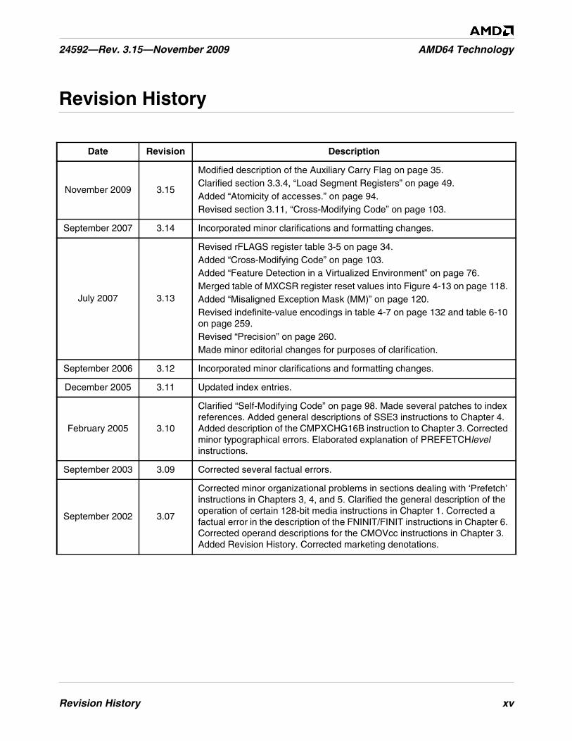
November 2009 3.15
Modified description of the Auxiliary Carry Flag on page 35.Clarified section 3.3.4, “Load Segment Registers” on page 49.Added “Atomicity of accesses.” on page 94.Revised section 3.11, “Cross-Modifying Code” on page 103.
September 2007 3.14 Incorporated minor clarifications and formatting changes.
July 2007 3.13
Revised rFLAGS register table 3-5 on page 34.Added “Cross-Modifying Code” on page 103.Added “Feature Detection in a Virtualized Environment” on page 76.Merged table of MXCSR register reset values into Figure 4-13 on page 118.Added “Misaligned Exception Mask (MM)” on page 120.Revised indefinite-value encodings in table 4-7 on page 132 and table 6-10on page 259.Revised “Precision” on page 260.Made minor editorial changes for purposes of clarification.
September 2006 3.12 Incorporated minor clarifications and formatting changes.
December 2005 3.11 Updated index entries.
February 2005 3.10
Clarified “Self-Modifying Code” on page 98. Made several patches to indexreferences. Added general descriptions of SSE3 instructions to Chapter 4.Added description of the CMPXCHG16B instruction to Chapter 3. Correctedminor typographical errors. Elaborated explanation of PREFETCHlevelinstructions.
September 2003 3.09 Corrected several factual errors.
September 2002 3.07
Corrected minor organizational problems in sections dealing with ‘Prefetch’instructions in Chapters 3, 4, and 5. Clarified the general description of theoperation of certain 128-bit media instructions in Chapter 1. Corrected afactual error in the description of the FNINIT/FINIT instructions in Chapter 6.Corrected operand descriptions for the CMOVcc instructions in Chapter 3.Added Revision History. Corrected marketing denotations.

xvi Revision History
AMD64 Technology 24592—Rev. 3.15—November 2009
Preface xvii
24592—Rev. 3.15—November 2009 AMD64 Technology
Preface
About This Book
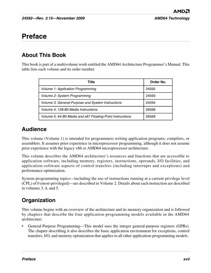
This book is part of a multivolume work entitled the AMD64 Architecture Programmer’s Manual. Thistable lists each volume and its order number.
Audience
This volume (Volume 1) is intended for programmers writing application programs, compilers, orassemblers. It assumes prior experience in microprocessor programming, although it does not assumeprior experience with the legacy x86 or AMD64 microprocessor architecture.
This volume describes the AMD64 architecture’s resources and functions that are accessible toapplication software, including memory, registers, instructions, operands, I/O facilities, andapplication-software aspects of control transfers (including interrupts and exceptions) andperformance optimization.
System-programming topics—including the use of instructions running at a current privilege level(CPL) of 0 (most-privileged)—are described in Volume 2. Details about each instruction are describedin volumes 3, 4, and 5.
Organization
This volume begins with an overview of the architecture and its memory organization and is followedby chapters that describe the four application-programming models available in the AMD64architecture:
• General-Purpose Programming—This model uses the integer general-purpose registers (GPRs).The chapter describing it also describes the basic application environment for exceptions, controltransfers, I/O, and memory optimization that applies to all other application-programming models.
Title Order No.
Volume 1: Application Programming 24592
Volume 2: System Programming 24593
Volume 3: General-Purpose and System Instructions 24594
Volume 4: 128-Bit Media Instructions 26568
Volume 5: 64-Bit Media and x87 Floating-Point Instructions 26569
xviii Preface
AMD64 Technology 24592—Rev. 3.15—November 2009
• 128-bit Media Programming—This model uses the 128-bit XMM registers and supports integerand floating-point operations on vector (packed) and scalar data types.
• 64-bit Media Programming—This model uses the 64-bit MMX™ registers and supports integerand floating-point operations on vector (packed) and scalar data types.
• x87 Floating-Point Programming—This model uses the 80-bit x87 registers and supports floating-point operations on scalar data types.
Definitions assumed throughout this volume are listed below. The index at the end of this volumecross-references topics within the volume. For other topics relating to the AMD64 architecture, see thetables of contents and indexes of the other volumes.
Definitions
Some of the following definitions assume a knowledge of the legacy x86 architecture. See “RelatedDocuments” on page xxviii for further information about the legacy x86 architecture.
Terms and Notation
1011b
A binary value—in this example, a 4-bit value.
F0EAh
A hexadecimal value—in this example a 2-byte value.
[1,2)
A range that includes the left-most value (in this case, 1) but excludes the right-most value (in thiscase, 2).
7–4
A bit range, from bit 7 to 4, inclusive. The high-order bit is shown first.
128-bit media instructions
Instructions that use the 128-bit XMM registers. These are a combination of the SSE and SSE2instruction sets.
64-bit media instructions
Instructions that use the 64-bit MMX registers. These are primarily a combination of MMX and3DNow!™ instruction sets, with some additional instructions from the SSE and SSE2 instructionsets.
16-bit mode
Legacy mode or compatibility mode in which a 16-bit address size is active. See legacy mode andcompatibility mode.
Preface xix
24592—Rev. 3.15—November 2009 AMD64 Technology
32-bit mode
Legacy mode or compatibility mode in which a 32-bit address size is active. See legacy mode andcompatibility mode.
64-bit mode
A submode of long mode. In 64-bit mode, the default address size is 64 bits and new features, suchas register extensions, are supported for system and application software.
#GP(0)
Notation indicating a general-protection exception (#GP) with error code of 0.
absolute
Said of a displacement that references the base of a code segment rather than an instruction pointer.Contrast with relative.
ASID
Address space identifier.
biased exponent
The sum of a floating-point value’s exponent and a constant bias for a particular floating-point datatype. The bias makes the range of the biased exponent always positive, which allows reciprocationwithout overflow.
byte
Eight bits.
clear
To write a bit value of 0. Compare set.
compatibility mode
A submode of long mode. In compatibility mode, the default address size is 32 bits, and legacy 16-bit and 32-bit applications run without modification.
commit
To irreversibly write, in program order, an instruction’s result to software-visible storage, such as aregister (including flags), the data cache, an internal write buffer, or memory.
CPL
Current privilege level.
CR0–CR4
A register range, from register CR0 through CR4, inclusive, with the low-order register first.
CR0.PE = 1
Notation indicating that the PE bit of the CR0 register has a value of 1.
xx Preface
AMD64 Technology 24592—Rev. 3.15—November 2009
direct
Referencing a memory location whose address is included in the instruction’s syntax as animmediate operand. The address may be an absolute or relative address. Compare indirect.
dirty data
Data held in the processor’s caches or internal buffers that is more recent than the copy held inmain memory.
displacement
A signed value that is added to the base of a segment (absolute addressing) or an instruction pointer(relative addressing). Same as offset.
doubleword
Two words, or four bytes, or 32 bits.
double quadword
Eight words, or 16 bytes, or 128 bits. Also called octword.
DS:rSI
The contents of a memory location whose segment address is in the DS register and whose offsetrelative to that segment is in the rSI register.
EFER.LME = 0
Notation indicating that the LME bit of the EFER register has a value of 0.
effective address size
The address size for the current instruction after accounting for the default address size and anyaddress-size override prefix.
effective operand size
The operand size for the current instruction after accounting for the default operand size and anyoperand-size override prefix.
element
See vector.
exception
An abnormal condition that occurs as the result of executing an instruction. The processor’sresponse to an exception depends on the type of the exception. For all exceptions except 128-bitmedia SIMD floating-point exceptions and x87 floating-point exceptions, control is transferred tothe handler (or service routine) for that exception, as defined by the exception’s vector. Forfloating-point exceptions defined by the IEEE 754 standard, there are both masked and unmaskedresponses. When unmasked, the exception handler is called, and when masked, a default responseis provided instead of calling the handler.
Preface xxi
24592—Rev. 3.15—November 2009 AMD64 Technology
FF /0
Notation indicating that FF is the first byte of an opcode, and a subopcode in the ModR/M byte hasa value of 0.
flush
An often ambiguous term meaning (1) writeback, if modified, and invalidate, as in “flush the cacheline,” or (2) invalidate, as in “flush the pipeline,” or (3) change a value, as in “flush to zero.”
GDT
Global descriptor table.
GIF
Global interrupt flag.
IDT
Interrupt descriptor table.
IGN
Ignore. Field is ignored.
indirect
Referencing a memory location whose address is in a register or other memory location. Theaddress may be an absolute or relative address. Compare direct.
IRB
The virtual-8086 mode interrupt-redirection bitmap.
IST
The long-mode interrupt-stack table.
IVT
The real-address mode interrupt-vector table.
LDT
Local descriptor table.
legacy x86
The legacy x86 architecture. See “Related Documents” on page xxviii for descriptions of thelegacy x86 architecture.
legacy mode
An operating mode of the AMD64 architecture in which existing 16-bit and 32-bit applications andoperating systems run without modification. A processor implementation of the AMD64architecture can run in either long mode or legacy mode. Legacy mode has three submodes, realmode, protected mode, and virtual-8086 mode.
xxii Preface
AMD64 Technology 24592—Rev. 3.15—November 2009
long mode
An operating mode unique to the AMD64 architecture. A processor implementation of theAMD64 architecture can run in either long mode or legacy mode. Long mode has two submodes,64-bit mode and compatibility mode.
lsb
Least-significant bit.
LSB
Least-significant byte.
main memory
Physical memory, such as RAM and ROM (but not cache memory) that is installed in a particularcomputer system.
mask
(1) A control bit that prevents the occurrence of a floating-point exception from invoking anexception-handling routine. (2) A field of bits used for a control purpose.
MBZ
Must be zero. If software attempts to set an MBZ bit to 1, a general-protection exception (#GP)occurs.
memory
Unless otherwise specified, main memory.
ModRM
A byte following an instruction opcode that specifies address calculation based on mode (Mod),register (R), and memory (M) variables.
moffset
A 16, 32, or 64-bit offset that specifies a memory operand directly, without using a ModRM or SIBbyte.
msb
Most-significant bit.
MSB
Most-significant byte.
multimedia instructions
A combination of 128-bit media instructions and 64-bit media instructions.
octword
Same as double quadword.
Preface xxiii
24592—Rev. 3.15—November 2009 AMD64 Technology
offset
Same as displacement.
overflow
The condition in which a floating-point number is larger in magnitude than the largest, finite,positive or negative number that can be represented in the data-type format being used.
packed
See vector.
PAE
Physical-address extensions.
physical memory
Actual memory, consisting of main memory and cache.
probe
A check for an address in a processor’s caches or internal buffers. External probes originateoutside the processor, and internal probes originate within the processor.
protected mode
A submode of legacy mode.
quadword
Four words, or eight bytes, or 64 bits.
RAZ
Read as zero (0), regardless of what is written.
real-address mode
See real mode.
real mode
A short name for real-address mode, a submode of legacy mode.
relative
Referencing with a displacement (also called offset) from an instruction pointer rather than thebase of a code segment. Contrast with absolute.
reserved
Fields marked as reserved may be used at some future time.
To preserve compatibility with future processors, reserved fields require special handling whenread or written by software.
Reserved fields may be further qualified as MBZ, RAZ, SBZ or IGN (see definitions).
xxiv Preface
AMD64 Technology 24592—Rev. 3.15—November 2009
Software must not depend on the state of a reserved field, nor upon the ability of such fields toreturn to a previously written state.
If a reserved field is not marked with one of the above qualifiers, software must not change the stateof that field; it must reload that field with the same values returned from a prior read.
REX
An instruction prefix that specifies a 64-bit operand size and provides access to additionalregisters.
RIP-relative addressing
Addressing relative to the 64-bit RIP instruction pointer.
scalar
An atomic value existing independently of any specification of location, direction, etc., as opposedto vectors.
set
To write a bit value of 1. Compare clear.
SIB
A byte following an instruction opcode that specifies address calculation based on scale (S), index(I), and base (B).
SIMD
Single instruction, multiple data. See vector.
SSE
Streaming SIMD extensions instruction set. See 128-bit media instructions and 64-bit mediainstructions.
SSE2
Extensions to the SSE instruction set. See 128-bit media instructions and 64-bit mediainstructions.
SSE3
Further extensions to the SSE instruction set. See 128-bit media instructions.
SSE4A
Further extensions to the SSE instruction set. See 128-bit media instructions.
sticky bit
A bit that is set or cleared by hardware and that remains in that state until explicitly changed bysoftware.
TOP
The x87 top-of-stack pointer.
Preface xxv
24592—Rev. 3.15—November 2009 AMD64 Technology
TSS
Task-state segment.
underflow
The condition in which a floating-point number is smaller in magnitude than the smallest nonzero,positive or negative number that can be represented in the data-type format being used.
vector
(1) A set of integer or floating-point values, called elements, that are packed into a single operand.Most of the 128-bit and 64-bit media instructions use vectors as operands. Vectors are also calledpacked or SIMD (single-instruction multiple-data) operands.
(2) An index into an interrupt descriptor table (IDT), used to access exception handlers. Compareexception.
virtual-8086 mode
A submode of legacy mode.
VMCB
Virtual machine control block.
VMM
Virtual machine monitor.
word
Two bytes, or 16 bits.
x86
See legacy x86.
Registers
In the following list of registers, the names are used to refer either to a given register or to the contentsof that register:
AH–DH
The high 8-bit AH, BH, CH, and DH registers. Compare AL–DL.
AL–DL
The low 8-bit AL, BL, CL, and DL registers. Compare AH–DH.
AL–r15B
The low 8-bit AL, BL, CL, DL, SIL, DIL, BPL, SPL, and R8B–R15B registers, available in 64-bitmode.
BP
Base pointer register.
xxvi Preface
AMD64 Technology 24592—Rev. 3.15—November 2009
CRn
Control register number n.
CS
Code segment register.
eAX–eSP
The 16-bit AX, BX, CX, DX, DI, SI, BP, and SP registers or the 32-bit EAX, EBX, ECX, EDX,EDI, ESI, EBP, and ESP registers. Compare rAX–rSP.
EFER
Extended features enable register.
eFLAGS
16-bit or 32-bit flags register. Compare rFLAGS.
EFLAGS
32-bit (extended) flags register.
eIP
16-bit or 32-bit instruction-pointer register. Compare rIP.
EIP
32-bit (extended) instruction-pointer register.
FLAGS
16-bit flags register.
GDTR
Global descriptor table register.
GPRs
General-purpose registers. For the 16-bit data size, these are AX, BX, CX, DX, DI, SI, BP, and SP.For the 32-bit data size, these are EAX, EBX, ECX, EDX, EDI, ESI, EBP, and ESP. For the 64-bitdata size, these include RAX, RBX, RCX, RDX, RDI, RSI, RBP, RSP, and R8–R15.
IDTR
Interrupt descriptor table register.
IP
16-bit instruction-pointer register.
LDTR
Local descriptor table register.
Preface xxvii
24592—Rev. 3.15—November 2009 AMD64 Technology
MSR
Model-specific register.
r8–r15
The 8-bit R8B–R15B registers, or the 16-bit R8W–R15W registers, or the 32-bit R8D–R15Dregisters, or the 64-bit R8–R15 registers.
rAX–rSP
The 16-bit AX, BX, CX, DX, DI, SI, BP, and SP registers, or the 32-bit EAX, EBX, ECX, EDX,EDI, ESI, EBP, and ESP registers, or the 64-bit RAX, RBX, RCX, RDX, RDI, RSI, RBP, and RSPregisters. Replace the placeholder r with nothing for 16-bit size, “E” for 32-bit size, or “R” for 64-bit size.
RAX
64-bit version of the EAX register.
RBP
64-bit version of the EBP register.
RBX
64-bit version of the EBX register.
RCX
64-bit version of the ECX register.
RDI
64-bit version of the EDI register.
RDX
64-bit version of the EDX register.
rFLAGS
16-bit, 32-bit, or 64-bit flags register. Compare RFLAGS.
RFLAGS
64-bit flags register. Compare rFLAGS.
rIP
16-bit, 32-bit, or 64-bit instruction-pointer register. Compare RIP.
RIP
64-bit instruction-pointer register.
RSI
64-bit version of the ESI register.
xxviii Preface
AMD64 Technology 24592—Rev. 3.15—November 2009
RSP
64-bit version of the ESP register.
SP
Stack pointer register.
SS
Stack segment register.
TPR
Task priority register (CR8), a new register introduced in the AMD64 architecture to speedinterrupt management.
TR
Task register.
Endian Order
The x86 and AMD64 architectures address memory using little-endian byte-ordering. Multibytevalues are stored with their least-significant byte at the lowest byte address, and they are illustratedwith their least significant byte at the right side. Strings are illustrated in reverse order, because theaddresses of their bytes increase from right to left.
Related Documents• Peter Abel, IBM PC Assembly Language and Programming, Prentice-Hall, Englewood Cliffs, NJ,
1995.
• Rakesh Agarwal, 80x86 Architecture & Programming: Volume II, Prentice-Hall, EnglewoodCliffs, NJ, 1991.
• AMD data sheets and application notes for particular hardware implementations of the AMD64architecture.
• AMD, AMD-K6® MMX™ Enhanced Processor Multimedia Technology, Sunnyvale, CA, 2000.
• AMD, 3DNow!™ Technology Manual, Sunnyvale, CA, 2000.
• AMD, AMD Extensions to the 3DNow!™ and MMX™ Instruction Sets, Sunnyvale, CA, 2000.
• Don Anderson and Tom Shanley, Pentium® Processor System Architecture, Addison-Wesley, NewYork, 1995.
• Nabajyoti Barkakati and Randall Hyde, Microsoft Macro Assembler Bible, Sams, Carmel, Indiana,1992.
• Barry B. Brey, 8086/8088, 80286, 80386, and 80486 Assembly Language Programming,Macmillan Publishing Co., New York, 1994.
• Barry B. Brey, Programming the 80286, 80386, 80486, and Pentium Based Personal Computer,Prentice-Hall, Englewood Cliffs, NJ, 1995.
Preface xxix
24592—Rev. 3.15—November 2009 AMD64 Technology
• Ralf Brown and Jim Kyle, PC Interrupts, Addison-Wesley, New York, 1994.
• Penn Brumm and Don Brumm, 80386/80486 Assembly Language Programming, WindcrestMcGraw-Hill, 1993.
• Geoff Chappell, DOS Internals, Addison-Wesley, New York, 1994.
• Chips and Technologies, Inc. Super386 DX Programmer’s Reference Manual, Chips andTechnologies, Inc., San Jose, 1992.
• John Crawford and Patrick Gelsinger, Programming the 80386, Sybex, San Francisco, 1987.
• Cyrix Corporation, 5x86 Processor BIOS Writer's Guide, Cyrix Corporation, Richardson, TX,1995.
• Cyrix Corporation, M1 Processor Data Book, Cyrix Corporation, Richardson, TX, 1996.
• Cyrix Corporation, MX Processor MMX Extension Opcode Table, Cyrix Corporation, Richardson,TX, 1996.
• Cyrix Corporation, MX Processor Data Book, Cyrix Corporation, Richardson, TX, 1997.
• Ray Duncan, Extending DOS: A Programmer's Guide to Protected-Mode DOS, Addison Wesley,NY, 1991.
• William B. Giles, Assembly Language Programming for the Intel 80xxx Family, Macmillan, NewYork, 1991.
• Frank van Gilluwe, The Undocumented PC, Addison-Wesley, New York, 1994.
• John L. Hennessy and David A. Patterson, Computer Architecture, Morgan Kaufmann Publishers,San Mateo, CA, 1996.
• Thom Hogan, The Programmer’s PC Sourcebook, Microsoft Press, Redmond, WA, 1991.
• Hal Katircioglu, Inside the 486, Pentium®, and Pentium Pro, Peer-to-Peer Communications,Menlo Park, CA, 1997.
• IBM Corporation, 486SLC Microprocessor Data Sheet, IBM Corporation, Essex Junction, VT,1993.
• IBM Corporation, 486SLC2 Microprocessor Data Sheet, IBM Corporation, Essex Junction, VT,1993.
• IBM Corporation, 80486DX2 Processor Floating Point Instructions, IBM Corporation, EssexJunction, VT, 1995.
• IBM Corporation, 80486DX2 Processor BIOS Writer's Guide, IBM Corporation, Essex Junction,VT, 1995.
• IBM Corporation, Blue Lightning 486DX2 Data Book, IBM Corporation, Essex Junction, VT,1994.
• Institute of Electrical and Electronics Engineers, IEEE Standard for Binary Floating-PointArithmetic, ANSI/IEEE Std 754-1985.
• Institute of Electrical and Electronics Engineers, IEEE Standard for Radix-Independent Floating-Point Arithmetic, ANSI/IEEE Std 854-1987.
xxx Preface
AMD64 Technology 24592—Rev. 3.15—November 2009
• Muhammad Ali Mazidi and Janice Gillispie Mazidi, 80X86 IBM PC and Compatible Computers,Prentice-Hall, Englewood Cliffs, NJ, 1997.
• Hans-Peter Messmer, The Indispensable Pentium Book, Addison-Wesley, New York, 1995.
• Karen Miller, An Assembly Language Introduction to Computer Architecture: Using the IntelPentium®, Oxford University Press, New York, 1999.
• Stephen Morse, Eric Isaacson, and Douglas Albert, The 80386/387 Architecture, John Wiley &Sons, New York, 1987.
• NexGen Inc., Nx586 Processor Data Book, NexGen Inc., Milpitas, CA, 1993.
• NexGen Inc., Nx686 Processor Data Book, NexGen Inc., Milpitas, CA, 1994.
• Bipin Patwardhan, Introduction to the Streaming SIMD Extensions in the Pentium® III,www.x86.org/articles/sse_pt1/ simd1.htm, June, 2000.
• Peter Norton, Peter Aitken, and Richard Wilton, PC Programmer’s Bible, Microsoft® Press,Redmond, WA, 1993.
• PharLap 386|ASM Reference Manual, Pharlap, Cambridge MA, 1993.
• PharLap TNT DOS-Extender Reference Manual, Pharlap, Cambridge MA, 1995.
• Sen-Cuo Ro and Sheau-Chuen Her, i386/i486 Advanced Programming, Van Nostrand Reinhold,New York, 1993.
• Jeffrey P. Royer, Introduction to Protected Mode Programming, course materials for an onsiteclass, 1992.
• Tom Shanley, Protected Mode System Architecture, Addison Wesley, NY, 1996.
• SGS-Thomson Corporation, 80486DX Processor SMM Programming Manual, SGS-ThomsonCorporation, 1995.
• Walter A. Triebel, The 80386DX Microprocessor, Prentice-Hall, Englewood Cliffs, NJ, 1992.
• John Wharton, The Complete x86, MicroDesign Resources, Sebastopol, California, 1994.
• Web sites and newsgroups:
- www.amd.com
- news.comp.arch
- news.comp.lang.asm.x86
- news.intel.microprocessors
- news.microsoft
Overview of the AMD64 Architecture 1
24592—Rev. 3.15—November 2009 AMD64 Technology
1 Overview of the AMD64 Architecture
1.1 Introduction
The AMD64 architecture is a simple yet powerful 64-bit, backward-compatible extension of theindustry-standard (legacy) x86 architecture. It adds 64-bit addressing and expands register resources tosupport higher performance for recompiled 64-bit programs, while supporting legacy 16-bit and 32-bitapplications and operating systems without modification or recompilation. It is the architectural basison which new processors can provide seamless, high-performance support for both the vast body ofexisting software and 64-bit software required for higher-performance applications.
The need for a 64-bit x86 architecture is driven by applications that address large amounts of virtualand physical memory, such as high-performance servers, database management systems, and CADtools. These applications benefit from both 64-bit addresses and an increased number of registers. Thesmall number of registers available in the legacy x86 architecture limits performance in computation-intensive applications. Increasing the number of registers provides a performance boost to many suchapplications.
1.1.1 AMD64 Features
The AMD64 architecture introduces these features:
• Register Extensions (see Figure 1-1 on page 2):
- 8 additional general-purpose registers (GPRs).
- All 16 GPRs are 64 bits wide.
- 8 128-bit XMM registers.
- Uniform byte-register addressing for all GPRs.
- An instruction prefix (REX) accesses the extended registers.
• Long Mode (see Table 1-1 on page 2):
- Up to 64 bits of virtual address.
- 64-bit instruction pointer (RIP).
- Instruction-pointer-relative data-addressing mode.
- Flat address space.
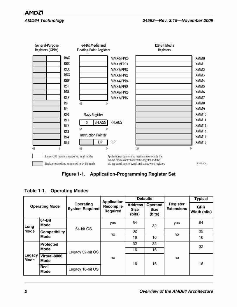
2 Overview of the AMD64 Architecture
AMD64 Technology 24592—Rev. 3.15—November 2009
Figure 1-1. Application-Programming Register Set
Table 1-1. Operating Modes
Operating ModeOperating
System Required
ApplicationRecompileRequired
DefaultsRegister
Extensions
Typical
AddressSize(bits)
OperandSize(bits)
GPRWidth (bits)
LongMode
64-BitMode
64-bit OS
yes 6432
yes 64
CompatibilityMode
no32
no32
16 16 16
LegacyMode
ProtectedMode
Legacy 32-bit OSno
32 32
no
3216 16
Virtual-8086Mode
16 16 16RealMode
Legacy 16-bit OS
513-101.eps
Flags Register
Instruction Pointer
General-PurposeRegisters (GPRs)
128-Bit MediaRegisters
64-Bit Media andFloating-Point Registers
Legacy x86 registers, supported in all modes Application-programming registers also include the128-bit media control-and-status register and thex87 tag-word, control-word, and status-word registers
63 0 63 0
63 0
127 0
63 0
Register extensions, supported in 64-bit mode
RAXRBXRCXRDXRBPRSIRDIRSPR8R9R10R11R12R13R14R15
MMX0/FPR0MMX1/FPR1MMX2/FPR2MMX3/FPR3MMX4/FPR4MMX5/FPR5MMX6/FPR6MMX7/FPR7
XMM0XMM1XMM2XMM3XMM4XMM5XMM6XMM7XMM8XMM9XMM10XMM11XMM12XMM13XMM14XMM15
0 RFLAGS
RIP
EFLAGS
EIP
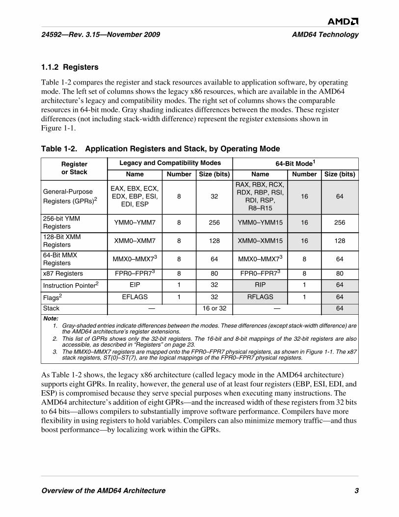
Overview of the AMD64 Architecture 3
24592—Rev. 3.15—November 2009 AMD64 Technology
1.1.2 Registers
Table 1-2 compares the register and stack resources available to application software, by operatingmode. The left set of columns shows the legacy x86 resources, which are available in the AMD64architecture’s legacy and compatibility modes. The right set of columns shows the comparableresources in 64-bit mode. Gray shading indicates differences between the modes. These registerdifferences (not including stack-width difference) represent the register extensions shown inFigure 1-1.
As Table 1-2 shows, the legacy x86 architecture (called legacy mode in the AMD64 architecture)supports eight GPRs. In reality, however, the general use of at least four registers (EBP, ESI, EDI, andESP) is compromised because they serve special purposes when executing many instructions. TheAMD64 architecture’s addition of eight GPRs—and the increased width of these registers from 32 bitsto 64 bits—allows compilers to substantially improve software performance. Compilers have moreflexibility in using registers to hold variables. Compilers can also minimize memory traffic—and thusboost performance—by localizing work within the GPRs.
Table 1-2. Application Registers and Stack, by Operating Mode
Registeror Stack
Legacy and Compatibility Modes 64-Bit Mode1
Name Number Size (bits) Name Number Size (bits)
General-Purpose
Registers (GPRs)2
EAX, EBX, ECX,EDX, EBP, ESI,
EDI, ESP8 32
RAX, RBX, RCX,RDX, RBP, RSI,
RDI, RSP,R8–R15
16 64
256-bit YMMRegisters
YMM0–YMM7 8 256 YMM0–YMM15 16 256
128-Bit XMMRegisters
XMM0–XMM7 8 128 XMM0–XMM15 16 128
64-Bit MMXRegisters
MMX0–MMX73 8 64 MMX0–MMX73 8 64
x87 Registers FPR0–FPR73 8 80 FPR0–FPR73 8 80
Instruction Pointer2 EIP 1 32 RIP 1 64
Flags2 EFLAGS 1 32 RFLAGS 1 64
Stack — 16 or 32 — 64
Note:1. Gray-shaded entries indicate differences between the modes. These differences (except stack-width difference) are
the AMD64 architecture’s register extensions.2. This list of GPRs shows only the 32-bit registers. The 16-bit and 8-bit mappings of the 32-bit registers are also
accessible, as described in “Registers” on page 23.3. The MMX0–MMX7 registers are mapped onto the FPR0–FPR7 physical registers, as shown in Figure 1-1. The x87
stack registers, ST(0)–ST(7), are the logical mappings of the FPR0–FPR7 physical registers.

4 Overview of the AMD64 Architecture
AMD64 Technology 24592—Rev. 3.15—November 2009
1.1.3 Instruction Set
The AMD64 architecture supports the full legacy x86 instruction set, with additional instructions tosupport long mode (see Table 1-1 on page 2 for a summary of operating modes). The application-programming instructions are organized into three subsets, as follows:
• General-Purpose Instructions—These are the basic x86 integer instructions used in virtually allprograms. Most of these instructions load, store, or operate on data located in the general-purposeregisters (GPRs) or memory. Some of the instructions alter sequential program flow by branchingto other program locations.
• 128-Bit and 256-bit Media Instructions—These are the streaming SIMD extension (SSE, SSE2,SSE3, SSSE3, SSE4, SSE4A, AVX) instructions that load, store, or operate on data locatedprimarily in the 128-bit XMM registers. They perform integer and floating-point operations onvector (packed) and scalar data types. Because the vector instructions can independently andsimultaneously perform a single operation on multiple sets of data, they are called single-instruction, multiple-data (SIMD) instructions. They are useful for high-performance media andscientific applications that operate on blocks of data.
• 64-Bit Media Instructions—These are the multimedia extension (MMX™ technology) and AMD3DNow!™ technology instructions. These instructions load, store, or operate on data locatedprimarily in the 64-bit MMX registers. Like their 128-bit counterparts, described above, theyperform integer and floating-point operations on vector (packed) and scalar data types. Thus, theyare also SIMD instructions and are useful in media applications that operate on blocks of data.AMD no longer recommends the use of 3DNow! instructions, which have been superceded bytheir more efficient 128-bit media counterparts. Relevant recommendations are provided inChapter 5, “64-Bit Media Programming” on page 193, and in the AMD64 Programmer’s ManualVolume 4: 64-Bit Media and x87 Floating-Point Instructions.
• x87 Floating-Point Instructions—These are the floating-point instructions used in legacy x87applications. They load, store, or operate on data located in the x87 registers.
Some of these application-programming instructions bridge two or more of the above subsets. Forexample, there are instructions that move data between the general-purpose registers and the XMM orMMX registers, and many of the integer vector (packed) instructions can operate on either XMM orMMX registers, although not simultaneously. If instructions bridge two or more subsets, theirdescriptions are repeated in all subsets to which they apply.
1.1.4 Media Instructions
Media applications—such as image processing, music synthesis, speech recognition, full-motionvideo, and 3D graphics rendering—share certain characteristics:
• They process large amounts of data.
• They often perform the same sequence of operations repeatedly across the data.
• The data are often represented as small quantities, such as 8 bits for pixel values, 16 bits for audiosamples, and 32 bits for object coordinates in floating-point format.
Overview of the AMD64 Architecture 5
24592—Rev. 3.15—November 2009 AMD64 Technology
The 128-bit and 64-bit media instructions are designed to accelerate these applications. Theinstructions use a form of vector (or packed) parallel processing known as single-instruction, multipledata (SIMD) processing. This vector technology has the following characteristics:
• A single register can hold multiple independent pieces of data. For example, a single 128-bit XMMregister can hold 16 8-bit integer data elements, or four 32-bit single-precision floating-point dataelements.
• The vector instructions can operate on all data elements in a register, independently andsimultaneously. For example, a PADDB instruction operating on byte elements of two vectoroperands in 128-bit XMM registers performs 16 simultaneous additions and returns 16independent results in a single operation.
128-bit and 64-bit media instructions take SIMD vector technology a step further by including specialinstructions that perform operations commonly found in media applications. For example, a graphicsapplication that adds the brightness values of two pixels must prevent the add operation from wrappingaround to a small value if the result overflows the destination register, because an overflow result canproduce unexpected effects such as a dark pixel where a bright one is expected. The 128-bit and 64-bitmedia instructions include saturating-arithmetic instructions to simplify this type of operation. Aresult that otherwise would wrap around due to overflow or underflow is instead forced to saturate atthe largest or smallest value that can be represented in the destination register.
1.1.5 Floating-Point Instructions
The AMD64 architecture provides three floating-point instruction subsets, using three distinct registersets:
• 128-Bit Media Instructions support 32-bit single-precision and 64-bit double-precision floating-point operations, in addition to integer operations. Operations on both vector data and scalar dataare supported, with a dedicated floating-point exception-reporting mechanism. These floating-point operations comply with the IEEE-754 standard.
• 64-Bit Media Instructions (the subset of 3DNow! technology instructions) support single-precision floating-point operations. Operations on both vector data and scalar data are supported,but these instructions do not support floating-point exception reporting.
• x87 Floating-Point Instructions support single-precision, double-precision, and 80-bit extended-precision floating-point operations. Only scalar data are supported, with a dedicated floating-pointexception-reporting mechanism. The x87 floating-point instructions contain special instructionsfor performing trigonometric and logarithmic transcendental operations. The single-precision anddouble-precision floating-point operations comply with the IEEE-754 standard.
Maximum floating-point performance can be achieved using the 128-bit media instructions. One ofthese vector instructions can support up to four single-precision (or two double-precision) operationsin parallel. In 64-bit mode, the AMD64 architecture doubles the number of legacy XMM registersfrom 8 to 16.
Applications gain additional benefits using the 64-bit media and x87 instructions. The separate registersets supported by these instructions relieve pressure on the XMM registers available to the 128-bit
6 Overview of the AMD64 Architecture
AMD64 Technology 24592—Rev. 3.15—November 2009
media instructions. This provides application programs with three distinct sets of floating-pointregisters. In addition, certain high-end implementations of the AMD64 architecture may support 128-bit media, 64-bit media, and x87 instructions with separate execution units.
1.2 Modes of Operation
Table 1-1 on page 2 summarizes the modes of operation supported by the AMD64 architecture. Inmost cases, the default address and operand sizes can be overridden with instruction prefixes. Theregister extensions shown in the second-from-right column of Table 1-1 are those illustrated inFigure 1-1 on page 2.
1.2.1 Long Mode
Long mode is an extension of legacy protected mode. Long mode consists of two submodes: 64-bitmode and compatibility mode. 64-bit mode supports all of the features and register extensions of theAMD64 architecture. Compatibility mode supports binary compatibility with existing 16-bit and 32-bit applications. Long mode does not support legacy real mode or legacy virtual-8086 mode, and itdoes not support hardware task switching.
Throughout this document, references to long mode refer to both 64-bit mode and compatibility mode.If a function is specific to either of these submodes, then the name of the specific submode is usedinstead of the name long mode.
1.2.2 64-Bit Mode
64-bit mode—a submode of long mode—supports the full range of 64-bit virtual-addressing andregister-extension features. This mode is enabled by the operating system on an individual code-segment basis. Because 64-bit mode supports a 64-bit virtual-address space, it requires a 64-bitoperating system and tool chain. Existing application binaries can run without recompilation incompatibility mode, under an operating system that runs in 64-bit mode, or the applications can also berecompiled to run in 64-bit mode.
Addressing features include a 64-bit instruction pointer (RIP) and an RIP-relative data-addressingmode. This mode accommodates modern operating systems by supporting only a flat address space,with single code, data, and stack space.
Register Extensions. 64-bit mode implements register extensions through a group of instructionprefixes, called REX prefixes. These extensions add eight GPRs (R8–R15), widen all GPRs to 64 bits,and add eight 128-bit XMM registers (XMM8–XMM15).
The REX instruction prefixes also provide a byte-register capability that makes the low byte of any ofthe sixteen GPRs available for byte operations. This results in a uniform set of byte, word, doubleword,and quadword registers that is better suited to compiler register-allocation.
64-Bit Addresses and Operands. In 64-bit mode, the default virtual-address size is 64 bits(implementations can have fewer). The default operand size for most instructions is 32 bits. For most
Overview of the AMD64 Architecture 7
24592—Rev. 3.15—November 2009 AMD64 Technology
instructions, these defaults can be overridden on an instruction-by-instruction basis using instructionprefixes. REX prefixes specify the 64-bit operand size and register extensions.
RIP-Relative Data Addressing. 64-bit mode supports data addressing relative to the 64-bitinstruction pointer (RIP). The legacy x86 architecture supports IP-relative addressing only in control-transfer instructions. RIP-relative addressing improves the efficiency of position-independent codeand code that addresses global data.
Opcodes. A few instruction opcodes and prefix bytes are redefined to allow register extensions and64-bit addressing. These differences are described in “General-Purpose Instructions in 64-Bit Mode”in Volume 3 and “Differences Between Long Mode and Legacy Mode” in Volume 3.
1.2.3 Compatibility Mode
Compatibility mode—the second submode of long mode—allows 64-bit operating systems to runexisting 16-bit and 32-bit x86 applications. These legacy applications run in compatibility modewithout recompilation.
Applications running in compatibility mode use 32-bit or 16-bit addressing and can access the first4GB of virtual-address space. Legacy x86 instruction prefixes toggle between 16-bit and 32-bitaddress and operand sizes.
As with 64-bit mode, compatibility mode is enabled by the operating system on an individual code-segment basis. Unlike 64-bit mode, however, x86 segmentation functions the same as in the legacy x86architecture, using 16-bit or 32-bit protected-mode semantics. From the application viewpoint,compatibility mode looks like the legacy x86 protected-mode environment. From the operating-system viewpoint, however, address translation, interrupt and exception handling, and system datastructures use the 64-bit long-mode mechanisms.
1.2.4 Legacy Mode
Legacy mode preserves binary compatibility not only with existing 16-bit and 32-bit applications butalso with existing 16-bit and 32-bit operating systems. Legacy mode consists of the following threesubmodes:
• Protected Mode—Protected mode supports 16-bit and 32-bit programs with memorysegmentation, optional paging, and privilege-checking. Programs running in protected mode canaccess up to 4GB of memory space.
• Virtual-8086 Mode—Virtual-8086 mode supports 16-bit real-mode programs running as tasksunder protected mode. It uses a simple form of memory segmentation, optional paging, and limitedprotection-checking. Programs running in virtual-8086 mode can access up to 1MB of memoryspace.
• Real Mode—Real mode supports 16-bit programs using simple register-based memorysegmentation. It does not support paging or protection-checking. Programs running in real modecan access up to 1MB of memory space.

8 Overview of the AMD64 Architecture
AMD64 Technology 24592—Rev. 3.15—November 2009
Legacy mode is compatible with existing 32-bit processor implementations of the x86 architecture.Processors that implement the AMD64 architecture boot in legacy real mode, just like processors thatimplement the legacy x86 architecture.
Throughout this document, references to legacy mode refer to all three submodes—protected mode,virtual-8086 mode, and real mode. If a function is specific to either of these submodes, then the nameof the specific submode is used instead of the name legacy mode.
Memory Model 9
24592—Rev. 3.15—November 2009 AMD64 Technology
2 Memory Model
This chapter describes the memory characteristics that apply to application software in the variousoperating modes of the AMD64 architecture. These characteristics apply to all instructions in thearchitecture. Several additional system-level details about memory and cache management aredescribed in Volume 2.
2.1 Memory Organization
2.1.1 Virtual Memory
Virtual memory consists of the entire address space available to programs. It is a large linear-addressspace that is translated by a combination of hardware and operating-system software to a smallerphysical-address space, parts of which are located in memory and parts on disk or other externalstorage media.
Figure 2-1 on page 10 shows how the virtual-memory space is treated in the two submodes of longmode:
• 64-bit mode—This mode uses a flat segmentation model of virtual memory. The 64-bit virtual-memory space is treated as a single, flat (unsegmented) address space. Program addresses accesslocations that can be anywhere in the linear 64-bit address space. The operating system can useseparate selectors for code, stack, and data segments for memory-protection purposes, but the baseaddress of all these segments is always 0. (For an exception to this general rule, see “FS and GS asBase of Address Calculation” on page 17.)
• Compatibility mode—This mode uses a protected, multi-segment model of virtual memory, just asin legacy protected mode. The 32-bit virtual-memory space is treated as a segmented set of addressspaces for code, stack, and data segments, each with its own base address and protectionparameters. A segmented space is specified by adding a segment selector to an address.
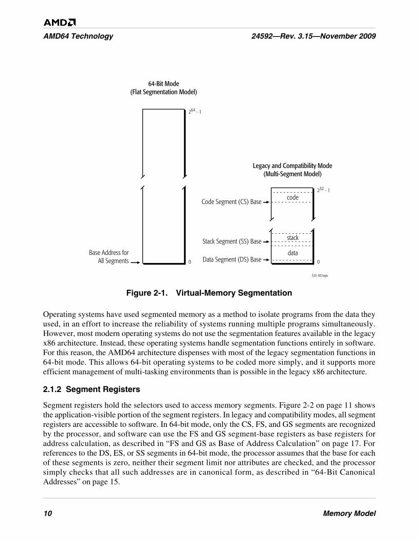
10 Memory Model
AMD64 Technology 24592—Rev. 3.15—November 2009
Figure 2-1. Virtual-Memory Segmentation
Operating systems have used segmented memory as a method to isolate programs from the data theyused, in an effort to increase the reliability of systems running multiple programs simultaneously.However, most modern operating systems do not use the segmentation features available in the legacyx86 architecture. Instead, these operating systems handle segmentation functions entirely in software.For this reason, the AMD64 architecture dispenses with most of the legacy segmentation functions in64-bit mode. This allows 64-bit operating systems to be coded more simply, and it supports moreefficient management of multi-tasking environments than is possible in the legacy x86 architecture.
2.1.2 Segment Registers
Segment registers hold the selectors used to access memory segments. Figure 2-2 on page 11 showsthe application-visible portion of the segment registers. In legacy and compatibility modes, all segmentregisters are accessible to software. In 64-bit mode, only the CS, FS, and GS segments are recognizedby the processor, and software can use the FS and GS segment-base registers as base registers foraddress calculation, as described in “FS and GS as Base of Address Calculation” on page 17. Forreferences to the DS, ES, or SS segments in 64-bit mode, the processor assumes that the base for eachof these segments is zero, neither their segment limit nor attributes are checked, and the processorsimply checks that all such addresses are in canonical form, as described in “64-Bit CanonicalAddresses” on page 15.
513-107.eps
264 - 1
0
Base Address forAll Segments
Code Segment (CS) Base
Stack Segment (SS) Base
Data Segment (DS) Base
64-Bit Mode(Flat Segmentation Model)
Legacy and Compatibility Mode(Multi-Segment Model)
232 - 1
0
data
code
stack

Memory Model 11
24592—Rev. 3.15—November 2009 AMD64 Technology
Figure 2-2. Segment Registers
For details on segmentation and the segment registers, see “Segmented Virtual Memory” in Volume 2.
2.1.3 Physical Memory
Physical memory is the installed memory (excluding cache memory) in a particular computer systemthat can be accessed through the processor’s bus interface. The maximum size of the physical memoryspace is determined by the number of address bits on the bus interface. In a virtual-memory system, thelarge virtual-address space (also called linear-address space) is translated to a smaller physical-address space by a combination of segmentation and paging hardware and software.
Segmentation is illustrated in Figure 2-1 on page 10. Paging is a mechanism for translating linear(virtual) addresses into fixed-size blocks called pages, which the operating system can move, asneeded, between memory and external storage media (typically disk). The AMD64 architecturesupports an expanded version of the legacy x86 paging mechanism, one that is able to translate the full64-bit virtual-address space into the physical-address space supported by the particularimplementation.
2.1.4 Memory Management
Memory management strategies translate addresses generated by programs into addresses in physicalmemory using segmentation and/or paging. Memory management is not visible to applicationprograms. It is handled by the operating system and processor hardware. The following descriptiongives a very brief overview of these functions. Details are given in “System-Management Instructions”in Volume 2.
513-312.eps
15 0
ES
FS
GS
SS
CS
DS
15 0
FS(Base only)
GS(Base only)
CS(Attributes only)
Legacy Mode andCompatibility Mode
64-BitMode
ignored
ignored
ignored
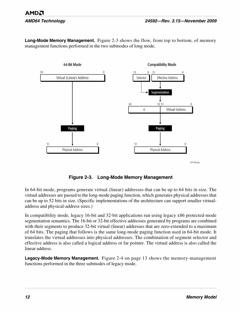
12 Memory Model
AMD64 Technology 24592—Rev. 3.15—November 2009
Long-Mode Memory Management. Figure 2-3 shows the flow, from top to bottom, of memorymanagement functions performed in the two submodes of long mode.
Figure 2-3. Long-Mode Memory Management
In 64-bit mode, programs generate virtual (linear) addresses that can be up to 64 bits in size. Thevirtual addresses are passed to the long-mode paging function, which generates physical addresses thatcan be up to 52 bits in size. (Specific implementations of the architecture can support smaller virtual-address and physical-address sizes.)
In compatibility mode, legacy 16-bit and 32-bit applications run using legacy x86 protected-modesegmentation semantics. The 16-bit or 32-bit effective addresses generated by programs are combinedwith their segments to produce 32-bit virtual (linear) addresses that are zero-extended to a maximumof 64 bits. The paging that follows is the same long-mode paging function used in 64-bit mode. Ittranslates the virtual addresses into physical addresses. The combination of segment selector andeffective address is also called a logical address or far pointer. The virtual address is also called thelinear address.
Legacy-Mode Memory Management. Figure 2-4 on page 13 shows the memory-managementfunctions performed in the three submodes of legacy mode.
513-184.eps
051
64-Bit Mode
63 0
Paging
051
Compatibility Mode
Segmentation
Paging
031015
Physical Address
Virtual (Linear) Address
Physical Address
Effective AddressSelector
0313263
Virtual Address0
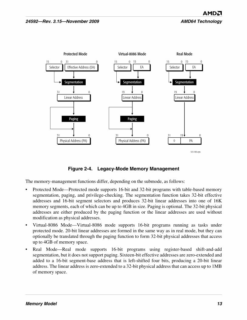
Memory Model 13
24592—Rev. 3.15—November 2009 AMD64 Technology
Figure 2-4. Legacy-Mode Memory Management
The memory-management functions differ, depending on the submode, as follows:
• Protected Mode—Protected mode supports 16-bit and 32-bit programs with table-based memorysegmentation, paging, and privilege-checking. The segmentation function takes 32-bit effectiveaddresses and 16-bit segment selectors and produces 32-bit linear addresses into one of 16Kmemory segments, each of which can be up to 4GB in size. Paging is optional. The 32-bit physicaladdresses are either produced by the paging function or the linear addresses are used withoutmodification as physical addresses.
• Virtual-8086 Mode—Virtual-8086 mode supports 16-bit programs running as tasks underprotected mode. 20-bit linear addresses are formed in the same way as in real mode, but they canoptionally be translated through the paging function to form 32-bit physical addresses that accessup to 4GB of memory space.
• Real Mode—Real mode supports 16-bit programs using register-based shift-and-addsegmentation, but it does not support paging. Sixteen-bit effective addresses are zero-extended andadded to a 16-bit segment-base address that is left-shifted four bits, producing a 20-bit linearaddress. The linear address is zero-extended to a 32-bit physical address that can access up to 1MBof memory space.
513-185.eps
031
Protected Mode
031
Paging
Physical Address (PA)
Linear Address
Virtual-8086 Mode
019
031
Paging
Linear Address
Physical Address (PA)
Real Mode
019
19 031
Linear Address
0 PA
Segmentation
031015
Effective Address (EA)Selector
015
EA
Segmentation
015
Selector
015
EA
Segmentation
015
Selector
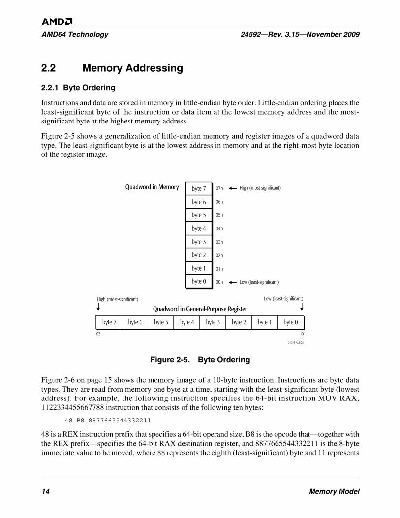
14 Memory Model
AMD64 Technology 24592—Rev. 3.15—November 2009
2.2 Memory Addressing
2.2.1 Byte Ordering
Instructions and data are stored in memory in little-endian byte order. Little-endian ordering places theleast-significant byte of the instruction or data item at the lowest memory address and the most-significant byte at the highest memory address.
Figure 2-5 shows a generalization of little-endian memory and register images of a quadword datatype. The least-significant byte is at the lowest address in memory and at the right-most byte locationof the register image.
Figure 2-5. Byte Ordering
Figure 2-6 on page 15 shows the memory image of a 10-byte instruction. Instructions are byte datatypes. They are read from memory one byte at a time, starting with the least-significant byte (lowestaddress). For example, the following instruction specifies the 64-bit instruction MOV RAX,1122334455667788 instruction that consists of the following ten bytes:
48 B8 8877665544332211
48 is a REX instruction prefix that specifies a 64-bit operand size, B8 is the opcode that—together withthe REX prefix—specifies the 64-bit RAX destination register, and 8877665544332211 is the 8-byteimmediate value to be moved, where 88 represents the eighth (least-significant) byte and 11 represents
513-116.eps
Quadword in Memory
Quadword in General-Purpose Register
00hbyte 0
01hbyte 1
02hbyte 2
03hbyte 3
04hbyte 4
05hbyte 5
06hbyte 6
07hbyte 7
063
byte 0byte 1byte 2byte 3byte 4byte 5byte 6byte 7
High (most-significant) Low (least-significant)
High (most-significant)
Low (least-significant)
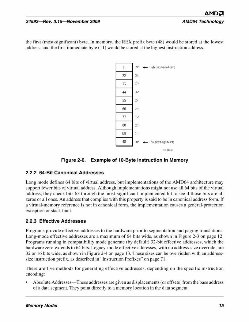
Memory Model 15
24592—Rev. 3.15—November 2009 AMD64 Technology
the first (most-significant) byte. In memory, the REX prefix byte (48) would be stored at the lowestaddress, and the first immediate byte (11) would be stored at the highest instruction address.
Figure 2-6. Example of 10-Byte Instruction in Memory
2.2.2 64-Bit Canonical Addresses
Long mode defines 64 bits of virtual address, but implementations of the AMD64 architecture maysupport fewer bits of virtual address. Although implementations might not use all 64 bits of the virtualaddress, they check bits 63 through the most-significant implemented bit to see if those bits are allzeros or all ones. An address that complies with this property is said to be in canonical address form. Ifa virtual-memory reference is not in canonical form, the implementation causes a general-protectionexception or stack fault.
2.2.3 Effective Addresses
Programs provide effective addresses to the hardware prior to segmentation and paging translations.Long-mode effective addresses are a maximum of 64 bits wide, as shown in Figure 2-3 on page 12.Programs running in compatibility mode generate (by default) 32-bit effective addresses, which thehardware zero-extends to 64 bits. Legacy-mode effective addresses, with no address-size override, are32 or 16 bits wide, as shown in Figure 2-4 on page 13. These sizes can be overridden with an address-size instruction prefix, as described in “Instruction Prefixes” on page 71.
There are five methods for generating effective addresses, depending on the specific instructionencoding:
• Absolute Addresses—These addresses are given as displacements (or offsets) from the base addressof a data segment. They point directly to a memory location in the data segment.
513-186.eps
00h
01h
02h
03h
04h
05h
06h
07h
08h22
09h11 High (most-significant)
Low (least-significant)48
B8
88
77
66
55
44
33
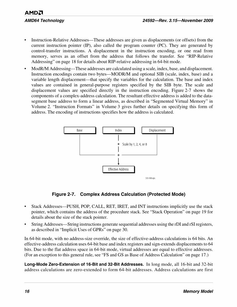
16 Memory Model
AMD64 Technology 24592—Rev. 3.15—November 2009
• Instruction-Relative Addresses—These addresses are given as displacements (or offsets) from thecurrent instruction pointer (IP), also called the program counter (PC). They are generated bycontrol-transfer instructions. A displacement in the instruction encoding, or one read frommemory, serves as an offset from the address that follows the transfer. See “RIP-RelativeAddressing” on page 18 for details about RIP-relative addressing in 64-bit mode.
• ModR/M Addressing—These addresses are calculated using a scale, index, base, and displacement.Instruction encodings contain two bytes—MODR/M and optional SIB (scale, index, base) and avariable length displacement—that specify the variables for the calculation. The base and indexvalues are contained in general-purpose registers specified by the SIB byte. The scale anddisplacement values are specified directly in the instruction encoding. Figure 2-7 shows thecomponents of a complex-address calculation. The resultant effective address is added to the data-segment base address to form a linear address, as described in “Segmented Virtual Memory” inVolume 2. “Instruction Formats” in Volume 3 gives further details on specifying this form ofaddress. The encoding of instructions specifies how the address is calculated.
Figure 2-7. Complex Address Calculation (Protected Mode)
• Stack Addresses—PUSH, POP, CALL, RET, IRET, and INT instructions implicitly use the stackpointer, which contains the address of the procedure stack. See “Stack Operation” on page 19 fordetails about the size of the stack pointer.
• String Addresses—String instructions generate sequential addresses using the rDI and rSI registers,as described in “Implicit Uses of GPRs” on page 30.
In 64-bit mode, with no address-size override, the size of effective-address calculations is 64 bits. Aneffective-address calculation uses 64-bit base and index registers and sign-extends displacements to 64bits. Due to the flat address space in 64-bit mode, virtual addresses are equal to effective addresses.(For an exception to this general rule, see “FS and GS as Base of Address Calculation” on page 17.)
Long-Mode Zero-Extension of 16-Bit and 32-Bit Addresses. In long mode, all 16-bit and 32-bitaddress calculations are zero-extended to form 64-bit addresses. Address calculations are first
+
513-108.eps
*
Effective Address
DisplacementIndex
Scale by 1, 2, 4, or 8
Base
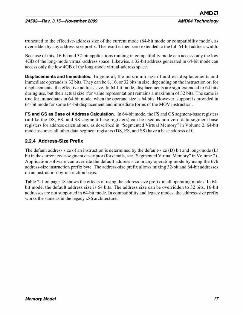
Memory Model 17
24592—Rev. 3.15—November 2009 AMD64 Technology
truncated to the effective-address size of the current mode (64-bit mode or compatibility mode), asoverridden by any address-size prefix. The result is then zero-extended to the full 64-bit address width.
Because of this, 16-bit and 32-bit applications running in compatibility mode can access only the low4GB of the long-mode virtual-address space. Likewise, a 32-bit address generated in 64-bit mode canaccess only the low 4GB of the long-mode virtual-address space.
Displacements and Immediates. In general, the maximum size of address displacements andimmediate operands is 32 bits. They can be 8, 16, or 32 bits in size, depending on the instruction or, fordisplacements, the effective address size. In 64-bit mode, displacements are sign-extended to 64 bitsduring use, but their actual size (for value representation) remains a maximum of 32 bits. The same istrue for immediates in 64-bit mode, when the operand size is 64 bits. However, support is provided in64-bit mode for some 64-bit displacement and immediate forms of the MOV instruction.
FS and GS as Base of Address Calculation. In 64-bit mode, the FS and GS segment-base registers(unlike the DS, ES, and SS segment-base registers) can be used as non-zero data-segment baseregisters for address calculations, as described in “Segmented Virtual Memory” in Volume 2. 64-bitmode assumes all other data-segment registers (DS, ES, and SS) have a base address of 0.
2.2.4 Address-Size Prefix
The default address size of an instruction is determined by the default-size (D) bit and long-mode (L)bit in the current code-segment descriptor (for details, see “Segmented Virtual Memory” in Volume 2).Application software can override the default address size in any operating mode by using the 67haddress-size instruction prefix byte. The address-size prefix allows mixing 32-bit and 64-bit addresseson an instruction-by-instruction basis.
Table 2-1 on page 18 shows the effects of using the address-size prefix in all operating modes. In 64-bit mode, the default address size is 64 bits. The address size can be overridden to 32 bits. 16-bitaddresses are not supported in 64-bit mode. In compatibility and legacy modes, the address-size prefixworks the same as in the legacy x86 architecture.
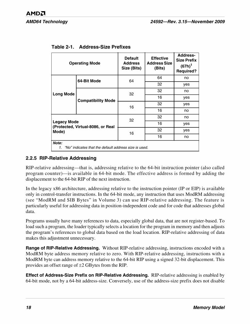
18 Memory Model
AMD64 Technology 24592—Rev. 3.15—November 2009
2.2.5 RIP-Relative Addressing
RIP-relative addressing—that is, addressing relative to the 64-bit instruction pointer (also calledprogram counter)—is available in 64-bit mode. The effective address is formed by adding thedisplacement to the 64-bit RIP of the next instruction.
In the legacy x86 architecture, addressing relative to the instruction pointer (IP or EIP) is availableonly in control-transfer instructions. In the 64-bit mode, any instruction that uses ModRM addressing(see “ModRM and SIB Bytes” in Volume 3) can use RIP-relative addressing. The feature isparticularly useful for addressing data in position-independent code and for code that addresses globaldata.
Programs usually have many references to data, especially global data, that are not register-based. Toload such a program, the loader typically selects a location for the program in memory and then adjuststhe program’s references to global data based on the load location. RIP-relative addressing of datamakes this adjustment unnecessary.
Range of RIP-Relative Addressing. Without RIP-relative addressing, instructions encoded with aModRM byte address memory relative to zero. With RIP-relative addressing, instructions with aModRM byte can address memory relative to the 64-bit RIP using a signed 32-bit displacement. Thisprovides an offset range of ±2 GBytes from the RIP.
Effect of Address-Size Prefix on RIP-Relative Addressing. RIP-relative addressing is enabled by64-bit mode, not by a 64-bit address-size. Conversely, use of the address-size prefix does not disable
Table 2-1. Address-Size Prefixes
Operating ModeDefault
AddressSize (Bits)
EffectiveAddress Size
(Bits)
Address-Size Prefix
(67h)1
Required?
Long Mode
64-Bit Mode 6464 no
32 yes
Compatibility Mode
3232 no
16 yes
1632 yes
16 no
Legacy Mode(Protected, Virtual-8086, or RealMode)
3232 no
16 yes
1632 yes
16 no
Note:1. “No” indicates that the default address size is used.
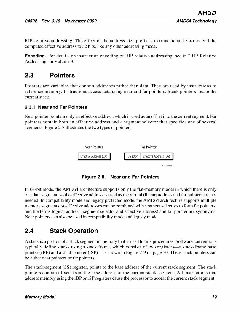
Memory Model 19
24592—Rev. 3.15—November 2009 AMD64 Technology
RIP-relative addressing. The effect of the address-size prefix is to truncate and zero-extend thecomputed effective address to 32 bits, like any other addressing mode.
Encoding. For details on instruction encoding of RIP-relative addressing, see in “RIP-RelativeAddressing” in Volume 3.
2.3 Pointers
Pointers are variables that contain addresses rather than data. They are used by instructions toreference memory. Instructions access data using near and far pointers. Stack pointers locate thecurrent stack.
2.3.1 Near and Far Pointers
Near pointers contain only an effective address, which is used as an offset into the current segment. Farpointers contain both an effective address and a segment selector that specifies one of severalsegments. Figure 2-8 illustrates the two types of pointers.
Figure 2-8. Near and Far Pointers
In 64-bit mode, the AMD64 architecture supports only the flat-memory model in which there is onlyone data segment, so the effective address is used as the virtual (linear) address and far pointers are notneeded. In compatibility mode and legacy protected mode, the AMD64 architecture supports multiplememory segments, so effective addresses can be combined with segment selectors to form far pointers,and the terms logical address (segment selector and effective address) and far pointer are synonyms.Near pointers can also be used in compatibility mode and legacy mode.
2.4 Stack Operation
A stack is a portion of a stack segment in memory that is used to link procedures. Software conventionstypically define stacks using a stack frame, which consists of two registers—a stack-frame basepointer (rBP) and a stack pointer (rSP)—as shown in Figure 2-9 on page 20. These stack pointers canbe either near pointers or far pointers.
The stack-segment (SS) register, points to the base address of the current stack segment. The stackpointers contain offsets from the base address of the current stack segment. All instructions thataddress memory using the rBP or rSP registers cause the processor to access the current stack segment.
513-109.eps
Far PointerNear Pointer
Effective Address (EA) Effective Address (EA)Selector
20 Memory Model
AMD64 Technology 24592—Rev. 3.15—November 2009
Figure 2-9. Stack Pointer Mechanism
In typical APIs, the stack-frame base pointer and the stack pointer point to the same location before aprocedure call (the top-of-stack of the prior stack frame). After data is pushed onto the stack, the stack-frame base pointer remains where it was and the stack pointer advances downward to the addressbelow the pushed data, where it becomes the new top-of-stack.
In legacy and compatibility modes, the default stack pointer size is 16 bits (SP) or 32 bits (ESP),depending on the default-size (B) bit in the stack-segment descriptor, and multiple stacks can bemaintained in separate stack segments. In 64-bit mode, stack pointers are always 64 bits wide (RSP).
Further application-programming details on the stack mechanism are described in “Control Transfers”on page 76. System-programming details on the stack segments are described in “Segmented VirtualMemory” in Volume 2.
2.5 Instruction Pointer
The instruction pointer is used in conjunction with the code-segment (CS) register to locate the nextinstruction in memory. The instruction-pointer register contains the displacement (offset)—from thebase address of the current CS segment, or from address 0 in 64-bit mode—to the next instruction to beexecuted. The pointer is incremented sequentially, except for branch instructions, as described in“Control Transfers” on page 76.
In legacy and compatibility modes, the instruction pointer is a 16-bit (IP) or 32-bit (EIP) register. In64-bit mode, the instruction pointer is extended to a 64-bit (RIP) register to support 64-bit offsets. Thecase-sensitive acronym, rIP, is used to refer to any of these three instruction-pointer sizes, dependingon the software context.
Figure 2-10 on page 21 shows the relationship between RIP, EIP, and IP. The 64-bit RIP can be usedfor RIP-relative addressing, as described in “RIP-Relative Addressing” on page 18.
513-110.eps
Stack-Segment (SS) Base Address
Stack-Frame Base Pointer (rBP)and Stack Pointer (rSP)
Stack-Segment (SS) Base Address
Stack-Frame Base Pointer (rBP)Stack Pointer (rSP)
passed data
Stack Frame Before Procedure Call Stack Frame After Procedure Call
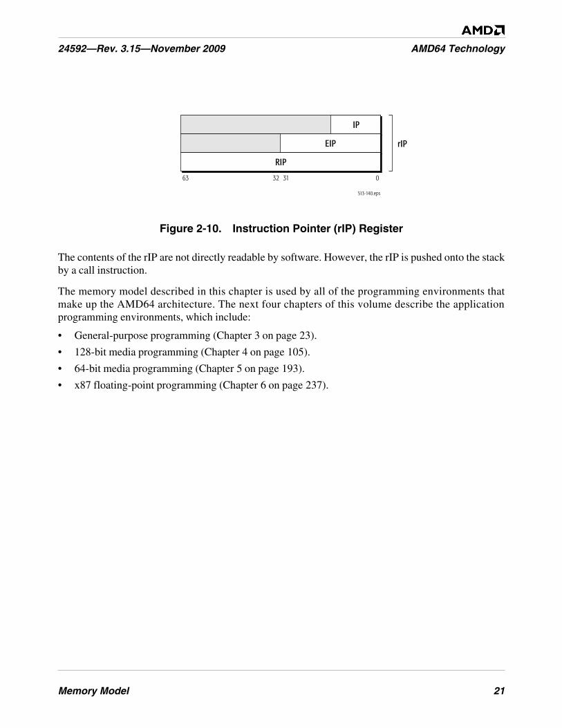
Memory Model 21
24592—Rev. 3.15—November 2009 AMD64 Technology
Figure 2-10. Instruction Pointer (rIP) Register
The contents of the rIP are not directly readable by software. However, the rIP is pushed onto the stackby a call instruction.
The memory model described in this chapter is used by all of the programming environments thatmake up the AMD64 architecture. The next four chapters of this volume describe the applicationprogramming environments, which include:
• General-purpose programming (Chapter 3 on page 23).
• 128-bit media programming (Chapter 4 on page 105).
• 64-bit media programming (Chapter 5 on page 193).
• x87 floating-point programming (Chapter 6 on page 237).
513-140.eps
63 31 032
IP
EIP
RIP
rIP
22 Memory Model
AMD64 Technology 24592—Rev. 3.15—November 2009
General-Purpose Programming 23
24592—Rev. 3.15—November 2009 AMD64 Technology
3 General-Purpose Programming
The general-purpose programming model includes the general-purpose registers (GPRs), integerinstructions and operands that use the GPRs, program-flow control methods, memory optimizationmethods, and I/O. This programming model includes the original x86 integer-programmingarchitecture, plus 64-bit extensions and a few additional instructions. Only the application-programming instructions and resources are described in this chapter. Integer instructions typicallyused in system programming, including all of the privileged instructions, are described in Volume 2,along with other system-programming topics.
The general-purpose programming model is used to some extent by almost all programs, includingprograms consisting primarily of 128-bit media instructions, 64-bit media instructions, x87 floating-point instructions, or system instructions. For this reason, an understanding of the general-purposeprogramming model is essential for any programming work using the AMD64 instruction setarchitecture.
3.1 Registers
Figure 3-1 on page 24 shows an overview of the registers used in general-purpose applicationprogramming. They include the general-purpose registers (GPRs), segment registers, flags register,and instruction-pointer register. The number and width of available registers depends on the operatingmode.
The registers and register ranges shaded light gray in Figure 3-1 on page 24 are available only in 64-bitmode. Those shaded dark gray are available only in legacy mode and compatibility mode. Thus, in 64-bit mode, the 32-bit general-purpose, flags, and instruction-pointer registers available in legacy modeand compatibility mode are extended to 64-bit widths, eight new GPRs are available, and the DS, ES,and SS segment registers are ignored.
When naming registers, if reference is made to multiple register widths, a lower-case r notation isused. For example, the notation rAX refers to the 16-bit AX, 32-bit EAX, or 64-bit RAX register,depending on an instruction’s effective operand size.
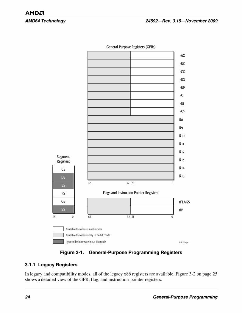
24 General-Purpose Programming
AMD64 Technology 24592—Rev. 3.15—November 2009
Figure 3-1. General-Purpose Programming Registers
3.1.1 Legacy Registers
In legacy and compatibility modes, all of the legacy x86 registers are available. Figure 3-2 on page 25shows a detailed view of the GPR, flag, and instruction-pointer registers.
513-131.eps
63 31 032
R8
R9
R10
R11
R12
R13
R14
R15
rAX
rBX
rCX
rDX
rBP
rSI
rDI
rSP
63 31 032
rFLAGS
rIP
Available to sofware in all modes
Available to sofware only in 64-bit mode
Ignored by hardware in 64-bit mode
15 0
FS
GS
CS
SegmentRegisters
General-Purpose Registers (GPRs)
Flags and Instruction Pointer Registers
ES
SS
DS
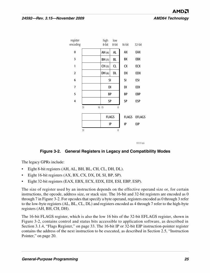
General-Purpose Programming 25
24592—Rev. 3.15—November 2009 AMD64 Technology
Figure 3-2. General Registers in Legacy and Compatibility Modes
The legacy GPRs include:
• Eight 8-bit registers (AH, AL, BH, BL, CH, CL, DH, DL).
• Eight 16-bit registers (AX, BX, CX, DX, DI, SI, BP, SP).
• Eight 32-bit registers (EAX, EBX, ECX, EDX, EDI, ESI, EBP, ESP).
The size of register used by an instruction depends on the effective operand size or, for certaininstructions, the opcode, address size, or stack size. The 16-bit and 32-bit registers are encoded as 0through 7 in Figure 3-2. For opcodes that specify a byte operand, registers encoded as 0 through 3 referto the low-byte registers (AL, BL, CL, DL) and registers encoded as 4 through 7 refer to the high-byteregisters (AH, BH, CH, DH).
The 16-bit FLAGS register, which is also the low 16 bits of the 32-bit EFLAGS register, shown inFigure 3-2, contains control and status bits accessible to application software, as described inSection 3.1.4, “Flags Register,” on page 33. The 16-bit IP or 32-bit EIP instruction-pointer registercontains the address of the next instruction to be executed, as described in Section 2.5, “InstructionPointer,” on page 20.
513-311.eps
31 15 016
EAX
EBX
ECX
EDX
ESI
EDI
EBP
ESP
AX
16-bitlow8-bit
high8-bit 32-bit
BX
CX
DX
SI
DI
BP
SP
AH (4)
BH (7)
CH (5)
DH (6)
AL
BL
CL
DL
SI
DI
BP
SP
FLAGS
IP
31 0
FLAGS
IP
EFLAGS
EIP
0
3
1
2
6
7
5
4
registerencoding
26 General-Purpose Programming
AMD64 Technology 24592—Rev. 3.15—November 2009
3.1.2 64-Bit-Mode Registers
In 64-bit mode, eight new GPRs are added to the eight legacy GPRs, all 16 GPRs are 64 bits wide, andthe low bytes of all registers are accessible. Figure 3-3 on page 27 shows the GPRs, flags register, andinstruction-pointer register available in 64-bit mode. The GPRs include:
• Sixteen 8-bit low-byte registers (AL, BL, CL, DL, SIL, DIL, BPL, SPL, R8B, R9B, R10B, R11B,R12B, R13B, R14B, R15B).
• Four 8-bit high-byte registers (AH, BH, CH, DH), addressable only when no REX prefix is used.
• Sixteen 16-bit registers (AX, BX, CX, DX, DI, SI, BP, SP, R8W, R9W, R10W, R11W, R12W,R13W, R14W, R15W).
• Sixteen 32-bit registers (EAX, EBX, ECX, EDX, EDI, ESI, EBP, ESP, R8D, R9D, R10D, R11D,R12D, R13D, R14D, R15D).
• Sixteen 64-bit registers (RAX, RBX, RCX, RDX, RDI, RSI, RBP, RSP, R8, R9, R10, R11, R12,R13, R14, R15).
The size of register used by an instruction depends on the effective operand size or, for certaininstructions, the opcode, address size, or stack size. For most instructions, access to the extended GPRsrequires a REX prefix (Section 3.5.2, “REX Prefixes,” on page 74). The four high-byte registers (AH,BH, CH, DH) available in legacy mode are not addressable when a REX prefix is used.
In general, byte and word operands are stored in the low 8 or 16 bits of GPRs without modifying theirhigh 56 or 48 bits, respectively. Doubleword operands, however, are normally stored in the low 32 bitsof GPRs and zero-extended to 64 bits.
The 64-bit RFLAGS register, shown in Figure 3-3 on page 27, contains the legacy EFLAGS in its low32-bit range. The high 32 bits are reserved. They can be written with anything but they always read aszero (RAZ). The 64-bit RIP instruction-pointer register contains the address of the next instruction tobe executed, as described in Section 3.1.5, “Instruction Pointer Register,” on page 36.
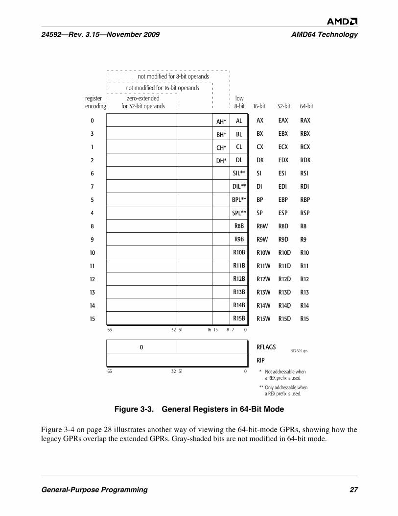
General-Purpose Programming 27
24592—Rev. 3.15—November 2009 AMD64 Technology
Figure 3-3. General Registers in 64-Bit Mode
Figure 3-4 on page 28 illustrates another way of viewing the 64-bit-mode GPRs, showing how thelegacy GPRs overlap the extended GPRs. Gray-shaded bits are not modified in 64-bit mode.
513-309.eps
63 31 15 7 081632
R8
R9
R10
R11
R12
R13
R14
R15
R8W
R9W
R10W
R11W
R12W
R13W
R14W
R15W
R8D
R9D
R10D
R11D
R12D
R13D
R14D
R15D
EAX
EBX
ECX
EDX
ESI
EDI
EBP
ESP
RAX
RBX
RCX
RDX
RSI
RDI
RBP
RSP
AXAH*
BH*
CH*
DH*
16-bit 32-bit 64-bit
8
9
10
11
12
13
14
15
0
3
1
2
6
7
5
4
registerencoding
zero-extendedfor 32-bit operands
not modified for 8-bit operands
not modified for 16-bit operands
BX
CX
DX
SI
DI
BP
SP
63 31 032
RFLAGS
RIP
0
low8-bit
R8B
R9B
R10B
R11B
R12B
R13B
R14B
R15B
AL
BL
CL
DL
SIL**
DIL**
BPL**
SPL**
* Not addressable whena REX prefix is used.
** Only addressable whena REX prefix is used.
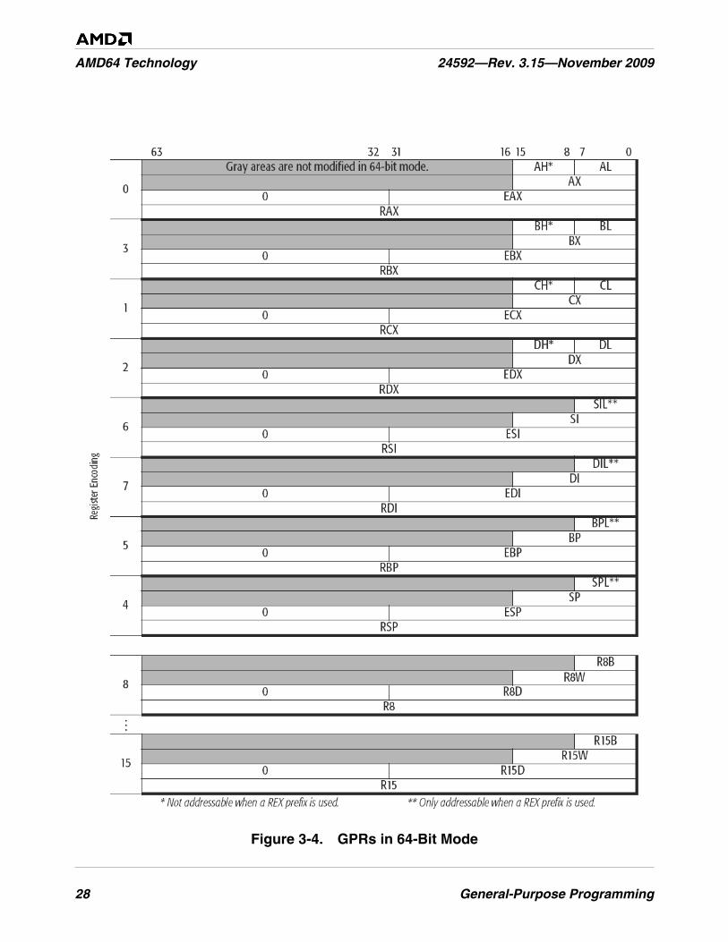
28 General-Purpose Programming
AMD64 Technology 24592—Rev. 3.15—November 2009
Figure 3-4. GPRs in 64-Bit Mode
General-Purpose Programming 29
24592—Rev. 3.15—November 2009 AMD64 Technology
Default Operand Size. For most instructions, the default operand size in 64-bit mode is 32 bits. Toaccess 16-bit operand sizes, an instruction must contain an operand-size prefix (66h), as described inSection 3.2.2, “Operand Sizes and Overrides,” on page 39. To access the full 64-bit operand size, mostinstructions must contain a REX prefix.
For details on operand size, see Section 3.2.2, “Operand Sizes and Overrides,” on page 39.
Byte Registers. 64-bit mode provides a uniform set of low-byte, low-word, low-doubleword, andquadword registers that is well-suited for register allocation by compilers. Access to the four new low-byte registers in the legacy-GPR range (SIL, DIL, BPL, SPL), or any of the low-byte registers in theextended registers (R8B–R15B), requires a REX instruction prefix. However, the legacy high-byteregisters (AH, BH, CH, DH) are not accessible when a REX prefix is used.
Zero-Extension of 32-Bit Results. As Figure 3-3 on page 27 and Figure 3-4 on page 28 show, whenperforming 32-bit operations with a GPR destination in 64-bit mode, the processor zero-extends the32-bit result into the full 64-bit destination. 8-bit and 16-bit operations on GPRs preserve all unwrittenupper bits of the destination GPR. This is consistent with legacy 16-bit and 32-bit semantics forpartial-width results.
Software should explicitly sign-extend the results of 8-bit, 16-bit, and 32-bit operations to the full 64-bit width before using the results in 64-bit address calculations.
The following four code examples show how 64-bit, 32-bit, 16-bit, and 8-bit ADDs work. In theseexamples, “48” is a REX prefix specifying 64-bit operand size, and “01C3” and “00C3” are the opcodeand ModRM bytes of each instruction (see “Opcode Syntax” in Volume 3 for details on the opcode andModRM encoding).
Example 1: 64-bit Add:
Before:RAX =0002_0001_8000_2201RBX =0002_0002_0123_3301
48 01C3 ADD RBX,RAX ;48 is a REX prefix for size.
Result:RBX = 0004_0003_8123_5502
Example 2: 32-bit Add:
Before:RAX = 0002_0001_8000_2201RBX = 0002_0002_0123_3301
01C3 ADD EBX,EAX ;32-bit add
Result:RBX = 0000_0000_8123_5502(32-bit result is zero extended)
Example 3: 16-bit Add:
Before:RAX = 0002_0001_8000_2201RBX = 0002_0002_0123_3301
30 General-Purpose Programming
AMD64 Technology 24592—Rev. 3.15—November 2009
66 01C3 ADD BX,AX ;66 is 16-bit size override
Result:RBX = 0002_0002_0123_5502(bits 63:16 are preserved)
Example 4: 8-bit Add:
Before:RAX = 0002_0001_8000_2201RBX = 0002_0002_0123_3301
00C3 ADD BL,AL ;8-bit add
Result:RBX = 0002_0002_0123_3302(bits 63:08 are preserved)
GPR High 32 Bits Across Mode Switches. The processor does not preserve the upper 32 bits of the64-bit GPRs across switches from 64-bit mode to compatibility or legacy modes. When using 32-bitoperands in compatibility or legacy mode, the high 32 bits of GPRs are undefined. Software must notrely on these undefined bits, because they can change from one implementation to the next or even ona cycle-to-cycle basis within a given implementation. The undefined bits are not a function of the dataleft by any previously running process.
3.1.3 Implicit Uses of GPRs
Most instructions can use any of the GPRs for operands. However, as Figure 3-1 on page 31 shows,some instructions use some GPRs implicitly. Details about implicit use of GPRs are described in“General-Purpose Instruction Reference” in Volume 3.
Table 3-1 on page 31 shows implicit register uses only for application instructions. Certain systeminstructions also make implicit use of registers. These system instructions are described in “SystemInstruction Reference” in Volume 3.
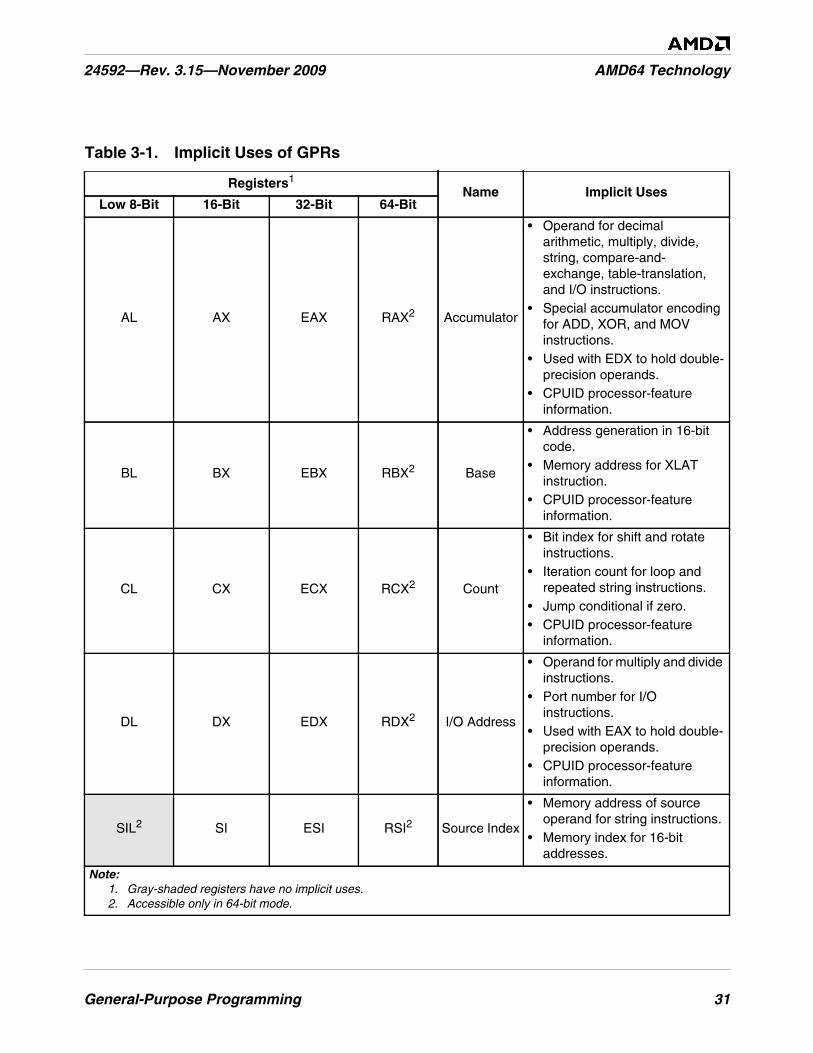
General-Purpose Programming 31
24592—Rev. 3.15—November 2009 AMD64 Technology
Table 3-1. Implicit Uses of GPRs
Registers1Name Implicit Uses
Low 8-Bit 16-Bit 32-Bit 64-Bit
AL AX EAX RAX2 Accumulator
• Operand for decimalarithmetic, multiply, divide,string, compare-and-exchange, table-translation,and I/O instructions.
• Special accumulator encodingfor ADD, XOR, and MOVinstructions.
• Used with EDX to hold double-precision operands.
• CPUID processor-featureinformation.
BL BX EBX RBX2 Base
• Address generation in 16-bitcode.
• Memory address for XLATinstruction.
• CPUID processor-featureinformation.
CL CX ECX RCX2 Count
• Bit index for shift and rotateinstructions.
• Iteration count for loop andrepeated string instructions.
• Jump conditional if zero.• CPUID processor-feature
information.
DL DX EDX RDX2 I/O Address
• Operand for multiply and divideinstructions.
• Port number for I/Oinstructions.
• Used with EAX to hold double-precision operands.
• CPUID processor-featureinformation.
SIL2 SI ESI RSI2 Source Index
• Memory address of sourceoperand for string instructions.
• Memory index for 16-bitaddresses.
Note:1. Gray-shaded registers have no implicit uses.2. Accessible only in 64-bit mode.
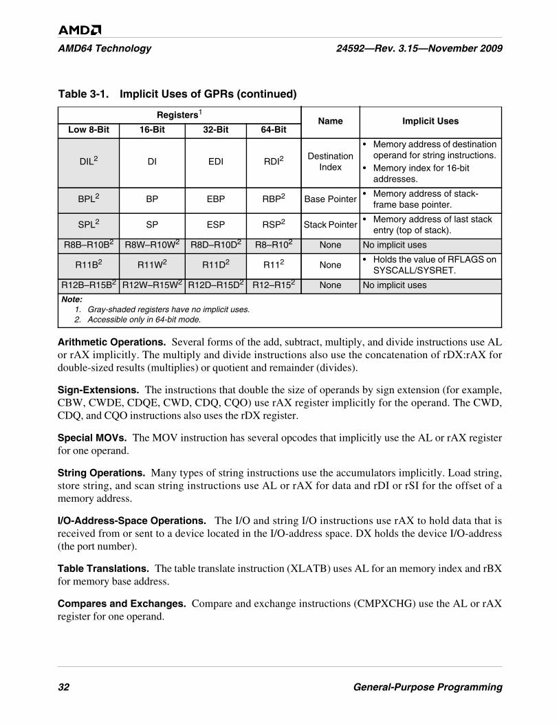
32 General-Purpose Programming
AMD64 Technology 24592—Rev. 3.15—November 2009
Arithmetic Operations. Several forms of the add, subtract, multiply, and divide instructions use ALor rAX implicitly. The multiply and divide instructions also use the concatenation of rDX:rAX fordouble-sized results (multiplies) or quotient and remainder (divides).
Sign-Extensions. The instructions that double the size of operands by sign extension (for example,CBW, CWDE, CDQE, CWD, CDQ, CQO) use rAX register implicitly for the operand. The CWD,CDQ, and CQO instructions also uses the rDX register.
Special MOVs. The MOV instruction has several opcodes that implicitly use the AL or rAX registerfor one operand.
String Operations. Many types of string instructions use the accumulators implicitly. Load string,store string, and scan string instructions use AL or rAX for data and rDI or rSI for the offset of amemory address.
I/O-Address-Space Operations. The I/O and string I/O instructions use rAX to hold data that isreceived from or sent to a device located in the I/O-address space. DX holds the device I/O-address(the port number).
Table Translations. The table translate instruction (XLATB) uses AL for an memory index and rBXfor memory base address.
Compares and Exchanges. Compare and exchange instructions (CMPXCHG) use the AL or rAXregister for one operand.
DIL2 DI EDI RDI2Destination
Index
• Memory address of destinationoperand for string instructions.
• Memory index for 16-bitaddresses.
BPL2 BP EBP RBP2 Base Pointer• Memory address of stack-
frame base pointer.
SPL2 SP ESP RSP2 Stack Pointer• Memory address of last stack
entry (top of stack).
R8B–R10B2 R8W–R10W2 R8D–R10D2 R8–R102 None No implicit uses
R11B2 R11W2 R11D2 R112 None• Holds the value of RFLAGS on
SYSCALL/SYSRET.
R12B–R15B2 R12W–R15W2 R12D–R15D2 R12–R152 None No implicit uses
Table 3-1. Implicit Uses of GPRs (continued)
Registers1Name Implicit Uses
Low 8-Bit 16-Bit 32-Bit 64-Bit
Note:1. Gray-shaded registers have no implicit uses.2. Accessible only in 64-bit mode.
General-Purpose Programming 33
24592—Rev. 3.15—November 2009 AMD64 Technology
Decimal Arithmetic. The decimal arithmetic instructions (AAA, AAD, AAM, AAS, DAA, DAS)that adjust binary-coded decimal (BCD) operands implicitly use the AL and AH register for theiroperations.
Shifts and Rotates. Shift and rotate instructions can use the CL register to specify the number of bitsan operand is to be shifted or rotated.
Conditional Jumps. Special conditional-jump instructions use the rCX register instead of flags. TheJCXZ and JrCXZ instructions check the value of the rCX register and pass control to the targetinstruction when the value of rCX register reaches 0.
Repeated String Operations. With the exception of I/O string instructions, all string operations userSI as the source-operand pointer and rDI as the destination-operand pointer. I/O string instructionsuse rDX to specify the input-port or output-port number. For repeated string operations (thosepreceded with a repeat-instruction prefix), the rSI and rDI registers are incremented or decremented asthe string elements are moved from the source location to the destination. Repeat-string operationsalso use rCX to hold the string length, and decrement it as data is moved from one location to the other.
Stack Operations. Stack operations make implicit use of the rSP register, and in some cases, the rBPregister. The rSP register is used to hold the top-of-stack pointer (or simply, stack pointer). rSP isdecremented when items are pushed onto the stack, and incremented when they are popped off thestack. The ENTER and LEAVE instructions use rBP as a stack-frame base pointer. Here, rBP points tothe last entry in a data structure that is passed from one block-structured procedure to another.
The use of rSP or rBP as a base register in an address calculation implies the use of SS (stack segment)as the default segment. Using any other GPR as a base register without a segment-override prefiximplies the use of the DS data segment as the default segment.
The push all and pop all instructions (PUSHA, PUSHAD, POPA, POPAD) implicitly use all of theGPRs.
CPUID Information. The CPUID instruction makes implicit use of the EAX, EBX, ECX, and EDXregisters. Software loads a function code into EAX, executes the CPUID instruction, and then reads theassociated processor-feature information in EAX, EBX, ECX, and EDX.
3.1.4 Flags Register
Figure 3-5 on page 34 shows the 64-bit RFLAGS register and the flag bits visible to applicationsoftware. Bits 15–0 are the FLAGS register (accessed in legacy real and virtual-8086 modes), bits31–0 are the EFLAGS register (accessed in legacy protected mode and compatibility mode), and bits63–0 are the RFLAGS register (accessed in 64-bit mode). The name rFLAGS refers to any of the threeregister widths, depending on the current software context.
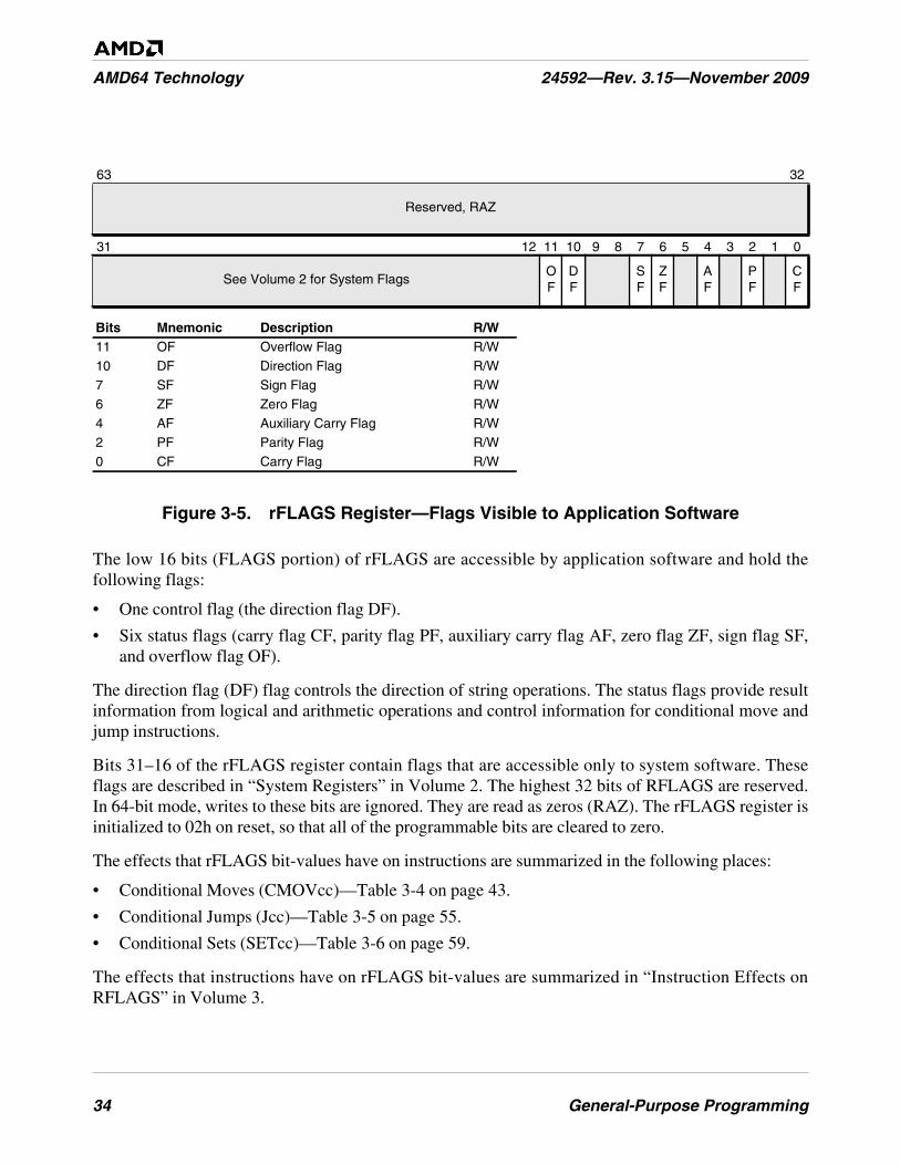
34 General-Purpose Programming
AMD64 Technology 24592—Rev. 3.15—November 2009
Figure 3-5. rFLAGS Register—Flags Visible to Application Software
The low 16 bits (FLAGS portion) of rFLAGS are accessible by application software and hold thefollowing flags:
• One control flag (the direction flag DF).
• Six status flags (carry flag CF, parity flag PF, auxiliary carry flag AF, zero flag ZF, sign flag SF,and overflow flag OF).
The direction flag (DF) flag controls the direction of string operations. The status flags provide resultinformation from logical and arithmetic operations and control information for conditional move andjump instructions.
Bits 31–16 of the rFLAGS register contain flags that are accessible only to system software. Theseflags are described in “System Registers” in Volume 2. The highest 32 bits of RFLAGS are reserved.In 64-bit mode, writes to these bits are ignored. They are read as zeros (RAZ). The rFLAGS register isinitialized to 02h on reset, so that all of the programmable bits are cleared to zero.
The effects that rFLAGS bit-values have on instructions are summarized in the following places:
• Conditional Moves (CMOVcc)—Table 3-4 on page 43.
• Conditional Jumps (Jcc)—Table 3-5 on page 55.
• Conditional Sets (SETcc)—Table 3-6 on page 59.
The effects that instructions have on rFLAGS bit-values are summarized in “Instruction Effects onRFLAGS” in Volume 3.
63 32
Reserved, RAZ
31 12 11 10 9 8 7 6 5 4 3 2 1 0
See Volume 2 for System FlagsOF
DF
SF
ZF
AF
PF
CF
Bits Mnemonic Description R/W11 OF Overflow Flag R/W10 DF Direction Flag R/W7 SF Sign Flag R/W6 ZF Zero Flag R/W4 AF Auxiliary Carry Flag R/W2 PF Parity Flag R/W0 CF Carry Flag R/W
General-Purpose Programming 35
24592—Rev. 3.15—November 2009 AMD64 Technology
The sections below describe each application-visible flag. All of these flags are readable and writable.For example, the POPF, POPFD, POPFQ, IRET, IRETD, and IRETQ instructions write all flags. Thecarry and direction flags are writable by dedicated application instructions. Other application-visibleflags are written indirectly by specific instructions. Reserved bits and bits whose writability isprevented by the current values of system flags, current privilege level (CPL), or the current operatingmode, are unaffected by the POPFx instructions.
Carry Flag (CF). Bit 0. Hardware sets the carry flag to 1 if the last integer addition or subtractionoperation resulted in a carry (for addition) or a borrow (for subtraction) out of the most-significant bitposition of the result. Otherwise, hardware clears the flag to 0.
The increment and decrement instructions—unlike the addition and subtraction instructions—do notaffect the carry flag. The bit shift and bit rotate instructions shift bits of operands into the carry flag.Logical instructions like AND, OR, XOR clear the carry flag. Bit-test instructions (BTx) set the valueof the carry flag depending on the value of the tested bit of the operand.
Software can set or clear the carry flag with the STC and CLC instructions, respectively. Software cancomplement the flag with the CMC instruction.
Parity Flag (PF). Bit 2. Hardware sets the parity flag to 1 if there is an even number of 1 bits in theleast-significant byte of the last result of certain operations. Otherwise (i.e., for an odd number of 1bits), hardware clears the flag to 0. Software can read the flag to implement parity checking.
Auxiliary Carry Flag (AF). Bit 4. Hardware sets the auxiliary carry flag if an arithmetic operation ora binary-coded decimal (BCD) operation generates a carry (in the case of an addition) or a borrow (inthe case of a subtraction) out of bit 3 of the result. Otherwise, AF is cleared to zero.
The main application of this flag is to support decimal arithmetic operations. Most commonly, this flagis used internally by correction commands for decimal addition (AAA) and subtraction (AAS).
Zero Flag (ZF). Bit 6. Hardware sets the zero flag to 1 if the last arithmetic operation resulted in avalue of zero. Otherwise (for a non-zero result), hardware clears the flag to 0. The compare and testinstructions also affect the zero flag.
The zero flag is typically used to test whether the result of an arithmetic or logical operation is zero, orto test whether two operands are equal.
Sign Flag (SF). Bit 7. Hardware sets the sign flag to 1 if the last arithmetic operation resulted in anegative value. Otherwise (for a positive-valued result), hardware clears the flag to 0. Thus, in suchoperations, the value of the sign flag is set equal to the value of the most-significant bit of the result.Depending on the size of operands, the most-significant bit is bit 7 (for bytes), bit 15 (for words), bit 31(for doublewords), or bit 63 (for quadwords).
Direction Flag (DF). Bit 10. The direction flag determines the order in which strings are processed.Software can set the direction flag to 1 to specify decrementing the data pointer for the next stringinstruction (LODSx, STOSx, MOVSx, SCASx, CMPSx, OUTSx, or INSx). Clearing the direction flag
36 General-Purpose Programming
AMD64 Technology 24592—Rev. 3.15—November 2009
to 0 specifies incrementing the data pointer. The pointers are stored in the rSI or rDI register. Softwarecan set or clear the flag with the STD and CLD instructions, respectively.
Overflow Flag (OF). Bit 11. Hardware sets the overflow flag to 1 to indicate that the most-significant(sign) bit of the result of the last signed integer operation differed from the signs of both sourceoperands. Otherwise, hardware clears the flag to 0. A set overflow flag means that the magnitude of thepositive or negative result is too big (overflow) or too small (underflow) to fit its defined data type.
The OF flag is undefined after the DIV instruction and after a shift of more than one bit. Logicalinstructions clear the overflow flag.
3.1.5 Instruction Pointer Register
The instruction pointer register—IP, EIP, or RIP, or simply rIP for any of the three depending on thecontext—is used in conjunction with the code-segment (CS) register to locate the next instruction inmemory. See Section 2.5, “Instruction Pointer,” on page 20 for details.
3.2 Operands
Operands are either referenced by an instruction's encoding or included as an immediate value in theinstruction encoding. Depending on the instruction, referenced operands can be located in registers,memory locations, or I/O ports.
3.2.1 Data Types
Figure 3-6 on page 37 shows the register images of the general-purpose data types. In the general-purpose programming environment, these data types can be interpreted by instruction syntax or thesoftware context as the following types of numbers and strings:
• Signed (two's-complement) integers.
• Unsigned integers.
• BCD digits.
• Packed BCD digits.
• Strings, including bit strings.
The double quadword data type is supported in the RDX:RAX registers by the MUL, IMUL, DIV,IDIV, and CQO instructions. Software can interpret the data types in ways other than those shown inFigure 3-6 on page 37 but the AMD64 instruction set does not directly support such interpretationsand software must handle them entirely on its own.
Table 3-2 on page 37 shows the range of representable values for the general-purpose data types.
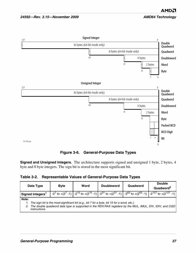
General-Purpose Programming 37
24592—Rev. 3.15—November 2009 AMD64 Technology
Figure 3-6. General-Purpose Data Types
Signed and Unsigned Integers. The architecture supports signed and unsigned 1 byte, 2 bytes, 4byte and 8 byte integers. The sign bit is stored in the most significant bit.
Table 3-2. Representable Values of General-Purpose Data Types
Data Type Byte Word Doubleword QuadwordDouble
Quadword2
Signed Integers1 -27 to +(27 -1) -215 to +(215 -1) -231 to +(231 -1) -263 to +(263 -1) -2127 to +(2127 -1)
Note:1. The sign bit is the most-significant bit (e.g., bit 7 for a byte, bit 15 for a word, etc.).2. The double quadword data type is supported in the RDX:RAX registers by the MUL, IMUL, DIV, IDIV, and CQO
instructions.
513-326.eps
127
63
63
31
15
7 0
Quadword
DoubleQuadword
Doubleword
Word
Byte
0
s
s
s
s
Quadword
Unsigned Integer
Signed Integer
Doubleword
Word
Byte
Bit
8 bytes (64-bit mode only)
s 16 bytes (64-bit mode only)
127DoubleQuadword
0
16 bytes (64-bit mode only)
4 bytes
2 bytes
31
15
7 3
Packed BCD
BCD Digit
0
8 bytes (64-bit mode only)
4 bytes
2 bytes
38 General-Purpose Programming
AMD64 Technology 24592—Rev. 3.15—November 2009
Binary-Coded-Decimal (BCD) Digits. BCD digits have values ranging from 0 to 9. These values canbe represented in binary encoding with four bits. For example, 0000b represents the decimal number 0and 1001b represents the decimal number 9. Values ranging from 1010b to 1111b are invalid for thisdata type. Because a byte contains eight bits, two BCD digits can be stored in a single byte. This isreferred to as packed-BCD. If a single BCD digit is stored per byte, it is referred to as unpacked-BCD.In the x87 floating-point programming environment (described in Section 6, “x87 Floating-PointProgramming,” on page 237) an 80-bit packed BCD data type is also supported, along withconversions between floating-point and BCD data types, so that data expressed in the BCD format canbe operated on as floating-point values.
Integer add, subtract, multiply, and divide instructions can be used to operate on single (unpacked)BCD digits. The result must be adjusted to produce a correct BCD representation. For unpacked BCDnumbers, the ASCII-adjust instructions are provided to simplify that correction. In the case of division,the adjustment must be made prior to executing the integer-divide instruction.
Similarly, integer add and subtract instructions can be used to operate on packed-BCD digits. Theresult must be adjusted to produce a correct packed-BCD representation. Decimal-adjust instructionsare provided to simplify packed-BCD result corrections.
Strings. Strings are a continuous sequence of a single data type. The string instructions can be used tooperate on byte, word, doubleword, or quadword data types. The maximum length of a string of anydata type is 232–1 bytes, in legacy or compatibility modes, or 264–1 bytes in 64-bit mode. One of themore common types of strings used by applications are byte data-type strings known as ASCII strings,which can be used to represent character data.
Bit strings are also supported by instructions that operate specifically on bit strings. In general, bitstrings can start and end at any bit location within any byte, although the BTx bit-string instructionsassume that strings start on a byte boundary. The length of a bit string can range in size from a singlebit up to 232–1 bits, in legacy or compatibility modes, or 264-–1 bits in 64-bit mode.
Unsigned Integers0 to +28-1(0 to 255)
0 to +216-1(0 to 65,535)
0 to +232-1(0 to 4.29 x 10⁹)
0 to +264-1(0 to 1.84 x 10¹⁹)
0 to +2128-1(0 to 3.40 x 1038)
Packed BCDDigits
00 to 99 multiple packed BCD-digit bytes
BCD Digit 0 to 9 multiple BCD-digit bytes
Table 3-2. Representable Values of General-Purpose Data Types (continued)
Data Type Byte Word Doubleword QuadwordDouble
Quadword2
Note:1. The sign bit is the most-significant bit (e.g., bit 7 for a byte, bit 15 for a word, etc.).2. The double quadword data type is supported in the RDX:RAX registers by the MUL, IMUL, DIV, IDIV, and CQO
instructions.
General-Purpose Programming 39
24592—Rev. 3.15—November 2009 AMD64 Technology
3.2.2 Operand Sizes and Overrides
Default Operand Size. In legacy and compatibility modes, the default operand size is either 16 bitsor 32 bits, as determined by the default-size (D) bit in the current code-segment descriptor (for details,see “Segmented Virtual Memory” in Volume 2). In 64-bit mode, the default operand size for mostinstructions is 32 bits.
Application software can override the default operand size by using an operand-size instruction prefix.Table 3-3 shows the instruction prefixes for operand-size overrides in all operating modes. In 64-bitmode, the default operand size for most instructions is 32 bits. A REX prefix (see Section 3.5.2, “REXPrefixes,” on page 74) specifies a 64-bit operand size, and a 66h prefix specifies a 16-bit operand size.The REX prefix takes precedence over the 66h prefix.
There are several exceptions to the 32-bit operand-size default in 64-bit mode, including near branchesand instructions that implicitly reference the RSP stack pointer. For example, the near CALL, nearJMP, Jcc, LOOPcc, POP, and PUSH instructions all default to a 64-bit operand size in 64-bit mode.Such instructions do not need a REX prefix for the 64-bit operand size. For details, see “General-Purpose Instructions in 64-Bit Mode” in Volume 3.
Effective Operand Size. The term effective operand size describes the operand size for the currentinstruction, after accounting for the instruction’s default operand size and any operand-size override orREX prefix that is used with the instruction.
Table 3-3. Operand-Size Overrides
Operating ModeDefault
OperandSize (Bits)
EffectiveOperand
Size(Bits)
Instruction Prefix
66h1 REX
LongMode
64-BitMode
322
64 x yes
32 no no
16 yes no
CompatibilityMode
3232 no
NotApplicable
16 yes
1632 yes
16 no
Legacy Mode(Protected, Virtual-8086,or Real Mode)
3232 no
16 yes
1632 yes
16 no
Note:1. A “no” indicates that the default operand size is used. An “x” means “don’t care.”2. Near branches, instructions that implicitly reference the stack pointer, and certain
other instructions default to 64-bit operand size. See “General-Purpose Instructionsin 64-Bit Mode” in Volume 3
40 General-Purpose Programming
AMD64 Technology 24592—Rev. 3.15—November 2009
Immediate Operand Size. In legacy mode and compatibility modes, the size of immediate operandscan be 8, 16, or 32 bits, depending on the instruction. In 64-bit mode, the maximum size of animmediate operand is also 32 bits, except that 64-bit immediates can be copied into a 64-bit GPR usingthe MOV instruction.
When the operand size of a MOV instruction is 64 bits, the processor sign-extends immediates to 64bits before using them. Support for true 64-bit immediates is accomplished by expanding thesemantics of the MOV reg, imm16/32 instructions. In legacy and compatibility modes, theseinstructions—opcodes B8h through BFh—copy a 16-bit or 32-bit immediate (depending on theeffective operand size) into a GPR. In 64-bit mode, if the operand size is 64 bits (requires a REXprefix), these instructions can be used to copy a true 64-bit immediate into a GPR.
3.2.3 Operand Addressing
Operands for general-purpose instructions are referenced by the instruction's syntax or they areincorporated in the instruction as an immediate value. Referenced operands can be in registers,memory, or I/O ports.
Register Operands. Most general-purpose instructions that take register operands reference thegeneral-purpose registers (GPRs). A few general-purpose instructions reference operands in theRFLAGS register, XMM registers, or MMX™ registers.
The type of register addressed is specified in the instruction syntax. When addressing GPRs or XMMregisters, the REX instruction prefix can be used to access the extended GPRs or XMM registers, asdescribed in Section 3.5, “Instruction Prefixes,” on page 71.
Memory Operands. Many general-purpose instructions can access operands in memory. Section 2.2,“Memory Addressing,” on page 14 describes the general methods and conditions for addressingmemory operands.
I/O Ports. Operands in I/O ports are referenced according to the conventions described in Section 3.8,“Input/Output,” on page 90.
Immediate Operands. In certain instructions, a source operand—called an immediate operand, orsimply immediate—is included as part of the instruction rather than being accessed from a register ormemory location. For details on the size of immediate operands, see “Immediate Operand Size” onpage 40.
3.2.4 Data Alignment
A data access is aligned if its address is a multiple of its operand size, in bytes. The following examplesillustrate this definition:
• Byte accesses are always aligned. Bytes are the smallest addressable parts of memory.
• Word (two-byte) accesses are aligned if their address is a multiple of 2.
• Doubleword (four-byte) accesses are aligned if their address is a multiple of 4.
• Quadword (eight-byte) accesses are aligned if their address is a multiple of 8.

General-Purpose Programming 41
24592—Rev. 3.15—November 2009 AMD64 Technology
The AMD64 architecture does not impose data-alignment requirements for accessing data in memory.However, depending on the location of the misaligned operand with respect to the width of the data busand other aspects of the hardware implementation (such as store-to-load forwarding mechanisms), amisaligned memory access can require more bus cycles than an aligned access. For maximumperformance, avoid misaligned memory accesses.
Performance on many hardware implementations will benefit from observing the following operand-alignment and operand-size conventions:
• Avoid misaligned data accesses.
• Maintain consistent use of operand size across all loads and stores. Larger operand sizes(doubleword and quadword) tend to make more efficient use of the data bus and any data-forwarding features that are implemented by the hardware.
• When using word or byte stores, avoid loading data from the same doubleword of memory, otherthan the identical start addresses of the stores.
3.3 Instruction Summary
This section summarizes the functions of the general-purpose instructions. The instructions areorganized by functional group—such as, data-transfer instructions, arithmetic instructions, and so on.Details on individual instructions are given in the alphabetically organized “General-PurposeInstruction Reference” in Volume 3.
3.3.1 Syntax
Each instruction has a mnemonic syntax used by assemblers to specify the operation and the operandsto be used for source and destination (result) data. Figure 3-7 shows an example of the mnemonicsyntax for a compare (CMP) instruction. In this example, the CMP mnemonic is followed by twooperands, a 32-bit register or memory operand and an 8-bit immediate operand.
Figure 3-7. Mnemonic Syntax Example
513-139.eps
Mnemonic
First Source Operandand Destination Operand
Second Source Operand
CMP reg/mem32, imm8
42 General-Purpose Programming
AMD64 Technology 24592—Rev. 3.15—November 2009
In most instructions that take two operands, the first (left-most) operand is both a source operand andthe destination operand. The second (right-most) operand serves only as a source. Instructions canhave one or more prefixes that modify default instruction functions or operand properties. Theseprefixes are summarized in Section 3.5, “Instruction Prefixes,” on page 71. Instructions that access64-bit operands in a general-purpose register (GPR) or any of the extended GPR or XMM registersrequire a REX instruction prefix.
Unless otherwise stated in this section, the word register means a general-purpose register (GPR).Several instructions affect the flag bits in the RFLAGS register. “Instruction Effects on RFLAGS” inVolume 3 summarizes the effects that instructions have on rFLAGS bits.
3.3.2 Data Transfer
The data-transfer instructions copy data between registers and memory.
Move
• MOV—Move
• MOVSX—Move with Sign-Extend
• MOVZX—Move with Zero-Extend
• MOVD—Move Doubleword or Quadword
• MOVNTI—Move Non-Temporal Doubleword or Quadword
MOVx copies a byte, word, doubleword, or quadword from a register or memory location to a registeror memory location. The source and destination cannot both be memory locations. An immediateconstant can be used as a source operand with the MOV instruction. For MOV, the destination must beof the same size as the source, but the MOVSX and MOVZX instructions copy values of smaller size toa larger size by using sign-extension or zero-extension. The MOVD instruction copies a doubleword orquadword between a general-purpose register or memory and an XMM or MMX register.
The MOV instruction is in many aspects similar to the assignment operator in high-level languages.The simplest example of their use is to initialize variables. To initialize a register to 0, rather than usinga MOV instruction it may be more efficient to use the XOR instruction with identical destination andsource operands.
The MOVNTI instruction stores a doubleword or quadword from a register into memory as “non-temporal” data, which assumes a single access (as opposed to frequent subsequent accesses of“temporal data”). The operation therefore minimizes cache pollution. The exact method by whichcache pollution is minimized depends on the hardware implementation of the instruction. For furtherinformation, see Section 3.9, “Memory Optimization,” on page 92.
Conditional Move
• CMOVcc—Conditional Move If condition
The CMOVcc instructions conditionally copy a word, doubleword, or quadword from a register ormemory location to a register location. The source and destination must be of the same size.
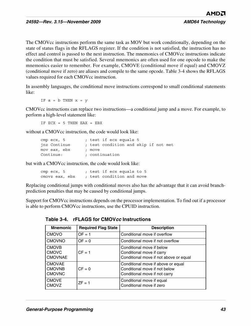
General-Purpose Programming 43
24592—Rev. 3.15—November 2009 AMD64 Technology
The CMOVcc instructions perform the same task as MOV but work conditionally, depending on thestate of status flags in the RFLAGS register. If the condition is not satisfied, the instruction has noeffect and control is passed to the next instruction. The mnemonics of CMOVcc instructions indicatethe condition that must be satisfied. Several mnemonics are often used for one opcode to make themnemonics easier to remember. For example, CMOVE (conditional move if equal) and CMOVZ(conditional move if zero) are aliases and compile to the same opcode. Table 3-4 shows the RFLAGSvalues required for each CMOVcc instruction.
In assembly languages, the conditional move instructions correspond to small conditional statementslike:
IF a = b THEN x = y
CMOVcc instructions can replace two instructions—a conditional jump and a move. For example, toperform a high-level statement like:
IF ECX = 5 THEN EAX = EBX
without a CMOVcc instruction, the code would look like:
cmp ecx, 5 ; test if ecx equals 5jnz Continue ; test condition and skip if not metmov eax, ebx ; moveContinue: ; continuation
but with a CMOVcc instruction, the code would look like:
cmp ecx, 5 ; test if ecx equals to 5cmovz eax, ebx ; test condition and move
Replacing conditional jumps with conditional moves also has the advantage that it can avoid branch-prediction penalties that may be caused by conditional jumps.
Support for CMOVcc instructions depends on the processor implementation. To find out if a processoris able to perform CMOVcc instructions, use the CPUID instruction.
Table 3-4. rFLAGS for CMOVcc Instructions
Mnemonic Required Flag State Description
CMOVO OF = 1 Conditional move if overflow
CMOVNO OF = 0 Conditional move if not overflow
CMOVBCMOVCCMOVNAE
CF = 1Conditional move if belowConditional move if carryConditional move if not above or equal
CMOVAECMOVNBCMOVNC
CF = 0Conditional move if above or equalConditional move if not belowConditional move if not carry
CMOVECMOVZ
ZF = 1Conditional move if equalConditional move if zero

44 General-Purpose Programming
AMD64 Technology 24592—Rev. 3.15—November 2009
Stack Operations
• POP—Pop Stack
• POPA—Pop All to GPR Words
• POPAD—Pop All to GPR Doublewords
• PUSH—Push onto Stack
• PUSHA—Push All GPR Words onto Stack
• PUSHAD—Push All GPR Doublewords onto Stack
• ENTER—Create Procedure Stack Frame
• LEAVE—Delete Procedure Stack Frame
PUSH copies the specified register, memory location, or immediate value to the top of stack. Thisinstruction decrements the stack pointer by 2, 4, or 8, depending on the operand size, and then copiesthe operand into the memory location pointed to by SS:rSP.
POP copies a word, doubleword, or quadword from the memory location pointed to by the SS:rSPregisters (the top of stack) to a specified register or memory location. Then, the rSP register isincremented by 2, 4, or 8. After the POP operation, rSP points to the new top of stack.
CMOVNECMOVNZ
ZF = 0Conditional move if not equalConditional move if not zero
CMOVBECMOVNA
CF = 1 or ZF = 1Conditional move if below or equalConditional move if not above
CMOVACMOVNBE
CF = 0 and ZF = 0Conditional move if not below or equalConditional move if not below or equal
CMOVS SF = 1 Conditional move if sign
CMOVNS SF = 0 Conditional move if not sign
CMOVPCMOVPE
PF = 1Conditional move if parityConditional move if parity even
CMOVNPCMOVPO
PF = 0Conditional move if not parityConditional move if parity odd
CMOVLCMOVNGE
SF <> OFConditional move if lessConditional move if not greater or equal
CMOVGECMOVNL
SF = OFConditional move if greater or equalConditional move if not less
CMOVLECMOVNG
ZF = 1 or SF <> OFConditional move if less or equalConditional move if not greater
CMOVGCMOVNLE
ZF = 0 and SF = OFConditional move if greaterConditional move if not less or equal
Table 3-4. rFLAGS for CMOVcc Instructions (continued)
Mnemonic Required Flag State Description
General-Purpose Programming 45
24592—Rev. 3.15—November 2009 AMD64 Technology
PUSHA or PUSHAD stores eight word-sized or doubleword-sized registers onto the stack: eAX, eCX,eDX, eBX, eSP, eBP, eSI and eDI, in that order. The stored value of eSP is sampled at the momentwhen the PUSHA instruction started. The resulting stack-pointer value is decremented by 16 or 32.
POPA or POPAD extracts eight word-sized or doubleword-sized registers from the stack: eDI, eSI,eBP, eSP, eBX, eDX, eCX and eAX, in that order (which is the reverse of the order used in the PUSHAinstruction). The stored eSP value is ignored by the POPA instruction. The resulting stack pointervalue is incremented by 16 or 32.
It is a common practice to use PUSH instructions to pass parameters (via the stack) to functions andsubroutines. The typical instruction sequence used at the beginning of a subroutine looks like:
push ebp ; save current EBPmov ebp, esp ; set stack frame pointer valuesub esp, N ; allocate space for local variables
The rBP register is used as a stack frame pointer—a base address of the stack area used for parameterspassed to subroutines and local variables. Positive offsets of the stack frame pointed to by rBP provideaccess to parameters passed while negative offsets give access to local variables. This technique allowscreating re-entrant subroutines.
The ENTER and LEAVE instructions provide support for procedure calls, and are mainly used in high-level languages. The ENTER instruction is typically the first instruction of the procedure, and theLEAVE instruction is the last before the RET instruction.
The ENTER instruction creates a stack frame for a procedure. The first operand, size, specifies thenumber of bytes allocated in the stack. The second operand, depth, specifies the number of stack-framepointers copied from the calling procedure’s stack (i.e., the nesting level). The depth should be aninteger in the range 0–31.
Typically, when a procedure is called, the stack contains the following four components:
• Parameters passed to the called procedure (created by the calling procedure).
• Return address (created by the CALL instruction).
• Array of stack-frame pointers (pointers to stack frames of procedures with smaller nesting-leveldepth) which are used to access the local variables of such procedures.
• Local variables used by the called procedure.
All these data are called the stack frame. The ENTER instruction simplifies management of the lasttwo components of a stack frame. First, the current value of the rBP register is pushed onto the stack.The value of the rSP register at that moment is a frame pointer for the current procedure: positiveoffsets from this pointer give access to the parameters passed to the procedure, and negative offsetsgive access to the local variables which will be allocated later. During procedure execution, the valueof the frame pointer is stored in the rBP register, which at that moment contains a frame pointer of thecalling procedure. This frame pointer is saved in a temporary register. If the depth operand is greaterthan one, the array of depth-1 frame pointers of procedures with smaller nesting level is pushed ontothe stack. This array is copied from the stack frame of the calling procedure, and it is addressed by the
46 General-Purpose Programming
AMD64 Technology 24592—Rev. 3.15—November 2009
rBP register from the calling procedure. If the depth operand is greater than zero, the saved framepointer of the current procedure is pushed onto the stack (forming an array of depth frame pointers).Finally, the saved value of the frame pointer is copied to the rBP register, and the rSP register isdecremented by the value of the first operand, allocating space for local variables used in theprocedure. See “Stack Operations” on page 44 for a parameter-passing instruction sequence usingPUSH that is equivalent to ENTER.
The LEAVE instruction removes local variables and the array of frame pointers, allocated by theprevious ENTER instruction, from the stack frame. This is accomplished by the following two steps:first, the value of the frame pointer is copied from the rBP register to the rSP register. This releases thespace allocated by local variables and an array of frame pointers of procedures with smaller nestinglevels. Second, the rBP register is popped from the stack, restoring the previous value of the framepointer (or simply the value of the rBP register, if the depth operand is zero). Thus, the LEAVEinstruction is equivalent to the following code:
mov rSP, rBPpop rBP
3.3.3 Data Conversion
The data-conversion instructions perform various transformations of data, such as operand-sizedoubling by sign extension, conversion of little-endian to big-endian format, extraction of sign masks,searching a table, and support for operations with decimal numbers.
Sign Extension
• CBW—Convert Byte to Word
• CWDE—Convert Word to Doubleword
• CDQE—Convert Doubleword to Quadword
• CWD—Convert Word to Doubleword
• CDQ—Convert Doubleword to Quadword
• CQO—Convert Quadword to Octword
The CBW, CWDE, and CDQE instructions sign-extend the AL, AX, or EAX register to the upper halfof the AX, EAX, or RAX register, respectively. By doing so, these instructions create a double-sizeddestination operand in rAX that has the same numerical value as the source operand. The CBW,CWDE, and CDQE instructions have the same opcode, and the action taken depends on the effectiveoperand size.
The CWD, CDQ and CQO instructions sign-extend the AX, EAX, or RAX register to all bit positionsof the DX, EDX, or RDX register, respectively. By doing so, these instructions create a double-sizeddestination operand in rDX:rAX that has the same numerical value as the source operand. The CWD,CDQ, and CQO instructions have the same opcode, and the action taken depends on the effectiveoperand size.
General-Purpose Programming 47
24592—Rev. 3.15—November 2009 AMD64 Technology
Flags are not affected by these instructions. The instructions can be used to prepare an operand forsigned division (performed by the IDIV instruction) by doubling its storage size.
Extract Sign Mask
• MOVMSKPS—Extract Packed Single-Precision Floating-Point Sign Mask
• MOVMSKPD—Extract Packed Double-Precision Floating-Point Sign Mask
The MOVMSKPS instruction moves the sign bits of four packed single-precision floating-point valuesin an XMM register to the four low-order bits of a general-purpose register, with zero-extension.MOVMSKPD does a similar operation for two packed double-precision floating-point values: itmoves the two sign bits to the two low-order bits of a general-purpose register, with zero-extension.The result of either instruction is a sign-bit mask.
Translate
• XLAT—Translate Table Index
The XLAT instruction replaces the value stored in the AL register with a table element. The initialvalue in AL serves as an unsigned index into the table, and the start (base) of table is specified by theDS:rBX registers (depending on the effective address size).
This instruction is not recommended. The following instruction serves to replace it:
MOV AL,[rBX + AL]
ASCII Adjust
• AAA—ASCII Adjust After Addition
• AAD—ASCII Adjust Before Division
• AAM—ASCII Adjust After Multiply
• AAS—ASCII Adjust After Subtraction
The AAA, AAD, AAM, and AAS instructions perform corrections of arithmetic operations with non-packed BCD values (i.e., when the decimal digit is stored in a byte register). There are no instructionswhich directly operate on decimal numbers (either packed or non-packed BCD). However, the ASCII-adjust instructions correct decimal-arithmetic results. These instructions assume that an arithmeticinstruction, such as ADD, was performed on two BCD operands, and that the result was stored in theAL or AX register. This result can be incorrect or it can be a non-BCD value (for example, when adecimal carry occurs). After executing the proper ASCII-adjust instruction, the AX register contains acorrect BCD representation of the result. (The AAD instruction is an exception to this, because itshould be applied before a DIV instruction, as explained below). All of the ASCII-adjust instructionsare able to operate with multiple-precision decimal values.
AAA should be applied after addition of two non-packed decimal digits. AAS should be applied aftersubtraction of two non-packed decimal digits. AAM should be applied after multiplication of two non-packed decimal digits. AAD should be applied before the division of two non-packed decimalnumbers.
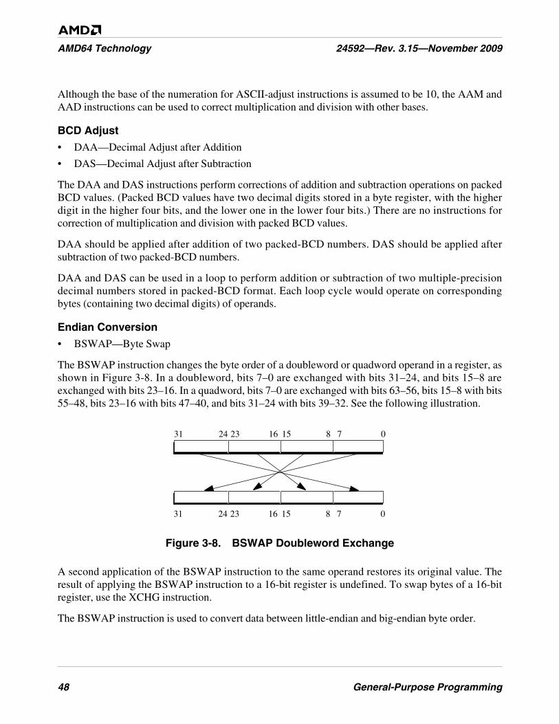
48 General-Purpose Programming
AMD64 Technology 24592—Rev. 3.15—November 2009
Although the base of the numeration for ASCII-adjust instructions is assumed to be 10, the AAM andAAD instructions can be used to correct multiplication and division with other bases.
BCD Adjust
• DAA—Decimal Adjust after Addition
• DAS—Decimal Adjust after Subtraction
The DAA and DAS instructions perform corrections of addition and subtraction operations on packedBCD values. (Packed BCD values have two decimal digits stored in a byte register, with the higherdigit in the higher four bits, and the lower one in the lower four bits.) There are no instructions forcorrection of multiplication and division with packed BCD values.
DAA should be applied after addition of two packed-BCD numbers. DAS should be applied aftersubtraction of two packed-BCD numbers.
DAA and DAS can be used in a loop to perform addition or subtraction of two multiple-precisiondecimal numbers stored in packed-BCD format. Each loop cycle would operate on correspondingbytes (containing two decimal digits) of operands.
Endian Conversion
• BSWAP—Byte Swap
The BSWAP instruction changes the byte order of a doubleword or quadword operand in a register, asshown in Figure 3-8. In a doubleword, bits 7–0 are exchanged with bits 31–24, and bits 15–8 areexchanged with bits 23–16. In a quadword, bits 7–0 are exchanged with bits 63–56, bits 15–8 with bits55–48, bits 23–16 with bits 47–40, and bits 31–24 with bits 39–32. See the following illustration.
Figure 3-8. BSWAP Doubleword Exchange
A second application of the BSWAP instruction to the same operand restores its original value. Theresult of applying the BSWAP instruction to a 16-bit register is undefined. To swap bytes of a 16-bitregister, use the XCHG instruction.
The BSWAP instruction is used to convert data between little-endian and big-endian byte order.
07815162331 24
07815162331 24
General-Purpose Programming 49
24592—Rev. 3.15—November 2009 AMD64 Technology
3.3.4 Load Segment Registers
These instructions load segment registers.
• LDS, LES, LFS, LGS, LSS—Load Far Pointer
• MOV segReg—Move Segment Register
• POP segReg—Pop Stack Into Segment Register
The LDS, LES, LFD, LGS, and LSS instructions atomically (with respect to interrupts only, notcontending memory accesses) load the two parts of a far pointer into a segment register and a general-purpose register. A far pointer is a 16-bit segment selector and a 16-bit or 32-bit offset. The load copiesthe segment-selector portion of the pointer from memory into the segment register and the offsetportion of the pointer from memory into a general-purpose register.
The effective operand size determines the size of the offset loaded by the LDS, LES, LFD, LGS, andLSS instructions. The instructions load not only the software-visible segment selector into the segmentregister, but they also cause the hardware to load the associated segment-descriptor information intothe software-invisible (hidden) portion of that segment register.
The MOV segReg and POP segReg instructions load a segment selector from a general-purposeregister or memory (for MOV segReg) or from the top of the stack (for POP segReg) to a segmentregister. These instructions not only load the software-visible segment selector into the segmentregister but also cause the hardware to load the associated segment-descriptor information into thesoftware-invisible (hidden) portion of that segment register.
In 64-bit mode, the POP DS, POP ES, and POP SS instructions are invalid.
3.3.5 Load Effective Address
• LEA—Load Effective Address
The LEA instruction calculates and loads the effective address (offset within a given segment) of asource operand and places it in a general-purpose register.
LEA is related to MOV, which copies data from a memory location to a register, but LEA takes theaddress of the source operand, whereas MOV takes the contents of the memory location specified bythe source operand. In the simplest cases, LEA can be replaced with MOV. For example:
lea eax, [ebx]
has the same effect as:
mov eax, ebx
However, LEA allows software to use any valid addressing mode for the source operand. For example:
lea eax, [ebx+edi]
loads the sum of EBX and EDI registers into the EAX register. This could not be accomplished by asingle MOV instruction.

50 General-Purpose Programming
AMD64 Technology 24592—Rev. 3.15—November 2009
LEA has a limited capability to perform multiplication of operands in general-purpose registers usingscaled-index addressing. For example:
lea eax, [ebx+ebx*8]
loads the value of the EBX register, multiplied by 9, into the EAX register.
3.3.6 Arithmetic
The arithmetic instructions perform basic arithmetic operations, such as addition, subtraction,multiplication, and division on integer operands.
Add and Subtract
• ADC—Add with Carry
• ADD—Signed or Unsigned Add
• SBB—Subtract with Borrow
• SUB—Subtract
• NEG—Two’s Complement Negation
The ADD instruction performs addition of two integer operands. There are opcodes that add animmediate value to a byte, word, doubleword, or quadword register or a memory location. In theseopcodes, if the size of the immediate is smaller than that of the destination, the immediate is first sign-extended to the size of the destination operand. The arithmetic flags (OF, SF, ZF, AF, CF, PF) are setaccording to the resulting value of the destination operand.
The ADC instruction performs addition of two integer operands, plus 1 if the carry flag (CF) is set.
The SUB instruction performs subtraction of two integer operands.
The SBB instruction performs subtraction of two integer operands, and it also subtracts an additional 1if the carry flag is set.
The ADC and SBB instructions simplify addition and subtraction of multiple-precision integeroperands, because they correctly handle carries (and borrows) between parts of a multiple-precisionoperand.
The NEG instruction performs negation of an integer operand. The value of the operand is replacedwith the result of subtracting the operand from zero.
Multiply and Divide
• MUL—Multiply Unsigned
• IMUL—Signed Multiply
• DIV—Unsigned Divide
• IDIV—Signed Divide
General-Purpose Programming 51
24592—Rev. 3.15—November 2009 AMD64 Technology
The MUL instruction performs multiplication of unsigned integer operands. The size of operands canbe byte, word, doubleword, or quadword. The product is stored in a destination which is double thesize of the source operands (multiplicand and factor).
The MUL instruction's mnemonic has only one operand, which is a factor. The multiplicand operand isalways assumed to be an accumulator register. For byte-sized multiplies, AL contains the multiplicand,and the result is stored in AX. For word-sized, doubleword-sized, and quadword-sized multiplies, rAXcontains the multiplicand, and the result is stored in rDX and rAX.
The IMUL instruction performs multiplication of signed integer operands. There are forms of theIMUL instruction with one, two, and three operands, and it is thus more powerful than the MULinstruction. The one-operand form of the IMUL instruction behaves similarly to the MUL instruction,except that the operands and product are signed integer values. In the two-operand form of IMUL, themultiplicand and product use the same register (the first operand), and the factor is specified in thesecond operand. In the three-operand form of IMUL, the product is stored in the first operand, themultiplicand is specified in the second operand, and the factor is specified in the third operand.
The DIV instruction performs division of unsigned integers. The instruction divides a double-sizeddividend in AH:AL or rDX:rAX by the divisor specified in the operand of the instruction. It stores thequotient in AL or rAX and the remainder in AH or rDX.
The IDIV instruction performs division of signed integers. It behaves similarly to DIV, with theexception that the operands are treated as signed integer values.
Division is the slowest of all integer arithmetic operations and should be avoided wherever possible.One possibility for improving performance is to replace division with multiplication, such as byreplacing i/j/k with i/(j*k). This replacement is possible if no overflow occurs during the computationof the product. This can be determined by considering the possible ranges of the divisors.
Increment and Decrement
• DEC—Decrement by 1
• INC—Increment by 1
The INC and DEC instructions are used to increment and decrement, respectively, an integer operandby one. For both instructions, an operand can be a byte, word, doubleword, or quadword register ormemory location.
These instructions behave in all respects like the corresponding ADD and SUB instructions, with thesecond operand as an immediate value equal to 1. The only exception is that the carry flag (CF) is notaffected by the INC and DEC instructions.
Apart from their obvious arithmetic uses, the INC and DEC instructions are often used to modifyaddresses of operands. In this case it can be desirable to preserve the value of the carry flag (to use itlater), so these instructions do not modify the carry flag.
52 General-Purpose Programming
AMD64 Technology 24592—Rev. 3.15—November 2009
3.3.7 Rotate and Shift
The rotate and shift instructions perform cyclic rotation or non-cyclic shift, by a given number of bits(called the count), in a given byte-sized, word-sized, doubleword-sized or quadword-sized operand.
When the count is greater than 1, the result of the rotate and shift instructions can be considered as aniteration of the same 1-bit operation by count number of times. Because of this, the descriptions belowdescribe the result of 1-bit operations.
The count can be 1, the value of the CL register, or an immediate 8-bit value. To avoid redundancy andmake rotation and shifting quicker, the count is masked to the 5 or 6 least-significant bits, dependingon the effective operand size, so that its value does not exceed 31 or 63 before the rotation or shift takesplace.
Rotate
• RCL—Rotate Through Carry Left
• RCR—Rotate Through Carry Right
• ROL—Rotate Left
• ROR—Rotate Right
The RCx instructions rotate the bits of the first operand to the left or right by the number of bitsspecified by the source (count) operand. The bits rotated out of the destination operand are rotated intothe carry flag (CF) and the carry flag is rotated into the opposite end of the first operand.
The ROx instructions rotate the bits of the first operand to the left or right by the number of bitsspecified by the source operand. Bits rotated out are rotated back in at the opposite end. The value ofthe CF flag is determined by the value of the last bit rotated out. In single-bit left-rotates, the overflowflag (OF) is set to the XOR of the CF flag after rotation and the most-significant bit of the result. Insingle-bit right-rotates, the OF flag is set to the XOR of the two most-significant bits. Thus, in bothcases, the OF flag is set to 1 if the single-bit rotation changed the value of the most-significant bit (signbit) of the operand. The value of the OF flag is undefined for multi-bit rotates.
Bit-rotation instructions provide many ways to reorder bits in an operand. This can be useful, forexample, in character conversion, including cryptography techniques.
Shift
• SAL—Shift Arithmetic Left
• SAR—Shift Arithmetic Right
• SHL—Shift Left
• SHR—Shift Right
• SHLD—Shift Left Double
• SHRD—Shift Right Double
General-Purpose Programming 53
24592—Rev. 3.15—November 2009 AMD64 Technology
The SHx instructions (including SHxD) perform shift operations on unsigned operands. The SAxinstructions operate with signed operands.
SHL and SAL instructions effectively perform multiplication of an operand by a power of 2, in whichcase they work as more-efficient alternatives to the MUL instruction. Similarly, SHR and SARinstructions can be used to divide an operand (signed or unsigned, depending on the instruction used)by a power of 2.
Although the SAR instruction divides the operand by a power of 2, the behavior is different from theIDIV instruction. For example, shifting –11 (FFFFFFF5h) by two bits to the right (i.e. divide –11 by4), gives a result of FFFFFFFDh, or –3, whereas the IDIV instruction for dividing –11 by 4 gives aresult of –2. This is because the IDIV instruction rounds off the quotient to zero, whereas the SARinstruction rounds off the remainder to zero for positive dividends, and to negative infinity for negativedividends. This means that, for positive operands, SAR behaves like the corresponding IDIVinstruction, and for negative operands, it gives the same result if and only if all the shifted-out bits arezeroes, and otherwise the result is smaller by 1.
The SAR instruction treats the most-significant bit (msb) of an operand in a special way: the msb (thesign bit) is not changed, but is copied to the next bit, preserving the sign of the result. The least-significant bit (lsb) is shifted out to the CF flag. In the SAL instruction, the msb is shifted out to CFflag, and the lsb is cleared to 0.
The SHx instructions perform logical shift, i.e. without special treatment of the sign bit. SHL is thesame as SAL (in fact, their opcodes are the same). SHR copies 0 into the most-significant bit, andshifts the least-significant bit to the CF flag.
The SHxD instructions perform a double shift. These instructions perform left and right shift of thedestination operand, taking the bits to copy into the most-significant bit (for the SHRD instruction) orinto the least-significant bit (for the SHLD instruction) from the source operand. These instructionsbehave like SHx, but use bits from the source operand instead of zero bits to shift into the destinationoperand. The source operand is not changed.
3.3.8 Compare and Test
The compare and test instructions perform arithmetic and logical comparison of operands and setcorresponding flags, depending on the result of comparison. These instruction are used in conjunctionwith conditional instructions such as Jcc or SETcc to organize branching and conditionally executingblocks in programs. Assembler equivalents of conditional operators in high-level languages(do…while, if…then…else, and similar) also include compare and test instructions.
Compare
• CMP—Compare
The CMP instruction performs subtraction of the second operand (source) from the first operand(destination), like the SUB instruction, but it does not store the resulting value in the destinationoperand. It leaves both operands intact. The only effect of the CMP instruction is to set or clear thearithmetic flags (OF, SF, ZF, AF, CF, PF) according to the result of subtraction.
54 General-Purpose Programming
AMD64 Technology 24592—Rev. 3.15—November 2009
The CMP instruction is often used together with the conditional jump instructions (Jcc), conditionalSET instructions (SETcc) and other instructions such as conditional loops (LOOPcc) whose behaviordepends on flag state.
Test
• TEST—Test Bits
The TEST instruction is in many ways similar to the AND instruction: it performs logical conjunctionof the corresponding bits of both operands, but unlike the AND instruction it leaves the operandsunchanged. The purpose of this instruction is to update flags for further testing.
The TEST instruction is often used to test whether one or more bits in an operand are zero. In this case,one of the instruction operands would contain a mask in which all bits are cleared to zero except thebits being tested. For more advanced bit testing and bit modification, use the BTx instructions.
Bit Scan
• BSF—Bit Scan Forward
• BSR—Bit Scan Reverse
The BSF and BSR instructions search a source operand for the least-significant (BSF) or most-significant (BSR) bit that is set to 1. If a set bit is found, its bit index is loaded into the destinationoperand, and the zero flag (ZF) is set. If no set bit is found, the zero flag is cleared and the contents ofthe destination are undefined.
Population and Leading Zero Counts
• POPCNT—Bit Population Count
• LZCNT—Count Leading Zeros
The POPCNT instruction counts the number of bits having a value of 1 in the source operand andplaces the total in the destination register, while the LZCNT instruction counts the number of leadingzero bits in a general purpose register or memory source operand.
Bit Test
• BT—Bit Test
• BTC—Bit Test and Complement
• BTR—Bit Test and Reset
• BTS—Bit Test and Set
The BTx instructions copy a specified bit in the first operand to the carry flag (CF) and leave the sourcebit unchanged (BT), or complement the source bit (BTC), or clear the source bit to 0 (BTR), or set thesource bit to 1 (BTS).
These instructions are useful for implementing semaphore arrays. Unlike the XCHG instruction, theBTx instructions set the carry flag, so no additional test or compare instruction is needed. Also,

General-Purpose Programming 55
24592—Rev. 3.15—November 2009 AMD64 Technology
because these instructions operate directly on bits rather than larger data types, the semaphore arrayscan be smaller than is possible when using XCHG. In such semaphore applications, bit-testinstructions should be preceded by the LOCK prefix.
Set Byte on Condition
• SETcc—Set Byte if condition
The SETcc instructions store a 1 or 0 value to their byte operand depending on whether their condition(represented by certain rFLAGS bits) is true or false, respectively. Table 3-5 shows the rFLAGS valuesrequired for each SETcc instruction.
Table 3-5. rFLAGS for SETcc Instructions
Mnemonic Required Flag State Description
SETO OF = 1 Set byte if overflow
SETNO OF = 0 Set byte if not overflow
SETBSETCSETNAE
CF = 1Set byte if belowSet byte if carrySet byte if not above or equal (unsigned operands)
SETAESETNBSETNC
CF = 0Set byte if above or equalSet byte if not belowSet byte if not carry (unsigned operands)
SETESETZ
ZF = 1Set byte if equalSet byte if zero
SETNESETNZ
ZF = 0Set byte if not equalSet byte if not zero
SETBESETNA
CF = 1 or ZF = 1Set byte if below or equalSet byte if not above (unsigned operands)
SETASETNBE
CF = 0 and ZF = 0Set byte if not below or equalSet byte if not below or equal (unsigned operands)
SETS SF = 1 Set byte if sign
SETNS SF = 0 Set byte if not sign
SETPSETPE
PF = 1Set byte if paritySet byte if parity even
SETNPSETPO
PF = 0Set byte if not paritySet byte if parity odd
SETLSETNGE
SF <> OFSet byte if lessSet byte if not greater or equal (signed operands)
SETGESETNL
SF = OFSet byte if greater or equalSet byte if not less (signed operands)
SETLESETNG
ZF = 1 or SF <> OFSet byte if less or equalSet byte if not greater (signed operands)
SETGSETNLE
ZF = 0 and SF = OFSet byte if greaterSet byte if not less or equal (signed operands)
56 General-Purpose Programming
AMD64 Technology 24592—Rev. 3.15—November 2009
SETcc instructions are often used to set logical indicators. Like CMOVcc instructions (page 42),SETcc instructions can replace two instructions—a conditional jump and a move. Replacingconditional jumps with conditional sets can help avoid branch-prediction penalties that may be causedby conditional jumps.
If the logical value True (logical 1) is represented in a high-level language as an integer with all bits setto 1, software can accomplish such representation by first executing the opposite SETcc instruction—for example, the opposite of SETZ is SETNZ—and then decrementing the result.
Bounds
• BOUND—Check Array Bounds
The BOUND instruction checks whether the value of the first operand, a signed integer index into anarray, is within the minimal and maximal bound values pointed to by the second operand. The valuesof array bounds are often stored at the beginning of the array. If the bounds of the range are exceeded,the processor generates a bound-range exception.
The primary disadvantage of using the BOUND instruction is its use of the time-consuming exceptionmechanism to signal a failure of the bounds test.
3.3.9 Logical
The logical instructions perform bitwise operations.
• AND—Logical AND
• OR—Logical OR
• XOR—Exclusive OR
• NOT—One’s Complement Negation
The AND, OR, and XOR instructions perform their respective logical operations on the correspondingbits of both operands and store the result in the first operand. The CF flag and OF flag are cleared to 0,and the ZF flag, SF flag, and PF flag are set according to the resulting value of the first operand.
The NOT instruction performs logical inversion of all bits of its operand. Each zero bit becomes oneand vice versa. All flags remain unchanged.
Apart from performing logical operations, AND and OR can test a register for a zero or non-zerovalue, sign (negative or positive), and parity status of its lowest byte. To do this, both operands must bethe same register. The XOR instruction with two identical operands is an efficient way of loading thevalue 0 into a register.
3.3.10 String
The string instructions perform common string operations such as copying, moving, comparing, orsearching strings. These instructions are widely used for processing text.
General-Purpose Programming 57
24592—Rev. 3.15—November 2009 AMD64 Technology
Compare Strings
• CMPS—Compare Strings
• CMPSB—Compare Strings by Byte
• CMPSW—Compare Strings by Word
• CMPSD—Compare Strings by Doubleword
• CMPSQ—Compare Strings by Quadword
The CMPSx instructions compare the values of two implicit operands of the same size located atseg:[rSI] and ES:[rDI]. After the copy, both the rSI and rDI registers are auto-incremented (if the DFflag is 0) or auto-decremented (if the DF flag is 1).
Scan String
• SCAS—Scan String
• SCASB—Scan String as Bytes
• SCASW—Scan String as Words
• SCASD—Scan String as Doubleword
• SCASQ—Scan String as Quadword
The SCASx instructions compare the values of a memory operands in ES:rDI to a value of the samesize in the AL/rAX register. Bits in rFLAGS are set to indicate the outcome of the comparison. Afterthe comparison, the rDI register is auto-incremented (if the DF flag is 0) or auto-decremented (if theDF flag is 1).
Move String
• MOVS—Move String
• MOVSB—Move String Byte
• MOVSW—Move String Word
• MOVSD—Move String Doubleword
• MOVSQ—Move String Quadword
The MOVSx instructions copy an operand from the memory location seg:[rSI] to the memory locationES:[rDI]. After the copy, both the rSI and rDI registers are auto-incremented (if the DF flag is 0) orauto-decremented (if the DF flag is 1).
Load String
• LODS—Load String
• LODSB—Load String Byte
• LODSW—Load String Word
• LODSD—Load String Doubleword
• LODSQ—Load String Quadword
58 General-Purpose Programming
AMD64 Technology 24592—Rev. 3.15—November 2009
The LODSx instructions load a value from the memory location seg:[rSI] to the accumulator register(AL or rAX). After the load, the rSI register is auto-incremented (if the DF flag is 0) or auto-decremented (if the DF flag is 1).
Store String
• STOS—Store String
• STOSB—Store String Bytes
• STOSW—Store String Words
• STOSD—Store String Doublewords
• STOSQ—Store String Quadword
The STOSx instructions copy the accumulator register (AL or rAX) to a memory location ES:[rDI].After the copy, the rDI register is auto-incremented (if the DF flag is 0) or auto-decremented (if the DFflag is 1).
3.3.11 Control Transfer
Control-transfer instructions, or branches, are used to iterate through loops and move throughconditional program logic.
Jump
• JMP—Jump
JMP performs an unconditional jump to the specified address. There are several ways to specify thetarget address.
• Relative Short Jump and Relative Near Jump—The target address is determined by adding an 8-bit(short jump) or 16-bit or 32-bit (near jump) signed displacement to the rIP of the instructionfollowing the JMP. The jump is performed within the current code segment (CS).
• Register-Indirect and Memory-Indirect Near Jump—The target rIP value is contained in a registeror in a memory location. The jump is performed within the current CS.
• Direct Far Jump—For all far jumps, the target address is outside the current code segment. Here,the instruction specifies the 16-bit target-address code segment and the 16-bit or 32-bit offset as animmediate value. The direct far jump form is invalid in 64-bit mode.
• Memory-Indirect Far Jump—For this form, the target address (CS:rIP) is in a address outside thecurrent code segment. A 32-bit or 48-bit far pointer in a specified memory location points to thetarget address.
The size of the target rIP is determined by the effective operand size for the JMP instruction.
For far jumps, the target selector can specify a code-segment selector, in which case it is loaded intoCS, and a 16-bit or 32-bit target offset is loaded into rIP. The target selector can also be a call-gateselector or a task-state-segment (TSS) selector, used for performing task switches. In these cases, the
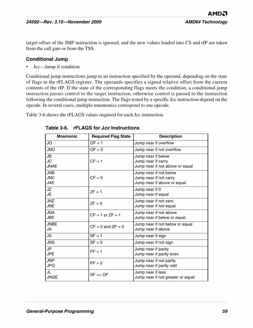
General-Purpose Programming 59
24592—Rev. 3.15—November 2009 AMD64 Technology
target offset of the JMP instruction is ignored, and the new values loaded into CS and rIP are takenfrom the call gate or from the TSS.
Conditional Jump
• Jcc—Jump if condition
Conditional jump instructions jump to an instruction specified by the operand, depending on the stateof flags in the rFLAGS register. The operands specifies a signed relative offset from the currentcontents of the rIP. If the state of the corresponding flags meets the condition, a conditional jumpinstruction passes control to the target instruction, otherwise control is passed to the instructionfollowing the conditional jump instruction. The flags tested by a specific Jcc instruction depend on theopcode. In several cases, multiple mnemonics correspond to one opcode.
Table 3-6 shows the rFLAGS values required for each Jcc instruction.
Table 3-6. rFLAGS for Jcc Instructions
Mnemonic Required Flag State Description
JO OF = 1 Jump near if overflow
JNO OF = 0 Jump near if not overflow
JBJCJNAE
CF = 1Jump near if belowJump near if carryJump near if not above or equal
JNBJNCJAE
CF = 0Jump near if not belowJump near if not carryJump near if above or equal
JZJE
ZF = 1Jump near if 0Jump near if equal
JNZJNE
ZF = 0Jump near if not zeroJump near if not equal
JNAJBE
CF = 1 or ZF = 1Jump near if not aboveJump near if below or equal
JNBEJA
CF = 0 and ZF = 0Jump near if not below or equalJump near if above
JS SF = 1 Jump near if sign
JNS SF = 0 Jump near if not sign
JPJPE
PF = 1Jump near if parityJump near if parity even
JNPJPO
PF = 0Jump near if not parityJump near if parity odd
JLJNGE
SF <> OFJump near if lessJump near if not greater or equal
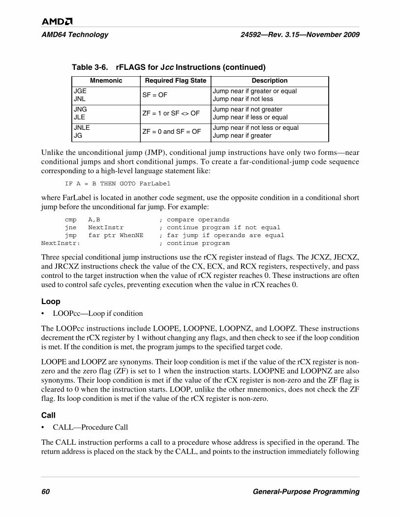
60 General-Purpose Programming
AMD64 Technology 24592—Rev. 3.15—November 2009
Unlike the unconditional jump (JMP), conditional jump instructions have only two forms—nearconditional jumps and short conditional jumps. To create a far-conditional-jump code sequencecorresponding to a high-level language statement like:
IF A = B THEN GOTO FarLabel
where FarLabel is located in another code segment, use the opposite condition in a conditional shortjump before the unconditional far jump. For example:
cmp A,B ; compare operandsjne NextInstr ; continue program if not equaljmp far ptr WhenNE ; far jump if operands are equal
NextInstr: ; continue program
Three special conditional jump instructions use the rCX register instead of flags. The JCXZ, JECXZ,and JRCXZ instructions check the value of the CX, ECX, and RCX registers, respectively, and passcontrol to the target instruction when the value of rCX register reaches 0. These instructions are oftenused to control safe cycles, preventing execution when the value in rCX reaches 0.
Loop
• LOOPcc—Loop if condition
The LOOPcc instructions include LOOPE, LOOPNE, LOOPNZ, and LOOPZ. These instructionsdecrement the rCX register by 1 without changing any flags, and then check to see if the loop conditionis met. If the condition is met, the program jumps to the specified target code.
LOOPE and LOOPZ are synonyms. Their loop condition is met if the value of the rCX register is non-zero and the zero flag (ZF) is set to 1 when the instruction starts. LOOPNE and LOOPNZ are alsosynonyms. Their loop condition is met if the value of the rCX register is non-zero and the ZF flag iscleared to 0 when the instruction starts. LOOP, unlike the other mnemonics, does not check the ZFflag. Its loop condition is met if the value of the rCX register is non-zero.
Call
• CALL—Procedure Call
The CALL instruction performs a call to a procedure whose address is specified in the operand. Thereturn address is placed on the stack by the CALL, and points to the instruction immediately following
JGEJNL
SF = OFJump near if greater or equalJump near if not less
JNGJLE
ZF = 1 or SF <> OFJump near if not greaterJump near if less or equal
JNLEJG
ZF = 0 and SF = OFJump near if not less or equalJump near if greater
Table 3-6. rFLAGS for Jcc Instructions (continued)
Mnemonic Required Flag State Description
General-Purpose Programming 61
24592—Rev. 3.15—November 2009 AMD64 Technology
the CALL. When the called procedure finishes execution and is exited using a return instruction,control is transferred to the return address saved on the stack.
The CALL instruction has the same forms as the JMP instruction, except that CALL lacks the short-relative (1-byte offset) form.
• Relative Near Call—These specify an offset relative to the instruction following the CALLinstruction. The operand is an immediate 16-bit or 32-bit offset from the called procedure, withinthe same code segment.
• Register-Indirect and Memory-Indirect Near Call—These specify a target address contained in aregister or memory location.
• Direct Far Call—These specify a target address outside the current code segment. The address ispointed to by a 32-bit or 48-bit far-pointer specified by the instruction, which consists of a 16-bitcode selector and a 16-bit or 32-bit offset. The direct far call form is invalid in 64-bit mode.
• Memory-Indirect Far Call—These specify a target address outside the current code segment. Theaddress is pointed to by a 32-bit or 48-bit far pointer in a specified memory location.
The size of the rIP is in all cases determined by the operand-size attribute of the CALL instruction.CALLs push the return address to the stack. The data pushed on the stack depends on whether a near orfar call is performed, and whether a privilege change occurs. See Section 3.7.5, “Procedure Calls,” onpage 79 for further information.
For far CALLs, the selector portion of the target address can specify a code-segment selector (in whichcase the selector is loaded into the CS register), or a call-gate selector, (used for calls that changeprivilege level), or a task-state-segment (TSS) selector (used for task switches). In the latter two cases,the offset portion of the CALL instruction’s target address is ignored, and the new values loaded intoCS and rIP are taken from the call gate or TSS.
Return
• RET—Return from Call
The RET instruction returns from a procedure originally called using the CALL instruction. CALLplaces a return address (which points to the instruction following the CALL) on the stack. RET takesthe return address from the stack and transfers control to the instruction located at that address.
Like CALL instructions, RET instructions have both a near and far form. An optional immediateoperand for the RET specifies the number of bytes to be popped from the procedure stack forparameters placed on the stack. See Section 3.7.6, “Returning from Procedures,” on page 81 foradditional information.
Interrupts and Exceptions.
• INT—Interrupt to Vector Number
• INTO—Interrupt to Overflow Vector
• IRET—Interrupt Return Word
62 General-Purpose Programming
AMD64 Technology 24592—Rev. 3.15—November 2009
• IRETD—Interrupt Return Doubleword
• IRETQ—Interrupt Return Quadword
The INT instruction implements a software interrupt by calling an interrupt handler. The operand ofthe INT instruction is an immediate byte value specifying an index in the interrupt descriptor table(IDT), which contains addresses of interrupt handlers (see Section 3.7.10, “Interrupts and Exceptions,”on page 86 for further information on the IDT).
The 1-byte INTO instruction calls interrupt 4 (the overflow exception, #OF), if the overflow flag inRFLAGS is set to 1, otherwise it does nothing. Signed arithmetic instructions can be followed by theINTO instruction if the result of the arithmetic operation can potentially overflow. (The 1-byte INT 3instruction is considered a system instruction and is therefore not described in this volume).
IRET, IRETD, and IRETQ perform a return from an interrupt handler. The mnemonic specifies theoperand size, which determines the format of the return addresses popped from the stack (IRET for 16-bit operand size, IRETD for 32-bit operand size, and IRETQ for 64-bit operand size). However, someassemblers can use the IRET mnemonic for all operand sizes. Actions performed by IRET are oppositeto actions performed by an interrupt or exception. In real and protected mode, IRET pops the rIP, CS,and RFLAGS contents from the stack, and it pops SS:rSP if a privilege-level change occurs or if itexecutes from 64-bit mode. In protected mode, the IRET instruction can also cause a task switch if thenested task (NT) bit in the RFLAGS register is set. For details on using IRET to switch tasks, see “TaskManagement” in Volume 2.
3.3.12 Flags
The flags instructions read and write bits of the RFLAGS register that are visible to applicationsoftware. “Flags Register” on page 33 illustrates the RFLAGS register.
Push and Pop Flags
• POPF—Pop to FLAGS Word
• POPFD—Pop to EFLAGS Doubleword
• POPFQ—Pop to RFLAGS Quadword
• PUSHF—Push FLAGS Word onto Stack
• PUSHFD—Push EFLAGS Doubleword onto Stack
• PUSHFQ—Push RFLAGS Quadword onto Stack
The push and pop flags instructions copy data between the rFLAGS register and the stack. POPF andPUSHF copy 16 bits of data between the stack and the FLAGS register (the low 16 bits of EFLAGS),leaving the high 48 bits of RFLAGS unchanged. POPFD and PUSHFD copy 32 bits between the stackand the RFLAGS register. POPFQ and PUSHFQ copy 64 bits between the stack and the RFLAGSregister. Only the bits illustrated in Figure 3-5 on page 34 are affected. Reserved bits and bits whosewritability is prevented by the current values of system flags, current privilege level (CPL), or currentoperating mode, are unaffected by the POPF, POPFQ, and POPFD instructions.
General-Purpose Programming 63
24592—Rev. 3.15—November 2009 AMD64 Technology
For details on stack operations, see “Control Transfers” on page 76.
Set and Clear Flags
• CLC—Clear Carry Flag
• CMC—Complement Carry Flag
• STC—Set Carry Flag
• CLD—Clear Direction Flag
• STD—Set Direction Flag
• CLI—Clear Interrupt Flag
• STI—Set Interrupt Flag
These instructions change the value of a flag in the rFLAGS register that is visible to applicationsoftware. Each instruction affects only one specific flag.
The CLC, CMC, and STC instructions change the carry flag (CF). CLC clears the flag to 0, STC setsthe flag to 1, and CMC inverts the flag. These instructions are useful prior to executing instructionswhose behavior depends on the CF flag—for example, shift and rotate instructions.
The CLD and STD instructions change the direction flag (DF) and influence the function of stringinstructions (CMPSx, SCASx, MOVSx, LODSx, STOSx, INSx, OUTSx). CLD clears the flag to 0,and STD sets the flag to 1. A cleared DF flag indicates the forward direction in string sequences, and aset DF flag indicates the backward direction. Thus, in string instructions, the rSI and/or rDI registervalues are auto-incremented when DF = 0 and auto-decremented when DF = 1.
Two other instructions, CLI and STI, clear and set the interrupt flag (IF). CLI clears the flag, causingthe processor to ignore external maskable interrupts. STI sets the flag, allowing the processor torecognize maskable external interrupts. These instructions are used primarily by system software—especially, interrupt handlers—and are described in “Exceptions and Interrupts” in Volume 2.
Load and Store Flags
• LAHF—Load Status Flags into AH Register
• SAHF—Store AH into Flags
LAHF loads the lowest byte of the RFLAGS register into the AH register. This byte contains the carryflag (CF), parity flag (PF), auxiliary flag (AF), zero flag (ZF), and sign flag (SF). SAHF stores the AHregister into the lowest byte of the RFLAGS register.
3.3.13 Input/Output
The I/O instructions perform reads and writes of bytes, words, and doublewords from and to the I/Oaddress space. This address space can be used to access and manage external devices, and isindependent of the main-memory address space. By contrast, memory-mapped I/O uses the main-memory address space and is accessed using the MOV instructions rather than the I/O instructions.
64 General-Purpose Programming
AMD64 Technology 24592—Rev. 3.15—November 2009
When operating in legacy protected mode or in long mode, the RFLAGS register’s I/O privilege level(IOPL) field and the I/O-permission bitmap in the current task-state segment (TSS) are used to controlaccess to the I/O addresses (called I/O ports). See “Input/Output” on page 90 for further information.
General I/O
• IN—Input from Port
• OUT—Output to Port
The IN instruction reads a byte, word, or doubleword from the I/O port address specified by the sourceoperand, and loads it into the accumulator register (AL or eAX). The source operand can be animmediate byte or the DX register.
The OUT instruction writes a byte, word, or doubleword from the accumulator register (AL or eAX) tothe I/O port address specified by the destination operand, which can be either an immediate byte or theDX register.
If the I/O port address is specified with an immediate operand, the range of port addresses accessibleby the IN and OUT instructions is limited to ports 0 through 255. If the I/O port address is specified bya value in the DX register, all 65,536 ports are accessible.
String I/O
• INS—Input String
• INSB—Input String Byte
• INSW—Input String Word
• INSD—Input String Doubleword
• OUTS—Output String
• OUTSB—Output String Byte
• OUTSW—Output String Word
• OUTSD—Output String Doubleword
The INSx instructions (INSB, INSW, INSD) read a byte, word, or doubleword from the I/O portspecified by the DX register, and load it into the memory location specified by ES:[rDI].
The OUTSx instructions (OUTSB, OUTSW, OUTSD) write a byte, word, or doubleword from animplicit memory location specified by seg:[rSI], to the I/O port address stored in the DX register.
The INSx and OUTSx instructions are commonly used with a repeat prefix to transfer blocks of data.The memory pointer address is not incremented or decremented. This usage is intended for peripheralI/O devices that are expecting a stream of data.
3.3.14 Semaphores
The semaphore instructions support the implementation of reliable signaling between processors in amulti-processing environment, usually for the purpose of sharing resources.
General-Purpose Programming 65
24592—Rev. 3.15—November 2009 AMD64 Technology
• CMPXCHG—Compare and Exchange
• CMPXCHG8B—Compare and Exchange Eight Bytes
• CMPXCHG16B—Compare and Exchange Sixteen Bytes
• XADD—Exchange and Add
• XCHG—Exchange
The CMPXCHG instruction compares a value in the AL or rAX register with the first (destination)operand, and sets the arithmetic flags (ZF, OF, SF, AF, CF, PF) according to the result. If the comparedvalues are equal, the source operand is loaded into the destination operand. If they are not equal, thefirst operand is loaded into the accumulator. CMPXCHG can be used to try to intercept a semaphore,i.e. test if its state is free, and if so, load a new value into the semaphore, making its state busy. The testand load are performed atomically, so that concurrent processes or threads which use the semaphore toaccess a shared object will not conflict.
The CMPXCHG8B instruction compares the 64-bit values in the EDX:EAX registers with a 64-bitmemory location. If the values are equal, the zero flag (ZF) is set, and the ECX:EBX value is copied tothe memory location. Otherwise, the ZF flag is cleared, and the memory value is copied to EDX:EAX.
The CMPXCHG16B instruction compares the 128-bit value in the RDX:RAX and RCX:RBXregisters with a 128-bit memory location. If the values are equal, the zero flag (ZF) is set, and theRCX:RBX value is copied to the memory location. Otherwise, the ZF flag is cleared, and the memoryvalue is copied to rDX:rAX.
The XADD instruction exchanges the values of its two operands, then it stores their sum in the first(destination) operand.
A LOCK prefix can be used to make the CMPXCHG, CMPXCHG8B and XADD instructions atomicif one of the operands is a memory location.
The XCHG instruction exchanges the values of its two operands. If one of the operands is in memory,the processor’s bus-locking mechanism is engaged automatically during the exchange, whether or notthe LOCK prefix is used.
3.3.15 Processor Information
• CPUID—Processor Identification
The CPUID instruction returns information about the processor implementation and its support forinstruction subsets and architectural features. Software operating at any privilege level can execute theCPUID instruction to read this information. After the information is read, software can selectprocedures that optimize performance for a particular hardware implementation.
Some processor implementations may not support the CPUID instruction. Support for the CPUIDinstruction is determined by testing the RFLAGS.ID bit. If software can write this bit, then the CPUIDinstruction is supported by the processor implementation. Otherwise, execution of CPUID results in aninvalid-opcode exception.
66 General-Purpose Programming
AMD64 Technology 24592—Rev. 3.15—November 2009
See “Feature Detection” on page 74 for details about using the CPUID instruction. For a fulldescription of the CPUID instruction and its function codes, see “CPUID” in Volume 3 and theCPUID Specification, order# 25481.
3.3.16 Cache and Memory Management
Applications can use the cache and memory-management instructions to control memory reads andwrites to influence the caching of read/write data. “Memory Optimization” on page 92 describes howthese instructions interact with the memory subsystem.
• LFENCE—Load Fence
• SFENCE—Store Fence
• MFENCE—Memory Fence
• PREFETCHlevel—Prefetch Data to Cache Level level
• PREFETCH—Prefetch L1 Data-Cache Line
• PREFETCHW—Prefetch L1 Data-Cache Line for Write
• CLFLUSH—Cache Line Invalidate
The LFENCE, SFENCE, and MFENCE instructions can be used to force ordering on memoryaccesses. The order of memory accesses can be important when the reads and writes are to a memory-mapped I/O device, and in multiprocessor environments where memory synchronization is required.LFENCE affects ordering on memory reads, but not writes. SFENCE affects ordering on memorywrites, but not reads. MFENCE orders both memory reads and writes. These instructions do not takeoperands. They are simply inserted between the memory references that are to be ordered. For detailsabout the fence instructions, see “Forcing Memory Order” on page 94.
The PREFETCHlevel, PREFETCH, and PREFETCHW instructions load data from memory into oneor more cache levels. PREFETCHlevel loads a memory block into a specified level in the data-cachehierarchy (including a non-temporal caching level). The size of the memory block is implementationdependent. PREFETCH loads a cache line into the L1 data cache. PREFETCHW loads a cache lineinto the L1 data cache and sets the cache line’s memory-coherency state to modified, in anticipation ofsubsequent data writes to that line. (Both PREFETCH and PREFETCHW are 3DNow!™instructions.) For details about the prefetch instructions, see “Cache-Control Instructions” on page 99.For a description of MOESI memory-coherency states, see “Memory System” in Volume 2.
The CLFLUSH instruction writes unsaved data back to memory for the specified cache line from allprocessor caches, invalidates the specified cache, and causes the processor to send a bus cycle whichsignals external caching devices to write back and invalidate their copies of the cache line. CLFLUSHprovides a finer-grained mechanism than the WBINVD instruction, which writes back and invalidatesall cache lines. Moreover, CLFLUSH can be used at all privilege levels, unlike WBINVD which can beused only by system software running at privilege level 0.
3.3.17 No Operation
• NOP—No Operation
General-Purpose Programming 67
24592—Rev. 3.15—November 2009 AMD64 Technology
The NOP instructions performs no operation (except incrementing the instruction pointer rIP by one).It is an alternative mnemonic for the XCHG rAX, rAX instruction. Depending on the hardwareimplementation, the NOP instruction may use one or more cycles of processor time.
3.3.18 System Calls
System Call and Return
• SYSENTER—System Call
• SYSEXIT—System Return
• SYSCALL—Fast System Call
• SYSRET—Fast System Return
The SYSENTER and SYSCALL instructions perform a call to a routine running at current privilegelevel (CPL) 0—for example, a kernel procedure—from a user level program (CPL 3). The addresses ofthe target procedure and (for SYSENTER) the target stack are specified implicitly through the model-specific registers (MSRs). Control returns from the operating system to the caller when the operatingsystem executes a SYSEXIT or SYSRET instruction. SYSEXIT are SYSRET are privilegedinstructions and thus can be issued only by a privilege-level-0 procedure.
The SYSENTER and SYSEXIT instructions form a complementary pair, as do SYSCALL andSYSRET. SYSENTER and SYSEXIT are invalid in 64-bit mode. In this case, use the fasterSYSCALL and SYSRET instructions.
For details on these on other system-related instructions, see “System-Management Instructions” inVolume 2 and “System Instruction Reference” in Volume 3.
3.4 General Rules for Instructions in 64-Bit Mode
This section provides details of the general-purpose instructions in 64-bit mode, and how they differfrom the same instructions in legacy and compatibility modes. The differences apply only to general-purpose instructions. Most of them do not apply to 128-bit media, 64-bit media, or x87 floating-pointinstructions.
3.4.1 Address Size
In 64-bit mode, the following rules apply to address size:
• Defaults to 64 bits.
• Can be overridden to 32 bits (by means of opcode prefix 67h).
• Can’t be overridden to 16 bits.
68 General-Purpose Programming
AMD64 Technology 24592—Rev. 3.15—November 2009
3.4.2 Canonical Address Format
Bits 63 through the most-significant implemented virtual-address bit must be all zeros or all ones inany memory reference. See “64-Bit Canonical Addresses” on page 15 for details. (This rule applies tolong mode, which includes both 64-bit mode and compatibility mode.)
3.4.3 Branch-Displacement Size
Branch-address displacements are 8 bits or 32 bits, as in legacy mode, but are sign-extended to 64 bitsprior to using them for address computations. See “Displacements and Immediates” on page 17 fordetails.
3.4.4 Operand Size
In 64-bit mode, the following rules apply to operand size:
• 64-Bit Operand Size Option: If an instruction’s operand size (16-bit or 32-bit) in legacy modedepends on the default-size (D) bit in the current code-segment descriptor and the operand-sizeprefix, then the operand-size choices in 64-bit mode are extended from 16-bit and 32-bit to include64 bits (with a REX prefix), or the operand size is fixed at 64 bits. See “General-PurposeInstructions in 64-Bit Mode” in Volume 3 for details.
• Default Operand Size: The default operand size for most instructions is 32 bits, and a REX prefixmust be used to change the operand size to 64 bits. However, two groups of instructions default to64-bit operand size and do not need a REX prefix: (1) near branches and (2) all instructions, exceptfar branches, that implicitly reference the RSP. See “General-Purpose Instructions in 64-Bit Mode”in Volume 3 for details.
• Fixed Operand Size: If an instruction’s operand size is fixed in legacy mode, that operand size isusually fixed at the same size in 64-bit mode. (There are some exceptions.) For example, theCPUID instruction always operates on 32-bit operands, irrespective of attempts to override theoperand size. See “General-Purpose Instructions in 64-Bit Mode” in Volume 3 for details.
• Immediate Operand Size: The maximum size of immediate operands is 32 bits, as in legacymode, except that 64-bit immediates can be MOVed into 64-bit GPRs. When the operand size is 64bits, immediates are sign-extended to 64 bits prior to using them. See “Immediate Operand Size”on page 40 for details.
• Shift-Count and Rotate-Count Operand Size: When the operand size is 64 bits, shifts androtates use one additional bit (6 bits total) to specify shift-count or rotate-count, allowing 64-bitshifts and rotates.
3.4.5 High 32 Bits
In 64-bit mode, the following rules apply to extension of results into the high 32 bits when resultssmaller than 64 bits are written:
• Zero-Extension of 32-Bit Results: 32-bit results are zero-extended into the high 32 bits of 64-bitGPR destination registers.
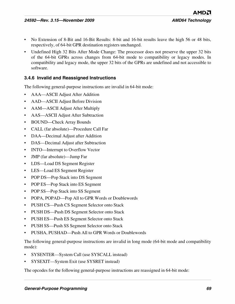
General-Purpose Programming 69
24592—Rev. 3.15—November 2009 AMD64 Technology
• No Extension of 8-Bit and 16-Bit Results: 8-bit and 16-bit results leave the high 56 or 48 bits,respectively, of 64-bit GPR destination registers unchanged.
• Undefined High 32 Bits After Mode Change: The processor does not preserve the upper 32 bitsof the 64-bit GPRs across changes from 64-bit mode to compatibility or legacy modes. Incompatibility and legacy mode, the upper 32 bits of the GPRs are undefined and not accessible tosoftware.
3.4.6 Invalid and Reassigned Instructions
The following general-purpose instructions are invalid in 64-bit mode:
• AAA—ASCII Adjust After Addition
• AAD—ASCII Adjust Before Division
• AAM—ASCII Adjust After Multiply
• AAS—ASCII Adjust After Subtraction
• BOUND—Check Array Bounds
• CALL (far absolute)—Procedure Call Far
• DAA—Decimal Adjust after Addition
• DAS—Decimal Adjust after Subtraction
• INTO—Interrupt to Overflow Vector
• JMP (far absolute)—Jump Far
• LDS—Load DS Segment Register
• LES—Load ES Segment Register
• POP DS—Pop Stack into DS Segment
• POP ES—Pop Stack into ES Segment
• POP SS—Pop Stack into SS Segment
• POPA, POPAD—Pop All to GPR Words or Doublewords
• PUSH CS—Push CS Segment Selector onto Stack
• PUSH DS—Push DS Segment Selector onto Stack
• PUSH ES—Push ES Segment Selector onto Stack
• PUSH SS—Push SS Segment Selector onto Stack
• PUSHA, PUSHAD—Push All to GPR Words or Doublewords
The following general-purpose instructions are invalid in long mode (64-bit mode and compatibilitymode):
• SYSENTER—System Call (use SYSCALL instead)
• SYSEXIT—System Exit (use SYSRET instead)
The opcodes for the following general-purpose instructions are reassigned in 64-bit mode:
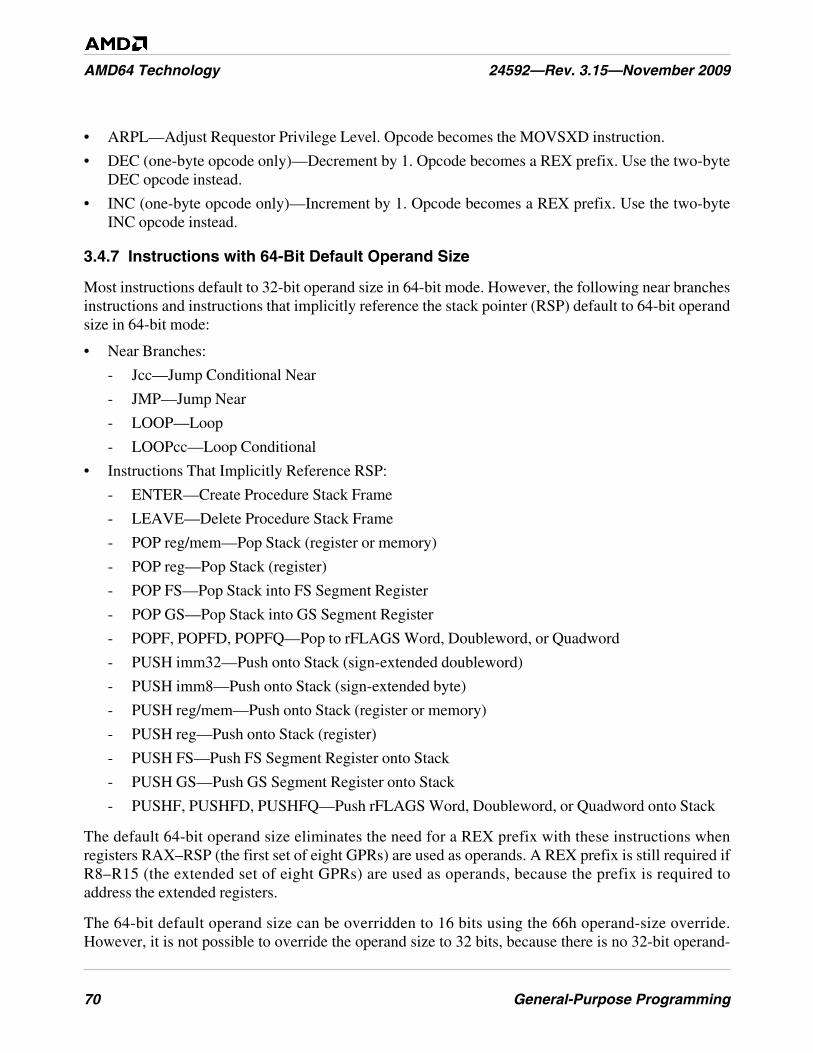
70 General-Purpose Programming
AMD64 Technology 24592—Rev. 3.15—November 2009
• ARPL—Adjust Requestor Privilege Level. Opcode becomes the MOVSXD instruction.
• DEC (one-byte opcode only)—Decrement by 1. Opcode becomes a REX prefix. Use the two-byteDEC opcode instead.
• INC (one-byte opcode only)—Increment by 1. Opcode becomes a REX prefix. Use the two-byteINC opcode instead.
3.4.7 Instructions with 64-Bit Default Operand Size
Most instructions default to 32-bit operand size in 64-bit mode. However, the following near branchesinstructions and instructions that implicitly reference the stack pointer (RSP) default to 64-bit operandsize in 64-bit mode:
• Near Branches:
- Jcc—Jump Conditional Near
- JMP—Jump Near
- LOOP—Loop
- LOOPcc—Loop Conditional
• Instructions That Implicitly Reference RSP:
- ENTER—Create Procedure Stack Frame
- LEAVE—Delete Procedure Stack Frame
- POP reg/mem—Pop Stack (register or memory)
- POP reg—Pop Stack (register)
- POP FS—Pop Stack into FS Segment Register
- POP GS—Pop Stack into GS Segment Register
- POPF, POPFD, POPFQ—Pop to rFLAGS Word, Doubleword, or Quadword
- PUSH imm32—Push onto Stack (sign-extended doubleword)
- PUSH imm8—Push onto Stack (sign-extended byte)
- PUSH reg/mem—Push onto Stack (register or memory)
- PUSH reg—Push onto Stack (register)
- PUSH FS—Push FS Segment Register onto Stack
- PUSH GS—Push GS Segment Register onto Stack
- PUSHF, PUSHFD, PUSHFQ—Push rFLAGS Word, Doubleword, or Quadword onto Stack
The default 64-bit operand size eliminates the need for a REX prefix with these instructions whenregisters RAX–RSP (the first set of eight GPRs) are used as operands. A REX prefix is still required ifR8–R15 (the extended set of eight GPRs) are used as operands, because the prefix is required toaddress the extended registers.
The 64-bit default operand size can be overridden to 16 bits using the 66h operand-size override.However, it is not possible to override the operand size to 32 bits, because there is no 32-bit operand-
General-Purpose Programming 71
24592—Rev. 3.15—November 2009 AMD64 Technology
size override prefix for 64-bit mode. For details on the operand-size prefix, see “Instruction Prefixes”in Volume 3.
For details on near branches, see “Near Branches in 64-Bit Mode” on page 85. For details oninstructions that implicitly reference RSP, see “Stack Operand-Size in 64-Bit Mode” on page 77.
For details on opcodes and operand-size overrides, see “General-Purpose Instructions in 64-Bit Mode”in Volume 3.
3.5 Instruction Prefixes
An instruction prefix is a byte that precedes an instruction’s opcode and modifies the instruction’soperation or operands. Instruction prefixes are of two types:
• Legacy Prefixes
• REX Prefixes
Legacy prefixes are organized into five groups, in which each prefix has a unique value. REX prefixes,which enable use of the AMD64 register extensions in 64-bit mode, are organized as a single group inwhich the value of the prefix indicates the combination of register-extension features to be enabled.
3.5.1 Legacy Prefixes
Table 3-7 on page 72 shows the legacy prefixes. These are organized into five groups, as shown in theleft-most column of the table. Each prefix has a unique hexadecimal value. The legacy prefixes canappear in any order in the instruction, but only one prefix from each of the five groups can be used in asingle instruction. The result of using multiple prefixes from a single group is undefined.
There are several restrictions on the use of prefixes. For example, the address-size prefix changesaddress size only for a memory operand, and only a single memory operand can be overridden in aninstruction. In general, the operand-size prefix cannot be used with x87 floating-point instructions, andwhen used with 128-bit or 64-bit media instructions that prefix acts in a special way to modify theopcode. The repeat prefixes cause repetition only with certain string instructions, and when used with128-bit or 64-bit media instructions the prefixes act in a special way to modify the opcode. The lockprefix can be used with only a small number of general-purpose instructions.
Table 3-7 on page 72 summarizes the functionality of instruction prefixes. Details about the prefixesand their restrictions are given in “Instruction Prefixes” in Volume 3.
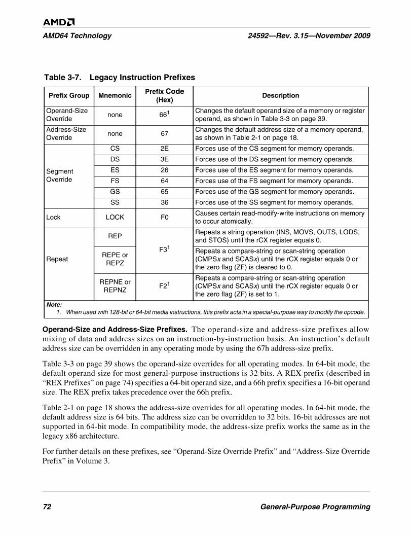
72 General-Purpose Programming
AMD64 Technology 24592—Rev. 3.15—November 2009
Operand-Size and Address-Size Prefixes. The operand-size and address-size prefixes allowmixing of data and address sizes on an instruction-by-instruction basis. An instruction’s defaultaddress size can be overridden in any operating mode by using the 67h address-size prefix.
Table 3-3 on page 39 shows the operand-size overrides for all operating modes. In 64-bit mode, thedefault operand size for most general-purpose instructions is 32 bits. A REX prefix (described in“REX Prefixes” on page 74) specifies a 64-bit operand size, and a 66h prefix specifies a 16-bit operandsize. The REX prefix takes precedence over the 66h prefix.
Table 2-1 on page 18 shows the address-size overrides for all operating modes. In 64-bit mode, thedefault address size is 64 bits. The address size can be overridden to 32 bits. 16-bit addresses are notsupported in 64-bit mode. In compatibility mode, the address-size prefix works the same as in thelegacy x86 architecture.
For further details on these prefixes, see “Operand-Size Override Prefix” and “Address-Size OverridePrefix” in Volume 3.
Table 3-7. Legacy Instruction Prefixes
Prefix Group Mnemonic Prefix Code(Hex)
Description
Operand-SizeOverride
none 661 Changes the default operand size of a memory or registeroperand, as shown in Table 3-3 on page 39.
Address-SizeOverride
none 67Changes the default address size of a memory operand,as shown in Table 2-1 on page 18.
SegmentOverride
CS 2E Forces use of the CS segment for memory operands.
DS 3E Forces use of the DS segment for memory operands.
ES 26 Forces use of the ES segment for memory operands.
FS 64 Forces use of the FS segment for memory operands.
GS 65 Forces use of the GS segment for memory operands.
SS 36 Forces use of the SS segment for memory operands.
Lock LOCK F0Causes certain read-modify-write instructions on memoryto occur atomically.
Repeat
REP
F31
Repeats a string operation (INS, MOVS, OUTS, LODS,and STOS) until the rCX register equals 0.
REPE orREPZ
Repeats a compare-string or scan-string operation(CMPSx and SCASx) until the rCX register equals 0 orthe zero flag (ZF) is cleared to 0.
REPNE orREPNZ
F21Repeats a compare-string or scan-string operation(CMPSx and SCASx) until the rCX register equals 0 orthe zero flag (ZF) is set to 1.
Note:1. When used with 128-bit or 64-bit media instructions, this prefix acts in a special-purpose way to modify the opcode.

General-Purpose Programming 73
24592—Rev. 3.15—November 2009 AMD64 Technology
Segment Override Prefix. The DS segment is the default segment for most memory operands. Manyinstructions allow this default data segment to be overridden using one of the six segment-overrideprefixes shown in Table 3-7 on page 72. Data-segment overrides will be ignored when accessing datain the following cases:
• When a stack reference is made that pushes data onto or pops data off of the stack. In those cases,the SS segment is always used.
• When the destination of a string is memory it is always referenced using the ES segment.
Instruction fetches from the CS segment cannot be overridden. However, the CS segment-overrideprefix can be used to access instructions as data objects and to access data stored in the code segment.
For further details on these prefixes, see “Segment-Override Prefixes” in Volume 3.
Lock Prefix. The LOCK prefix causes certain read-modify-write instructions that access memory tooccur atomically. The mechanism for doing so is implementation-dependent (for example, themechanism may involve locking of data-cache lines that contain copies of the referenced memoryoperands, and/or bus signaling or packet-messaging on the bus). The prefix is intended to give theprocessor exclusive use of shared memory operands in a multiprocessor system.
The prefix can only be used with forms of the following instructions that write a memory operand:ADC, ADD, AND, BTC, BTR, BTS, CMPXCHG, CMPXCHG8B, DEC, INC, NEG, NOT, OR, SBB,SUB, XADD, XCHG, and XOR. An invalid-opcode exception occurs if LOCK is used with any otherinstruction.
For further details on these prefixes, see “Lock Prefix” in Volume 3.
Repeat Prefixes. There are two repeat prefixes byte codes, F3h and F2h. Byte code F3h is the moregeneral and is usually treated as two distinct instructions by assemblers. Byte code F2h is only usedwith CMPSx and SCASx instructions:
• REP (F3h)—This more generalized repeat prefix repeats its associated string instruction thenumber of times specified in the counter register (rCX). Repetition stops when the value in rCXreaches 0. This prefix is used with the INS, LODS, MOVS, OUTS, and STOS instructions.
• REPE or REPZ (F3h)—This version of REP prefix repeats its associated string instruction thenumber of times specified in the counter register (rCX). Repetition stops when the value in rCXreaches 0 or when the zero flag (ZF) is cleared to 0. The prefix can only be used with the CMPSxand SCASx instructions.
• REPNE or REPNZ (F2h)—The REPNE or REPNZ prefix repeats its associated string instructionthe number of times specified in the counter register (rCX). Repetition stops when the value in rCXreaches 0 or when the zero flag (ZF) is set to 1. The prefix can only be used with the CMPSx andSCASx instructions.
The size of the rCX counter is determined by the effective address size. For further details about theseprefixes, including optimization of their use, see “Repeat Prefixes” in Volume 3.
74 General-Purpose Programming
AMD64 Technology 24592—Rev. 3.15—November 2009
3.5.2 REX Prefixes
REX prefixes are a new group of instruction-prefix bytes that can be used only in 64-bit mode. Theyenable the 64-bit register extensions. REX prefixes specify the following features:
• Use of an extended GPR register, shown in Figure 3-3 on page 27.
• Use of an extended XMM register, shown in Figure 4-12 on page 117.
• Use of a 64-bit (quadword) operand size, as described in “Operands” on page 36.
• Use of extended control and debug registers, as described in Volume 2.
REX prefix bytes have a value in the range 40h to 4Fh, depending on the particular combination ofregister extensions desired. With few exceptions, a REX prefix is required to access a 64-bit GPR orone of the extended GPR or XMM registers. A few instructions (described in “General-PurposeInstructions in 64-Bit Mode” in Volume 3) default to 64-bit operand size and do not need the REXprefix to access an extended 64-bit GPR.
An instruction can have only one REX prefix, and one such prefix is all that is needed to express thefull selection of 64-bit-mode register-extension features. The prefix, if used, must immediatelyprecede the first opcode byte of an instruction. Any other placement of a REX prefix is ignored. Thelegacy instruction-size limit of 15 bytes still applies to instructions that contain a REX prefix.
For further details on the REX prefixes, see “REX Prefixes” in Volume 3.
3.6 Feature Detection
The CPUID instruction provides information about the processor implementation and its capabilities.Software operating at any privilege level can execute the CPUID instruction to collect this information.After the information is collected, software can select procedures that optimize performance for aparticular hardware implementation. For example, application software can determine whether theAMD64 architecture’s long mode is supported by the processor, and it can determine the processorimplementation’s performance capabilities.
Support for the CPUID instruction is implementation-dependent, as determined by software’s abilityto write the RFLAGS.ID bit. The following code sample shows how to test for the presence of theCPUID instruction.
pushfd ; save EFLAGSpop eax ; store EFLAGS in EAXmov ebx, eax ; save in EBX for later testingxor eax, 00200000h ; toggle bit 21push eax ; push to stackpopfd ; save changed EAX to EFLAGSpushfd ; push EFLAGS to TOSpop eax ; store EFLAGS in EAXcmp eax, ebx ; see if bit 21 has changedjz NO_CPUID ; if no change, no CPUID
General-Purpose Programming 75
24592—Rev. 3.15—November 2009 AMD64 Technology
After software has determined that the processor implementation supports the CPUID instruction,software can test for support of specific features by loading a function code (value) into the EAXregister and executing the CPUID instruction. Processor feature information is returned in the EAX,EBX, ECX, and EDX registers, as described fully in “CPUID” in Volume 3.
The architecture supports CPUID information about standard functions and extended functions. Ingeneral, standard functions include the earliest features offered in the x86 architecture. Extendedfunctions include newer features of the x86 and AMD64 architectures, such as SSE, SSE2, SSE3, and3DNow! instructions, and long mode.
Standard functions are accessed by loading EAX with the value 0 (standard-function 0) or 1 (standard-function 1) and executing the CPUID instruction. All software using the CPUID instruction mustexecute standard-function 0, which identifies the processor vendor and the largest standard-functioninput value supported by the processor implementation. The CPUID standard-function 1 returns theprocessor version and standard-feature bits.
Software can test for support of extended functions by first executing the CPUID instruction with thevalue 8000_0000h in EAX. The processor returns, in EAX, the largest extended-function input valuedefined for the CPUID instruction on the processor implementation. If the value in EAX is greater than8000_0000h, extended functions are supported, although specific extended functions must be testedindividually.
The following code sample shows how to test for support of any extended functions:
mov eax, 80000000h ; query for extended functionsCPUID ; get extended function limitcmp eax, 80000000h ; is EAX greater than 80000000?jbe NO_EXTENDEDMSR ; no extended-feature support
If extended functions are supported, software can test for support of specific extended features. Forexample, software can determine whether the processor implementation supports long mode byexecuting the CPUID instruction with 8000_0001h in the EAX register, then testing to see if bit 29 inthe EDX register is set to 1. The following code sample shows how to test for long-mode support.
mov eax, 80000001h ; query for function 8000_0001hCPUID ; get feature bits in EDXtest edx, 20000000h ; test bit 29 in EDXjnz YES_Long_Mode ; long mode is supported
With a few exceptions, general-purpose instructions are supported in all hardware implementations ofthe AMD64 architecture, Exceptional instructions are implemented only if their associated CPUIDfunction bit is set. The implementation of certain media instructions (such as FXSAVE andFXRSTOR) and system instructions (such as RDMSR and WRMSR) is also indicated by CPUIDfunction bits. See “CPUID” in the AMD64 Architecture Programmer’s Manual Volume 3: GeneralPurpose and System Instructions, order# 24594, and the CPUID Specification, order# 25481, for a fulldescription of the CPUID instruction, all CPUID standard and extended functions, and the properinterpretation of returned values.
76 General-Purpose Programming
AMD64 Technology 24592—Rev. 3.15—November 2009
3.6.1 Feature Detection in a Virtualized Environment
Software writers must assume that their software may be executed as a guest in a virtualizedenvironment. A virtualized guest may be migrated between processors of differing capabilities, so theCPUID indication of a feature's presence must be respected. Operating systems, user programs andlibraries must all ensure that the CPUID instruction indicates a feature is present before using thatfeature. The hypervisor is responsible for ensuring consistent CPUID values across the system.
For example, an OS, program, or library typically detects a feature during initialization and thenconfigures code paths or internal copies of feature indications based on the detection of that feature,with the feature detection occurring once per initialization. In this case, the feature must be detected byuse of the CPUID instruction rather than by ignoring CPUID and testing for the presence of thatfeature.
To ensure guest migration between processors across multiple generations of processors, whileallowing for features to be deprecated in future generations of processors, it is imperative that softwarecheck the CPUID bit once per program or library initialization before using instructions that areindicated by a CPUID bit; otherwise inconsistent behavior may result.
3.7 Control Transfers
3.7.1 Overview
From the application-program’s viewpoint, program-control flow is sequential—that is, instructionsare addressed and executed sequentially—except when a branch instruction (a call, return, jump,interrupt, or return from interrupt) is encountered, in which case program flow changes to the branchinstruction’s target address. Branches are used to iterate through loops and move through conditionalprogram logic. Branches cause a new instruction pointer to be loaded into the rIP register, andsometimes cause the CS register to point to a different code segment. The CS:rIP values can bespecified as part of a branch instruction, or they can be read from a register or memory.
Branches can also be used to transfer control to another program or procedure running at a differentprivilege level. In such cases, the processor automatically checks the source program and targetprogram privileges to ensure that the transfer is allowed before loading CS:rIP with the new values.
3.7.2 Privilege Levels
The processor’s protected modes include legacy protected mode and long mode (both compatibilitymode and 64-bit mode). In all protected modes and virtual x86 mode, privilege levels are used toisolate and protect programs and data from each other. The privilege levels are designated with anumerical value from 0 to 3, with 0 being the most privileged and 3 being the least privileged. Privilege0 is normally reserved for critical system-software components that require direct access to, andcontrol over, all processor and system resources. Privilege 3 is used by application software. Theintermediate privilege levels (1 and 2) are used, for example, by device drivers and library routines thataccess and control a limited set of processor and system resources.
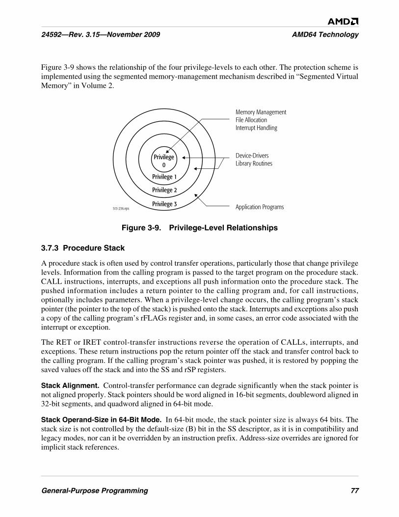
General-Purpose Programming 77
24592—Rev. 3.15—November 2009 AMD64 Technology
Figure 3-9 shows the relationship of the four privilege-levels to each other. The protection scheme isimplemented using the segmented memory-management mechanism described in “Segmented VirtualMemory” in Volume 2.
Figure 3-9. Privilege-Level Relationships
3.7.3 Procedure Stack
A procedure stack is often used by control transfer operations, particularly those that change privilegelevels. Information from the calling program is passed to the target program on the procedure stack.CALL instructions, interrupts, and exceptions all push information onto the procedure stack. Thepushed information includes a return pointer to the calling program and, for call instructions,optionally includes parameters. When a privilege-level change occurs, the calling program’s stackpointer (the pointer to the top of the stack) is pushed onto the stack. Interrupts and exceptions also pusha copy of the calling program’s rFLAGs register and, in some cases, an error code associated with theinterrupt or exception.
The RET or IRET control-transfer instructions reverse the operation of CALLs, interrupts, andexceptions. These return instructions pop the return pointer off the stack and transfer control back tothe calling program. If the calling program’s stack pointer was pushed, it is restored by popping thesaved values off the stack and into the SS and rSP registers.
Stack Alignment. Control-transfer performance can degrade significantly when the stack pointer isnot aligned properly. Stack pointers should be word aligned in 16-bit segments, doubleword aligned in32-bit segments, and quadword aligned in 64-bit mode.
Stack Operand-Size in 64-Bit Mode. In 64-bit mode, the stack pointer size is always 64 bits. Thestack size is not controlled by the default-size (B) bit in the SS descriptor, as it is in compatibility andlegacy modes, nor can it be overridden by an instruction prefix. Address-size overrides are ignored forimplicit stack references.
513-236.eps Application Programs
Memory ManagementFile AllocationInterrupt Handling
Device-DriversLibrary Routines
Privilege0
Privilege 1
Privilege 2
Privilege 3

78 General-Purpose Programming
AMD64 Technology 24592—Rev. 3.15—November 2009
Except for far branches, all instructions that implicitly reference the stack pointer default to 64-bitoperand size in 64-bit mode. Table 3-8 on page 79 lists these instructions.
The default 64-bit operand size eliminates the need for a REX prefix with these instructions. However,a REX prefix is still required if R8–R15 (the extended set of eight GPRs) are used as operands,because the prefix is required to address the extended registers. Pushes and pops of 32-bit stack valuesare not possible in 64-bit mode with these instructions, because there is no 32-bit operand-sizeoverride prefix for 64-bit mode.
3.7.4 Jumps
Jump instructions provide a simple means for transferring program control from one location toanother. Jumps do not affect the procedure stack, and return instructions cannot transfer control back tothe instruction following a jump. Two general types of jump instruction are available: unconditional(JMP) and conditional (Jcc).
There are two types of unconditional jumps (JMP):
• Near Jumps—When the target address is within the current code segment.
• Far Jumps—When the target address is outside the current code segment.
Although unconditional jumps can be used to change code segments, they cannot be used to changeprivilege levels.
Conditional jumps (Jcc) test the state of various bits in the rFLAGS register (or rCX) and jump to atarget location based on the results of that test. Only near forms of conditional jumps are available, soJcc cannot be used to transfer control to another code segment.
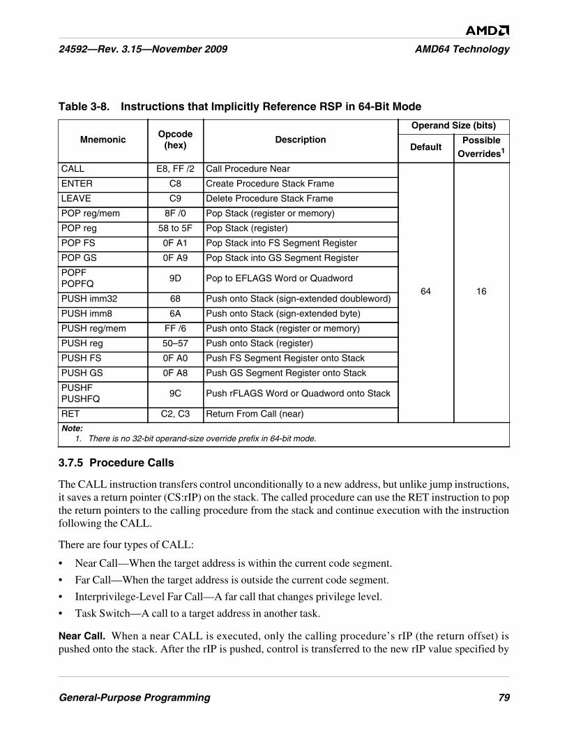
General-Purpose Programming 79
24592—Rev. 3.15—November 2009 AMD64 Technology
3.7.5 Procedure Calls
The CALL instruction transfers control unconditionally to a new address, but unlike jump instructions,it saves a return pointer (CS:rIP) on the stack. The called procedure can use the RET instruction to popthe return pointers to the calling procedure from the stack and continue execution with the instructionfollowing the CALL.
There are four types of CALL:
• Near Call—When the target address is within the current code segment.
• Far Call—When the target address is outside the current code segment.
• Interprivilege-Level Far Call—A far call that changes privilege level.
• Task Switch—A call to a target address in another task.
Near Call. When a near CALL is executed, only the calling procedure’s rIP (the return offset) ispushed onto the stack. After the rIP is pushed, control is transferred to the new rIP value specified by
Table 3-8. Instructions that Implicitly Reference RSP in 64-Bit Mode
MnemonicOpcode
(hex)Description
Operand Size (bits)
DefaultPossible
Overrides1
CALL E8, FF /2 Call Procedure Near
64 16
ENTER C8 Create Procedure Stack Frame
LEAVE C9 Delete Procedure Stack Frame
POP reg/mem 8F /0 Pop Stack (register or memory)
POP reg 58 to 5F Pop Stack (register)
POP FS 0F A1 Pop Stack into FS Segment Register
POP GS 0F A9 Pop Stack into GS Segment Register
POPFPOPFQ
9D Pop to EFLAGS Word or Quadword
PUSH imm32 68 Push onto Stack (sign-extended doubleword)
PUSH imm8 6A Push onto Stack (sign-extended byte)
PUSH reg/mem FF /6 Push onto Stack (register or memory)
PUSH reg 50–57 Push onto Stack (register)
PUSH FS 0F A0 Push FS Segment Register onto Stack
PUSH GS 0F A8 Push GS Segment Register onto Stack
PUSHFPUSHFQ
9C Push rFLAGS Word or Quadword onto Stack
RET C2, C3 Return From Call (near)
Note:1. There is no 32-bit operand-size override prefix in 64-bit mode.
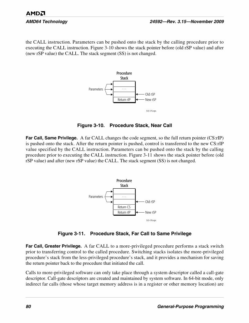
80 General-Purpose Programming
AMD64 Technology 24592—Rev. 3.15—November 2009
the CALL instruction. Parameters can be pushed onto the stack by the calling procedure prior toexecuting the CALL instruction. Figure 3-10 shows the stack pointer before (old rSP value) and after(new rSP value) the CALL. The stack segment (SS) is not changed.
Figure 3-10. Procedure Stack, Near Call
Far Call, Same Privilege. A far CALL changes the code segment, so the full return pointer (CS:rIP)is pushed onto the stack. After the return pointer is pushed, control is transferred to the new CS:rIPvalue specified by the CALL instruction. Parameters can be pushed onto the stack by the callingprocedure prior to executing the CALL instruction. Figure 3-11 shows the stack pointer before (oldrSP value) and after (new rSP value) the CALL. The stack segment (SS) is not changed.
Figure 3-11. Procedure Stack, Far Call to Same Privilege
Far Call, Greater Privilege. A far CALL to a more-privileged procedure performs a stack switchprior to transferring control to the called procedure. Switching stacks isolates the more-privilegedprocedure’s stack from the less-privileged procedure’s stack, and it provides a mechanism for savingthe return pointer back to the procedure that initiated the call.
Calls to more-privileged software can only take place through a system descriptor called a call-gatedescriptor. Call-gate descriptors are created and maintained by system software. In 64-bit mode, onlyindirect far calls (those whose target memory address is in a register or other memory location) are
513-175.eps
ProcedureStack
New rSPReturn rIPOld rSP
Parameters . . .
513-176.eps
ProcedureStack
Return CSOld rSP
New rSP
Parameters
Return rIP
. . .
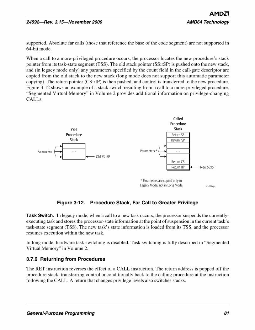
General-Purpose Programming 81
24592—Rev. 3.15—November 2009 AMD64 Technology
supported. Absolute far calls (those that reference the base of the code segment) are not supported in64-bit mode.
When a call to a more-privileged procedure occurs, the processor locates the new procedure’s stackpointer from its task-state segment (TSS). The old stack pointer (SS:rSP) is pushed onto the new stack,and (in legacy mode only) any parameters specified by the count field in the call-gate descriptor arecopied from the old stack to the new stack (long mode does not support this automatic parametercopying). The return pointer (CS:rIP) is then pushed, and control is transferred to the new procedure.Figure 3-12 shows an example of a stack switch resulting from a call to a more-privileged procedure.“Segmented Virtual Memory” in Volume 2 provides additional information on privilege-changingCALLs.
Figure 3-12. Procedure Stack, Far Call to Greater Privilege
Task Switch. In legacy mode, when a call to a new task occurs, the processor suspends the currently-executing task and stores the processor-state information at the point of suspension in the current task’stask-state segment (TSS). The new task’s state information is loaded from its TSS, and the processorresumes execution within the new task.
In long mode, hardware task switching is disabled. Task switching is fully described in “SegmentedVirtual Memory” in Volume 2.
3.7.6 Returning from Procedures
The RET instruction reverses the effect of a CALL instruction. The return address is popped off theprocedure stack, transferring control unconditionally back to the calling procedure at the instructionfollowing the CALL. A return that changes privilege levels also switches stacks.
513-177.eps
OldProcedure
Stack
Old SS:rSPParameters . . .
CalledProcedure
Stack
New SS:rSP
Parameters *
* Parameters are copied only in Legacy Mode, not in Long Mode.
Return CSReturn rIP
. . .
Return SSReturn rSP
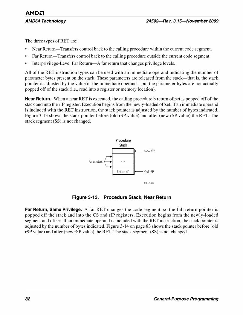
82 General-Purpose Programming
AMD64 Technology 24592—Rev. 3.15—November 2009
The three types of RET are:
• Near Return—Transfers control back to the calling procedure within the current code segment.
• Far Return—Transfers control back to the calling procedure outside the current code segment.
• Interprivilege-Level Far Return—A far return that changes privilege levels.
All of the RET instruction types can be used with an immediate operand indicating the number ofparameter bytes present on the stack. These parameters are released from the stack—that is, the stackpointer is adjusted by the value of the immediate operand—but the parameter bytes are not actuallypopped off of the stack (i.e., read into a register or memory location).
Near Return. When a near RET is executed, the calling procedure’s return offset is popped off of thestack and into the rIP register. Execution begins from the newly-loaded offset. If an immediate operandis included with the RET instruction, the stack pointer is adjusted by the number of bytes indicated.Figure 3-13 shows the stack pointer before (old rSP value) and after (new rSP value) the RET. Thestack segment (SS) is not changed.
Figure 3-13. Procedure Stack, Near Return
Far Return, Same Privilege. A far RET changes the code segment, so the full return pointer ispopped off the stack and into the CS and rIP registers. Execution begins from the newly-loadedsegment and offset. If an immediate operand is included with the RET instruction, the stack pointer isadjusted by the number of bytes indicated. Figure 3-14 on page 83 shows the stack pointer before (oldrSP value) and after (new rSP value) the RET. The stack segment (SS) is not changed.
513-178.eps
ProcedureStack
Old rSPReturn rIP
New rSP
Parameters . . .
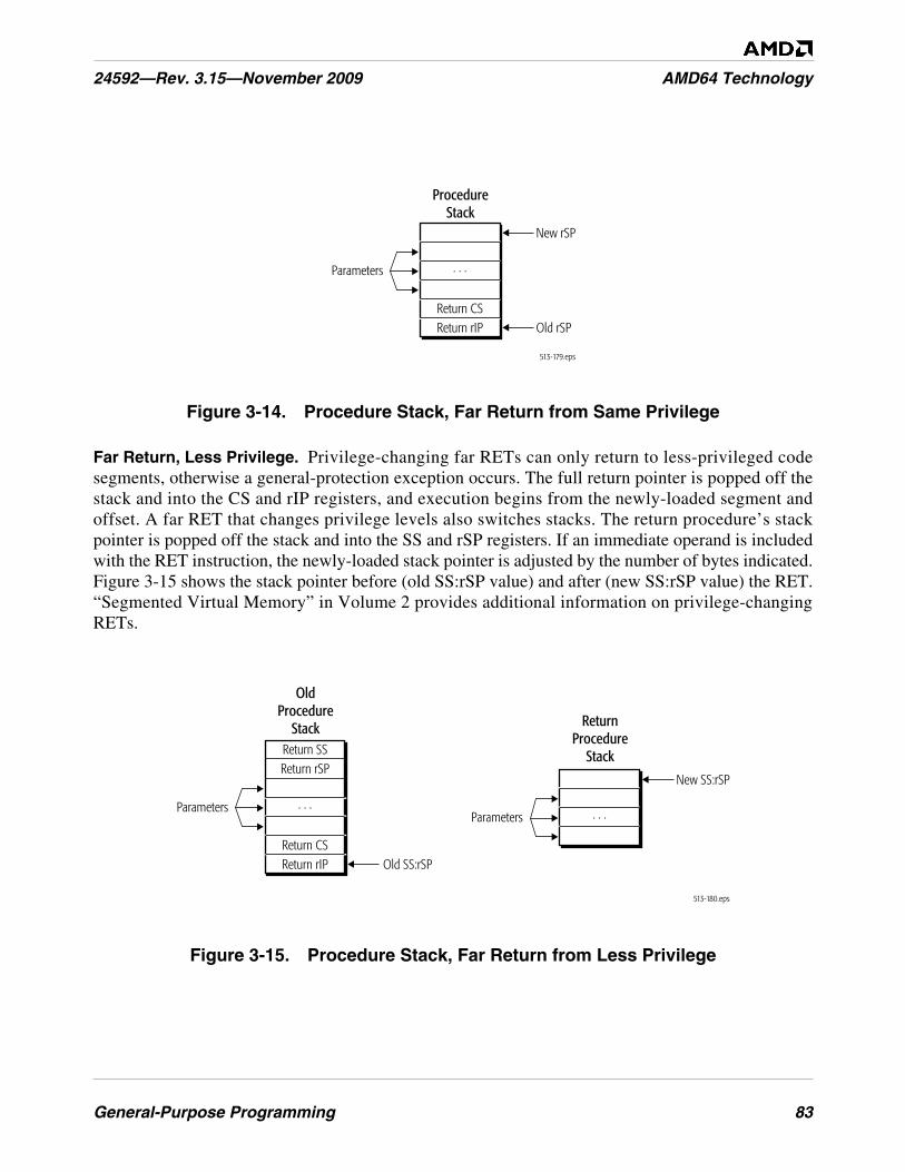
General-Purpose Programming 83
24592—Rev. 3.15—November 2009 AMD64 Technology
Figure 3-14. Procedure Stack, Far Return from Same Privilege
Far Return, Less Privilege. Privilege-changing far RETs can only return to less-privileged codesegments, otherwise a general-protection exception occurs. The full return pointer is popped off thestack and into the CS and rIP registers, and execution begins from the newly-loaded segment andoffset. A far RET that changes privilege levels also switches stacks. The return procedure’s stackpointer is popped off the stack and into the SS and rSP registers. If an immediate operand is includedwith the RET instruction, the newly-loaded stack pointer is adjusted by the number of bytes indicated.Figure 3-15 shows the stack pointer before (old SS:rSP value) and after (new SS:rSP value) the RET.“Segmented Virtual Memory” in Volume 2 provides additional information on privilege-changingRETs.
Figure 3-15. Procedure Stack, Far Return from Less Privilege
513-179.eps
ProcedureStack
Return CS
New rSP
Old rSP
Parameters
Return rIP
. . .
513-180.eps
ReturnProcedure
Stack
New SS:rSP
Parameters . . .
OldProcedure
Stack
Old SS:rSP
Parameters
Return CSReturn rIP
. . .
Return SSReturn rSP
84 General-Purpose Programming
AMD64 Technology 24592—Rev. 3.15—November 2009
3.7.7 System Calls
A disadvantage of far CALLs and far RETs is that they use segment-based protection and privilege-checking. This involves significant overhead associated with loading new segment selectors and theircorresponding descriptors into the segment registers. The overhead includes not only the time requiredto load the descriptors from memory but also the time required to perform the privilege, type, and limitchecks. Privilege-changing CALLs to the operating system are slowed further by the control transferthrough a gate descriptor.
SYSCALL and SYSRET. SYSCALL and SYSRET are low-latency system-call and system-returncontrol-transfer instructions. They can be used in protected mode. These instructions eliminatesegment-based privilege checking by using pre-determined target and return code segments and stacksegments. The operating system sets up and maintains the predetermined segments using specialregisters within the processor, so the segment descriptors do not need to be fetched from memory whenthe instructions are used. The simplifications made to privilege checking allow SYSCALL andSYSRET to complete in far fewer processor clock cycles than CALL and RET.
SYSRET can only be used to return from CPL = 0 procedures and is not available to applicationsoftware. SYSCALL can be used by applications to call operating system service routines running atCPL = 0. The SYSCALL instruction does not take operands. Linkage conventions are initialized andmaintained by the operating system. “System-Management Instructions” in Volume 2 containsdetailed information on the operation of SYSCALL and SYSRET.
SYSENTER and SYSEXIT. The SYSENTER and SYSEXIT instructions provide similar capabilitiesto SYSCALL and SYSRET. However, these instructions can be used only in legacy mode and are notsupported in long mode. SYSCALL and SYSRET are the preferred instructions for calling privilegedsoftware. See “System-Management Instructions” in Volume 2 for further information on SYSENTERand SYSEXIT.
3.7.8 General Considerations for Branching
Branching causes delays which are a function of the hardware-implementation’s branch-predictioncapabilities. Sequential flow avoids the delays caused by branching but is still exposed to delayscaused by cache misses, memory bus bandwidth, and other factors.
In general, branching code should be replaced with sequential code whenever practical. This isespecially important if the branch body is small (resulting in frequent branching) and when branchesdepend on random data (resulting in frequent mispredictions of the branch target). In certain hardwareimplementations, far branches (as opposed to near branches) may not be predictable by the hardware,and recursive functions (those that call themselves) may overflow a return-address stack.
All calls and returns should be paired for optimal performance. Hardware implementations thatinclude a return-address stack can lose stack synchronization if calls and returns are not paired.
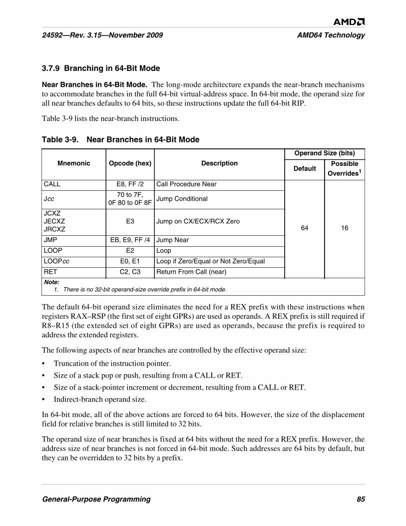
General-Purpose Programming 85
24592—Rev. 3.15—November 2009 AMD64 Technology
3.7.9 Branching in 64-Bit Mode
Near Branches in 64-Bit Mode. The long-mode architecture expands the near-branch mechanismsto accommodate branches in the full 64-bit virtual-address space. In 64-bit mode, the operand size forall near branches defaults to 64 bits, so these instructions update the full 64-bit RIP.
Table 3-9 lists the near-branch instructions.
The default 64-bit operand size eliminates the need for a REX prefix with these instructions whenregisters RAX–RSP (the first set of eight GPRs) are used as operands. A REX prefix is still required ifR8–R15 (the extended set of eight GPRs) are used as operands, because the prefix is required toaddress the extended registers.
The following aspects of near branches are controlled by the effective operand size:
• Truncation of the instruction pointer.
• Size of a stack pop or push, resulting from a CALL or RET.
• Size of a stack-pointer increment or decrement, resulting from a CALL or RET.
• Indirect-branch operand size.
In 64-bit mode, all of the above actions are forced to 64 bits. However, the size of the displacementfield for relative branches is still limited to 32 bits.
The operand size of near branches is fixed at 64 bits without the need for a REX prefix. However, theaddress size of near branches is not forced in 64-bit mode. Such addresses are 64 bits by default, butthey can be overridden to 32 bits by a prefix.
Table 3-9. Near Branches in 64-Bit Mode
Mnemonic Opcode (hex) Description
Operand Size (bits)
DefaultPossible
Overrides1
CALL E8, FF /2 Call Procedure Near
64 16
Jcc70 to 7F,
0F 80 to 0F 8FJump Conditional
JCXZJECXZJRCXZ
E3 Jump on CX/ECX/RCX Zero
JMP EB, E9, FF /4 Jump Near
LOOP E2 Loop
LOOPcc E0, E1 Loop if Zero/Equal or Not Zero/Equal
RET C2, C3 Return From Call (near)
Note:1. There is no 32-bit operand-size override prefix in 64-bit mode.
86 General-Purpose Programming
AMD64 Technology 24592—Rev. 3.15—November 2009
Branches to 64-Bit Offsets. Because immediates are generally limited to 32 bits, the only way a full64-bit absolute RIP can be specified in 64-bit mode is with an indirect branch. For this reason, directforms of far branches are invalid in 64-bit mode.
3.7.10 Interrupts and Exceptions
Interrupts and exceptions are a form of control transfer operation. They are used to call special system-service routines, called interrupt handlers, which are designed to respond to the interrupt or exceptioncondition. Pointers to the interrupt handlers are stored by the operating system in an interrupt-descriptor table, or IDT. In legacy real mode, the IDT contains an array of 4-byte far pointers tointerrupt handlers. In legacy protected mode, the IDT contains an array of 8-byte gate descriptors. Inlong mode, the gate descriptors are 16 bytes. Interrupt gates, task gates, and trap gates can be stored inthe IDT, but not call gates.
Interrupt handlers are usually privileged software because they typically require access to restrictedsystem resources. System software is responsible for creating the interrupt gates and storing them inthe IDT. “Exceptions and Interrupts” in Volume 2 contains detailed information on the interruptmechanism and the requirements on system software for managing the mechanism.
The IDT is indexed using the interrupt number, or vector. How the vector is specified depends on thesource, as described below. The first 32 of the available 256 interrupt vectors are reserved for internaluse by the processor—for exceptions (as described below) and other purposes.
Interrupts are caused either by software or hardware. The INT, INT3, and INTO instructionsimplement a software interrupt by calling an interrupt handler directly. These are general-purpose(privilege-level-3) instructions. The operand of the INT instruction is an immediate byte valuespecifying the interrupt vector used to index the IDT. INT3 and INTO are specific forms of softwareinterrupts used to call interrupt 3 and interrupt 4, respectively. External interrupts are produced bysystem logic which passes the IDT index to the processor via input signals. External interrupts can beeither maskable or non-maskable.
Exceptions usually occur as a result of software execution errors or other internal-processor errors.Exceptions can also occur in non-error situations, such as debug-program single-stepping or address-breakpoint detection. In the case of exceptions, the processor produces the IDT index based on thedetected condition. The handlers for interrupts and exceptions are identical for a given vector.
The processor’s response to an exception depends on the type of the exception. For all exceptionsexcept 128-bit-media and x87 floating-point exceptions, control automatically transfers to the handler(or service routine) for that exception, as defined by the exceptions vector. For 128-bit-media and x87floating-point exceptions, there is both a masked and unmasked response. When unmasked, theseexceptions invoke their exception handler. When masked, a default masked response is providedinstead of invoking the exception handler.
Exceptions and software-initiated interrupts occur synchronously with respect to the processor clock.There are three types of exceptions:
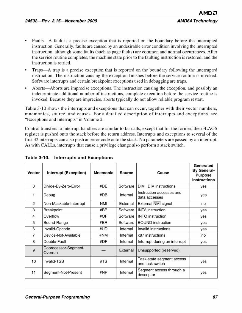
General-Purpose Programming 87
24592—Rev. 3.15—November 2009 AMD64 Technology
• Faults—A fault is a precise exception that is reported on the boundary before the interruptedinstruction. Generally, faults are caused by an undesirable error condition involving the interruptedinstruction, although some faults (such as page faults) are common and normal occurrences. Afterthe service routine completes, the machine state prior to the faulting instruction is restored, and theinstruction is retried.
• Traps—A trap is a precise exception that is reported on the boundary following the interruptedinstruction. The instruction causing the exception finishes before the service routine is invoked.Software interrupts and certain breakpoint exceptions used in debugging are traps.
• Aborts—Aborts are imprecise exceptions. The instruction causing the exception, and possibly anindeterminate additional number of instructions, complete execution before the service routine isinvoked. Because they are imprecise, aborts typically do not allow reliable program restart.
Table 3-10 shows the interrupts and exceptions that can occur, together with their vector numbers,mnemonics, source, and causes. For a detailed description of interrupts and exceptions, see“Exceptions and Interrupts” in Volume 2.
Control transfers to interrupt handlers are similar to far calls, except that for the former, the rFLAGSregister is pushed onto the stack before the return address. Interrupts and exceptions to several of thefirst 32 interrupts can also push an error code onto the stack. No parameters are passed by an interrupt.As with CALLs, interrupts that cause a privilege change also perform a stack switch.
Table 3-10. Interrupts and Exceptions
Vector Interrupt (Exception) Mnemonic Source Cause
GeneratedBy General-
PurposeInstructions
0 Divide-By-Zero-Error #DE Software DIV, IDIV instructions yes
1 Debug #DB InternalInstruction accesses anddata accesses
yes
2 Non-Maskable-Interrupt NMI External External NMI signal no
3 Breakpoint #BP Software INT3 instruction yes
4 Overflow #OF Software INTO instruction yes
5 Bound-Range #BR Software BOUND instruction yes
6 Invalid-Opcode #UD Internal Invalid instructions yes
7 Device-Not-Available #NM Internal x87 instructions no
8 Double-Fault #DF Internal Interrupt during an interrupt yes
9Coprocessor-Segment-Overrun
— External Unsupported (reserved)
10 Invalid-TSS #TS InternalTask-state segment accessand task switch
yes
11 Segment-Not-Present #NP InternalSegment access through adescriptor
yes
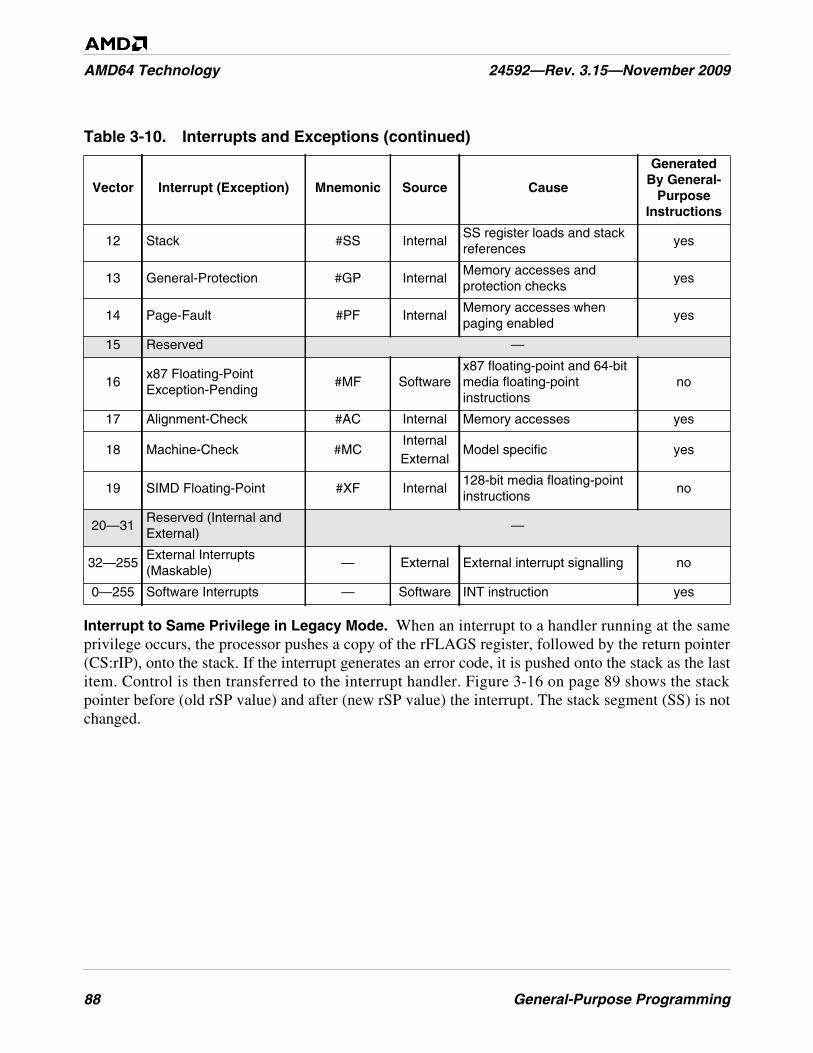
88 General-Purpose Programming
AMD64 Technology 24592—Rev. 3.15—November 2009
Interrupt to Same Privilege in Legacy Mode. When an interrupt to a handler running at the sameprivilege occurs, the processor pushes a copy of the rFLAGS register, followed by the return pointer(CS:rIP), onto the stack. If the interrupt generates an error code, it is pushed onto the stack as the lastitem. Control is then transferred to the interrupt handler. Figure 3-16 on page 89 shows the stackpointer before (old rSP value) and after (new rSP value) the interrupt. The stack segment (SS) is notchanged.
12 Stack #SS InternalSS register loads and stackreferences
yes
13 General-Protection #GP InternalMemory accesses andprotection checks
yes
14 Page-Fault #PF InternalMemory accesses whenpaging enabled
yes
15 Reserved —
16x87 Floating-PointException-Pending
#MF Softwarex87 floating-point and 64-bitmedia floating-pointinstructions
no
17 Alignment-Check #AC Internal Memory accesses yes
18 Machine-Check #MCInternalExternal
Model specific yes
19 SIMD Floating-Point #XF Internal128-bit media floating-pointinstructions
no
20—31Reserved (Internal andExternal)
—
32—255External Interrupts(Maskable)
— External External interrupt signalling no
0—255 Software Interrupts — Software INT instruction yes
Table 3-10. Interrupts and Exceptions (continued)
Vector Interrupt (Exception) Mnemonic Source Cause
GeneratedBy General-
PurposeInstructions
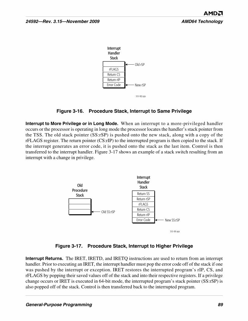
General-Purpose Programming 89
24592—Rev. 3.15—November 2009 AMD64 Technology
Figure 3-16. Procedure Stack, Interrupt to Same Privilege
Interrupt to More Privilege or in Long Mode. When an interrupt to a more-privileged handleroccurs or the processor is operating in long mode the processor locates the handler’s stack pointer fromthe TSS. The old stack pointer (SS:rSP) is pushed onto the new stack, along with a copy of therFLAGS register. The return pointer (CS:rIP) to the interrupted program is then copied to the stack. Ifthe interrupt generates an error code, it is pushed onto the stack as the last item. Control is thentransferred to the interrupt handler. Figure 3-17 shows an example of a stack switch resulting from aninterrupt with a change in privilege.
Figure 3-17. Procedure Stack, Interrupt to Higher Privilege
Interrupt Returns. The IRET, IRETD, and IRETQ instructions are used to return from an interrupthandler. Prior to executing an IRET, the interrupt handler must pop the error code off of the stack if onewas pushed by the interrupt or exception. IRET restores the interrupted program’s rIP, CS, andrFLAGS by popping their saved values off of the stack and into their respective registers. If a privilegechange occurs or IRET is executed in 64-bit mode, the interrupted program’s stack pointer (SS:rSP) isalso popped off of the stack. Control is then transferred back to the interrupted program.
513-182.eps
Old rSP
InterruptHandler
Stack
New rSP
Return CSReturn rIP
rFLAGS
Error Code
513-181.eps
OldProcedure
Stack
Old SS:rSP
InterruptHandler
Stack
New SS:rSP
Return CSReturn rIP
rFLAGS
Return SSReturn rSP
Error Code
90 General-Purpose Programming
AMD64 Technology 24592—Rev. 3.15—November 2009
3.8 Input/Output
I/O devices allow the processor to communicate with the outside world, usually to a human or toanother system. In fact, a system without I/O has little utility. Typical I/O devices include a keyboard,mouse, LAN connection, printer, storage devices, and monitor. The speeds these devices must operateat vary greatly, and usually depend on whether the communication is to a human (slow) or to anothermachine (fast). There are exceptions. For example, humans can consume graphics data at very highrates.
There are two methods for communicating with I/O devices in AMD64 processor implementations.One method involves accessing I/O through ports located in I/O-address space (“I/O Addressing” onpage 90), and the other method involves accessing I/O devices located in the memory-address space(“Memory Organization” on page 9). The address spaces are separate and independent of each other.
I/O-address space was originally introduced as an optimized means for accessing I/O-device controlports. Then, systems usually had few I/O devices, devices tended to be relatively low-speed, deviceaccesses needed to be strongly ordered to guarantee proper operation, and device protectionrequirements were minimal or non-existent. Memory-mapped I/O has largely supplanted I/O-addressspace access as the preferred means for modern operating systems to interface with I/O devices.Memory-mapped I/O offers greater flexibility in protection, vastly more I/O ports, higher speeds, andstrong or weak ordering to suit the device requirements.
3.8.1 I/O Addressing
Access to I/O-address space is provided by the IN and OUT instructions, and the string variants ofthese instructions, INS and OUTS. The operation of these instructions are described in “Input/Output”on page 63. Although not required, processor implementations generally transmit I/O-port addressesand I/O data over the same external signals used for memory addressing and memory data. Differentbus-cycles generated by the processor differentiate I/O-address space accesses from memory-addressspace accesses.
I/O-Address Space. Figure 3-18 on page 91 shows the 64 Kbyte I/O-address space. I/O ports can beaddressed as bytes, words, or doublewords. As with memory addressing, word-I/O and doubleword-I/O ports are simply two or four consecutively-addressed byte-I/O ports. Word and doubleword I/Oports can be aligned on any byte boundary, but there is typically a performance penalty for unalignedaccesses. Performance is optimized by aligning word-I/O ports on word boundaries, and doubleword-I/O ports on doubleword boundaries.
General-Purpose Programming 91
24592—Rev. 3.15—November 2009 AMD64 Technology
Figure 3-18. I/O Address Space
Memory-Mapped I/O. Memory-mapped I/O devices are attached to the system memory bus andrespond to memory transactions as if they were memory devices, such as DRAM. Access to memory-mapped I/O devices can be performed using any instruction that accesses memory, but typically MOVinstructions are used to transfer data between the processor and the device. Some I/O devices may haverestrictions on read-modify-write accesses.
Any location in memory can be used as a memory-mapped I/O address. System software can use thepaging facilities to virtualize memory devices and protect them from unauthorized access. See“System-Management Instructions” in Volume 2 for a discussion of memory virtualization andpaging.
3.8.2 I/O Ordering
The order of read and write accesses between the processor and an I/O device is usually important forproperly controlling device operation. Accesses to I/O-address space and memory-address space differin the default ordering enforced by the processor and the ability of software to control ordering.
I/O-Address Space. The processor always orders I/O-address space operations strongly, with respectto other I/O and memory operations. Software cannot modify the I/O ordering enforced by theprocessor. IN instructions are not executed until all previous writes to I/O space and memory havecompleted. OUT instructions delay execution of the following instruction until all writes—includingthe write performed by the OUT—have completed. Unlike memory writes, writes to I/O addresses arenever buffered by the processor.
The processor can use more than one bus transaction to access an unaligned, multi-byte I/O port.Unaligned accesses to I/O-address space do not have a defined bus transaction ordering, and thatordering can change from one implementation to another. If the use of an unaligned I/O port isrequired, and the order of bus transactions to that port is important, software should decompose theaccess into multiple, smaller aligned accesses.
Memory-Mapped I/O. To maximize software performance, processor implementations can executeinstructions out of program order. This can cause the sequence of memory accesses to also be out ofprogram order, called weakly ordered. As described in “Accessing Memory” on page 93, the processorcan perform memory reads in any order, it can perform reads without knowing whether it requires the
513-187.eps
0000
FFFF 216 - 1
0
92 General-Purpose Programming
AMD64 Technology 24592—Rev. 3.15—November 2009
result (speculation), and it can reorder reads ahead of writes. In the case of writes, multiple writes tomemory locations in close proximity to each other can be combined into a single write or a burst ofmultiple writes. Writes can also be delayed, or buffered, by the processor.
Application software that needs to force memory ordering to memory-mapped I/O devices can do sousing the read/write barrier instructions: LFENCE, SFENCE, and MFENCE. These instructions aredescribed in “Forcing Memory Order” on page 94. Serializing instructions, I/O instructions, andlocked instructions can also be used as read/write barriers, but they modify program state and are aninferior method for enforcing strong-memory ordering.
Typically, the operating system controls access to memory-mapped I/O devices. The AMD64architecture provides facilities for system software to specify the types of accesses and their orderingfor entire regions of memory. These facilities are also used to manage the cacheability of memoryregions. See “System-Management Instructions” in Volume 2 for further information.
3.8.3 Protected-Mode I/O
In protected mode, access to the I/O-address space is governed by the I/O privilege level (IOPL) fieldin the rFLAGS register, and the I/O-permission bitmap in the current task-state segment (TSS).
I/O-Privilege Level. RFLAGS.IOPL governs access to IOPL-sensitive instructions. All of the I/Oinstructions (IN, INS, OUT, and OUTS) are IOPL-sensitive. IOPL-sensitive instructions cannot beexecuted by a program unless the program’s current-privilege level (CPL) is numerically less (moreprivileged) than or equal to the RFLAGS.IOPL field, otherwise a general-protection exception (#GP)occurs.
Only software running at CPL = 0 can change the RFLAGS.IOPL field. Two instructions, POPF andIRET, can be used to change the field. If application software (or any software running at CPL>0)attempts to change RFLAGS.IOPL, the attempt is ignored.
System software uses RFLAGS.IOPL to control the privilege level required to access I/O-addressspace devices. Access can be granted on a program-by-program basis using different copies ofRFLAGS for every program, each with a different IOPL. RFLAGS.IOPL acts as a global control overa program’s access to I/O-address space devices. System software can grant less-privileged programsaccess to individual I/O devices (overriding RFLAGS.IOPL) by using the I/O-permission bitmapstored in a program’s TSS. For details about the I/O-permission bitmap, see “I/O-Permission Bitmap”in Volume 2.
3.9 Memory Optimization
Generally, application software is unaware of the memory hierarchy implemented within a particularsystem design. The application simply sees a homogenous address space within a single level ofmemory. In reality, both system and processor implementations can use any number of techniques tospeed up accesses into memory, doing so in a manner that is transparent to applications. Applicationsoftware can be written to maximize this speed-up even though the methods used by the hardware arenot visible to the application. This section gives an overview of the memory hierarchy and access
General-Purpose Programming 93
24592—Rev. 3.15—November 2009 AMD64 Technology
techniques that can be implemented within a system design, and how applications can optimize theiruse.
3.9.1 Accessing Memory
Implementations of the AMD64 architecture commit the results of each instruction—i.e., store theresult of the executed instruction in software-visible resources, such as a register (including flags), thedata cache, an internal write buffer, or memory—in program order, which is the order specified by theinstruction sequence in a program. Transparent to the application, implementations can executeinstructions in any order and temporarily hold out-of-order results until the instructions are committed.Implementations can also speculatively execute instructions—executing instructions before knowingtheir results will be used (for example, executing both sides of a branch). By executing instructionsout-of-order and speculatively, a processor can boost application performance by executinginstructions that are ready, rather than delaying them behind instructions that are waiting for data.However, the processor commits results in program order (the order expected by software).
When executing instructions out-of-order and speculatively, processor implementations often find ituseful to also allow out-of-order and speculative memory accesses. However, such memory accessesare potentially visible to software and system devices. The following sections describe thearchitectural rules for memory accesses. See “Memory System” in Volume 2 for information on howsystem software can further specify the flexibility of memory accesses.
Read Ordering. The ordering of memory reads does not usually affect program execution becausethe ordering does not usually affect the state of software-visible resources. The rules governing readordering are:
• Out-of-order reads are allowed. Out-of-order reads can occur as a result of out-of-order instructionexecution. The processor can read memory out-of-order to prevent stalling instructions that areexecuted out-of-order.
• Speculative reads are allowed. A speculative read occurs when the processor begins executing amemory-read instruction before it knows whether the instruction’s result will actually be needed.For example, the processor can predict a branch to occur and begin executing instructionsfollowing the predicted branch, before it knows whether the prediction is valid. When one of thespeculative instructions reads data from memory, the read itself is speculative.
• Reads can usually be reordered ahead of writes. Reads are generally given a higher priority by theprocessor than writes because instruction execution stalls if the read data required by an instructionis not immediately available. Allowing reads ahead of writes usually maximizes softwareperformance.
Reads can be reordered ahead of writes, except that a read cannot be reordered ahead of a priorwrite if the read is from the same location as the prior write. In this case, the read instruction stallsuntil the write instruction is committed. This is because the result of the write instruction isrequired by the read instruction for software to operate correctly.
94 General-Purpose Programming
AMD64 Technology 24592—Rev. 3.15—November 2009
Some system devices might be sensitive to reads. Normally, applications do not have direct access tosystem devices, but instead call an operating-system service routine to perform the access on theapplication’s behalf. In this case, it is system software’s responsibility to enforce strong read-ordering.
Write Ordering. Writes affect program order because they affect the state of software-visibleresources. The rules governing write ordering are restrictive:
• Generally, out-of-order writes are not allowed. Write instructions executed out-of-order cannotcommit (write) their result to memory until all previous instructions have completed in programorder. The processor can, however, hold the result of an out-of-order write instruction in a privatebuffer (not visible to software) until that result can be committed to memory.
System software can create non-cacheable write-combining regions in memory when the order ofwrites is known to not affect system devices. When writes are performed to write-combiningmemory, they can appear to complete out of order relative to other writes. See “Memory System”in Volume 2 for additional information.
• Speculative writes are not allowed. As with out-of-order writes, speculative write instructionscannot commit their result to memory until all previous instructions have completed in programorder. Processors can hold the result in a private buffer (not visible to software) until the result canbe committed.
Atomicity of accesses. Single load or store operations (from instructions that do just a single load orstore) are naturally atomic on any AMD64 processor as long as they do not cross an aligned 8-byteboundary. Accesses up to eight bytes in size which do cross such a boundary may be performedatomically using certain instructions with a lock prefix, such as XCHG, CMPXCHG orCMPXCHG8B, as long as all such accesses are done using the same technique. (Note that misalignedlocked accesses may be subject to heavy performance penalties.) CMPXCHG16B can be used toperform 16-byte atomic accesses in 64-bit mode (with certain alignment restrictions).
3.9.2 Forcing Memory Order
Special instructions are provided for application software to force memory ordering in situationswhere such ordering is important. These instructions are:
• Load Fence—The LFENCE instruction forces ordering of memory loads (reads). All memoryloads preceding the LFENCE (in program order) are completed prior to completing memory loadsfollowing the LFENCE. Memory loads cannot be reordered around an LFENCE instruction, butother non-serializing instructions (such as memory writes) can be reordered around the LFENCE.
• Store Fence—The SFENCE instruction forces ordering of memory stores (writes). All memorystores preceding the SFENCE (in program order) are completed prior to completing memorystores following the SFENCE. Memory stores cannot be reordered around an SFENCE instruction,but other non-serializing instructions (such as memory loads) can be reordered around theSFENCE.
• Memory Fence—The MFENCE instruction forces ordering of all memory accesses (reads andwrites). All memory accesses preceding the MFENCE (in program order) are completed prior tocompleting any memory access following the MFENCE. Memory accesses cannot be reordered

General-Purpose Programming 95
24592—Rev. 3.15—November 2009 AMD64 Technology
around an MFENCE instruction, but other non-serializing instructions that do not access memorycan be reordered around the MFENCE.
Although they serve different purposes, other instructions can be used as read/write barriers when theorder of memory accesses must be strictly enforced. These read/write barrier instructions force allprior reads and writes to complete before subsequent reads or writes are executed. Unlike the fenceinstructions listed above, these other instructions alter the software-visible state. This makes theseinstructions less general and more difficult to use as read/write barriers than the fence instructions,although their use may reduce the total number of instructions executed. The following instructions areusable as read/write barriers:
• Serializing instructions—Serializing instructions force the processor to commit the serializinginstruction and all previous instructions before the next instruction is fetched from memory. Theserializing instructions available to applications are CPUID and IRET. A serializing instruction iscommitted when the following operations are complete:
- The instruction has executed.
- All registers modified by the instruction are updated.
- All memory updates performed by the instruction are complete.
- All data held in the write buffers have been written to memory. (Write buffers are described in“Write Buffering” on page 97).
• I/O instructions—Reads from and writes to I/O-address space use the IN and OUT instructions,respectively. When the processor executes an I/O instruction, it orders it with respect to other loadsand stores, depending on the instruction:
- IN instructions (IN, INS, and REP INS) are not executed until all previous stores to memoryand I/O-address space are complete.
- Instructions following an OUT instruction (OUT, OUTS, or REP OUTS) are not executed untilall previous stores to memory and I/O-address space are complete, including the storeperformed by the OUT.
• Locked instructions—A locked instruction is one that contains the LOCK instruction prefix. Alocked instruction is used to perform an atomic read-modify-write operation on a memoryoperand, so it needs exclusive access to the memory location for the duration of the operation.Locked instructions order memory accesses in the following way:
- All previous loads and stores (in program order) are completed prior to executing the lockedinstruction.
- The locked instruction is completed before allowing loads and stores for subsequentinstructions (in program order) to occur.
Only certain instructions can be locked. See “Lock Prefix” in Volume 3 for a list of instructions thatcan use the LOCK prefix.
96 General-Purpose Programming
AMD64 Technology 24592—Rev. 3.15—November 2009
3.9.3 Caches
Depending on the instruction, operands can be encoded in the instruction opcode or located inregisters, I/O ports, or memory locations. An operand that is located in memory can actually bephysically present in one or more locations within a system’s memory hierarchy.
Memory Hierarchy. A system’s memory hierarchy may have some or all of the following levels:
• Main Memory—Main memory is external to the processor chip and is the memory-hierarchy levelfarthest from the processor’s execution units. All physical-memory addresses are present in mainmemory, which is implemented using relatively slow, but high-density memory devices.
• External Caches—External caches are external to the processor chip, but are implemented usinglower-capacity, higher-performance memory devices than system memory. The system usesexternal caches to hold copies of frequently-used instructions and data found in main memory. Asubset of the physical-memory addresses can be present in the external caches at any time. Asystem can contain any number of external caches, or none at all.
• Internal Caches—Internal caches are present on the processor chip itself, and are the closestmemory-hierarchy level to the processor’s execution units. Because of their presence on theprocessor chip, access to internal caches is very fast. Internal caches contain copies of the mostfrequently-used instructions and data found in main memory and external caches, and theircapacities are relatively small in comparison to external caches. A processor implementation cancontain any number of internal caches, or none at all. Implementations often contain a first-levelinstruction cache and first-level data (operand) cache, and they may also contain a higher-capacity(and slower) second-level internal cache for storing both instructions and data.
Figure 3-19 on page 97 shows an example of a four-level memory hierarchy that combines mainmemory, external third-level (L3) cache, and internal second-level (L2) and two first-level (L1) caches.As the figure shows, the first-level and second-level caches are implemented on the processor chip, andthe third-level cache is external to the processor. The first-level cache is a split cache, with separatecaches used for instructions and data. The second-level and third-level caches are unified (they containboth instructions and data). Memory at the highest levels of the hierarchy have greater capacity (largersize), but have slower access, than memory at the lowest levels.
Using caches to store frequently used instructions and data can result in significantly improvedsoftware performance by avoiding accesses to the slower main memory. Applications functionidentically on systems without caches and on systems with caches, although cacheless systemstypically execute applications more slowly. Application software can, however, be optimized to makeefficient use of caches when they are present, as described later in this section.

General-Purpose Programming 97
24592—Rev. 3.15—November 2009 AMD64 Technology
Figure 3-19. Memory Hierarchy Example
Write Buffering. Processor implementations can contain write-buffers attached to the internalcaches. Write buffers can also be present on the interface used to communicate with the externalportions of the memory hierarchy. Write buffers temporarily hold data writes when main memory orthe caches are busy responding to other memory-system accesses. The existence of write buffers istransparent to software. However, some of the instructions used to optimize memory-hierarchyperformance can affect the write buffers, as described in “Forcing Memory Order” on page 94.
3.9.4 Cache Operation
Although the existence of caches is transparent to application software, a simple understanding howcaches are accessed can assist application developers in optimizing their code to run efficiently whencaches are present.
Caches are divided into fixed-size blocks, called cache lines. Typically, implementations have either32-byte or 64-byte cache lines. The processor allocates a cache line to correspond to an identically-sized region in main memory. After a cache line is allocated, the addresses in the corresponding regionof main memory are used as addresses into the cache line. It is the processor’s responsibility to keepthe contents of the allocated cache line coherent with main memory. Should another system device
513-137.eps
Processor
L3 Cache
Main Memory
L2 Cache
L1 InstructionCache
L1 DataCache
System
FasterAccess
LargerSize
98 General-Purpose Programming
AMD64 Technology 24592—Rev. 3.15—November 2009
access a memory address that is cached, the processor maintains coherency by providing the correctdata back to the device and main memory.
When a memory-read occurs as a result of an instruction fetch or operand access, the processor firstchecks the cache to see if the requested information is available. A read hit occurs if the information isavailable in the cache, and a read miss occurs if the information is not available. Likewise, a write hitoccurs if a memory write can be stored in the cache, and a write miss occurs if it cannot be stored in thecache.
A read miss or write miss can result in the allocation of a cache line, followed by a cache-line fill. Evenif only a single byte is needed, all bytes in a cache line are loaded from memory by a cache-line fill.Typically, a cache-line fill must write over an existing cache line in a process called a cache-linereplacement. In this case, if the existing cache line is modified, the processor performs a cache-linewriteback to main memory prior to performing the cache-line fill.
Cache-line writebacks help maintain coherency between the caches and main memory. Internally, theprocessor can also maintain cache coherency by internally probing (checking) the other caches andwrite buffers for a more recent version of the requested data. External devices can also check aprocessor’s caches and write buffers for more recent versions of data by externally probing theprocessor. All coherency operations are performed in hardware and are completely transparent toapplications.
Cache Coherency and MOESI. Implementations of the AMD64 architecture maintain coherencybetween memory and caches using a five-state protocol known as MOESI. The five MOESI states aremodified, owned, exclusive, shared, and invalid. See “Memory System” in Volume 2 for additionalinformation on MOESI and cache coherency.
Self-Modifying Code. Software that writes into a code segment is classified as self-modifying code.To avoid cache-coherency problems due to self-modifying code, implementations of the AMD64architecture invalidate an instruction cache line during a memory write if the instruction cache linecorresponds to a code-segment memory location. By invalidating the instruction cache line, theprocessor is forced to write the modified instruction into main memory. A subsequent fetch of themodified instruction goes to main memory to get the coherent version of the instruction.
3.9.5 Cache Pollution
Because cache sizes are limited, caches should be filled only with data that is frequently used by anapplication. Data that is used infrequently, or not at all, is said to pollute the cache because it occupiesotherwise useful cache lines. Ideally, the best data to cache is data that adheres to the principle oflocality. This principle has two components: temporal locality and spatial locality.
• Temporal locality refers to data that is likely to be used more than once in a short period of time. Itis useful to cache temporal data because subsequent accesses can retrieve the data quickly. Non-temporal data is assumed to be used once, and then not used again for a long period of time, or ever.Caching of non-temporal data pollutes the cache and should be avoided.
General-Purpose Programming 99
24592—Rev. 3.15—November 2009 AMD64 Technology
Cache-control instructions (“Cache-Control Instructions” on page 99) are available to applicationsto minimize cache pollution caused by non-temporal data.
• Spatial locality refers to data that resides at addresses adjacent to or very close to the data beingreferenced. Typically, when data is accessed, it is likely the data at nearby addresses will beaccessed in a short period of time. Caches perform cache-line fills in order to take advantage ofspatial locality. During a cache-line fill, the referenced data and nearest neighbors are loaded intothe cache. If the characteristics of spacial locality do not fit the data used by an application, then thecache becomes polluted with a large amount of unreferenced data.
Applications can avoid problems with this type of cache pollution by using data structures withgood spatial-locality characteristics.
Another form of cache pollution is stale data. Data that adheres to the principle of locality can becomestale when it is no longer used by the program, or won’t be used again for a long time. Applications canuse the CLFLUSH instruction to remove stale data from the cache.
3.9.6 Cache-Control Instructions
General control and management of the caches is performed by system software and not applicationsoftware. System software uses special registers to assign memory types to physical-address ranges,and page-attribute tables are used to assign memory types to virtual address ranges. Memory typesdefine the cacheability characteristics of memory regions and how coherency is maintained with mainmemory. See “Memory System” in Volume 2 for additional information on memory typing.
Instructions are available that allow application software to control the cacheability of data it uses on amore limited basis. These instructions can be used to boost an application’s performance byprefetching data into the cache, and by avoiding cache pollution. Run-time analysis tools andcompilers may be able to suggest the use of cache-control instructions for critical sections ofapplication code.
Cache Prefetching. Applications can prefetch entire cache lines into the caching hierarchy using oneof the prefetch instructions. The prefetch should be performed in advance, so that the data is availablein the cache when needed. Although load instructions can mimic the prefetch function, they do notoffer the same performance advantage, because a load instruction may cause a subsequent instructionto stall until the load completes, but a prefetch instruction will never cause such a stall. Loadinstructions also unnecessarily require the use of a register, but prefetch instructions do not.
The instructions available in the AMD64 architecture for cache-line prefetching include one SSEinstruction and two 3DNow! instructions:
• PREFETCHlevel—(an SSE instruction) Prefetches read/write data into a specific level of thecache hierarchy. If the requested data is already in the desired cache level or closer to the processor(lower cache-hierarchy level), the data is not prefetched. If the operand specifies an invalidmemory address, no exception occurs, and the instruction has no effect. Attempts to prefetch datafrom non-cacheable memory, such as video frame buffers, or data from write-combining memory,are also ignored. The exact actions performed by the PREFETCHlevel instructions depend on theprocessor implementation. Current AMD processor families map all PREFETCHlevel instructions
100 General-Purpose Programming
AMD64 Technology 24592—Rev. 3.15—November 2009
to a PREFETCH. Refer to the Optimization Guide for AMD Athlon™ 64 and AMD Opteron™Processors, order# 25112, for details relating to a particular processor family, brand or model.
- PREFETCHT0—Prefetches temporal data into the entire cache hierarchy.
- PREFETCHT1—Prefetches temporal data into the second-level (L2) and higher-level caches,but not into the L1 cache.
- PREFETCHT2—Prefetches temporal data into the third-level (L3) and higher-level caches,but not into the L1 or L2 cache.
- PREFETCHNTA—Prefetches non-temporal data into the processor, minimizing cachepollution. The specific technique for minimizing cache pollution is implementation-dependentand can include such techniques as allocating space in a software-invisible buffer, allocating acache line in a single cache or a specific way of a cache, etc.
• PREFETCH—(a 3DNow! instruction) Prefetches read data into the L1 data cache. Data can bewritten to such a cache line, but doing so can result in additional delay because the processor mustsignal externally to negotiate the right to change the cache line’s cache-coherency state for thepurpose of writing to it.
• PREFETCHW—(a 3DNow! instruction) Prefetches write data into the L1 data cache. Data can bewritten to the cache line without additional delay, because the data is already prefetched in themodified cache-coherency state. Data can also be read from the cache line without additional delay.However, prefetching write data takes longer than prefetching read data if the processor must waitfor another caching master to first write-back its modified copy of the requested data to memorybefore the prefetch request is satisfied.
The PREFETCHW instruction provides a hint to the processor that the cache line is to be modified,and is intended for use when the cache line will be written to shortly after the prefetch is performed.The processor can place the cache line in the modified state when it is prefetched, but before it isactually written. Doing so can save time compared to a PREFETCH instruction, followed by asubsequent cache-state change due to a write.
To prevent a false-store dependency from stalling a prefetch instruction, prefetched data should belocated at least one cache-line away from the address of any surrounding data write. For example, ifthe cache-line size is 32 bytes, avoid prefetching from data addresses within 32 bytes of the dataaddress in a preceding write instruction.
Non-Temporal Stores. Non-temporal store instructions are provided to prevent memory writes frombeing stored in the cache, thereby reducing cache pollution. These non-temporal store instructions arespecific to the type of register they write:
• GPR Non-Temporal Stores—MOVNTI.
• XMM Non-Temporal Stores—MASKMOVDQU, MOVNTDQ, MOVNTPD, and MOVNTPS.
• MMX Non-Temporal Stores—MASKMOVQ and MOVNTQ.
Removing Stale Cache Lines. When cache data becomes stale, it occupies space in the cache thatcould be used to store frequently-accessed data. Applications can use the CLFLUSH instruction to freea stale cache-line for use by other data. CLFLUSH writes the contents of a cache line to memory and
General-Purpose Programming 101
24592—Rev. 3.15—November 2009 AMD64 Technology
then invalidates the line in the cache and in all other caches in the cache hierarchy that contain the line.Once invalidated, the line is available for use by the processor and can be filled with other data.
3.10 Performance Considerations
In addition to typical code optimization techniques, such as those affecting loops and the inlining offunction calls, the following considerations may help improve the performance of applicationprograms written with general-purpose instructions.
These are implementation-independent performance considerations. Other considerations depend onthe hardware implementation. For information about such implementation-dependent considerationsand for more information about application performance in general, see the data sheets and thesoftware-optimization guides relating to particular hardware implementations.
3.10.1 Use Large Operand Sizes
Loading, storing, and moving data with the largest relevant operand size maximizes the memorybandwidth of these instructions.
3.10.2 Use Short Instructions
Use the shortest possible form of an instruction (the form with fewest opcode bytes). This increasesthe number of instructions that can be decoded at any one time, and it reduces overall code size.
3.10.3 Align Data
Data alignment directly affects memory-access performance. Data alignment is particularly importantwhen accessing streaming (also called non-temporal) data—data that will not be reused and thereforeshould not be cached. Data alignment is also important in cases where data that is written by oneinstruction is subsequently read by a subsequent instruction soon after the write.
3.10.4 Avoid Branches
Branching can be very time-consuming. If the body of a branch is small, the branch may bereplaceable with conditional move (CMOVcc) instructions, or with 128-bit or 64-bit mediainstructions that simulate predicated parallel execution or parallel conditional moves.
3.10.5 Prefetch Data
Memory latency can be substantially reduced—especially for data that will be used multiple times—by prefetching such data into various levels of the cache hierarchy. Software can use the PREFETCHxinstructions very effectively in such cases. One PREFETCHx per cache line should be used.
Some of the best places to use prefetch instructions are inside loops that process large amounts of data.If the loop goes through less than one cache line of data per iteration, partially unroll the loop. Try touse virtually all of the prefetched data. This usually requires unit-stride memory accesses—those inwhich all accesses are to contiguous memory locations.
102 General-Purpose Programming
AMD64 Technology 24592—Rev. 3.15—November 2009
For data that will be used only once in a procedure, consider using non-temporal accesses. Suchaccesses are not burdened by the overhead of cache protocols.
3.10.6 Keep Common Operands in Registers
Keep frequently used values in registers rather than in memory. This avoids the comparatively longlatencies for accessing memory.
3.10.7 Avoid True Dependencies
Spread out true dependencies (write-read or flow dependencies) to increase the opportunities forparallel execution. This spreading out is not necessary for anti-dependencies and output dependencies.
3.10.8 Avoid Store-to-Load Dependencies
Store-to-load dependencies occur when data is stored to memory, only to be read back shortlythereafter. Hardware implementations of the architecture may contain means of accelerating suchstore-to-load dependencies, allowing the load to obtain the store data before it has been written tomemory. However, this acceleration might be available only when the addresses and operand sizes ofthe store and the dependent load are matched, and when both memory accesses are aligned.Performance is typically optimized by avoiding such dependencies altogether and keeping the data,including temporary variables, in registers.
3.10.9 Optimize Stack Allocation
When allocating space on the stack for local variables and/or outgoing parameters within a procedure,adjust the stack pointer and use moves rather than pushes. This method of allocation allows randomaccess to the outgoing parameters, so that they can be set up when they are calculated instead of beingheld in a register or memory until the procedure call. This method also reduces stack-pointerdependencies.
3.10.10 Consider Repeat-Prefix Setup Time
The repeat instruction prefixes have a setup overhead. If the repeated count is variable, the overheadcan sometimes be avoided by substituting a simple loop to move or store the data. Repeated stringinstructions can be expanded into equivalent sequences of inline loads and stores. For details, see“Repeat Prefixes” in Volume 3.
3.10.11 Replace GPR with Media Instructions
Some integer-based programs can be made to run faster by using 128-bit media or 64-bit mediainstructions. These instructions have their own register sets. Because of this, they relieve registerpressure on the GPR registers. For loads, stores, adds, shifts, etc., media instructions may be goodsubstitutes for general-purpose integer instructions. GPR registers are freed up, and the mediainstructions increase opportunities for parallel operations.
General-Purpose Programming 103
24592—Rev. 3.15—November 2009 AMD64 Technology
3.10.12 Organize Data in Memory Blocks
Organize frequently accessed constants and coefficients into cache-line-size blocks and prefetch them.Procedures that access data arranged in memory-bus-sized blocks, or memory-burst-sized blocks, canmake optimum use of the available memory bandwidth.
3.11 Cross-Modifying Code
Software that writes into a code segment running simultaneously on another processor with the intentthat the other processor execute the written data as code is classified as cross-modifying code.
To avoid cache-coherency issues when using cross-modifying code, the processor doing the storeshould provide synchronization between the processors using a semaphore. See Section 3.3.14,“Semaphores,” on page 64. The use of cross-modifying code can result in performance degradation.
Synchronization for cross-modifying code is not required, however, when the code modification isperformed by a single store that is entirely within an aligned 8-bytes of memory.

104 General-Purpose Programming
AMD64 Technology 24592—Rev. 3.15—November 2009
128-Bit Media and Scientific Programming 105
24592—Rev. 3.15—November 2009 AMD64 Technology
4 128-Bit Media and Scientific Programming
This chapter describes the 128-bit media and scientific programming model. This model includes allinstructions that access the 128-bit XMM registers—called the 128-bit media instructions. Theseinstructions perform integer and floating-point operations primarily on vector operands (a few of theinstructions take scalar operands). They can speed up certain types of procedures—typically high-performance media and scientific procedures—by substantial factors, depending on data-element sizeand the regularity and locality of data accesses to memory.
4.1 Overview
4.1.1 Origins
The 128-bit media instruction set includes instructions originally introduced as the streaming SIMDextensions (SSE), and instructions added in subsequent extensions (SSE2, SSE3, and SSE4A). Fordetails on the instruction set origin of each instruction, see “Instruction Subsets vs. CPUID FeatureSets” in Volume 3.
4.1.2 Compatibility
The 128-bit media instructions can be executed in any of the architecture’s operating modes. ExistingSSE, SSE2, SSE3, and SSE4A binary programs run in legacy and compatibility modes withoutmodification. The support provided by the AMD64 architecture for such binaries is identical to thatprovided by legacy x86 architectures.
To run in 64-bit mode, legacy 128-bit media programs must be recompiled. The recompilation has noside effects on such programs, other than to provide access to the following additional resources:
• Access to the eight extended XMM registers (for a total of 16 XMM registers).
• Access to the eight extended general-purpose registers (for a total of 16 GPRs).
• Access to the extended 64-bit width of all GPRs.
• Access to the 64-bit virtual address space.
• Access to the RIP-relative addressing mode.
The 128-bit media instructions use data registers, a control and status register (MXCSR), roundingcontrol, and an exception reporting and response mechanism that are distinct from and functionallyindependent of those used by the x87 floating-point instructions. Because of this, 128-bit mediaprogramming support usually requires exception handlers that are distinct from those used for x87exceptions. This support is provided by virtually all legacy operating systems for the x86 architecture.
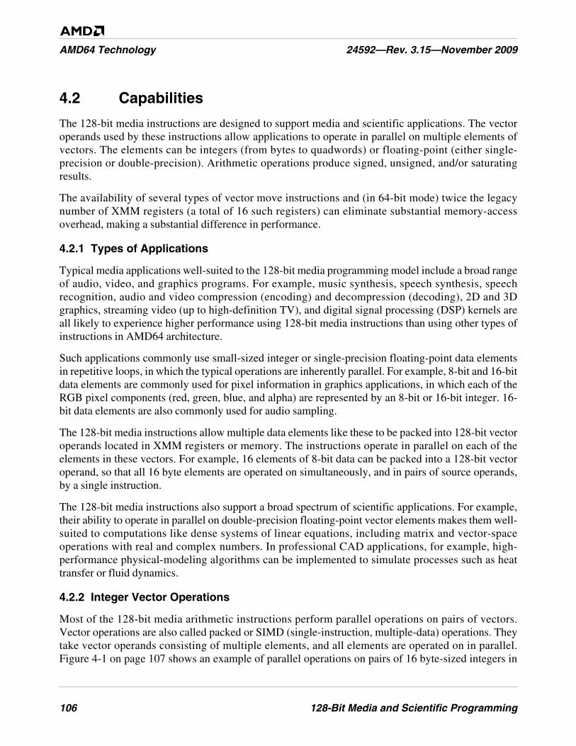
106 128-Bit Media and Scientific Programming
AMD64 Technology 24592—Rev. 3.15—November 2009
4.2 Capabilities
The 128-bit media instructions are designed to support media and scientific applications. The vectoroperands used by these instructions allow applications to operate in parallel on multiple elements ofvectors. The elements can be integers (from bytes to quadwords) or floating-point (either single-precision or double-precision). Arithmetic operations produce signed, unsigned, and/or saturatingresults.
The availability of several types of vector move instructions and (in 64-bit mode) twice the legacynumber of XMM registers (a total of 16 such registers) can eliminate substantial memory-accessoverhead, making a substantial difference in performance.
4.2.1 Types of Applications
Typical media applications well-suited to the 128-bit media programming model include a broad rangeof audio, video, and graphics programs. For example, music synthesis, speech synthesis, speechrecognition, audio and video compression (encoding) and decompression (decoding), 2D and 3Dgraphics, streaming video (up to high-definition TV), and digital signal processing (DSP) kernels areall likely to experience higher performance using 128-bit media instructions than using other types ofinstructions in AMD64 architecture.
Such applications commonly use small-sized integer or single-precision floating-point data elementsin repetitive loops, in which the typical operations are inherently parallel. For example, 8-bit and 16-bitdata elements are commonly used for pixel information in graphics applications, in which each of theRGB pixel components (red, green, blue, and alpha) are represented by an 8-bit or 16-bit integer. 16-bit data elements are also commonly used for audio sampling.
The 128-bit media instructions allow multiple data elements like these to be packed into 128-bit vectoroperands located in XMM registers or memory. The instructions operate in parallel on each of theelements in these vectors. For example, 16 elements of 8-bit data can be packed into a 128-bit vectoroperand, so that all 16 byte elements are operated on simultaneously, and in pairs of source operands,by a single instruction.
The 128-bit media instructions also support a broad spectrum of scientific applications. For example,their ability to operate in parallel on double-precision floating-point vector elements makes them well-suited to computations like dense systems of linear equations, including matrix and vector-spaceoperations with real and complex numbers. In professional CAD applications, for example, high-performance physical-modeling algorithms can be implemented to simulate processes such as heattransfer or fluid dynamics.
4.2.2 Integer Vector Operations
Most of the 128-bit media arithmetic instructions perform parallel operations on pairs of vectors.Vector operations are also called packed or SIMD (single-instruction, multiple-data) operations. Theytake vector operands consisting of multiple elements, and all elements are operated on in parallel.Figure 4-1 on page 107 shows an example of parallel operations on pairs of 16 byte-sized integers in
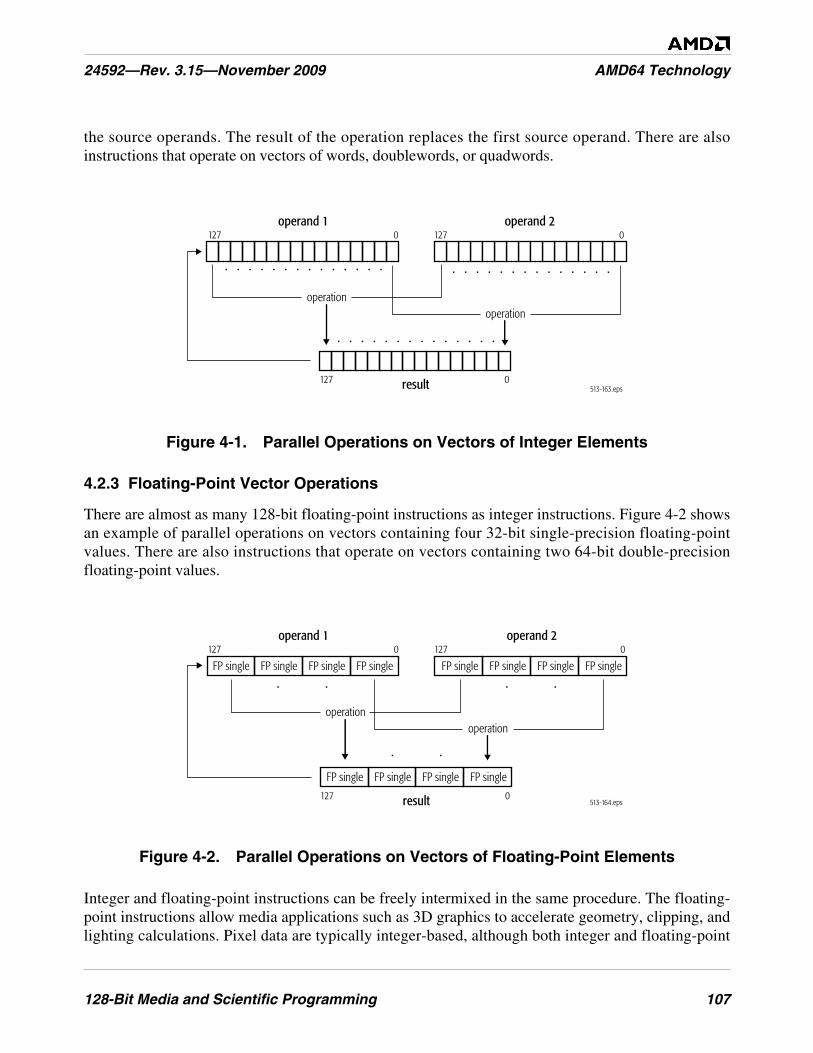
128-Bit Media and Scientific Programming 107
24592—Rev. 3.15—November 2009 AMD64 Technology
the source operands. The result of the operation replaces the first source operand. There are alsoinstructions that operate on vectors of words, doublewords, or quadwords.
Figure 4-1. Parallel Operations on Vectors of Integer Elements
4.2.3 Floating-Point Vector Operations
There are almost as many 128-bit floating-point instructions as integer instructions. Figure 4-2 showsan example of parallel operations on vectors containing four 32-bit single-precision floating-pointvalues. There are also instructions that operate on vectors containing two 64-bit double-precisionfloating-point values.
Figure 4-2. Parallel Operations on Vectors of Floating-Point Elements
Integer and floating-point instructions can be freely intermixed in the same procedure. The floating-point instructions allow media applications such as 3D graphics to accelerate geometry, clipping, andlighting calculations. Pixel data are typically integer-based, although both integer and floating-point
operand 1
. . . . . . . . . . . . . .. . . . . . . . . . . . . .
. . . . . . . . . . . . . .
127 0operand 2
127 0
operationoperation
513-163.epsresult127 0
513-164.eps
. .. .
. .
operationoperation
result
operand 1127 0
127 0
operand 2127 0
FP single FP single FP single FP single FP single FP single FP single FP single
FP single FP single FP single FP single
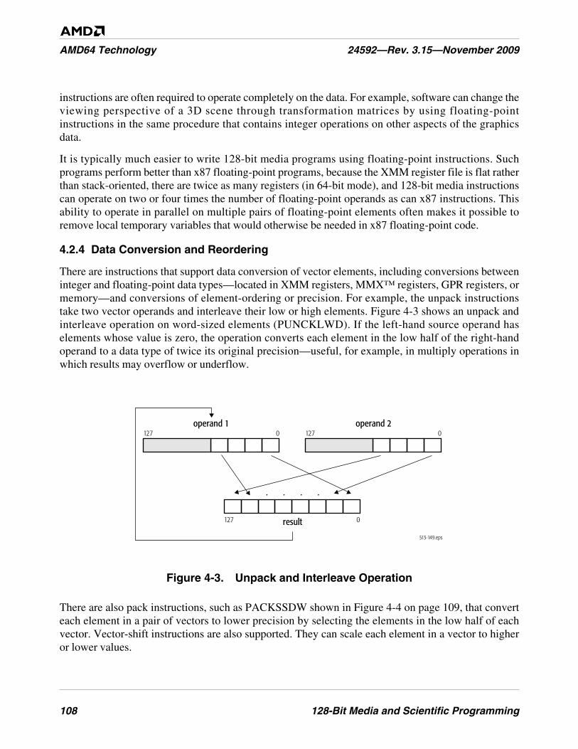
108 128-Bit Media and Scientific Programming
AMD64 Technology 24592—Rev. 3.15—November 2009
instructions are often required to operate completely on the data. For example, software can change theviewing perspective of a 3D scene through transformation matrices by using floating-pointinstructions in the same procedure that contains integer operations on other aspects of the graphicsdata.
It is typically much easier to write 128-bit media programs using floating-point instructions. Suchprograms perform better than x87 floating-point programs, because the XMM register file is flat ratherthan stack-oriented, there are twice as many registers (in 64-bit mode), and 128-bit media instructionscan operate on two or four times the number of floating-point operands as can x87 instructions. Thisability to operate in parallel on multiple pairs of floating-point elements often makes it possible toremove local temporary variables that would otherwise be needed in x87 floating-point code.
4.2.4 Data Conversion and Reordering
There are instructions that support data conversion of vector elements, including conversions betweeninteger and floating-point data types—located in XMM registers, MMX™ registers, GPR registers, ormemory—and conversions of element-ordering or precision. For example, the unpack instructionstake two vector operands and interleave their low or high elements. Figure 4-3 shows an unpack andinterleave operation on word-sized elements (PUNCKLWD). If the left-hand source operand haselements whose value is zero, the operation converts each element in the low half of the right-handoperand to a data type of twice its original precision—useful, for example, in multiply operations inwhich results may overflow or underflow.
Figure 4-3. Unpack and Interleave Operation
There are also pack instructions, such as PACKSSDW shown in Figure 4-4 on page 109, that converteach element in a pair of vectors to lower precision by selecting the elements in the low half of eachvector. Vector-shift instructions are also supported. They can scale each element in a vector to higheror lower values.
513-149.eps
operand 1
result
127 0operand 2
127 0
127 0
. .. .
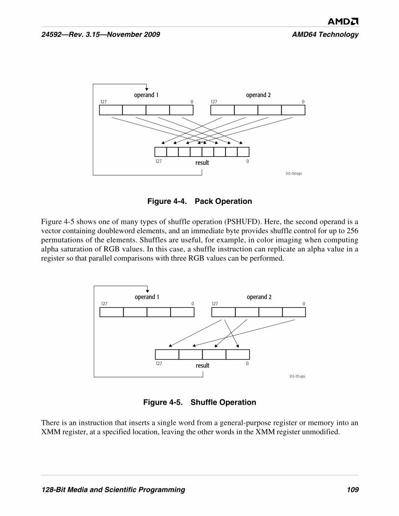
128-Bit Media and Scientific Programming 109
24592—Rev. 3.15—November 2009 AMD64 Technology
Figure 4-4. Pack Operation
Figure 4-5 shows one of many types of shuffle operation (PSHUFD). Here, the second operand is avector containing doubleword elements, and an immediate byte provides shuffle control for up to 256permutations of the elements. Shuffles are useful, for example, in color imaging when computingalpha saturation of RGB values. In this case, a shuffle instruction can replicate an alpha value in aregister so that parallel comparisons with three RGB values can be performed.
Figure 4-5. Shuffle Operation
There is an instruction that inserts a single word from a general-purpose register or memory into anXMM register, at a specified location, leaving the other words in the XMM register unmodified.
513-150.eps
operand 1
result
127 0
127 0
operand 2127 0
513-151.eps
result
operand 1127 0
127 0
operand 2127 0

110 128-Bit Media and Scientific Programming
AMD64 Technology 24592—Rev. 3.15—November 2009
4.2.5 Block Operations
Move instructions—along with unpack instructions—are among the most frequently used instructionsin 128-bit media procedures. Figure 4-6 on page 111 shows the combined set of move operationssupported by the integer and floating-point move instructions. These instructions provide a fast way tocopy large amounts of data between registers or between registers and memory. They support blockcopies and sequential processing of contiguous data.
When moving between XMM registers, or between an XMM register and memory, each integer moveinstruction can copy up to 16 bytes of data. When moving between an XMM register and an MMX orGPR register, an integer move instruction can move 8 bytes of data. The floating-pointmove instructions can copy vectors of four single-precision or two double-precision floating-pointoperands in parallel.
Streaming-store versions of the move instructions permit bypassing the cache when storing data that isaccessed only once. This maximizes memory-bus utilization and minimizes cache pollution. There isalso a streaming-store integer move-mask instruction that stores bytes from one vector, as selected bymask values in a second vector. Figure 4-7 on page 112 shows the MASKMOVDQU operation. It canbe used, for example, to handle end cases in block copies and block fills based on streaming stores.
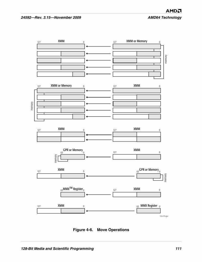
128-Bit Media and Scientific Programming 111
24592—Rev. 3.15—November 2009 AMD64 Technology
Figure 4-6. Move Operations
513-171.eps
127 0127 0
mem
ory
XMMXMM
XMM or MemoryXMM
127 0127 0
127 0127 0
mem
ory
XMMXMM or Memory
XMMGPR or Memory127 063 0
mem
ory
XMM GPR or Memory127 0 63 0
mem
ory
XMMMMXTM Register 127 063 0
XMM MMX Register127 0 63 0
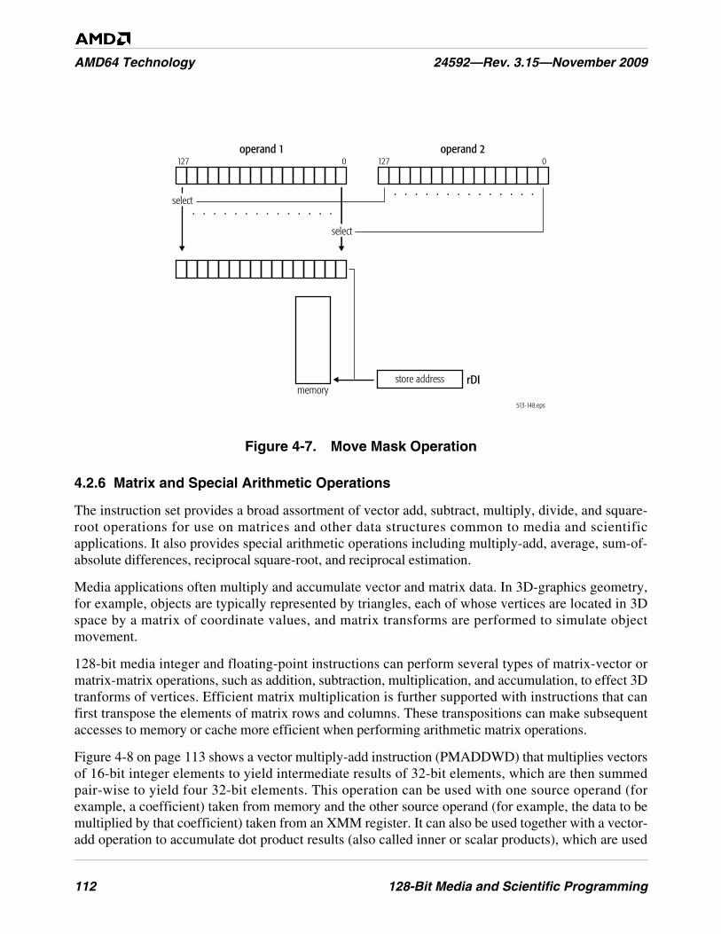
112 128-Bit Media and Scientific Programming
AMD64 Technology 24592—Rev. 3.15—November 2009
Figure 4-7. Move Mask Operation
4.2.6 Matrix and Special Arithmetic Operations
The instruction set provides a broad assortment of vector add, subtract, multiply, divide, and square-root operations for use on matrices and other data structures common to media and scientificapplications. It also provides special arithmetic operations including multiply-add, average, sum-of-absolute differences, reciprocal square-root, and reciprocal estimation.
Media applications often multiply and accumulate vector and matrix data. In 3D-graphics geometry,for example, objects are typically represented by triangles, each of whose vertices are located in 3Dspace by a matrix of coordinate values, and matrix transforms are performed to simulate objectmovement.
128-bit media integer and floating-point instructions can perform several types of matrix-vector ormatrix-matrix operations, such as addition, subtraction, multiplication, and accumulation, to effect 3Dtranforms of vertices. Efficient matrix multiplication is further supported with instructions that canfirst transpose the elements of matrix rows and columns. These transpositions can make subsequentaccesses to memory or cache more efficient when performing arithmetic matrix operations.
Figure 4-8 on page 113 shows a vector multiply-add instruction (PMADDWD) that multiplies vectorsof 16-bit integer elements to yield intermediate results of 32-bit elements, which are then summedpair-wise to yield four 32-bit elements. This operation can be used with one source operand (forexample, a coefficient) taken from memory and the other source operand (for example, the data to bemultiplied by that coefficient) taken from an XMM register. It can also be used together with a vector-add operation to accumulate dot product results (also called inner or scalar products), which are used
operand 1
. . . . . . . . . . . . . .
. . . . . . . . . . . . . .
127 0operand 2
127 0
select
select
store addressmemory
rDI
513-148.eps
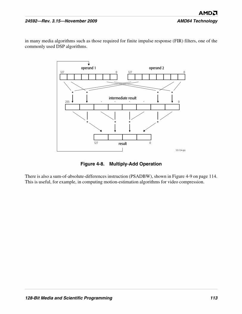
128-Bit Media and Scientific Programming 113
24592—Rev. 3.15—November 2009 AMD64 Technology
in many media algorithms such as those required for finite impulse response (FIR) filters, one of thecommonly used DSP algorithms.
Figure 4-8. Multiply-Add Operation
There is also a sum-of-absolute-differences instruction (PSADBW), shown in Figure 4-9 on page 114.This is useful, for example, in computing motion-estimation algorithms for video compression.
513-154.eps
operand 1
result
127 0operand 2
127 0
127 0
intermediate result255 0
* ***
. . . .
+ ++ +
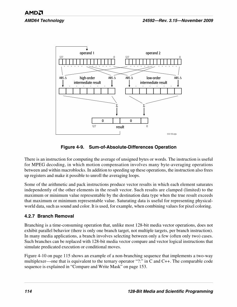
114 128-Bit Media and Scientific Programming
AMD64 Technology 24592—Rev. 3.15—November 2009
Figure 4-9. Sum-of-Absolute-Differences Operation
There is an instruction for computing the average of unsigned bytes or words. The instruction is usefulfor MPEG decoding, in which motion compensation involves many byte-averaging operationsbetween and within macroblocks. In addition to speeding up these operations, the instruction also freesup registers and make it possible to unroll the averaging loops.
Some of the arithmetic and pack instructions produce vector results in which each element saturatesindependently of the other elements in the result vector. Such results are clamped (limited) to themaximum or minimum value representable by the destination data type when the true result exceedsthat maximum or minimum representable value. Saturating data is useful for representing physical-world data, such as sound and color. It is used, for example, when combining values for pixel coloring.
4.2.7 Branch Removal
Branching is a time-consuming operation that, unlike most 128-bit media vector operations, does notexhibit parallel behavior (there is only one branch target, not multiple targets, per branch instruction).In many media applications, a branch involves selecting between only a few (often only two) cases.Such branches can be replaced with 128-bit media vector compare and vector logical instructions thatsimulate predicated execution or conditional moves.
Figure 4-10 on page 115 shows an example of a non-branching sequence that implements a two-waymultiplexer—one that is equivalent to the ternary operator “?:” in C and C++. The comparable codesequence is explained in “Compare and Write Mask” on page 153.
513-155.eps
operand 1
. . . . . .. . . . . .. . . . . .. . . . . .
. . . . . . . . . . . .
127 0operand 2
127 0
result
00127 0
low-orderintermediate result
high-orderintermediate result
ABS ΔABS Δ
ΣΣ
ABS Δ ABS Δ
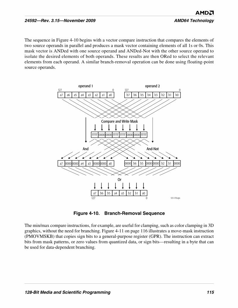
128-Bit Media and Scientific Programming 115
24592—Rev. 3.15—November 2009 AMD64 Technology
The sequence in Figure 4-10 begins with a vector compare instruction that compares the elements oftwo source operands in parallel and produces a mask vector containing elements of all 1s or 0s. Thismask vector is ANDed with one source operand and ANDed-Not with the other source operand toisolate the desired elements of both operands. These results are then ORed to select the relevantelements from each operand. A similar branch-removal operation can be done using floating-pointsource operands.
Figure 4-10. Branch-Removal Sequence
The min/max compare instructions, for example, are useful for clamping, such as color clamping in 3Dgraphics, without the need for branching. Figure 4-11 on page 116 illustrates a move-mask instruction(PMOVMSKB) that copies sign bits to a general-purpose register (GPR). The instruction can extractbits from mask patterns, or zero values from quantized data, or sign bits—resulting in a byte that canbe used for data-dependent branching.
513-170.eps
operand 1 operand 2
FFFF 0000 0000 FFFFFFFF 0000 0000 FFFF
a3 a2 a1 a0a7 a6 a5 a4 b3 b2 b1 b0b7 b6 b5 b4
a3 0000 0000 a0a7 0000 0000 a4 0000 b2 b1 00000000 b6 b5 0000
And And-Not
Compare and Write Mask
a3 b2 b1 a0a7 b6 b5 a4
Or
127 0 127 0
127 0
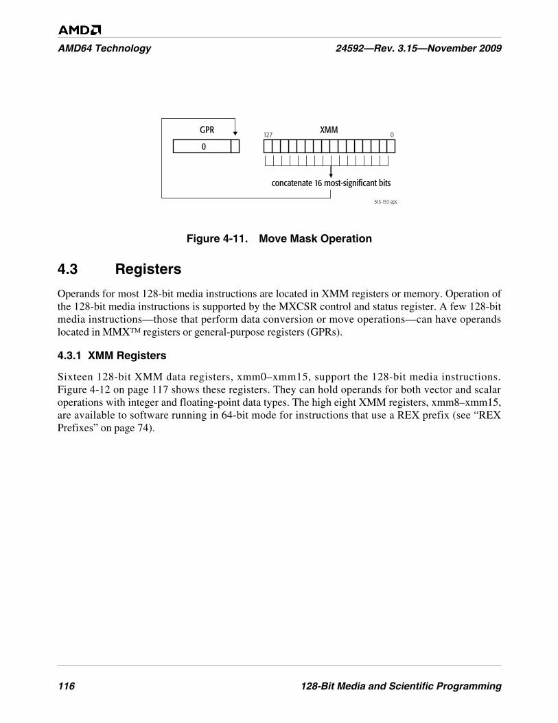
116 128-Bit Media and Scientific Programming
AMD64 Technology 24592—Rev. 3.15—November 2009
Figure 4-11. Move Mask Operation
4.3 Registers
Operands for most 128-bit media instructions are located in XMM registers or memory. Operation ofthe 128-bit media instructions is supported by the MXCSR control and status register. A few 128-bitmedia instructions—those that perform data conversion or move operations—can have operandslocated in MMX™ registers or general-purpose registers (GPRs).
4.3.1 XMM Registers
Sixteen 128-bit XMM data registers, xmm0–xmm15, support the 128-bit media instructions.Figure 4-12 on page 117 shows these registers. They can hold operands for both vector and scalaroperations with integer and floating-point data types. The high eight XMM registers, xmm8–xmm15,are available to software running in 64-bit mode for instructions that use a REX prefix (see “REXPrefixes” on page 74).
513-157..eps
GPR XMM127 0
concatenate 16 most-significant bits
0
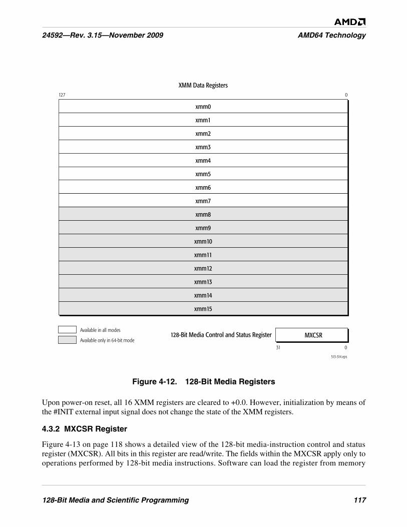
128-Bit Media and Scientific Programming 117
24592—Rev. 3.15—November 2009 AMD64 Technology
Figure 4-12. 128-Bit Media Registers
Upon power-on reset, all 16 XMM registers are cleared to +0.0. However, initialization by means ofthe #INIT external input signal does not change the state of the XMM registers.
4.3.2 MXCSR Register
Figure 4-13 on page 118 shows a detailed view of the 128-bit media-instruction control and statusregister (MXCSR). All bits in this register are read/write. The fields within the MXCSR apply only tooperations performed by 128-bit media instructions. Software can load the register from memory
513-314.eps
XMM Data Registers127 0
xmm0
xmm1
xmm2
xmm3
xmm4
xmm5
xmm6
xmm7
xmm8
xmm9
xmm10
xmm11
xmm12
xmm13
xmm14
xmm15
Available in all modes
Available only in 64-bit mode31 0
MXCSR128-Bit Media Control and Status Register

118 128-Bit Media and Scientific Programming
AMD64 Technology 24592—Rev. 3.15—November 2009
using the FXRSTOR or LDMXCSR instructions, and it can store the register to memory using theFXSAVE or STMXCSR instructions.
Figure 4-13. 128-Bit Media Control and Status Register (MXCSR)
On power-on reset, all bits are initialized to the values provided in Figure 4-13. However, initializationby means of the #INIT external input signal does not change the state of the XMM registers.
The six exception flags (IE, DE, ZE, OE, UE, PE) are sticky bits. (Once set by the processor, such a bitremains set until software clears it.) For details about the causes of SIMD floating-point exceptionsindicated by bits 5–0, see “SIMD Floating-Point Exception Causes” on page 178. For details about themasking of these exceptions, see “SIMD Floating-Point Exception Masking” on page 184.
Invalid-Operation Exception (IE). Bit 0. The processor sets this bit to 1 when an invalid-operationexception occurs. These exceptions are caused by many types of errors, such as an invalid operand.
Denormalized-Operand Exception (DE). Bit 1. The processor sets this bit to 1 when one of thesource operands of an instruction is in denormalized form, except that if software has set the
31 18 17 16 15 14 13 12 11 10 9 8 7 6 5 4 3 2 1 0
Reserved, MBZMM
Res
FZ
RC
PM
UM
OM
ZM
DM
IM
DAZ
PE
UE
OE
ZE
DE
IE
Bits Mnemonic Description Reset Bit-Value31–18 – Reserved, MBZ
17 MM Misaligned Exception Mask 016 – Reserved, MBZ15 FZ Flush-to-Zero for Masked Underflow 0
14–13 RC Floating-Point Rounding Control 00Exception Masks
12 PM Precision Exception Mask 111 UM Underflow Exception Mask 110 OM Overflow Exception Mask 19 ZM Zero-Divide Exception Mask 18 DM Denormalized-Operand Exception Mask 17 IM Invalid-Operation Exception Mask 16 DAZ Denormals Are Zeros 0
Exception Flags5 PE Precision Exception 04 UE Underflow Exception 03 OE Overflow Exception 02 ZE Zero-Divide Exception 01 DE Denormalized-Operand Exception 00 IE Invalid-Operation Exception 0

128-Bit Media and Scientific Programming 119
24592—Rev. 3.15—November 2009 AMD64 Technology
denormals are zeros (DAZ) bit, the processor does not set the DE bit. (See “Denormalized (Tiny)Numbers” on page 128.)
Zero-Divide Exception (ZE). Bit 2. The processor sets this bit to 1 when a non-zero number isdivided by zero.
Overflow Exception (OE). Bit 3. The processor sets this bit to 1 when the absolute value of arounded result is larger than the largest representable normalized floating-point number for thedestination format. (See “Normalized Numbers” on page 128.)
Underflow Exception (UE). Bit 4. The processor sets this bit to 1 when the absolute value of arounded non-zero result is too small to be represented as a normalized floating-point number for thedestination format. (See “Normalized Numbers” on page 128.)
When masked by the UM bit (bit 11), the processor only reports a UE exception if the UE occurstogether with a precision exception (PE). Also, see bit 15, the flush-to-zero (FZ) bit.
Precision Exception (PE). Bit 5. The processor sets this bit to 1 when a floating-point result, afterrounding, differs from the infinitely precise result and thus cannot be represented exactly in thespecified destination format. The PE exception is also called the inexact-result exception.
Denormals Are Zeros (DAZ). Bit 6. Software can set this bit to 1 to enable the DAZ mode, if thehardware implementation supports this mode. In the DAZ mode, when the processor encounterssource operands in the denormalized format it converts them to signed zero values, with the sign of thedenormalized source operand, before operating on them, and the processor does not set thedenormalized-operand exception (DE) bit, regardless of whether such exceptions are masked orunmasked.
Support for the DAZ bit is indicated by the MXCSR Mask field in the FXSAVE memory image, asdescribed in “FXSAVE and FXRSTOR Instructions” in Volume 2. The DAZ mode does not complywith the IEEE Standard for Binary Floating-Point Arithmetic (ANSI/IEEE Std 754).
Exception Masks (PM, UM, OM, ZM, DM, IM). Bits 12–7. Software can set these bits to mask, orclear this bits to unmask, the corresponding six types of SIMD floating-point exceptions (PE, UE, OE,ZE, DE, IE). A bit masks its exception type when set to 1, and unmasks it when cleared to 0.
In general, masking a type of exception causes the processor to handle all subsequent instances of theexception type in a default way (the UE exception has an unusual behavior). Unmasking the exceptiontype causes the processor to branch to the SIMD floating-point exception service routine when anexception occurs. For details about the processor’s responses to masked and unmasked exceptions, see“SIMD Floating-Point Exception Masking” on page 184.
Floating-Point Rounding Control (RC). Bit 14–13. Software uses these bits to specify the roundingmethod for 128-bit media floating-point operations. The choices are:
• 00 = round to nearest (default)
• 01 = round down
120 128-Bit Media and Scientific Programming
AMD64 Technology 24592—Rev. 3.15—November 2009
• 10 = round up
• 11 = round toward zero
For details, see “Floating-Point Rounding” on page 132.
Flush-to-Zero (FZ). Bit 15. If the rounded result is tiny and the underflow mask is set, the FTZ bitcauses the result to be flushed to zero. This naturally causes the result to be inexact, which causes bothPE and UE to be set. The sign returned with the zero is the sign of the true result. The FTZ bit does nothave any effect if the underflow mask is 0.
This response does not comply with the IEEE 754 standard, but it may offer higher performance thancan be achieved by responding to an underflow in this circumstance. The FZ bit is only effective if theUM bit is set to 1. If the UM bit is cleared to 0, the FZ bit is ignored. For details, see Table 4-14 onpage 185.
Misaligned Exception Mask (MM). Bit 17. If the misaligned exception mask (MM) is set to 1, a 16-byte misaligned memory access on most packed SSE instructions will not cause a #GP exception, butwill be subject to alignment checking (#AC) instead. When MM is set and alignment-checking isenabled, a #AC exception is generated, if the memory operand is not 16-byte aligned. Thecorresponding MXCSR_MASK bit (17) is 1, regardless of whether MM is set or not. For details onMXCSR and MXCSR_MASK, see “128-Bit, 64-Bit, and x87 Programming” in the AMD64Architecture Programmer’s Manual Volume 2: System Programming, order #24593. For details onalignment handling, see “Data Alignment” on page 123.
Support for misaligned SSE mode is indicated by ECX bit 7 of CPUID function 8000_0001h.
4.3.3 Other Data Registers
Some 128-bit media instructions that perform data transfer, data conversion or data reorderingoperations (“Data Transfer” on page 135, “Data Conversion” on page 139, and “Data Reordering” onpage 140) can access operands in the MMX or general-purpose registers (GPRs). When addressingGPRs registers in 64-bit mode, the REX instruction prefix can be used to access the extended GPRs, asdescribed in “REX Prefixes” on page 74.
For a description of the GPR registers, see “Registers” on page 23. For a description of the MMXregisters, see “MMX™ Registers” on page 200.
4.3.4 rFLAGS Registers
The COMISS, COMISD, UCOMISS, and UCOMISD instructions, described in “Compare” onpage 171, write flag bits in the rFLAGS register. For a description of the rFLAGS register, see “FlagsRegister” on page 33.

128-Bit Media and Scientific Programming 121
24592—Rev. 3.15—November 2009 AMD64 Technology
4.4 Operands
Operands for a 128-bit media instruction are either referenced by the instruction's opcode or includedas an immediate value in the instruction encoding. Depending on the instruction, referenced operandscan be located in registers or memory. The data types of these operands include vector and scalarfloating-point, and vector and scalar integer.
4.4.1 Data Types
Figure 4-14 on page 122 shows the register images of the 128-bit media data types. These data typescan be interpreted by instruction syntax and/or the software context as one of the following types ofvalues:
• Vector (packed) single-precision (32-bit) floating-point numbers.
• Vector (packed) double-precision (64-bit) floating-point numbers.
• Vector (packed) signed (two's-complement) integers.
• Vector (packed) unsigned integers.
• Scalar signed (two's-complement) integers.
• Scalar unsigned integers.
Hardware does not check or enforce the data types for instructions. Software is responsible forensuring that each operand for an instruction is of the correct data type. If data produced by a previousinstruction is of a type different from that used by the current instruction, and the current instructionsources such data, the current instruction may incur a latency penalty, depending on the hardwareimplementation.
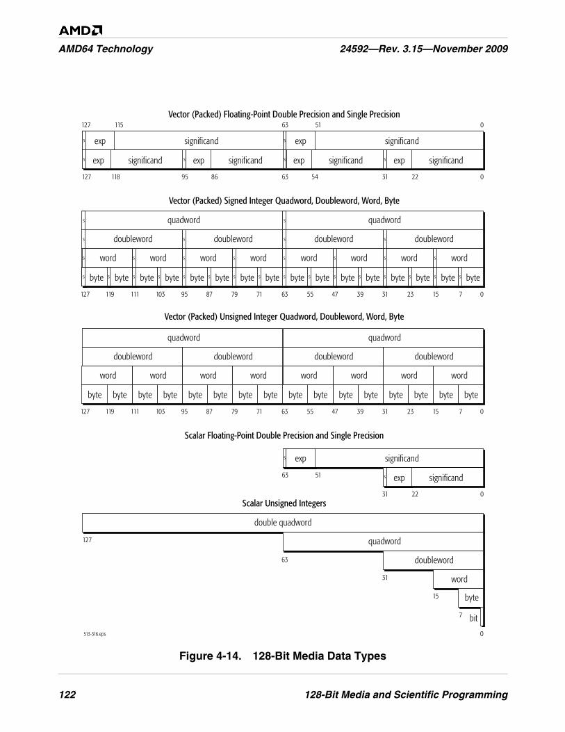
122 128-Bit Media and Scientific Programming
AMD64 Technology 24592—Rev. 3.15—November 2009
Figure 4-14. 128-Bit Media Data Types
ssss
ss
ssss
ss
ssssssss
ssss
ss
ssssssssssssssss
ssssssss
ssss
ss
ssssssssssssssss
513-316.eps
71523313947556371798795103111119127 0
bytebytebytebytebytebytebytebytebytebytebytebytebytebytebytebyte
31 2263 5495 86127 118 0
Vector (Packed) Floating-Point Double Precision and Single Precision
Vector (Packed) Unsigned Integer Quadword, Doubleword, Word, Byte
71523313947556371798795103111119127 0
quadwordquadword
doubleworddoubleworddoubleworddoubleword
wordwordwordwordwordwordwordword
quadwordquadword
doubleworddoubleworddoubleworddoubleword
wordwordwordwordwordwordwordword
127 0
Scalar Unsigned Integers
127
double quadword
bytebytebytebytebytebytebytebytebytebytebytebytebytebytebytebyte
Vector (Packed) Signed Integer Quadword, Doubleword, Word, Byte
significand
exp significand
063 51127 115
exp significand
expsignificandexpsignificandexpsignificandexp
s
s
s
s
31 22 0
Scalar Floating-Point Double Precision and Single Precision
significand
exp significand
63 51 exp
15
31
63
quadword
doubleword
word
7
0
byte
bit
128-Bit Media and Scientific Programming 123
24592—Rev. 3.15—November 2009 AMD64 Technology
Software can interpret the data types in ways other than those shown in Figure 4-14 on page 122—such as bit fields or fractional numbers—but the 128-bit media instructions do not directly supportsuch interpretations and software must handle them entirely on its own.
4.4.2 Operand Sizes and Overrides
Operand sizes for 128-bit media instructions are determined by instruction opcodes. Some of theseopcodes include an operand-size override prefix, but this prefix acts in a special way to modify theopcode and is considered an integral part of the opcode. The general use of the 66h operand-sizeoverride prefix described in “Instruction Prefixes” on page 71 does not apply to 128-bit mediainstructions.
For details on the use of operand-size override prefixes in 128-bit media instructions, see the opcodesin “128-Bit Media Instruction Reference” in Volume 4.
4.4.3 Operand Addressing
Depending on the 128-bit media instruction, referenced operands may be in registers or memory.
Register Operands. Most 128-bit media instructions can access source and destination operands inXMM registers. A few of these instructions access the MMX registers, GPR registers, rFLAGSregister, or MXCSR register. The type of register addressed is specified in the instruction syntax.When addressing GPR or XMM registers, the REX instruction prefix can be used to access theextended GPR or XMM registers, as described in “Instruction Prefixes” on page 175.
Memory Operands. Most 128-bit media instructions can read memory for source operands, andsome of the instructions can write results to memory. “Memory Addressing” on page 14, describes thegeneral methods for addressing memory operands.
Immediate Operands. Immediate operands are used in certain data-conversion, vector-shift, andvector-compare instructions. Such instructions take 8-bit immediates, which provide control for theoperation.
I/O Ports. I/O ports in the I/O address space cannot be directly addressed by 128-bit mediainstructions, and although memory-mapped I/O ports can be addressed by such instructions, doing somay produce unpredictable results, depending on the hardware implementation of the architecture.
4.4.4 Data Alignment
Generally, 128-bit media instructions that access a 128-bit operand in memory trigger a general-protection exception (#GP) if the operand is not aligned to a 16-byte boundary. For instance, 128-bitmedia instructions that manipulate scalar operands never trigger a #GP, nor do the followinginstructions:
• MASKMOVDQU—Masked Move Double Quadword Unaligned.
• MOVDQU—Move Unaligned Double Quadword.
• MOVUPD—Move Unaligned Packed Double-Precision Floating-Point.
124 128-Bit Media and Scientific Programming
AMD64 Technology 24592—Rev. 3.15—November 2009
• MOVUPS—Move Unaligned Packed Single-Precision Floating-Point.
• LDDQU—Load Unaligned Double Quadword
When alignment checking is enabled (CR0.AM = 1 and rFLAGS.AC = 1) and the MXCSR misalignedexception mask (MM) bit is set to 1, a 16-byte misaligned memory access on most packed SSEinstructions will not cause a #GP exception, but a #AC exception is generated instead. On the otherhand, if MM is cleared to 0, then a 16-byte misaligned memory access will cause a #GP exception.Keep in mind that the corresponding MXCSR_MASK bit (17) is 1, regardless of whether MM is set ornot. For details on MXCSR and MXCSR_MASK, see “128-Bit, 64-Bit, and x87 Programming” in theAMD64 Architecture Programmer’s Manual Volume 2: System Programming, order #24593.
The FXSAVE, FXRSTOR, MOVAPD, MOVAPS, and MOVDQA, MOVNTDQ, MOVNTPD andMOVNTPS instructions do not support misaligned accesses. These instructions always generate a #GPexception if misaligned on a 16-byte boundary.
While the architecture does not impose data-alignment requirements for 128-bit media instructions,the consequence of storing operands at unaligned locations is that accesses to those operands mayrequire more processor and bus cycles than for aligned accesses. See “Data Alignment” on page 40 fordetails.
Support for misaligned SSE mode is indicated by ECX bit 7 of CPUID function 8000_0001h.
4.4.5 Integer Data Types
The 128-bit media instructions that support operations on integer data types are summarized in“Instruction Summary—Integer Instructions” on page 133. The characteristics of these data types aredescribed below.
Sign. Many of the 128-bit media instructions have variants for operating on signed or unsignedintegers. For signed integers, the sign bit is the most-significant bit—bit 7 for a byte, bit 15 for a word,bit 31 for a doubleword, bit 63 for a quadword, or bit 127 for a double quadword. Arithmeticinstructions that are not specifically named as unsigned perform signed two’s-complement arithmetic.
Range of Representable Values. Table 4-1 on page 125 shows the range of representable values forthe integer data types.
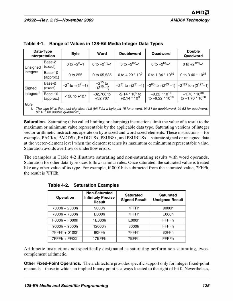
128-Bit Media and Scientific Programming 125
24592—Rev. 3.15—November 2009 AMD64 Technology
Saturation. Saturating (also called limiting or clamping) instructions limit the value of a result to themaximum or minimum value representable by the applicable data type. Saturating versions of integervector-arithmetic instructions operate on byte-sized and word-sized elements. These instructions—forexample, PACKx, PADDSx, PADDUSx, PSUBSx, and PSUBUSx—saturate signed or unsigned dataat the vector-element level when the element reaches its maximum or minimum representable value.Saturation avoids overflow or underflow errors.
The examples in Table 4-2 illustrate saturating and non-saturating results with word operands.Saturation for other data-type sizes follows similar rules. Once saturated, the saturated value is treatedlike any other value of its type. For example, if 0001h is subtracted from the saturated value, 7FFFh,the result is 7FFEh.
Arithmetic instructions not specifically designated as saturating perform non-saturating, twos-complement arithmetic.
Other Fixed-Point Operands. The architecture provides specific support only for integer fixed-pointoperands—those in which an implied binary point is always located to the right of bit 0. Nevertheless,
Table 4-1. Range of Values in 128-Bit Media Integer Data Types
Data-TypeInterpretation
Byte Word Doubleword QuadwordDouble
Quadword
Unsignedintegers
Base-2(exact)
0 to +28–1 0 to +216–1 0 to +232–1 0 to +264–1 0 to +2128–1
Base-10(approx.)
0 to 255 0 to 65,535 0 to 4.29 * 109 0 to 1.84 * 1019 0 to 3.40 * 1038
Signed
integers1
Base-2(exact)
–27 to +(27 –1) –215 to+(215–1) –231 to +(231 –1) –263 to +(263 –1) –2127 to +(2127–1)
Base-10(approx.)
-128 to +127 -32,768 to+32,767
-2.14 * 109 to+2.14 * 109
–9.22 * 1018
to +9.22 * 1018–1.70 * 1038
to +1.70 * 1038
Note:1. The sign bit is the most-significant bit (bit 7 for a byte, bit 15 for a word, bit 31 for doubleword, bit 63 for quadword,
bit 127 for double quadword.).
Table 4-2. Saturation Examples
OperationNon-Saturated
Infinitely PreciseResult
SaturatedSigned Result
SaturatedUnsigned Result
7000h + 2000h 9000h 7FFFh 9000h
7000h + 7000h E000h 7FFFh E000h
F000h + F000h 1E000h E000h FFFFh
9000h + 9000h 12000h 8000h FFFFh
7FFFh + 0100h 80FFh 7FFFh 80FFh
7FFFh + FF00h 17EFFh 7EFFh FFFFh
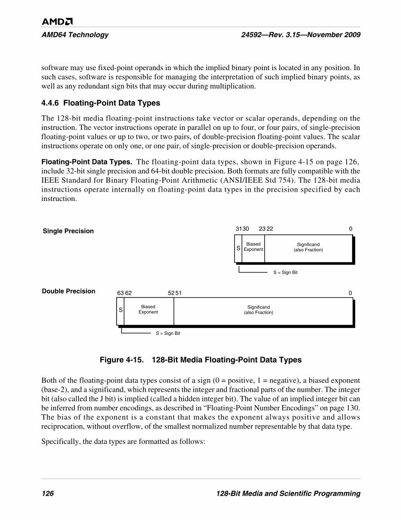
126 128-Bit Media and Scientific Programming
AMD64 Technology 24592—Rev. 3.15—November 2009
software may use fixed-point operands in which the implied binary point is located in any position. Insuch cases, software is responsible for managing the interpretation of such implied binary points, aswell as any redundant sign bits that may occur during multiplication.
4.4.6 Floating-Point Data Types
The 128-bit media floating-point instructions take vector or scalar operands, depending on theinstruction. The vector instructions operate in parallel on up to four, or four pairs, of single-precisionfloating-point values or up to two, or two pairs, of double-precision floating-point values. The scalarinstructions operate on only one, or one pair, of single-precision or double-precision operands.
Floating-Point Data Types. The floating-point data types, shown in Figure 4-15 on page 126,include 32-bit single precision and 64-bit double precision. Both formats are fully compatible with theIEEE Standard for Binary Floating-Point Arithmetic (ANSI/IEEE Std 754). The 128-bit mediainstructions operate internally on floating-point data types in the precision specified by eachinstruction.
Figure 4-15. 128-Bit Media Floating-Point Data Types
Both of the floating-point data types consist of a sign (0 = positive, 1 = negative), a biased exponent(base-2), and a significand, which represents the integer and fractional parts of the number. The integerbit (also called the J bit) is implied (called a hidden integer bit). The value of an implied integer bit canbe inferred from number encodings, as described in “Floating-Point Number Encodings” on page 130.The bias of the exponent is a constant that makes the exponent always positive and allowsreciprocation, without overflow, of the smallest normalized number representable by that data type.
Specifically, the data types are formatted as follows:
063Double Precision
31 0Single Precision 2223
SBiased
Exponent
5152
BiasedExponentS
30
62
S = Sign Bit
S = Sign Bit
Significand(also Fraction)
Significand(also Fraction)
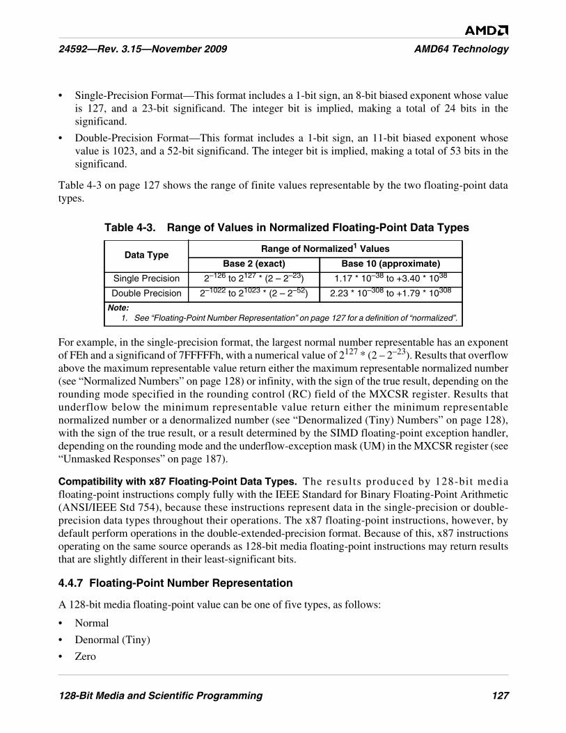
128-Bit Media and Scientific Programming 127
24592—Rev. 3.15—November 2009 AMD64 Technology
• Single-Precision Format—This format includes a 1-bit sign, an 8-bit biased exponent whose valueis 127, and a 23-bit significand. The integer bit is implied, making a total of 24 bits in thesignificand.
• Double-Precision Format—This format includes a 1-bit sign, an 11-bit biased exponent whosevalue is 1023, and a 52-bit significand. The integer bit is implied, making a total of 53 bits in thesignificand.
Table 4-3 on page 127 shows the range of finite values representable by the two floating-point datatypes.
For example, in the single-precision format, the largest normal number representable has an exponentof FEh and a significand of 7FFFFFh, with a numerical value of 2127 * (2 – 2–23). Results that overflowabove the maximum representable value return either the maximum representable normalized number(see “Normalized Numbers” on page 128) or infinity, with the sign of the true result, depending on therounding mode specified in the rounding control (RC) field of the MXCSR register. Results thatunderflow below the minimum representable value return either the minimum representablenormalized number or a denormalized number (see “Denormalized (Tiny) Numbers” on page 128),with the sign of the true result, or a result determined by the SIMD floating-point exception handler,depending on the rounding mode and the underflow-exception mask (UM) in the MXCSR register (see“Unmasked Responses” on page 187).
Compatibility with x87 Floating-Point Data Types. The results produced by 128-bit mediafloating-point instructions comply fully with the IEEE Standard for Binary Floating-Point Arithmetic(ANSI/IEEE Std 754), because these instructions represent data in the single-precision or double-precision data types throughout their operations. The x87 floating-point instructions, however, bydefault perform operations in the double-extended-precision format. Because of this, x87 instructionsoperating on the same source operands as 128-bit media floating-point instructions may return resultsthat are slightly different in their least-significant bits.
4.4.7 Floating-Point Number Representation
A 128-bit media floating-point value can be one of five types, as follows:
• Normal
• Denormal (Tiny)
• Zero
Table 4-3. Range of Values in Normalized Floating-Point Data Types
Data TypeRange of Normalized1 Values
Base 2 (exact) Base 10 (approximate)
Single Precision 2–126 to 2127 * (2 – 2–23) 1.17 * 10–38 to +3.40 * 1038
Double Precision 2–1022 to 21023 * (2 – 2–52) 2.23 * 10–308 to +1.79 * 10308
Note:1. See “Floating-Point Number Representation” on page 127 for a definition of “normalized”.
128 128-Bit Media and Scientific Programming
AMD64 Technology 24592—Rev. 3.15—November 2009
• Infinity
• Not a Number (NaN)
In common engineering and scientific usage, floating-point numbers—also called real numbers—arerepresented in base (radix) 10. A non-zero number consists of a sign, a normalized significand, and asigned exponent, as in:
+2.71828 e0
Both large and small numbers are representable in this notation, subject to the limits of data-typeprecision. For example, a million in base-10 notation appears as +1.00000 e6 and -0.0000383 isrepresented as -3.83000 e-5. A non-zero number can always be written in normalized form—that is,with a leading non-zero digit immediately before the decimal point. Thus, a normalized significand inbase-10 notation is a number in the range [1,10). The signed exponent specifies the number ofpositions that the decimal point is shifted.
Unlike the common engineering and scientific usage described above, 128-bit media floating-pointnumbers are represented in base (radix) 2. Like its base-10 counterpart, a normalized base-2significand is written with its leading non-zero digit immediately to the left of the radix point. In base-2 arithmetic, a non-zero digit is always a one, so the range of a binary significand is [1,2):
+1.fraction ±exponent
The leading non-zero digit is called the integer bit. As shown in Figure 4-15 on page 126, the integerbit is omitted (and called the hidden integer bit) in the single-precision and the double-precisionfloating-point formats, because its implied value is always 1 in a normalized significand (0 in adenormalized significand), and the omission allows an extra bit of precision.
The following sections describe the number representations.
Normalized Numbers. Normalized floating-point numbers are the most frequent operands for 128-bit media instructions. These are finite, non-zero, positive or negative numbers in which the integer bitis 1, the biased exponent is non-zero and non-maximum, and the fraction is any representable value.Thus, the significand is within the range of [1, 2). Whenever possible, the processor represents afloating-point result as a normalized number.
Denormalized (Tiny) Numbers. Denormalized numbers (also called tiny numbers) are smaller thanthe smallest representable normalized numbers. They arise through an underflow condition, when theexponent of a result lies below the representable minimum exponent. These are finite, non-zero,positive or negative numbers in which the integer bit is 0, the biased exponent is 0, and the fraction isnon-zero.
The processor generates a denormalized-operand exception (DE) when an instruction uses adenormalized source operand. The processor may generate an underflow exception (UE) when aninstruction produces a rounded, non-zero result that is too small to be represented as a normalizedfloating-point number in the destination format, and thus is represented as a denormalized number. If aresult, after rounding, is too small to be represented as the minimum denormalized number, it isrepresented as zero. (See “Exceptions” on page 177 for specific details.)
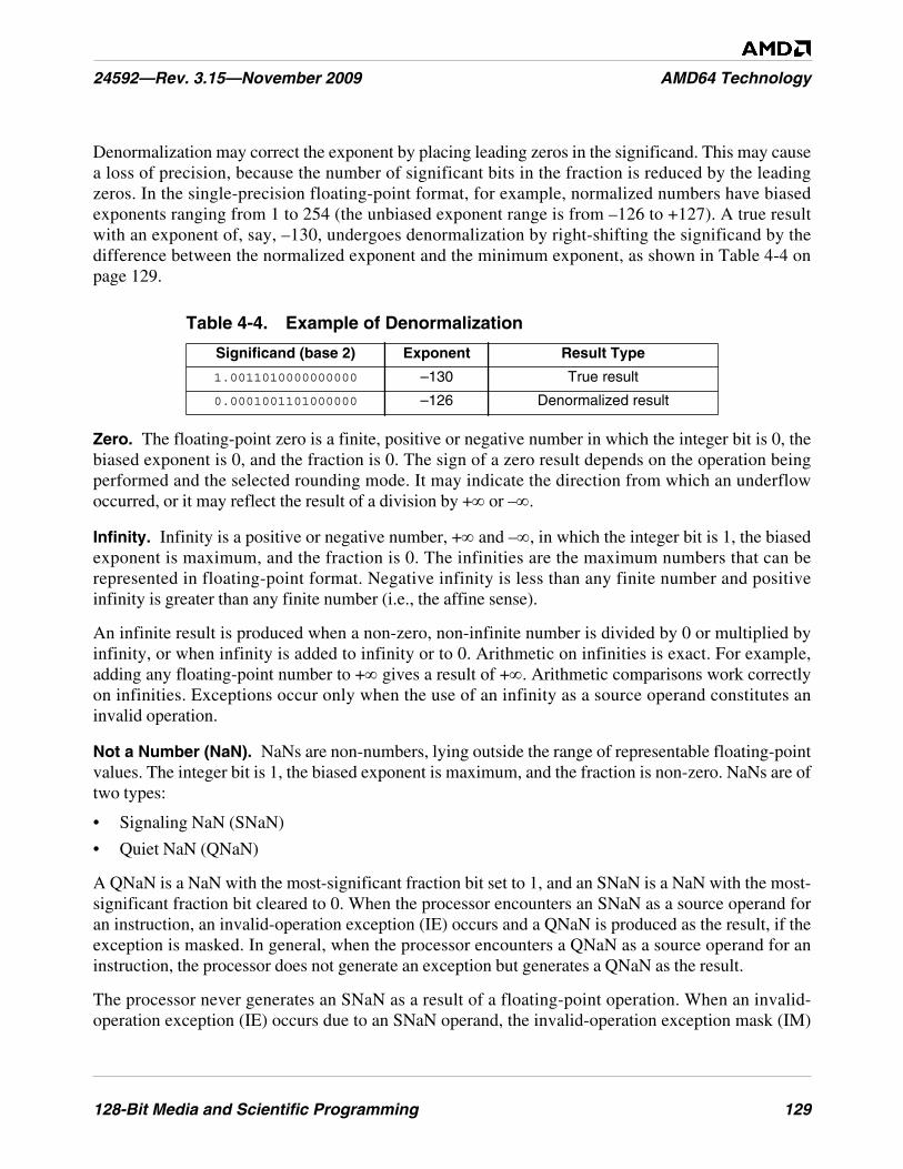
128-Bit Media and Scientific Programming 129
24592—Rev. 3.15—November 2009 AMD64 Technology
Denormalization may correct the exponent by placing leading zeros in the significand. This may causea loss of precision, because the number of significant bits in the fraction is reduced by the leadingzeros. In the single-precision floating-point format, for example, normalized numbers have biasedexponents ranging from 1 to 254 (the unbiased exponent range is from –126 to +127). A true resultwith an exponent of, say, –130, undergoes denormalization by right-shifting the significand by thedifference between the normalized exponent and the minimum exponent, as shown in Table 4-4 onpage 129.
Zero. The floating-point zero is a finite, positive or negative number in which the integer bit is 0, thebiased exponent is 0, and the fraction is 0. The sign of a zero result depends on the operation beingperformed and the selected rounding mode. It may indicate the direction from which an underflowoccurred, or it may reflect the result of a division by +∞ or –∞.
Infinity. Infinity is a positive or negative number, +∞ and –∞, in which the integer bit is 1, the biasedexponent is maximum, and the fraction is 0. The infinities are the maximum numbers that can berepresented in floating-point format. Negative infinity is less than any finite number and positiveinfinity is greater than any finite number (i.e., the affine sense).
An infinite result is produced when a non-zero, non-infinite number is divided by 0 or multiplied byinfinity, or when infinity is added to infinity or to 0. Arithmetic on infinities is exact. For example,adding any floating-point number to +∞ gives a result of +∞. Arithmetic comparisons work correctlyon infinities. Exceptions occur only when the use of an infinity as a source operand constitutes aninvalid operation.
Not a Number (NaN). NaNs are non-numbers, lying outside the range of representable floating-pointvalues. The integer bit is 1, the biased exponent is maximum, and the fraction is non-zero. NaNs are oftwo types:
• Signaling NaN (SNaN)
• Quiet NaN (QNaN)
A QNaN is a NaN with the most-significant fraction bit set to 1, and an SNaN is a NaN with the most-significant fraction bit cleared to 0. When the processor encounters an SNaN as a source operand foran instruction, an invalid-operation exception (IE) occurs and a QNaN is produced as the result, if theexception is masked. In general, when the processor encounters a QNaN as a source operand for aninstruction, the processor does not generate an exception but generates a QNaN as the result.
The processor never generates an SNaN as a result of a floating-point operation. When an invalid-operation exception (IE) occurs due to an SNaN operand, the invalid-operation exception mask (IM)
Table 4-4. Example of Denormalization
Significand (base 2) Exponent Result Type
1.0011010000000000 –130 True result
0.0001001101000000 –126 Denormalized result
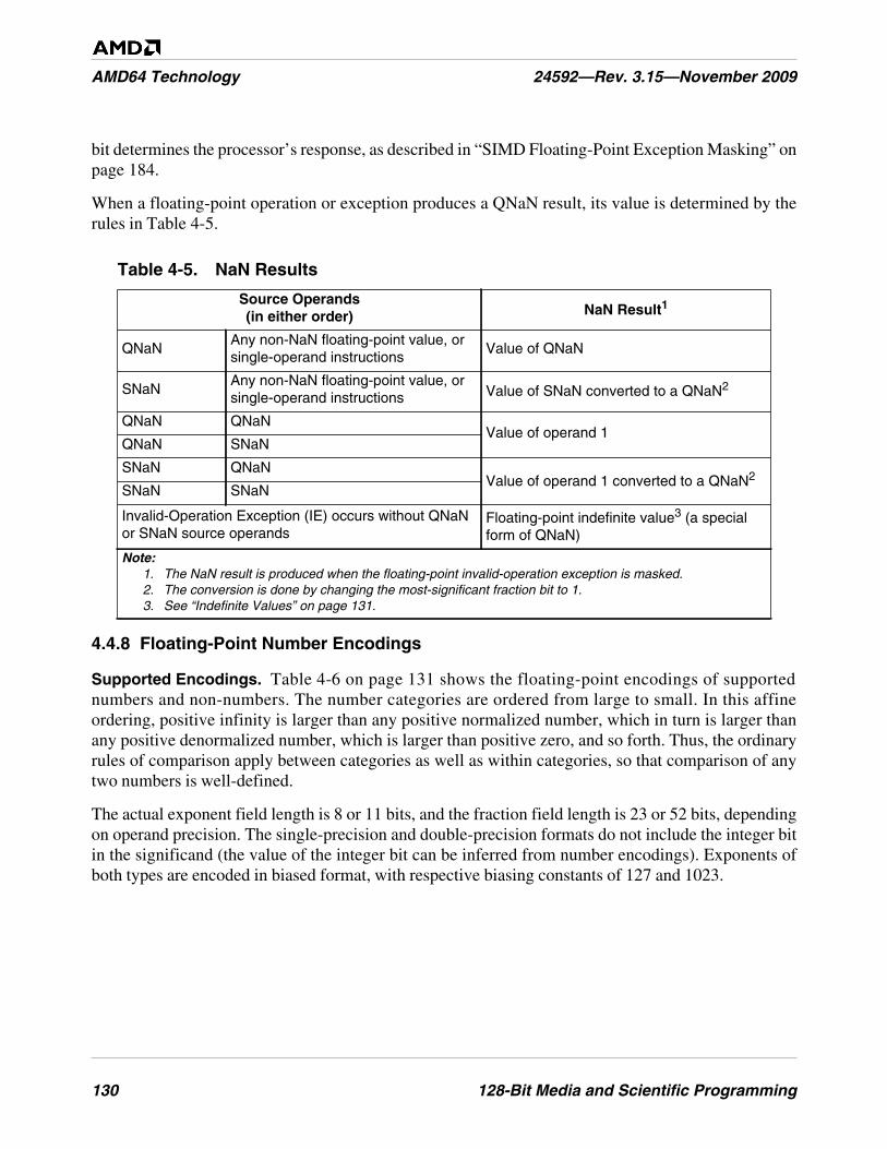
130 128-Bit Media and Scientific Programming
AMD64 Technology 24592—Rev. 3.15—November 2009
bit determines the processor’s response, as described in “SIMD Floating-Point Exception Masking” onpage 184.
When a floating-point operation or exception produces a QNaN result, its value is determined by therules in Table 4-5.
4.4.8 Floating-Point Number Encodings
Supported Encodings. Table 4-6 on page 131 shows the floating-point encodings of supportednumbers and non-numbers. The number categories are ordered from large to small. In this affineordering, positive infinity is larger than any positive normalized number, which in turn is larger thanany positive denormalized number, which is larger than positive zero, and so forth. Thus, the ordinaryrules of comparison apply between categories as well as within categories, so that comparison of anytwo numbers is well-defined.
The actual exponent field length is 8 or 11 bits, and the fraction field length is 23 or 52 bits, dependingon operand precision. The single-precision and double-precision formats do not include the integer bitin the significand (the value of the integer bit can be inferred from number encodings). Exponents ofboth types are encoded in biased format, with respective biasing constants of 127 and 1023.
Table 4-5. NaN Results
Source Operands(in either order) NaN Result1
QNaNAny non-NaN floating-point value, orsingle-operand instructions
Value of QNaN
SNaNAny non-NaN floating-point value, orsingle-operand instructions Value of SNaN converted to a QNaN2
QNaN QNaNValue of operand 1
QNaN SNaN
SNaN QNaNValue of operand 1 converted to a QNaN2
SNaN SNaN
Invalid-Operation Exception (IE) occurs without QNaNor SNaN source operands
Floating-point indefinite value3 (a specialform of QNaN)
Note:1. The NaN result is produced when the floating-point invalid-operation exception is masked.2. The conversion is done by changing the most-significant fraction bit to 1.3. See “Indefinite Values” on page 131.
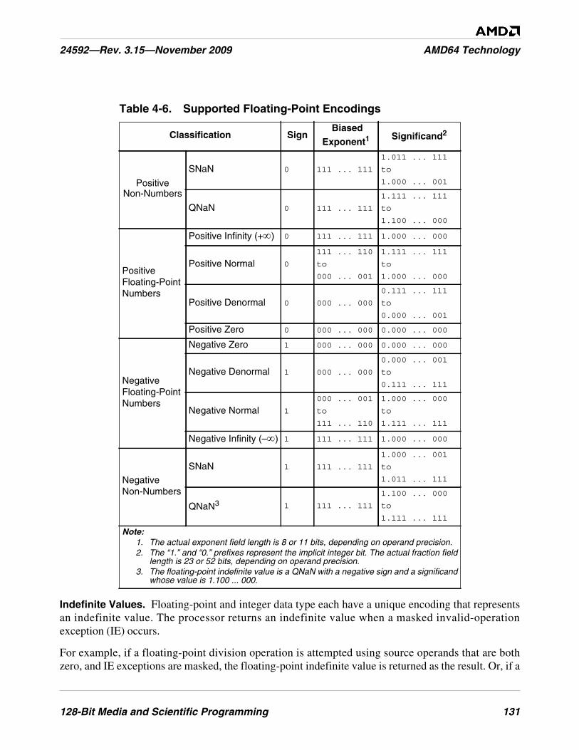
128-Bit Media and Scientific Programming 131
24592—Rev. 3.15—November 2009 AMD64 Technology
Indefinite Values. Floating-point and integer data type each have a unique encoding that representsan indefinite value. The processor returns an indefinite value when a masked invalid-operationexception (IE) occurs.
For example, if a floating-point division operation is attempted using source operands that are bothzero, and IE exceptions are masked, the floating-point indefinite value is returned as the result. Or, if a
Table 4-6. Supported Floating-Point Encodings
Classification SignBiased
Exponent1Significand2
PositiveNon-Numbers
SNaN 0 111 ... 111
1.011 ... 111
to
1.000 ... 001
QNaN 0 111 ... 111
1.111 ... 111
to
1.100 ... 000
PositiveFloating-PointNumbers
Positive Infinity (+∞) 0 111 ... 111 1.000 ... 000
Positive Normal 0
111 ... 110
to
000 ... 001
1.111 ... 111
to
1.000 ... 000
Positive Denormal 0 000 ... 000
0.111 ... 111
to
0.000 ... 001
Positive Zero 0 000 ... 000 0.000 ... 000
NegativeFloating-PointNumbers
Negative Zero 1 000 ... 000 0.000 ... 000
Negative Denormal 1 000 ... 000
0.000 ... 001
to
0.111 ... 111
Negative Normal 1
000 ... 001
to
111 ... 110
1.000 ... 000
to
1.111 ... 111
Negative Infinity (–∞) 1 111 ... 111 1.000 ... 000
NegativeNon-Numbers
SNaN 1 111 ... 111
1.000 ... 001
to
1.011 ... 111
QNaN3 1 111 ... 111
1.100 ... 000
to
1.111 ... 111
Note:1. The actual exponent field length is 8 or 11 bits, depending on operand precision.2. The “1.” and “0.” prefixes represent the implicit integer bit. The actual fraction field
length is 23 or 52 bits, depending on operand precision.3. The floating-point indefinite value is a QNaN with a negative sign and a significand
whose value is 1.100 ... 000.
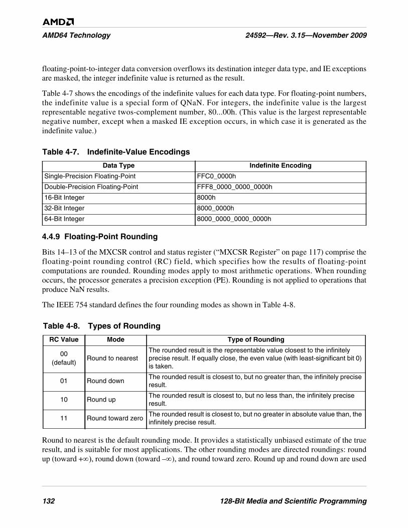
132 128-Bit Media and Scientific Programming
AMD64 Technology 24592—Rev. 3.15—November 2009
floating-point-to-integer data conversion overflows its destination integer data type, and IE exceptionsare masked, the integer indefinite value is returned as the result.
Table 4-7 shows the encodings of the indefinite values for each data type. For floating-point numbers,the indefinite value is a special form of QNaN. For integers, the indefinite value is the largestrepresentable negative twos-complement number, 80...00h. (This value is the largest representablenegative number, except when a masked IE exception occurs, in which case it is generated as theindefinite value.)
4.4.9 Floating-Point Rounding
Bits 14–13 of the MXCSR control and status register (“MXCSR Register” on page 117) comprise thefloating-point rounding control (RC) field, which specifies how the results of floating-pointcomputations are rounded. Rounding modes apply to most arithmetic operations. When roundingoccurs, the processor generates a precision exception (PE). Rounding is not applied to operations thatproduce NaN results.
The IEEE 754 standard defines the four rounding modes as shown in Table 4-8.
Round to nearest is the default rounding mode. It provides a statistically unbiased estimate of the trueresult, and is suitable for most applications. The other rounding modes are directed roundings: roundup (toward +∞), round down (toward –∞), and round toward zero. Round up and round down are used
Table 4-7. Indefinite-Value Encodings
Data Type Indefinite Encoding
Single-Precision Floating-Point FFC0_0000h
Double-Precision Floating-Point FFF8_0000_0000_0000h
16-Bit Integer 8000h
32-Bit Integer 8000_0000h
64-Bit Integer 8000_0000_0000_0000h
Table 4-8. Types of Rounding
RC Value Mode Type of Rounding
00(default)
Round to nearestThe rounded result is the representable value closest to the infinitelyprecise result. If equally close, the even value (with least-significant bit 0)is taken.
01 Round downThe rounded result is closest to, but no greater than, the infinitely preciseresult.
10 Round upThe rounded result is closest to, but no less than, the infinitely preciseresult.
11 Round toward zeroThe rounded result is closest to, but no greater in absolute value than, theinfinitely precise result.
128-Bit Media and Scientific Programming 133
24592—Rev. 3.15—November 2009 AMD64 Technology
in interval arithmetic, in which upper and lower bounds bracket the true result of a computation.Round toward zero takes the smaller in magnitude, that is, always truncates.
The processor produces a floating-point result defined by the IEEE standard to be infinitely precise.This result may not be representable exactly in the destination format, because only a subset of thecontinuum of real numbers finds exact representation in any particular floating-point format.Rounding modifies such a result to conform to the destination format, thereby making the resultinexact and also generating a precision exception (PE), as described in “SIMD Floating-PointException Causes” on page 178.
Suppose, for example, the following 24-bit result is to be represented in single-precision format, where“E2 1010” represents the biased exponent:
1.0011 0101 0000 0001 0010 0111 E2 1010
This result has no exact representation, because the least-significant 1 does not fit into the single-precision format, which allows for only 23 bits of fraction. The rounding control field determines thedirection of rounding. Rounding introduces an error in a result that is less than one unit in the last place(ulp), that is, the least-significant bit position of the floating-point representation.
4.5 Instruction Summary—Integer Instructions
This section summarizes functions of the integer instructions in the 128-bit media instruction subset.These include integer instructions that use an XMM register for source or destination and data-conversion instructions that convert from integers to floating-point formats. For a summary of thefloating-point instructions in the 128-bit media instruction subset, including data-conversioninstructions that convert from floating-point to integer formats, see “Instruction Summary—Floating-Point Instructions” on page 156.
The instructions are organized here by functional group—such as data-transfer, vector arithmetic, andso on. Software running at any privilege level can use any of these instructions, if the CPUIDinstruction reports support for the instructions (see “Feature Detection” on page 176). More detail onindividual instructions is given in the alphabetically organized “128-Bit Media Instruction Reference”in Volume 4.
4.5.1 Syntax
Each instruction has a mnemonic syntax used by assemblers to specify the operation and the operandsto be used for source and destination (result) data. The majority of 128-bit media integer instructionshave the following syntax:
MNEMONIC xmm1, xmm2/mem128
Figure 4-16 on page 134 shows an example of the mnemonic syntax for a packed add bytes (PADDB)instruction.
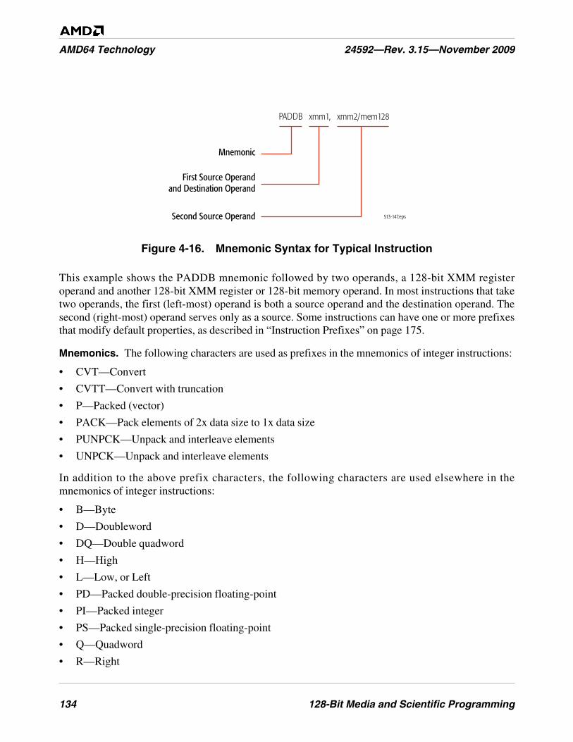
134 128-Bit Media and Scientific Programming
AMD64 Technology 24592—Rev. 3.15—November 2009
Figure 4-16. Mnemonic Syntax for Typical Instruction
This example shows the PADDB mnemonic followed by two operands, a 128-bit XMM registeroperand and another 128-bit XMM register or 128-bit memory operand. In most instructions that taketwo operands, the first (left-most) operand is both a source operand and the destination operand. Thesecond (right-most) operand serves only as a source. Some instructions can have one or more prefixesthat modify default properties, as described in “Instruction Prefixes” on page 175.
Mnemonics. The following characters are used as prefixes in the mnemonics of integer instructions:
• CVT—Convert
• CVTT—Convert with truncation
• P—Packed (vector)
• PACK—Pack elements of 2x data size to 1x data size
• PUNPCK—Unpack and interleave elements
• UNPCK—Unpack and interleave elements
In addition to the above prefix characters, the following characters are used elsewhere in themnemonics of integer instructions:
• B—Byte
• D—Doubleword
• DQ—Double quadword
• H—High
• L—Low, or Left
• PD—Packed double-precision floating-point
• PI—Packed integer
• PS—Packed single-precision floating-point
• Q—Quadword
• R—Right
513-147.eps
Mnemonic
First Source Operandand Destination Operand
Second Source Operand
PADDB xmm1, xmm2/mem128
128-Bit Media and Scientific Programming 135
24592—Rev. 3.15—November 2009 AMD64 Technology
• S—Signed, or Saturation, or Shift
• SD—Scalar double-precision floating-point
• SI—Signed integer
• SS—Scalar single-precision floating-point, or Signed saturation
• U—Unsigned, or Unordered, or Unaligned
• US—Unsigned saturation
• W—Word
• x—One or more variable characters in the mnemonic
For example, the mnemonic for the instruction that packs four words into eight unsigned bytes isPACKUSWB. In this mnemonic, the US designates an unsigned result with saturation, and the WBdesignates the source as words and the result as bytes.
4.5.2 Data Transfer
The data-transfer instructions copy operands between a memory location, an XMM register, an MMXregister, or a GPR. The MOV mnemonic, which stands for move, is a misnomer. A copy function isactually performed instead of a move. A new copy of the source value is created at the destinationaddress, and the original copy remains unchanged at its source location.
Move.
• MOVD—Move Doubleword or Quadword
• MOVQ—Move Quadword
• MOVDQA—Move Aligned Double Quadword
• MOVDQU—Move Unaligned Double Quadword
• MOVDQ2Q—Move Quadword to Quadword
• MOVQ2DQ—Move Quadword to Quadword
• LDDQU—Load Double Quadword Unaligned
The MOVD instruction copies a 32-bit or 64-bit value from a GPR register or memory location to thelow-order 32 or 64 bits of an XMM register, or from the low-order 32 or 64 bits of an XMM register toa 32-bit or 64-bit GPR or memory location. If the source operand is a GPR or memory location, thesource is zero-extended to 128 bits in the XMM register. If the source is an XMM register, only thelow-order 32 or 64 bits of the source are copied to the destination.
The MOVQ instruction copies a 64-bit value from memory to the low quadword of an XMM register,or from the low quadword of an XMM register to memory, or between the low quadwords of twoXMM registers. If the source is in memory and the destination is an XMM register, the source is zero-extended to 128 bits in the XMM register.
The MOVDQA instruction copies a 128-bit value from memory to an XMM register, or from an XMMregister to memory, or between two XMM registers. If either the source or destination is a memory
136 128-Bit Media and Scientific Programming
AMD64 Technology 24592—Rev. 3.15—November 2009
location, the memory address must be aligned. The MOVDQU instruction does the same, except forunaligned operands. The LDDQU instruction is virtually identical in operation to the MOVDQUinstruction. The LDDQU instruction moves a double quadword of data from a 128-bit memoryoperand into a destination XMM register.
The MOVDQ2Q instruction copies the low-order 64-bit value in an XMM register to an MMXregister. The MOVQ2DQ instruction copies a 64-bit value from an MMX register to the low-order 64bits of an XMM register, with zero-extension to 128 bits.
Figure 4-17 on page 137 shows the capabilities of the various integer move instructions. Theseinstructions move large amounts of data. When copying between XMM registers, or between an XMMregister and memory, a move instruction can copy up to 16 bytes of data. When copying between anXMM register and an MMX or GPR register, a move instruction can copy up to 8 bytes of data. TheMOVx instructions—along with the PUNPCKx instructions—are often among the most frequentlyused instructions in 128-bit media integer and floating-point procedures.
The move instructions are in many respects similar to the assignment operator in high-level languages.The simplest example of their use is for initializing variables. To initialize a register to 0, however,rather than using a MOVx instruction it may be more efficient to use the PXOR instruction withidentical destination and source operands.
Move Non-Temporal. The move non-temporal instructions are streaming-store instructions. Theyminimize pollution of the cache.
• MOVNTDQ—Move Non-Temporal Double Quadword
• MASKMOVDQU—Masked Move Double Quadword Unaligned
The MOVNTDQ instruction stores its second operand (a 128-bit XMM register value) into its firstoperand (a 128-bit memory location). MOVNTDQ indicates to the processor that its data is non-temporal, which assumes that the referenced data will be used only once and is therefore not subject tocache-related overhead (as opposed to temporal data, which assumes that the data will be accessedagain soon and should be cached). The non-temporal instructions use weakly-ordered, write-combining buffering of write data, and they minimize cache pollution. The exact method by whichcache pollution is minimized depends on the hardware implementation of the instruction. For furtherinformation, see “Memory Optimization” on page 92.
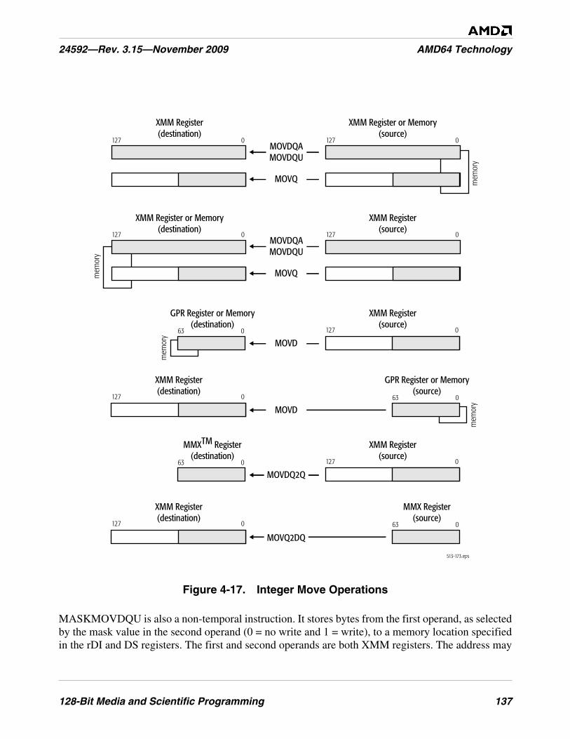
128-Bit Media and Scientific Programming 137
24592—Rev. 3.15—November 2009 AMD64 Technology
Figure 4-17. Integer Move Operations
MASKMOVDQU is also a non-temporal instruction. It stores bytes from the first operand, as selectedby the mask value in the second operand (0 = no write and 1 = write), to a memory location specifiedin the rDI and DS registers. The first and second operands are both XMM registers. The address may
mem
ory
513-173.eps
MOVDQAMOVDQU
127 0127 0
MOVQ mem
ory
XMM Register or Memory(source)
XMM Register(destination)
MOVDQAMOVDQU
127 0127 0
MOVQ
MOVD
XMM Register(source)
XMM Register or Memory(destination)
XMM Register(source)
GPR Register or Memory(destination)
127 063 0
mem
ory
MOVD
XMM Register(destination)
GPR Register or Memory(source)
127 0 63 0
mem
ory
XMM Register(source)
MMXTM Register(destination)
127 063 0
XMM Register(destination)
MMX Register(source)
127 0 63 0
MOVDQ2Q
MOVQ2DQ
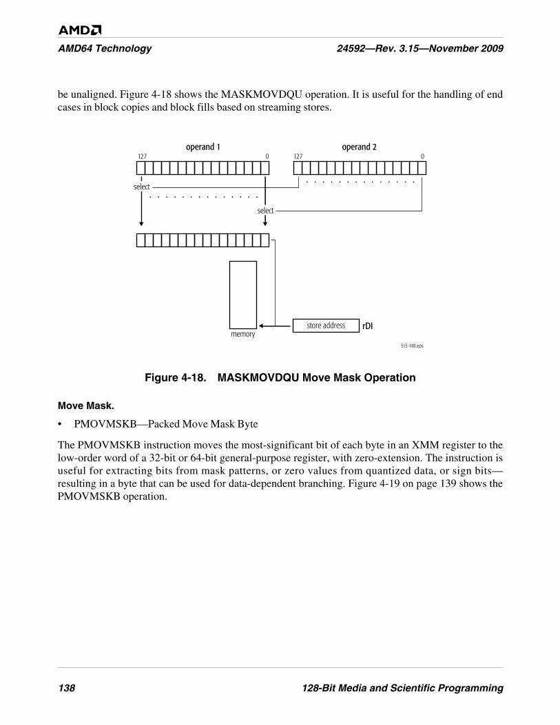
138 128-Bit Media and Scientific Programming
AMD64 Technology 24592—Rev. 3.15—November 2009
be unaligned. Figure 4-18 shows the MASKMOVDQU operation. It is useful for the handling of endcases in block copies and block fills based on streaming stores.
Figure 4-18. MASKMOVDQU Move Mask Operation
Move Mask.
• PMOVMSKB—Packed Move Mask Byte
The PMOVMSKB instruction moves the most-significant bit of each byte in an XMM register to thelow-order word of a 32-bit or 64-bit general-purpose register, with zero-extension. The instruction isuseful for extracting bits from mask patterns, or zero values from quantized data, or sign bits—resulting in a byte that can be used for data-dependent branching. Figure 4-19 on page 139 shows thePMOVMSKB operation.
operand 1
. . . . . . . . . . . . . .
. . . . . . . . . . . . . .
127 0operand 2
127 0
select
select
store addressmemory
rDI
513-148.eps
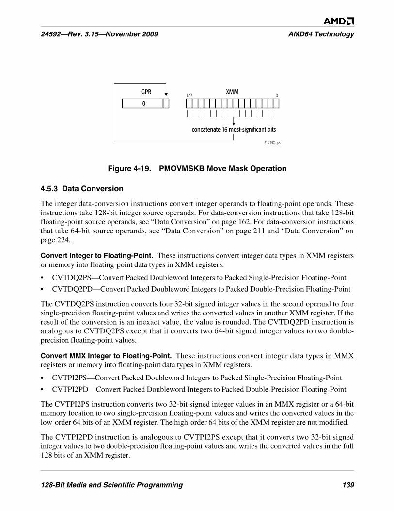
128-Bit Media and Scientific Programming 139
24592—Rev. 3.15—November 2009 AMD64 Technology
Figure 4-19. PMOVMSKB Move Mask Operation
4.5.3 Data Conversion
The integer data-conversion instructions convert integer operands to floating-point operands. Theseinstructions take 128-bit integer source operands. For data-conversion instructions that take 128-bitfloating-point source operands, see “Data Conversion” on page 162. For data-conversion instructionsthat take 64-bit source operands, see “Data Conversion” on page 211 and “Data Conversion” onpage 224.
Convert Integer to Floating-Point. These instructions convert integer data types in XMM registersor memory into floating-point data types in XMM registers.
• CVTDQ2PS—Convert Packed Doubleword Integers to Packed Single-Precision Floating-Point
• CVTDQ2PD—Convert Packed Doubleword Integers to Packed Double-Precision Floating-Point
The CVTDQ2PS instruction converts four 32-bit signed integer values in the second operand to foursingle-precision floating-point values and writes the converted values in another XMM register. If theresult of the conversion is an inexact value, the value is rounded. The CVTDQ2PD instruction isanalogous to CVTDQ2PS except that it converts two 64-bit signed integer values to two double-precision floating-point values.
Convert MMX Integer to Floating-Point. These instructions convert integer data types in MMXregisters or memory into floating-point data types in XMM registers.
• CVTPI2PS—Convert Packed Doubleword Integers to Packed Single-Precision Floating-Point
• CVTPI2PD—Convert Packed Doubleword Integers to Packed Double-Precision Floating-Point
The CVTPI2PS instruction converts two 32-bit signed integer values in an MMX register or a 64-bitmemory location to two single-precision floating-point values and writes the converted values in thelow-order 64 bits of an XMM register. The high-order 64 bits of the XMM register are not modified.
The CVTPI2PD instruction is analogous to CVTPI2PS except that it converts two 32-bit signedinteger values to two double-precision floating-point values and writes the converted values in the full128 bits of an XMM register.
513-157..eps
GPR XMM127 0
concatenate 16 most-significant bits
0
140 128-Bit Media and Scientific Programming
AMD64 Technology 24592—Rev. 3.15—November 2009
Before executing a CVTPI2x instruction, software should ensure that the MMX registers are properlyinitialized so as to prevent conflict with their aliased use by x87 floating-point instructions. This mayrequire clearing the MMX state, as described in “Accessing Operands in MMX™ Registers” onpage 188.
For a description of 128-bit media instructions that convert in the opposite direction—floating-point tointeger in MMX registers—see “Convert Floating-Point to MMX™ Integer” on page 163. For asummary of instructions that operate on MMX registers, see Chapter 5, “64-Bit Media Programming.”
Convert GPR Integer to Floating-Point. These instructions convert integer data types in GPRregisters or memory into floating-point data types in XMM registers.
• CVTSI2SS—Convert Signed Doubleword or Quadword Integer to Scalar Single-PrecisionFloating-Point
• CVTSI2SD—Convert Signed Doubleword or Quadword Integer to Scalar Double-PrecisionFloating-Point
The CVTSI2SS instruction converts a 32-bit or 64-bit signed integer value in a general-purposeregister or memory location to a single-precision floating-point value and writes the converted value inthe low-order 32 bits of an XMM register. The three high-order doublewords in the destination XMMregister are not modified.
The CVTSI2SD instruction converts a 32-bit or 64-bit signed integer value in a general-purposeregister or memory location to a double-precision floating-point value and writes the converted valuein the low-order 64 bits of an XMM register. The high-order 64 bits in the destination XMM registerare not modified.
4.5.4 Data Reordering
The integer data-reordering instructions pack, unpack, interleave, extract, insert, and shuffle theelements of vector operands.
Pack with Saturation. These instructions pack larger data types into smaller data types, thus halvingthe precision of each element in a vector operand.
• PACKSSDW—Pack with Saturation Signed Doubleword to Word
• PACKSSWB—Pack with Saturation Signed Word to Byte
• PACKUSWB—Pack with Saturation Signed Word to Unsigned Byte
The PACKSSDW instruction converts each of the four signed doubleword integers in its two sourceoperands (an XMM register, and another XMM register or 128-bit memory location) into signed wordintegers and packs the converted values into the destination operand (an XMM register). ThePACKSSWB instruction does the analogous conversion between word elements in the source vectorsand byte elements in the destination vector. The PACKUSWB instruction does the same asPACKSSWB except that it converts signed word integers into unsigned (rather than signed) bytes.
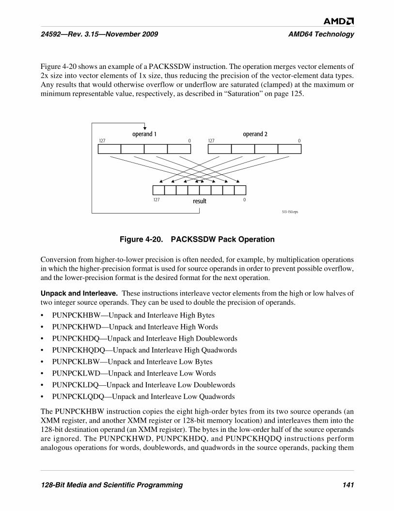
128-Bit Media and Scientific Programming 141
24592—Rev. 3.15—November 2009 AMD64 Technology
Figure 4-20 shows an example of a PACKSSDW instruction. The operation merges vector elements of2x size into vector elements of 1x size, thus reducing the precision of the vector-element data types.Any results that would otherwise overflow or underflow are saturated (clamped) at the maximum orminimum representable value, respectively, as described in “Saturation” on page 125.
Figure 4-20. PACKSSDW Pack Operation
Conversion from higher-to-lower precision is often needed, for example, by multiplication operationsin which the higher-precision format is used for source operands in order to prevent possible overflow,and the lower-precision format is the desired format for the next operation.
Unpack and Interleave. These instructions interleave vector elements from the high or low halves oftwo integer source operands. They can be used to double the precision of operands.
• PUNPCKHBW—Unpack and Interleave High Bytes
• PUNPCKHWD—Unpack and Interleave High Words
• PUNPCKHDQ—Unpack and Interleave High Doublewords
• PUNPCKHQDQ—Unpack and Interleave High Quadwords
• PUNPCKLBW—Unpack and Interleave Low Bytes
• PUNPCKLWD—Unpack and Interleave Low Words
• PUNPCKLDQ—Unpack and Interleave Low Doublewords
• PUNPCKLQDQ—Unpack and Interleave Low Quadwords
The PUNPCKHBW instruction copies the eight high-order bytes from its two source operands (anXMM register, and another XMM register or 128-bit memory location) and interleaves them into the128-bit destination operand (an XMM register). The bytes in the low-order half of the source operandsare ignored. The PUNPCKHWD, PUNPCKHDQ, and PUNPCKHQDQ instructions performanalogous operations for words, doublewords, and quadwords in the source operands, packing them
513-150.eps
operand 1
result
127 0
127 0
operand 2127 0
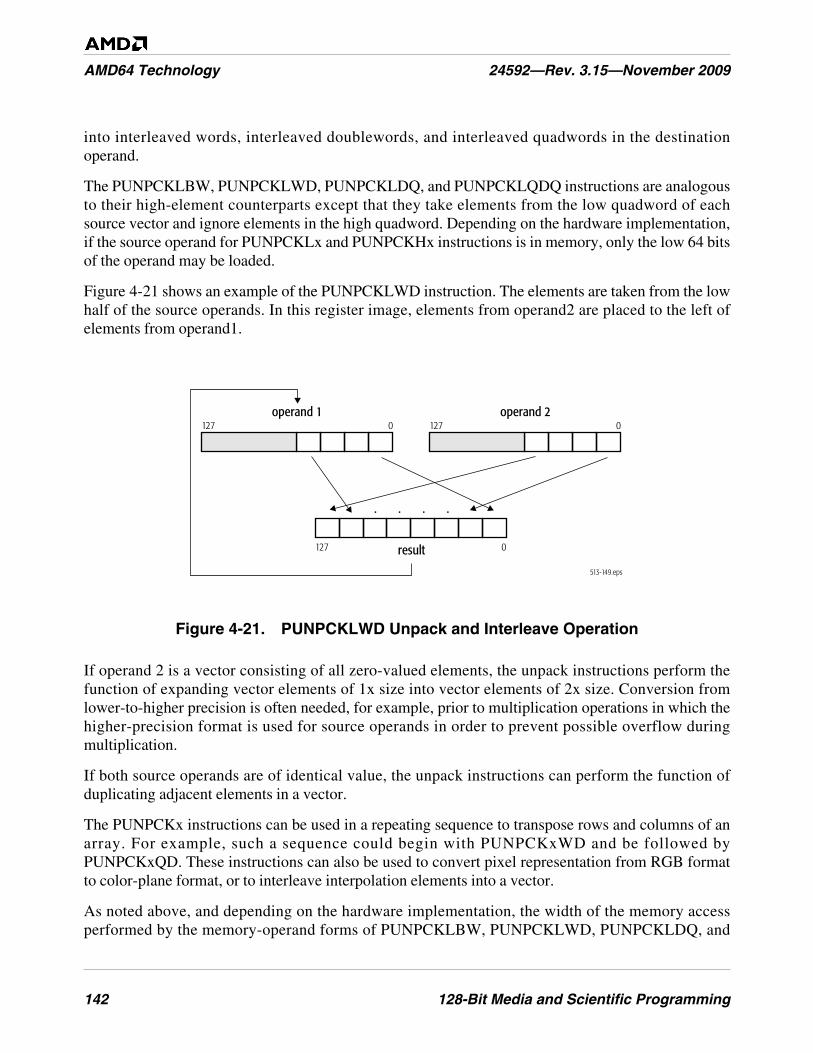
142 128-Bit Media and Scientific Programming
AMD64 Technology 24592—Rev. 3.15—November 2009
into interleaved words, interleaved doublewords, and interleaved quadwords in the destinationoperand.
The PUNPCKLBW, PUNPCKLWD, PUNPCKLDQ, and PUNPCKLQDQ instructions are analogousto their high-element counterparts except that they take elements from the low quadword of eachsource vector and ignore elements in the high quadword. Depending on the hardware implementation,if the source operand for PUNPCKLx and PUNPCKHx instructions is in memory, only the low 64 bitsof the operand may be loaded.
Figure 4-21 shows an example of the PUNPCKLWD instruction. The elements are taken from the lowhalf of the source operands. In this register image, elements from operand2 are placed to the left ofelements from operand1.
Figure 4-21. PUNPCKLWD Unpack and Interleave Operation
If operand 2 is a vector consisting of all zero-valued elements, the unpack instructions perform thefunction of expanding vector elements of 1x size into vector elements of 2x size. Conversion fromlower-to-higher precision is often needed, for example, prior to multiplication operations in which thehigher-precision format is used for source operands in order to prevent possible overflow duringmultiplication.
If both source operands are of identical value, the unpack instructions can perform the function ofduplicating adjacent elements in a vector.
The PUNPCKx instructions can be used in a repeating sequence to transpose rows and columns of anarray. For example, such a sequence could begin with PUNPCKxWD and be followed byPUNPCKxQD. These instructions can also be used to convert pixel representation from RGB formatto color-plane format, or to interleave interpolation elements into a vector.
As noted above, and depending on the hardware implementation, the width of the memory accessperformed by the memory-operand forms of PUNPCKLBW, PUNPCKLWD, PUNPCKLDQ, and
513-149.eps
operand 1
result
127 0operand 2
127 0
127 0
. .. .
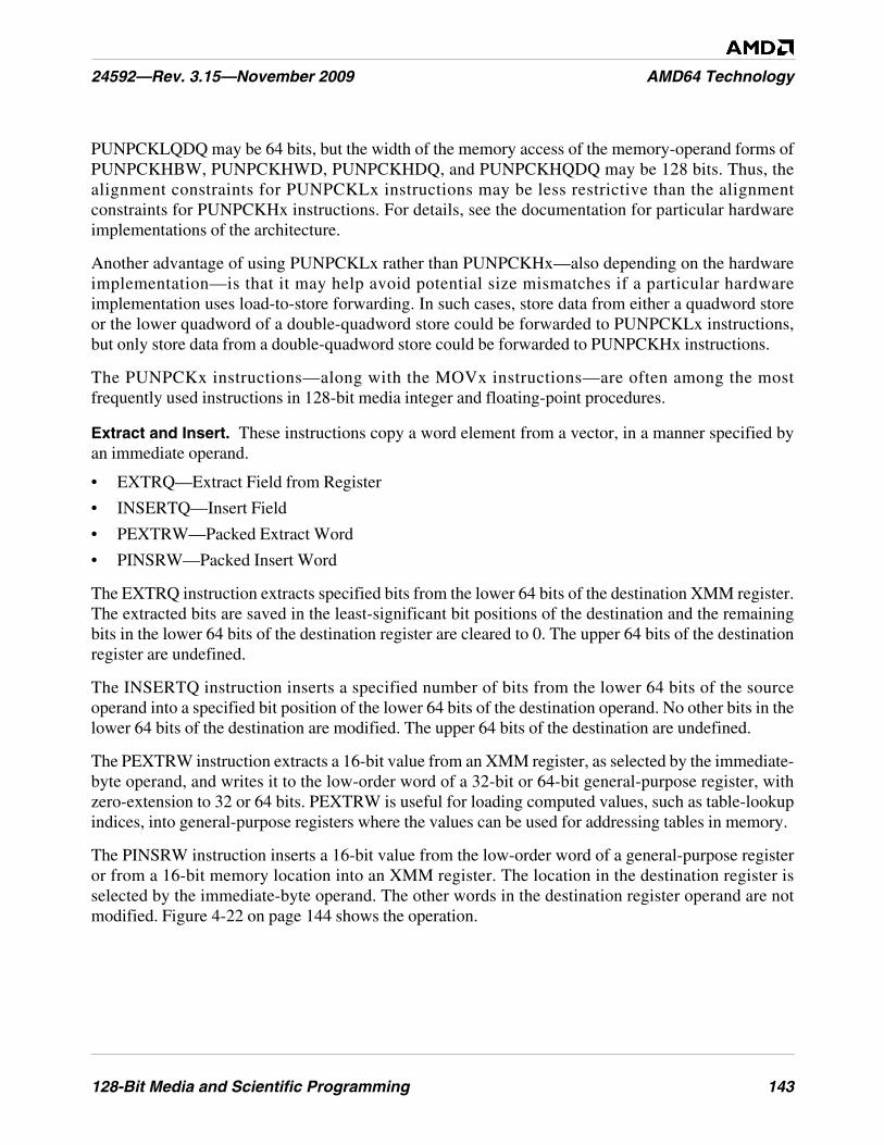
128-Bit Media and Scientific Programming 143
24592—Rev. 3.15—November 2009 AMD64 Technology
PUNPCKLQDQ may be 64 bits, but the width of the memory access of the memory-operand forms ofPUNPCKHBW, PUNPCKHWD, PUNPCKHDQ, and PUNPCKHQDQ may be 128 bits. Thus, thealignment constraints for PUNPCKLx instructions may be less restrictive than the alignmentconstraints for PUNPCKHx instructions. For details, see the documentation for particular hardwareimplementations of the architecture.
Another advantage of using PUNPCKLx rather than PUNPCKHx—also depending on the hardwareimplementation—is that it may help avoid potential size mismatches if a particular hardwareimplementation uses load-to-store forwarding. In such cases, store data from either a quadword storeor the lower quadword of a double-quadword store could be forwarded to PUNPCKLx instructions,but only store data from a double-quadword store could be forwarded to PUNPCKHx instructions.
The PUNPCKx instructions—along with the MOVx instructions—are often among the mostfrequently used instructions in 128-bit media integer and floating-point procedures.
Extract and Insert. These instructions copy a word element from a vector, in a manner specified byan immediate operand.
• EXTRQ—Extract Field from Register
• INSERTQ—Insert Field
• PEXTRW—Packed Extract Word
• PINSRW—Packed Insert Word
The EXTRQ instruction extracts specified bits from the lower 64 bits of the destination XMM register.The extracted bits are saved in the least-significant bit positions of the destination and the remainingbits in the lower 64 bits of the destination register are cleared to 0. The upper 64 bits of the destinationregister are undefined.
The INSERTQ instruction inserts a specified number of bits from the lower 64 bits of the sourceoperand into a specified bit position of the lower 64 bits of the destination operand. No other bits in thelower 64 bits of the destination are modified. The upper 64 bits of the destination are undefined.
The PEXTRW instruction extracts a 16-bit value from an XMM register, as selected by the immediate-byte operand, and writes it to the low-order word of a 32-bit or 64-bit general-purpose register, withzero-extension to 32 or 64 bits. PEXTRW is useful for loading computed values, such as table-lookupindices, into general-purpose registers where the values can be used for addressing tables in memory.
The PINSRW instruction inserts a 16-bit value from the low-order word of a general-purpose registeror from a 16-bit memory location into an XMM register. The location in the destination register isselected by the immediate-byte operand. The other words in the destination register operand are notmodified. Figure 4-22 on page 144 shows the operation.

144 128-Bit Media and Scientific Programming
AMD64 Technology 24592—Rev. 3.15—November 2009
Figure 4-22. PINSRW Operation
Shuffle. These instructions reorder the elements of a vector.
• PSHUFD—Packed Shuffle Doublewords
• PSHUFHW—Packed Shuffle High Words
• PSHUFLW—Packed Shuffle Low Words
The PSHUFD instruction fills each doubleword of the first operand (an XMM register) by copying anyone of the doublewords in the second operand (an XMM register or 128-bit memory location). Theordering of the shuffle can occur in one of 256 possible ways, as specified by the third operand, animmediate byte. Figure 4-23 on page 145 shows one of the 256 possible shuffle operations.
513-166.eps
xmm
result
127 0reg32/64/mem16
127 0
15 0
select word position for insert
imm8

128-Bit Media and Scientific Programming 145
24592—Rev. 3.15—November 2009 AMD64 Technology
Figure 4-23. PSHUFD Shuffle Operation
The PSHUFHW and PSHUFLW instructions are analogous to PSHUFD, except that they fill eachword of the high or low quadword, respectively, of the first operand by copying any one of the fourwords in the high or low quadword of the second operand. Figure 4-24 shows the PSHUFHWoperation. PSHUFHW and PSHUFLW are useful, for example, in color imaging when computingalpha saturation of RGB values. In this case, PSHUFxW can replicate an alpha value in a register sothat parallel comparisons with three RGB values can be performed.
Figure 4-24. PSHUFHW Shuffle Operation
4.5.5 Arithmetic
The integer vector-arithmetic instructions perform an arithmetic operation on the elements of twosource vectors. Figure 4-25 on page 146 shows a typical arithmetic operation on vectors of bytes. Suchinstructions performs 16 arithmetic operations in parallel.
513-151.eps
result
operand 1127 0
127 0
operand 2127 0
513-167.eps
result
operand 1127 0
127 0
operand 2127 0
146 128-Bit Media and Scientific Programming
AMD64 Technology 24592—Rev. 3.15—November 2009
Figure 4-25. Arithmetic Operation on Vectors of Bytes
Addition.
• PADDB—Packed Add Bytes
• PADDW—Packed Add Words
• PADDD—Packed Add Doublewords
• PADDQ—Packed Add Quadwords
• PADDSB—Packed Add with Saturation Bytes
• PADDSW—Packed Add with Saturation Words
• PADDUSB—Packed Add Unsigned with Saturation Bytes
• PADDUSW—Packed Add Unsigned with Saturation Words
The PADDB, PADDW, PADDD, and PADDQ instructions add each packed 8-bit (PADDB), 16-bit(PADDW), 32-bit (PADDD), or 64-bit (PADDQ) integer element in the second operand to thecorresponding, same-sized integer element in the first operand and write the integer result to thecorresponding, same-sized element of the destination. Figure 4-25 shows a PADDB operation. Theseinstructions operate on both signed and unsigned integers. However, if the result overflows, the carry isignored and only the low-order byte, word, doubleword, or quadword of each result is written to thedestination. The PADDD instruction can be used together with PMADDWD (page 149) to implementdot products.
The PADDSB and PADDSW instructions add each 8-bit (PADDSB) or 16-bit (PADDSW) signedinteger element in the second operand to the corresponding, same-sized signed integer element in thefirst operand and write the signed integer result to the corresponding, same-sized element of thedestination. For each result in the destination, if the result is larger than the largest, or smaller than thesmallest, representable 8-bit (PADDSB) or 16-bit (PADDSW) signed integer, the result is saturated tothe largest or smallest representable value, respectively.
operand 1
. . . . . . . . . . . . . .. . . . . . . . . . . . . .
. . . . . . . . . . . . . .
127 0operand 2
127 0
operationoperation
513-163.epsresult127 0
128-Bit Media and Scientific Programming 147
24592—Rev. 3.15—November 2009 AMD64 Technology
The PADDUSB and PADDUSW instructions perform saturating-add operations analogous to thePADDSB and PADDSW instructions, except on unsigned integer elements.
Subtraction.
• PSUBB—Packed Subtract Bytes
• PSUBW—Packed Subtract Words
• PSUBD—Packed Subtract Doublewords
• PSUBQ—Packed Subtract Quadword
• PSUBSB—Packed Subtract with Saturation Bytes
• PSUBSW—Packed Subtract with Saturation Words
• PSUBUSB—Packed Subtract Unsigned and Saturate Bytes
• PSUBUSW—Packed Subtract Unsigned and Saturate Words
The subtraction instructions perform operations analogous to the addition instructions.
The PSUBB, PSUBW, PSUBD, and PSUBQ instructions subtract each 8-bit (PSUBB), 16-bit(PSUBW), 32-bit (PSUBD), or 64-bit (PSUBQ) integer element in the second operand from thecorresponding, same-sized integer element in the first operand and write the integer result to thecorresponding, same-sized element of the destination. For vectors of n number of elements, theoperation is:
operand1[i] = operand1[i] - operand2[i]
where: i = 0 to n – 1
These instructions operate on both signed and unsigned integers. However, if the result underflows, theborrow is ignored and only the low-order byte, word, doubleword, or quadword of each result iswritten to the destination.
The PSUBSB and PSUBSW instructions subtract each 8-bit (PSUBSB) or 16-bit (PSUBSW) signedinteger element in the second operand from the corresponding, same-sized signed integer element inthe first operand and write the signed integer result to the corresponding, same-sized element of thedestination. For each result in the destination, if the result is larger than the largest, or smaller than thesmallest, representable 8-bit (PSUBSB) or 16-bit (PSUBSW) signed integer, the result is saturated tothe largest or smallest representable value, respectively.
The PSUBUSB and PSUBUSW instructions perform saturating-add operations analogous to thePSUBSB and PSUBSW instructions, except on unsigned integer elements.
Multiplication.
• PMULHW—Packed Multiply High Signed Word
• PMULLW—Packed Multiply Low Signed Word
• PMULHUW—Packed Multiply High Unsigned Word
• PMULUDQ—Packed Multiply Unsigned Doubleword and Store Quadword

148 128-Bit Media and Scientific Programming
AMD64 Technology 24592—Rev. 3.15—November 2009
The PMULHW instruction multiplies each 16-bit signed integer value in the first operand by thecorresponding 16-bit integer in the second operand, producing a 32-bit intermediate result. Theinstruction then writes the high-order 16 bits of the 32-bit intermediate result of each multiplication tothe corresponding word of the destination. The PMULLW instruction performs the samemultiplication as PMULHW but writes the low-order 16 bits of the 32-bit intermediate result to thecorresponding word of the destination.
Figure 4-26 shows the PMULHW and PMULLW operations. The difference between the two iswhether the high or low half of each intermediate-element result is copied to the destination result.
Figure 4-26. PMULxW Multiply Operation
The PMULHUW instruction performs the same multiplication as PMULHW but on unsignedoperands. Without this instruction, it is difficult to perform unsigned integer multiplies using 128-bitmedia instructions. The instruction is useful in 3D rasterization, which operates on unsigned pixelvalues.
The PMULUDQ instruction, unlike the other PMULx instructions, preserves the full precision ofresults by multiplying only half of the source-vector elements. It multiplies the 32-bit unsigned integervalues in the first (low-order) and third doublewords of the source operands, writes the full 64-bitresult of the low-order multiply to the low-order doubleword of the destination, and writes acorresponding result of the high-order multiply to the high-order doubleword of the destination.Figure 4-27 on page 149 shows a PMULUDQ operation.
513-152.eps
operand 1
result
127 0operand 2
127 0
127 0
intermediate result
255 0
* ***
. . . .
. . . .
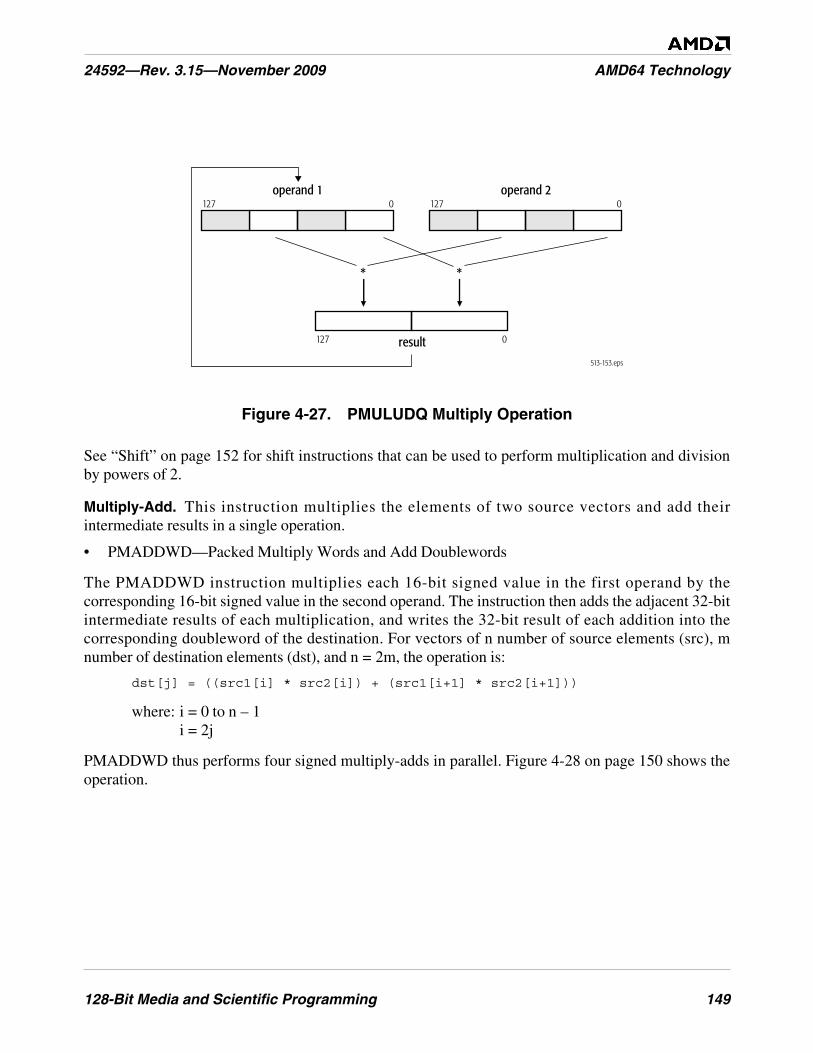
128-Bit Media and Scientific Programming 149
24592—Rev. 3.15—November 2009 AMD64 Technology
Figure 4-27. PMULUDQ Multiply Operation
See “Shift” on page 152 for shift instructions that can be used to perform multiplication and divisionby powers of 2.
Multiply-Add. This instruction multiplies the elements of two source vectors and add theirintermediate results in a single operation.
• PMADDWD—Packed Multiply Words and Add Doublewords
The PMADDWD instruction multiplies each 16-bit signed value in the first operand by thecorresponding 16-bit signed value in the second operand. The instruction then adds the adjacent 32-bitintermediate results of each multiplication, and writes the 32-bit result of each addition into thecorresponding doubleword of the destination. For vectors of n number of source elements (src), mnumber of destination elements (dst), and n = 2m, the operation is:
dst[j] = ((src1[i] * src2[i]) + (src1[i+1] * src2[i+1]))
where: i = 0 to n – 1i = 2j
PMADDWD thus performs four signed multiply-adds in parallel. Figure 4-28 on page 150 shows theoperation.
513-153.eps
operand 1
result
127 0operand 2
127 0
127 0
**
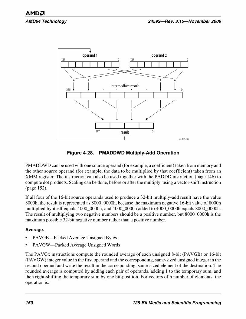
150 128-Bit Media and Scientific Programming
AMD64 Technology 24592—Rev. 3.15—November 2009
Figure 4-28. PMADDWD Multiply-Add Operation
PMADDWD can be used with one source operand (for example, a coefficient) taken from memory andthe other source operand (for example, the data to be multiplied by that coefficient) taken from anXMM register. The instruction can also be used together with the PADDD instruction (page 146) tocompute dot products. Scaling can be done, before or after the multiply, using a vector-shift instruction(page 152).
If all four of the 16-bit source operands used to produce a 32-bit multiply-add result have the value8000h, the result is represented as 8000_0000h, because the maximum negative 16-bit value of 8000hmultiplied by itself equals 4000_0000h, and 4000_0000h added to 4000_0000h equals 8000_0000h.The result of multiplying two negative numbers should be a positive number, but 8000_0000h is themaximum possible 32-bit negative number rather than a positive number.
Average.
• PAVGB—Packed Average Unsigned Bytes
• PAVGW—Packed Average Unsigned Words
The PAVGx instructions compute the rounded average of each unsigned 8-bit (PAVGB) or 16-bit(PAVGW) integer value in the first operand and the corresponding, same-sized unsigned integer in thesecond operand and write the result in the corresponding, same-sized element of the destination. Therounded average is computed by adding each pair of operands, adding 1 to the temporary sum, andthen right-shifting the temporary sum by one bit-position. For vectors of n number of elements, theoperation is:
513-154.eps
operand 1
result
127 0operand 2
127 0
127 0
intermediate result255 0
* ***
. . . .
+ ++ +
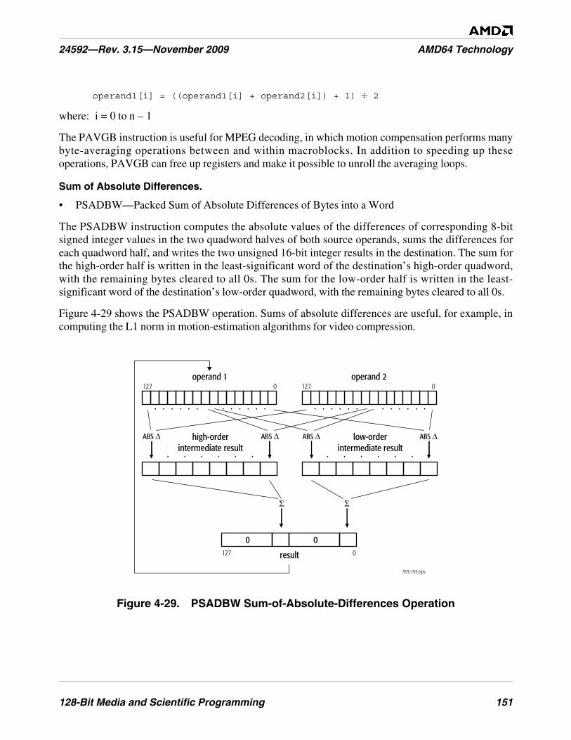
128-Bit Media and Scientific Programming 151
24592—Rev. 3.15—November 2009 AMD64 Technology
operand1[i] = ((operand1[i] + operand2[i]) + 1) ÷ 2
where: i = 0 to n – 1
The PAVGB instruction is useful for MPEG decoding, in which motion compensation performs manybyte-averaging operations between and within macroblocks. In addition to speeding up theseoperations, PAVGB can free up registers and make it possible to unroll the averaging loops.
Sum of Absolute Differences.
• PSADBW—Packed Sum of Absolute Differences of Bytes into a Word
The PSADBW instruction computes the absolute values of the differences of corresponding 8-bitsigned integer values in the two quadword halves of both source operands, sums the differences foreach quadword half, and writes the two unsigned 16-bit integer results in the destination. The sum forthe high-order half is written in the least-significant word of the destination’s high-order quadword,with the remaining bytes cleared to all 0s. The sum for the low-order half is written in the least-significant word of the destination’s low-order quadword, with the remaining bytes cleared to all 0s.
Figure 4-29 shows the PSADBW operation. Sums of absolute differences are useful, for example, incomputing the L1 norm in motion-estimation algorithms for video compression.
Figure 4-29. PSADBW Sum-of-Absolute-Differences Operation
513-155.eps
operand 1
. . . . . .. . . . . .. . . . . .. . . . . .
. . . . . . . . . . . .
127 0operand 2
127 0
result
00127 0
low-orderintermediate result
high-orderintermediate result
ABS ΔABS Δ
ΣΣ
ABS Δ ABS Δ
152 128-Bit Media and Scientific Programming
AMD64 Technology 24592—Rev. 3.15—November 2009
4.5.6 Shift
The vector-shift instructions are useful for scaling vector elements to higher or lower precision,packing and unpacking vector elements, and multiplying and dividing vector elements by powers of 2.
Left Logical Shift.
• PSLLW—Packed Shift Left Logical Words
• PSLLD—Packed Shift Left Logical Doublewords
• PSLLQ—Packed Shift Left Logical Quadwords
• PSLLDQ—Packed Shift Left Logical Double Quadword
The PSLLW, PSLLD, and PSLLQ instructions left-shift each of the 16-bit, 32-bit, or 64-bit values,respectively, in the first operand by the number of bits specified in the second operand. Theinstructions then write each shifted value into the corresponding, same-sized element of thedestination. The low-order bits that are emptied by the shift operation are cleared to 0. The firstoperand is an XMM register. The second operand can be an XMM register, 128-bit memory location,or immediate byte.
In integer arithmetic, left logical shifts effectively multiply unsigned operands by positive powers of 2.Thus, for vectors of n number of elements, the operation is:
operand1[i] = operand1[i] * 2operand2
where: i = 0 to n – 1
The PSLLDQ instruction differs from the other three left-shift instructions because it operates on bytesrather than bits. It left-shifts the 128-bit (double quadword) value in an XMM register by the numberof bytes specified in an immediate byte value.
Right Logical Shift.
• PSRLW—Packed Shift Right Logical Words
• PSRLD—Packed Shift Right Logical Doublewords
• PSRLQ—Packed Shift Right Logical Quadwords
• PSRLDQ—Packed Shift Right Logical Double Quadword
The PSRLW, PSRLD, and PSRLQ instructions right-shift each of the 16-bit, 32-bit, or 64-bit values,respectively, in the first operand by the number of bits specified in the second operand. Theinstructions then write each shifted value into the corresponding, same-sized element of thedestination. The high-order bits that are emptied by the shift operation are cleared to 0. The firstoperand is an XMM register. The second operand can be an XMM register, 128-bit memory location,or immediate byte.
In integer arithmetic, right logical bit-shifts effectively divide unsigned operands by positive powers of2, or they divide positive signed operands by positive powers of 2. Thus, for vectors of n number ofelements, the operation is:
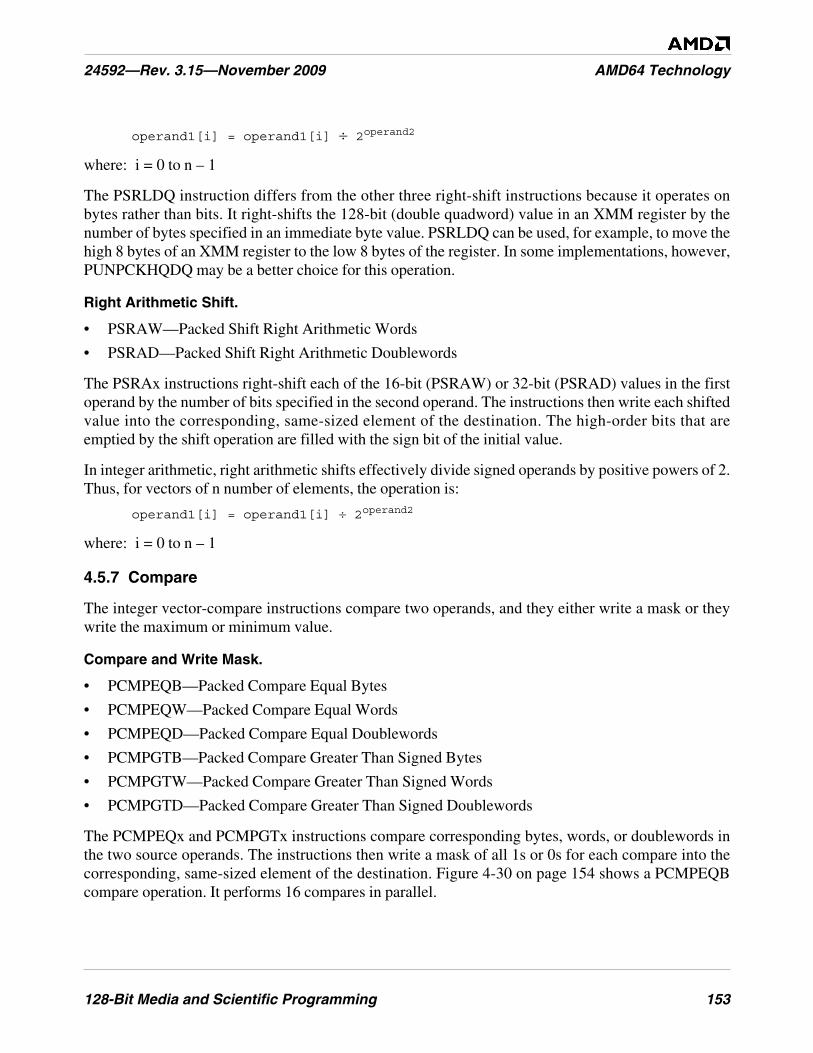
128-Bit Media and Scientific Programming 153
24592—Rev. 3.15—November 2009 AMD64 Technology
operand1[i] = operand1[i] ÷ 2operand2
where: i = 0 to n – 1
The PSRLDQ instruction differs from the other three right-shift instructions because it operates onbytes rather than bits. It right-shifts the 128-bit (double quadword) value in an XMM register by thenumber of bytes specified in an immediate byte value. PSRLDQ can be used, for example, to move thehigh 8 bytes of an XMM register to the low 8 bytes of the register. In some implementations, however,PUNPCKHQDQ may be a better choice for this operation.
Right Arithmetic Shift.
• PSRAW—Packed Shift Right Arithmetic Words
• PSRAD—Packed Shift Right Arithmetic Doublewords
The PSRAx instructions right-shift each of the 16-bit (PSRAW) or 32-bit (PSRAD) values in the firstoperand by the number of bits specified in the second operand. The instructions then write each shiftedvalue into the corresponding, same-sized element of the destination. The high-order bits that areemptied by the shift operation are filled with the sign bit of the initial value.
In integer arithmetic, right arithmetic shifts effectively divide signed operands by positive powers of 2.Thus, for vectors of n number of elements, the operation is:
operand1[i] = operand1[i] ÷ 2operand2
where: i = 0 to n – 1
4.5.7 Compare
The integer vector-compare instructions compare two operands, and they either write a mask or theywrite the maximum or minimum value.
Compare and Write Mask.
• PCMPEQB—Packed Compare Equal Bytes
• PCMPEQW—Packed Compare Equal Words
• PCMPEQD—Packed Compare Equal Doublewords
• PCMPGTB—Packed Compare Greater Than Signed Bytes
• PCMPGTW—Packed Compare Greater Than Signed Words
• PCMPGTD—Packed Compare Greater Than Signed Doublewords
The PCMPEQx and PCMPGTx instructions compare corresponding bytes, words, or doublewords inthe two source operands. The instructions then write a mask of all 1s or 0s for each compare into thecorresponding, same-sized element of the destination. Figure 4-30 on page 154 shows a PCMPEQBcompare operation. It performs 16 compares in parallel.
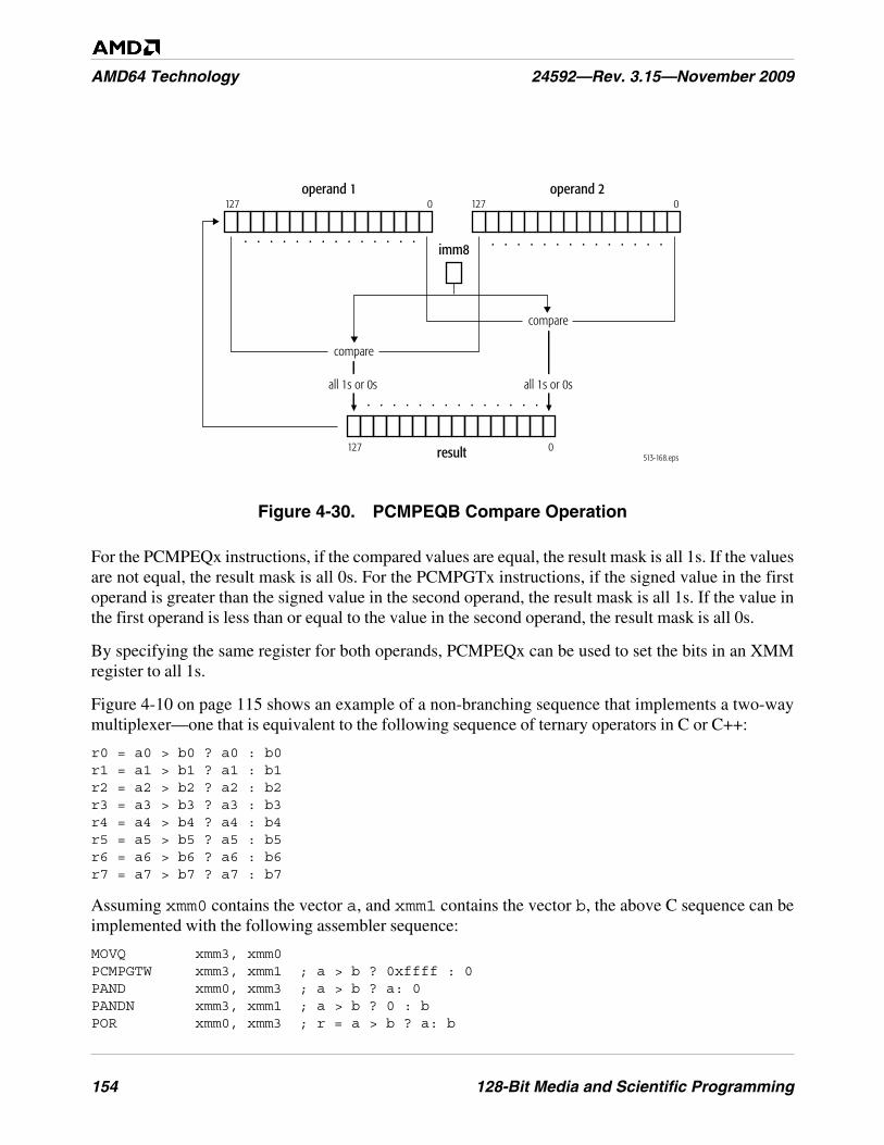
154 128-Bit Media and Scientific Programming
AMD64 Technology 24592—Rev. 3.15—November 2009
Figure 4-30. PCMPEQB Compare Operation
For the PCMPEQx instructions, if the compared values are equal, the result mask is all 1s. If the valuesare not equal, the result mask is all 0s. For the PCMPGTx instructions, if the signed value in the firstoperand is greater than the signed value in the second operand, the result mask is all 1s. If the value inthe first operand is less than or equal to the value in the second operand, the result mask is all 0s.
By specifying the same register for both operands, PCMPEQx can be used to set the bits in an XMMregister to all 1s.
Figure 4-10 on page 115 shows an example of a non-branching sequence that implements a two-waymultiplexer—one that is equivalent to the following sequence of ternary operators in C or C++:
r0 = a0 > b0 ? a0 : b0r1 = a1 > b1 ? a1 : b1r2 = a2 > b2 ? a2 : b2r3 = a3 > b3 ? a3 : b3r4 = a4 > b4 ? a4 : b4r5 = a5 > b5 ? a5 : b5r6 = a6 > b6 ? a6 : b6r7 = a7 > b7 ? a7 : b7
Assuming xmm0 contains the vector a, and xmm1 contains the vector b, the above C sequence can beimplemented with the following assembler sequence:
MOVQ xmm3, xmm0PCMPGTW xmm3, xmm1 ; a > b ? 0xffff : 0PAND xmm0, xmm3 ; a > b ? a: 0PANDN xmm3, xmm1 ; a > b ? 0 : bPOR xmm0, xmm3 ; r = a > b ? a: b
513-168.epsresult
operand 1127 0
127 0
operand 2127 0
imm8
compare
all 1s or 0s all 1s or 0s
compare
. . . . . . . . . . . . . .. . . . . . . . . . . . . .
. . . . . . . . . . . . . .
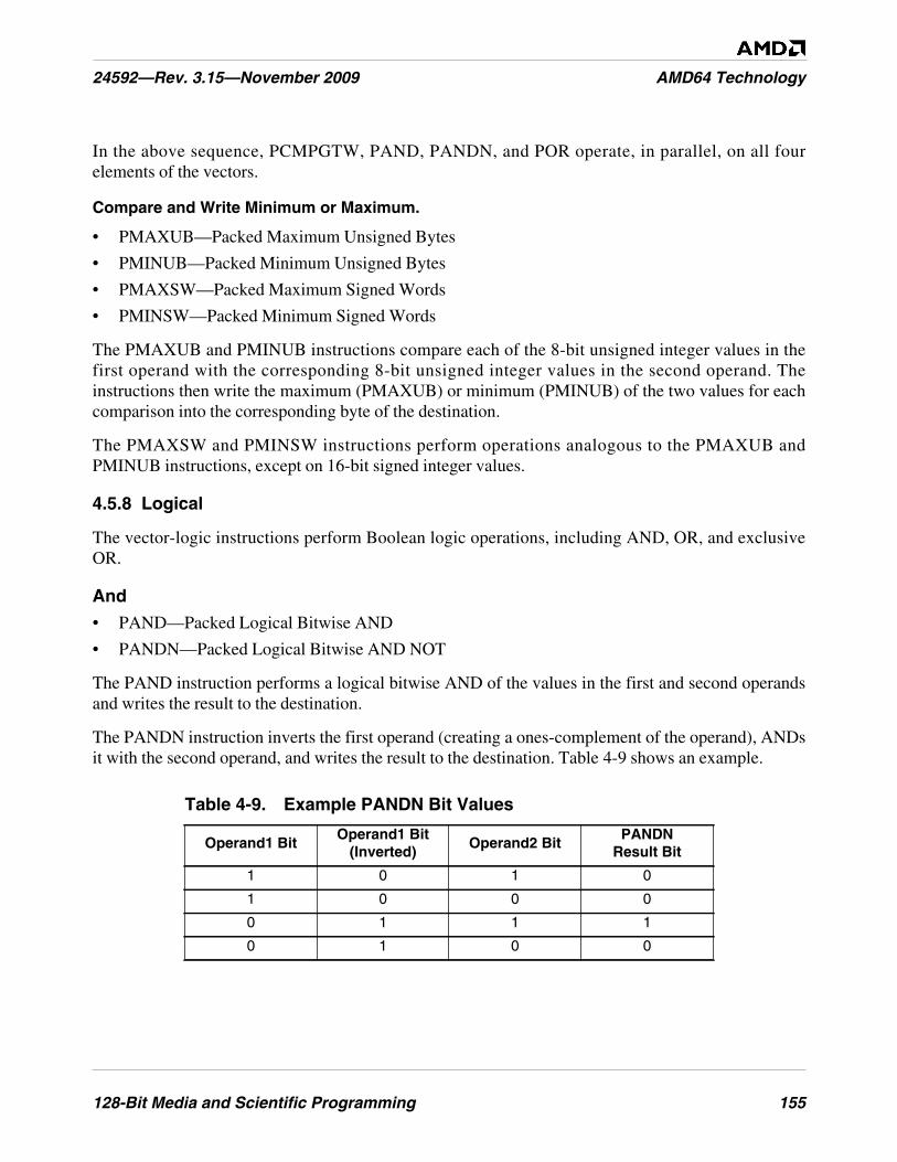
128-Bit Media and Scientific Programming 155
24592—Rev. 3.15—November 2009 AMD64 Technology
In the above sequence, PCMPGTW, PAND, PANDN, and POR operate, in parallel, on all fourelements of the vectors.
Compare and Write Minimum or Maximum.
• PMAXUB—Packed Maximum Unsigned Bytes
• PMINUB—Packed Minimum Unsigned Bytes
• PMAXSW—Packed Maximum Signed Words
• PMINSW—Packed Minimum Signed Words
The PMAXUB and PMINUB instructions compare each of the 8-bit unsigned integer values in thefirst operand with the corresponding 8-bit unsigned integer values in the second operand. Theinstructions then write the maximum (PMAXUB) or minimum (PMINUB) of the two values for eachcomparison into the corresponding byte of the destination.
The PMAXSW and PMINSW instructions perform operations analogous to the PMAXUB andPMINUB instructions, except on 16-bit signed integer values.
4.5.8 Logical
The vector-logic instructions perform Boolean logic operations, including AND, OR, and exclusiveOR.
And
• PAND—Packed Logical Bitwise AND
• PANDN—Packed Logical Bitwise AND NOT
The PAND instruction performs a logical bitwise AND of the values in the first and second operandsand writes the result to the destination.
The PANDN instruction inverts the first operand (creating a ones-complement of the operand), ANDsit with the second operand, and writes the result to the destination. Table 4-9 shows an example.
Table 4-9. Example PANDN Bit Values
Operand1 BitOperand1 Bit
(Inverted)Operand2 Bit
PANDNResult Bit
1 0 1 0
1 0 0 0
0 1 1 1
0 1 0 0
156 128-Bit Media and Scientific Programming
AMD64 Technology 24592—Rev. 3.15—November 2009
Or
• POR—Packed Logical Bitwise OR
The POR instruction performs a logical bitwise OR of the values in the first and second operands andwrites the result to the destination.
Exclusive Or
• PXOR—Packed Logical Bitwise Exclusive OR
The PXOR instruction performs a logical bitwise exclusive OR of the values in the first and secondoperands and writes the result to the destination. PXOR can be used to clear all bits in an XMMregister by specifying the same register for both operands.
4.5.9 Save and Restore State
These instructions save and restore the entire processor state for 128-bit media instructions.
Save and Restore 128-Bit, 64-Bit, and x87 State
• FXSAVE—Save XMM, MMX, and x87 State.
• FXRSTOR—Restore XMM, MMX, and x87 State.
The FXSAVE and FXRSTOR instructions save and restore the entire 512-byte processor state for 128-bit media instructions, 64-bit media instructions, and x87 floating-point instructions. The architecturesupports two memory formats for FXSAVE and FXRSTOR, a 512-byte 32-bit legacy format and a512-byte 64-bit format. Selection of the 32-bit or 64-bit format is determined by the effective operandsize for the FXSAVE and FXRSTOR instructions. For details, see “FXSAVE and FXRSTORInstructions” in Volume 2.
Save and Restore Control and Status
• STMXCSR—Store MXCSR Control/Status Register
• LDMXCSR—Load MXCSR Control/Status Register
The STMXCSR and LDMXCSR instructions save and restore the 32-bit contents of the MXCSRregister. For further information, see “MXCSR Register” on page 117.
4.6 Instruction Summary—Floating-Point Instructions
This section summarizes the functions of the floating-point instructions in the 128-bit mediainstruction subset. These include floating-point instructions that use an XMM register for source ordestination and data-conversion instructions that convert from floating-point to integer formats. For asummary of the integer instructions in the 128-bit media instruction subset, including data-conversioninstructions that convert from integer to floating-point formats, see “Instruction Summary—IntegerInstructions” on page 133.
128-Bit Media and Scientific Programming 157
24592—Rev. 3.15—November 2009 AMD64 Technology
For a summary of the 64-bit media floating-point instructions, see “Instruction Summary—Floating-Point Instructions” on page 223. For a summary of the x87 floating-point instructions, see “InstructionSummary” on page 261.
The instructions are organized here by functional group—such as data-transfer, vector arithmetic, andso on. Software running at any privilege level can use any of these instructions, if the CPUIDinstruction reports support for the instructions (see “Feature Detection” on page 176). More detail onindividual instructions is given in the alphabetically organized “128-Bit Media Instruction Reference”in Volume 4.
4.6.1 Syntax
The 128-bit media floating-point instructions have the same syntax rules as those for the 128-bit mediainteger instructions, described in “Syntax” on page 133. For an illustration of typical syntax, seeFigure 4-16 on page 134.
4.6.2 Data Transfer
The data-transfer instructions copy operands between 32-bit, 64-bit, or 128-bit memory locations andXMM registers. The MOV mnemonic, which stands for move, is a misnomer. A copy function isactually performed instead of a move. A new copy of the source value is created at the destinationaddress, and the original copy remains unchanged at its source location.
Move
• MOVAPS—Move Aligned Packed Single-Precision Floating-Point
• MOVAPD—Move Aligned Packed Double-Precision Floating-Point
• MOVUPS—Move Unaligned Packed Single-Precision Floating-Point
• MOVUPD—Move Unaligned Packed Double-Precision Floating-Point
• MOVHPS—Move High Packed Single-Precision Floating-Point
• MOVHPD—Move High Packed Double-Precision Floating-Point
• MOVLPS—Move Low Packed Single-Precision Floating-Point
• MOVLPD—Move Low Packed Double-Precision Floating-Point
• MOVHLPS—Move Packed Single-Precision Floating-Point High to Low
• MOVLHPS—Move Packed Single-Precision Floating-Point Low to High
• MOVSS—Move Scalar Single--Precision Floating-Point
• MOVSD—Move Scalar Double-Precision Floating-Point
• MOVDDUP—Move Double-Precision and Duplicate
• MOVSLDUP—Move Single-Precision High and Duplicate
• MOVSHDUP—Move Single-Precision Low and Duplicate
Figure 4-31 on page 159 shows the capabilities of the various floating-point move instructions.
158 128-Bit Media and Scientific Programming
AMD64 Technology 24592—Rev. 3.15—November 2009
The MOVAPx instructions copy a vector of four single-precision floating-point values (MOVAPS) or avector of two double-precision floating-point values (MOVAPD) from the second operand to the firstoperand—i.e., from an XMM register or 128-bit memory location or to another XMM register, or viceversa. A general-protection exception occurs if a memory operand is not aligned on a 16-byteboundary.
The MOVUPx instructions perform operations analogous to the MOVAPx instructions, except thatunaligned memory operands do not cause a general-protection exception.
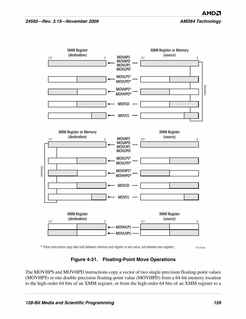
128-Bit Media and Scientific Programming 159
24592—Rev. 3.15—November 2009 AMD64 Technology
Figure 4-31. Floating-Point Move Operations
The MOVHPS and MOVHPD instructions copy a vector of two single-precision floating-point values(MOVHPS) or one double-precision floating-point value (MOVHPD) from a 64-bit memory locationto the high-order 64 bits of an XMM register, or from the high-order 64 bits of an XMM register to a
513-169.eps
MOVAPSMOVAPDMOVUPSMOVUPD
MOVLPS*MOVLPD*
127 0127 0
MOVSD
mem
ory
XMM Register(source)
XMM Register(destination)
XMM Register or Memory(source)
XMM Register(destination)
127 0127 0
MOVLHPS
MOVHLPS
MOVHPS*MOVHPD*
MOVSS
MOVAPSMOVAPDMOVUPSMOVUPD
MOVLPS*MOVLPD*
MOVSD
MOVHPS*MOVHPD*
MOVSS
127 0127 0
mem
ory
XMM Register(source)
XMM Register or Memory(destination)
* These instructions copy data only between memory and regsiter or vice versa, not between two registers.
160 128-Bit Media and Scientific Programming
AMD64 Technology 24592—Rev. 3.15—November 2009
64-bit memory location. In the memory-to-register case, the low-order 64 bits of the destination XMMregister are not modified.
The MOVLPS and MOVLPD instructions copy a vector of two single-precision floating-point values(MOVLPS) or one double-precision floating-point value (MOVLPD) from a 64-bit memory locationto the low-order 64 bits of an XMM register, or from the low-order 64 bits of an XMM register to a 64-bit memory location. In the memory-to-register case, the high-order 64 bits of the destination XMMregister are not modified.
The MOVHLPS instruction copies a vector of two single-precision floating-point values from thehigh-order 64 bits of an XMM register to the low-order 64 bits of another XMM register. The high-order 64 bits of the destination XMM register are not modified. The MOVLHPS instruction performsan analogous operation except in the opposite direct (low-order to high-order), and the low-order 64bits of the destination XMM register are not modified.
The MOVSS instruction copies a scalar single-precision floating-point value from the low-order 32bits of an XMM register or a 32-bit memory location to the low-order 32 bits of another XMM register,or vice versa. If the source operand is an XMM register, the high-order 96 bits of the destination XMMregister are not modified. If the source operand is a 32-bit memory location, the high-order 96 bits ofthe destination XMM register are cleared to all 0s.
The MOVSD instruction copies a scalar double-precision floating-point value from the low-order 64bits of an XMM register or a 64-bit memory location to the low-order 64 bits of another XMM register,or vice versa. If the source operand is an XMM register, the high-order 64 bits of the destination XMMregister are not modified. If the source operand is a memory location, the high-order 64 bits of thedestination XMM register are cleared to all 0s.
The above MOVSD instruction should not be confused with the same-mnemonic MOVSD (movestring doubleword) instruction in the general-purpose instruction set. Assemblers distinguish the twoinstructions by their operand data types.
Move with Duplication. These instructions move two copies of the affected data segments from thesource XMM register or 128-bit memory operand to the target destination register.
The MOVDDUP moves one copy of the lower quadword of the source operand into each quadwordhalf of the destination operand.
The MOVSLDUP instruction moves two copies of the first doubleword of the source operand into thefirst two doubleword segments of the destination operand and moves two copies of the thirddoubleword of the source operand into the third and fourth doubleword segments of the destinationoperand.
The MOVSHDUP instruction moves two copies of the second doubleword of the source operand intothe first two doubleword segments of the destination operand and moves two copies of the fourthdoubleword of the source operand into the upper two doubleword segments of the destination operand.
128-Bit Media and Scientific Programming 161
24592—Rev. 3.15—November 2009 AMD64 Technology
Move Non-Temporal. The move non-temporal instructions are streaming-store instructions. Theyminimize pollution of the cache.
• MOVNTPD—Move Non-Temporal Packed Double-Precision Floating-Point
• MOVNTPS—Move Non-Temporal Packed Single-Precision Floating-Point
• MOVNTSD—Move Non-Temporal Scalar Double-Precision Floating-Point
• MOVNTSS—Move Non-Temporal Scalar Single-Precision Floating-Point
The MOVNTPx instructions copy four packed single-precision floating-point (MOVNTPS) or twopacked double-precision floating-point (MOVNTPD) values from an XMM register into a 128-bitmemory location.
The MOVNTSx instructions store one double precision floating point XMM register value into a 64 bitmemory location or one single precision floating point XMM register value into a 32-bit memorylocation.
These instructions indicate to the processor that their data is non-temporal, which assumes that thedata they reference will be used only once and is therefore not subject to cache-related overhead (asopposed to temporal data, which assumes that the data will be accessed again soon and should becached). The non-temporal instructions use weakly-ordered, write-combining buffering of write data,and they minimize cache pollution. The exact method by which cache pollution is minimized dependson the hardware implementation of the instruction. For further information, see “MemoryOptimization” on page 92.
Move Mask
• MOVMSKPS—Extract Packed Single-Precision Floating-Point Sign Mask
• MOVMSKPD—Extract Packed Double-Precision Floating-Point Sign Mask
The MOVMSKPS instruction copies the sign bits of four single-precision floating-point values in anXMM register to the four low-order bits of a 32-bit or 64-bit general-purpose register, with zero-extension. The MOVMSKPD instruction copies the sign bits of two double-precision floating-pointvalues in an XMM register to the two low-order bits of a general-purpose register, with zero-extension.The result of either instruction is a sign-bit mask that can be used for data-dependent branching. Figure4-32 shows the MOVMSKPS operation.
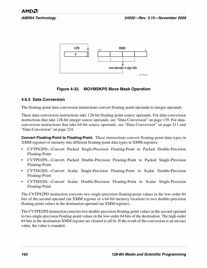
162 128-Bit Media and Scientific Programming
AMD64 Technology 24592—Rev. 3.15—November 2009
Figure 4-32. MOVMSKPS Move Mask Operation
4.6.3 Data Conversion
The floating-point data-conversion instructions convert floating-point operands to integer operands.
These data-conversion instructions take 128-bit floating-point source operands. For data-conversioninstructions that take 128-bit integer source operands, see “Data Conversion” on page 139. For data-conversion instructions that take 64-bit source operands, see “Data Conversion” on page 211 and“Data Conversion” on page 224.
Convert Floating-Point to Floating-Point. These instructions convert floating-point data types inXMM registers or memory into different floating-point data types in XMM registers.
• CVTPS2PD—Convert Packed Single-Precision Floating-Point to Packed Double-PrecisionFloating-Point
• CVTPD2PS—Convert Packed Double-Precision Floating-Point to Packed Single-PrecisionFloating-Point
• CVTSS2SD—Convert Scalar Single-Precision Floating-Point to Scalar Double-PrecisionFloating-Point
• CVTSD2SS—Convert Scalar Double-Precision Floating-Point to Scalar Single-PrecisionFloating-Point
The CVTPS2PD instruction converts two single-precision floating-point values in the low-order 64bits of the second operand (an XMM register or a 64-bit memory location) to two double-precisionfloating-point values in the destination operand (an XMM register).
The CVTPD2PS instruction converts two double-precision floating-point values in the second operandto two single-precision floating-point values in the low-order 64 bits of the destination. The high-order64 bits in the destination XMM register are cleared to all 0s. If the result of the conversion is an inexactvalue, the value is rounded.
513-158.eps
GPR XMM127 0
concatenate 4 sign bits
0
128-Bit Media and Scientific Programming 163
24592—Rev. 3.15—November 2009 AMD64 Technology
The CVTSS2SD instruction converts a single-precision floating-point value in the low-order 32 bits ofthe second operand to a double-precision floating-point value in the low-order 64 bits of thedestination. The high-order 64 bits in the destination XMM register are not modified.
The CVTSD2SS instruction converts a double-precision floating-point value in the low-order 64 bitsof the second operand to a single-precision floating-point value in the low-order 64 bits of thedestination. The three high-order doublewords in the destination XMM register are not modified. If theresult of the conversion is an inexact value, the value is rounded.
Convert Floating-Point to XMM Integer. These instructions convert floating-point data types inXMM registers or memory into integer data types in XMM registers.
• CVTPS2DQ—Convert Packed Single-Precision Floating-Point to Packed Doubleword Integers
• CVTPD2DQ—Convert Packed Double-Precision Floating-Point to Packed Doubleword Integers
• CVTTPS2DQ—Convert Packed Single-Precision Floating-Point to Packed Doubleword Integers,Truncated
• CVTTPD2DQ—Convert Packed Double-Precision Floating-Point to Packed DoublewordIntegers, Truncated
The CVTPS2DQ and CVTTPS2DQ instructions convert four single-precision floating-point values inthe second operand to four 32-bit signed integer values in the destination. For the CVTPS2DQinstruction, if the result of the conversion is an inexact value, the value is rounded, but for theCVTTPS2DQ instruction such a result is truncated (rounded toward zero).
The CVTPD2DQ and CVTTPD2DQ instructions convert two double-precision floating-point valuesin the second operand to two 32-bit signed integer values in the destination. The high-order 64 bits inthe destination XMM register are cleared to all 0s. For the CVTPD2DQ instruction, if the result of theconversion is an inexact value, the value is rounded, but for the CVTTPD2DQ instruction such a resultis truncated (rounded toward zero).
For a description of 128-bit media instructions that convert in the opposite direction—integer tofloating-point—see “Convert Integer to Floating-Point” on page 139.
Convert Floating-Point to MMX™ Integer. These instructions convert floating-point data types inXMM registers or memory into integer data types in MMX registers.
• CVTPS2PI—Convert Packed Single-Precision Floating-Point to Packed Doubleword Integers
• CVTPD2PI—Convert Packed Double-Precision Floating-Point to Packed Doubleword Integers
• CVTTPS2PI—Convert Packed Single-Precision Floating-Point to Packed Doubleword Integers,Truncated
• CVTTPD2PI—Convert Packed Double-Precision Floating-Point to Packed Doubleword Integers,Truncated
The CVTPS2PI and CVTTPS2PI instructions convert two single-precision floating-point values in thelow-order 64 bits of an XMM register or a 64-bit memory location to two 32-bit signed integer valuesin an MMX register. For the CVTPS2PI instruction, if the result of the conversion is an inexact value,
164 128-Bit Media and Scientific Programming
AMD64 Technology 24592—Rev. 3.15—November 2009
the value is rounded, but for the CVTTPS2PI instruction such a result is truncated (rounded towardzero).
The CVTPD2PI and CVTTPD2PI instructions convert two double-precision floating-point values inan XMM register or a 128-bit memory location to two 32-bit signed integer values in an MMX register.For the CVTPD2PI instruction, if the result of the conversion is an inexact value, the value is rounded,but for the CVTTPD2PI instruction such a result is truncated (rounded toward zero).
Before executing a CVTxPS2PI or CVTxPD2PI instruction, software should ensure that the MMXregisters are properly initialized so as to prevent conflict with their aliased use by x87 floating-pointinstructions. This may require clearing the MMX state, as described in “Accessing Operands inMMX™ Registers” on page 188.
For a description of 128-bit media instructions that convert in the opposite direction—integer in MMXregisters to floating-point in XMM registers—see “Convert MMX Integer to Floating-Point” onpage 139. For a summary of instructions that operate on MMX registers, see Chapter 5, “64-Bit MediaProgramming.”
Convert Floating-Point to GPR Integer. These instructions convert floating-point data types inXMM registers or memory into integer data types in GPR registers.
• CVTSS2SI—Convert Scalar Single-Precision Floating-Point to Signed Doubleword or QuadwordInteger
• CVTSD2SI—Convert Scalar Double-Precision Floating-Point to Signed Doubleword orQuadword Integer
• CVTTSS2SI—Convert Scalar Single-Precision Floating-Point to Signed Doubleword orQuadword Integer, Truncated
• CVTTSD2SI—Convert Scalar Double-Precision Floating-Point to Signed Doubleword orQuadword Integer, Truncated
The CVTSS2SI and CVTTSS2SI instructions convert a single-precision floating-point value in thelow-order 32 bits of an XMM register or a 32-bit memory location to a 32-bit or 64-bit signed integervalue in a general-purpose register. For the CVTSS2SI instruction, if the result of the conversion is aninexact value, the value is rounded, but for the CVTTSS2SI instruction such a result is truncated(rounded toward zero).
The CVTSD2SI and CVTTSD2SI instructions convert a double-precision floating-point value in thelow-order 64 bits of an XMM register or a 64-bit memory location to a 32-bit or 64-bit signed integervalue in a general-purpose register. For the CVTSD2SI instruction, if the result of the conversion is aninexact value, the value is rounded, but for the CVTTSD2SI instruction such a result is truncated(rounded toward zero).
For a description of 128-bit media instructions that convert in the opposite direction—integer in GPRregisters to floating-point in XMM registers—see “Convert GPR Integer to Floating-Point” onpage 140. For a summary of instructions that operate on GPR registers, see Chapter 3, “General-Purpose Programming.”
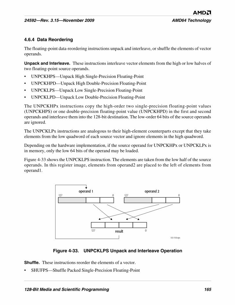
128-Bit Media and Scientific Programming 165
24592—Rev. 3.15—November 2009 AMD64 Technology
4.6.4 Data Reordering
The floating-point data-reordering instructions unpack and interleave, or shuffle the elements of vectoroperands.
Unpack and Interleave. These instructions interleave vector elements from the high or low halves oftwo floating-point source operands.
• UNPCKHPS—Unpack High Single-Precision Floating-Point
• UNPCKHPD—Unpack High Double-Precision Floating-Point
• UNPCKLPS—Unpack Low Single-Precision Floating-Point
• UNPCKLPD—Unpack Low Double-Precision Floating-Point
The UNPCKHPx instructions copy the high-order two single-precision floating-point values(UNPCKHPS) or one double-precision floating-point value (UNPCKHPD) in the first and secondoperands and interleave them into the 128-bit destination. The low-order 64 bits of the source operandsare ignored.
The UNPCKLPx instructions are analogous to their high-element counterparts except that they takeelements from the low quadword of each source vector and ignore elements in the high quadword.
Depending on the hardware implementation, if the source operand for UNPCKHPx or UNPCKLPx isin memory, only the low 64 bits of the operand may be loaded.
Figure 4-33 shows the UNPCKLPS instruction. The elements are taken from the low half of the sourceoperands. In this register image, elements from operand2 are placed to the left of elements fromoperand1.
Figure 4-33. UNPCKLPS Unpack and Interleave Operation
Shuffle. These instructions reorder the elements of a vector.
• SHUFPS—Shuffle Packed Single-Precision Floating-Point
513-159.eps
operand 1
result
127 0operand 2
127 0
127 0
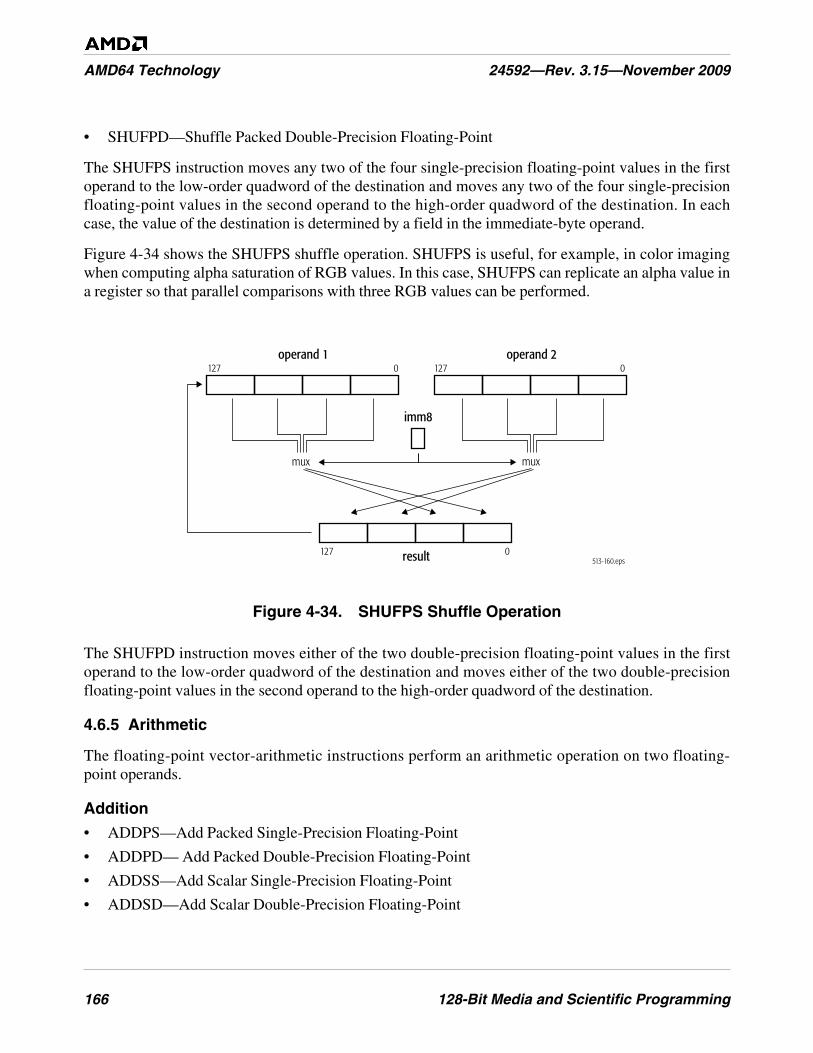
166 128-Bit Media and Scientific Programming
AMD64 Technology 24592—Rev. 3.15—November 2009
• SHUFPD—Shuffle Packed Double-Precision Floating-Point
The SHUFPS instruction moves any two of the four single-precision floating-point values in the firstoperand to the low-order quadword of the destination and moves any two of the four single-precisionfloating-point values in the second operand to the high-order quadword of the destination. In eachcase, the value of the destination is determined by a field in the immediate-byte operand.
Figure 4-34 shows the SHUFPS shuffle operation. SHUFPS is useful, for example, in color imagingwhen computing alpha saturation of RGB values. In this case, SHUFPS can replicate an alpha value ina register so that parallel comparisons with three RGB values can be performed.
Figure 4-34. SHUFPS Shuffle Operation
The SHUFPD instruction moves either of the two double-precision floating-point values in the firstoperand to the low-order quadword of the destination and moves either of the two double-precisionfloating-point values in the second operand to the high-order quadword of the destination.
4.6.5 Arithmetic
The floating-point vector-arithmetic instructions perform an arithmetic operation on two floating-point operands.
Addition
• ADDPS—Add Packed Single-Precision Floating-Point
• ADDPD— Add Packed Double-Precision Floating-Point
• ADDSS—Add Scalar Single-Precision Floating-Point
• ADDSD—Add Scalar Double-Precision Floating-Point
513-160.epsresult
operand 1127 0
127 0
operand 2127 0
imm8
muxmux
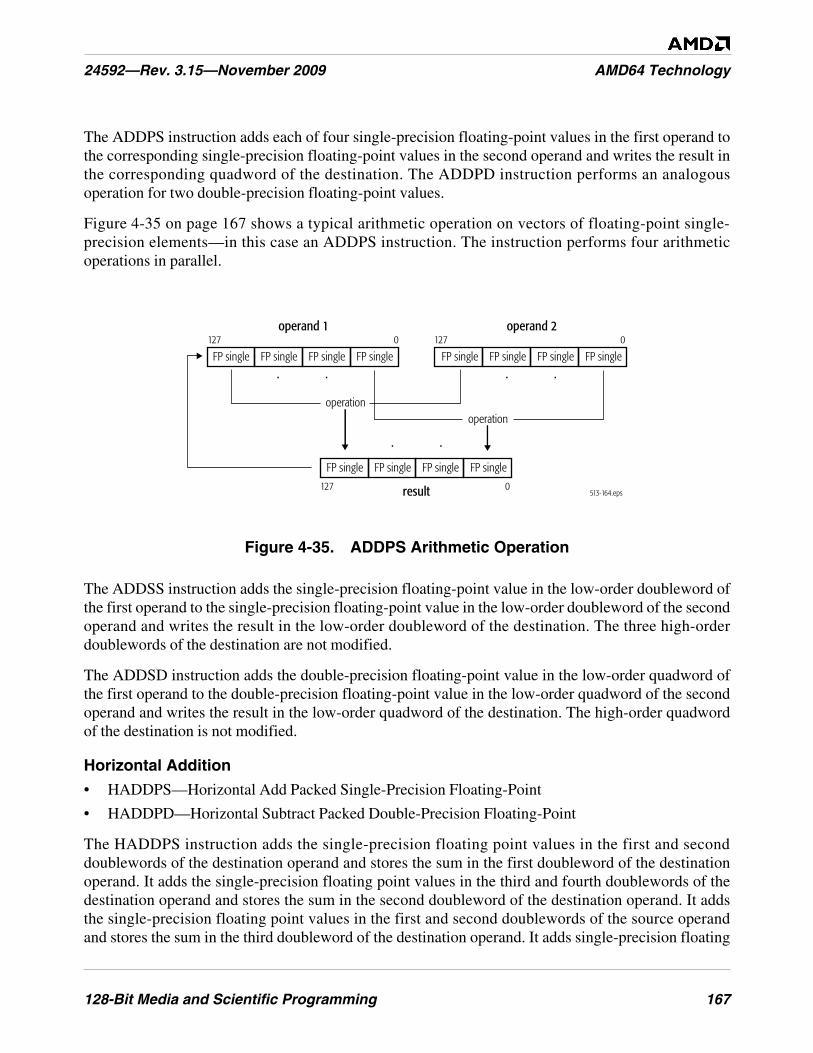
128-Bit Media and Scientific Programming 167
24592—Rev. 3.15—November 2009 AMD64 Technology
The ADDPS instruction adds each of four single-precision floating-point values in the first operand tothe corresponding single-precision floating-point values in the second operand and writes the result inthe corresponding quadword of the destination. The ADDPD instruction performs an analogousoperation for two double-precision floating-point values.
Figure 4-35 on page 167 shows a typical arithmetic operation on vectors of floating-point single-precision elements—in this case an ADDPS instruction. The instruction performs four arithmeticoperations in parallel.
Figure 4-35. ADDPS Arithmetic Operation
The ADDSS instruction adds the single-precision floating-point value in the low-order doubleword ofthe first operand to the single-precision floating-point value in the low-order doubleword of the secondoperand and writes the result in the low-order doubleword of the destination. The three high-orderdoublewords of the destination are not modified.
The ADDSD instruction adds the double-precision floating-point value in the low-order quadword ofthe first operand to the double-precision floating-point value in the low-order quadword of the secondoperand and writes the result in the low-order quadword of the destination. The high-order quadwordof the destination is not modified.
Horizontal Addition
• HADDPS—Horizontal Add Packed Single-Precision Floating-Point
• HADDPD—Horizontal Subtract Packed Double-Precision Floating-Point
The HADDPS instruction adds the single-precision floating point values in the first and seconddoublewords of the destination operand and stores the sum in the first doubleword of the destinationoperand. It adds the single-precision floating point values in the third and fourth doublewords of thedestination operand and stores the sum in the second doubleword of the destination operand. It addsthe single-precision floating point values in the first and second doublewords of the source operandand stores the sum in the third doubleword of the destination operand. It adds single-precision floating
513-164.eps
. .. .
. .
operationoperation
result
operand 1127 0
127 0
operand 2127 0
FP single FP single FP single FP single FP single FP single FP single FP single
FP single FP single FP single FP single
168 128-Bit Media and Scientific Programming
AMD64 Technology 24592—Rev. 3.15—November 2009
point values in the third and fourth doublewords of the source operand and stores the sum in the fourthdoubleword of the destination operand.
The HADDPD instruction adds the two double-precision floating point values in the quadword halvesof the destination operand and stores the sum in the first quadword of the destination. It adds the valuesin the two quadword halves of the source register and stores the sum in the second quadword of thedestination register.
Subtraction
• SUBPS—Subtract Packed Single-Precision Floating-Point
• SUBPD—Subtract Packed Double-Precision Floating-Point
• SUBSS—Subtract Scalar Single-Precision Floating-Point
• SUBSD—Subtract Scalar Double-Precision Floating-Point
The SUBPS instruction subtracts each of four single-precision floating-point values in the secondoperand from the corresponding single-precision floating-point value in the first operand and writesthe result in the corresponding quadword of the destination. The SUBPD instruction performs ananalogous operation for two double-precision floating-point values.
For vectors of n number of elements, the operations are:
operand1[i] = operand1[i] - operand2[i]
where: i = 0 to n – 1
The SUBSS instruction subtracts the single-precision floating-point value in the low-orderdoubleword of the second operand from the corresponding single-precision floating-point value in thelow-order doubleword of the first operand and writes the result in the low-order doubleword of thedestination. The three high-order doublewords of the destination are not modified.
The SUBSD instruction subtracts the double-precision floating-point value in the low-order quadwordof the second operand from the corresponding double-precision floating-point value in the low-orderquadword of the first operand and writes the result in the low-order quadword of the destination. Thehigh-order quadword of the destination is not modified.
Horizontal Subtraction
• HSUBPS—Horizontal Subtract Packed Single-Precision Floating-Point
• HSUBPD—Horizontal Subtract Packed Double-Precision Floating-Point
The HSUBPS instruction subtracts the packed-singled precision operand in the second doubleword ofthe destination register from that in the first doubleword of the destination register and stores the resultin the first doubleword of the destination register. It subtracts the fourth doubleword of the destinationoperand from the third doubleword of the destination operand and stores the result in the seconddoubleword of the destination. It subtracts the packed-singled precision operand in the seconddoubleword of the source register from that in the first doubleword of the source register and stores theresult in the third doubleword of the destination register. It subtracts the fourth doubleword of the
128-Bit Media and Scientific Programming 169
24592—Rev. 3.15—November 2009 AMD64 Technology
source operand from the third doubleword of the source operand and stores the result in the fourthdoubleword of the destination.
The HSUBPD instruction subtracts the second quadword of the destination register from the firstquadword of the destination operand and stores the difference in the first quadword of the destinationregister. The difference from the subtraction of the first quadword of the source operand from thesecond quadword of the source operand is stored in the second quadword of the destination operand.
Simultaneous Addition and Subtraction
• ADDSUBPS—Add/Subtract Packed Single-Precision Floating-Point
• ADDSUBPD—Add/Subtract Packed Double-Precision Floating-Point
The ADDSUBPS instruction adds the second and fourth doublewords of the source operand to thesecond and fourth doublewords, respectively, of the destination operand and stores the resulting sumsin the second and fourth doublewords of the destination operand; subtracts the first and thirddoublewords of the first operand from the first and third doublewords of the destination operand andstores the resulting differences in the first and third doublewords of the destination operand.
The ADDSUBPD instruction subtracts the first quadword of the source operand from the firstquadword of the destination operand and stores the difference in the first quadword of the destinationoperand; adds the second quadword of the source operand to the second quadword of the destinationoperand and stores the sum in the second quadword of the destination operand.
Multiplication
• MULPS—Multiply Packed Single-Precision Floating-Point
• MULPD—Multiply Packed Double-Precision Floating-Point
• MULSS—Multiply Scalar Single-Precision Floating-Point
• MULSD—Multiply Scalar Double-Precision Floating-Point
The MULPS instruction multiplies each of four single-precision floating-point values in the firstoperand by the corresponding single-precision floating-point value in the second operand and writesthe result in the corresponding doubleword of the destination. The MULPD instruction performs ananalogous operation for two double-precision floating-point values.
The MULSS instruction multiplies the single-precision floating-point value in the low-orderdoubleword of the first operand by the single-precision floating-point value in the low-orderdoubleword of the second operand and writes the result in the low-order doubleword of the destination.The three high-order doublewords of the destination are not modified.
The MULSD instruction multiplies the double-precision floating-point value in the low-orderquadword of the first operand by the double-precision floating-point value in the low-order quadwordof the second operand and writes the result in the low-order quadword of the destination. The high-order quadword of the destination is not modified.
170 128-Bit Media and Scientific Programming
AMD64 Technology 24592—Rev. 3.15—November 2009
Division
• DIVPS—Divide Packed Single-Precision Floating-Point
• DIVPD—Divide Packed Double-Precision Floating-Point
• DIVSS—Divide Scalar Single-Precision Floating-Point
• DIVSD—Divide Scalar Double-Precision Floating-Point
The DIVPS instruction divides each of the four single-precision floating-point values in the firstoperand by the corresponding single-precision floating-point value in the second operand and writesthe result in the corresponding quadword of the destination. The DIVPD instruction performs ananalogous operation for two double-precision floating-point values. For vectors of n number ofelements, the operations are:
operand1[i] = operand1[i] ÷ operand2[i]
where: i = 0 to n – 1
The DIVSS instruction divides the single-precision floating-point value in the low-order doublewordof the first operand by the single-precision floating-point value in the low-order doubleword of thesecond operand and writes the result in the low-order doubleword of the destination. The three high-order doublewords of the destination are not modified.
The DIVSD instruction divides the double-precision floating-point value in the low-order quadword ofthe first operand by the double-precision floating-point value in the low-order quadword of the secondoperand and writes the result in the low-order quadword of the destination. The high-order quadwordof the destination is not modified.
If accuracy requirements allow, convert floating-point division by a constant to a multiply by thereciprocal. Divisors that are powers of two and their reciprocals are exactly representable, andtherefore do not cause an accuracy issue, except for the rare cases in which the reciprocal overflows orunderflows.
Square Root
• SQRTPS—Square Root Packed Single-Precision Floating-Point
• SQRTPD—Square Root Packed Double-Precision Floating-Point
• SQRTSS—Square Root Scalar Single-Precision Floating-Point
• SQRTSD—Square Root Scalar Double-Precision Floating-Point
The SQRTPS instruction computes the square root of each of four single-precision floating-pointvalues in the second operand (an XMM register or 128-bit memory location) and writes the result inthe corresponding doubleword of the destination. The SQRTPD instruction performs an analogousoperation for two double-precision floating-point values.
The SQRTSS instruction computes the square root of the low-order single-precision floating-pointvalue in the second operand (an XMM register or 32-bit memory location) and writes the result in the
128-Bit Media and Scientific Programming 171
24592—Rev. 3.15—November 2009 AMD64 Technology
low-order doubleword of the destination. The three high-order doublewords of the destination XMMregister are not modified.
The SQRTSD instruction computes the square root of the low-order double-precision floating-pointvalue in the second operand (an XMM register or 64-bit memory location) and writes the result in thelow-order quadword of the destination. The high-order quadword of the destination XMM register isnot modified.
Reciprocal Square Root
• RSQRTPS—Reciprocal Square Root Packed Single-Precision Floating-Point
• RSQRTSS—Reciprocal Square Root Scalar Single-Precision Floating-Point
The RSQRTPS instruction computes the approximate reciprocal of the square root of each of foursingle-precision floating-point values in the second operand (an XMM register or 128-bit memorylocation) and writes the result in the corresponding doubleword of the destination.
The RSQRTSS instruction computes the approximate reciprocal of the square root of the low-ordersingle-precision floating-point value in the second operand (an XMM register or 32-bit memorylocation) and writes the result in the low-order doubleword of the destination. The three high-orderdoublewords in the destination XMM register are not modified.
For both RSQRTPS and RSQRTSS, the maximum relative error is less than or equal to 1.5 * 2–12.
Reciprocal Estimation
• RCPPS—Reciprocal Packed Single-Precision Floating-Point
• RCPSS—Reciprocal Scalar Single-Precision Floating-Point
The RCPPS instruction computes the approximate reciprocal of each of the four single-precisionfloating-point values in the second operand (an XMM register or 128-bit memory location) and writesthe result in the corresponding doubleword of the destination.
The RCPSS instruction computes the approximate reciprocal of the low-order single-precisionfloating-point value in the second operand (an XMM register or 32-bit memory location) and writesthe result in the low-order doubleword of the destination. The three high-order doublewords in thedestination are not modified.
For both RCPPS and RCPSS, the maximum relative error is less than or equal to 1.5 * 2–12.
4.6.6 Compare
The floating-point vector-compare instructions compare two operands, and they either write a mask, orthey write the maximum or minimum value, or they set flags. Compare instructions can be used toavoid branches. Figure 4-10 on page 115 shows an example of using compare instructions.
Compare and Write Mask
• CMPPS—Compare Packed Single-Precision Floating-Point
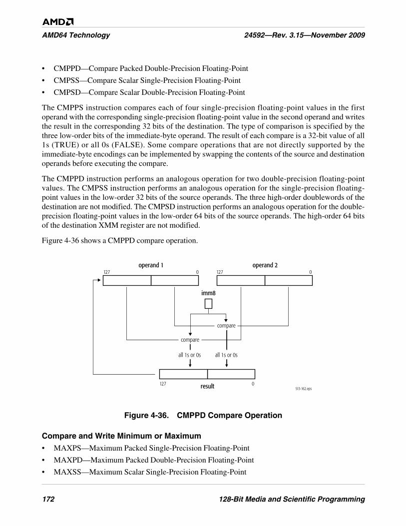
172 128-Bit Media and Scientific Programming
AMD64 Technology 24592—Rev. 3.15—November 2009
• CMPPD—Compare Packed Double-Precision Floating-Point
• CMPSS—Compare Scalar Single-Precision Floating-Point
• CMPSD—Compare Scalar Double-Precision Floating-Point
The CMPPS instruction compares each of four single-precision floating-point values in the firstoperand with the corresponding single-precision floating-point value in the second operand and writesthe result in the corresponding 32 bits of the destination. The type of comparison is specified by thethree low-order bits of the immediate-byte operand. The result of each compare is a 32-bit value of all1s (TRUE) or all 0s (FALSE). Some compare operations that are not directly supported by theimmediate-byte encodings can be implemented by swapping the contents of the source and destinationoperands before executing the compare.
The CMPPD instruction performs an analogous operation for two double-precision floating-pointvalues. The CMPSS instruction performs an analogous operation for the single-precision floating-point values in the low-order 32 bits of the source operands. The three high-order doublewords of thedestination are not modified. The CMPSD instruction performs an analogous operation for the double-precision floating-point values in the low-order 64 bits of the source operands. The high-order 64 bitsof the destination XMM register are not modified.
Figure 4-36 shows a CMPPD compare operation.
Figure 4-36. CMPPD Compare Operation
Compare and Write Minimum or Maximum
• MAXPS—Maximum Packed Single-Precision Floating-Point
• MAXPD—Maximum Packed Double-Precision Floating-Point
• MAXSS—Maximum Scalar Single-Precision Floating-Point
513-162.epsresult
operand 1127 0
127 0
operand 2127 0
imm8
compare
all 1s or 0s all 1s or 0s
compare
128-Bit Media and Scientific Programming 173
24592—Rev. 3.15—November 2009 AMD64 Technology
• MAXSD—Maximum Scalar Double-Precision Floating-Point
• MINPS—Minimum Packed Single-Precision Floating-Point
• MINPD—Minimum Packed Double-Precision Floating-Point
• MINSS—Minimum Scalar Single-Precision Floating-Point
• MINSD—Minimum Scalar Double-Precision Floating-Point
The MAXPS and MINPS instructions compare each of four single-precision floating-point values inthe first operand with the corresponding single-precision floating-point value in the second operandand writes the maximum or minimum, respectively, of the two values in the corresponding doublewordof the destination. The MAXPD and MINPD instructions perform analogous operations on pairs ofdouble-precision floating-point values.
The MAXSS and MINSS instructions compare the single-precision floating-point value in the low-order 32 bits of the first operand with the single-precision floating-point value in the low-order 32 bitsof the second operand and writes the maximum or minimum, respectively, of the two values in the low-order 32 bits of the destination. The three high-order doublewords of the destination XMM register arenot modified.
The MAXSD and MINSD instructions compare the double-precision floating-point value in the low-order 64 bits of the first operand with the double-precision floating-point value in the low-order 64 bitsof the second operand and writes the maximum or minimum, respectively, of the two values in the low-order quadword of the destination. The high-order quadword of the destination XMM register is notmodified.
The MINx and MAXx instructions are useful for clamping (saturating) values, such as color values in3D geometry and rasterization.
Compare and Write rFLAGS
• COMISS—Compare Ordered Scalar Single-Precision Floating-Point
• COMISD—Compare Ordered Scalar Double-Precision Floating-Point
• UCOMISS—Unordered Compare Scalar Single-Precision Floating-Point
• UCOMISD—Unordered Compare Scalar Double-Precision Floating-Point
The COMISS instruction performs an ordered compare of the single-precision floating-point value inthe low-order 32 bits of the first operand with the single-precision floating-point value in the low-order32 bits of the second operand and sets the zero flag (ZF), parity flag (PF), and carry flag (CF) bits inthe rFLAGS register to reflect the result of the compare. The OF, AF, and SF bits in rFLAGS are set tozero.
The COMISD instruction performs an analogous operation on the double-precision floating-pointvalues in the low-order 64 bits of the source operands. The UCOMISS and UCOMISD instructionsperform an analogous, but unordered, compare operations. Figure 4-37 on page 174 shows a COMISDcompare operation.
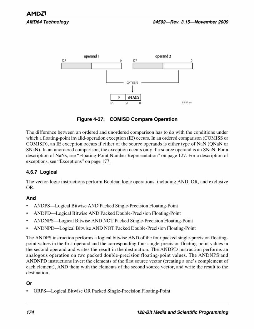
174 128-Bit Media and Scientific Programming
AMD64 Technology 24592—Rev. 3.15—November 2009
Figure 4-37. COMISD Compare Operation
The difference between an ordered and unordered comparison has to do with the conditions underwhich a floating-point invalid-operation exception (IE) occurs. In an ordered comparison (COMISS orCOMISD), an IE exception occurs if either of the source operands is either type of NaN (QNaN orSNaN). In an unordered comparison, the exception occurs only if a source operand is an SNaN. For adescription of NaNs, see “Floating-Point Number Representation” on page 127. For a description ofexceptions, see “Exceptions” on page 177.
4.6.7 Logical
The vector-logic instructions perform Boolean logic operations, including AND, OR, and exclusiveOR.
And
• ANDPS—Logical Bitwise AND Packed Single-Precision Floating-Point
• ANDPD—Logical Bitwise AND Packed Double-Precision Floating-Point
• ANDNPS—Logical Bitwise AND NOT Packed Single-Precision Floating-Point
• ANDNPD—Logical Bitwise AND NOT Packed Double-Precision Floating-Point
The ANDPS instruction performs a logical bitwise AND of the four packed single-precision floating-point values in the first operand and the corresponding four single-precision floating-point values inthe second operand and writes the result in the destination. The ANDPD instruction performs ananalogous operation on two packed double-precision floating-point values. The ANDNPS andANDNPD instructions invert the elements of the first source vector (creating a one’s complement ofeach element), AND them with the elements of the second source vector, and write the result to thedestination.
Or
• ORPS—Logical Bitwise OR Packed Single-Precision Floating-Point
513-161.eps
operand 1127 0
operand 2127 0
compare
03163
rFLAGS0
128-Bit Media and Scientific Programming 175
24592—Rev. 3.15—November 2009 AMD64 Technology
• ORPD—Logical Bitwise OR Packed Double-Precision Floating-Point
The ORPS instruction performs a logical bitwise OR of four single-precision floating-point values inthe first operand and the corresponding four single-precision floating-point values in the secondoperand and writes the result in the destination. The ORPD instruction performs an analogousoperation on pairs of two double-precision floating-point values.
Exclusive Or
• XORPS—Logical Bitwise Exclusive OR Packed Single-Precision Floating-Point
• XORPD—Logical Bitwise Exclusive OR Packed Double-Precision Floating-Point
The XORPS instruction performs a logical bitwise exclusive OR of four single-precision floating-point values in the first operand and the corresponding four single-precision floating-point values inthe second operand and writes the result in the destination. The XORPD instruction performs ananalogous operation on pairs of two double-precision floating-point values.
4.7 Instruction Effects on Flags
The STMXCSR and LDMXCSR instructions, described in “Save and Restore State” on page 156,read and write flags in the MXCSR register. For a description of the MXCSR register, see “MXCSRRegister” on page 117.
The COMISS, COMISD, UCOMISS, and UCOMISD instructions, described in “Compare” onpage 171, write flag bits in the rFLAGS register. For a description of the rFLAGS register, see “FlagsRegister” on page 33.
4.8 Instruction Prefixes
Instruction prefixes, in general, are described in “Instruction Prefixes” on page 71. The followingrestrictions apply to the use of instruction prefixes with 128-bit media instructions.
4.8.1 Supported Prefixes
The following prefixes can be used with 128-bit media instructions:
• Address-Size Override—The 67h prefix affects only operands in memory. The prefix is ignored byall other 128-bit media instructions.
• Operand-Size Override—The 66h prefix is used to form the opcodes of certain 128-bit mediainstructions. The prefix is ignored by all other 128-bit media instructions.
• Segment Overrides—The 2Eh (CS), 36h (SS), 3Eh (DS), 26h (ES), 64h (FS), and 65h (GS)prefixes affect only operands in memory. In 64-bit mode, the contents of the CS, DS, ES, SSsegment registers are ignored.
176 128-Bit Media and Scientific Programming
AMD64 Technology 24592—Rev. 3.15—November 2009
• REP—The F2 and F3h prefixes do not function as repeat prefixes for 128-bit media instructions.Instead, they are used to form the opcodes of certain 128-bit media instructions. The prefixes areignored by all other 128-bit media instructions.
• REX—The REX prefixes affect operands that reference a GPR or XMM register when running in64-bit mode. It allows access to the full 64-bit width of any of the 16 extended GPRs and to any ofthe 16 extended XMM registers. The REX prefix also affects the FXSAVE and FXRSTORinstructions, in which it selects between two types of 512-byte memory-image format, as describedin “Media and x87 Processor State” in Volume 2. The prefix is ignored by all other 128-bit mediainstructions.
4.8.2 Special-Use and Reserved Prefixes
The following prefixes are used as opcode bytes in some 128-bit media instructions and are reserved inall other 128-bit media instructions:
• Operand-Size Override—The 66h prefix.
• REP—The F2 and F3h prefixes.
4.8.3 Prefixes That Cause Exceptions
The following prefixes cause an exception:
• LOCK—The F0h prefix causes an invalid-opcode exception when used with 128-bit mediainstructions.
4.9 Feature Detection
Before executing 128-bit media instructions, software should determine whether the processorsupports the technology by executing the CPUID instruction. “Feature Detection” on page 74describes how software uses the CPUID instruction to detect feature support. For full support of the128-bit media instructions documented here, the following features require detection:
• SSE, indicated by EDX bit 25 returned by CPUID function 0000_0001h.
• SSE2, indicated by EDX bit 26 returned by CPUID function 0000_0001h.
• SSE3, indicated by ECX bit 0 returned by CPUID function 0000_0001h.
• SSE4A, indicated by ECX bit 6 returned by CPUID function 8000_0001h.
• FXSAVE and FXRSTOR, indicated by EDX bit 24 returned by CPUID functions 0000_0001h and8000_0001h.
• Misaligned SSE memory access mode is indicated by ECX bit 7 returned by CPUID function8000_0001h. (See “Misaligned Exception Mask (MM)” on page 120 for further details.
Software that runs in long mode should also check for the following support:
• Long Mode, indicated by bit 29 of CPUID function 8000_0001h.
128-Bit Media and Scientific Programming 177
24592—Rev. 3.15—November 2009 AMD64 Technology
See “Processor Feature Identification” in Volume 2 for a full description of the CPUID instruction andits function codes.
In addition, the operating system must support the FXSAVE and FXRSTOR instructions (by havingset CR4.OSFXSR = 1), and it may wish to support SIMD floating-point exceptions (by having setCR4.OSXMMEXCPT = 1). For details, see “System-Control Registers” in Volume 2.
4.10 Exceptions
Types of Exceptions. 128-bit media instructions can generate two types of exceptions:
• General-Purpose Exceptions, described below in “General-Purpose Exceptions”
• SIMD Floating-Point Exception, described below in “SIMD Floating-Point Exception Causes” onpage 178
Relation to x87 Exceptions. Although the 128-bit media instructions and the x87 floating-pointinstructions each have certain exceptions with the same names, the exception-reporting and exception-handling methods used by the two instruction subsets are distinct and independent of each other. Ifprocedures using both types of instructions are run in the same operating environment, separateservices routines should be provided for the exceptions of each type of instruction subset.
4.10.1 General-Purpose Exceptions
The sections below list general-purpose exceptions generated and not generated by 128-bit mediainstructions. For a summary of the general-purpose exception mechanism, see “Interrupts andExceptions” on page 86. For details about each exception and its potential causes, see “Exceptions andInterrupts” in Volume 2.
Exceptions Generated. The 128-bit media instructions can generate the following general-purposeexceptions:
• #DB—Debug Exception (Vector 1)
• #UD—Invalid-Opcode Exception (Vector 6)
• #NM—Device-Not-Available Exception (Vector 7)
• #DF—Double-Fault Exception (Vector 8)
• #SS—Stack Exception (Vector 12)
• #GP—General-Protection Exception (Vector 13)
• #PF—Page-Fault Exception (Vector 14)
• #MF—x87 Floating-Point Exception-Pending (Vector 16)
• #AC—Alignment-Check Exception (Vector 17)
• #MC—Machine-Check Exception (Vector 18)
• #XF—SIMD Floating-Point Exception (Vector 19)
178 128-Bit Media and Scientific Programming
AMD64 Technology 24592—Rev. 3.15—November 2009
A device-not-available exception (#NM) can occur if an attempt is made to execute a 128-bit mediainstruction when the task switch bit (TS) of the control register (CR0) is set to 1 (CR0.TS = 1).
An invalid-opcode exception (#UD) can occur if:
• a CPUID feature flag indicates that a feature is not supported (see “Feature Detection” onpage 176), or
• an FXSAVE or FXRSTOR instruction is executed when the floating-point software-emulation(EM) bit in control register 0 is set to 1 (CR0.EM = 1), or
• a SIMD floating-point exception occurs when the operating-system XMM exception support bit(OSXMMEXCPT) in control register 4 is cleared to 0 (CR4.OSXMMEXCPT = 0).
Only the following 128-bit media instructions, all of which can access an MMX register, can cause an#MF exception:
• Data Conversion: CVTPD2PI, CVTPS2PI, CPTPI2PD, CVTPI2PS, CVTTPD2PI, CVTTPS2PI.
• Data Transfer: MOVDQ2Q, MOVQ2DQ.
For details on the system control-register bits, see “System-Control Registers” in Volume 2. For detailson the machine-check mechanism, see “Machine Check Mechanism” in Volume 2.
For details on #XF exceptions, see “SIMD Floating-Point Exception Causes” on page 178.
Exceptions Not Generated. The 128-bit media instructions do not generate the following general-purpose exceptions:
• #DE—Divide-by-zero-error exception (Vector 0)
• Non-Maskable-Interrupt Exception (Vector 2)
• #BP—Breakpoint Exception (Vector 3)
• #OF—Overflow exception (Vector 4)
• #BR—Bound-range exception (Vector 5)
• Coprocessor-segment-overrun exception (Vector 9)
• #TS—Invalid-TSS exception (Vector 10)
• #NP—Segment-not-present exception (Vector 11)
• #MC—Machine-check exception (Vector 18)
For details on all general-purpose exceptions, see “Exceptions and Interrupts” in Volume 2.
4.10.2 SIMD Floating-Point Exception Causes
The SIMD floating-point exception is the logical OR of the six floating-point exceptions (IE, DE, ZE,OE, UE, PE) that are reported (signalled) in the MXCSR register’s exception flags (“MXCSRRegister” on page 117). Each of these six exceptions can be either masked or unmasked by software,using the mask bits in the MXCSR register.
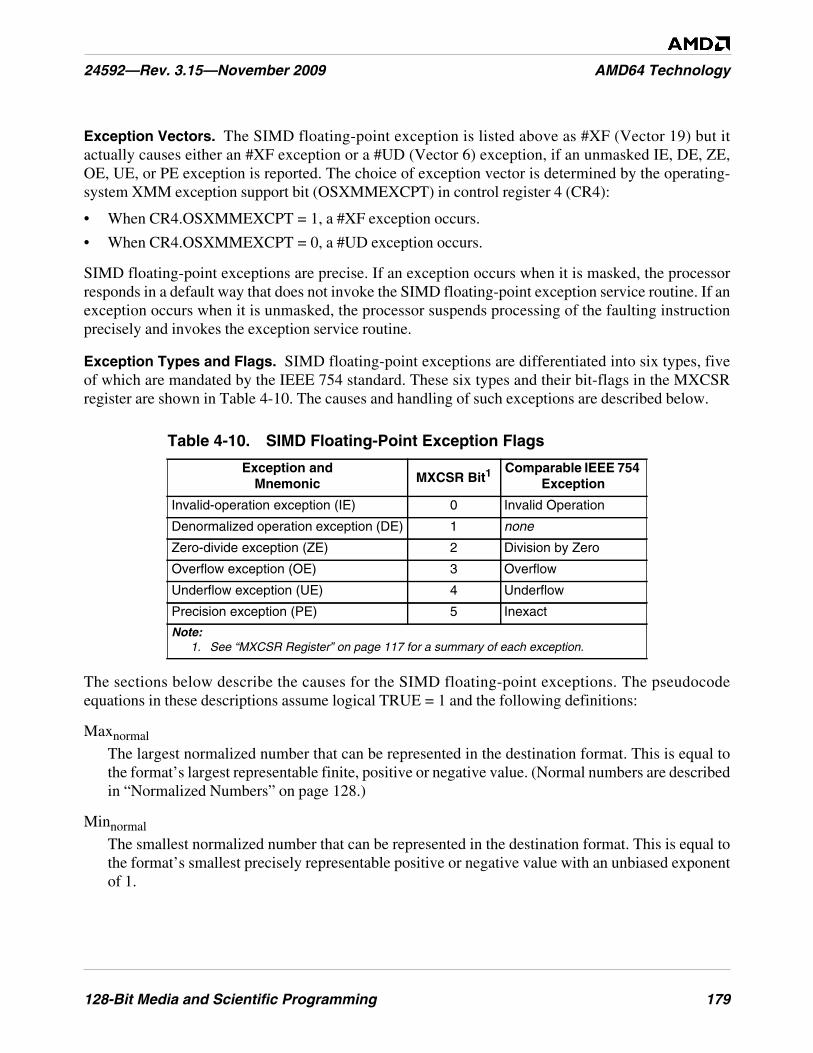
128-Bit Media and Scientific Programming 179
24592—Rev. 3.15—November 2009 AMD64 Technology
Exception Vectors. The SIMD floating-point exception is listed above as #XF (Vector 19) but itactually causes either an #XF exception or a #UD (Vector 6) exception, if an unmasked IE, DE, ZE,OE, UE, or PE exception is reported. The choice of exception vector is determined by the operating-system XMM exception support bit (OSXMMEXCPT) in control register 4 (CR4):
• When CR4.OSXMMEXCPT = 1, a #XF exception occurs.
• When CR4.OSXMMEXCPT = 0, a #UD exception occurs.
SIMD floating-point exceptions are precise. If an exception occurs when it is masked, the processorresponds in a default way that does not invoke the SIMD floating-point exception service routine. If anexception occurs when it is unmasked, the processor suspends processing of the faulting instructionprecisely and invokes the exception service routine.
Exception Types and Flags. SIMD floating-point exceptions are differentiated into six types, fiveof which are mandated by the IEEE 754 standard. These six types and their bit-flags in the MXCSRregister are shown in Table 4-10. The causes and handling of such exceptions are described below.
The sections below describe the causes for the SIMD floating-point exceptions. The pseudocodeequations in these descriptions assume logical TRUE = 1 and the following definitions:
Maxnormal
The largest normalized number that can be represented in the destination format. This is equal tothe format’s largest representable finite, positive or negative value. (Normal numbers are describedin “Normalized Numbers” on page 128.)
Minnormal
The smallest normalized number that can be represented in the destination format. This is equal tothe format’s smallest precisely representable positive or negative value with an unbiased exponentof 1.
Table 4-10. SIMD Floating-Point Exception Flags
Exception andMnemonic MXCSR Bit1
Comparable IEEE 754Exception
Invalid-operation exception (IE) 0 Invalid Operation
Denormalized operation exception (DE) 1 none
Zero-divide exception (ZE) 2 Division by Zero
Overflow exception (OE) 3 Overflow
Underflow exception (UE) 4 Underflow
Precision exception (PE) 5 Inexact
Note:1. See “MXCSR Register” on page 117 for a summary of each exception.
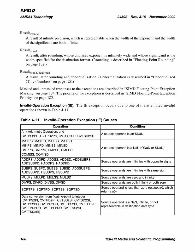
180 128-Bit Media and Scientific Programming
AMD64 Technology 24592—Rev. 3.15—November 2009
Resultinfinite
A result of infinite precision, which is representable when the width of the exponent and the widthof the significand are both infinite.
Resultround
A result, after rounding, whose unbiased exponent is infinitely wide and whose significand is thewidth specified for the destination format. (Rounding is described in “Floating-Point Rounding”on page 132.)
Resultround, denormal
A result, after rounding and denormalization. (Denormalization is described in “Denormalized(Tiny) Numbers” on page 128.)
Masked and unmasked responses to the exceptions are described in “SIMD Floating-Point ExceptionMasking” on page 184. The priority of the exceptions is described in “SIMD Floating-Point ExceptionPriority” on page 182.
Invalid-Operation Exception (IE). The IE exception occurs due to one of the attempted invalidoperations shown in Table 4-11.
Table 4-11. Invalid-Operation Exception (IE) Causes
Operation Condition
Any Arithmetic Operation, andCVTPS2PD, CVTPD2PS, CVTSS2SD, CVTSD2SS
A source operand is an SNaN
MAXPS, MAXPD, MAXSS, MAXSDMINPS, MINPD, MINSS, MINSDCMPPS, CMPPD, CMPSS, CMPSDCOMISS, COMISD
A source operand is a NaN (QNaN or SNaN)
ADDPS, ADDPD, ADDSS, ADDSD, ADDSUBPS.ADDSUBPD, HADDPS, HADDPD
Source operands are infinities with opposite signs
SUBPS, SUBPD, SUBSS, SUBSD, ADDSUBPS,ADDSUBPD, HSUBPS, HSUBPD
Source operands are infinities with same sign
MULPS, MULPD, MULSS, MULSD Source operands are zero and infinity
DIVPS, DIVPD, DIVSS, DIVSD Source operands are both infinity or both zero
SQRTPS, SQRTPD, SQRTSS, SQRTSDSource operand is less than zero (except ±0, whichreturns ±0)
Data conversion from floating-point to integer(CVTPS2PI, CVTPD2PI, CVTSS2SI, CVTSD2SI,CVTPS2DQ, CVTPD2DQ, CVTTPS2PI, CVTTPD2PI,CVTTPD2DQ, CVTTPS2DQ, CVTTSS2SI,CVTTSD2SI)
Source operand is a NaN, infinite, or notrepresentable in destination data type
128-Bit Media and Scientific Programming 181
24592—Rev. 3.15—November 2009 AMD64 Technology
Denormalized-Operand Exception (DE). The DE exception occurs when one of the sourceoperands of an instruction is in denormalized form, as described in “Denormalized (Tiny) Numbers”on page 128.
Zero-Divide Exception (ZE). The ZE exception occurs when and instruction attempts to divide zerointo a non-zero finite dividend.
Overflow Exception (OE). The OE exception occurs when the value of a rounded floating-pointresult is larger than the largest representable normalized positive or negative floating-point number inthe destination format. Specifically:
OE = Resultround > Maxnormal
An overflow can occur through computation or through conversion of higher-precision numbers tolower-precision numbers.
Underflow Exception (UE). The UE exception occurs when the value of a rounded, non-zerofloating-point result is too small to be represented as a normalized positive or negative floating-pointnumber in the destination format. Such a result is called a tiny number, associated with the “PrecisionException (PE)” described immediately below.
If UE exceptions are masked by the underflow mask (UM) bit, a UE exception occurs only if thedenormalized form of the rounded result is imprecise. Specifically:
UE = ((UM=0 and (Resultround < Minnormal) or((UM=1 and (Resultround, denormal ) != Resultinfinite)
Underflows can occur, for example, by taking the reciprocal of the largest representable number, or byconverting small numbers in double-precision format to a single-precision format, or simply throughrepeated division. The flush-to-zero (FZ) bit in the MXCSR offers additional control of underflowsthat are masked. See “MXCSR Register” on page 117 for details.
Precision Exception (PE). The PE exception, also called the inexact-result exception, occurs when arounded floating-point result differs from the infinitely precise result and thus cannot be representedprecisely in the destination format. This exception is caused by—among other things—rounding ofunderflow or overflow results according to the rounding control (RC) field in the MXCSR, asdescribed in “Floating-Point Rounding” on page 132.
If an overflow or underflow occurs and the OE or UE exceptions are masked by the overflow mask(OM) or underflow mask (UM) bit, a PE exception occurs only if the rounded result (for OE) or thedenormalized form of the rounded result (for UE) is imprecise. Specifically:
PE = ((Resultround, denormal or Resultround ) != Resultinfinite) or(OM=1 and (Resultround > Maxnormal)) or(UM=1 and (Resultround, denormal < Minnormal))
Software that does not require exact results normally masks this exception.
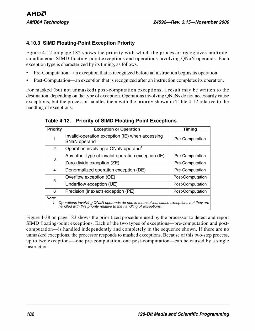
182 128-Bit Media and Scientific Programming
AMD64 Technology 24592—Rev. 3.15—November 2009
4.10.3 SIMD Floating-Point Exception Priority
Figure 4-12 on page 182 shows the priority with which the processor recognizes multiple,simultaneous SIMD floating-point exceptions and operations involving QNaN operands. Eachexception type is characterized by its timing, as follows:
• Pre-Computation—an exception that is recognized before an instruction begins its operation.
• Post-Computation—an exception that is recognized after an instruction completes its operation.
For masked (but not unmasked) post-computation exceptions, a result may be written to thedestination, depending on the type of exception. Operations involving QNaNs do not necessarily causeexceptions, but the processor handles them with the priority shown in Table 4-12 relative to thehandling of exceptions.
Figure 4-38 on page 183 shows the prioritized procedure used by the processor to detect and reportSIMD floating-point exceptions. Each of the two types of exceptions—pre-computation and post-computation—is handled independently and completely in the sequence shown. If there are nounmasked exceptions, the processor responds to masked exceptions. Because of this two-step process,up to two exceptions—one pre-computation, one post-computation—can be caused by a singleinstruction.
Table 4-12. Priority of SIMD Floating-Point Exceptions
Priority Exception or Operation Timing
1Invalid-operation exception (IE) when accessingSNaN operand
Pre-Computation
2 Operation involving a QNaN operand1 —
3Any other type of invalid-operation exception (IE) Pre-Computation
Zero-divide exception (ZE) Pre-Computation
4 Denormalized operation exception (DE) Pre-Computation
5Overflow exception (OE) Post-Computation
Underflow exception (UE) Post-Computation
6 Precision (inexact) exception (PE) Post-Computation
Note:1. Operations involving QNaN operands do not, in themselves, cause exceptions but they are
handled with this priority relative to the handling of exceptions.

128-Bit Media and Scientific Programming 183
24592—Rev. 3.15—November 2009 AMD64 Technology
Figure 4-38. SIMD Floating-Point Detection Process
513-188.epsContinue Execution
Test ForPre-Computation
Exceptions
Set MXCSRException Flags
Yes
No
No
For EachVectorElement
For EachExceptionType
AnyUnmasked Exceptions
?
Test ForPre-Computation
Exceptions
Set MXCSRException Flags
DefaultResponse
Invoke ExceptionService Routine
Yes
For EachVectorElement
For EachExceptionType
AnyUnmasked Exceptions
?
No
YesAnyMasked Exceptions
?
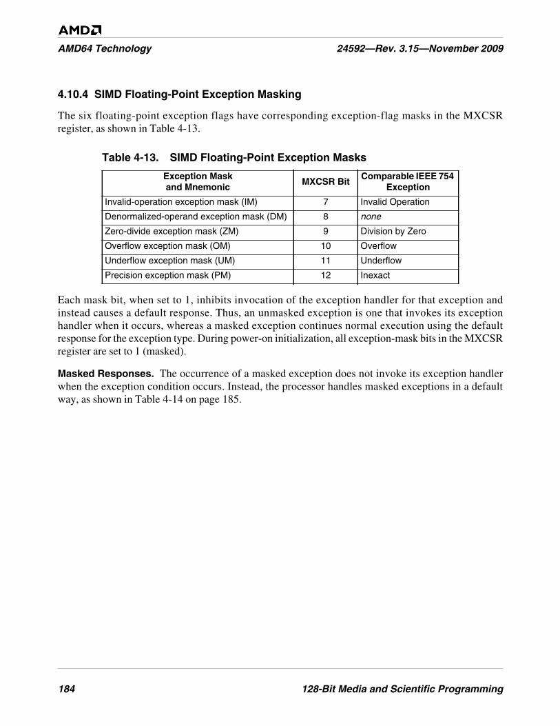
184 128-Bit Media and Scientific Programming
AMD64 Technology 24592—Rev. 3.15—November 2009
4.10.4 SIMD Floating-Point Exception Masking
The six floating-point exception flags have corresponding exception-flag masks in the MXCSRregister, as shown in Table 4-13.
Each mask bit, when set to 1, inhibits invocation of the exception handler for that exception andinstead causes a default response. Thus, an unmasked exception is one that invokes its exceptionhandler when it occurs, whereas a masked exception continues normal execution using the defaultresponse for the exception type. During power-on initialization, all exception-mask bits in the MXCSRregister are set to 1 (masked).
Masked Responses. The occurrence of a masked exception does not invoke its exception handlerwhen the exception condition occurs. Instead, the processor handles masked exceptions in a defaultway, as shown in Table 4-14 on page 185.
Table 4-13. SIMD Floating-Point Exception Masks
Exception Maskand Mnemonic
MXCSR BitComparable IEEE 754
Exception
Invalid-operation exception mask (IM) 7 Invalid Operation
Denormalized-operand exception mask (DM) 8 none
Zero-divide exception mask (ZM) 9 Division by Zero
Overflow exception mask (OM) 10 Overflow
Underflow exception mask (UM) 11 Underflow
Precision exception mask (PM) 12 Inexact
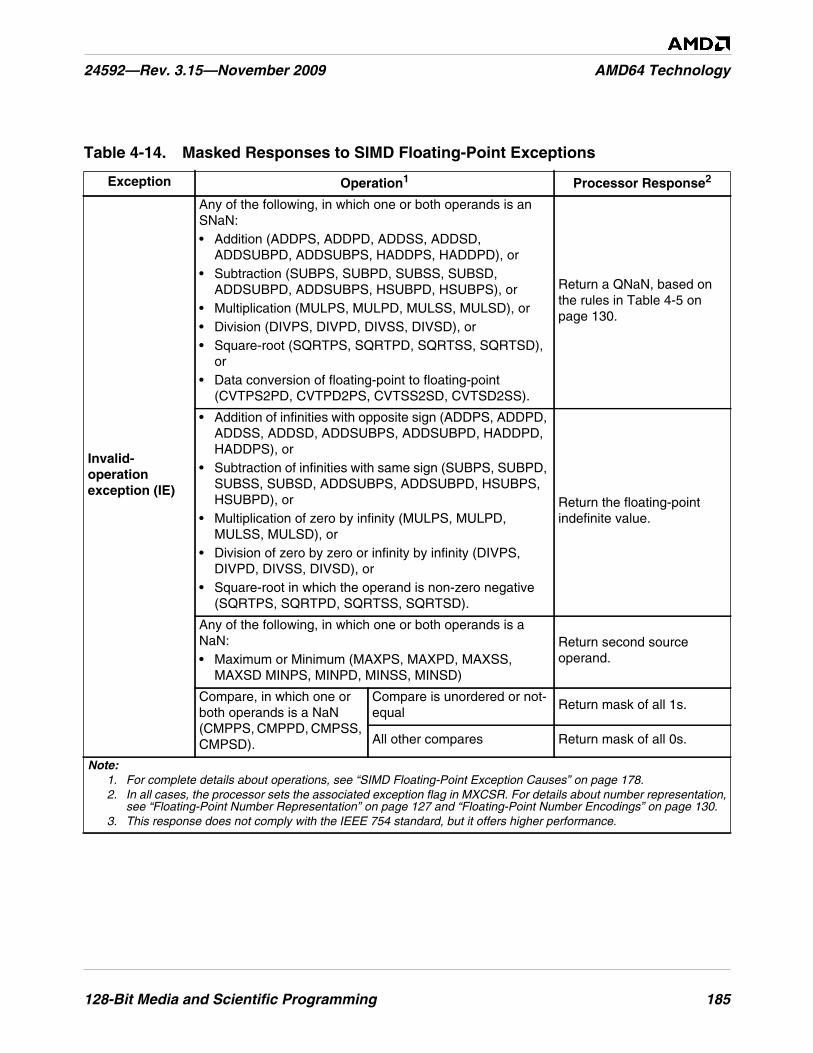
128-Bit Media and Scientific Programming 185
24592—Rev. 3.15—November 2009 AMD64 Technology
Table 4-14. Masked Responses to SIMD Floating-Point Exceptions
Exception Operation1 Processor Response2
Invalid-operationexception (IE)
Any of the following, in which one or both operands is anSNaN:• Addition (ADDPS, ADDPD, ADDSS, ADDSD,
ADDSUBPD, ADDSUBPS, HADDPS, HADDPD), or• Subtraction (SUBPS, SUBPD, SUBSS, SUBSD,
ADDSUBPD, ADDSUBPS, HSUBPD, HSUBPS), or• Multiplication (MULPS, MULPD, MULSS, MULSD), or• Division (DIVPS, DIVPD, DIVSS, DIVSD), or• Square-root (SQRTPS, SQRTPD, SQRTSS, SQRTSD),
or• Data conversion of floating-point to floating-point
(CVTPS2PD, CVTPD2PS, CVTSS2SD, CVTSD2SS).
Return a QNaN, based onthe rules in Table 4-5 onpage 130.
• Addition of infinities with opposite sign (ADDPS, ADDPD,ADDSS, ADDSD, ADDSUBPS, ADDSUBPD, HADDPD,HADDPS), or
• Subtraction of infinities with same sign (SUBPS, SUBPD,SUBSS, SUBSD, ADDSUBPS, ADDSUBPD, HSUBPS,HSUBPD), or
• Multiplication of zero by infinity (MULPS, MULPD,MULSS, MULSD), or
• Division of zero by zero or infinity by infinity (DIVPS,DIVPD, DIVSS, DIVSD), or
• Square-root in which the operand is non-zero negative(SQRTPS, SQRTPD, SQRTSS, SQRTSD).
Return the floating-pointindefinite value.
Any of the following, in which one or both operands is aNaN:• Maximum or Minimum (MAXPS, MAXPD, MAXSS,
MAXSD MINPS, MINPD, MINSS, MINSD)
Return second sourceoperand.
Compare, in which one orboth operands is a NaN(CMPPS, CMPPD, CMPSS,CMPSD).
Compare is unordered or not-equal
Return mask of all 1s.
All other compares Return mask of all 0s.
Note:1. For complete details about operations, see “SIMD Floating-Point Exception Causes” on page 178.2. In all cases, the processor sets the associated exception flag in MXCSR. For details about number representation,
see “Floating-Point Number Representation” on page 127 and “Floating-Point Number Encodings” on page 130.3. This response does not comply with the IEEE 754 standard, but it offers higher performance.
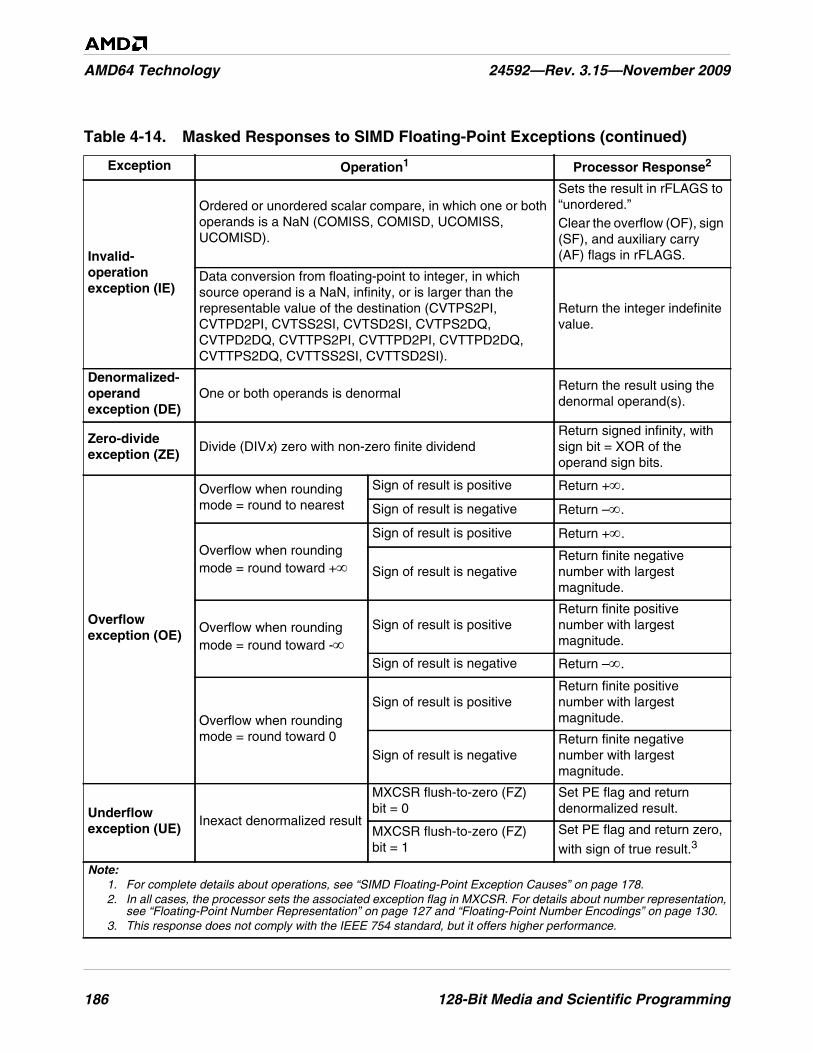
186 128-Bit Media and Scientific Programming
AMD64 Technology 24592—Rev. 3.15—November 2009
Invalid-operationexception (IE)
Ordered or unordered scalar compare, in which one or bothoperands is a NaN (COMISS, COMISD, UCOMISS,UCOMISD).
Sets the result in rFLAGS to“unordered.”Clear the overflow (OF), sign(SF), and auxiliary carry(AF) flags in rFLAGS.
Data conversion from floating-point to integer, in whichsource operand is a NaN, infinity, or is larger than therepresentable value of the destination (CVTPS2PI,CVTPD2PI, CVTSS2SI, CVTSD2SI, CVTPS2DQ,CVTPD2DQ, CVTTPS2PI, CVTTPD2PI, CVTTPD2DQ,CVTTPS2DQ, CVTTSS2SI, CVTTSD2SI).
Return the integer indefinitevalue.
Denormalized-operandexception (DE)
One or both operands is denormalReturn the result using thedenormal operand(s).
Zero-divideexception (ZE)
Divide (DIVx) zero with non-zero finite dividendReturn signed infinity, withsign bit = XOR of theoperand sign bits.
Overflowexception (OE)
Overflow when roundingmode = round to nearest
Sign of result is positive Return +∞.
Sign of result is negative Return –∞.
Overflow when roundingmode = round toward +∞
Sign of result is positive Return +∞.
Sign of result is negativeReturn finite negativenumber with largestmagnitude.
Overflow when roundingmode = round toward -∞
Sign of result is positiveReturn finite positivenumber with largestmagnitude.
Sign of result is negative Return –∞.
Overflow when roundingmode = round toward 0
Sign of result is positiveReturn finite positivenumber with largestmagnitude.
Sign of result is negativeReturn finite negativenumber with largestmagnitude.
Underflowexception (UE)
Inexact denormalized result
MXCSR flush-to-zero (FZ)bit = 0
Set PE flag and returndenormalized result.
MXCSR flush-to-zero (FZ)bit = 1
Set PE flag and return zero,
with sign of true result.3
Table 4-14. Masked Responses to SIMD Floating-Point Exceptions (continued)
Exception Operation1 Processor Response2
Note:1. For complete details about operations, see “SIMD Floating-Point Exception Causes” on page 178.2. In all cases, the processor sets the associated exception flag in MXCSR. For details about number representation,
see “Floating-Point Number Representation” on page 127 and “Floating-Point Number Encodings” on page 130.3. This response does not comply with the IEEE 754 standard, but it offers higher performance.
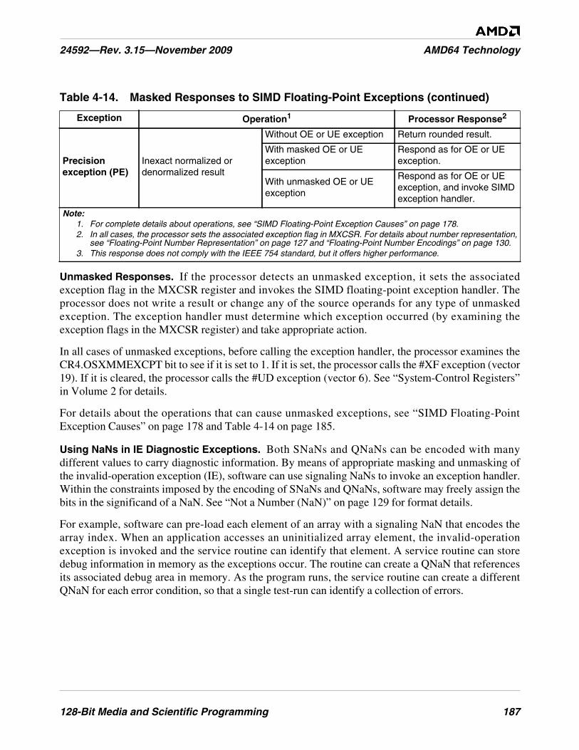
128-Bit Media and Scientific Programming 187
24592—Rev. 3.15—November 2009 AMD64 Technology
Unmasked Responses. If the processor detects an unmasked exception, it sets the associatedexception flag in the MXCSR register and invokes the SIMD floating-point exception handler. Theprocessor does not write a result or change any of the source operands for any type of unmaskedexception. The exception handler must determine which exception occurred (by examining theexception flags in the MXCSR register) and take appropriate action.
In all cases of unmasked exceptions, before calling the exception handler, the processor examines theCR4.OSXMMEXCPT bit to see if it is set to 1. If it is set, the processor calls the #XF exception (vector19). If it is cleared, the processor calls the #UD exception (vector 6). See “System-Control Registers”in Volume 2 for details.
For details about the operations that can cause unmasked exceptions, see “SIMD Floating-PointException Causes” on page 178 and Table 4-14 on page 185.
Using NaNs in IE Diagnostic Exceptions. Both SNaNs and QNaNs can be encoded with manydifferent values to carry diagnostic information. By means of appropriate masking and unmasking ofthe invalid-operation exception (IE), software can use signaling NaNs to invoke an exception handler.Within the constraints imposed by the encoding of SNaNs and QNaNs, software may freely assign thebits in the significand of a NaN. See “Not a Number (NaN)” on page 129 for format details.
For example, software can pre-load each element of an array with a signaling NaN that encodes thearray index. When an application accesses an uninitialized array element, the invalid-operationexception is invoked and the service routine can identify that element. A service routine can storedebug information in memory as the exceptions occur. The routine can create a QNaN that referencesits associated debug area in memory. As the program runs, the service routine can create a differentQNaN for each error condition, so that a single test-run can identify a collection of errors.
Precisionexception (PE)
Inexact normalized ordenormalized result
Without OE or UE exception Return rounded result.
With masked OE or UEexception
Respond as for OE or UEexception.
With unmasked OE or UEexception
Respond as for OE or UEexception, and invoke SIMDexception handler.
Table 4-14. Masked Responses to SIMD Floating-Point Exceptions (continued)
Exception Operation1 Processor Response2
Note:1. For complete details about operations, see “SIMD Floating-Point Exception Causes” on page 178.2. In all cases, the processor sets the associated exception flag in MXCSR. For details about number representation,
see “Floating-Point Number Representation” on page 127 and “Floating-Point Number Encodings” on page 130.3. This response does not comply with the IEEE 754 standard, but it offers higher performance.
188 128-Bit Media and Scientific Programming
AMD64 Technology 24592—Rev. 3.15—November 2009
4.11 Saving, Clearing, and Passing State
4.11.1 Saving and Restoring State
In general, system software should save and restore 128-bit media state between task switches or otherinterventions in the execution of 128-bit media procedures. Virtually all modern operating systemsrunning on x86 processors implement preemptive multitasking that handle saving and restoring ofstate across task switches, independent of hardware task-switch support. However, applicationprocedures are also free to save and restore 128-bit media state at any time they deem useful.
Software running at any privilege level may save and restore 128-bit media state by executing theFXSAVE instruction, which saves not only 128-bit media state but also x87 floating-point state.Alternatively, software may use multiple move instructions for saving only the contents of selected128-bit media data registers, or the STMXCSR instruction for saving the MXCSR register state. Fordetails, see “Save and Restore State” on page 156.
4.11.2 Parameter Passing
128-bit media procedures can use MOVx instructions to pass data to other such procedures. This canbe done directly, via the XMM registers, or indirectly by storing data on the procedure stack. Whenstoring to the stack, software should use the rSP register for the memory address and, after the save,explicitly decrement rSP by 16 for each 128-bit XMM register parameter stored on the stack.Likewise, to load a 128-bit XMM register from the stack, software should increment rSP by 16 afterthe load. There is a choice of MOVx instructions designed for aligned and unaligned moves, asdescribed in “Data Transfer” on page 135 and “Data Transfer” on page 157.
The processor does not check the data type of instruction operands prior to executing instructions. Itonly checks them at the point of execution. For example, if the processor executes an arithmeticinstruction that takes double-precision operands but is provided with single-precision operands byMOVx instructions, the processor will first convert the operands from single precision to doubleprecision prior to executing the arithmetic operation, and the result will be correct. However, therequired conversion may cause degradation of performance.
Because of this possibility of data-type mismatching between MOVx instructions used to passparameters and the instructions in the called procedure that subsequently operate on the moved data,the calling procedure should save its own state prior to the call. The called procedure cannot determinethe caller’s data types, and thus it cannot optimize its choice of instructions for storing a caller’s state.
For further information, see the software optimization documentation for particular hardwareimplementations.
4.11.3 Accessing Operands in MMX™ Registers
Software may freely mix 128-bit media instructions (integer or floating-point) with 64-bit mediainstructions (integer or floating-point) and general-purpose instructions in a single procedure. Thereare no restrictions on transitioning from 128-bit media procedures to x87 procedures, except when a
128-Bit Media and Scientific Programming 189
24592—Rev. 3.15—November 2009 AMD64 Technology
128-bit media procedure accesses an MMX register by means of a data-transfer or data-conversioninstruction.
In such cases, software should separate such procedures or dynamic link libraries (DLLs) from x87floating-point procedures or DLLs by clearing the MMX state with the EMMS instruction, asdescribed in “Exit Media State” on page 209. For further details, see “Mixing Media Code with x87Code” on page 233.
4.12 Performance Considerations
In addition to typical code optimization techniques, such as those affecting loops and the inlining offunction calls, the following considerations may help improve the performance of applicationprograms written with 128-bit media instructions.
These are implementation-independent performance considerations. Other considerations depend onthe hardware implementation. For information about such implementation-dependent considerationsand for more information about application performance in general, see the data sheets and thesoftware-optimization guides relating to particular hardware implementations.
4.12.1 Use Small Operand Sizes
The performance advantages available with 128-bit media operations is to some extent a function ofthe data sizes operated upon. The smaller the data size, the more data elements that can be packed intosingle 128-bit vectors. The parallelism of computation increases as the number of elements per vectorincreases.
4.12.2 Reorganize Data for Parallel Operations
Much of the performance benefit from the 128-bit media instructions comes from the parallelisminherent in vector operations. It can be advantageous to reorganize data before performing arithmeticoperations so that its layout after reorganization maximizes the parallelism of the arithmeticoperations.
The speed of memory access is particularly important for certain types of computation, such asgraphics rendering, that depend on the regularity and locality of data-memory accesses. For example,in matrix operations, performance is high when operating on the rows of the matrix, because row bytesare contiguous in memory, but lower when operating on the columns of the matrix, because columnbytes are not contiguous in memory and accessing them can result in cache misses. To improveperformance for operations on such columns, the matrix should first be transposed. Suchtranspositions can, for example, be done using a sequence of unpacking or shuffle instructions.
4.12.3 Remove Branches
Branch can be replaced with 128-bit media instructions that simulate predicated execution orconditional moves, as described in “Branch Removal” on page 114. The branch can be replaced with
190 128-Bit Media and Scientific Programming
AMD64 Technology 24592—Rev. 3.15—November 2009
128-bit media instructions that simulate predicated execution or conditional moves. Figure 4-10 onpage 115 shows an example of a non-branching sequence that implements a two-way multiplexer.
Where possible, break long dependency chains into several shorter dependency chains that can beexecuted in parallel. This is especially important for floating-point instructions because of their longerlatencies.
4.12.4 Use Streaming Stores
The MOVNTDQ, MOVNTDQA and MASKMOVDQU instructions store streaming (non-temporal)data to memory. These instructions indicate to the processor that the data they reference will be usedonly once and is therefore not subject to cache-related overhead (such as write-allocation). A typicalcase benefitting from streaming stores occurs when data written by the processor is never read by theprocessor, such as data written to a graphics frame buffer.
4.12.5 Align Data
Data alignment is particularly important for performance when data written by one instruction is readby a subsequent instruction soon after the write, or when accessing streaming (non-temporal) data.These cases may occur frequently in 128-bit media procedures.
Accesses to data stored at unaligned locations may benefit from on-the-fly software alignment or fromrepetition of data at different alignment boundaries, as required by different loops that process the data.
4.12.6 Organize Data for Cacheability
Pack small data structures into cache-line-size blocks. Organize frequently accessed constants andcoefficients into cache-line-size blocks and prefetch them. Procedures that access data arranged inmemory-bus-sized blocks, or memory-burst-sized blocks, can make optimum use of the availablememory bandwidth.
For data that will be used only once in a procedure, consider using non-cacheable memory. Accesses tosuch memory are not burdened by the overhead of cache protocols.
4.12.7 Prefetch Data
Media applications typically operate on large data sets. Because of this, they make intensive use of thememory bus. Memory latency can be substantially reduced—especially for data that will be used onlyonce—by prefetching such data into various levels of the cache hierarchy. Software can use thePREFETCHx instructions very effectively in such cases, as described in “Cache and MemoryManagement” on page 66.
Some of the best places to use prefetch instructions are inside loops that process large amounts of data.If the loop goes through less than one cache line of data per iteration, partially unroll the loop. Try touse virtually all of the prefetched data. This usually requires unit-stride memory accesses—those inwhich all accesses are to contiguous memory locations. Exactly one PREFETCHx instruction per
128-Bit Media and Scientific Programming 191
24592—Rev. 3.15—November 2009 AMD64 Technology
cache line must be used. For further details, see the Optimization Guide for AMD Athlon™ 64 andAMD Opteron™ Processors, order# 25112.
4.12.8 Use 128-Bit Media Code for Moving Data
Movements of data between memory, GPR, XMM, and MMX registers can take advantage of theparallel vector operations supported by the 128-bit media MOVx instructions. Figure 4-6 on page 111illustrates the range of move operations available.
4.12.9 Retain Intermediate Results in XMM Registers
Keep intermediate results in the XMM registers as much as possible, especially if the intermediateresults are used shortly after they have been produced. Avoid spilling intermediate results to memoryand reusing them shortly thereafter. In 64-bit mode, the architecture’s 16 XMM registers offer twicethe number of legacy XMM registers.
4.12.10 Replace GPR Code with 128-Bit Media Code.
In 64-bit mode, the AMD64 architecture provides twice the number of general-purpose registers(GPRs) as the legacy x86 architecture, thereby reducing potential pressure on GPRs. Nevertheless,general-purpose instructions do not operate in parallel on vectors of elements, as do 128-bit mediainstructions. Thus, 128-bit media code supports parallel operations and can perform better withalgorithms and data that are organized for parallel operations.
4.12.11 Replace x87 Code with 128-Bit Media Code
One of the most useful advantages of 128-bit media instructions is the ability to intermix integer andfloating-point instructions in the same procedure, using a register set that is separate from the GPR,MMX, and x87 register sets. Code written with 128-bit media floating-point instructions can operatein parallel on four times as many single-precision floating-point operands as can x87 floating-pointcode. This achieves potentially four times the computational work of x87 instructions that take single-precision operands. Also, the higher density of 128-bit media floating-point operands may make itpossible to remove local temporary variables that would otherwise be needed in x87 floating-pointcode. 128-bit media code is also easier to write than x87 floating-point code, because the XMMregister file is flat, rather than stack-oriented, and in 64-bit mode there are twice the number of XMMregisters as x87 registers. Moreover, when integer and floating-point instructions must be usedtogether, 128-bit media floating-point instructions avoid the potential need to save and restore statebetween integer operations and floating-point procedures.
192 128-Bit Media and Scientific Programming
AMD64 Technology 24592—Rev. 3.15—November 2009
64-Bit Media Programming 193
24592—Rev. 3.15—November 2009 AMD64 Technology
5 64-Bit Media Programming
This chapter describes the 64-bit media programming model. This model includes all instructions thataccess the MMX™ registers, including the MMX and 3DNow!™ instructions, as well as some SSEand SSE2 instructions.
The 64-bit media instructions perform integer and floating-point operations primarily on vectoroperands (a few of the instructions take scalar operands). The MMX integer operations producesigned, unsigned, and/or saturating results. The 3DNow! floating-point operations take single-precision operands and produce saturating results without generating floating-point exceptions. Theinstructions that take vector operands can speed up certain types of procedures by significant factors,depending on data-element size and the regularity and locality of data accesses to memory.
The term 64-bit is used in two different contexts within the AMD64 architecture: the 64-bit mediainstructions, described in this chapter, and the 64-bit operating mode, described in “64-Bit Mode” onpage 6.
5.1 Origins
The 64-bit media instructions were introduced in the following extensions to the legacy x86architecture:
• MMX Instructions—These are primarily integer instructions that take vector operands in 64-bitMMX registers or memory locations.
• 3DNow! Instructions—These are primarily floating-point instructions, most of which take vectoroperands in MMX registers or memory locations.
• SSE, SSE2, SSE3, and SSE4A Instructions—These are the streaming SIMD extensions (SSE),SSE2, SSE3, and SSE4A instructions. Some of them perform conversions between operands in the64-bit MMX register set and other register sets.
For details on the extension-set origin of each instruction, see “Instruction Subsets vs. CPUID FeatureSets” in Volume 3.
5.2 Compatibility
64-bit media instructions can be executed in any of the architecture’s operating modes. Existing MMXand 3DNow! binary programs run in legacy and compatibility modes without modification. Thesupport provided by the AMD64 architecture for such binaries is identical to that provided by legacyx86 architectures.
To run in 64-bit mode, 64-bit media programs must be recompiled. The recompilation has no sideeffects on such programs, other than to make available the extended general-purpose registers and 64-bit virtual address space.
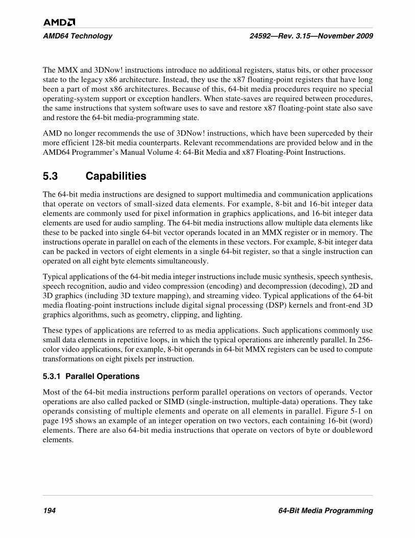
194 64-Bit Media Programming
AMD64 Technology 24592—Rev. 3.15—November 2009
The MMX and 3DNow! instructions introduce no additional registers, status bits, or other processorstate to the legacy x86 architecture. Instead, they use the x87 floating-point registers that have longbeen a part of most x86 architectures. Because of this, 64-bit media procedures require no specialoperating-system support or exception handlers. When state-saves are required between procedures,the same instructions that system software uses to save and restore x87 floating-point state also saveand restore the 64-bit media-programming state.
AMD no longer recommends the use of 3DNow! instructions, which have been superceded by theirmore efficient 128-bit media counterparts. Relevant recommendations are provided below and in theAMD64 Programmer’s Manual Volume 4: 64-Bit Media and x87 Floating-Point Instructions.
5.3 Capabilities
The 64-bit media instructions are designed to support multimedia and communication applicationsthat operate on vectors of small-sized data elements. For example, 8-bit and 16-bit integer dataelements are commonly used for pixel information in graphics applications, and 16-bit integer dataelements are used for audio sampling. The 64-bit media instructions allow multiple data elements likethese to be packed into single 64-bit vector operands located in an MMX register or in memory. Theinstructions operate in parallel on each of the elements in these vectors. For example, 8-bit integer datacan be packed in vectors of eight elements in a single 64-bit register, so that a single instruction canoperated on all eight byte elements simultaneously.
Typical applications of the 64-bit media integer instructions include music synthesis, speech synthesis,speech recognition, audio and video compression (encoding) and decompression (decoding), 2D and3D graphics (including 3D texture mapping), and streaming video. Typical applications of the 64-bitmedia floating-point instructions include digital signal processing (DSP) kernels and front-end 3Dgraphics algorithms, such as geometry, clipping, and lighting.
These types of applications are referred to as media applications. Such applications commonly usesmall data elements in repetitive loops, in which the typical operations are inherently parallel. In 256-color video applications, for example, 8-bit operands in 64-bit MMX registers can be used to computetransformations on eight pixels per instruction.
5.3.1 Parallel Operations
Most of the 64-bit media instructions perform parallel operations on vectors of operands. Vectoroperations are also called packed or SIMD (single-instruction, multiple-data) operations. They takeoperands consisting of multiple elements and operate on all elements in parallel. Figure 5-1 onpage 195 shows an example of an integer operation on two vectors, each containing 16-bit (word)elements. There are also 64-bit media instructions that operate on vectors of byte or doublewordelements.
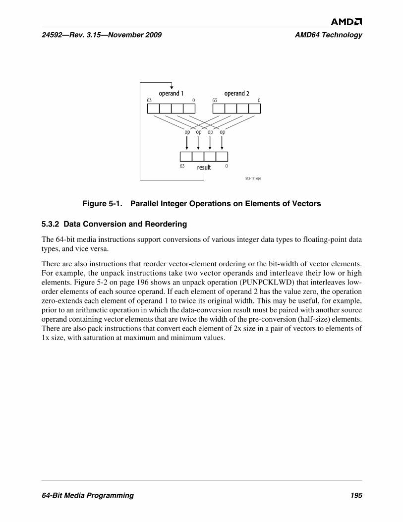
64-Bit Media Programming 195
24592—Rev. 3.15—November 2009 AMD64 Technology
Figure 5-1. Parallel Integer Operations on Elements of Vectors
5.3.2 Data Conversion and Reordering
The 64-bit media instructions support conversions of various integer data types to floating-point datatypes, and vice versa.
There are also instructions that reorder vector-element ordering or the bit-width of vector elements.For example, the unpack instructions take two vector operands and interleave their low or highelements. Figure 5-2 on page 196 shows an unpack operation (PUNPCKLWD) that interleaves low-order elements of each source operand. If each element of operand 2 has the value zero, the operationzero-extends each element of operand 1 to twice its original width. This may be useful, for example,prior to an arithmetic operation in which the data-conversion result must be paired with another sourceoperand containing vector elements that are twice the width of the pre-conversion (half-size) elements.There are also pack instructions that convert each element of 2x size in a pair of vectors to elements of1x size, with saturation at maximum and minimum values.
513-121.eps
operand 1
result
63 0
63 0
operand 263 0
op op op op
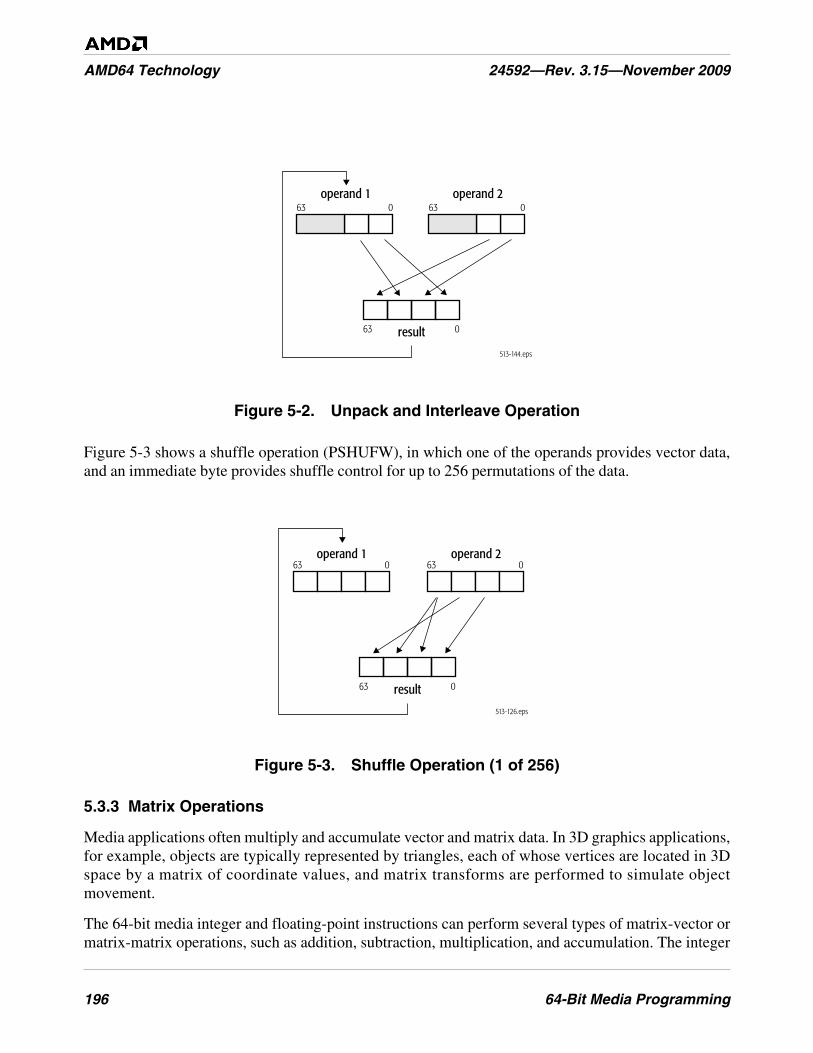
196 64-Bit Media Programming
AMD64 Technology 24592—Rev. 3.15—November 2009
Figure 5-2. Unpack and Interleave Operation
Figure 5-3 shows a shuffle operation (PSHUFW), in which one of the operands provides vector data,and an immediate byte provides shuffle control for up to 256 permutations of the data.
Figure 5-3. Shuffle Operation (1 of 256)
5.3.3 Matrix Operations
Media applications often multiply and accumulate vector and matrix data. In 3D graphics applications,for example, objects are typically represented by triangles, each of whose vertices are located in 3Dspace by a matrix of coordinate values, and matrix transforms are performed to simulate objectmovement.
The 64-bit media integer and floating-point instructions can perform several types of matrix-vector ormatrix-matrix operations, such as addition, subtraction, multiplication, and accumulation. The integer
513-144.eps
operand 1
result
63 0
63 0
operand 263 0
513-126.eps
operand 2operand 1
result
63 0
63 0
63 0
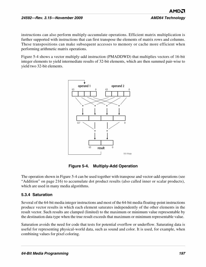
64-Bit Media Programming 197
24592—Rev. 3.15—November 2009 AMD64 Technology
instructions can also perform multiply-accumulate operations. Efficient matrix multiplication isfurther supported with instructions that can first transpose the elements of matrix rows and columns.These transpositions can make subsequent accesses to memory or cache more efficient whenperforming arithmetic matrix operations.
Figure 5-4 shows a vector multiply-add instruction (PMADDWD) that multiplies vectors of 16-bitinteger elements to yield intermediate results of 32-bit elements, which are then summed pair-wise toyield two 32-bit elements.
Figure 5-4. Multiply-Add Operation
The operation shown in Figure 5-4 can be used together with transpose and vector-add operations (see“Addition” on page 216) to accumulate dot product results (also called inner or scalar products),which are used in many media algorithms.
5.3.4 Saturation
Several of the 64-bit media integer instructions and most of the 64-bit media floating-point instructionsproduce vector results in which each element saturates independently of the other elements in theresult vector. Such results are clamped (limited) to the maximum or minimum value representable bythe destination data type when the true result exceeds that maximum or minimum representable value.
Saturation avoids the need for code that tests for potential overflow or underflow. Saturating data isuseful for representing physical-world data, such as sound and color. It is used, for example, whencombining values for pixel coloring.
513-119.eps
operand 1
result
63 0
63 0
operand 263 0
127 0
*
+ +
***
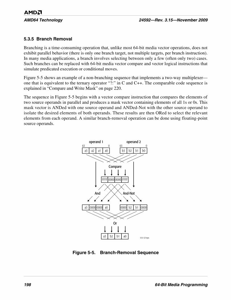
198 64-Bit Media Programming
AMD64 Technology 24592—Rev. 3.15—November 2009
5.3.5 Branch Removal
Branching is a time-consuming operation that, unlike most 64-bit media vector operations, does notexhibit parallel behavior (there is only one branch target, not multiple targets, per branch instruction).In many media applications, a branch involves selecting between only a few (often only two) cases.Such branches can be replaced with 64-bit media vector compare and vector logical instructions thatsimulate predicated execution or conditional moves.
Figure 5-5 shows an example of a non-branching sequence that implements a two-way multiplexer—one that is equivalent to the ternary operator “?:” in C and C++. The comparable code sequence isexplained in “Compare and Write Mask” on page 220.
The sequence in Figure 5-5 begins with a vector compare instruction that compares the elements oftwo source operands in parallel and produces a mask vector containing elements of all 1s or 0s. Thismask vector is ANDed with one source operand and ANDed-Not with the other source operand toisolate the desired elements of both operands. These results are then ORed to select the relevantelements from each operand. A similar branch-removal operation can be done using floating-pointsource operands.
Figure 5-5. Branch-Removal Sequence
513-127.eps
operand 163 0
operand 263 0
FFFF 0000 0000 FFFF
a3 a2 a1 a0 b3 b2 b1 b0
a3 0000 0000 a0 0000 b2 b1 0000
And And-Not
Compare
a3 b2 b1 a0
Or
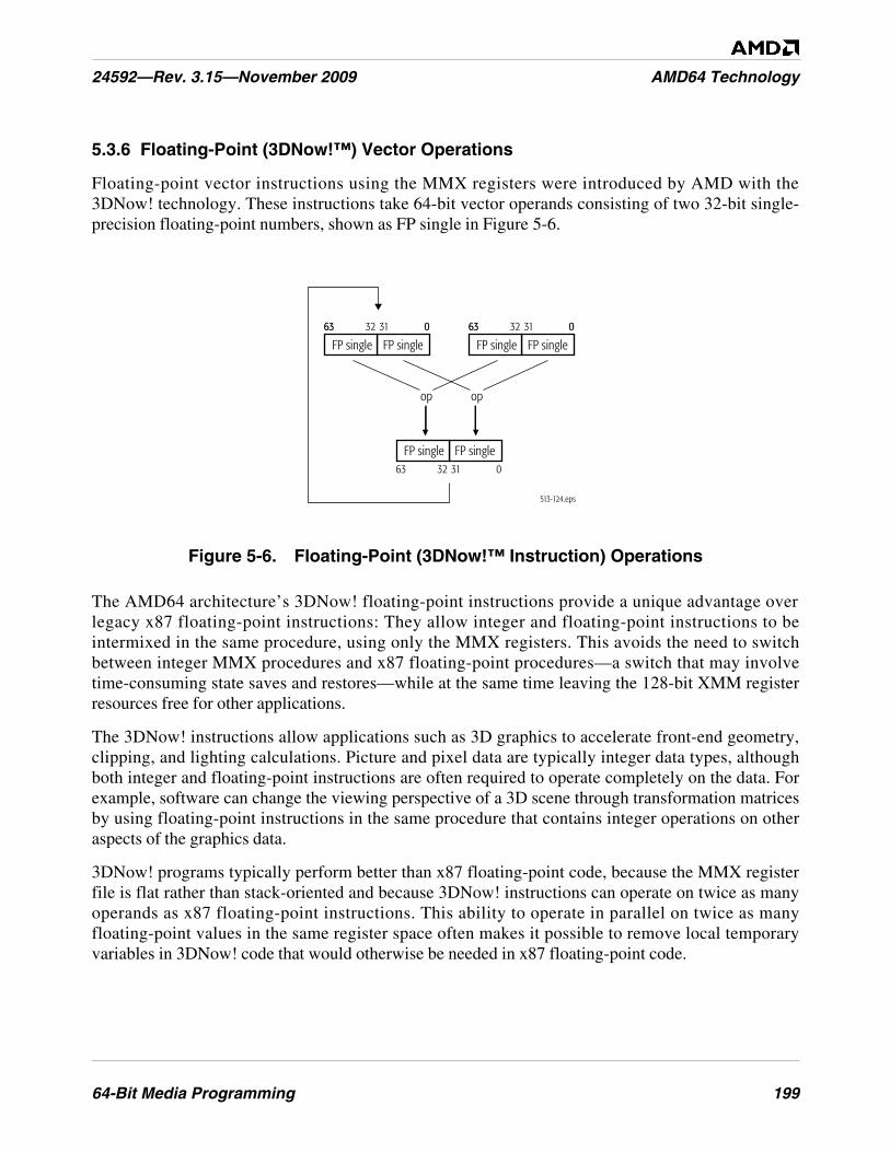
64-Bit Media Programming 199
24592—Rev. 3.15—November 2009 AMD64 Technology
5.3.6 Floating-Point (3DNow!™) Vector Operations
Floating-point vector instructions using the MMX registers were introduced by AMD with the3DNow! technology. These instructions take 64-bit vector operands consisting of two 32-bit single-precision floating-point numbers, shown as FP single in Figure 5-6.
Figure 5-6. Floating-Point (3DNow!™ Instruction) Operations
The AMD64 architecture’s 3DNow! floating-point instructions provide a unique advantage overlegacy x87 floating-point instructions: They allow integer and floating-point instructions to beintermixed in the same procedure, using only the MMX registers. This avoids the need to switchbetween integer MMX procedures and x87 floating-point procedures—a switch that may involvetime-consuming state saves and restores—while at the same time leaving the 128-bit XMM registerresources free for other applications.
The 3DNow! instructions allow applications such as 3D graphics to accelerate front-end geometry,clipping, and lighting calculations. Picture and pixel data are typically integer data types, althoughboth integer and floating-point instructions are often required to operate completely on the data. Forexample, software can change the viewing perspective of a 3D scene through transformation matricesby using floating-point instructions in the same procedure that contains integer operations on otheraspects of the graphics data.
3DNow! programs typically perform better than x87 floating-point code, because the MMX registerfile is flat rather than stack-oriented and because 3DNow! instructions can operate on twice as manyoperands as x87 floating-point instructions. This ability to operate in parallel on twice as manyfloating-point values in the same register space often makes it possible to remove local temporaryvariables in 3DNow! code that would otherwise be needed in x87 floating-point code.
63 31 032
FP single FP single63 31 032
FP single FP single
63 31 032
FP single FP single
513-124.eps
63 0 63 0
op op
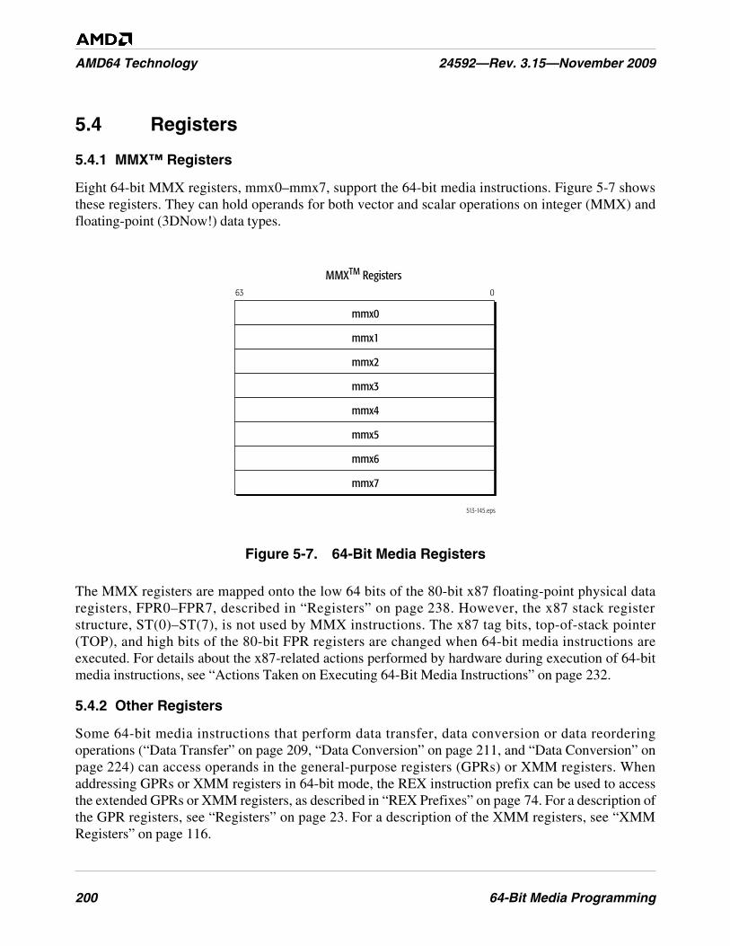
200 64-Bit Media Programming
AMD64 Technology 24592—Rev. 3.15—November 2009
5.4 Registers
5.4.1 MMX™ Registers
Eight 64-bit MMX registers, mmx0–mmx7, support the 64-bit media instructions. Figure 5-7 showsthese registers. They can hold operands for both vector and scalar operations on integer (MMX) andfloating-point (3DNow!) data types.
Figure 5-7. 64-Bit Media Registers
The MMX registers are mapped onto the low 64 bits of the 80-bit x87 floating-point physical dataregisters, FPR0–FPR7, described in “Registers” on page 238. However, the x87 stack registerstructure, ST(0)–ST(7), is not used by MMX instructions. The x87 tag bits, top-of-stack pointer(TOP), and high bits of the 80-bit FPR registers are changed when 64-bit media instructions areexecuted. For details about the x87-related actions performed by hardware during execution of 64-bitmedia instructions, see “Actions Taken on Executing 64-Bit Media Instructions” on page 232.
5.4.2 Other Registers
Some 64-bit media instructions that perform data transfer, data conversion or data reorderingoperations (“Data Transfer” on page 209, “Data Conversion” on page 211, and “Data Conversion” onpage 224) can access operands in the general-purpose registers (GPRs) or XMM registers. Whenaddressing GPRs or XMM registers in 64-bit mode, the REX instruction prefix can be used to accessthe extended GPRs or XMM registers, as described in “REX Prefixes” on page 74. For a description ofthe GPR registers, see “Registers” on page 23. For a description of the XMM registers, see “XMMRegisters” on page 116.
513-145.eps
MMXTM Registers63 0
mmx0
mmx1
mmx2
mmx3
mmx4
mmx5
mmx6
mmx7
64-Bit Media Programming 201
24592—Rev. 3.15—November 2009 AMD64 Technology
5.5 Operands
Operands for a 64-bit media instruction are either referenced by the instruction's opcode or included asan immediate value in the instruction encoding. Depending on the instruction, referenced operands canbe located in registers or memory. The data types of these operands include vector and scalar integer,and vector floating-point.
5.5.1 Data Types
Figure 5-8 on page 202 shows the register images of the 64-bit media data types. These data types canbe interpreted by instruction syntax and/or the software context as one of the following types of values:
• Vector (packed) single-precision (32-bit) floating-point numbers.
• Vector (packed) signed (two's-complement) integers.
• Vector (packed) unsigned integers.
• Scalar signed (two's-complement) integers.
• Scalar unsigned integers.
Hardware does not check or enforce the data types for instructions. Software is responsible forensuring that each operand for an instruction is of the correct data type. Software can interpret the datatypes in ways other than those shown in Figure 5-8 on page 202—such as bit fields or fractionalnumbers—but the 64-bit media instructions do not directly support such interpretations and softwaremust handle them entirely on its own.
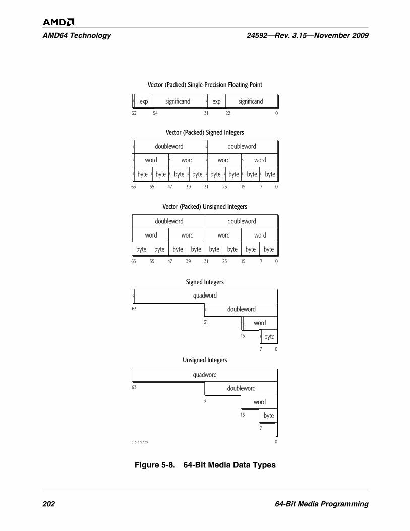
202 64-Bit Media Programming
AMD64 Technology 24592—Rev. 3.15—November 2009
Figure 5-8. 64-Bit Media Data Types
ss ss
ssss
ss
ssssssss
ssss
ss
ssssssss
513-319.eps
715233139475563 0
bytebytebytebytebytebytebytebyte
31 2263 54 0
Vector (Packed) Single-Precision Floating-Point
Vector (Packed) Unsigned Integers
715233139475563 0
doubleworddoubleword
wordwordwordword
doubleworddoubleword
wordwordwordword
bytebytebytebytebytebytebytebyte
Vector (Packed) Signed Integers
significandexpsignificandexp
63
31
15
7 0
s
s
s
s
Unsigned Integers
Signed Integers
quadword
doubleword
word
byte
63
31
15
7
0
quadword
doubleword
word
byte
64-Bit Media Programming 203
24592—Rev. 3.15—November 2009 AMD64 Technology
5.5.2 Operand Sizes and Overrides
Operand sizes for 64-bit media instructions are determined by instruction opcodes. Some of theseopcodes include an operand-size override prefix, but this prefix acts in a special way to modify theopcode and is considered an integral part of the opcode. The general use of the 66h operand-sizeoverride prefix described in “Instruction Prefixes” on page 71 does not apply to 64-bit mediainstructions.
For details on the use of operand-size override prefixes in 64-bit media instructions, see the opcodes in“64-Bit Media Instruction Reference” in Volume 5.
5.5.3 Operand Addressing
Depending on the 64-bit media instruction, referenced operands may be in registers or memory.
Register Operands. Most 64-bit media instructions can access source and destination operandslocated in MMX registers. A few of these instructions access the XMM or GPR registers. Whenaddressing GPR or XMM registers in 64-bit mode, the REX instruction prefix can be used to accessthe extended GPR or XMM registers, as described in “Instruction Prefixes” on page 228.
The 64-bit media instructions do not access the rFLAGS register, and none of the bits in that registerare affected by execution of the 64-bit media instructions.
Memory Operands. Most 64-bit media instructions can read memory for source operands, and a fewof the instructions can write results to memory. “Memory Addressing” on page 14, describes thegeneral methods and conditions for addressing memory operands.
Immediate Operands. Immediate operands are used in certain data-conversion and vector-shiftinstructions. Such instructions take 8-bit immediates, which provide control for the operation.
I/O Ports. I/O ports in the I/O address space cannot be directly addressed by 64-bit mediainstructions, and although memory-mapped I/O ports can be addressed by such instructions, doing somay produce unpredictable results, depending on the hardware implementation of the architecture. Seethe data sheet or software-optimization documentation for particular hardware implementations.
5.5.4 Data Alignment
Those 64-bit media instructions that access a 128-bit operand in memory incur a general-protectionexception (#GP) if the operand is not aligned to a 16-byte boundary. These instructions include:
• CVTPD2PI—Convert Packed Double-Precision Floating-Point to Packed Doubleword Integers.
• CVTTPD2PI—Convert Packed Double-Precision Floating-Point to Packed Doubleword Integers,Truncated.
• FXRSTOR—Restore XMM, MMX, and x87 State.
• FXSAVE—Save XMM, MMX, and x87 State.
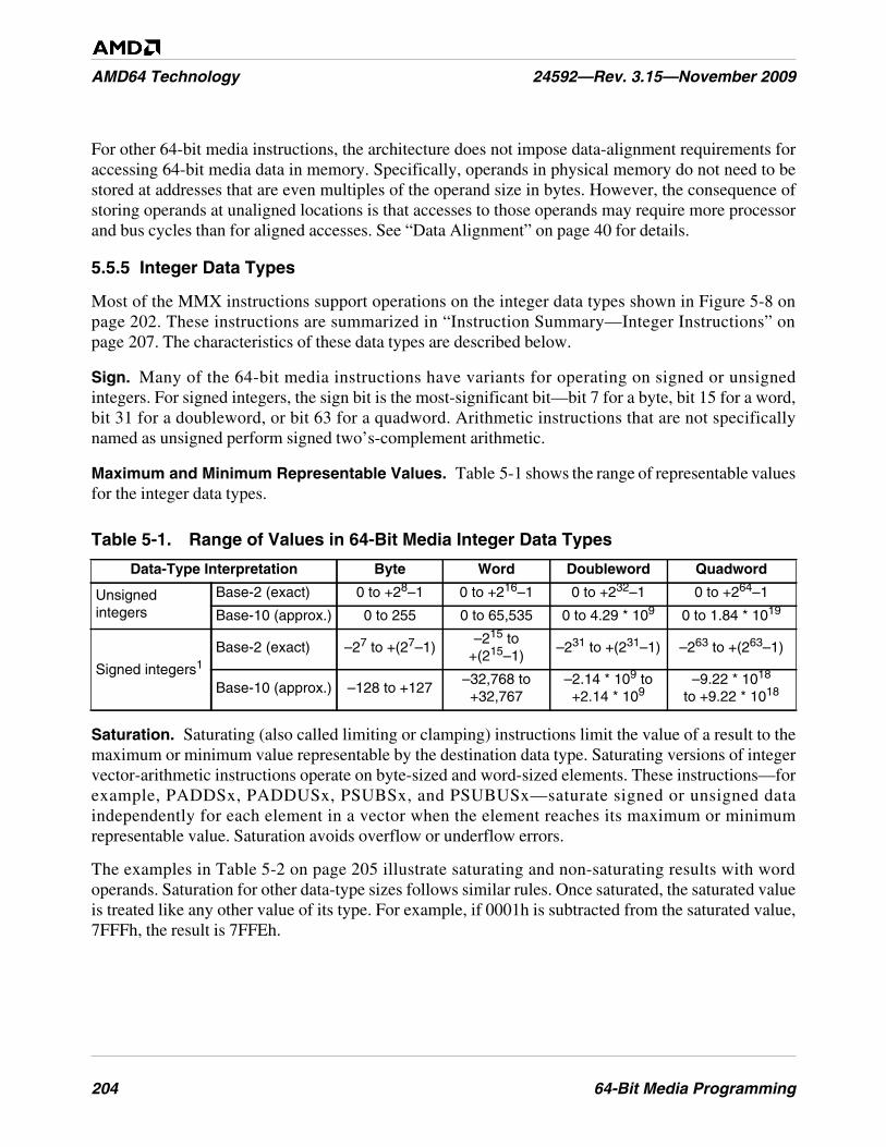
204 64-Bit Media Programming
AMD64 Technology 24592—Rev. 3.15—November 2009
For other 64-bit media instructions, the architecture does not impose data-alignment requirements foraccessing 64-bit media data in memory. Specifically, operands in physical memory do not need to bestored at addresses that are even multiples of the operand size in bytes. However, the consequence ofstoring operands at unaligned locations is that accesses to those operands may require more processorand bus cycles than for aligned accesses. See “Data Alignment” on page 40 for details.
5.5.5 Integer Data Types
Most of the MMX instructions support operations on the integer data types shown in Figure 5-8 onpage 202. These instructions are summarized in “Instruction Summary—Integer Instructions” onpage 207. The characteristics of these data types are described below.
Sign. Many of the 64-bit media instructions have variants for operating on signed or unsignedintegers. For signed integers, the sign bit is the most-significant bit—bit 7 for a byte, bit 15 for a word,bit 31 for a doubleword, or bit 63 for a quadword. Arithmetic instructions that are not specificallynamed as unsigned perform signed two’s-complement arithmetic.
Maximum and Minimum Representable Values. Table 5-1 shows the range of representable valuesfor the integer data types.
Saturation. Saturating (also called limiting or clamping) instructions limit the value of a result to themaximum or minimum value representable by the destination data type. Saturating versions of integervector-arithmetic instructions operate on byte-sized and word-sized elements. These instructions—forexample, PADDSx, PADDUSx, PSUBSx, and PSUBUSx—saturate signed or unsigned dataindependently for each element in a vector when the element reaches its maximum or minimumrepresentable value. Saturation avoids overflow or underflow errors.
The examples in Table 5-2 on page 205 illustrate saturating and non-saturating results with wordoperands. Saturation for other data-type sizes follows similar rules. Once saturated, the saturated valueis treated like any other value of its type. For example, if 0001h is subtracted from the saturated value,7FFFh, the result is 7FFEh.
Table 5-1. Range of Values in 64-Bit Media Integer Data Types
Data-Type Interpretation Byte Word Doubleword Quadword
Unsignedintegers
Base-2 (exact) 0 to +28–1 0 to +216–1 0 to +232–1 0 to +264–1
Base-10 (approx.) 0 to 255 0 to 65,535 0 to 4.29 * 109 0 to 1.84 * 1019
Signed integers1Base-2 (exact) –27 to +(27–1)
–215 to+(215–1)
–231 to +(231–1) –263 to +(263–1)
Base-10 (approx.) –128 to +127–32,768 to+32,767
–2.14 * 109 to+2.14 * 109
–9.22 * 1018
to +9.22 * 1018
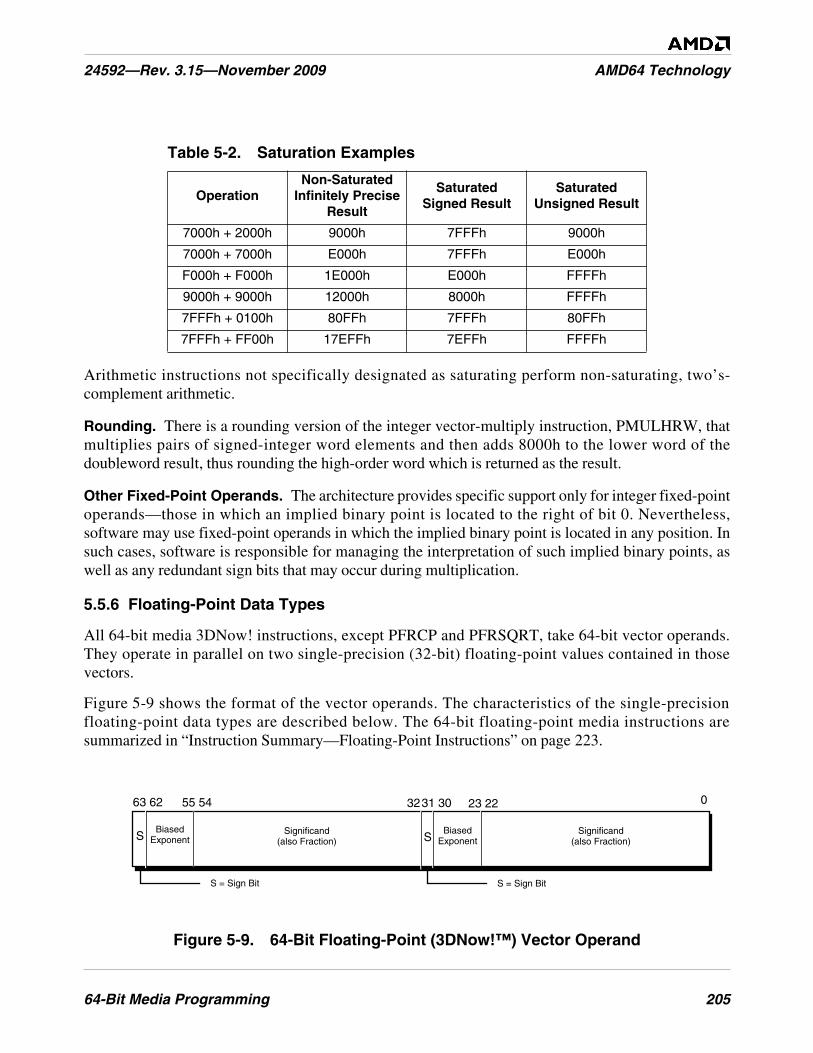
64-Bit Media Programming 205
24592—Rev. 3.15—November 2009 AMD64 Technology
Arithmetic instructions not specifically designated as saturating perform non-saturating, two’s-complement arithmetic.
Rounding. There is a rounding version of the integer vector-multiply instruction, PMULHRW, thatmultiplies pairs of signed-integer word elements and then adds 8000h to the lower word of thedoubleword result, thus rounding the high-order word which is returned as the result.
Other Fixed-Point Operands. The architecture provides specific support only for integer fixed-pointoperands—those in which an implied binary point is located to the right of bit 0. Nevertheless,software may use fixed-point operands in which the implied binary point is located in any position. Insuch cases, software is responsible for managing the interpretation of such implied binary points, aswell as any redundant sign bits that may occur during multiplication.
5.5.6 Floating-Point Data Types
All 64-bit media 3DNow! instructions, except PFRCP and PFRSQRT, take 64-bit vector operands.They operate in parallel on two single-precision (32-bit) floating-point values contained in thosevectors.
Figure 5-9 shows the format of the vector operands. The characteristics of the single-precisionfloating-point data types are described below. The 64-bit floating-point media instructions aresummarized in “Instruction Summary—Floating-Point Instructions” on page 223.
Figure 5-9. 64-Bit Floating-Point (3DNow!™) Vector Operand
Table 5-2. Saturation Examples
OperationNon-Saturated
Infinitely PreciseResult
SaturatedSigned Result
SaturatedUnsigned Result
7000h + 2000h 9000h 7FFFh 9000h
7000h + 7000h E000h 7FFFh E000h
F000h + F000h 1E000h E000h FFFFh
9000h + 9000h 12000h 8000h FFFFh
7FFFh + 0100h 80FFh 7FFFh 80FFh
7FFFh + FF00h 17EFFh 7EFFh FFFFh
63 62 03231 3055 54 23 22
BiasedExponentS Significand
(also Fraction)
S = Sign Bit
BiasedExponentS
S = Sign Bit
Significand(also Fraction)
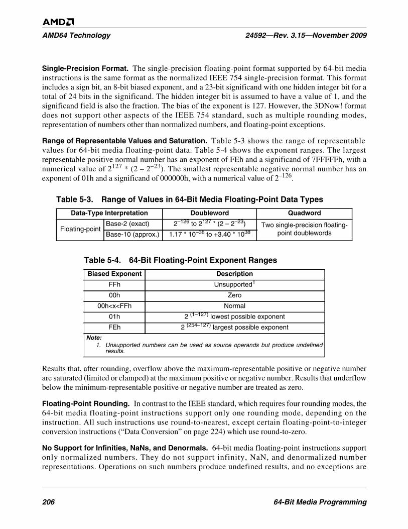
206 64-Bit Media Programming
AMD64 Technology 24592—Rev. 3.15—November 2009
Single-Precision Format. The single-precision floating-point format supported by 64-bit mediainstructions is the same format as the normalized IEEE 754 single-precision format. This formatincludes a sign bit, an 8-bit biased exponent, and a 23-bit significand with one hidden integer bit for atotal of 24 bits in the significand. The hidden integer bit is assumed to have a value of 1, and thesignificand field is also the fraction. The bias of the exponent is 127. However, the 3DNow! formatdoes not support other aspects of the IEEE 754 standard, such as multiple rounding modes,representation of numbers other than normalized numbers, and floating-point exceptions.
Range of Representable Values and Saturation. Table 5-3 shows the range of representablevalues for 64-bit media floating-point data. Table 5-4 shows the exponent ranges. The largestrepresentable positive normal number has an exponent of FEh and a significand of 7FFFFFh, with anumerical value of 2127 * (2 – 2–23). The smallest representable negative normal number has anexponent of 01h and a significand of 000000h, with a numerical value of 2–126.
Results that, after rounding, overflow above the maximum-representable positive or negative numberare saturated (limited or clamped) at the maximum positive or negative number. Results that underflowbelow the minimum-representable positive or negative number are treated as zero.
Floating-Point Rounding. In contrast to the IEEE standard, which requires four rounding modes, the64-bit media floating-point instructions support only one rounding mode, depending on theinstruction. All such instructions use round-to-nearest, except certain floating-point-to-integerconversion instructions (“Data Conversion” on page 224) which use round-to-zero.
No Support for Infinities, NaNs, and Denormals. 64-bit media floating-point instructions supportonly normalized numbers. They do not support infinity, NaN, and denormalized numberrepresentations. Operations on such numbers produce undefined results, and no exceptions are
Table 5-3. Range of Values in 64-Bit Media Floating-Point Data Types
Data-Type Interpretation Doubleword Quadword
Floating-pointBase-2 (exact) 2–126 to 2127 * (2 – 2–23) Two single-precision floating-
point doublewordsBase-10 (approx.) 1.17 * 10–38 to +3.40 * 1038
Table 5-4. 64-Bit Floating-Point Exponent Ranges
Biased Exponent Description
FFh Unsupported1
00h Zero
00h<x<FFh Normal
01h 2 (1–127) lowest possible exponent
FEh 2 (254–127) largest possible exponent
Note:1. Unsupported numbers can be used as source operands but produce undefined
results.
64-Bit Media Programming 207
24592—Rev. 3.15—November 2009 AMD64 Technology
generated. If all source operands are normalized numbers, these instructions never produce infinities,NaNs, or denormalized numbers as results.
This aspect of 64-bit media floating-point operations does not comply with the IEEE 754 standard.Software must use only normalized operands and ensure that computations remain within validnormalized-number ranges.
No Support for Floating-Point Exceptions. The 64-bit media floating-point instructions do notgenerate floating-point exceptions. Software must ensure that in-range operands are provided to theseinstructions.
5.6 Instruction Summary—Integer Instructions
This section summarizes the functions of the integer (MMX and a few SSE and SSE2) instructions inthe 64-bit media instruction subset. These include integer instructions that use an MMX register forsource or destination and data-conversion instructions that convert from integers to floating-pointformats. For a summary of the floating-point instructions in the 64-bit media instruction subset,including data-conversion instructions that convert from floating-point to integer formats, see“Instruction Summary—Floating-Point Instructions” on page 223.
The instructions are organized here by functional group—such as data-transfer, vector arithmetic, andso on. Software running at any privilege level can use any of these instructions, if the CPUIDinstruction reports support for the instructions (see “Feature Detection” on page 229). More detail onindividual instructions is given in the alphabetically organized “64-Bit Media Instruction Reference”in Volume 5.
5.6.1 Syntax
Each instruction has a mnemonic syntax used by assemblers to specify the operation and the operandsto be used for source and destination (result) data. The majority of 64-bit media integer instructionshave the following syntax:
MNEMONIC mmx1, mmx2/mem64
Figure 5-10 on page 208 shows an example of the mnemonic syntax for a packed add bytes (PADDB)instruction.
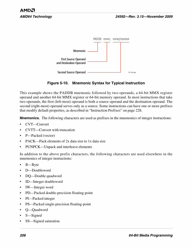
208 64-Bit Media Programming
AMD64 Technology 24592—Rev. 3.15—November 2009
Figure 5-10. Mnemonic Syntax for Typical Instruction
This example shows the PADDB mnemonic followed by two operands, a 64-bit MMX registeroperand and another 64-bit MMX register or 64-bit memory operand. In most instructions that taketwo operands, the first (left-most) operand is both a source operand and the destination operand. Thesecond (right-most) operand serves only as a source. Some instructions can have one or more prefixesthat modify default properties, as described in “Instruction Prefixes” on page 228.
Mnemonics. The following characters are used as prefixes in the mnemonics of integer instructions:
• CVT—Convert
• CVTT—Convert with truncation
• P—Packed (vector)
• PACK—Pack elements of 2x data size to 1x data size
• PUNPCK—Unpack and interleave elements
In addition to the above prefix characters, the following characters are used elsewhere in themnemonics of integer instructions:
• B—Byte
• D—Doubleword
• DQ—Double quadword
• ID—Integer doubleword
• IW—Integer word
• PD—Packed double-precision floating-point
• PI—Packed integer
• PS—Packed single-precision floating-point
• Q—Quadword
• S—Signed
• SS—Signed saturation
513-142.eps
Mnemonic
First Source Operandand Destination Operand
Second Source Operand
PADDB mmx1, mmx2/mem64
64-Bit Media Programming 209
24592—Rev. 3.15—November 2009 AMD64 Technology
• U—Unsigned
• US—Unsigned saturation
• W—Word
• x—One or more variable characters in the mnemonic
For example, the mnemonic for the instruction that packs four words into eight unsigned bytes isPACKUSWB. In this mnemonic, the PACK designates 2x-to-1x conversion of vector elements, the USdesignates unsigned results with saturation, and the WB designates vector elements of the source aswords and those of the result as bytes.
5.6.2 Exit Media State
The exit media state instructions are used to isolate the use of processor resources between 64-bitmedia instructions and x87 floating-point instructions.
• EMMS—Exit Media State
• FEMMS—Fast Exit Media State
These instructions initialize the contents of the x87 floating-point stack registers—called clearing theMMX state. Software should execute one of these instructions before leaving a 64-bit media procedure.
The EMMS and FEMMS instructions both clear the MMX state, as described in “Mixing Media Codewith x87 Code” on page 233. The instructions differ in one respect: FEMMS leaves the data in the x87stack registers undefined. By contrast, EMMS leaves the data in each such register as it was defined bythe last x87 or 64-bit media instruction that wrote to the register. The FEMMS instruction is supportedfor backward-compatibility. Software that must be compatible with both AMD and non-AMDprocessors should use the EMMS instruction.
5.6.3 Data Transfer
The data-transfer instructions copy operands between a 32-bit or 64-bit memory location, an MMXregister, an XMM register, or a GPR. The MOV mnemonic, which stands for move, is a misnomer. Acopy function is actually performed instead of a move.
Move
• MOVD—Move Doubleword
• MOVQ—Move Quadword
• MOVDQ2Q—Move Double Quadword to Quadword
• MOVQ2DQ—Move Quadword to Double Quadword
The MOVD instruction copies a 32-bit or 64-bit value from a general-purpose register (GPR) ormemory location to an MMX register, or from an MMX register to a GPR or memory location. If thesource operand is 32 bits and the destination operand is 64 bits, the source is zero-extended to 64 bitsin the destination. If the source is 64 bits and the destination is 32 bits, only the low-order 32 bits of thesource are copied to the destination.
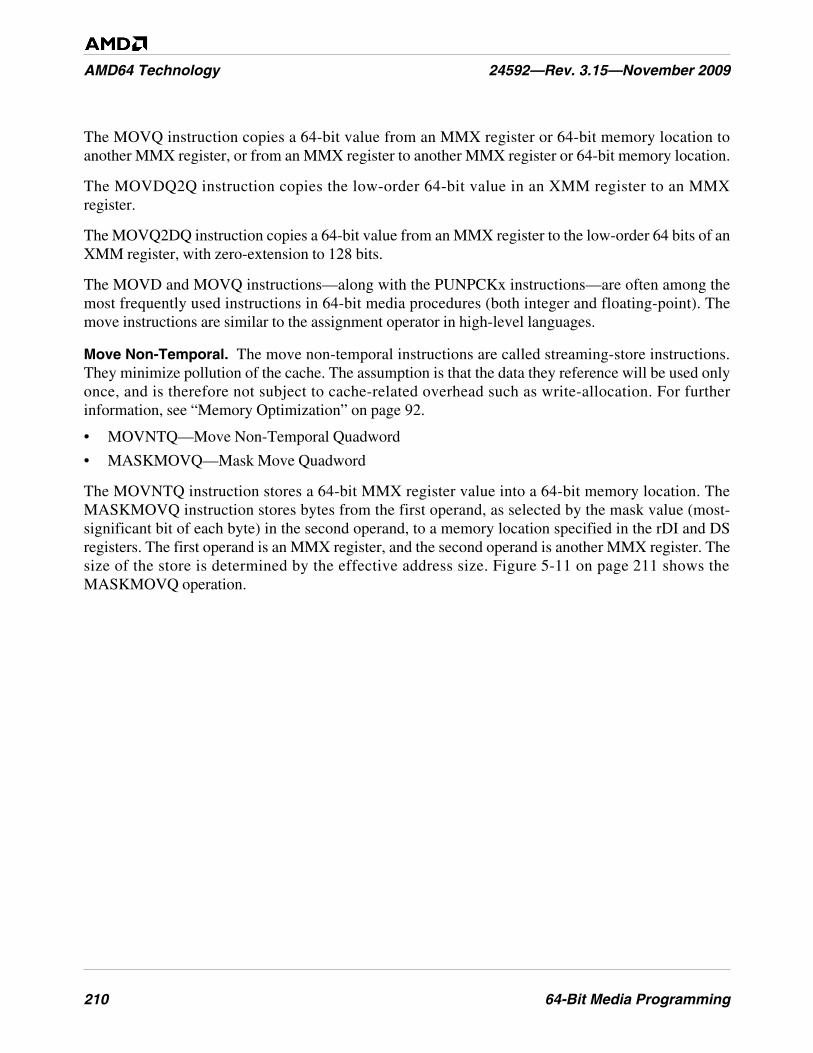
210 64-Bit Media Programming
AMD64 Technology 24592—Rev. 3.15—November 2009
The MOVQ instruction copies a 64-bit value from an MMX register or 64-bit memory location toanother MMX register, or from an MMX register to another MMX register or 64-bit memory location.
The MOVDQ2Q instruction copies the low-order 64-bit value in an XMM register to an MMXregister.
The MOVQ2DQ instruction copies a 64-bit value from an MMX register to the low-order 64 bits of anXMM register, with zero-extension to 128 bits.
The MOVD and MOVQ instructions—along with the PUNPCKx instructions—are often among themost frequently used instructions in 64-bit media procedures (both integer and floating-point). Themove instructions are similar to the assignment operator in high-level languages.
Move Non-Temporal. The move non-temporal instructions are called streaming-store instructions.They minimize pollution of the cache. The assumption is that the data they reference will be used onlyonce, and is therefore not subject to cache-related overhead such as write-allocation. For furtherinformation, see “Memory Optimization” on page 92.
• MOVNTQ—Move Non-Temporal Quadword
• MASKMOVQ—Mask Move Quadword
The MOVNTQ instruction stores a 64-bit MMX register value into a 64-bit memory location. TheMASKMOVQ instruction stores bytes from the first operand, as selected by the mask value (most-significant bit of each byte) in the second operand, to a memory location specified in the rDI and DSregisters. The first operand is an MMX register, and the second operand is another MMX register. Thesize of the store is determined by the effective address size. Figure 5-11 on page 211 shows theMASKMOVQ operation.
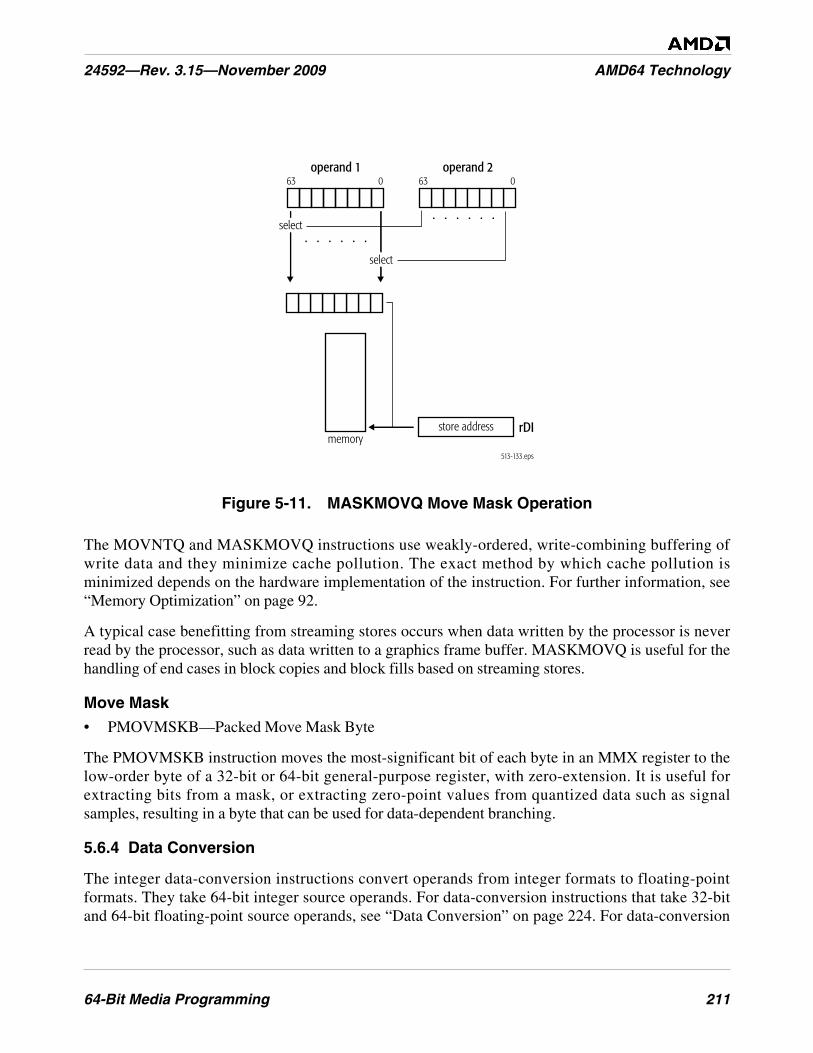
64-Bit Media Programming 211
24592—Rev. 3.15—November 2009 AMD64 Technology
Figure 5-11. MASKMOVQ Move Mask Operation
The MOVNTQ and MASKMOVQ instructions use weakly-ordered, write-combining buffering ofwrite data and they minimize cache pollution. The exact method by which cache pollution isminimized depends on the hardware implementation of the instruction. For further information, see“Memory Optimization” on page 92.
A typical case benefitting from streaming stores occurs when data written by the processor is neverread by the processor, such as data written to a graphics frame buffer. MASKMOVQ is useful for thehandling of end cases in block copies and block fills based on streaming stores.
Move Mask
• PMOVMSKB—Packed Move Mask Byte
The PMOVMSKB instruction moves the most-significant bit of each byte in an MMX register to thelow-order byte of a 32-bit or 64-bit general-purpose register, with zero-extension. It is useful forextracting bits from a mask, or extracting zero-point values from quantized data such as signalsamples, resulting in a byte that can be used for data-dependent branching.
5.6.4 Data Conversion
The integer data-conversion instructions convert operands from integer formats to floating-pointformats. They take 64-bit integer source operands. For data-conversion instructions that take 32-bitand 64-bit floating-point source operands, see “Data Conversion” on page 224. For data-conversion
operand 1
. . . . . .
. . . . . .
63 0operand 2
63 0
select
select
store addressmemory
rDI
513-133.eps
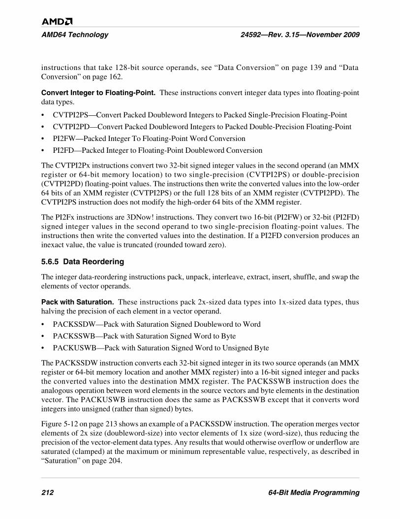
212 64-Bit Media Programming
AMD64 Technology 24592—Rev. 3.15—November 2009
instructions that take 128-bit source operands, see “Data Conversion” on page 139 and “DataConversion” on page 162.
Convert Integer to Floating-Point. These instructions convert integer data types into floating-pointdata types.
• CVTPI2PS—Convert Packed Doubleword Integers to Packed Single-Precision Floating-Point
• CVTPI2PD—Convert Packed Doubleword Integers to Packed Double-Precision Floating-Point
• PI2FW—Packed Integer To Floating-Point Word Conversion
• PI2FD—Packed Integer to Floating-Point Doubleword Conversion
The CVTPI2Px instructions convert two 32-bit signed integer values in the second operand (an MMXregister or 64-bit memory location) to two single-precision (CVTPI2PS) or double-precision(CVTPI2PD) floating-point values. The instructions then write the converted values into the low-order64 bits of an XMM register (CVTPI2PS) or the full 128 bits of an XMM register (CVTPI2PD). TheCVTPI2PS instruction does not modify the high-order 64 bits of the XMM register.
The PI2Fx instructions are 3DNow! instructions. They convert two 16-bit (PI2FW) or 32-bit (PI2FD)signed integer values in the second operand to two single-precision floating-point values. Theinstructions then write the converted values into the destination. If a PI2FD conversion produces aninexact value, the value is truncated (rounded toward zero).
5.6.5 Data Reordering
The integer data-reordering instructions pack, unpack, interleave, extract, insert, shuffle, and swap theelements of vector operands.
Pack with Saturation. These instructions pack 2x-sized data types into 1x-sized data types, thushalving the precision of each element in a vector operand.
• PACKSSDW—Pack with Saturation Signed Doubleword to Word
• PACKSSWB—Pack with Saturation Signed Word to Byte
• PACKUSWB—Pack with Saturation Signed Word to Unsigned Byte
The PACKSSDW instruction converts each 32-bit signed integer in its two source operands (an MMXregister or 64-bit memory location and another MMX register) into a 16-bit signed integer and packsthe converted values into the destination MMX register. The PACKSSWB instruction does theanalogous operation between word elements in the source vectors and byte elements in the destinationvector. The PACKUSWB instruction does the same as PACKSSWB except that it converts wordintegers into unsigned (rather than signed) bytes.
Figure 5-12 on page 213 shows an example of a PACKSSDW instruction. The operation merges vectorelements of 2x size (doubleword-size) into vector elements of 1x size (word-size), thus reducing theprecision of the vector-element data types. Any results that would otherwise overflow or underflow aresaturated (clamped) at the maximum or minimum representable value, respectively, as described in“Saturation” on page 204.
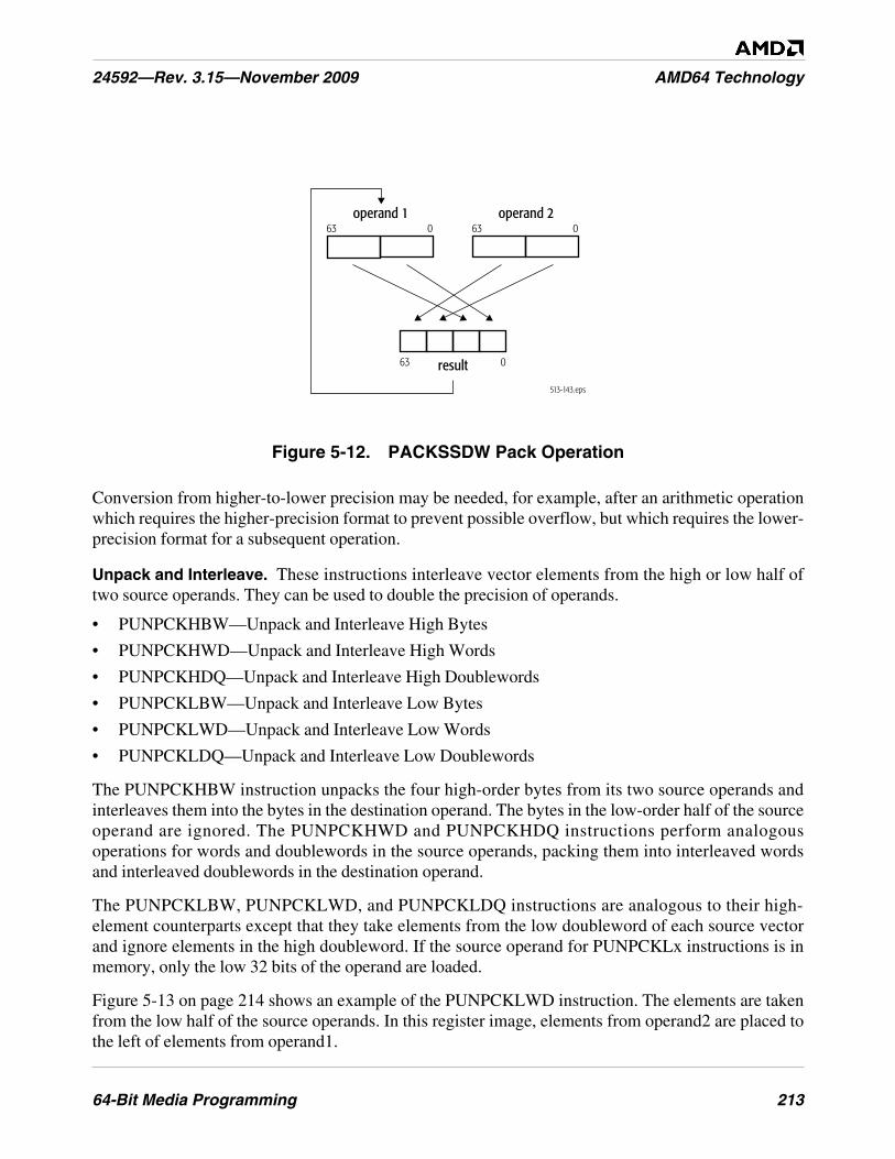
64-Bit Media Programming 213
24592—Rev. 3.15—November 2009 AMD64 Technology
Figure 5-12. PACKSSDW Pack Operation
Conversion from higher-to-lower precision may be needed, for example, after an arithmetic operationwhich requires the higher-precision format to prevent possible overflow, but which requires the lower-precision format for a subsequent operation.
Unpack and Interleave. These instructions interleave vector elements from the high or low half oftwo source operands. They can be used to double the precision of operands.
• PUNPCKHBW—Unpack and Interleave High Bytes
• PUNPCKHWD—Unpack and Interleave High Words
• PUNPCKHDQ—Unpack and Interleave High Doublewords
• PUNPCKLBW—Unpack and Interleave Low Bytes
• PUNPCKLWD—Unpack and Interleave Low Words
• PUNPCKLDQ—Unpack and Interleave Low Doublewords
The PUNPCKHBW instruction unpacks the four high-order bytes from its two source operands andinterleaves them into the bytes in the destination operand. The bytes in the low-order half of the sourceoperand are ignored. The PUNPCKHWD and PUNPCKHDQ instructions perform analogousoperations for words and doublewords in the source operands, packing them into interleaved wordsand interleaved doublewords in the destination operand.
The PUNPCKLBW, PUNPCKLWD, and PUNPCKLDQ instructions are analogous to their high-element counterparts except that they take elements from the low doubleword of each source vectorand ignore elements in the high doubleword. If the source operand for PUNPCKLx instructions is inmemory, only the low 32 bits of the operand are loaded.
Figure 5-13 on page 214 shows an example of the PUNPCKLWD instruction. The elements are takenfrom the low half of the source operands. In this register image, elements from operand2 are placed tothe left of elements from operand1.
513-143.eps
operand 1
result
63 0
63 0
operand 263 0
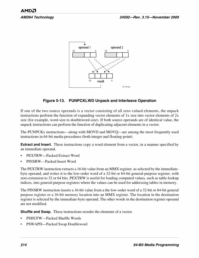
214 64-Bit Media Programming
AMD64 Technology 24592—Rev. 3.15—November 2009
Figure 5-13. PUNPCKLWD Unpack and Interleave Operation
If one of the two source operands is a vector consisting of all zero-valued elements, the unpackinstructions perform the function of expanding vector elements of 1x size into vector elements of 2xsize (for example, word-size to doubleword-size). If both source operands are of identical value, theunpack instructions can perform the function of duplicating adjacent elements in a vector.
The PUNPCKx instructions—along with MOVD and MOVQ—are among the most frequently usedinstructions in 64-bit media procedures (both integer and floating-point).
Extract and Insert. These instructions copy a word element from a vector, in a manner specified byan immediate operand.
• PEXTRW—Packed Extract Word
• PINSRW—Packed Insert Word
The PEXTRW instruction extracts a 16-bit value from an MMX register, as selected by the immediate-byte operand, and writes it to the low-order word of a 32-bit or 64-bit general-purpose register, withzero-extension to 32 or 64 bits. PEXTRW is useful for loading computed values, such as table-lookupindices, into general-purpose registers where the values can be used for addressing tables in memory.
The PINSRW instruction inserts a 16-bit value from a the low-order word of a 32-bit or 64-bit generalpurpose register or a 16-bit memory location into an MMX register. The location in the destinationregister is selected by the immediate-byte operand. The other words in the destination register operandare not modified.
Shuffle and Swap. These instructions reorder the elements of a vector.
• PSHUFW—Packed Shuffle Words
• PSWAPD—Packed Swap Doubleword
513-144.eps
operand 1
result
63 0
63 0
operand 263 0
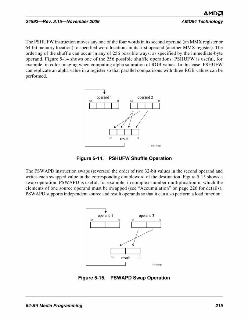
64-Bit Media Programming 215
24592—Rev. 3.15—November 2009 AMD64 Technology
The PSHUFW instruction moves any one of the four words in its second operand (an MMX register or64-bit memory location) to specified word locations in its first operand (another MMX register). Theordering of the shuffle can occur in any of 256 possible ways, as specified by the immediate-byteoperand. Figure 5-14 shows one of the 256 possible shuffle operations. PSHUFW is useful, forexample, in color imaging when computing alpha saturation of RGB values. In this case, PSHUFWcan replicate an alpha value in a register so that parallel comparisons with three RGB values can beperformed.
Figure 5-14. PSHUFW Shuffle Operation
The PSWAPD instruction swaps (reverses) the order of two 32-bit values in the second operand andwrites each swapped value in the corresponding doubleword of the destination. Figure 5-15 shows aswap operation. PSWAPD is useful, for example, in complex-number multiplication in which theelements of one source operand must be swapped (see “Accumulation” on page 226 for details).PSWAPD supports independent source and result operands so that it can also perform a load function.
Figure 5-15. PSWAPD Swap Operation
513-126.eps
operand 2operand 1
result
63 0
63 0
63 0
513-132.eps
operand 1
result
63 0operand 2
63 0
63 0
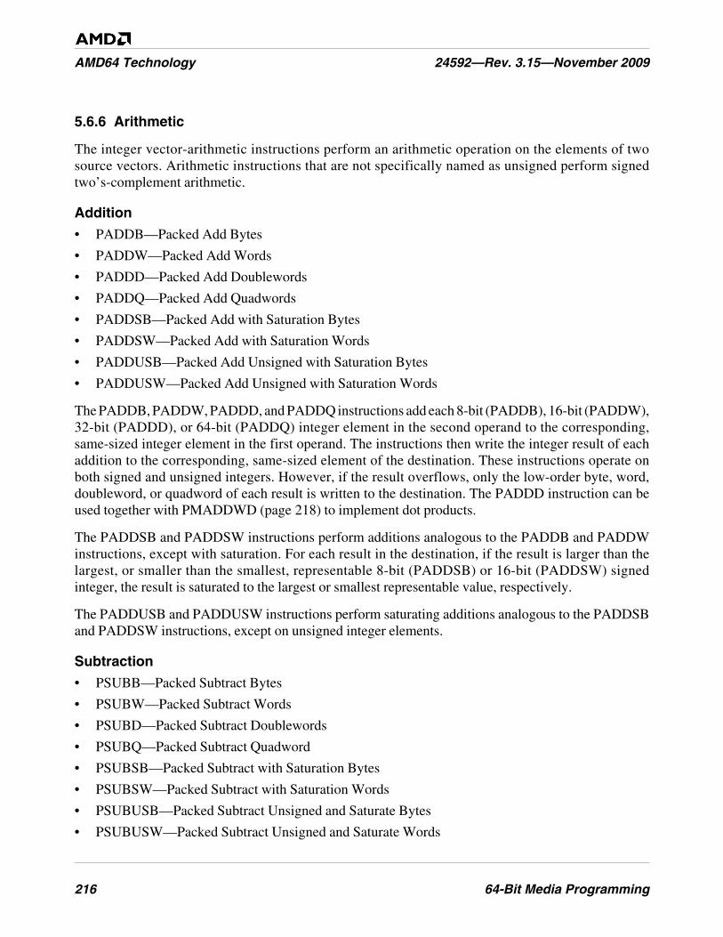
216 64-Bit Media Programming
AMD64 Technology 24592—Rev. 3.15—November 2009
5.6.6 Arithmetic
The integer vector-arithmetic instructions perform an arithmetic operation on the elements of twosource vectors. Arithmetic instructions that are not specifically named as unsigned perform signedtwo’s-complement arithmetic.
Addition
• PADDB—Packed Add Bytes
• PADDW—Packed Add Words
• PADDD—Packed Add Doublewords
• PADDQ—Packed Add Quadwords
• PADDSB—Packed Add with Saturation Bytes
• PADDSW—Packed Add with Saturation Words
• PADDUSB—Packed Add Unsigned with Saturation Bytes
• PADDUSW—Packed Add Unsigned with Saturation Words
The PADDB, PADDW, PADDD, and PADDQ instructions add each 8-bit (PADDB), 16-bit (PADDW),32-bit (PADDD), or 64-bit (PADDQ) integer element in the second operand to the corresponding,same-sized integer element in the first operand. The instructions then write the integer result of eachaddition to the corresponding, same-sized element of the destination. These instructions operate onboth signed and unsigned integers. However, if the result overflows, only the low-order byte, word,doubleword, or quadword of each result is written to the destination. The PADDD instruction can beused together with PMADDWD (page 218) to implement dot products.
The PADDSB and PADDSW instructions perform additions analogous to the PADDB and PADDWinstructions, except with saturation. For each result in the destination, if the result is larger than thelargest, or smaller than the smallest, representable 8-bit (PADDSB) or 16-bit (PADDSW) signedinteger, the result is saturated to the largest or smallest representable value, respectively.
The PADDUSB and PADDUSW instructions perform saturating additions analogous to the PADDSBand PADDSW instructions, except on unsigned integer elements.
Subtraction
• PSUBB—Packed Subtract Bytes
• PSUBW—Packed Subtract Words
• PSUBD—Packed Subtract Doublewords
• PSUBQ—Packed Subtract Quadword
• PSUBSB—Packed Subtract with Saturation Bytes
• PSUBSW—Packed Subtract with Saturation Words
• PSUBUSB—Packed Subtract Unsigned and Saturate Bytes
• PSUBUSW—Packed Subtract Unsigned and Saturate Words
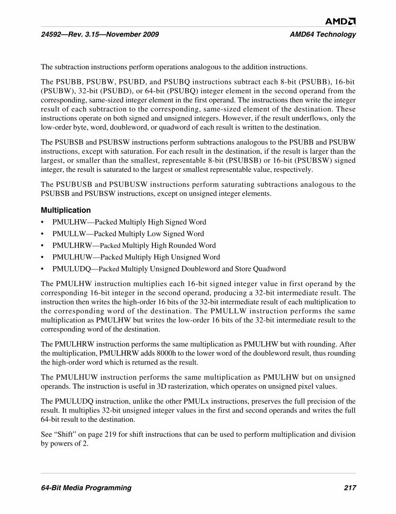
64-Bit Media Programming 217
24592—Rev. 3.15—November 2009 AMD64 Technology
The subtraction instructions perform operations analogous to the addition instructions.
The PSUBB, PSUBW, PSUBD, and PSUBQ instructions subtract each 8-bit (PSUBB), 16-bit(PSUBW), 32-bit (PSUBD), or 64-bit (PSUBQ) integer element in the second operand from thecorresponding, same-sized integer element in the first operand. The instructions then write the integerresult of each subtraction to the corresponding, same-sized element of the destination. Theseinstructions operate on both signed and unsigned integers. However, if the result underflows, only thelow-order byte, word, doubleword, or quadword of each result is written to the destination.
The PSUBSB and PSUBSW instructions perform subtractions analogous to the PSUBB and PSUBWinstructions, except with saturation. For each result in the destination, if the result is larger than thelargest, or smaller than the smallest, representable 8-bit (PSUBSB) or 16-bit (PSUBSW) signedinteger, the result is saturated to the largest or smallest representable value, respectively.
The PSUBUSB and PSUBUSW instructions perform saturating subtractions analogous to thePSUBSB and PSUBSW instructions, except on unsigned integer elements.
Multiplication
• PMULHW—Packed Multiply High Signed Word
• PMULLW—Packed Multiply Low Signed Word
• PMULHRW—Packed Multiply High Rounded Word
• PMULHUW—Packed Multiply High Unsigned Word
• PMULUDQ—Packed Multiply Unsigned Doubleword and Store Quadword
The PMULHW instruction multiplies each 16-bit signed integer value in first operand by thecorresponding 16-bit integer in the second operand, producing a 32-bit intermediate result. Theinstruction then writes the high-order 16 bits of the 32-bit intermediate result of each multiplication tothe corresponding word of the destination. The PMULLW instruction performs the samemultiplication as PMULHW but writes the low-order 16 bits of the 32-bit intermediate result to thecorresponding word of the destination.
The PMULHRW instruction performs the same multiplication as PMULHW but with rounding. Afterthe multiplication, PMULHRW adds 8000h to the lower word of the doubleword result, thus roundingthe high-order word which is returned as the result.
The PMULHUW instruction performs the same multiplication as PMULHW but on unsignedoperands. The instruction is useful in 3D rasterization, which operates on unsigned pixel values.
The PMULUDQ instruction, unlike the other PMULx instructions, preserves the full precision of theresult. It multiplies 32-bit unsigned integer values in the first and second operands and writes the full64-bit result to the destination.
See “Shift” on page 219 for shift instructions that can be used to perform multiplication and divisionby powers of 2.
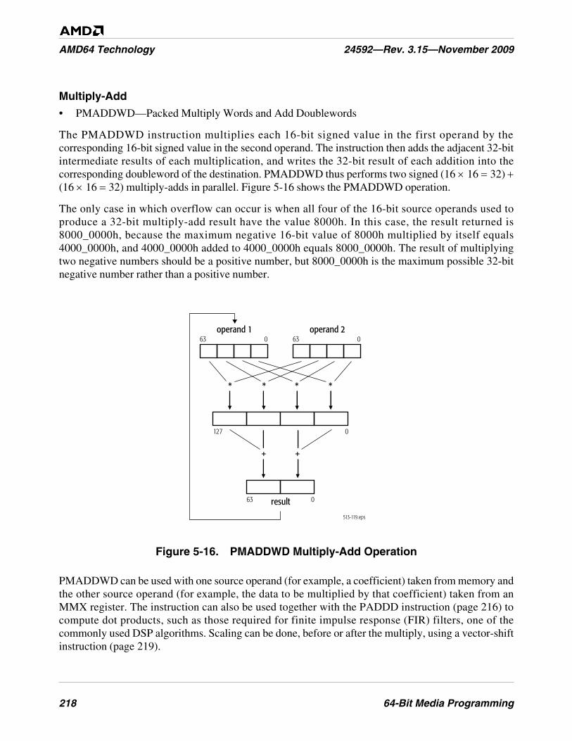
218 64-Bit Media Programming
AMD64 Technology 24592—Rev. 3.15—November 2009
Multiply-Add
• PMADDWD—Packed Multiply Words and Add Doublewords
The PMADDWD instruction multiplies each 16-bit signed value in the first operand by thecorresponding 16-bit signed value in the second operand. The instruction then adds the adjacent 32-bitintermediate results of each multiplication, and writes the 32-bit result of each addition into thecorresponding doubleword of the destination. PMADDWD thus performs two signed (16 × 16 = 32) +(16 × 16 = 32) multiply-adds in parallel. Figure 5-16 shows the PMADDWD operation.
The only case in which overflow can occur is when all four of the 16-bit source operands used toproduce a 32-bit multiply-add result have the value 8000h. In this case, the result returned is8000_0000h, because the maximum negative 16-bit value of 8000h multiplied by itself equals4000_0000h, and 4000_0000h added to 4000_0000h equals 8000_0000h. The result of multiplyingtwo negative numbers should be a positive number, but 8000_0000h is the maximum possible 32-bitnegative number rather than a positive number.
Figure 5-16. PMADDWD Multiply-Add Operation
PMADDWD can be used with one source operand (for example, a coefficient) taken from memory andthe other source operand (for example, the data to be multiplied by that coefficient) taken from anMMX register. The instruction can also be used together with the PADDD instruction (page 216) tocompute dot products, such as those required for finite impulse response (FIR) filters, one of thecommonly used DSP algorithms. Scaling can be done, before or after the multiply, using a vector-shiftinstruction (page 219).
513-119.eps
operand 1
result
63 0
63 0
operand 263 0
127 0
*
+ +
***

64-Bit Media Programming 219
24592—Rev. 3.15—November 2009 AMD64 Technology
For floating-point multiplication operations, see the PFMUL instruction on page 225. For floating-point accumulation operations, see the PFACC, PFNACC, and PFPNACC instructions on page 226.
Average
• PAVGB—Packed Average Unsigned Bytes
• PAVGW—Packed Average Unsigned Words
• PAVGUSB—Packed Average Unsigned Packed Bytes
The PAVGx instructions compute the rounded average of each unsigned 8-bit (PAVGB) or 16-bit(PAVGW) integer value in the first operand and the corresponding, same-sized unsigned integer in thesecond operand. The instructions then write each average in the corresponding, same-sized element ofthe destination. The rounded average is computed by adding each pair of operands, adding 1 to thetemporary sum, and then right-shifting the temporary sum by one bit.
The PAVGB instruction is useful for MPEG decoding, in which motion compensation performs manybyte-averaging operations between and within macroblocks. In addition to speeding up theseoperations, PAVGB can free up registers and make it possible to unroll the averaging loops.
The PAVGUSB instruction (a 3DNow! instruction) performs a function identical to the PAVGBinstruction, described on page 219, although the two instructions have different opcodes.
Sum of Absolute Differences
• PSADBW—Packed Sum of Absolute Differences of Bytes into a Word
The PSADBW instruction computes the absolute values of the differences of corresponding 8-bitsigned integer values in the first and second operands. The instruction then sums the differences andwrites an unsigned 16-bit integer result in the low-order word of the destination. The remaining bytesin the destination are cleared to all 0s.
Sums of absolute differences are used to compute the L1 norm in motion-estimation algorithms forvideo compression.
5.6.7 Shift
The vector-shift instructions are useful for scaling vector elements to higher or lower precision,packing and unpacking vector elements, and multiplying and dividing vector elements by powers of 2.
Left Logical Shift
• PSLLW—Packed Shift Left Logical Words
• PSLLD—Packed Shift Left Logical Doublewords
• PSLLQ—Packed Shift Left Logical Quadwords
The PSLLx instructions left-shift each of the 16-bit (PSLLW), 32-bit (PSLLD), or 64-bit (PSLLQ)values in the first operand by the number of bits specified in the second operand. The instructions thenwrite each shifted value into the corresponding, same-sized element of the destination. The first and
220 64-Bit Media Programming
AMD64 Technology 24592—Rev. 3.15—November 2009
second operands are either an MMX register and another MMX register or 64-bit memory location, oran MMX register and an immediate-byte value. The low-order bits that are emptied by the shiftoperation are cleared to 0.
In integer arithmetic, left logical shifts effectively multiply unsigned operands by positive powers of 2.
Right Logical Shift
• PSRLW—Packed Shift Right Logical Words
• PSRLD—Packed Shift Right Logical Doublewords
• PSRLQ—Packed Shift Right Logical Quadwords
The PSRLx instructions right-shift each of the 16-bit (PSRLW), 32-bit (PSRLD), or 64-bit (PSRLQ)values in the first operand by the number of bits specified in the second operand. The instructions thenwrite each shifted value into the corresponding, same-sized element of the destination. The first andsecond operands are either an MMX register and another MMX register or 64-bit memory location, oran MMX register and an immediate-byte value. The high-order bits that are emptied by the shiftoperation are cleared to 0. In integer arithmetic, right logical shifts effectively divide unsignedoperands or positive signed operands by positive powers of 2.
PSRLQ can be used to move the high 32 bits of an MMX register to the low 32 bits of the register.
Right Arithmetic Shift
• PSRAW—Packed Shift Right Arithmetic Words
• PSRAD—Packed Shift Right Arithmetic Doublewords
The PSRAx instructions right-shifts each of the 16-bit (PSRAW) or 32-bit (PSRAD) values in the firstoperand by the number of bits specified in the second operand. The instructions then write each shiftedvalue into the corresponding, same-sized element of the destination. The high-order bits that areemptied by the shift operation are filled with the sign bit of the initial value.
In integer arithmetic, right arithmetic shifts effectively divide signed operands by positive powers of 2.
5.6.8 Compare
The integer vector-compare instructions compare two operands, and they either write a mask or theywrite the maximum or minimum value.
Compare and Write Mask
• PCMPEQB—Packed Compare Equal Bytes
• PCMPEQW—Packed Compare Equal Words
• PCMPEQD—Packed Compare Equal Doublewords
• PCMPGTB—Packed Compare Greater Than Signed Bytes
• PCMPGTW—Packed Compare Greater Than Signed Words
• PCMPGTD—Packed Compare Greater Than Signed Doublewords

64-Bit Media Programming 221
24592—Rev. 3.15—November 2009 AMD64 Technology
The PCMPEQx and PCMPGTx instructions compare corresponding bytes, words, or doubleword inthe first and second operands. The instructions then write a mask of all 1s or 0s for each compare intothe corresponding, same-sized element of the destination.
For the PCMPEQx instructions, if the compared values are equal, the result mask is all 1s. If the valuesare not equal, the result mask is all 0s. For the PCMPGTx instructions, if the signed value in the firstoperand is greater than the signed value in the second operand, the result mask is all 1s. If the value inthe first operand is less than or equal to the value in the second operand, the result mask is all 0s.PCMPEQx can be used to set the bits in an MMX register to all 1s by specifying the same register forboth operands.
By specifying the same register for both operands, PCMPEQx can be used to set the bits in an MMXregister to all 1s.
Figure 5-5 on page 198 shows an example of a non-branching sequence that implements a two-waymultiplexer—one that is equivalent to the following sequence of ternary operators in C or C++:
r0 = a0 > b0 ? a0 : b0r1 = a1 > b1 ? a1 : b1r2 = a2 > b2 ? a2 : b2r3 = a3 > b3 ? a3 : b3
Assuming mmx0 contains a, and mmx1 contains b, the above C sequence can be implemented with thefollowing assembler sequence:
MOVQ mmx3, mmx0PCMPGTW mmx3, mmx2 ; a > b ? 0xffff : 0PAND mmx0, mmx3 ; a > b ? a: 0PANDN mmx3, mmx1 ; a > b > 0 : bPOR mmx0, mmx3 ; r = a > b ? a: b
In the above sequence, PCMPGTW, PAND, PANDN, and POR operate, in parallel, on all fourelements of the vectors.
Compare and Write Minimum or Maximum
• PMAXUB—Packed Maximum Unsigned Bytes
• PMINUB—Packed Minimum Unsigned Bytes
• PMAXSW—Packed Maximum Signed Words
• PMINSW—Packed Minimum Signed Words
The PMAXUB and PMINUB instructions compare each of the 8-bit unsigned integer values in thefirst operand with the corresponding 8-bit unsigned integer values in the second operand. Theinstructions then write the maximum (PMAXUB) or minimum (PMINUB) of the two values for eachcomparison into the corresponding byte of the destination.
The PMAXSW and PMINSW instructions perform operations analogous to the PMAXUB andPMINUB instructions, except on 16-bit signed integer values.
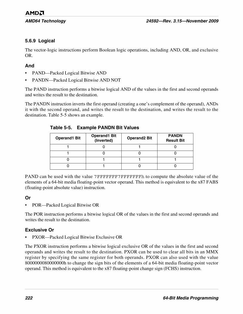
222 64-Bit Media Programming
AMD64 Technology 24592—Rev. 3.15—November 2009
5.6.9 Logical
The vector-logic instructions perform Boolean logic operations, including AND, OR, and exclusiveOR.
And
• PAND—Packed Logical Bitwise AND
• PANDN—Packed Logical Bitwise AND NOT
The PAND instruction performs a bitwise logical AND of the values in the first and second operandsand writes the result to the destination.
The PANDN instruction inverts the first operand (creating a one’s complement of the operand), ANDsit with the second operand, and writes the result to the destination, and writes the result to thedestination. Table 5-5 shows an example.
PAND can be used with the value 7FFFFFFF7FFFFFFFh to compute the absolute value of theelements of a 64-bit media floating-point vector operand. This method is equivalent to the x87 FABS(floating-point absolute value) instruction.
Or
• POR—Packed Logical Bitwise OR
The POR instruction performs a bitwise logical OR of the values in the first and second operands andwrites the result to the destination.
Exclusive Or
• PXOR—Packed Logical Bitwise Exclusive OR
The PXOR instruction performs a bitwise logical exclusive OR of the values in the first and secondoperands and writes the result to the destination. PXOR can be used to clear all bits in an MMXregister by specifying the same register for both operands. PXOR can also used with the value8000000080000000h to change the sign bits of the elements of a 64-bit media floating-point vectoroperand. This method is equivalent to the x87 floating-point change sign (FCHS) instruction.
Table 5-5. Example PANDN Bit Values
Operand1 BitOperand1 Bit
(Inverted)Operand2 Bit
PANDNResult Bit
1 0 1 0
1 0 0 0
0 1 1 1
0 1 0 0
64-Bit Media Programming 223
24592—Rev. 3.15—November 2009 AMD64 Technology
5.6.10 Save and Restore State
These instructions save and restore the processor state for 64-bit media instructions.
Save and Restore 64-Bit Media and x87 State
• FSAVE—Save x87 and MMX State
• FNSAVE—Save No-Wait x87 and MMX State
• FRSTOR—Restore x87 and MMX State
These instructions save and restore the entire processor state for x87 floating-point instructions and64-bit media instructions. The instructions save and restore either 94 or 108 bytes of data, dependingon the effective operand size.
Assemblers issue FSAVE as an FWAIT instruction followed by an FNSAVE instruction. Thus, FSAVE(but not FNSAVE) reports pending unmasked x87 floating-point exceptions before saving the state.After saving the state, the processor initializes the x87 state by performing the equivalent of an FINITinstruction.
Save and Restore 128-Bit, 64-Bit, and x87 State
• FXSAVE—Save XMM, MMX, and x87 State
• FXRSTOR—Restore XMM, MMX, and x87 State
The FXSAVE and FXRSTOR instructions save and restore the entire 512-byte processor state for 128-bit media instructions, 64-bit media instructions, and x87 floating-point instructions. The architecturesupports two memory formats for FXSAVE and FXRSTOR, a 512-byte 32-bit legacy format and a512-byte 64-bit format. Selection of the 32-bit or 64-bit format is determined by the effective operandsize for the FXSAVE and FXRSTOR instructions. For details, see “FXSAVE and FXRSTORInstructions” in Volume 2.
FXSAVE and FXRSTOR execute faster than FSAVE/FNSAVE and FRSTOR. However, unlikeFSAVE and FNSAVE, FXSAVE does not initialize the x87 state, and like FNSAVE it does not reportpending unmasked x87 floating-point exceptions. For details, see “Saving and Restoring State” onpage 234.
5.7 Instruction Summary—Floating-Point Instructions
This section summarizes the functions of the floating-point (3DNow! and a few SSE and SSE2)instructions in the 64-bit media instruction subset. These include floating-point instructions that use anMMX register for source or destination and data-conversion instructions that convert from floating-point to integers formats. For a summary of the integer instructions in the 64-bit media instructionsubset, including data-conversion instructions that convert from integer to floating-point formats, see“Instruction Summary—Integer Instructions” on page 207.
224 64-Bit Media Programming
AMD64 Technology 24592—Rev. 3.15—November 2009
For a summary of the 128-bit media floating-point instructions, see “Instruction Summary—Floating-Point Instructions” on page 156. For a summary of the x87 floating-point instructions, see “InstructionSummary” on page 261.
The instructions are organized here by functional group—such as data-transfer, vector arithmetic, andso on. Software running at any privilege level can use any of these instructions, if the CPUIDinstruction reports support for the instructions (see “Feature Detection” on page 229). More detail onindividual instructions is given in the alphabetically organized “64-Bit Media Instruction Reference”in Volume 5.
5.7.1 Syntax
The 64-bit media floating-point instructions have the same syntax rules as those for the 64-bit mediainteger instructions, described in “Syntax” on page 207, except that the mnemonics of most floating-point instructions begin with the following prefix:
• PF—Packed floating-point
5.7.2 Data Conversion
These data-conversion instructions convert operands from floating-point to integer formats. Theinstructions take 32-bit or 64-bit floating-point source operands. For data-conversion instructions thattake 64-bit integer source operands, see “Data Conversion” on page 211. For data-conversioninstructions that take 128-bit source operands, see “Data Conversion” on page 139 and “DataConversion” on page 162.
Convert Floating-Point to Integer
• CVTPS2PI—Convert Packed Single-Precision Floating-Point to Packed Doubleword Integers
• CVTTPS2PI—Convert Packed Single-Precision Floating-Point to Packed Doubleword Integers,Truncated
• CVTPD2PI—Convert Packed Double-Precision Floating-Point to Packed Doubleword Integers
• CVTTPD2PI—Convert Packed Double-Precision Floating-Point to Packed Doubleword Integers,Truncated
• PF2IW—Packed Floating-Point to Integer Word Conversion
• PF2ID—Packed Floating-Point to Integer Doubleword Conversion
The CVTPS2PI and CVTTPS2PI instructions convert two single-precision (32-bit) floating-pointvalues in the second operand (the low-order 64 bits of an XMM register or a 64-bit memory location)to two 32-bit signed integers, and write the converted values into the first operand (an MMX register).For the CVTPS2PI instruction, if the conversion result is an inexact value, the value is rounded asspecified in the rounding control (RC) field of the MXCSR register (“MXCSR Register” on page 117),but for the CVTTPS2PI instruction such a result is truncated (rounded toward zero).
The CVTPD2PI and CVTTPD2PI instructions perform conversions analogous to CVTPS2PI andCVTTPS2PI but for two double-precision (64-bit) floating-point values.
64-Bit Media Programming 225
24592—Rev. 3.15—November 2009 AMD64 Technology
The 3DNow! PF2IW instruction converts two single-precision floating-point values in the secondoperand (an MMX register or a 64-bit memory location) to two 16-bit signed integer values, sign-extended to 32-bits, and writes the converted values into the first operand (an MMX register). The3DNow! PF2ID instruction converts two single-precision floating-point values in the second operandto two 32-bit signed integer values, and writes the converted values into the first operand. If the resultof either conversion is an inexact value, the value is truncated (rounded toward zero).
As described in “Floating-Point Data Types” on page 205, PF2IW and PF2ID do not fully comply withthe IEEE-754 standard. Conversion of some source operands of the C type float (IEEE-754 single-precision)—specifically NaNs, infinities, and denormals—are not supported. Attempts to convert suchsource operands produce undefined results, and no exceptions are generated.
5.7.3 Arithmetic
The floating-point vector-arithmetic instructions perform an arithmetic operation on two floating-point operands. For a description of 3DNow! instruction saturation on overflow and underflowconditions, see “Floating-Point Data Types” on page 205.
Addition
• PFADD—Packed Floating-Point Add
The PFADD instruction adds each single-precision floating-point value in the first operand (an MMXregister) to the corresponding single-precision floating-point value in the second operand (an MMXregister or 64-bit memory location). The instruction then writes the result of each addition into thecorresponding doubleword of the destination.
Subtraction
• PFSUB—Packed Floating-Point Subtract
• PFSUBR—Packed Floating-Point Subtract Reverse
The PFSUB instruction subtracts each single-precision floating-point value in the second operandfrom the corresponding single-precision floating-point value in the first operand. The instruction thenwrites the result of each subtraction into the corresponding quadword of the destination.
The PFSUBR instruction performs a subtraction that is the reverse of the PFSUB instruction. Itsubtracts each value in the first operand from the corresponding value in the second operand. Theprovision of both the PFSUB and PFSUBR instructions allows software to choose which sourceoperand to overwrite during a subtraction.
Multiplication
• PFMUL—Packed Floating-Point Multiply
The PFMUL instruction multiplies each of the two single-precision floating-point values in the firstoperand by the corresponding single-precision floating-point value in the second operand and writesthe result of each multiplication into the corresponding doubleword of the destination.
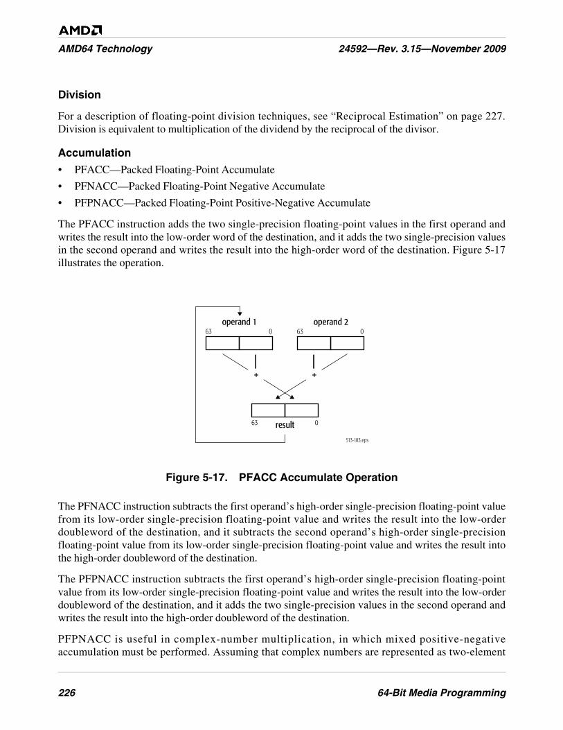
226 64-Bit Media Programming
AMD64 Technology 24592—Rev. 3.15—November 2009
Division
For a description of floating-point division techniques, see “Reciprocal Estimation” on page 227.Division is equivalent to multiplication of the dividend by the reciprocal of the divisor.
Accumulation
• PFACC—Packed Floating-Point Accumulate
• PFNACC—Packed Floating-Point Negative Accumulate
• PFPNACC—Packed Floating-Point Positive-Negative Accumulate
The PFACC instruction adds the two single-precision floating-point values in the first operand andwrites the result into the low-order word of the destination, and it adds the two single-precision valuesin the second operand and writes the result into the high-order word of the destination. Figure 5-17illustrates the operation.
Figure 5-17. PFACC Accumulate Operation
The PFNACC instruction subtracts the first operand’s high-order single-precision floating-point valuefrom its low-order single-precision floating-point value and writes the result into the low-orderdoubleword of the destination, and it subtracts the second operand’s high-order single-precisionfloating-point value from its low-order single-precision floating-point value and writes the result intothe high-order doubleword of the destination.
The PFPNACC instruction subtracts the first operand’s high-order single-precision floating-pointvalue from its low-order single-precision floating-point value and writes the result into the low-orderdoubleword of the destination, and it adds the two single-precision values in the second operand andwrites the result into the high-order doubleword of the destination.
PFPNACC is useful in complex-number multiplication, in which mixed positive-negativeaccumulation must be performed. Assuming that complex numbers are represented as two-element
513-183.eps
operand 1
result63 0
operand 263 063 0
+ +
64-Bit Media Programming 227
24592—Rev. 3.15—November 2009 AMD64 Technology
vectors (one element is the real part, the other element is the imaginary part), there is a need to swapthe elements of one source operand to perform the multiplication, and there is a need for mixedpositive-negative accumulation to complete the parallel computation of real and imaginary results. ThePSWAPD instruction can swap elements of one source operand and the PFPNACC instruction canperform the mixed positive-negative accumulation to complete the computation.
Reciprocal Estimation
• PFRCP—Packed Floating-Point Reciprocal Approximation
• PFRCPIT1—Packed Floating-Point Reciprocal, Iteration 1
• PFRCPIT2—Packed Floating-Point Reciprocal or Reciprocal Square Root, Iteration 2
The PFRCP instruction computes the approximate reciprocal of the single-precision floating-pointvalue in the low-order 32 bits of the second operand and writes the result into both doublewords of thefirst operand.
The PFRCPIT1 instruction performs the first intermediate step in the Newton-Raphson iteration torefine the reciprocal approximation produced by the PFRCP instruction. The first operand contains theinput to a previous PFRCP instruction, and the second operand contains the result of the same PFRCPinstruction.
The PFRCPIT2 instruction performs the second and final step in the Newton-Raphson iteration torefine the reciprocal approximation produced by the PFRCP instruction or the reciprocal square-rootapproximation produced by the PFSQRT instructions. The first operand contains the result of aprevious PFRCPIT1 or PFRSQIT1 instruction, and the second operand contains the result of a PFRCPor PFRSQRT instruction.
The PFRCP instruction can be used together with the PFRCPIT1 and PFRCPIT2 instructions toincrease the accuracy of a single-precision significand.
Reciprocal Square Root
• PFRSQRT—Packed Floating-Point Reciprocal Square Root Approximation
• PFRSQIT1—Packed Floating-Point Reciprocal Square Root, Iteration 1
The PFRSQRT instruction computes the approximate reciprocal square root of the single-precisionfloating-point value in the low-order 32 bits of the second operand and writes the result into eachdoubleword of the first operand. The second operand is a single-precision floating-point value with a24-bit significand. The result written to the first operand is accurate to 15 bits. Negative operands aretreated as positive operands for purposes of reciprocal square-root computation, with the sign of theresult the same as the sign of the source operand.
The PFRSQIT1 instruction performs the first step in the Newton-Raphson iteration to refine thereciprocal square-root approximation produced by the PFSQRT instruction. The first operand containsthe input to a previous PFRSQRT instruction, and the second operand contains the square of the resultof the same PFRSQRT instruction.

228 64-Bit Media Programming
AMD64 Technology 24592—Rev. 3.15—November 2009
The PFRSQRT instruction can be used together with the PFRSQIT1 instruction and the PFRCPIT2instruction (described in “Reciprocal Estimation” on page 227) to increase the accuracy of a single-precision significand.
5.7.4 Compare
The floating-point vector-compare instructions compare two operands, and they either write a mask orthey write the maximum or minimum value.
Compare and Write Mask
• PFCMPEQ—Packed Floating-Point Compare Equal
• PFCMPGT—Packed Floating-Point Compare Greater Than
• PFCMPGE—Packed Floating-Point Compare Greater or Equal
The PFCMPx instructions compare each of the two single-precision floating-point values in the firstoperand with the corresponding single-precision floating-point value in the second operand. Theinstructions then write the result of each comparison into the corresponding doubleword of thedestination. If the comparison test (equal, greater than, greater or equal) is true, the result is a mask ofall 1s. If the comparison test is false, the result is a mask of all 0s.
Compare and Write Minimum or Maximum
• PFMAX—Packed Floating-Point Maximum
• PFMIN—Packed Floating-Point Minimum
The PFMAX and PFMIN instructions compare each of the two single-precision floating-point valuesin the first operand with the corresponding single-precision floating-point value in the second operand.The instructions then write the maximum (PFMAX) or minimum (PFMIN) of the two values for eachcomparison into the corresponding doubleword of the destination.
The PFMIN and PFMAX instructions are useful for clamping, such as color clamping in 3D geometryand rasterization. They can also be used to avoid branching.
5.8 Instruction Effects on Flags
The 64-bit media instructions do not read or write any flags in the rFLAGS register, nor do they writeany exception-status flags in the x87 status-word register, nor is their execution dependent on anymask bits in the x87 control-word register. The only x87 state affected by the 64-bit media instructionsis described in “Actions Taken on Executing 64-Bit Media Instructions” on page 232.
5.9 Instruction Prefixes
Instruction prefixes, in general, are described in “Instruction Prefixes” on page 71. The followingrestrictions apply to the use of instruction prefixes with 64-bit media instructions.
64-Bit Media Programming 229
24592—Rev. 3.15—November 2009 AMD64 Technology
5.9.1 Supported Prefixes
The following prefixes can be used with 64-bit media instructions:
• Address-Size Override—The 67h prefix affects only operands in memory. The prefix is ignored byall other 64-bit media instructions.
• Operand-Size Override—The 66h prefix is used to form the opcodes of certain 64-bit mediainstructions. The prefix is ignored by all other 64-bit media instructions.
• Segment Overrides—The 2Eh (CS), 36h (SS), 3Eh (DS), 26h (ES), 64h (FS), and 65h (GS)prefixes affect only operands in memory. In 64-bit mode, the contents of the CS, DS, ES, SSsegment registers are ignored.
• REP—The F2 and F3h prefixes do not function as repeat prefixes for 64-bit media instructions.Instead, they are used to form the opcodes of certain 64-bit media instructions. The prefixes areignored by all other 64-bit media instructions.
• REX—The REX prefixes affect operands that reference a GPR or XMM register when running in64-bit mode. It allows access to the full 64-bit width of any of the 16 extended GPRs and to any ofthe 16 extended XMM registers. The REX prefix also affects the FXSAVE and FXRSTORinstructions, in which it selects between two types of 512-byte memory-image format, as describedin “Media and x87 Processor State” in Volume 2. The prefix is ignored by all other 64-bit mediainstructions.
5.9.2 Special-Use and Reserved Prefixes
The following prefixes are used as opcode bytes in some 64-bit media instructions and are reserved inall other 64-bit media instructions:
• Operand-Size Override—The 66h prefix.
• REP—The F2 and F3h prefixes.
5.9.3 Prefixes That Cause Exceptions
The following prefixes cause an exception:
• LOCK—The F0h prefix causes an invalid-opcode exception when used with 64-bit mediainstructions.
5.10 Feature Detection
Before executing 64-bit media instructions, software should determine whether the processor supportsthe technology by executing the CPUID instruction. “Feature Detection” on page 74 describes howsoftware uses the CPUID instruction to detect feature support. For full support of the 64-bit mediainstructions documented here, the following features require detection:
• MMX instructions, indicated by bit 23 of CPUID function 1 and function 8000_0001h.
• 3DNow! instructions, indicated by bit 31 of CPUID function 8000_0001h.
230 64-Bit Media Programming
AMD64 Technology 24592—Rev. 3.15—November 2009
• MMX extensions, indicated by bit 22 of CPUID function 8000_0001h.
• 3DNow! extensions, indicated by bit 30 of CPUID function 8000_0001h.
• SSE instructions, indicated by bit 25 of CPUID function 8000_0001h.
• SSE2 instruction extensions, indicated by bit 26 of CPUID function 8000_0001h.
• SSE3 instruction extensions, indicated by bit 0 of CPUID function 0000_0001h.
• SSE4A instruction extensions, indicated by bit 6 of CPUID function 8000_0001h.
Software may also wish to check for the following support, because the FXSAVE and FXRSTORinstructions execute faster than FSAVE and FRSTOR:
• FXSAVE and FXRSTOR, indicated by bit 24 of CPUID function 1 and function 8000_0001h.
Software that runs in long mode should also check for the following support:
• Long Mode, indicated by bit 29 of CPUID function 8000_0001h.
See “Processor Feature Identification” in Volume 2 for a full description of the CPUID instruction andits function codes.
If the FXSAVE and FXRSTOR instructions are to be used, the operating system must support theseinstructions by having set CR4.OSFXSR = 1. If the MMX floating-point-to-integer data-conversioninstructions (CVTPS2PI, CVTTPS2PI, CVTPD2PI, or CVTTPD2PI) are used, the operating systemmust support the FXSAVE and FXRSTOR instructions and SIMD floating-point exceptions (byhaving set CR4.OSXMMEXCPT = 1). For details, see “System-Control Registers” in Volume 2.
5.11 Exceptions
64-bit media instructions can generate two types of exceptions:
• General-Purpose Exceptions, described below in “General-Purpose Exceptions”
• x87 Floating-Point Exceptions (#MF), described in “x87 Floating-Point Exceptions (#MF)” onpage 231
All exceptions that occur while executing 64-bit media instructions can be handled by legacyexception handlers used for general-purpose instructions and x87 floating-point instructions.
5.11.1 General-Purpose Exceptions
The sections below list exceptions generated and not generated by general-purpose instructions. For asummary of the general-purpose exception mechanism, see “Interrupts and Exceptions” on page 86.For details about each exception and its potential causes, see “Exceptions and Interrupts” in Volume 2.
Exceptions Generated. The 64-bit media instructions can generate the following general-purposeexceptions:
• #DB—Debug Exception (Vector 1)
64-Bit Media Programming 231
24592—Rev. 3.15—November 2009 AMD64 Technology
• #UD—Invalid-Opcode Exception (Vector 6)
• #DF—Double-Fault Exception (Vector 8)
• #SS—Stack Exception (Vector 12)
• #GP—General-Protection Exception (Vector 13)
• #PF—Page-Fault Exception (Vector 14)
• #MF—x87 Floating-Point Exception-Pending (Vector 16)
• #AC—Alignment-Check Exception (Vector 17)
• #MC—Machine-Check Exception (Vector 18)
• #XF—SIMD Floating-Point Exception (Vector 19)—Only by the CVTPS2PI, CVTTPS2PI,CVTPD2PI, and CVTTPD2PI instructions.
An invalid-opcode exception (#UD) can occur if a required CPUID feature flag is not set (see “FeatureDetection” on page 229), or if an attempt is made to execute a 64-bit media instruction and theoperating system has set the floating-point software-emulation (EM) bit in control register 0 to 1(CR0.EM = 1).
For details on the system control-register bits, see “System-Control Registers” in Volume 2. For detailson the machine-check mechanism, see “Machine Check Mechanism” in Volume 2.
For details on #MF exceptions, see “x87 Floating-Point Exceptions (#MF)” on page 231.
Exceptions Not Generated. The 64-bit media instructions do not generate the following general-purpose exceptions:
• #DE—Divide-By-Zero-Error Exception (Vector 0)
• Non-Maskable-Interrupt Exception (Vector 2)
• #BP—Breakpoint Exception (Vector 3)
• #OF—Overflow Exception (Vector 4)
• #BR—Bound-Range Exception (Vector 5)
• #NM—Device-Not-Available Exception (Vector 7)
• Coprocessor-Segment-Overrun Exception (Vector 9)
• #TS—Invalid-TSS Exception (Vector 10)
• #NP—Segment-Not-Present Exception (Vector 11)
For details on all general-purpose exceptions, see “Exceptions and Interrupts” in Volume 2.
5.11.2 x87 Floating-Point Exceptions (#MF)
The 64-bit media instructions do not generate x87 floating-point (#MF) exceptions as a consequenceof their own computations. However, an #MF exception can occur during the execution of a 64-bitmedia instruction, due to a prior x87 floating-point instruction. Specifically, if an unmasked x87floating-point exception is pending at the instruction boundary of the next 64-bit media instruction, the
232 64-Bit Media Programming
AMD64 Technology 24592—Rev. 3.15—November 2009
processor asserts the FERR# output signal. For details about the x87 floating-point exceptions and theFERR# output signal, see “x87 Floating-Point Exception Causes” on page 279.
5.12 Actions Taken on Executing 64-Bit Media Instructions
The MMX registers are mapped onto the low 64 bits of the 80-bit x87 floating-point physical registers,FPR0–FPR7, described in “Registers” on page 238. The MMX instructions do not use the x87 stack-addressing mechanism. However, 64-bit media instructions write certain values in the x87 top-of-stackpointer, tag bits, and high bits of the FPR0–FPR7 data registers.
Specifically, the processor performs the following x87-related actions atomically with the execution of64-bit media instructions:
• Top-Of-Stack Pointer (TOP)—The processor clears the x87 top-of-stack pointer (bits 13–11 in thex87 status word register) to all 0s during the execution of every 64-bit media instruction, causing itto point to the mmx0 register.
• Tag Bits—During the execution of every 64-bit media instruction, except the EMMS and FEMMSinstructions, the processor changes the tag state for all eight MMX registers to full, as describedbelow. In the case of EMMS and FEMMS, the processor changes the tag state for all eight MMXregisters to empty, thus initializing the stack for an x87 floating-point procedure.
• Bits 79–64—During the execution of every 64-bit media instruction that writes a result to an MMXregister, the processor writes the result data to a 64-bit MMX register (the low 64 bits of theassociated 80-bit x87 floating-point physical register) and sets the exponent and sign bits (the high16 bits of the associated 80-bit x87 floating-point physical register) to all 1s. In the x87environment, the effect of setting the high 16 bits to all 1s indicates that the contents of the low 64bits are not finite numbers. Such a designation prevents an x87 floating-point instruction frominterpreting the data as a finite x87 floating-point number.
The rest of the x87 floating-point processor state—the entire x87 control-word register, the remainingfields of the status-word register, and the error pointers (instruction pointer, data pointer, and lastopcode register)—is not affected by the execution of 64-bit media instructions.
The 2-bit tag fields defined by the x87 architecture for each x87 data register, and stored in the x87 tag-word register (also called the floating-point tag word, or FTW), characterize the contents of the MMXregisters. The tag bits are visible to software only after an FSAVE or FNSAVE (but not FXSAVE)instruction, as described in “Media and x87 Processor State” in Volume 2. Internally, however, theprocessor maintains only a one-bit representation of each 2-bit tag field. This single bit indicateswhether the associated register is empty or full. Table 5-6 on page 233 shows the mapping between the1-bit internal tag—which is referred to in this chapter by its empty or full state—and the 2-bitarchitectural tag.
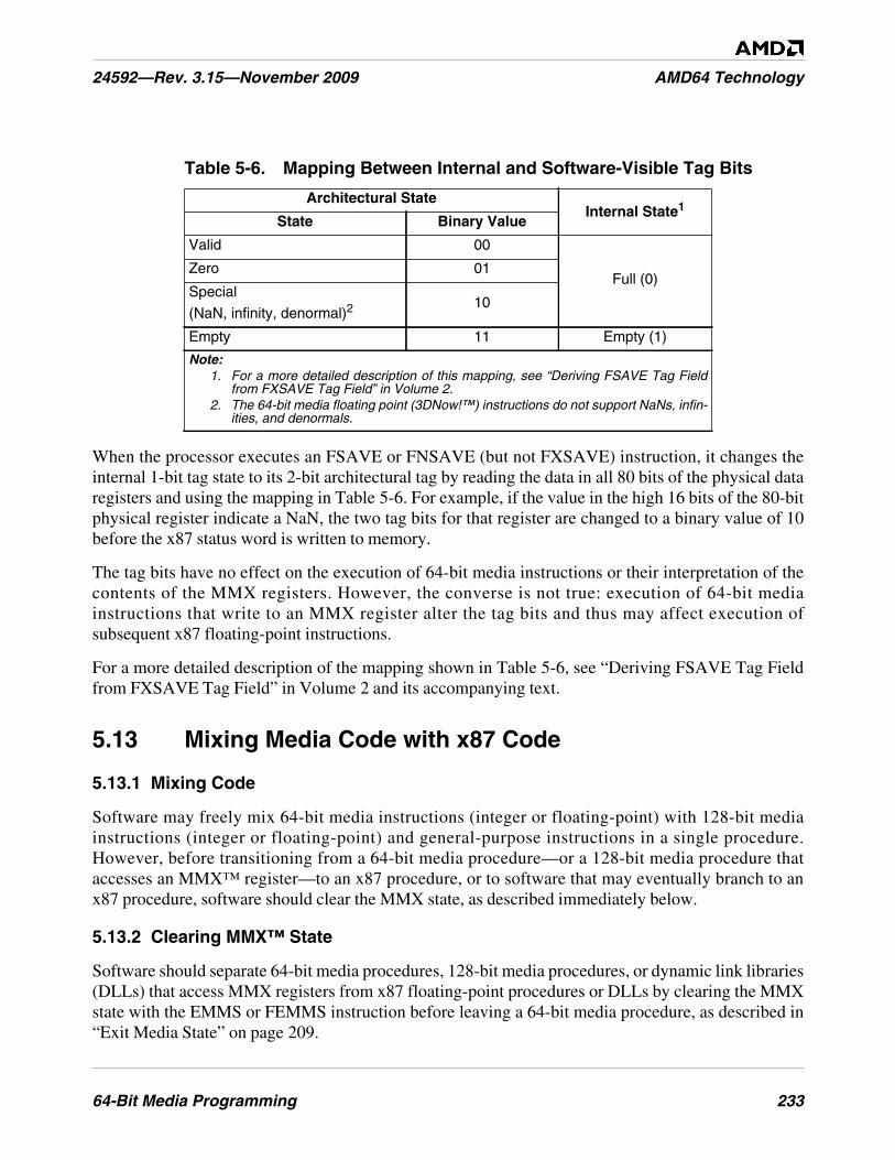
64-Bit Media Programming 233
24592—Rev. 3.15—November 2009 AMD64 Technology
When the processor executes an FSAVE or FNSAVE (but not FXSAVE) instruction, it changes theinternal 1-bit tag state to its 2-bit architectural tag by reading the data in all 80 bits of the physical dataregisters and using the mapping in Table 5-6. For example, if the value in the high 16 bits of the 80-bitphysical register indicate a NaN, the two tag bits for that register are changed to a binary value of 10before the x87 status word is written to memory.
The tag bits have no effect on the execution of 64-bit media instructions or their interpretation of thecontents of the MMX registers. However, the converse is not true: execution of 64-bit mediainstructions that write to an MMX register alter the tag bits and thus may affect execution ofsubsequent x87 floating-point instructions.
For a more detailed description of the mapping shown in Table 5-6, see “Deriving FSAVE Tag Fieldfrom FXSAVE Tag Field” in Volume 2 and its accompanying text.
5.13 Mixing Media Code with x87 Code
5.13.1 Mixing Code
Software may freely mix 64-bit media instructions (integer or floating-point) with 128-bit mediainstructions (integer or floating-point) and general-purpose instructions in a single procedure.However, before transitioning from a 64-bit media procedure—or a 128-bit media procedure thataccesses an MMX™ register—to an x87 procedure, or to software that may eventually branch to anx87 procedure, software should clear the MMX state, as described immediately below.
5.13.2 Clearing MMX™ State
Software should separate 64-bit media procedures, 128-bit media procedures, or dynamic link libraries(DLLs) that access MMX registers from x87 floating-point procedures or DLLs by clearing the MMXstate with the EMMS or FEMMS instruction before leaving a 64-bit media procedure, as described in“Exit Media State” on page 209.
Table 5-6. Mapping Between Internal and Software-Visible Tag Bits
Architectural StateInternal State1
State Binary Value
Valid 00
Full (0)Zero 01
Special
(NaN, infinity, denormal)210
Empty 11 Empty (1)
Note:1. For a more detailed description of this mapping, see “Deriving FSAVE Tag Field
from FXSAVE Tag Field” in Volume 2.2. The 64-bit media floating point (3DNow!™) instructions do not support NaNs, infin-
ities, and denormals.
234 64-Bit Media Programming
AMD64 Technology 24592—Rev. 3.15—November 2009
The 64-bit media instructions and x87 floating-point instructions interpret the contents of their aliasedMMX and x87 registers differently. Because of this, software should not exchange register databetween 64-bit media and x87 floating-point procedures, or use conditional branches at the end ofloops that might jump to code of the other type. Software must not rely on the contents of the aliasedMMX and x87 registers across such code-type transitions. If a transition to an x87 procedure occursfrom a 64-bit media procedure that does not clear the MMX state, the x87 stack may overflow.
5.14 State-Saving
5.14.1 Saving and Restoring State
In general, system software should save and restore MMX™ and x87 state between task switches orother interventions in the execution of 64-bit media procedures. Virtually all modern operatingsystems running on x86 processors implement preemptive multitasking that handle saving andrestoring of state across task switches, independent of hardware task-switch support.
No changes are needed to the x87 register-saving performed by 32-bit operating systems, exceptionhandlers, or device drivers. The same support provided in a 32-bit operating system’s device-not-available (#NM) exception handler by any of the x87-register save/restore instructions describedbelow also supports saving and restoring the MMX registers.
However, application procedures are also free to save and restore MMX and x87 state at any time theydeem useful.
5.14.2 State-Saving Instructions
Software running at any privilege level may save and restore 64-bit media and x87 state by executingthe FSAVE, FNSAVE, or FXSAVE instruction. Alternatively, software may use move instructions forsaving only the contents of the MMX registers, rather than the complete 64-bit media and x87 state.For example, when saving MMX register values, use eight MOVQ instructions.
FSAVE/FNSAVE and FRSTOR Instructions. The FSAVE, FNSAVE, and FRSTOR instructions aredescribed in “Save and Restore 64-Bit Media and x87 State” on page 223. After saving state withFSAVE or FNSAVE, the tag bits for all MMX and x87 registers are changed to empty and thusavailable for a new procedure. Thus, FSAVE and FNSAVE also perform the state-clearing function ofEMMS or FEMMS.
FXSAVE and FXRSTOR Instructions. The FSAVE, FNSAVE, and FRSTOR instructions aredescribed in “Save and Restore 128-Bit, 64-Bit, and x87 State” on page 223. The FXSAVE andFXRSTOR instructions execute faster than FSAVE/FNSAVE and FRSTOR because they do not saveand restore the x87 error pointers (described in “Pointers and Opcode State” on page 247) except in therelatively rare cases in which the exception-summary (ES) bit in the x87 status word (register imagefor FXSAVE, memory image for FXRSTOR) is set to 1, indicating that an unmasked x87 exceptionhas occurred.
64-Bit Media Programming 235
24592—Rev. 3.15—November 2009 AMD64 Technology
Unlike FSAVE and FNSAVE, however, FXSAVE does not alter the tag bits (thus, it does not performthe state-clearing function of EMMS or FEMMS). The state of the saved MMX and x87 registers isretained, thus indicating that the registers may still be valid (or whatever other value the tag bitsindicated prior to the save). To invalidate the contents of the MMX and x87 registers after FXSAVE,software must explicitly execute an FINIT instruction. Also, FXSAVE (like FNSAVE) and FXRSTORdo not check for pending unmasked x87 floating-point exceptions. An FWAIT instruction can be usedfor this purpose.
For details about the FXSAVE and FXRSTOR memory formats, see “Media and x87 Processor State”in Volume 2.
5.15 Performance Considerations
In addition to typical code optimization techniques, such as those affecting loops and the inlining offunction calls, the following considerations may help improve the performance of applicationprograms written with 64-bit media instructions.
These are implementation-independent performance considerations. Other considerations depend onthe hardware implementation. For information about such implementation-dependent considerationsand for more information about application performance in general, see the data sheets and thesoftware-optimization guides relating to particular hardware implementations.
5.15.1 Use Small Operand Sizes
The performance advantages available with 64-bit media operations is to some extent a function of thedata sizes operated upon. The smaller the data size, the more data elements that can be packed intosingle 64-bit vectors. The parallelism of computation increases as the number of elements per vectorincreases.
5.15.2 Reorganize Data for Parallel Operations
Much of the performance benefit from the 64-bit media instructions comes from the parallelisminherent in vector operations. It can be advantageous to reorganize data before performing arithmeticoperations so that its layout after reorganization maximizes the parallelism of the arithmeticoperations.
The speed of memory access is particularly important for certain types of computation, such asgraphics rendering, that depend on the regularity and locality of data-memory accesses. For example,in matrix operations, performance is high when operating on the rows of the matrix, because row bytesare contiguous in memory, but lower when operating on the columns of the matrix, because columnbytes are not contiguous in memory and accessing them can result in cache misses. To improveperformance for operations on such columns, the matrix should first be transposed. Suchtranspositions can, for example, be done using a sequence of unpacking or shuffle instructions.
236 64-Bit Media Programming
AMD64 Technology 24592—Rev. 3.15—November 2009
5.15.3 Remove Branches
Branch can be replaced with 64-bit media instructions that simulate predicated execution orconditional moves, as described in “Branch Removal” on page 198. Where possible, break longdependency chains into several shorter dependency chains which can be executed in parallel. This isespecially important for floating-point instructions because of their longer latencies.
5.15.4 Align Data
Data alignment is particularly important for performance when data written by one instruction is readby a subsequent instruction soon after the write, or when accessing streaming (non-temporal) data—data that will not be reused and therefore should not be cached. These cases may occur frequently in64-bit media procedures.
Accesses to data stored at unaligned locations may benefit from on-the-fly software alignment or fromrepetition of data at different alignment boundaries, as required by different loops that process the data.
5.15.5 Organize Data for Cacheability
Pack small data structures into cache-line-size blocks. Organize frequently accessed constants andcoefficients into cache-line-size blocks and prefetch them. Procedures that access data arranged inmemory-bus-sized blocks, or memory-burst-sized blocks, can make optimum use of the availablememory bandwidth.
For data that will be used only once in a procedure, consider using non-cacheable memory. Accesses tosuch memory are not burdened by the overhead of cache protocols.
5.15.6 Prefetch Data
Media applications typically operate on large data sets. Because of this, they make intensive use of thememory bus. Memory latency can be substantially reduced—especially for data that will be used onlyonce—by prefetching such data into various levels of the cache hierarchy. Software can use thePREFETCHx instructions very effectively in such cases, as described in “Cache and MemoryManagement” on page 66.
Some of the best places to use prefetch instructions are inside loops that process large amounts of data.If the loop goes through less than one cache line of data per iteration, partially unroll the loop to obtainmultiple iterations of the loop within a cache line. Try to use virtually all of the prefetched data. Thisusually requires unit-stride memory accesses—those in which all accesses are to contiguous memorylocations.
5.15.7 Retain Intermediate Results in MMX™ Registers
Keep intermediate results in the MMX registers as much as possible, especially if the intermediateresults are used shortly after they have been produced. Avoid spilling intermediate results to memoryand reusing them shortly thereafter.
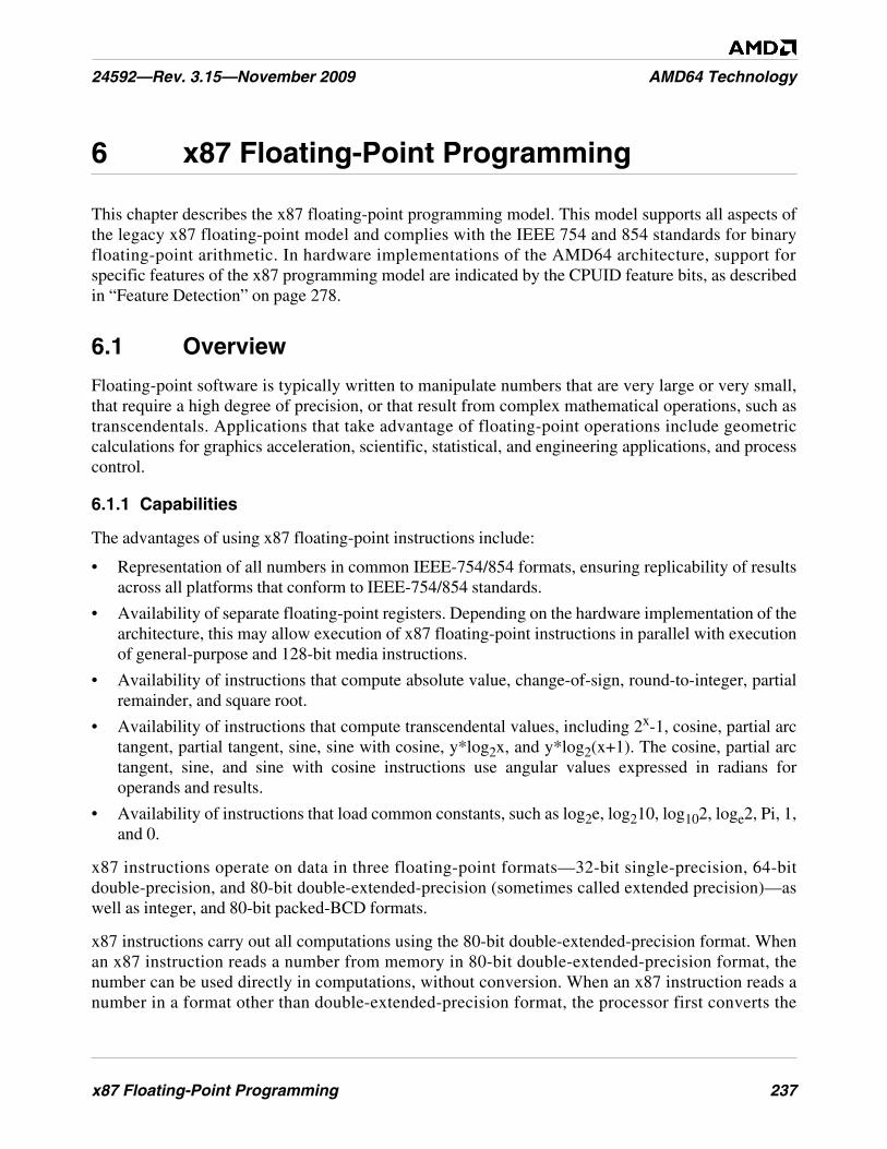
x87 Floating-Point Programming 237
24592—Rev. 3.15—November 2009 AMD64 Technology
6 x87 Floating-Point Programming
This chapter describes the x87 floating-point programming model. This model supports all aspects ofthe legacy x87 floating-point model and complies with the IEEE 754 and 854 standards for binaryfloating-point arithmetic. In hardware implementations of the AMD64 architecture, support forspecific features of the x87 programming model are indicated by the CPUID feature bits, as describedin “Feature Detection” on page 278.
6.1 Overview
Floating-point software is typically written to manipulate numbers that are very large or very small,that require a high degree of precision, or that result from complex mathematical operations, such astranscendentals. Applications that take advantage of floating-point operations include geometriccalculations for graphics acceleration, scientific, statistical, and engineering applications, and processcontrol.
6.1.1 Capabilities
The advantages of using x87 floating-point instructions include:
• Representation of all numbers in common IEEE-754/854 formats, ensuring replicability of resultsacross all platforms that conform to IEEE-754/854 standards.
• Availability of separate floating-point registers. Depending on the hardware implementation of thearchitecture, this may allow execution of x87 floating-point instructions in parallel with executionof general-purpose and 128-bit media instructions.
• Availability of instructions that compute absolute value, change-of-sign, round-to-integer, partialremainder, and square root.
• Availability of instructions that compute transcendental values, including 2x-1, cosine, partial arctangent, partial tangent, sine, sine with cosine, y*log2x, and y*log2(x+1). The cosine, partial arctangent, sine, and sine with cosine instructions use angular values expressed in radians foroperands and results.
• Availability of instructions that load common constants, such as log2e, log210, log102, loge2, Pi, 1,and 0.
x87 instructions operate on data in three floating-point formats—32-bit single-precision, 64-bitdouble-precision, and 80-bit double-extended-precision (sometimes called extended precision)—aswell as integer, and 80-bit packed-BCD formats.
x87 instructions carry out all computations using the 80-bit double-extended-precision format. Whenan x87 instruction reads a number from memory in 80-bit double-extended-precision format, thenumber can be used directly in computations, without conversion. When an x87 instruction reads anumber in a format other than double-extended-precision format, the processor first converts the

238 x87 Floating-Point Programming
AMD64 Technology 24592—Rev. 3.15—November 2009
number into double-extended-precision format. The processor can convert numbers back to specificformats, or leave them in double-extended-precision format when writing them to memory.
Most x87 operations for addition, subtraction, multiplication, and division specify two sourceoperands, the first of which is replaced by the result. Instructions for subtraction and division havereverse forms which swap the ordering of operands.
6.1.2 Origins
In 1979, AMD introduced the first floating-point coprocessor for microprocessors—the AM9511arithmetic circuit. This coprocessor performed 32-bit floating-point operations under microprocessorcontrol. In 1980, AMD introduced the AM9512, which performed 64-bit floating-point operations.These coprocessors were second-sourced as the 8231 and 8232 coprocessors. Before then,programmers working with general-purpose microprocessors had to use much slower, vendor-suppliedsoftware libraries for their floating-point needs.
In 1985, the Institute of Electrical and Electronics Engineers published the IEEE Standard for BinaryFloating-Point Arithmetic, also referred to as the ANSI/IEEE Std 754-1985 standard, or IEEE 754.This standard defines the data types, operations, and exception-handling methods that are the basis forthe x87 floating-point technology implemented in the legacy x86 architecture. In 1987, the IEEEpublished a more general radix-independent version of that standard, called the ANSI/IEEE Std 854-1987 standard, or IEEE 854 for short. The AMD64 architecture complies with both the IEEE 754 andIEEE 854 standards.
6.1.3 Compatibility
x87 floating-point instructions can be executed in any of the architecture’s operating modes. Existingx87 binary programs run in legacy and compatibility modes without modification. The supportprovided by the AMD64 architecture for such binaries is identical to that provided by legacy x86architectures.
To run in 64-bit mode, x87 floating-point programs must be recompiled. The recompilation has no sideeffects on such programs, other than to make available the extended general-purpose registers and 64-bit virtual address space.
6.2 Registers
Operands for the x87 instructions are located in x87 registers or memory. Figure 6-1 on page 239shows an overview of the x87 registers.
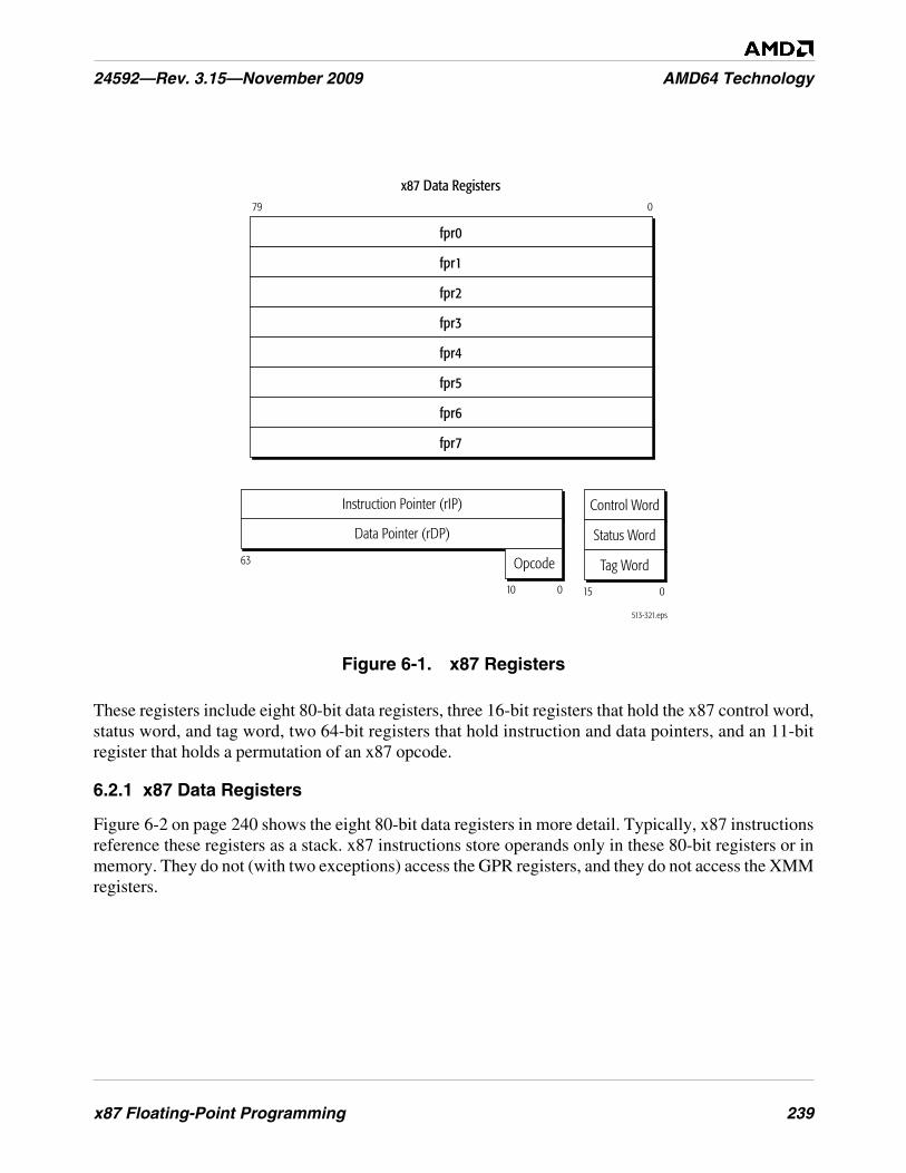
x87 Floating-Point Programming 239
24592—Rev. 3.15—November 2009 AMD64 Technology
Figure 6-1. x87 Registers
These registers include eight 80-bit data registers, three 16-bit registers that hold the x87 control word,status word, and tag word, two 64-bit registers that hold instruction and data pointers, and an 11-bitregister that holds a permutation of an x87 opcode.
6.2.1 x87 Data Registers
Figure 6-2 on page 240 shows the eight 80-bit data registers in more detail. Typically, x87 instructionsreference these registers as a stack. x87 instructions store operands only in these 80-bit registers or inmemory. They do not (with two exceptions) access the GPR registers, and they do not access the XMMregisters.
Tag Word
Status Word
Control Word
513-321.eps
x87 Data Registers79 0
fpr0
fpr1
fpr2
fpr3
fpr4
fpr5
fpr6
fpr7
015
63
010
Instruction Pointer (rIP)
Data Pointer (rDP)
Tag Word
Status Word
Control Word
Opcode
240 x87 Floating-Point Programming
AMD64 Technology 24592—Rev. 3.15—November 2009
Figure 6-2. x87 Physical and Stack Registers
Stack Organization. The bank of eight physical data registers, FPR0–FPR7, are organized internallyas a stack, ST(0)–ST(7). The stack functions like a circular modulo-8 buffer. The stack top can be setby software to start at any register position in the bank. Many instructions access the top of stack aswell as individual registers relative to the top of stack.
Stack Pointer. Bits 13–11 of the x87 status word (“x87 Status Word Register (FSW)” on page 241)are the top-of-stack pointer (TOP). The TOP specifies the mapping of the stack registers onto thephysical registers. The TOP contains the physical-register index of the location of the top of stack,ST(0). Instructions that load operands from memory into an x87 register first decrement the stackpointer and then copy the operand (often with conversion to the double-extended-precision format)from memory into the decremented top-of-stack register. Instructions that store operands from an x87register to memory copy the operand (often with conversion from the double-extended-precisionformat) in the top-of-stack register to memory and then increment the stack pointer.
Figure 6-2 shows the mapping between stack registers and physical registers when the TOP has thevalue 2. Modulo-8 wraparound addressing is used. Pushing a new element onto this stack—forexample with the FLDZ (floating-point load +0.0) instruction—decrements the TOP to 1, so thatST(0) refers to FPR1, and the new top-of-stack is loaded with +0.0.
The architecture provides alternative versions of many instructions that either modify or do not modifythe TOP as a side effect. For example, FADDP (floating-point add and pop) behaves exactly likeFADD (floating-point add), except that it pops the stack after completion. Programs that use the x87registers as a flat register file rather than as a stack would use non-popping versions of instructions toensure that the TOP remains unchanged. However, loads (pushes) without corresponding pops cancause the stack to overflow, which occurs when a value is pushed or loaded into an x87 register that is
513-134.eps
79 0
13 11
fpr0
TOP
x87StatusWord fpr1
fpr2
fpr3
fpr4
fpr5
fpr6
fpr7
ST(6)
ST(7)
ST(0)
ST(1)
ST(2)
ST(3)
ST(4)
ST(5)
x87 Floating-Point Programming 241
24592—Rev. 3.15—November 2009 AMD64 Technology
not empty (as indicated by the register’s tag bits). To prevent overflow, the FXCH (floating-pointexchange) instruction can be used to access stack registers, giving the appearance of a flat register file,but all x87 programs must be aware of the register file’s stack organization.
The FINCSTP and FDECSTP instructions can be used to increment and decrement, respectively, theTOP, modulo-8, allowing the stack top to wrap around to the bottom of the eight-register file whenincremented beyond the top of the file, or to wrap around to the top of the register file whendecremented beyond the bottom of the file. Neither the x87 tag word nor the contents of the floating-point stack itself is updated when these instructions are used.
6.2.2 x87 Status Word Register (FSW)
The 16-bit x87 status word register contains information about the state of the floating-point unit,including the top-of-stack pointer (TOP), four condition-code bits, exception-summary flag, stack-fault flag, and six x87 floating-point exception flags. Figure 6-3 on page 242 shows the format of thisregister. All bits can be read and written, however values written to the B and ES bits (bits 15 and 7) areignored.
The FRSTOR and FXRSTOR instructions load the status word from memory. The FSTSW, FNSTSW,FSAVE, FNSAVE, FXSAVE, FSTENV, and FNSTENV instructions store the status word to memory.The FCLEX and FNCLEX instructions clear the exception flags. The FINIT and FNINIT instructionsclear all bits in the status-word.
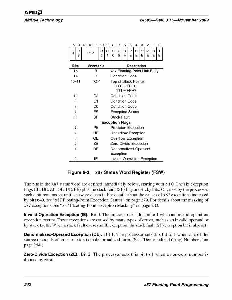
242 x87 Floating-Point Programming
AMD64 Technology 24592—Rev. 3.15—November 2009
Figure 6-3. x87 Status Word Register (FSW)
The bits in the x87 status word are defined immediately below, starting with bit 0. The six exceptionflags (IE, DE, ZE, OE, UE, PE) plus the stack fault (SF) flag are sticky bits. Once set by the processor,such a bit remains set until software clears it. For details about the causes of x87 exceptions indicatedby bits 6–0, see “x87 Floating-Point Exception Causes” on page 279. For details about the masking ofx87 exceptions, see “x87 Floating-Point Exception Masking” on page 283.
Invalid-Operation Exception (IE). Bit 0. The processor sets this bit to 1 when an invalid-operationexception occurs. These exceptions are caused by many types of errors, such as an invalid operand orby stack faults. When a stack fault causes an IE exception, the stack fault (SF) exception bit is also set.
Denormalized-Operand Exception (DE). Bit 1. The processor sets this bit to 1 when one of thesource operands of an instruction is in denormalized form. (See “Denormalized (Tiny) Numbers” onpage 254.)
Zero-Divide Exception (ZE). Bit 2. The processor sets this bit to 1 when a non-zero number isdivided by zero.
15 14 13 12 11 10 9 8 7 6 5 4 3 2 1 0
BC3
TOPC2
C1
C0
ES
SF
PE
UE
OE
ZE
DE
IE
Bits Mnemonic Description
15 B x87 Floating-Point Unit Busy14 C3 Condition Code
13–11 TOP Top of Stack Pointer000 = FPR0111 = FPR7
10 C2 Condition Code9 C1 Condition Code8 C0 Condition Code7 ES Exception Status6 SF Stack Fault
Exception Flags5 PE Precision Exception4 UE Underflow Exception3 OE Overflow Exception2 ZE Zero-Divide Exception1 DE Denormalized-Operand
Exception0 IE Invalid-Operation Exception

x87 Floating-Point Programming 243
24592—Rev. 3.15—November 2009 AMD64 Technology
Overflow Exception (OE). Bit 3. The processor sets this bit to 1 when the absolute value of arounded result is larger than the largest representable normalized floating-point number for thedestination format. (See “Normalized Numbers” on page 254.)
Underflow Exception (UE). Bit 4. The processor sets this bit to 1 when the absolute value of arounded non-zero result is too small to be represented as a normalized floating-point number for thedestination format. (See “Normalized Numbers” on page 254.)
The underflow exception has an unusual behavior. When masked by the UM bit (bit 4 of the x87control word), the processor only reports a UE exception if the UE occurs together with a precisionexception (PE).
Precision Exception (PE). Bit 5. The processor sets this bit to 1 when a floating-point result, afterrounding, differs from the infinitely precise result and thus cannot be represented exactly in thespecified destination format. The PE exception is also called the inexact-result exception.
Stack Fault (SF). Bit 6. The processor sets this bit to 1 when a stack overflow (due to a push or loadinto a non-empty stack register) or stack underflow (due to referencing an empty stack register) occursin the x87 stack-register file. When either of these conditions occur, the processor also sets the invalid-operation exception (IE) flag, and the processor distinguishes overflow from underflow by writing thecondition-code 1 (C1) bit (C1 = 1 for overflow, C1 = 0 for underflow). Unlike the flags for the otherx87 exceptions, the SF flag does not have a corresponding mask bit in the x87 control word.
If, subsequent to the instruction that caused the SF bit to be set, a second invalid-operation exception(IE) occurs due to an invalid operand in an arithmetic instruction (i.e., not a stack fault), and if softwarehas not cleared the SF bit between the two instructions, the SF bit will remain set.
Exception Status (ES). Bit 7. The processor calculates the value of this bit at each instructionboundary and sets the bit to 1 when one or more unmasked floating-point exceptions occur. If the ESbit has already been set by the action of some prior instruction, the processor invokes the #MFexception handler when the next non-control x87 or 64-bit media instruction is executed. (See“Control” on page 273 for a definition of control instructions).
The ES bit can be written, but the written value is ignored. Like the SF bit, the ES bit does not have acorresponding mask bit in the x87 control word.
Top-of-Stack Pointer (TOP). Bits 13–11. The TOP contains the physical register index of thelocation of the top of stack, ST(0). It thus specifies the mapping of the x87 stack registers,ST(0)–ST(7), onto the x87 physical registers, FPR0–FPR7. The processor changes the TOP during anyinstructions that pushes or pops the stack. For details on how the stack works, see “StackOrganization” on page 240.
Condition Codes (C3–C0). Bits 14 and 10–8. The processor sets these bits according to the result ofarithmetic, compare, and other instructions. In certain cases, other status-word flags can be usedtogether with the condition codes to determine the result of an operation, including stack overflow,stack underflow, sign, least-significant quotient bits, last-rounding direction, and out-of-range
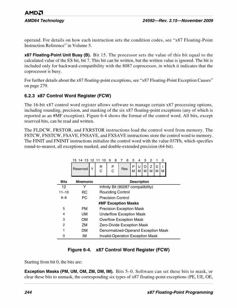
244 x87 Floating-Point Programming
AMD64 Technology 24592—Rev. 3.15—November 2009
operand. For details on how each instruction sets the condition codes, see “x87 Floating-PointInstruction Reference” in Volume 5.
x87 Floating-Point Unit Busy (B). Bit 15. The processor sets the value of this bit equal to thecalculated value of the ES bit, bit 7. This bit can be written, but the written value is ignored. The bit isincluded only for backward-compatibility with the 8087 coprocessor, in which it indicates that thecoprocessor is busy.
For further details about the x87 floating-point exceptions, see “x87 Floating-Point Exception Causes”on page 279.
6.2.3 x87 Control Word Register (FCW)
The 16-bit x87 control word register allows software to manage certain x87 processing options,including rounding, precision, and masking of the six x87 floating-point exceptions (any of which isreported as an #MF exception). Figure 6-4 shows the format of the control word. All bits, exceptreserved bits, can be read and written.
The FLDCW, FRSTOR, and FXRSTOR instructions load the control word from memory. TheFSTCW, FNSTCW, FSAVE, FNSAVE, and FXSAVE instructions store the control word to memory.The FINIT and FNINIT instructions initialize the control word with the value 037Fh, which specifiesround-to-nearest, all exceptions masked, and double-extended precision (64-bit).
Figure 6-4. x87 Control Word Register (FCW)
Starting from bit 0, the bits are:
Exception Masks (PM, UM, OM, ZM, DM, IM). Bits 5–0. Software can set these bits to mask, orclear these bits to unmask, the corresponding six types of x87 floating-point exceptions (PE, UE, OE,
15 14 13 12 11 10 9 8 7 6 5 4 3 2 1 0
Reserved YRC
PC
ResPM
UM
OM
ZM
DM
IM
Bits Mnemonic Description
12 Y Infinity Bit (80287 compatibility)11–10 RC Rounding Control9–8 PC Precision Control
#MF Exception Masks5 PM Precision Exception Mask4 UM Underflow Exception Mask3 OM Overflow Exception Mask2 ZM Zero-Divide Exception Mask1 DM Denormalized-Operand Exception Mask0 IM Invalid-Operation Exception Mask
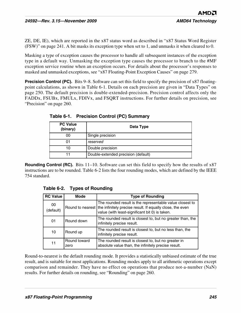
x87 Floating-Point Programming 245
24592—Rev. 3.15—November 2009 AMD64 Technology
ZE, DE, IE), which are reported in the x87 status word as described in “x87 Status Word Register(FSW)” on page 241. A bit masks its exception type when set to 1, and unmasks it when cleared to 0.
Masking a type of exception causes the processor to handle all subsequent instances of the exceptiontype in a default way. Unmasking the exception type causes the processor to branch to the #MFexception service routine when an exception occurs. For details about the processor’s responses tomasked and unmasked exceptions, see “x87 Floating-Point Exception Causes” on page 279.
Precision Control (PC). Bits 9–8. Software can set this field to specify the precision of x87 floating-point calculations, as shown in Table 6-1. Details on each precision are given in “Data Types” onpage 250. The default precision is double-extended-precision. Precision control affects only theFADDx, FSUBx, FMULx, FDIVx, and FSQRT instructions. For further details on precision, see“Precision” on page 260.
Rounding Control (RC). Bits 11–10. Software can set this field to specify how the results of x87instructions are to be rounded. Table 6-2 lists the four rounding modes, which are defined by the IEEE754 standard.
Round-to-nearest is the default rounding mode. It provides a statistically unbiased estimate of the trueresult, and is suitable for most applications. Rounding modes apply to all arithmetic operations exceptcomparison and remainder. They have no effect on operations that produce not-a-number (NaN)results. For further details on rounding, see “Rounding” on page 260.
Table 6-1. Precision Control (PC) Summary
PC Value(binary)
Data Type
00 Single precision
01 reserved
10 Double precision
11 Double-extended precision (default)
Table 6-2. Types of Rounding
RC Value Mode Type of Rounding
00(default)
Round to nearestThe rounded result is the representable value closest tothe infinitely precise result. If equally close, the evenvalue (with least-significant bit 0) is taken.
01 Round downThe rounded result is closest to, but no greater than, theinfinitely precise result.
10 Round upThe rounded result is closest to, but no less than, theinfinitely precise result.
11Round towardzero
The rounded result is closest to, but no greater inabsolute value than, the infinitely precise result.
246 x87 Floating-Point Programming
AMD64 Technology 24592—Rev. 3.15—November 2009
Infinity Bit (Y). Bit 12. This bit is obsolete. It can be read and written, but the value has no meaning.On pre-386 processor implementations, the bit specified the affine (Y = 1) or projective (Y = 0)infinity. The AMD64 architecture uses only the affine infinity, which specifies distinct positive andnegative infinity values.
6.2.4 x87 Tag Word Register (FTW)
The x87 tag word register contains a 2-bit tag field for each x87 physical data register. These tag fieldscharacterize the register’s data. Figure 6-5 shows the format of the tag word.
Figure 6-5. x87 Tag Word Register (FTW)
In the memory image saved by the instructions described in “x87 Environment” on page 248, each x87physical data register has two tag bits which are encoded according to the Tag Values shown inFigure 6-5. Internally, the hardware may maintain only a single bit that indicates whether theassociated register is empty or full. The mapping between such a 1-bit internal tag and the 2-bitsoftware-visible architectural representation saved in memory is shown in Table 6-3 on page 246. Insuch a mapping, whenever software saves the tag word, the processor expands the internal 1-bit tagstate to the 2-bit architectural representation by examining the contents of the x87 registers, asdescribed in “128-Bit, 64-Bit, and x87 Programming” in Volume 2.
The FINIT and FNINIT instructions write the tag word so that it specifies all floating-point registers asempty. Execution of 64-bit media instructions that write to an MMX™ register alter the tag bits by
Table 6-3. Mapping Between Internal and Software-Visible Tag Bits
Architectural State (Software-Visible)Hardware State
State Bit Value
Valid 00
FullZero 01
Special(NaN, infinity, denormal, or unsupported)
10
Empty 11 Empty
9 8 7 6 5 4 3 2 1 0101112131415
TAG(FPR6)
TAG(FPR7)
TAG(FPR4)
TAG(FPR5)
TAG(FPR2)
TAG(FPR3)
TAG(FPR0)
TAG(FPR1)
Tag Values00 = Valid01 = Zero10 = Special11 = Empty
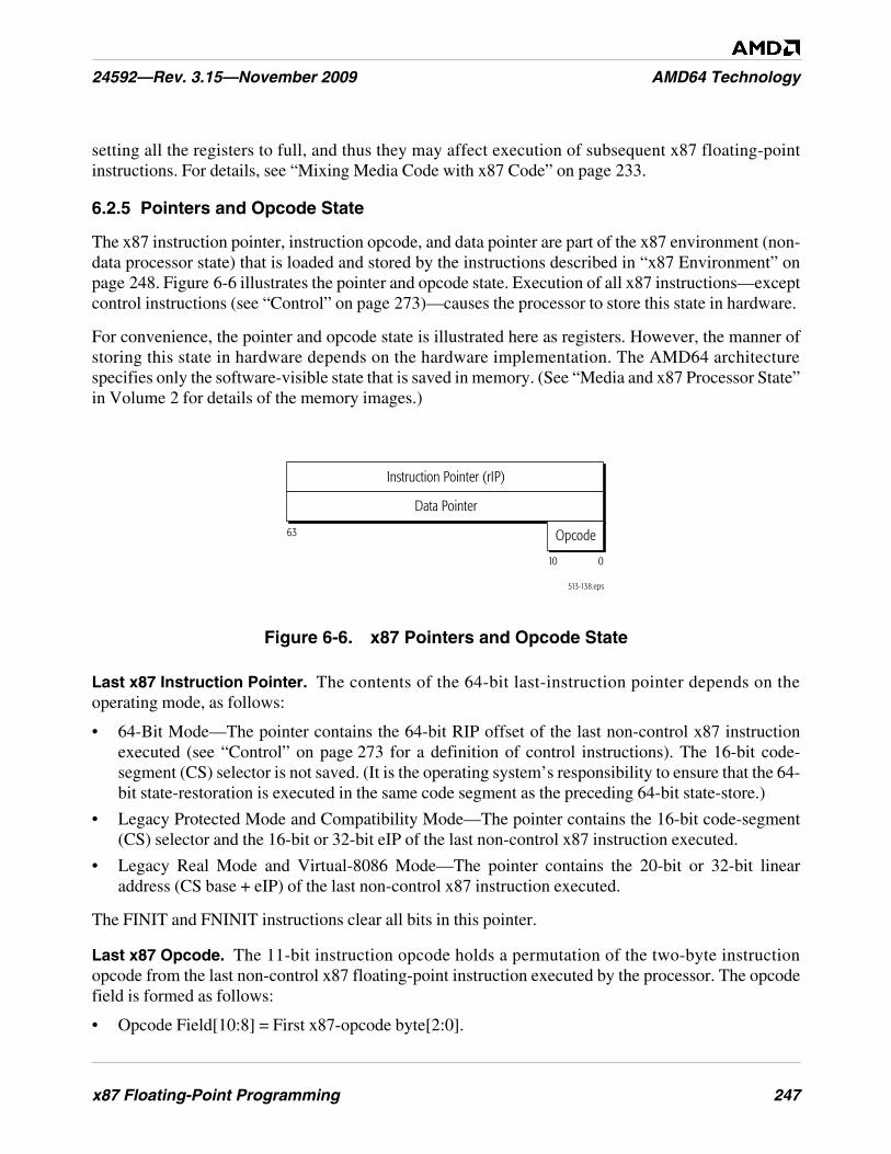
x87 Floating-Point Programming 247
24592—Rev. 3.15—November 2009 AMD64 Technology
setting all the registers to full, and thus they may affect execution of subsequent x87 floating-pointinstructions. For details, see “Mixing Media Code with x87 Code” on page 233.
6.2.5 Pointers and Opcode State
The x87 instruction pointer, instruction opcode, and data pointer are part of the x87 environment (non-data processor state) that is loaded and stored by the instructions described in “x87 Environment” onpage 248. Figure 6-6 illustrates the pointer and opcode state. Execution of all x87 instructions—exceptcontrol instructions (see “Control” on page 273)—causes the processor to store this state in hardware.
For convenience, the pointer and opcode state is illustrated here as registers. However, the manner ofstoring this state in hardware depends on the hardware implementation. The AMD64 architecturespecifies only the software-visible state that is saved in memory. (See “Media and x87 Processor State”in Volume 2 for details of the memory images.)
Figure 6-6. x87 Pointers and Opcode State
Last x87 Instruction Pointer. The contents of the 64-bit last-instruction pointer depends on theoperating mode, as follows:
• 64-Bit Mode—The pointer contains the 64-bit RIP offset of the last non-control x87 instructionexecuted (see “Control” on page 273 for a definition of control instructions). The 16-bit code-segment (CS) selector is not saved. (It is the operating system’s responsibility to ensure that the 64-bit state-restoration is executed in the same code segment as the preceding 64-bit state-store.)
• Legacy Protected Mode and Compatibility Mode—The pointer contains the 16-bit code-segment(CS) selector and the 16-bit or 32-bit eIP of the last non-control x87 instruction executed.
• Legacy Real Mode and Virtual-8086 Mode—The pointer contains the 20-bit or 32-bit linearaddress (CS base + eIP) of the last non-control x87 instruction executed.
The FINIT and FNINIT instructions clear all bits in this pointer.
Last x87 Opcode. The 11-bit instruction opcode holds a permutation of the two-byte instructionopcode from the last non-control x87 floating-point instruction executed by the processor. The opcodefield is formed as follows:
• Opcode Field[10:8] = First x87-opcode byte[2:0].
513-138.eps
63
010
Instruction Pointer (rIP)
Data Pointer
Opcode
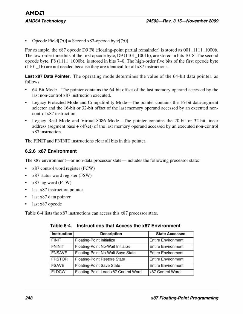
248 x87 Floating-Point Programming
AMD64 Technology 24592—Rev. 3.15—November 2009
• Opcode Field[7:0] = Second x87-opcode byte[7:0].
For example, the x87 opcode D9 F8 (floating-point partial remainder) is stored as 001_1111_1000b.The low-order three bits of the first opcode byte, D9 (1101_1001b), are stored in bits 10–8. The secondopcode byte, F8 (1111_1000b), is stored in bits 7–0. The high-order five bits of the first opcode byte(1101_1b) are not needed because they are identical for all x87 instructions.
Last x87 Data Pointer. The operating mode determines the value of the 64-bit data pointer, asfollows:
• 64-Bit Mode—The pointer contains the 64-bit offset of the last memory operand accessed by thelast non-control x87 instruction executed.
• Legacy Protected Mode and Compatibility Mode—The pointer contains the 16-bit data-segmentselector and the 16-bit or 32-bit offset of the last memory operand accessed by an executed non-control x87 instruction.
• Legacy Real Mode and Virtual-8086 Mode—The pointer contains the 20-bit or 32-bit linearaddress (segment base + offset) of the last memory operand accessed by an executed non-controlx87 instruction.
The FINIT and FNINIT instructions clear all bits in this pointer.
6.2.6 x87 Environment
The x87 environment—or non-data processor state—includes the following processor state:
• x87 control word register (FCW)
• x87 status word register (FSW)
• x87 tag word (FTW)
• last x87 instruction pointer
• last x87 data pointer
• last x87 opcode
Table 6-4 lists the x87 instructions can access this x87 processor state.
Table 6-4. Instructions that Access the x87 Environment
Instruction Description State Accessed
FINIT Floating-Point Initialize Entire Environment
FNINIT Floating-Point No-Wait Initialize Entire Environment
FNSAVE Floating-Point No-Wait Save State Entire Environment
FRSTOR Floating-Point Restore State Entire Environment
FSAVE Floating-Point Save State Entire Environment
FLDCW Floating-Point Load x87 Control Word x87 Control Word
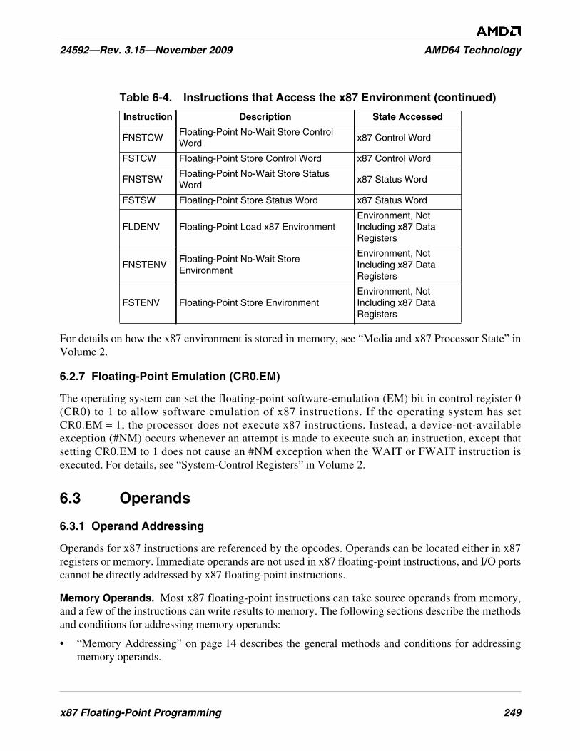
x87 Floating-Point Programming 249
24592—Rev. 3.15—November 2009 AMD64 Technology
For details on how the x87 environment is stored in memory, see “Media and x87 Processor State” inVolume 2.
6.2.7 Floating-Point Emulation (CR0.EM)
The operating system can set the floating-point software-emulation (EM) bit in control register 0(CR0) to 1 to allow software emulation of x87 instructions. If the operating system has setCR0.EM = 1, the processor does not execute x87 instructions. Instead, a device-not-availableexception (#NM) occurs whenever an attempt is made to execute such an instruction, except thatsetting CR0.EM to 1 does not cause an #NM exception when the WAIT or FWAIT instruction isexecuted. For details, see “System-Control Registers” in Volume 2.
6.3 Operands
6.3.1 Operand Addressing
Operands for x87 instructions are referenced by the opcodes. Operands can be located either in x87registers or memory. Immediate operands are not used in x87 floating-point instructions, and I/O portscannot be directly addressed by x87 floating-point instructions.
Memory Operands. Most x87 floating-point instructions can take source operands from memory,and a few of the instructions can write results to memory. The following sections describe the methodsand conditions for addressing memory operands:
• “Memory Addressing” on page 14 describes the general methods and conditions for addressingmemory operands.
FNSTCWFloating-Point No-Wait Store ControlWord
x87 Control Word
FSTCW Floating-Point Store Control Word x87 Control Word
FNSTSWFloating-Point No-Wait Store StatusWord
x87 Status Word
FSTSW Floating-Point Store Status Word x87 Status Word
FLDENV Floating-Point Load x87 EnvironmentEnvironment, NotIncluding x87 DataRegisters
FNSTENVFloating-Point No-Wait StoreEnvironment
Environment, NotIncluding x87 DataRegisters
FSTENV Floating-Point Store EnvironmentEnvironment, NotIncluding x87 DataRegisters
Table 6-4. Instructions that Access the x87 Environment (continued)
Instruction Description State Accessed
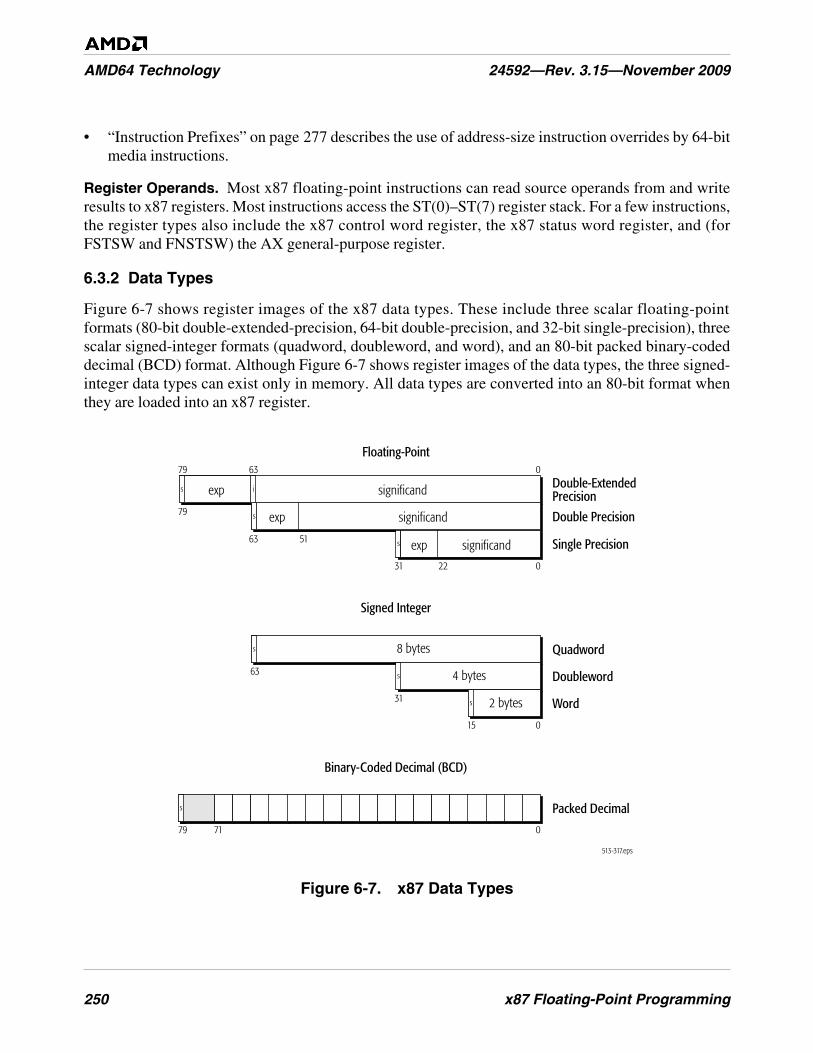
250 x87 Floating-Point Programming
AMD64 Technology 24592—Rev. 3.15—November 2009
• “Instruction Prefixes” on page 277 describes the use of address-size instruction overrides by 64-bitmedia instructions.
Register Operands. Most x87 floating-point instructions can read source operands from and writeresults to x87 registers. Most instructions access the ST(0)–ST(7) register stack. For a few instructions,the register types also include the x87 control word register, the x87 status word register, and (forFSTSW and FNSTSW) the AX general-purpose register.
6.3.2 Data Types
Figure 6-7 shows register images of the x87 data types. These include three scalar floating-pointformats (80-bit double-extended-precision, 64-bit double-precision, and 32-bit single-precision), threescalar signed-integer formats (quadword, doubleword, and word), and an 80-bit packed binary-codeddecimal (BCD) format. Although Figure 6-7 shows register images of the data types, the three signed-integer data types can exist only in memory. All data types are converted into an 80-bit format whenthey are loaded into an x87 register.
Figure 6-7. x87 Data Types
s
513-317.eps
63
31
31
22
15 0
0
0
Quadword
Doubleword
Words
s
s
Signed Integer
Binary-Coded Decimal (BCD)
Floating-Point
8 bytes
4 bytes
63
63
51
Double Precision
Single Precisions
s
2 bytes
79
79
079 71
Double-ExtendedPrecision
Packed Decimal
s i
significand
exp significand
exp significand
exp
s
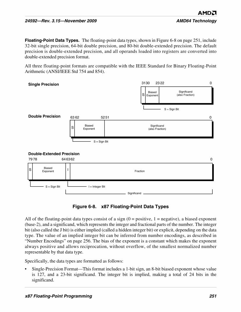
x87 Floating-Point Programming 251
24592—Rev. 3.15—November 2009 AMD64 Technology
Floating-Point Data Types. The floating-point data types, shown in Figure 6-8 on page 251, include32-bit single precision, 64-bit double precision, and 80-bit double-extended precision. The defaultprecision is double-extended precision, and all operands loaded into registers are converted intodouble-extended precision format.
All three floating-point formats are compatible with the IEEE Standard for Binary Floating-PointArithmetic (ANSI/IEEE Std 754 and 854).
Figure 6-8. x87 Floating-Point Data Types
All of the floating-point data types consist of a sign (0 = positive, 1 = negative), a biased exponent(base-2), and a significand, which represents the integer and fractional parts of the number. The integerbit (also called the J bit) is either implied (called a hidden integer bit) or explicit, depending on the datatype. The value of an implied integer bit can be inferred from number encodings, as described in“Number Encodings” on page 256. The bias of the exponent is a constant which makes the exponentalways positive and allows reciprocation, without overflow, of the smallest normalized numberrepresentable by that data type.
Specifically, the data types are formatted as follows:
• Single-Precision Format—This format includes a 1-bit sign, an 8-bit biased exponent whose valueis 127, and a 23-bit significand. The integer bit is implied, making a total of 24 bits in thesignificand.
063Double Precision
31 0Single Precision
079
22
S BiasedExponent
78
23
SBiased
Exponent
6364
5152
BiasedExponentS
Fraction
30
62
Double-Extended Precision
S = Sign Bit
S = Sign Bit
S = Sign Bit
I
62
I = Integer Bit
Significand(also Fraction)
Significand
Significand(also Fraction)
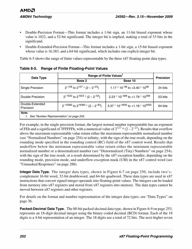
252 x87 Floating-Point Programming
AMD64 Technology 24592—Rev. 3.15—November 2009
• Double-Precision Format—This format includes a 1-bit sign, an 11-bit biased exponent whosevalue is 1023, and a 52-bit significand. The integer bit is implied, making a total of 53 bits in thesignificand.
• Double-Extended-Precision Format—This format includes a 1-bit sign, a 15-bit biased exponentwhose value is 16,383, and a 64-bit significand, which includes one explicit integer bit.
Table 6-5 shows the range of finite values representable by the three x87 floating-point data types.
For example, in the single-precision format, the largest normal number representable has an exponentof FEh and a significand of 7FFFFFh, with a numerical value of 2127 * (2 – 2–23). Results that overflowabove the maximum representable value return either the maximum representable normalized number(see “Normalized Numbers” on page 254) or infinity, with the sign of the true result, depending on therounding mode specified in the rounding control (RC) field of the x87 control word. Results thatunderflow below the minimum representable value return either the minimum representablenormalized number or a denormalized number (see “Denormalized (Tiny) Numbers” on page 254),with the sign of the true result, or a result determined by the x87 exception handler, depending on therounding mode, precision mode, and underflow-exception mask (UM) in the x87 control word (see“Unmasked Responses” on page 288).
Integer Data Type. The integer data types, shown in Figure 6-7 on page 250, include two’s-complement 16-bit word, 32-bit doubleword, and 64-bit quadword. These data types are used in x87instructions that convert signed integer operands into floating-point values. The integers can be loadedfrom memory into x87 registers and stored from x87 registers into memory. The data types cannot bemoved between x87 registers and other registers.
For details on the format and number-representation of the integer data types, see “Data Types” onpage 36.
Packed-Decimal Data Type. The 80-bit packed-decimal data type, shown in Figure 6-9 on page 253,represents an 18-digit decimal integer using the binary-coded decimal (BCD) format. Each of the 18digits is a 4-bit representation of an integer. The 18 digits use a total of 72 bits. The next-higher seven
Table 6-5. Range of Finite Floating-Point Values
Data TypeRange of Finite Values1
PrecisionBase 2 Base 10
Single Precision 2–126 to 2127 * (2 – 2–23) 1.17 * 10–38 to +3.40 * 1038 24 bits
Double Precision 2–1022 to 21023 * (2 – 2–52) 2.23 * 10–308 to +1.79 * 10308 53 bits
Double-ExtendedPrecision
2–16382 to 216383 * (2 – 2–63) 3.37 * 10–4932 to +1.18 * 104932 64 bits
Note:1. See “Number Representation” on page 253.
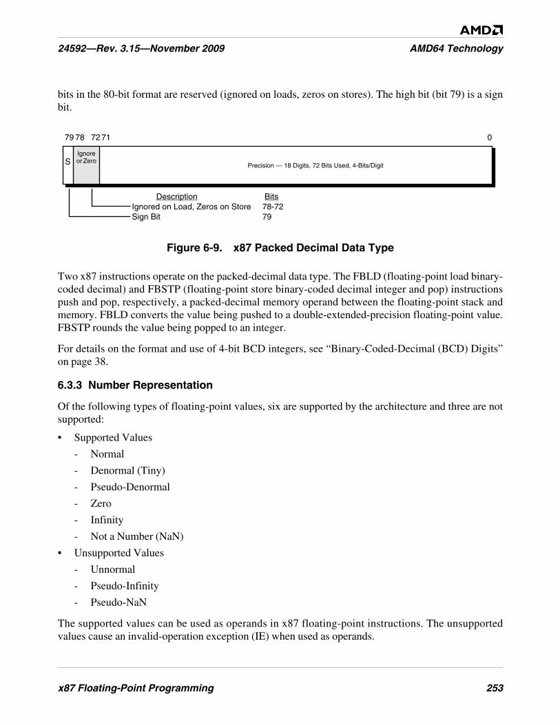
x87 Floating-Point Programming 253
24592—Rev. 3.15—November 2009 AMD64 Technology
bits in the 80-bit format are reserved (ignored on loads, zeros on stores). The high bit (bit 79) is a signbit.
Figure 6-9. x87 Packed Decimal Data Type
Two x87 instructions operate on the packed-decimal data type. The FBLD (floating-point load binary-coded decimal) and FBSTP (floating-point store binary-coded decimal integer and pop) instructionspush and pop, respectively, a packed-decimal memory operand between the floating-point stack andmemory. FBLD converts the value being pushed to a double-extended-precision floating-point value.FBSTP rounds the value being popped to an integer.
For details on the format and use of 4-bit BCD integers, see “Binary-Coded-Decimal (BCD) Digits”on page 38.
6.3.3 Number Representation
Of the following types of floating-point values, six are supported by the architecture and three are notsupported:
• Supported Values
- Normal
- Denormal (Tiny)
- Pseudo-Denormal
- Zero
- Infinity
- Not a Number (NaN)
• Unsupported Values
- Unnormal
- Pseudo-Infinity
- Pseudo-NaN
The supported values can be used as operands in x87 floating-point instructions. The unsupportedvalues cause an invalid-operation exception (IE) when used as operands.
079
Precision — 18 Digits, 72 Bits Used, 4-Bits/Digit
71
SIgnoreor Zero
Description BitsIgnored on Load, Zeros on Store 78-72Sign Bit 79
78 72
254 x87 Floating-Point Programming
AMD64 Technology 24592—Rev. 3.15—November 2009
In common engineering and scientific usage, floating-point numbers—also called real numbers—arerepresented in base (radix) 10. A non-zero number consists of a sign, a normalized significand, and asigned exponent, as in:
+2.71828 e0
Both large and small numbers are representable in this notation, subject to the limits of data-typeprecision. For example, a million in base-10 notation appears as +1.00000 e6 and -0.0000383 isrepresented as -3.83000 e-5. A non-zero number can always be written in normalized form—that is,with a leading non-zero digit immediately before the decimal point. Thus, a normalized significand inbase-10 notation is a number in the range [1,10). The signed exponent specifies the number ofpositions that the decimal point is shifted.
Unlike the common engineering and scientific usage described above, x87 floating-point numbers arerepresented in base (radix) 2. Like its base-10 counterpart, a normalized base-2 significand is writtenwith its leading non-zero digit immediately to the left of the radix point. In base-2 arithmetic, a non-zero digit is always a one, so the range of a binary significand is [1,2):
+1.fraction ±exponent
The leading non-zero digit is called the integer bit, and in the x87 double-extended-precision floating-point format this integer bit is explicit, as shown in Figure 6-8. In the x87 single-precision and thedouble-precision floating-point formats, the integer bit is simply omitted (and called the hiddeninteger bit), because its implied value is always 1 in a normalized significand (0 in a denormalizedsignificand), and the omission allows an extra bit of precision.
The following sections describe the supported number representations.
Normalized Numbers. Normalized floating-point numbers are the most frequent operands for x87instructions. These are finite, non-zero, positive or negative numbers in which the integer bit is 1, thebiased exponent is non-zero and non-maximum, and the fraction is any representable value. Thus, thesignificand is within the range of [1, 2). Whenever possible, the processor represents a floating-pointresult as a normalized number.
Denormalized (Tiny) Numbers. Denormalized numbers (also called tiny numbers) are smaller thanthe smallest representable normalized numbers. They arise through an underflow condition, when theexponent of a result lies below the representable minimum exponent. These are finite, non-zero,positive or negative numbers in which the integer bit is 0, the biased exponent is 0, and the fraction isnon-zero.
The processor generates a denormalized-operand exception (DE) when an instruction uses adenormalized source operand. The processor may generate an underflow exception (UE) when aninstruction produces a rounded, non-zero result that is too small to be represented as a normalizedfloating-point number in the destination format, and thus is represented as a denormalized number. If aresult, after rounding, is too small to be represented as the minimum denormalized number, it isrepresented as zero. (See “Exceptions” on page 278 for specific details.)
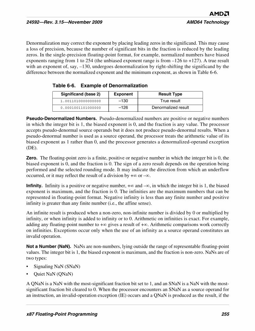
x87 Floating-Point Programming 255
24592—Rev. 3.15—November 2009 AMD64 Technology
Denormalization may correct the exponent by placing leading zeros in the significand. This may causea loss of precision, because the number of significant bits in the fraction is reduced by the leadingzeros. In the single-precision floating-point format, for example, normalized numbers have biasedexponents ranging from 1 to 254 (the unbiased exponent range is from –126 to +127). A true resultwith an exponent of, say, –130, undergoes denormalization by right-shifting the significand by thedifference between the normalized exponent and the minimum exponent, as shown in Table 6-6.
Pseudo-Denormalized Numbers. Pseudo-denormalized numbers are positive or negative numbersin which the integer bit is 1, the biased exponent is 0, and the fraction is any value. The processoraccepts pseudo-denormal source operands but it does not produce pseudo-denormal results. When apseudo-denormal number is used as a source operand, the processor treats the arithmetic value of itsbiased exponent as 1 rather than 0, and the processor generates a denormalized-operand exception(DE).
Zero. The floating-point zero is a finite, positive or negative number in which the integer bit is 0, thebiased exponent is 0, and the fraction is 0. The sign of a zero result depends on the operation beingperformed and the selected rounding mode. It may indicate the direction from which an underflowoccurred, or it may reflect the result of a division by +∞ or –∞.
Infinity. Infinity is a positive or negative number, +∞ and –∞, in which the integer bit is 1, the biasedexponent is maximum, and the fraction is 0. The infinities are the maximum numbers that can berepresented in floating-point format. Negative infinity is less than any finite number and positiveinfinity is greater than any finite number (i.e., the affine sense).
An infinite result is produced when a non-zero, non-infinite number is divided by 0 or multiplied byinfinity, or when infinity is added to infinity or to 0. Arithmetic on infinities is exact. For example,adding any floating-point number to +∞ gives a result of +∞. Arithmetic comparisons work correctlyon infinities. Exceptions occur only when the use of an infinity as a source operand constitutes aninvalid operation.
Not a Number (NaN). NaNs are non-numbers, lying outside the range of representable floating-pointvalues. The integer bit is 1, the biased exponent is maximum, and the fraction is non-zero. NaNs are oftwo types:
• Signaling NaN (SNaN)
• Quiet NaN (QNaN)
A QNaN is a NaN with the most-significant fraction bit set to 1, and an SNaN is a NaN with the most-significant fraction bit cleared to 0. When the processor encounters an SNaN as a source operand foran instruction, an invalid-operation exception (IE) occurs and a QNaN is produced as the result, if the
Table 6-6. Example of Denormalization
Significand (base 2) Exponent Result Type
1.0011010000000000 –130 True result
0.0001001101000000 –126 Denormalized result
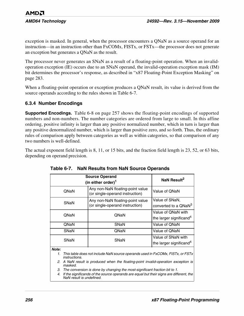
256 x87 Floating-Point Programming
AMD64 Technology 24592—Rev. 3.15—November 2009
exception is masked. In general, when the processor encounters a QNaN as a source operand for aninstruction—in an instruction other than FxCOMx, FISTx, or FSTx—the processor does not generatean exception but generates a QNaN as the result.
The processor never generates an SNaN as a result of a floating-point operation. When an invalid-operation exception (IE) occurs due to an SNaN operand, the invalid-operation exception mask (IM)bit determines the processor’s response, as described in “x87 Floating-Point Exception Masking” onpage 283.
When a floating-point operation or exception produces a QNaN result, its value is derived from thesource operands according to the rules shown in Table 6-7.
6.3.4 Number Encodings
Supported Encodings. Table 6-8 on page 257 shows the floating-point encodings of supportednumbers and non-numbers. The number categories are ordered from large to small. In this affineordering, positive infinity is larger than any positive normalized number, which in turn is larger thanany positive denormalized number, which is larger than positive zero, and so forth. Thus, the ordinaryrules of comparison apply between categories as well as within categories, so that comparison of anytwo numbers is well-defined.
The actual exponent field length is 8, 11, or 15 bits, and the fraction field length is 23, 52, or 63 bits,depending on operand precision.
Table 6-7. NaN Results from NaN Source Operands
Source Operand(in either order)1
NaN Result2
QNaNAny non-NaN floating-point value(or single-operand instruction)
Value of QNaN
SNaNAny non-NaN floating-point value(or single-operand instruction)
Value of SNaN,
converted to a QNaN3
QNaN QNaNValue of QNaN with
the larger significand4
QNaN SNaN Value of QNaN
SNaN QNaN Value of QNaN
SNaN SNaNValue of SNaN with
the larger significand4
Note:1. This table does not include NaN source operands used in FxCOMx, FISTx, or FSTx
instructions.2. A NaN result is produced when the floating-point invalid-operation exception is
masked.3. The conversion is done by changing the most-significant fraction bit to 1.4. If the significands of the source operands are equal but their signs are different, the
NaN result is undefined.
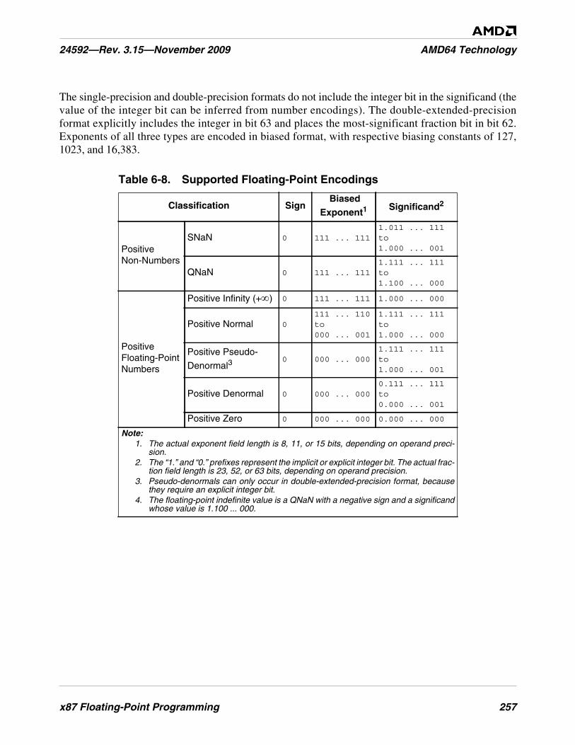
x87 Floating-Point Programming 257
24592—Rev. 3.15—November 2009 AMD64 Technology
The single-precision and double-precision formats do not include the integer bit in the significand (thevalue of the integer bit can be inferred from number encodings). The double-extended-precisionformat explicitly includes the integer in bit 63 and places the most-significant fraction bit in bit 62.Exponents of all three types are encoded in biased format, with respective biasing constants of 127,1023, and 16,383.
Table 6-8. Supported Floating-Point Encodings
Classification SignBiased
Exponent1Significand2
PositiveNon-Numbers
SNaN 0 111 ... 1111.011 ... 111to1.000 ... 001
QNaN 0 111 ... 1111.111 ... 111to1.100 ... 000
PositiveFloating-PointNumbers
Positive Infinity (+∞) 0 111 ... 111 1.000 ... 000
Positive Normal 0111 ... 110to000 ... 001
1.111 ... 111to1.000 ... 000
Positive Pseudo-
Denormal30 000 ... 000
1.111 ... 111to1.000 ... 001
Positive Denormal 0 000 ... 0000.111 ... 111to0.000 ... 001
Positive Zero 0 000 ... 000 0.000 ... 000
Note:1. The actual exponent field length is 8, 11, or 15 bits, depending on operand preci-
sion.2. The “1.” and “0.” prefixes represent the implicit or explicit integer bit. The actual frac-
tion field length is 23, 52, or 63 bits, depending on operand precision.3. Pseudo-denormals can only occur in double-extended-precision format, because
they require an explicit integer bit.4. The floating-point indefinite value is a QNaN with a negative sign and a significand
whose value is 1.100 ... 000.
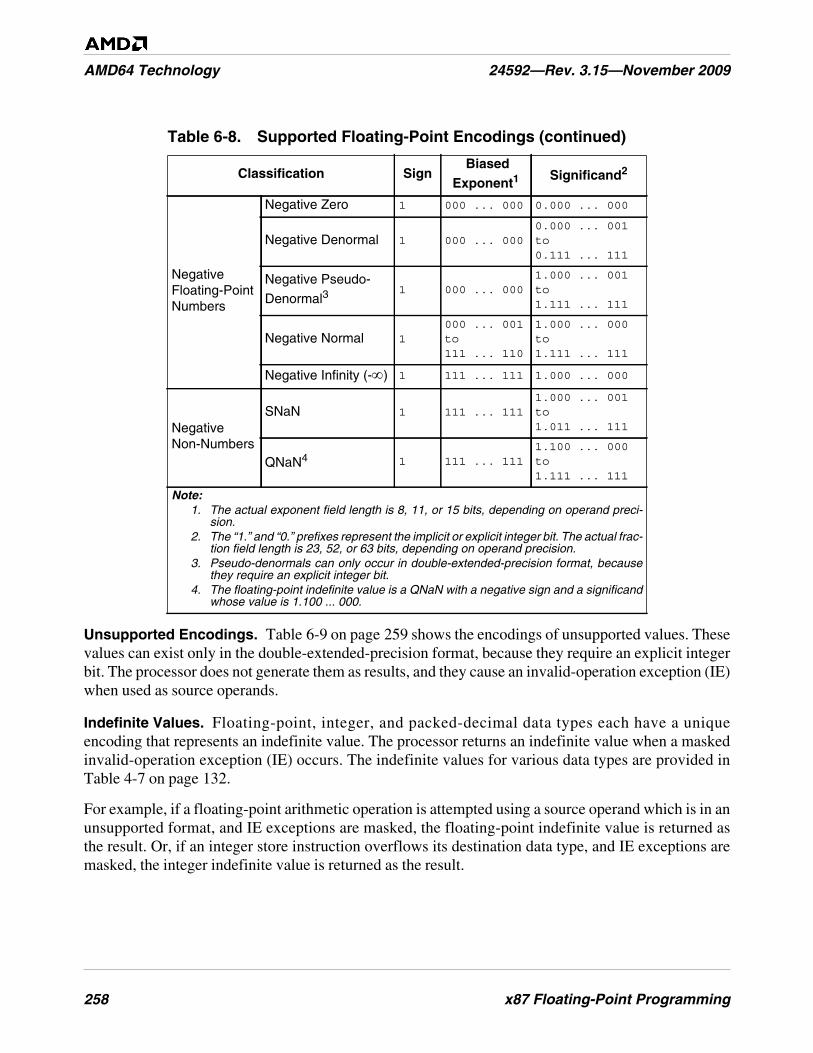
258 x87 Floating-Point Programming
AMD64 Technology 24592—Rev. 3.15—November 2009
Unsupported Encodings. Table 6-9 on page 259 shows the encodings of unsupported values. Thesevalues can exist only in the double-extended-precision format, because they require an explicit integerbit. The processor does not generate them as results, and they cause an invalid-operation exception (IE)when used as source operands.
Indefinite Values. Floating-point, integer, and packed-decimal data types each have a uniqueencoding that represents an indefinite value. The processor returns an indefinite value when a maskedinvalid-operation exception (IE) occurs. The indefinite values for various data types are provided inTable 4-7 on page 132.
For example, if a floating-point arithmetic operation is attempted using a source operand which is in anunsupported format, and IE exceptions are masked, the floating-point indefinite value is returned asthe result. Or, if an integer store instruction overflows its destination data type, and IE exceptions aremasked, the integer indefinite value is returned as the result.
NegativeFloating-PointNumbers
Negative Zero 1 000 ... 000 0.000 ... 000
Negative Denormal 1 000 ... 0000.000 ... 001to0.111 ... 111
Negative Pseudo-
Denormal31 000 ... 000
1.000 ... 001to1.111 ... 111
Negative Normal 1000 ... 001to111 ... 110
1.000 ... 000to1.111 ... 111
Negative Infinity (-∞) 1 111 ... 111 1.000 ... 000
NegativeNon-Numbers
SNaN 1 111 ... 1111.000 ... 001to1.011 ... 111
QNaN4 1 111 ... 1111.100 ... 000to1.111 ... 111
Table 6-8. Supported Floating-Point Encodings (continued)
Classification SignBiased
Exponent1Significand2
Note:1. The actual exponent field length is 8, 11, or 15 bits, depending on operand preci-
sion.2. The “1.” and “0.” prefixes represent the implicit or explicit integer bit. The actual frac-
tion field length is 23, 52, or 63 bits, depending on operand precision.3. Pseudo-denormals can only occur in double-extended-precision format, because
they require an explicit integer bit.4. The floating-point indefinite value is a QNaN with a negative sign and a significand
whose value is 1.100 ... 000.
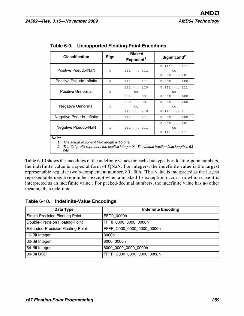
x87 Floating-Point Programming 259
24592—Rev. 3.15—November 2009 AMD64 Technology
Table 6-10 shows the encodings of the indefinite values for each data type. For floating-point numbers,the indefinite value is a special form of QNaN. For integers, the indefinite value is the largestrepresentable negative two’s-complement number, 80...00h. (This value is interpreted as the largestrepresentable negative number, except when a masked IE exception occurs, in which case it isinterpreted as an indefinite value.) For packed-decimal numbers, the indefinite value has no othermeaning than indefinite.
Table 6-9. Unsupported Floating-Point Encodings
Classification SignBiased
Exponent1Significand2
Positive Pseudo-NaN 0 111 ... 1110.111 ... 111
to0.000 ... 001
Positive Pseudo-Infinity 0 111 ... 111 0.000 ... 000
Positive Unnormal 0111 ... 110
to000 ... 001
0.111 ... 111to
0.000 ... 000
Negative Unnormal 1000 ... 001
to111 ... 110
0.000 ... 000to
0.111 ... 111
Negative Pseudo-Infinity 1 111 ... 111 0.000 ... 000
Negative Pseudo-NaN 1 111 ... 1110.000 ... 001
to0.111 ... 111
Note:1. The actual exponent field length is 15 bits.2. The “0.” prefix represent the explicit integer bit. The actual fraction field length is 63
bits.
Table 6-10. Indefinite-Value Encodings
Data Type Indefinite Encoding
Single-Precision Floating-Point FFC0_0000h
Double-Precision Floating-Point FFF8_0000_0000_0000h
Extended-Precision Floating-Point FFFF_C000_0000_0000_0000h
16-Bit Integer 8000h
32-Bit Integer 8000_0000h
64-Bit Integer 8000_0000_0000_0000h
80-Bit BCD FFFF_C000_0000_0000_0000h
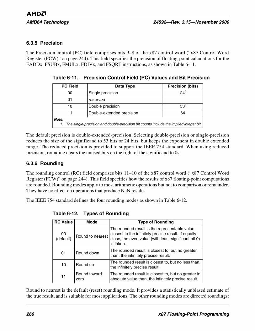
260 x87 Floating-Point Programming
AMD64 Technology 24592—Rev. 3.15—November 2009
6.3.5 Precision
The Precision control (PC) field comprises bits 9–8 of the x87 control word (“x87 Control WordRegister (FCW)” on page 244). This field specifies the precision of floating-point calculations for theFADDx, FSUBx, FMULx, FDIVx, and FSQRT instructions, as shown in Table 6-11.
The default precision is double-extended-precision. Selecting double-precision or single-precisionreduces the size of the significand to 53 bits or 24 bits, but keeps the exponent in double extendedrange. The reduced precision is provided to support the IEEE 754 standard. When using reducedprecision, rounding clears the unused bits on the right of the significand to 0s.
6.3.6 Rounding
The rounding control (RC) field comprises bits 11–10 of the x87 control word (“x87 Control WordRegister (FCW)” on page 244). This field specifies how the results of x87 floating-point computationsare rounded. Rounding modes apply to most arithmetic operations but not to comparison or remainder.They have no effect on operations that produce NaN results.
The IEEE 754 standard defines the four rounding modes as shown in Table 6-12.
Round to nearest is the default (reset) rounding mode. It provides a statistically unbiased estimate ofthe true result, and is suitable for most applications. The other rounding modes are directed roundings:
Table 6-11. Precision Control Field (PC) Values and Bit Precision
PC Field Data Type Precision (bits)
00 Single precision 241
01 reserved
10 Double precision 531
11 Double-extended precision 64
Note:1. The single-precision and double-precision bit counts include the implied integer bit.
Table 6-12. Types of Rounding
RC Value Mode Type of Rounding
00(default)
Round to nearest
The rounded result is the representable valueclosest to the infinitely precise result. If equallyclose, the even value (with least-significant bit 0)is taken.
01 Round downThe rounded result is closest to, but no greaterthan, the infinitely precise result.
10 Round upThe rounded result is closest to, but no less than,the infinitely precise result.
11Round towardzero
The rounded result is closest to, but no greater inabsolute value than, the infinitely precise result.
x87 Floating-Point Programming 261
24592—Rev. 3.15—November 2009 AMD64 Technology
round up (toward +∞), round down (toward –∞), and round toward zero. Round up and round down areused in interval arithmetic, in which upper and lower bounds bracket the true result of a computation.Round toward zero takes the smaller in magnitude, that is, always truncates.
The processor produces a floating-point result defined by the IEEE standard to be infinitely precise.This result may not be representable exactly in the destination format, because only a subset of thecontinuum of real numbers finds exact representation in any particular floating-point format.Rounding modifies such a result to conform to the destination format, thereby making the resultinexact and also generating a precision exception (PE), as described in “x87 Floating-Point ExceptionCauses” on page 279.
Suppose, for example, the following 24-bit result is to be represented in single-precision format, where“E2 1010” represents the biased exponent:
1.0011 0101 0000 0001 0010 0111 E2 1010
This result has no exact representation, because the least-significant 1 does not fit into the single-precision format, which allows for only 23 bits of fraction. The rounding control field determines thedirection of rounding. Rounding introduces an error in a result that is less than one unit in the last place(ulp), that is, the least-significant bit position of the floating-point representation.
6.4 Instruction Summary
This section summarizes the functions of the x87 floating-point instructions. The instructions areorganized here by functional group—such as data-transfer, arithmetic, and so on. More detail onindividual instructions is given in the alphabetically organized “x87 Floating-Point InstructionReference” in Volume 5.
Software running at any privilege level can use any of these instructions, if the CPUID instructionreports support for the instructions (see “Feature Detection” on page 278). Most x87 instructions takefloating-point data types for both their source and destination operands, although some x87 data-conversion instructions take integer formats for their source or destination operands.
6.4.1 Syntax
Each instruction has a mnemonic syntax used by assemblers to specify the operation and the operandsto be used for source and destination (result) data. Many of x87 instructions have the following syntax:
MNEMONIC st(j), st(i)
Figure 6-10 on page 262 shows an example of the mnemonic syntax for a floating-point add (FADD)instruction.
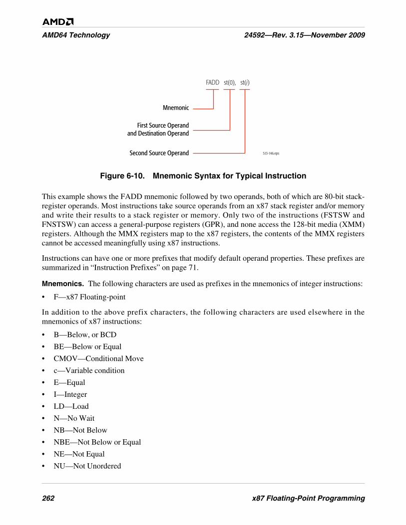
262 x87 Floating-Point Programming
AMD64 Technology 24592—Rev. 3.15—November 2009
Figure 6-10. Mnemonic Syntax for Typical Instruction
This example shows the FADD mnemonic followed by two operands, both of which are 80-bit stack-register operands. Most instructions take source operands from an x87 stack register and/or memoryand write their results to a stack register or memory. Only two of the instructions (FSTSW andFNSTSW) can access a general-purpose registers (GPR), and none access the 128-bit media (XMM)registers. Although the MMX registers map to the x87 registers, the contents of the MMX registerscannot be accessed meaningfully using x87 instructions.
Instructions can have one or more prefixes that modify default operand properties. These prefixes aresummarized in “Instruction Prefixes” on page 71.
Mnemonics. The following characters are used as prefixes in the mnemonics of integer instructions:
• F—x87 Floating-point
In addition to the above prefix characters, the following characters are used elsewhere in themnemonics of x87 instructions:
• B—Below, or BCD
• BE—Below or Equal
• CMOV—Conditional Move
• c—Variable condition
• E—Equal
• I—Integer
• LD—Load
• N—No Wait
• NB—Not Below
• NBE—Not Below or Equal
• NE—Not Equal
• NU—Not Unordered
513-146.eps
Mnemonic
First Source Operandand Destination Operand
Second Source Operand
FADD st(0), st(i)
x87 Floating-Point Programming 263
24592—Rev. 3.15—November 2009 AMD64 Technology
• P—Pop
• PP—Pop Twice
• R—Reverse
• ST—Store
• U—Unordered
• x—One or more variable characters in the mnemonic
For example, the mnemonic for the store instruction that stores the top-of-stack and pops the stack isFSTP. In this mnemonic, the F means a floating-point instruction, the ST means a store, and the Pmeans pop the stack.
6.4.2 Data Transfer and Conversion
The data transfer and conversion instructions copy data—in some cases with data conversion—between x87 stack registers and memory or between stack positions.
Load or Store Floating-Point
• FLD—Floating-Point Load
• FST—Floating-Point Store Stack Top
• FSTP—Floating-Point Store Stack Top and Pop
The FLD instruction pushes the source operand onto the top-of-stack, ST(0). The source operand maybe a single-precision, double-precision, or double-extended-precision floating-point value in memoryor the contents of a specified stack position, ST(i).
The FST instruction copies the value at the top-of-stack, ST(0), to a specified stack position, ST(i), orto a 32-bit or 64-bit memory location. If the destination is a memory location, the value copied isconverted to the precision allowed by the destination and rounded, as specified by the rounding control(RC) field of the x87 control word. If the top-of-stack value is a NaN or an infinity, FST truncates thestack-top exponent and significand to fit the destination size. (For details, see “FST FSTP” in AMD64Architecture Programmer’s Manual Volume 5: 64-bit Media and x87 Floating-Point Instructions,order# 26569.
The FSTP instruction is similar to FST, except that FSTP can also store to an 80-bit memory locationand it pops the stack after the store. FSTP can be used to clean up the x87 stack at the end of an x87procedure by removing one register of preloaded data from the stack.
Convert and Load or Store Integer
• FILD—Floating-Point Load Integer
• FIST—Floating-Point Integer Store
• FISTP—Floating-Point Integer Store and Pop
• FISTTP—Floating-Point Integer Truncate and Store
264 x87 Floating-Point Programming
AMD64 Technology 24592—Rev. 3.15—November 2009
The FILD instruction converts the 16-bit, 32-bit, or 64-bit source signed integer in memory into adouble-extended-precision floating-point value and pushes the result onto the top-of-stack, ST(0).
The FIST instruction converts and rounds the source value in the top-of-stack, ST(0), to a signedinteger and copies it to the specified 16-bit or 32-bit memory location. The type of rounding isdetermined by the rounding control (RC) field of the x87 control word.
The FISTP instruction is similar to FIST, except that FISTP can also store the result to a 64-bitmemory location and it pops ST(0) after the store.
The FISTTP instruction converts a floating-point value in ST(0) to an integer by truncating thefractional part of the number and storing the integer result to the memory address specified by thedestination operand. FISTTP then pops the floating point register stack. The FISTTP instructionignores the rounding mode specified by the x87 control word.
Convert and Load or Store BCD
• FBLD—Floating-Point Load Binary-Coded Decimal
• FBSTP—Floating-Point Store Binary-Coded Decimal Integer and Pop
The FBLD and FBSTP instructions, respectively, push and pop an 80-bit packed BCD memory valueon and off the top-of-stack, ST(0). FBLD first converts the value being pushed to a double-extended-precision floating-point value. FBSTP rounds the value being popped to an integer, using the roundingmode specified by the RC field, and converts the value to an 80-bit packed BCD value. Thus, noFRNDIT (round-to-integer) instruction is needed prior to FBSTP.
Conditional Move
• FCMOVB—Floating-Point Conditional Move If Below
• FCMOVBE—Floating-Point Conditional Move If Below or Equal
• FCMOVE—Floating-Point Conditional Move If Equal
• FCMOVNB—Floating-Point Conditional Move If Not Below
• FCMOVNBE—Floating-Point Conditional Move If Not Below or Equal
• FCMOVNE—Floating-Point Conditional Move If Not Equal
• FCMOVNU—Floating-Point Conditional Move If Not Unordered
• FCMOVU—Floating-Point Conditional Move If Unordered
The FCMOVcc instructions copy the contents of a specified stack position, ST(i), to the top-of-stack,ST(0), if the specified rFLAGS condition is met. Table 6-13 on page 265 specifies the flagcombinations for each conditional move.
x87 Floating-Point Programming 265
24592—Rev. 3.15—November 2009 AMD64 Technology
Exchange
• FXCH—Floating-Point Exchange
The FXCH instruction exchanges the contents of a specified stack position, ST(i), with the top-of-stack, ST(0). The top-of-stack pointer is left unchanged. In the form of the instruction that specifies nooperand, the contents of ST(1) and ST(0) are exchanged.
Extract
• FXTRACT—Floating-Point Extract Exponent and Significand
The FXTRACT instruction copies the unbiased exponent of the original value in the top-of-stack,ST(0), and writes it as a floating-point value to ST(1), then copies the significand and sign of theoriginal value in the top-of-stack and writes it as a floating-point value with an exponent of zero to thetop-of-stack, ST(0).
6.4.3 Load Constants
Load 0, 1, or Pi
• FLDZ—Floating-Point Load +0.0
• FLD1—Floating-Point Load +1.0
• FLDPI—Floating-Point Load Pi
The FLDZ, FLD1, and FLDPI instructions, respectively, push the floating-point constant value, +0.0,+1.0, and Pi (3.141592653...), onto the top-of-stack, ST(0).
Load Logarithm
• FLDL2E—Floating-Point Load Log2 e
• FLDL2T—Floating-Point Load Log2 10
Table 6-13. rFLAGS Conditions for FCMOVcc
Condition Mnemonic rFLAGS Register State
Below B Carry flag is set (CF = 1)
Below or Equal BEEither carry flag or zero flag is set
(CF = 1 or ZF = 1)
Equal E Zero flag is set (ZF = 1)
Not Below NB Carry flag is not set (CF = 0)
Not Below or Equal NBENeither carry flag nor zero flag is set
(CF = 0, ZF = 0)
Not Equal NE Zero flag is not set (ZF = 0)
Not Unordered NU Parity flag is not set (PF = 0)
Unordered U Parity flag is set (PF = 1)
266 x87 Floating-Point Programming
AMD64 Technology 24592—Rev. 3.15—November 2009
• FLDLG2—Floating-Point Load Log10 2
• FLDLN2—Floating-Point Load Ln 2
The FLDL2E, FLDL2T, FLDLG2, and FLDLN2 instructions, respectively, push the floating-pointconstant value, log2e, log210, log102, and loge2, onto the top-of-stack, ST(0).
6.4.4 Arithmetic
The arithmetic instructions support addition, subtraction, multiplication, division, change-sign, round,round to integer, partial remainder, and square root. In most arithmetic operations, one of the sourceoperands is the top-of-stack, ST(0). The other source operand can be another stack entry, ST(i), or afloating-point or integer operand in memory.
The non-commutative operations of subtraction and division have two forms, the direct FSUB andFDIV, and the reverse FSUBR and FDIVR. FSUB, for example, subtracts the right operand from theleft operand, and writes the result to the left operand. FSUBR subtracts the left operand from the rightoperand, and writes the result to the left operand. The FADD and FMUL operations have no reversecounterparts.
Addition
• FADD—Floating-Point Add
• FADDP—Floating-Point Add and Pop
• FIADD—Floating-Point Add Integer to Stack Top
The FADD instruction syntax has forms that include one or two explicit source operands. In the one-operand form, the instruction reads a 32-bit or 64-bit floating-point value from memory, converts it tothe double-extended-precision format, adds it to ST(0), and writes the result to ST(0). In the two-operand form, the instruction adds both source operands from stack registers and writes the result tothe first operand.
The FADDP instruction syntax has forms that include zero or two explicit source operands. In thezero-operand form, the instruction adds ST(0) to ST(1), writes the result to ST(1), and pops the stack.In the two-operand form, the instruction adds both source operands from stack registers, writes theresult to the first operand, and pops the stack.
The FIADD instruction reads a 16-bit or 32-bit integer value from memory, converts it to the double-extended-precision format, adds it to ST(0), and writes the result to ST(0).
Subtraction
• FSUB—Floating-Point Subtract
• FSUBP—Floating-Point Subtract and Pop
• FISUB—Floating-Point Integer Subtract
• FSUBR—Floating-Point Subtract Reverse
• FSUBRP—Floating-Point Subtract Reverse and Pop
x87 Floating-Point Programming 267
24592—Rev. 3.15—November 2009 AMD64 Technology
• FISUBR—Floating-Point Integer Subtract Reverse
The FSUB instruction syntax has forms that include one or two explicit source operands. In the one-operand form, the instruction reads a 32-bit or 64-bit floating-point value from memory, converts it tothe double-extended-precision format, subtracts it from ST(0), and writes the result to ST(0). In thetwo-operand form, both source operands are located in stack registers. The instruction subtracts thesecond operand from the first operand and writes the result to the first operand.
The FSUBP instruction syntax has forms that include zero or two explicit source operands. In the zero-operand form, the instruction subtracts ST(0) from ST(1), writes the result to ST(1), and pops thestack. In the two-operand form, both source operands are located in stack registers. The instructionsubtracts the second operand from the first operand, writes the result to the first operand, and pops thestack.
The FISUB instruction reads a 16-bit or 32-bit integer value from memory, converts it to the double-extended-precision format, subtracts it from ST(0), and writes the result to ST(0).
The FSUBR and FSUBRP instructions perform the same operations as FSUB and FSUBP,respectively, except that the source operands are reversed. Instead of subtracting the second operandfrom the first operand, FSUBR and FSUBRP subtract the first operand from the second operand.
Multiplication
• FMUL—Floating-Point Multiply
• FMULP—Floating-Point Multiply and Pop
• FIMUL—Floating-Point Integer Multiply
The FMUL instruction has three forms. One form of the instruction multiplies two double-extendedprecision floating-point values located in ST(0) and another floating-point stack register and leaves theproduct in ST(0). The second form multiplies two double-extended precision floating-point valueslocated in ST(0) and another floating-point stack destination register and leaves the product in thedestination register. The third form converts a floating-point value in a specified memory location todouble-extended-precision format, multiplies the result by the value in ST(0) and writes the product toST(0).
The FMULP instruction syntax is similar to the form of FMUL described in the previous paragraph.This instruction pops the floating-point register stack after performing the multiplication operation.This instruction cannot take a memory operand.
The FIMUL instruction reads a 16-bit or 32-bit integer value from memory, converts it to the double-extended-precision format, multiplies ST(0) by the memory operand, and writes the result to ST(0).
Division
• FDIV—Floating-Point Divide
• FDIVP—Floating-Point Divide and Pop
• FIDIV—Floating-Point Integer Divide

268 x87 Floating-Point Programming
AMD64 Technology 24592—Rev. 3.15—November 2009
• FDIVR—Floating-Point Divide Reverse
• FDIVRP—Floating-Point Divide Reverse and Pop
• FIDIVR—Floating-Point Integer Divide Reverse
The FDIV instruction syntax has forms that include one or two source explicit operands that may besingle-precision or double-precision floating-point values or 16-bit or 32-bit integer values. In the one-operand form, the instruction reads a value from memory, divides ST(0) by the memory operand, andwrites the result to ST(0). In the two-operand form, both source operands are located in stack registers.The instruction divides the first operand by the second operand and writes the result to the firstoperand.
The FDIVP instruction syntax has forms that include zero or two explicit source operands. In the zero-operand form, the instruction divides ST(1) by ST(0), writes the result to ST(1), and pops the stack. Inthe two-operand form, both source operands are located in stack registers. The instruction divides thefirst operand by the second operand, writes the result to the first operand, and pops the stack.
The FIDIV instruction reads a 16-bit or 32-bit integer value from memory, converts it to the double-extended-precision format, divides ST(0) by the memory operand, and writes the result to ST(0).
The FDIVR and FDIVRP instructions perform the same operations as FDIV and FDIVP, respectively,except that the source operands are reversed. Instead of dividing the first operand by the secondoperand, FDIVR and FDIVRP divide the second operand by the first operand.
Change Sign
• FABS—Floating-Point Absolute Value
• FCHS—Floating-Point Change Sign
The FABS instruction changes the top-of-stack value, ST(0), to its absolute value by clearing its signbit to 0. The top-of-stack value is always positive following execution of the FABS instruction. TheFCHS instruction complements the sign bit of ST(0). For example, if ST(0) was +0.0 before theexecution of FCHS, it is changed to -0.0.
Round
• FRNDINT—Floating-Point Round to Integer
The FRNDINT instruction rounds the top-of-stack value, ST(0), to an integer value, although the valueremains in double-extended-precision floating-point format. Rounding takes place according to thesetting of the rounding control (RC) field in the x87 control word.
Partial Remainder
• FPREM—Floating-Point Partial Remainder
• FPREM1—Floating-Point Partial Remainder
The FPREM instruction returns the remainder obtained by dividing ST(0) by ST(1) and stores it inST(0). If the exponent difference between ST(0) and ST(1) is less than 64, all integer bits of the
x87 Floating-Point Programming 269
24592—Rev. 3.15—November 2009 AMD64 Technology
quotient are calculated, guaranteeing that the remainder returned is less in magnitude than the divisorin ST(1). If the exponent difference is equal to or greater than 64, only a subset of the integer quotientbits, numbering between 32 and 63, are calculated and a partial remainder is returned. FPREM can berepeated on a partial remainder until reduction is complete. It can be used to bring the operands oftranscendental functions into their proper range. FPREM is supported for software written for earlyx87 coprocessors. Unlike the FPREM1 instruction, FPREM does not calculate the partial remainder asspecified in IEEE Standard 754.
The FPREM1 instruction works like FPREM, except that the FPREM1 quotient is rounded usinground-to-nearest mode, whereas FPREM truncates the quotient.
Square Root
• FSQRT—Floating-Point Square Root
The FSQRT instruction replaces the contents of the top-of-stack, ST(0), with its square root.
6.4.5 Transcendental Functions
The transcendental instructions compute trigonometric functions, inverse trigonometric functions,logarithmic functions, and exponential functions.
Trigonometric Functions
• FSIN—Floating-Point Sine
• FCOS—Floating-Point Cosine
• FSINCOS—Floating-Point Sine and Cosine
• FPTAN—Floating-Point Partial Tangent
• FPATAN—Floating-Point Partial Arctangent
The FSIN instruction replaces the contents of ST(0) (in radians) with its sine.
The FCOS instruction replaces the contents of ST(0) (in radians) with its cosine.
The FSINCOS instruction computes both the sine and cosine of the contents of ST(0) (in radians) andwrites the sine to ST(0) and pushes the cosine onto the stack. Frequently, a piece of code that needs tocompute the sine of an argument also needs to compute the cosine of that same argument. In suchcases, use the FSINCOS instruction to compute both functions concurrently, which is faster than usingseparate FSIN and FCOS instructions.
The FPTAN instruction replaces the contents of the ST(0) (in radians), with its tangent, in radians, andpushes the value 1.0 onto the stack.
The FPATAN instruction computes θ = arctan (Y/X), in which X is located in ST(0) and Y in ST(1).The result, θ, is written over Y in ST(1), and the stack is popped.
FSIN, FCOS, FSINCOS, and FPTAN are architecturally restricted in their argument range. Onlyarguments with a magnitude of less than 263 can be evaluated. If the argument is out of range, the C2
270 x87 Floating-Point Programming
AMD64 Technology 24592—Rev. 3.15—November 2009
condition-code bit in the x87 status word is set to 1, and the argument is returned as the result. Ifsoftware detects an out-of-range argument, the FPREM or FPREM1 instruction can be used to reducethe magnitude of the argument before using the FSIN, FCOS, FSINCOS, or FPTAN instruction again.
Logarithmic Functions
• F2XM1—Floating-Point Compute 2x–1
• FSCALE—Floating-Point Scale
• FYL2X—Floating-Point y * log2x
• FYL2XP1—Floating-Point y * log2(x +1)
The F2XM1 instruction computes Y = 2X – 1. X is located in ST(0) and must fall between –1 and +1.Y replaces X in ST(0). If ST(0) is out of range, the instruction returns an undefined result but no x87status-word exception bits are affected.
The FSCALE instruction replaces ST(0) with ST(0) times 2n, where n is the value in ST(1) truncatedto an integer. This provides a fast method of multiplying by integral powers of 2.
The FYL2X instruction computes Z = Y * log2 X. X is located in ST(0) and Y is located in ST(1). Xmust be greater than 0. The result, Z, replaces Y in ST(1), which becomes the new top-of-stackbecause X is popped off the stack.
The FYL2XP1 instruction computes Z = Y * log2(X + 1). X located in ST(0) and must be in the range0 < |X| < (1 – 2½ / 2). Y is taken from ST(1). The result, Z, replaces Y in ST(1), which becomes the newtop-of-stack because X is popped off the stack.
Accuracy of Transcendental Results. x87 computations are carried out in double-extended-precision format, so that the transcendental functions provide results accurate to within one unit in thelast place (ulp) for each of the floating-point data types.
Argument Reduction Using Pi. The FPREM and FPREM1 instructions can be used to reduce anargument of a trigonometric function by a multiple of Pi. The following example shows a reduction by2π:
sin(n*2π + x) = sin(x) for all integral n
In this example, the range is 0 ≤ x < 2π in the case of FPREM or -π ≤ x ≤ π in the case of FPREM1.Negative arguments are reduced by repeatedly subtracting –2π. See “Partial Remainder” on page 268for details of the instructions.
6.4.6 Compare and Test
The compare-and-test instructions set and clear flags in the rFLAGS register to indicate therelationship between two operands (less, equal, greater, or unordered).
Floating-Point Ordered Compare
• FCOM—Floating-Point Compare
x87 Floating-Point Programming 271
24592—Rev. 3.15—November 2009 AMD64 Technology
• FCOMP—Floating-Point Compare and Pop
• FCOMPP—Floating-Point Compare and Pop Twice
• FCOMI—Floating-Point Compare and Set Flags
• FCOMIP—Floating-Point Compare and Set Flags and Pop
The FCOM instruction syntax has forms that include zero or one explicit source operands. In the zero-operand form, the instruction compares ST(1) with ST(0) and writes the x87 status-word conditioncodes accordingly. In the one-operand form, the instruction reads a 32-bit or 64-bit value frommemory, compares it with ST(0), and writes the x87 condition codes accordingly.
The FCOMP instruction performs the same operation as FCOM but also pops ST(0) after writing thecondition codes.
The FCOMPP instruction performs the same operation as FCOM but also pops both ST(0) and ST(1).FCOMPP can be used to initialize the x87 stack at the end of an x87 procedure by removing tworegisters of preloaded data from the stack.
The FCOMI instruction compares the contents of ST(0) with the contents of another stack register andwrites the ZF, PF, and CF flags in the rFLAGS register as shown in Table 6-14. If no source isspecified, ST(0) is compared to ST(1). If ST(0) or the source operand is a NaN or in an unsupportedformat, the flags are set to indicate an unordered condition.
The FCOMIP instruction performs the same comparison as FCOMI but also pops ST(0) after writingthe rFLAGS bits.
For comparison-based branches, the combination of FCOMI and FCMOVcc is faster than the classicalmethod of using FxSTSW AX to copy condition codes through the AX register to the rFLAGS register,where they can provide branch direction for conditional operations.
The FCOMx instructions perform ordered compares, as opposed to the FUCOMx instructions. See thedescription of ordered vs. unordered compares immediately below.
Floating-Point Unordered Compare
• FUCOM—Floating-Point Unordered Compare
• FUCOMP—Floating-Point Unordered Compare and Pop
• FUCOMPP—Floating-Point Unordered Compare and Pop Twice
• FUCOMI—Floating-Point Unordered Compare and Set Flags
Table 6-14. rFLAGS Values for FCOMI Instruction
Flag ST(0) > ST(i) ST(0) < ST(i) ST(0) = ST(i) Unordered
ZF 0 0 1 1
PF 0 0 0 1
CF 0 1 0 1
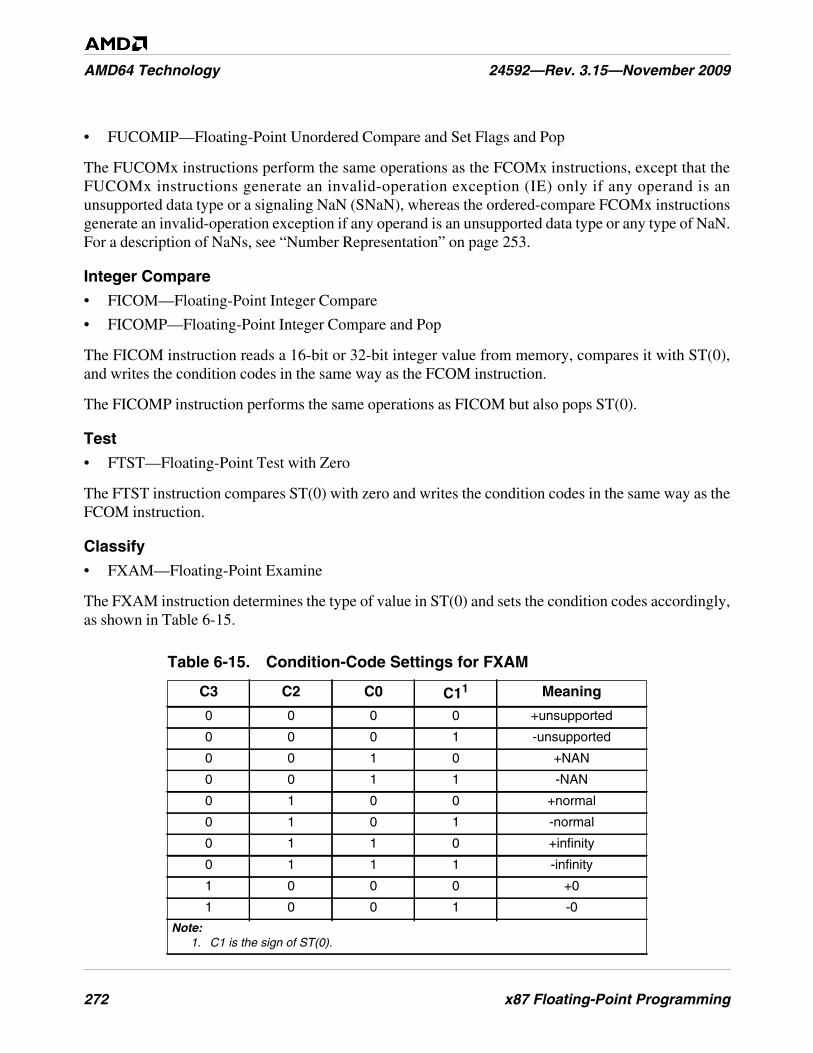
272 x87 Floating-Point Programming
AMD64 Technology 24592—Rev. 3.15—November 2009
• FUCOMIP—Floating-Point Unordered Compare and Set Flags and Pop
The FUCOMx instructions perform the same operations as the FCOMx instructions, except that theFUCOMx instructions generate an invalid-operation exception (IE) only if any operand is anunsupported data type or a signaling NaN (SNaN), whereas the ordered-compare FCOMx instructionsgenerate an invalid-operation exception if any operand is an unsupported data type or any type of NaN.For a description of NaNs, see “Number Representation” on page 253.
Integer Compare
• FICOM—Floating-Point Integer Compare
• FICOMP—Floating-Point Integer Compare and Pop
The FICOM instruction reads a 16-bit or 32-bit integer value from memory, compares it with ST(0),and writes the condition codes in the same way as the FCOM instruction.
The FICOMP instruction performs the same operations as FICOM but also pops ST(0).
Test
• FTST—Floating-Point Test with Zero
The FTST instruction compares ST(0) with zero and writes the condition codes in the same way as theFCOM instruction.
Classify
• FXAM—Floating-Point Examine
The FXAM instruction determines the type of value in ST(0) and sets the condition codes accordingly,as shown in Table 6-15.
Table 6-15. Condition-Code Settings for FXAM
C3 C2 C0 C11 Meaning
0 0 0 0 +unsupported
0 0 0 1 -unsupported
0 0 1 0 +NAN
0 0 1 1 -NAN
0 1 0 0 +normal
0 1 0 1 -normal
0 1 1 0 +infinity
0 1 1 1 -infinity
1 0 0 0 +0
1 0 0 1 -0
Note:1. C1 is the sign of ST(0).
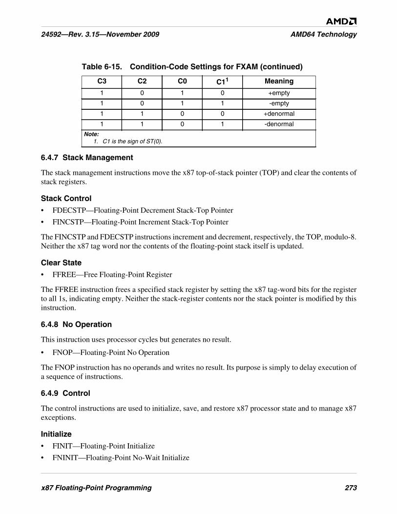
x87 Floating-Point Programming 273
24592—Rev. 3.15—November 2009 AMD64 Technology
6.4.7 Stack Management
The stack management instructions move the x87 top-of-stack pointer (TOP) and clear the contents ofstack registers.
Stack Control
• FDECSTP—Floating-Point Decrement Stack-Top Pointer
• FINCSTP—Floating-Point Increment Stack-Top Pointer
The FINCSTP and FDECSTP instructions increment and decrement, respectively, the TOP, modulo-8.Neither the x87 tag word nor the contents of the floating-point stack itself is updated.
Clear State
• FFREE—Free Floating-Point Register
The FFREE instruction frees a specified stack register by setting the x87 tag-word bits for the registerto all 1s, indicating empty. Neither the stack-register contents nor the stack pointer is modified by thisinstruction.
6.4.8 No Operation
This instruction uses processor cycles but generates no result.
• FNOP—Floating-Point No Operation
The FNOP instruction has no operands and writes no result. Its purpose is simply to delay execution ofa sequence of instructions.
6.4.9 Control
The control instructions are used to initialize, save, and restore x87 processor state and to manage x87exceptions.
Initialize
• FINIT—Floating-Point Initialize
• FNINIT—Floating-Point No-Wait Initialize
1 0 1 0 +empty
1 0 1 1 -empty
1 1 0 0 +denormal
1 1 0 1 -denormal
Table 6-15. Condition-Code Settings for FXAM (continued)
C3 C2 C0 C11 Meaning
Note:1. C1 is the sign of ST(0).
274 x87 Floating-Point Programming
AMD64 Technology 24592—Rev. 3.15—November 2009
The FINIT and FNINIT instructions set all bits in the x87 control-word, status-word, and tag wordregisters to their default values. Assemblers issue FINIT as an FWAIT instruction followed by anFNINIT instruction. Thus, FINIT (but not FNINIT) reports pending unmasked x87 floating-pointexceptions before performing the initialization.
Both FINIT and FNINIT write the control word with its initialization value, 037Fh, which specifiesround-to-nearest, all exceptions masked, and double-extended-precision. The tag word indicates thatthe floating-point registers are empty. The status word and the four condition-code bits are cleared to 0.The x87 pointers and opcode state (“Pointers and Opcode State” on page 247) are all cleared to 0.
The FINIT instruction should be used when pending x87 floating-point exceptions are being reported(unmasked). The no-wait instruction, FNINIT, should be used when pending x87 floating-pointexceptions are not being reported (masked).
Wait for Exceptions
• FWAIT or WAIT—Wait for Unmasked x87 Floating-Point Exceptions
The FWAIT and WAIT instructions are synonyms. The instruction forces the processor to test for andhandle any pending, unmasked x87 floating-point exceptions.
Clear Exceptions
• FCLEX—Floating-Point Clear Flags
• FNCLEX—Floating-Point No-Wait Clear Flags
These instructions clear the status-word exception flags, stack-fault flag, and busy flag. They leave thefour condition-code bits undefined.
Assemblers issue FCLEX as an FWAIT instruction followed by an FNCLEX instruction. Thus,FCLEX (but not FNCLEX) reports pending unmasked x87 floating-point exceptions before clearingthe exception flags.
The FCLEX instruction should be used when pending x87 floating-point exceptions are being reported(unmasked). The no-wait instruction, FNCLEX, should be used when pending x87 floating-pointexceptions are not being reported (masked).
Save and Restore x87 Control Word
• FLDCW—Floating-Point Load x87 Control Word
• FSTCW—Floating-Point Store Control Word
• FNSTCW—Floating-Point No-Wait Store Control Word
These instructions load or store the x87 control-word register as a 2-byte value from or to a memorylocation.
The FLDCW instruction loads a control word. If the loaded control word unmasks any pending x87floating-point exceptions, these exceptions are reported when the next non-control x87 or 64-bit mediainstruction is executed.

x87 Floating-Point Programming 275
24592—Rev. 3.15—November 2009 AMD64 Technology
Assemblers issue FSTCW as an FWAIT instruction followed by an FNSTCW instruction. Thus,FSTCW (but not FNSTCW) reports pending unmasked x87 floating-point exceptions before storingthe control word.
The FSTCW instruction should be used when pending x87 floating-point exceptions are beingreported (unmasked). The no-wait instruction, FNSTCW, should be used when pending x87 floating-point exceptions are not being reported (masked).
Save x87 Status Word
• FSTSW—Floating-Point Store Status Word
• FNSTSW—Floating-Point No-Wait Store Status Word
These instructions store the x87 status word either at a specified 2-byte memory location or in the AXregister. The second form, FxSTSW AX, is used in older code to copy condition codes through the AXregister to the rFLAGS register, where they can be used for conditional branching using general-purpose instructions. However, the combination of FCOMI and FCMOVcc provides a faster method ofconditional branching.
Assemblers issue FSTSW as an FWAIT instruction followed by an FNSTSW instruction. Thus,FSTSW (but not FNSTSW) reports pending unmasked x87 floating-point exceptions before storingthe status word.
The FSTSW instruction should be used when pending x87 floating-point exceptions are beingreported (unmasked). The no-wait instruction, FNSTSW, should be used when pending x87 floating-point exceptions are not being reported (masked).
Save and Restore x87 Environment
• FLDENV—Floating-Point Load x87 Environment
• FNSTENV—Floating-Point No-Wait Store Environment
• FSTENV—Floating-Point Store Environment
These instructions load or store the entire x87 environment (non-data processor state) as a 14-byte or28-byte block, depending on effective operand size, from or to memory.
When executing FLDENV, any exception flags are set in the new status word, and these exceptions areunmasked in the control word, a floating-point exception occurs when the next non-control x87 or 64-bit media instruction is executed.
Assemblers issue FSTENV as an FWAIT instruction followed by an FNSTENV instruction. Thus,FSTENV (but not FNSTENV) reports pending unmasked x87 floating-point exceptions before storingthe status word.
The x87 environment includes the x87 control word register, x87 status word register, x87 tag word,last x87 instruction pointer, last x87 data pointer, and last x87 opcode. See “Media and x87 ProcessorState” in Volume 2 for details on how the x87 environment is stored in memory.
276 x87 Floating-Point Programming
AMD64 Technology 24592—Rev. 3.15—November 2009
Save and Restore x87 and 64-Bit Media State
• FSAVE—Save x87 and MMX State.
• FNSAVE—Save No-Wait x87 and MMX State.
• FRSTOR—Restore x87 and MMX State.
These instructions save and restore the entire processor state for x87 floating-point instructions and64-bit media instructions. The instructions save and restore either 94 or 108 bytes of data, dependingon the effective operand size.
Assemblers issue FSAVE as an FWAIT instruction followed by an FNSAVE instruction. Thus, FSAVE(but not FNSAVE) reports pending unmasked x87 floating-point exceptions before saving the state.
After saving the state, the processor initializes the x87 state by performing the equivalent of an FINITinstruction. For details, see “State-Saving” on page 290.
Save and Restore x87, 128-Bit, and 64-Bit State
• FXSAVE—Save XMM, MMX, and x87 State.
• FXRSTOR—Restore XMM, MMX, and x87 State.
The FXSAVE and FXRSTOR instructions save and restore the entire 512-byte processor state for 128-bit media instructions, 64-bit media instructions, and x87 floating-point instructions. The architecturesupports two memory formats for FXSAVE and FXRSTOR, a 512-byte 32-bit legacy format and a512-byte 64-bit format. Selection of the 32-bit or 64-bit format is determined by the effective operandsize for the FXSAVE and FXRSTOR instructions. For details, see “Media and x87 Processor State” inVolume 2.
FXSAVE and FXRSTOR execute faster than FSAVE/FNSAVE and FRSTOR. However, unlikeFSAVE and FNSAVE, FXSAVE does not initialize the x87 state, and like FNSAVE it does not reportpending unmasked x87 floating-point exceptions. For details, see “State-Saving” on page 290.
6.5 Instruction Effects on rFLAGS
The rFLAGS register is described in “Flags Register” on page 33. Table 6-16 on page 277 summarizesthe effect that x87 floating-point instructions have on individual flags within the rFLAGS register.Only instructions that access the rFLAGS register are shown—all other x87 instructions have no effecton rFLAGS.
The following codes are used within the table:
• Mod—The flag is modified.
• Tst—The flag is tested.
• Gray shaded cells indicate the flag is not affected by the instruction.
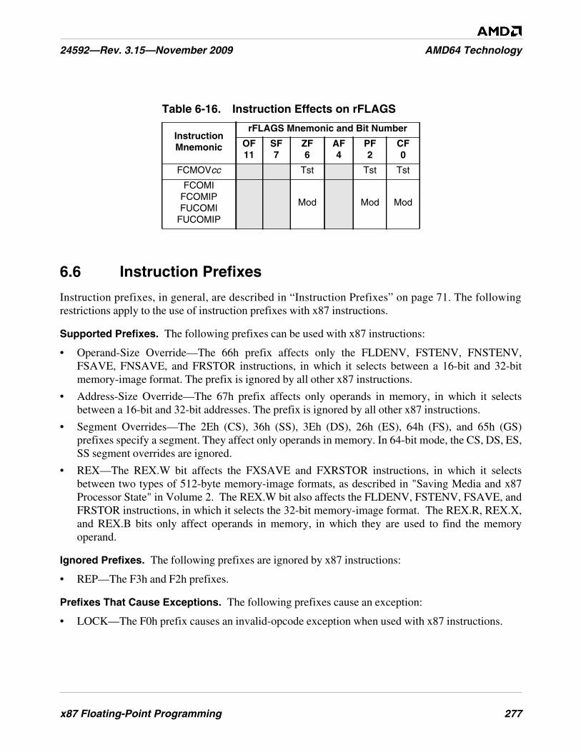
x87 Floating-Point Programming 277
24592—Rev. 3.15—November 2009 AMD64 Technology
6.6 Instruction Prefixes
Instruction prefixes, in general, are described in “Instruction Prefixes” on page 71. The followingrestrictions apply to the use of instruction prefixes with x87 instructions.
Supported Prefixes. The following prefixes can be used with x87 instructions:
• Operand-Size Override—The 66h prefix affects only the FLDENV, FSTENV, FNSTENV,FSAVE, FNSAVE, and FRSTOR instructions, in which it selects between a 16-bit and 32-bitmemory-image format. The prefix is ignored by all other x87 instructions.
• Address-Size Override—The 67h prefix affects only operands in memory, in which it selectsbetween a 16-bit and 32-bit addresses. The prefix is ignored by all other x87 instructions.
• Segment Overrides—The 2Eh (CS), 36h (SS), 3Eh (DS), 26h (ES), 64h (FS), and 65h (GS)prefixes specify a segment. They affect only operands in memory. In 64-bit mode, the CS, DS, ES,SS segment overrides are ignored.
• REX—The REX.W bit affects the FXSAVE and FXRSTOR instructions, in which it selectsbetween two types of 512-byte memory-image formats, as described in "Saving Media and x87Processor State" in Volume 2. The REX.W bit also affects the FLDENV, FSTENV, FSAVE, andFRSTOR instructions, in which it selects the 32-bit memory-image format. The REX.R, REX.X,and REX.B bits only affect operands in memory, in which they are used to find the memoryoperand.
Ignored Prefixes. The following prefixes are ignored by x87 instructions:
• REP—The F3h and F2h prefixes.
Prefixes That Cause Exceptions. The following prefixes cause an exception:
• LOCK—The F0h prefix causes an invalid-opcode exception when used with x87 instructions.
Table 6-16. Instruction Effects on rFLAGS
InstructionMnemonic
rFLAGS Mnemonic and Bit Number
OF11
SF7
ZF6
AF4
PF2
CF0
FCMOVcc Tst Tst Tst
FCOMIFCOMIPFUCOMI
FUCOMIP
Mod Mod Mod
278 x87 Floating-Point Programming
AMD64 Technology 24592—Rev. 3.15—November 2009
6.7 Feature Detection
Before executing x87 floating-point instructions, software should determine if the processor supportsthe technology by executing the CPUID instruction. “Feature Detection” on page 74 describes howsoftware uses the CPUID instruction to detect feature support. For full support of the x87 floating-point features, the following feature must be present:
• On-Chip Floating-Point Unit, indicated by bit 0 of CPUID function 1 and CPUID function8000_0001h.
• CMOVcc (conditional moves), indicated by bit 15 of CPUID function 1 and CPUID function8000_0001h. This bit indicates support for x87 floating-point conditional moves (FCMOVcc)whenever the On-Chip Floating-Point Unit bit (bit 0) is also set.
Software may also wish to check for the following support, because the FXSAVE and FXRSTORinstructions execute faster than FSAVE and FRSTOR:
• FXSAVE and FXRSTOR, indicated by bit 24 of CPUID function 1 and function 8000_0001h.
Software that runs in long mode should also check for the following support:
• Long Mode, indicated by bit 29 of CPUID function 8000_0001h.
See “Processor Feature Identification” in Volume 2 for a full description of the CPUID instruction andits function codes.
6.8 Exceptions
Types of Exceptions. x87 instructions can generate two types of exceptions:
• General-Purpose Exceptions, described below in “General-Purpose Exceptions”
• x87 Floating-Point Exceptions (#MF), described in “x87 Floating-Point Exception Causes” onpage 279
Relation to 128-Bit Media Exceptions. Although the x87 floating-point instructions and the 128-bitmedia instructions each have certain exceptions with the same names, the exception-reporting andexception-handling methods used by the two instruction subsets are distinct and independent of eachother. If procedures using both types of instructions are run in the same operating environment,separate service routines should be provided for the exceptions of each type of instruction subset.
6.8.1 General-Purpose Exceptions
The sections below list general-purpose exceptions generated and not generated by x87 floating-pointinstructions. For a summary of the general-purpose exception mechanism, see “Interrupts andExceptions” on page 86. For details about each exception and its potential causes, see “Exceptions andInterrupts” in Volume 2.
Exceptions Generated. x87 instructions can generate the following general-purpose exceptions:
x87 Floating-Point Programming 279
24592—Rev. 3.15—November 2009 AMD64 Technology
• #DB—Debug Exception (Vector 1)
• #BP—Breakpoint Exception (Vector 3)
• #UD—Invalid-Opcode Exception (Vector 6)
• #NM—Device-Not-Available Exception (Vector 7)
• #DF—Double-Fault Exception (Vector 8)
• #SS—Stack Exception (Vector 12)
• #GP—General-Protection Exception (Vector 13)
• #PF—Page-Fault Exception (Vector 14)
• #MF—x87 Floating-Point Exception-Pending (Vector 16)
• #AC—Alignment-Check Exception (Vector 17)
• #MC—Machine-Check Exception (Vector 18)
For details on #MF exceptions, see “x87 Floating-Point Exception Causes” below.
Exceptions Not Generated. x87 instructions do not generate the following general-purposeexceptions:
• #DE—Divide-by-zero-error exception (Vector 0)
• Non-Maskable-Interrupt Exception (Vector 2)
• #OF—Overflow exception (Vector 4)
• #BR—Bound-range exception (Vector 5)
• Coprocessor-segment-overrun exception (Vector 9)
• #TS—Invalid-TSS exception (Vector 10)
• #NP—Segment-not-present exception (Vector 11)
• #MC—Machine-check exception (Vector 18)
• #XF—SIMD floating-point exception (Vector 19)
For details on all general-purpose exceptions, see “Exceptions and Interrupts” in Volume 2.
6.8.2 x87 Floating-Point Exception Causes
The x87 floating-point exception-pending (#MF) exception listed above in “General-PurposeExceptions” is actually the logical OR of six exceptions that can be caused by x87 floating-pointinstructions. Each of the six exceptions has a status flag in the x87 status word and a mask bit in thex87 control word. A seventh exception, stack fault (SF), is reported together with one of the sixmaskable exceptions and does not have a mask bit.
If a #MF exception occurs when its mask bit is set to 1 (masked), the processor responds in a defaultway that does not invoke the #MF exception service routine. If an exception occurs when its mask bit iscleared to 0 (unmasked), the processor suspends processing of the faulting instruction (if possible) and,at the boundary of the next non-control x87 or 64-bit media instruction (see “Control” on page 273),
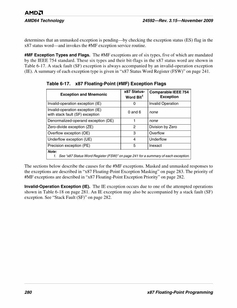
280 x87 Floating-Point Programming
AMD64 Technology 24592—Rev. 3.15—November 2009
determines that an unmasked exception is pending—by checking the exception status (ES) flag in thex87 status word—and invokes the #MF exception service routine.
#MF Exception Types and Flags. The #MF exceptions are of six types, five of which are mandatedby the IEEE 754 standard. These six types and their bit-flags in the x87 status word are shown inTable 6-17. A stack fault (SF) exception is always accompanied by an invalid-operation exception(IE). A summary of each exception type is given in “x87 Status Word Register (FSW)” on page 241.
The sections below describe the causes for the #MF exceptions. Masked and unmasked responses tothe exceptions are described in “x87 Floating-Point Exception Masking” on page 283. The priority of#MF exceptions are described in “x87 Floating-Point Exception Priority” on page 282.
Invalid-Operation Exception (IE). The IE exception occurs due to one of the attempted operationsshown in Table 6-18 on page 281. An IE exception may also be accompanied by a stack fault (SF)exception. See “Stack Fault (SF)” on page 282.
Table 6-17. x87 Floating-Point (#MF) Exception Flags
Exception and Mnemonicx87 Status-Word Bit1
Comparable IEEE 754Exception
Invalid-operation exception (IE) 0 Invalid Operation
Invalid-operation exception (IE)with stack fault (SF) exception
0 and 6 none
Denormalized-operand exception (DE) 1 none
Zero-divide exception (ZE) 2 Division by Zero
Overflow exception (OE) 3 Overflow
Underflow exception (UE) 4 Underflow
Precision exception (PE) 5 Inexact
Note:1. See “x87 Status Word Register (FSW)” on page 241 for a summary of each exception.
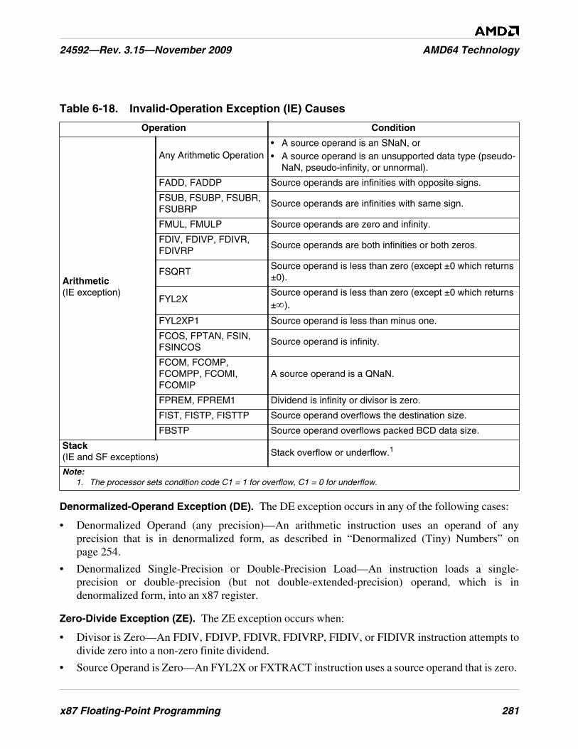
x87 Floating-Point Programming 281
24592—Rev. 3.15—November 2009 AMD64 Technology
Denormalized-Operand Exception (DE). The DE exception occurs in any of the following cases:
• Denormalized Operand (any precision)—An arithmetic instruction uses an operand of anyprecision that is in denormalized form, as described in “Denormalized (Tiny) Numbers” onpage 254.
• Denormalized Single-Precision or Double-Precision Load—An instruction loads a single-precision or double-precision (but not double-extended-precision) operand, which is indenormalized form, into an x87 register.
Zero-Divide Exception (ZE). The ZE exception occurs when:
• Divisor is Zero—An FDIV, FDIVP, FDIVR, FDIVRP, FIDIV, or FIDIVR instruction attempts todivide zero into a non-zero finite dividend.
• Source Operand is Zero—An FYL2X or FXTRACT instruction uses a source operand that is zero.
Table 6-18. Invalid-Operation Exception (IE) Causes
Operation Condition
Arithmetic(IE exception)
Any Arithmetic Operation• A source operand is an SNaN, or• A source operand is an unsupported data type (pseudo-
NaN, pseudo-infinity, or unnormal).
FADD, FADDP Source operands are infinities with opposite signs.
FSUB, FSUBP, FSUBR,FSUBRP
Source operands are infinities with same sign.
FMUL, FMULP Source operands are zero and infinity.
FDIV, FDIVP, FDIVR,FDIVRP
Source operands are both infinities or both zeros.
FSQRTSource operand is less than zero (except ±0 which returns±0).
FYL2XSource operand is less than zero (except ±0 which returns±∞).
FYL2XP1 Source operand is less than minus one.
FCOS, FPTAN, FSIN,FSINCOS
Source operand is infinity.
FCOM, FCOMP,FCOMPP, FCOMI,FCOMIP
A source operand is a QNaN.
FPREM, FPREM1 Dividend is infinity or divisor is zero.
FIST, FISTP, FISTTP Source operand overflows the destination size.
FBSTP Source operand overflows packed BCD data size.
Stack(IE and SF exceptions) Stack overflow or underflow.1
Note:1. The processor sets condition code C1 = 1 for overflow, C1 = 0 for underflow.
282 x87 Floating-Point Programming
AMD64 Technology 24592—Rev. 3.15—November 2009
Overflow Exception (OE). The OE exception occurs when the value of a rounded floating-pointresult is larger than the largest representable normalized positive or negative floating-point number inthe destination format, as shown in Table 6-5 on page 252. An overflow can occur throughcomputation or through conversion of higher-precision numbers to lower-precision numbers. See“Precision” on page 260. Integer and BCD overflow is reported via the invalid-operation exception.
Underflow Exception (UE). The UE exception occurs when the value of a rounded, non-zerofloating-point result is too small to be represented as a normalized positive or negative floating-pointnumber in the destination format, as shown in Table 6-5 on page 252. Integer and BCD underflow isreported via the invalid-operation exception.
Precision Exception (PE). The PE exception, also called the inexact-result exception, occurs when afloating-point result, after rounding, differs from the infinitely precise result and thus cannot berepresented exactly in the specified destination format. Software that does not require exact resultsnormally masks this exception. See “Precision” on page 260 and “Rounding” on page 260.
Stack Fault (SF). The SF exception occurs when a stack overflow (due to a push or load into a non-empty stack register) or stack underflow (due to referencing an empty stack register) occurs in the x87stack-register file. The empty and non-empty conditions are shown in Table 6-3 on page 246. Wheneither of these conditions occur, the processor also sets the invalid-operation exception (IE) flag, and itsets or clears the condition-code 1 (C1) bit to indicate the direction of the stack fault (C1 = 1 foroverflow, C1 = 0 for underflow). Unlike the flags for the other x87 exceptions, the SF flag does nothave a corresponding mask bit in the x87 control word.
6.8.3 x87 Floating-Point Exception Priority
Table 6-19 shows the priority with which the processor recognizes multiple, simultaneous SIMDfloating-point exceptions and operations involving QNaN operands. Each exception type ischaracterized by its timing, as follows:
• Pre-Computation—an exception that is recognized before an instruction begins its operation.
• Post-Computation—an exception that is recognized after an instruction completes its operation.
For post-computation exceptions, a result may be written to the destination, depending on the type ofexception and whether the destination is a register or memory location. Operations involving QNaNsdo not necessarily cause exceptions, but the processor handles them with the priority shown inTable 6-19 on page 283 relative to the handling of exceptions.
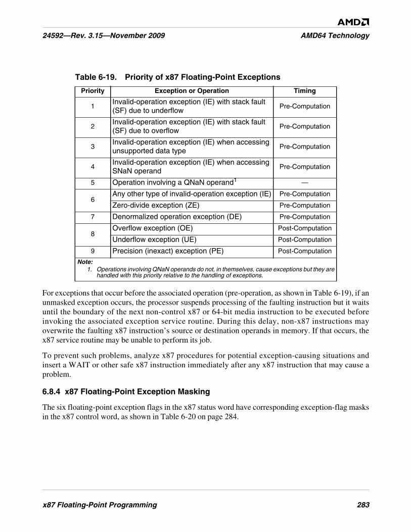
x87 Floating-Point Programming 283
24592—Rev. 3.15—November 2009 AMD64 Technology
For exceptions that occur before the associated operation (pre-operation, as shown in Table 6-19), if anunmasked exception occurs, the processor suspends processing of the faulting instruction but it waitsuntil the boundary of the next non-control x87 or 64-bit media instruction to be executed beforeinvoking the associated exception service routine. During this delay, non-x87 instructions mayoverwrite the faulting x87 instruction’s source or destination operands in memory. If that occurs, thex87 service routine may be unable to perform its job.
To prevent such problems, analyze x87 procedures for potential exception-causing situations andinsert a WAIT or other safe x87 instruction immediately after any x87 instruction that may cause aproblem.
6.8.4 x87 Floating-Point Exception Masking
The six floating-point exception flags in the x87 status word have corresponding exception-flag masksin the x87 control word, as shown in Table 6-20 on page 284.
Table 6-19. Priority of x87 Floating-Point Exceptions
Priority Exception or Operation Timing
1Invalid-operation exception (IE) with stack fault(SF) due to underflow
Pre-Computation
2Invalid-operation exception (IE) with stack fault(SF) due to overflow
Pre-Computation
3Invalid-operation exception (IE) when accessingunsupported data type
Pre-Computation
4Invalid-operation exception (IE) when accessingSNaN operand
Pre-Computation
5 Operation involving a QNaN operand1 —
6Any other type of invalid-operation exception (IE) Pre-Computation
Zero-divide exception (ZE) Pre-Computation
7 Denormalized operation exception (DE) Pre-Computation
8Overflow exception (OE) Post-Computation
Underflow exception (UE) Post-Computation
9 Precision (inexact) exception (PE) Post-Computation
Note:1. Operations involving QNaN operands do not, in themselves, cause exceptions but they are
handled with this priority relative to the handling of exceptions.

284 x87 Floating-Point Programming
AMD64 Technology 24592—Rev. 3.15—November 2009
Each mask bit, when set to 1, inhibits invocation of the #MF exception handler and instead continuesnormal execution using the default response for the exception type. During initialization with FINIT orFNINIT, all exception-mask bits in the x87 control word are set to 1 (masked). At processor reset, allexception-mask bits are cleared to 0 (unmasked).
Masked Responses. The occurrence of a masked exception does not invoke its exception handlerwhen the exception condition occurs. Instead, the processor handles masked exceptions in a defaultway, as shown in Table 6-21 on page 285.
Table 6-20. x87 Floating-Point (#MF) Exception Masks
Exception Maskand Mnemonic
x87 Control-WordBit1
Invalid-operation exception mask (IM) 0
Denormalized-operand exception mask (DM) 1
Zero-divide exception mask (ZM) 2
Overflow exception mask (OM) 3
Underflow exception mask (UM) 4
Precision exception mask (PM) 5
Note:1. See “x87 Status Word Register (FSW)” on page 241 for a summary of each exception.

x87 Floating-Point Programming 285
24592—Rev. 3.15—November 2009 AMD64 Technology
Table 6-21. Masked Responses to x87 Floating-Point Exceptions
Exception andMnemonic
Type ofOperation1 Processor Response
Invalid-operationexception (IE)2
Any Arithmetic Operation:Source operand is an SNaN.
Set IE flag, and return a QNaN value.
Any Arithmetic Operation:Source operand is anunsupported data typeorFADD, FADDP: Sourceoperands are infinities withopposite signsorFSUB, FSUBP, FSUBR,FSUBRP: Source operands areinfinities with same signorFMUL, FMULP: Sourceoperands are zero and infinityorFDIV, FDIVP, FDIVR, FDIVRP:Source operands are bothinfinities or both are zerosorFSQRT: Source operand is lessthan zero (except ±0 whichreturns ±0)orFYL2X: Source operand is lessthan zero (except ±0 whichreturns ±∞)
orFYL2XP1: Source operand isless than minus one.
Set IE flag, and return the floating-point indefinite
value3.
Note:1. See “Instruction Summary” on page 261 for the types of instructions.2. Includes invalid-operation exception (IE) together with stack fault (SF).3. See “Indefinite Values” on page 258.
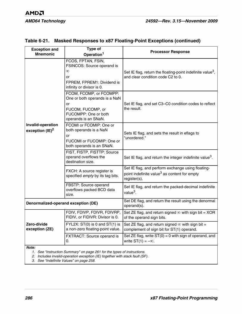
286 x87 Floating-Point Programming
AMD64 Technology 24592—Rev. 3.15—November 2009
Invalid-operationexception (IE)2
FCOS, FPTAN, FSIN,FSINCOS: Source operand is∞orFPREM, FPREM1: Dividend isinfinity or divisor is 0.
Set IE flag, return the floating-point indefinite value3,and clear condition code C2 to 0.
FCOM, FCOMP, or FCOMPP:One or both operands is a NaNorFUCOM, FUCOMP, orFUCOMPP: One or bothoperands is an SNaN.
Set IE flag, and set C3–C0 condition codes to reflectthe result.
FCOMI or FCOMIP: One orboth operands is a NaNorFUCOMI or FUCOMIP: One orboth operands is an SNaN.
Sets IE flag, and sets the result in eflags to"unordered."
FIST, FISTP, FISTTP: Sourceoperand overflows thedestination size.
Set IE flag, and return the integer indefinite value3.
FXCH: A source register isspecified empty by its tag bits.
Set IE flag, and perform exchange using floating-
point indefinite value3 as content for emptyregister(s).
FBSTP: Source operandoverflows packed BCD datasize.
Set IE flag, and return the packed-decimal indefinite
value3.
Denormalized-operand exception (DE)Set DE flag, and return the result using the denormaloperand(s).
Zero-divideexception (ZE)
FDIV, FDIVP, FDIVR, FDIVRP,FIDIV, or FIDIVR: Divisor is 0.
Set ZE flag, and return signed ∞ with sign bit = XORof the operand sign bits.
FYL2X: ST(0) is 0 and ST(1) isa non-zero floating-point value.
Set ZE flag, and return signed ∞ with sign bit =complement of sign bit for ST(1) operand.
FXTRACT: Source operand is0.
Set ZE flag, write ST(0) = 0 with sign of operand, andwrite ST(1) = –∞.
Table 6-21. Masked Responses to x87 Floating-Point Exceptions (continued)
Exception andMnemonic
Type ofOperation1 Processor Response
Note:1. See “Instruction Summary” on page 261 for the types of instructions.2. Includes invalid-operation exception (IE) together with stack fault (SF).3. See “Indefinite Values” on page 258.
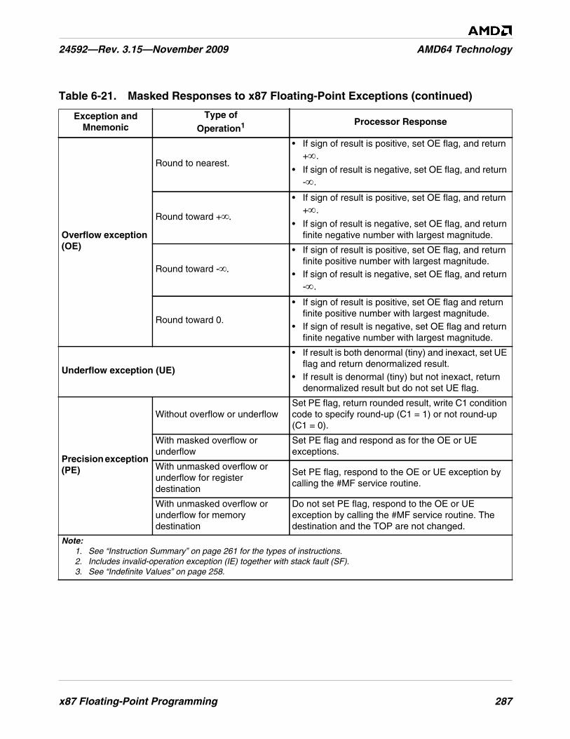
x87 Floating-Point Programming 287
24592—Rev. 3.15—November 2009 AMD64 Technology
Overflow exception(OE)
Round to nearest.
• If sign of result is positive, set OE flag, and return+∞.
• If sign of result is negative, set OE flag, and return-∞.
Round toward +∞.
• If sign of result is positive, set OE flag, and return+∞.
• If sign of result is negative, set OE flag, and returnfinite negative number with largest magnitude.
Round toward -∞.
• If sign of result is positive, set OE flag, and returnfinite positive number with largest magnitude.
• If sign of result is negative, set OE flag, and return-∞.
Round toward 0.
• If sign of result is positive, set OE flag and returnfinite positive number with largest magnitude.
• If sign of result is negative, set OE flag and returnfinite negative number with largest magnitude.
Underflow exception (UE)
• If result is both denormal (tiny) and inexact, set UEflag and return denormalized result.
• If result is denormal (tiny) but not inexact, returndenormalized result but do not set UE flag.
Precision exception(PE)
Without overflow or underflowSet PE flag, return rounded result, write C1 conditioncode to specify round-up (C1 = 1) or not round-up(C1 = 0).
With masked overflow orunderflow
Set PE flag and respond as for the OE or UEexceptions.
With unmasked overflow orunderflow for registerdestination
Set PE flag, respond to the OE or UE exception bycalling the #MF service routine.
With unmasked overflow orunderflow for memorydestination
Do not set PE flag, respond to the OE or UEexception by calling the #MF service routine. Thedestination and the TOP are not changed.
Table 6-21. Masked Responses to x87 Floating-Point Exceptions (continued)
Exception andMnemonic
Type ofOperation1 Processor Response
Note:1. See “Instruction Summary” on page 261 for the types of instructions.2. Includes invalid-operation exception (IE) together with stack fault (SF).3. See “Indefinite Values” on page 258.
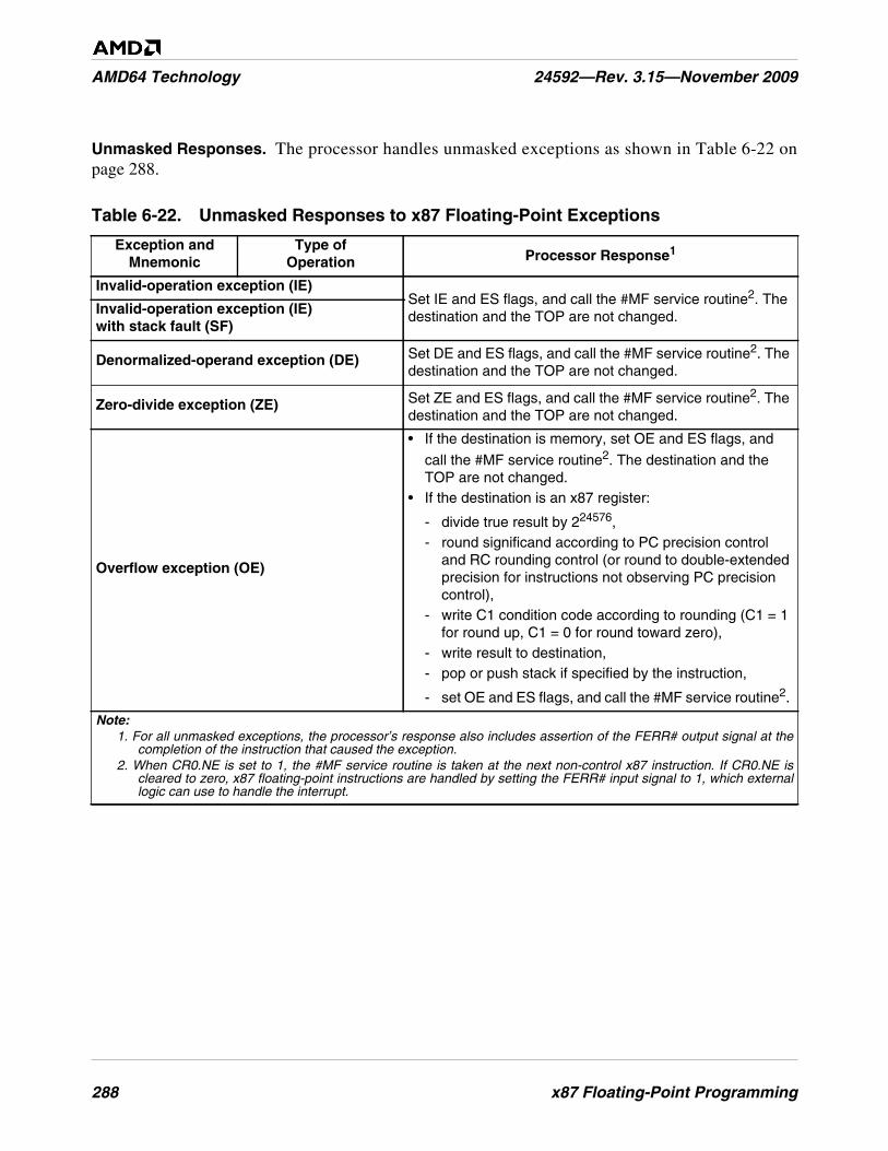
288 x87 Floating-Point Programming
AMD64 Technology 24592—Rev. 3.15—November 2009
Unmasked Responses. The processor handles unmasked exceptions as shown in Table 6-22 onpage 288.
Table 6-22. Unmasked Responses to x87 Floating-Point Exceptions
Exception andMnemonic
Type ofOperation Processor Response1
Invalid-operation exception (IE)Set IE and ES flags, and call the #MF service routine2. Thedestination and the TOP are not changed.Invalid-operation exception (IE)
with stack fault (SF)
Denormalized-operand exception (DE) Set DE and ES flags, and call the #MF service routine2. Thedestination and the TOP are not changed.
Zero-divide exception (ZE) Set ZE and ES flags, and call the #MF service routine2. Thedestination and the TOP are not changed.
Overflow exception (OE)
• If the destination is memory, set OE and ES flags, and
call the #MF service routine2. The destination and theTOP are not changed.
• If the destination is an x87 register:
- divide true result by 224576,- round significand according to PC precision control
and RC rounding control (or round to double-extendedprecision for instructions not observing PC precisioncontrol),
- write C1 condition code according to rounding (C1 = 1for round up, C1 = 0 for round toward zero),
- write result to destination,- pop or push stack if specified by the instruction,
- set OE and ES flags, and call the #MF service routine2.
Note:1. For all unmasked exceptions, the processor’s response also includes assertion of the FERR# output signal at the
completion of the instruction that caused the exception.2. When CR0.NE is set to 1, the #MF service routine is taken at the next non-control x87 instruction. If CR0.NE is
cleared to zero, x87 floating-point instructions are handled by setting the FERR# input signal to 1, which externallogic can use to handle the interrupt.
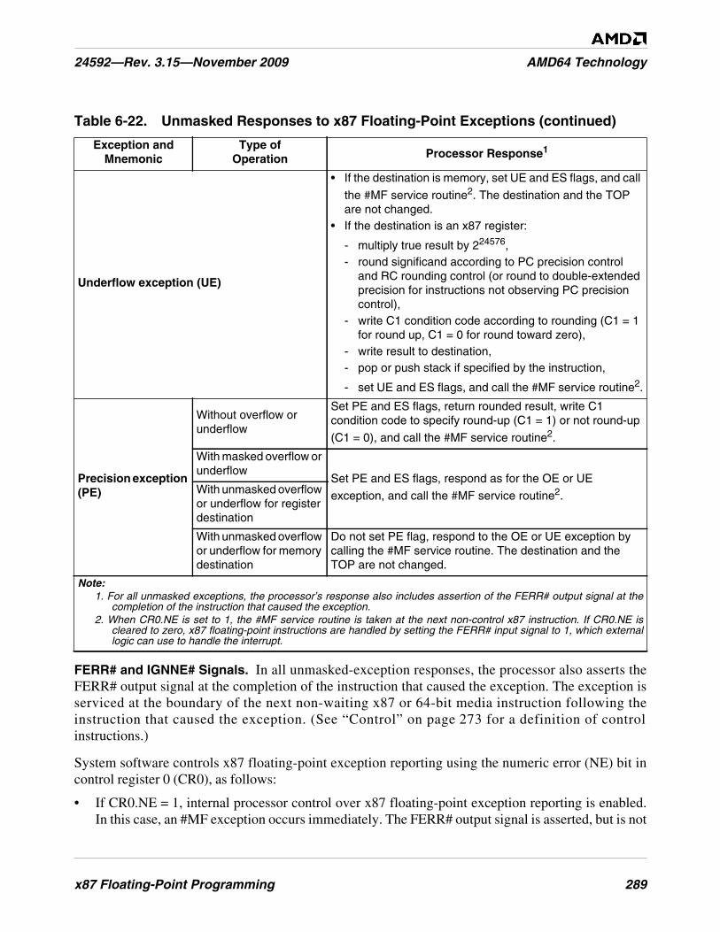
x87 Floating-Point Programming 289
24592—Rev. 3.15—November 2009 AMD64 Technology
FERR# and IGNNE# Signals. In all unmasked-exception responses, the processor also asserts theFERR# output signal at the completion of the instruction that caused the exception. The exception isserviced at the boundary of the next non-waiting x87 or 64-bit media instruction following theinstruction that caused the exception. (See “Control” on page 273 for a definition of controlinstructions.)
System software controls x87 floating-point exception reporting using the numeric error (NE) bit incontrol register 0 (CR0), as follows:
• If CR0.NE = 1, internal processor control over x87 floating-point exception reporting is enabled.In this case, an #MF exception occurs immediately. The FERR# output signal is asserted, but is not
Underflow exception (UE)
• If the destination is memory, set UE and ES flags, and call
the #MF service routine2. The destination and the TOPare not changed.
• If the destination is an x87 register:
- multiply true result by 224576,- round significand according to PC precision control
and RC rounding control (or round to double-extendedprecision for instructions not observing PC precisioncontrol),
- write C1 condition code according to rounding (C1 = 1for round up, C1 = 0 for round toward zero),
- write result to destination,- pop or push stack if specified by the instruction,
- set UE and ES flags, and call the #MF service routine2.
Precision exception(PE)
Without overflow orunderflow
Set PE and ES flags, return rounded result, write C1condition code to specify round-up (C1 = 1) or not round-up
(C1 = 0), and call the #MF service routine2.
With masked overflow orunderflow
Set PE and ES flags, respond as for the OE or UE
exception, and call the #MF service routine2.With unmasked overflowor underflow for registerdestination
With unmasked overflowor underflow for memorydestination
Do not set PE flag, respond to the OE or UE exception bycalling the #MF service routine. The destination and theTOP are not changed.
Table 6-22. Unmasked Responses to x87 Floating-Point Exceptions (continued)
Exception andMnemonic
Type ofOperation Processor Response1
Note:1. For all unmasked exceptions, the processor’s response also includes assertion of the FERR# output signal at the
completion of the instruction that caused the exception.2. When CR0.NE is set to 1, the #MF service routine is taken at the next non-control x87 instruction. If CR0.NE is
cleared to zero, x87 floating-point instructions are handled by setting the FERR# input signal to 1, which externallogic can use to handle the interrupt.
290 x87 Floating-Point Programming
AMD64 Technology 24592—Rev. 3.15—November 2009
used externally. It is recommended that system software set NE to 1. This enables optimalperformance in handling x87 floating-point exceptions.
• If CR0.NE = 0, internal processor control of x87 floating-point exceptions is disabled and theexternal IGNNE# input signal controls whether x87 floating-point exceptions are ignored, asfollows:
- When IGNNE# is 0, x87 floating-point exceptions are reported by asserting the FERR# outputsignal, then stopping program execution until an external interrupt is detected. External logicuse the FERR# signal to generate the external interrupt.
- When IGNNE# is 1, x87 floating-point exceptions do not stop program execution. AfterFERR# is asserted, instructions continue to execute.
Using NaNs in IE Diagnostic Exceptions. Both SNaNs and QNaNs can be encoded with manydifferent values to carry diagnostic information. By means of appropriate masking and unmasking ofthe invalid-operation exception (IE), software can use signaling NaNs to invoke an exception handler.Within the constraints imposed by the encoding of SNaNs and QNaNs, software may freely assign thebits in the significand of a NaN. See the section “Not a Number (NaN)” on page 255 for format details.
For example, software can pre-load each element of an array with a signaling NaN that encodes thearray index. When an application accesses an uninitialized array element, the invalid-operationexception is invoked and the service routine can identify that element. A service routine can storedebug information in memory as the exceptions occur. The routine can create a QNaN that referencesits associated debug area in memory. As the program runs, the service routine can create a differentQNaN for each error condition, so that a single test-run can identify a collection of errors.
6.9 State-Saving
In general, system software should save and restore x87 state between task switches or otherinterventions in the execution of x87 floating-point procedures. Virtually all modern operating systemsrunning on x86 processors implement preemptive multitasking that handle saving and restoring ofstate across task switches, independent of hardware task-switch support. However, applicationprocedures are also free to save and restore x87 state at any time they deem useful.
6.9.1 State-Saving Instructions
FSAVE/FNSAVE and FRSTOR Instructions. Application software can save and restore the x87state by executing the FSAVE (or FNSAVE) and FRSTOR instructions. Alternatively, software mayuse multiple FxSTx (floating-point store stack top) instructions for saving only the contents of the x87data registers, rather than the complete x87 state.
The FSAVE instruction stores the state, but only after handling any pending unmasked x87 floating-point exceptions, whereas the FNSAVE instruction skips the handling of these exceptions. The state ofall x87 data registers is saved, as well as all x87 environment state (the x87 control word register, statusword register, tag word, instruction pointer, data pointer, and last opcode register). After saving thisstate, the tag bits for all x87 registers are changed to empty and thus available for a new procedure.

x87 Floating-Point Programming 291
24592—Rev. 3.15—November 2009 AMD64 Technology
FXSAVE and FXRSTOR Instructions. Application software can save and restore the 128-bit mediastate, 64-bit media state, and x87 floating-point state by executing the FXSAVE and FXRSTORinstructions. The FXSAVE and FXRSTOR instructions execute faster than FSAVE/FNSAVE andFRSTOR because they do not save and restore the x87 pointers (last instruction pointer, last datapointer, and last opcode, described in “Pointers and Opcode State” on page 247) except in therelatively rare cases in which the exception-summary (ES) bit in the x87 status word (the ES registerimage for FXSAVE, or the ES memory image for FXRSTOR) is set to 1, indicating that an unmaskedx87 exception has occurred.
Unlike FSAVE and FNSAVE, however, FXSAVE does not alter the tag bits. The state of the saved x87data registers is retained, thus indicating that the registers may still be valid (or whatever other valuethe tag bits indicated prior to the save). To invalidate the contents of the x87 data registers afterFXSAVE, software must explicitly execute an FINIT instruction. Also, FXSAVE (like FNSAVE) andFXRSTOR do not check for pending unmasked x87 floating-point exceptions. An FWAIT instructioncan be used for this purpose.
The architecture supports two memory formats for FXSAVE and FXRSTOR, a 512-byte 32-bit legacyformat and a 512-byte 64-bit format, used in 64-bit mode. Selection of the 32-bit or 64-bit format isdetermined by the effective operand size for the FXSAVE and FXRSTOR instructions. For details, see“Media and x87 Processor State” in Volume 2.
6.10 Performance Considerations
In addition to typical code optimization techniques, such as those affecting loops and the inlining offunction calls, the following considerations may help improve the performance of applicationprograms written with x87 floating-point instructions.
These are implementation-independent performance considerations. Other considerations depend onthe hardware implementation. For information about such implementation-dependent considerationsand for more information about application performance in general, see the data sheets and thesoftware-optimization guides relating to particular hardware implementations.
6.10.1 Replace x87 Code with 128-Bit Media Code
Code written with 128-bit media floating-point instructions can operate in parallel on four times asmany single-precision floating-point operands as can x87 floating-point code. This achievespotentially four times the computational work of x87 instructions that use single-precision operands.Also, the higher density of 128-bit media floating-point operands may make it possible to remove localtemporary variables that would otherwise be needed in x87 floating-point code. 128-bit media code iseasier to write than x87 floating-point code, because the XMM register file is flat rather than stack-oriented, and, in 64-bit mode there are twice the number of XMM registers as x87 registers.
6.10.2 Use FCOMI-FCMOVx Branching
Depending on the hardware implementation of the architecture, the combination of FCOMI andFCMOVcc is often faster than the classical approach using FxSTSW AX instructions for comparison-
292 x87 Floating-Point Programming
AMD64 Technology 24592—Rev. 3.15—November 2009
based branches that depend on the condition codes for branch direction, because FNSTSW AX is oftena serializing instruction.
6.10.3 Use FSINCOS Instead of FSIN and FCOS
Frequently, a piece of code that needs to compute the sine of an argument also needs to compute thecosine of that same argument. In such cases, use the FSINCOS instruction to compute bothtrigonometric functions concurrently, which is faster than using separate FSIN and FCOS instructionsto accomplish the same task.
6.10.4 Break Up Dependency Chains
Parallelism can be increased by breaking up dependency chains or by evaluating multiple dependencychains simultaneously (explicitly switching execution between them). Depending on the hardwareimplementation of the architecture, the FXCH instruction may prove faster than FST/FLD pairs forswitching execution between dependency chains.

Index 293
24592—Rev. 3.15—November 2009 AMD64 Technology
Symbols
#AC exception......................................................... 88#BP exception ......................................................... 87#BR exception......................................................... 87#DB exception......................................................... 87#DE exception......................................................... 87#DF exception ......................................................... 87#GP exception ......................................................... 88#MC exception ........................................................ 88#MF exception ......................................... 88, 231, 243#NM exception........................................................ 87#NP exception ......................................................... 87#OF exception ......................................................... 87#PF exception.......................................................... 88#SS exception.......................................................... 88#TS exception ......................................................... 87#UD exception ................................................ 87, 179#XF exception ................................................. 88, 179
Numerics
128-bit media programming.................................... 10516-bit mode .......................................................... xviii32-bit mode ............................................................ xix3DNow!/tm technology .............................................. 43DNow!™ instructions .......................................... 19364-bit media programming ..................................... 19364-bit mode ........................................................ xix, 6
A
AAA instruction ................................................ 47, 69AAD instruction ................................................ 47, 69AAM instruction................................................ 47, 69AAS instruction................................................. 47, 69aborts...................................................................... 87absolute address....................................................... 15ADC instruction ...................................................... 50ADD instruction ...................................................... 50addition................................................................... 50ADDPD instruction................................................ 166ADDPS instruction ................................................ 166addressing
absolute address ................................................... 15address size............................................... 17, 67, 72branch address...................................................... 68canonical form ..................................................... 15complex address ................................................... 16effective address................................................... 15I/O ports ..................................................... 123, 203
IP-relative ...................................................... 16, 18linear ............................................................. 11, 12memory................................................................ 14operands................................................ 40, 123, 203PC-relative ..................................................... 16, 18RIP-relative ................................................. xxiv, 18stack address ........................................................ 16string address........................................................ 16virtual ............................................................ 11, 12x87 stack............................................................ 240
ADDSD instruction ................................................ 166ADDSS instruction................................................. 166ADDSUBPD instruction......................................... 169ADDSUBPS instruction ......................................... 169AF bit...................................................................... 35affine ordering ............................................... 130, 256AH register ........................................................ 25, 26AL register ........................................................ 25, 26alignment
128-bit media ............................................. 123, 19064-bit media ....................................................... 204general-purpose ............................................ 40, 101
AND instruction....................................................... 56ANDNPD instruction ............................................. 174ANDNPS instruction .............................................. 174ANDPD instruction ................................................ 174ANDPS instruction................................................. 174arithmetic instructions ........ 50, 145, 166, 216, 225, 266ARPL instruction ..................................................... 70array bounds ............................................................ 56ASCII adjust instructions .......................................... 47AX register ........................................................ 25, 26
B
B bit...................................................................... 244BCD data type ....................................................... 252BCD digits .............................................................. 38BH register ........................................................ 25, 26biased exponent ........................ xix, 126, 131, 251, 257binary-coded-decimal (BCD) digits ........................... 38bit scan instructions.................................................. 54bit strings................................................................. 38bit test instructions ................................................... 54BL register ........................................................ 25, 26BOUND instruction............................................ 56, 69BP register......................................................... 25, 26BPL register ............................................................ 26branch removal ............................... 114, 154, 198, 221branch-address displacements ................................... 68
Index

294 Index
AMD64 Technology 24592—Rev. 3.15—November 2009
branches............................................. 76, 84, 101, 189BSF instruction........................................................ 54BSR instruction ....................................................... 54BSWAP instruction.................................................. 48BT instruction ......................................................... 54BTC instruction ....................................................... 54BTR instruction ....................................................... 54BTS instruction ....................................................... 54busy (B) bit ........................................................... 244BX register........................................................ 25, 26byte ordering ..................................................... 14, 48byte registers ........................................................... 29
C
C3–C0 bits ............................................................ 243cache ...................................................................... 96
cachability ......................................................... 190coherency ............................................................ 98line...................................................................... 97management................................................... 66, 99pollution .............................................................. 98prefetching........................................................... 99stale lines ........................................................... 100
cache management instructions ................................. 66CALL instruction.......................................... 60, 69, 79caller-save parameter passing.................................. 188canonical address form............................................. 15carry flag................................................................. 35CBW instruction...................................................... 46CDQ instruction ...................................................... 46CDQE instruction .................................................... 46CF bit ..................................................................... 35CH register........................................................ 25, 26CL register ........................................................ 25, 26clamping ............................................................... 125CLC instruction ....................................................... 63CLD instruction....................................................... 63clearing the MMX state ........................... 189, 209, 233CLFLUSH instruction .............................................. 66CLI instruction ........................................................ 63CMC instruction ...................................................... 63CMOVcc instructions............................................... 42CMP instruction ...................................................... 53CMPPD instruction................................................ 172CMPPS instruction ................................................ 171CMPS instruction .................................................... 57CMPSB instruction .................................................. 57CMPSD instruction.......................................... 57, 172CMPSQ instruction.................................................. 57CMPSS instruction ................................................ 172CMPSW instruction ................................................. 57CMPXCHG instruction ............................................ 65
CMPXCHG16B instruction ...................................... 65CMPXCHG8B instruction ........................................ 65COMISD instruction .............................................. 173COMISS instruction ............................................... 173commit............................................................. xix, 93compare instructions........... 53, 153, 171, 220, 228, 270compatibility mode.............................................. xix, 7complex address....................................................... 16condition codes (C3–C0) ........................................ 243conditional moves ............................................ 42, 264constants ............................................................... 265control instructions (x87) ........................................ 273control transfers ........................................... 16, 58, 76control word .......................................................... 244CPUID instruction........................ 65, 74, 176, 229, 278CQO instruction....................................................... 46CR0.EM bit ........................................................... 249CVTDQ2PD instruction.......................................... 139CVTDQ2PS instruction .......................................... 139CVTPD2DQ instruction.......................................... 163CVTPD2PI instruction.................................... 163, 224CVTPD2PS instruction........................................... 162CVTPI2PD instruction.................................... 139, 212CVTPI2PS instruction .................................... 139, 212CVTPS2DQ instruction .......................................... 163CVTPS2PD instruction........................................... 162CVTPS2PI instruction .................................... 163, 224CVTSD2SI instruction............................................ 164CVTSD2SS instruction........................................... 162CVTSI2SD instruction............................................ 140CVTSI2SS instruction ............................................ 140CVTSS2SD instruction........................................... 162CVTSS2SI instruction ............................................ 164CVTTPD2DQ instruction ....................................... 163CVTTPD2PI instruction ................................. 163, 224CVTTPS2DQ instruction........................................ 163CVTTPS2PI instruction .................................. 163, 224CVTTSD2SI instruction ......................................... 164CVTTSS2SI instruction .......................................... 164CWD instruction ...................................................... 46CWDE instruction.................................................... 46CX register ........................................................ 25, 26
D
DAA instruction................................................. 48, 69DAS instruction ................................................. 48, 69data conversion instructions 46, 139, 162, 211, 224, 263data reordering instructions ...................... 140, 165, 212data transfer instructions ............. 42, 135, 157, 209, 263data types
128-bit media ..................................................... 121128-bit media floating-point ................................ 130
Index 295
24592—Rev. 3.15—November 2009 AMD64 Technology
64-bit media....................................................... 201general-purpose .................................................... 36mismatched........................................................ 188x87............................................................. 250, 256
DAZ bit ................................................................ 119DE bit ..................................... 118, 119, 181, 242, 281DEC instruction................................................. 51, 70decimal adjust instructions........................................ 48decrement ............................................................... 51default address size .................................................. 17default operand size ................................................. 29denormalized numbers .................................... 128, 254denormalized-operand exception (DE).............. 181, 281dependencies ......................................................... 102DF bit ..................................................................... 35DH register........................................................ 25, 26DI register ......................................................... 25, 26DIL register............................................................. 26direct far jump ................................................... 58, 61direct referencing..................................................... xxdirection flag ........................................................... 35displacements ............................................... xx, 17, 68DIV instruction........................................................ 50division................................................................... 50DIVPD instruction ................................................. 170DIVPS instruction.................................................. 170DIVSD instruction ................................................. 170DIVSS instruction.................................................. 170DL register ........................................................ 25, 26DM bit ........................................................... 119, 244dot product ..................................................... 112, 197double quadword ..................................................... xxdouble-extended-precision format ........................... 252double-precision format................................... 127, 252doubleword ............................................................. xxDX register........................................................ 25, 26
E
EAX register ..................................................... 25, 26eAX–eSP register ................................................. xxviEBP register ...................................................... 25, 26EBX register...................................................... 25, 26ECX register...................................................... 25, 26EDI register....................................................... 25, 26EDX register ..................................................... 25, 26effective address ................................................ 15, 49effective address size ............................................... xxeffective operand size......................................... xx, 39EFLAGS register ............................................... 25, 33eFLAGS register................................................... xxviEIP register ............................................................. 20eIP register ........................................................... xxvi
element ................................................................... xxEM bit................................................................... 249EMMS instruction.......................................... 209, 233empty............................................................ 232, 246emulation (EM) bit ................................................. 249endian byte-ordering................................ xxviii, 14, 48ENTER instruction................................................... 44environment
x87 ............................................................ 248, 275ES bit .................................................................... 243ESI register........................................................ 25, 26ESP register ....................................................... 25, 26exception status (ES) bit ......................................... 243exceptions ......................................................... xx, 86
#MF causes ................................................ 231, 279#XF causes......................................................... 178128-bit media ..................................................... 17764-bit media ....................................................... 230denormalized-operand (DE)......................... 181, 281general-purpose .................................................... 86inexact-result .............................................. 181, 282invalid-operation (IE).................................. 180, 280masked responses........................................ 184, 284masking ..................................................... 184, 283overflow (OE) ............................................ 181, 282post-computation ........................................ 182, 282precision (PE)............................................. 181, 282pre-computation.......................................... 182, 282priority....................................................... 182, 282SIMD floating-point causes ................................. 178stack fault (SF) ................................................... 282underflow (UE)........................................... 181, 282unmasked responses ............................................ 288x87 .................................................................... 278zero-divide (ZE) ......................................... 181, 281
exit media state ...................................................... 209explicit integer bit .................................................. 251exponent................................... xix, 126, 131, 251, 257extended functions ................................................... 75external interrupts .................................................... 86extract instructions .................................. 143, 214, 265EXTRQ................................................................. 143
F
F2XM1 instruction ................................................. 270FABS instruction ................................................... 268FADD instruction................................................... 266FADDP instruction................................................. 266far calls ................................................................... 80far jumps ................................................................. 78far returns ................................................................ 82fault ........................................................................ 87FBLD instruction ................................................... 264
296 Index
AMD64 Technology 24592—Rev. 3.15—November 2009
FBSTP instruction ................................................. 264FCMOVcc instructions........................................... 264FCOM instruction.................................................. 271FCOMI instruction................................................. 271FCOMIP instruction............................................... 271FCOMP instruction................................................ 271FCOMPP instruction.............................................. 271FCOS instruction ................................................... 269FCW register ......................................................... 244FDECSTP instruction............................................. 273FDIV instruction.................................................... 268FDIVP instruction.................................................. 268FDIVR instruction ................................................. 268FDIVRP instruction ............................................... 268feature detection ...................................................... 74FEMMS instruction ........................................ 209, 233FERR ................................................................... 289FFREE instruction ................................................. 273FICOM instruction................................................. 272FICOMP instruction............................................... 272FIDIV instruction .................................................. 268FIMUL instruction................................................. 267FINCSTP instruction.............................................. 273FINIT instruction................................................... 274FIST instruction..................................................... 264FISTP instruction................................................... 264FISTTP instruction ................................................ 264FISUB instruction.................................................. 267flags instructions...................................................... 62FLAGS register ................................................. 25, 33FLD instruction ..................................................... 263FLD1 instruction ................................................... 265FLDL2E instruction ............................................... 266FLDL2T instruction ............................................... 266FLDLG2 instruction............................................... 266FLDLN2 instruction............................................... 266FLDPI instruction .................................................. 265FLDZ instruction ................................................... 265floating-point data types
128-bit media ..................................................... 1263DNow! ™ ........................................................ 20564-bit media....................................................... 205x87.................................................................... 251
floating-point instructions........................................... 5flush ...................................................................... xxiflush-to-zero (FZ) bit ............................................. 120FMUL instruction .................................................. 267FMULP instruction ................................................ 267FNINIT instruction ................................................ 274FNOP instruction................................................... 273FNSAVE instruction ............................... 223, 234, 276FPATAN instruction .............................................. 269
FPR0–FPR7 registers ............................................. 240FPREM instruction................................................. 268FPREM1 instruction............................................... 269FPTAN instruction ................................................. 269FPU control word................................................... 244FPU status word..................................................... 241FRNDINT instruction............................................. 268FRSTOR instruction................................ 223, 234, 276FS register ............................................................... 17FSAVE instruction .................................. 223, 234, 276FSCALE instruction ............................................... 270FSIN instruction..................................................... 269FSINCOS instruction.............................................. 269FST instruction ...................................................... 263FSTP instruction .................................................... 263FSUB instruction ................................................... 267FSUBP instruction ................................................. 267FSUBR instruction ................................................. 267FSUBRP instruction ............................................... 267FSW register.......................................................... 241FTST instruction .................................................... 272FTW register ......................................................... 246FUCOMx instructions ............................................ 272full ................................................................ 232, 246FXAM instruction .................................................. 272FXCH instruction................................................... 265FXRSTOR instruction ..................... 156, 223, 234, 276FXSAVE instruction ....................... 156, 223, 234, 276FXTRACT instruction ............................................ 265FYL2X instruction ................................................. 270FYL2XP1 instruction ............................................. 270FZ bit .................................................................... 120
G
general-purpose instructions....................................... 4general-purpose registers (GPRs) .............................. 23GPR......................................................................... 3GPR registers........................................................... 23GS register .............................................................. 17
H
HADDPD instruction ..................................... 167, 168HADDPS instruction .............................................. 167hidden integer bit ............................ 126, 128, 251, 254HSUBPD instruction .............................................. 168HSUBPS instruction............................................... 168
I
I/O .......................................................................... 90address space........................................................ 90addresses........................................................ 64, 90instructions........................................................... 63
Index 297
24592—Rev. 3.15—November 2009 AMD64 Technology
memory-mapped .................................................. 91ports ............................................... 64, 90, 123, 203privilege level ...................................................... 92
IDIV instruction ...................................................... 50IE bit .............................................. 118, 180, 242, 280IEEE 754 Standard........................... 119, 127, 238, 251IEEE-754 standard..................................................... 5IGN ....................................................................... xxiIGNNE# input signal ............................................. 290IM bit ............................................................ 119, 244immediate operands ...................................... 17, 40, 68implied integer bit........................................... 126, 251IMUL instruction..................................................... 50IN instruction .......................................................... 64INC instruction.................................................. 51, 70increment ................................................................ 51indefinite value
floating-point .............................................. 131, 258integer ........................................................ 131, 258packed-decimal .................................................. 258
indirect .................................................................. xxiinexact-result exception.................... 119, 181, 243, 282infinity ........................................................... 129, 255infinity bit (Y) ....................................................... 246initialization
MSCSR register ................................................. 118x87 control word ................................................ 244XMM registers ................................................... 117
inner product .................................................. 112, 197input/output (I/O)..................................................... 90INS instruction ........................................................ 64INSB instruction...................................................... 64INSD instruction...................................................... 64insert instructions............................................ 143, 214INSERTQ ............................................................. 143instruction pointer.................................................... 20instruction prefixes
128-bit media ..................................................... 17564-bit media....................................................... 228general-purpose .................................................... 71x87.................................................................... 277
instruction set ............................................................ 4instruction-relative address ....................................... 16instructions
128-bit media .............................................. 105, 15664-bit media................................................ 207, 223floating-point ....................... 107, 156, 199, 223, 238general-purpose .................................................... 41I/O ...................................................................... 95invalid in 64-bit mode........................................... 69locked.................................................................. 95memory ordering .................................................. 94prefixes.......................................... 71, 175, 228, 277
serializing............................................................. 95x87 .................................................................... 261
INSW instruction ..................................................... 64INT instruction ........................................................ 61integer bit ....................................... 126, 128, 251, 254integer data types
128-bit media ..................................................... 12464-bit media ....................................................... 204general-purpose .................................................... 36x87 .................................................................... 252
interleave instructions..................................... 165, 213interrupt vector ........................................................ 86interrupts and exceptions .................................... 62, 86INTO instruction................................................ 61, 69invalid-operation exception (IE) ...................... 180, 280IOPL....................................................................... 92IP register ................................................................ 20IP-relative addressing ..................................... 7, 16, 18IRET instruction ...................................................... 61IRETD instruction.................................................... 62IRETQ instruction.................................................... 62
J
J bit............................................................... 126, 251Jcc instructions .................................................. 59, 78JMP instruction.................................................. 58, 69
L
LAHF instruction ..................................................... 63last data pointer...................................................... 248last instruction pointer ............................................ 247last opcode ............................................................ 247LDDQU instruction................................................ 135LDMXCSR instruction ........................................... 156LDS instruction.................................................. 49, 69LEA instruction ....................................................... 49LEAVE instruction................................................... 44legacy mode ....................................................... xxi, 7legacy x86 ............................................................. xxiLES instruction .................................................. 49, 69LFENCE instruction................................................. 66LFS instruction ........................................................ 49LGS instruction........................................................ 49limiting ................................................................. 125linear address..................................................... 11, 12LOCK prefix ........................................................... 73LODS instruction ..................................................... 57LODSB instruction................................................... 57LODSD instruction .................................................. 57LODSQ instruction .................................................. 57LODSW instruction.................................................. 57logarithmic functions.............................................. 270
298 Index
AMD64 Technology 24592—Rev. 3.15—November 2009
logarithms ............................................................. 265logical instructions............................. 56, 155, 174, 222logical shift ............................................................. 53long mode ......................................................... xxii, 6LOOPcc instructions ................................................ 60LSB...................................................................... xxiilsb ........................................................................ xxiiLSS instruction........................................................ 49LZCNT................................................................... 54
M
mask...................................................... xxii, 119, 244masked responses ........................................... 184, 284MASKMOVDQU instruction .......................... 136, 211matrix operations ............................................ 112, 196MAXPD instruction ............................................... 172MAXPS instruction................................................ 172MAXSD instruction ............................................... 173MAXSS instruction................................................ 172MBZ..................................................................... xxiimedia applications ..................................................... 4memory
addressing............................................................ 14hierarchy.............................................................. 96management................................................... 11, 66model .................................................................... 9optimization ......................................................... 92ordering ............................................................... 93physical ............................................................... 11segmented............................................................ 10virtual.................................................................... 9weakly ordered..................................................... 91
memory management instructions ............................. 66memory-mapped I/O .......................................... 63, 91MFENCE instruction ............................................... 66MINPD instruction ................................................ 173MINPS instruction ................................................. 173MINSD instruction ................................................ 173MINSS instruction ................................................. 173MM bit ................................................................. 120MMX registers ...................................................... 200MMX™ instructions .............................................. 193MMX™ technology................................................... 4modes
16-bit................................................................ xviii32-bit.................................................................. xix64-bit.............................................................. xix, 6compatibility ................................................... xix, 7legacy............................................................. xxi, 7long............................................................... xxii, 6mode switches...................................................... 30operating............................................................ 2, 6protected............................................ xxiii, 7, 13, 76
real .................................................................. xxiiireal mode ......................................................... 7, 13virtual-8086.............................................. xxv, 7, 13
moffset ................................................................. xxiiMOV instruction ...................................................... 42MOV segReg instruction .......................................... 49MOVAPD instruction............................................. 157MOVAPS instruction ............................................. 157MOVD instruction .................................... 42, 135, 209MOVDDUP instruction .................................. 157, 160MOVDQ2Q instruction .................................. 135, 210MOVDQA instruction ............................................ 135MOVDQU instruction ............................................ 135MOVHLPS instruction ........................................... 157MOVHPD instruction............................................. 157MOVHPS instruction ............................................. 157MOVLHPS instruction ........................................... 157MOVLPD instruction ............................................. 157MOVLPS instruction.............................................. 157MOVMSKPD instruction ................................. 47, 161MOVMSKPS instruction .................................. 47, 161MOVNTDQ instruction .................................. 136, 211MOVNTI instruction ................................................ 42MOVNTPD instruction........................................... 161MOVNTPS instruction ........................................... 161MOVNTQ instruction............................................. 210MOVNTSD ........................................................... 161MOVNTSS............................................................ 161MOVQ instruction ......................................... 135, 210MOVQ2DQ instruction .................................. 135, 210MOVS instruction .................................................... 57MOVSB instruction.................................................. 57MOVSD instruction ......................................... 57, 157MOVSHDUP......................................................... 160MOVSHDUP instruction ........................................ 157MOVSLDUP......................................................... 160MOVSLDUP instruction ........................................ 157MOVSQ instruction ................................................. 57MOVSS instruction ................................................ 157MOVSW instruction................................................. 57MOVSX instruction ................................................. 42MOVUPD instruction............................................. 157MOVUPS instruction ............................................. 157MOVZX instruction ................................................. 42MSB .................................................................... xxiimsb...................................................................... xxiiMSR ................................................................... xxviiMUL instruction ...................................................... 50MULPD instruction................................................ 169MULPS instruction ................................................ 169MULSD instruction................................................ 169MULSS instruction ................................................ 169
Index 299
24592—Rev. 3.15—November 2009 AMD64 Technology
multiplication .......................................................... 50multiply-add................................................... 112, 197MXCSR register .................................................... 117
N
NaN............................................................... 129, 255near branches........................................................... 85near calls................................................................. 79near jumps............................................................... 78near returns ............................................................. 82NEG instruction....................................................... 50NMI interrupt .......................................................... 87non-temporal data .................................................... 98non-temporal moves................................ 136, 161, 210non-temporal stores......................................... 100, 190NOP instruction....................................................... 66normalized numbers........................................ 128, 254not a number (NaN) ........................................ 129, 255NOT instruction....................................................... 56number encodings
128-bit media floating-point ................................ 130x87.................................................................... 256
number representation128-media floating-point ..................................... 12864-bit media floating-point .................................. 205x87 floating-point ............................................... 253
O
octword................................................................. xxiiOE bit ............................................. 119, 181, 243, 282OF bit ..................................................................... 36offset ................................................................... xxiiiOM bit ........................................................... 119, 244opcode .............................................................. 7, 247operand size ............... 29, 39, 68, 70, 72, 101, 189, 235operands
128-bit media ..................................................... 12164-bit media....................................................... 201addressing............................................................ 40general-purpose .................................................... 36x87.................................................................... 249
operating modes .................................................... 2, 6OR instruction ......................................................... 56ordered compare ............................................. 174, 272ORPD instruction .................................................. 175ORPS instruction ................................................... 174OSXMMEXCPT bit............................................... 179OUT instruction....................................................... 64OUTS instruction..................................................... 64OUTSB instruction .................................................. 64OUTSD instruction .................................................. 64OUTSW instruction ................................................. 64
overflow.............................................................. xxiiioverflow exception (OE)................................. 181, 282overflow flag ........................................................... 36
P
pack instructions ............................................ 140, 212packed................................................... xxiii, 106, 194packed BCD digits ................................................... 38packed-decimal data type........................................ 252PACKSSDW instruction................................. 140, 212PACKSSWB instruction................................. 140, 212PACKUSWB instruction ................................ 140, 212PADDB instruction ........................................ 146, 216PADDD instruction ........................................ 146, 216PADDQ instruction ........................................ 146, 216PADDSB instruction ...................................... 146, 216PADDSW instruction ..................................... 146, 216PADDUSB instruction............................................ 146PADDUSW instruction........................................... 146PADDW instruction ....................................... 146, 216PAND instruction........................................... 155, 222PANDN instruction ........................................ 155, 222parallel operations .......................................... 106, 194parameter passing................................................... 188parity flag ................................................................ 35partial remainder .................................................... 268PAVGB instruction ........................................ 150, 219PAVGUSB instruction............................................ 219PAVGW instruction ....................................... 150, 219PC field ......................................................... 245, 260PCMPEQB instruction.................................... 153, 220PCMPEQD instruction ................................... 153, 220PCMPEQW instruction................................... 153, 220PCMPGTB instruction.................................... 153, 220PCMPGTD instruction ................................... 153, 220PCMPGTW instruction................................... 153, 220PC-relative addressing ........................................ 16, 18PE bit ............................................. 119, 181, 243, 282performance considerations
128-bit media ..................................................... 18964-bit media ....................................................... 235general-purpose .................................................. 101x87 .................................................................... 291
PEXTRW instruction...................................... 143, 214PF bit ...................................................................... 35PF2ID instruction................................................... 224PF2IW instruction .................................................. 224PFACC instruction ................................................. 226PFADD instruction................................................. 225PFCMPEQ instruction ............................................ 228PFCMPGE instruction ............................................ 228PFCMPGT instruction ............................................ 228
300 Index
AMD64 Technology 24592—Rev. 3.15—November 2009
PFMAX instruction................................................ 228PFMIN instruction ................................................. 228PFMUL instruction ................................................ 225PFNACC instruction .............................................. 226PFPNACC instruction ............................................ 226PFRCP instruction ................................................. 227PFRCPIT1 instruction ............................................ 227PFRCPIT2 instruction ............................................ 227PFRSQIT1 instruction............................................ 227PFRSQRT instruction ............................................ 227PFSUB instruction ................................................. 225PFSUBR instruction............................................... 225physical memory ..................................................... 11Pi................................................................... 265, 270PI2FD instruction .................................................. 212PI2FW instruction.................................................. 212PINSRW instruction ....................................... 143, 214PM bit............................................................ 119, 244PMADDWD instruction .................................. 149, 218PMAXSW instruction ..................................... 155, 221PMAXUB instruction...................................... 155, 221PMINSW instruction....................................... 155, 221PMINUB instruction ....................................... 155, 221PMOVMSKB instruction ................................ 138, 211PMULHRW instruction.......................................... 217PMULHUW instruction .................................. 147, 217PMULHW instruction ..................................... 147, 217PMULLW instruction ..................................... 147, 217PMULUDQ instruction ................................... 147, 217pointers ................................................................... 19POP instruction ................................................. 44, 69POP segReg instruction............................................ 49POPA instruction............................................... 44, 69POPAD instruction ............................................ 44, 69POPCNT................................................................. 54POPF instruction ..................................................... 62POPFD instruction................................................... 62POPFQ instruction................................................... 62POR instruction .............................................. 156, 222post-computation exceptions............................ 182, 282precision control (PC) field.............................. 245, 260precision exception (PE).................................. 181, 282pre-computation exceptions ............................. 182, 282PREFETCH instruction .................................... 66, 100prefetching ............................................... 99, 101, 190PREFETCHlevel instruction............................... 66, 99PREFETCHNTA instruction .................................. 100PREFETCHT0 instruction ...................................... 100PREFETCHT1 instruction ...................................... 100PREFETCHT2 instruction ...................................... 100PREFETCHW instruction................................. 66, 100
prefixes128-bit media ..................................................... 17564-bit media ....................................................... 228general-purpose .................................................... 71REX .................................................................... 26x87 .................................................................... 277
priority of exceptions...................................... 182, 282privilege level .................................................... 76, 88procedure calls......................................................... 79procedure stack ........................................................ 77processor features..................................................... 74processor identification............................................. 65processor vendor ...................................................... 75processor version ..................................................... 75program order .......................................................... 93programming model
128-bit media ..................................................... 10564-bit media ....................................................... 193x87 .................................................................... 237
protected mode ........................................... xxiii, 7, 13PSADBW instruction ..................................... 151, 219pseudo-denormalized numbers ................................ 255pseudo-infinity....................................................... 253pseudo-NaN........................................................... 253PSHUFD instruction............................................... 144PSHUFHW instruction ........................................... 144PSHUFLW instruction............................................ 144PSHUFW instruction.............................................. 215PSLLD instruction ......................................... 152, 219PSLLDQ instruction............................................... 152PSLLQ instruction ......................................... 152, 219PSLLW instruction......................................... 152, 219PSRAD instruction......................................... 153, 220PSRAW instruction ........................................ 153, 220PSRLD instruction ......................................... 152, 220PSRLDQ instruction............................................... 152PSRLQ instruction ......................................... 152, 220PSRLW instruction ........................................ 152, 220PSUBB instruction ......................................... 147, 217PSUBD instruction......................................... 147, 217PSUBQ instruction......................................... 147, 217PSUBSB instruction ....................................... 147, 217PSUBSW instruction ...................................... 147, 217PSUBUSB instruction ............................................ 147PSUBUSW instruction ........................................... 147PSUBW instruction ........................................ 147, 217PSWAPD instruction.............................................. 215PUNPCKHBW instruction.............................. 141, 213PUNPCKHDQ instruction ...................................... 141PUNPCKHQDQ instruction.................................... 141PUNPCKHWD instruction ..................................... 141PUNPCKLBW instruction .............................. 141, 213
Index 301
24592—Rev. 3.15—November 2009 AMD64 Technology
PUNPCKLDQ instruction ............................... 141, 213PUNPCKLQDQ instruction.................................... 141PUNPCKLWD instruction............................... 141, 213PUSH instruction............................................... 44, 69PUSHA instruction ............................................ 44, 69PUSHAD instruction.......................................... 44, 69PUSHF instruction................................................... 62PUSHFD instruction ................................................ 62PUSHFQ instruction ................................................ 62PXOR instruction ........................................... 156, 222
Q
QNaN ............................................................ 129, 255quadword ............................................................. xxiiiquiet NaN (QNaN).......................................... 129, 255
R
R8B–R15B registers ................................................ 26R8D–R15D registers ................................................ 26r8–r15................................................................. xxviiR8–R15 registers ..................................................... 26R8W–R15W registers .............................................. 26range of values
128-bit media ..................................................... 12764-bit media................................................ 204, 206x87.................................................................... 252
RAX register ........................................................... 26rAX–rSP ............................................................. xxviiRAZ .................................................................... xxiiiRBP register ............................................................ 26rBP register ............................................................. 19RBX register ........................................................... 26RC field ................................................. 119, 245, 260RCL instruction ....................................................... 52RCPPS instruction ................................................. 171RCPSS instruction ................................................. 171RCR instruction....................................................... 52RCX register ........................................................... 26RDI register............................................................. 26RDX register ........................................................... 26read order................................................................ 93real address mode. See real modereal mode ................................................... xxiii, 7, 13real numbers................................................... 128, 254reciprocal estimation ....................................... 171, 227reciprocal square root ...................................... 171, 227register extensions ............................................. 1, 3, 6registers .................................................................... 3
128-bit media ..................................................... 11664-bit media....................................................... 200eAX–eSP .......................................................... xxvieFLAGS ........................................................... xxvi
EIP ...................................................................... 20eIP.................................................................... xxviextensions .......................................................... 1, 3IP ........................................................................ 20MMX................................................................. 200r8–r15 .............................................................. xxviirAX–rSP .......................................................... xxviirFLAGS........................................................... xxviiRIP ...................................................................... 20rIP ............................................................. xxvii, 21segment................................................................ 17x87 control word................................................. 244x87 last data pointer ............................................ 248x87 last opcode................................................... 247x87 last-instruction pointer .................................. 247x87 physical ....................................................... 240x87 stack............................................................ 239x87 status word................................................... 241x87 tag word ...................................................... 246XMM................................................................. 116
relative ................................................................ xxiiiremainder .............................................................. 268REP prefix............................................................... 73REPE prefix ............................................................ 73repeat prefixes ................................................. 73, 102REPNE prefix.......................................................... 73REPNZ prefix.......................................................... 73REPZ prefix ............................................................ 73reserved............................................................... xxiiireset ...................................................................... 118restoring state ........................................................ 290RET instruction.................................................. 61, 81revision history ........................................................ xvREX prefixes ................................................. 6, 26, 74RFLAGS register ............................................... 26, 33rFLAGS register .................................................. xxviiRIP register ....................................................... 20, 26rIP register..................................................... xxvii, 21RIP-relative addressing.................................... xxiv, 18RIP-relative data addressing....................................... 7ROL instruction ....................................................... 52ROR instruction ....................................................... 52rotate instructions..................................................... 52rounding
128-bit media ............................................. 119, 13264-bit media ............................................... 205, 206x87 ..................................................... 245, 260, 268
rounding control (RC) field...................... 119, 245, 260RSI register ............................................................. 26RSP register....................................................... 26, 79rSP register .............................................................. 19RSQRTPS instruction............................................. 171RSQRTSS instruction............................................. 171
302 Index
AMD64 Technology 24592—Rev. 3.15—November 2009
S
SAHF instruction..................................................... 63SAL instruction ....................................................... 52SAR instruction ....................................................... 52saturation
128-bit media ..................................................... 12564-bit media....................................................... 204
saving state.............................. 156, 188, 223, 234, 290SBB instruction ....................................................... 50scalar product ................................................. 112, 197SCAS instruction ..................................................... 57SCASB instruction................................................... 57SCASD instruction .................................................. 57SCASQ instruction .................................................. 57SCASW instruction.................................................. 57scientific programming........................................... 106segment override ..................................................... 73segment registers ..................................................... 17segmented memory .................................................. 10self-modifying code ................................................. 98semaphore instructions ............................................. 64set........................................................................ xxivSETcc instructions ................................................... 55SF bit....................................................... 35, 243, 282SFENCE instruction................................................. 66shift instructions ....................................... 52, 152, 219SHL instruction ....................................................... 52SHLD instruction..................................................... 52SHR instruction ....................................................... 52SHRD instruction .................................................... 52shuffle instructions.................................. 144, 165, 214SHUFPD instruction .............................................. 166SHUFPS instruction............................................... 165SI register.......................................................... 25, 26sign......................................... 124, 131, 204, 257, 268sign extension.......................................................... 46sign flag .................................................................. 35sign masks............................................................... 47signaling NaN (SNaN) .................................... 129, 255significand ...................................... 126, 131, 251, 257SIL register ............................................................. 26SIMD floating-point exceptions .............................. 178SIMD operations ............................................ 106, 194single-instruction, multiple-data (SIMD)...................... 4single-precision format............................ 127, 206, 251SNaN............................................................. 129, 255software interrupts ............................................. 62, 86SP register......................................................... 25, 26spatial locality ......................................................... 99speculative execution ............................................... 93SPL register............................................................. 26
SQRTPD instruction............................................... 170SQRTPS instruction ............................................... 170SQRTSD instruction............................................... 170SQRTSS instruction ............................................... 170square root.............................................. 170, 227, 269SSE................................................... xxiv, 4, 105, 193SSE2................................................. xxiv, 4, 105, 193SSE3................................................. xxiv, 4, 105, 193SSE4A .............................................. xxiv, 4, 105, 193ST(0)–ST(7) registers ............................................. 240stack ............................................................... 77, 188
address................................................................. 16allocation ........................................................... 102frame ............................................................. 19, 44operand size ......................................................... 77operations............................................................. 44pointer ........................................................... 19, 77x87 stack fault .................................................... 282x87 stack management ........................................ 273x87 stack overflow.............................................. 282x87 stack underflow ............................................ 282
stack fault (SF) exceptions ...................................... 282standard functions .................................................... 75state saving.............................. 156, 188, 223, 234, 290status word ............................................................ 241STC instruction........................................................ 63STD instruction........................................................ 63STI instruction ......................................................... 63sticky bits .............................................. xxiv, 118, 242STMXCSR instruction............................................ 156STOS instruction...................................................... 58STOSB instruction ................................................... 58STOSD instruction ................................................... 58STOSQ instruction ................................................... 58STOSW instruction .................................................. 58streaming store......................... 110, 136, 161, 190, 210string address........................................................... 16string instructions............................................... 56, 64strings ..................................................................... 38SUB instruction ....................................................... 50SUBPD instruction................................................. 168SUBPS instruction ......................................... 167, 168SUBSD instruction................................................. 168SUBSS instruction ................................................. 168subtraction............................................................... 50sum of absolute differences..................................... 219swap instructions.................................................... 214SYSCALL instruction ........................................ 67, 84SYSENTER instruction ................................ 67, 69, 84SYSEXIT instruction.................................... 67, 69, 84SYSRET instruction ........................................... 67, 84system call and return instructions ....................... 67, 84
Index 303
24592—Rev. 3.15—November 2009 AMD64 Technology
T
tag bits ........................................................... 232, 246tag word................................................................ 246task switch .............................................................. 81task-state segment (TSS) .......................................... 81temporal locality...................................................... 98TEST instruction ..................................................... 54test instructions................................................ 53, 270tiny numbers.................................... 128, 181, 254, 281TOP field ....................................................... 240, 243top-of-stack pointer (TOP)....................... 232, 240, 243transcendental instructions...................................... 269trap ......................................................................... 87trigonometric functions .......................................... 269TSS ...................................................................... xxv
U
UCOMISD instruction ........................................... 173UCOMISS instruction ............................................ 173UE bit ............................................. 119, 181, 243, 282ulp ................................................................. 133, 261UM bit ........................................................... 119, 244underflow....................................................... xxv, 282underflow exception (UE) ............................... 181, 282unit in the last place (ulp) ................................ 133, 261unmask .......................................................... 119, 244unmasked responses........................................ 187, 288unnormal numbers ................................................. 253unordered compare ......................................... 174, 271unpack instructions ................................. 141, 165, 213UNPCKHPD instruction......................................... 165UNPCKHPS instruction ......................................... 165UNPCKLPD instruction ......................................... 165UNPCKLPS instruction.......................................... 165unsupported number types ...................................... 253
V
vector.............................................................. xxv, 86vector operations ............................................ 106, 194virtual address ................................................... 11, 12virtual memory .......................................................... 9virtual-8086 mode......................................... xxv, 7, 13
W
weakly ordered memory ........................................... 91write buffers ............................................................ 97write combining....................................................... 94write order............................................................... 94
X
x87 control word register........................................ 244
x87 environment ............................................ 248, 275x87 floating-point programming.............................. 237x87 instructions......................................................... 4x87 status word register .......................................... 241x87 tag word register .............................................. 246XADD instruction .................................................... 65XCHG instruction .................................................... 65XLAT instruction..................................................... 47XMM registers....................................................... 116XOR instruction....................................................... 56XORPD instruction ................................................ 175XORPS instruction................................................. 175
Y
Y bit...................................................................... 246
Z
ZE bit............................................. 119, 181, 242, 281zero............................................................... 129, 255zero flag .................................................................. 35zero-divide exception (ZE).............................. 181, 281zero-extension.............................................. 16, 29, 68ZF bit ...................................................................... 35ZM bit........................................................... 119, 244

304 Index
AMD64 Technology 24592—Rev. 3.15—November 2009