american association of airport executives certified
TRANSCRIPT


American Association of Airport Executives Certified Member Body of Knowledge, 2017
Module 2: Airport Planning, Construction and Environmental Page 2 of 146
2017 SIXTH EDITION
@All Rights Reserved © 2017 American Association of Airport Executives
By Jeffrey C. Price, C.M. and Dr. Jeffrey S. Forrest - Leading Edge Strategies. Jeffrey Price and Jeffrey Forrest are Professors of Aviation and Aerospace Science at Metropolitan State University of Denver.

American Association of Airport Executives Certified Member Body of Knowledge, 2017
Module 2: Airport Planning, Construction and Environmental Page 3 of 146
TABLE OF CONTENTS Table of Contents .................................................................................................................................. 3
Module Objectives ................................................................................................................................ 5
Airport Planning, Construction, and Environmental ....................................................................... 6 Introduction to Module 2 .................................................................................................................... 6
Airport Planning ................................................................................................................................... 7 Introduction ........................................................................................................................................ 7 The Airport Layout Plan (ALP) ......................................................................................................... 8 The Airport Data Record (e.g. the 5010 Form) ................................................................................ 13 The NPIAS and Aviation System Planning ..................................................................................... 13
Airport Master Plans ......................................................................................................................... 18 Introduction ...................................................................................................................................... 18 The Airport Master Plan Process ...................................................................................................... 19
Airfield Design and Construction ..................................................................................................... 36 Introduction ...................................................................................................................................... 36 Airside Development Considerations ............................................................................................... 37 Runway Design ................................................................................................................................ 39 Taxiway and Apron Design .............................................................................................................. 47 Design of Other Landing Facilities .................................................................................................. 50 Airport Construction ......................................................................................................................... 53 Imaginary Surfaces ........................................................................................................................... 57
Airport Terminal Design ................................................................................................................... 62 Introduction ...................................................................................................................................... 62 Terminal Design Considerations and Concepts ............................................................................... 63 Terminal Location ............................................................................................................................ 64 Airport Design Related to the Passenger Experience ....................................................................... 76
Airport Environmental Requirements and Processes ..................................................................... 83 Introduction ...................................................................................................................................... 83 Environmental Responsibilities of the Airport Operator.................................................................. 84 Environmental Requirements for Airport Development Projects .................................................... 86 Environmental Issues Concerning the Sale of Land......................................................................... 91 Hazardous Waste Management ........................................................................................................ 99 Environmental Enforcement and Sustainability ............................................................................. 101
Airspace, Air Traffic Control, and Navigational Aids (NAVAIDS) ............................................ 108 Introduction .................................................................................................................................... 108 Airspace .......................................................................................................................................... 109 Air Traffic Control (ATC) Operations ........................................................................................... 114 Navigational Aids ........................................................................................................................... 122

American Association of Airport Executives Certified Member Body of Knowledge, 2017
Module 2: Airport Planning, Construction and Environmental Page 4 of 146
NEXTGEN ..................................................................................................................................... 129
Airport Capacity and Delay ............................................................................................................ 133
Summary ........................................................................................................................................... 141
Acronyms ........................................................................................................................................... 142
Additional References ...................................................................................................................... 145

American Association of Airport Executives Certified Member Body of Knowledge, 2017
Module 2: Airport Planning, Construction and Environmental Page 5 of 146
MODULE OBJECTIVES
Your objectives in reading this material are as follows:
• Objective 1: Describe the types of plans and planning processes that affect a public-use airport.
• Objective 2: Describe the purpose of the Airport Master Plan and the steps in the process.
• Objective 3: Describe the basic elements of airfield design, including runway, taxiway and apron design, the design of other landing facilities, airspace protection, and airport construction.
• Objective 4: Describe the various types of airport terminal design considerations, including terminal layouts and design features.
• Objective 5: Describe the environmental requirements and processes associated with operating a public-use airport.
• Objective 6: Describe the airspace classifications, and how the air traffic control and navigational aid systems operate in the U.S.

American Association of Airport Executives Certified Member Body of Knowledge, 2017
Module 2: Airport Planning, Construction and Environmental Page 6 of 146
AIRPORT PLANNING, CONSTRUCTION, AND ENVIRONMENTAL
Introduction to Module 2 “A mile of runway can take you anywhere,”
- Living in the Age of Airplanes
The runway is truly a pathway to the world. An airport runway allows a local community to access the resources of the entire planet, and takes people from virtually anywhere on the globe to just about anywhere else, in a matter of hours. Runways are lifelines to communities in times of disaster, and economic lifelines to communities at all times. Planning a runway must also include the planning and construction of taxiways to serve the runway, ramp areas upon which to park aircraft, and terminal buildings to shelter passengers and provide access to the aircraft; they provide revenue for the airport and require administrative and support facilities to keep the entire operation running, day or night, 24/7, 365 days a year. Proper runway planning and design begins with proper airport planning, design, and construction.
Module 2: Airport Planning, Design, and Environmental, addresses the fundamentals of how airports are planned and constructed, with a focus on runway design, terminal design, environmental requirements of airport projects, and the basics of airport navigational aids and the air traffic control system.
Airport planning occurs at the federal, state, regional, and local levels. Planning is a public process involving a variety of elements: attempting to identify the future demand of the aviation and airport system; the future needs of the airport; noise abatement issues in the surrounding; changes to the National Airspace System; determining what to build or expand to meet those needs. Airports play many roles in a community and the nation, so there are numerous audiences to consider. Airports also have an impact on neighboring communities, so any planning of a large-scale process should include a significant effort towards public involvement.
Numerous regulations on federal, state, and local levels govern the environmental impact of facilities, so environmental processes must be properly followed, with an effort towards reducing the long-term impacts of airport processes, and reduce the expenses associated with using non-renewable energy sources.
Airports do not operate in a vacuum. They operate within a complex system of air traffic control rules, airspace classifications, and navigational aids. The Air Traffic Control (ATC) system our industry has relied upon since the late 1940s is seeing a significant change due to the ubiquitous use of Global Positioning Systems (GPS). The existing system was built upon a series of ground-based navigational aids, creating a system of highways in the sky, but those routes are not always the most efficient, nor do they take advantage of the ability of an aircraft to avoid having to travel along predetermined roads or rails and other forms of ground transportation. These changes will significantly affect the operation, design, and planning of nearly every aspect of an airport, whether its primary function is commercial service, General Aviation, or cargo.

American Association of Airport Executives Certified Member Body of Knowledge, 2017
Module 2: Airport Planning, Construction and Environmental Page 7 of 146
AIRPORT PLANNING Objective 1: Describe the types of plans and planning processes that affect a public-use airport. References and Highly Recommended Additional Reading
1. FAA. (2009). FAA Airport Compliance Manual (5190.6B). Washington, D.C.: FAA.
2. FAA. (2013). SOP: Standard Procedure for FAA Review and Approval of Airport Layout Plans (ALPs) (FAA, ARP). Washington, D.C.: FAA.
3. FAA. (2015). Change 2 to Airport Master Plans (AC 150/5070-6B) (FAA, ARP). Washington, D.C.: FAA.
4. FAA. (2014, October 10). National Plan of Integrated Airport Systems (NPIAS). Retrieved from http://www.faa.gov/airports/planning_capacity/npias/.
5. FAA. (2015). The Airport System Planning Process (150/5070-7) (FAA, ARP). Washington, D.C.: FAA.
Why This Is Important
Dwight D. Eisenhower has been quoted as saying: “In preparing for battle I have always found that plans are useless, but planning is indispensable.” Another famous military saying is that “No plan survives first contact with the enemy,” so it begs the question: why should we even plan? Not to plan for the future needs of an airport and the community it serves would be just as ridiculous as a pilot not having a flight plan. The true benefits are what is learned during the process of constructing a plan. A plan establishes a goal; it provides an outline and a starting point for allocating resources. Plans get everyone on the same page and simplify decision-making, and for an important community asset such as an airport, its future development and ability to serve the community and the national airspace system at-large, often rests on careful planning. Introduction
Airport planning is performed at the national, state, regional, and local levels of government and industry. It involves a number of factors including the availability of funds, the role of the airport within the national airport system, whether or not the airport is part of a formal regional system of airports, and the needs and desires of the local community.
The federal plan for airports, the National Plan of Integrated Airport Systems (NPIAS), provides the federal government perspective on the role of each public-use airport in the national air transportation system. However, the NPIAS only addresses the development and planning projects that are eligible for federal funding through the Airport Improvement Program (AIP). Not all states participate in regional planning. State aviation system plans provide more detailed guidance on how the airports within the state can be developed to better meet the aviation needs of the state. State system plans allow planners to better determine how to

American Association of Airport Executives Certified Member Body of Knowledge, 2017
Module 2: Airport Planning, Construction and Environmental Page 8 of 146
maximize the return on the investment of public and airport funds and identify which capital development needs would best meet the state’s aviation needs (Prather, 2015, p. 159). Metropolitan (or Regional) aviation system plans are more specific in detail and narrower in focus than a state or regional plan and often take into account airport capacity, intermodal access, and the type of traveler within the community. Metropolitan plans can better address areas with more unique needs to provide better options for the community.
An airport generally consists of three primary areas: landside, terminal, and airside. The landside area consists of intermodal and ground access areas, such as ingress and egress routes to the terminal building, parking garages, rental car facilities, public transportation, and other airport support areas. Functional areas within a commercial service airport typically include passenger terminal ticketing counters, baggage claim areas, concessions, restrooms, public assembly areas, airline clubs, mechanical space, ground transportation, security screening, and administrative areas for the airport operator, airlines, and other tenants. Passenger terminals include intermodal transportation, vendor storage, pet areas, business centers, and areas for employees such as daycare facilities for children of airport personnel and fitness facilities. Often, a GA terminal is co-located with an FBO and includes administrative areas, flight planning, pilot lounges, and meeting and training rooms. Airside includes the runways, taxiways, and aircraft parking areas within the perimeter fence.
Each area of the airport requires detailed planning efforts to maximize the long-term growth of the airport. Demands on the facility, as well as needs of the community and various local, regional, state, and federal requirements, must be understood and incorporated into the planning studies. The applicable requirements and associated standards should be incorporated into the planning effort to account for factors such as demand and capacity changes, stakeholder and community needs, financing, safety, security, and environmental issues. The planning function is a critical component of airport management. Large sums of money are involved, and long-term binding agreements and large parcels of land are often affected during the planning process. Once an improvement is constructed, it must also be maintained, making the planning process an integral part of the entire airport system. Plans, once implemented, affect the airport’s revenue and expenses, and may impact air carriers, tenants, vendors, and the community. The planning process is comprised of several elements including federal, state, regional, and local airport plans.
The Airport Layout Plan (ALP)
Grant Assurance #29 Airport Layout Plan requires that the Airport Sponsor keep the Airport Layout Plan (ALP) updated at all times (FAA, 2009, p. 7-17). ALPs are drawings used to graphically depict current and future airport facilities. Standards for ALPs can be found in Advisory Circular 150/5070-6B, Airport Master Plans and in the FAA’s Standard Operating Procedure 2.0 Standard Procedure for FAA Review and Approval of Airport Layout Plans (ALPs), dated October 1, 2013. The ALP is a graphical representation of the existing and proposed airport land, terminal, and other facilities and structures owned by the airport, protection zones, and approach areas. It also features a narrative that includes basic aeronautical forecasts; the basis for proposed items of development; rationale for unusual design features or modifications to FAA Airport Design Standards, environmental features that might influence airport operations and those features necessary for future airport development or expansion, and

American Association of Airport Executives Certified Member Body of Knowledge, 2017
Module 2: Airport Planning, Construction and Environmental Page 9 of 146
a summary of the various stages of airport development and layout sketches of the major items of development in each stage (FAA, 2005, p. 6).
A standard ALP typically includes a narrative, and the following sketches:
(1) Cover Sheet
(2) The Airport Layout Drawing (known as the ALP sheet or the ALP drawing sheet)
(3) The Airport Airspace Drawing
(4) The Inner Portion of the Approach Surface Drawing
(5) The Terminal Area Drawing (or Plan)
(6) The Land Use Drawing
(7) The Runway Departure Surfaces Drawing
(8) The Airport Property Map (usually referred to as Exhibit A)
Additional elements can also include a Data Sheet, a Facilities Layout Plan, Utility Drawings, and Airport Access Plans. The ALP also identifies facilities that are no longer needed and includes a plan for their removal.
The ALP is approved and signed by the FAA, thereby becoming a legal document. All development carried out on federally obligated airports must be accomplished in accordance with an FAA-approved ALP. FAA Order 5100.38, Airport Improvement Program Handbook, provides supplemental guidance for the preparation of an ALP. The FAA’s approval of the ALP signifies FAA concurrence in the conformity of the plan to all applicable airport design standards and criteria. It also reflects the agreement between the FAA and the Airport Sponsor regarding the proposed allocation of airport areas to specific operational and support functions. It does not, however, represent FAA release of any federal obligations attached to the land or properties in question. In addition, it does not constitute FAA approval to use land for non-aeronautical purposes, as this requires a separate approval from the FAA regional division.
“If the Airport Sponsor makes a change in the airport or its facilities that is not reflected in the ALP, and the FAA determines the change will adversely affect the safety, utility, or efficiency of any federally owned or leased or funded property on or off the airport, the FAA may require the airport to eliminate the adverse effect or bear the cost of rectifying the situation,” (FAA, 2009, p. 7-17).
The five primary functions of the ALP are:
1. It is an FAA-approved plan necessary for the airport to receive AIP funding and to continue to receive PFC funding;
2. It is a blueprint for airport development;
3. It is a public document that serves as a record of aeronautical requirements and is available for community reference;
4. It enables the FAA and the Airport Sponsor to plan for improvements;
5. It is a working tool for airport staff including operations and maintenance personnel.

American Association of Airport Executives Certified Member Body of Knowledge, 2017
Module 2: Airport Planning, Construction and Environmental Page 10 of 146
FAR Part 157, Notice of Construction, Alteration, Activation and Deactivation of Airports, requires airport owners and operators to notify the FAA 30 days in advance of any construction, alteration, deactivation, or changes in use of any airport. Notification of construction or alteration on an airport is provided on FAA Standard Form SF-7460-1—Notice of Proposed Construction or Alteration. Notification of the activation or alteration of a landing area is provided on FAA Standard Form SF-7480-1—Notice of Landing Area Proposal. For a new airport site or location, the initial investigation is the responsibility of the Airport Sponsor, not the FAA.
ALPs should be reviewed and validated at least every two to seven years, depending on the size of the airport (FAA, 2009, p. 7-17). Generally, an ALP update may be necessary when the existing projects in the ALP or facilities at the airport cannot accommodate the forecasted aeronautical needs, or the existing facilities do not meet airport design standards (FAA airport design standards change over time, so it is possible that an airport can be out of compliance with design standards simply by doing nothing). ALP updates should also be considered when there have been many physical changes to the airport, numerous “pen-and-ink1” changes to the existing ALP, or when the Airport Capital Improvement Plan (ACIP) is in need of an update. The FAA directs their ADO staff to show leadership with respect to the ALP and to provide guidance to Airport Sponsors on when an ALP is due for an update (FAA, 2009, p. 226).
The ALP should reflect any changes that may affect the navigable airspace or the ability of the airport to expand, including the physical features on the airport and the critical land uses in and around the vicinity of the airport.
Grant Assurances specifically require airport management to keep the following items up-to-date:
(1) Property lines
(2) The location and nature of all existing and proposed facilities and structures (i.e., runways, taxiways, aprons, terminal buildings, parking lots, hangars, cargo areas, navigational aids, obstructions, and roads)
(3) The location of all existing and proposed non-aviation areas and improvements (i.e., parking lots, ground access roads, and water retention ponds)
Both the ALP narrative report and the drawings are public documents that reflect the aeronautical requirements of the airport, both present and future, and are references for community deliberations on land use proposals, as well as budget and resource planning. ALP drawings are typically produced with computer-aided design software, and many include software that links the features on the map with Geographic Information Systems (GIS). The FAA now uses an electronic ALP web-based system, known as eALP, which allows Airport Executives to share accurate airport data in an integrated environment (Prather, 2016, p. 171).
1 A pen-and-ink change can be made by the ADO for construction that is minor in scope (i.e. a new t-hangar was erected). Pen-and-ink changes should be accompanied by the as-built (i.e. as constructed) documentation on the facility.

American Association of Airport Executives Certified Member Body of Knowledge, 2017
Module 2: Airport Planning, Construction and Environmental Page 11 of 146
Airport Layout Plan Contents
1. The cover sheet includes approval signature blocks, airport location maps, and other data required by the FAA.
2. The ALP sheet contains a tremendous amount of data, including existing and future airfield layout (runways, taxiways, taxi lanes, ramp areas), facilities, lines depicting runway safety areas, object free areas, obstacle free zones, runway protection zones, the airport property lines, the building restrictions line, the runway visibility line, and the locations of the tower and other facilities (ARFF stations, etc.).
3. The data sheet contains airport and runway data tables and wind rose. A wind rose is a diagram showing the percentage of time the wind blows from a particular direction at a particular speed. Runways are normally aligned with the prevailing winds. Crosswind (winds coming from a direction other than the runway heading) runways are built to accommodate smaller aircraft that are more susceptible to crosswind effects than larger ones. Information on historic wind data can be obtained from the National Oceanic and Atmospheric Administration Climatic Data Center website.
4. The facilities layout plan depicts existing and future facilities and, for larger airports, can go on for several pages. The facilities layout plan is essentially a closer look at the facilities located at the airport.
5. The terminal area plan is provided to depict the airport terminal and its surrounding facilities. A structure’s height is usually noted along with any obstruction, marking, or lighting. For small GA airports, a separate terminal drawing may not be necessary if adequate detail is available on the airport layout drawing. The terminal drawing further shows the ground access to the airport terminal area, along with the major highway routes from the airport toward a central business district, other points of destination, or key arterial systems. If applicable, other modes of access, such as rail or water, are also shown.
6. The airport airspace drawings are required elements and are intended to show all imaginary surfaces identified in FAR Part 77, Safe, Efficient Use and Preservation of the Navigable Airspace.
7. The inner portions of the approach surface drawing are required elements and include a profile view that presents all runway approaches and the location of objects as they affect the approach. The profiles show the existing and planned runway length. Obstruction data tables and charts are also included on the airspace drawing that provide information about the disposition of the obstruction—proposed removal, lighting, marking, etc. The inner approach drawing may also depict other approach surfaces including the threshold-siting surface and those surfaces associated with the U.S. Standard for Terminal Instrument Procedures (TERPS).
8. The on-airport and off-airport land use drawings depict existing and recommended uses of all land within the ultimate airport property line and within the vicinity of the airport, at least to the 65 DNL noise contour. The purpose of the drawing is to provide airport management with a plan for leasing revenue-producing areas on the airport and for providing guidance on determining allowable compatible uses such as ones

American Association of Airport Executives Certified Member Body of Knowledge, 2017
Module 2: Airport Planning, Construction and Environmental Page 12 of 146
for farming, recreational, commercial, or industrial purposes. The drawing also provides guidance to local planning commissions for the establishment of appropriate airport-area zoning.
9. The airport property map is a drawing that depicts how various tracts of land were acquired. It includes easements outside the airport property line. The purpose of the property map, often termed “Exhibit A” on AIP grant applications, is to identify the legal interest and ownership of land that makes up the airport. The map assists the FAA in determining and analyzing the current and future use of land acquired with federal funds. The property map and the ALP are required to be current at all times and are submitted as part of any AIP Grant application.
10. The runway departure surface drawing depicts applicable departure surfaces.
11. The utility drawing depicts the location and capacity of all utilities on and around the airport.
12. The airport access plans depict major routes and modes of transportation that serve the airport. These plans are normally used if access to the airport is a significant issue.
ALP Approval: Safe, Useful, and Efficient
ALPs must be submitted to the FAA Airport District Office ADO for approval. The FAA approves ALPs to ensure that all existing and proposed airport developments shown on the plan will be safe, useful, and efficient. Safe, means the airport meets design standards or modified design standards and provides for the safe operation of aircraft; useful is in relation to airport purposes (i.e. to make the best use of airport land while minimizing the impact of off-airport structures); efficient means that planned capacity is sufficient for forecast demand (i.e. efficient flow of traffic with minimal delays, adequate runway spacing to allow for simultaneous instrument approaches, etc.) (FAA, 2009, p. 230).
The FAA also provides for three levels of approval: unconditional, conditional, and mixed. “Unconditional Approval” means all items of proposed development requiring environmental processing have received environmental approval. “Conditional Approval” means environmental processing has not been completed for all of the items of proposed development requiring it (FAA, 2009, p. 247). “Mixed Approval” means that some near-term projects depicted in the ALP have completed the required National Environmental Policy Act (NEPA) reviews while long-term projects have not. In a Mixed Approval, those elements that are unconditionally approved can be implemented, but elements (e.g. developments) not covered by the NEPA document are conditionally approved and cannot move forward until the required NEPA processes are completed (FAA, 2013, p. 3). The FAA defines “near-term” as a project that is “ripe for decision” as opposed to “long-term,” which is a project that is “not ripe for decision.” The FAA provides little guidance on their meaning of the term “ripe2,” which typically will leave the final decision in the hands of the ADO (FAA, 2013, p. 3-3).
2 Unfortunately, the FAA does not provide a definition of the word “ripe.” Of the several standard dictionary definitions of the word ripe, the term “arrived at the fitting stage or time for (a particular action or purpose),” would seem to be the most likely definition. There is certainly room for discretion on both the FAA and the airport operator in determining what is ripe for a decision or development.

American Association of Airport Executives Certified Member Body of Knowledge, 2017
Module 2: Airport Planning, Construction and Environmental Page 13 of 146
The Airport Data Record (e.g. the 5010 Form)
The FAA’s Airport Data and Information Program guides Airport Sponsors on the collection, submission, and management of airport data and information, which ensures airport users have the most current information available on the status of the airport and the National Airspace System. The program ensures other airport operators, aircraft operators, and air traffic control are also provided with this information. This type of communication is achieved through the Airport Master Record, which describes the basic operational and services data of the airport. The regulatory responsibility to keep the FAA abreast of such changes is embodied in Title 14 CFR Part 157 Notice of Construction, Alteration, Activation, and Deactivation of Airports. Part 157 requires airport operator to keep the FAA informed of construction on (or alterations to) their airport.
Airport operators are required to complete the Airport Data Record on an annual basis via the Airport Date Record 5010 Form. The FAA, in turn, uses this information to update aeronautical charts and the Airport Facility Directory (A/FD), which pilots use as a reference when flying to or from an airport. Under FAR Part 91.103, a pilot-in-command must become familiar with (among other items) all available information concerning that flight, including the runway lengths at airports of intended use, airport elevation, and runway slope. The A/FD is the link between the actions of the airport operator and the condition of the airport (obstructions, navigational aid information, runway characteristics, ALP updates, etc.) and the flying community.
Part 157 requires the FAA to be notified via Form 7460 Notice of Proposed Construction or Alteration whenever there is a proposed development. Once constructed, the airport operator would include the new development information on their 5010 Form, which includes information on the airfield (runway length, width, strength), approach light and airfield lighting configuration, enplanements, aircraft operations including type (charter, military, GA, commercial), the owner/operator of the facility, obstructions, and other critical information.
It is essential to understand how the 5010 Form relates to the information pilots use before and during their flight, and it is important to have a general understanding of how flight operations work overall. Changes to the airport that result in a Notice to Airman (NOTAM), which may become permanent, such as an obstruction that was constructed within the calendar year, and which affects the imaginary surfaces or approach path, can be listed in the 5010 and the NOTAM cancelled. The 5010 Form should also be filled out when there are significant changes to the landing areas or instrument approaches to the airport. Detailed information on the requirements of the reporting program can be found in AC 150/5300-19, Airport Data and Information Program.
The NPIAS and Aviation System Planning
Aviation system plans identify the aviation facilities that are required to meet the needs of each planning level (federal, state, or local/regional). They are formulated on the basis of overall transportation demands and are coordinated with other transportation planning and

American Association of Airport Executives Certified Member Body of Knowledge, 2017
Module 2: Airport Planning, Construction and Environmental Page 14 of 146
comprehensive land-use organizations. In the U.S., airport planning is performed at several levels:
1. The National Plan of Integrated Airport Systems (NPIAS) is a 5-year plan updated and published by the FAA every two years. The NPIAS lists public-use airports and identifies needs that are eligible for federal financial planning and development assistance (e.g. development projects, certain equipment, and planning projects) on airports that are considered to be in the national interest.
2. Statewide integrated airport systems planning identifies the general location and characteristics of new airports and the general expansion needs of existing facilities to meet statewide air transportation goals. This planning is performed or sponsored by state transportation or aviation planning agencies.
3. Regional/metropolitan integrated airport systems planning identifies airport needs for large regional/metropolitan areas. Needs are stated in general terms and are incorporated into statewide system plans. This planning is done by regional/metropolitan planning agencies.
4. Airport Master Plans are prepared by the owner/operators of individual airports, usually with the assistance of consultants. They detail the specific, long-range plans of the individual airport within the framework of statewide and regional/metropolitan system plans. These plans identify the development needs at individual airports on the basis of forecasts of aviation activity, the potential environmental effects, community compatibility, and financial feasibility.
The basic guiding principle of the planning process is the development of a safe and efficient airport system using uniform design and operational standards.
National Plan of Integrated Airport Systems (NPIAS)
The metrics the FAA uses in the NPIAS to categorize airports and measure airport activity have been previously discussed in Module 1. This section addresses the NPIAS from the perspective of the federal airport planning process. Title 14 CFR Part 151, Federal Aid to Airports addresses the requirements of the National Airport Plan (now the NPIAS), as well as the processes to apply for, receive, and implement the funds from an FAA grant. Title 14 CFR Part 152, Airport Aid Program was developed after the Airport and Airway Development Act of 1970 and further expanded the requirements of Part 151. The NPIAS identifies 3,345 public-use airports (3,331 existing and 14 proposed) that are important to national air transportation and are therefore eligible to receive grants under the FAA Airport Improvement Program (AIP).
The NPIAS includes estimates of the amount of AIP funding needed to fund infrastructure development projects that will bring the design of these airports up to current standards and add capacity to congested airports. However, the listing of any location, airport, or development item does not legally obligate the federal government to provide funds or imply environmental approval of such projects. Further, the NPIAS is not really a plan, as it does not include a timetable for development, assign priorities, or propose funding levels.
In the NPIAS, the list of airport projects eligible for AIP funding and their estimated costs are collected from Airport Master Plans and state aviation system plans. These plans are

American Association of Airport Executives Certified Member Body of Knowledge, 2017
Module 2: Airport Planning, Construction and Environmental Page 15 of 146
usually funded in part by the FAA, are consistent with FAA forecasts of aeronautical activity, follow FAA guidelines, and have been reviewed and accepted by FAA planners who are familiar with local conditions. Efforts are made to obtain realistic estimates of development needs that coincide with local and state capital improvement plans.
The guiding principles of federal involvement in airports have remained unchanged since the Federal Airport Act of 1946.
To meet the demand for air transportation, the airport system should adhere to the following guidelines:
1. Airports should be safe and efficient, located at optimum sites, and developed and maintained to appropriate standards;
2. Airports should be affordable to both users and the government, relying primarily on user fees, and placing minimal burden on the general revenues of local, state, and federal governments;
3. Airports should be flexible, expandable, and able to meet increased demand and to accommodate new aircraft types;
4. Airports should be permanent, with the assurance that they will remain open for aeronautical use over the long term;
5. Airports should be compatible with surrounding communities, maintaining a balance between the needs of aviation and the requirements of residents of neighboring areas;
6. Airports should be developed in concert with improvements to the air traffic control system;
7. The airport system should support national objectives for defense, emergency readiness, and postal delivery;
8. The airport system should be extensive, providing as many people as possible with convenient access to air transportation, defined on average as not more than 20 miles travel to the nearest NPIAS airport; and
9. The airport system should help air transportation contribute to a productive national economy and international competitiveness.
Deciding what projects go into the NPIAS is a function of individual Airport Master Plans, airport Capital Improvement Plans, Airport Layout Plans, aviation forecasts, existing runway capacity and annual airport capacities, airport dimensional standards (i.e. airport design guidance), as related to each airport’s critical aircraft, and other factors such as land acquisition, navigational aids, and ramp space. Certain landside projects, such as projects at air carrier airports that are included as part of the Airport Master Plan, can also be included in the NPIAS. The inventory of airport projects in the NPIAS is outlined in the Airport Capital Improvement Plan (ACIP), which is a subset of the NPIAS and highlights airport needs over a three-year funding cycle (Prather, 2016, p. 158).
Projects listed in the NPIAS are categorized by the purpose of the development and the type of airport. The three general categories of work are: Purpose (safety, rehabilitation,

American Association of Airport Executives Certified Member Body of Knowledge, 2017
Module 2: Airport Planning, Construction and Environmental Page 16 of 146
capacity, standards), physical component (runway, taxiway, apron, equipment acquisition), and the type of work (construct, expand, improve). Examples of development include, but are not limited to, lighting, marking, pavement rehabilitation, runway and taxiway extension, terminal rehabilitation or expansion, noise mitigation, acquisition of Aircraft Rescue and Fire Fighting (ARFF) or snow removal equipment, landside access roadways, safety areas, and runway protection zones.
State and Metropolitan Airport System Planning
Airport system planning is a tool used by state and regional metropolitan planning agencies. System plans are designed to provide information and guidance on the extent, kind, location, and timing for public airports to produce a viable, balanced, and integrated air transportation system.3 Airport system planning provides local policy makers with detailed information to guide planning for comprehensive land use, ground transportation, and other metropolitan developmental activities. A Metropolitan (or Regional) Airport System Plan (MASP), or a State Aviation System Plan recommends the general location and characteristics of new airports and the nature of development and expansion for existing airports.
State and metropolitan plans attempt to assess and develop a plan to better integrate how the airports within a region or state, form a connected system of transportation. Effective plans take into account other forms of transportation including heavy rail, roads and the various forms of public transportation and in some cases, maritime transportation and shipment.
All state aviation agencies can initiate studies under the airport system planning process, while the role of metropolitan and/or regional planning organizations in the airport system planning process is determined by their legislative authority (FAA, 2015, p. 10-1). Airport System planning has four main elements: (1) system needs identification; (2) system-wide development cost estimate; (3) studies, surveys, and other planning actions to decide which aeronautical needs should be met by a system of airports; and (4) standards prescribed by a state, (except standards for safety of approaches), for airport development at non-primary public-use airports. The primary purpose of airport system planning is to study the performance and interaction of an entire aviation system to understand the interrelationship of the member airports.
A SASP/MASP identifies the principal role of each airport in the area and forecasts any proposed future activities. The plans outline the timing and estimated costs of projected developments at local airports, which are needed to meet the forecasted aeronautical demand for the area. State and metropolitan plans attempt to integrate local airport master plans while harmonizing the various policies and goals of the political entities (towns, cities, etc.) within the plan area. Intermodal connections, land use and the urban environment are all important considerations within a State or metropolitan system plan. SASP/MASP system planning is a process that allows public and political entities to provide input on the comprehensive planning efforts at the local, regional, state, and national levels. Some SASP/MASP plans are eligible for FAA funding.
3 Fritsch, B. (2009). Airport System Planning Practices. ACRP Synthesis 14. Retrieved October 11, 2009, http://onlinepubs.trb.org/onlinepubs/acrp/acrp_syn_014.pdf. (p. 1).

American Association of Airport Executives Certified Member Body of Knowledge, 2017
Module 2: Airport Planning, Construction and Environmental Page 17 of 146
The airport system planning process should be consistent with state or regional goals for transportation, land use, and the environment, and generally includes:
1) An exploration of issues that impact aviation in the study area;
2) Inventory of the current system;
3) Identification of air transportation needs;
4) Forecast of system demand;
5) Consideration of alternative airport systems;
6) Definition of airport roles and policy strategies;
7) Recommendation of system changes, funding strategies, and airport development; and
8) Preparation of an implementation plan.
The final product should result in the identification, preservation, and enhancement of the aviation system to meet the current and future demands of a state, regional, or metropolitan area, which results in the establishment of a viable, balanced, and integrated system of airports (FAA, 2015, p. 2).
Airport system planning is distinguished from other types of community plans in that the scope of a system plan is typically larger in terms of geography; the planning agency may be able to implement recommendations through state or local legislative funding mechanisms (or rely on persuasiveness, leadership, and non-aviation incentives); and planners are focused on the needs of the aviation industry (FAA, 2015, p. 7). For example, in a State Aviation System Plan, where the state aviation agency has a budget and can fund or help fund airport improvements, Airport Executives are more likely to be engaged in the plan as they may be able to receive funding as a result. The same can be expected with a regional or metropolitan system plan where the entity conducting the system plan has money to spend on airport improvements. However, if a regional, metropolitan, or state planning agency does not have a budget and hence, the ability to help fund airport projects, Airport Executives may be less engaged in the outcomes of such a plan. FAA Advisory Circular AC 150/5070-7, The Airport System Planning Process (as amended by Change 1 (1/5/2015)), provides additional guidance on understanding the effectiveness of state and metropolitan planning.

American Association of Airport Executives Certified Member Body of Knowledge, 2017
Module 2: Airport Planning, Construction and Environmental Page 18 of 146
AIRPORT MASTER PLANS Objective 2: Describe the purpose of the Airport Master Plan and the steps in the process. References and Highly Recommended Additional Reading
1. FAA. (2009). FAA Airport Compliance Manual (5190.6B). Washington, D.C.: FAA.
2. FAA. (2013). SOP: Standard Procedure for FAA Review and Approval of Airport Layout Plans (ALPs) (FAA, ARP). Washington, D.C.: FAA.
3. FAA. (2015). Change 2 to Airport Master Plans (AC 150/5070-6B) (FAA, ARP). Washington, D.C.: FAA.
4. FAA. (2014, October 10). National Plan of Integrated Airport Systems (NPIAS). Retrieved from http://www.faa.gov/airports/planning_capacity/npias/.
Why This Is Important
The importance of planning has been established in the previous section, but the Airport Master Plan is one of the most important plans in the history of the airport. The Master Plan sets forth the direction of the airport for likely the next one to two decades. It is a long-term process that includes significant public involvement and the results are likely to drive the development of the airport for many years to come. Introduction
The Airport Master Plan is the primary document used at airports for long-range
planning. Master plans represent the vision of the airport operator the stakeholders, the local community, government agencies, planners, and airport sponsors for the development of the airport for up to 20 years. The goal of the master plan is to provide a framework to guide future airport development that is cost-effective and satisfies the needs of the airport, the market, and the community, while also balancing environmental and socioeconomic impacts.
An Airport Master Plan is sequenced into the Airport Capital Improvement Plan as a project eligible for federal funding. Airport Master Plans are prepared to support the modernization of an existing airport or the construction of a new airport. The Master Plan includes a comprehensive study of an individual airport that considers the airport’s current capabilities, projects future activity, and suggests development projects to enable the airport to accommodate the additional demand. The Master Plan approach places an emphasis on goal setting while taking into consideration environmental requirements and public participation. The Master Plan, by means of the Airport Layout Plan, also provides a graphical presentation of the airport and the anticipated land uses in its vicinity, and establishes a realistic implementation schedule along with an achievable financial plan. Finally, the Master Plan should set the stage for future planning processes by monitoring key conditions and permit changes in plan recommendations as needed.
Each Master Plan study must focus on the specific needs of the airport for which a plan is being prepared, and the scope of a study must be tailored to the individual airport. Therefore, in a

American Association of Airport Executives Certified Member Body of Knowledge, 2017
Module 2: Airport Planning, Construction and Environmental Page 19 of 146
given study, certain master planning elements may be emphasized, while others may not be considered at all. Although the FAA does not explicitly require airports to prepare master plans on a certain time schedule, it strongly recommends that they do so.4 An ALP Update5 (previously addressed) is a requirement under the Grant Assurances, but the Master Plan Update can come at the encouragement of the local Airport District Office (ADO), in order to receive funding for AIP-eligible projects, or from the Airport Sponsor, who may decide to conduct a Master Plan Update, when the future of the airport is moving in a different direction than originally envisioned. Airports conduct Master Plan updates about every 8-15 years, and some airports can go for longer periods of time without a Master Plan update.
Master Plans should provide documentation that supports proposed developments, sets realistic schedules for project implementation, includes an achievable financial plan, and includes enough project detail for subsequent environmental evaluations which may be required before a project is approved; they should also be flexible enough to permit changes in plan recommendations. At the end of the Master Plan process, the airport should have an updated Capital Improvement Plan.
The Airport Master Plan Process
The Airport Master Plan includes the following phases or elements: (1) pre-planning, (2) public involvement, (3) environmental considerations, (4) existing conditions, (5) aviation forecasts, (6) facility requirements, (7) alternatives to development and evaluation, (8) Airport Layout Plans, (9) a facilities implementation plan, and (10) a financial feasibility analysis. An update of the ALP drawing is an element of any Master Plan study and keeping the ALP current is a legal requirement for airports that receive federal assistance. An update of the ALP drawing set will reflect actual or planned modifications to the airport and significant off-airport development. The scope of work for the master plan update should address the appropriate level of detail for each element.
Essentially, each master process is intended to produce:
1. A technical report containing the analyses conducted in the development of the plan;
2. A summary report that brings together facts, conclusions, and recommendations for public review;
3. An updated ALP plan drawing set;
4. A webpage with information about the airport and key elements of the master plan; and
5. A public information kit that can include visual aids, models, brochures, or computer presentations to support the airport development program.
4 FAA. (2007). Advisory Circular 150/5070-6B Change 1. (p. 5). 5 ALP updates are also considered a form of a master plan update, albeit at a lower-level of effort.

American Association of Airport Executives Certified Member Body of Knowledge, 2017
Module 2: Airport Planning, Construction and Environmental Page 20 of 146
Acceptance versus Approval
While the FAA may accept each Master Plan, it does not constitute their approval. Accepting a Master Plan does not commit the federal government to participate in any proposed development or certify that any development is environmentally acceptable. “Accepting” the Master Plan means the FAA has reviewed the elements of the Master Plan to ensure that sound planning techniques have been applied. The FAA “approves” the Forecast and the Airport Layout Plan. Demand forecasts must resolve any inconsistency between forecasted levels and the Terminal Area Forecasts (TAF)6 produced by the FAA. The ALP must conform to FAA design standards and approval of the ALP suggests that the proposed developments are safe and efficient.
Part 1: Pre-Planning
In tailoring a study to the needs of an individual airport, planners and airport sponsors must make two major decisions: 1) what type of study to conduct, and 2) what level of detail to develop for the individual elements of the study. The airport operator usually identifies the need for a planning study based on existing shortcomings in the plan or the introduction of a new type of aircraft, critical environmental problem, or change in the strategic vision of the airport. The airlines, tenants, federal, state, or regional planning agencies, or the airport operator, may all identify the need for a Master Plan update. The type of study (i.e. Master Plan vs. ALP update) is determined by the elements that need to be included and the level of effort involved in gathering them. Usually the FAA and the airport sponsor make this decision jointly.
Consultant Selection
The current version of FAA AC 150/5100-14, Architectural, Engineering, and Planning
Consultant Services for Airport Grant Projects, provides important guidance on consultant selection. Another useful reference is “Guidelines to Selecting Airport Consultants,” published by the Airport Consultants Council (ACC), an aviation-industry trade association.7
Unless otherwise approved, the consultant selection process is governed by the Brooks Act, which requires that selections be based on qualifications and that awards be made according to a fair and open selection process. The Grant Assurance addressing “Engineering and Design Services” specifically states that the airport sponsor must award each contract or sub-contract for program management, construction management, planning studies, feasibility studies, architectural services, preliminary engineering, design, surveying, mapping, or related services under Title IX of the Federal Property and Administrative Services Act of 1949 (Brooks Act) or an equivalent qualification-based requirement.
As a general rule, Airport Sponsors hire consultants to prepare planning studies. Before soliciting Statements of Qualifications (SOQs), Request for Qualifications (RFQs), or
6 For pilots, the term TAF also means Terminal Area Forecast, but when used in the pilot milieu “TAF” refers to a weather forecast. Whereas from an airport planning standpoint, TAF refers to a projection of future aircraft traffic, passenger enplanements or cargo shipments. 7 FAA. (2007). Advisory Circular 150/5070-6B Change 1. (p. 10).

American Association of Airport Executives Certified Member Body of Knowledge, 2017
Module 2: Airport Planning, Construction and Environmental Page 21 of 146
Requests for Proposals (RFPs) from consultants, the Airport Sponsor should have a clear understanding of the issues that have defined the need for the study. These requests can be distributed by a number of methods, including public announcement, direct requests, and personal discussions. The selection process begins with an invitation to submit information via an RFP or an RFQ. The invitation should include the project title, the general scope of work, a submission deadline, submittal content requirements, and an airport contact. Interested consultant or engineering firms normally respond with a submittal that includes information demonstrating their understanding of the project, evidence of the firm’s ability to perform the work, profiles of the firm’s principals, staff, facilities, and references. If requested, statements regarding the firm’s fiscal stability may also be provided.
If sponsors anticipate an Environmental Assessment (EA) or an Environmental Impact Statement (EIS), they should consult with the local FAA Airport District Office to determine the appropriate time to begin the consultant selection process. If the Airport Sponsor or the local FAA Airports Office anticipates the need for an EA, the Sponsor or FAA8, should select a qualified environmental contractor to prepare the EA.9
The consultant selection process includes:
1. Project identification and advertisement;
2. Prequalification of firms (optional);
3. Request of preliminary proposals;
4. Preliminary short list selection;
5. Formal proposals requested (and qualifications, if not prequalified earlier);
6. Final selection and ranking;
7. Negotiation and contract agreement; and
8. Obtainment of FAA concurrence.
A selection panel should evaluate responses according to the criteria outlined in the airport’s invitation. An unbiased and technically qualified panel should accomplish the consultant selection. The firm’s qualifications should be judged on the basis of experience in similar work, professional credentials, and conformance with the RFQ document. Subject to local law and policy, a review of the technical qualifications of numerous firms is appropriate, but the actual solicitation of technical proposals should be limited to a few firms. The preparation and presentation of quality, technical proposals are time-consuming and costly.
The selection panel should not be expected to make a thorough assessment of the technical proposals or to conduct effective interviews when a multitude of consultants are involved. The selection panel should develop a short list of three to four qualified firms but also identify the most qualified firm overall. These firms are then invited to submit or make further presentations to the selection panel. In evaluating the presentations or additional submissions, a
8 The actual selection of the contractor is sometimes dependent on the preference of the FAA Regional Office, or Airport District Office. 9 FAA. (2007). Advisory Circular 150/5070-6B Change 1. (p. 10).

American Association of Airport Executives Certified Member Body of Knowledge, 2017
Module 2: Airport Planning, Construction and Environmental Page 22 of 146
“1-2-3” ranking of the firms is made by the panel, although other scoring systems may also be employed.
Contract negotiations are typically initiated with the top-ranked firm, and, if successful, a contract award is made after concurrence is obtained from the FAA. If negotiations are not successful, discussions are formally terminated with the top-ranked firm and then begin with the second-ranked firm. If the Master Plan is funded by federal appropriations, fees for consulting services have to be reviewed by the FAA. The normal agreement between the airport operator and the consultant is a firm, fixed-price contract. This approach is advisable whenever the level of effort can be fairly well predicted and where reasonable prices can be established. The fixed-price arrangement is preferable and is most often used for Master Planning projects. It not only imposes a minimum administrative burden, but also provides an incentive for effective cost control and contract performance. If the level of effort or duration of the project is uncertain, a cost-plus-fixed-fee contract, or a time-and-materials contract, may be necessary.
Development of Study Design
The second decision in designing an effective planning study is to determine the level of detail or depth of analysis for each element. The airport operator and the selected consultant should negotiate these basic decisions as the scope of work detailed in the contracts is established10. The airport sponsor, the consultant, the FAA, and other key players all work together as needed to “scope” the project. This process involves identifying the issues presented in the Master Plan and determining the types of analyses and level of effort needed to address each issue.
Specific topics that should be addressed include the following:
1. Goals and Objectives: This discussion should answer key questions such as, “Why is this Master Plan study being conducted?” and “What are the key issues that need to be addressed in the future development of the airport?”
2. Data Availability: Available forecasts produced by state and regional plans, the FAA Terminal Area Forecast, and current inventory data should be identified, as should data to be collected and developed by the consultant.
3. Forecast Horizons: Although 5, 10, and 20-year time frames are typical for short, medium, and long-term forecasts, some studies may want to use different time frames. Planning Activity Levels that specify greater, future levels of aviation activity are increasingly used as an alternative to forecast years.
4. Environmental Considerations: Airport operator should identify whether an EA or EIS will be required and whether or not categorical exclusions should apply. They should consult with the FAA to determine the appropriate time to include the environmental consultant in the process. Some states may have environmental documentation requirements that are separate but comparable to federal requirements.
10 FAA. (2007). Advisory Circular 150/5070-6B Change 1. (p. 10).

American Association of Airport Executives Certified Member Body of Knowledge, 2017
Module 2: Airport Planning, Construction and Environmental Page 23 of 146
5. Schedules: The schedule should indicate decision points where continued work would require FAA or Airport Sponsor approval to proceed.
6. Deliverables: The specific work products, along with the level of detail required in each, should be identified.
7. Coordination and Public Involvement Program: Less complex studies usually require less public involvement, whereas complex studies, particularly those with contentious development issues, require much larger public involvement or “outreach” programs.
8. Budget: The scope of work and associated fees are determined concurrently, but there are often scope items that may require fees that exceed the sponsor’s budget. The sponsor and the consultant must then modify the scope of work, fees, or budget until all three are agreed upon.
Part 2: Elements of the Master Plan Study
Historically, Master Planning focused on the elements of the plan, but the process has evolved to include robust, public involvement. Current planning methodologies have also placed a greater emphasis on environmental impacts.
Public Involvement Program
An effective public awareness campaign is essential to a successful Master Plan
process. The campaign often includes informational and educational materials such as fact sheets, flyers, press releases, newspaper ads, social media, and web pages with interactive self-guided presentations. Electronic versions of key documents may also be made available online.
The creation of a public involvement (i.e. “outreach”) program is a crucial step in a Master Plan study. Throughout the Master Plan process, the public involvement program shares information and collaborates on decision-making. The public involvement program should include elected and appointed officials, residents, travelers, tenants, and members of the general public. Collectively, this group is known as the “stakeholders.” Stakeholder input has its greatest impact at the beginning of the study before key planning decisions are made or are heavily invested in. If significant decisions are made before the stakeholders have had a chance to participate, then an atmosphere of distrust may result.
Public involvement can include committees, public information meetings, small group meetings and briefings, a project website, or a public awareness campaign. The selection of a specific platform depends on the particular complexities associated with the airport, the expected public interest in the Master Plan, the practices and policies of the airport operator, and budget considerations.
In addition, it may be necessary to consider the special needs and sensitivities of low-income and minority populations, consistent with the provisions in Executive Order 12898, Federal Actions to Address Environmental Justice in Minority Populations and Low-Income Populations. Although the public involvement program is important to the Master Plan effort, planners must balance the need for stakeholder involvement with the costs of such a process. Complex, large, or unfocused stakeholder groups often result in contradictory input, unrealistic

American Association of Airport Executives Certified Member Body of Knowledge, 2017
Module 2: Airport Planning, Construction and Environmental Page 24 of 146
planning alternatives, increased study costs, and frustrated participants who struggle to communicate with the study group11. An overkill of public involvement can drain the budget for the Master Plan update and push the planning deadlines well beyond reasonable levels. The goal should be that everyone who wanted to be informed was able to be informed and put forth their opinions, not that everyone should be happy with all of the decisions made related to the Master Plan.
Committees that facilitate public involvement usually include a Technical Advisory Committee (TAC) and a Citizen’s Advisory Committee (CAC). While the TAC provides input and insight on technical issues and is composed of individuals with relevant technical backgrounds, the CAC serves as a sounding board and an information exchange group for stakeholders12. Traditional public information meetings, those done in a presentation format with consultants presenting information and the community listening and providing feedback, are less effective than an “open house” format. Small group meetings and briefings are informal sessions used to discuss plan alternatives and may coincide with meetings by community boards, elected officials, or civic organizations.
While the stakeholders will vary from airport to airport, the following groups should be considered as airport stakeholders:
1. Users and tenants;
2. Groups and individuals from within the sponsor’s organization;
3. FAA personnel from the appropriate regional and field offices;
4. Resource agencies and other governmental units with regulatory or review authority;
5. Members of the community that surround or are affected by the airport; and
6. Other interested groups.
Individuals from each stakeholder group must be able to represent the interests of their groups in discussions with the Master Plan team. Ideally, they should also represent a consensus viewpoint rather than a special interest minority opinion or their own personal opinions.
While nearly all Master Plans will culminate in a final public meeting in front of the Airport Sponsor, the open house format, with interactive information stations staffed by knowledgeable individuals, is a very effective method to engage the public and stakeholders and to solicit their opinions throughout the planning process13. When combining the information from an Open House (including poster boards, brochures, and other handouts), with a powerful and well-thought out social media campaign and a landing page on the airport website, the airport can build a highly effective public awareness program that features these elements—a sort of virtual open house.
11 Ibid, p. 18 12 Ibid, p. 18 13 Ibid

American Association of Airport Executives Certified Member Body of Knowledge, 2017
Module 2: Airport Planning, Construction and Environmental Page 25 of 146
Environmental Considerations
Evaluating environmental factors helps the Airport Sponsor to thoroughly evaluate
airport development alternatives and to expedite environmental processing. Planners should understand that environmental factors and alternatives should be tailored to each airport’s size, unique setting, and operating environment. These factors will typically not be as detailed as in subsequent environmental reviews such as an EA or EIS. The consideration of environmental factors typically results in an overview of the airport’s environmental setting, the identification of potential environmental impact of airport development alternatives, and the identification of environmentally related permits that may be required for recommended development projects14.
The FAA recommends that the planning process consider the needs of subsequent environmental review processes. FAA Order 5050.4A, Airport Environmental Handbook, should be consulted as a guide to help planners identify potential environmental impacts, related to the projects being considered15. Throughout the Master Plan scoping process, planners and environmental specialists should attempt to identify key environmental issues that will be analyzed for airport development alternatives to ensure that the master plan budget provides enough resources to cover the cost of analysis. Approximately 40 federal laws, executive orders, and regulations protect particular parts of the environment, such as the Clean Air Act, Clean Water Act, and Endangered Species Act, and the Executive Order on the Protection of Wetlands. Also, many state and local environmental laws and regulations should be considered during the Master Planning process.16
During the Master Plan scoping process, planners should identify potential short-term capital development projects that might be recommended in the Master Plan and that are known to trigger additional environmental processing, such as safety related projects.17 Planners should recognize the need to achieve a balance between the manmade and the natural environment. Although every proposed development project will have some impact on the natural environment, the use of prudent planning criteria, along with sound environmental data and analysis, will help to minimize unavoidable environmental impact and to avoid delays in project design and construction.18
As part of the Master Plan alternatives analysis, planners and environmental specialists should identify the potential environmental impact of each development project. Categories of potential impacts are defined in FAA Order1050.1, Environmental Impacts: Policies and Procedures, and FAA Order 5050.4, FAA Airports, Guidance for Complying with NEPA.
14 Ibid, p. 23 15 Ibid 16 FAA. (2007). Advisory Circular 150/5070-6B Change 1. p. 24 17 Ibid 18 Ibid

American Association of Airport Executives Certified Member Body of Knowledge, 2017
Module 2: Airport Planning, Construction and Environmental Page 26 of 146
Existing Conditions and Issues (a.k.a. Inventory)
After the organizational and preplanning phase, an inventory of pertinent data is made. The first step is to collect all types of data pertaining to the airport service area. This step includes a historical review of the airport and its facilities, airspace structures and navigation aids (NAVAIDS), airport-related land use, aeronautical activity, and socioeconomic factors. Socioeconomic factors include demography, disposable personnel per capita income, economic activity, status of industries, geographic factors, competitive position, sociological factors, political factors, and community values. The background section should provide a brief overview of the history of the airport, describe its aeronautical role in the national aviation system, and identify its role in the community’s infrastructure.
The following classifications are typically used in this element of the master plan:
1. Airfield/Airspace: runways, taxiways, lighting, marking, signing, existence of Remain-Overnight-Parking (RON), historical data on weather obstructions, and noise abatement.
2. Commercial Passenger Terminal Facilities: building space, the size of major functional areas, gates, aircraft parking areas, restaurants, concession space, and passenger screening areas.
3. General Aviation Facilities: quantity and type of hangars, transient aircraft parking, tie-down locations, GA terminal facilities, FBOs, flight schools, maintenance shops, and the based aircraft mix (single-engine, multi-engine, turboprop, jet, etc.).
4. Cargo Facilities: quantity and area of cargo buildings and aircraft parking.
5. Support Facilities: quantity and type of airport support facilities such as Aircraft Rescue and Fire Fighting stations, airport administrative areas, airline flight kitchens, fuel storage, and FAA facilities such as control towers.
6. Access, Circulation, and Parking: the quantity and type of ground access systems and commercial areas, access roads, service roads, parking and curb spaces, and the availability of public transportation services such as bus, rail, taxi, and limousines.
7. Utilities: major infrastructure such as water, sewer, communications, heating and cooling, fuel lines, fiber-optic cables, and power.
8. Non-Aeronautical Facilities: recreational facilities, industrial parks, storm water retention and snow storage areas, agricultural areas, and retail businesses associated with the airport should also be included.
Also included in the existing conditions is a review of the regional settings and surrounding land use. It is important to collect information about the political boundaries beyond the airport property line and to identify the airport service area and the presence of other airports that may compete with the study. Historically, airport planning only looked at the potential environmental impact of development, while present practice is to consider alternatives and potential follow-up environmental actions.
Noise, air, and water quality levels are common environmental concerns in addition to hazardous waste generation and the disposal of toxic materials. Environmental impacts to

American Association of Airport Executives Certified Member Body of Knowledge, 2017
Module 2: Airport Planning, Construction and Environmental Page 27 of 146
endangered and threatened species of plants and animals need to be assessed as well. Furthermore, historical, architectural, archaeological, and cultural resources must be considered. Airport financial data, such as the airport business model (how grants are funded, how rates and charges are set and collected), operating revenues and expenses, and capital funding should all be included.
Aviation Demand Forecasts
Forecasts of future levels of aviation activity are the basis for effective decisions in airport planning.19 Aeronautical demand is forecast for short, intermediate, and long-range time frames, and is used to determine the need for new or expanded facilities. Forecasts are expected to be realistic and to be based upon current data.
The more complex the Master Plan update is, the more complex the forecasting effort is likely to be. Short-term forecasts up to five years in length justify near-term development and support operational planning and environmental improvement programs. Medium-term forecasts with a six to ten year time frame are used in planning capital improvements, while long-term forecasts beyond ten years are helpful for general planning.
A number of forecasts are readily available for use in developing and evaluating the Master Plan forecast. These forecasts include the Terminal Area Forecast, historical data, National Aerospace Forecasts, and the FAA Long-Range Aerospace Forecasts, both published by the FAA’s Office of Aviation Policy and Plans. The FAA Aerospace Forecasts are estimates of national aviation demand for the next 12 years. Other forecast sources include state aviation system plans, and other planning efforts, such as the Official Airline Guide (OAG), FAA Form 5010, and Airport Master Record.20 As mentioned previously, forecasts are subject to the approval of the FAA. The elements used in the demand forecasts are shown in Figure 1.
Figure 1: FAA Aerospace Forecasts 2005-2016. Source FAA AC 150-5070-6B.
19 FAA. (2007). Advisory Circular 150/5070-6B Change 1. (p. 35). 20 FAA. (2007). Advisory Circular 150/5070-6B Change 1. (p. 37).

American Association of Airport Executives Certified Member Body of Knowledge, 2017
Module 2: Airport Planning, Construction and Environmental Page 28 of 146
Figure 2: Aviation Demand Elements (FAA, 2005, p. 37)
• An aircraft operation is defined as a takeoff or a landing at an airport. The definition includes “touch and go” operations, which count as two sequential operations—one landing and one takeoff. An operation is further classified as either local or itinerant.
• Local operations are arrivals and departures of aircraft that operate in the local traffic pattern or within sight of the tower. They are known to be departing for, or arriving from, flights in local training areas within a 20-mile radius of the airport and/or control tower. Local operations also include simulated instrument approaches or low passes at the airport. A forecast of Annual Instrument Approaches is needed for planning or upgrading navigational aids and landing systems.
• Itinerant operations are arrivals and departures other than the local operations. Estimates of the local and itinerant aircraft operations are developed for each of the four major civil airport user categories: Air Carriers, Commuters, Air Taxi, and General Aviation. A fifth category, Military, is estimated for those airports that have significant levels of that type of activity. The ATCT routinely keeps the activity data if one exists on the field.
• Enplaned passengers are the total number of paying passengers who are departing on commercial aircraft. Originating and transfer passengers are included as are air taxi or charter passengers. Not included are non-revenue passengers such as airline employees or thru-passengers (departing on aircraft with the same flight number that they arrived and not requiring re-boarding). Separate forecasts are developed for both

American Association of Airport Executives Certified Member Body of Knowledge, 2017
Module 2: Airport Planning, Construction and Environmental Page 29 of 146
domestic and international passengers. Passenger enplanement forecasts are made for each of the three civil user categories: Air Carrier, Regional Carrier, and Air Taxi.
• Enplaned air cargo includes the total tonnage of priority, non-priority, and foreign mail, express, and freight (property other than baggage accompanying passengers) departing on aircraft at an airport to include originations, stopovers, and transfer cargo. A large amount of air cargo and airmail is moved by the regular air carriers as well as the all-cargo operators and should be included in the forecasts. Since the design of an airport is contingent upon the type of aircraft using the facility, a forecast identifying the future mix is necessary.
• Aircraft mix refers to the categories of aircraft: less than 12,500 pounds; 12,500 pounds up to 60,000 pounds; and over 60,000 pounds. An aircraft’s weight, wingspan, and speed are tied directly to the length, width, and strength of runways and taxiways. Helicopter operations at the airport also have design considerations and should be forecasted.
Aviation demand forecasts typically identify the airport’s design, aircraft, and fleet mix, and for commercial service airports, the number of passenger enplanements. GA airports include forecasts for based aircraft (both the number and type), and cargo airports, or airports with significant cargo operations, include forecasts for cargo tonnage.
While forecasts generally provide a yearly average, most airports have peak periods during which demand far surpasses those averages. These peaks are critical at commercial service airports that serve as hubs or that have substantial international traffic. Master Plan forecasts must include appropriately defined peak period activity such as “peak-hour,” or “average-day, peak-month,” for the planning of facilities such as terminal buildings and ground access systems.21
Factors Affecting Demand Forecasts
The “art” of aviation demand forecasting has undergone considerable study and
advancement in recent years. Found to be of particular significance, the following factors are used to forecast the demand for individual airport Master Plans and to update and refine those forecasts:
1. Economic Characteristics. A community’s economic character affects its air traffic-generating potential. Economic characteristics are particularly important in connection with business travel by commercial and GA aircraft and with air cargo traffic. Manufacturing, service industries, primary and resource businesses, agricultural flying, instructional flying, and aircraft sales all generate air transport activity both inside and outside the airport area.
21 FAA. (2007). Advisory Circular 150/5070-6B Change 1. (p. 37).

American Association of Airport Executives Certified Member Body of Knowledge, 2017
Module 2: Airport Planning, Construction and Environmental Page 30 of 146
2. Demographic Characteristics. The size and composition of an airport community’s population—and its potential growth rate—are basic ingredients in creating demand for air transportation services. These characteristics include an area’s population profile and changes in its age, educational, and occupational distribution. Demographic factors influence the level of airport traffic, its composition, and its growth—in terms of both incoming traffic from other states, regions, or cities, and traffic generated by the local or regional populations. The discretionary purchasing power available to residents in an airport’s market area, over any period of time, is a good indicator of consumers’ financial ability to travel and is known as “disposable personal income.” Distinct, local preferences for particular modes of transportation may exist, but in some cases, alternative modes of transportation may not be available or economically feasible. Higher levels of disposable personal income increase the demand for air transportation services in that market.
3. Geographical Attributes. The spatial distribution and proximity of populations and centers of commerce within an airport market area may correlate to the type and level of transportation services demanded. The geography and local climate may also be important for either stimulating or limiting aviation demand. For example, a region’s physical and climatic qualities can serve as attractions that generate tourism. The relationship of the airport undergoing the Master Plan process to other airports, and to the routes and airways in the regional and national systems, may have a strong bearing on the types and levels of aviation services that might be demanded at the Master Plan airport. One such example may be when an airline intends to establish a hub at a new location or to begin offering new destinations.
4. Aviation Related Factors. A number of other factors might affect aviation demand at an airport. Fuel price fluctuations, changes in items such as the regulatory environment, the levels and types of taxes, fees, and currency restrictions, business activities, industry trends, mergers, consolidations, and new marketing agreements are all such factors. In addition, local attitudes toward the environmental impacts of aviation may affect demand and should be considered in forecasting or updating forecasts. Similarly, the granting of new routes for international air service can induce important changes in the volume of traffic at the specific airports receiving the international service.
5. Other Factors. Local airport authorities or operators can take a number of actions that have the conscious or unintended effect of either stimulating or retarding growth in aviation demand. The types of ground access and support services provided, user charges, and plans for future development can each affect future growth of aviation demand. Economic fluctuations such as fuel price changes, currency and trade restrictions, political developments, international tension, changing regulations, and environmental impacts should all be steps in the forecast process.
The actual forecast steps vary from airport to airport, depending on the issues addressed and the level of effort required to develop the forecast. Steps in this process include the identification of parameters and measures to forecast, review of previous forecasts,

American Association of Airport Executives Certified Member Body of Knowledge, 2017
Module 2: Airport Planning, Construction and Environmental Page 31 of 146
determination of data needs, identification of data sources, collection of the data, selection of the forecast methods, preparation of the forecasts, and evaluation and documentation of the results.22
Forecasting Techniques
The forecast process includes: the (1) identification of aviation activity measures, (2)
review of previous forecasts, (3) collection of data, and (4) selection of appropriate forecast methods. The selection and application of appropriate methodologies and techniques requires professional judgment. The most common forecast techniques include:
1. Regression Analysis—a statistical technique tying aviation demand to enplanements, population, and income levels
2. Trend Analysis and Extrapolation—a technique that uses the historical pattern of aviation activity to project future trends
3. Market Share Analysis—a technique that assumes a top-down relationship among national, regional, state, and local forecasts, where local forecasts represent a market share or percentage of national forecasts
4. Smoothing—a statistical technique applied to historical data focused more on the recent trends and conditions at the airport
Once these analyses are complete, the next step is to apply the forecast methods and evaluate the results. Planners should look for variances between the forecast models, particularly significant historical variances between the FAA’s Terminal Area Forecasts versus actual historical performance and other forecast results. Planners should also be sensitive to significant factors such as the closure of an FBO or an airline bankruptcy/ merger, and the impact such events will have on the forecasts. Trends should be identified along with temporary surges or drops in activities. Forecasts are then submitted for approval to the FAA.
Facility Requirements
In the Facility Requirements chapter, planners compare the current facilities and services
available at the airport with the forecasted demand for facilities and services, and then determine what additional facilities and services (such as snow removal equipment) will be needed. In some circles, this is known as a “gap analysis.” Recognize that in some cases the community or stakeholders may not want the airport to grow or may only want it to grow in a limited way.
Specific facility requirements address:
Airfield and airspace 1. Airfield Capacity Analysis (annual service volume);
2. Runway Requirements (design standard as related to the Airport Reference Code; orientation, length, width, and pavement design strength);
22 FAA. (2007). Advisory Circular 150/5070-6B Change 1. (p. 39).

American Association of Airport Executives Certified Member Body of Knowledge, 2017
Module 2: Airport Planning, Construction and Environmental Page 32 of 146
3. Taxiway Requirements (design standard as related to the Airport Reference Code);
4. NAVAIDs;
5. Airspace Requirements (Terminal Instrument Procedures).
Commercial Service Terminal 1. Gates and Apron Frontage (aircraft parking positions by aircraft design group);
2. Passenger Terminal Building (including FIS, ticket counter, baggage, security checkpoints, departure lounges, concessions, etc.);
3. Curb fronts (intermodal connections).
General Aviation Requirements 1. Hangars (conventional hangars, t-hangars, etc.);
2. Transient Aircraft Parking;
3. Terminal Facilities (may include FBO, administrative offices, conference and training rooms, rental car counters, pilot’s lounges, and flight planning).
Air Cargo Requirements 1. Type of cargo companies (integrated carriers, freight forwarders, belly freight, all-
cargo, or combination carriers);
2. Aircraft parking with respect to space and tonnage (pavement strength) requirements;
3. Security needs;
4. Access.
Support Facilities 1. Aircraft Rescue and Fire Fighting (based on changes to the airport’s Part 139 Index);
2. Airport Maintenance (snow removal, support vehicles);
3. Fuel Storage (for commercial and GA operations, as well as ground vehicle operations);
4. Aircraft Maintenance;
5. De-icing Facilities and associated de-icing runoff facilities;
6. Special areas (snow storage, storm water retention, environmentally sensitive areas).
Ground Access, Circulation, and Parking 1. Regional Transportation Network (coordination with local planners);
2. On-Airport Circulation Roadways (passengers, employees, delivery vehicles);
3. Roadway Facilities (taxi/limo/courtesy van, rental car facilities, charter vans and busses, public parking, and employee parking).

American Association of Airport Executives Certified Member Body of Knowledge, 2017
Module 2: Airport Planning, Construction and Environmental Page 33 of 146
Where communities have opposed the start-up of commercial service, the construction of facilities to accommodate such operations would not be consistent with the demands of the stakeholders.
While there are numerous types of facilities and services that an airport can provide, planners should, at the very least, look to the following elements:
1. Capacity shortfalls;
2. New TSA security requirements;
3. FAA design standards and updated standards;
4. Airport Executive’s strategic vision for the airport; and
5. Outdated existing facilities.
Emerging trends, such as the implementation of NextGen, increased use of GPS, the introduction of very light jets and super heavy large commercial jets, expanded use of airline kiosks, and new security procedures should also be considered. New regulatory changes should also be considered. For example, new air cargo security regulations in 2006 impacted the subsequent design of cargo facilities at airports. Planners should also meet with representatives of the TSA early in the process and should be familiar with the current versions of applicable documents, including TSA’s Recommended Security Guidelines for Airport Planning, Design, and Construction, and relevant sections of the Transportation Security Regulations (TSRs).23
Design hour demand must also be taken into consideration in terminal space planning. In the U.S., the evaluation of peak hour demand is often based on the peak hour of the average day of the peak month. This approach provides sufficient facility capacity for most days of the year, yet recognizes that there will be some days with congestion, queues, and delays. While it is important that facilities are neither underbuilt nor overbuilt, for some critical airport systems, the peak hour of the average day of the peak month can substantially understate the demand, resulting in unacceptable levels of service or overloading of systems to a point that may approach gridlock. Some components of the passenger terminal complex, such as baggage handling systems and security checkpoints, are particularly sensitive to this issue.24
Alternative Development and Evaluation
In some studies, airports can address numerous development options including
alternatives to address facility requirements. At this point, planners should revisit the scope of work to verify that all processes conform to the overall intent of the study. Planners will often present the alternatives to the airport sponsor, who can have the planners do further research on a particular alternative or can eliminate alternatives that are not within the future vision of the airport sponsor.
Long-term land acquisitions, environmental issues (such as those developments that require an EA or EIS), and the availability of funding through the AIP or PFC program should 23 FAA. (2007). Advisory Circular 150/5070-6B Change 1. (p. 49). 24 Ibid

American Association of Airport Executives Certified Member Body of Knowledge, 2017
Module 2: Airport Planning, Construction and Environmental Page 34 of 146
also be considered. Once alternatives are identified, each is evaluated based on operational performance (capacity, capability, and efficiency). In some cases, an alternative is to construct a new airport, in which case an airport site selection becomes part of the list of alternatives.
The Airport Layout Plan (ALP)
The ALP update is also a part of the Master Plan update (addressed previously), as the graphical presentations of the ALP plan set are updated to reflect the projects depicted in the Master Plan Update study.
Facilities Implementation Plan
The facilities implementation plan explains how to implement the findings and
recommendations of the planning effort. This portion of the Master Plan may be fused with the Financial Feasibility Analysis. The Implement Plan suggests projects to include in the future Capital Improvement Plan (which may also go by the term Transportation Improvement Plan (TIP), depending on the preferences of the Airport Sponsor). The CIP (or TIP) is not to be confused with the FAA’s Airport Capital Improvement Plan (ACIP), which is the federal government’s national listing of projects eligible for AIP funding at a particular airport.
Regardless of the terms used, the facilities implementation plan must address all of the airport’s planned capital projects (even those projects that are not associated with the recommendations of the Master Plan) to ensure that adequate fiscal, staff, scheduling, and other resources are available. In addition, all documentation should be prepared so that it will be clearly understood by all parties. The facilities implementation plan must balance funding constraints; project sequencing limitations; environmental processing requirements; agency and tenant approvals and coordination processes; business issues, such as leases and property acquisition; and sponsor preferences. The plan must also be coordinated with the Master Plan ALP and the airport’s financial plan. (Source: FAA)
The FAA recognizes that the plan may change from year to year in order to reflect changing conditions and priorities. Thus, the CIP should be developed based on demand with specific improvements identified for implementation when specific milestones occur.
The Facilities Implementation Plan should provide information regarding key activities such as:
1. Sponsor-specific project approval activities (those activities requiring board, council, or other administrative body approvals and budgetary approvals);
2. Airline and other tenant approvals including lease modifications;
3. Project funding activities (FAA grants, PFC, and long-term debt financing);
4. Environmental processing activities;
5. Land acquisition activities;
6. Sponsor-specific project implementation, process activities associated with the design and build of projects;

American Association of Airport Executives Certified Member Body of Knowledge, 2017
Module 2: Airport Planning, Construction and Environmental Page 35 of 146
7. Agency coordination activities including coordination with the FAA, metropolitan planning organizations, TSA, DHS, DOD, or other agencies; and
8. Public coordination activities.
At a minimum, the listing of key activities and responsibilities should include which activities should be undertaken, by what party and when. In more complex situations, it may be useful to provide a schedule of activities or to incorporate the key activities and responsibilities into the overall Capital Improvement Plan.25
Financial Feasibility Analysis
The ability to fund recommended projects should be a major consideration in preparing
the CIP and should be concurrent with the development of the facility’s implementation plan and the CIP. Sources of funding have been previously addressed in the modules and include federal funding (AIP), state funding, third party funding, PFC, customer-facility charge, bonds (G.O., revenue, special facility, IDB), and local funds. The feasibility analysis includes the preparation of a CIP funding plan, a review of the airport’s financial structure with recognition of certain constraints such as bond, airline-use agreements, and leases, and an analysis of historical cash flow.
25 FAA. (2007). Advisory Circular 150/5070-6B Change 1. (p. 86).

American Association of Airport Executives Certified Member Body of Knowledge, 2017
Module 2: Airport Planning, Construction and Environmental Page 36 of 146
AIRFIELD DESIGN AND CONSTRUCTION Objective 3: Describe the basic elements of airfield design, including runway, taxiway, and apron design, the design of other landing facilities, airspace protection, and airport construction. References and Highly Recommended Additional Reading
1. FAA. (2014). Airport Design (A/C 150/5300-13A Change 1) (FAA). Washington, D.C.: FAA.
2. FAA. (2012). Heliport design (A/C 150/5390-2C) (FAA). Washington, D.C.: FAA. Why This Is Important
The primary mission of every airport operator is to ensure and preserve the safety of the operation of the airport. The runway/taxiway system is critical to an airport’s operation and it is important to understand how runways are designed, when they need to change to accommodate larger aircraft, and how the overall layout affects the safe and efficient use of the airport. Improper design or construction may result in costly reconstruction, delays, closures, and, in the worst case, safety-related consequences. Introduction
The layout and design of the runway and taxiway systems at many airports were
established in the 1930s and 1940s. A typical military airport had a triangular pattern, and many of these original layouts still exist today, although in modified forms. As aircraft and navigational technology improved, economic realities resulted in expansion of existing layouts rather than complete redesigns.
Modern airport planning should consider both the present and potential aviation needs and demand associated with the airport. Runways and taxiways should meet existing and, to the extent possible, future separation requirements in terms of width, strength, and length. Future runway and taxiway designs should be supported by appropriate planning and should be shown on the approved ALP. Airport design standards provide basic guidelines for a safe, efficient, and economic airport system. The standards, as outlined in FAA A/C 150/5300-13A Airport Design, address the wide range of size and performance characteristics of aircraft that are anticipated to use an airport and the various elements of airport infrastructure and their functions (FAA, 2014, p. 12).

American Association of Airport Executives Certified Member Body of Knowledge, 2017
Module 2: Airport Planning, Construction and Environmental Page 37 of 146
Airside Development Considerations
Planning improvements to an existing airport requires the selection of one or more “Design Aircraft26.” In most cases, the design aircraft for the purposes of airport geometric design is a composite aircraft representing a collection of aircraft classified by three parameters: Aircraft Approach Category (AAC), Airplane Design Group (ADG), and Taxiway Design Group (TDG) (FAA, 2014, p. 12). The selected AAC, ADG, and approach visibility minimums are combined to form the Runway Design Code (RDC) of a particular runway (FAA, 2014, p. 13). Runway design also incorporates protected areas around the runway including Obstacle Free Zones, Object Free Areas, and Runway Safety Areas.
Included within the design of the runway is the design of the taxiways and apron areas upon which the Design Aircraft will operate. The Taxiway Design Group (TDG) relates to the undercarriage dimensions of the aircraft, width and fillet27 standards, and in some instances, runway to taxiway and taxiway/taxilane separation requirements. As aircraft negotiates turns on taxiways designed for cockpit over centerline taxiing, the main gear requires additional pavement in the form of fillets to maintain the Taxiway Edge Safety Margin (TESM). Taxiways also have protected areas such as safety areas and object free areas
Aircraft park on aprons (i.e. tarmacs or ramps—these three terms are used interchangeably in the industry); therefore, apron design should accommodate the loading and unloading of passengers, cargo, and baggage and other activities such as fueling, maintenance, and ground vehicle circulation needs. Apron design should also take into consideration the prevention of runway incursions (i.e. aprons that allow direct access to a runway), and take into account the effects of jet blast and allowing sufficient area for safe maneuvering (FAA, 2014, p. 166).
Airports can be divided into three major areas: (a) landside, (b) terminal, and (c) airside.
1. Landside includes the initial arrival or terminus of the passenger’s air travel and interaction with the airport. Landside includes parking lots and garages, ground transportation (private and commercial) circulation roads, and intermodal connections, such as subways, light rail, or roadways.
2. The Terminal is the transition point where passengers move between landside, to airside and back. It includes passenger check-in, security screening, passenger aircraft boarding and deplaning, baggage claim areas, concessions, and non-public areas such as airline and airport administrative areas, vendor and maintenance storage (to name a few).
3. Airside is that portion of the airport where aircraft takeoff, land, taxi, park, receive service (i.e. fuel and maintenance), and essentially conduct flight-related operations. Generally, “airside” is considered to be within the boundaries of the airport perimeter
26 Design Aircraft. An aircraft with characteristics that determine the application of airport design standards for a specific runway, taxiway, taxilane, apron, or other facility (such as Engineered Materials Arresting System [EMAS]). This aircraft can be a specific aircraft model or a composite of several aircraft using, expected, or intended to use the airport or part of the airport. (Also called “critical aircraft” or “critical design aircraft.”) 27 A “fillet” is essentially the rounded “corner” area connecting two taxiways.

American Association of Airport Executives Certified Member Body of Knowledge, 2017
Module 2: Airport Planning, Construction and Environmental Page 38 of 146
fence. It is also the most heavily regulated part of the airport. Airside is divided between the Movement and Non-Movement Areas.
The airfield (or airside) consists of several components, the runways and taxiways, ramps (also known as aprons), taxi lanes, vehicle service roads, buildings such as the terminal, snow removal storage, ARFF buildings, the air traffic control tower, and other facilities. Runways and taxiways are (ideally) designed to accommodate the airport Design Aircraft, which is typically the largest air carrier aircraft or the largest transient aircraft using the airport more than 500 times per year. The approach speed, wingspan, tail height, and category of instrument landing that the runway is certificated for, provides the general length and width of runways, taxiways, and the associated protected areas, including the Safety Area, the Obstacle Free Zone, and others. Many elements factor into runway design, including: the location of the terminal building, surrounding geography and obstructions, and the desires of the Airport Sponsor and the FAA.
Airfield Activities by Area
Title 14 CFR Part 139 requires airport management to identify those areas of the airport that are to be used for air carrier operations. Known as Movement Areas (or sometimes the Airport Movement Area or Aircraft Movement Area), locations include runways, taxiways, and other areas of the airport that are used for taxiing, takeoff, and landing of aircraft. Non-movement areas include loading ramps, aircraft parking aprons, unpaved areas, or other areas that are not structurally capable, or that airport management has decided to preclude air carrier aircraft from using. While these terms are specifically noted in the Part 139 commercial airport definitions, any airport (including GA airports) with an Air Traffic Control Towers (ATCT), must also delineate which are Movement and Non-Movement areas. The Movement Area generally corresponds to those areas that are under the positive control of the ATCT (runways and taxiways), and any other areas as specified through a Letters of Agreement (LOA) or Memorandum of Understanding (MOU) between the ATCT and Airport Management.
For many airports, permission for aircraft or ground vehicles to operate in the Non-Movement area is not necessary. While activities in the Non-Movement area are generally regulated by the airport’s rules and regulations, with respect to which entities can be in the Non-Movement Area, vehicle operators and pilots usually do not need to contact a controller to receive permission to move in the Non-Movement area. However, at many large-hub airports a ramp control tower is established to control air traffic in the Non-Movement area. The ramp control tower is staffed by either (or both) airline and airport personnel who provide permission via radio, for aircraft to park or push back from a gate, and who provide pilots direction to or from the Movement area (either handing off a plane to or receiving a plane from the FAA’s ATCT).
Additionally, the distinction between Movement and Non-Movement areas is necessary because not all areas of an airport available for aircraft maneuvering may be able to meet the requirements of Part 139. Therefore, only those areas identified in the Airport Certification Manual (ACM) as Movement Areas for air carrier aircraft are subject to the regulations. Airport management is obligated to maintain the Movement Area to the standards and conditions of the Movement Area, as defined in an approved Airport Certification Manual. Liability and practicality concerns dictate that Non-Movement areas should not be neglected.

American Association of Airport Executives Certified Member Body of Knowledge, 2017
Module 2: Airport Planning, Construction and Environmental Page 39 of 146
A term commonly heard in the airside is the term Air Operations Area (AOA), but AOA is not an FAA defined term. The term AOA is a security term that includes all portions of the airport designed and used for landing, taking off, or surface maneuvering of aircraft. In that sense, the AOA encompasses both movement and non-movement areas, and includes runways, taxiways, ramps, grass landing strips, aircraft parking areas, helipads or hovering routes, and tie-down areas.
Runway Design
To ensure that airport runways are constructed with adequate safety parameters, and
within reasonable economic limits, appropriate to the airport’s function, the FAA has established specific airport design criteria. Airport design requires selecting the Runway Design Code(s) for desired/planned level of service for each runway, and then applying the airport design criteria associated with the RDC (FAA, 2014, p. 30). The RDC takes into account the approach category (speed) and airplane design group (wingspan or tail height), and whether the runway has an instrument approach.
Runways are classified in a number of ways: by the type of pavement (asphalt or concrete), by intended usage (utility, transport, or heliport), or by the type of aircraft approach (visual, non-precision instrument, or precision instrument), the runway is certificated to operate. As mentioned in Module 1, the three basic types of approaches are visual, non-precision, and precision. All runways are designed for at least a visual approach. Refer to Module 1 for the section on Understanding Flight Operations and for a more detailed description of runway approach categories.
The Design Aircraft
Airport dimensional standards (such as runway length and width, separation standards,
surface gradients, etc.) appropriate for the Design Aircraft, making substantial use of the airport, should be selected in the planning period. Substantial use means either 500 or more annual itinerant operations or the largest scheduled commercial service aircraft. The design aircraft approach speed translates into time and distance factors that identify criteria for runway length, visibility requirements, and approach aids. The aircraft’s wingspan is indicative of an aircraft’s weight bearing capacity and physical size. These factors dictate requirements for pavement strength and separation standards for wingtip and other obstruction clearances.
In all cases, airfield design should be developed with the intent of preventing runway incursions. While efforts are made to minimize environment effects of an airport development project, safety is the highest priority for any airport development or airport operation (FAA, 2014, p. 34).
In modern airport development, the FAA requirements for federally funded projects (including runways, taxiways, and aprons) must take into account six factors:
1. Safe operations;
2. Increasing capacity and efficiency;
3. Reducing delays;
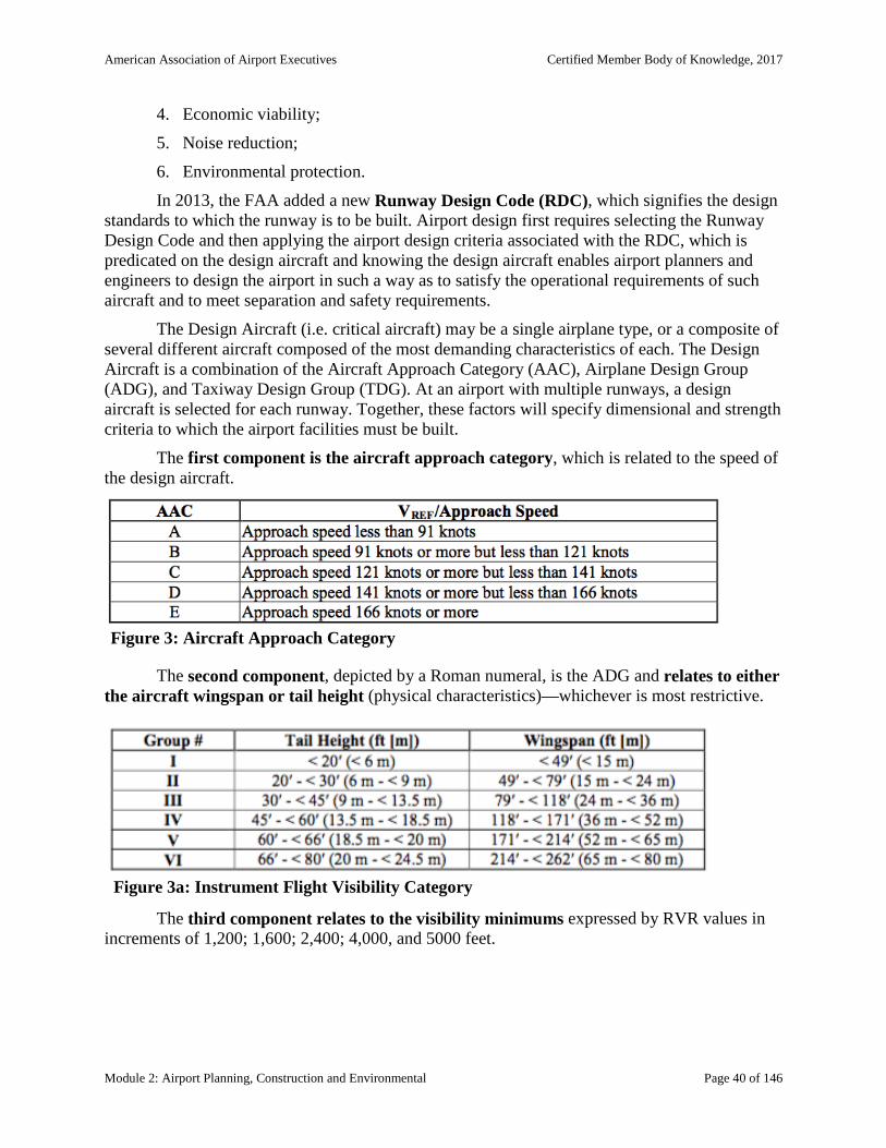
American Association of Airport Executives Certified Member Body of Knowledge, 2017
Module 2: Airport Planning, Construction and Environmental Page 40 of 146
4. Economic viability;
5. Noise reduction;
6. Environmental protection.
In 2013, the FAA added a new Runway Design Code (RDC), which signifies the design standards to which the runway is to be built. Airport design first requires selecting the Runway Design Code and then applying the airport design criteria associated with the RDC, which is predicated on the design aircraft and knowing the design aircraft enables airport planners and engineers to design the airport in such a way as to satisfy the operational requirements of such aircraft and to meet separation and safety requirements.
The Design Aircraft (i.e. critical aircraft) may be a single airplane type, or a composite of several different aircraft composed of the most demanding characteristics of each. The Design Aircraft is a combination of the Aircraft Approach Category (AAC), Airplane Design Group (ADG), and Taxiway Design Group (TDG). At an airport with multiple runways, a design aircraft is selected for each runway. Together, these factors will specify dimensional and strength criteria to which the airport facilities must be built.
The first component is the aircraft approach category, which is related to the speed of the design aircraft.
The second component, depicted by a Roman numeral, is the ADG and relates to either the aircraft wingspan or tail height (physical characteristics)—whichever is most restrictive.
The third component relates to the visibility minimums expressed by RVR values in increments of 1,200; 1,600; 2,400; 4,000, and 5000 feet.
Figure 3: Aircraft Approach Category
Figure 3a: Instrument Flight Visibility Category

American Association of Airport Executives Certified Member Body of Knowledge, 2017
Module 2: Airport Planning, Construction and Environmental Page 41 of 146
The Airport Reference Code (ARC) is a designation that signifies the airport’s highest
Runway Design Code minus the visibility component of the RDC. The ARC is used for planning and design purposes only and does not limit the aircraft that are able to operate safely on the airport.
Occasionally, the FAA makes changes to the airport design standards, which need to be included in an existing ALP. Any new construction at an airport after the effective date of a new design standard requires incorporation of that standard. If, however, an airport has a unique threshold setting or restriction, the FAA can conduct a study to assess the feasibility of modifying the design change. Airport management cannot make or permit any changes to the airport or its facilities that might adversely affect safety, utility, or efficiency. Therefore, any request for modification to a design standard must show that an equivalent level of safety and efficiency will be provided in the alternative design.
Runway Layout
Design considerations for runways include the ARC, meteorological conditions, the surrounding environment, topography, and the volume of air traffic expected. Runway alignment is predicated on attempting to achieve a direction in which the critical aircraft can use the runway within its max crosswind component at least 95 percent of the year. If 95 percent coverage is not obtained, a crosswind runway is recommended.
Runway layouts are also affected by the availability of airspace. Existing or planned instrument approach procedures, missed approach procedures, departure procedures, control zones, special use airspace, restricted airspace, and traffic patterns all influence airport layouts and airspace needs. The FAA includes over 20 different runway layouts in the advisory materials; however, they are all based on four basic runway configurations: (1) single, (2) open-V, (3) parallel, and (4) intersecting.
The single runway is the simplest of the basic configurations. During Visual Flight Rules (VFR) conditions, this one runway should accommodate up to 99 light aircraft operations per hour. While under Instrument Flight Rules (IFR) conditions, it can accommodate between 42 to 53 operations per hour, depending on the mix of traffic and navigational aids available at that airport.
The four types of parallel runways are distinguished by their proximity to one another:
1. Close = less than 2,500 feet between runways
2. Intermediate = 2,500 to 4,300 feet between runways
3. Far Parallel = 4,300 feet or greater between runways
Figure 4: Instrument Flight Visibility Category

American Association of Airport Executives Certified Member Body of Knowledge, 2017
Module 2: Airport Planning, Construction and Environmental Page 42 of 146
4. Dual Lane = 4,300 feet or more apart between each pair
Two runways that diverge at an angle but do not intersect are called open-V runways. When there is no wind, an open-V configuration allows both runways to be used at the same time, significantly increasing the number of operations per hour. When strong winds favor one runway, the other runway may still be operational. When takeoffs and landings are made toward the two closer ends, the number of operations per hour can be reduced by 50 percent. The capacity of open-V runways, while greater than a single runway, is limited by the closeness of the runway ends to each other. The capacity of all configurations involving crosswind runways is affected by wind direction and strength. Strong winds may limit operations to just one runway.
When two or more runways cross, they are classified as intersecting runways. Strong winds will limit operations to just one runway. Light winds may allow both runways to be used. Intersecting runways also require more land area than other types of configurations. The capacity of intersecting runways greatly depends on the location of the intersection and the way the runways are operated.
Runways will normally have a 1 to 1.5 percent cross section grade to ensure water runoff. The runway shoulders will have a 1.5 to 5 percent slope to ensure the same. Runway shoulders are required to be stabilized to prevent erosion from runoff or jet blast. Airports serving large, four-engine jet aircraft will often have paved shoulder areas, whereas smaller airports have grass runway shoulders.

American Association of Airport Executives Certified Member Body of Knowledge, 2017
Module 2: Airport Planning, Construction and Environmental Page 43 of 146

American Association of Airport Executives Certified Member Body of Knowledge, 2017
Module 2: Airport Planning, Construction and Environmental Page 44 of 146
A Runway Threshold is the beginning portion that is available for landing or takeoff. A displaced threshold may be required in three instances: (1) when an object obstructs the airspace needed for landing aircraft, (2) for environmental considerations such as noise abatement, or (3) if necessary to provide standard runway safety area dimensions or runway obstacle free zone lengths. A Displaced Threshold is located some distance down the runway. The portion of the runway leading up to the displaced threshold may still be used for aircraft takeoffs and rollouts when landing in the opposite direction. When a penetration to an approach surface exists (when an obstruction infringes upon the runway approach corridor), the airport operator must take one of three actions: (1) remove or lower the object to acceptable threshold siting requirements, (2) displace the threshold, thereby shortening the landing distance, or (3) ask the FAA to raise the visibility minimums on the runway approach.
Runway and Taxiway Protection Areas
Safe and efficient airport operations require that certain areas on or near the airport are clear of objects or restricted to those objects functionally necessary such as lights and navigational aids. These areas include the Runway Safety Area (RSA), the Runway Protection Zone (RPZ), Object Free Area (OFA), Obstacle Free Zone (OFZ), and Runway Safety Area (RSA). Taxiways also have similar protected areas.
Runway and Taxiway Safety Areas
In the early years of aviation, all aircraft operated from relatively unimproved airfields. As aviation developed, the alignment of takeoff and landing paths centered on a well-defined area known as a landing strip. As aircraft became more advanced, it was necessary to pave the center portion of the strip, which became known as the runway. The term “landing strip” was initially retained28 to describe the graded area surrounding and upon which the runway was constructed, and its primary purpose changed to that of a safety area surrounding the runway. The current RSA standards are based on 90% of overruns being contained within the RSA (FAA, 2014, p. 59). Taxiways also have safety areas as aircraft can occasionally experience ground steering problems or brake failures while taxiing which may result in the aircraft running off the paved taxiway surface. Taxiway safety areas are smaller in dimension than Runway Safety Areas.
A Runway Safety Area (RSA) is a defined area comprising either a runway or a taxiway and the surrounding surfaces, areas that are prepared for, or are suitable for, reducing the risk of damage to airplanes in the event of an undershoot, overshoot, or excursion from the runway or the unintentional departure from a taxiway. This safety area must be maintained so that it is clear of debris, drained, and graded, as it must be able to support aircraft in the event that they depart from the pavement. Safety Areas are also designed to support snow removal, aircraft rescue, and firefighting operations under normal conditions. The safety area includes the runway’s structural pavement, shoulders, blast pad, and stop ways.
28 The term “landing strip” is still used in ICAO definitions of the Runway Safety Area.

American Association of Airport Executives Certified Member Body of Knowledge, 2017
Module 2: Airport Planning, Construction and Environmental Page 45 of 146
Runway Safety Areas have a total width range of 120 to 500 feet, depending on the aircraft design group and the approach to the runway. Taxiway safety areas range from 49 to 262 feet in total width. Airport management is required daily to inspect the safety areas for problems such as rutting, rough and/or uneven terrain, and mounds of dirt, debris, and obstructions not mounted on frangible couplings. Objects located in the Safety Area because of their function (i.e., lights, signs) must be mounted on frangible couplings that have breakaway points no higher than three inches above grade. Runway Safety Areas extend past each of the runway ends to provide a greater safety margin for aircraft that undershoot or overshoot the runway. The dimensions vary based on the category of the runway and whether or not electronic approach aids are associated with the runway. The dimension requirements of a particular runway or taxiway safety area can be found in the FAA’s Airport Design Advisory Circular.
Efforts are being made to reduce the severity of airport accidents and incidents by improving the overrun areas. Newer technology or alternative systems have been developed for those runways that have less than the required Safety Area. Generally, runways that are unable to provide the necessary runway safety areas are located in close proximity to bodies of water, large drop-offs, railroads, or highways. One solution is a soft ground arrester system called an Engineered Material Arresting System (EMAS). EMAS is designed not to deform under normal ground vehicle loads. Two providers are approved by the FAA EMASMAX arrestor beds are composed of blocks of lightweight, crushable cellular cement. Runway Safe EMAS is a foamed silica bed made from recycled glass and contains a high-strength plastic mesh anchored to the pavement at the end of the runway.
Other Protected Areas around the Runway
Runways have a variety of protection areas and zones, in order to provide enough room for aircraft operations and to ensure the safety of those on the ground—particularly those personnel that are operating in the Movement Area. Knowing the restrictions of these protected areas, can assist airport maintenance and operations personnel in understanding how close to an active runway they are allowed to operate, such as conducting mowing operations, airfield maintenance, and other necessary activities.
The Runway Protection Zone (RPZ) is a trapezoidal-shaped area located off the runway ends, designed to enhance the protection of people and property on the ground. It lies under the innermost portion of the runway’s approach surface and is required to be under the control of the airport (through ownership or by easement). The RPZ begins 200 feet from the end of a runway area that is usable for takeoff or landing. The FAA recommends fee simple ownership (i.e., outright acquisition of the property) and complete land use control of the RPZ. It may, however, be impracticable for the airport owner to acquire and plan the land uses within the entire RPZ.
The overall size of the zone varies with the Design Aircraft and approach visibility minimums used for a particular runway. It can vary in length from 1,000 feet to 2,500 feet. The smallest width of the trapezoid is the same as that of the primary surface area. It then widens as it moves from the runway end into the approach area. Clearing all objects from the RPZ is desirable, but some uses are permitted, provided they do not attract wildlife. Some land uses, such as golf courses and agricultural operations are allowed, while others, such as churches, schools, hospitals, shopping centers, and fueling facilities, are expressly prohibited.

American Association of Airport Executives Certified Member Body of Knowledge, 2017
Module 2: Airport Planning, Construction and Environmental Page 46 of 146
The Object-Free Area (OFA) is a ground area based on the runway, taxiway, or taxilane centerline that enhances the safety of aircraft. The OFA must be free of objects, except for those items needed for air navigation or aircraft ground maneuvering (i.e., antennas, lights, signs). The width of the runway OFA varies from 250 feet to 800 feet, and its length varies from 240 to 1,000 feet past the end of the runway or stopway, depending on the ARC. Taxiway and taxilane OFAs also vary in dimensions.
The Obstacle-Free Zone (OFZ) is the airspace above the runway elevation at any point, but below the 150-foot floor of the horizontal surface area under Part 77. Extending 200 feet beyond each runway, its width varies from 120 feet to 400 feet, depending on the visibility requirements and aircraft size. The OFZ is to be kept clear of all objects except for visual aids, mounted on frangible couplings that need to be functionally located in this area. For runways having an approach lighting system or visibility minimums lower than 3/4-statute miles, an inner approach OFZ and inner transitional OFZ exists for each, respectively.
The Building Restriction Line (BRL) is shown on the ALP and identifies suitable building area locations on airports. The assumed building height is usually 35 feet. The BRL is a planning tool; when determining the location of a proposed building, the actual height should be considered.
Declared Distances refer to the distances the airport owner declares available for a turbine-powered aircraft’s takeoff run (on the paved areas), takeoff distance (available unobstructed airspace), accelerate-stop distance (distance the aircraft has to stop in case of an aborted takeoff), and landing distance (available pavement for landing) requirements. The declared distances are: Take-Off Run Available (TORA), Take-Off Distance Available (TODA), Accelerate-stop Distance Available (ASDA), and Landing Distance Available (LDA). Aircraft configuration and performance specify the actual operational limitations of the plane. Pilots can compare the declared distances at a particular airport to assess whether their aircraft meets the performance requirements for safe operation at the airport. The FAA provides declared distances at runways that do not have enough space for an adequate RSA.
To increase safety associated with aircraft using intersecting runways when buildings block visibility of aircraft on other runways, the FAA requires Runway Visibility Zones (RVZ). The RVZ is an area formed by imaginary lines connecting the visibility points of two different runways (i.e. the blind spots). The visibility points for each runway are calculated to allow adequate time for one aircraft to see and avoid an aircraft using the other runway.
Additional Definitions
In addition to OFA, OFZ, RSA, RPZ, and BRL, other parameters in the design and operation of an airport need to be defined. They include:
1. The airport elevation is the highest point on an airport’s usable runway and is expressed in feet above Mean Sea Level (MSL).
2. The Airport Reference Point (ARP) is the latitude and longitude of the geometric center of the airport’s runways.
3. Maximum takeoff weights differ based on designation. A large airplane is certificated for maximum takeoff weights of more than 12,500 pounds while a small

American Association of Airport Executives Certified Member Body of Knowledge, 2017
Module 2: Airport Planning, Construction and Environmental Page 47 of 146
aircraft is certificated for 12,500 pounds or less. Note that these weight limits are different from the one used to determine small and large aircraft for the purpose of wake turbulence separation. Also, the definitions of large and small here, are different than the large and small definitions used in establishing the Class of Part 139 certification (e.g. 10-30 seats equals small, and more than 31 seats equals large).
4. Rectangular in shape, a Stopway is the area beyond the departure end of the runway used to support and minimize damage to an airplane in the event of an overrun.
5. A Clearway is a rectangular area off the departure end of a runway that is suitable for use in calculating aircraft takeoff performance. The clearway is factored into how much takeoff distance is available (TODA), recognizing that an aircraft’s initial climb after rotation may require an obstacle-free area beyond the runway departure end.
Taxiway and Apron Design
Taxiway Design
A taxiway is a defined path located in the Movement Area and is used for aircraft to move from one point of an airport to another. Taxiway turns and intersections are designed to enable safe and efficient taxiing by airplanes while minimizing excess pavement. Unlike the RDC, which is based on the approach speed, and wingspan or tail height, planners use the Taxiway Design Group (TDG) to guide the design of taxiways. The TDG guidance is based on several factors including the aircraft width, the dimensions of the undercarriage including the overall Main Gear Width (MGW) and the Cockpit to Main Gear Distance (CMG), and runway to taxiway and taxiway/taxilane separation requirements. These parameters also affect the design of pavement fillets. For certain aircraft that have steerable main gear, planners should use the “effective CMG,” which is a data point provided by the aircraft manufacturer (FAA, 2014, p. 115).
Unlike runways, which are designed to accommodate a particular type of aircraft, taxiway design is driven by the type of aircraft most likely to use the taxiway. As an aircraft negotiates through turns on taxiways that are designed for cockpit over centerline taxiing, the main gear requires additional pavement in the form of fillets to maintain the Taxiway Edge Safety Margin (TESM). Taxiways also have protected areas such as Safety Areas and object-free areas. Taxiways should be designed such that the nose gear steering angle is no more than 50 degrees, the generally accepted value to prevent excessive tire scrubbing (FAA, 2014, p. 115).
Taxiway widths typically vary from 25 to 100 feet, while the taxiway safety area correspondingly varies from 49 to 262 feet. A taxilane is a portion of a ramp used for access between taxiways and aircraft parking positions. While the design standards remain the same for taxilanes, they are not typically a part of the Movement Area.
The design principles associated with taxiway systems are to do the following:
1. Avoid wide expanses of pavement;
2. Provide a bypass capability or multiple accesses to the runway;
3. Minimize runway crossings and provision of ample turning radii;
4. Provide visibility of taxiing aircraft; and

American Association of Airport Executives Certified Member Body of Knowledge, 2017
Module 2: Airport Planning, Construction and Environmental Page 48 of 146
5. Prevent ingress and egress bottlenecks.
Good airport design practices reduce the number of taxiways intersecting at a single location by keeping taxiway intersections simple. This approach allows for better placement of airfield markings, signage, and lighting. Taxiway intersections that are too complex increase pilot and airfield driver errors. Planners are encouraged to follow the three-node concept, meaning that a pilot should be presented with no more than three choices at an intersection—ideally, left, right, and straight ahead (FAA, 2014, p. 115).
The FAA encourages that taxiway turns be 90 degrees whenever possible as these intersections provide the best visibility to the left and right for a pilot. To increase runway efficiency (i.e. move the planes on and off faster) many airport planners also include acute angle taxiways for high-speed turnoffs, but these turnoffs should not be used as a runway entrance or crossing point (FAA, 2014, p. 115). A high-speed taxiway turnoff considers factors such as the type of aircraft using the runway, the frequency of use, and the effect of weather conditions on the pavement surface. Wet or dry conditions will have an effect on the ability of an aircraft to slow down in time to make the turnoff. The placement of exit taxiways is crucial. Taxiways that connect to the runway at right angles force the aircraft to slow to almost a complete stop before turning, thereby increasing runway occupancy time—a contributing factor of airfield delay and a capacity constraint.
FAA design guidance asks planners to avoid dual-purpose pavements, which are runways that can be used as taxiways, and indirect access, in which there is a taxiway that leads straight to the runway from the ramp without a turn. A straight-line taxiway from ramp to runway can increase runway incursions by both pilots and vehicle operators (FAA, 2014, p. 115).
To mitigate the closing or rerouting of surface transportation facilities, taxiway and runway bridges have been constructed at a number of U.S. airports. Taxiway separations, is the required distance between a taxiway/taxilane centerline and other objects is based on the required wingtip clearance, which is a function of the wingspan, and is thus determined by ADG. The need for ample wingtip clearance is driven by the fact that the pilots of most modern jets cannot see their aircraft’s wingtips. The required distance between a taxiway/taxilane centerline and another taxiway/taxilane centerline, however, may be a function of the TDG because of turning requirements.
Apron (Ramp, Tarmac) Design
Aircraft park on aprons (i.e. tarmacs or ramps; these three terms are used interchangeably in the industry), therefore, apron design should accommodate the loading and unloading of passengers, cargo, baggage, and other activities such as fueling, maintenance, and ground vehicle circulation needs. Aprons are usually in the Non-Movement Area of the airport. Apron design should also take into consideration the prevention of runway incursions. Direct connection from an apron to a parallel taxiway at the end of a runway is not recommended, as this geometry contributes to runway incursions. Apron location should take into account the effects of jet blast and allow for sufficient area for safe maneuvering of aircraft and ground vehicles (FAA, 2014, p. 166).
There are three basic types of aprons: terminal (passenger and cargo), remote, and hangar. Passenger terminal aprons are where passengers board and deplane from an aircraft.

American Association of Airport Executives Certified Member Body of Knowledge, 2017
Module 2: Airport Planning, Construction and Environmental Page 49 of 146
Apron design must typically accommodate multiple activities such as fueling, maintenance, catering, loading/unloading baggage and cargo, aircraft servicing, boarding bridge maneuvering, passenger boarding/deplaning, and aircraft docking/pushback. Cargo aprons are dedicated to cargo flight operations and must accommodate mail and freight type loading and unloading operations (FAA, 2014, p. 165).
Remote aprons are located in an area where aircraft can be secured and stored for long periods of time. These are located remotely from either terminal or hangar aprons and often accommodate Remain-Over-Night (RON) airline or corporate traffic or provide tie-down areas for smaller aircraft. Hangar aprons is the surface in front of an aircraft hangar that accommodates aircraft movement, into and out of the hangar.
Apron design should be appropriate to the type of aircraft operation being conducted. For a commercial airline passenger aircraft, aprons should accommodate room for the operation of the passenger boarding bridges, while the apron on a GA ramp may have to accommodate a certain amount of vehicle traffic as passengers are picked up or dropped off by way of a limo or personal vehicle. A determination of the total amount of apron area needed cannot be developed by formula or empirical relationship since local conditions often vary significantly from one airport to another. Critical characteristics of apron design include: capacity, layout, efficiency, flexibility, safety, and hangar locations (FAA, 2014, p.166)
The four primary considerations that govern efficient apron area design are: (1) the movement and physical characteristics of the aircraft to be served; (2) the maneuvering, staging, and location of ground service equipment and underground utilities; (3) the dimensional relationships of parked aircraft to the terminal building; and (4) the safety, security, and operational practices related to apron control. The primary objective of these considerations is the readily accommodated airport’s aircraft mix. It is customary to use the peak hour volume to estimate the number of gates required at the airport, but this practice must be balanced with the capacity of the runways.29 The type of terminal (simple, linear, pier, or satellite) will also affect apron design. The primary design consideration is to provide adequate wingtip clearances for the aircraft positions and the associated taxilanes. Parked aircraft must remain clear of the Object Free Areas (OFAs) of runways and taxiways and no part of the parked aircraft should penetrate the runway approach and departure protected surfaces (FAA, 2014, P. 167).
The gate occupancy time is the amount of time an airplane occupies the gate. Large aircraft normally have longer occupancy times due to the more extensive aircraft servicing, preflight planning, and refueling.30 Gate times can be as low as 20 to 30 minutes for smaller or regional aircraft, and from 40 minutes to over an hour for a larger international aircraft.31 On average, a gate is used 50 to 80 percent of the time. This number moves up slightly when gates are commonly used from 60 to 80 percent of the time. Exclusive-use gates drop turnaround time to 50 or 60 percent per hour.
29 Graham, A. (2008). (3rd ed.). Burlington, MA: Butterworth-Heinemann. 30 Oldham, J. (2007). “Environmental Management.” In L. E. Gesell and R. R. Sobotta (Eds.).The Administration of Public Airports. Chandler, AZ: Coast Aire Publications.(pp. 275-322). 31 Ibid

American Association of Airport Executives Certified Member Body of Knowledge, 2017
Module 2: Airport Planning, Construction and Environmental Page 50 of 146
Stand Guidance Systems
Aircraft manufacturers publish manuals detailing the characteristics of each airframe in their fleet. This provides information on turning radii, loading bridge door heights, wing tip clearances, servicing ports, and the location of stand guidance systems. A variety of stand guidance systems exist, including Aircraft Positioning and Information Systems, Safegate, and Safedock. Stand guidance systems are visual aids located on the side of a terminal building, so as to be viewed from the pilot’s perspective as they approach the aircraft parking location. The visual indicators tell the pilot whether they are on the centerline of the parking position and when to stop.
The optimum apron design for a specific airport will depend on available space, aircraft mix, and terminal configuration. Other considerations in apron and ramp design require an assessment of aircraft access, handling and use requirements, protection from jet and propeller blasts, hydrant or other fueling or servicing needs, and emergency access for ARFF vehicles and personnel. In some cases and at smaller airports, passengers may be required to walk from the terminal building directly to the aircraft, so adequate safety measures need to be considered to ensure passengers do not walk in an area of aircraft movement and are suitably protected from moving props or jet blast.
Aircraft Fueling Operations related to Apron Design
Fueling operations at small, GA airports will usually consist of a fuel pump facility.
Fueling from a stationary pump facility tends to be more economical than fueling from trucks, a method that is more common at larger airports. At major air carrier airports, underground fuel hydrant systems adjacent to the terminal are safer, more economical, and more efficient when compared with the airline’s direct and indirect costs in having numerous vehicles in and around aircraft. In the design of terminal apron areas, the terminal gate type helps to establish the minimums for the required space. The wingspans and fuselage lengths of the aircraft using the terminal building are used to define the type of gate.
Design of Other Landing Facilities
The FAA’s definition of an airport includes heliports, vertiports, glider ports, seaplane bases, ultralight flight parks, manned balloon-launching facilities, and possibly soon, droneports. A landing and takeoff area is defined as any area of land, water, or structure used, or intended to be used, for the landing and taking off of aircraft.
Heliports
Helicopters provide a unique capability to communities when they are integrated into the local transportation system. In addition to their general service in the transportation of people, helicopters have proven to be useful for disaster relief, air ambulance services, police departments, news reporting, construction, and handling of high-value cargo. Companies use helicopters as an invaluable part of an in-house transportation system to connect the main office with various plants, job sites, and the local airport. Utility companies use helicopters to construct and inspect high-voltage electrical lines and to monitor underground gas transmission lines.

American Association of Airport Executives Certified Member Body of Knowledge, 2017
Module 2: Airport Planning, Construction and Environmental Page 51 of 146
Newspapers and radio/TV stations use helicopters32 to gather news on site, to take photographs, and to report rush hour traffic conditions. The oil and gas industry is a significant user of helicopter operations, shuttling workers to and from remote drilling locations, including offshore rigs.
Because of the unique operating capabilities of vertical takeoff, landing, and hovering, heliport-landing areas are not restricted to the local airport. Multiple sites within a community can support helicopter operations. The FAA has determined that certificating heliports is not in the public interest and has exempted operators of heliports from complying with Part 139 requirements; therefore, commercial passenger helicopter operations can be conducted from a GA airport.
There are four basic types of heliport designs: general aviation, transport, hospital, and helipads on airports. A GA heliport accommodates helicopters used by individuals, corporations, and helicopter air taxi services. A transport heliport is intended to accommodate air carrier operators providing scheduled service or unscheduled service with large helicopters (FAA, 2012, p. 65). A hospital heliport is limited to serving helicopters engaged in air ambulance, or other hospital related functions. A designated helicopter landing area located at a hospital or medical facility is a heliport and not a medical emergency site33 (FAA, 2014, p. 4).
Similar to the Design Aircraft in airport runway design, heliport design guidance is based on the Design Helicopter, which reflects the maximum weight, maximum contact load/minimum contact area, overall length, rotor diameter, and other factors of the helicopters expected to operate out of the heliport. Two hazards specific to helicopter operations are turbulence and electromagnetic effects. Air flowing around and over buildings, stands of trees, terrain irregularities, etc. can create turbulence on ground-level and roof-top heliports that may affect helicopter operations; nearby electromagnetic devices, such as a large ventilator motor, elevator motor or other large electrical consumer may cause temporary aberrations in the helicopter magnetic compass and interfere with other onboard navigational equipment (FAA, 2012, p. 65). Aircraft systems can also be affected when near these facilities, but aircraft runways are located farther away from the buildings, whereas helicopter flight operations are occasionally conducted much closer.
Other key heliport design considerations include the Touchdown and Lift-Off Area (TLOF) and the Final Approach and Takeoff Area (FATO). The TLOF is a load bearing, typically paved area, centered in the FATO, on which the helicopter lands or takes off. The FATO is a defined area over which the final phase of the approach to a hover or a landing is completed and from which a takeoff is initiated. Like runways, heliports have safety areas located around the FATO and include imaginary surfaces. Imaginary planes are centered about the FATO and the approach/departure paths, which are used to identify the objects where notice to and evaluation by the FAA is required (FAA, 2012, p. 4). Heliports should also have protection zones, which begin at the FATO perimeter and extend out for a distance of 400 feet, upon which the heliport or helipad operator should own or control the property. Heliport design guidance is found in Advisory Circular (AC) 150/5390-2C, Heliport Design.
32 Some news agencies are beginning to switch to UAVs to conduct this type of surveillance. 33 A medical emergency site is an unprepared site at or near the scene of an accident or similar medical emergency on which a helicopter may land to pick up a patient in order to provide emergency medical transport.
American Association of Airport Executives Certified Member Body of Knowledge, 2017
Module 2: Airport Planning, Construction and Environmental Page 52 of 146
Helicopter facilities on Airports (Helipads)
Helicopters are generally able to operate at airports without unduly interfering with airplane operations, but some design considerations should be taken into account. Helicopter passengers often require convenient access to the terminal and ground transportation facilities. At airports with interconnecting helicopter-to-airplane or airplane-to-helicopter passenger traffic, the terminal apron should provide gates for helicopter boarding and appropriate ramp safety measures to reduce hazards created by tail rotors and rotor wash. For GA helicopter operations, the airport should have at least two approach/departure paths meeting the criteria for commercial transport helicopters, which, among other requirements, must be aligned with the predominate wind. Curved VFR approach/departure paths may also be allowed to avoid objects or noise sensitive areas.
The Safety Area, Protection Zone, and FATO dimensions should be applied as they relate to stand-alone heliport facilities. Additional helicopter marking, securities, lighting of obstructions, and ARFF issues should be addressed when an airport begins helipad operations, and the airport operator may wish to install helicopter specific visual glideslope aids. Reference FAA AC 150/5345-52, Generic Visual Glideslope Indicators (GVGI), AC 150/5345-28, Precision Approach Path Indicator (PAPI) Systems, for additional guidance.
Seaplane Bases
A Seaplane Base is an area of water that is used, or is intended to be used, for the landing and takeoff of aircraft, together with associated buildings and facilities on shore. There are two main types of seaplanes: flying boats (often called hull seaplanes) and floatplanes. Floatplanes (i.e. seaplanes) typically are conventional land airplanes that have been fitted with separate floats (sometimes called pontoons) in place of their wheels. The fuselage of a floatplane is supported well above the water’s surface. With a flying boat, the bottom of a flying boat’s fuselage is its main landing gear. This is usually supplemented with smaller floats near the wingtips, called wing or tip floats. A sub-category of flying boats is Amphibians, which are flying boats and floatplanes equipped with retractable wheels for landing on dry land. A key distinction between land airplanes and seaplanes relates to the fact that seaplanes have no brakes and are constantly floating freely in the water. This design requires additional turning and maneuvering room within seaplane bases. Additionally, seaplanes are subject to weathervaning, which is the tendency of the aircraft to yaw with the prevailing wind. While this tendency exists in all airplanes, it is particularly challenging on the water (FAA, 2013a, p. 11-2).
A sea-lane is the defined path, which is prescribed for the landing and takeoff run of aircraft. Lakes, rivers, and harbors offer natural aircraft landing and takeoff areas where the waves are more conducive to aircraft operations. Landing and takeoff areas are best located where the water current flow is less than 3.5 miles per hour, and the wave heights are not classified as swells. On aeronautical charts, a seaplane base is designated by an anchor symbol.
Various governmental bodies control waterways, and rules and regulations vary throughout the United States. Bodies of inland water that are used in commerce are under the purview of the U.S. Army Corps of Engineers, which is responsible for maintaining and regulating the use of navigable waterways. Activities and fixed facilities requiring Corps of Engineer permits include dredging, filling, breakwaters, boat ramps, piers, bulkheads, and riprap.

American Association of Airport Executives Certified Member Body of Knowledge, 2017
Module 2: Airport Planning, Construction and Environmental Page 53 of 146
The U.S. Coast Guard is charged with marking and lighting navigable waterways. This designation means that any markers used to identify a sea-lane require a permit from the Coast Guard. All other bodies or rivers of water not considered navigable waterways will generally fall under the governing authority of the state in which they are located.
Many of the FAA requirements for establishing, decommissioning, and modifying seaplane bases are the same as for land airports. Part 77, Safe, Efficient Use and Preservation of the Navigable Airspace applies. All seaplane base development that is financed with federal funds requires an FAA-approved Seaplane Base Layout Plan (SBLP), which is similar in scope to the land-based ALP.
Droneport/UAVPort Design
Although the FAA has not yet introduced design standards for drone ports or UAV ports, nor have those terms been clearly defined, it has not stopped numerous private UAV operators, and the U.S. Army from establishing such criteria. In 2014, the U.S. Army announced that it would build a special airport for the Grey Eagle and Shadow UAVs at the Fort Bliss Army base in El Paso, Texas. The drone airport will have two runways, a 5,000-foot paved runway, and a smaller 1,000-foot paved runway, and a 50,000-square-foot hangar with office and support buildings, a command and control center, a hot loading facility for munitions, and a hazardous materials building. The drone airport will have a 1,000-foot cleared and graded, dirt, safety, run-out zone at each end of the 5,000-foot runway (i.e., Safety Area), with security lighting and fencing around the perimeter (Keller, 2014). A private company in Boulder City, Nevada is seeking some sort of approval for a 50-acre droneport it is currently operating.
According to the USAF planning criteria for UAV operations, the size and length of the runway depends on the size and flight characteristics of the UAV that will use the facility—i.e., the “Design UAV.” Wingspan, wheel base, weight, landing speed, takeoff distance, turning radii, and recovery method are all taken into account (Keller, 2014).
Other Landing Facilities or Airport Uses
Ultralight Flight Park and hang glider design is addressed under FAA A/C 103-6 (dated June 1983). Development of Criteria for Parachute Landing Areas on Airports is addressed in A/C 150/5300-13A Change 1 Airport Design.
Like Droneport/UAV port design, spaceport design, particularly the horizontal to low-earth-orbit, and return type of spaceport (as opposed to a vertical rocket launch facility) is additional new territory for the aviation industry. Some spaceport design considerations can be found in the text Practical Airport Operations, Safety, and Emergency Management (Price, J., Forrest, J., 2016).
Airport Construction
At most airports in the U.S., construction is a predominant activity, as airports build, tear down and rebuild in a continuing effort to maintain the airport in a safe and serviceable condition and to meet the demand of its aviation customers. While general contractors and subcontractors managed by an airport engineering firm do most of the construction, airport operators benefit

American Association of Airport Executives Certified Member Body of Knowledge, 2017
Module 2: Airport Planning, Construction and Environmental Page 54 of 146
from having a general knowledge of those areas of airport construction that affect the operation of the airport.
Typical construction work items include: land acquisition, site preparation, construction, repair of runways, taxiways, aprons, and airport access roads, installation of airport lighting systems, utilities, navigational aids, weather reporting equipment, safety and security equipment required by regulation, snow removal equipment and buildings, terminal development, equipment to measure runway surface friction, hangar construction, parking garages or lots, art objects, or decorative landscaping.
In a few cases, the airport conducts all phases of planning, expansion, and construction by using only internal expertise. For the majority of airport development programs, however, airport management will seek advice and services from a plethora of entities that offer consulting services. These service providers include architects, certified engineers, environmental experts, interior decorators, and many types of contractors and permit specialists (to name just a few). The time and resources spent by airport management recruiting the appropriate services can be extensive. Tasks include: (a) determining needs, (b) advertising, (c) issuing requests for proposals (RFPs), (d) selection processes, and (e) determining contractual requirements. It is recommended that the airport executive begin by seeking advice from domain-specific industry professional associations. These organizations offer advice on credentials, ethical standards, and selecting related consultants and service providers.
Once architectural, engineering, and other service providers have been selected (or at least screened through the RFP stage), the airport operator can begin to focus on planning the top-level scheduling for construction phases. These phases include: (a) pre-design, (b) design, (c) preconstruction, (d) construction, and (e) inspection phases. It is important to realize that these phases are often iterative, complex, and require extensive consulting by government, legal, and industry experts.
Preconstruction Meetings
After the selection of an engineering consultant, the first phase of the construction project is the Predesign Conference. A Predesign Conference, conducted by the Airport Sponsor or their authorized agent (i.e. engineering firm), is used to discuss critical design parameters, airport safety during construction, phasing of construction operations, and environmental considerations. Possible conflicts between construction activities and the operation of the airport should be resolved at this meeting. Airport tenants directly affected may also be involved in this conference. The predesign conference should be held when preliminary design work is completed and prior to the preparation of the final plans.
For large projects, projects with unique features, or as required to meet local procurement requirements the next step is likely the Pre-bid Conference. Airport Sponsor and their engineer will explain contract requirements for construction methods and procedures, construction safety and phasing requirements, and the procurement process including Disadvantage Business Enterprise (DBE), bonding, subcontracting, and labor. The notice to bidders for the pre-bid conference should be made in accordance with local procurement requirements.

American Association of Airport Executives Certified Member Body of Knowledge, 2017
Module 2: Airport Planning, Construction and Environmental Page 55 of 146
The Preconstruction Conference is conducted by the Airport Sponsor or their authorized agent, to thoroughly discuss critical project issues such as contract requirements, operational safety, construction phasing and sequencing, airport security, quality control, quality acceptance testing, labor requirements, EEO obligations, DBE requirements and other pertinent project matters. The engineer must tailor the agenda for each conference to address the unique and/or complex issues specific to their project. The conference should be attended by all parties affected by the construction in order to gain a better understanding of any potential problems and proactively identify solutions. FAA Advisory Circular 150/5300-9A, Predesign, Pre-bid, and Preconstruction Conferences for Airport Grant Projects, provides guidance on the construction management phase.
Management During Construction
During construction, the airport’s engineering firm usually oversees the management of
the contractors and the construction work. Certain events may occur that require the contractor to perform other work related to the project. These events are often handled with change orders. A change order is a written order (including email) by the Airport Sponsor that is within the right of the sponsor to make a change in the design, drawings, or specifications within the general scope of the contract. Wage rates remain unchanged for the handling of a change order; however, any change that exceeds an increase or decrease of 25 percent of the estimated cost of the contract is a major item, as defined in the contract specifications, and must be accomplished by supplemental agreement.
A supplemental agreement covers work that is not within the general scope of the existing contract or is work that exceeds the 25 percent of the cost of the contract. A supplemental agreement is a separate contract and requires execution by both parties with the same formality as any other contract. A new wage rate decision may be required for each supplemental agreement, unless it involves work under a project for which a wage determination decision was issued, and such a decision has not expired at the time of the award of the supplemental agreement. Extension of contract time as a result of the supplemental agreement must be justified and specified as a part of the supplemental agreement. The FAA does not normally sign off on change orders; however, a list of change orders should be sent to the FAA project manager and discussed whenever a grant amendment is required or eligibility of the work is in question.
Operational Safety During Construction
Prior to construction, the airport executive must have a construction safety plan in order
to ensure safe operational practices during flight operations and for the duration of the project. Airport operators can look for guidance in AC150/5370-2C, Operational Safety on Airports During Construction.
Hazardous practices and marginal conditions created by construction activities can jeopardize operational safety on airports. To minimize disruptions and avoid safety issues, the airport operator has the overall responsibility to plan, schedule, and coordinate construction activities.

American Association of Airport Executives Certified Member Body of Knowledge, 2017
Module 2: Airport Planning, Construction and Environmental Page 56 of 146
The airport operator must take several steps to ensure the safety of a construction project, including:
1. Developing or approving a safety plan;
2. Requiring contractors to submit plans showing how they intend to comply with the safety requirements;
3. Meeting with all entities involved in the project, including airport operations and maintenance personnel that may be overseeing the actual safety procedures during construction, contractors, and tenants (if applicable);
4. Ensuring accurate contact information for all entities, particularly after-hours points of contact for contractors;
5. Holding weekly or, if necessary, daily meetings to coordinate construction activities;
6. Notifying users, particularly ARFF personnel, of construction activities that may affect response routes; issue NOTAMs as appropriate;
7. Ensuring that construction personnel know of any changes in procedures, such as flight or vehicle ground operation, bad weather, or low visibility, that may affect their work;
8. Ensuring that contractors are trained in the determined safety plan, which may include airfield driver training, security processes interaction with ATC, airport signs, marking and lighting, vehicle operation, and communication;
9. Conducting frequent inspections to ensure contractor compliance with established rules and regulations and the safety plan.
Contractors and tenants performing construction also have safety responsibilities which include providing plans for safety compliance, providing a safety officer and point of contact, and restricting the movement of construction vehicles through flagging, barricades, temporary fencing, and escorts. The safety plan should focus on procedures for protecting runway and taxiway safety areas including Object Free Areas and Obstacle Free Zones, and threshold siting criteria. This protection should extend to navigational aids and emergency notification procedures.
At any time during construction, aircraft operations, weather, security, or local airport rules may dictate more stringent safety measures. The airport operator should ensure that both general and specific safety requirements are coordinated with tenants and ATCT personnel. The airport operator should also include these parties in the coordination of all bid documents, construction plans, and specifications on airport construction projects. General safety provisions are contained in AC 150/5370‑ 10, Standards for Specifying Construction of Airports, paragraphs 40‑ 05, “Maintenance of Traffic”; 70‑ 08, “Barricades, Warning Signs, and Hazard Markings;” and 80‑ 04, “Limitation of Operations.”
Particular focus should be given to airport security requirements such as access control and credentialing (for airports under Part 1542) and vehicle movement and operation. A comprehensive vehicle plan should include marking construction vehicles, ensuring vehicle operator training, escort requirements, marking and procedures for access routes and haul roads, radio communications, and procedures to address violations of the safety plan, including traffic

American Association of Airport Executives Certified Member Body of Knowledge, 2017
Module 2: Airport Planning, Construction and Environmental Page 57 of 146
infractions. From a safety perspective, excavations must be prominently marked and, when appropriate, lighted. Open trenches or excavations are not permitted within 200 feet of the runway centerline or within the Runway Safety Area, unless appropriately covered, displaced thresholds and hazards, including closed portions of a taxiway or runway, must be appropriately marked, lighted, and a NOTAM is issued, and construction material should be carefully monitored to ensure stockpiles are not within OFAs or OFZs, and are secured from the wind. Aviation safety is the primary consideration during construction on airports. Many hazardous practices can be mitigated with effective communication and the development of an enforceable safety plan. FAA A/C 150-5370-2e offers a list of hazards to watch for during construction on airfields.
Post-Construction
After construction, the ALP must be updated, as it is a requirement for issuance of grants for future airport development, and all certificated airports must have an up-to-date signing plan, approved by the FAA. The final “as constructed” (sometimes referred to as the “as-built”) plans depict the final construction. Revisions to the original plans are those made necessary by any design and field changes as a result of change orders, supplemental agreements, and other major changes made by the engineer or Airport Sponsor. One copy of the “as constructed” plans must be submitted to the FAA at project closeout. The FAA Airport Data Record (5010 Form) should also be updated after the project is complete.
When an approved construction or alteration is completed, an FAA Form 7460-2 Notice of Actual Construction or Alteration is required to be filed. Another form, FAA Form 7480-1, is filed whenever an airport is to be constructed, activated, or deactivated. For installing NAVAIDS, FAA Order 6030.1 FAA Policy on Facility Relocations Occasioned by Airport Improvements or Changes, provides guidance on eligible costs and design considerations. For non-federally funded NAVAID installations, FAR Part 171 Non-Federal Navigation Facilities provides similar guidance.
For projects that are not part of the approved Airport Layout Plan, particularly projects that are not being carried out by the airport operator but that may cause a hazard to air navigation, a Form 7460 Notice of Proposed Construction, Alteration, Activation and Deactivation of Airports is required to be filed with the FAA.
Imaginary Surfaces
Safe, Efficient Use and Preservation of the Navigable Airspace
As an airport plans for various construction, improvements, or expansions, the airport operator must consider the environmental impact of infrastructure on the ability of aircraft to operate in the airport’s airspace. FAR Part 7734 Safe, Efficient Use and Preservation of the Navigable Airspace provides the airport operator with detailed regulations relating to managing objects that may interfere with aircraft flying in the airport area.
34 Formerly known as Objects Affecting Navigable Airspace.

American Association of Airport Executives Certified Member Body of Knowledge, 2017
Module 2: Airport Planning, Construction and Environmental Page 58 of 146
In general, FAR Part 77 includes the following areas:
1. Establishes standards for determining obstructions in navigable airspace;
2. Sets forth the requirements for notice to the Administrator of certain proposed construction or alteration;
3. Provides for aeronautical studies of obstructions to air navigation to determine their effect on the safe and efficient use of airspace;
4. Provides for public hearings on the hazardous effect of proposed construction or alteration on air navigation; and
5. Provides for establishing antenna farm areas.
In order to provide for safe flight and transition of aircraft from takeoff to landing, federal regulations have been promulgated to help protect the airspace and instrument approaches to airports from the construction of towers, buildings, and other objects that would interfere with the utilization of the airspace. Part 77 of the Federal Aviation Regulations establishes procedures for reporting to the FAA proposed construction that may constitute potential obstructions or hazards to safe air navigation. Determining criteria are found in the regulations, which identify height notification requirements with reduced maximum allowable object heights closer to the airport. Additionally, federal Grant Assurances require Airport Sponsors to take necessary action to protect the terminal area airspace from the hazards to safe flight.
An object is defined under the regulations as any natural growth, terrain, permanent or temporary construction or alteration (including equipment or materials used), and apparatus of a permanent or temporary character. This definition includes items such as trees, construction cranes, well drilling equipment, stockpiled material or earth, buildings, and parked vehicles.
When the FAA develops an approach for a particular runway at an airport, it builds in safety margins to allow for pilot deviations, instrument errors, and terrain or obstacle conditions. Example: if the terrain prevents an approach from meeting that criterion, then a displaced threshold is established to maintain the standard. If a displaced threshold results in too short of a runway for the intended aircraft operation, then the normal decision height of 200 feet for a Category-I ILS can be raised to a height that will allow the aircraft to use the full runway while also maintaining obstruction clearance.
The impact of raising the decision height affects the number of successful approaches and landings made due to weather conditions at the airport. The principal imaginary surfaces defined in FAR Part 77 are shown in Figure 6.
They are identified as the primary surface, transitional surfaces, approach surfaces, the horizontal surface, and conical surfaces.
• The primary surface area is centered on the runway centerline and extends 200 feet past the runway end. Its width varies from 250 feet to 1,000 feet, depending on the type of approach leading to the runway.
• The transitional surfaces extend outward and upward at right angles to the runway centerline and the runway centerline extended at a slope of 7:f1 from the sides of the primary surface and from the sides of the approach surfaces. Transitional surfaces for those portions of the precision approach surface which project through and beyond

American Association of Airport Executives Certified Member Body of Knowledge, 2017
Module 2: Airport Planning, Construction and Environmental Page 59 of 146
the limits of the conical surface, extend a distance of 5,000 feet measured horizontally from the edge of the approach surface and at right angles to the runway centerline.
• The approach surfaces start 200 feet from the runway end and extend outward from the primary surface for a distance of up to 50,000 feet in the case of precision instrument runways (lesser distances for Non-Precision and Visual approach runways). The approach slope can vary 20:1 for a visual runway; 40:1 for a non-precision runway; or 50:1 for a precision instrument runway.
• The horizontal surface area of Part 77 is a level plane 150 feet above the runway elevation. Its surface area is determined by connecting tangents of radii extended from the ends of all the runways. The length of the radii is dependent upon the approach category (i.e. approach speed) for the runway. It is intended to accommodate for the safe operation and maneuvering of aircraft that are performing circle-to-land or missed approaches. The horizontal surface extends outward for a distance of 5,000 feet for a visual approach runway, and 10,000 feet for an instrument approach runway.
• The conical surface starts at the perimeter of the horizontal surface and continues upward at a slope of 20:1 for a horizontal distance of 4,000 feet.
Figure 6: Part 77 Obstacle Surfaces
FAR Part 77 defines an obstruction and the requirements to file for notification under Part 77 as §77.13. Any person or organization intending to sponsor any of the following construction or alterations must notify the Administrator of the FAA:
1. Any construction or alteration exceeding 200 feet above ground level;
2. Any construction or alteration:
a. Within 20,000 feet of a public-use or military airport that exceeds a 100:1 surface from any point on the runway of each airport with at least one runway

American Association of Airport Executives Certified Member Body of Knowledge, 2017
Module 2: Airport Planning, Construction and Environmental Page 60 of 146
more than 3,200 feet in length.
b. Within 10,000 feet of a public-use or military airport that exceeds a 50:1 surface from any point on the runway of each airport with its longest runway no more than 3,200 feet in length
c. Within 5,000 feet of a public-use heliport that exceeds a 25:1 surface.
3. Any highway, railroad, or other traverse way that has a prescribed, adjusted height that would exceed the above noted standards:
4. When requested by the FAA; and
5. Any construction or alteration located on a public-use airport or heliport regardless of height or location.
Notification to the FAA by the airport operator (or other entity intending to do construction) is carried out through a FAA Form 7460-1 Notice of Proposed Construction or Alteration, which can be completed online. Upon receipt of proposed construction, the FAA conducts a Part 77 study by analyzing the effect the construction would have on the access to an airport and the safe operation of aircraft. As a result of the study, the FAA may resist, oppose, or recommend against the presence of objects or activities that would conflict with an airport design planning standard or planning recommendation.
FAR Part 77 addresses the notification, evaluation, and determination processes for notifying the FAA of any proposed alteration or construction. An FAA determination is a conclusion based on a study of a structure’s projected impact on the safe and efficient use of the navigable airspace. The regulations do not provide the FAA with the authority to prevent construction or alteration to a structure. This level of authority is reserved for the local, regional, or municipal zoning authorities. For this reason, the FAA insists upon land use planning in and around airports to promote compatible uses and also to protect the FAA’s investment in the airports and the airways.
Upon completion of an Aeronautical Study, the FAA will issue a determination stating whether the proposed construction or alteration would be a hazard to air navigation. The FAA will issue a Determination of Hazard to Air Navigation when the Aeronautical Study concludes that the proposed construction or alteration will exceed an obstruction standard and would have a substantial aeronautical impact. The FAA will issue a Determination of No Hazard to Air Navigation when a proposed structure does not exceed any of the obstruction standards and would not be a hazard to air navigation. However, in some cases, the FAA may issue A Determination of No Hazard to Air Navigation, but conclude that the proposed construction or alteration will exceed an obstruction standard yet would not have a substantial aeronautical impact to air navigation. In this circumstance, the FAA may issue conditional provisions of a determination, such as limitations necessary to minimize potential problems like the use of temporary construction equipment, supplemental notice requirements, and marking and lighting recommendations.
The FAA requires notification under this Part, regardless of whether the modification is permanent or temporary. Examples of permanent modifications include buildings, roadways, AWOS/ASOS, and elevated signage. Examples of temporary construction include drilling rigs, stockpiles, cranes, and temporary lights. Temporary and permanent modifications, such as

American Association of Airport Executives Certified Member Body of Knowledge, 2017
Module 2: Airport Planning, Construction and Environmental Page 61 of 146
construction cranes or new buildings, can affect the environmental quality of the airport’s surrounding airspace. FAR Part 77 is designed to allow proactive management of these concerns by the government and the airport’s management.
If an FAA study should determine that the proposed construction or alteration of a structure would interfere in the operation of the air navigation system, the FAA will seek modifications to the application or will change the operational use of the affected airport or airspace. Examples of operational changes are displacing a threshold, raising the approach minimums or visibility requirements, or raising the aircraft minimum descent altitude in the area. Each of these actions may reduce the capacity and operational capability of an airport. Airport management then has the option to accept the restrictions or remove the obstacle. The FAA has several options in mitigating any object that penetrates a runway’s threshold siting requirements or approach slope surface, for example: (1) relocating a threshold, (2) asking the airport operator to remove the object if possible, (3) raising the approach minimums or visibility requirements, and (4) raising the aircraft minimum descent altitude in the area. To ensure notification of all potential objects that may affect flight operations in a particular area, some states and airports have enacted their own legislation requiring notice to be filed with a local zoning office. In turn, the zoning office informs all of the airport, regional, or state offices.

American Association of Airport Executives Certified Member Body of Knowledge, 2017
Module 2: Airport Planning, Construction and Environmental Page 62 of 146
AIRPORT TERMINAL DESIGN Objective 4: Describe the various types of airport terminal design considerations, including terminal layouts and design features. References and Highly Recommended Additional Reading
1. FAA. (1988). Planning and design guidelines for airport terminal facilities (AC 150/5360-13) (FAA). Washington, D.C.: FAA. (NOTE: a revised AC 150/5360-13A Airport Terminal Planning and Design in draft form can be found on the FAA’s website).
2. Landrum & Brown, Hirsh Associates, Kimley-Horn & Associates, Jacobs Consultancy, The S-A-P Group, TransSecure, . . . Presentation & Design Inc. (2010). Airport Passenger Terminal Planning and Design Volume 1 (ACRP Report 25) (TRB/ACRP). Washington, D.C.: ACRP.
3. Landrum & Brown, Hirsh Associates, Kimley-Horn & Associates, Jacobs Consultancy, The S-A-P Group, TransSecure, . . . Presentation & Design Inc. (2010). Airport Passenger Terminal Planning and Design Volume 2 (ACRP Report 25) (TRB/ACRP). Washington, D.C.: ACRP.
Why This Is Important
Terminal design relates directly to the passenger experience, airfield safety, the efficiency with which passenger baggage can be moved, safety and security related issues, and the first (and last) impression many visitors have of the community. Passengers, who have an easier time moving through the airport, tend to spend more money on concessions and thus airports have more favorable rankings in customer service surveys. Since terminal building construction is a significant capital investment that will be with the airport for many years to come a clear understanding of the types of terminals, their advantages and disadvantages to airport, landside, and passenger operations, is necessary for success.
Introduction
A fundamental role of the airport passenger terminal is to transition passengers from ground transportation to air transportation and then back to ground transportation. The terminal is the major interface between the airfield and the rest of the airport, connecting the landside operations to airside operations.35 The terminal includes facilities for passenger and baggage processing, airport maintenance and operational activities, airport and airline administration, and
35 Horonjeff, Robert, Francis X. McKelvey, William J. Sproule, and Seth B. Young. Planning and Design of Airports. 5th ed. New York: McGraw-Hill, 2010. Print. (p. 384).

American Association of Airport Executives Certified Member Body of Knowledge, 2017
Module 2: Airport Planning, Construction and Environmental Page 63 of 146
cargo handling.36
An airport terminal provides for the safe, efficient, and comfortable transfer of passengers and their baggage to and from aircraft and various modes of ground transportation. To accomplish these objectives, essential elements such as ticketing, passenger processing, baggage handling, and security inspection are required. Food service, car rental, shops, restrooms, airport management, and other ancillary functions also support these elements. For GA airports, terminal design provides for a common waiting area supported by service counters, food service, restrooms, pilot services, airport or FBO management, and other ancillary functions.
Air carrier airports must be able to accommodate compressed peak passenger and baggage conditions. Since some airports are located away from urban centers, there may be a greater need for adequate roadway access and parking facilities than at other urban transportation terminals. Airport terminals may not only serve domestic and international scheduled airlines but, in most cases, also accommodate GA activities.
In consideration of these functions, airport planners attempt to provide for terminals that balance the present and future needs for passenger convenience, baggage handling, aircraft operations, ground access, security, blast protection, revenue generation, business commerce, and operational control. An important element of the terminal design is to take into account the overall passenger experience. Passenger experience is addressed in this section from a design perspective and in module 4 from an operational perspective.
Terminal Design Considerations and Concepts
Components of the Terminal System
The passenger terminal system is composed of three elements: the access interface (for activities such as landside operations, intermodal transportation, parking, and vehicle circulation, loading, and unloading,); the passenger processing interface (ticketing, baggage claim, security screening and federal inspection services); the flight interface (conveyances to and from aircraft loading and unloading areas).37
The access interface begins and ends with the intermodal connections to the community that surround the airport. The access interface includes curb frontage for the loading and unloading of passengers, parking facilities, public transit, taxi and limousine services, pedestrian walkways for crossing roads including tunnels, bridges, or automated people moving devices, and service roads and fire lanes that provide access for airport maintenance, vendor deliveries, airfreight, and similar support activities.38
The passenger processing system includes airline ticket counters, baggage claim areas, flight information display screens, concessions, public lobby(s), and food prep areas. The passenger processing interface also includes areas that passengers typically do not see such as space for the interlining of baggage, baggage sorting areas (typically behind the walls of the 36 Ibid 37 Ibid, p. 392 38 Ibid, p. 398

American Association of Airport Executives Certified Member Body of Knowledge, 2017
Module 2: Airport Planning, Construction and Environmental Page 64 of 146
ticket counter or underneath the terminal building), airport administration offices (access control/badging, human resources, airport administration), maintenance areas, and Federal Inspection Facilities. The security-screening checkpoint is also within the passenger processing area of the terminal. Certain non-public areas may also be included such as employee daycare facilities for the children of individuals who work at the airport, vendor storage areas, and physical fitness facilities for employees.
The flight interface includes the concourses and connections to other concourses to accommodate transferring passengers, departure lounge areas where passengers wait to board their flights, passenger-boarding devices such as jet-bridges or air stairs, airline operational and administrative spaces, and, in some cases, non-public areas such as vendor storage spaces that are used to maintain stock for concessionaires.
Terminal Location
Numerous factors are involved in determining terminal design. Terminals must be able to accommodate passenger demands, landside access requirements, and be compatible with airside operations. Terminal design should take into consideration the vision for airport growth (often reflected in the Master Plan) and the ability to meet future demand; terminal design should also be operationally-practical, striving to achieve a smooth flow among landside, terminal, and airfield facilities during the peak hour demand. Environmental facility maintenance and room for future improvements in aviation technology (such as new navigational aid and air traffic control systems) should all be considered.39
In the case of a new or major airport redevelopment, a new site requires a number of basic considerations that can affect the ultimate terminal location.
Some of the more important of these considerations include:
1. Runway Configuration
2. Access to Transportation Network
3. Expansion Potential
4. FAA Geometric Design Standards
5. Existing and Planned Facilities
6. Terrain
7. Environmental Impacts
An airport’s runway configuration has a significant impact on the location of the terminal complex. Many airports are constrained in this regard because their original layout was completed before the introduction of jet aircraft. Accordingly, fiscal constraints and airport improvements have tended to reinforce the existing layouts.
Any terminal development or location strives to balance passenger convenience, operating efficiencies, facility investments, and aesthetics. Passenger convenience is 39 Ibid, p. 392

American Association of Airport Executives Certified Member Body of Knowledge, 2017
Module 2: Airport Planning, Construction and Environmental Page 65 of 146
exemplified by close-in parking, quick curbside checking, adequate queuing and waiting space, short walking distances to aircraft gates, protection from the weather, convenient restroom facilities, available concession services, and easy baggage claim areas. These factors sometimes contrast with the operating efficiency needs of the airlines and the airport.
The airlines also seek to have centralized passenger processing to reduce staffing and equipment duplication. Minimizing aircraft taxiing distances and the number of active runway crossings required between parking aprons and runways may reduce aircraft operating costs. Those requirements play a role in deciding which runway receives primary use, the predominant landing and takeoff directions, the location and configuration of taxiways, and the most efficient taxiway routings.
Airport operating efficiencies include consideration of the cost of heating, cooling, lighting, cleaning, and maintenance of the terminal areas, utility services within the terminal, security, and other needed services. A general need of all tenants, and especially the community, is for a terminal to provide an aesthetic atmosphere that conveys community pride, value, and comfort. Passenger convenience, operating efficiency, and aesthetics are facility investments and cost considerations. The development of terminal facilities depends on adequate capital and the availability of operating funds. The efficient movement of passengers is a top priority for airport operators—good signage, artwork (which is often used for wayfinding), and local cultural considerations play important roles in passenger throughput.
To ensure the long-term success of any airport terminal facility, potential expansion beyond forecast requirements should always be taken into consideration. The terminal should have a reasonable area set aside for growth and operational changes beyond required or forecasted needs. To satisfy FAA airport geometric design standards, terminals and other buildings require a location that ensures adequate distance from present and future aircraft operational areas. Access to and location of utilities affect the location of new or expanded facilities, as does the FAA line-of-sight requirements for control towers, or the operational restrictions of navigational aids, radar, and weather equipment.
Topographical conditions play a major role in the location of a terminal or other building. Drainage problems must be considered, as should the amount of grading or quantity of fill necessary to make the site functional. In the event of a major terminal redevelopment, or a new facility that will increase the existing capacity, the FAA Airport Layout Plan (ALP) approval process requires an environmental determination. This decision could result in a categorical exclusion from further environmental review, an EA, or an EIS.
Planning and Design of Terminal Areas
Effective planning and design of the terminal area involves active participation of airport and airline management, concessionaires, regulatory agencies, financial, maintenance, and operations consultants, and the community. Planning and design includes the compilation of surveys, questionnaires, and forecasts (short and intermediate periods), determination of design day and peak hour activity data, establishment of passenger, aircraft, and vehicular traffic relationships, an understanding of the site topography, the inventory and evaluation of existing facilities, analyses of space requirements for alternative layouts, estimation of costs, and development of financial plans.

American Association of Airport Executives Certified Member Body of Knowledge, 2017
Module 2: Airport Planning, Construction and Environmental Page 66 of 146
Airport terminal facilities are planned on the basis of activity forecasts. The annual forecasts normally used are passenger enplanements, passenger originations, and aircraft movements (by aircraft size). The most useful sources for this information include the following: (1) the current airport Master Plan, (2) the FAA published terminal area forecasts, (3) forecasts developed by Airlines for America (A4A), and (4) those forecasts developed by the individual airlines serving the airport. For air carrier airports, annual passenger volume and peak hourly demand are two key factors in airport terminal design.
The heaviest concentrations at certain times of the day are known as the peak hour demand. This peak hour activity is based on an elapsed hour, which may not correspond with a clock hour, and which may occur at different times for the enplaning, deplaning, and total (enplaning + deplaning) activity. Designing terminal buildings and related space needs requires consideration of typical passenger peak hours.
The design of a terminal area is based on the land available, financial resources, tenant operational requirements, and passenger characteristics. Tenant operational characteristics include a number of considerations depending on the type and size of the airport.
Commonly considered operational needs are noted below:
1. Type of aircraft using the airport on a regular basis
2. Aircraft circulation needs in and around the terminal
3. Aircraft parking or gate access requirements
4. FAA design standards for safety, obstacle, and visual clearances
5. Navigational aid and ATCT requirements
6. Air cargo access, handling, and use requirements
7. Aircraft hydrant or other refueling and servicing requirements
8. Utility needs such as electrical, ground power, and Heating/Ventilation and Air Conditioning (HVAC)
9. Protection from jet and propeller blast
10. Rental car storage, maintenance, and servicing requirements
11. Delivery vehicles and terminal services requirements
12. Employee and administrative parking
13. Emergency rescue and firefighting access
14. GA and helicopter access
Design Objectives
Generally there are four different audiences to consider in terminal design: passengers, airlines, airport operators, and the community.
1. Passengers desire convenient access, personal comforts such as a variety of concessions and comfortable lounges, minimal walking distances, entertainment or

American Association of Airport Executives Certified Member Body of Knowledge, 2017
Module 2: Airport Planning, Construction and Environmental Page 67 of 146
business support options (Wi-Fi, charging stations, etc.), and children’s play areas. They desire minimal landside congestion, sufficient close-in parking (and extended parking options), access to rental car facilities, and effective orientation graphics and signs. Passengers also desire that their trips be completed without delay at reasonable cost and maximum convenience.40
2. Airlines desire that the airport accommodate the existing and future airline fleets, provide efficient means of passenger and baggage flow, and have provisions for efficient and effective security.41 Airlines are also concerned with on-time performance, efficient allocation of personnel, airport operating costs, and profitability.42
3. Airport operators are focused on maintenance issues, heating ventilation and air-conditioning cost, and providing facilities that generate revenue from concessionaires and other sources.43 They also want to provide a modern facility that is economically efficient and in harmony with the expectations of the community.44
4. The community desires that the airport provide a positive image of the community, harmony with the architectural elements of the total terminal complex, and coordination with the intermodal transportation systems.45
Significant variations in the characteristics and ratio of the different passenger types can influence terminal space requirements and staffing. The two major passenger categories are business and leisure. Business travelers tend to demand and require terminal services that are different from the leisure traveler. The need for business centers, close-in rental car access, short distances to the aircraft boarding area, and airline travel clubs, contrasts with the services that might be used more by non-business (or leisure) travelers such as curbside check-in, remote (less expensive) parking, and seating areas. Restaurants and retail stores are likely to be used by both groups. A third category of passenger is international. If an airport handles international flights, additional space requirements are needed for the processing of Federal Inspection Services such as customs and immigration.
Other building requirements may exist for international operations, such as separate passenger holding and security areas, duty-free stores and currency exchanges. Airports with international flights have a tendency toward higher peak-hour activity because international city-pair connections require airline schedules to be conducive to time zone changes, airport operating restrictions and trans-oceanic route availability. Additionally international flights tend to leave or arrive at the same time and have relatively long ground service times (two to three hours for turnarounds), required for the servicing of long-range aircraft.
A large, international airport will have major space and service requirements to handle
40 Ibid, p. 398 41
Ibid, p. 392 42 Ibid, p. 398 43 Ibid, p. 392 44 Ibid, p. 398 45 Ibid, p. 392

American Association of Airport Executives Certified Member Body of Knowledge, 2017
Module 2: Airport Planning, Construction and Environmental Page 68 of 146
security screening, immigration, customs, and different cultural considerations. After international flights, baggage is commonly placed in a room for passengers to claim for customs inspection. Upon completion of the federal clearance process, the passenger either leaves the airport or rechecks the bags for a connecting flight. Depending on the building layout and the ultimate passenger destination, an additional set of screening facilities may also be required.
In addition to passengers, airports must accommodate non-passengers as well. Non-passengers are usually identified as visitors (“meeters-and-greeters” and service and delivery personnel) and employees (airport, airline, and tenants). The ratio of visitors to airline passengers varies widely at airports. Their impact, however, is quite evident in the need for public parking, building facilities, and space. Planners must also consider whether “meeters-and-greeters” will have access to only pre-screening areas of terminals. “Cell phone” waiting areas are becoming popular at airports, particularly those airports with limited landside access or limited parking. Some airports, such as Denver International Airport, turned their cell phone lot into a Non-Aeronautical revenue source by constructing restaurants at the location and providing indoor rest rooms and rest areas.
An airport serving a seasonal vacation or resort area will have different requirements than one handling comparable peak-month or peak-week volumes of predominantly business travelers. Similarly, a facility close to a military installation or a college town may generate significant peaks in traffic, warranting additional facilities and services.
Demand Parameters
Space planning includes passenger and terminal operations (airline, airport, etc.), access interface including curb lengths, roadways, parking, the passenger processing system, entryways, lobbies, airline check-in and ticketing areas, security screening and departure lounges, baggage claim, transport systems (trains), international facilities, and horizontal and vertical distribution concepts.
A wide range of factors influence terminal space requirements including the following: passenger volumes, passenger types (business, international, recreational), vehicle volumes, and the type of facility (origin/destination, transfer, or through airport). Peak hour vehicle volumes are derived from projections of passenger forecasts, which determine the duration and use of parking and curb frontage. These volumes will typically vary depending on the peak hour volume of passengers enplaning or deplaning.46
Two measures of passenger volume are commonly used: annual passenger volume and hourly volume. The annual passenger volume is used to determine the preliminary size of the terminal building. Typically, the peak hour is the hourly design volume for terminal design.47 The peak hourly volume is usually three to five percent of the annual passenger volume, but it is also affected by airline scheduling practices and airline fleet mix.48
46 Ibid, p. 393 47 Ibid 48 Ibid, p. 394

American Association of Airport Executives Certified Member Body of Knowledge, 2017
Module 2: Airport Planning, Construction and Environmental Page 69 of 146
Airport Types
Airports are classified using a variety of methods (e.g., commercial service vs. GA, shared-use (military) vs. civilian, and cargo vs. commercial service, to name a few). Airports can also be classified by the dominant type of passenger traffic: originating-terminating (often called origination/ destination or O&D), transfer or through airports (Price, J., Forrest J., 2016, p. 345).
The airport classification will help determine the need and type of terminal and landside support operations.
• Origination/Destination (O & D) At O&D airports, 70% to 90% of passengers begin or end their travel at the airport (Horonjeff et al., 2010, p. 394). These airports usually involve a high percentage of local passengers and turnaround flights. The significant passenger flow between ground transportation and aircraft enplaning and deplaning areas generates a high space requirement for ticket counters, curb length, parking spaces and all elements throughout the passenger processing system. Passengers in this category usually require maximum handling services for checking and claiming baggage. At O&D airports, aircraft turnaround times at the gates are between one and three operations per hour/per gate.
• Transfer (i.e. connecting) airports have significant enplanements of passengers transferring or connecting to other flights. Typically, airports with more than 50% of the enplaned passengers transferring to another flight are considered transfer airports. Airports where airlines conduct hub operations are frequently transfer airports, but some airports have characteristics of both O&D and transfer traffic. Aircraft ground servicing times typically average 30 to 60 minutes, depending on connecting patterns and airline operating policies, resulting in an aircraft turnover rate of 1.3-1.5 aircraft per gate/per hour. Compared with a similar volume of enplanements at the other two categories of airports, the transfer airport normally has less landside ground transportation activity, a lower requirement for curb frontage, less need for airline counter positions and baggage check-in, and smaller baggage claim areas. Transfer airports require more space for baggage transfers (intraline or interline baggage), more concessions and public services, and increased need for centralized security locations.
• Through airports have a relatively high percentage of originating passengers combined with a low percentage of originating flights. A large percentage of the passengers remain on the aircraft while at through airports, which means that demands for departure lounge space, curb frontage, ticketing, security, and baggage handling facilities are less.49 These flights are justified by the airline since additional enplanements increase load factors or they may be Essential Air Service (EAS) flights. Aircraft ground times tend to be short at through airports in order to minimize the delay in continuing to another destination. Through airports experience lower levels of activity, parking, curb, and gate hold rooms, and have fewer space
49 Ibid, p. 396

American Association of Airport Executives Certified Member Body of Knowledge, 2017
Module 2: Airport Planning, Construction and Environmental Page 70 of 146
requirements than O&D or transfer airports.
The mix of aircraft using, or expected to use, an airport can significantly affect terminal layout and space requirements. Aircraft mix refers to the different sizes (400 seat, 100 seat, 19 seat, etc.), types (turbojet, turboprop, regional jet, 2-engine, 4-engine, etc.) and styles (high/mid/low wing, rear/front/over-the-wing door, wide/narrow body, etc.) of aircraft. Airports serving a large variety of aircraft types and sizes require more flexible and complex terminal facilities than those predominantly serving a single aircraft class. Terminals at airports serving wide-body aircraft require the ability to accommodate the large passenger surges, which normally occur when these aircraft load or unload. Ramp and aircraft maneuvering space are also affected by aircraft mix.
Most air carrier and many GA airports serve a variety of nonscheduled operations such as charter flights, group tours, and air-taxi operations. Depending on the volume of airline charter or other nonscheduled operations, separate facilities may be necessary for these operations. This can often create logistical, staffing, and ground equipment inefficiencies.
Terminal Space Planning Assumptions
For terminal planning purposes, the amount of space needed per passenger is also possible to estimate and, as in all areas of terminal planning, is influenced by a variety of factors. The FAA states that a reasonable estimate is 0.08-0.12 square feet per annual enplaned passengers or another estimate can be obtained by applying a ratio of 150 square feet per design hour passenger.50 The FAA estimates that approximately 55 percent of terminal space is rentable and 45 percent is non-rentable (non-rentable areas may comprise hallways, maintenance and electricity rooms, and other necessary infrastructure). Of these percentages, approximately 35 to 40 percent is for airline operations, 15 to 25 percent for concessions and airport administration functions, 25 percent for public space, and 10 to 15 percent for utilities, maintenance shops, tunnels, and stairways.
Passenger space assumptions are also influenced by culture and geography. In one example, planners at Denver International Airport determined that fewer individuals would fit into their underground train system than would fit into an equally-sized train car in New York City. This determination reflected a cultural difference, as it seems people in the west prefer more personal space and tend to take up more of it when traveling on public transportation, whereas individuals in the East, many of whom are more familiar with riding public transportation, are more comfortable with restricted personal space. Additionally, any passenger modeling must include the fact that air travelers typically have more luggage than individuals commuting to work on a subway or bus.
Landside Space Planning Assumptions
Landside space planning takes into account the number of users who arrive and depart
from the airport in the various ground transportation modes such as private car, courtesy car, and limousine, taxi, public rail systems, and public bussing. Curb length is determined by the type 50 Ibid, p. 396

American Association of Airport Executives Certified Member Body of Knowledge, 2017
Module 2: Airport Planning, Construction and Environmental Page 71 of 146
and volume of ground vehicle traffic anticipated in the peak time on the design day.51
It is common for larger airports to separate the arriving and departing vehicle lanes vertically, and for even larger airports to separate commercial vehicle traffic from private vehicle traffic either horizontally or vertically to help reduce congestion.52 The vertical distribution of landside operations relates directly to the vertical distribution of passengers. At many airports, passenger drop off lanes for passengers departing the airport are on the top level, with arriving passengers (and pick up lanes) on lower levels. Some airports further vertically distribute passengers by designating additional lanes (either horizontally or vertically, or both) for commercial traffic. At Denver International Airport, departing passengers arriving in private vehicles go to the sixth level, arriving passengers being picked up by private vehicles go to level four, and all commercial traffic, arriving and departing is on the fifth level. The fifth commercial level is then horizontally separated between taxis, limos, hotel shuttles, and public buses. At some airports, a third-level terminal is used to segregate international arriving passengers to a separate level of the concourse/terminal facility, to keep them separate from domestic passengers until they are processed through the Federal Inspection Service (FIS) areas.
Typically, for planning purposes, a curb length for private automobiles is about 25 feet, 20 feet for taxis, 30 feet for limousines, and 50 feet for public buses.53 Passenger dwell times range from one to two minutes at the arrival lane and two to four minutes at the departure curb. Public transportation dwell times run from five to 15 minutes.54
Airport access roadways must also be able to accommodate traffic coming from the intermodal highway transportation systems.55 Outer access roads should be designed to accommodate 1,200–1,600 vehicles per hour per lane, then drop down to 900-1,000 vehicles per hour per lane as they move closer to the airport, then to 600-900 vehicles per lane per hour just outside the terminal building.56 The drop off reflects the fact that many vehicles will split off the main access roads into parking facilities and, in some cases, cell phone lots—in other words, all of the vehicle traffic heading to an airport from the original outer access road will not end up at the terminal building.
Parking: Larger airports typically provide separate parking facilities for passengers and visitors, employees, and rental car storage. Passenger and visitor parking are usually further segregated into short-term, long-term, and remote parking facilities.57 At some airports, passengers have options for shorter-term parking and valet. These options can often provide an additional revenue source for the airport while also improving passenger and visitor convenience.
Short-term parking is typically classified as three hours or less and may account for 80 percent of the individual parking airport. Extended parking facilities are further away from the
51 Ibid, p. 401 52 Ibid, p. 401 53 Ibid 54 Ibid 55 Ibid, p. 402 56 Ibid 57 Ibid, p. 403

American Association of Airport Executives Certified Member Body of Knowledge, 2017
Module 2: Airport Planning, Construction and Environmental Page 72 of 146
main terminal but still within walking distance. Regardless, many airports provide shuttle services for those parking in extended lots. Remote parking is usually quite a distance from the terminal and shuttle service is very necessary.58 Some private companies also provide off-site parking and their own shuttle services to the airport. It is recommended that for every one million originating passengers, between 1,000 and 1,400 parking spaces should be provided.
Design of the Passenger Processing System
The passenger processing system consists of the facilities necessary for handling passengers as they move through the terminal towards the flight interface, including ticketing, baggage check-in, and security screening. To reduce medical emergencies and liability to the airport, entryways and foyers are located along the curb-side and serve as a weather buffer for passengers entering and leaving the terminal.59 If departure lounges are provided for all departure gates, lobby areas are typically designed to seat from 15 to 25 percent of boarding passengers.60 If departure lounges are not provided for all departure gates, which is a typical occurrence at a small airport, then the lobby area should be designed to accommodate 60 to 70 percent of the peak hourly enplaning passengers.61
Airline check-in counters and ticket office spaces are where passengers make their final ticket transactions and check-in for their flights. There are three types of ticket and baggage check-in facilities: linear, pass-through, and island. The total number of check-in counter positions is a function of the peak hour originating passenger. Counter positions are also influenced by the type of market the airport serves. For example, for an airport serving a tourist area, the majority of passengers are pre-ticketed and their bags may already be checked in by a tourist agency (such as at Disney World or certain destinations where there is an established “airline-cruise-ship” connection). Airport planners estimate the number of positions required by assuming the peak loading on the facility is about 10 percent of the peak hour originating passenger.62 However, off-site hotel check in, smart phone check in, and self-service kiosks can modify the necessary number of ticket counter positions.
Space planning for security screening checkpoints changed significantly after the terrorist attacks on September 11, 2001. Airport planners are continually challenged by space planning issues at checkpoints as new threats emerge. Risk-based security measures have necessitated planning for special access lanes such as pre-check passengers, as well as new screening technology that takes up more space, weighs more, and has greater power requirements implemented into the screening footprint. Planning requirements for security checkpoints can be found in the TSA publication Recommended Security Guidelines for Airport Planning, Design, and Construction.
58 Ibid, p. 403 59 Ibid, p. 404 60 Ibid 61 Ibid 62 Ibid, p. 407

American Association of Airport Executives Certified Member Body of Knowledge, 2017
Module 2: Airport Planning, Construction and Environmental Page 73 of 146
Departure lounges serve as an assembly area for passengers waiting to board a flight and as an exit for passengers deplaning a flight.63 Many departure lounges were designed with the expectation that passengers should be in the lounge 15 minutes prior to scheduled departure time. The competition among passengers for overhead bag space has created the tendency for about 90 percent of the boarding passengers to be in the lounge area at the time of boarding.64 With some exceptions, most aircraft begin boarding 30 minutes prior to departure, with some aircraft such as the 757, beginning the boarding process 45 minutes prior to departure, and regional jets beginning the process about 15-20 minutes prior to departure. Very large aircraft such as the Airbus A380 may begin boarding well over an hour before the departure time.
The baggage claim area should be located near the terminal curb for passengers that are departing the airport. At some airports, the passenger efficiencies are better than the baggage off-loading process, resulting in passengers making it from their aircraft to baggage claim quicker than their bags do. Airports with these characteristics should ensure baggage claim lobbies accommodate waiting passengers with seats and also provide for the rapid claiming of baggage once it is transferred to the claim area.65 At some airports such as San Diego, artwork is displayed in the baggage claim area to give passengers something to do while they wait.
Airline Terminal Layout Designs
Early terminal buildings were simple structures consisting mostly of a square or rectangular building, with a vehicle parking lot on one side, and airside operations on the other. Fencing, when it existed, typically extended out from the terminal building for a short distance along the airside perimeter, but it was mostly for the purpose of preventing inadvertent access by passengers and vehicles onto the airfield. The terminal building housed some airline ticketing locations, airport management offices, perhaps a concessionaire or two of some sort, and, often, located atop the building, the FAA control tower. Essentially, the terminal building originally served as protection from weather while passengers awaited their planes. Early terminal designs concentrated all activities into a central location, a design called “centralized.” Centralized designs were basic in layout with aircraft usually parked parallel to the terminal building in order to reduce the need for a pushback procedure (Price, Forrest, 2016, p. 347). As passenger boarding bridge technology became available, more aircraft began using nose-in aircraft parking, which also allowed more ramp space for parked aircraft.
As commercial air transportation became more affordable and in wider use by the general population, airports needed to increase the size of the terminal building, which was usually done simply by expanding the original building. The simple terminal building became lengthened into what is known as a linear terminal concept. In some cases, where space was limited, a curvilinear terminal concept was used, and at larger airports, multiple terminals were created. This design became known as the unit-terminal airport concept (Price, Forrest, 2016, p. 347). Unit-terminal is common at high-capacity airports, such as Dallas/Ft. Worth, Los Angeles International, and John F. Kennedy, but it can also be seen at smaller airports (comparatively) such as Kansas City International. When multiple airlines began to share a common building, 63 Ibid, p. 409 64 Ibid 65 Ibid, p. 412

American Association of Airport Executives Certified Member Body of Knowledge, 2017
Module 2: Airport Planning, Construction and Environmental Page 74 of 146
this concept was known as a combined-unit terminal building. When separate buildings were constructed for each airline, resulting in each building becoming its own unit-terminal, the concept became known as a multiple-unit terminal.
The unit-terminal represented a move from the centralized terminal process, where all passenger processing was conducted in one building, to separate buildings, and eventually to a decentralized process. Decentralized and unit-terminal are distinct because in a decentralized process, passenger processing is either separated into multiple buildings, or certain processes, such as ticketing and screening, are conducted in one facility, while aircraft loading and unloading are conducted in a separate facility. Decentralized can also mean separating linear terminal buildings (i.e., unit-terminal), connected by landside circulation roads and, in some cases, airside through the use of an Airport Automated People Mover (APM) (Price, Forrest, 2016, p. 347). Decentralized airport designs can be found at Denver International, Atlanta/Hartsfield, and Orlando International Airport, to name a few. Airport terminals today often represent a hybrid of many of the aforementioned concepts.
Hybrid terminal layouts result from modifying an existing airport facility or building that no longer meets the needs of stakeholders. Hybrid solutions usually result in designs combining features of centralized and decentralized facilities. As a hybrid layout, the terminal building may have passenger handling facilities, business commerce, baggage check-in, and baggage claim at two or more locations because of land restrictions, cost considerations, or airline preference. Seattle-Tacoma International Airport is a classic hybrid terminal design.
Passenger Distribution Models
Five basic terminal building design concepts describe the type of interface that exists
between the aircraft and the building. Each can be used with varying degrees of centralization. The designs are: (1) simple, (2) pier finger, (3) satellite, (4) linear, and (5) transporter. The elements unique to each concept are the volumetric design, architectural treatment, aircraft gate arrangement, location of sterile security corridors or areas, location of mechanical spaces, airside service road location and configuration, aircraft boarding through loading bridges (fixed and/or apron drive) or ramp access, operation and maintenance principles, requirements for expandability of the terminal, and the aesthetics.
As traffic increased, piers or fingers, commonly called concourses, were constructed from the main building and extended into the airfield. Aircraft began nose-in or angled-in parking directly toward the concourse, with the aircraft connecting to the concourse by way of a jet bridge. However, larger terminal buildings meant longer passenger walking distances. Airport planners then started constructing concourses in the airfield, connecting them to the terminal building through the use of Automated People Movers (APMs), further pushing the decentralized passenger-processing concept (Price, Forrest, 2014, p. 347).
The most fundamental gate arrival concept is the simple type where passengers walk out onto the ramp to waiting aircraft. Most non-hub and smaller airports that have fewer than 100,000 enplanements per year employ this type of aircraft/gate interface. Close in parking along the length of the terminal allows for ample curb frontage for loading and unloading ground transportation. Short walking distances from automobile to the gate—often less than 200 feet—are common. Simple terminals work for non-hub and GA airports, but as passenger demand

American Association of Airport Executives Certified Member Body of Knowledge, 2017
Module 2: Airport Planning, Construction and Environmental Page 75 of 146
increases, vehicle, passenger, and aircraft congestion also increase, resulting in lower capacity and more frequent delays.
Linear terminals are essentially simple terminals that have been lengthened to accommodate more aircraft traffic. A simple terminal can be expanded if space is available and the ends of the building are free of structural impediments. Increasing the terminal length can produce longer walking distances between connecting flights or between an enplaned point and a return deplaned point. Aircraft positioning at linear terminals varies from parallel (at smaller terminals) or nose-in parking using passenger boarding bridges. The interface depends on the annual passenger enplanements, the aircraft used, available financial resources, and the airline’s operating characteristics.
As simple or linear terminal type airports experience growth, land constraints may preclude the extension of the terminal. To accommodate increased aircraft gate capacity, pier fingers can be constructed from the main terminal onto the ramp area if adequate space exists. The concept allows for continued centralization of passenger processes while retaining airline-operating efficiencies. The piers allow aircraft to park along their length. The primary disadvantage of a pier layout is longer walking distances for passengers—up to 1,500 feet at some airports. Additionally, the pier concept allows for more use of airside space to construct gates, but by accommodating more aircraft, vehicle curb space may remain the same—this process then results in increased access congestion and even longer walking distances as automobile parking is extended away from the terminal.
In contrast to a pier finger, a satellite terminal has aircraft gates located at the ends of
long concourses or connected by APMs rather than being spaced along the pier concourse. The concourse or connectors are above ground, at ground, or below ground level. APMs that transport passengers between the main terminal and the satellites are located above or below ground. Satellite airports follow the decentralized model and often use moving sidewalks, buses,
Figure 7: Horizontal Distribution Concepts

American Association of Airport Executives Certified Member Body of Knowledge, 2017
Module 2: Airport Planning, Construction and Environmental Page 76 of 146
underground, or above automated transit vehicles to move passengers from the main terminal the concourses. An advantage of a satellite concept is that it lends itself to a compact, central terminal with common areas for processing passengers and centralized concession operations. If properly designed with adequate ramp space, additional satellites can be added to increase capacity. A disadvantage of satellites is that it becomes difficult to expand without reducing ramp frontage or disrupting airport operations, and if the passenger conveyance system (the bus or train that transports passengers from the terminal to the gates and back) goes out of service, the entire airport can shut down or go to a very low level of capacity.
Mobile lounge or transporter terminal design concepts have not won wide acceptance in the U.S. The Washington/Dulles International Airport (IAD) was the predominant user of the transporter gate interface and still uses what are known as mobile lounges, but the exact definition of IAD is more of a satellite model.
The pure use of a transporter or mobile lounge allows an aircraft to be remotely parked on a hard-stand or plane-stand (an area of reinforced pavement designated for aircraft parking), with the mobile lounge (or bus) used to shuttle passengers between the terminal and the aircraft. The concept allows for safer aircraft maneuvering as it is removed from any buildings and leads to less congestion at the terminal gate. The mobile transporter concept does tend to be labor intensive and costly to operate compared to other designs, but it eliminates the need for additional buildings and infrastructure. The process also compels the passenger to plan for additional pre-boarding time. Many international airports, and some in the U.S. (e.g., Los Angeles International Airport) have adopted the plane-stand concept, whereby a mobile lounge, transporter, or bus transports passengers from a holding room to the aircraft that is parked away from the terminal. Passengers then board the aircraft via air stairs.
Airport Design Related to the Passenger Experience
In recent years, it has become very important to Airport Sponsors to provide a positive
passenger experience. Since the airport is the first and last thing an air travelers sees upon visiting a community, the airport design and the experience of the passenger contributes to the overall opinion the visitor has of the entire community. A poor experience in the community can lead to a better experience overall if the traveler has a good experience at the airport. Unfortunately, the reverse is also true, as a good experience in the community can be ruined by a poor experience at the airport.
As with many areas in airport management, managing the passenger experience is both a function of airport design and airport operations. There are five essential customer touch points where Airport Executives have opportunities to positively influence the passenger experience: physical, subliminal, human, procedural, and communicative. Since the physical touch point is the one that is most directly connected to terminal design, this section addresses the passenger experience from a design perspective. Procedural components related to the passenger experience are addressed in Module 3.
Common-use Facilities
Common-use Terminal Equipment (CUTE) includes airport buildings, equipment,
technology services, and other infrastructure shared by more than one tenant, airline, or other

American Association of Airport Executives Certified Member Body of Knowledge, 2017
Module 2: Airport Planning, Construction and Environmental Page 77 of 146
entity. CUTE66 is not a new concept; it evolved as a strategy for airlines to reduce overhead through the sharing of resources and is a move away from the exclusive-use model, which includes space such as ticket-counters, gates, ramp space, and baggage claim areas exclusively. In this model, the airlines paid for the space, even when it was not in use. Airport operators benefitted from this because the revenue was received regardless. At airports with multiple airlines and limited terminal space, however, this model is a disadvantage that may limit revenue, as it becomes a barrier to new air carriers entering the market.
CUTE can consist of common terminals, passenger check-in counters, baggage systems, and gates. CUTE allows an airport operator to better utilize space and increase capacity while reducing airline overhead. The CUTE concept provides additional passenger convenience, allowing check-in to take place at a kiosk or through a Smartphone, leaving less work to be done at the airport. CUTE can reduce passenger stress by allowing more time to move through the passenger process system.
The advantages of CUTE include more efficient use of space and reduced expenses for both airlines and airports. Several airports have seen significant increases in passenger processing by implementing CUTE strategies. Disadvantages to the airport may include additional maintenance and management of CUTE equipment. Airline disadvantages include loss of some control at ticket counters and loss of branding opportunities at gate areas. Digital signage and designated locations in the airport for air carriers can help restore some of the loss in branding.
Various airports and industry professional organizations have credited CUTE with lowering costs, improving service performance, and increasing customer satisfaction; however, these concepts are not without their share of challenges. Before airports install CUTE systems, they should carefully consider the need for common-use and ensure that the airlines and all Airline Use Agreements are extensively consulted and reviewed. IATA and other organizations have standing committees that work to develop standards to ensure compatibility between user requirements and CUTE infrastructure.
Wayfinding
The wayfinding experience in an airport environment is a self-guided journey.67 Wayfinding includes airport access roads, parking areas, curbside, and the entirety of the terminal experience. Effective wayfinding begins with the airport layout. Buildings that organize destinations in logical and simple ways, and according to user expectations, require less signing than those with complex layouts.68 Wayfinding should also take into account various passenger populations, such as those with special needs, those unfamiliar with the airport, and delivery drivers.
The signing system must consider the entire wayfinding chain, from the intermodal 66 Common use goes by several names including: Common Use Facilities (CUF), Common Use Terminal Equipment (CUTE), Common Use Passenger Processing Systems (CUPPS), and Common Use Self Service (CUSS). For our purposes, we will refer to these concepts collectively as CUTE. 67 U.S. Federal Aviation Administration. Transportation Research Board, Airport Cooperative Research Program. Report 52: Wayfinding and Signing Guidelines for Airport Terminals and Landside. By Gresham, Smith and Partners et.al. Various locations. 2011. (p. 3). 68 Ibid, p. 4

American Association of Airport Executives Certified Member Body of Knowledge, 2017
Module 2: Airport Planning, Construction and Environmental Page 78 of 146
transition to the airport, through the terminal arrivals and departures level, and back out to intermodal. Planners should avoid overloading users with information that is not relevant to their destination—for example, passengers will expect to find information about airport exits, rental cars, ground transportation, and parking once they reach baggage claim rather than finding that information in the ticketing areas.69
According to ACRP Report 52, Wayfinding and Signing Guidelines for Airport Terminals and Landside, effective signing includes the following elements:
• Conspicuous: colors and lights should contrast with their background.
• Concise: signs should contain no more information than what users need to know at that point.
• Comprehensible: signs should be oriented to be read from the perspective of the viewer—input from a variety of users (versus airport employees) should be included in sign location, design, and phrasing.
• Legible: there are various theories about how large lettering should be to be legible at a distance but still simplified; the text should be large enough that it can be comfortably read from the distance users are likely to stand.
• Location: signs should be located at decision points where users have an option of taking different paths.
In some research studies, wayfinding has ranked third in level of service studies and some research indicates that lost passengers may equal lost revenue for the airport, as the more time passengers and users spend being lost, is less time users have to spend money on concessions.70
Other Airport/Airfield Building Design Considerations
The FAA provides guidance on design of other facilities on the airport, including Aircraft Rescue and Fire Fighting (ARFF) and Snow Removal and Equipment (SRE) facilities. Federal Inspection Service areas also require special design considerations. Also, since airports are public facilities, the American’s with Disabilities Act regulates the design of public-use facilities, whether provided by a government agency or a private-entity (i.e. the airlines).
Federal Inspection Services
Airports with international traffic require space for federal inspection of passengers, aircraft, crew members, baggage, and cargo. Federal Inspection Service (FIS) facilities usually include immigration, customs, agriculture, and public health services. The federal government publishes documents that offer guidance on inspection space and facility requirements at airports.
Passenger routings to and through FIS should be short and straight with as little vertical 69 Ibid, p. 5 70 Ibid, p. 14

American Association of Airport Executives Certified Member Body of Knowledge, 2017
Module 2: Airport Planning, Construction and Environmental Page 79 of 146
movement as possible. Strict segregation of deplaning passengers between the aircraft and the exit from the FIS is required. This procedure eliminates the possibility of items being passed from international passengers to the waiting public before inspection. Two flow routes for deplaning passengers are generally required: one for international traffic and one for domestic traffic. Passenger routing should be designed so that there is no possibility for a crewmember or passenger to bypass the inspection area. Multilingual signs and pictorial (international) signs are required to direct traffic throughout the terminal area.
The FIS system employed at most airports is the Custom Accelerated Passenger Inspection Service (CAPIS), which provides separate immigration and custom checkpoints. CAPIS tends to be highly time-consuming for passengers and labor-intensive to operate. Another system, referred to as “one stop” combines immigration and custom functions at a single station. Another approach, known as “red-green” uses a modified version of the standard European system allowing travelers who do not have goods to declare to be separated from those who do, with only the latter passing through a secondary inspection station. Also under development are hybrid systems that combine features of CAPIS, one stop, and the red-green concepts. A small number of airports, such as Toronto, Vancouver, and Nassau, have pre-clearance operations, where the customs and immigration process is conducted at the point of origin.
Aircraft Rescue and Firefighting (ARFF) and Snow Removal and Equipment (SRE) Buildings
The primary objective of ARFF is to save lives by minimizing the catastrophic effects of
an aircraft accident or incident. The location of the ARFF facility should optimally lower emergency response times. Factors for determining the ARFF location include efficient utilization of firefighting personnel, direct access to the airfield and terminal areas, non-interference with air traffic control line-of-sight or with navigational equipment operation, maximum surveillance of the air operations area, compliance with the building restriction lines, availability of utilities, and personnel access.
To obtain operating and cost efficiencies, some airports house ARFF vehicles in the same building with snow removal equipment or structural firefighting vehicles. Other double duties include permanent or temporary medical treatment facilities, security offices, communications, and maintenance buildings. In these dual-purpose cases, the FAA prefers having the ARFF vehicle room separate from the facilities of other airport departmental functions. This separation avoids delayed emergency vehicle responses and operational conflicts and ensures the accountability of federal dollars, if the building is funded in part by the FAA.
General aviation and smaller airports often have individuals who are responsible, in addition to ARFF response, for other duties such as police, maintenance, or line service work. In these cases, the ARFF vehicle needs to be located close to the responder’s work area. At medium-sized air carrier airports, a dedicated ARFF response team may be housed in a facility that is closer to the runway and away from the terminal area. For larger airports with several runway patterns, zone coverage is obtained by having multiple ARFF stations.
For snow removal and equipment, adequate storage and maintenance is required to protect and service snow and ice control equipment, as well as other airport maintenance vehicles. The basic requirements for SRE buildings are to (a) provide a warm, sheltered

American Association of Airport Executives Certified Member Body of Knowledge, 2017
Module 2: Airport Planning, Construction and Environmental Page 80 of 146
environment for equipment repair and service, (b) protect and shield equipment and stored materials from moisture, contaminants, and composition change, and (c) provide a centralized facility for airport maintenance personnel and their service operations.
The type of equipment typically stored in SRE buildings are snowplows, sweepers, spreaders, carrier vehicles used for snow and ice control, front-end loaders, scrapers, tractors, lawn mowers, and other ancillary vehicles and accessories. Materials used to control snow and ice on operational areas, such as solid and liquid de-/anti-icers and sand, are also frequently stored in the buildings. The FAA requires those materials to be protected from the elements. An SRE building is normally located where access to the airport’s operational area is direct and convenient. Consideration must be given to how employees and service vehicles will gain access without compromising security or requiring runway or taxiway crossing. Consideration must also be given to avoiding interference with any airport fire lane, aircraft operational area, building restriction line, ATCT visibility, or navigational aid operation.
Construction or expansion of a building requires that advance notice be given to the FAA. The construction of the SRE building normally does not require an environmental impact analysis. For those instances in which building orientation options are available, the building’s face, containing the large vehicle entrance doors, should factor in the effects of the sun and prevailing winds on the dispersal and accumulation of snow and ice.
Americans with Disability Act
The Americans with Disabilities Act (ADA) was enacted on July 26, 1990. It requires
that any public or private entity that provides public accommodations must (1) ensure that new buildings and facilities are designed and constructed to be free of architectural and communication barriers that restrict access or use by individuals with disabilities; (2) ensure that existing buildings and facilities are altered to be readily accessible by individuals with disabilities to the maximum extent feasible; and (3) furnish auxiliary aids, services, and/or telecommunication devices to afford communication by the disabled.
Airports and air carriers have the joint responsibility of ensuring that passengers with disabilities are able to use commuter and airline air services. On contracts or leases between air carriers and airport operators concerning the use of airport facilities, the Department of Transportation requires each to identify its respective responsibilities for providing accessible facilities and services to individuals with disabilities. This requirement is outlined in the Title III of the ADA, airport requirements under Title II of the same, and Section 504 of the Air Carrier Access Act.
The ADA provides comprehensive civil rights protections to individuals with disabilities in the areas of employment, public accommodations, state and local government services, and telecommunications. The ADA provides nondiscrimination rights for individuals with disabilities that are parallel to those provided to individuals on the basis of race, color, national origin, sex, and religion.
The Architectural and Transportation Barriers Compliance Board (Access Board) issued Americans with Disabilities Act Accessibility Guidelines (ADAAG) to ensure that buildings, facilities, and vehicles covered by the law are accessible to individuals with disabilities in terms of architecture and design, transportation, and communication. The Uniform Federal

American Association of Airport Executives Certified Member Body of Knowledge, 2017
Module 2: Airport Planning, Construction and Environmental Page 81 of 146
Accessibility Standards (41 CFR Part 101, Appendix A) and the ADA Accessibility Guidelines for Buildings and Facilities (28 CFR Part 36 Appendix A) provide overall requirements needed for the design and construction or alteration of buildings and facilities. The Department of Transportation rules governing transportation for individuals with disabilities (49 CFR Parts 27, 37, and 38) provide additional guidelines specific to airports.
The DOT has adopted ADAAG as the accessibility standard for all transportation facilities or vehicles acquired by public and private entities using federal funds. State and local government buildings, including airport facilities, are required to comply with ADAAG and the Architectural Barriers Act of 1968, which applies to new construction and alterations of existing airport buildings.
With respect to an individual, the term “disability” means: (1) a physical or mental impairment that substantially limits one or more of the major life activities of an individual, (2) a record of any such impairment, or (3) being regarded as having such impairment. If an individual meets any one of the above three tests, he or she is considered to be an individual with a disability for purposes of coverage under the ADA.
Title III of the ADA requires that all new places of public accommodation and commercial facilities must be designed and constructed so as to be readily accessible to and usable by persons with disabilities. It also requires that examinations or courses related to licensing or certification for professional and trade purposes be accessible to persons with disabilities. Many airport tenants qualify as places of public accommodation under Title III, while airports fall under Title II.
One criterion for determining whether or not an entity is a place of public accommodation is if its operations affect commerce. The use of the phrase “operations affect commerce” applies the full scope of coverage of the Commerce Clause of the U.S. Constitution in enforcing the ADA. Places of public accommodation located within airports such as restaurants, shops, lounges, or conference centers, are covered by ADA.
Under ADA, general requirements cover a number of public access elements such as the examples listed below:
1. Parking, passenger loading zones, curb ramps
2. Elevators, ramps, drinking fountains, telephones
3. Doors and gates, exterior accessible routes, rooms, and spaces
4. Toilets
5. Signage
6. Stairs
7. Automated teller machines (ATMs)
8. Entrances and exits (areas of rescue assistance)
9. Building lobbies and corridors (interior accessible route)
When considering alteration, renovation, or new construction at airports, the DOT has developed a checklist that helps airport management implement the requirements of ADAAG as it applies to buildings subject to the law. The checklist must be used in conjunction with the Department of Transportation’s regulations in 49 CFR Part 37 and with ADAAG.
The FAA Airport Disability Program (ADCP) is designed to ensure that airport

American Association of Airport Executives Certified Member Body of Knowledge, 2017
Module 2: Airport Planning, Construction and Environmental Page 82 of 146
operators meet their obligation with regard to regulatory ADA requirements, to ensure that travelers have access to services, activities, and programs that are provided to all travelers at an airport, and to increase awareness of accessible air travel for people with disabilities. These services can include the ability to check on the availability of nearby hotels that provide accommodations for individuals with disabilities, ADA-compliant airport transportation services within the airport (i.e. electric cart), inter-terminally (i.e. transit systems that connect airport terminals and concourses), and in external transportation such as parking lots, ground transportation, and intermodal.
ADA nondiscrimination requirements apply to private and public employers with 15 or more employees. Employers must reasonably accommodate the disabilities of qualified applicants or employees, to include modifying workstations and equipment, unless undue hardship would result. Remedies for violations are the same as those prescribed under Title VII of the Civil Rights Act of 1964.
In October 1996, DOT issued a final rule requiring airports that serve airlines operating aircraft with 19 to 30 seats to implement boarding assistance devices for disabled passengers within four years. An exemption from the rule exists for several 19-seat aircraft because of their design limitations. Smaller commercial service airports having less than 10,000 enplanements annually are also exempt from the rule; however, many cities and counties have adopted ADA guidance for the design of all public facilities, so Airport Executives should check local laws and regulations to ensure compliances.

American Association of Airport Executives Certified Member Body of Knowledge, 2017
Module 2: Airport Planning, Construction and Environmental Page 83 of 146
AIRPORT ENVIRONMENTAL REQUIREMENTS AND PROCESSES
Objective 5: Describe the environmental requirements and processes associated with operating a public-use airport. References and Highly Recommended Additional Reading
1. AMCG, Bennett Aviation Consulting, ADP Airport Consulting, Leading Edge Strategies, 2G Environmental, & EA Engineering Science and Technology. (2016). Guidebook for Managing Compliance with Federal Regulations: An Integrated Approach (Report 156) (TRB/ACRP). Washington, D.C.: ACRP.
2. Andrews, D., Full, D., & Vigilante, M. (2009). Approaches to Integrating Airport Development and Federal Environmental Review Processes (Synthesis 17) (TRB/ACRP). Washington, D.C.: TRB.
3. FAA. (2006). National Environmental Policy Act (NEPA) Implementing Instructions for Airport Actions (FAA Order 5050.4B) (FAA). Washington, D.C.: FAA.
4. FAA. (2007). Environmental desk reference for airports (Airports Desk Reference) (FAA). Washington, D.C.: FAA.
5. FAA. (2015b). Environmental Impacts: Policies and Procedures (FAA Order 1050.1F) (FAA). Washington, D.C.: FAA.
Why This Is Important
Regulatory compliance is important to an operator of any facility, but particularly in the area of environmental law. Airport operators are required to follow numerous laws, regulations, and policies, which can be confusing. However, the consequences of failing to comply with environmental law can range from delayed construction projects to criminal charges. Introduction
The FAA’s primary mission is to provide the safest, most efficient aerospace system in
the world. National Environmental Policy Act (NEPA) compliance and other environmental responsibilities are integral components of that mission. The FAA is responsible for complying with the procedures and policies of NEPA and other environmental laws, regulations, and orders applicable to FAA actions. The FAA decision-making process must consider and disclose the potential impacts of a proposed action and its alternatives on the quality of the human environment (FAA, 2015b, p. 1-2).
Unfortunately, the regulations addressing environmental management at airports are not neatly contained in one simple regulation, such as Part 139 or Part 1542. Many airport related environmental regulations address noise abatement; however, other environmental regulations

American Association of Airport Executives Certified Member Body of Knowledge, 2017
Module 2: Airport Planning, Construction and Environmental Page 84 of 146
run through the spectrum of the U.S. government’s Code of Federal Regulations. Environmental management has become an area of expertise and many Airport Executives rely on their consultants, or environmental engineers and planners, to be familiar with all the required environmental processes, associated with a public-use airport.
Other violations of environmental laws (policies, etc.) are the result of the Airport Executive either not knowing their environmental obligations, or they may be unaware of the practices of their tenants. A variety of activities on airports can have an environmental impact, including storm water discharge, weed and pest control, runway and taxiway de-icing, aircraft de-icing, ARFF training, above and underground fuel storage tanks and fueling activities, electrical equipment, facility paint and asbestos issues, electrical equipment, authorized and unauthorized aircraft and vehicle maintenance activity, and storage of fuels, solvents and other hazardous materials. Additionally, some airport tenants, such as the airlines or cargo operators, routinely carry hazardous materials on their airplanes (Prather, 2016, p. 239).
Not understanding environmental laws and policies can affect airport construction projects as well. Failing to consider environmental issues during the airport planning process can delay FAA environmental decision-making processes that must occur before the start of a federally funded project. Many times delays occur because the FAA is unable to meet its National Environmental Policy Act (NEPA) obligations. The Airport Executive may not have identified projects related to the primary project that may have environmental issues to be addressed, or there is insufficient information given to the FAA to explain the need for the project, or the impacts to protected resources were not known, and thus alternatives were not explored that could have affected those resources (Andrews, Full, & Vigilante, 2009).
Environmental Responsibilities of the Airport Operator
As inhabitants of Earth, we all rely on its natural resources, particularly air, water, and the ability of the land to grow food and sustain life. Therefore, it is in our interest to preserve what natural resources are available. The passage of NEPA was one of the first significant pieces of legislation that recognized the importance of environmental management. Airports can have effects on water quality through storm water runoff and usage; air quality, through emissions from aircraft and ground vehicle operations; landfills, by construction material waste contributing to the overall construction and demolition waste, which constitutes approximately 40 percent of the total solid waste stream in the United States.71 Airport waste management is also becoming increasingly important as passenger numbers continue to rise.72 De-icing fluids and storm water runoff represents another source of pollution created by airport operations, and even wildlife control measures may affect the biodiversity of animal nesting and migration patterns. These effects, and other environmental impacts, obligate airport operators to address the environmental impacts of airport operations and airport construction projects.
Many environmental obligations of an Airport Sponsor can be traced to the National Environmental Policy Act of 1969 (NEPA), which was legislated to raise awareness in many industries, including airports, to fully consider environmental impacts before capital
71 Ibid, p. 24 72 Ibid

American Association of Airport Executives Certified Member Body of Knowledge, 2017
Module 2: Airport Planning, Construction and Environmental Page 85 of 146
improvement projects were funded. It also required both coordination with federal agencies before the issuance of any permits and public involvement in the planning and environmental review process. Airports considering a proposed federally funded project must be aware of what environmental documentation and actions are required to satisfy the requirements of NEPA.
In addition to NEPA, environmental requirements of Airport Sponsors are addressed in the Airport and Airway Improvement Act of 1982 (AAIA). The AAIA requires that for certain types of projects an environment review be conducted; it can take the form of either an environmental assessment or an environmental impact statement. These environmental documents often contain commitments related to mitigation of environmental impacts. FAA approvals require that the commitments be fulfilled before FAA grant issuance or as part of the grant (FAA, 2009, p. 2-18).
The Environmental Review Process
The “environmental review process” includes all efforts to comply with NEPA and other federal environmental laws, regulations, executive orders, and Department of Transportation orders that may apply to a proposed project. As the lead federal agency for airport projects, the FAA complies with the NEPA for all federal actions. In completing its agency duties, the FAA is responsible for: (a) determining if an airport action is a categorical exclusion under NEPA; (b) reviewing environmental assessments prepared by airport operators or their consultants; (c) ensuring that the environmental assessments meet FAA requirements, and; (d) preparing environmental impact statements. The FAA will consult with the Airport Sponsor concerning proposed improvements to airport facilities, but it is the policy of the FAA that the Airport Sponsor, as owners and operators of the nation’s airports, are responsible for careful and thorough planning of their respective facilities, (Andrews, Full, & Vigilante, 2009).
The FAA and airport operators must comply with NEPA. To do this, each entity must consider ways to enhance environmental quality and avoid or minimize adverse environmental impacts resulting from proposed actions and their reasonable alternatives. FAA Order 5050.4B, National Environmental Policy Act (NEPA): Implementing Instructions for Airport Projects
Airport Layout Plan Approval Related to Environmental Actions
The FAA provides for three levels of approval: unconditional, conditional, and mixed. “Unconditional Approval” means all items of proposed development requiring environmental processing have received environmental approval. “Conditional Approval” means environmental processing has not been completed for all of the items of proposed development requiring it (FAA, 2009, p. 247). “Mixed Approval” means that some near-term projects depicted in the ALP have completed the required National Environmental Policy Act (NEPA) reviews while long-term projects have not. In a Mixed Approval, those elements that are unconditionally approved can be implemented, but elements (e.g. developments) not covered by the NEPA document are conditionally approved and cannot move forward until the required NEPA processes are completed (FAA, 2013, p. 3). The FAA defines “near-term” as a project that is “ripe for decision” as opposed to long-term as a project that is “not ripe for decision.” The FAA provides little guidance on their meaning of the term “ripe1,” which typically will leave the final decision in the hands of the ADO (FAA, 2013, p. 3).

American Association of Airport Executives Certified Member Body of Knowledge, 2017
Module 2: Airport Planning, Construction and Environmental Page 86 of 146
(April 2006) provides guidance for airport operators who are conducting development on airports. Under the Airport and Airway Development Act of 1970 and NEPA, the federal government requires the preparation of environmental statements for all major federal airport development actions that significantly affect the quality of the environment. Airport Sponsors should request approval from the FAA’s Office of Airports (ARP) for actions that affect the environment; the FAA then decides whether or not to approve these actions.
Airport Executives must consider numerous factors that can potentially affect the environment of an airport. Examples of these concerns include types and numbers of surface vehicles, aircraft movement, aircraft noise, frequency and population of travelers and other stakeholders, power requirements, emissions, solid and liquid waste, and land management and biodiversity issues.73 As previously mentioned in the section on Airport Layout Plans (ALPs) in this module, ALPs are also affected by NEPA. It is seen in the box below as easy reference. The following sections are divided into three areas: the environmental requirements of airport operators related to airport construction projects and land sales; the environmental responsibilities of airport operators related to airport operations; and building environmental sustainability.
Environmental Requirements for Airport Development Projects
NEPA requires each federal agency to disclose to the public, a clear, accurate description of potential environmental impacts that proposed Federal actions and reasonable alternatives to those actions would cause. The FAA must comply with the NEPA for all proposed airport development projects that require a federal action. For the purpose of this discussion a federal action includes ALP approvals (even if non-federal funds are used for the project), federal funding requests, AIP funded maintenance projects, and PFC approvals including locally funded items that require ALP approval74.
In considering an airport development project, NEPA provides for three categories of environmental action: (1) a Categorical Exclusion (no environmental impact expected), (2) actions requiring an Environmental Assessment (less complex projects, little to no impact expected), and (3) actions requiring an Environmental Impact Statement (complex projects where impacts are expected and mitigation measures may be necessary).
Categorical Exclusions
The FAA has determined that some projects by their very nature will not, or are unlikely to have, an environmental impact. These projects are Categorically Excluded (CATEX) from NEPA. However, as environmental laws have evolved, the FAA sought a means to still be able to document these projects. As such, when an airport engages in a federally funded project, it must complete the CATEX form (formerly called a checklist). The form is available in the FAA’s Standard Operating Procedures (SOP) 5.00 CATEX Determinations, dated Oct., 1, 2014. The CATEX form provides the FAA information about whether an item is categorically
73 Graham, A. (2008). (3rd ed.). Burlington, MA: Butterworth-Heinemann. 74 Special thanks to Jay Brolin, Manager of Environmental Programs, Rhode Island Airport Corporation for his assistance and contributions to this section.

American Association of Airport Executives Certified Member Body of Knowledge, 2017
Module 2: Airport Planning, Construction and Environmental Page 87 of 146
excluded from further environmental action, or whether there is an extraordinary circumstance that would trigger further environmental action such as an EA or an EIS.
The form is completed with the preparer’s own knowledge and observations, citing previous environmental documents and agency correspondence if available. To request a CATEX determination from the FAA, the airport operator reviews potentially affected environmental resources, reviews the requirements of the applicable special purpose laws, and consults with the FAA Environmental Protection Specialist about the type of information needed. The form, along with any supporting environmental resource documentation is then sent to the FAA Airports Division/District Office. Ultimately, it is the Airport Sponsor’s responsibility to ensure that all of the information necessary for the FAA to make an environmental determination is accurate and complete.
The CATEXs listed in the FAA Environmental Orders (FAA Order 1050.1E and FAA Order 5050.4B) describe types of actions that do not normally require an EA or EIS because they do not individually or cumulatively have a significant effect on the human environment.
A simple written record is sufficient for projects that meet the following criteria:
• Equipment and vehicle purchases;
• Snow removal equipment;
• Security equipment;
• Computers;
• Runway/taxiway edge lighting replacements that do not require disturbance;
• Control panels, regulators;
• Master Plans, Part 150 studies, and feasibility studies
FAA ARP SOP 5.00 CATEX Determinations, provides further guidance on the form submission process.
Airport Sponsors must submit information on the proposed project 12 months prior to funding request or ALP approval and should do the following:
1. Define the proposed action;
2. Review if the action is identified on the CATEX list;
3. Conduct review of Extraordinary Circumstances;
4. Provide information on Extraordinary Circumstances to FAA for FAA review;
5. Comply with any special purpose laws.
Upon completion of the aforementioned steps, the FAA issues a CATEX determination, and may either recommend an EA or EIS, or other options (explained below).
Environmental resource areas to be considered in the CATEX form include:
1. Air quality: whether the project will have the potential to increase landside or airside capacity, including an increase of surface vehicles.
American Association of Airport Executives Certified Member Body of Knowledge, 2017
Module 2: Airport Planning, Construction and Environmental Page 88 of 146
2. Archaeological: whether the project will have an effect on property included in or eligible for Federal, Tribal, State or local historical, archeological, or cultural significance (of significance here is whether the ground was previously undisturbed).
3. Biotic communities: whether the project will impact plant communities and/or cause displacement of wildlife.
4. Coastal resources: whether the project will occur in, or impact a coastal zone, as defined by the State’s Coastal Zone Management Plan.
5. Compatible land use: whether the project is consistent with plans, goals, policy, zoning, or local controls that have been adopted for the area in which the airport is located.
6. Construction impacts: whether the project will produce construction impacts such as reducing local air quality, producing erosion or pollutant runoff, or disrupting local traffic patterns.
7. Endangered species: whether there will be any impact on any Federally-listed endangered, threatened, and candidate species (flora or fauna) or designated critical habitat. Airports are prohibited from taking any endangered species—whether plant or animal—which includes direct killing or modification to the habitat in which the species live75.
8. Energy supply and natural resources: whether or not the project will impact energy supply of natural resources.
9. Environmental justice: whether or not the project will cause any adverse and disproportionate impacts on minority and low-income populations.
10. Essential fish habitat: whether the project is located in or will cause adverse effects to a waterway, stream, or water body.
11. Farmland: whether the action will involve acquisition and conversion of farmland.
12. Migratory Bird Treaty Act: whether the project will have the potential to adversely impact birds protected by the migratory bird treaty act.
13. Floodplains: whether the project will be located in, encroach upon, or otherwise impact a floodplain.
14. Hazardous materials: whether the project will involve or affect hazardous materials, or involve construction in an area that contains hazardous materials and/or hazardous waste.
15. Historic: whether the project will have an effect on property included in or eligible for the National Register of Historic Places, or other property of Federal, Tribal, State, or local significance.
75 Of significance is whether or not the project will adversely affect the physical environment (land disturbance, vegetation removal, sedimentation, dust, and noise/waste/hazardous materials emission into the environment).

American Association of Airport Executives Certified Member Body of Knowledge, 2017
Module 2: Airport Planning, Construction and Environmental Page 89 of 146
16. Light emissions: whether the project will produce significant light emission impacts to residential areas, schools, or hospitals.
17. Natural resources: whether the project will have significant impact on natural, ecological, cultural, or scenic resources of national, state, or local significance.
18. Noise levels: whether the project will have a significant impact (DNL 1.5 dB or greater) on noise levels over noise sensitive areas (residences, schools, churches, hospitals) within the 65 DNL noise contour.
19. Parks, public lands, refuges, and recreational resources: whether the project will impact publicly-owned land in a public park, recreation area, or wildlife or waterfowl refuge of national, state, or local significance, or land of a historic site with national, state, or local significance.
20. Surface transportation: whether the project will cause a significant increase in surface traffic congestion or cause degradation in level of service.
21. Water quality: whether the project will have a significant impact in water quality of groundwater, surface water bodies, public water supply systems, or violate federal, state, or tribal water quality standards.
22. Wetlands: whether or not the project will impact any wetlands. Wetland Determinations must meet requirements of the U.S. Army Corps of Engineers (USCOE) 1987 Wetland Delineation Manual.
23. Wild and Scenic Rivers: whether or not the project will impact rivers designated as Wild or Scenic by the U.S. National Park Service.
24. Connected actions: Whether any other closely-related actions should be considered.
25. Cumulative actions or impacts: whether the project will, when viewed with other planned actions, have significant impacts.
26. Environmental laws: whether the project is inconsistent with any other federal, state, or local laws relating to the environment.
27. Highly controversial: whether the proposed project is likely to be highly controversial on environmental grounds. A proposed federal action is considered highly controversial when an action is opposed on environmental grounds by a federal, state, or local government, or by a substantial number of persons affected by such action.
28. Community disruption: whether the project will cause disruption of a community, disrupt planned development, or be inconsistent with plans or goals of the community or have social impacts (such as residents or businesses being relocated).
Extraordinary circumstances are those situations in which a normally categorically excluded action may cause significant adverse environmental impacts. Determining whether an extraordinary circumstance exists is within the purview of the FAA, which has the decision-making authority. The FAA is required to notify the Airport Sponsor when a categorical

American Association of Airport Executives Certified Member Body of Knowledge, 2017
Module 2: Airport Planning, Construction and Environmental Page 90 of 146
exclusion exists for a proposed action. Extraordinary Circumstances may exist when a proposed action may have a significant effect on: Air quality, coastal resources, 4(f) properties76, natural resources and energy supply, farmlands, fish, wildlife and plants, floodplains, hazardous materials, historic, architectural, archeological and cultural resources, noise, secondary impacts, water quality, wetlands, wild and scenic rivers, and likely to be highly controversial or not consistent with local, state or federal plans and policies, or directly, indirectly or cumulatively create a significant impact on the human environment.
Certain projects, such as those affecting air quality, coastal zones or barriers, and compatible land use, may or may not involve Significance Thresholds. For example, a project affecting air quality could be categorically excluded unless it exceeds the significance thresholds outlined in the National Ambient Air Quality Standards. The significance thresholds for various categories are listed in FAA Order 5050.4B.
If a project is not categorically excluded, or would normally be excluded but involves extraordinary circumstances, then an EA may be required. An EA is a short document that, according to FAA Order 5050.4B, takes a “hard look” at the expected environmental effects of a proposed action. The FAA may prepare an EA on any action at any time in order to assist the agency in planning and decision-making. The Airport Sponsor, the Sponsor’s qualified consultant, or the FAA prepares an EA for the airport’s action, unless the FAA determines without an EA that a significant impact to the action may exist, in which case the FAA can skip the EA and go directly to the EIS process.
On the basis of the results reported in an EA, if the impacts are not significant, then the implementing or reviewing agency prepares a Finding of No Significant Impact (FONSI). The FAA can also issue a FONSI when the EA indicates that the selected alternative would not cause any significant environmental consequences. The issuance of a FONSI may also be dependent upon the Airport Sponsor taking certain mitigation actions, along with the consequence, severity, and significance of the action. The FONSI must list conceptual mitigation measures that are part of the preferred alternatives.
If mitigation would not reduce environmental impacts below applicable thresholds, further significant consequences may occur. The mitigation in this case, however, would not automatically trigger an EIS. Rather, the FAA may elect to bring in other experts and agencies for consultation to determine the further significance of the impact. Another option is if the proposed mitigation actions involve certain elements, such as when an action is similar to one normally requiring an EIS, an action without precedent, actions redefined to include mitigation necessary to reduce potential significant impacts below significance thresholds, or actions that are highly controversial, the FAA may issue a FONSI with a Record of Decision (ROD). The FONSI/ROD addresses the circumstances relevant to the action. However, if the FAA
76 An action having an impact on properties protected by DOT Act, Section 4(f) such as publicly-owned land in a park, recreation area, or wildlife and waterfowl refuge of national, state, or local significance or a historic site of national, state, or local significance. Federal Highway Administration (FWHA) and other DOT agencies cannot approve the use of land from publicly owned parks, recreational areas, wildlife and waterfowl refuges, or public and private historical sites unless the following conditions apply: There is no feasible and prudent avoidance alternative to the use of land; and the action includes all possible planning to minimize harm to the property resulting from such use; OR The Administration determines that the use of the property will have a de minimis impact.

American Association of Airport Executives Certified Member Body of Knowledge, 2017
Module 2: Airport Planning, Construction and Environmental Page 91 of 146
Figure 8: CATEX Decision-Making Process
determines that impacts are significant, then an EIS may be required. In cases where an EIS is required, the airport’s administration will file a Notice of Intent (NOI) with the FAA indicating a draft of an EIS will be forthcoming.
The Environmental Impact Statement (EIS) identifies the effects that a proposed
project might have on surrounding locations, describes and discusses the significant environmental impacts of the action, proposed action, or no action, and the impacts that any reasonable alternatives may cause. It also addresses the project setting to minimize environmental impact and includes the consideration of technology to mitigate problems. Relatively few airport actions require preparation of an EIS. Preparation of an EIS for Airport Improvement Program (AIP) projects undertaken at airports in accordance with the NEPA is the responsibility of the FAA. At a minimum, NEPA requires an airport operator to conduct an environmental audit when undertaking a major project.
Environmental Issues Concerning the Sale of Land
An Airport Sponsor airport sponsor incurs specific obligations to use land for airport purposes when it accepts AIP money to buy land for airport development, AIP financing for any AIP eligible airport development or a conveyance of federal surplus property. If an Airport

American Association of Airport Executives Certified Member Body of Knowledge, 2017
Module 2: Airport Planning, Construction and Environmental Page 92 of 146
Sponsor no longer needs airport land for aeronautical purposes, they may request that the FAA release the land for sale or long-term lease for non-aeronautical uses (FAA, 2006, p. 2-9). Any property, when described as part of an or defined by an ALP or listed in the Exhibit “A” property map, is considered to be “dedicated” or obligated property for airport purposes by the terms of the agreement. If any of the property is not needed for present or future airport purposes, an amendment to, or a release77 from, the agreement is required (FAA, 2009, p. 22-1). Releasing property is normally categorically excluded, but may require an environmental assessment in accordance with the provisions of FAA Order 5050.4B National Environmental Policy Act (NEPA) Implementing Instructions for Airport Projects.
Long term leases78 that are not related to aeronautical activities or airport support services have the effect of a release for all practical purposes and will be treated the same as a release. These include leases such as: convenience concessions serving the public (hotel, ground transportation, food, and personal services), and leases that require the FAA’s consent for the conversion of aeronautical airport property to revenue-producing non-aeronautical property (FAA, 2009, p. 22-4).
Environmental Responsibilities Related to Airport Operational Activities
Environmental Compliance
Airport environmental management is primarily concerned with protecting the environment and protecting the airport and its management from liability stemming from violation of environmental laws. A priority for airport operators is to implement and sustain a systematic program for ensuring regulatory compliance with environmental laws. In general, it may be difficult for the government or a private citizen to successfully prosecute the manager if a good-faith effort has been made to comply with the law. As part of this program, airport management should make frequent assessments of its current regulatory compliance. This audit should uncover any existing problem areas that management must be prepared to resolve expeditiously.
Airport owners and operators can be forced to assume liability for cleanup of contamination on property returned to them through lease expirations, lease terminations, or bankruptcy. The best means for ensuring tenant and contractor compliance with environmental laws is to establish specific criteria in any initial bid specifications and/or requests for proposals. Afterwards, periodic inspections and audits are conducted to ensure compliance. Lease and contract agreements should clearly articulate the responsibilities and requirements for compliance of the parties. All agreements should include provisions for the right to access and reasonably inspect tenant premises and records.
Airports are continually faced with the consequences of both their own and their tenants’ past and present environmental actions. Compliance requirements necessitate a review and monitoring of not only these potentially hazardous operations, but also those of all tenants and 77 A “release” is defined as the formal, written authorization discharging and relinquishing the FAA’s right to enforce an airport’s contractual obligations (FAA, 2009, p. 22-1). 78 Long-term leases are normally those exceeding 25 years (FAA, 2009, p. 22-4).

American Association of Airport Executives Certified Member Body of Knowledge, 2017
Module 2: Airport Planning, Construction and Environmental Page 93 of 146
contractors operating on the airport as well. Conducting an environmental audit is the recommended method of determining the Airport Sponsor’s overall environmental liabilities and issues.
Environmental Management Systems
Globally, airport planners and managers are embracing environmental concerns as a top
priority in managing and operating an airport. In response to the global concern of sustaining compliance with environmental regulations and policies, airport administrations are now utilizing comprehensive Environmental Management Systems (EMS). FAA Advisory Circular 150/5050-B, Environmental Management Systems for Airport Sponsors, provides guidance on establishing methods for developing an EMS, which is a business management practice that serves as a strategic plan for addressing environmental matters.
Figure 9: The Five Components of an Environmental Management System

American Association of Airport Executives Certified Member Body of Knowledge, 2017
Module 2: Airport Planning, Construction and Environmental Page 94 of 146
An airport organization either establishes an EMS program internally or uses other resources such as a municipal office, outside consultants, engineers, or attorneys. Airport operators should consider implementing an EMS that helps to assess, evaluate, establish, and maintain continuous environmental compliance.
The main steps for developing a sufficient EMS program are to:
1. Establish a philosophy and position on environmental compliance.
2. Communicate compliance goals to employees, tenants, and the community at large.
3. Identify and assess the current level of compliance through an audit.
4. Establish programs to attain compliance.
5. Create processes and procedures to correct and maintain compliance.
6. Establish and implement strategies for building environmental capacity.
Three key activities for maintaining environmental compliance are to have: (1) sound employee and/or tenant training and informational programs, (2) routine periodic reviews or audits of the airport’s EMS and compliance programs, and (3) sound record-keeping practices.
The benefits of the EMS include: increased overall efficiency and accountability, reduced costs and the reduction of potential liability, increased employee awareness of environmental responsibilities, and improved community relations.
Environmental Audits
One of the key activities for maintaining compliance is to have a periodic review or audit
of the airport’s overall environmental compliance program. Environmental audits may be performed for a number of reasons such as the following: (1) determining the baseline environmental conditions of a facility or operation, (2) determining the potential environmental liabilities of a property before making an acquisition decision or before initiating condemnation proceedings, (3) identifying potential problems that could stop or delay a construction program, resulting in potential schedule and budget overruns, and (4) identifying tenant problems and ensuring correction of any non-complying conditions.
The complexity and size of an environmental audit or assessment of compliance depends on the degree of required airport protection. The level of effort must be sufficient to ensure that the airport is not assuming any significant liability. Regardless of the scope, most of the environmental compliance audits include many of the same elements:
1. A determination of the different categories of compliance that need to be addressed.
2. A review of applicable environmental regulations to determine compliance requirements.
3. An audit conducted using interviews with key employees and reviews of airport, tenant, and regulatory agency files.
4. The development of a formal report of the findings.

American Association of Airport Executives Certified Member Body of Knowledge, 2017
Module 2: Airport Planning, Construction and Environmental Page 95 of 146
Air and Water Quality Requirements
As the environmental movement has become more prevalent in the United States, the government and the international community have passed laws and implemented regulations to protect water quality, air quality, endangered species, and to mitigate hazardous waste. Since airports are generators of various types of hazardous wastes, many of these laws and regulations have specific requirements applicable to airport operators.
Air Quality
Pursuant to the Clean Air Act, the Environmental Protection Agency (EPA) established
National Ambient Air Quality Standards (NAAQS). Compliance with the NAAQS means the ambient outdoor levels of these air pollutants are safe for human health, the public welfare, and the environment. States are responsible for designating areas that are attainment, nonattainment, or maintenance for each of the criteria pollutants. More than 25 percent of all U.S. airports are presently located in nonattainment areas (areas that do not meet federal air quality standards), and airports are responsible for up to 10 percent of total emissions in some areas.79 Growth in global aviation is forecasted to triple aviation carbon dioxide emissions through the year 2050, while climate change effects are forecasted to increase four-fold during that same time.80
Through the NAAQS, airports must conform to State Implementation Plans (SIP) and conduct an inventory of all airport emission sources. The SIP is the state’s detailed description of the regulations, programs, and measures used to reduce air pollution and fulfill its responsibilities under the Clean Air Act to attain the NAAQS for all criteria pollutants.
To mitigate emissions, airport management can undertake several different measures including: implementing a single or reduced engine taxi operation into their rules and regulations, streamlining taxi routes, providing central ground or air auxiliary power to the airlines, requiring alternative fuels for ground service equipment (GSE), rental cars and/or commercial vehicles, reducing employee or passenger vehicle miles traveled by having a shuttle or other public transit service, and streamlining airport vehicle traffic circulation patterns. To obtain regulatory approval, airports in nonattainment areas must show that growth will conform to air quality plans for the region and that enforceable programs will be established to offset increases in pollution.81
In 2003, the U.S. Congress authorized the Voluntary Airport Low Emissions (VALE) program. Airports participating in VALE may receive credits for emission reductions achieved through VALE projects. Airports can use VALE credits to offset emissions from development projects required to comply with federal Clean Air Act requirements.
79 Ibid 80 Ibid, p. 21 81 Ibid

American Association of Airport Executives Certified Member Body of Knowledge, 2017
Module 2: Airport Planning, Construction and Environmental Page 96 of 146
Water Quality
The planet may be largely covered by water but much of it is undrinkable. Although three percent of the water on Earth is freshwater, two thirds of it is contained in glaciers and ice (Tyson, Liu, & Simons, 2016, p. 118). Only about one percent of the Earth’s water is available for human use and the demand for freshwater is increasing.82 Meanwhile, urban development and growth continues to reduce water supplies (Tyson, Liu, & Simons, 2016, p. 117). Households in the U.S. use approximately 35 billion gallons of water per day, yet that represents less than 10 percent of water usage worldwide (Tyson, Liu, & Simons, 2016).
U.S. Code Title 33, Chapter 26 Water Pollution Prevention and Control (Clean Water Act) protects water from pollutants. Contamination of surface and groundwater occurs when precipitation leaches pollutants from products or waste on the surface, or when pollutants are buried beneath the surface and seep down to groundwater. If sufficient quantities of hazardous substances are spilled, dumped on the ground, or flushed into septic systems, groundwater could also become contaminated. At airports, groundwater contamination occurs in a number of ways: through the storage and handling and disposal of wastes, through leaking petroleum storage tanks, and through the leeching of uncovered salt or sand stockpiles, landfills, septic tanks, and through agricultural practices. The best way to protect groundwater is to prevent contaminants from reaching the critical aquifer.
Storm water discharge often represents the most prolific source of water pollution at airports. Storm water can cause overflows, discharge, and the removal of chemicals and toxins located at many point sources in the airport operating area. Therefore, appropriate storm water drainage systems must be designed and operated as physical facilities at an airport. Installation and management of storm water drainage systems is considered a prime strategy for mitigating environmental damage.83 Ground water is protected by the requirement that only a Certified Applicator, may apply pesticides and fungicides.
The protection of wetlands is also a factor in storm water runoff and discharge. Wetlands are areas of land inundated or saturated by surface or ground water at a frequency and duration sufficient to support, and that under normal circumstances does support, a prevalence of vegetation typically adapted for life in saturated soil conditions. Wetlands generally include swamps, marshes, bogs, and similar areas. They have a filtering effect on ground water and support a variety of plant and wildlife species. Contamination of wetlands can drastically impact this ecosystem.
The EPA developed the storm water regulatory program through the authority of the Clean Water Act amendments of 1987. The EPA’s goal was to reduce discharges of contaminated storm water from industrial facilities. The EPA, through the National Pollution Discharge Elimination System (NPDES) permitting program, regulates discharges of potentially contaminated wastewater and storm water into waters of the United States. The NPDES permit program is the means of regulatory compliance for point source discharges (i.e. pollutants such as de-icing fluids discharged through a storm drain) at airports. 82 Ibid, p. 20 83 Oldham, J. (2007). “Environmental Management. “In L. E. Gesell and R. R. Sobotta (Eds.).The Administration of Public Airports. Chandler, AZ: Coast Aire Publications. (pp. 275-322).

American Association of Airport Executives Certified Member Body of Knowledge, 2017
Module 2: Airport Planning, Construction and Environmental Page 97 of 146
As part of the permit process, an airport operator is required to have a Storm Water Pollution Prevention Plan (SWPPP). The plan is a comprehensive approach to addressing storm water discharge from the various users and tenants located at an airport. It requires airport management to monitor all discharges, maintain records, and make reports in the event of unusual discharges.
The SWPPP is designed to:
1. Identify and evaluate sources of pollutants associated with industrial activities that may affect the quality of storm water discharges and authorized non-storm water discharges from the facility; and
2. Identify and implement site-specific best management practices (BMPs) to reduce or prevent pollutants associated with industrial activities in storm water discharges and authorized non-storm water discharges.
Non-Point Source (NPS) pollution results from land runoff, precipitation, or seepage into a body of water, rather than from a specific, single location. Generally, this term refers to discharges not regulated by EPA and the states but is most commonly associated with runoff from agriculture.
There are four types of storm water permits: (1) general, (2) individual, (3) multi-sector general, and (4) construction. The first three relate to the operations and facilities of an airport. For instance, an airport having aircraft or ground vehicle maintenance (including vehicle rehabilitation, mechanical repairs, painting, fueling, lubrication, and cleaning), equipment cleaning, engine test cell operations, airport pavement, aircraft de-icing operations, or pesticides and herbicides application would be considered to have operational industrial activities. The fourth type of permit, construction, is related to rehabilitation or expansion activities that disturb one or more acres on an airport. If the permit is required as part of a federal AIP construction project, the cost of preparing the permit application may be an eligible cost.
If the state or EPA requires a permit, the airport is required to develop a Storm Water Management Plan (SWMP) or Pollution Prevention Plan (SWPPP), to implement Best Management Practices (BMPs) and to manage various runoff pollutants, such as oils and grease, aircraft de-icing fluids, and sediment. The EPA and the states may require tenants to be co-permittees or require the airport to implement measures that require the contractors and tenants to implement BMPs or adhere to appropriate measures identified in the SWPPP or BMPs often cover reporting of spills, discharges to the wastewater and storm water systems, water drains and swales, methods to process hazardous materials, airborne contamination, use of protective clothing, and labeling requirements.
BMPs include practices for handling antifreeze, asbestos, cleaning compounds, compressed gasses, construction materials, fertilizers, fuels and petroleum products (including oil rags), paints, tires, used batteries, and foreign object debris. BMPs outline methods used to prevent and control pollution of storm water associated with industrial activities at the airport. BMPs emphasize prevention over treatment and are generally more cost effective.
BMPs include (among other practices):
• Good Housekeeping: keeping floors and work areas clean; making sure no waste or recyclable materials are lying around; ensuring dumpsters are closed; using drip pans

American Association of Airport Executives Certified Member Body of Knowledge, 2017
Module 2: Airport Planning, Construction and Environmental Page 98 of 146
under vehicles; storing flammable materials in metal lockers or ventilated storage buildings
• Inspections: performing a minimum of two inspections per week on days in which the facility is staffed
• Preventative Maintenance Program: conducting inspections a minimum of twice per week and including periodic testing of equipment
• Spill Prevention and Response: incorporating the SPCC and ERP by reference and ensuring spill measures are incorporated that go beyond the storm water requirements (i.e. non-emergency spills)
• Personnel Training and Awareness: labeling storm water drain inlets so personnel are aware of the direct impacts of their actions on storm water runoff
• Record Keeping and Internal Reporting System: performing periodic weekly inspections (recommended twice weekly) for BMPs; using inspection records and checklists
Additional structural BMP recommendations exist relating to sediment and erosion control (silt fences, tarps, rock or gravel fill berms and detention basins), vegetative erosion controls (sod, mulch, matting and netting), stabilizing erosion controls (retaining walls, paving, riprap), and source control (containment, structural covers, run-on diversion, warning signs, inlet grate covers and wash racks with closed loop treatment systems). BMP procedures should consider Safety Data Sheets of products used on an airfield, and those issues related to the hazardous materials effect on health and the environment, and storage issues, handling and spill response procedures, and disposal options.
Spill Prevention, Control, and Countermeasure Plan; Emergency Response Plans
Airports must have contingency plans in place for hazardous waste emergencies. An
Emergency Response Plan (ERP) includes methods for contacting emergency response personnel and, in the event of a spill, fire, explosion, or other release, methods for containing the waste and notifying the NRC. Many of these emergency response plans are combined with the Spill Prevention, Control, and Countermeasures (SPCC) plan. Airports must also appoint an individual as the emergency coordinator to ensure that appropriate procedures are carried out in the event of a hazardous waste emergency.
The Spill Prevention, Control, and Countermeasures (SPCC) plan and Emergency Response Plan document the airports’ intent to comply with Title 40 CFR 112 and the permitting requirements of the NPDES. The SPCC is drafted to reduce or eliminate oil discharges to navigable waters of the United States. From a practical perspective, the SPCC, Emergency Response Plans, the SWPPP, and the BMPs are combined into one or two documents that complement each other.
The Spill plan identifies the points of contact in the event of a spill, describes the facility layout and locations of fuel storage facilities, oil, lubricant and other liquid storage tanks, Storm Water and Sanitary Sewer Drainage, wastewater treatment, and oil water separators. SPCC plans include training of personnel in handling a spill, security, and spill reporting procedures; they

American Association of Airport Executives Certified Member Body of Knowledge, 2017
Module 2: Airport Planning, Construction and Environmental Page 99 of 146
also include container specific information such as storage tanks, airport fuel transfer operations, secondary containment, overfill protection and inspections, and testing of tanks, piping, and spill response equipment.
The response and reporting elements of the Plan include the discharge discovery and reporting requirements, non-emergency and emergency spill with or without discharge (a non-emergency spill is one in which the spill does not reach the storm water system; an emergency spill is one that does reach the storm water system), emergency response materials, shut off ignition sources, and the actions necessary to stop the flow (turning off the source of the spill) and spread of a spill (barrier, sorbent materials, or trenches to block the path of the discharge). Spill measures related to de-icing operations, vehicle and aircraft refueling areas and maintenance areas, and storm water runoff areas are also addressed.
Airports in most developed countries strive to monitor and control wastewater or chemical drainage in order to protect water quality. Of prime concern are activities associated with de-icing. Many airports now de-ice their aircraft in sealed areas that capture and retain the chemical fluids. Some of these airports now recycle various chemicals and liquid products used to operate the airport. In some cases, airports will modify or take measures to protect natural drainage patterns of the topography, in order to better control spillage or prevent the mixing of chemicals with ground water.
Hazardous Waste Management
Airports must also identify and manage the amount of hazardous waste the airport generates. Hazardous waste materials must be tracked from cradle to grave (i.e. from generation to disposal). Anyone who generates or transports hazardous wastes, or who owns or operates a facility for the storage, treatment, or disposal of hazardous wastes, may have a legal responsibility regarding that waste.
A substance is considered hazardous when it is listed on any of the hazardous waste lists contained in CFR Title 40 CFR 261, Identification and Listing of Hazardous Waste. Hazardous waste can cause injury or death, and may do damage or cause pollution to the land, air, or water. Even if not listed, a waste may be considered hazardous if it exhibits any of the four following characteristics: ignitability, corrosiveness, reactivity, or toxicity. Ignitability refers to an easily combustible or flammable waste. If the waste burns the skin or dissolves metals or other materials, then it is labeled corrosive. A reactive waste is unstable, or undergoes rapid or violent chemical reaction with water or other material. A toxic waste contains high concentrations of heavy metals or specific pesticides.
Hazardous wastes generators (i.e. airports, facilities, etc.) are classified into one of three categories based on the volume of material that the facility generates per calendar month:
1. Conditionally Exempt Small Quantity Generators (CESQGs) generate less than 100 kg per month.
2. Small Quantity Generators (SQGs) create more than 100 kg per month but less than 1,000 kg (2,200 pounds) per month.
3. Large Quantity Generators (LQGs) generate more than 1,000 kg of waste per month.

American Association of Airport Executives Certified Member Body of Knowledge, 2017
Module 2: Airport Planning, Construction and Environmental Page 100 of 146
Determining whether the airport is a large, small, or conditionally exempt generator requires totaling the weight of all the hazardous material that the airport generates in a month. If the airport generates more than 100 kg of waste in a month, an EPA identification number must be obtained.
The Comprehensive Environmental Response, Compensation, and Liability Act of 1980 (CERCLA) is generally known as the “Superfund” as modified by the Superfund Amendments and Reauthorization Act of 1986 (SARA), which served two purposes with regards to hazardous wastes.
First, it established the criteria for a Potentially Responsible Parties (PRP) designation as any person that:
1. Is the owner or operator of a facility that manages hazardous waste;
2. At the time of disposal of any hazardous substance, owned, or operated any facility where the hazardous wastes were disposed;
3. Who arranged for hazardous substance treatment or disposal;
4. Who arranged for the transport of hazardous substances for treatment or disposal;
5. Who accepts or accepted hazardous substances for transport to disposal or treatment facilities, incineration vessels, or other selected sites.
Second, the Superfund established a toxic waste cleanup fund to be used to clean up hazardous waste sites when a PRP cannot be identified. Additionally, the Superfund requires anyone who manufactures, processes, stores, or uses hazardous chemicals to report the information to appropriate state and local officials. Local governments can also be exempted from Superfund liability when they take actions in response to an emergency created by the release, or threatened release, of hazardous substances from a facility other than their own—except in cases of gross negligence or intentional misconduct. It also limits the liability of local government employees under federal law (but not state laws) with respect to services provided while responding to a release, or threatened release, of hazardous substances.
Superfund hazardous substances generally include toxic, flammable, corrosive, or environmentally harmful substances. Any release of these hazardous substances in quantities equal to or greater than their specified reportable quantities must be immediately reported to the National Response Center (NRC), which is the primary communications center for reporting major chemical and oil spills or other hazardous substances into the environment. Relevant state and local agencies may also require notification.
Airport management can find itself affected by Superfund liability issues when acquiring or selling airport property. The current owners of contaminated property are required under Superfund to clean up the site. If not cleaned up before acquisition, the airport may be liable for cleanup costs. This liability may affect future airport expansion plans in cases where a proposed site is contaminated. Furthermore, when selling property, the airport may be required to clean the site even in cases where another party caused the contamination. If hazardous substances are escaping or threatening to escape into the environment, or if the airport contributed any waste to a contaminated site, airport management can be held legally responsible for the entire cost of

American Association of Airport Executives Certified Member Body of Knowledge, 2017
Module 2: Airport Planning, Construction and Environmental Page 101 of 146
cleaning up the site. The task for recovering costs from any other responsible parties then becomes the responsibility of airport management.
In 1986, Congress created the Leaking Underground Storage Tank (LUST) Trust Fund to address releases from federally regulated Underground Storage Tanks (USTs).
The LUST Trust Fund provides money to:
1. Oversee cleanups by responsible parties;
2. Enforce cleanups by recalcitrant parties;
3. Pay for cleanups at sites where the owner or operator is unknown, unwilling, or unable to respond, or which require emergency action; and
4. Conduct inspections and other release prevention activities.
The EPA issued regulations setting minimum standards for new tanks and requiring owners of existing tanks to close, replace, or upgrade them. Tank owners and operators are now mandated to meet leak detection requirements and to show that they have the financial resources to pay for cleanups should a leak or spill occur. The regulations apply to tanks that contain petroleum or hazardous chemicals, and that have at least 10 percent of the tank volume (including piping) underground. Both existing USTs and new USTs must meet the requirements for corrosion protection, spill and overfill prevention devices, and leak detection devices.
Tanks that meet the corrosion protection requirements are made of coated and cathodically-protected84 steel or fiberglass, have fiberglass liners, or have a cathodic protection system. All piping must be cathodically protected. The guidelines also call for catchment basins, as well as one of the following: an automatic shutoff device, an overfill alarm, or a ball float valve. Monthly monitoring checks must be conducted to document the integrity of the tank’s system.
Environmental Enforcement and Sustainability
The Environmental Protection Agency (EPA) is the primary agency responsible for nationwide enforcement of environmental regulations though such enforcement can be delegated to other agencies such as the FAA or state environmental agencies. Individual states also promulgate their own environmental laws for cases in which federal law is lacking enforcement or in which the standards do not meet state criteria. Provisions are made in federal environmental regulations for civil and criminal liability exposure in the event of violations. The outcomes of a civil suit can be fines or other financial penalties. Criminal action can involve fines and/or imprisonment. Only government agencies can seek criminal sanctions, but ordinary citizens can seek civil redress under certain environmental statutes or under other civil authorities.
84 Cathodic protection (CP) is a technique to control the corrosion of a metal surface by making it work as a cathode of an electrochemical cell. This is achieved by placing in contact with the metal to be protected another more easily corroded metal to act as the anode of the electrochemical cell. Cathodic protection systems are most commonly used to protect steel, water or fuel pipelines and storage tanks, steel pier piles, ships, offshore oil platforms and onshore oil well casings. (Source: http://pipingandcorrosion.com/how-cathodic-protection-works.html)

American Association of Airport Executives Certified Member Body of Knowledge, 2017
Module 2: Airport Planning, Construction and Environmental Page 102 of 146
Penalties for civil violations often accumulate rapidly because a violation is based on each infraction and each day an infraction continues to exist. In pursuing civil enforcement, federal agencies may take either administrative or court action. Because environmental statutes carry strict liability provisions (meaning “without regard to fault”), an Airport Executive or other individual can be convicted of a crime even when there was no intent.
Environmental enforcement is a comprehensive program involving federal, state, local, and tribal governments working together to enforce environmental laws. These laws standardize what individuals and institutions must do in order to control or prevent pollution. While very similar to FAA enforcement and compliance standards, the two terms have different meanings. The term enforcement covers all efforts to ensure compliance with environmental laws. Compliance refers to the condition that exists when a person or company fully obeys the law. The fundamental aim of enforcement, whether by the FAA or the EPA, is to convince those who are regulated that compliance is preferable to an enforcement action. Actions available to the enforcing agency include civil and criminal prosecution in courts, administrative orders, and other forms of actions that take place after a violation has occurred. Enforcement causes a deterrent effect and motivates compliance.
Airport management should be aware that suits and penalties can extend to employees of the organization and that individuals can be held personally liable for the costs of cleanup or remediation.
Three basic factors are considered to determine whether a given public or private employee is personally liable:
1. Ability to make timely discovery of the problem;
2. The power to direct the activities of persons who control the mechanisms causing the problem;
3. The ability to prevent and abate the damage.
States and the FAA are primarily charged with administrating enforcement actions under their delegation agreements with the EPA.
The EPA’s policy is to respond to every violation and in a method associated with the gravity or circumstance of the violation:
1. An informal response such as a notice of non-compliance or a warning letter;
2. Formal administrative responses which are legal orders that may require the respondent to take some corrective or remedial action within a specific time frame, to refrain from certain behavior, or to require future compliance;
3. Civil judicial responses, which are formal lawsuits brought in U. S. Federal Court by the Department of Justice at the EPA’s request; and
4. Criminal judicial responses, which are used when a person or company knowingly and willfully violated the law and may be investigated by the EPA’s criminal investigation agents and/or the Federal Bureau of Investigation (FBI).
As a result of enforcement action, the EPA often seeks both a remedy and a penalty. The types of penalties resulting from violations and/or negligence can be either civil or criminal.

American Association of Airport Executives Certified Member Body of Knowledge, 2017
Module 2: Airport Planning, Construction and Environmental Page 103 of 146
The basic remedies are to:
1. Require the violator to comply with the law; 2. Require the violator to carry out a supplemental project that will yield environmental
benefits to offset the harmful effects of the violation; 3. Impose penalties, such as non-deductible cash payments; 4. Place the offender on the EPA’s List of Violating Facilities (thereby suspending
eligibility to receive federal grants, contracts, or loans); 5. In certain criminal convictions, imprison violators (criminal actions are often used to
respond to flagrant, intentional disregard for environmental laws and deliberate falsification of documents or records).
The best strategy for an airport seeking long-term protection from liability in environmental concerns is to create and routinely update an EMS that systematically addresses all major areas of each airport’s domain.
Building Environmental Sustainability
Modern environmental issues now demand that airport administrators seek forms of mitigation that exceed standard abatement processes (e.g., identify and comply). Airport managers are now determining ways to enhance their airport’s “environmental capacity.” Environmental capacity refers to building environmental networks and communities-of-practice by stakeholders of the airport. These efforts strive to implement processes associated with public education, cooperative planning, conflict resolution, disclosure, and information dissemination as ways to be proactive in managing environmental concerns and enhancing the effectiveness of their EMS program.85
The concept of Sustainable Development (SD), i.e. sustainability, is rooted in the global concern for socioeconomic policy, environmental factors, and business policy. In 1987, the United Nations issued a report titled Our Common Future, defining sustainable development as “seek[ing] to meet the needs and aspirations of the present without compromising the ability to meet those of the future.”86 While SD was initially offered as socioeconomic policy to examine the effect of commerce and social activity in developed cultures on those of less developed nations, its philosophy has now migrated into the business world as a process of quality management. SD is now a management ethic that proactively and continuously seeks to define and implement philosophies, strategies, and tactics for addressing environmental concerns, in order to establish processes benefitting future societies.
Leadership in Environmental Energy and Design (LEED) is a certification process that verifies whether or not a building or other infrastructure meets stringent environmentally safe building and related performance measures (e.g. the level of sustainability a particular site or facility has attained). One of the major challenges with airports utilizing LEED standards is that the USGBC does not currently incorporate airport considerations into evolving LEED standards, thus creating impediments to qualification for LEED credits in many airport projects. 85 Oldham, J. (2007). Environmental Management. In L. E. Gesell and R. R. Sobotta (Eds.).The Administration of Public Airports. Chandler, AZ: Coast Aire Publications. (pp. 275-322). 86 Bruntland, G. (Ed.). (1987). Our Common Future: The World Commission on Environment and Development. Oxford: Oxford University Press.

American Association of Airport Executives Certified Member Body of Knowledge, 2017
Module 2: Airport Planning, Construction and Environmental Page 104 of 146
Sustainable Development (SD) and the Green Airport Initiative In 2005, the Transportation Research Board (TRB) defined “airport sustainability” as “meet[ing] the transportation … needs of the present without compromising the ability of future generations to meet their needs.”87 The TRB characterized airport sustainability as “a holistic approach to managing an airport so as to ensure the integrity of the Economic viability, Operational efficiency, Natural Resource Conservation, and Social responsibility (EONS) of the airport.”
Some of the major advantages and principles of Sustainable Development (SD), as related to airport management, are listed below:
1. Sustainable Development is a management strategy for sustaining long-term tactics implemented in consideration for the environmental impacts of all airport operations and development activities.
2. Sustainable Development is a proactive approach to environmental management, and is considered a business policy that reduces the potential for liability associated with environmental factors. In this regard, SD is a managerial value that demonstrates social responsiveness.
3. Sustainable Development is considered a management philosophy for improving airport profitability. In this regard, SD is considered a strategy for improving the competitive viability of an airport.
4. Sustainable Development is considered a management philosophy for improving partnerships, community relations, and the image of an airport.
5. Sustainable Development is a strategy that can help to reduce the environmental and carbon footprint of an airport.
As a business theme, SD is often equated to “going green.” Airport Sponsors seek accreditation as a “green airport” by going through the Green Airport Initiative offered by the Clean Airport Partnership, Inc. (CAP), a nonprofit organization. CAP offers the Airport Executive two phases of environmental audit and planning that lead to certification as a green airport. CAP offers expert environmental consulting and evaluation of an airport’s environmental footprint. The American Association of Airport Executives (AAAE) also supports SD. AAAE’s Environmental Watch is an excellent source of content and best practices focused on airport environmental management. This online publication has both free and paid membership-only content that is updated weekly.
Sustainability includes sustainable sites, water efficiency, energy and atmosphere, materials and resources, indoor environmental quality, innovation in design, and regional priority. As one example of innovation in material recycling, the Portland Airport repurposes
87 Airport Council International. (n.d.). “Airport Sustainability: A Holistic Approach to Effective Airport Management.” Retrieved from http://aci-na.org/static/entransit/Sustainability%20and%20LEED.pdf.

American Association of Airport Executives Certified Member Body of Knowledge, 2017
Module 2: Airport Planning, Construction and Environmental Page 105 of 146
magazines from international flights by donating them to local schools that teach foreign languages.88
Sustainability Measures
• Sustainable site goals include: methods to reduce pollution from construction activities, brownfield89 redevelopment, alternative transportation and fuels, storm water control, heat island effect, and light pollution.
• Water efficiency goals include: reducing water use overall (using infrared switches on bathroom and toilet fixtures; high-efficiency toilet fixtures to reduce water consumption) and more efficient use of water in landscaping.
• Energy and atmosphere goals include: reducing energy output by a facility (e.g. motion sensing light switches), using green power90 and optimizing energy performance. Having upgraded HVAC systems, ENERGY STAR efficient equipment, solar hot water panels and 20kW capacity and solar photovoltaic panel arrays.
• Materials and resources goals include: recycling programs, reducing construction waste, reuse of existing walls, floors and roof materials, and using certified wood.
• Indoor environmental quality goals include: low-emitting materials such as adhesives, sealants, paints, coating, flooring system, control of lighting, thermal comfort and daylight and provides for 75 percent and 90 percent of spaces.
• Innovation in design relates to other design measures not covered under the five LEED (addressed below) credit categories.
• Regional priority relates to regional environmental priorities for buildings in different geographic regions.
Special Concerns for Airport Operators
Of special concern to airport operators is land use and wildlife. Incompatible land use,
including noise-sensitive residential areas, parks and open space, and the demand for available land to install telecommunication infrastructure, can cause safety and obstruction to flight operations.91
Land that attracts wildlife next to airports is another major concern. Biodiversity relates to the effects of wildlife on airports and the effects of aircraft noise on migration and nesting 88 Ibid, p. 24 89 Brownfields are properties that may have previously been used for an industrial purpose and may be contaminated with hazardous waste. Once cleaned up the land may be used for business development such as a retail park. The EPA’s Brownfields Program provides grants and technical assistance to communities, states, tribes, and others to assess, safely clean up, and sustainably reuse these contaminated properties (Source: EPA.gov) 90 GreenPower is renewable energy sourced from the sun, the wind, water, and waste that is purchased by your energy company on your behalf. 91 Ibid, p. 23

American Association of Airport Executives Certified Member Body of Knowledge, 2017
Module 2: Airport Planning, Construction and Environmental Page 106 of 146
patterns.92 While many wildlife control measures are focused on aircraft safety, there are legitimate concerns that control measures (i.e. elimination, scaring, relocation…) are negatively affecting wildlife. The cost of wildlife strikes on aircraft annually reaches into the $500 million plus mark, but the real hazard is the danger to human life.93 Airport managers do have options that may provide both the level of safety necessary to protect aircraft from wildlife strikes, while also reducing the impact on wildlife including: vehicle-mounted noise systems, habitat management that is designed to be repellent to birds, and vegetation management. Possible solutions in both of the above concerns may include community partnerships in land use planning and incorporating green space into future developments.
Leadership in Energy and Environmental Design (LEED)
LEED is a certification process that verifies whether or not a building or other infrastructure meets stringent environmentally safe building and related performance measures. LEED is a project of the U.S. Green Building Council and is administered by the third-party Green Building Certification Institute (GBCI).
According to the GBCI, the certification endorses buildings that have passed certification, projecting that they will perform in the following ways:
1. Having lower operating costs and increased asset value
2. Reducing waste sent to landfills
3. Conserving energy and water
4. Being healthier and safer for occupants
5. Reducing harmful greenhouse gas emissions
6. Qualifying for tax rebates, zoning allowances, and other incentives in hundreds of cities
7. Demonstrating an owner’s commitment to environmental stewardship and social responsibility
LEED standards are especially important when considering the planning for and management of airport heating and cooling requirements. Terminals generally require higher energy consumption than most public buildings because of their (1) generally unprotected locations, (2) high heat loss/gain resulting from the movement of people and baggage through the building around the clock, and (3) the frequency of those activities.
LEED is a third-party certification program and national standard for the design, operation, and construction of facilities. With the exception of four states (Alabama, Georgia, Maine, and Mississippi) many federal, state, and local agencies require or reward LEED certification. Incidentally, the noted four states excepted from LEED certification believe the U.S. Green Building Council standards are too low and thus have established their own.
92 Ibid 93 Ibid

American Association of Airport Executives Certified Member Body of Knowledge, 2017
Module 2: Airport Planning, Construction and Environmental Page 107 of 146
The USGBC offers various accreditations to those individuals who demonstrate knowledge of the LEED rating system. The ratings are: LEED Accredited Professional, LDD Green Associate, and the highest designation, LEED Fellows. Under LEED, there are 100 possible points to accrue, which are distributed across six credit categories: Sustainable Sites, Water Efficiency, Energy and Atmosphere, Materials Resources, Indoor Environmental Quality, and Innovation in Design. Additional points may be earned for Regional Priority Credits and Innovation in Design. Points are based on the potential environmental impacts and human benefits of each credit.
The rating system is as follows:
• Certified: 40-49 points
• Silver: 50-59 points
• Gold: 60-79 points
• Platinum: 80 points and above
The evaluation process includes an estimation of the environmental impacts of any building seeking LEED. National Institute of Standards and Technology (NIST) weightings to judge the relative importance of each category and data on actual environmental impacts and human health are also used to assign points to individual categories and measures.

American Association of Airport Executives Certified Member Body of Knowledge, 2017
Module 2: Airport Planning, Construction and Environmental Page 108 of 146
AIRSPACE, AIR TRAFFIC CONTROL, AND NAVIGATIONAL AIDS (NAVAIDS)
Objective 6: Describe the airspace classifications and how the air traffic control and navigational aid systems operate in the U.S. References and Highly Recommended Additional Reading
1. Title 14 CFR Part 91 General Operating and Flight Rules;
2. Lengel, R. (2013). Everything explained for the professional pilot. Charlotte, NC: Aviation-Press.
3. FAA. (2016). Aeronautical Information Manual Change 1 (FAA). Washington, D.C.: FAA.
4. Landsberg, B. (2014). Airspace for everyone. AOPA Safety Advisor, (1). Available from: http://dx.doi.org/10.1007/978-3-642-41714-6_11217.
Why This Is Important
The National Airspace System is a symbiotic process involving flight operations, airports, and air traffic control. When one component of the system, such as an airport or navigational aid, is out of service, or functioning less than capacity, the impact can reverberate throughout the system. Airport operators must safely conduct maintenance and other activities in the airfield environment, and therefore must communicate with air traffic control and pilots and understand how flight operations are conducted. Many navigational aids are located on an airport, so Airport Executives must also understand their function and how their use affects airport and airspace capacity and delay. An understanding of the “pilot world” can make for a more effective Airport Executive. Introduction
In 1929 at the St. Louis, Missouri, airport, the first use of air traffic control procedures
involved a person standing at the end of the airport using colored flags to communicate advisories to pilots. Light guns soon replaced flags as the primary signaling devices and are still required in air traffic control towers today. Their use, however, has been largely relegated to a communication backup system in the event of radio failure.
During the early days of aviation, all airspace was considered uncontrolled, and pilots generally assumed that if they remained clear of clouds and had at least one mile visibility, they would be able to see other airplanes and terrain in time to avoid a collision. These conditions supported the beginning of the “see-and-avoid” pilot technique and formed the basis for VORs (Landsberg, 2014). Pilots soon recognized that their vision was reduced at night; thus, higher weather minimums, along with minimum cloud clearances, were created for night flying.
The invention of flight instruments, enabling flight through clouds or in conditions with limited visibility, led to the creation of air traffic control towers and controlled airspace. The

American Association of Airport Executives Certified Member Body of Knowledge, 2017
Module 2: Airport Planning, Construction and Environmental Page 109 of 146
government established a system of airways, each eight nautical miles wide with the base altitude of 1,200 feet AGL, designating the airspace within as controlled (Landsberg, 2014). The airway system was defined by a network of radio beacons, many of which were located on airports, or in the vicinity of the airport. These airways are now known as “Victor” Airways (below 18,000 feet) or Jet Routes (above 18,000 feet).
For flights with conditions of limited visibility or distances from clouds, pilots were eventually required to earn an FAA Instrument Rating (for flight in IFR) as part of their legal certification to fly in these conditions. Pilots now have to be qualified (FAA documentation and appropriate medical certification), current (“recency of experience”), and equipped for instrument flights. For IFR operations, pilots file instrument flight plans and coordinate their positions with ATC. Even in good weather, pilots can still fly an instrument flight plan but are responsible for seeing and avoiding other aircraft.
With the invention of land-based, radio-navigation aids, instrument approaches became possible, which expanded the capacity of the airport and improved the utility of airplanes. “Close calls” (i.e., near misses) between aircraft flying on instrument flight plans and aircraft flying using VFRs led to the creation of transition areas. Transition areas surround airports with instrument approaches and provide IFR pilots with airspace and ATC service that ensure separation from VFR traffic during arrival and departures (Price, Forrest, 2016, p. 254).
The central purpose of the air traffic control system is to provide safe separation of aircraft in flight. Today, more than 14,000 federal air traffic controllers work in air traffic control towers, radar approach control facilities, and air route traffic control centers, guiding pilots throughout millions of square miles of airspace, in addition to 1,300+ civilian contractors and 10,000+ military controllers working at other air traffic facilities. The FAA operates 315 air traffic control facilities and the Air Traffic Control System Command Center.
Airports, both large and small, are integral to the National Airspace System (NAS), which is the sum total of all airports, navigational aids, air traffic control, and airspace within the U.S. An explanation of the entire airspace and air traffic control system is far beyond the scope of these materials, but a baseline understanding of the system can make for a more effective Airport Executive. The Executive has many stakeholders to consider in the day-to-day operation of the airport, but arguably the most important is the pilot/aircraft operator community. Without aircraft and pilots, airports are unnecessary. Additionally, the goal of every Airport Executive is to provide a safe, secure and efficient use of the airport, with safety always being the top priority. Many of the elements in the National Airspace System, from air traffic control towers, to radar control facilities, to navigational aids, were created in the shadow of tragedy. Some say that safety in the industry is no accident, yet, most of the accidents in our system have resulted in improvements to numerous processes, particularly in controlling the flow of air traffic throughout the U.S. A better understanding of how flight operations work can help the Airport Executive provide a safer operating environment for the pilots.
Airspace
When a pilot looks to the sky, they have a different perspective than a non-pilot. A non-
pilot may see clear blue skies, whereas the pilot sees a complex blend of airspace classifications, each one with their own set of rules related to air traffic control requirements, separation from

American Association of Airport Executives Certified Member Body of Knowledge, 2017
Module 2: Airport Planning, Construction and Environmental Page 110 of 146
clouds or other aircraft, and whether the flight is required to have a flight plan or not. Many airspace classifications exist in the United States, many of which relate to the services provided by air traffic control, standards of separation from clouds, visibility requirements, and weather requirements. Most of these classifications relate directly to flight operations, but some pertain to airport management.
The terms controlled and uncontrolled airspace can also be confusing. One would assume that controlled airspace means that the aircraft is being controlled by ATC. This scenario may be true in contexts such as Class A, B, C, or D airspace, but Class E airspace is also considered to be controlled even though the term does not relate to whether or not the pilot is taking directions from air traffic control. Vast regions of airspace exist in the U.S. below 18,000 Mean Sea Level (MSL), where pilots can fly without talking to anyone, filing a flight plan, or even possessing a radio, whereas above 18,000 feet all aircraft must be on an instrument flight plan.
There are two categories of airspace in the U.S.: regulatory and non-regulatory. Regulatory airspace includes Class A, B, C, D, and E airspace areas, restricted and prohibited areas. Non-regulatory includes military operations areas (MOAs), warning areas, alert areas, and controlled firing areas (generally controlled by the U.S. Military). Within these categories there are four types: controlled, uncontrolled, special use, and other airspace. The categories are dictated by the complexity of density of aircraft movements, the nature of the operations conducted within the airspace, the level of safety that is required, and the national and public interest (FAA, 2016, p. 3-1-1).
Although not official designations, airspace in the U.S. can also be thought of as terminal or en route airspace. Terminal airspace is that area around the nation’s major airports, although several airports may be located within its bounds. Terminal airspace extends from the ground to a specified altitude, and typically encompasses an area of sixty miles in diameter. Air Traffic Control Towers (ATCT) and Terminal Radar Approach Control Facilities (TRACON) typically provide air traffic control services within terminal airspace.
En route airspace is the larger area of navigable airspace that covers the nation and exists between the terminal airspace areas. No bottom altitude is specified for en route airspace, but the top extends to the upper performance limits of civil aircraft. Air Route Traffic Control Centers (ARTCC) provide air traffic services to all aircraft on an instrument flight plan within en route airspace. U.S. airspace is further divided into numerous sub-categories, each having different rules and regulations (described in the Federal Aviation Regulations and the Aeronautical Information Manual). Airspace categories are designated Class A, B, C, D, E, G, transition areas, continental control area, and others.
Airspace Categories
Controlled Airspace is a generic term that covers the different classification of airspace (Class A, Class B, Class C, Class D, and Class E airspace) and defined dimensions within which air traffic control service is provided to IFR and VFR flights. IFR operations in controlled airspace require that the pilot file an IFR flight plan, whereupon standard separation from other aircraft and obstructions is provided to pilots. VFR pilots operating in controlled airspace must ensure clearance by ATC or establish radio communication into Class B, Class C, or Class D airspace. Pilots operating VFR in Class E are required to maintain visual separation from aircraft

American Association of Airport Executives Certified Member Body of Knowledge, 2017
Module 2: Airport Planning, Construction and Environmental Page 111 of 146
below 18,000 feet operating on IFR flight plans or routes (FAA, 2016, 3-2-1).
1. Class A airspace generally extends from 18,000 feet mean sea level (MSL) to flight level94 (FL 600) i.e. 60,000 feet—any aircraft operating in Class A must be on an IFR flight plan. Class A airspace is associated with fast moving air traffic.
2. Class B, generally, is airspace from the surface to 10,000 feet MSL surrounding the nation’s busiest airports in terms of IFR operations or passenger enplanements. The configuration of each Class B airspace area is individually tailored and consists of a surface area and two or more layers (some Class B airspace areas resemble upside-down wedding cakes), and is designed to contain all published instrument procedures once an aircraft enters the airspace. An ATC clearance is required for all aircraft to operate in the area, and all aircraft that are so cleared receive separation services within the airspace. The cloud clearance requirement for VFR operations is “clear of clouds.” Aircraft must be equipped with an operable two-way radio capable of communicating with ATC on appropriate frequencies for that Class B airspace, and all aircraft within 30 miles of Class B airspace must be equipped with an altitude reporting Mode C transponder. Class B airspace is charted on Sectional Charts, IFR En Route Low Altitude, and Terminal Area Charts.
3. Class C is generally airspace from the surface to 4,000 feet above the airport elevation (charted in MSL) surrounding those airports that have an operational control tower, are serviced by a radar approach control, and that have a certain number of IFR operations or passenger enplanements. Although the configuration of each Class C airspace area is individually tailored, the airspace usually consists of a 5 NM radius core surface area that extends from the surface up to 4,000 feet above the airport elevation, and a 10 NM radius shelf area that extends no lower than 1,200 feet up to 4,000 feet above the airport elevation. Class C airspace is charted on Sectional Charts, IFR En Route Low Altitude, and Terminal Area Charts airspace. Class C ATCTs provide radar vectoring, sequencing, and other services to visual flight rules (VFR) and instrument flight rules (IFR) aircraft on a full-time basis. Class C radius is 10 miles with extensions for instrument approaches. Typically, pilots will contact the ATC facility that is managing the Class C airspace about 20 miles out, but should be initiated far enough from the Class C airspace boundary to preclude entering Class C airspace before two-way radio communications are established. Class C towers are sometimes referred to as “IFR” towers or “radar” towers, as the local controller has vectoring authority.
4. Class D airspace general extends upward from the surface to 2,500 feet above the airport elevation (charted in MSL) surrounding those airports that have an operational control tower. The configuration of each Class D airspace area is individually tailored and when instrument procedures are published, the airspace will normally be designed to contain the procedures. The control tower may be a full or part time
94 In air traffic controller parlance, altitudes below 18,000 feet mean sea level are stated in feet, as in, “climb and maintain (an altitude of) 12,000 feet.” Above 18,000 feet MSL, altitudes are stated in “flight levels,” as in, “climb and maintain (an altitude of) flight level three-seven-zero.”

American Association of Airport Executives Certified Member Body of Knowledge, 2017
Module 2: Airport Planning, Construction and Environmental Page 112 of 146
operation. When the tower is not operational, the airspace may revert to Class E or G. Pilots entering Class D airspace typically call the ATC facility when they are about 10 miles out. Controllers do not have vectoring authority but may have radar in the tower as an additional safety measure.
5. Class E (i.e. controlled areas) airspaces are corridors that are identified as federal airways. Class E is designated to serve a variety of terminal or en route purposes including help to provide separation of VFR and IFR traffic. When IFR traffic operates below 18,000 feet, it is considered controlled airspace, but only from the perspective of aircraft separation and visibility standards, not from an ATC controlled perspective. Class E airspace extends up to 18,000 feet where it ends at the base of Class A. Class E begins again at the top of Class A (i.e. 60,000 feet) and theoretically extends into space. Class E is also in existence at airports with a published instrument procedure but without a control tower. The pilot is responsible for establishing two-way radio contact with the nearest air traffic control facility having responsibility for the airspace.
6. Class G airspace includes all airspace that is not otherwise classified as A, B, C, or D. Class G is considered uncontrolled airspace and exists below Class E and all other areas below 18,000 feet that are not covered by any other airspace classification. Class G airspace extends from the surface to the base of the overlying Class B airspace or up to 14,000 feet MSL. ATC has no authority or responsibility to control air traffic in this area. Incidentally, the U.S. has no Class F airspace, but the classification is used internationally.
Other Airspace Classifications
1. Transition areas consist of controlled airspace extending out from the end of the
radius of controlled airspace around Class B and C airspace. Transition zones allow for the ascent or descent of IFR aircraft into those areas. The Continental Control area refers to all airspace above 14,500 feet overlaying the contiguous 48 states.
2. Special Use Airspace is airspace designated for certain activities, such as military operations, or prohibited from entry by certain civil aircraft is considered Special Use Airspace. Special Use Airspace is depicted on instrument charts and, where required, includes the effective altitude, time, and weather conditions of operations and the controlling agency (Price, Forrest, 2016, p. 258-9).
• Prohibited Areas contain airspace in which aircraft flight is prohibited, typically for reasons of national security, such as over Camp David.
• Restricted Areas denote airspace that may be used for hazards that are visible to aircraft, such as aerial gunnery, guided missiles, or artillery firing. Aircraft on an instrument flight plan may be authorized to transit the airspace, but pilots operating an aircraft under VFR should ensure that the Restricted Area is not active prior to entering the airspace.
• Warning Areas denote airspace over international waters and extend from 3 miles beyond the shore. The FAA has no authority over these areas; warning areas

American Association of Airport Executives Certified Member Body of Knowledge, 2017
Module 2: Airport Planning, Construction and Environmental Page 113 of 146
are advisory in nature and alert pilots they may be entering areas of hazardous activity.
• Military Operations Areas (MOAs) separate high-speed military traffic from GA and commercial aviation traffic. Military operations, such as air combat training, formation flying, and aerial refueling, may take place within a MOA. Pilots may request traffic advisories from the controlling agency prior to entry into a MOA.
• Military Transition Routes (MTRs) are one-way, high-speed routes for military traffic flying below 10,000 MSL. Pilots are not restricted from flying through MTRs but are encouraged to keep alert for military operations. There have been several instances of military aircraft colliding with civilian light aircraft along MTRs.
• Alert Areas are airspaces in which an unusual activity is taking place. Alert Areas are used to advise pilots of potential conflicts, but these areas have no special rules. Examples of Alert Areas are around Pensacola, Florida. Naval Air Station Pensacola and Naval Air Station Milton Field are the primary areas where Naval Aviators are trained, so civilian pilots are notified (by way of the Alert Area being noted on aeronautical charts) of high volumes of fixed- and rotor-wing traffic.
• Control Firing Areas (CFAs) contain activities that could be hazardous to nonparticipating aircraft, but the activities are immediately suspended when spotter aircraft, radar, or a ground lookout indicates that an aircraft may be approaching. These areas are not depicted on aeronautical charts.
• National Security Areas consist of airspaces of defined vertical and lateral dimensions established at locations where increased security and safety of ground facilities is necessary.
• Air Defense Identification Zones (ADIZ) exist around the borders of the United States and over Washington, D.C. All aircraft entering domestic U.S. airspace from points outside must provide identification prior to entry. The ADIZ facilitates early aircraft identification of all aircraft in the vicinity of the United States and international airspace boundaries.
• A Flight Restriction Zone (FRZ) exists over the Capitol, White House, and surrounding areas. Only aircraft on IFR flight plans that have been approved, such as commercial service or certain GA operations, are allowed within the flight restriction zone.
• Airport Advisory Areas exist at airports without a control tower but that have an on-field FAA FSS in operation. Within this area, the FSS provides advisory service to arriving and departing aircraft. The LAA is typically a weather reporting voice broadcasting service provided by facilities that do not have an ATCT or when the tower is closed.

American Association of Airport Executives Certified Member Body of Knowledge, 2017
Module 2: Airport Planning, Construction and Environmental Page 114 of 146
• Parachute Jump Areas are published locations where parachute activities occur. Pilots should remain clear of these areas, but when not possible to remain clear, should attempt to monitor the frequency of the aircraft carrying the skydivers.
• Temporary Flight Restriction (TFR) areas are imposed to preclude aircraft from entering the area in which an incident occurred, such as a natural disaster, and can also be used to protect the airspace over the President of the United States or over significant events such as a Super Bowl, the Olympics, or a National Aeronautics and Space Administration (NASA) rocket launch.
• Published VFR Routes are for transitioning around, under, or through complex airspace such as through the airspace over Los Angeles, California. These are known as VFR corridors, or transition routes, and are found on the VFR sectional area chart.
• Terminal Radar Service Areas (TRSA) are areas where participating pilots can receive additional radar services (if available) and typically overlay Class D airspace.
Air Traffic Control (ATC) Operations
Aircraft in U.S. airspace must follow certain rules with regards to their operations. Pilots must demonstrate that they understand when they are required to talk to air traffic control, when they must file a flight plan, and what altitudes and headings they are required to fly at, depending on the airspace in which they are operating. Throughout the U.S. there are air traffic control facilities, including towers and radar centers, that can assist pilots with separation from other air traffic and from the ground, provide weather advisory information, and provide clearance into U.S. airspace.
When an aircraft departs from an airport with a control tower, local controllers in the tower and radar approach control facilities watch over aircraft traveling through the controlled airspace. Controllers rely on visual observation, radar, and position reports to ensure aircraft are separated from each other and obstacles on the ground, and to keep pilots advised of changing weather conditions. At a large airport, as aircraft departs the tower controlled airspace, radar controllers in Terminal Radar Approach Control facility (TRACON), vector the pilot out of the Class B airspace and to their initial route of flight. As the pilot departs TRACONs airspace, they are handed off to notify en route controllers in the Air Route Traffic Control Center (ARTCC), which continues to provide routing and altitude information along the route of flight. Airplanes fly along assigned routes to reach their intended destinations. This may represent a “typical” flight, but pilots can also depart from airports without control towers, or may transition directly from a control tower to en route controllers, when there is not a TRACON available. In certain cases, pilots can depart from an airport without a tower, without talking to anyone on the

American Association of Airport Executives Certified Member Body of Knowledge, 2017
Module 2: Airport Planning, Construction and Environmental Page 115 of 146
radio, and fly their entire route without talking to a tower controller or radar operator, or enter airspace that requires such communication95.
Towered and Non-Towered Airport Operations
Airports are classified in variety of ways by different agencies. Airports can be classified by hub size (in the NPIAS), or as to an airport type, such as general aviation or commercial service, or by category, such as the TSA classifications of CAT-X through Cat IV (discussed in Module 3). But in the context of air traffic control, airports are classified as either towered or non-towered airports. These can (and are) further distinguished by one of three different classifications: civil, military/federal government, and private. Civil airports are open to the general public. Military/Federal government airports are operated by the military or a government agency such as the National Aeronautics and Space Administration (NASA). Private airports are for private users and not generally open to the public.
Towered Airports
When operating an aircraft within an area controlled by an Air Traffic Control Tower
(ATCT), or within other controlled airspace, a clearance authorization is required for entry. Air traffic control towers provide a safe, orderly, and expeditious flow of traffic on and in the vicinity of an airport. The FAA has the authority to establish control towers when activity levels and safety considerations merit such action.
A towered airport has an operating control tower. Air traffic control (ATC) is responsible for providing the safe, orderly, and expeditious flow of air traffic at airports where the type of operations and/ or volume of traffic requires such a service. Pilots operating from a towered airport are required to maintain two-way radio communication with ATC and to acknowledge and comply with their instructions. Pilots must advise ATC if they cannot comply with the instructions issued and request amended instructions (FAA, 2016, Kindle Locations, 7336-9).
A Memorandum of Understanding (MOU) or Letter of Agreement (LOA) is the usual method for identifying and agreeing to ground operations at an airport. In these cases, the MOU delineates those areas under the control and responsibility of the ATCT, and those under the airport’s control (i.e. the Movement and Non-Movement areas). The MOU outlines areas of duties and responsibilities, and typically includes items such as hours of operation, emergency notification responsibility, authorized vehicles, type of communication equipment, call signs to be used, and areas where an ATC clearance is required. ATCTs may have between two to three controller positions. Those positions include tower (or local) control and ground control.
• A Ground controller has the responsibility of managing all aircraft and vehicular activity on the airport’s taxiways. Anytime a vehicle moves from a non-controlled area to a controlled area, it is entering the Movement Area; it must have clearance
95 NOTE: The ATC system operates on the Universal Time Coordinated (UTC) standard, historically referred to as Greenwich Mean Time (GMT). UTC is based on the time in Greenwich, England, through which the prime meridian (zero degrees longitude) passes. UTC time, commonly referred to as “Zulu” time, is represented by the 24-hour clock system (0000 to 2400). A conversion from Zulu to local time, depending upon the observer’s longitude (15 degree increments—time zones) east or west of the prime meridian, requires the addition or subtraction of hours respectively.

American Association of Airport Executives Certified Member Body of Knowledge, 2017
Module 2: Airport Planning, Construction and Environmental Page 116 of 146
from the ground controller (unless an agreement exists with the ATCT stating different procedures).
• A Tower (or Local) controller is responsible for handling arriving and departing aircraft on the active runways and within the assigned airports airspace. At smaller airports Ground control and Tower may be staffed by the same air traffic controller who is operating on different frequencies. At large airports, there may be numerous ground and tower personnel, each assigned to different geographical areas of the airport.
• Some large-hub airports have ramp control personnel and may have a ramp control tower. Ramp control towers are usually staffed by airport and/or airline personnel, who coordinate aircraft parking and push-back operations in the non-movement area.
Non-Towered Airports
A non-towered airport does not have an operating control tower. Two-way radio communications are not required, although it is a good operating practice for pilots to transmit their intentions on the specified frequency for the benefit of other traffic in the area, (FAA, 2016, Kindle Locations, 7340-2). When operating an aircraft or a ground vehicle at an airport without an air traffic control tower, operators are required to call out their positions on common air traffic frequency, such a UNICOM or Common Traffic Advisory Frequency (CTAF) whenever they are on the runways, taxiways, or in the traffic pattern. CTAF is a frequency designated for use at certain airports that acts as a “party line” for pilots. UNICOM is differentiated from CTAF because a UNICOM frequency may be able to provide airport information such as weather, wind direction, and the recommended runway. UNICOM is a non-governmental air/ground radio communication system that is often staffed by an FBO or Flight Service Station (FSS).
At a non-towered airport, aircraft always have the right of way over ground vehicle operations, and a landing aircraft always has the right of way over other aircraft in the pattern (unless an aircraft has declared an emergency). Pilots at non-towered airports are expected to maintain situational awareness by watching out for other air traffic and constructing an operating picture in their mind, about where other traffic is, based on their position reports. The general concept is known as see and avoid. Non-towered airport procedures and communication practices for operating on the airport are found in the Aeronautical Information Manual (AIM) and FAA Order 7110.65.
Traffic Pattern
Air traffic patterns are established to maintain visual separation and to provide
orderliness for aircraft using an airport. At most airports and military air bases, traffic pattern altitudes for propeller−driven aircraft generally extend from 600 feet to as high as 1,500 feet above the ground. Both towered and non-towered airports have control patterns; however, at busy commercial service airports, most flight operations are straight-in and straight-out arrivals and departures, so seeing an airplane flying in the traffic pattern may be unusual. When operating at an airport with an operating control tower, the pilot receives, by radio, a clearance to approach or depart, as well as pertinent information about the traffic pattern. If there is not a

American Association of Airport Executives Certified Member Body of Knowledge, 2017
Module 2: Airport Planning, Construction and Environmental Page 117 of 146
control tower, it is the pilot’s responsibility to determine the direction of the traffic pattern, to comply with the appropriate traffic rules, and to display common courtesy toward other pilots operating in the area.
Figure 10: Airport Traffic Pattern (FAA)
The traffic pattern is normally depicted as a rectangular box having the runway as one of the sides or legs of the box. A pilot flying a standard pattern makes left-hand turns around the box.
The legs are identified as:
1. The departure leg of the rectangular pattern is a straight course aligned with, and leading from, the takeoff runway. This leg begins at the point the airplane leaves the ground and continues until the 90° turn onto the crosswind leg is started. On the departure leg after takeoff, the pilot should continue climbing straight ahead, and, if remaining in the traffic pattern, commence a turn to the crosswind leg, beyond the departure end of the runway within 300 feet of pattern altitude.
2. In certain cases, a pilot flying a straight-in approach into the traffic pattern, or executing a go-around (aborted landing) while attempting to land, may be considered on the upwind leg. The upwind leg is a course flown parallel to the landing runway, but in the same direction to the intended landing direction. The upwind leg continues past a point abeam of the departure end of the runway to where a medium bank 90° turn is made onto the crosswind leg.
3. The crosswind leg is the part of the rectangular pattern that is horizontally perpendicular to the extended centerline of the takeoff runway and is entered by making approximately a 90° turn from the upwind leg. On the crosswind leg, the

American Association of Airport Executives Certified Member Body of Knowledge, 2017
Module 2: Airport Planning, Construction and Environmental Page 118 of 146
airplane proceeds to the downwind leg position. Since in most cases the takeoff is made into the wind, the wind will now be approximately perpendicular to the airplane’s flight path.
4. The downwind leg is a course flown parallel to the landing runway, but in a direction opposite to the intended landing direction. When approaching an airport for landing, the traffic pattern the pilot should enter at a 45° angle to the downwind leg, headed toward a point abeam of the midpoint of the runway to be used for landing.
5. The base leg is the transitional part of the traffic pattern between the downwind leg and the final approach leg. Depending on the wind condition, it is established at a sufficient distance from the approach end of the landing runway to permit a gradual descent to the intended touchdown point.
6. The final approach leg is a descending flight path starting from the completion of the base-to-final turn and extending to the point of touchdown. This is probably the most important leg of the entire pattern, because here the pilot’s judgment and procedures must be the sharpest to accurately control the airspeed and descent angle while approaching the intended touchdown point.
At some airports, these flight patterns are modified to accommodate local conditions such as obstacles or noise abatement. In a standard traffic pattern, turns are made to the left. A nonstandard pattern has right turns. Pilots can visually identify this pattern by the placement of extensions on the airfield’s segmented circle or by referring to the Chart Supplement U.S. (formerly known as the Airport/Facility Directory). Major airports simultaneously operating parallel runways will use both types of patterns.
The FAA recommends the standard traffic pattern for all non-towered airports, but the recommended pattern does not have the force of a regulation; pilots can fly any pattern they desire as long as turns are made in the proper direction. The common courtesy pilots are expected to provide to each other related to traffic pattern operations really goes beyond courtesy, however, and speaks directly to issues of flight safety. There are approximately 20 collisions per year with the majority occurring near airport traffic control pattern areas (Lengel, 2013, p. 16).
Two-Way Radio Operations
Two-way radio communications with the ATCT requires airport operators to know and to
use standard phraseology and procedures.
Any communication with the ATCT should include the following four ingredients:
1. Identify with whom you’re trying to communicate (tower or ground control, Unicom, etc.)
2. Identify who you are (vehicle call sign)
3. Identify the message or intent (where you are located, destination, time involved)
4. Confirm receipt of the return message or confirm compliance with any instruction given (acknowledgement and understanding)

American Association of Airport Executives Certified Member Body of Knowledge, 2017
Module 2: Airport Planning, Construction and Environmental Page 119 of 146
For aircraft that do not have radios, or for an aircraft or ground vehicle with a failed radio, a light gun mounted in the ATC tower is used. Light guns house a high intensity light source with clear, red, and green lenses that can be rotated into signaling position. The beam is narrowly focused and directed toward a target aircraft, object, or person, and sends a sequence of flashes or a steady beam of light. Instruction on light gun signals is a mandatory part of any airport ground vehicle operator-training program. Concise and correct communication with the control tower is vital during airfield operations, maintenance, and construction activities. The light gun signal definitions are found in the Aeronautical Information Manual (AIM). Quick signal look-up guides are often kept in airport operations, ground vehicles, and aircraft cockpits.
The expected response by an airport ground vehicle or targeted individual is immediate compliance. In the event of a radio failure, an aircraft or ground vehicle operator is required to turn his or her vehicle toward the control tower and continuously flash the landing or vehicle lights until he or she receives a signal from the tower.
Contract Tower Program
While most towers in the U.S. are operated by the FAA staffed with FAA employees,
some are operated by contractors. Through the FAA Contract Tower Program, the agency contracts ATC services to the private sector at certain VFR airports. Since its inception in 1982, the program has received positive endorsements from the FAA, the NTSB, the Department of Transportation Inspector General (IG), airport management throughout the country, Congress and, most importantly, the users of the aviation system (“What Are Contract Towers?,” 2013). The primary advantages of FAA’s Contract Tower Program are enhanced safety, improved ATC services and significant VFR ATC cost savings to FAA (USCTA, n.d.).
For many airport operators a control tower may be essential to retaining their air service as some air carriers will not operate out of an airport without a control tower; some corporate tenants may also see lower insurance costs for basing out of an airport with a tower. In 1996 the AAAE Board of Directors authorized the creation of the U.S. Contract Tower Association (USCTA), to advance aviation safety and enhance the future viability of the FAA Contract Tower Program. A total of 253 airports participated in the program as of January 1, 2016. However, in various years, Congress has threatened to cut funding to the contract tower program and in 2013, the FAA nearly closed 149 contract towers due to sequestration.
Title 14 CFR Part 170.13 establishes the following criteria before an airport can qualify for a control tower:
1. The airport must be available for use by the public as defined in the Airport and Airway Improvement Act of 1982;
2. The airport must be part of the National Plan of Integrated Airport Systems;
3. The Airport Sponsor must adhere to the Grant Assurances, specifically those related to keep the airport open for a long enough period to permit the amortization of the control tower investment;
4. The FAA must be furnished with appropriate land, without cost, for construction of the control tower; and
5. The airport must meet the benefit-cost ratio criteria utilizing three consecutive FAA

American Association of Airport Executives Certified Member Body of Knowledge, 2017
Module 2: Airport Planning, Construction and Environmental Page 120 of 146
annual counts and projections of future traffic during the expected life of the tower facility. Where actual traffic counts are unavailable or not recorded, adequately documented FAA estimates of the scheduled and nonscheduled activity may be used.)
However, even if all criteria are met, the airport is not guaranteed to receive a control tower.
An Airport Sponsor can request a contract air traffic control tower. The FAA can either pay for the contract service in total or enter into a cost-sharing agreement with the sponsor (depending on the benefit-cost analysis). Typically, the Airport Sponsor is responsible for 10 percent of the cost of construction and operations.
The benefit-cost analysis compares the benefits of preventing accidents and the efficiencies of reduced flying time to the total cost of establishing, staffing, and maintaining the tower. The benefit-cost analysis is based on existing traffic and future traffic forecasts over a 15 year period. Explicit dollar values are assigned to the prevention of fatalities and injuries and to the time saved. A location is eligible for a control tower when the benefits derived from operating the tower exceed the installation and operation costs or BPV/CPV ≥ 1.00.
Radar Facility Operations
There are two primary types of radar facilities in the U.S.—Terminal Radar Approach Control (TRACON) facilities and Air Route Traffic Control Centers. Each facility is staffed with FAA personnel who provide separation and sequencing services to pilots in U.S. airspace.
TRACON links the departure airport to the en route structure of the National Airspace System. Terminal airspace typically extends 30 nm from the facility with a vertical limit of 10,000 feet; however, dimensions may vary slightly. TRACONs typically exist around large-hub airports, but their radar coverage can extend over several airports within their coverage area. There may also be ATCTs located at each of the airports underneath the radar-coverage area of a TRACON with the TRACON picking up and handing off air traffic from each tower.
Within a TRACON are several sectors or controller positions including approach control, departure control, clearance delivery, and flight data. The positions describe the area of responsibility of each controller. Depending upon the degree of activity, one controller may perform many functions. Departure control is that position within TRACON or ARTCC that is responsible for ensuring the safe transition of the aircraft out of the terminal area and into en route navigation.
The primary function of the Air Route Traffic Control Centers (ARTCC) is to separate participating aircraft traveling in en route airspace. Not all VFR aircraft participate in ARTCC services, nor are they required to do so unless flying above FL180 (Class A airspace), so, primarily, ARTCCs are working with traffic on an IFR flight plan. A number of ARTCC facilities are located across the U.S., each comprising a large geographical area.
ARTCC facilities utilize Radar (Radio Detection and Ranging) to identify air traffic. A radar system is composed of a transmitter, antenna, receiver, and display. The five primary types of U.S. radar systems currently in use are as follows:
1. Airport Surveillance Radar (ASR) is a short-range (60 nautical miles) radar used primarily for identifying and separating traffic in and around airports. ASR is

American Association of Airport Executives Certified Member Body of Knowledge, 2017
Module 2: Airport Planning, Construction and Environmental Page 121 of 146
typically used in TRACONs to detect aircraft; combined with Automated Radar Terminal Systems (ARTS), which can receive transponder signals, both elements are combined in the controller’s scope providing both position information and identity of the aircraft. For facilities with ASR-9 radar, precipitation is also displayed on the scope.
2. Air Route Surveillance Radar (ARSR) has a longer range (100-250 nautical miles) and is used for en route flight separation and identification and is used at ARTCCs.
3. Airport Surface Detection Equipment (ASDE) is a short-range radar system used by air traffic controllers to augment and confirm information and vehicle position reporting. ASDE-X enables air traffic controllers to detect potential runway conflicts by providing detailed coverage of movement on runways and taxiways. ASDE-X is able to determine the position and identification of aircraft and transponder-equipped vehicles on the airport movement area, as well as of aircraft flying within five miles of the airport. ASDE-X receives information on ground activity from multiple sources, including the radar feed, ARTS, and Multilateration (MLAT) sensors. ASDE-X has an improved ability to track targets and generates fewer false signals. Combined with ASDE is a conflict alert system known as Airport Movement Area Safety System (AMASS), which activates and alerts pilots that a runway is active or that a potential conflict with another aircraft exists.
4. Precision Runway Monitoring (PRM) is a high-update radar coupled with a high resolution ATC display that allows more accurate tracking of inbound aircraft so much so that aircraft in IMC can fly closer than 4,300 feet (but not less than 3,000 feet) into two parallel runways. PRM offers controllers enhanced and more accurate radar information during simultaneous instrument approaches to parallel runways. This allows for the safe operation of adjacent aircraft in close proximity during final approach. In addition, a monitoring controller will intervene if either aircraft begins to stray into the no transgression zone, a restricted boundary between the two approach corridors. ILS/PRM approaches, therefore, facilitate greater airport capacity in IFR conditions when visibility is greatly reduced.
5. Precision Approach Radar (PAR) is used by the U.S. military and provides both lateral and vertical guidance. PAR approaches also involve guidance from air traffic controllers.
Radar usage is enhanced by a transponder, which is a beacon device installed on aircraft and used to transmit data on the aircraft’s position and, depending on the capabilities of the transponder, altitude and other information as well. The transponder is tunable so that controllers can assign a specific address for positive identification. The term “squawk” is used to describe the discrete code an assigned aircraft transmits on the transponder. “Mode C” is a transponder that is equipped with altitude encoding capability. “Mode S” transponders report altitudes in 25-foot increments.
Pilots may also use the following squawk codes to indicate three specific emergency situations:
1. 7700 for any type of emergency;

American Association of Airport Executives Certified Member Body of Knowledge, 2017
Module 2: Airport Planning, Construction and Environmental Page 122 of 146
2. 7600 for radio failures or other communication issues; and
3. 7500 for a hijacking or other intrusions or acts causing the pilots not to have total control of the aircraft.
Navigational Aids
Navigation has come a long way from the early days of aviation, when Air Mail pilots would use ground references, such as large arrows paved into the ground and painted yellow or bonfires lit at night to mark the route of flight. Today, pilots use a variety of navigational aids and charts depending on the capabilities of their aircraft, their particular flight qualifications, and the type of operation they are conducting, either visual or instrument.
Navigational aids are depicted on various aeronautical charts and available through the Chart Supplement U.S. (formerly AF/D). VFR Sectional Charts (also known as Sectional Charts) are referenced by pilots of slow to medium-speed aircraft for cross-country navigation under Visual Meteorological Conditions (VMC). Sectional charts contain topographic information and other data pertinent to pilots, such as airports, obstructions, navigational facilities, airways, airspace, and radio frequencies. A significant feature of the Sectional Chart is the extensive obstruction and terrain information that is included. Since Sectional Charts are used under VMC, pilots must be able to see and avoid obstructions and identify significant landmarks as a reference for navigation. When a new building or tower is erected that affects the safety of flight, that structure is often noted on a Sectional Chart. To make corrections or modifications to the charts, airport operators should contact the local FAA Flight Standards District Office.
For Instrument Meteorological Conditions, either IFR low altitude en route charts (below 18,000 feet) or high altitude en route charts (above 18,000 feet) are used. IFR charts have significantly less terrain or obstruction features noted. The charts denote “highways” through the sky—known either as Victor Airways below 18,000 feet or Jet Routes above 18,000 feet— usually from one navigational point, such as a VOR, to another. These routes guarantee travel free of obstructions, provided pilots maintain a specified minimum altitude.
The FAA certifies the operation of any aircraft navigational system. The major requirements for any system to be used for navigational purposes are integrity, accuracy, availability, and reliability. Integrity means the system must be able to monitor itself and provide timely warnings to users or shut itself down when it should not be used for navigation. Accuracy refers to the ability of the system to show the true position of an aircraft at any time. Availability and reliability refer to the ability of providing the functional navigational service whenever the user needs it.
Land-Based Navigational Aids
Non-Directional Beacon (NDB)
NBDs were some of the earliest forms of radio navigation aids. NDBs are still used for air navigation today, but primarily where bad terrain exists. NDBs are generally inexpensive and use little ground space. A single short vertical antenna and electrical power are all that is required for operation. “Non-directional” refers to the type of radio signals transmitted. The signal sent out is omni-directional and can be received by an aircraft instrument (automatic

American Association of Airport Executives Certified Member Body of Knowledge, 2017
Module 2: Airport Planning, Construction and Environmental Page 123 of 146
direction finder, or ADF) in the cockpit. An NDB located along a final approach to an airport is commonly known as a compass locator. Used primarily by GA pilots, an NDB approach requires a pilot to obtain a local altimeter setting and to have accurate heading information.
Frequency congestion, along with the implementation of the satellite-based GPS system, has resulted in fewer NDBs being installed, and NDB approaches are being replaced with GPS and RNAV approaches. However, many NDBs are still in use throughout Alaska and other mountainous terrains.
Very High Frequency Omni-Directional Range (VOR)
The Very High Frequency (VHF) Omni-Directional Range (VOR) ground station transmits VHF radio signals that are used in navigation. VHF is not greatly affected by atmospheric interference or variations in terrain, thereby making it a reliable signal to track when in range. VOR reception is restricted by its visual line of sight profile in that it does not follow the curvature of the earth; therefore, the farther away an aircraft is from the station, the higher the altitude of the aircraft needs to be in order to receive the signal. The power and class of VOR dictates its reception distance. Most VORs are classified as high altitude and have a range of approximately 200 miles. These VORs are used to define the nation’s airway structure.
VORs located on airports are used primarily for instrument approaches and local navigation. These have a typical range of 25 Nautical Miles (NM) and are known as Terminal VORs (TVOR). An additional class is the low altitude VOR that provides navigation capabilities of up to 40 NM. VORs are affected by terrain and obstructions in close proximity to the station, that is, within several thousand feet of the facility. For this reason, a VOR or TVOR located on an airport has a 750 to 1,000 foot radius protection zone around it to reduce signal interference.
Some VORs include Distance Measuring Equipment (DME), which provides information on how far the aircraft is from the station. The U.S. military often uses TACAN or Tactical Air Navigation, which is a VOR-DME that operates over UHF frequencies.
Satellite-Based and Other Navigation Systems
Global Positioning Systems (GPS)
GPS is in wide use throughout the world since they exist in many vehicles and smart phones. GPS has been making its way into the civilian aviation world as more en route navigation relies upon GPS and new GPS approaches are being developed, replacing VOR and NDB based approaches. The technology behind GPS is relatively simple. A constellation of 24 satellites orbiting 11,000 miles above the earth emits signals to receivers on earth. By measuring the travel time of a signal transmitted from each satellite, a receiver can calculate its distance from that satellite. Satellite positions are used as precise reference points to determine the location of the receiver. When receiving the signals from at least four satellites, a GPS receiver can determine latitude, longitude, altitude, and time.
The basic GPS signal is accurate to within approximately 100 meters lateral and 140 meters vertical everywhere on earth. VOR accuracy degrades as one moves farther away from the navigation aid, but GPS accuracy is space-based, thus not constrained by ground equipment.

American Association of Airport Executives Certified Member Body of Knowledge, 2017
Module 2: Airport Planning, Construction and Environmental Page 124 of 146
The basic GPS signal is not as accurate as the existing Instrument Landing Systems; however, augmented by WAAS and GBAS, GPS will be able to supply a precision approach capability (CAT-I with WAAS and progressing to CAT-II/III with GBAS).
The Wide Area Augmentation System (WAAS) is designed to enhance the capabilities of GPS signals to permit the system to be used for precision approaches without the need for on-airport equipment. GPS by itself does not satisfy the requirements for flight safety. To obtain the precision necessary for instrument approaches, an augmentation signal on the ground is necessary to ensure that the GPS signal is available to everyone using the approach or en route signal. The FAA has determined that approximately 24 ground-based stations are required in the U. S. to meet the requirements for safety of flight.
The Ground Based Augmentation System formerly known as LAAS—Local Area Augmentation System—augments the existing GPS utilized in U.S. airspace by providing corrections to aircraft in the vicinity of an airport in order to improve the accuracy of, and provide integrity for, these aircrafts’ GPS navigational positions. Ground-based augmentation improves the satellite signal that provides the positional accuracy necessary for an aircraft to make a Category II or III approach to a runway within 60 miles of the GBAS location. GBAS is set to become a precision landing system that may eventually replace ILS altogether rather than being a supplement to ILS.
Landing Guidance Systems
Instrument Landing System (ILS)
An ILS provides both vertical and horizontal guidance along the final approach corridor to a runway (see Figure 11). The two primary benefits associated with an instrument approach are enhanced safety and reduced flight disruption. The components of an ILS work in concert to provide the pilot with azimuthal, elevation, and range information during an approach to land.
Figure 11: Glide Slope and ILS Critical Areas (Source: FAA)
The ILS consists of a localizer beam radiating along the straight line of the approach, a

American Association of Airport Executives Certified Member Body of Knowledge, 2017
Module 2: Airport Planning, Construction and Environmental Page 125 of 146
glide slope transmitter that fans out from the approach end to provide height information, an outer marker, middle marker, and an FAA-determined safe Decision Height (DH). Establishment criteria for an ILS at an airport are found under FAA Policy APO-83-10 Establishment and Discontinuance Criteria for Precision Landing Systems. To be eligible for consideration of an ILS, an airport must undertake an analysis of economic criteria that includes the establishment formula and cost-benefit factors.
Key establishment criteria are based upon the following: (1) the number of annual instrument approaches, (2) the number of non-precision approach minimums on the candidate runway, and (3) the probability of IFR weather at the airport. The cost-benefit analysis considers the value of air travel time, the value of the equipment’s statistical life, the unit cost of statistically derived aviation injuries, aircraft capability and utilization factors, variable operating costs, and the statistical unit replacement and restoration cost of damaged aircraft.
Some airport locations may qualify for exemptions from meeting the economic criteria because of other critical factors such as safety or compelling operational needs. Examples of operational justifications are unique terrain in the vicinity of the airport, location in a severe weather area, or the potential for relief of airport hub congestion. Any ILS installation must meet FAA design standards found in AC 150/5300-13, Airport Design, and have an airspace allocation and flight route capability determined to be acceptable under FAA Order 8260.3 Terminal Approach Procedures. An analysis of radio interference is also undertaken using FAA Order 6050.32 Manual of Regulations and Procedures for FAA Spectrum Management.
Localizer (LOC)
A localizer is an RF transmitting device normally located 1,000 feet past the departure-
end of the runway that has the approach. It constitutes the first component of an ILS system, but it can also be used independently for non-precision approaches. Normally mounted on frangible breakaway couplings, the LOC focuses an RF beam down the centerline of the runway and toward the approach-end of the runway. It provides lateral positioning guidance to the pilot in order to align the aircraft with the runway centerline.
The LOC signal is line-of-sight for a distance of approximately 10 nautical miles and is focused within 35 degrees to the left or right of the runway centerline. Aircraft approaching an airport under ILS guidance must follow this path in single-file; aircraft must be spaced at intervals dictated by standards for safe horizontal separation and the need to avoid wake turbulence. Terrain, buildings, vehicles, other aircraft, and power-lines easily affect the LOC signal. To avoid signal interference, separate stop or hold lines on the taxiways may be established for aircraft when instrument approaches are in effect.
Localizer design criteria calls for an impact zone to be established around the localizer. This zone is known as the localizer critical area and is approximately 250 feet in diameter, extending 2,000 feet down the runway. Therefore, ground maintenance and inspection of airport surfaces within that area should only occur when VFR conditions exist or when authorized by the ATCT. The normal operation and use of a localizer result in what is known as a front course approach. On some localizer installations, the installed equipment and terrain allow for a reverse approach to the airport, or what is known as a non-precision localizer, back course approach.
A localizer directional-aid (LDA) is a localizer used for approach guidance to an

American Association of Airport Executives Certified Member Body of Knowledge, 2017
Module 2: Airport Planning, Construction and Environmental Page 126 of 146
airport, but the localizer signal does not align the aircraft with the centerline of the runway. These types of installations exist because of problems that may occur with the proper siting of a localizer.
Glide Slope (GS)
A glide slope is the second component of an ILS system. Typically, it is laterally offset at least 250 feet from the side of the instrument runway and approximately 1,000 feet from the runway threshold. The glide slope provides the pilot with vertical guidance and transmits a signal that normally results in a three-degree approach slope from the runway touch down zone.
Because the glide slope operates by reflecting or bouncing the electronic signal off of the ground in front of the antenna, a critical area is associated with its installation. This area is normally rectangular in shape and covers an area 500 feet wide by 1,200 feet long directly in front of the antenna. For this reason, proper maintenance of the ground area in front of the antenna is very important. Factors such as water accumulation, deep or piled snow, uneven terrain, metal or construction objects, and aircraft or ground vehicles will affect the reflectivity of the signal. Glide slopes often warrant an additional set of hold lines to be used during instrument conditions.
Marker Beacon (MB)
Located along the localizer approach path at fixed distances, MBs convey to the pilot
approximate distance location information from the runway threshold. Their signal is cone or fan shaped and directed vertically to annunciate an aircraft’s receiver as it passes overhead. Category II and III ILSs have three marker beacons: an Outer Marker (OM), a Middle Marker (MM), and an Inner Marker (IM). The outer marker is located four to seven nautical miles from the runway threshold; the middle marker is between 2,000 to 6,000 feet from the runway threshold (the actual distance from a particular runway is located on the instrument approach plate); and the inner marker is close to 1,000 feet from the threshold. There is no inner marker on a Category I ILS.
An aircraft properly flying a CAT I approach will be at an altitude of 200 feet over the middle marker. This point is known as the Decision Height (DH) for the approach. Upon reaching the DH, a pilot is required to have the runway environment in view so that a visual descent to landing can be executed. If the runway environment is not visually identified at the DH, the pilot must abort the landing and execute a missed approach. Decision heights for Category II and III approaches can be lower than 200 feet when located at the IM.
ILS Categories ILS approaches are rated depending upon system configuration, equipment onboard the
aircraft, and special pilot training. Known as ILS categories (see Figure 11), the distinction lies in the difference between DH and visibility requirements. Trained observers looking at a fixed-distance reference or landmark, or Runway Visual Range (RVR) measuring equipment, determine the current landing visibility. The standard ILS is Category I and consists of a localizer, glide slope, middle marker, and outer marker or compass locator (which can serve as

American Association of Airport Executives Certified Member Body of Knowledge, 2017
Module 2: Airport Planning, Construction and Environmental Page 127 of 146
an initial approach fix).
A Category II ILS has more stringent requirements and adds the inner marker to the list of electronic navigational aids. A Category III approach is the most stringent and expensive of ILS systems because of the equipment involved. Three different levels of Category III ILS exist: Category A, B, and C, with Category C being the most precise. A Category III C approach allows a properly equipped aircraft and certified pilot to land when the visibility is zero.
Both Category II and Category III ILS approaches require an airport to have runway visual range (RVR) equipment. There are two types of RVR equipment. Older transmissometer RVR system are still in use at many airports but are no longer being installed. The RVR consists of two devices located 500 feet apart and at least 250 feet apart on either side of the runway outside the safety area. Transmissometer systems utilize an incandescent lamp projector and receiver that provide RVR readings as low as 600 feet, and report in 200-foot increments from 600 RVR to 3,000 RVR. Any change in the intensity of the light from transmission to reception is mathematically translated into a corresponding visibility distance. Factors affecting the light intensity are fog, rain, snow, smoke, haze, and even the runway lights at night.
Newer Scatter-Effect RVR Systems using scatter-effect technology are replacing older transmissometer systems. The new systems have low maintenance costs, eliminate the use of steel and concrete structures on the airport surface, and provide RVR readings as low as 0 feet. The new systems utilize an infrared projector and receiver and reports data in 100-foot increments below 800 feet, in 200-foot increments between 800 feet and 3,000 feet, and in 500-foot increments between 3,000 feet and 6,500 feet.
Depending upon the runway length and use, one or more RVRs may be placed along the runway. A Category I runway requires only a single RVR at the midpoint. Category II and III runways will have two or three RVRs, depending upon the visibility minimums. If two are required, one is at the touchdown point and the other at the rollout point. A third RVR, if necessary, is located at the midpoint of the runway.
Services Provided by ATC
In addition to air traffic separation and routing, the air traffic control system provides other services to pilots, including weather and clearance information.
Clearance Delivery is an air traffic function that coordinates and relays initial departure, route of flight, and final altitude information to a pilot. In some cases, it is often with the ground control position at low activity airports, but it becomes a separate position at medium to high activity airports. At air carrier airports, many of the clearances are delivered directly to the aircraft via the airline’s flight dispatch center, which has received the clearance from the FAA. Clearance delivery may also be obtained from a radar facility or from the FAA’s Air Traffic Control System Command Center (ATCSCC). The Air Traffic Control System Command Center (ATCSCC) balances air traffic demand with system capacity in the National Airspace System (NAS).
Automated Terminal Information Services (ATIS) are recorded messages from the ATCT that continuously transmit airport information on a separate assigned frequency or over the voice feature of an airport’s AWOS. ATIS eliminates the need for air traffic controllers to make repetitive announcements of basic information. The ATIS information is updated hourly by

American Association of Airport Executives Certified Member Body of Knowledge, 2017
Module 2: Airport Planning, Construction and Environmental Page 128 of 146
the tower personnel (or more frequently if conditions warrant) and is identified by a phonetic letter code. It includes the following information: airport identifier, UTC time, wind direction and speed96, visibility, cloud ceiling, temperature and dew point, altimeter setting, instrument approaches and runways in use, NOTAMs applicable to landing, weather advisories, braking action reports, wind shear reports, construction activity, and other information of importance to the pilot and other airport users.
Flight Service Stations (FSSs) are air traffic facilities that provide pilot briefing, en route communications, VFR search and rescue services, assist lost aircraft and aircraft in emergency situations, relay ATC clearances, originate Notices to Airmen (NOTAMs), broadcast aviation weather and National Airspace System (NAS) information, receive and process IFR flight plans, and monitor navigational aids (NAVAIDs). In addition, at selected locations, FSSs provide En Route Flight Advisory Service (Flight Watch), issue airport advisories, and advise Customs and Immigration of transborder flights (FAA, 2016, Kindle Locations, 1327-31).
The history of the FSS dates back to the World War I era, where radio operators assisted Air Mail pilots flying across the U.S. In addition to weather functions, they also assisted with a basic form of Air Traffic Control. As aviation grew in the 1920s and ’30s, these radio operations expanded and made their services available to any pilot who requested it. The number of individual Flight Service Stations hit a peak of about 400 in the early 1970s. Pilots could call in over the telephone or communicate with FSS over radio frequencies in the air, but it was also common for pilots to walk into one of these facilities to file a flight plan and receive a weather briefing in person from the specialists. Consolidation and advancements in technology led to the shrinking of the number of FSS facilities through the 80s, 90s and 2000s (Sporty’s, 2014).
Flight Service Stations have discontinued Airport Advisory services within the Continental U.S., Puerto Rico, and Hawaii, due to declining demand and pilot requests. In 2005, the FAA turned control of the remaining 58 Flight Service Stations over to the Lockheed Martin Corporation with a new contract. Lockheed Martin Flight Services (LMFS) assumed responsibility for all of the FSS’s services, and consolidated the system down to just 6 FSS facilities (Sporty’s, 2014) with the exception of Alaska (where the FAA retained control). Much of the NOTAM issuance has now converted over to the NOTAM manager software.
Direct User Access Terminal Service (DUATS II)97 web portal providers (one of which is Lockheed) enable pilots to receive online preflight briefings, file flight plans and get automatic notifications and alerts. Registering for these automatic notifications and alerts keeps pilots informed when new or adverse conditions arise, such as a severe weather forecast or observation, an airport closure, NOTAM, or temporary flight restriction. However, advancements in other private sector preflight weather and flight-planning products has made it much easier for pilots to get same “official” weather briefing information, traditionally only available through the FSS, through online methods such as the Internet and tablets. The FAA has made many of the FSS weather and flight planning services available to website and app
96 The transmission of wind information is conveyed by the following sample phraseology: “wind two-four-zero degrees at one-two knots.” Wind direction is identified by the compass heading from which it comes. In this case, it is from the Southwest, or 240 degrees. The wind speed follows the wind direction and is given in knots. One knot is approximately 1.15 miles per hour. 97 The service is paid for by aviation taxes and is free to individuals with pilot certificates.

American Association of Airport Executives Certified Member Body of Knowledge, 2017
Module 2: Airport Planning, Construction and Environmental Page 129 of 146
developers, allowing them to implement the new FSS features right into their app. Hundreds of Automated Surface Observations Stations (ASOS) and Automated
Weather Observation Systems (AWOS) have been installed at airports and other sites nationwide to provide current and reliable weather information to pilots, the AFSS, and other aviation users. ASOS and AWOS are 24-hour real time weather data collection and display systems that transmit computer generated voice reports about conditions at the location of the ASOS. The reports can also be accessed by telephone. The difference between the two is that ASOS are more expensive systems that are part of a National Weather Service program and is essentially an upgrade to the AWOS technology. ASOS also have more redundancy built in than AWOS though those remain an affordable option for airport operators seeking weather-reporting capabilities.
A basic AWOS measures barometric pressure and altimeter setting, whereas an AWOS IV Z/R (the maximum) measures barometric pressure and altimeter setting, visibility, sky condition, cloud height, precipitation, including rain, snow, drizzle, and freezing rain, thunderstorms (via lighting detector), and runway surface condition. An ASOS typically reports all the elements that an AWOS reports, but an ASOS also reports temperature, dew point, present weather, and sea-level pressure (Price, Forrest, 2016, p. 253). ASOSs are primarily located on airports near the touchdown zones of the primary instrument runway. AWOS is found at remote non-airport locations or on smaller airports.
The four ASOS categories are determined by air traffic levels and the severity of local weather. Level A stations include major hubs or airports with the potential for severe weather. Level B stations include smaller hub airports or airports that have worse than average weather. Level C stations are augmented by tower controllers or FSS specialists, who report thunderstorms, hail, tornadoes, and tower visibility. All towered airports are considered Level C airports (from an ASOS perspective) during hours of normal tower operation. Contract weather observers may supplement Level C observations. Level D airports are completely automated and are not augmented.
Prior to the implementation of ASOS, commercial instrument flight rules under FAR Part 121 and 135 were restricted at over 1,200 airports that have standard instrument approach procedures due to the absence of a local weather reporting service. Another 376 airports only had part-time service. ASOS provides information for increased IFR capabilities at airports that otherwise would be restricted from use by aircraft conducting Part 121 and 135 operations.
Part 91 of the Federal Aviation Regulations (FAR) requires all airports with control zones to have weather observation services. All FAA-towered airports are eligible for installation of an ASOS based upon an analysis of cost effectiveness. Non-towered and contracted towered airports are eligible based on a ratio value computed by summing the benefits provided to each user class and dividing the sum by the life-cycle costs. If the ratio value is greater than one, the airport is eligible for ASOS. Should the value fall below .45, an existing ASOS facility is a candidate for discontinuance. ASOS are eligible for funding under the Airport Improvement Program.
NEXTGEN
NextGen is a comprehensive and ongoing transformation program for our national

American Association of Airport Executives Certified Member Body of Knowledge, 2017
Module 2: Airport Planning, Construction and Environmental Page 130 of 146
airspace system and has a continuous rollout of improvements. One major component of NextGen is a transition from radar to satellite-based tracking and navigation. Satellite-based navigation provides real-time information to pilots in the air and controllers on the ground, which allows controllers to guide and track air traffic more precisely and efficiently. Thus, aviation’s environmental impact is reduced since there are more on-time arrivals and departures. Passengers benefit because travel will be safer and more predictable with fewer delays and less time spent sitting on the tarmac.
At any given time there are over 5,000 aircraft in the air over the U.S., and air traffic—including a large variety of aircraft types such as drones and commercial spacecraft—is projected to increase by 50 percent by 2025. NextGen is intended to accommodate this future growth. Presently, weather accounts for over 66 percent of all air traffic delays, costing the airlines over $2 billion dollars per year. NextGen will allow more aircraft to fly closer together on more direct routes. New electronic data provides pilots with access to real time weather and better information about the locations of other aircraft and the ground. Thus, pilots are able to make better decisions, ultimately reducing major re-routes around severe weather and reducing ground delays and fuel costs.
Air traffic control uses radar as a means of facilitating aircraft separation; radar vectoring is done to expedite traffic flow in terminal areas while guaranteeing aircraft separation. Radar can take over half of a minute to accurately read a fast moving aircraft’s position (500 MPH or more). This time delay requires larger safety buffers. Additionally, air traffic controllers place aircraft on a series of highways in the sky, but these are rarely direct routes between destinations. NextGen is designed so that ATC and pilots have accurate and real-time information to keep aircraft separated and to allow pilots to navigate directly from point-to-point.
The benefits of NextGen are numerous and include the following:
• It is expected that moving away from voice communication (to digital data communications similar to text messaging) could result in a 20 percent reduction of en route communication errors.
• NextGen enhances national security by giving DHS, DOD, and the FAA more effective means of monitoring our airspace.
• As NextGen technologies, standards, and infrastructure are implemented, maps and digital displays of the airfield will be available to pilots in the cockpit, as well as ground personnel and controllers in the tower, thus increasing safety on the ground. There will be better use of airfield capacity (reduced separation between aircraft during takeoffs and landings) and reduced runway incursions.
• NextGen will allow for better traffic management in crowded regional areas by allowing for more efficient use of the airspace.
• Airport designers should have more flexibility with the reduced spacing between parallel runways, which could result in additional flights on existing or future runways.
• NextGen’s benefits to the environment include reductions of petroleum-based fuels, C02 emissions, and noise. It means airports can be even better neighbors to their surrounding communities. In one study, “continuous descents” (a component of

American Association of Airport Executives Certified Member Body of Knowledge, 2017
Module 2: Airport Planning, Construction and Environmental Page 131 of 146
PBN —discussed below) in Atlanta saved 38 gallons of fuel per flight and 800 pounds of carbon emissions.
NextGen has seven components which include the following: Performance Based Navigation (PBN), ADS-B, Data Communications, Low-Visibility Operations, Flight Deck Enhancements, Aircraft Engine and Fuel Technologies, and Airport Enhancements. Of these, several relate directly to airport operations.
Performance Based Navigation (PBN) is comprised of Area Navigation (RNAV) and Required Navigation Performance (RNP) and describes an aircraft’s capability to navigate using performance standards. RNAV enables aircraft to fly on any desired flight path within the coverage of ground- or spaced-based navigation aids, or within the limits of the capability of aircraft self-contained systems, or a combination of both capabilities. RNP is RNAV with the addition of an onboard performance monitoring and alerting capability. Both RNAV and RNP enable more efficient routes and procedures for precise departure, arrival and approach paths, including curved paths. Put simply, RNP and RNAV are different types of approaches, other than VOR, NDB, or ILS. Collectively, PBN (both RNAV and RNP), allows a pilot to follow a 3-D ground track into or out of an airport or airspace. RNP requires that the aircraft be able to meet certain performance expectations (i.e. calculate its true position within a particular radius), similar to the various levels of ILS (Cat-I, II, and III)98.
PBN is a “road map” for pilots to follow—a pathway in the sky with specific headings and altitudes, descent rates and so forth. The pilot of an aircraft must have the equipment in the cockpit to be able to perform—hence the name “performance based navigation”—the required maneuvers to descend or depart the airspace addressed in the procedure. PBN improves access to airports in reduced visibility with an approach that can curve to the runway, enable more accurate and predictable flight paths, and enhance safety and efficiency.
Data Communications (Data Comm): while the airlines have been able to communicate between aircraft in flight and their operations centers through ACARS99, (and virtually everyone with a cell phone can text message) air traffic control in the US is still primarily done through voice communications over a two-way radio. Voice communications are less efficient and often result in multiple read-backs and errors. Data Comm allows air traffic controllers to transmit critical route information to pilots via digital text, replacing old two-way radio transmissions. This new NextGen technology will speed up departure queues and enable controllers to provide reroute information to airplane cockpits during a flight, thus saving time, reducing fuel costs, and streamlining air traffic flow across the national airspace system.100
Low-Visibility Operations: for a pilot this means heads-up displays and enhanced vision systems, and for the airport operator, this means Ground Based Augmentation System CAT III, which can provide autoland in very low visibility.
Certain NextGen improvements are focused on the pilot or the aircraft such as electronic flight bags, electronic access to paper products such as flight charts and approach plates,
98 Horonjeff, Robert, Francis X. McKelvey, William J. Sproule, and Seth B. Young. Planning and Design of Airports. 5th ed. New York: McGraw-Hill, 2010. Print. (p. 383). 99 Ibid 100 Horonjeff, Robert, Francis X. McKelvey, William J. Sproule, and Seth B. Young. Planning and Design of Airports. 5th ed. New York: McGraw-Hill, 2010. Print. (p. 383-4).

American Association of Airport Executives Certified Member Body of Knowledge, 2017
Module 2: Airport Planning, Construction and Environmental Page 132 of 146
System Wide Information Management (SWIM), airborne collision avoidance systems, new airframe technologies, and more efficient engines. SWIM is the platform that shares up-to-date and identical information among pilots, air traffic controllers, airline dispatchers, the military, government agencies, and other users of the NAS. SWIM also processes information from different kinds of systems, such as airport operational status, weather information, flight data, status of special use airspace, and airspace system restrictions.
Airport Enhancements include GIS integration to provide detailed geospatial data about obstructions at airports and transponder technology for surface vehicles operating in the movement area to take better advantage of ADS-B. Of utmost importance to the airport operator is that NextGen technologies and improvements will allow for a greater capacity in the airspace system and more efficient movement of aircraft through the airport. In future planning, airport planners must take into account how NextGen will affect the overall flow and movement of passengers and aircraft through the airport. As an example, as airfield operations become more efficient, terminal and landside passenger and vehicle flows may need to be improved to accommodate the increased airfield capacity.
NextGen’s initiative to modernize the safety, efficiency, and capacity of the National Airspace System is allowing for electronic applications for real-time vehicle and aircraft monitoring and situational awareness on the ground and in the airspace in the form of airfield or terminal ramp maps and tabular views. ASDE-X ground radar equipped airports and airline stakeholders can purchase licensing for collaborative decision-making programs to monitor aircraft queuing and movements for gate management, remote airfield de-icing, and overall airport operational management. Alert conditions can be programed for irregular operations (IROPS) such as aircraft diversions and excessive and regulatory tarmac delays.
Automatic Dependent Surveillance-Broadcast (ADS-B) is a component of the Next-Generation Air Transportation System.
It encompasses the following qualities:
• Automatic—always on and requires no operator intervention
• Dependent—depends on accurate GNSS signals for position data
• Surveillance—provides “radar-like” surveillance services
• Broadcast—continuously broadcasts aircraft position and other data to aircraft and ground stations equipped to receive ADS-B
Different from radar, ADS-B uses conventional Global Navigation Satellite System (GNSS) technology and a broadcast communications link as its fundamental components. The ADS-B-capable aircraft uses a GNSS (GPS, Galileo, etc.) receiver to derive its precise position, and then combines that position with additional aircraft information such as speed, heading, altitude, and flight number. This information is then simultaneously broadcast to other ADS-B-capable aircraft and to ADS-B ground, or satellite communications transceivers, which then relay the aircraft’s position and additional information to Air Traffic Control centers in real time.
Unlike radar, ADS-B accuracy does not seriously degrade with range, atmospheric conditions, or target altitude.

American Association of Airport Executives Certified Member Body of Knowledge, 2017
Module 2: Airport Planning, Construction and Environmental Page 133 of 146
The benefits of ADS-B include:
1. Air-to-air surveillance capability
2. Surveillance to remote or inhospitable areas that do not currently have coverage with radar
3. Real-time traffic and aeronautical information in the cockpit
4. Reduced separation and greater predictability in departure and arrival times
5. Common separation standards, both horizontal and vertical, are supported for all classes of airspace
6. Ability of airlines to manage traffic and aircraft fleets well
7. Ability of air traffic controllers to plan arrivals and departures far in advance
8. Cost of the infrastructure needed to operate the National Airspace System is reduced
ADS-B technology derives its precision from a combination of GNSS positional data and any number of aircraft flight parameters such as speed, heading, altitude, and flight number. This information is simultaneously broadcast to other ADS-B-capable aircraft, and to ADS-B ground or satellite communications transceivers, which relay the aircraft’s position and additional information to Air Traffic Control centers in real time.
Airport Capacity and Delay
The U.S. Congress and various courts have found that airspace is a limited national resource and should be managed by the FAA. These findings state that since it is a limited national resource, the FAA should efficiently oversee the airspace to ensure the safety of aircraft in the system. Congress has further mandated that full consideration be provided for national defense, commercial and general aviation, and the public right of transit.
In making efficient use of the airspace, the FAA air traffic control focuses on the ability to handle the volume of traffic without incurring appreciable delay. Delay results when the demand for use by the air traffic and airport systems approaches the capacity of the airspace system.
Capacity refers to the ability of a portion of airspace or an airport to handle a given volume of traffic (demand) within a specified period. As a result of airline deregulation and the growth in population and the economy, more people are using the system. The increased activity affects not just the capacity of the airfield and gate areas, but also the terminal buildings, public access routes, and parking facilities.
Beginning with the Airport and Airway Safety and Capacity Expansion Act of 1987 (ACEA), funding priority was given to airport projects that focused on enhancing safety and sustaining an airport’s overall capacity to handle aircraft and ground operations. The ACEA reauthorization of AIP funds also focused on objectives to increase the capacity of the airport and airway system. ACEA called for giving highest funding priority to commercial service airports and maximizing the use of safety facilities.

American Association of Airport Executives Certified Member Body of Knowledge, 2017
Module 2: Airport Planning, Construction and Environmental Page 134 of 146
Examples of activities or enhancements under AIP Priority System for Capacity:
1. Electronic or visual guidance on each runway;
2. Grooving or friction treatment on each primary and secondary runway;
3. Distance-to-go signs for each primary and secondary runway;
4. A precision approach, vertical guidance, and full approach lighting system for each primary runway;
5. A non-precision instrument approach for each secondary runway; runway end identifier lights on each runway that does not have an approach light system;
6. A surface movement radar (SMR) system at each CAT-III airport;
7. Taxiway lighting and sign systems;
8. Runway edge lighting, marking; and
9. Radar approach coverage for each airport terminal area.
Airfield Capacity
Impact of Capacity Restraints
Airport management must view the different areas of an airport as a set of interdependent physical facilities and components. For an airport to function efficiently, the capacity of a single component must be equivalent to the other components in the system. Improving or restricting capacity in one part has an impact on the other parts in the system.
When performing a capacity analysis, airport operators must investigate four distinct elements: (1) airspace, (2) airfield, (3) terminal, and (4) ground access. These are further broken down into the major system components of runways, taxiways, aprons, gate/terminal area, terminal/curbside interface, vehicle circulation and parking areas, and the access roadway. The larger the airport, the more likely that additional subsystems exist within each of the larger components.
Airfield Capacity
Airfield capacity is a measure of the level of aircraft movements that the runway/taxiway
system is able to handle over a specified period. Airfield capacity is of major concern to the FAA and the aviation industry. For the FAA, the concern is the impact that delay has on managing a safe airspace system. For the airlines and other aircraft operators, the concerns are safety and the economic cost of operating their aircraft. For the airport operator, the focus is on safety, economic operation, public service, and convenience.
Two terms are commonly used when defining airfield capacity: throughput capacity and practical capacity. Throughput capacity is defined as the rate at which aircraft can operate into or out of the airfield without regard to the amount of delay incurred. Practical capacity is the rate at which aircraft can operate without exceeding a maximum acceptable level of delay. The same two terms can be applied to capacity considerations for the other components of the airport system.

American Association of Airport Executives Certified Member Body of Knowledge, 2017
Module 2: Airport Planning, Construction and Environmental Page 135 of 146
The throughput capacity is a theoretical measure derived from computer simulation or mathematical models and cannot be achieved in practice. Practical capacity, which is always less than throughput capacity, is that level of operation or airfield utilization attained without exceeding an agreed-upon acceptable amount of delay. The acceptable amount is usually expressed as an average delay with the understanding that some users will experience less and some will experience more than the average.
The capacity of an airfield is not constant over time. It can change during the course of a day, depending on runway configuration, weather, fleet mix, and other factors. Two measures of practical capacity are the Practical Hourly Capacity (PHOCAP) and the Practical Annual Capacity (PANCAP). These measures can be used for evaluating the feasibility and benefit of airport development and improvement projects. PHOCAP is the total hourly combined capacity measure of the runway, taxiway, and gate areas. PANCAP is defined as the annual level of operations that results in not more than four minutes average delay per aircraft in a normal peak two-hour operating period.
Another capacity measurement is Airport Acceptance Rate (AAR), which is used by Air Route Traffic Control Centers (ARTCC) to calculate the desired interval between successive arrival aircraft. A measure of practical capacity, AAR represents an agreed-upon maximum number of aircraft that can land at any given airport during a one-hour period.
Experience shows that delays increase gradually with rising levels of traffic until the practical capacity of an airport is reached, at which point the average delay per aircraft operation is typically in the range of four to six minutes. If traffic demand increases beyond that level, delays increase at an exponential rate. When average delays exceed nine minutes per operation, an airport is considered severely congested. Beyond that point, delays are very dramatic with small changes in traffic, weather conditions, or other disruptions. The result is that very lengthy delays disrupt flight schedules and impose a heavy workload on the air traffic control system.
What constitutes an acceptable level of delay is a judgment involving three factors. First, it must be recognized that some delay is unavoidable simply because it occurs for reasons beyond anyone’s control (i.e., wind direction, weather, and aircraft performance characteristics), and the randomness of demand for service. Secondly, some delays, though avoidable, might be too expensive to eliminate (i.e., the cost of constructing a second runway might well exceed the potential benefit of reducing delays occurring twice a day). Finally, even with the most vigorous and successful effort, the random nature of delay means that there will always be aircraft encountering delay greater than an acceptable length of time. Thus, acceptable delay is essentially a policy decision about tolerability, taking into account the technical feasibility and economic practicality of available remedies.
The FAA provides delay information via the Air Traffic Control System Command Center (ATCSCC), and a variety of products on their website, including Airport Arrival Demand Charts, Aviation Information System (displaying airport status), Current Reroutes, Runway Visual Ranges for 48 airports, Operational Information system (reporting real-time airport delays by runway), and others.
A source of historical delay information can be found through the Airline Service Quality Performance (ASQP) data collection website. The data is collected from airlines with one percent or more of the total, domestic, scheduled passenger revenues. The delay is

American Association of Airport Executives Certified Member Body of Knowledge, 2017
Module 2: Airport Planning, Construction and Environmental Page 136 of 146
represented by phase of flight (i.e., gate-hold, taxi-out, airborne, or taxi-in delays). ASQP delays range from 0 minutes to greater than 15 minutes.
Gate capacity is of major concern to airlines because of the impact it has on their net profit. An aircraft parked at a gate is not generating revenue, while an aircraft waiting on the ramp for a gate incurs additional expense. Gate capacity can be affected by the gate type or size, the gate mix (the percentage of wide versus non-wide bodied jets) and by gate occupancy time (the length of time it takes to cycle an aircraft through the gate). Delay in these and other areas is evidenced by increased congestion and usage of the airport terminal.
Since airports are multi-modal facilities, any one transport-access mode or a combination of transport-access modes can also cause delay. The FAA has recognized this issue and now stipulates that AIP grants can be issued for capacity enhancement projects only if the airport certifies that all of its elements can handle the increased traffic. For example, if an airport applies for a grant to construct a parallel runway that will increase the airport’s traffic, the airport operator must certify the landside facilities (terminal, road access, and parking lot) can also accommodate the increased traffic.
Managing Capacity
A major concern in airport system planning is the adequacy of runways to handle anticipated aircraft operations. If runway capacity is inadequate, air traffic is delayed, which causes expense to airlines and aircraft operators, inconvenience to passengers, and a major workload for the FAA. The FAA says that most airports are uncongested because a single runway can handle over 200,000 operations annually, and many airports do not exceed this operational level. This amount of activity is the approximate number of operations that would be generated by a city with a population of 350,000.
Having more runways is one means to provide additional capacity. Another is dividing the air traffic among several airports in a region. Much of the strategy for successful management of an airfield involves devising ways to compensate for factors that lower capacity or induce delay. These factors can be grouped into five categories: airfield characteristics, airspace characteristics, air traffic control, meteorological conditions, and demand characteristics.
Capacity Factors Related to Airfield Characteristics
Airfield capacity is affected by a number of items all designated under “airfield
characteristics,” which include runway configuration and length, distribution of arrivals versus departures, fleet mix, share of touch-and-go operations, location and type of exit taxiways, type of navigational and existing approach aids, availability of radar coverage, and weather conditions.
Historically, the lateral distance for aircraft operations on parallel runways has progressively decreased in accordance with emerging technology. Currently, FAA Air Traffic control procedures allow for simultaneous departure and arrival operations under Visual Meteorological Conditions (VMC) and Instrument Meteorological Conditions (IMC) when two parallel runways have a minimum spacing of 2,500 feet. Parallel runways that have staggered thresholds can either increase or decrease the capacity for simultaneous operations,

American Association of Airport Executives Certified Member Body of Knowledge, 2017
Module 2: Airport Planning, Construction and Environmental Page 137 of 146
depending on whether the arriving aircraft is approaching the near or the far runway threshold. A spacing of 4,300 feet allows for parallel runways to operate independently of each other.
Some airports have the capability to allow triple simultaneous instrument aircraft approaches and landings. Computerized airfield/airspace management systems at airports are used to instantly select the highest capacity and most energy-efficient runway use configuration for the prevailing circumstances of wind, visibility, traffic mix, arrival-to-departure ratio, and noise abatement. Improved surveillance equipment and procedures can reduce runway separation standards. Improvements in technology will likely continue to reduce the current separation required for independent instrument flight rules (IFR) landing operations on parallel runways.
Capacity Factors Related to Characteristics
Airspace and air traffic rules governing aircraft separation, runway occupancy, spacing of
arrivals and departures, and the use of parallel or converging runways, affect the airspace capacity and delay characteristics of an airport. The mission of the FAA’s Traffic Management System (TMS) is to balance the air traffic demand for the National Air Space System (NAS) with system capacity in order to ensure maximum efficiency. The goal is a safe and expeditious flow of air traffic with minimal delays.
Traffic management initiatives are used to limit the volume of traffic allowed into or out of an airport or airspace. The most common initiatives are: (1) mile-in-trail or minute-in-trail restrictions, (2) traffic reroutes, (3) ground delay programs, and (4) ground stops.
Airspace and air traffic rules governing aircraft separation, runway occupancy, spacing of arrivals and departures, and the use of parallel or converging runways, affect the capacity and delay characteristics of an airport. The mandatory requirement of the FAA to provide adequate separation of aircraft in the terminal, en route, and oceanic areas is dependent upon the radar and communication capabilities of the system. Radar vectoring, sequencing, and separation for all IFR and participating VFR aircraft establish the capacity of the airspace surrounding an airport.
A major task of the air traffic controller is to manage aircraft traffic in a way that maintains a smooth flow of aircraft to and from airports with minimum delay. The FAA has developed software packages that assist the management of aircraft traffic at and around airports. These packages are known collectively as traffic management systems (TMS).
The least disruptive, but also the least accurate, traffic management initiatives are the mile-in-trail or minute-in-trail restrictions that are intended to regulate the distance between successive aircraft. As aircraft approach a destination airport, approach controllers meter or otherwise regulate the arrival time of aircraft in the terminal area by limiting their number or by increasing the time between aircraft arrivals, departures, and/or en route separations.
When arrival traffic is expected to approach capacity at an airport, ground delay programs are used to hold traffic at the departure airport(s). Ground delay programs are the primary tools for limiting the number of arrivals at an airport that is significantly affected by bad weather or is anticipated to have limited runway availability. Another tool used is a ground stop. This tool is used as a last resort because it holds aircraft on the ground for varying periods. Though they immediately reduce the number of aircraft allowed to enter the NAS, the inconvenience and expense to the traveling public can be more disruptive. Normally, ground stops are instituted for unusual or unforeseen situations such as runway closures, aircraft

American Association of Airport Executives Certified Member Body of Knowledge, 2017
Module 2: Airport Planning, Construction and Environmental Page 138 of 146
accidents, or severe weather conditions. The largest ground stop in the history of air transportation occurred after the terrorist attacks on September 11, 2001.
Metering is designed to match the arrival of aircraft to the ability of the airport to handle the volume (known as acceptance rate). Adjusting an aircraft’s speed or modifying its arrival flight path generally accomplishes metering. Traffic reroutes may also be used to move traffic away from affected airspace or to direct traffic to areas of lesser demand. This management initiative is primarily used to avoid significant weather and/or move arrival/departure traffic to instrument approach or runways with more capacity.
The advent of heavy jet aircraft added new separation and spacing standards. Depending on the size of the aircraft trailing a heavy jet, a separation of four, five, six, or even eight nautical miles is necessary to avoid the leading aircraft’s wake. Separation standards for departing aircraft require ATC to double departure release times from 60 seconds to 120 seconds after a heavy jet. At those airports that are the busiest and have a substantial percentage of heavy jets, capacity can be reduced significantly because of wake turbulence separation requirements.
Sequencing entails specifying the exact order in which aircraft are to takeoff or land. As aircraft arrive in the vicinity of an airport, they are sequenced to a position from which an approach to landing can be made. Standards for wake vortex separation require that adequate spacing exist between aircraft. Spacing involves establishing and maintaining the appropriate interval between successive aircraft. Sequencing takes into account operational safety, uniformity of traffic flow, efficiency of runway use, and weather conditions.
Traffic management unit controllers are assigned to each ARTCC to coordinate the flow of aircraft through the center’s airspace. The traffic management unit coordinates with the Air Traffic Control System Command Center (ATCSCC) located outside Washington, D.C. The ATCSCC is responsible for monitoring aircraft traffic across the nation for the purpose of alleviating congestion—a function referred to as central flow control. If weather is affecting the capacity at a major, high-density airport, the ATCSCC may require aircraft expecting a departure clearance at distant airports to wait on the ground until the system can accommodate the en route portion of the flight.
Demand Management Strategies
A major factor influencing a decision to proceed with an airport improvement or other capital project is its benefit-to-cost ratio. The FAA’s historical policy has been to accommodate all growth of air traffic demand. This accommodation was accomplished by providing financial aid through the use of aviation trust fund revenues for capital project development, such as the building of new facilities or improving existing ones. As the benefit-to-cost ratio decreased due to rising economic costs, other approaches for dealing with capacity and delay problems became more attractive. Those strategies focus on managing demand through either administrative or economic means or both. Administrative or economic demand management methods promote a more effective or economically efficient use of existing facilities, rather than adding true capacity.
One administrative method is for an airport operator or the FAA to allocate or restrict airport access by setting quotas on passenger enplanements or on the number and type of aircraft operations permitted. This method is generally known as slot allocation. A slot identifies a block

American Association of Airport Executives Certified Member Body of Knowledge, 2017
Module 2: Airport Planning, Construction and Environmental Page 139 of 146
of time allocated to an airport user to perform an aircraft operation, either a takeoff or a landing. The term slot was originally used to identify the authority of an aircraft to conduct an IFR operation at a high-density airport. In common usage, a slot identifies a block of time allocated to an airport user to perform an aircraft operation, either a takeoff or a landing.
Slots are controlled by the FAA, but they can be bought, sold, leased, or transferred among airlines and are subject to FAA limitations and approval. Slot rules established a maximum limit on the hourly number of allocated IFR operations (takeoffs and landings) at each high-density traffic area (HDTA) airport, and then apportioned the number of movements that may be reserved among the specified classes of users for each airport.
Slot rules presently exist at Chicago’s O’Hare (ORD), New York’s John F. Kennedy (JFK), New York’s LaGuardia (LGA), and Washington’s National (DCA) airports. The high-density rule was implemented in 1969 and formalized under Federal Aviation Regulation Part 93. Newark has since been removed from the list. At the high-density airports, slots were allocated according to three classes of users: scheduled air carrier, scheduled commuters, and others. Considering that access to high demand airports is limited, slots represent a scarce resource. Slots also represent a form of administrative demand management. However, if slots are auctioned to the highest bidder, they represent a form of economic demand management instead. Slot auctions allow peak-hour access only to those users willing to pay a market-determined price. To prevent an air carrier from using a slot to prevent entry by a competitive air carrier, the high-density rule contains a “use-it-or-lose-it” provision that allows unused slots to be recalled by the FAA.
Slot allocation results from administrative determinations, negotiation, or assignment through a reservation system. Administrative determinations are made through the Slot Administration Office of the FAA. Negotiation is accomplished among the airlines through joint Scheduling Committee Agreements at each capacity controlled airport. The reservation system is used primarily for allocating GA and charter slots on a “first come, first served” basis. Slots are considered a commodity among airlines and, as such, may be bought and sold. In the event that slots become available due to capacity enhancement, “use-it-or-lose-it” provisions, or other FAA action, a lottery process is used to select slot beneficiaries.
Administrative Management Strategies
Other administrative management approaches include diverting GA traffic to reliever airports and redistributing commercial traffic from busy airports to underutilized airports. Attempting to divert certain aircraft types helps to alleviate capacity problems by allowing for greater uniformity of aircraft at an airport. The mix of aircraft (large vs. small, fast vs. slow, radar equipped vs. basic instrument, etc.) using a runway helps to determine the ultimate airfield capacity and potential for delay. When aircraft are of similar size, speed, and operating characteristics, the runway acceptance rate is greater than when performance characteristics vary.
Limiting or diverting traffic further helps to resolve capacity problems at airports by reducing the need for capital improvements, yet the diversion of aircraft to reliever or other airports has proven to be difficult, if not impossible. Airport operators do not necessarily have the legal power to exclude GA as a class of users at air carrier airports. Several courts have deemed such an action as being a restriction on interstate commerce and is therefore considered discriminatory. Some restrictions on GA usage have been upheld.

American Association of Airport Executives Certified Member Body of Knowledge, 2017
Module 2: Airport Planning, Construction and Environmental Page 140 of 146
A system-wide solution to alleviate or reduce delays at busy airports is the redistribution of operations to less busy airports in other regions. The development of transfer hubs at non-congested airports may not necessarily reduce delay for major airports, but it has allowed for growth that may not have been possible otherwise. This practice, known as rehubbing, generally takes advantage of certain excess capacity in the airspace system by making greater use of the facilities at medium airports. Chicago Midway, Dallas/Ft. Worth, and the airports around New York City and Los Angeles are good examples of this.
Administrative management of airport use—whether by restricting access for certain types of aircraft, by balancing demand among metropolitan area airports, or by establishing quotas—appears to promise immediate and relatively low-cost airport congestion relief but has only had modest success. An alternative is economic demand management. Economists argue that delay exists because the access to airports is priced below market value, thereby creating overconsumption of limited resources. Economic demand management attempts to create ways to internalize the cost of congestion in the price of airport access. The two most commonly advocated methods of achieving this goal are differential pricing and the auctioning of slots.
In general, differential pricing, established by having peak hour surcharges, represents an attempt to manage demand by charging cost-based landing fees. A major problem with the concept of peak hour surcharges is how to determine their level. One possible method is to charge airport users the full marginal costs of airport facilities. Another is to base the surcharges on the delay costs, which each peak hour user imposes on other users. The end result would be a fee system that increases as delay increases.
While it may sound good in theory, the FAA has determined that such a system would adversely affect GA users more and is therefore discriminatory.

American Association of Airport Executives Certified Member Body of Knowledge, 2017
Module 2: Airport Planning, Construction and Environmental Page 141 of 146
SUMMARY Airport planning and design is a complex process with long-term impacts. Not only must
facilities be designed and constructed using regulatory requirements, Advisory Circulars, and other federal, state, and local regulations and policies, but the impact of constructing a large facility only to have it go unused can be a significantly costly investment on the behalf of the airport operator. Overbuilding a facility may be just as significant of a problem as underbuilding as the expenses associated with maintaining a vacant facility may not be offset by the revenues generated by other areas of the airport.
The runway is a pathway to the world, but it must serve many stakeholders, including the local community, and state and federal government entities that rely on the runway for a variety of purposes, from being an economic engine, to a critical resource during times of need. Runways, and the associated airport activities that must occur to support that very expensive piece of pavement, have impacts on the areas that surround them. These impacts include bringing jobs to the community, but may also include negative environmental and public impacts. Airport Executives must balance the need for future developments with the impact they will have on the environment and those that live and work in the airport’s immediate vicinity.
Most of the planning process focuses on attempting to forecast the future demand on the airport and the national airspace system, then building or buying the necessary facilities and equipment that will accommodate that growth. The planning process is challenged by the uncertainty of what the future may bring. Since the airport operates in a symbiotic system of airports throughout the United States and the world, it is imperative that Airport Executives understand not just the planning process but how the airspace system operates, and their role in it. When done properly, runways are a gateway to the entire world, and one day, perhaps even space.
Remember:
“A mile of runway can take you anywhere.”
—Living in the Age of Airplanes

American Association of Airport Executives Certified Member Body of Knowledge, 2017
Module 2: Airport Planning, Construction and Environmental Page 142 of 146
ACRONYMS Aeronautical Information Manual (AIM) Accelerate-stop Distance Available (ASDA) Air Route Surveillance Radar (ARSR) Air Route Traffic Control Center (ARTCC) Air Traffic Control Towers (ATCT) Airport and Airway Improvement Act of 1982 (AAIA) Aircraft Approach Category (AAC), Aircraft Rescue and Fire Fighting (ARFF) Airplane Design Group (ADG) Airport Acceptance Rate (AAR) Airport Consultants Council (ACC) Airport Capital Improvement Plan (ACIP) Airport Disability Program (ADCP) Airport District Office ADO Airport Improvement Program (AIP) Airport Layout Plan (ALP) Airport Movement Area Safety System (AMASS) Airport Reference Point (ARP) Airport Surface Detection Equipment (ASDE) Airport Surveillance Radar (ASR) Americans with Disabilities Act (ADA) Americans with Disabilities Act Accessibility Guidelines (ADAAG) Area Navigation (RNAV) Automatic Dependent Surveillance-Broadcast (ADS-B) Automated People Movers (APMs) Automated Radar Terminal Systems (ARTS) Automated Surface Observations Stations (ASOS) Automated Terminal Information Services (ATIS) Best Management Practices (BMPs) Building Restriction Line (BRL) Categorically Excluded (CATEX) Citizen’s Advisory Committee (CAC) Common Traffic Advisory Frequency (CTAF) Common-use Terminal Equipment (CUTE) Comprehensive Environmental Response, Compensation, and Liability Act of 1980 (CERCLA) Conditionally Exempt Small Quantity Generators (CESQGs) Custom Accelerated Passenger Inspection Service (CAPIS) Decision Height (DH) Distance Measuring Equipment (DME) Emergency Response Plan (ERP) Environmental Management Systems (EMS) Environmental Protection Agency (EPA) Engineered Material Arresting System (EMAS) Environmental Assessment (EA) Environmental Impact Statement (EIS) Final Approach and Takeoff Area (FATO)

American Association of Airport Executives Certified Member Body of Knowledge, 2017
Module 2: Airport Planning, Construction and Environmental Page 143 of 146
Finding of No Significant Impact (FONSI) Flight Service Station (FSS) Geographic Information Systems (GIS) Global Positioning Systems (GPS) Green Building Certification Institute (GBCI) Instrument Flight Rules (IFR) Instrument Landing System (ILS) Instrument Meteorological Conditions (IMC) Landing Distance Available (LDA) Leadership in Environmental Energy and Design (LEED) Leaking Underground Storage Tank (LUST) Large Quantity Generators (LQGs) Letters of Agreement (LOA) Memorandum of Understanding (MOU) National Airspace System (NAS) National Environmental Policy Act (NEPA) National Plan of Integrated Airport Systems (NPIAS) National Pollution Discharge Elimination System (NPDES) National Response Center (NRC) Navigation Aids (NAVAIDS) Next Generation Air Transportation System (NextGen) Non-Directional Beacon (NDB) Non-Point Source (NPS) Notice of Intent (NOI) Office of Airports (ARP) Object-Free Area (OFA) Obstacle-Free Zone (OFZ) Official Airline Guide (OAG) Potentially Responsible Parties (PRP) Performance Based Navigation (PBN) Practical Annual Capacity (PANCAP) Practical Hourly Capacity (PHOCAP) Precision Approach Radar (PAR) Precision Runway Monitoring (PRM) Record of Decision (ROD) Remain-Over-Night (RON) Requests for Proposals (RFPs) Request for Qualifications (RFQs) Required Navigation Performance (RNP) Runway Safety Area (RSA) Runway Design Code (RDC) Runway Protection Zone (RPZ) Runway Visibility Zones (RVZ) Runway Visual Range (RVR) Seaplane Base Layout Plan (SBLP) Small Quantity Generators (SQGs) Spill Prevention, Control, and Countermeasures (SPCC) State Implementation Plans (SIP)

American Association of Airport Executives Certified Member Body of Knowledge, 2017
Module 2: Airport Planning, Construction and Environmental Page 144 of 146
Statements of Qualifications (SOQs) Storm Water Pollution Prevention Plan (SWPPP) Sustainable Development (SD) System Wide Information Management (SWIM) Take-Off Distance Available (TODA) Take-Off Run Available (TORA) Taxiway Design Group (TDG) Taxiway Edge Safety Margin (TESM) Technical Advisory Committee (TAC) Terminal Area Forecasts (TAF) Terminal Radar Approach Control Facilities (TRACON) Touchdown and Lift-Off Area (TLOF) Transportation Improvement Plan (TIP) Transportation Research Board (TRB) Transportation Security Regulations (TSRs) Unmanned Aerial Vehicle (UAV) Underground Storage Tanks (USTs) U.S. Contract Tower Association (USCTA) Very High Frequency Omni-Directional Range (VOR) Visual Flight Rules (VFR) Visual Meteorological Conditions (VMC) Voluntary Airport Low Emissions (VALE) Wide Area Augmentation System (WAAS)

American Association of Airport Executives Certified Member Body of Knowledge, 2017
Module 2: Airport Planning, Construction and Environmental Page 145 of 146
ADDITIONAL REFERENCES AMCG, Bennett Aviation Consulting, ADP Airport Consulting, Leading Edge Strategies,
2G Environmental, & EA Engineering Science and Technology. (2016). Guidebook for Managing Compliance with Federal Regulations: An Integrated Approach (Report 156) (TRB/ACRP). Washington DC: ACRP.
Andrews, D., Full, D., & Vigilante, M. (2009). Approaches to Integrating Airport Development and Federal Environmental Review Processes (Synthesis 17) (TRB/ACRP). Washington DC: TRB.
Berry, F., Gillhespy, S., Rogers., J, Airport Sustainability Practices, FAA, Editor 2008, Airport Cooperative Research Program. (p 19).
FAA. (2006). National Environmental Policy Act (NEPA) Implementing Instructions for Airport Actions (FAA Order 5050.4B) (FAA). Washington DC: FAA.
FAA. (2007). Environmental desk reference for airports (Airports Desk Reference) (FAA). Washington DC: FAA.
FAA. (2009). FAA Airport Compliance Manual (5190.6B). Washington DC: FAA.
FAA. (2012). Heliport design (A/C 150/5390-2C) (FAA). Washington DC: FAA.
FAA. (2013). Standard Procedure for FAA Review and Approval of Airport Layout Plans (ALPs) (ARP SOP 2.00) (FAA). Washington DC: FAA.
FAA. (2013b). Seaplane Bases (A/C 150/5395-1A) (FAA). Washington DC: FAA.
FAA. (2014). Airport Design (A/C 150/5300-13A Change 1) (FAA). Washington DC: FAA.
FAA. (2015). Change 2 to Airport Master Plans (AC 150/5070-6B) (FAA, ARP). Washington DC: FAA.
FAA. (2015b). Environmental Impacts: Policies and Procedures (FAA Order 1050.1F) (FAA). Washington DC: FAA.
FAA. (2016). Aeronautical Information Manual Change 1 (FAA). Washington DC: FAA.
Horonjeff, R., McKelvey, F., Sproule, W., & Young, S. (2010). Planning and design of airports (5th ed., [Kindle]). New York, NY: McGraw-Hill.
Landsberg, B. (2014). Airspace for everyone. AOPA Safety Advisor, (1). Available from: http://dx.doi.org/
10.1007/978-3-642-41714-6_11217.
Lengel, R. (2013). Everything explained for the professional pilot. Charlotte, NC: Aviation-Press.
Price, J. C., & Forrest, J. S. (2016). Practical airport operations, safety, and emergency management: Protocols for today and the future. Boston, MA: Elsevier.

American Association of Airport Executives Certified Member Body of Knowledge, 2017
Module 2: Airport Planning, Construction and Environmental Page 146 of 146
Sporty's. (2014, February 10). Flight Service Stations can do more than you think - Student Pilot News. Retrieved from http://studentpilotnews.com/2014/02/10/flight-service-stations-fss-can-think/
Tyson, N. D., Liu, C., & Simons, J. L. (2016). Startalk: Everything you ever need to know about space travel, sci-fi, the human race, the universe, and beyond. Washington DC: National Geographic.
USCTA. (n.d.). About USCTA. Retrieved January 13, 2017, from http://www.aaae.org/aaae/USCTA/About/USCTA/About/About.aspx?hkey=ed07f491-9e46-45d8-bf12-0550a89b7df2
What Are Contract Towers? (2013, March 08). Retrieved from https://savecontracttowersnow.com/what-are-contract-towers/