american,~ helicopter · fuel tanks,, and gas generator vs furni shed b~y the turbo engineering...
TRANSCRIPT

COPY NO.
ASSIGNED TO: _____
",t:
REPORT NOt 1949B-1.22 DATE 1 July 1954lTITE: STATIC PM MNEOF A PULSEJT
USIMK KEl~E OID AS A FUEIN BOTH LIQUI AND DECQIMOSED
GAMMOS FORMS
AUTHOR: D. S. Perkdm -
AMERICAN,~ HELICOPTERDIVISION OF FAIRCHILD 7ENGINE AND AIRPLANE CORPORATION
MANHATTAN BEACH, CALIF., -COSTA MESA, CALIF., -MESA, ARIZONA
COPY NO.
I... . . ASSIGNED TO:.
I
REPORT NO: 19 49B--l22 DATE I July 1•54
TITLE: STATIC RMIUQCBENA OF A PUSTUSING 11H!11"Z OXIDE AS A FUELINl SI' LIQUID AID DEOwOSED
GASOUS FW1IS
SAUTHOR€ D. B. P•rki,
MODEL NO. CONTRACT NO. AF 33(600)-5860
EXPENDITURE ORDER NO. X 506-230 . pplemsnt No. 5 - Item 1.2
REAISONS:
I
PREPARED BYs no/• D. 5; erkins
CHECKED BY:R. M. Lockwood
APPROEDof, Powerplnt DevelopmentI: APPROVED BY: ELIC PTESChief Eng~neer Chis oefpan Engineer
| .• AMERICAN HELICOPTERDIVI&ION 00 FAIRCHILD INIONI AND AIRPLANI COMPOIATION
MANHAThAI-rRIAcH, CALIF., . COSTA MESA, CALIF., - MESA, ARIZONA
AMERICAN HELICOPTER PAGE 1iDMSON OF FAMOICM W~GM~ AMO AWfLAN CCInO'OYC
1 TABLE OF CONTENTSpage
.3 TEST.EQ .....T .0 0. * * *....... .a... 2
4. IT7RM T OATI ON . . . .. . . . . . . .. . 3
6. TM STSE OPERATIO . . . . . . . 3 . . . . • . 2
7. mscussioT OF RESLTS 4
S•7.1 Performance withGasoline ,.
7.2 Liquid E.T.O. . . . o . . 0 * . * 0
7.3 B.T.O. Gasoline MXxture (1:1 by volume).......
7.4 E.T.O. Decomposed (gaseous products ofdecomposition )
-7.I.1-Aal Fuel Injection
7'4.2 Radial Injection 6
I '! 7?.4.3 Rocket (DeLavalNoszzle) ............ 6
SI• 7.5 OperatingTemperatures ..............
[1• * 7.6 Leakage Problem 7
7.7 Generator Surging . . . . .. . . • . 7
7.8 Valve Box Life.... . . *. ..... . 7
7.9 Engine Frequency.... ....... .• 8
7.-. Sitem Weight 0 0 0 a 0 8
1 8. CONCLUSIONS * * . a 0 * 0 0 0 a 0 0 8
MANHATTAN ROACH, CALIFORNIA C.. .O,,TA MISA. CALIPORNIA MISA. ARIZONA

AMERICAN HELICOPTER PAGEýDIVISI4O OF FAI*14nW INGINI AND AfIWhI CO10CtTION
--- t m OF FGURES AID TARLS
FrIGR NO. PAGE
1. Basic Dimensions of Engine Used forEthylene Oxide Test Program . . . . . . 9
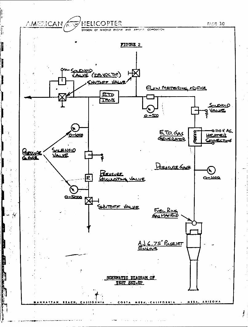
2. Schematic Diagram of Test Set-Up .. . . . .. 10
3. Vapor Pressure of Ethylene Oxide . 3.1
14. Ethylene Oxide Test Results . . . . . . 12
.TO Fuel Ring for Axial Injection. . . . . 13
6. Ef i 'Fui Ring for Radial Injection. . . . . 13
7. ETO Fuel Ring for Injecting ITO Decomposition Gases 14
8. ITO Fuel Ping for Injecting Gasoline, Gasoline andLiquidETO,and Liquid " . . . . . . 14
S9. Engine on Test Stand with ETO Manifold Attached,"Showing Broken Connection Resulting from ExplosiveFailure of EIT Gas Generator . . . . . . 15
10. ITO Gas Generator on Test Stand and STO Service*• Tanks and Plumbing . . . . • . • 5
3.11. ETO Fuel Flow and Pressure Regulating Panel. . . 16
12* ETO Test Setup Shoing Gas Generator, Manifold,and Test Engine 16
TAKER NO.
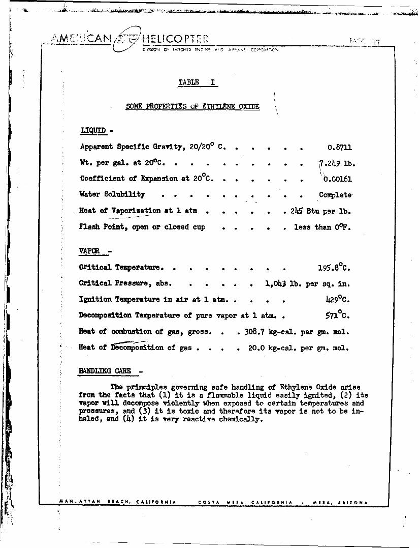
! I. Some Properties of Ethylene Oxide . . • • • 17
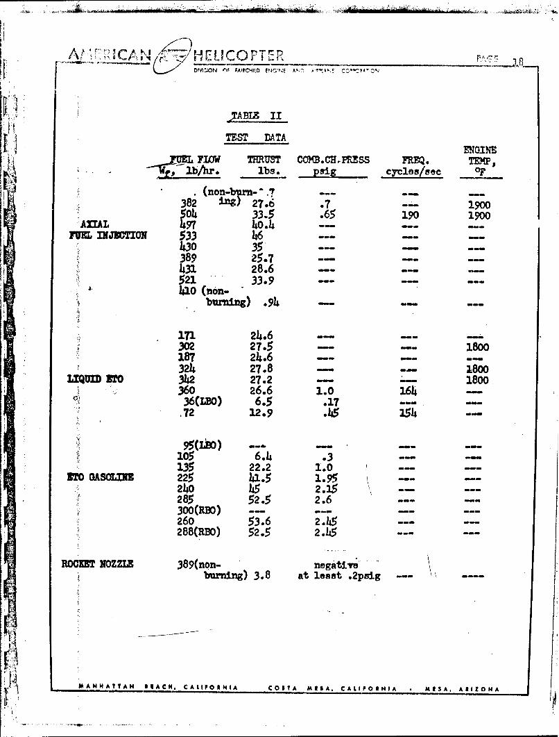
II. Test Data. . . . 18
MA .N AH ,AN I EACH, CALIPORNIA COSTA MISA. CALIFOSNIA • M;.SA, ARIZONA
AMERICAN HELICOPTER PAGE 1DI~ON OF PANCHOM V40"N AMO AIAU CO&OSATK*
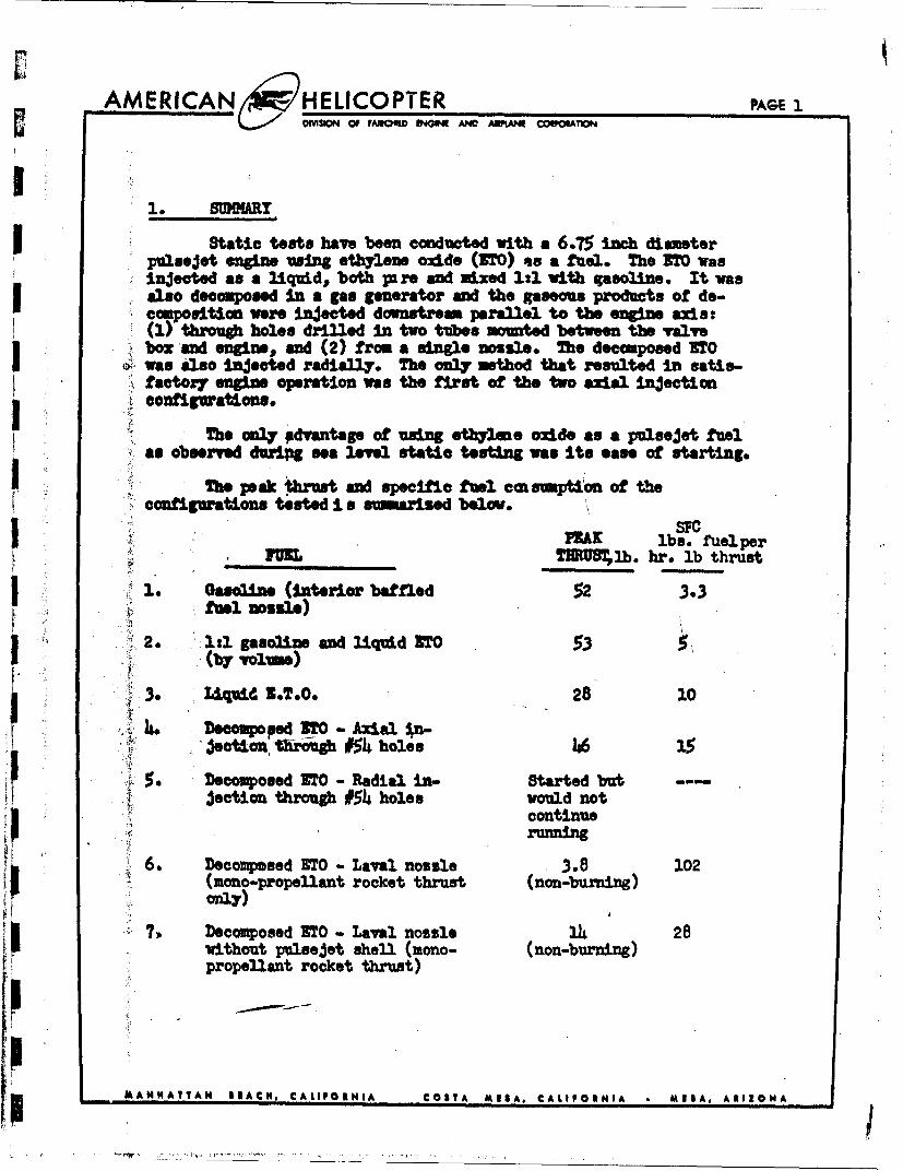
SMAR
Static teats have been conducted with a 6.75 inch diameterpulsejet, engine using ethylene oxide (ITO) as a fuel. The IMO wasInjected as a liquidv both pare and mixed 1:1 with gasoline. It wasalso decomposed In a gas generator and the gaseous products of de-composition were Injected dounstremn parallel to the engine axis :
box and engine,9 and (2) from a single nozzle. The decomposed ITO
factor7 engine operation was the first of the two axia Injection
coniguatinsThe only pdvantage of using ethylene oxide as a pulsejet fuel
Mhe peak tbutadspecific fuel connsuption of theconfigurations tested i s sinarised below.
SFCPEX lbs. tuelper
____M __ T~nRUT2b. hr. lb thrust
1. Ga@04ole (interior baffled 52 3.3fuel nossle)
2. 1:1 gaso3ln and liquid ITO .53I ~(by volume)
3., Iquid. ET.0. 28 10
U 6. ~~Decomposed sTo - Axavl poi- 38 0(monopoplan oce thrus nnbring) 5 oe 61
6. Decomposed ETO - Laval nozzle 3.8 128
without pulsejet shell (mono- (non-burning)propellant rocket thrust)
pMANHATTAN IRACH, CALIPORNIA COSTA MESA, CALIFORNIA *MESA, ARIZONA

AMERICAN HELICOPTER PAGE 2DIVISION OF FAMCO4IID INGINI AND ADWLANI CCRPOtATIOI4
2. ITDCTON
IAn investigation of the performance of ethylene oxide as afuel,, in Liquid form as the sole fuel and also mixed vith gasoline,, andas gaseous decomposition products from a rocket type gas'generator, wasconduncted tinder the thrus~t augmentation provisions of Supplement 5 ofI ~Exhibit NAN of Contract No. A? 33(600)-5860. Ethiylene oxide diff.~sfrom the fuels commonly used In a pulsejet engine, mailyl bwe-scot it can beused as either a bl&.propeflant or a monoo-provellant. In the latter case
U ~it decomposes into a mixture of gases idiom heated to a temperature of10600?P. In this form It Is used a- a mono-propellant rocket fuel. However,,these gaseous decemposition produxt will, bur nwen mixed vith air. It Is
onthis latter basis as a gaseous bi-propellant, that 'frami,-rocket" operationhsbeen predicted by other investigators. An interesting adjunct to this
study of ethylene oxide as a pvlsejet fuel, Is consideration of a "pulse-rocket' jet propulsion system., also intended to burn the gaseous decompo-
sition products.The entire eftylene oxide fuel system including control panel.,
fuel tanks,, and gas generator vs furni shed b~y the Turbo EngineeringDepartment ggf.the-American Machin~e and Foundry Company. Technical assis-tamce was also provided for operation of the fuel system throughout the
I testing phase of the program.
3. TUT EQUIMEnT
1 - 6.75" engine, No. M1(02
3 - 6.75" valve boxes1 xa necinuirnI - Radial injection fuel' ring
I - Delav aL nozzle
1 - Spark plug, .06" gap
1 - 3.8" dia. venturi
I1- Standard fuel system with 20 gph fuel nozzle and baffle
1 1 - I.T.0. gas generator
2 - I.T*0. service taniw aid valves
MIAA NHMATT AN I RACHNo CALIFPO IIINIA COSTA MIRA, CA LIFORNIA * MESA, ARIZONA
AMERICAN ELICOPTER PAG
1 - N.T.O. supply tank
1 - B.T.O. control panel
1 - Nitrogen pressurization tank
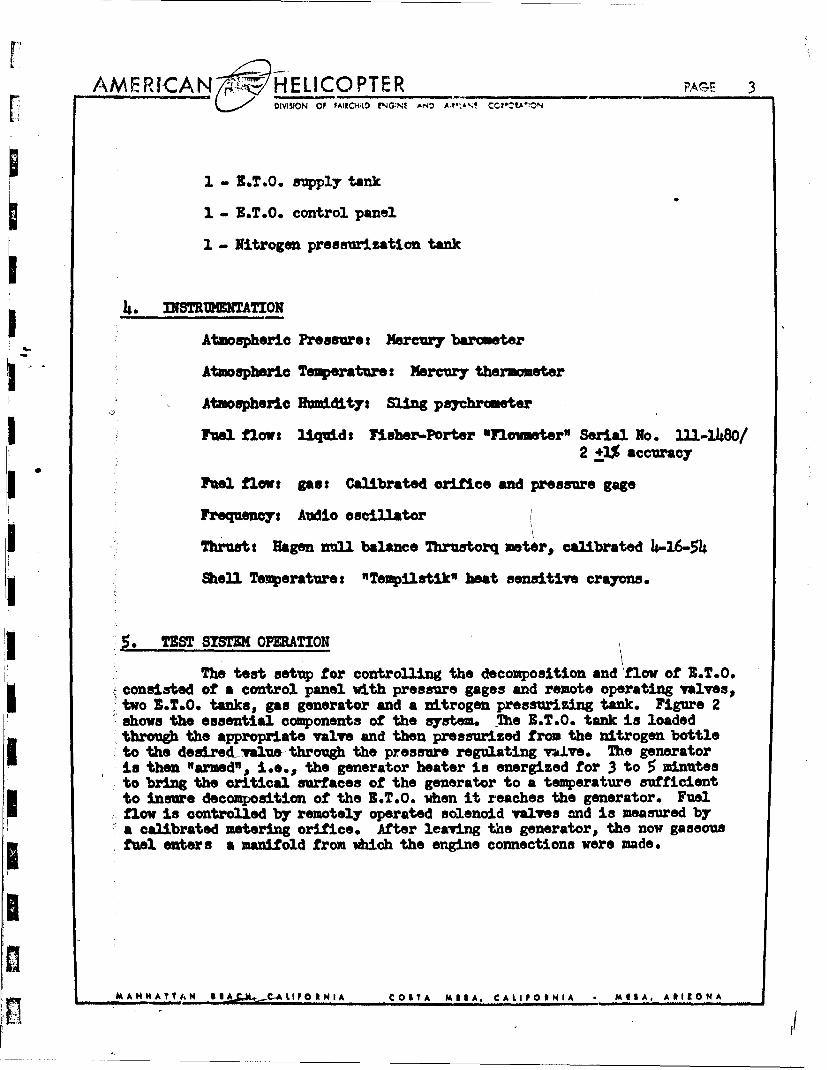
1. • INSTRMENTATION
Atmospherle Pressuret Mercury barmeterAtmospheric Temperature: Mercury thermmeter
,• Atmespherie Humidity: Sling psychrmeterSFuel flow: li•q id: Fisher-Porter "Flounetr" Serial No. 11-o1480/
2 2:3$ accuracy
Fuel flowt: gas: Calibrated orifice and pressure gage
Frequency: Audio oscillator
I • "Thrusts Hagen null balance Thrustorq meter, calibrated 4-16-&4
Shell Temperature: "TeNpilstik" heat sensitive crayons.
ITEST SSTEM OPERATION
The test setup for controlling the decomposition and flow of B.T.O.- consisted of a control panel with pressure gages and remote operating valves,
Stwo N.T.O. tanks, gas generator and a nitrogen pressurizing tank. Figure 2shows the essential components of the system. The B.T.O. tank is loaded
:through the appropriate valve and then pressurized from the nitrogen bottleto the desired-value- through the pressure regulating valve. The generatoris then "armed", i.e., the generator heater is energized for 3 to 5 minutesto bring the critical surfaces of the generator to a temperature sufficientto insure decomposition of the .T.O. when it reaches the generator. Fuel
" flow is controlled by remotely operated solenoid valves and is measured bya calibrated metering orifice. After leaving the generator, the now gaseous
i •fuel enters a manifold from which the engine connections were made.
M
S~~~MANHATTAN lSlAJ,,M.~....-AUPlOSINIA COSTA MESlA, CAI.IPOIRNIA * MEISA, ARIZIONA

AMERICANc ~HELICOPTER AN? E~L),
The B.T.0. tank held fuel for about 5 minutes of runxd~ng afterwhich the pressurizing tank was shut off and the I.T.O. tank vented toI ~atmosphere and refilled.
6.1 Properties
I Iftylene oxide is a cyclic ether (C2K~) It is a colorlessliquid that fremes. at -1690F and boill. at 5107. Some properties of thepvecamound In both the liquid and vapor states are given in Table I. I.T.O.I ~is a very volatile liquid with a specific gravity of 0.87. It burns likegasoline as a liquid and also vehen decomposed and mixed with adequate air.Storage of the liquid In an aircraft or in supply tanks requires pressurized"vessels since It has a vapor pressure of 85 psig-at 2600?. Further detailsas to the properties., storage and handling of X.T.0. are presented ini thereferenced literature from which Figure 3 and Table 33 are extracted.
1 6.2 Doecmposition
Under certain conditions of temperature and pressure, aI conttefled decompooition of B.T.O. may be maintained in a device such as theB.T.0. gas generator used in these tests. The liquid is injected into asafl" stesel chamber that contains a heating element that is energized several
I minutes before-firing to provide a temperature sufficient to ensure decompo-sition. Onc4estarted, the exothermic reaction of decaompoition maintains
itslf itlutfurtizir heating. The reaction by chemical analysis is asI follows:
I ~CAH-0-.92CO + .79CM14 + .239 2 .+0C 1 + .02C0 2 + .0202 + .09C + 870 BTU
Subsequent burning of the combustible mixture will yield an additional10s,830 ETtY/pound. The liquid and decomposed B.T.O. burn similarly to liquidgasoline and gasoline vapor,, respectively.
7. DISCUBSION 01PRasuLT
7.1 Performance with Gasoline
I ~For purposes of comparison a typ4 cal static engine p~erf or-mance cur"e is shown In Figure ii for an engine burning gasoline. Puel flow
94 varies from 75pph to l80pph from lean blowout to rich blowout with a peakthrust of 52 pounds and a specific fuel consuiption of about 3.3 at peak
VAMANHATTA N ROACH. CALIFORNIA C0S3T A MESA, CALIFORNIA MESA, ARIZONA

AMERICAN 14w/HELICOPTER FAG[ & DWIiSION Of PAOILD ENOINI ANC ATM-A' CO'"TAON
The engine (Figure 1) and fuel injection system for thisgasoline test run were the same as used for the liquid B.T.O. and 1/2 gaso-Uine, 1/2 B.T.O. test runs.
7.2 Liqm-d L.T.o.
Liquid E.T.O. was sed as a fua in the same configurationas was used with gasoline. Peak thrust was only about 50% of the gasolinepeak thrust with a corresponding specific fuel consuption of about 10. Itwas inferior in performance, therefore, as compared to gasoline both forthrust and specific fuel consumption. The fuel flow range was from 35 pphto 6 pph.
S3 Z.T.0. Gasoline Nixture (ll By Volum)
E.T.0. and gasoline were mixed in the B.T.O. service tanksin a ratio of 1l:. This mixture was then burned as a pulsejet fuel in thesame engl and fuel system Configuration as the gasoline test run. Peakthrust was 53 pounds which is essenftally the same as obtained with gasolinebut the specific fuel consumption at peak thrust was about 5 compared to3.3 for gasoline. The fuel flow range varied free 100 pph to 290 pph.
7A B.T.O. Decomposed (Gaseeus Products of Decomposition)
7.4.1 Axial Fuel Injection
The B.T.O. decomposition products were burned in the sameengine as above but with a different fuel Injection system. Fuel was in- -
Jeoted into the combustion chamber by means of an axial fuel injection sys-tam that consisted of a modified gasoline fuel ring. The nozzle baffleand supporting fuel tube were removed from a gasoline fuel ring (Figure 8)and two l/4" O.D. x .035" steel tubes %ere added with 10 #54 holes drilledon the downstream side of the tubes (Figure 5). The engine started veryeasily with only a momentary blast of starting air. Peak thrust obtainedwas about 40 pounds which was apparently near rich blowout, although thelimit of flow available from the test setup was reached and a \definite maxi-mom fuel flow was not established. The fuel flow ranged from 385 pph atlean blowout to a maximum obtainable flow of 535 pph. Specific fuel con-swption was 15 at 40 pounds of thrust.
MANHATTAN BW1ACH, CALIPO IENIA COS1TA MNSA, CALIFO RNIA M MSA, ARIZONA

AM~1CA r'§ýHELICOPTER Et'IVISKON OF FAMCK#I) ENGINI AND A~jk"N! CC*"L'ý>WN
7,4.2 Radial Injection
Another mojified gasoline fuel ring' was wsed to pro-rideradial in~jection of the decomposed X.T.O. A 6.75,, fuel ring was drilledvith 16 No. 54 holes around the inside of the ring (Figure 6). This sysý-tem-provided mowmntary starting but would not continue to run. The 3.T.0.1pgase could be aeen escaping -forwar-d through the valves., so that, it wasprobable that combustion air., that must enter through the valves., was be-Ing r.ostricted by the large volume of Injected B.T.O. gases.
7.4.3 Rocket (Do Laval) Nozzle
A third and final fuel injection configuration CMigre 7)I was tried during performance testing of the gaseous products of the B.T.O.gas generator, A Do Laval nozzle was installed so as to expel the gases anton the engine centerline in an attempt to utilize, any available thrust from1 the rocket-nessl.-in-addition to the basic pulsejet thrust. This Is ena-logous to the basic Idea behind the "ram-rocket" configuration. No st-artswere achieved with this system. It appeared that the jet of hot gases vasI ~not spreading and filling the combustion chamber., but vas escaping out thetailpipe without forming a combustible mixture with air. It seowed likelythat if the hot gases Impinged on a baffle located downstream of the rocketI ~ ~nozzle, adeuate amixng with air might occur; however, this would practically
eliintethe thrust ef the rocket nozzle and thus defeat the purpose forwdmng the rocks'b-nossle. Since Only 3.8 pounds of non-burning thrust veraobtained with'this configuration (giving an ef c of about 102) it wasn notI ~considered practicable to devlop the engine to operate with this sytstemThe tbru ft of the rocket nozzle when outside the pulsejet, shell was 14~pounds %givlng an afe of about 28). The difference in thrusts musat bedue to internal drag between the rocket jet and the pulsejet shell.
7 49perating Temperatures
1 In general,, the pulsejet, operation with Z.T.0. as a fuelresulted in engine shell temperatures of about 19000"?, vhich is 200 to 30"?
ýhigher than encountered with gasoline fuel. One effect of the hotter engineI was to accentuate the decrease in thrust at constant fuel flow when anengine Is warming up to operating temperature,, that has been observed to alesser ext~ent with gasoline. The scatter of data shown :in Figure 14 forJ the decomposed 3J.0. Is due in part to the above effect.
#AANNHATTAN SIACH, CALIFORNIA COS T A MESA, CALIFORNIA MISA. ARIZONA

7.6 Leakage Problem
Leakage of the hot gases tbit leave the gas gen'ertor athigh temperatvxe (1700 0F) and pre~sure (1000 psig) reqvired consnt re-tightening of fittings after each r n. A .- ry small le'k in a screvedconnection vrE-iogressively worse, apparently dre to erosion of thefitting. Close tolerance screw fittings or welded co ctions would benecessary to insure troeble free operation of this fuel system piping.
7.7 Generator Surging
Directly associatee with gas leaks was a form of insta-bility of the generator known as "chugging" or surging. If the pressureat the generator inlet wms too low or if the outlet pressure was too low,the flow throug the generator would start to surge at a low frequency(about one cycle per second) but at high amplitudes. During the secondday of testing the above difficulty caused failure of the nuts securingthe head of the generator to the chamber (Figure 9). A subsequent stain-less steel. generator gave satisfactory service throughout the subsequenttest, 9aliough "chugging" was not entirely eliminated. Leaks in the gen,-erstor lines were corrected as far as could be ascertained but generatorsurge persisted. Slight variation in the properties of the delivered3.T.O. was thought to be a possible source of the difficulty.
7.8 Valve Box Life
Valve box life was shortened due to the higher engine andcombustion temperatures that resulted from using R.T.O. The engine wasnot run long enough to determine valve life under steady operating condi-tions, but it was obvious that the valves were being damaged by heat in afew minutes of running time. The burning was partly due to the fuel in-jection location being 1/14" aft of thi4 reeds which allowed the combustionto start at the venturi with resulting ,high temperatures occuring 2 to 3inches forward of a station that would be normal for gasoline. Enginetemperature when running on the decomposition products was measured with a"ITempilstik't crayon and showed a value of 190OO~F over nearly the entireengine which is several hundred degrees higher than normal test standoperation with gasoline. The high temperatures were not restricted toparts of the tailpipe, transition, and combustion chamber as with gaso-line, but appeared to spread uniformally over most of the engine.
M ANIHAIA W AIACH, CALIFORNIA COSTA M1SA, CAIIP0RNIA MM3A. ARIZONA

Y E
SDIVTIN OF 1
7.9 Engine Frequency
All of the test runs burning E.T.O., both liquid and gaseou.s,provided frequency data that revealed an engne resonant frequency rangingfrom 23% to 52% higher than its resonant frequency when burning gasoline.The natural frequency of the valves was about 190 cycles per second and theaverage recorded engine frequency was about 170 cycles per second, witJ, P
resulting ratio of natural frequency to average forcing frequency cf .. 1.32.
7.10 SYstem Weight
The weight of the test stand components for the E.T.O. testswas about 600 pounds which includes the nitrogen pressurizing tank and theE.T.O. sBupply tank but does not include fuel. An estimate for the weightthat night 1,e expected for a .J•ing version of the fuel syste-m, would be112 pounds. At600 poamds per hour per engine for 40 pounds of thrust, 1200pounds of E.Z.O. would be required for a one hour flight. About 1300 poundsof fuel and fuel system would be required therefore, for a two-engined
single-place aircraft to fly one hour.
8. CONCLUSIONS
Sea level static testing has shown ethylene oxide to be inferiorto gasoline as a pulseJet fuel with respect to thrust, specific fuel con-sviption, system complexity, fuel handling, and system weight. Ease ofengine starting was observed during this program to exceed performance withgasoline.
MANHATTAN AEIACH, CAt IPOF N IA CO0 TA MISA, CALIFOUNIA MIIA, AIt ONA

AMEPICAN HELICOPTER - 9OIV!SION OF FARICHILD EN'I. ANC •I•un•
MA kAN HAT TAN
'E A CH, CAJl
PF 0 tN| IA COS T A MI f
SA. C A LI FO R N IA
ME1S5A, ARI
tIZO0N A
[HH
r-7
IJIt
MP2iA 7. ~ A____________ trJ 1107
D~~ IVISION Of WA'CHILD FNGj-4! AND Aý.A-': CC"OLATCN
MUM~? 2
Fý
cv. T6 A
~~Nit
AkANNHATT AN I IA CH, COSId I C05T A M I IA',-CAL IF PI A MIRA, ARIZONA

A/W"'JCAN H, HE L OOPTErl,- R
DIV!SION Of FAICHITLD E4G! NE ANO A'?"' CCt--ZIA'
400- -m/300-
I ~ ~~ ~~~~200-" - -
I/80-- -- - -
70 1 1/60 --50
0 20
* p 4 7- -- - --- ---
4-- -- ---- ---
U 2o -/
.0.50--4--
,0.0
h -58 -4 -22 -4 14 32 50 68 8534 14o 176 212 302TEIEPATURE, OF
Fig-re 3 VAPOR PRESSURE OF Ln OXIDE
M A MANHATTAN IIACH, CALIFORNIA C COSTA MESA, CALIFORNIA M NSA, ARIZONATV -HA TA ............ **.~ '

H~EL1COPT Ar'
'17' A A'2
XII0
Ct0
252
MI #
0jmoall
I1 4

A -~AN r~~HELICOPTER~pAfC1
I ~~~~~~IVISION OF FýA't 'A~*~A'"
FIGMTES
ErO FUEL RING FOR AXIALINJECTION. RING IS IN-II STALLED 5O THAT HOLESFACE DLOANSTREAM.
I ~FIGURE 6.ETO FUEL RING FOR RADIALINJECTION. NO PULSEJErOPERATION WAS ACHItEVEDWITH THIS SISTBE1.
I iM A N HA T TIAN BEACH. CALIfO R NIA C O0S TA M EFS A. C A LI F 6MN IA M E S5A. AR I Z ONMA

A NA r"A C -H L ICO PTEP __ ~zOF FAPClitr '~ ' ~
FIGURE 7.
TTO FUEL RING FOR INJECT-I;G ETO DECOMPOSITION GASES.7H¶E RING WAS INSTALLE WTT HTHE LAVAL NOZZLE (NOT SHOWN)FACING DOWNSTREAM. NO PULSE-JET OPERATION WAS ACHI EVE D'WITH THIS SYSTEM.
Erb FUEL RING FOR INJECTINGGASOLINE., GASOLINE ANDLIQUID ETO., AND LIQUID ETO.THE RING WAS INSTALtED WITHTHE NOZZLE FACING DOWNSTREAm.
2521
-MA NH A TT7AN BEACH, CALIPO RNIA CO0S TA MESA, C ALIFO NNIA M 13A , A 01ZON A
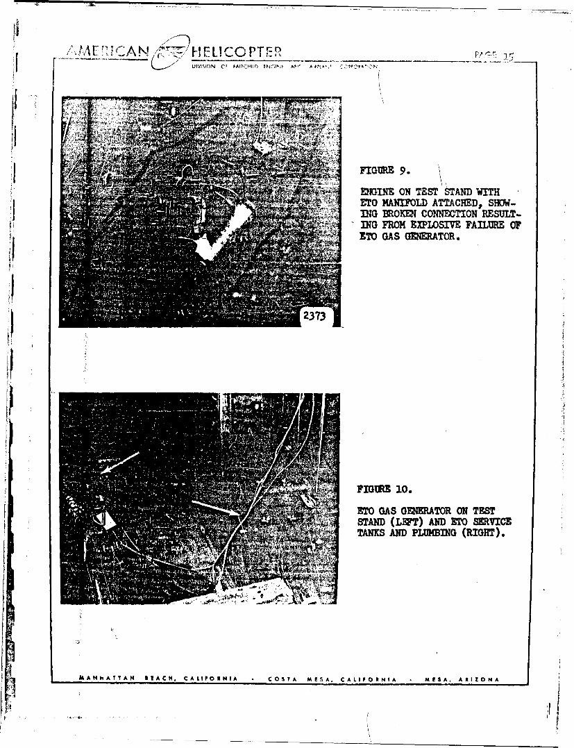
VIVIENGIN ON TESTCO STAN WITHA
ETO MANIFOLD ATTACHED, SIKWv-A TING EROKENI CONNETION RESULT-ING FROM EXPLO)SIVE FAILURE OF970I' GAS GMNERATOR.
FIGW.E 10.
ETO GAS GENMER ATOR ON TESTSTAND (LEFT) AND ETO SERVICETANIKS AND PLUMETUG (RIGHT).
MANhATTAN BEIACH, CALIFORNIA COSTA MESA, CALIFORNIA MESA, ARIZONA

';,F2LICOPTER _______
II~* .~'ETO FUE FLOW !ND PRESSURE
REGUATING PANEL. TME IN-STRUMENTS TO THE LEFT ARENOT PART OF THE SMSEM.
1ý4 FIGURE 12.
ETO TiST SIM S[OWING OASGMGATOEs, MANIFOLD,AIID TESTENINE, IN CRE FROM THE IEPFT
I THE FOUR 1/4" O.D. IUHS CON-.ApNECT THE MAVCIFOLD TO THE FME
M A N.AITTANH BEACH, CAkIIPOENIA C. CST7A MESA, CALIFO INIA M1S3A , A 0 1ZON A
DIV!SVON OF FA!RHIMD E O AT' , CC~t•:WýCN
TABLE I
SOME• •OP1TIS OF ETHrN OXI0=
LIQUID -
Apparent Specific Gravity, 20/200 C . . . .. 0.87f1
SWt. per gal. at 200C. .. ... '7.249 lb.0\
Coefficient of Expansion at 20 • • . . . . .C0161
Water Solubility Complete
Heat of Vaporization at 1 atm . • . . . . 245 Btu psr lb.
Flash Point, open or closed cup . . . . . less than O°F.
VAPOR-Critical Temperature. . .. 195.8°C.
Critical Pressure, abs. 1 .• • . 1,04t lb. per sq. in.
Ignition Temperature in air at I atm . . .. . 429°C.
Decomposition Temperature of pure vapor at 1 atm.. 5710C.
Heat of combustion of gas, gross. • 308.7 kg-cal. per gm. mol.
Heat of Ncomposition of gas . . . 20.0 kg.cal. per gm. mol.
HANDLING CARE -
The principles governing safe handling of Ethylene Oxide arisefrom the facts that (1) it is a flammable liquid easily ignited, (2) itsvapor will decompose violently when exposed to certain temperatures andpressures, and (3) it is toxic and therefore its vapor is not to be in-haled, and (4) it is very reactive chemically.
MAN;:ATTAN REACH, CALIFORNIA CO.TA MESA, CALIFORANIA M1SA, AkIZONA
-I ,
DIVI:40N OF FA'?~IWMCD v~ 7,, -A c:'& .p
IL TABTA II
TEST DlATAENGINE
UEIL-q P.ww THRUST COMB.CH.PSS F'REQ. TmeqPh Zjb4r. lbs. cyls/e OF
(non-blim..".- ...
382 n) 27o6 .7 -- 1900ý.. 33.5 .65 190 1900
MflAL 1497 40o.4 -. -.F M•!JCION 533 46 ......
1430 35 *-389 25.71431 28.6 ......521 33.9 .....1410 (non-
bur'ning) A9&
171 24.6302 27.5 --- - 1800187 24.6 ..---3214 27.8 fe -- 1800
LIQID STO 342 27.2 1- - 800360 26.6 1.0 164-
36(LeO) 6.5 .17 --0e.72 12.9 .45 '5-4
95(LbO) ea fe.&e fe
105 6.14 .3 -- -135 22.2 1.0 1 ....
STO GASoI 225 41.5 1.9 95.....240 45 2.15 -.
285 52.5 2.6 --- ---300(RBO) .260 53.6 2..45.-..288(RBO) 52.5 2.o5
ROCIT NOZZLE 389(non- negative"burning) 3.8 at least ,2p-ig ,
-$A ANNATT AN .. ACN' CALIPONHIA C,,OSTA MISA. CALIPOINIA MISA, ARIZONA