ams 2140 operating notes: machinery health analyzer...for laser shaft alignment ams 2140 machinery...
TRANSCRIPT

Optional – Job Storage
Alignment jobs can also be saved and printed.
This is found under “Job Manager” on the ALT screen of the main menu.
You can customize the machine graphics using a selection of different machine types. Consult the user manual for additional details, advanced functions, and instructions.
Pocket Guide For Laser Shaft Alignment
AMS 2140Machinery Health™ Analyzer
Refer to the user manual to learn how to upload saved jobs back to the PC software.
Introduction:
This guide outlines a quick and easy 3-step method for precision shaft alignment.
Set-up:
Choose the shortest support posts that will still allow the laser beam to pass over or through the coupling. Mount the laser fixtures by sliding each head over the support posts and locking them into place with the yellow clamping levers. Mount laser heads as shown above, being careful to mount the laser on the stationary machine.
Sweep Size:
The “Auto Sweep” method provides a simple, accurate solution for any alignment task. Start anywhere. Stop anywhere. While it is always best to completely rotate the shaft, this method can be used effectively with partial sweeps down to 45°. Press [ENTER] to retrieve data via Bluetooth.
45°
Operating Notes:Laser fixtures are for shaft alignment only and should be operated by properly trained personnel. As precision instruments, care should be taken to not subject them to shock.
Laser Safety: � Do not stare directly into the laser beam!
[NOTE: Red LED on Laser Head indicates that laser is active.]
� Do not insert optical devices into beam.
P/N
: MH
M-9
7109
, rev
1
Mount laser on stationary machine
Mount sensor on machine to be moved
AMS 2140 Machinery Health™ Analyzer
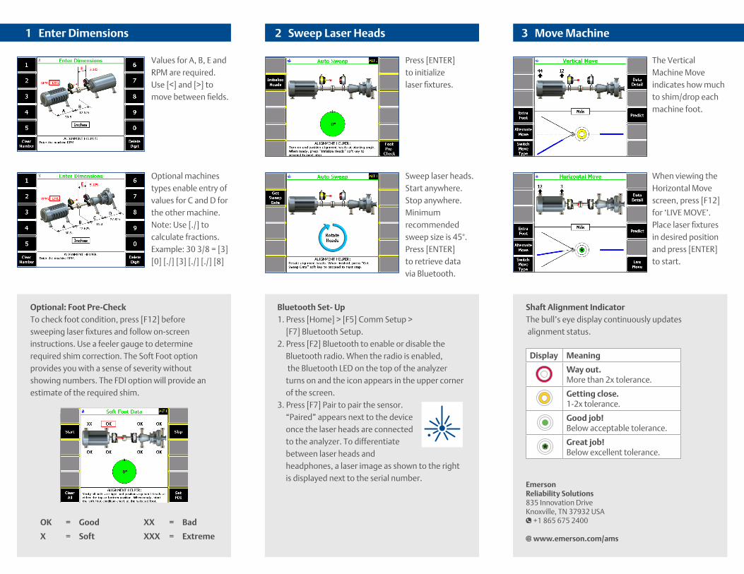
Optional: Foot Pre-CheckTo check foot condition, press [F12] before sweeping laser fixtures and follow on-screen instructions. Use a feeler gauge to determine required shim correction. The Soft Foot option provides you with a sense of severity without showing numbers. The FDI option will provide an estimate of the required shim.
Bluetooth Set- Up 1. Press [Home] > [F5] Comm Setup >
[F7] Bluetooth Setup.2. Press [F2] Bluetooth to enable or disable the
Bluetooth radio. When the radio is enabled, the Bluetooth LED on the top of the analyzer turns on and the icon appears in the upper corner of the screen.
3. Press [F7] Pair to pair the sensor. “Paired” appears next to the device once the laser heads are connected to the analyzer. To differentiate between laser heads and headphones, a laser image as shown to the right is displayed next to the serial number.
1 Enter Dimensions 2 Sweep Laser Heads 3 Move Machine
Values for A, B, E and RPM are required.Use [<] and [>] to move between fields.
Optional machines types enable entry of values for C and D for the other machine. Note: Use [./] to calculate fractions. Example: 30 3/8 = [3] [0] [./] [3] [./] [./] [8]
Press [ENTER] to initialize laser fixtures.
The Vertical Machine Move indicates how much to shim/drop each machine foot.
Sweep laser heads. Start anywhere. Stop anywhere. Minimum recommended sweep size is 45°. Press [ENTER] to retrieve data via Bluetooth.
When viewing the Horizontal Move screen, press [F12] for ‘LIVE MOVE’. Place laser fixtures in desired position and press [ENTER] to start.
OK = Good
X = Soft
Display Meaning
Way out. More than 2x tolerance.
Getting close. 1-2x tolerance.
Good job! Below acceptable tolerance.
Great job! Below excellent tolerance.
Shaft Alignment IndicatorThe bull’s eye display continuously updates alignment status.
EmersonReliability Solutions 835 Innovation DriveKnoxville, TN 37932 USA
+1 865 675 2400
www.emerson.com/ams
XX = Bad
XXX = Extreme