an active acoustic metamaterial with tunable effective · pdf filean active acoustic...
TRANSCRIPT
PROOF COPY [VIB-09-1159] 017002VAJ
PROO
F COPY [VIB-09-1159] 017002VAJ
Amr M. BazDepartment of Mechanical Engineering,
University of Maryland,2137 Engineering Building,
College Park, MD 20742e-mail: [email protected]
An Active Acoustic MetamaterialWith Tunable Effective DensityExtensive efforts are being exerted to develop various types of acoustic metamaterials toeffectively control the flow of acoustical energy through these materials. However, allthese efforts are focused on passive metamaterials with fixed material properties. In thispaper, the emphasis is placed on the development of a class of one-dimensional acousticmetamaterials with tunable effective densities in an attempt to enable the adaptation tovarying external environment. More importantly, the active metamaterials can be tailoredto have increasing or decreasing variation of the material properties along and acrossthe material volume. With such unique capabilities, physically realizable acoustic cloakscan be achieved and objects treated with these active metamaterials can become acous-tically invisible. The theoretical analysis of this class of active acoustic metamaterials ispresented and the theoretical predictions are determined for an array of fluid cavitiesseparated by piezoelectric boundaries. These boundaries control the stiffness of the in-dividual cavity and in turn its dynamical density. Various control strategies are consid-ered to achieve different spectral and spatial control of the density of this class ofacoustic metamaterials. A natural extension of this work is to include active controlcapabilities to tailor the bulk modulus distribution of the metamaterial in order to buildpractical configurations of acoustic cloaks. �DOI: 10.1115/1.4000983�
Keywords: active acoustic metamaterials, programmable metamaterials, acoustic cloaks
1 IntroductionThe development of metamaterials with optical, electromag-
netic, and acoustical properties that are unachievable with naturalmaterials have attracted considerable interest during the last de-cade �1–3�. In particular, the development of the acoustic metama-terials has been motivated by the need for understanding the un-derlying phenomena governing the operation and practicalrealization of effective acoustic cloaks that can be used for treat-ing critical objects in order to render them acoustically invisible.An excellent review of the basic phenomena and the history ofdevelopment of cloaking are presented by Milton et al. �4�.
The pioneering work of Cummer and Schurig �5� establishedtheoretically that two-dimensional acoustic cloaks are possiblethrough the use of acoustic materials that have strong anisotropy,which do not exist in nature. Since then extensive efforts havebeen exerted to broaden the theoretical foundation and investigatepossible means for realization of effective acoustic cloaks. Dis-tinct among these efforts are the works of Cummer et al. �6� andNorris �7� about the basics of the theory of acoustic cloaking.Torrent and Sanchez-Dehesa �8,9� comprehensively investigatedthe theory governing the development of multilayered in order toachieve the anisotropy requirements presented by Cummer andSchurig �5�. Other efforts along the same direction have beencarried out by Popa and Cummer �10�, Cheng and co-workers�11,12�, and Cheng and Liu �13� to study either two- and/or three-dimensional layered metamaterials. The improved design of theacoustic cloaking using an impedance matching approach is pro-posed by Chen et al. �14� in order to avoid the infinite massproblem of the ideal cloak of Cummer et al. �15�.
Acoustic metafluids consisting of layered composite mediahave also been considered. These metafluids have either aniso-tropic density and scalar bulk modulus �16� or anisotropic densityand bulk modulus �17�.
Unlike the extensive theoretical studies of acoustic metamate-
rials, the experimental investigations are by far lacking. However,an important experimental study that is relevant to this paper isthe work of Lee and co-workers �18,19�, which demonstrated thenegative effective density characteristics of an acoustic metama-terial consisting of an array of cavities separated by thin elasticmembranes. Similar results were reported by Yao et al. �20� usinga spring-mass system.
In all the above studies, the focus has been placed on passivemetamaterials with fixed material properties. This limits consider-ably the potential of these materials. In this paper, the emphasis isplaced on the development of a class of one-dimensional acousticmetamaterials with tunable effective densities, which can be tai-lored to have increasing or decreasing variation along the materialvolume. With such unique capabilities, physically realizableacoustic cloaks can be achieved and objects treated with theseactive metamaterials can become acoustically invisible.
This paper is organized in seven sections. In Sec. 1, a briefintroduction is presented. In Sec. 2, the concept of the activeacoustic metamaterial is introduced. In Secs. 3–5, lumped-parameter models of plain cavities, cavities with flexible dia-phragms, and cavities with piezoelectric diaphragms are outlinedin order to motivate the need for the active component to achievea “programmable” acoustic metamaterial. In Sec. 6, numericalexamples are considered to demonstrate the performance charac-teristics of the active metamaterial. A brief summary of the con-clusions and the future work are outlined in Sec. 7.
2 Concept of Active Acoustic Metamaterial
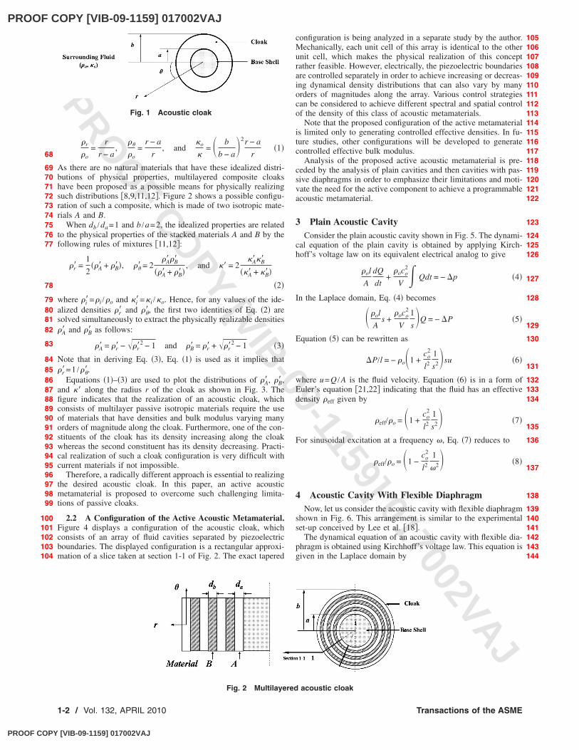
2.1 Why Active Acoustic Metamaterial?. In order to under-stand the need for an active acoustic metamaterial, consider thepassive acoustic cloak shown in Fig. 1.
For an ideal cloak, the required distribution of the density ��rand �� in the radial and tangential directions� and bulk modulus��� are given by �5�
Contributed by the Technical Committee on Vibration and Sound of ASME forpublication in the JOURNAL OF VIBRATION AND ACOUSTICS. Manuscript received July 21,2009; final manuscript received December 10, 2009; published onlinexxxxx-xxxxx-xxxxx. Assoc. Editor: Noel C. Perkins.
1
23456789
10111213141516171819202122232425262728293031323334
3536373839404142434445464748495051525354555657585960
61
626364656667
Journal of Vibration and Acoustics APRIL 2010, Vol. 132 / 1-1Copyright © 2010 by ASME
PROOF COPY [VIB-09-1159] 017002VAJ
PROOF COPY [VIB-09-1159] 017002VAJ
PROO
F COPY [VIB-09-1159] 017002VAJ
�r
�o=
r
r − a,
��
�o=
r − a
r, and
�o
�= � b
b − a�2r − a
r�1�
As there are no natural materials that have these idealized distri-butions of physical properties, multilayered composite cloakshave been proposed as a possible means for physically realizingsuch distributions �8,9,11,12�. Figure 2 shows a possible configu-ration of such a composite, which is made of two isotropic mate-rials A and B.
When db /da=1 and b /a=2, the idealized properties are relatedto the physical properties of the stacked materials A and B by thefollowing rules of mixtures �11,12�:
�r� =1
2��A� + �B��, ��� = 2
�A��B�
��A� + �B��, and �� = 2
�A��B�
��A� + �B���2�
where �i�=�i /�o and �i�=�i /�o. Hence, for any values of the ide-alized densities �r� and ���, the first two identities of Eq. �2� aresolved simultaneously to extract the physically realizable densities�A� and �B� as follows:
�A� = �r� − ��r�2 − 1 and �B� = �r� + ��r�
2 − 1 �3�
Note that in deriving Eq. �3�, Eq. �1� is used as it implies that�r�=1 /���.
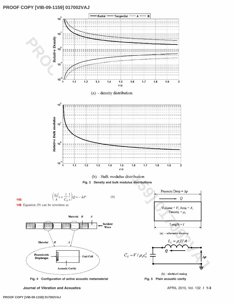
Equations �1�–�3� are used to plot the distributions of �A� , �B� ,and �� along the radius r of the cloak as shown in Fig. 3. Thefigure indicates that the realization of an acoustic cloak, whichconsists of multilayer passive isotropic materials require the useof materials that have densities and bulk modulus varying manyorders of magnitude along the cloak. Furthermore, one of the con-stituents of the cloak has its density increasing along the cloakwhereas the second constituent has its density decreasing. Practi-cal realization of such a cloak configuration is very difficult withcurrent materials if not impossible.
Therefore, a radically different approach is essential to realizingthe desired acoustic cloak. In this paper, an active acousticmetamaterial is proposed to overcome such challenging limita-tions of passive cloaks.
2.2 A Configuration of the Active Acoustic Metamaterial.Figure 4 displays a configuration of the acoustic cloak, whichconsists of an array of fluid cavities separated by piezoelectricboundaries. The displayed configuration is a rectangular approxi-mation of a slice taken at section 1-1 of Fig. 2. The exact tapered
configuration is being analyzed in a separate study by the author.Mechanically, each unit cell of this array is identical to the otherunit cell, which makes the physical realization of this conceptrather feasible. However, electrically, the piezoelectric boundariesare controlled separately in order to achieve increasing or decreas-ing dynamical density distributions that can also vary by manyorders of magnitudes along the array. Various control strategiescan be considered to achieve different spectral and spatial controlof the density of this class of acoustic metamaterials.
Note that the proposed configuration of the active metamaterialis limited only to generating controlled effective densities. In fu-ture studies, other configurations will be developed to generatecontrolled effective bulk modulus.
Analysis of the proposed active acoustic metamaterial is pre-ceded by the analysis of plain cavities and then cavities with pas-sive diaphragms in order to emphasize their limitations and moti-vate the need for the active component to achieve a programmableacoustic metamaterial.
3 Plain Acoustic CavityConsider the plain acoustic cavity shown in Fig. 5. The dynami-
cal equation of the plain cavity is obtained by applying Kirch-hoff’s voltage law on its equivalent electrical analog to give
�ol
A
dQ
dt+
�oco2
V � Qdt = − �p �4�
In the Laplace domain, Eq. �4� becomes
��ol
As +
�oco2
V
1
s�Q = − �P �5�
Equation �5� can be rewritten as
�P/l = − �o�1 +co
2
l2
1
s2�su �6�
where u=Q /A is the fluid velocity. Equation �6� is in a form ofEuler’s equation �21,22� indicating that the fluid has an effectivedensity �eff given by
�eff/�o = �1 +co
2
l2
1
s2� �7�
For sinusoidal excitation at a frequency �, Eq. �7� reduces to
�eff/�o = �1 −co
2
l2
1
�2� �8�
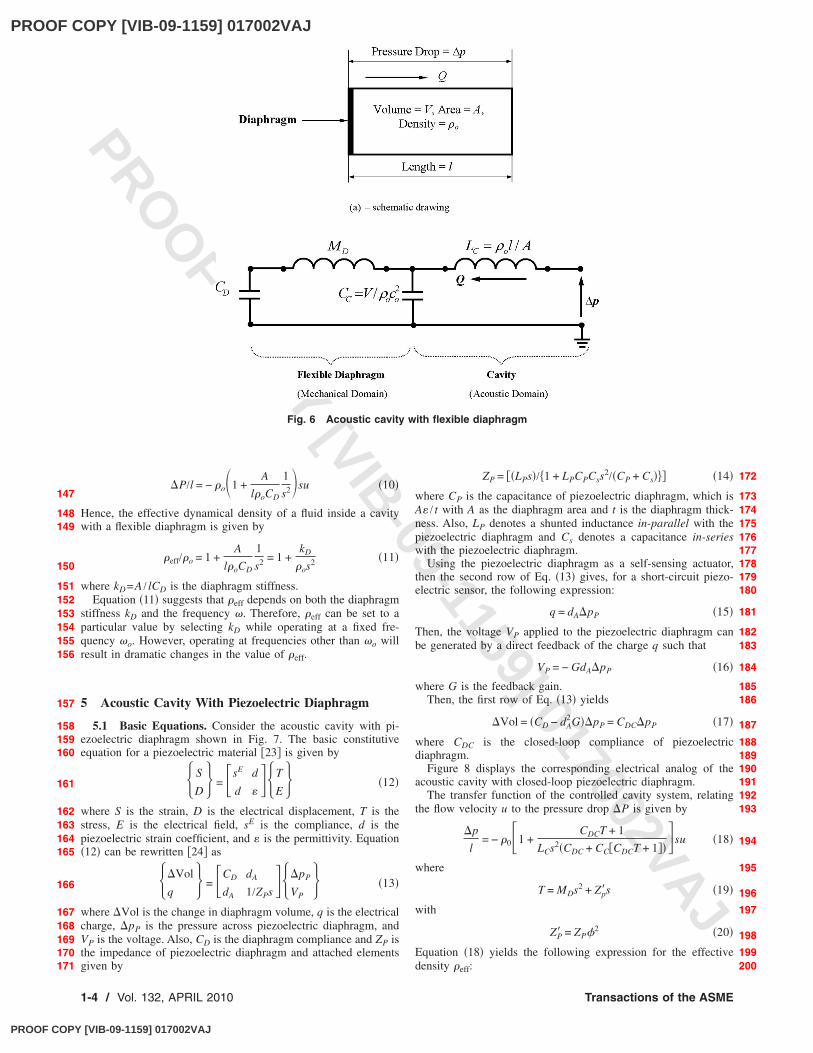
4 Acoustic Cavity With Flexible DiaphragmNow, let us consider the acoustic cavity with flexible diaphragm
shown in Fig. 6. This arrangement is similar to the experimentalset-up conceived by Lee et al. �18�.
The dynamical equation of an acoustic cavity with flexible dia-phragm is obtained using Kirchhoff’s voltage law. This equation isgiven in the Laplace domain by
Fig. 1 Acoustic cloak
Fig. 2 Multilayered acoustic cloak
68
697071727374757677
78
79808182
83
84858687888990919293949596979899
100101102103104
105106107108109110111112113114115116117118119120121122
123
124125126
127
128
129
130
131
132133134
135
136
137
138
139140141142143144
1-2 / Vol. 132, APRIL 2010 Transactions of the ASME
PROOF COPY [VIB-09-1159] 017002VAJ
PROOF COPY [VIB-09-1159] 017002VAJ
PROO
F COPY [VIB-09-1159] 017002VAJ
��ol
As +
1
CD
1
s�Q = − �P �9�
Equation �9� can be rewritten as
Fig. 3 Density and bulk modulus distributions
Fig. 4 Configuration of active acoustic metamaterial Fig. 5 Plain acoustic cavity
145
146
Journal of Vibration and Acoustics APRIL 2010, Vol. 132 / 1-3
PROOF COPY [VIB-09-1159] 017002VAJ
PROOF COPY [VIB-09-1159] 017002VAJ
PROO
F COPY [VIB-09-1159] 017002VAJ
�P/l = − �o�1 +A
l�oCD
1
s2�su �10�
Hence, the effective dynamical density of a fluid inside a cavitywith a flexible diaphragm is given by
�eff/�o = 1 +A
l�oCD
1
s2 = 1 +kD
�os2 �11�
where kD=A / lCD is the diaphragm stiffness.Equation �11� suggests that �eff depends on both the diaphragm
stiffness kD and the frequency �. Therefore, �eff can be set to aparticular value by selecting kD while operating at a fixed fre-quency �o. However, operating at frequencies other than �o willresult in dramatic changes in the value of �eff.
5 Acoustic Cavity With Piezoelectric Diaphragm
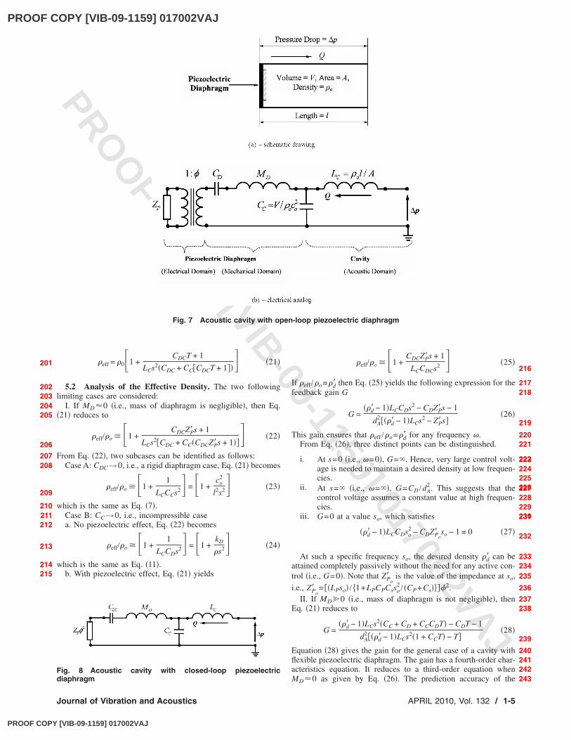
5.1 Basic Equations. Consider the acoustic cavity with pi-ezoelectric diaphragm shown in Fig. 7. The basic constitutiveequation for a piezoelectric material �23� is given by
S
D = �sE d
d ��T
E �12�
where S is the strain, D is the electrical displacement, T is thestress, E is the electrical field, sE is the compliance, d is thepiezoelectric strain coefficient, and � is the permittivity. Equation�12� can be rewritten �24� as
�Vol
q = �CD dA
dA 1/ZPs��pP
VP �13�
where �Vol is the change in diaphragm volume, q is the electricalcharge, �pP is the pressure across piezoelectric diaphragm, andVP is the voltage. Also, CD is the diaphragm compliance and ZP isthe impedance of piezoelectric diaphragm and attached elementsgiven by
ZP = ��LPs�/ 1 + LPCPCss2/�CP + Cs��� �14�
where CP is the capacitance of piezoelectric diaphragm, which isA� / t with A as the diaphragm area and t is the diaphragm thick-ness. Also, LP denotes a shunted inductance in-parallel with thepiezoelectric diaphragm and Cs denotes a capacitance in-serieswith the piezoelectric diaphragm.
Using the piezoelectric diaphragm as a self-sensing actuator,then the second row of Eq. �13� gives, for a short-circuit piezo-electric sensor, the following expression:
q = dA�pP �15�
Then, the voltage VP applied to the piezoelectric diaphragm canbe generated by a direct feedback of the charge q such that
VP = − GdA�pP �16�
where G is the feedback gain.Then, the first row of Eq. �13� yields
�Vol = �CD − dA2G��pP = CDC�pP �17�
where CDC is the closed-loop compliance of piezoelectricdiaphragm.
Figure 8 displays the corresponding electrical analog of theacoustic cavity with closed-loop piezoelectric diaphragm.
The transfer function of the controlled cavity system, relatingthe flow velocity u to the pressure drop �P is given by
�p
l= − �0�1 +
CDCT + 1
LCs2�CDC + CC�CDCT + 1���su �18�
where
T = MDs2 + Zp�s �19�
with
ZP� = ZP�2 �20�
Equation �18� yields the following expression for the effectivedensity �eff:
Fig. 6 Acoustic cavity with flexible diaphragm
147
148149
150
151152153154155156
157
158159160
161
162163164165
166
167168169170171
172
173174175176177178179180
181
182183
184
185186
187
188189190191192193
194
195
196
197
198
199200
1-4 / Vol. 132, APRIL 2010 Transactions of the ASME
PROOF COPY [VIB-09-1159] 017002VAJ
PROOF COPY [VIB-09-1159] 017002VAJ
PROO
F COPY [VIB-09-1159] 017002VAJ
�eff = �0�1 +CDCT + 1
LCs2�CDC + CC�CDCT + 1��� �21�
5.2 Analysis of the Effective Density. The two followinglimiting cases are considered:
I. If MD�0 �i.e., mass of diaphragm is negligible�, then Eq.�21� reduces to
�eff/�o � �1 +CDCZP�s + 1
LCs2�CDC + CC�CDCZP�s + 1��� �22�
From Eq. �22�, two subcases can be identified as follows:Case A: CDC→0, i.e., a rigid diaphragm case, Eq. �21� becomes
�eff/�o � �1 +1
LCCCs2� = �1 +co
2
l2s2� �23�
which is the same as Eq. �7�.Case B: CC→0, i.e., incompressible casea. No piezoelectric effect, Eq. �22� becomes
�eff/�o � �1 +1
LCCDs2� = �1 +kD
�s2� �24�
which is the same as Eq. �11�.b. With piezoelectric effect, Eq. �21� yields
�eff/�o � �1 +CDCZP�s + 1
LCCDCs2 � �25�
If �eff /�o=�d� then Eq. �25� yields the following expression for thefeedback gain G
G =��d� − 1�LCCDs2 − CDZP�s − 1
dA2���d� − 1�LCs2 − ZP�s�
�26�
This gain ensures that �eff /�o=�d� for any frequency �.From Eq. �26�, three distinct points can be distinguished.
i. At s=0 �i.e., �=0�, G=�. Hence, very large control volt-age is needed to maintain a desired density at low frequen-cies.
ii. At s=� �i.e., �=��, G=CD /dA2 . This suggests that the
control voltage assumes a constant value at high frequen-cies.
iii. G=0 at a value so, which satisfies
��d� − 1�LCCDso2 − CDZPo
� so − 1 = 0 �27�
At such a specific frequency so, the desired density �d� can beattained completely passively without the need for any active con-trol �i.e., G=0�. Note that ZPo
� is the value of the impedance at so,
i.e., ZPo� = ��LPso� / 1+LPCPCsso
2 / �CP+Cs����2.II. If MD0 �i.e., mass of diaphragm is not negligible�, then
Eq. �21� reduces to
G =��d� − 1�LCs2�CC + CD + CCCDT� − CDT − 1
dA2���d� − 1�LCs2�1 + CCT� − T�
�28�
Equation �28� gives the gain for the general case of a cavity withflexible piezoelectric diaphragm. The gain has a fourth-order char-acteristics equation. It reduces to a third-order equation whenMD�0 as given by Eq. �26�. The prediction accuracy of the
Fig. 7 Acoustic cavity with open-loop piezoelectric diaphragm
Fig. 8 Acoustic cavity with closed-loop piezoelectricdiaphragm
201
202203204205
206
207208
209
210211212
213
214215
216
217218
219
220221
222223224225226227228229230231
232
233234235
236
237238
239
240241242243
Journal of Vibration and Acoustics APRIL 2010, Vol. 132 / 1-5
PROOF COPY [VIB-09-1159] 017002VAJ
PROOF COPY [VIB-09-1159] 017002VAJ
PROO
F COPY [VIB-09-1159] 017002VAJ
reduced-order feedback gain equation will be presented in Sec. 6.
6 Numerical Performance of an Acoustic Cavity WithPiezoelectric Diaphragm
Consider an acoustic cavity �l=0.01 m, A=4.1510−4 m2�,filled with water ��o=1000 kg /m3, co=1500 m /s� and coupledwith a piezoelectric diaphragm that has the characteristics listed inTable 1 �24�.
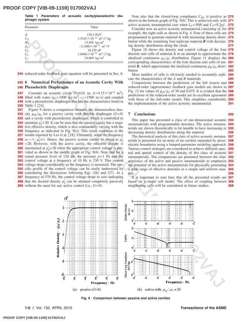
Figure 9 shows a comparison between the dimensionless den-sity �eff /�o for a passive cavity with flexible diaphragm �G=0�and a cavity with piezoelectric diaphragm, which is controlled tomaintain �d�=20. It can be seen that the passive cavity has a nega-tive effective density, which is also continuously varying with thefrequency as indicated in Fig. 9�a�. This result conforms to theresults reported by Lee et al. �18�. Ultimately, when the frequency�→�, �d�=1. Hence, the passive system cannot be tuned to �d�=20. However, with the active cavity, the effective density ismaintained at �d�=20 when the appropriate control voltage is pro-vided as shown in the middle graph of Fig. 9�b�. Note that for asound pressure level of 120 dB, the pressure p=1 Pa and thecontrol voltage at a frequency of 10 Hz is 230 V. This controlvoltage drops considerably as the frequency is increased. The spe-cific profile of the control voltage can be easily understood byconsidering the discussions following Eqs. �26� and �27�. At afrequency of 570 Hz, the control voltage drops to zero indicatingthat the desired density �d� can be attained completely passivelywithout the need for any active control �i.e., G=0�.
Note also that the closed-loop compliance CDC is positive asshown in the bottom graph of Fig. 9�b�. This is achieved only withactive acoustic metamaterial case when LP=50H and CS=0.2pf .
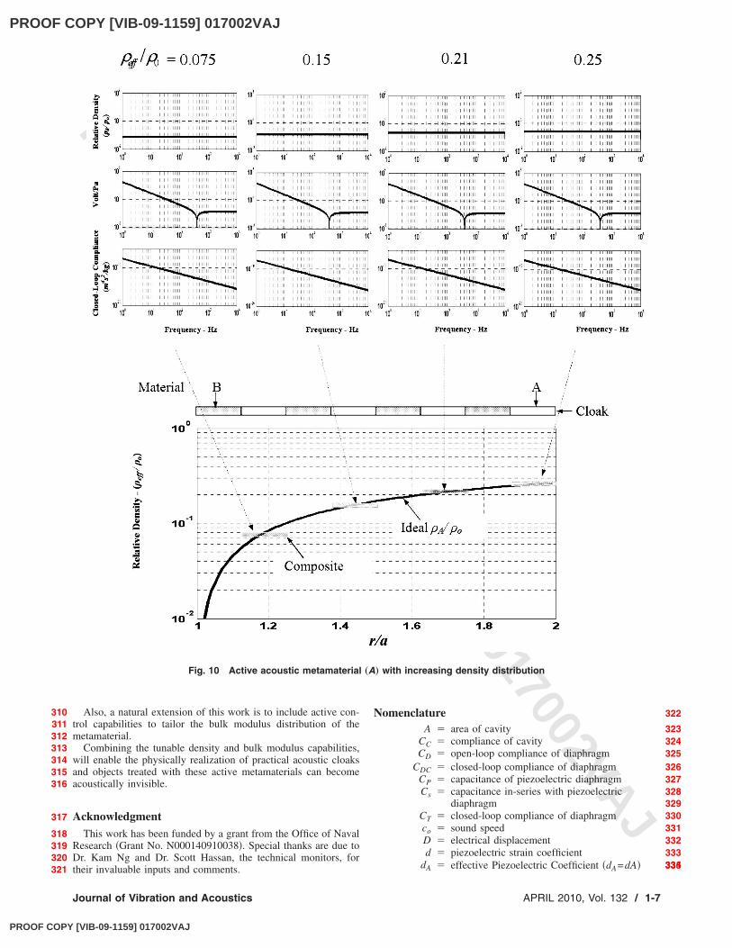
Consider now an active acoustic metamaterial consisting of, forexample, the eight cells as shown in Fig. 4. Four of these cells areprogrammed to generate material A with increasing density distri-bution while the remaining four replicate material B with decreas-ing density distribution along the cloak.
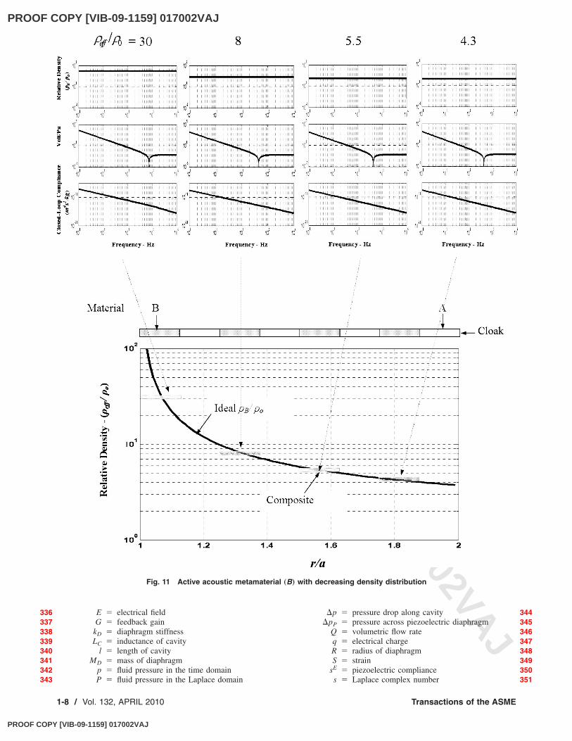
Figure 10 shows the density and control voltage of the fourdiscrete unit cells of material A in an attempt to approximate theidealized continuous �A /�o distribution. Figure 11 displays thecorresponding characteristics of the four discrete unit cells of ma-terial B, which approximate the idealized continuous �B /�o distri-bution.
More number of cells is obviously needed to accurately repli-cate the characteristics of the A and B materials.
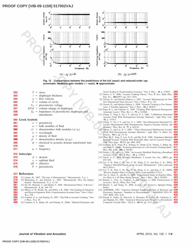
Comparisons between the predictions of the full �exact� andreduced-order �approximate� feedback gain models are shown inFig. 12 for values of �eff /�o of 30 and 0.075. It is evident that thepredictions of the reduced-order model are in excellent agreementwith those of the full-order model. This simplifies considerablythe implementation of the active acoustic metamaterial.
7 ConclusionsThis paper has presented a class of one-dimensional acoustic
metamaterials with programmable densities. The active metama-terials are shown theoretically to be tunable to have increasing ordecreasing density distributions along the material.
The theoretical analysis of this class of active acoustic metama-terials is presented for an array of air cavities separated by piezo-electric boundaries using a lumped-parameter modeling approach.Various control strategies are considered to achieve different spec-tral and spatial control of the density of this class of acousticmetamaterials. The comparisons are presented between the char-acteristics of the active and passive metamaterials to emphasizethe potential of the active metamaterials for physically generatinga wide range of effective densities in a simple and uniform man-ner.
It is important to note here that all the presented results arebased on a single cell model. The effect of coupling betweenneighboring cells will be considered in future studies.
Table 1 Parameters of acoustic cavity/piezoelectric dia-phragm system
Parameter Value
� 138.3 Pa/VCD 1.524310−13 m4 s2 /kgMD 13,456 kg /m4
dA −2.108010−11 m3 /VCP 18.239 nFCC 1.846610−15 m4 s2 /kgLC 24,069 kg /m4
Fig. 9 Comparison between passive and active cavities
244
245
246
247248249250251252253254255256257258259260261262263264265266267268269
270271272273274275276277278279280281282283284285286287288289290291
292
293294295296297298299300301302303304305306307308309
1-6 / Vol. 132, APRIL 2010 Transactions of the ASME
PROOF COPY [VIB-09-1159] 017002VAJ
PROOF COPY [VIB-09-1159] 017002VAJ
PROO
F COPY [VIB-09-1159] 017002VAJ
Also, a natural extension of this work is to include active con-trol capabilities to tailor the bulk modulus distribution of themetamaterial.
Combining the tunable density and bulk modulus capabilities,will enable the physically realization of practical acoustic cloaksand objects treated with these active metamaterials can becomeacoustically invisible.
AcknowledgmentThis work has been funded by a grant from the Office of Naval
Research �Grant No. N000140910038�. Special thanks are due toDr. Kam Ng and Dr. Scott Hassan, the technical monitors, fortheir invaluable inputs and comments.
NomenclatureA � area of cavity
CC � compliance of cavityCD � open-loop compliance of diaphragm
CDC � closed-loop compliance of diaphragmCP � capacitance of piezoelectric diaphragmCs � capacitance in-series with piezoelectric
diaphragmCT � closed-loop compliance of diaphragmco � sound speedD � electrical displacementd � piezoelectric strain coefficient
dA � effective Piezoelectric Coefficient �dA=dA�
Fig. 10 Active acoustic metamaterial „A… with increasing density distribution
310311312313314315316
317
318319320321
322
323324325326327328329330331332333334335
Journal of Vibration and Acoustics APRIL 2010, Vol. 132 / 1-7
PROOF COPY [VIB-09-1159] 017002VAJ
PROOF COPY [VIB-09-1159] 017002VAJ
PROO
F COPY [VIB-09-1159] 017002VAJ
E � electrical fieldG � feedback gain
kD � diaphragm stiffnessLC � inductance of cavity
l � length of cavityMD � mass of diaphragm
p � fluid pressure in the time domainP � fluid pressure in the Laplace domain
�p � pressure drop along cavity�pP � pressure across piezoelectric diaphragm
Q � volumetric flow rateq � electrical chargeR � radius of diaphragmS � strain
sE � piezoelectric compliances � Laplace complex number
Fig. 11 Active acoustic metamaterial „B… with decreasing density distribution
336337338339340341342343
344345346347348349350351
1-8 / Vol. 132, APRIL 2010 Transactions of the ASME
PROOF COPY [VIB-09-1159] 017002VAJ
PROOF COPY [VIB-09-1159] 017002VAJ
PROO
F COPY [VIB-09-1159] 017002VAJ
T � stresst � diaphragm thicknessu � flow velocityV � volume of cavity
VP � piezoelectric voltage�Vol � volume change of diaphragm
ZP � Impedance of piezoelectric diaphragm andattachments
Greek Symbols� � permittivity� � bulk modulus of fluid
�� � dimensionless bulk modulus �� /�o�� � wavelength� � density of fluid
�� � dimensionless density �� /�o�� � electrical to acoustic domain transformer turn
ratio� � frequency
Subscriptsd � desiredo � ambient fluid
eff � effectiveP � piezoelectric
References�1� Lapine, M., 2007, “The Age of Metamaterials,” Metamaterials, 1, p. 1.�2� Shamonina, E., and Solymar, L., 2007, “Metamaterials: How the Subject
Started,” Metamaterials, 1, p. 12–18.�3� Gil, M., Bonache, J., and Martín, F., 2008, “Metamaterial Filters: A Review,”
Metamaterials, 2, pp. 186–197.�4� Milton, G. W., Briane, M., and Willis, J. R., 2006, “On Cloaking for Elasticity
and Physical Equations With a Transformation Invariant Form,” New J. Phys.,8, p. 248.
�5� Cummer, S. A., and Schurig, D., 2007, “One Path to Acoustic Cloaking,” NewJ. Phys., 9, p. 45.
�6� Cummer, S. A., Rahm, M., and Schurig, D., 2008a, “Material Parameters and
Vector Scaling in Transformation Acoustics,” New J. Phys., 10, p. 115025.�7� Norris, A. N., 2008, “Acoustic Cloaking Theory,” Proc. R. Soc., Math. Phys.
Eng. Sci., 464�2097�, pp. 2411–2434.�8� Torrent, D., and Sánchez-Dehesa, J., 2007, “Acoustic Metamaterials for New
Two Dimensional Sonic Devices,” New J. Phys., 9, p. 323.�9� Torrent, D., and Sánchez-Dehesa, J., 2008, “Acoustic Cloaking in Two Dimen-
sions: A Feasible Approach,” New J. Phys., 10, p. 063015.�10� Popa, B. I., and Cummer, S., 2009, “Cloaking With Optimized Homogenous
Anistropic Layers,” Phys. Rev. A, 79, p. 023806.�11� Cheng, Y., Yang, F., Xu, J. Y., and Liu, X. J., 2008, “A Multilayer Structured
Acoustic Cloak With Homogeneous Isotropic Materials,” Appl. Phys. Lett.,92, p. 151913.
�12� Cheng, Y., Xu, J. Y., and Liu, X. J., 2008, “One-Dimensional Structured Ul-trasonic Metamaterials With Simultaneously Negative Dynamic Density andModulus,” Phys. Rev. B, 77, p. 045134.
�13� Cheng, Y., and Liu, X. J., 2009, ““Three Dimensional Multilayered AcousticCloak With Homogeneous Isotropic Materials,” Appl. Phys. A: Mater. Sci.Process., 94�1�, pp. 25–30.
�14� Chen, H.-Y., Yang, T., Luo, X.-D., and Ma, H.-R., 2008, “Impedance-MatchedReduced Acoustic Cloaking With Realizable Mass and Its Layered Design,”Chin. Phys. Lett., 25�10�, pp. 3696–3699.
�15� Cummer, S. A., Popa, B.-I., Schurig, D., Smith, D. R., Pendry, J., Rahm, M.,and Starr, A., 2008b, “Scattering Derivation of a 3D Acoustic Cloaking Shell,”Phys. Rev. Lett., 100, p. 024301.
�16� Pendry, J. B., and Li, J., 2008, “An Acoustic Metafluid: Realizing a BroadbandAcoustic Cloak,” New J. Phys., 10, p. 115032.
�17� Norris, A. N., 2009, “Acoustic Metafluids,” J. Acoust. Soc. Am., 125�2�, pp.839–849.
�18� Lee, S. H., Park, C. M., Seo, Y. M., Wang, Z. G., and Kim, C. K., 2009a,“Negative Effective Density in an Acoustic Metamaterial,” arXiv:cond-mat/0812.2954v3.
�19� Lee, S. H., Park, C. M., Seo, Y. M., Wang, Z. G., and Kim, C. K., 2009b,“Reverse Doppler Effect of Sound,” arXiv:cond-mat/0901.2772v2.
�20� Yao, S., Zhou, X., and Hu, G., 2008, “Experimental Study on Negative Effec-tive Mass in a 1D Mass–Spring System,” New J. Phys., 10, p. 043020.
�21� Kinsler, L., Frey, A., Coppens, A., and Sanders, J., 2000, Fundamentals ofAcoustics, 4th ed., Wiley, New York.
�22� Blauert, J., and Xiang, N., 2008, Acoustics for Engineers, Springer-Verlag,Berlin.
�23� ANSI/IEEE, 1987, “American National Standards/Institute of Electrical andElectronics Engineers “Standard on Piezoelectricity”,” ANSI/IEEE STD:176-1987, IEEE, New York.
�24� Prasad, S., Gallas, Q., Horowitz, S., Homeijer, B., Sankar, B., Cattafesta, L.,and Sheplak, M., 2006, “Analytical Electroacoustic Model of a PiezoelectricComposite Circular Plate,” AIAA J., 44�10�, pp. 2311–2318.
Fig. 12 Comparisons between the predictions of the full „exact… and reduced-order „ap-proximate… feedback gain models „— exact, � approximate…
352353354355356357358359
360361362363364365366367368369370371
372373374375376
377378379380381382383384385386387388
389390391392393394395396397398399400401402403404405406407408409410411412413414415416417418419420421422423424425426427428429430431432433
Journal of Vibration and Acoustics APRIL 2010, Vol. 132 / 1-9
PROOF COPY [VIB-09-1159] 017002VAJ