an adaptive control strategy for dstatcom...
TRANSCRIPT
Copyright (c) 2009 IEEE. Personal use is permitted. For any other purposes, Permission must be obtained from the IEEE by emailing [email protected].
This article has been accepted for publication in a future issue of this journal, but has not been fully edited. Content may change prior to final publication.
1
Abstract— Distribution Static Compensator (DSTATCOM) is a shunt compensation device which is generally used to solve power quality
problems in distribution systems. In an all-electric ship power system, power quality issues arise due to high energy demand loads such as
pulse loads. This paper presents the application of a DSTATCOM to improve the power quality in a ship power system during and after pulse
loads. The control strategy of the DSTATCOM plays an important role in maintaining the voltage at the point of common coupling. A novel
adaptive control strategy for the DSTATCOM based on Artificial Immune System (AIS) is presented in this paper. The optimal parameters of
the controller are obtained first using the particle swarm optimization algorithm. This provides a sort of innate immunity (robustness) to
common system disturbances. For unknown and random system disturbances, the controller parameters are modified online, thus providing
adaptive immunity to the control system. The performance of the DSTATCOM and the AIS based adaptive control strategy is investigated first
in MATLAB/SIMULINK based simulation platform. It is verified through a real-time ship power system implementation on a Real-Time
Digital Simulator (RTDS) and the control algorithm on a digital signal processor (DSP).
Index Terms— Adaptive control, adaptive immunity, artificial immune system, DSP, DSTATCOM, electric ship power system, innate
immunity, RTDS.
An Adaptive Control Strategy for DSTATCOM
Applications in an Electric Ship Power System
Pinaki Mitra, Student Member, IEEE, and Ganesh K. Venayagamoorthy, Senior Member, IEEE
Authorized licensed use limited to: Missouri University of Science and Technology. Downloaded on January 24, 2010 at 16:01 from IEEE Xplore. Restrictions apply.
Copyright (c) 2009 IEEE. Personal use is permitted. For any other purposes, Permission must be obtained from the IEEE by emailing [email protected].
This article has been accepted for publication in a future issue of this journal, but has not been fully edited. Content may change prior to final publication.
2
I. INTRODUCTION
HE power system of an all-electric navy ship has an integrated network, where the propulsion load, the distribution loads,
sensor and other emergency loads and pulse loads (rail guns, aircraft launchers, etc.) – all are part of the same electrical
network. Among the loads, the effects of pulse loads are most detrimental for the power quality of ship power distribution
system as they require a very high amount of energy for a very short period of time [1], [2]. In order to improve the survivability
of a navy ship in battle conditions, a distribution static compensator (DSTATCOM) can be used to reduce the impact of pulse
loads on the bus voltage and thus keep it at desired level. DSTATCOM is a voltage-source inverter (VSI) based shunt device [3]
generally used in distribution system to improve power quality. The main advantage of DSTATCOM is that, the current
injection into the distribution bus can be regulated very efficiently by the sophisticated power electronics based control present
in it. Another advantage is that, it has multifarious applications, e.g. it can be used for canceling the effect of poor load power
factor, for suppressing the effect of harmonic content in load currents, for regulating the voltage of distribution bus against
sag/swell etc. and also for compensating the reactive power requirement of the load and so on [4]. In this paper, the application
of DSTATCOM to regulate voltage at the point of common coupling (PCC) is presented.
The internal controls of a DSTATCOM play a very important role in the effectiveness of the DSTATCOM in maintaining the
PCC voltage during pulse loads. Most of the research in DSTATCOM has focused on topology and its applications. For
example, different control strategies based on the respective multi-level inverter topologies of shunt compensators are discussed
in [3] and also in [5]-[7]. A robust controller, sliding mode control strategy, is adopted in [8] and [9]. But, these control
strategies are not adaptive to changes in the system dynamics and hence the performance may not be satisfactory for unknown
and random system disturbances. These types of disturbances are inevitable in naval shipboard systems, especially in battle
conditions. Different ranges of rail guns and launchers may be used leading to a wide variation of pulse power disturbances.
Adaptive control of a DSTATCOM becomes essential for survivability. Conventional controllers for DSTATCOMs are mainly
based on PI controllers. The tuning of PI controllers is a complex task for a nonlinear system with lot of switching devices. In
order to overcome these problems, Computational intelligence (CI) techniques can be used. Application of CI techniques in
designing adaptive controller for DSTATCOM is not yet explored that much by the researchers. References [10] and [11] are
based on neural networks (NNs). In [10], the PI controllers are replaced by a NN trained with the backpropagation algorithm.
But, the training is carried out offline and hence the ANN based controller is not adaptive. In [11], a NN based reference current
generator is used, which is a partially adaptive control strategy. Here, though the reference generator adapts its NN weights
online, but the DC voltage regulation is handled by conventional PI controllers.
In this paper, a new adaptive control strategy for a DSTATCOM based on Artificial Immune System (AIS) is presented. Most
of the CI techniques are offline and require prior knowledge of the system behavior. But AIS, which is inspired by theoretical
immunology and observed immune functions, principles and models, has the potential for online adaptive system identification
and control [12]. Abnormal changes in the system response are identified and acted upon without having any prior knowledge
[13]. The AIS based DSTATCOM controller exhibits innate and adaptive immune system behaviors. Innate response is for
common disturbances and requires controller parameters to be optimal. In this paper, the innate controller parameters are
determined using the particle swarm optimization algorithm. The adaptive response is for new and unusual disturbances, and
requires the controller parameters to be adaptive. The AIS strategy is applied in this paper for adaptation of these parameters.
T
Authorized licensed use limited to: Missouri University of Science and Technology. Downloaded on January 24, 2010 at 16:01 from IEEE Xplore. Restrictions apply.
Copyright (c) 2009 IEEE. Personal use is permitted. For any other purposes, Permission must be obtained from the IEEE by emailing [email protected].
This article has been accepted for publication in a future issue of this journal, but has not been fully edited. Content may change prior to final publication.
3
The adaptive control strategy for a DSTATCOM in a shipboard power system is first investigated in the MATLAB/Simulink
based simulation environment [14]. Based on the satisfactory performance, it is then implemented on a platform consisting of a
Real-Time Digital Simulator (RTDS) and a digital signal processor (DSP). The advantage of RTDS is that, it can represent the
dynamics of a system close as a practical system. The fast acting power electronic switching devices are also simulated in such a
way that it can be interfaced with a practical hardware system any time. The tuning of the controller parameters using particle
swarm optimization (PSO), to exhibit innate response, as well as the AIS based control strategy, to exhibit adaptive response, are
implemented on a DSP interfaced to the RTDS.
II. DSTATCOM AND ITS CONTROL STRUCTURE
The simplest structure of a DSTATCOM is shown in Fig. 1. The principle of operation of DSTATCOM is based on the fact
that the real and reactive power can be varied by the voltage magnitude (VC) of the inverter and the angle difference between the
bus and the inverter output (α). The active and reactive power are expressed as follows:
sinV VPCC CP
X
(1)
( cos )PCC PCC C
V V VQ
X
(2)
Where
P = Active power,
Q = Reactive power,
VC = Inverter voltage,
VPCC = Voltage at the PCC,
α = Angle of VPCC with respect to VC and
X = Reactance of the branch and the transformer.
In steady state operation, the angle α is very close to zero. Now, if VPCC < VC, reactive power flows from the DSTATCOM to
the bus. So, by controlling the inverter voltage magnitude VC, the reactive power flow from the DSTATCOM can be regulated.
This can be done in several ways. In this paper, two different types of control strategies for DSTATCOM are considered.
VD
C
DCCFL FR
CV 00PCCV
VD
C
DCCFL FR
CV 00PCCV
Fig. 1. Schematic diagram of DSTATCOM
The first type of control strategy is employed for the MATLAB based simulation. Here, a GTO based square wave voltage
source converter (VSC) is used to generate the alternating voltage from the DC bus. In this type of inverters, the fundamental
component of the inverter output voltage is proportional to the DC bus voltage. So, the control objective is to regulate VDC as per
requirement. Also, the phase angle should be maintained so that the AC generated voltage is in phase with the bus voltage. The
Authorized licensed use limited to: Missouri University of Science and Technology. Downloaded on January 24, 2010 at 16:01 from IEEE Xplore. Restrictions apply.
Copyright (c) 2009 IEEE. Personal use is permitted. For any other purposes, Permission must be obtained from the IEEE by emailing [email protected].
This article has been accepted for publication in a future issue of this journal, but has not been fully edited. Content may change prior to final publication.
4
schematic diagram of the control circuit is shown in Fig. 2.
Fig. 2. Control structure for the DSTATCOM for MATLAB implementation
Here, the PLL synchronizes the GTO pulses to the system voltage and generates a reference angle. This reference angle is
used to calculate positive sequence component of the DSTATCOM current using a-b-c to d-q-0 transformation. The voltage
regulator block calculates the difference between reference voltage and measured bus voltage and the output is passed through a
PI controller to generate the reactive current reference Iq_ref. This Iq_ref is then passed through a current regulator block to
generate the angle α. This current regulator block also consists of a PI controller to keep the angle α close to zero.
The ‗firing pulse generator‘ block generates square pulses for the inverter from the output of the PLL and the current regulator
block. If due to the application of a pulse load the bus voltage reduces to some extent, the voltage regulator changes the Iq_ref and
as a result the current regulator increases the angle α so that more active power flows from bus to the DSTATCOM and
energizes the capacitor. So the DC voltage increases and consequently the AC output of the inverter also increases and the
necessary reactive power flows from DSTATCOM to the bus.
The second type of control strategy consists of IGBT based inverter and is employed for the real-time implementation. It is
represented by Fig. 3.
Fig. 3. DSTATCOM control structure for an RTDS implementation
abc
to
dq0
PLL
PI(1)
PI(2) PI(4)
PI(3)
triangular
wave
generator
dq0
to
abc
sine
triangle
modulation
Vbus
Vd
Vq
Vabc
Vcap_ref
Vcap
Iabc
Id
Iq
Id_ref
Iq_refVbus_ref
Vbus
pulses
φ
+-
+-
+-
+-
-+
++
-+
L
L
abc
to
dq0
PLL
PI(1)
PI(2) PI(4)
PI(3)
triangular
wave
generator
dq0
to
abc
sine
triangle
modulation
Vbus
Vd
Vq
Vabc
Vcap_ref
Vcap
Iabc
Id
Iq
Id_ref
Iq_refVbus_ref
Vbus
pulses
φ
+-
+-
+-
+-
-+
++
-+
L
L
Authorized licensed use limited to: Missouri University of Science and Technology. Downloaded on January 24, 2010 at 16:01 from IEEE Xplore. Restrictions apply.
Copyright (c) 2009 IEEE. Personal use is permitted. For any other purposes, Permission must be obtained from the IEEE by emailing [email protected].
This article has been accepted for publication in a future issue of this journal, but has not been fully edited. Content may change prior to final publication.
5
Here, the PLL generates a reference angle. This reference angle is used to calculate d-q component of the DSTATCOM
current using a-b-c to d-q-0 transformation. Also this angle is used to calculate the a-b-c voltage from its d and q components
and to generate a triangular wave for the sine-triangle modulator to produce required firing pulses. The controller uses a two
layer decoupled control scheme to keep the bus voltage and the DC capacitor voltage at constant level [15]. The PI controllers of
the outer layer (PI(1) and PI(2)) generate the reference currents Id_ref and Iq_ref for the inner loop. The other two PI controllers
(PI(3) and PI(4)) just keeps track of the reference.
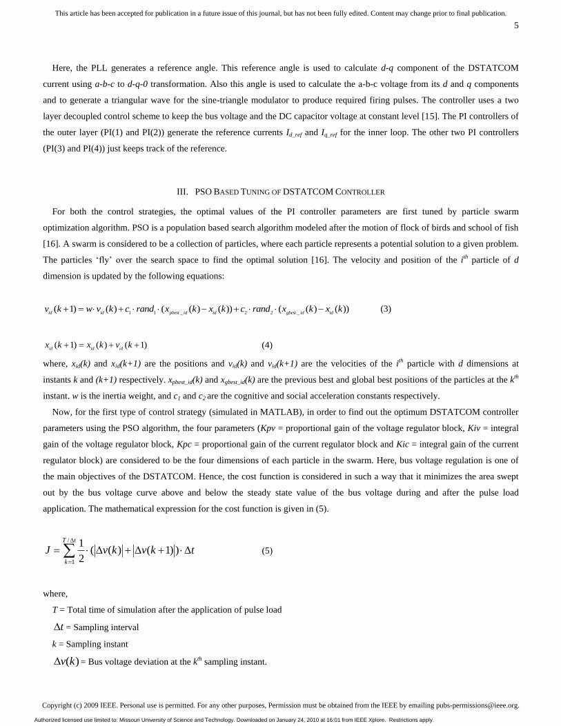
III. PSO BASED TUNING OF DSTATCOM CONTROLLER
For both the control strategies, the optimal values of the PI controller parameters are first tuned by particle swarm
optimization algorithm. PSO is a population based search algorithm modeled after the motion of flock of birds and school of fish
[16]. A swarm is considered to be a collection of particles, where each particle represents a potential solution to a given problem.
The particles ‗fly‘ over the search space to find the optimal solution [16]. The velocity and position of the ith particle of d
dimension is updated by the following equations:
1 1 _ 2 2 _( 1) ( ) ( ( ) ( )) ( ( ) ( ))
id id pbest id id gbest id idv k w v k c rand x k x k c rand x k x k (3)
( 1) ( ) ( 1)id id id
x k x k v k (4)
where, xid(k) and xid(k+1) are the positions and vid(k) and vid(k+1) are the velocities of the ith particle with d dimensions at
instants k and (k+1) respectively. xpbest_id(k) and xgbest_id(k) are the previous best and global best positions of the particles at the kth
instant. w is the inertia weight, and c1 and c2 are the cognitive and social acceleration constants respectively.
Now, for the first type of control strategy (simulated in MATLAB), in order to find out the optimum DSTATCOM controller
parameters using the PSO algorithm, the four parameters (Kpv = proportional gain of the voltage regulator block, Kiv = integral
gain of the voltage regulator block, Kpc = proportional gain of the current regulator block and Kic = integral gain of the current
regulator block) are considered to be the four dimensions of each particle in the swarm. Here, bus voltage regulation is one of
the main objectives of the DSTATCOM. Hence, the cost function is considered in such a way that it minimizes the area swept
out by the bus voltage curve above and below the steady state value of the bus voltage during and after the pulse load
application. The mathematical expression for the cost function is given in (5).
/
1
1( ( ) ( 1) )
2
T t
k
J v k v k t
(5)
where,
T = Total time of simulation after the application of pulse load
t = Sampling interval
k = Sampling instant
( )v k = Bus voltage deviation at the kth sampling instant.
Authorized licensed use limited to: Missouri University of Science and Technology. Downloaded on January 24, 2010 at 16:01 from IEEE Xplore. Restrictions apply.

Copyright (c) 2009 IEEE. Personal use is permitted. For any other purposes, Permission must be obtained from the IEEE by emailing [email protected].
This article has been accepted for publication in a future issue of this journal, but has not been fully edited. Content may change prior to final publication.
6
To have a fast PSO search performance, the values of w, c1 and c2 are kept fixed at 0.8, 2.0 and 2.0 respectively and the
number of particles taken is 25 [16]. The optimum PI controller parameters found by PSO are Kpv = 20.0, Kiv = 1462.5, Kpc =
20.2 and Kic = 35.1.
For the second type of control strategy which is implemented on the RTDS, a real-time PSO based tuning of controller
parameters is implemented. In this type of control, the performance of a DSTATCOM strongly depends on the PI controllers of
the external loop which generate the current references. Hence, in this paper, those two PI controllers, (PI(1) and PI(2)) in Fig. 3,
are tuned using PSO. The PSO algorithm is implemented on an Innovative Integration M67 card, which is based on the Texas
Instruments TMS3206701 DSP. The M67 operates at 160 MHz and is equipped with two A/D conversion and D/A conversion
modules. The rest of the system is built in RSCAD software, which is an integrated part of RTDS. The analog signal provided to
the M67 is the AC bus voltage deviation ( ( )v k ), which comes from the RTDS. This is converted to digital signal through the
A/D block of the DSP and is used to calculate the fitness value of the controller parameters. The cost function is considered to be
the same as (5). The four parameters (Kp1 = proportional gain of PI(1), Ki1 = integral gain of PI(1), Kp2 = proportional gain of
PI(2), Ki2 = integral gain of PI(2)) are the dimensions of each particle of the swarm. The particle positions are initiated randomly
inside the DSP and are sent to the RTDS as analog voltage signals within the range of -10 to +10 Volts. These voltages are
scaled proportionately inside the RTDS and used as the PI controller parameters for each iteration. The calculation of pbest and
gbest, the update of position and velocity, are all performed by the DSP. The laboratory hardware setup for this study is shown
in Fig. 4. The optimum PI controller parameters found by PSO are Kp1 = 30.0, Ki1 = 50.02, Kp2 = 124.7 andKi2 = 2.08.
RTDS
DSP-RTDS Interface
Remote Workstation
(Draft and Runtime File)
Download
M67 DSP Card
Host PC
RTDS
Remote Workstation
(Draft and Runtime File)
Download
M67 DSP Card
Host PC
Fig. 4. Laboratory hardware setup including RTDS and DSP
IV. BIOLOGICAL IMMUNE SYSTEM AND ADAPTIVE CONTROLLER DESIGN
The natural immune system of a human body is basically the interaction of various cells. Among these, T and B cells play the
most vital roles. B cells secrete antibodies, whereas, T cells are made of three types of cells: a) helper T cells, b) suppressor T
cells, c) killer T cells. Within the immune system, there is a feedback mechanism. When a non-self cell (antigen) is identified in
Authorized licensed use limited to: Missouri University of Science and Technology. Downloaded on January 24, 2010 at 16:01 from IEEE Xplore. Restrictions apply.

Copyright (c) 2009 IEEE. Personal use is permitted. For any other purposes, Permission must be obtained from the IEEE by emailing [email protected].
This article has been accepted for publication in a future issue of this journal, but has not been fully edited. Content may change prior to final publication.
7
a human body by APC (Antigen Presenting Cell), it activates helper T cells. Those helper T cells then stimulate the B cells, the
killer T cells and the suppressor T cells. Activation of B cell is the most important feedback mechanism of the immune system
and it is basically responsible for elimination of antigens. Again, when the number of antigens is reduced, the suppressor T cells
inhibit the activities of all other cells. As a result of this inhibitive feedback mechanism, the action of immune system is
tranquilized [12].
The approach to adapt parameters of the two PI controllers, which are already found by PSO for innate immunity, is described
below. The discussion is presented with reference to the second control strategy which is implemented on the RTDS. A similar
approach is also followed for the MATLAB based test system. In order to avoid repetition, it is not discussed separately.
The amount of foreign material (antigen) at kth generation is defined here as the deviation in the PCC bus voltage ( )bV k and
also the deviation of the capacitor voltage ( )CAPV k . The first PI controller‘s (PI(1)) objective is to maintain the capacitor
voltage constant, i.e. ( )CAPV k should be zero. Similarly, the other PI controller, (PI(2)), should keep ( )bV k equal to zero. In
terms of AIS, the aforesaid functions of the PI controllers can be made adaptive considering the actions of the helper and
suppressor T cells. The mathematical representation shown here is only for the antigen ( )bV k . The same analysis holds for the
antigen ( )CAPV k .
The output from the helper T cells stimulated by the antigen ( )bV k is given by
( ) ( )bTH k m V k (6)
where ‗m‘ is the stimulation factor whose sign is positive. The suppressor T cells inhibit the other cell activities and its effect can
be represented by
' ( )( ) ( )
( 1)
bb
b
V kTS k m f V k
V k
(7)
where m’ is positive suppression factor. f(x) is a non-linear function which is defined as
2( ) exp( )f x x (8)
The output of the function is limited within the interval [0, 1]. The total stimulation received by the B cells is based on
immune based feedback law which is given by
'
( ) ( ) ( )
( )( ) ( )
( 1)
bb
b
B k TH k TS k
V kB k m m f V k
V k
(9)
So, the mechanism basically consists of two actions: once the antigens are found, the TH cells work to eliminate them,
whereas the TS cells work to inhibit the actions of other cells. Fig. 5 illustrates this action of immune based adaptive controller
for the disturbance ( )bV k , where the parameters for the second PI controller (PI(2)) are modified online based on AIS. A
similar figure can be drawn for the disturbance ( )CAPV k , which dynamically modifies the parameters associated with the first
PI controller (PI(1)).
In this paper, for the real-time implementation, the AIS based control strategy is implemented on a DSP. Each AIS based PI
controller is associated with four ‗m‘ constants as shown in Fig. 5. So there are as a whole eight ‘m’ constants (m1 to m8),
stimulation and suppression, for two PI controllers which are first tuned using PSO. The optimal values of these eight ‘m’
Authorized licensed use limited to: Missouri University of Science and Technology. Downloaded on January 24, 2010 at 16:01 from IEEE Xplore. Restrictions apply.
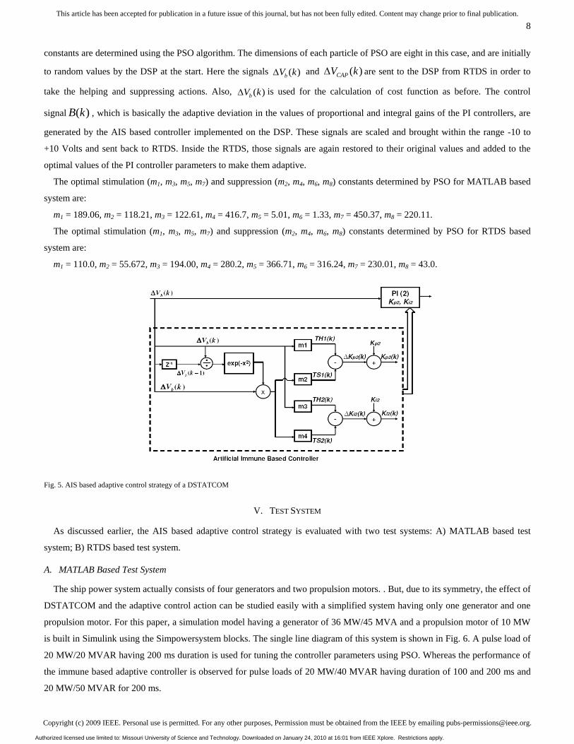
Copyright (c) 2009 IEEE. Personal use is permitted. For any other purposes, Permission must be obtained from the IEEE by emailing [email protected].
This article has been accepted for publication in a future issue of this journal, but has not been fully edited. Content may change prior to final publication.
8
constants are determined using the PSO algorithm. The dimensions of each particle of PSO are eight in this case, and are initially
to random values by the DSP at the start. Here the signals ( )bV k and ( )CAPV k are sent to the DSP from RTDS in order to
take the helping and suppressing actions. Also, ( )bV k is used for the calculation of cost function as before. The control
signal ( )B k , which is basically the adaptive deviation in the values of proportional and integral gains of the PI controllers, are
generated by the AIS based controller implemented on the DSP. These signals are scaled and brought within the range -10 to
+10 Volts and sent back to RTDS. Inside the RTDS, those signals are again restored to their original values and added to the
optimal values of the PI controller parameters to make them adaptive.
The optimal stimulation (m1, m3, m5, m7) and suppression (m2, m4, m6, m8) constants determined by PSO for MATLAB based
system are:
m1 = 189.06, m2 = 118.21, m3 = 122.61, m4 = 416.7, m5 = 5.01, m6 = 1.33, m7 = 450.37, m8 = 220.11.
The optimal stimulation (m1, m3, m5, m7) and suppression (m2, m4, m6, m8) constants determined by PSO for RTDS based
system are:
m1 = 110.0, m2 = 55.672, m3 = 194.00, m4 = 280.2, m5 = 366.71, m6 = 316.24, m7 = 230.01, m8 = 43.0.
Fig. 5. AIS based adaptive control strategy of a DSTATCOM
V. TEST SYSTEM
As discussed earlier, the AIS based adaptive control strategy is evaluated with two test systems: A) MATLAB based test
system; B) RTDS based test system.
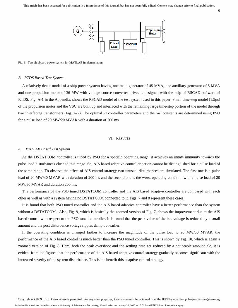
A. MATLAB Based Test System
The ship power system actually consists of four generators and two propulsion motors. . But, due to its symmetry, the effect of
DSTATCOM and the adaptive control action can be studied easily with a simplified system having only one generator and one
propulsion motor. For this paper, a simulation model having a generator of 36 MW/45 MVA and a propulsion motor of 10 MW
is built in Simulink using the Simpowersystem blocks. The single line diagram of this system is shown in Fig. 6. A pulse load of
20 MW/20 MVAR having 200 ms duration is used for tuning the controller parameters using PSO. Whereas the performance of
the immune based adaptive controller is observed for pulse loads of 20 MW/40 MVAR having duration of 100 and 200 ms and
20 MW/50 MVAR for 200 ms.
Authorized licensed use limited to: Missouri University of Science and Technology. Downloaded on January 24, 2010 at 16:01 from IEEE Xplore. Restrictions apply.
Copyright (c) 2009 IEEE. Personal use is permitted. For any other purposes, Permission must be obtained from the IEEE by emailing [email protected].
This article has been accepted for publication in a future issue of this journal, but has not been fully edited. Content may change prior to final publication.
9
Fig. 6. Test shipboard power system for MATLAB implementation
B. RTDS Based Test System
A relatively detail model of a ship power system having one main generator of 45 MVA, one auxiliary generator of 5 MVA
and one propulsion motor of 36 MW with voltage source converter drives is designed with the help of RSCAD software of
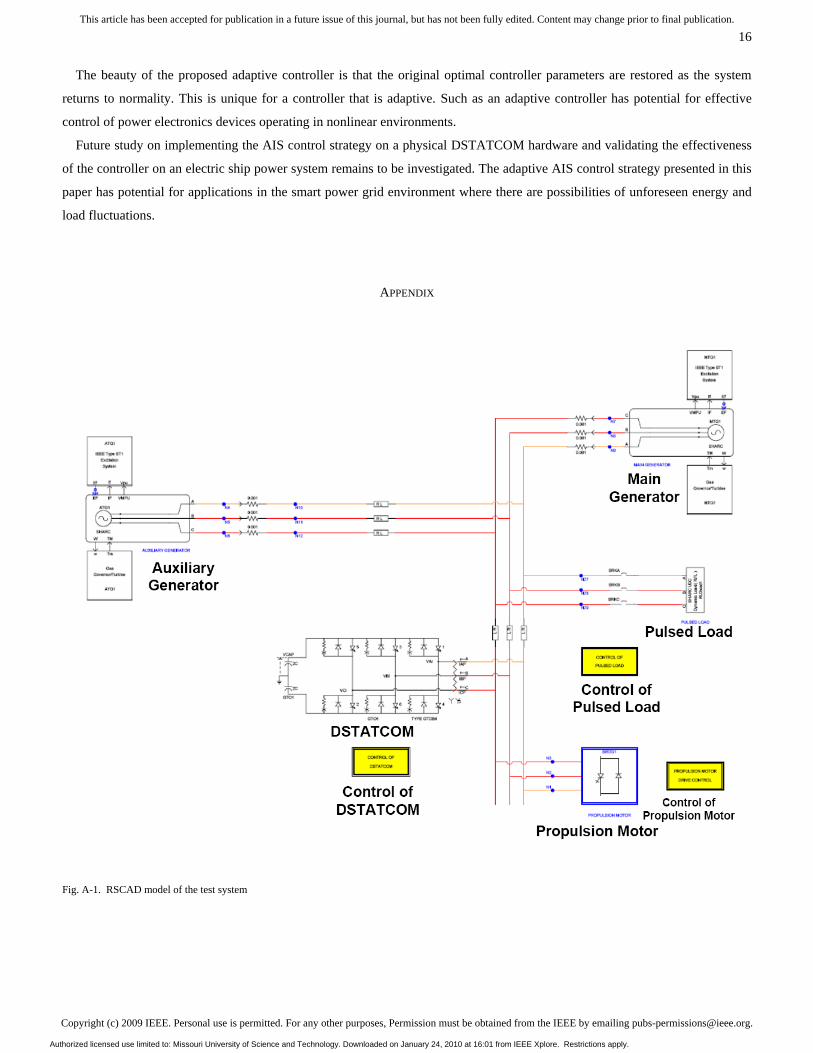
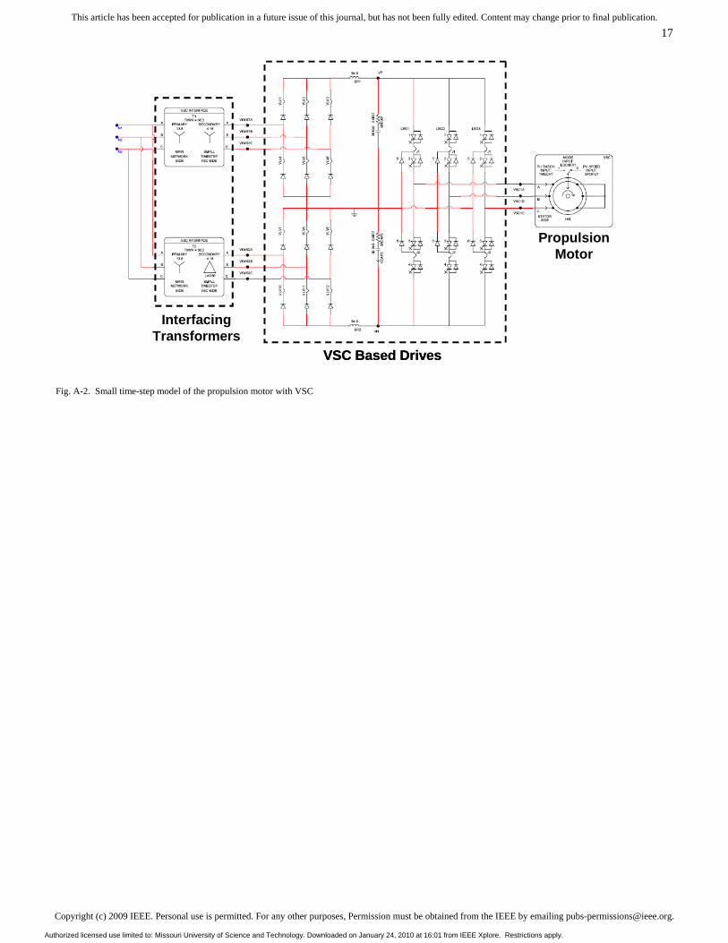
RTDS. Fig. A-1 in the Appendix, shows the RSCAD model of the test system used in this paper. Small time-step model (1.5μs)
of the propulsion motor and the VSC are built up and interfaced with the remaining large time-step portion of the model through
two interfacing transformers (Fig. A-2). The optimal PI controller parameters and the ‘m’ constants are determined using PSO
for a pulse load of 20 MW/20 MVAR with a duration of 200 ms.
VI. RESULTS
A. MATLAB Based Test System
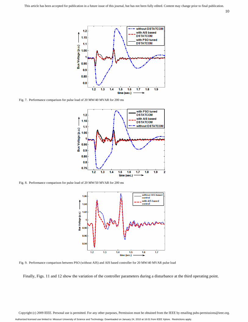
As the DSTATCOM controller is tuned by PSO for a specific operating range, it achieves an innate immunity towards the
pulse load disturbances close to this range. So, AIS based adaptive controller action cannot be distinguished for a pulse load of
the same range. To observe the effect of AIS control strategy two unusual disturbances are simulated. The first one is a pulse
load of 20 MW/40 MVAR with duration of 200 ms and the second one is the worst operating condition with a pulse load of 20
MW/50 MVAR and duration 200 ms.
The performance of the PSO tuned DSTATCOM controller and the AIS based adaptive controller are compared with each
other as well as with a system having no DSTATCOM connected to it. Figs. 7 and 8 represent these cases.
It is found that both PSO tuned controller and the AIS based adaptive controller have a better performance than the system
without a DSTATCOM. Also, Fig. 9, which is basically the zoomed version of Fig. 7, shows the improvement due to the AIS
based control with respect to the PSO tuned controller. It is found that the peak value of the bus voltage is reduced by a small
amount and the post disturbance voltage ripples damp out earlier.
If the operating condition is changed farther to increase the magnitude of the pulse load to 20 MW/50 MVAR, the
performance of the AIS based control is much better than the PSO tuned controller. This is shown by Fig. 10, which is again a
zoomed version of Fig. 8. Here, both the peak overshoot and the settling time are reduced by a noticeable amount. So, it is
evident from the figures that the performance of the AIS based adaptive control strategy gradually becomes significant with the
increased severity of the system disturbance. This is the benefit this adaptive control strategy.
Authorized licensed use limited to: Missouri University of Science and Technology. Downloaded on January 24, 2010 at 16:01 from IEEE Xplore. Restrictions apply.
Copyright (c) 2009 IEEE. Personal use is permitted. For any other purposes, Permission must be obtained from the IEEE by emailing [email protected].
This article has been accepted for publication in a future issue of this journal, but has not been fully edited. Content may change prior to final publication.
10
Fig. 7. Performance comparison for pulse load of 20 MW/40 MVAR for 200 ms
Fig. 8. Performance comparison for pulse load of 20 MW/50 MVAR for 200 ms
Fig. 9. Performance comparison between PSO (without AIS) and AIS based controller for 20 MW/40 MVAR pulse load
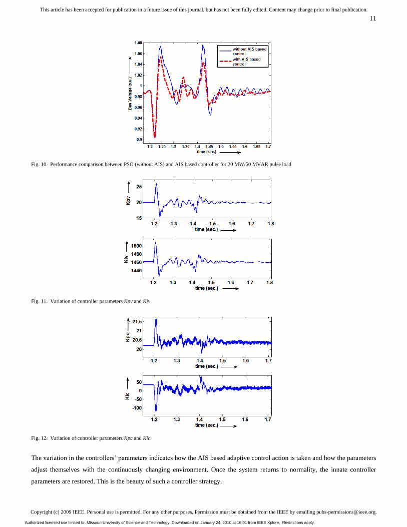
Finally, Figs. 11 and 12 show the variation of the controller parameters during a disturbance at the third operating point.
Authorized licensed use limited to: Missouri University of Science and Technology. Downloaded on January 24, 2010 at 16:01 from IEEE Xplore. Restrictions apply.
Copyright (c) 2009 IEEE. Personal use is permitted. For any other purposes, Permission must be obtained from the IEEE by emailing [email protected].
This article has been accepted for publication in a future issue of this journal, but has not been fully edited. Content may change prior to final publication.
11
Fig. 10. Performance comparison between PSO (without AIS) and AIS based controller for 20 MW/50 MVAR pulse load
Fig. 11. Variation of controller parameters Kpv and Kiv
Fig. 12. Variation of controller parameters Kpc and Kic
The variation in the controllers‘ parameters indicates how the AIS based adaptive control action is taken and how the parameters
adjust themselves with the continuously changing environment. Once the system returns to normality, the innate controller
parameters are restored. This is the beauty of such a controller strategy.
Authorized licensed use limited to: Missouri University of Science and Technology. Downloaded on January 24, 2010 at 16:01 from IEEE Xplore. Restrictions apply.
Copyright (c) 2009 IEEE. Personal use is permitted. For any other purposes, Permission must be obtained from the IEEE by emailing [email protected].
This article has been accepted for publication in a future issue of this journal, but has not been fully edited. Content may change prior to final publication.
12
B. RTDS Based Test System
Based on the effective performance of the adaptive control strategy in the MATLAB environment, it is then implemented in a
real-time environment. The real-time study has the following two sub-sections:
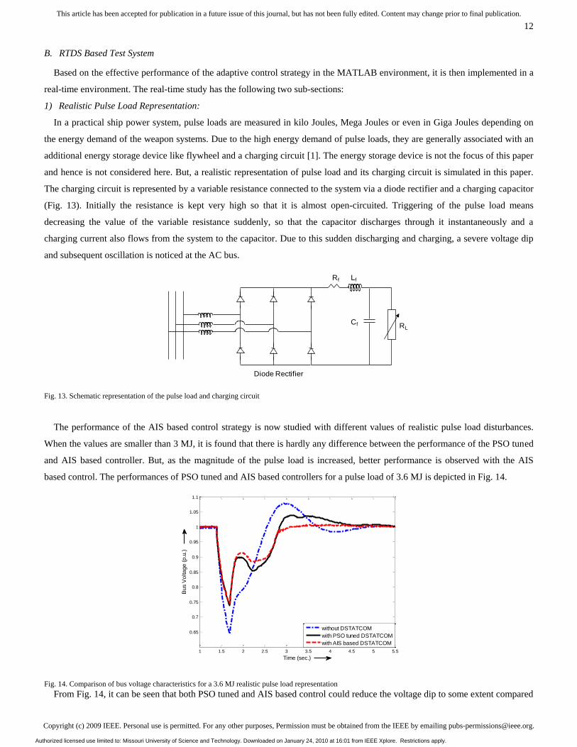
1) Realistic Pulse Load Representation:
In a practical ship power system, pulse loads are measured in kilo Joules, Mega Joules or even in Giga Joules depending on
the energy demand of the weapon systems. Due to the high energy demand of pulse loads, they are generally associated with an
additional energy storage device like flywheel and a charging circuit [1]. The energy storage device is not the focus of this paper
and hence is not considered here. But, a realistic representation of pulse load and its charging circuit is simulated in this paper.
The charging circuit is represented by a variable resistance connected to the system via a diode rectifier and a charging capacitor
(Fig. 13). Initially the resistance is kept very high so that it is almost open-circuited. Triggering of the pulse load means
decreasing the value of the variable resistance suddenly, so that the capacitor discharges through it instantaneously and a
charging current also flows from the system to the capacitor. Due to this sudden discharging and charging, a severe voltage dip
and subsequent oscillation is noticed at the AC bus.
Fig. 13. Schematic representation of the pulse load and charging circuit
The performance of the AIS based control strategy is now studied with different values of realistic pulse load disturbances.
When the values are smaller than 3 MJ, it is found that there is hardly any difference between the performance of the PSO tuned
and AIS based controller. But, as the magnitude of the pulse load is increased, better performance is observed with the AIS
based control. The performances of PSO tuned and AIS based controllers for a pulse load of 3.6 MJ is depicted in Fig. 14.
Fig. 14. Comparison of bus voltage characteristics for a 3.6 MJ realistic pulse load representation
From Fig. 14, it can be seen that both PSO tuned and AIS based control could reduce the voltage dip to some extent compared
LfRf
Diode Rectifier
Cf RL
1 1.5 2 2.5 3 3.5 4 4.5 5 5.5
0.65
0.7
0.75
0.8
0.85
0.9
0.95
1
1.05
1.1
Time (sec.)
Bu
s V
olta
ge
(p
.u.)
without DSTATCOM
with PSO tuned DSTATCOM
with AIS based DSTATCOM
Authorized licensed use limited to: Missouri University of Science and Technology. Downloaded on January 24, 2010 at 16:01 from IEEE Xplore. Restrictions apply.
Copyright (c) 2009 IEEE. Personal use is permitted. For any other purposes, Permission must be obtained from the IEEE by emailing [email protected].
This article has been accepted for publication in a future issue of this journal, but has not been fully edited. Content may change prior to final publication.
13
to the system without DSTATCOM. It is also observed that the post disturbance overshoot is negligible with the AIS based
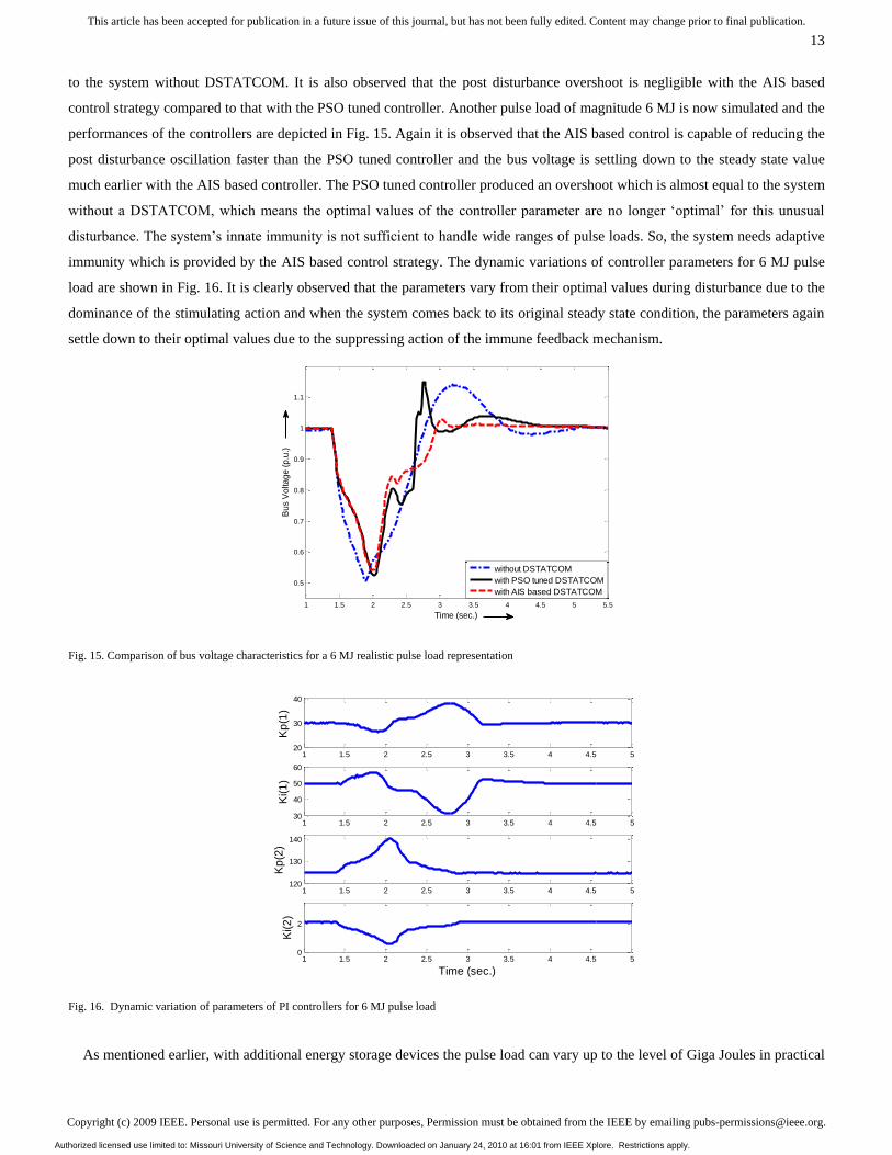
control strategy compared to that with the PSO tuned controller. Another pulse load of magnitude 6 MJ is now simulated and the
performances of the controllers are depicted in Fig. 15. Again it is observed that the AIS based control is capable of reducing the
post disturbance oscillation faster than the PSO tuned controller and the bus voltage is settling down to the steady state value
much earlier with the AIS based controller. The PSO tuned controller produced an overshoot which is almost equal to the system
without a DSTATCOM, which means the optimal values of the controller parameter are no longer ‗optimal‘ for this unusual
disturbance. The system‘s innate immunity is not sufficient to handle wide ranges of pulse loads. So, the system needs adaptive
immunity which is provided by the AIS based control strategy. The dynamic variations of controller parameters for 6 MJ pulse
load are shown in Fig. 16. It is clearly observed that the parameters vary from their optimal values during disturbance due to the
dominance of the stimulating action and when the system comes back to its original steady state condition, the parameters again
settle down to their optimal values due to the suppressing action of the immune feedback mechanism.
Fig. 15. Comparison of bus voltage characteristics for a 6 MJ realistic pulse load representation
Fig. 16. Dynamic variation of parameters of PI controllers for 6 MJ pulse load
As mentioned earlier, with additional energy storage devices the pulse load can vary up to the level of Giga Joules in practical
1 1.5 2 2.5 3 3.5 4 4.5 5 5.5
0.5
0.6
0.7
0.8
0.9
1
1.1
Time (sec.)
Bu
s V
olta
ge
(p
.u.)
without DSTATCOM
with PSO tuned DSTATCOM
with AIS based DSTATCOM
1 1.5 2 2.5 3 3.5 4 4.5 520
30
40
Kp
(1)
1 1.5 2 2.5 3 3.5 4 4.5 530
40
50
60
Ki(1
)
1 1.5 2 2.5 3 3.5 4 4.5 5120
130
140
Kp
(2)
1 1.5 2 2.5 3 3.5 4 4.5 50
2
Time (sec.)
Ki(2
)
Authorized licensed use limited to: Missouri University of Science and Technology. Downloaded on January 24, 2010 at 16:01 from IEEE Xplore. Restrictions apply.
Copyright (c) 2009 IEEE. Personal use is permitted. For any other purposes, Permission must be obtained from the IEEE by emailing [email protected].
This article has been accepted for publication in a future issue of this journal, but has not been fully edited. Content may change prior to final publication.
14
battle conditions. But, since no energy storage device is used in this study and the DSTATCOM has limitations in supplying
active power, it is observed for this test system that the voltage dip cannot be improved further with the application of
DSTATCOM if a realistic pulse load of 6 MJ or above is applied. But, the DSTATCOM can damp out the post pulse load
oscillations quickly by controlling the reactive power injection. The role of DSTATCOM in controlling the voltage dip as well
as the post disturbance oscillation can also be prominently observed if the load contains certain amount of reactive power.
Hence, some futuristic scenarios of pulse loads containing a large amount of reactive power are also studied to observe the
performance of the AIS based control strategy in worst hypothetical cases.
2) Futuristic Worst Case Scenarios:
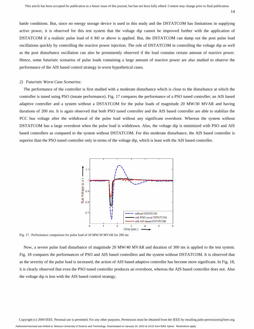
The performance of the controller is first studied with a moderate disturbance which is close to the disturbance at which the
controller is tuned using PSO (innate performance). Fig. 17 compares the performance of a PSO tuned controller; an AIS based
adaptive controller and a system without a DSTATCOM for the pulse loads of magnitude 20 MW/30 MVAR and having
durations of 200 ms. It is again observed that both PSO tuned controller and the AIS based controller are able to stabilize the
PCC bus voltage after the withdrawal of the pulse load without any significant overshoot. Whereas the system without
DSTATCOM has a large overshoot when the pulse load is withdrawn. Also, the voltage dip is minimized with PSO and AIS
based controllers as compared to the system without DSTATCOM. For this moderate disturbance, the AIS based controller is
superior than the PSO tuned controller only in terms of the voltage dip, which is least with the AIS based controller.
Fig. 17. Performance comparison for pulse load of 20 MW/30 MVAR for 200 ms
Now, a severe pulse load disturbance of magnitude 20 MW/40 MVAR and duration of 300 ms is applied to the test system.
Fig. 18 compares the performances of PSO and AIS based controllers and the system without DSTATCOM. It is observed that
as the severity of the pulse load is increased, the action of AIS based adaptive controller has become more significant. In Fig. 18,
it is clearly observed that even the PSO tuned controller produces an overshoot, whereas the AIS based controller does not. Also
the voltage dip is less with the AIS based control strategy.
Authorized licensed use limited to: Missouri University of Science and Technology. Downloaded on January 24, 2010 at 16:01 from IEEE Xplore. Restrictions apply.
Copyright (c) 2009 IEEE. Personal use is permitted. For any other purposes, Permission must be obtained from the IEEE by emailing [email protected].
This article has been accepted for publication in a future issue of this journal, but has not been fully edited. Content may change prior to final publication.
15
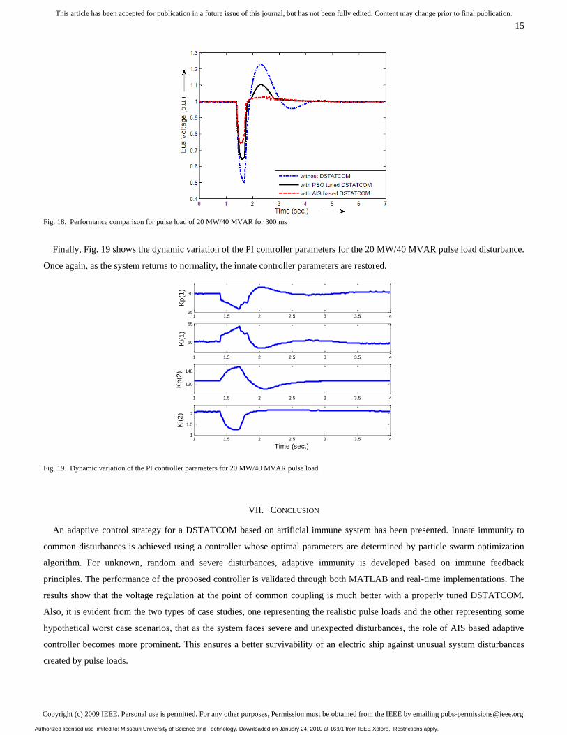
Fig. 18. Performance comparison for pulse load of 20 MW/40 MVAR for 300 ms
Finally, Fig. 19 shows the dynamic variation of the PI controller parameters for the 20 MW/40 MVAR pulse load disturbance.
Once again, as the system returns to normality, the innate controller parameters are restored.
Fig. 19. Dynamic variation of the PI controller parameters for 20 MW/40 MVAR pulse load
VII. CONCLUSION
An adaptive control strategy for a DSTATCOM based on artificial immune system has been presented. Innate immunity to
common disturbances is achieved using a controller whose optimal parameters are determined by particle swarm optimization
algorithm. For unknown, random and severe disturbances, adaptive immunity is developed based on immune feedback
principles. The performance of the proposed controller is validated through both MATLAB and real-time implementations. The
results show that the voltage regulation at the point of common coupling is much better with a properly tuned DSTATCOM.
Also, it is evident from the two types of case studies, one representing the realistic pulse loads and the other representing some
hypothetical worst case scenarios, that as the system faces severe and unexpected disturbances, the role of AIS based adaptive
controller becomes more prominent. This ensures a better survivability of an electric ship against unusual system disturbances
created by pulse loads.
1 1.5 2 2.5 3 3.5 425
30
Kp
(1)
1 1.5 2 2.5 3 3.5 4
50
55
Ki(1
)
1 1.5 2 2.5 3 3.5 4
120
140
Kp
(2)
1 1.5 2 2.5 3 3.5 41
1.5
2
Time (sec.)
Ki(2
)
Authorized licensed use limited to: Missouri University of Science and Technology. Downloaded on January 24, 2010 at 16:01 from IEEE Xplore. Restrictions apply.
Copyright (c) 2009 IEEE. Personal use is permitted. For any other purposes, Permission must be obtained from the IEEE by emailing [email protected].
This article has been accepted for publication in a future issue of this journal, but has not been fully edited. Content may change prior to final publication.
16
The beauty of the proposed adaptive controller is that the original optimal controller parameters are restored as the system
returns to normality. This is unique for a controller that is adaptive. Such as an adaptive controller has potential for effective
control of power electronics devices operating in nonlinear environments.
Future study on implementing the AIS control strategy on a physical DSTATCOM hardware and validating the effectiveness
of the controller on an electric ship power system remains to be investigated. The adaptive AIS control strategy presented in this
paper has potential for applications in the smart power grid environment where there are possibilities of unforeseen energy and
load fluctuations.
APPENDIX
Fig. A-1. RSCAD model of the test system
Authorized licensed use limited to: Missouri University of Science and Technology. Downloaded on January 24, 2010 at 16:01 from IEEE Xplore. Restrictions apply.
Copyright (c) 2009 IEEE. Personal use is permitted. For any other purposes, Permission must be obtained from the IEEE by emailing [email protected].
This article has been accepted for publication in a future issue of this journal, but has not been fully edited. Content may change prior to final publication.
17
Fig. A-2. Small time-step model of the propulsion motor with VSC
VSC Based Drives
Interfacing
Transformers
Propulsion
Motor
VSC Based Drives
Interfacing
Transformers
Propulsion
Motor
Authorized licensed use limited to: Missouri University of Science and Technology. Downloaded on January 24, 2010 at 16:01 from IEEE Xplore. Restrictions apply.
Copyright (c) 2009 IEEE. Personal use is permitted. For any other purposes, Permission must be obtained from the IEEE by emailing [email protected].
This article has been accepted for publication in a future issue of this journal, but has not been fully edited. Content may change prior to final publication.
18
REFERENCES
[1] M. Steurer, M. Andrus, J. Langston, L. Qi, S. Suryanarayanan, S. Woodruff and P.F. Ribeiro, ―Investigating the Impact of Pulsed Power Charging Demands
on Shipboard Power Quality‖, Proceedings of the IEEE Electric Ship Technologies Symposium, 2007, ESTS ‘07, pp. 315-321.
[2] T. A. Baginski, K. A, Thomas, ―A Robust One-Shot Switch for High-Power Pulse Applications‖, IEEE Trans. Power Electronics, Vol. 24, No. 1, Jan.
2009, pp. 253–259.
[3] A. Shukla, A. Ghosh and A. Joshi ―Control Schemes for DC Capacitor Voltages Equalization in Diode-Clamped Multilevel Inverter-Based DSTATCOM‖,
IEEE Transactions on Power Delivery, Vol. 23, No 2, April 2008.pp1139-1149.
[4] A. Ghosh and G. Ledwich, ―Applications of Power Electronics to Power Distribution Systems‖, IEEE Tutorial Course, 2006.
[5] M. K. Mishra, A. Joshi, and A. Ghosh, ―Control Schemes for Equalization of Capacitor Voltages in Neutral Clamped Shunt Compensator‖ IEEE Trans.
Power Del., Vol. 18, No. 2, Apr. 2003, pp. 538–544.
[6] A. Shukla, A. Ghosh, and A. Joshi, ―Hysteresis Current Control Operation of Flying Capacitor Multilevel Inverter and its Application in Shunt
Compensation of Distribution Systems,‖ IEEE Trans. Power Del., vol. 22, no. 1, pp. 396–405, Jan. 2007.
[7] A. Shukla, IEEE, A. Ghosh, and A. Joshi ―State Feedback Control of Multilevel Inverters for DSTATCOM Applications,‖ IEEE Transactions on Power
Delivery, Vol. 22, No. 4, October 2007, pp. 2409-2418.
[8] R. Gupta And A. Ghosh, ―Frequency-Domain Characterization of Sliding Mode Control of an Inverter Used in DSTATCOM Application,‖ IEEE
Transactions on Circuits and Systems—I: Regular Papers, Vol. 53, No. 3, March 2006, pp. 662-676.
[9] M. A. Eldery, E. F. El-Saadany, and M. M. A. Salama, ―Sliding Mode Controller for Pulse Width Modulation Based DSTATCOM‖, Proceedings of
Canadian Conference on Electrical and Computer Engineering, CCECE ‘06, pp. 2216-2219.
[10] Y. Xiao-ping, Z. Yan-ru, W. Yan, ―A Novel Control Method for DSTATCOM Using Artificial Neural Network,‖ CES/IEEE 5th International Power
Electronics and Motion Control Conference, 2006. IPEMC '06. Volume 3, 14-16 Aug. 2006, pp.1– 4.
[11] B. Singh, J. Solanki and V. Verma, ―Neural Network Based Control of Reduced Rating DSTATCOM,‖ Annual IEEE Conference, INDICON, 2005, 11-13
Dec. 2005 pp. 516 – 520.
[12] Mani Hunjan, Ganesh K. Venayagamoorthy, ―Adaptive Power System Stabilizers Using Artificial Immune System‖, Proceedings of the IEEE Symposium
on Artificial Life, CI-ALife 2007, pp. 440-447.
[13] D. Dasgupta and S. Forrest, ―Artificial Immune Systems in Industrial Applications‖, Proceedings of the 2nd International Conference on Intelligent
Processing and Manufacturing of Materials, 1999, vol. 1, pp. 257-267.
[14] P. Mitra, G. K. Venayagamoorthy, ―Artificial Immune System Based DSTATCOM Control for an Electric Ship Power System‖, 39th IEEE Power
Electronics Specialist Conference, PESC 2008, June 15-19, 2008, pp. 718-723.
[15] S. Kannan et.al., "Real and Reactive Power Coordination for a Unified Power Flow Controller", IEEE Transactions on Power Systems, Vol. 19, No. 3, Aug.
2004, pp. 1454-1461.
[16] del Valle, Y., Venayagamoorthy, G. K., Mohagheghi, S., Hernandez, J. and Harley, R. G.: ‗Particle Swarm Optimization: Basic Concepts, Variants and
Applications in Power System‘, IEEE Transactions on Evolutionary Computation, April 2008, 12, no. 2, pp. 171-195.
Authorized licensed use limited to: Missouri University of Science and Technology. Downloaded on January 24, 2010 at 16:01 from IEEE Xplore. Restrictions apply.