an analysis of the zachman framework for enterprise architecture from the geram perspective
TRANSCRIPT

Annual Reviews in Control 27 (2003) 163–183
An analysis of the Zachman framework for enterprisearchitecture from the GERAM perspective
Ovidiu Noran∗
Griffith University, Brisbane, Australia
Received 18 August 2003; received in revised form 30 August 2003; accepted 8 September 2003
Abstract
This article presents an analysis of the Zachman framework for enterprise architecture and its mapping onto the Generalised EnterpriseReference Architecture and Methodology (GERAM) framework/ISO IS15704:2000 requirements. Aspects covered concern the ability of theZachman framework to cover the complete scope of the GERAM metamodel, such as life cycle/life history concepts, modelling framework,enterprise entities and entity recursion, associated enterprise engineering methodologies, modelling languages and reference models.© 2003 Elsevier Ltd. All rights reserved.
Keywords: Reference model; Enterprise modelling; Life cycle phase; Modelling framework; Modelling language
1. Introduction
This analysis aims to assist prospective users of the Zach-man framework in employing the ISO15704:2000/GERAMset of requirements, in order to check how the Zachmanframework meets (or can be used to meet) the needs of anenterprise architecture project or program. The user maythen use mappings of other architecture frameworks ontoGERAM (such as described inNoran, 2003) to completethis framework if needed.
1.1. A short introduction and history of GERAM
The main aim of the Generalised Enterprise ReferenceArchitecture and Methodology (Bernus, 2001; ISO/TC184/SC5/WG1, 2000a) is to generalise the contributions ofvarious existing and emerging Enterprise ArchitectureFrameworks and Enterprise Reference Architectures. Notethat the term ‘reference architecture’ will be used withinthis paper interchangeably with ‘modelling framework’for simplicity; reference architectures (such as GERA) inISO/TC184/SC5/WG1 (2000a)may include other concepts,such as ‘life history’. Historically, the abbreviation GERAMmeans a reference architecture and methodology. However,
∗ Tel.: +61-7-3875-5039; fax:+61-7-3875-5051.E-mail address: [email protected] (O. Noran).
as it becomes evident in the use of GERAM, onlyone com-ponent of the framework, namely, GERA is the life-cyclearchitecture; another one is the Methodology, and there areother important components as well (as shown inFig. 1).
The aim of GERAM is to define a complete collectionof tools, methods and models that can be employed by anenterprise engineering and integration effort. GERAM as-sists in choosing tools and methodologies by providing cri-teria that need to be satisfied, rather than trying to enforceparticular options. Used as a generalisation of frameworks,GERAM may also assist in establishing the completenessand suitability of frameworks proposed to form the basis toa particular change process (since management may choseto combine the elements of more than one framework anduse these in combination).
There have been several notable attempts to map the ex-isting life cycle architectures and their associated artefactsagainst each another (e.g.Williams, Zoetekouw, Shewchuck,Chen, & Li, 1996), which have highlighted some of the dif-ficulties encountered in the mapping process (note that theterms ‘life cycle architecture’ and ‘architecture framework’will be used interchangeably in this paper, and with themeaning of the complete set of artefacts provided by an ar-chitecture framework, as shown inFig. 1). The result of themappings of existing architectures against a fixed referencewas a matrix-like structure of requirements (Bernus, Nemes,& Williams, 1996b)—a two-dimensional form of the GERAmodelling framework.
1367-5788/$ – see front matter © 2003 Elsevier Ltd. All rights reserved.doi:10.1016/j.arcontrol.2003.09.002

164 O. Noran / Annual Reviews in Control 27 (2003) 163–183
EM
GERA
employsIdentifies concepts of
Enterprise Integration
Generalised Enterprise Reference Architecture
EEM
Describes process of enterprise engineering
Enterprise Engineering Methodology
1..* 1..*
utilises
EML
Provides modelling constructs for processes, technologies and human role
Enterprise Modelling Language0..* 1..*
EET
Supports Enterprise Engineering
Enterprise Engineering Tool
implemented in
Supports Enterprise Engineering
Enterprise Model
used to build
EOS
Supports the operation of the particular Enterprise
Enterprise Operational System
used to implement
PEM
Provides reusable reference models and designs of
processes, technologies and human roles
Partial Enterprise Model
supports
0..*
0..*
GEMC
Defines the meaning of enterprise modelling constructs
Generic Enterprise Modelling Concept
EMO
Provides implementable modules of operational processes, technologies and human professions
Enterprise Module0..*
0..*
1..*
used to implement
1..*
1..*supports
1..*
1..*
0..*
0..*
implemented in 0..*
0…*
is a kind of
Fig. 1. A possible GERAM metamodel (based on ISO/TC184/SC5/WG1, 2000a).
The modelling framework was then supplemented withspecific concepts such as entity type, recursion, life history,etc. The architecture framework was subsequently built byputting together the generalised modelling framework withall essential generic concepts of enterprise engineering/modelling-such as enterprise models, modelling languages,generic enterprise modelling concepts, partial models, etc.In addition, a three-dimensional representation of the mod-elling framework, proposed by Williams and Li (at meetingsof the IFIP-IFAC Task Force), has improved the readabilityof the previously used two-dimensional matrix. The cur-rent outcome of these efforts is reflected in the GERAMdocument contained in IFIP-IFAC Task Force (2003) andISO/TC184/SC5/WG1 (2000a).
GERAM, as a generalised architecture framework, aimsto categorize life cycle architectures and their associatedartefact types (methodologies, reference models, ontologies,etc.). As such, GERAM may resemble an empty bookcaseproviding shelves for content in the field of enterprise in-tegration, and it may provide a to-do list for a given en-terprise integration task. GERAM alone cannot be used toengineer an enterprise; however, it should be used to as-sess what is needed for a given enterprise integration task(or task type).
The following analysis will focus on the Zachman frame-work and demonstrates how it may be used to cover theGERAM metamodel shown in Fig. 1, hence discussing:
• use of Zachman reference architecture to cover theGERAM life cycle and life history concepts;
• modelling languages proposed in Zachman’s modellingframework;
• enterprise engineering methodologies;• reference models;• other important elements in the GERAM framework
(generic modelling concepts, enterprise modules, mod-elling tools, etc.) and how they apply to the Zachmanframework.
2. Life cycle phases
Mainstream system engineering and enterprise integrationliterature acknowledges the existence of two main types ofarchitectures: architectures that represent the structure of asystem at a given point in time (snapshot) and life cycle ar-chitectures, which describe the possible phases and artefactsinvolved in the life of a system (such as conception, devel-opment, build, operation, dissolution etc.).

O. Noran / Annual Reviews in Control 27 (2003) 163–183 165
An essential part of the requirements for a life cycle ar-chitecture is to include the concept of life cycle phase, un-derstood as a set of possible processes (a “partially orderedset of enterprise activities” , ISO/TC184/SC5/WG1, 2000b)or activities, which may be-once, several times, or not atall-be performed in the enterprise during its existence (i.e.throughout its life history).
Common misconceptions (mainly originating from a lackof consistent terminology across the field) may lead to theflawed conclusion that life cycle phases imply succession,i.e. a temporal aspect. Several such fallacies were described,and solutions proposed in Noran (2000) (e.g. phase versusstage, life cycle versus life history, etc.). The life cycle di-mension in the GERA sense abstracts from time and it issimply a repository of possible processes performed duringthe life history of a system, categorised according to thelevel of abstraction used by these processes to consider theenterprise entity in question. For example, the identificationand the design processes may consider the enterprise entityin question on different levels of abstraction. Some of theseprocesses may be performed repeatedly, and in different suc-cession; some may not occur at all during the existence ofthe system.
2.1. The Zachman life cycle aspect
The Zachman framework takes a somewhat original ap-proach towards life cycle, presenting life cycle phases asperspectives of the various stakeholders involved in theenterprise engineering effort. Although the concepts of lifecycle and life cycle phases are not explicitly present, a map-ping is still possible. This is because the different levels ofabstraction used by the various stakeholders to consider theenterprise entity in question match the GERAM life-cyclephases. Note that a direct mapping is not possible, since
Life-cycle phases
Design
Prelim. design
Detailed design
Identification
Concept
Implementation
Operation
Decommission
Requirements
Objectives / Scope
Business Owner’s View
Architect’s View
Builder’s View
Scontractor’s View
Functioning System
Fig. 2. Mapping of Zachman perspectives to life cycle phases of GERA (other Zachman and GERA frameworks’ dimensions omitted for clarity).
GERA contains types of activities, while Zachman describesdeliverables that given stakeholders produce.
The Zachman framework does not include a stakeholderperspective that can explicitly and completely match theGERA Identification phase. However, in analysing the con-tents of the Zachman cells in the Objectives/Scope row(refer Fig. 2) one realizes that these cells contain deliver-ables that describe the business (term used interchangeablywith ‘enterprise’ within this paper), such as very high-levelfunctional/organisational structure, boundaries, etc.—whichmatch deliverables created in the GERA Identification phase.However, the Zachman framework cells also describe busi-ness goals and strategy (which are developed in GERA’sConcept phase). Hence, the Objectives Scope perspectivemaps onto the GERA Identification and Concept life cyclephases. Note that, although a direct mapping is not possible,the term ‘mapping’ is used in this section with the meaningof association of deliverables and stakeholders perspectives(Zachman) with types of activities within a life cycle phase(GERA).
As shown above, a single GERA phase may map onto sev-eral Zachman perspectives, and several GERA phases mayconverge to a single Zachman perspective. As an example:the Requirements phase maps to both the Business Owner’sperspective and the Architect’s perspective. This is becausethe architect should be able to gather user requirements andtranslate them into system requirements (which must be sat-isfied by the Preliminary Design). Bridging across user andsystem requirements is optimal if e.g. the architect is in-volved both in the GERA Requirements and PreliminaryDesign phases.
The reader is also cautioned that mappings such as shownin Fig. 2 highly depend on the scope and size of the artefactbeing modelled and consequently on the modelling strat-egy adopted. For example, in the case of a large project
166 O. Noran / Annual Reviews in Control 27 (2003) 163–183
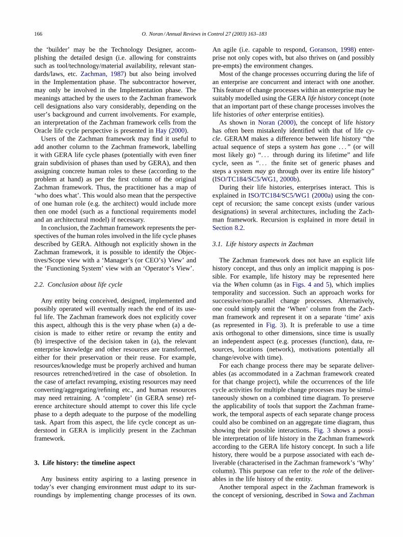
the ‘builder’ may be the Technology Designer, accom-plishing the detailed design (i.e. allowing for constraintssuch as tool/technology/material availability, relevant stan-dards/laws, etc. Zachman, 1987) but also being involvedin the Implementation phase. The subcontractor however,may only be involved in the Implementation phase. Themeanings attached by the users to the Zachman frameworkcell designations also vary considerably, depending on theuser’s background and current involvements. For example,an interpretation of the Zachman framework cells from theOracle life cycle perspective is presented in Hay (2000).
Users of the Zachman framework may find it useful toadd another column to the Zachman framework, labellingit with GERA life cycle phases (potentially with even finergrain subdivision of phases than used by GERA), and thenassigning concrete human roles to these (according to theproblem at hand) as per the first column of the originalZachman framework. Thus, the practitioner has a map of‘who does what’ . This would also mean that the perspectiveof one human role (e.g. the architect) would include morethen one model (such as a functional requirements modeland an architectural model) if necessary.
In conclusion, the Zachman framework represents the per-spectives of the human roles involved in the life cycle phasesdescribed by GERA. Although not explicitly shown in theZachman framework, it is possible to identify the Objec-tives/Scope view with a ‘Manager’s (or CEO’s) View’ andthe ‘Functioning System’ view with an ‘Operator’s View’ .
2.2. Conclusion about life cycle
Any entity being conceived, designed, implemented andpossibly operated will eventually reach the end of its use-ful life. The Zachman framework does not explicitly coverthis aspect, although this is the very phase when (a) a de-cision is made to either retire or revamp the entity and(b) irrespective of the decision taken in (a), the relevantenterprise knowledge and other resources are transformed,either for their preservation or their reuse. For example,resources/knowledge must be properly archived and humanresources retrenched/retired in the case of obsoletion. Inthe case of artefact revamping, existing resources may needconverting/aggregating/refining etc., and human resourcesmay need retraining. A ‘complete’ (in GERA sense) ref-erence architecture should attempt to cover this life cyclephase to a depth adequate to the purpose of the modellingtask. Apart from this aspect, the life cycle concept as un-derstood in GERA is implicitly present in the Zachmanframework.
3. Life history: the timeline aspect
Any business entity aspiring to a lasting presence intoday’s ever changing environment must adapt to its sur-roundings by implementing change processes of its own.
An agile (i.e. capable to respond, Goranson, 1998) enter-prise not only copes with, but also thrives on (and possiblypre-empts) the environment changes.
Most of the change processes occurring during the life ofan enterprise are concurrent and interact with one another.This feature of change processes within an enterprise may besuitably modelled using the GERA life history concept (notethat an important part of these change processes involves thelife histories of other enterprise entities).
As shown in Noran (2000), the concept of life historyhas often been mistakenly identified with that of life cy-cle. GERAM makes a difference between life history “ theactual sequence of steps a system has gone . . . ” (or willmost likely go) “ . . . through during its lifetime” and lifecycle, seen as “ . . . the finite set of generic phases andsteps a system may go through over its entire life history”(ISO/TC184/SC5/WG1, 2000b).
During their life histories, enterprises interact. This isexplained in ISO/TC184/SC5/WG1 (2000a) using the con-cept of recursion; the same concept exists (under variousdesignations) in several architectures, including the Zach-man framework. Recursion is explained in more detail inSection 8.2.
3.1. Life history aspects in Zachman
The Zachman framework does not have an explicit lifehistory concept, and thus only an implicit mapping is pos-sible. For example, life history may be represented herevia the When column (as in Figs. 4 and 5), which impliestemporality and succession. Such an approach works forsuccessive/non-parallel change processes. Alternatively,one could simply omit the ‘When’ column from the Zach-man framework and represent it on a separate ‘ time’ axis(as represented in Fig. 3). It is preferable to use a timeaxis orthogonal to other dimensions, since time is usuallyan independent aspect (e.g. processes (function), data, re-sources, locations (network), motivations potentially allchange/evolve with time).
For each change process there may be separate deliver-ables (as accommodated in a Zachman framework createdfor that change project), while the occurrences of the lifecycle activities for multiple change processes may be simul-taneously shown on a combined time diagram. To preservethe applicability of tools that support the Zachman frame-work, the temporal aspects of each separate change processcould also be combined on an aggregate time diagram, thusshowing their possible interactions. Fig. 3 shows a possi-ble interpretation of life history in the Zachman frameworkaccording to the GERA life history concept. In such a lifehistory, there would be a purpose associated with each de-liverable (characterised in the Zachman framework’s ‘Why’column). This purpose can refer to the role of the deliver-ables in the life history of the entity.
Another temporal aspect in the Zachman framework isthe concept of versioning, described in Sowa and Zachman

O. Noran / Annual Reviews in Control 27 (2003) 163–183 167
Fig. 3. Possible life history interpretation in Zachman.
(1992) as one of the three aspects of recursion applicableto the Zachman framework (refer Section 8.2.1 for details).Versioning may be considered a temporal concept, since itidentifies stages in the evolution (hence, in the life history)of an artefact (note that in this sense, versioning is presentin an implicit form in all reviewed frameworks).
3.2. Conclusion about life history
The concept of life history is important in modelling mul-tiple and overlapping change processes. Acknowledgementof the concept of life history implies its separation from thelife cycle concept and its consideration as an independentdimension. Life history is composed of life cycle phase ac-tivities that occur in time. At any stage (i.e. time interval)during the life history, one or more life cycle phases’ activ-ities of one or more change processes may occur.
Although the Zachman framework does not provide adedicated concept, it still acknowledges a succession ofsteps during the life of the modelled entity. Based on theentity’s history (past succession of life cycle activities),one may (and should) make appropriate selections fromthe pool of life cycle phases and thus influence the futurelife history of the entity. For this purpose, possible futurelife histories may be represented on alternative life historydiagrams.
4. Modelling framework
The GERA Reference Architecture includes the definitionof the GERA Modelling Framework. The significance of themodelling framework is in the fact that it defines the scopeof potential models that change processes may need to use,or to produce. Therefore, the explicit (and implicit) scopeof the Zachman framework will be investigated here. Thereare two main questions to be asked:
• what explicit guidance is provided by the Zachman frame-work about the potential list of models that might need tobe created during the course of various change processes(e.g. a higher granularity modelling framework gives morespecific advice on the kinds of models compared to a lowgranularity modelling framework);
• to what extent is the Zachman framework able to accom-modate the complete scope of modelling as defined in theGERA Modelling Framework? This represents the im-plicit ability of the framework to accommodate any modelthat might be required, even though the framework givesno specific help for the user to identify that model as apotential candidate deliverable.
The reader should note that irrespective of the specific wayin which a given architecture’s modelling framework de-cides to subdivide views, these subdivisions should be views

168 O. Noran / Annual Reviews in Control 27 (2003) 163–183
of an integrated metamodel. Thus, the way views are subdi-vided is less important, as long as the combined scope of themodelling framework is complete. For example, it should bepossible (using e.g. an enterprise engineering tool) to look atthe collection of integrated enterprise models through any ofthe views defined in the various existing modelling frame-works. This is presently not possible because of the lack ofa commonly agreed metamodel and ontology for integratedenterprise models.
4.1. Zachman’s modelling framework
Information (sub)systems have always been part of busi-nesses (enabled by the information technologies historicallyavailable), but they have dramatically increased in impor-tance within the last decade. The Zachman framework ini-tially addressed the information subsystem of an enterprise(Zachman, 1987) and also appeared to be restricted to themodelling framework component of the architecture frame-work. Subsequently, the scope of the framework has beenextended to cover aspects informally defined in the pre-vious version (Sowa & Zachman, 1992). This extensionand formalisation, together with the emergence of mod-elling methodologies and partial models have provided forthe evolution of the original Zachman modelling frame-work into the Zachman architecture framework. The initialname of the Zachman framework. ‘Framework for Infor-mation Systems Architecture’ (Zachman, 1987) was subse-quently changed to ‘Framework for Enterprise Architecture’(Zachman, 2000a), possibly in order to reflect and supportthis evolution.
A mapping of the Zachman framework ‘abstractions’ ontothe GERA Function/Information/Resource/Organisation
Fig. 4. Modelling framework mapping using the GERA F, I, R, O views.
views is shown in Fig. 4. The Zachman framework clearlyacknowledges the Information aspect via the Data ab-straction, onto which the GERA Information view may bemapped (a direct mapping is again not possible also becausegenerally, information is data interpreted by the user).
The remaining GERA views however, cannot be mappedone-on-one onto the Zachman framework:
• the People abstraction in Zachman may be mapped tothe GERA Organisation view, since it comprises a similarscope. However, people are also a (human) resource-hencethe People abstraction maps onto the Resource view inGERA as well. Note that the GERA modelling frameworkconsiders the Organisation as the relation between humanresources (people) and functions (roles that humans take).Resources (including human resources) are modelled inthe Resource view (i.e. human resources are identified andtheir capabilities are described);
• Zachman’s Function abstraction covers the domain typedefined by the GERA Function view. The Zachman Moti-vation abstraction provides for rule modelling, which alsobelongs to the Functional view in GERA. A reason forthis is that modelling languages used for Function mod-elling usually allow (or require) up-front statements of themodelling context, describing why and for what purposeare the models being constructed;
• The Network abstraction in Zachman covers thenon-human resources-therefore, together with the Peopleabstraction, it maps onto the GERA Resource view.
The mapping of the Motivation abstraction on theGERA Function view deserves an extended explanation.Rule modelling is part of behaviour modelling, which inits turn is part of functional modelling. When modelling

O. Noran / Annual Reviews in Control 27 (2003) 163–183 169
the functional aspects the following degrees of detail maybe observed (not necessarily in the order shown):
• activities are shown with their inputs and outputs (e.g.using IDEF0-ICAM, USAF Integrated Computer AidedManufacturing, DEFinition Function Modelling Lan-guage, ICAM, 1981) which are objects (but no details ofthese objects are shown);
• events are added (e.g. using Petri Nets, Harel State Charts,State Transition Diagrams, etc.) so as to model systembehaviour/dynamics (reaction to events);
• the input/output objects are detailed, e.g. using ColouredPetri Nets (a specialisation of Petri nets where tokens ownattributes called colours, Jensen, 1992), IDEF3 ObjectState Transition Networks (OSTNs, described in Menzel& Mayer, 1998), etc.;
• pre- and post conditions (rules) are added (e.g. using struc-tured English, decision tables/trees, mathematical logic);
• the temporal dimension is added, e.g. via timed Petri Nets(a specialisation of Petri nets including temporal aspects,i.e. a duration is associated to each transition or eachplace), IDEF3 process flow description, etc.
Therefore, in this context the motivation abstraction maybe considered an extract of the GERA functional view.
In mapping the Zachman framework against the otherGERA views, it will be realised that even within the samecolumn, each cell in the Zachman framework covers GERAaspects to a different extent, depending on the perspective(or row) containing them.
Take for example the network abstraction. At the Objec-tives-, Business Owner’s view and Architect’s view levels,
Management and control
Customerservice
HumanMachine
HardwareSoftware
Views
Instantiation
Sw
Hw
Sw
Hw
Sw
Hw
Sw
Hw
CS CS CS CS CS MCMCMC MC MC
MM H MM H MM H MM H MM HLC phases
Design
Prelim. design
Detailed design
Identification
Concept
Implementation
Operation
Decommission
Requirements
Data(What)
Function(How)
Network(Where)
People(Who)
Time(When)
Motivation(Why)
Objectives /Scope
BusinessOwner’s View
Architect’sView
Builder’s View
Scontractor’sView
FunctioningSystem
Fig. 5. Possible additional views in Zachman according to GERA.
the Network abstraction makes no difference between themission accomplishment and mission control aspects of theenterprise. At the Architect’s-, Builder’s-, Subcontractor’sand Functioning System views, the Network abstraction cov-erage is limited to the locations or structure of non-humanresources, including both hardware and software resources.
Another example is the People (Who) abstraction. Thecells in the upper (Objectives and Business Owner) perspec-tives mainly relate to the human aspects and use conceptssuch as organisational units, mission, organisational chart,etc. However, moving down to the Architect’s, Builder’s andSubcontractor’s perspectives, the focus gradually shifts to-wards the human–machine interaction, and subsequently tointerface specifications (away from the human aspect).
The problem with this approach is that the user cannotreadily see (a) all the possible aspects that could be coveredand (b) which of those possible aspects are indeed coveredat each perspective. A partial solution is to explicitly specifythis information for each cell by attaching separate descrip-tions to the cells in question. Another solution is to use theGERA multi-view approach and create subdivisions insideeach cell of the Zachman framework corresponding to eachof the applicable GERA views (such as shown in Fig. 5). Afilled cell subdivision would then indicate that the matchingGERA aspect is covered within that cell. In Fig. 5, M, Hdenote the Machine and Human aspects in GERA; Hw, Sware the GERA Hardware and Software aspects; and CS, MCare the Customer Service and Management/Control viewsof GERA.
Fig. 6 presents an extract (a single cell) from theright-hand side of Fig. 5, covering the Architect’s view of

170 O. Noran / Annual Reviews in Control 27 (2003) 163–183
Network(Where)
Architect’sView
Sw
Hw
CS MC
MM H
Location / Structure of machinetools controllers software
Location / structure ofControl software: MISdatabase, DSS,..
Location / Structure of ShopFloor Workers Instructions
Location / structure ofManagement personnelInstructions
Location / structure ofMIS and Control hardware
Location / Structure ofCNC / Machine tools
Location ofManagement personnel
Location of ShopFloor Workers
Fig. 6. Extract from Fig. 5.
the Network abstraction and using the descriptions providedin Zachman (1987). The represented cell explicitly coversthe Software and Hardware aspects of the Non-Human(Machine) side of the Management and Control of the en-terprise (the software and hardware non-human side of theCustomer Service (manufacturing) may also be consideredas covered, although this is not explicitly stated in the refer-ence used). This extract is presented primarily to illustratethe potential use of the GERA views to further scope theZachman framework cells and to identify potential coveragegaps and overlaps.
Fig. 7. Possible genericity dimensions in the Zachman framework (shaded areas mark the non-applicable views; the instantiation shown only applies tothe particular Zachman framework).
Note that although the Zachman framework considers theNetwork abstraction to cover location and structure, in thisexample, the Hardware description of the Human side ofboth Management/Control and Customer Service in Fig. 6has been limited to Location. This is mainly due to thepresence of the People abstraction, which may be more ap-propriately used to represent the structure of the enterprisepersonnel (aggregation into organisational entities).
The Zachman framework does not explicitly contain agenericity dimension. However, separate frameworks maybe used for the three main areas of genericity (generic-partial-particular) as defined in GERA. In doing so, however,the ‘Functioning System’ perspective should be omittedfrom the generic and partial frameworks (the shaded areasin Fig. 7). The particular Zachman framework would con-tain fully developed models, while the partial frameworkwould contain reference models (which may be models ofprototypes, ‘class models’ or models of the common partsof a set of enterprises, according to the GERA concept ofpartial model). The generic level framework would thencontain metamodels, i.e. modelling constructs and theirrelationships, ontologies and glossaries.
Referring to Fig. 7, there is another (implicit) genericitydimension along the Perspective axis. The views of the peo-ple involved in the life cycle phases of the artefact may be

O. Noran / Annual Reviews in Control 27 (2003) 163–183 171
“of a different nature” (Zachman, 1987) but they do referto the same artefact (since they belong to the same frame-work) on a different level of detail. For example, a highlevel user requirement in the owner’s view may translateinto several system requirements in the architect’s view, be-come implementable by using a combination of technolo-gies/materials/tools described in the builder’s view and bephysically fulfilled by putting together the components builtin the subcontractor’s view.
Each representation may use specific means of expres-sion, but in essence they refer to the same artefact in variousdegrees of detail. The degree of specialisation of the views(models) will gradually increase as one moves closer tothe functioning system view (downwards, in the Zachmanframework). This happens because decisions have to bemade regarding various system parameters (e.g. the kind ofarchitecture to be used, processes/technology/human skillsto be employed, etc.). Instantiation then occurs when ab-stract representations become reality. This only occurs in theBuilder/Subcontractor View of the particular level Zach-man framework (mapped onto the GERA Implementationphase, refer Fig. 2).
The Zachman framework also appears to include a third,implicit genericity dimension derived from its recursiveness,as subsequently shown in Section 5.1.
4.2. Conclusion about the modelling framework
A modelling framework is a structure containing place-holders for artefacts needed in the modelling process. De-pending on the structure of the framework, the type of theseartefacts may be limited to models, or it may extend to otherconstruct types such as partial models, metamodels, glos-saries, etc. For example, the GERA modelling frameworkcontains placeholders for artefacts whose type is describedin the GERAM metamodel (Fig. 1).
Some of the existing modelling frameworks are‘complete’ in the sense that they can accommodate thecomplete GERA scope, but each goes into detail from dif-ferent aspects. Therefore, the user of any of the architecturesshould consider the GERA scope definition as a guidanceor checklist for potential omissions of deliverables that maybe needed but are not covered in the respective architecture.
Note that it is often the case that several of the possiblesubdivisions shown in Fig. 6 apply only to some modellingtasks. GERA therefore includes subdivisions into views onlywhere the models used in the relevant life cycle phase makea difference between the contents of these views. For exam-ple, the GERA Identification phase does not separate Hu-man/Machine or Function/Information/etc. aspects. This isbecause in GERA the Identification phase abstracts fromdecisions that would need the differentiation between theseaspects.
The reader should also note that, ultimately, it is theenterprise engineering methodology that needs to identifythe models that are necessary to support an enterprise ar-
chitecture endeavour; therefore, the mapping provided inthis article is primarily useful for methodology develop-ers and would not necessarily be utilised directly by endusers. The methodology developer should consider, based onthe objectives of the given change process, which artefactsare necessary and useful—taking into account that practis-ing enterprise architecture is likely to have multiple objec-tives, and that artefacts produced should support every oneof these.
5. Modelling languages
The practice of enterprise modelling needs to producea set of models aimed at an intended audience in order tocommunicate the models’ meanings. In order to achieve thispurpose, the models must be constructed using languagesthat (a) are appropriate to the enterprise aspect modelledand (b) can be understood by the target audience. In assess-ing the appropriateness of the languages for the modellingtask in question, a balance must be struck between theexpressive power and the complexity of the language. Amodelling language contains modelling constructs and rulesto combine them (syntax). Thus, to understand a modelone must be familiar with the language used to constructthat model, hence with its modelling constructs and rules.For this purpose, existing languages may be adopted (as-is,or customised) or new languages may be created. Anyextensions to chosen existing languages must be fully ex-plained and justified, as they in effect change the structure(the metamodel and therefore, implicitly the meaning) ofthe language itself. Newly designed modelling languagesshould be based on reliable ontologies (metamodels withsemantic rules), which will ensure the required consistencyand determine the expressive power of the modelling asrequired by the desired enterprise view.
GERAM contains several requirements regarding mod-elling languages definition (constructs and semantics), ex-pressiveness, required domain coverage of the chosen set ofmodelling languages and the requirement that models pro-duced should be able to be integrated across various subjectareas of enterprise modelling. The integration in questionmay be based on a common ontology of the languagesand/or using integrity constraints. The need for common(integrated) ontology and metamodel is particularly truein the case of some sets of languages (e.g. IDEF), whichare not based on-, or define a common ontology, despiteclaiming to belong to the same ‘ family’ .
5.1. Modelling languages for the Zachman framework
In today’s ever faster changing business environment, itis understandable that reference architectures aim to remainas generic as possible. A balance must however be reachedbetween the degree of genericity, and the level of usabilityof an architecture framework. For example, an excessively

172 O. Noran / Annual Reviews in Control 27 (2003) 163–183
Fig. 8. Zachman framework (based on Sowa & Zachman, 1992).
generic architecture may not provide any useful guidance asto what deliverables may be needed and how to obtain them,while an excessively detailed architecture may constrain theuser towards a particular choice of models/tools and eventechnology (which may become obsolete). An architectureframework may avoid prescribing specific instances of arte-facts (such as a particular modelling language or modellingtool) but still make recommendations or at least describe theessential requirements for such artefacts.
In this respect, the Zachman framework does not attemptto define dedicated language constructs, nor does it try toenforce any particular third-party modelling languages. TheZachman framework does however suggest several possiblemodelling languages in its framework cells (refer Fig. 8).This is done by means of graphical representation (i.e. typi-cal entity and relationship symbols for an ER diagram, mapfor locations, typical Input, Control, Output, Mechanism(ICOM) symbols for IDEF0, etc.). Some recommendationsalso exist in Sowa and Zachman (1992).
Modelling tool and/or methodologies developers mustemploy various proprietary or third-party modelling lan-guages in order to populate their tools and/or method-ologies. The lack of guidance in choosing appropriatemodelling languages for the Zachman framework requiresusers/developers to choose a language they feel appropri-ate for a specific modelling task. No mechanism is offered
however, to ensure the consistency or interoperability of themodels created using the chosen languages-unless this taskis accomplished by choosing a truly integrated family oflanguages (based on common metamodels).
Fig. 9 shows one of the many possible selections of lan-guages. This particular selection has been compiled usinglanguages proposed by Popkin Software (Popkin Software,2001) and additional languages such as First Order Logic(FOL), Structured English and Decision Tables. In Fig. 9,RP denotes Rich Pictures—using symbols (which may becomplemented by text) to express various concepts in asemi-formal manner. ER(M) denotes ER models allowingM:N relationships. IDEF1 (rather than IDEF1x, Menzel &Mayer, 1998) is proposed by the author at this level in orderto maintain a high degree of independence from the methodof implementation. GRAI Nets have been included in theHow abstraction since they may further detail the activitiesinside the decision centres.
5.2. Conclusion about modelling languages
Given the diversity of objectives that underlies enterpriseintegration efforts, practitioners of enterprise architectureneed to be able to select modelling languages that allowthe expression of their intent and design as needed for theparticular task. Architectures such as Zachman aim not

O. Noran / Annual Reviews in Control 27 (2003) 163–183 173
What How Where Who When Why
Scope (Contextual)
RP / English RP / English RP / Map RP / English RP / English RP / English
Enterprise Model (Conceptual)
ER(M), IDEF1,
UML Class
IDEF0, IDEF3 UOB, UML Act,
GRAI NetsGraph
Org Chart, GRAI Grid
GANTT / PERT, IDEF3 OSTN, Timed Petri
Struct English
System Model (Logical)
ER, IDEF1x, UML Class
UML Use Case Data Flow Diag.
UML Component
GRAI Grid, UML Use Case
Data Flow, IDEF3 OSTN, Timed / Colored Petri
FOL, Struct English, Z
Technology Model (Physical)
Relational, UML Class
UML Class, Activity,
Structure Chart
UML Deployment
UML Real Use Case, UI Design
UML Sequence, Collab, State, Statecharts
FOL, Struct English, Z
Components (Out of Context)
DB SchemaProgramming
languageURL, IP, TCP/IP
UI Programming language
Struct EnglishRule spec. In Prg Lang
Functioning Enterprise
DD L(SQL )Machine code
(0/1)
Address, Comm
languageUser / Worker English (Schedule) English
Fig. 9. Possible modelling languages to populate Zachman’s modelling framework.
to prescribe a complete set of languages, instead arguingthat the given engineering domain already has adequatemeans to describe any deliverable, and the architectureis there just to create a checklist of deliverables and tomake their relationships explicit. Such architecture frame-works only give examples of selected typical modellinglanguages.
For some areas of modelling, typical modelling languagesmay be recommended without restricting the use of theframework to a specific application domain or change objec-tive. For example, one could propose the Entity-RelationshipData Model (e.g. using IDEF1x) or UML Class diagramfor information modelling, IDEF0 or Data-Flow Dia-grams for function modelling, and IDEF3 (or alternativelyEvent Driven Process Chain, Petri Nets, CIMOSA pro-cess model, or UML Sequence/Collaboration diagrams)for behaviour/process modelling. On a generic level, thislack of restriction in selecting modelling languages mayallow the modelling framework to gain longevity by beingnon-prescriptive.
Nowadays, most enterprises share some common objec-tives likely to persist for a long time. While these objectivesare quite generic in nature, it is possible to identify com-mon needs of change processes regarding types of models ordescriptions, such as to express ideas, capture requirementsand describe designs. Hence, some Architecture Frameworkspropose a concrete set of modelling languages to (fully orpartially) populate their modelling frameworks. The advan-tage of setting a standard set of modelling languages is thatpeople can be trained in their use, tools can be developed,and in general the communication of the models and de-scriptions becomes easier.
Today, no single existing modelling language by itself iscapable of modelling all necessary aspects of an enterprise.Therefore, in order to completely and meaningfully (Bernus,Nemes, & Morris, 1996a) model an enterprise, one has touse several languages. (Vernadat, 2001) has found an over-whelming number of modelling languages used in many
different non-interoperable tools, having an inconsistent vo-cabulary and based on a weak ontology, or no ontology at all.A solution currently in development is the proposed UnifiedEnterprise Modelling Language (UEML), which is to bebased on an integrated metamodel and ontology and com-posed of a set of core and additional constructs. In order tosucceed, however, such a language must have a large accep-tance and appeal to both business users and modelling tooldevelopers. A major benefit of UEML would be a unificationof the terminology used in enterprise modelling languages.As a clarification of terms, please note that UEML is a spe-cialised language dedicated to enterprise modelling, whileUML, as a somewhat general purpose set of modelling lan-guages, may be used to model UEML constructs (Vernadat,2001).
One should not expect that there would ever be a com-plete, closed and final set of modelling languages suitablefor all projects. One can, however, expect that there willexist reasonably complete integrated sets of constructs thatsupport a significant proportion of the modelling needs forall change processes, with the remaining languages beingselected as needed by the project.
6. Methodologies
According to Fig. 1, GERAM specifies the need forEnterprise Engineering Methodologies (EEMs), which “de-scribe the process of enterprise engineering” (ISO/TC184/SC5/WG1, 2000a). GERA sets several requirements formodelling methodologies, such as:
• the need to cover human role (the need to involve usersin the analysis and design phases);
• the necessity to distinguish between user-oriented andtechnology-oriented design;
• the requirement for the methodologies to use project man-agement techniques;

174 O. Noran / Annual Reviews in Control 27 (2003) 163–183
• the need for an economic aspect (e.g. allow cost and per-formance evaluations and comparisons).
Few methodologies cover the full set of requirements inthe GERA sense. Therefore, it is often necessary to adopt aset of methodologies, rather than one single methodology.Potentially overlapping coverage of the selected methodolo-gies may then be used towards the purpose of triangulation.
6.1. Zachman methodologies
The Zachman framework aims to be generic by not pre-scribing a particular implementation or modelling methodol-ogy. However, some high-level guidance is available. Similarto other frameworks, Zachman identifies (Zachman, 2000b)two main stages in enterprise modelling:
• model the existing enterprise so as to improve existingoperational processes;
• change the enterprise using a generalisation of the modelsdeveloped.
In the first stage, the framework is populated with par-ticular models of the existing enterprise. The second phaseemploys a formalisation and generalisation of the particularmodels in a bottom-up approach, in order to effectively ob-tain partial models (refer Section 7 for more information onpartial (or reference) models.).
Various proprietary modelling methodologies relating tothe Zachman modelling framework have emerged. Amongthese are ForeSight, developed by the Zachman framework’sauthors, the Popkin Process (Popkin Software, 2001), theVisible methodology and Ptech’s Causal Architecture. Thesemethodologies are not described in this paper in more detaildue to their proprietary nature (more information may beobtained from the authors’ web sites—at the time of thiswriting www.zifa.com, www.popkin.com, www.visible.comand www.ptech.com.).
The Popkin process offers a methodology to identify con-tent for the Zachman framework cells, to relate the cellsand to choose the appropriate languages/tools to achievethese goals. The Popkin process methodology also provideshigh-level guidance for choosing a suitable, out-of-the-box‘established’ methodology (Business-, Data-, Structured orObject-oriented modelling).
The Ptech Causal Architecture approach uses Causal LoopDiagrams (or CLDs—a Systems Engineering approach usedto describe cause/effect narratives) models to identify rel-evant content for the Zachman framework cells. CLDs areused in combination with value and causal mappings (Vail,2001) to identify key values and high leverage factors for theenterprise. The Causal Architecture methodology then pro-vides a guidance to map these values to the Zachman cellsand assign priorities to them.
A complete review of all significant methodologies thatcan be used in combination with the Zachman framework isbeyond the scope of this paper.
6.2. Conclusion about methodologies
Enterprise Engineering Methodologies often prescribe acertain selection and/or succession of life cycle phases (i.e.suggest a typical life history) for a given (or a given type of)change process and, as part of this, a modelling methodologythat selects the types of languages and tools in support ofthe selected life-cycle activities.
The modelling methodologies described in Section 6.1mostly concentrate on the technical tasks of model and/ordeliverable development (with little or no emphasis on e.g.the organisational aspect), which may have the effect ofcreating market dependency on particular methodologies. Inaddition, proprietary methodologies are usually difficult toassess due to the lack of publicly available details—whichin the long term may also affect their general acceptance.
Companies need to develop in-house capability to exerciseenterprise architecture, at least to the extent that they arecapable of making informed decisions about the time whenexternal help is needed in the process and about the type ofhelp required.
7. Reference models
Presently, knowledge management and its preservationappear to be the main drivers of enterprise modelling. A‘good’ enterprise model is able to encapsulate (and thereforeconserve) knowledge that may otherwise be lost. Knowl-edge preservation makes most sense in view of its (com-plete or partial) reuse. In enterprise modelling, reuse maybe achieved by means of Reference Models (also referred toas or Partial Models in this paper), displaying various levelsof specialisation (and hence various degrees of applicability,since the more specialised a partial model is, the narrowerthe area of its potential application becomes), describing so-lutions for a particular type of modelling problem. Refer-ence Models are potential resource savers for the enterprisemodeller.
Partial models in the GERA sense may be prototypes, ab-stract models or models of classes of enterprises which mustbe specialised and ultimately instantiated in order to obtainthe model of a particular enterprise. GERA specifies humanrole (organisation, responsibilities, etc.), process and tech-nology as possible domains for the partial models. Emphasisis being laid on partial models covering technology-orientedIT systems and Integrating Services, which greatly assist inthe enterprise engineering effort (this type of partial modelsare similar for most enterprises and thus highly reusable).
The reader should also be aware at this point that architec-tures describe structure at a given level of abstraction—e.g.partial models may exist on the policy level (Concept lifecycle phase), requirements level, architecture level, etc.—even including the detailed design level (where partialmodels might describe various views of an often used actualproduct).
O. Noran / Annual Reviews in Control 27 (2003) 163–183 175
Therefore, in a broader context architectures themselvesmay also be considered partial models. This is in line withthe finding of this paper that the components of architec-ture frameworks may play multiple roles, resulting in thedistinction between such components often being blurred.
7.1. A sample Zachman framework partial model
Zachman does not explicitly (in the GERA sense—i.e.an explicit component in the architecture framework) de-fine the notion of reference models. However, as it has beenshown in Fig. 7, it is possible to define Zachman frameworksat the partial level. A partial level framework may subse-quently be either further specialised (in effect producing an-other, more specific reference model) or instantiated into aparticular framework, applicable to the particular modelledentity.
On the other hand, various applications of the Zachmanframework to specific industry types have been producedby third parties. Note that, similar to the case of modellingmethodologies, most third-party (and Zachman proprietary)partial solutions are not publicly available and therefore notincluded in this review (he reader is directed towards the websites of such developers, previously listed in Section 6.1).Such particular applications of the framework may be con-sidered partial models at various levels of specialisation (al-though they are not specifically included in the Zachmanarchitecture framework).
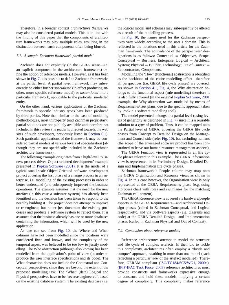
The following example originates from a high-level ‘busi-ness process-driven Object-oriented development’ examplepresented in Popkin Software (2001). It is the model of atypical small-scale Object-Oriented software developmentproject covering the first phase of a change process in an en-terprise, i.e. modelling of the existing processes in order tobetter understand (and subsequently improve) the businessoperations. The example assumes that the need for the newartefact (in this case a software system) has already beenidentified and the decision has been taken to respond to theneed by building it. The project does not attempt to improveor re-engineer, but rather just document the existing pro-cesses and produce a software system to reflect them. It isassumed that the business already has one or more databasescontaining the information, which will be used by the newapplication.
As one can see from Fig. 10, the Where and Whencolumns have not been modelled since the locations wereconsidered fixed and known, and the complexity of thetemporal aspect was believed to be too low to justify mod-elling. The Who abstraction (although also known) has beenmodelled from the application’s point of view (in order toproduce the user interface specifications and its code). TheWhat abstraction does not include the Contextual and Con-ceptual perspectives, since they are beyond the extent of theproposed modelling task. The ‘What’ (data) Logical andPhysical perspectives have to be ‘ reverse engineered’ , basedon the existing database system. The existing database (i.e.
the logical model and schema) may subsequently be alteredas a result of the modelling process.
In Fig. 10, the names used for the Zachman perspec-tives vary widely according to the user’s domain. This isreflected in the notations used in this article for the Zach-man framework. The equivalence of the perspectives’ des-ignations is as follows: Contextual = Objectives, Scope;Conceptual = Business, Enterprise; Logical = Architect,System; Physical = Builder, Technology; Out of Context =Subcontractor, Components.
Modelling the ‘How’ (functional) abstraction is identifiedas the backbone of the entire modelling effort—thereforeall perspectives (i.e. GERA life cycle phases) are covered.As shown in Section 4.1, Fig. 4, the Why abstraction be-longs to the functional aspect (rule modelling) therefore itis also fully covered (in the original Popkin Software, 2001example, the Why abstraction was modelled by means ofRequirements/Test plans, due to the specific approach takenby Popkin’s software modelling tool).
The model presented belongs to a partial level (using lev-els of genericity as described in Fig. 7) since it is a reusablesolution to a type of problem. Thus, it can be mapped ontothe Partial level of GERA, covering the GERA life cyclephases from Concept to Detailed Design on the Manage-ment and Control side (refer Fig. 10), but excluding humans(the scope of the envisaged software product has been con-strained to leave out human resource management aspects).
The GERA Function view is represented in all life cy-cle phases relevant to this example. The GERA Informationview is represented in its Preliminary Design, Detailed De-sign and Implementation life cycle phases.
Zachman framework’s People column may map ontothe GERA Organisation and Resource views as shown inFig. 4. In this case however, the Organisation view is onlyrepresented at the GERA Requirements phase (e.g. usinga process chart with roles and swimlanes for the matchingZachman cell content).
The GERA Resource view is covered via hardware/peopleaspects in the GERA Requirements—and Architectural De-sign phases (called in Zachman Conceptual, and Logicalrespectively), and via Software aspects (e.g. diagrams andcode) at the GERA Detailed Design—and Implementationphases (called in Zachman Physical and Out of Context).
7.2. Conclusion about reference models
Reference architectures attempt to model the structureand life cycle of complex artefacts. In their bid to tacklethis complexity, architectures often employ a ‘divide andconquer’ approach, resulting in more than one model (eachreflecting a particular view of the artefact modelled). There-fore, GERAM-compliant (ISO/TC184/SC5/WG1, 2000a),(IFIP-IFAC Task Force, 2003) reference architectures mustprovide constructs and frameworks expressive enoughto construct and hold these models, implying a certaindegree of complexity. This complexity makes reference

176 O. Noran / Annual Reviews in Control 27 (2003) 163–183
Data (What)
Function(How)
Network(Where)
People (Who)
Time(When)
Motivation(Why)
Contextual(Planner)
Major business processes
Business Requirements& Objectives
Conceptual(Owner)
ProcessChart
Process Chart(w. swimlanes)
Structured English
Logical(Designer)
Class DiagramLogical Data Model
Use CaseDiagram
Use CaseDiagram
FOL, Struct
Physical(Builder)
Class DiagramPhysical Data Model
Class Diagram
Graphic ScreenMenu Diagram
Sequence &Collaboration
Diagram
FOL, Struct English, Z
Out of context(Programmer)
Database Schema
Object-Oriented
Code
Screen and menu code
Rule specificationin OO Code
Func Enterprise(User)
Per
spec
tive
Focus
Implementation
F
Partial Models
R
Hw
Sw
Hw
Sw
Concept
Requirements
PreliminaryDesign
DetailedDesign
HM M
Sw
I
O
CS HwMC
Sw
Hw
English, Z
Fig. 10. Zachman partial model example (based on Popkin Software, 2001) and its mapping onto GERA’s partial model level (cell content shown initalics is optional).
architectures less attractive to business users, since theyalso face the challenge of learning several architectures (noexisting architecture framework presently covers all aspectsspecified by GERA). Each of these architectures potentiallyincludes a framework, modelling methodologies, propri-etary languages, etc. which further increases the necessarylearning effort on the part of the users.
Partial models play an important role in alleviating thesedifficulties, since they are essentially templates that may po-tentially accelerate the learning process (learn by example)and save resources by means of reuse. Therefore, also ac-cording to GERA, the more partial models a reference ar-chitecture encompasses, the easier to learn and use by theusers it becomes. Intuitively, building a partial model is a
two way process: partial models are produced by special-ising generic models and/or generalising existing particularones, while at the same time they need to be validated viaseveral particular models (obtained by instantiating the par-tial model). The validation process is almost certain to mod-ify and enrich the partial model.
Note: within the context of this paper, specialisation isseen as restricting the range of (or making constant) one ormore variables in a generic or partial model (refer Noran,2000) for a concrete example of partial model specialisationapplied to systems’ life cycle standards. In addition, instan-tiation is understood in this context as making constant allthe variables (a significant exception could constitute mod-els containing run-time variables, i.e. meant to be set and

O. Noran / Annual Reviews in Control 27 (2003) 163–183 177
re-set during operation. Such models would in essence beexecutable partial models, producing a new particular modelat run-time with each new reconfiguration).
8. Other relevant constructs
This section aims to cover the rest of the GERAM com-ponents and other relevant components of the GERA, suchas enterprise entity types and their recursivity. Very of-ten, the concepts described in this section are only presentin an implicit form. If the concepts cannot be identified,an attempt is made to determine whether the respectiveframework is compatible with the concept in question—andtherefore could potentially accommodate it.
8.1. Enterprise entity types
The identification of the target Enterprise Entity Types isan essential activity in enterprise architecture. The conceptof entity type provides the means for entity classificationand hence allows a more structured approach towards en-terprise integration. Bernus and Nemes (1994) and Bernusand Nemes (1996) initially defined four types of enter-prises entities: Strategic management. Engineering, Man-ufacturing, and Product. GERA has added a fifth type ofentity, the Methodology. For details on entity types referISO/TC184/SC5/WG1 (2000a).
8.1.1. Entity types in ZachmanZachman does not provide a specialised enterprise entity
type concept. That said, (Sowa & Zachman, 1992) do iden-tify separate frameworks describing various kinds of enti-ties, such as product, manufacturer (which is merely called‘enterprise’ in Sowa & Zachman, 1992), information systemor CASE tool manufacturer (refer Fig. 11). This denotes thatthe Zachman architecture framework does recognize entitytypes in the GERA sense. In addition, in Zachman (simi-lar to GERA), not all entity types are necessarily physical.For example, Zachman defines a ‘knowledge management’framework, while GERA describes a ‘methodology’ entity,both of which are not actual enterprise entities.
8.2. Recursivity of entity types
Recursivity of entity types, as defined in Bernus andNemes (1994) and ISO/TC184/SC5/WG1 (2000a), acknowl-edges the existence of relations of a recursive nature betweenlife cycles of various enterprise entity types. A recursivityexample is as follows: an enterprise of a particular type Xmay support another enterprise of the same type X-thereforethe ‘support for enterprise type X’ function may be definedin terms of itself (typically, an additional invariant is addedto limit the recursion depth).
It is however emphasized that, according to GERA, onlythe Operation life cycle phase of an entity may influence
Fig. 11. Framework recursivity in Zachman (based on Sowa & Zachman,1992 and Inmon, Zachman, & Geiger, 1997).
other entities’ life cycle phases. This section aims to ac-knowledge attempts of the Zachman framework to definerelationships of a recursive nature between (types of) en-terprises (and implicitly between the modelling frameworksrelating to the enterprises in question).
Note that in the following, recursivity is understood asrepetition (e.g. versus decomposition) and refers by defaultto an active and direct influence of one entity in the develop-ment of another entity. An alternative to this direct influenceis the use of one or more deliverables obtained during thecreation of an entity into the development of another, by athird, operating entity.
8.2.1. The recursion concept in the Zachman frameworkZachman identifies three dimensions to the recursivity:
• relation between frameworks associated to entity types;• applying the logic of the Zachman framework to the
framework itself (applicable, but in the author’s opiniononly relevant for a few recursion steps due to exponen-tially increasing complexity);
• versioning of the Zachman frameworks. Because of re-flecting the AS-IS, TO-BE and possible intermediatestates, versioning is also a life history concept. Version-ing based on recursion may imply that a framework ata given point in time is expressed in terms of all of theprevious versions of that particular framework. This maynot always be true (typically, a current version of a par-ticular product is obtained from the most recent versiononly (i.e. only the first recursion step)).
Out of these three aspects of recursivity, only the first typeapplies to entity types via their modelling frameworks, andhence matches the scope of this section. The second and

178 O. Noran / Annual Reviews in Control 27 (2003) 163–183
third recursivity aspects are common to most architectureframeworks, even if not always explicitly stated. For exam-ple, the second type of recursion applies to any architectureframework (including GERAM), because if an architecturedeliverable needs to be developed the life-cycle of this de-liverable should (and can) be described by the frameworkitself—often considered as a ‘sub-project’ , such as custom-ary in systems engineering.
It has been previously shown that the GERA concept ofenterprise type recursion assumes that it is always the Op-erational phase of an entity life cycle that may influence an-other entity (ISO/TC184/SC5/WG1, 2000a). The recursiverelation in GERA explicitly refers to ‘defining, creating, de-veloping and building’ the influenced entity.
The Zachman approach to entity type recursivity appearsto be somewhat different. The relation between entities isrestricted primarily to a descriptive type. Fig. 11 repre-sents this relation between frameworks, identifying prod-ucts, enterprises (manufacturing entities in GERA terms),information systems and CASE tool manufacturers. Thedescriptive character of the relation is revealed in Sowa andZachman (1992), which argues that Row 2 of the manufac-turing entity’s framework (containing the owner/businessview of that entity) contains in fact the complete descriptionof the manufacturing entity’s product(s). For example, thefirst cell from the left (Owner’s View intersected with theWho column) contains all data descriptions relating tothe product(s), second cell (Owner’s View intersected withthe How column) contains all the business processes nec-essary to manufacture the product(s), and so on. Hence, themanufacturing entity framework’s row number two appearsto be rather a metamodel of the product framework.
While the concept shown in Fig. 11 is theoretically valid,it may not be able to cover some situations such as e.g.dynamic self-reconfiguration of a manufacturing entity atrun-time (Row 6). For example a robot (or entire manufac-turing cell) may change its configuration (physical or con-trol) during operation.
In the GERA sense, Row 2 represents the gathering ofuser requirements for the manufacturing entity. The manu-facturing entity is not yet operating and thus it cannot actu-ally perform any action. In the case of re-engineering, theenterprise is operating in parallel with the gathering of newrequirements, however any future products are just beingdescribed as part of the requirements gathered.
If other actions, such as develop, build etc. are to be con-sidered within the recursive relation, then it is not necessarilythe case that a framework should cover the whole of another,but rather only the relevant parts. For example, the manu-facturing entity may have its Context and Business Owner’sviews defined by a management entity and its Architect’sand Builder views defined by an engineering implementa-tion entity, refer ISO/TC184/SC5/WG1 (2000a) and Noran(2004) for a typical examples.
It is therefore suggested that a recursive relation involvingdefinition, development, building, etc. should originate from
Row 6 of the ‘parent’ (supporting/influencing) framework(s)towards the relevant parts (and not necessarily the wholeas shown in Fig. 11) of the ‘child’ (supported/influenced)framework.
Row 2 may also be considered in defining recursion, in thesense that a third-party, operating entity may be involved.In this case, the descriptions contained in Row 2 of thefirst entity are used by the operating phase (Row 6) of athird entity to influence/define relevant phases (Rows) of thesecond entity.
8.3. Generic enterprise modelling concepts
The Generic Enterprise Modelling Concepts (GEMCs) ofa reference architecture and methodology are the glue thatholds it together and ensures the consistency and compati-bility of its components. ISO/TC184/SC5/WG1 (2000a) setsthe requirements that should be met by generic modellingconcepts and briefly describes their components. These areglossaries (an explanatory collection of terms used), meta-models (used to describe the meaning of the modellingconstructs of the modelling languages) and ontologies (inGERAM’s terms, formal descriptions of the theories onwhich the architecture and methodology are based; gener-ally, the degree of formality attached to the term ‘ontology’varies between researchers, from a mere terminology to amodel theory).
8.3.1. Generic enterprise modelling concepts in theZachman framework
Zachman’s framework was initially aimed at the enter-prise’s information sub-system. It is based on building andmanufacturing industry approaches translated to the infor-mation systems, as described in Zachman (1987). Zach-man found that the manufacturing and building industriesin fact asked the same questions as the information sys-tems discipline. He subsequently observed that informationsystems did not follow the industries’ way of organisingthe answers to the questions by ordered roles (Martin &Robertson, 2000). This has led to the idea of using theindustry approach in information systems, which has ulti-mately resulted in a framework grid, organised by roles andquestions (or abstractions). Subsequently, the frameworkhas been extended and its scope widened (as reflected inSowa & Zachman, 1992) in order to cover the enterpriseitself. In addition, the framework has been partially defined(formalised) in terms of conceptual graphs.
The underlying metamodel of the Zachman frameworkis partially described in Sowa and Zachman (1992). Therepresentation uses similar notations to the Entity Rela-tionship modelling language, albeit less rigorous (e.g. lackof constraints such as cardinalities). From the metamodelrepresentation (partially shown in Fig. 12) it can be seenthat the various cell contents are connected along the samerow. This means that, similar to other modelling frame-works, the various abstractions (views) referring to the

O. Noran / Annual Reviews in Control 27 (2003) 163–183 179
BusinessPolicy
ExternalRegulation
BusinessRule
BusinessRelationship
BusinessFact
regulates
groups
involves
action
view
value
consists-of
identifierproperty
BusinessProperty
BusinessIdentifier
BusinessSubject Area
BusinessEntity
generalizes
BusinessEvent
BusinessResource
BusinessProduct /Service
CFS
BusinessObjective
Strategy
BusinessPlan
Structure Input /Output
BusinessCycle
BusinessFunction
FunctionProcess
BusinessProcess
structure
contains
Business Information Model Business System Model
Bus
ines
s M
odel
effect
TriggerResponse
2A 2B
Data Process
3A 3B
Fig. 12. Extract from the Zachman framework metamodel (based on Sowa & Zachman, 1992).
same perspective (life cycle phase) are complementary. Forexample, the inputs/outputs of the functions represented inthe How abstraction are entities which may be further de-scribed in the What abstraction. The meta-model shown inFig. 12 may become GERAM-compliant if (consistently)extended to describe the whole framework and if completedwith cardinality, and other necessary constraints.
8.4. Enterprise modules
Libraries of modules are commonly used in several engi-neering disciplines in order to build complex systems. Sim-ilar to the Object-oriented encapsulation and informationhiding principles, the users typically need only know theinterfaces (specifications) of such a module in order to beable to use it. In some instances however, the internal struc-ture of the module has to be known, either for trust building(through transparency), or customisation and/or optimi-sation. In enterprise integration terms, the business manage-ment would be able to plug together trusted process compo-nents in order to create a business (Bernus & Nemes, 1994).
Enterprise modules in the GERA sense represent instanti-ated partial models, where all build-time variables are fixed(in value or range) and all run-time variables are publiclyknown. GERA makes a special mention of the IntegratingInfrastructures as a particularly important (and thereforeessential within an architecture framework) enterprise mod-ule. According to GERA, this type of module may beobtained by specialising and instantiating the ‘ integratingservices technology’ partial model.
According to the high-level GERAM metamodel pre-sented in Fig. 1, modelling tools which are ‘compliant’
with a specific architecture (such as those described inSection 9.2) may also be considered enterprise modulesimplementing languages and methodologies defined by thearchitecture framework in question.
8.4.1. Enterprise modules in the Zachman frameworkTo the knowledge of the author, it appears that there are
no in-house Zachman’s framework enterprise modules pub-lished at the time of this writing. As previously stated, onemay however consider third-party software packages whichsupport the Zachman framework as being specialised Enter-prise Modules.
8.4.2. Conclusion about modulesAccording to GERAM, modules are products that are
standard implementations of components, which are likelyto be used in the enterprise integration project or by theenterprise itself. Enterprise modules may be configured toform more complex modules, for the use of an individualenterprise. The enterprise architect/modeller may use trustedmodules in order to simplify, speed up and potentially stan-dardise the modelling task at hand.
9. Enterprise engineering tools
As previously shown, enterprise modelling frameworksand methodologies employ various approaches (such as us-ing views) in order to limit the size and complexity of themodels produced. Commonly however, these approachesdo not alleviate the need to use specialised tools to cre-ate/manipulate such models.

180 O. Noran / Annual Reviews in Control 27 (2003) 163–183
There are many possible requirements for enterprise engi-neering tools. They relate to the tools being able to construct,store, analyse and communicate models. Furthermore, en-terprises are moving targets and therefore the tools shouldbe able to (a) promptly build models that reflect the AS-ISstate of the modelled entity (before its AS-IS state changesconsiderably) and (b) update the models as the modelled tar-get evolves. (Vernadat, 1996) lists additional requirements,such as model archival and management and model execu-tion capabilities. A ‘good’ modelling tool should also sup-port the storage and administration of partial models (e.g.in the form of templates and/or libraries). Very few exist-ing tools address most of the above requirements; many ofthe existing tools are not fully ‘aware’ of the model theyare creating, i.e. they are not based on a metamodel describ-ing the modelling language used and hence cannot checkthe syntax/semantics of the language in question. Therefore,the enterprise modeller must make an informed selection oftools, appropriate for the modelling task in question.
The GERAM metamodel shown in Fig. 1 may be used toestablish the degree to which a particular tool is compliantwith the architecture framework it supports. For example,the tool should support methodologies (i.e. be preparedto manage views and deliverables that the methodologyproposes to utilise), implement modelling constructs (i.e. amodelling language), support generic modelling concepts(i.e. the tool’s repository should be based on an integratedmetamodel) and be able to store/customise partial modelsof the supported architecture framework (which may needadditional language constructs).
A typical enterprise engineering task typically requires acombination of modelling languages, which may require theuse of several modelling tools, which in turn calls for modelinterchange and cross-consistency checking capabilities.
9.1. Generic modelling tools
These tools implement one or more of the modelling lan-guages usable for various architectures, such as Entity Rela-tionship, the IDEF family of languages, UML, Graphs, etc.(refer Section 5 for usable modelling languages). Better toolsfrom this category have mechanisms for checking/enforcingthe syntax of the language, library maintenance (e.g. forstoring partial models), semantics and meta-modelling ca-pabilities (i.e. where the user may alter the structure of theexisting modelling language used by the tool, in effect cre-ating a new, extended language).
The selection of tools suitable for a modelling task essen-tially depends on the intended life cycle phase coverage ofthe architectural products. Usually, modelling tools featureone or more collections of constructs, which do not necessar-ily form a proper language. Therefore, one should identifythe most likely necessary constructs/language and based onthose needs, subsequently select a preliminary set of tools.
For example, in the Identification phase one may usehand or computer drawn graphical symbols (e.g. Rich pic-
tures), while in the Implementation phase use of formal lan-guages may be desirable, e.g. if the end products are exe-cutable models. The use of a word processor, together witha well-defined and consistent glossary and optionally a par-tial model (e.g. standard/policies manual) may be enough to‘ implement’ instructions for a human. Note that the use ofpredefined symbols may be good in improving the commu-nication, but it may also stifle creativity, especially in earlyphases such as Identification (when e.g. graphical editorswith limited, predefined graphical libraries are used).
In conclusion, a large number of modelling tools supporta set of modelling languages in preference to a specific ar-chitecture framework. These tools are usable whenever itis possible to use one or more languages they support. Acomplete review or list of this type of tools, available oremerging, is beyond the scope of this paper. Some such toolsare: Knowledge Based Systems (KBSI) suite of IDEF-basedtools (AI0Win, SmartER, ProSim, ProCost, ProABC, etc.),Meta Software’s Design/IDEF and Design/CPN (for Col-ored Petri Nets), Computer Associates’ ERWin/BPWin tools(for IDEF0/IDEF1x/IDEF3) and Rational Corporation’s Ra-tional Rose UML-based modelling tool. Modelling toolssupporting particular architecture frameworks are describedin the following section.
9.2. Zachman ‘compliant’ tools
This type of tools provides limited support for the Zach-man methodology and languages. Third-party developershave either built their Zachman-compliant tools aroundthe Zachman framework, or offer plug-ins for it. Twosuch developers have been reviewed: Popkin Software andPtech, Inc.
9.2.1. Popkin software’s system architectSystem Architect is developed around a shared ‘corporate’
repository. Various modelling techniques may be used withthis repository, enabling model sharing across projects(which may potentially use different methodologies).
As can be seen from Fig. 13, System Architect’s repos-itory is customisable, i.e. the user may alter the predefinedmeta-data, including integrity constraints (for example, theuser may change the definition of what is a ‘ legal’ model).This is a powerful, but potentially hazardous feature (alteringthe metamodel essentially changes the meaning of the mod-elling language, with expressiveness and complexity conse-quences).
System Architect supports most mainstream structured-and object-oriented modelling methods (as shown inFig. 13), by using an Enterprise Architecture Framework(modelled after the Zachman framework) and providing amodelling methodology of its own (Popkin Software, 2001).
System Architect provides the capability to view relation-ships between several Zachman framework cell contents. Amatrix editor allows cross-referencing and correlating thedesign artefacts across several models. Add-ons (modules)

O. Noran / Annual Reviews in Control 27 (2003) 163–183 181
XML MS
Office HTML XML Win HTML OLE Automation CSV XML HTML
MS Office
XML
Reporting Browsing Interfaces Matrices
Customizable Repository Metamodel
Shared Repository
AnalyzeBusiness:••
•••
•
Processes Organization
Functions Technology Infrastruct IDEF0/IDEF3
Simulation
UMLDesignApplications: Use Cases Object Interactions Classes Components State Machines Java
DesignDatabases:
ERD Model Physical Model IDEF1X DB Synchronize™
Analyze LegacySystems: Gane/Sarson Ward/Mellor Yourdon/DeMarco SSADM
Design XMLSchemas: DTDs BizTalk Instance Docs Test Data UML Integration Data Modeling Integration
XML DesignStructuredMethods
Data Modeling
Business Modeling
Shared Definitions
•
••••
••••
••••••
•
•
••
•
Fig. 13. System architect’s structure (based on Popkin Software, 2002).
are provided for business analysis, such as Activity-BasedCosting (ABC) or model simulation (based on process chartsand IDEF3).
System Architect covers the Zachman framework mainlyfrom a software development point of view. The languagesemployed in modelling the Zachman framework cells viewsreflect this orientation (refer Fig. 9). Therefore, attentionmust be also paid to the proper modelling of the decisional,human and social aspects of the enterprise.
9.2.2. Ptech’s FrameWorkPtech, Inc. has developed a methodology-independent in-
tegrated modelling environment called FrameWork. It isbased on an object-oriented data structure whose semanticsis fully defined via metamodels. Being methodology-neutral,FrameWork is claimed to have wide applicability (such asto be able to capture, analyse and design data and link itto organisations, activities, locations, etc.). The downsideto its genericity is that the tool has to be specialised foreach particular modelling task via specific extensions called’accelerators’ (in essence, plug-in modules for specific ar-chitectures) (John, 2001).
All data is stored in a common database, making all def-initions/attributes and models consistent across various rep-resentations. FrameWork supports user-defined queries andoutputs, as well as interfaces to other products via standarddata formats. It also offers a ‘customisation kit’ , which al-
lows the user to define custom model types (i.e. modify ex-isting metamodels) and modelling tool behaviour.
Frame Work offers support for the Zachman framework(via the Zachman framework Control Panel, containing atemplate and most of the model types required). Ptech alsooffers a modelling methodology associated with their tool,called Causal Architecture. FrameWork is based on a sharedknowledge base designed as a semantic network (which isalso a rule-based inference tool). This design enforces con-sistency of existing, and newly added objects.
Owing to this structure (refer Fig. 14), FrameWork mayrepresent the same data in a Zachman framework-based view(based on Zachman perspectives and abstractions) or e.g.from a C4ISR (C4ISR Architectures Working Group, 1997)viewpoint. The reader is cautioned however that the valid-ity of mappings obtained by merely translating the samemodel between various perspectives within a modelling tooldepends essentially on the metamodels underlying the mod-elling tool in question. Therefore, the user is advised to checkand validate such mappings prior to employing this tool forsuch tasks.
9.3. Conclusion about modelling tools
Enterprise modelling tools provide capabilities that canbe employed to create enterprise models, which in turnmay be used to implement Enterprise Operational Systems.

182 O. Noran / Annual Reviews in Control 27 (2003) 163–183
Enterprise Modelling
ExtensibilityEnvironment
ScriptingLanguage
User-definedModelling
Environments
Abstract Generator
Knowledge Engine
Business Modelling
Systems Modelling
Application Archit.Data ArchitectureInfrastructure Archit.IT Standards and Policies
Strategic PlanningBusiness PrinciplesValue Chain, ProcessWork Flow ProcessOrganisation DesignResource PlanningTeam architectureUML
Ad hocQueries
Validationand
Prototyping
ReverseEngineering(CSV Files)
TeamworkReport Generators
HTMLSpreadsheet
Userdefined
Generators
Document GeneratorsUse caseClassProject
Code GensJavaCorba / IDLC++, SQLOracle, ASP, ActiveX
Other PtechKnowledge Bases
Fig. 14. Ptech’s FrameWork structure (based on John, 2001).
Thus, modelling tools (and plug-in modules) are in fact aspecial type of enterprise module, as defined in GERAM.Similar to the modelling languages, there is no ‘complete’enterprise modelling tool suitable for modelling all aspectsof an enterprise.
At the time of this writing, some common trends in mod-elling tool development are web-enabling, the use of a cen-tral repository, and modularity (plug-in modules). Most ofthe tools strive to provide metamodelling—an advanced fea-ture, which if not properly controlled may however lead to anundesirable proliferation of modelling language ‘fl avours’ .Plug-in modules may be provided for further processing(such as simulation) of the models produced, for modellingadditional aspects of the enterprise, or for interfacing withother, established (e.g. Resource Planning, etc.) tools.
The answer to the quest for an ‘all rounder’ modelling toolmay be a meta-tool, describing the rules of how to combinethe available modelling tools for a type of modelling task.The concrete implementation of such a meta-tool could befor example an expert system that constructs a modellingtool/language selection solution in real time for a particularmodelling task (Noran, 2004). Such a tool would sit ‘on top’(e.g. exist at a higher abstraction level) of existing modellingtools, rather than coercing other tools to comply with it and itwould implement constructs contained in a meta-language.Although not thus defined at the time of this writing, such ameta-language may possibly be the UEML, which attemptsto provide an unifying umbrella (based on clear ontologiesand metamodel) over existing languages rather than offeringyet another modelling language (Vernadat, 2001).
A comprehensive review of commercial third party andproprietary modelling tools is beyond the scope of this ar-ticle. Enterprise modelling tools reflect the rapid evolution
of software and hardware platforms and the increasinglyshorter software/hardware product update cycles.
10. Final conclusions
The analysis performed in this paper has shown that theboundaries of architecture framework components are of-ten blurred. Just consider the fact that an architecture mayalso be considered a reference model, or that a modellingframework populated with content (models) is potentially alanguage in itself.
The views contained in GERA (such as Functional,Information, etc.) appear to display various degrees of de-pendence on one another and may (implicitly or explicitly)contain other aspects. For example, the Organisation view inGERA is understood to represent ‘who does what’ , i.e. themapping of the Resources to the Functions. This perceptionof the Organisation view holds true for both human and ma-chine Resources—therefore implying that Organisation mayrefer to both human and non-human (e.g. software agent)aspects. Moreover, the Decisional aspect may be considereda specialisation of the Functional view. Similarly, the Zach-man metamodel reveals that cells within the same perspec-tive (row) of the Zachman framework are interconnected.
The concept of life cycle is not explicitly stated inZachman, although several life cycle phases are implicitlycovered. Decommissioning, an critical life cycle phase inview of knowledge preservation and reuse, is not coveredin Zachman.
The concept of versioning is covered in Zachman as aform of (temporal) recursion. It is argued that recursionbetween frameworks associated to entity types as defined

O. Noran / Annual Reviews in Control 27 (2003) 163–183 183
in Zachman should be limited to the operational phase ofthe influencing entities, unless a third, operating entity isinvolved.
Proprietary methodologies (such as those based on theZachman framework) may provide commercial advantages,but their closed nature hinders advancing the cause of en-terprise modelling and does not stimulate public interest forthe reference architecture or architectural deliverables theysupport. A solution may be a mixture of publicly availablewhite papers laying the formal foundations (e.g. metamod-els, ontologies) for such methodologies, and proprietary de-tailed modelling methodologies for commercial use.
The Zachman framework, like many other architectureframeworks came into existence in an initial incompleteform and has subsequently evolved into a more matureframework. GERAM may not only assess, but also assistthe evolution of life cycle architectures such as Zachmanby identifying potential gaps and thus helping build up theirdesired development areas.
Historically, the architecture frameworks involved in thedevelopment of GERAM have benefited from their partic-ipation by achieving a better understanding of their ownstructure and their contribution to the overall enterprise inte-gration endeavour. The dialog and exchange of ideas withinthe IFIP-IFAC Task Force (IFIP-IFAC Task Force, 1993) onArchitectures has promoted a synergy towards advancing thecause of enterprise architecture. A continuation of this ef-fort (ideally involving all major architecture frameworks) isnecessary in order to ensure that GERAM stays up-to-dateas the enterprise integration domain evolves.
References
Bernus, P. (2001). Some thoughts on enterprise modelling. InternationalJournal of Production Planning and Control, 12(2), 110–118.
Bernus, P., & Nemes, L. (1994). A framework to define a generic enter-prise reference architecture and methodology. Proc. ICARV’94, 88–92.
Bernus, P., Nemes, L. (1996). A framework to define a generic enterprisereference architecture and methodology. Computer Integrated Manu-facturing Systems, 9(3), 179–191.
Bernus, P., Nemes, L., & Morris, B. (1996a). The meaning of an enter-prise model. In P. Bernus & L. Nemes (Eds.), Modelling and method-ologies for enterprise integration (pp. 183–200). London: Chapman &Hall.
Bernus, P., Nemes, L., & Williams, T. J. (1996b). Mapping against amatrix. In P. Bernus, L. Nemes, & T. J. Williams (Eds.), Architecturesfor enterprise integration (pp. 281–309). London: Chapman & Hall.
C4ISR Architectures Working Group. (1997, December 18). C4ISR (v.2.0). US DoD. Available: http://www.cisa.osd.mil [1997, 2002].
Goranson, H. T. (1998). Agile manufacturing. In A. Molina, A. Kusiak,& J. Sanchez (Eds.), Handbook of life cycle engineering—concepts,models and methodologies. Dordrecht: Kluwer Academic Publishers.
Hay, D. C. (2000). A different kind of life cycle: The Zach-man framework [White Paper]. Essential strategies, Inc. Available:http://www.essentialstrategies.com [2002, April].
ICAM. (1981). Integrated computer aided manufacturing (ICAM) ar-chitecture part II: Functional modeling manual (IDEF0) (Vol. IV)
(AFWAL-TR-81-4023). Wright-Patterson AFB. OH: Air Force Mate-rials Laboratory.
IFIP-IFAC Task Force. (1993). IFIP-IFAC task force on architecturesfor integrating manufacturing activities and enterprises. IFIP newslet-ter/IFAC newsletter.
IFIP-IFAC Task Force. (2003). GERAM: The generalised enterprise ref-erence architecture and methodology. In P. Bernus, L. Nemes, & G.Schmidt (Eds.), Handbook of enterprise architecture (pp. 40–82). Hei-delberg: Springer Verlag.
Inmon, W. H., Zachman, J. A., & Geiger, G. J. (1997). Data stores,data warehousing and the Zachman framework. New York, NY:McGraw-Hill.
ISO/TC184/SC5/WG1. (2000a). Annex A: GERAM. ISO-2000. ISO/IS15704: Industrial automation systems—requirements for enterprise-reference architectures and methodologies.
ISO/TC184/SC5/WG1. (2000b). ISO/IS 15704: Industrial automationsystems—Requirements for enterprise—reference architectures andmethodologies.
Jensen, K. (1992). Coloured petri nets. Basic concepts, analysis methodsand practical use (Vol. 1). Berlin: Springer-Verlag.
John, L. (2001). Ptech’s framework TM military information architectureaccelerator [Lecture Slides]. Ptech, Inc. [2002, August].
Martin, R., & Robertson, E. (2000). Enterprise architecture frameworks.Computer Science Department, Indiana University [2001, November].
Menzel, C., & Mayer, R. J. (1998). The IDEF family of languages. In P.Bernus, K. Mertins, & G. Schmidt (Eds.), Handbook on architecturesof information systems (pp. 209–241). Berlin: Springer-Verlag.
Noran, O. (2000). Mapping of ISO15288 and ISO12207 onto ISO15704[Master Thesis]. School of CIT, Griffith University. Available: www.cit.gu.edu.au/∼noran; http://www.gu.edu.au/ins/lils/GriffLink/ [2002,June].
Noran, O. (2003). A mapping of individual architecture frameworks(GRAI, PERA, C4ISR, CIMOSA, Zachman, ARIS) onto GERAM. InP. Bernus, L. Nemes, & G. Schmidt (Eds.), Handbook of enterprisearchitecture (pp. 84–229). Heidelberg: Springer-Verlag.
Noran, O. (2004). Enterprise reference architectures and modelling frame-works [Doctoral Thesis]. School of CIT, Griffith University [in prepa-ration].
Popkin Software. (2001). Building an enterprise architecture: The Popkinprocess (v. 1.0) [White Paper]. Popkin Software. Available: www.popkin.com [2002].
Popkin Software. (2002). System architect overview. Personal communi-cation.
Sowa, J. F., Zachman, J. A. (1992). Extending and formalizing the frame-work for information systems architecture. IBM Systems Journal,31(3), 590–616.
Vail, E. (2001). Causal architecture: Bringing the Zachman framework tolife [White Paper]. Ptech, Inc. Available: http://www.ptech.com [2002,August].
Vernadat, F. B. (1996). Enterprise modelling and integration: Principlesand application. London: Chapman & Hall.
Vernadat, F. B. (2001). UEML: Towards an unified modelling language.Paper presented at the 3e Conférence Francophone de Modélisa-tion et Simulation “Conception, Analyse et Gestion des SystèmesIndustriels” -MOSIM ‘01. Troyes, France.
Williams, T. J., Zoetekouw, D., Shewchuck, J. P., Chen, D., & Li, H.(1996). Techniques to map the architectures directly against one an-other. In P. Bernus, L. Nemes, & T. J. Williams (Eds.), Architecturesfor enterprise integration. London: Chapman & Hall.
Zachman, J. A. (1987). A framework for information systems architecture.IBM Systems Journal, 26(3), 276–292.
Zachman, J. A. (2000a). Enterprise architecture—a framework [WebPage]. ZIFA, Zachman International. Available: www.zifa.com [2002,June].
Zachman, J. A. (2000b). Zachman framework definition and enterprisearchitecture quick start [Web Page]. ZIFA, Zachman International.Available: www.zifa.com [2002, June].