an - engineering.purdue.edu · disclaime r i n '• o s i g\ c o a v thi i repor t w u prepare...
TRANSCRIPT

DISC
LA
IME
R
in
'• o
Si
G\COa
V
Thii report wu prepared ai an account of work sponsored by an agency of the United Stitet
Government.
Neither the United Statec Government flor any agency thereof, nor any of their
employees, m
akei any warranty, expreu or implied, or auum
ei any legal liability or reiponsi-bility for the accuracy, com
pleteness, or usefulness of any information, apparatus, product, or
process disclosed, or represents thiil its use would not infringe privately owned rights. Refer-ence herein to any specific com
mercial product, process, or service by trade nam
e, trademark,
manufacturer, or otherwise does not necessarily constitute or im
ply its endorsement, recom
-m
endation, or favoring by the United States Government or any agency thereof. The views
and opinions of authors expressed herein do not necessarily state or reflect those of theUnited States Governm
ent or any agency thereof.
.1J2 ~ ao
•
2w
rS• 'rl
«Z
U (D
.s ist-S
U) -rl
ID S
sPMI0-
uw a
o
oa

TABLE OF CONTENTS
Page
ABSTRACT , 1
1. INTRODUCTION , „ 2
2. MODELS FOR BURN CYCLE ANALYSIS 3
2.1 Reference Reactor Systems 3
2.2 Reference Burn Cycle 7
2.3 Subsystem Models and Performance Analysis 10
3. FIRST HALL AND LIMITER LIFETIME 14
3.1 Thermal Fatigue 15
3.2 Erosion from Disruptions 18
3.3 Lifetime Analysis and Burn Cycle 18
4. CAPITAL COST SENSITIVITY TO BURN CYCLES 26
4.1 Ohmic Heating Coil 26
4.2 Equilibrium Field Coils 28
4.3 Toroidal Field Coils 31
4.4 Blanket Thermal Effects and Thernal Energy Storage ............ 36
4.5 Auxiliary Power for Heating and Noninductive Current Drive .... 40
4.6 Electric Power Supplies and Energy Storage .................... 41
5. OVERALL BURN CYCLE COMPARISON; REACTOR DESIGN GOALS 52
5.1 Conventional (OH) Cycle 53
5.2 Continuous (CW) Cycle 59
5.3 Internal Transformer (IT) Cycle 60
5.4 Hybrid Cycle 61
5.5 Synopsis ...................................................... 62
ACKNOWLEDGMENTS 65
REFERENCES 66
iii

LIST Of FICOBES
No. Title Page
1 High-speed current drive for various ift*); required driver power,P£ , net electric output, Pn°£ , and magnetic field, BM, for RQ •7.0 m 5
2 Low-speed current drive for various Y^l) 6
3 Schematic OH cycle 9
4 Schematic internal transformer cycle 11
5 Leading edge cyclic life versus fatigue and disruption erosion..... 16
6 First wall cyclic life versus fatigue and disruption erosion;minimum pipe thickness to withstand rupture, ^m£n» is set by 5%radiation-induced creep strain 17
7 Disruption damage. 19
8 Fusion burn length goals to maximize limiter's leading edge lifeagainst fatigue, disruptions, radiation and sputtering 22
9 Fusion burn goals to equate cyclic and radiation life of limiter'sfront face; no sputtering; f • 10"3 disruptions /cycle *.. 23
10 Fusion burn goals to equate cyclic and radiation life of firstwall; sputtering is negligible. 25
11 Complete OHC winding cost ($1983) and approximate flux versuscyclic life; B0H = 10.0 T, Ro - 8.0 m, 316 LN structure 29
12 EFC winding cost ($1983) versus cyclic life for full field swing(OH burn cycle) and half field swing (hybrid burn cycle); 8-mreactor, 316 LN structure. 30
13 Fracture mechanics limited stress, 316 LN (annealed) at 293°K 33
14 Structure cost for TFC vacuum cases and shear panels. 35
15 Volumetric average temperature response: 30-s dwell 38
16 RF capital cost modeling and data 41
17 Power supply system for a conventional OH cycle. 43
IS Energy transfer system cost for a conventional OH double-swingcycle as a function of cycle parameters for a water thermalstorage system. 46
iv

A COMPARATIVE STOUT OF PULSED AMD
STEADT-STATE TOKAIUK REACTOR BDKH C7CLES
D. A. Ehst, J. N. Brooks, Y. Cha, K. Evans, Jr.,A. M. Hassanein, S. Kin, S. Majumdar,
B. Misra, and R. C. Stevens
Fusion Power Program
ABSTRACT
Four distinct operating modes have been proposed for tokamaks.Our study focuses on capital costs and lifetime limitations of reac-tor subsystems in an attempt to quantify sensitivity to pulsed opera-tion. Major problem areas considered include: thermal fatigue onfirst wall, limlter/divertor; thermal energy storage; fatigue inpulsed poloidal field coils; out-of-plane fatigue and eddy currentheating in toroidal field coils; electric power supply costs; andnoninductive driver costs. We assume a high • availability and lowcost of energy will be mandatory for a commercial fusion reactor, andwe characterize improvements in physics and engineering which willhelp achieve these goals for different burn cycles.

- 2 -
l . nrnoDocnoH
The tokaaak was originally envisioned to provide the basis for a fusion
reactor which would operate on a pulsed cycle. Design studies over the years
have identified many perceived shortcomings for operation of a pulsed tokanak
reactor. These issues are concerned with the costs of thermal and electric
energy storage, thermal fatigue in the blanket, first wall, and other high
temperature components, and mechanical fatigue associated with oscillating
magnetic fields. There was a measure of enthusiasm, therefore, when it was
recently discovered that tokamaks can be operated in a purely sceady-state
mode, via continuous wave (CW) rf heating and current drive. The STARFIRE
tokamak reactor study capitalized on the advantages of CW operation to demon-
strate that such a fusion power plant could be economically competitive in
producing electricity II].
The principal concern with CW tokamak operation is the efficiency of
generating the toroidal current by noninductive means. If a 10-MA toroidal
current requires much more than 100 MW of auxiliary power absorbed in the
plasma this may represent an unacceptable circulating power fraction and an
unacceptably large capital cost for the driver. Unfortunately, experiments
(e.g., PLT, Alcator C) are finding relatively small current generation effi-
ciency for lower hybrid waves; scaling from present-day results, we would
expect centrally peaked current density generation in a reactor with an effi-
ciency, Y» of only ~0.01 A/W.
There sre several proposals to improve this situation. Alternative dri-
vers, such as the compresslonal Alfven wave, are theoretically superior to the
lower hybrid wave, and one goal of this study is to quantify how large y must
be in order to make CW operation attractive. Another suggestion is to use
noninductive drive only during low density periods, when the ratio of current
to driver power, I /P.,is large. (For all noninductive drivers 1,/PJ * Y/5-»
where n is the volume average electron density.) One possibility here is to
use noninductive current drive during such periods of low density operation,
driving the current above the minimum value needed for fusion operation, and
then permitting the current, I, to decay resistively during a brief period of
high density fusion operation until the cycle must be repeated. This mode

-3-
[2-4], called Internal transformer operation, completely eliminates the
external transformer. Also, a hybrid cycle has been proposed 12,5J in which I
remains constant, driven at high density during the fusion burn by an external
transformer, and at low density by a noninductive driver while the tran orraer
is reset.
The general purpose of our study is to gauge the benefits and costs of
reactor operation under different burn cycle assumptions.- We aim to determine
reactor sensitivity to some uncertainties of plasma physics (resistivity,
current drive efficiency). The various subsystems which we analyze include:
first wall, limlter/divertor, breeder material and blanket structure, thermal
energy storage, Ohmic heating (OHC) coils, equilibrium field (E?C) coils,
toroidal field (TFC) coils, electrical power supplies, and noninductive driver
systems. By assessing each subsytern's reliability and lifetime under differ-
ent operating circumstances we attempt to quantify reactor performance charac-
teristics for the various burn cycles.
In See. 2 we define the four burn cycles in more detail and identify
operating windows for important factors such as magnetic field variations,
thermal loads, dwell periods, etc. Also the models used for the sundry sub-
systems are presented. Much of the detailed subsystem analysis has already
been documented in Ref. 6, and we summarize only the salient conclusions In
the present report. Specifically, in Sec. 3 we discuss the implications of
thermal fatigue for pulsed operation; goals for minimum fusion burn lengths
are found. Whereas thermal fatigue limits the first wall and liraiter life-
time, which affects reactor maintenance and availability, the effect of pulsed
operation or. magnets and energy handling requirements is reflected in the cap-
ital costs for these subsystems. Thus, in Sec. 4 we report the dependence of
various capital costs on the reactor burn cycle parameters. Finally, in Sec.
5 we give a side-by-side comparison of tokamak reactors operating under dif-
ferent burn cycle assumptions and conclude with goals for tokamak research.
2. NDDELS FOR BORN CTCLE ANALYSIS
2.1 Reference Reactor Systems
Two basic tokamaks are considered in our study. The "7-m reactor" has a
major radius RQ - 7.0 m and has a plasma quite similar to that in the STARFIRE

-4-
reactor [1]. This device has a small "hole in the doughnut" and serves as a
model for the continuous (CW) burn cycle. The second tokamak, the "8-a reac-
tor," was selected to characterize burn cycles with inductive current drive.
This tokamak, with Ro = 8.0 m, is by no means an optimized design but Is
merely indicative of the size needed to obtain fusion burns >iO3 s by induc-
tive means. Both tokamaks have comparable fusion power, P^ <• 4000 MW, and
neutron wall loads, WQ * 4 MW/m2.
Considering first noninductive current drive, we recall [7] that, for
fixed beta, &t, and fusion power, operation at high average plasma temperature
(T) reduces the density and therefore decreases the current drive power.
However, the maximum toroidal magnetic field, By, must increase in order ••o
keep Pf constant. This tradeoff is explored in Fig. 1 for the class of cur-
rent drive techniques which add energy to electrons at supratherrcal veloci-
ties. This "high-speed" drive is exemplified by lo-rer-hybrid [8], magneto-
sonic [9], and electron cyclotron [10] waves and is characterized by an effi-
ciency which' scales as
I0/?dO) = (Y(0)/n20)(7.0 m/Rj ,
where 1120 Is n£ in units of 102" m~i. In the best theoretical case (rela-
tlvistic limit) Y^0' "0.2 A/W, whereas present-day experiments [11,121 report
y\0) n 0.017 A/W. From the figure we see driver power i3 minimized by operat-
ing at Te > 12 keV; there is also great incentive to achieve Y^ ' > 0.1 since
driver power in excess of 200 MW will be an expensive item if driver cost
exceeds ~$1/W. The net electric power is plotted from the approximate formula
Pnet - 0.357 Pth - 73 KW - (p*°V0.7), where the thermal power is due to
alpha heating, the absorbed driver power, and neutron heating with blanket
enhancement: Ptll = Pa + P, + 1.14 Pp. Also, we note Pnet maximizes at
f > 12 keV; Y* ' > 0.06 may suffice to achieve acceptable net power. The
penalty for operation above ~12 keV is the rapid increase of BJJ above 11 T.
The credibility and reliability of such very high field TF magnets Is called
to question.
Low-speed wave drivers (Alfven [9], ion cyclotron minority heating [13])
as well as neutral beams [14] are characterized by current drive which scales
as

- 5 -
101
a
*ZO
>s* cQ.
i.6
1.4
1.2
l.O
0.8
0.6
0.4
0.2
O
HIGH PHA5E SPEEO DRIVER: I./piO)» r< 0 ' /n.A - 3.6. P, = 0.067. Wrw a I.I MW/m*;R#*7.0m.P,*423
—
/ I
A
1 \— -J\
/ \rwl-
- /
- (
— \ 0.21 A/W\
—•* 0.6 A/W /
1 / 1
r101* 0.6 A/W —
0.21 A/W
^ 0.06 A/W —
0.06 A/W
— - — " _
... r'0>
_
0.02 A/W
^ - ^
12 16T,. KeV
2O
800
—I 600
— 400 2
— 200
24
Fig. 1. High-speed current drive for various Y^°); required driver
P£power, Pjj0', net electric output, Pne£» a n d magnetic field, Bj
for Ro » 7.0 m. Electric-to-current drive efficiency assumed
to be n,j = 0.7.
P(1) /Rj ,
where Y * 0.16 A/W in the best theoretical case [9]. The driver and net
electric power are displayed in Fig. 2 for low speed drivers. The goals for y

-6-
o
1.6
1.4
1.2
1.0
0 . 8
0.6
0.4
0.2
O
LOW PHASE SPEED DRIVER: I , /P j l ' «J ' ( ' > f t i i / n , j n
A
/
- (
/
-I /\
X/ I
i\1 \\i
— '
/
t /\ /"V- K
i
• 3.6. / ) , « 0.067. Wr« »I.I MW/m*;i» 7.0m, P, * 4230MW; if4* 0.7
r,n.O.5A/W
1 ^ ^ \y l i>« 0.02 A/W
/ \ / — - ' " " -1 Y ,«,1 / N.f / V^\ / ^ N > 0.05 A/W
\ / - ^ - -\ /
/ "* — > . 0.16 A/W
'"~ . 0.5 A/W
1 1 1 1
— eoo
— 600
— 400
— 200
12 16 20 24f., KeV
Fig. 2. Low-speed current drive for various
OO.l A/W) and Te (>12 keV) are the same as above. For our study tie assume
the maximum practical fields are those obtained in the STARFIRE design [2],
BM « 11 T, so we select Te * 12 keV as the operating point for the 7-a
reactor.
The selection of an optimum operating temperature for an Ohmiclly driven
tokamak involves the issue of burn length. Assuming plasma resistance drops
with Te we seek high temperature operation to maximize the burn length. How-

-7-
ever, the larger B^ needed to keep Pf constant as Te increases beyond ~8 keV
implies largei plasma current, I., to maintain MHI' equilibrium. In addition,
plasma resistance = Z ,-• Hence the loop voltage scales as the product
lnZ t-r/f3/2. For the 8-m reactor at constant Pc we find this factor decreases
0 err e _ *•
rapidly until T > 12 keV and only slowly at higher Te. Countering this drop
in loop voltage is a decrease in volt-seconds stored in the transformer of the
reactor. At higher Tg the TF coils become thicker since B̂ j is getting
larger. The result is a reduction in the size of the hole in the doughnut,
RQH, and in the transformer flux, A<j>0H «• WRQH^ O H *
If we assume a transformer with field swing ABQQ = 2 x l O T a : ' a resis-
tance close to Spitzer
2.2nfi x Zeff[l0 keV/Tfi]3/2 ,Z e f f
we find that the burn length, t-, has a broad maximum, nearly 101* s, for
8 keV < T < 16 keV. In order to reduce the demands on the TFC we choose to
operate at the lower end of this range, where By is relatively smal'. Our
reference design operates at T = 1 0 keV with By = 9.8 T, substantially lower
than for the 7-m tokamak. Table 1 provides additional parameters of the two
reference reactors.
2.2 Reference Burn Cycles
• Conventional ohalcally driven (OH) cycle. This cycle is shown sche-
matically in Fig. 3. The toroidal current is driven by a transformer, and
once the volt-seconds are consumed the current decays and the fusion burn is
extinguished. Both the current pulse, tj, and fusion power period, tf, are
the same, ~10^-10I* s. Thermal loads and magnetic fields oscillate with the
same periodicity. The figure illustrates single swing transformer action
(plasma current and equilibrium field always in one direction), but double
swing operation may be more attractive. Neutron power, Pn, and fusion thermal
power, P , are zero when the plasma density, and temperature drop; during this
down period, thermal power must be extracted from auxiliary storage units to
supply the steam generators. Previous studies [15-17] of the OH cycle have
addressed some issues related to the burn length.

TABLE 1
Reference Tokamak Reactors
Parameter 8-reactor 7-ra reactor
Aspect ratio, AElongation, KTriangularity, dAverage beta, f$t " 0.24/ASafety factor,
Major radius, RQInboard blanket/shield/scapeoff, A*Maximum field at TFC, B^Field at Ro, B oToroidal current, Io
Electron (ion) temperature, Te(Ti)Electron density, nTritium density, nj*" n^)Effective ion charge, Zeff
Fusion power, PfNeutron power, PnAlpha power, P oFirst wall thermal (photon) power,Current drive power (typical), PjNeutron wall load, WnThermal power, Pth - 1.14 Pn + P o + PjGross power (100% D.F.), Pg - 0.357 (ptj, + 33 MW)Net power (nominal), P n e t - Pg - 85 MW - (Pd/0.5J
Plasma self-inductance, LSpitzer toroidal resistance, Ryp
4.01.60.20.0601.0-2.5
8.0 m1.4 m9.81 T5.64 T13.0 MA
10.0 keV (10.9 keV)2.02 x 10²° n-30.719 x 1 0 2 0 m-31 .70
3900 MW3120 MW780 MW687 MW0 MW3 . 5 MW/m24337 MW1560 MW1475 MW
1 7 . 2 uH3 . 6 9 mi
3.61.60.20.0671.0-2.5
7.0 m1.4 tn11.2 T5.85 T14.8 MA
12.0 keV (13.9 keV)1.90 x 10²⁰ m-30.696 x 10²⁰ m"3
1.80
4230 MW3380 MW846 MW704 MW150 MW4 . 4 MW/m2
4849 MW1743 MW1356 MW
1 4 . 1 pH2 . 7 4 nfl

-9-
u t,
*I
BEF
VFig. 3. Schematic OB cycle. Auxiliary power, Paux, is used for heating
to ignition during period tEF« Startup and shutdown ramps are
nearly symmetric.
• Continuous (CW) operation. This technique [1,18] is only practical if
nonlnductive current drive is sufficiently efficient during high density
fusion operation that the circulating power, P., is a small fraction of the
fusion power. With this proviso, however, reactor operation is possible in
principle for very long periods (months), until reactor maintenance forces
shutdown. Fatigue is expected to be of minor concern since only a few hundred

-10-
thennal and magnetic cycles occur in the reactor lifetime. Thernal storage is
eliminated, slow current and power ramps minimize the cost of startup power
supplies, disruptions nay be very infrequent, and additional design latitude
derives from eliminating the external transformer.
• Internal transformer (IT) operation. This mode of operation [2-4]
requires no external transformer. Instead, noninductive current drive is used
during periodic low density phases to boost toroidal current by a small incre-
ment AI (see Fig. 4). Between current drive periods the density is increased
for full fusion power production, and the current decreases resistively for a
burn length tf - At » (AI/lo)(L/R). If we keep the toroidal current nearly
constant (AI « I0J, the burn Is limited to a relatively short period (~102
s), and this mode will result in many times more total fusion cycles in the
reactor lifetime than the OH cycle. The fusion power oscillations lead to
thermal cycling, as in the OH cycle. The equilibrium field, Bgp will also
fluctuate; even though toroidal current Is nearly steady, poloidal beta, B ,
fluctuates from density cycling. We can expect Bgp variations on the order of
half the full field value, for a typical IT cycle.
• Hybrid transformer operation. A variation from the IT cycle, this
would use an external transformer to maintain Ifl during the fusion burn and
then keep I. at full value with low density noninductive current drive while
the transformer is quickly recharged [2,5]. As with the IT, both thermal and
magnetic fluctuations occur, but the fusion period is much longer, resulting
in fewer lifetime cycles. Compared to the OH cycle this mode benefits from
keeping IQ constant: equilibrium field power, Pgp, may be smaller, downtime
may be shorter, periodic purging and plasma breakdown Is avoided, and disrup-
tive regimes might be circumvented. The burn cycle wave forms are similar to
those in Fig. 4, except that the toroidal current remains constant (for many
months, In principle) and with the addition of a power supply (PQJJ) which
charges the OHC during the dwell period.
2.3 Subsystem Models and Performance Analysis
For our studies we consider multiple concepts for most subsystems in
order to reflect the uncertainty of future technology.

rll-
Z.ff
I—1EF
-J
Fig. 4. Schematic internal transformer cycle. Driver power, P., is
used only during dwell, tdw, to increase toroidal current,
I; plasma resistance, R, is made to increase during dwell
by enhancing
In the case of the limiter structure we have studied two basic alterna-
tives. One systen, representative of near-term technology, has a copper alloy
for the heat sink structure and is water cooled (4 MPa, 130° C). A more ad-
vanced alternative has a vanadium alloy heat sink with liquid lithium coolant
(4 MPa, 210°C). The actual geometry is that proposed and analvzed in the

-12-
STARFIRE study [1] . The front face of the limlter (that portion closest to
the plasma) Is modeled as a flat slab with a thermal load, W^£ » 1.S-3.S
MW/m2, and the leading edge Is analyzed as a cylinder. Careful design of the
limlter geometry is expected to result In leading edge thermal loads smaller
than those on the front face; we consider W ^ - 0.75-1.75 MW/m2. For this
study we asswus the entire limiter is laminated with a surface material
(tiles) specifically designed to reduce sputtering poisoning of the plasma
[19]. The high plasma temperature at the front face constrains our choice to
a small class of options, and we pick beryllium as a typical coating. Near
the leading edge the plasma temperature is lower, and a larger number of
options are possible, and we consider both beryllium and tungsten as coatings.
The first wall is treated as a simple bank of cooling tubes [20] . One
option is water cooled (15 MPa, 300°C) with prime candidate alloy 'PCA) for
the tube structure. We use 20% cold worked 316 stainless steel to model the
FCA properties. At these high pressures a thin wall <:ube requires a small in-
ner radius, and we consider r. « 3—10 mm. The more advanced design utilizes
liquid lithium (2 MPa, 350*C) as a coolant and vanadium as the structure. The
low pressure permits relatively large radius piping; r^ = 25 cm is chosen.
The surface heat load Wpy = 0.5-1.0 MW/m2, is due mainly to photon radiation,
so the first wall is taken to be bare structure.
Electric power supplies are needed to transfer energy to magnets. The
systems in this study are based on current technology, since this was found to
be the least expensive option. The EF coils are powered through a silicon
controlled rectifier (SCR) assembly from a motor-generator-flywheel (MGF)
set. A similar power train is used to reset the 09 coil between fusion burns
of the ohmically driven and hybrid burn cycles. A third power system is
needed for the ohmic burn cycle in order to supply high loop voltage for
startup; this power supply dumps considerable energy from the OHC through a
resistor. The dump resistor operates with very high power transients but is
relatively inexpensive.
The pulsed superconducting magnets (the OHC and EFC) as well as the TF
coils utilize the multifllament cable described in the STARFZRE design [1].
Only niobium-titanium was considered for the OHC since the pulsed nature of
its operation would make NbgSn a poor alternative.

-13-
The TFC model is a critical input to this burn cycle study since tlu< TFC
is a very expensive system and is sensitive to fatigue from out-of-plane pend-
ing. Our focus is on one particular TFC design, described in the ST/-.RFIRE
study [1]. The superconductor is housed in a helium vessel at 4.2 K which is
suspended by thin struts (of low thermal conductivity) from an enclosing room
temperature vacuum tank. Both vessels are constructed from Type 316 LN/stain-
less steel (annealed). The overturning moments on the TFC are resisted! by the
steel support cylinder (inboard) and shear panels (outboard). Thisr leaves
unsupported free spans, along the top and bottom legs of each TFC, vjcich are
restrained from gross bending by the stiffness of the vacuum tank.. (Alterna-
tive TFC structures with additional intercoil supports may offer coat advan-
tages at the extremes of high cycle fatigue but have not been explicitly
studied.)
Fatigue damage to reactor structure is due to both fluctuating electro-
magnetic forces and varying thermal expansion and is studied with two distinct
methods. Thin structurss (steel bands in the magnets) and cooling tubes
designed for high static primary pressures are analyzed with smooth sample
data curves which show the number of cycles to failure versus the strain vari-
ation per cycle. Thick structural members (in the TFC system), on the other
hand, are assumed to have flaws which are initially present but undetected due
to the thickness of the structure. Prudence then dictates that a crack propa-
gation analysis be undertaken for estimating lifetime.
Besides thermal fatigue, the first wall and liaiter experience high heat
loads, and, based on previous fusion materials studies [19,21,22], appropriate
temperature limits have been imosed for the various coatings and heat sinks.
These constraints reflect the life-limiting effects of high temperatures on
radiation-induced swelling, tensile strength, ductility, and thermal creep.
Another life limit to plasma—exposed components is the thermal damage from
major disruptions. The primary parameters are the energy deposition per unit
area, the thermal dump duration, and the frequency of disruptions. Extrapo-
lating from INTOR [19] we expect naxlcum energy densities of ~600 J/ca2 on the
first wall and ~2500 J/cm2 on the limiter. The resulting vaporization and
melt layer thickness are found for the candidate materials using the A*THERMAL
code [23] for several disruption times. For this burn cycle study we have
adopted one particular model for the frequency of disruptions, namely, that

-14-
their occurrence correlates with the number of fusion burn cycles. (This is
expected if disruptions are initiated by transient plasma conditions, such as
current density and pressure profiles.) Thus the prevalence of disruptions is
treated statistically, and ve examine probabilities of f » I0~2, 10~3, and
KT1* disruptions per burn cycle.
Radiation effects are included as follows. The first wall heat load
(mostly photons) is M-p^ " Wi/^> t n e liiaiter's leading edge experiences V^e -
0.4 Wn and the front face has Wff •> 0.8 Wn, where WR is the neutron wall
load. In the thermal analysis of coatings and structure nuclear bulk heating
is included. Based on a survey of swelling and loss of ductility under radia-
tion conditions we assign these life limits, Lra<j, for neutron fluence to
structural materials: Cu = 4 MW-y/m2; PCA * 12 MW-y/m2; V = 24 MW-y/m2.
Radiation-induced creep is felt to be less damaging than thermal creep, and
values as high as 5% are assumed acceptable in our stress analysis.
The total number of fusion cycles in the reactor lifetime is based on a
40-y assumed lifetime and 80% availability (1.0 x 10⁹ s of operation). Our
philosophy is that all burn cycles must achieve this high availability to be
of interest to a utility. He attempt to calculate burn cycle requirements and
system capital costs needed to approach these goals. All costs are in 1983
dollars. An accurate estimate of subsystem reliability, mean time to replace
failed components, and system availability is obviously not possible at pres-
ent. Howver, the data presented here provide a useful comparison cf the rela-
tive attractiveness of the various burn cycles to different reactor subsystems.
3. FIRST WALL AMD LIHETER LIFETIME
Our aim is to maximize component lifetime against simultaneous failure
modes. First, thermal fatigue is calculated, and we find that cycle life
generally decreases for thicker structures and coatings. Next we study mate-
rial loss from disruptions and show how component cycle life increases with
thicker structures and coatings. The component dimension corresponding to the
intersection of these life curves is considered optimum for obtaining the
longest cyclic life. Then the minimum fusion burn length is found such that
the total cyclic life is not shorter than the expected component life against
radiation damage. (Erosion due to sputtering is not extensively examined as a

-15-
life limit; we assume that net sputtering erosion must be made insignificant
either through proper plasma edge conditioning or, for example, via periodic
resurfacing techniques.)
3.1 Thermal Fatigue
A thermal-hydraulics analysis was done to provide temperature distribu-
tions in the coatings and structural materials. Thase results are used as in-
put to the stress analysis and to ascertain that temperatures are within the
acceptance levels. One-dimensional steady-state calculations are performed.
We find that, for a given heat sink thickness in the limiter, surface tem-
peratures increase with the thickness of the coatings as well as with the
thermal heat load, as expected. The leading edge, due to its cylindrical
geometry, experiences rising temperatures also in the heat sink as the coating
thickness increases 119].
For design purposes a safety factor of two on strain or twenty on cycles
is applied to the fatigue crack initiation curves of the various structural
materials [6]. As an example, Fig. 5 shows the fatigue life of beryllium-clad
copper as a function of the coating thickness and surface heat flux at the
leading edge. In general, the fatigue life decreases with increasing coating
thickness and increasing surface heat flux. Beryllium-coated copper has
longer life than tungsten-ccated copper. For small coating thicknesses (<1
cm), the use of a stronger copper alloy (e.g. AMAX-MZC) instead of pure
annealed copper can increase the design fatigue life significantly. For the
alternative heat sink alloy (V-15Cr-5Ti), we find, in general, the fatigue
life of vanadium is much greater than for copper. Except for small coating
thicknesses (£2 mm), beryllium-coated vanadium has longer fatigue life than
tungsten-coated vanadium.
The top surface of the liniter is analyzed as a flat plate constrained to
deform with the cooler back part of the limiter. The fatigue life of both
copper and vanadium heat sinks, as functions of beryllium coating thickness
and surface heat flux, was calculated. Despite higher surface heat loading,
the cyclic life of the top surface is comparable to that of the leading edge.
Figure 6 shows the plot of cyclic life versus first wall tube thickness
for various thermal wall loads on a tube of 316 stainless steel with an inner
radius of 5 mm. Also shown in this figure (by open circles) are the aaxinum

-16-
I07
10*
10=
IO4>—
i r
W# = 0.75MW/m2
/t
FATIGUE LIFE
IOJ
10'
I01 —
DISRUPTI0f4 LIFEAT IO"3/CYCLE
LEADING EDGE:
Be ON Cu, H20 COOLANT AT 130°C
4 8 12 16COATING THICKNESS, mm
20
Fig. 5. Leading edge cyclic life versus fatigue and disruption erosion.

-17-
10'
zTio5 —
I04
—V\
Sm!nt5%£c)
\
1
I \ BARE PCA FW\ \ (300 °C H20, l5MPa)
\ V W FATIGUE LIFE _
V V-75 \y^ IO-^CLE^.
500 °C
DISRUPTION LIFE (7C
i Ir - 5 . 0 mm
!
8, mmFig. 6. First wall cyclic life varsus fatigue and disruption erosion;
minimum pipe thickness to withstand rupture, 6^^, is set by 5%
radiation-induced creep strain.
thicknesses corresponding to a maximum allowable metal temperature of 500°C.
The fatigue curves and the maximum temperature limit give upper bounds to the
wall thickness for a given surface heat flux. A lower bound for the wall
thickness is set by the primary stress criterion, Pn < Sfflt. The figure shows
minimum thickness corresponding to a time-dependent stress limit S corres-mt
ponding to a maximum radiation-induced creep strain of 5%. The difference be-
tween the lower bound and the upper bound for thickness may be considered as
the margin against erosion.

-18-
Similar plots were made for the case of V-15Cr-5Ti with a tube of radius
25 cm. In this case the maximum metal temperature limit of 600°C sets an
upper bound for the vanadium first wall thickness. Because of their superior
thermal properties vanadium tubes can have significantly larger wall thickness
(6-10 mm) and longer cyclic lifetime (Nf » 106) than 316 stainless stael
tubes.
3.2 Erosion from Disruptions
Figure 7 shows the total material erosion as a function of disruption
energy density for both first wall and limiter materials. Vanadium as a first
wall material results in much less erosion than stainless steel. At these
energies the main material erosion is from melting. For limiter coatings,
beryllium shows much higher erosion than tungsten. The threshold energy
density to induce melting in beryllium is near 350 J/cm2 while for tungsten it
is about five times higher. This is mainly because of the very high melting
point of tungsten.
Note that the material loss is quite sensitive to the energy density. If
steps can be taken to reduce disruption energy densities by a factor of two
from the worst cases shown, then significant reductions in damage can result.
Likewise, if the melt layer is stable and only vaporized material is actually
lost, then erosion can be less signiicant.
3.3 Lifetime Analysis and Burn Goals
We begin by considering the limiter's leading edge, and we first consider
the copper heat sink with water coolant and a beryllium coating (Fig. 5). As
previously stated, fatigue life increases with thinner coatings. However,
thinner coatings are more easily eroded by repeated disruptions. From Fig. 7
we might expect up to 540 |im of beryllium removal per disruption near the
upper limits of leading edge thermal dumps (~1000 J/cm2). Hence the beryllium
coating, with thickness SBe, can be removed in the worst case after a number
of fusion cycles Nf * Sjtetf * 0.54 mm]" 1, where f is the average frequency
(probability) of disruptions per burn cycle. Figure 5 displays N^ versus figg
for f » 10~3 (one disruption per thousand burn cycles) and two different coat-
ing removal rates. The optimum coating thickness is the intersection of
fatigue and disruption curves. For example, for high leading edge heating,

-19 -
7 0 0
6 0 0
5 0 0
e4.
2 400oUJ
| 300ui
2 0 0
100
1 I iMELTING + VAPORIZATION
VAPORIZATION
0 •—0 500 1000 1500 2000
DISRUPTION ENERGY DENSITY. J/cm2
FW
2500
LEADING EDGE
FRONT FACE
Fig. 7. Disruption damage.
1.75 MW/m2, and mild disruption daiiage, 140 urn lost per disruption, the maxi-
mum lifetime is to be expected for 6^ - 3.6 mm, which results in a survival
time of Nf - 2.7 x 101* burn cycles.

-20-
Finally, we fold into our analysis the radiation life limit for the heat
sink. Our philosophy will be that the fusion burn length, tf, should be long
enough that the cycle life, Nf, is at least as long as the radiation life.
Thus, we compute the minimum
tf - ^ 2 ! - 100 s ,W N,n f
where we assume a 100-s lapse between burns. As an illustration, the copper
heat sink is believed to have poor radiation resistance, I»ra(j * 4 Mtf-y/m2; at
a neutron wall load of Wn = 4 MW/m2 one might expect to require its replace-
ment e/ery year. Then, a fusion period tf » 1.1 x !03 s would be needed in
order for a cyclic lifetime Nf = 2.7 x 101* to equal the radiation lifetime.
Figure 8 shows these burn goals for the beryllium/copper leading edge under
different conditions. In the case of severe disruption damage there is a
strong motivation to achieve t̂ - 1 h. The motivation for long burns dimin-
ishes for more mild disruptions. In fact, according to Fig. 7, disruptions do
no damage at thermal loads <300 J/cm2, so very thin coatings with negligible^
fatigue could be selected in this limit. The first lesson we have learned is
that tf » 1 h may be adequately long to eliminate fatigue as a life-limiting
consideration if the limiter leading edge has a heat sink with poor radiation
resistance. This set of circumstances might typify a near-term tokamak con-
structed with conventional technology (water—cooled copper heat sink). At 80X
availablity we note the limiter calendar lifetime is T = Lra(i/(w x 0.8). T
is indicated by the tick marks on the curves in Fig. 8 and is relatively short
(~l-2 y) for the copper structure.
It may well be that a commercial reactor would be designed with more
radiation resistant materials in order to extend the period between limiter
repairs. As an example we consider a vanadium heat sink at the leading edge,
clad with beryllium. The superior fatigue resistance of vanadium results in a
much longer cyclic life than the copper heat sink. For moderate damage rates,
disruptions are the life-limiting concern, so figg should ba maximized to the
temperature limit. The corresponding number of burn cycles can again be con-
verted to a burn length such that the cycle lifetime at least equals the radi-
ation lifetime. For vanadium, howevir, radiation resistance is believed to be
much better than for copper (we take Lra,j =• 24 Mtf-y/m2) The results are shown

-21-
in Fig. 8. Compared to a copper heat sink there Is strong motivation to
achieve longer burns. For severe disruptions burn times exceeding 3 h are
desired. These longer burns are needed in order to achieve the full potential
radiation life of the limiter, in the range of seven to fifteen years.
In the desirable situation where disruptions can be completely eliminated
from tokamak reactors we must consider sputtering as an erosion mechanism. In
Fig. 8 we illustrate the burn cycle implications with Sgg = 1 cm/y. Since
sputtering life is so short, radiation damage does not concern us in this
limit. The beryllium coating is increased to the temperature limit to maxi-
mize iife against erosion, and the number of acceptable fatigue cycles is
found. For the copper heat sink N is now smaller than for the cases dominated
by disruptions so a longer tf C>3 h) is needed to obtain a 1-2 y lifetime of
the leading edge; for the vanadium substrate Nd is now larger, so a shorter tf
(£100 s) is permissible.
Tungsten has also been proposed as a limiter coating at the leading edge.
If the plasma temperature exceeds ~50 eV at the leading edge the high net
sputtering of tungsten will preclude its use. However, at lower temperatures
this appears to be an ideal coating. Sputtering is then low and redeposition
is very effective due to the short mean free path of tungsten ions. In addi-
tion, disruptions do little damage to a tungsten coating since, at the leading
edge, the thermal load is likely to be less than the threshold for melting and
vaporization; see Fig. 7. Hence, at such low temperatures erosion may not be
significant for tungsten coatings. A thin tungsten cladding, 6y, would be
specified. Since our fatigue calculations show very large cycle lifetimes for
either copper or vanadium substrates with 6y < 1 mm we find that fatigue may
not be an issue for the leading edge whenever a tungsten cladding can be used.
An identical lifetime analysis was done for the front face of the limi-
ter. The beryllium coating was assumed to be removed at 690 tim and 170 pm per
disruption, representing the worst case and more mild disruption damage (2500
j/cm2 and 500 J/cm~, respectively). The optimum 6jje was inferred for a dis-
ruption probability f » 10~3, and the minimum tf results are displayed in Fig.
9. Our first observation is that tf «1 h is adequate for the front face with
a copper heat sink, even with the worst disruption damage. However, the one-
to two-year radiation life of copper is so short t'.iat there will be great in-
centive to consider materials such as vanadium. Then we find, in order to

-22-
JO'
10'
10'
^* 540 fim (1200 J/cm2}
15 y
140/xm (400 J/cm2)
7y
1.2*
2.5*
7y
540/xm (1200 J/cnT)
1400
Be/VBe/Cu
(MW/m2}
16 h
8h
4h
2h
Ih
30min
15 min
0 2 4Wo (MW/m
2)
Fig. 8. Fusion burn length goals to naximize limiter's leading edge
life against fatigue, disruptions, radiation and sputtering.
Disruption frequency Is assumed to be f « 10"*3 disruptions/
cycle with no net sputtering, except for S ^ - 1 c«/y sputter-
ing curve, which assumes f = 0. Component replacement interval
is indicated along the curves.

-23-
10s
I04
I03
Be/VBe/Cu
(MW/m2)
16 h
8h
4h
2h
I h
30min
15 min
W n(MW/m2)
Fig. 9. Fusion burn goals to equate cyclic and radiation life of Halter's
front face; no sputtering; f » 10"3 disruptions/cycle.
achieve the six-fold increase in limlter life, the bum length must be ex-
tended co as not to aggravate the fatigue problem. , For moderate disruptions
we need tf ~ 1-2 h. Of course, if the frequency of disruptions were f «
10~3 then thinner berylliun coatings, with resulting longer fatigue life for

-24-
the substrate, would be appropriate. In the extreme where sputtering ero-
sion Units the lifetime to —1 to 2 y the burn length would need to be only
15-30 min in order to eliminate thermal fatigue as a concern with a vanadira
substrate.
We next analyze the first wall lifetime, starting with the bare PCA
water-cooled tubes. In Fig. 6 we display the cycle lifetime against disrup-
tions for f =• 10~3 and 10~\ assuming modest thermal energies in the disrup-
tion (380 J/cm2 removing 70 JIB of PCA). The tubing is assumed to fail once
disruptions thin the wall to &-pck " *min» Thus, for 70 urn loss per disruption
we find a disruption controlled cycle lifetime of Nf - (6pCA - $ninXf x °»07
mm)'1. As with the Halter we select the intersection of the fatigue and dis-
ruption curves to find the <5pcA which yields the maximum cycle life, Nf, and
we compute the fusion burn period needed for the cycle lifetime to equal the
radiation life, (with L r a d - 12 MW-y/m2). The results, shown in Fig. 10,
indicate that relatively short burns, tg « 1 h, suffice to eliminate the
cycling factor from concern when there are infrequent or mild disruptions. It
is conceivable that the disruption damage could be more troublesome, however.
Merely increasing the energy deposition from 380 J/cm2 to 700 J/cm2 multiplies
the melting and vaporization loss by a factor of six for PCA (see Fig. 7).
This motivates a design goal for much longer fusion burns; as shown in Fig.
10, tf • 5 h is needed to realize the full radiation life potential in this
case.
Finally, we consider the burn goals needed to achieve the full benefits
of radiation resistant structure such as vanadium. The 600°C creep limit on
vanadium constrains 6y to £10 mm, and we find disruption erosion dominates
fatigue as a consideration. Our results, displayed in Fig. 10, show that t,
may be as long as that required for the PCA first wall in order to achieve
twice the in-reactor lifetime (8-14 y versus 4-7 y). In the pessimistic dis-
ruption scenario depicted we find t̂ « 8 h is desirable at high wall loads.
We conclude this section with some general observations. Our results
typically show that "near-term" structures such as copper llmiters and a steel
first wall can tolerate relatively short fusion burns because their radiation
life is thought to be short. In order to take full advantage of advanced
materials with longer radiation life it will be necessary to arrange for
longer burns (CW or long pulse operation). On the other hand, reactors with

-25 -
10E i I I I
V,50 em I.0..2 MPo UPCA.IOmm I.D..I5MP0 H20
10'
10"
10'
(7OOJ/cmzhlO~3; 5 %
60 ftm (600 J/cm2) j IO"3 -. 5 %
" 70/un; 10-*; 5 %
I I 1 I I0.5 0.6 O.T O.8 0.9
We w (MW/m2)
Wn (MW/m2)
16 h
8h
4h
2h
Ih
30min
ISmin
17
1
!6
1
15
1
14
114 12 10
Fig. 10. Fusion bum goals to equate cyclic and radiation life of
first wall; sputtering is negligible. Component replace-
ment interval is given by lower abscissas.,
short burns (tf ~ 100 s), operating in the internal transformer node, will not
be attractive unless disruption frequency is f < 10-5 and sputtering erosion
is 6 <, 1 cm/y.
Generally speaking, the higher thermal loads are more demanding on our
designs. In the first place this is because we have assumed the higher ther-
mal loads are associated with higher neutron damage and therefore shorter in-

-26-
reactor life. In the second place these higher theraal loads exacerbate the
fatigue problem and generally require longer burns in order to not surpass the
limit on cycle lifetime.
Finally, we caution that our results only display general trends. Reac-
tor availability should improve with several factors: use of more radiation
and fatigue resistant materials; reduction in the frequency and severity of
disruptions; reduction in net sputtering erosion; selection of disruption
resistant materials; operation at lower wall loads; as well as operation with
longer fusion burns.
4. CAPITAL COST SEHSITIV1TT TO BUM CYCLES
4.1 Ohtnlc Heating Coil
The transformer can be an expensive, high energy component for reactors
employing the OH or hybrid burn cycles. The first question we address, then,
is how to optimize its design, in particular, we examine several options for
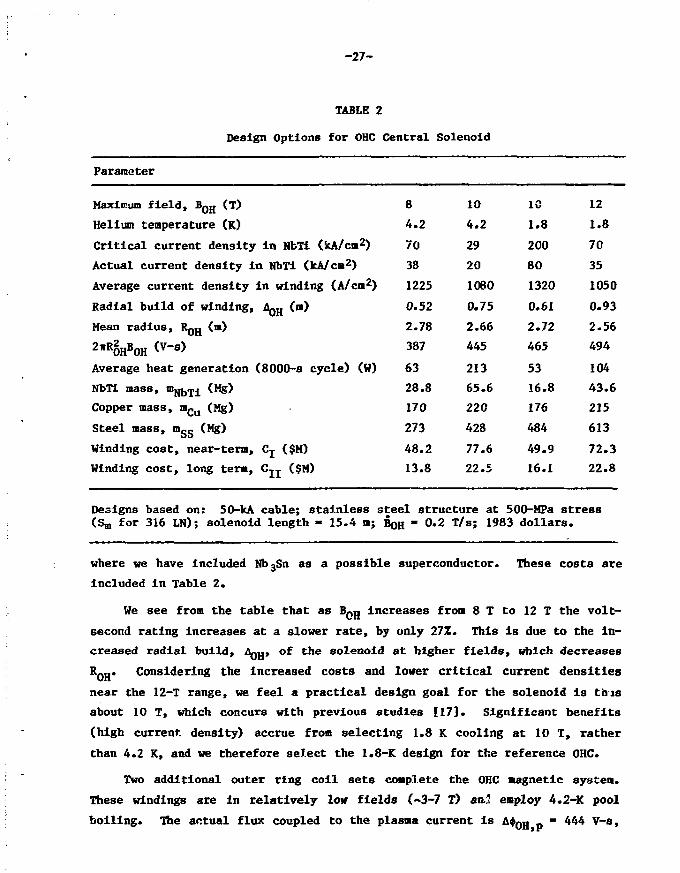
the 8-m reactor in order to select the maximum practical solenoid field, B Q H.
The designs are summarized in Table 2.
In formulating costs for magnets we note that there is often wide dis-
agreement in cost estimates for these items, as would be expected for an in-
dustry which is still In its infancy. Therefore, we estimate costs on two
different bases. If we consider current material costs and fabrication tech-
niques [24] we find fairly expensive magnet costs; including wire and cable
production, fabrication, and winding we estimate this as
where m^ is the required mass of the various magnet materials. However, if
tokamak reactors are commercialized we would expect significant price reduc-
tions due to. mass production and learning experience. According to Ref. 1 we
can predict future technology to provide
16.7 $234— x »Nbsn x . — - 'kg kg
-27-
TABLE 2
Design Options for OHC Central Solenoid
Parameter
Maximum field, B Q H (T)
Helium temperature (K)
Critical current density in NbTi (JcA/cm2)
Actual current density in NbTi (kA/cm2)
Average current density in winding (A/cm2)
Radial build of winding, AQ H (m)
Mean radius, RQH (m)
2*ROHBOH <V'S>
Average heat generation (8000-s cycle) (W)
NbTi mass, n>NbTi (Mg)
Copper mass, mC(J (Mg)
Steel mass, fflgg (Mg)
Winding cost, near-term, Cj ($M)
Winding cost, long tern, CJJ ($M)
8
4.2
70
38
1225
0.52
2.78
387
63
28.8
170
273
48.2
13.8
10
4.2
29
20
1060
0.75
2.66
445
21365.6
220
428
77.6
22.5
1C
1.8
200
80
1320
0.61
2.72
465
53
16.8
176
484
49.9
16.1
12
1.8
70
35
1050
0.93
2.56
494
104
43.6
215
613
72.3
22.8
Designs based on: 50-kA cable; stainless steel structure at 500-MPa stress(Sm for 316 LN); solenoid length - 15.4 m; BoH - 0.2 T/s; 1983 dollars.
where we have included Nb3Sn as a possible superconductor. These costs are
included in Table 2.
We see from the table that as B^g increases from 8 T to 12 T the volt-
second rating increases at a slower rate, by only 27Z. This is due to the in-
creased radial build, AQH» of the solenoid at higher fields, which decreasesR0H* Considering the increased costs and lower critical current densities
near the 12-T range, we feel a practical design goal for the solenoid is this
about 10 T, which concurs with previous studies [17]. Significant benefits
(high current density) accrue from selecting 1.8 K cooling at 10 T, rather
than 4.2 K, and we therefore select the 1.8-K design for the reference OHC.
Two additional outer ring coll sets complete the OHC magnetic system.
These windings are in relatively low fields (~3-7 T) an.2 employ 4.2-K pool
boiling. The actual flux coupled to the plasma current is A+0H p - 444 V-s,

-28-
slightly less than the 465 V-s of the ideal infinite solenoid. These ring
coils require 12.3 Mg of NbTi, 101 Mg of copper, and 276 Mg of steel if a
stress level of 500,MPa is permitted; this represents additional winding cost
of Cj - $29.8 M or CIX - $9.5 M. We estimate the helium vessel to cost <-$3.1
H for the whole OHC system.
We find, thus, there is a cost penalty of at least ~$30-80 M for any burn
cycle requiring a full OHC system. Moreover, the 10-T OHC stores 16.6 GJ of
energy when fully charged, and this translates co expensive electric power
handling costs for the OH and hybrid burn cycles, as we shall see.
We next inquire regarding the impact of mechanical fatigue on the OHC
performance. Below a stress cycle lifetime of N o «• 3 x 10⁴ the steel bands
are sized for a stress level of Sm - 500 MPa (the lesser of two-thirds the
yield stress and one-third the ultimate stress for 316 LN at 4.2 K). Fatigue
data for steel [6] indicate that the stress levels must be reduced to guaran-
tee survival for a larger number of cycles. Since stress is reduced by in-
creasing the thickness of the structural steel bands holding the OHC together,
there are two detriments associated with an Increasing N0. First, the OHC
cost increases; and second, the solenoid winding increases in thickness,
reducing RQH and the flux <J>0H . These trends are displayed in Fig. 11, using
a safety factor of twenty on fatigue cycles. For N > 5 x 10⁵, where the
strain amplitude is e < 0.001, the lifetime becomes insensitive to N . For
high cycle lifetimes the increase i'n OHC cost is substantial, ~50-70Z more
than the base cost. The decrease in transformer flux at high cycles (~7£) is
not as significant for the S-n reactor as it would be for a reactor with a
smaller major radius operating in the OH cycle. We assume that any resis-
tivity increase due to work hardening of the copper stabilizer can be removed
by annealing during machine warm-up periods. We note that fatigue data for
NbTi composite and multi-strand cable are unavailable, and additional unpleas-
ant surprises could appear after long-term experience with highly pulsed
coils.
4.2 Equilibrium Field Coils
Reference EFC configurations were developed for both the 8-m and 7-m
reactors. The 8-a device Imposes two constraints on the EFC system — the EFC
should be decoupled from the OHC (zero mutual inductance), and EF coils are

-29-
200
I
om
iCMO
CM
100
0
I I i I I I t i M 11
I I I I I I I I I I I I I I I I I M l
120
100
80
60 S
oo
40
20
10°
Fig. 11. Complete OHC winding cost ($1983) and approximate flux versus
cyclic life; B Q H = 10.0 T, Rfl - 8.0 m, 316 LN structure.
restricted from the central hole, which is occupied by the OHC. This results
in a system with substantial stored energy, UEF - 6.36 GJ, a large coil vol-
ume, Vgp - 177 m3, and relatively small coupling to the plasma, $__ » 71
V-s. On the other hand, burn cycles without an OHC offer relaxed constraints
on the EFC design. For the 7-m reactor an attractive EFC system can be
designed: VE F
5.61 GJ, V g F - 136 m3, andVgF - 95 V-s. Comparing the
reference EFC systems for the 8-m reactor (with OHC) and the 7-m reactor
(without OHC) we see quantitative advantages of the latter configuration,
which are mainly due to the ability to locate an EF coil near the inboard mid-
plane. These advantages are not large, however, since the 7-m reac >r has che

-30-
hlgher plasna current (In order to achieve comparable performance with the 8-a
reactor). The advantages of Inboard coll placement are greatly magnified,
though, if a more highly triangular (d ;> 0.5) or "bean"-shaped equilibriun is
desired. The strong increase of stored energy with triangularity Is well
known [25]. Thus the stored energy and EF power supply costs for the 8-tn
reactor in this study mist be viewed in the perspective of the rather mild
triangularity (d * 0.2) selected for the plasna equilibrium.
Next we evaluate the EFC cost and lifetime. As in the case of OHC, the
cost of the conductor and structural materials for the EFC is estimated for a
50-kA cable design. The cable configuration is assumed to be helium-I (4.2 K)
pool-boiling coils with niobium-titanium and copper stabilizer (same as the
OHC outer ring coils). The cost of the EFC for the 8-m reactor is based on
material requirements of 170 Mg of copper sad 14.7 Mg of NbTi; In the absence
of fatigue, 689 Mg of steel is needed to achieve stress levels of Sm =• 500
MPa. Figure 12 shows the increase in EFC cost to accommodate increased
100
80
~ 602
en 40Oo
20
0
T T 1 I I I I II 1 I I I M i l
0*5
Mil l I i t i i ml iIO4 io5
i i ii nilI0 6
Fig. 12. EFC winding cost ($1983) versus cyclic life for full field swing (OH
burn cycle) and half field swing (hybrid burn cycle); 8-m reactor,
316 LN structure.

-31-
mechanlcal fatigue at large Na. We recall that hybrid burn cycle reduces the
vertical field BgF to about one-half the full field value, so stress varia-
tions are only approximately three-fourths of the variation experienced with
the conventional OH cycle. This accounts for the less expensive structure and
overall cost displayed in the figure. Finally, we note that the IT burn cycle
may require a still more expensive EFC since B E F must increase during the
overdrive phase above the values required for OH operation.
4.3 Toroidal Field Coils
For the purposes of our burn cycle study we use a simple constant-tension
D-shaped TF coil model [26]. The results, in Table 3, show the winding costs
to be similar for both the 7- and S-a reactors.
TABLE 3
Reference TFC Systems
Parameter
Maximum field, Bw
Inboard leg, Ri
Outboard leg, R2
Number of coils, N^pg
Full perimeter, L
NbTi mass, ^JJ,JJ[
NbjSn mass, mjjjjgn
Copper mass, mCu
Co-wound steel, m s s
Winding cost, long-term, CJ-J
Radial build (helium vessel}, A™
Coil width (helium vessel)
Helium vessel thickness, tHe
Unsupported length
Maximum bending moment, M m a x
Shear panel, height x width
Force on shear panel
8-m reactor
9.81 T
4.06 m
14.15 m
12
39.0 m
54.6 Mg
1.78 Mg
2122 Mg
1717 Mg
$109.9 M
,, 0.75 m
2.13 m
4.0 cm
11.85 m
131 MN-m
9.61 x 4.00
62.1 MN
Designs based on co-wound steel structure atconstant tension shape: 1983 dollars.
7-m reactor
11.2 T
3.19 m
13.02 m
12
39.3 m
45.6 Mg
4.60 Mg
2130 Mg
1660 Mg
$107.3 M
0.94 m
1.67 m
4.0 cm
11.39 m
103 MN-m
m 9.63 x 4.03 m
79.8 MN
550 MPa;

-32-
The principal burn cycle related differences In TFC designs arise from
out-of-plane forces generated by OHC and EFC current variations. The thick-
ness, t , of the steel vacuum dewar which surrounds the helium vessel is a
variable in our study which is adjusted to provide adequate stiffness of the
unsupported span of the TFC against fatigue failure. Likewise, the thickness
of the shear panel, tg, is selected to provide fail-safe resistance to the
overturning torque on the TF coils.
In order to select the required thickness of the vacuum tank to limit the
fiber stress on the side v/all, a crack propagation analysis of the steel case
is undertaken. Standard fracture mechanics [27] methods are used to predict
the crack width, a, as a function of the number of stress cycles N . The
variable stress intensity is proportional to the maximum stress during the
cycle and to the square root of the crack size, Alt = 1.2 Fo,,/ita. The factor F
depends on how the stress variation compares to the maximum stress. For exam-
ple, fully cyclic stress, from +a^ (tension) to an equal but opposite stress,
-crM (compression), is more damaging than cycling between oM and zero stress.
We use the damage model which characterizes most metals [22], F = (l - R ]"» t̂
s
with Rg = om/on, am being the minimum stress. Figure 13 displays the maximum
permissible stress for a given number of cycles to failure for various initial
cracks, a0, assuming safety factors of two on stress and four cycles, for room
temperature annealed 316 LN [6] . We see that, for typical aQ> tens of thou-
sands of cycles to failure occur for aM - 200 MPa. Generally, higher ov. is
permissible if a smaller number of cycles is specified. In any event, the
stress should not exceed Sm, which is 217 MPa at this temperature. Thus,
there are no significant reductions in structural requirements for the TFC
once the total number of vertical field cycles is reduced below about ten
thousand.
The stress variations are quite different among the tokamak burn cycles
we consider. For the hybrid and internal transformer modes B E p typicallycycles between full and half-field values, so R = 0.5 and the bottommost
s
abscissa can be used. Note that each stress cycle corresponds to one fusion
burn cycle in this case. In the single swing OH burn cycle the OHC is reset
to the same polarity before each burn, so the plasma current always flovs in
the same sense, the out-of-plane force is always in the same direction and Rs
= 0. The figure shows, from the middle abscissa, that fewer cycles to failure

-33-
10'1
'051
107
I03 I04 I05 !06 !07 IOe
7N,(Rs=-l,D0UBt£ SWING)
N,(RS=O,SINGLE SWING)
N<r(R$=0.5.HALF SWING)
Fig. 13. Fracture mechanics limited stress, 316 LN (annealed) at 293°K.
can be tolerated under these conditions compared to the half swing. The worst
situation obtains if B Q H swings both directions, reversing toroidal current
and OHC polarity on alternating fusion periods. Then Rg = -1, and even fewer
stress cycles are tolerable than for single swing operation of the EFC. Note,
however, in this mode two fusion burn periods occur for each mechanical stress
period.
Controversy exists over what initial crack sizes should be considered for
failure analysis. Conservatism dictates the choice of relatively large aQ,
since inspection of the fabricated steel structure becomes expensive and un-
reliable for small flaws. Moreover, the failure to detect an initial crack
could have serious consequences; even though TFC monitoring is advisable,
periodic remote inspection will prove challenging, and replacement of a
weakened TFC with a growing crack may prove impractical. On the other hand,
inspection techniques may not differentiate between harmless stress risers of
dimensions a (for example, bubbles) and true cracks. In this case fracture

-34-
mechanics could severely underestimate the cycle lifetime of the steel struer
ture. With these caveats In mind we proceed to use fracture mechanics with
initial crack lengths assumed to be one-tenth the thickness of the vacuum
tank, aQ » 0.1 x ty.
The free span of the TFC is treated as a straight, rigid nested box
beam. The moment of inertia of the helium vessel,. Ijje» is found and that of
the vacuum tank, 1^, is found for various tank wall thicknesses. The total
moment, IHe + Iy, is used to infer the fusion cycle lifetime; from the dewar
thickness, ty, the volume of steel (hundreds of cubic meters) and cost of the
vacuum tank are determined. In our analysis we take the beam to be simply
supported at both ends. (This treatment yields close agreement of maximum
bending moment and out-of-plane deflection when tested against the finite ele-
ment analysis of Ref. 6.)
The cost of the vacuum tank, based on $24/kg (the estimated cost [6] in
1983 dollars) is shown in Fig. 14. As expected, the cost is level up to Nf
-• 101*. Hence, a reactor with a day-long burn (tf ~ 105 sj has a vacuum tank
no more expensive than that of a CW reactor (Nj «• 200, t£ ~ 3 mo). However,
shorter burns accumulate fatigue damage very quickly. For short burns [t^ ~
1()3 S, NJ *• 10^J the incremental structural costs become prohibitive. We cau-
tion, though, that our cost estimates may be too high at large Nf. At tank
costs of $100 M to $200 M the steel side walls are in the range of 20-cm to
30-cm thickness. It may prove impractical to form such large, thick members.
The prohibitive costs at this point would drive us to consider alternative
structural support. For example, an intercoil support structure might be used
in order to drastically shorten the unsupported free spans of the TFC, perhaps
reducing costs by large amounts. So we must conclude that the particular
model (patterned after STARFIRE) used in our present study may become inappro-
priate for TFC structure experiencing millions of lifetime cycles.
We note that there are large differences among the burn cycles for a fixed
Nf. The double-swing OH cycle has the largest stress fluctuations and hence
requires the most massive structural support. For the same Nf a single swing
OH cycle results in cost savings. Even more attractive is the hybrid burn
cycle, since the stress fluctuation is so modest (Rg = 0.5). For IT opera-
tion the relatively small stress fluctuations are overshadowed by the much
larger number of pulses envisioned for the life of the reactor (N > 106),f ~

-35-
300
200
<<<»•
COoo
100 —
^—VACTANKSHEAR PANEL
I03
IT
K HYBRID
I06 10'N
Fig. 14. Structure cost for TFC vacuum cases and shear panels.
Box Indicates CW, 7-m reactor.
with the net result that this cycle is likely to be the least attractive in
terms of TFC structural costs.
As with the vacuum tank a fracture mechanics life analysis can be per-
formed for the shear panels. The cost of the shear panels for various burn
cycles is also shown in Fig. 14. The cost trends exactly parallel those for
the vacuum tank, but their magnitude is considerably smaller.
We see that a single swing OH cycle operating with a one-hour burn (Nf ~
3 x 10⁵) will entail capital costs at least $100 M higher than a reactor
operating in the CW mode. This disparity Is greatly reduced if the ohmic burn
period can be extended to 8 h or more. If neither of these options is availa-
ble but a hybrid burn cycle is used, then any fusion cycle period exceeding
about 30 min becomes competitive. The internal transformer cycle seems
unattractive since it has such a tremendously large total number of cycles in
the reactor lifetime (Nf > 106). A completely different design philosophy
would be required to accommodate coil fatigue in such a case.

-36-
Last, we address the problem of eddy current heating In the TFC system.
The dominant heat source is due to poloidal field component variations normal
to the cryogenic steel structure encasing the winding, the 4-cm thick helium
vessel. Following the method of Ref. 28 we find that the heating per length
along the TFC helium vessel is dP/dA « L (3 )2/p, where IHe is the out-of-
plane bending moment of inertia, and where p is the case resistivity. We find
numerically that the electric refrigeration power is nearly always negligible
in the reactor's power balance. Likewise, capital cost for refrigeration is
quite small compared to the overall power plant cost. We thus conclude that
burn cycle alternatives have a relatively small impact on the reactor cost and
performance from considerations of eddy current heating.
4.4 Blanket Thermal Effects and Thermal Energy Storage
Of two viable breeding blankets studied, one with a solid breeder and
water coolant and one with self-cooled liquid lithium, only the former is In-
vestigated with a detailed burn cycle analysis [6]. He consider a model burn
cycle with a 1-h burn, 10-s linear power decrease, and a variable dwell
period, t^w, followed by a 10-s power increase. Explicit blanket temperature
variations are calculated for four cases: t̂ = 0, 30, 90, 200 s. During the
burn the wall load is set at Wn - 3.45 MW/m2.
The solid breeder blanket contains Li2O granules and is punctuated by ten
rows of cooling tubes designed ro maintain (steady-state) temperatures between
410°C and 3OCTC in the breeder. Coolant inlet/outlet temperature is 280°C/
320°C. Experience shows that an acceptable assessment of this system can be
carried out with results based on only three representative blanket regions.
We calculate the transient temperature response near the first wall (100% of
the nuclear power density, 41 W/cm3), at the 257. power region, and at the back
of the blanket (5% power). Since the volume of the blanket region associated
with each coolant channel in an exponentially decreasing nuclear power field
increases as the blanket regions are located further away from the first wall,
the thermal inertia of regions in the radial direction (depthwise) increases.
Our results agree rather well with a simple model proposed by Deis [29]. As
expected, the changes in the coolant outlet temperatures and temperature
gradients in the Li20 blanket increase as the dwell times increase. If the
dwell times are sufficiently long (> 200 s), the temperatures of components
are found to decrease to the coolant inlet values.

-37-
Thermomechanlcal fatigue may not be critical to the porous LigO mass,
which is fabricated at only 85% of theoretical density. Cooldown of the
breeder below its lower operating limit can affect tritium recovery, but this
may be unimportant if the duty factor is high. Thermal stresses across the
coolant tubes during power transients (<5 MPa) are much less than the primary
stress (~55 MPa) due to the high pressure coolant (at IS MPa) so fatigue is
insignificant. Dimensional changes are possible at the breeder/cooling tube
interface after cyclic operation. Although this could adversely affect the
thermal conductance at the interface it might be controlled with a metal felt
sleeve around the tube. In all, no severe degradation of the blanket life is
anticipated due to cyclic operation.
Although, due to their lower thermal inertia, the high power blanket
regions have faster time response and larger temperature fluctuations than the
low power regions, these differences are averaged as the water flows from the
cooling tubes and is mixed in the headers leading to the steam generators.
Figure 15 displays the mixed coolant temperature for one case, t^w = 30 s.
Note the temperature drops steadily for 40 s to 304°C but requires several
minutes to recover once nuclear heating returns. Even for t^w • 0 s (10-s
power drop followed by an immediate power ramp), the limiting case for IT
operation, the coolant drops to 313°C- Since the electric power is propor-
tional to coolant temperature rise in the blanket, we find the generator
output drops transiently to (313-280)/(320-280) - 83% of its steady state
rating even with this shortest dwell. Moreover, the whole power conversion
system [1] is based on coolant outlet temperatures of 320°C which generate
slightly saturated steam (299°C at 6.3 MPa), so coolant temperatures below
~3004C result in wet steam at 279°C entering the turbine. Both steam tempera-
ture fluctuations and moisture content are damaging to the turbine blades, but
this may not be critical if the burn cycle's duty factor is very high. We
assume the dominant concern is the transient electric output of the fusion
power plant. Hence, we oust provide an energy storage system which supplies
the whole energy deficit during the dwell with a fast time response to keep
the electric power constant.
For a 4000-MW thermal reactor, the energy deficit varies from 40 GJ to
over 800 GJ as tdw varies from 0 s to 200 s. Several thermal storage systems,
such as packed columns of metals or ceramics, and chemicals, were considered

-38-
324
321
318-
O 315-
(XL
a:
f—
312
309
306-
303
300 -7000 7200 7400 7800 7800 8000 8200
TIME <S>
Fig. 15. Volumetric average temperature response: 30-s dwell.
for energy storage. However, they did not appear to be practical if the
thermal energy is to be withdrawn in a relatively short period of time.
Energy storage in pressurized water, which can be withdrawn as steam by flash-
ing [30j, or energy storage in a high temperature liquid metal which can be
fed into a heat exchanger/evaporator unit appear to be practical, although
such systems are considered to be at the upper end of existing technology.
Analyses show that a pressurized water/steam system is suitable for the solid
breeder blanket, and a hot sodium reservoir would be practical for the liquid
lithium blanket. A detailed description of the two systems is available in
Ref. 6, and the component costs are summarized in Tables 4 and 5.

-39-
TABLE 4
Cost of Thermal Storage System: Water-Cooled L±20 Breeder
High pressure vessels (@ $14 M each)
Charging pumps
Piping
Valves
Condensate storage
Instrumentation and control
Building and structures (incremental)
Installation
Total
Basiccost
28
10
5
8
5
5
4
8
71
Cost ofadditionalcomponentsfor 10~s dwell
28
1
1
1
2
4
37
$M (1983).
TABLE 5
Cost of Thermal Storage System: Self-Cooled Lithium Blanket
Storage vessels
Sodium charge
Piping
Valves
Building and structures (incremental)
Gas blanket and emergency venting
Sodium cleanup system
Instrumentation controls
Installation
Miscellaneous
Total
Basicunit
6.5
0.3
3.6
7.1
2.6
1.2
2.0
3.0
4.0
2.0
32.3
Cost ofadditionalcomponentsfor 10-s dwell
6.5
0.3
1.8
4.01.5
0.6
0.6
1.2
1.5
1.0
19.0
*$M (1983).

-40-
In comparing burn cycles we base thermal storage costs on the results in
the tables; for the water/steaa and lithium/sodium/steam systems we have res-
pectively
CH20 " $?1M+ t$3*7 M * W 0 ]
Cjja = $32 M + [$1.9 M x tdw(s)] .
Examination of the cost of thermal storage for the two systems indicates that
the costs for the liquid-lithium breeder is significantly lower. The primary
reason for the low cost of the liquid-metal system is due to low-pressure
operation of the thermal storage system (1.5 MPa liquid-metal breeder versus
15 MPa for water-cooled solid breeder). It should be noted, however, that the
liquid lithium blanket was studied in less detail; the added cost of tritium
containment such as double-wall pipes, penalty for heat exchangers due to
added thermal resistance of double-wall pipes, tritium cleanup, and recovery
systems have not been included in this analysis. Although thermal energy
storage is rather cheap (~$1.0 x 10~3 — $5.0 x lO"1* per joule) compared to
electric energy storage, it appears to be a major cost item for pulsed burn
cycles due to the tremendous energy storage required for long dwells.
4.5 Auxiliary Power for Heating and Nonlnductive Current Drive
Dynamic simulations of reactor startup suggest 75 MW of plasma heating
for tgp ~ 5-10 s is adequate for ignition. We assume the same power source
(ECRH, ICRH, etc.) can be used for both heating and current drive, and, thus,
we assign a cost penalty for noninductive current drive only for that portion
of absorbed power which exceeds 75 MW.
The capital cost for high power rf equipment is difficult to estimate,
for several reasons. First, Ctf power systems exceeding 100 MW have not been
built, so learning curves and economies of scale are hard to predict. Also,
some technologies (ECRH) are not advanced to the point that high power CW
sources are available. Likewise, system costs are sensitive to requirements
auch as mode purity, tunability, bandwidth, launcher design, radiation and
electrical protection, and transmission efficiency. In Fig. 16 we display
curves of estimated capital cost versus power launched into the tokamak, for

-41-
1000
0.2 I 10 100
INJECTED POWER (MW)Fig. 16. KF capital cost modeling and data. Specific designs are
denoted by boxes for ECRH, circles for LHRH, and triangles for
ICRU; point A is from Fef. 16 and B and C are from Ref. 17.
three frequency regimes, The isolated points represent existing or near-term
systems at the 1-MW level and published fusion designs (see, e.g., Refs. 31
and 32) at the 100-MW level; the scatter among the points Indicates our level
of uncertainty In cost estimates.
Regarding the overall power transfer efficiency, T)J» °f rf systemc we
find from a literature survey that the ac-to-rf efficiency could vary from a
low of ~23% for ECRH to a high of ~55% for LHRH and ICRH. This relatively low
rijj figures promlnantly in the economics of the CW burn cycle.
4.6 Electric Power Supplies and Energy Storage
The type and cost of electrical components for a tokaaak depend on details
of the burn cycle. In particular, power supply costs generally decrease as
the time between burns increases since the magnets can be energized over

-42-
longer periods. Countering this is the trend to more expensive thermal stor-
age as the dwell period Increases. In this section we explore this tradeoff
to identify the optimum operating parameters for each burn cycle, including
the cost of a noninductive current drive system when applicable.
The double-swing OH burn cycle is studied first. Bz-sad on a detailed
analysis of the burn cycle of the 8-m reactor with a profile-averaged time-
dependent plasma code, general features and operating algorithms were
developed for use in the parametric burn cycle study. Additional insight to
the power supply aspects of tokamaks Is available in Ref. 33.
The circuit diagram for the OH cycle is shown in Fig. 17. As shown in
the figure the OHC is driven by two types of energy transfer devices. A dtnnp
resistor/SCR switch system is used for startup to ramp down the Initially
charged OHC in the Ohmlc heating time, tQJi. This resistor could probably be
of the nonlinear type, e.g. zinc oxide, or silicon carbide as proposed for the
TFTR- OH system [34]. The resistor is modeled as having an ideal, i.e. con-
stant, voltage drop, when connected. The same resistor is also used for the
shutdown. During the burn period the OH current is slowly ramped up to make
up for resistive losses in the plasma. The power needed to do this is rela-
tively small, ~15 MVA. Finally, after shutdown, the OH coil must be recocked
to the full 10-T value for the next burn pulse. This is done in the dwell
period, t,jw. During the dwell period the plasma chamber is evacuated and then
filled with fresh deuterium-tritium gas for the next burn pulse. The recock-
ing OH power supply is a rectifier/invertor SCR-type supply operating out of
an MGF set. The cheapest way to recock the coil, which stores ~17 GJ at full
field, is to alternate the direction of induced plasma current every pulse.
We recall however, that this double-swing current: mode aggravates the toroidal
magnet fatigue; thus, the power supply cost saving might be offset by the need
for a more expensive TFC system. Another cost saving technique is to use the
same OH recocking SCR supply to drive the EF coil during startup and shutdown
and the OH coil during the burn phase. The SCR power supply requirements are
then set by whichever system, EF or OH, has the maximum power needs. A low
density startup, together with initial rf heating, is used to minimize resis-
tive volt-second losses. Thus the plasma is kept fairly hot throughout the
Ohmic heating portion of the cycle. The resistive volt-second loss during
startup is typically 5 V-s.

- 4 3 -
TRANSFERDEVICE
OH CIRCUIT PLASMA
TRANSFERDEVICE
EF CIRCUIT
TRANSFER DEViJES :DUMP RESISTOR-SWITCH
I(USED FOR OH COIL)
MGF SET(USED FOR OH a EF COILS)
SCRRECTIFIER/INVERTORPOWER SUPPLY
Fig. 17. Power supply system for a conventional OH cycle. Cycles with
noninductive current drive have an additional (rf) current
source in the.plasma circuit and have no dump resistor; more-
over, the IT and CW cycles have no OH circuit.
The second phase of the startup is defined as the EF ramp. During this
period the plasma is heated to ignition and the EF current is brought to its
full value. Throughout the startup the EF current is raised to maintain the
plasma in MHD equilibrium. The EF power requirement is given by the product
of the maximum EF voltage and the maximum current. In order to minimize the
EF voltage during startup, the rf heating is modulated to maintain a fixed
rate of net heating power during different portions of the cycle. In addi-
tion, xenon is added towards the end of the startup to establish plasma
thermal stability.

-44-
For the 8-m reactor a burn time of -51 min can be obtained, based on the
OH flux swing of 307 V-s available for the burn period and assuming a plasma
loop voltage of ~0.10 V (Spitzer resistivity with an anomaly factor of 2.5 due
to, e.g., trapped electrons).
We find the following approximate formulas describe the energy transfer
system (ETS) requirements in general:
,max
OH
*•nP0H
PEF
max
0.75
= 71
A+dump ;
rP* , P
max^ O H
where PQH IS the reactive power Isolation requirement of the dump resistor/-
swltch, PQH IS the OH recocklng requirement, PEF is ^ e EF reactive power
requirement (for tgp < t 0 K), and Pmax i s t h e reactxve power requirement of the
SCR supply used for both OH recocklng and EF drive. Fmax is also the require-
ment of the generator portion of the MGF set. The other parameters are IggX
= 163 x 106 A, Aij)dump - 163 V-s, and UEF - 6.36 GJ. The stored energy
requirement of the MGF set is approximately constant, at ~30 GJ. Finally, the
thermal storage system time requirement is given by:
tdown = 2 c0H + CEF + tdw *
This downtime is the time over one burn cycle when no fusion power is pro-
duced, considering the fact that there is some fusion power during the EF
ramp-up and ramp-down periods.
The power supply cost algorithms [33], based in part on TFTR experience,
are (in 1983 dollars):
COH

-45-
$0.1CSCR + °MGF ' ~~ x Pmax + $70 M ,
where C 0 H is the cost of the dump resistor/switch and C m a x is the comb-ined
cost of the SCR supply and the MGF set. The thermal storage cost is a
generalization of our previous result, CgT = C or CgT = ^ a * w^ e r e cdw i n
Sec. 4.4 is replaced by (t<jown - 10 s). The total ETS cost is thus: CE T S
COH + Cmax + CST*
A wide range of OH burn cycle parameters was examined. It was found that
a choice of tQjj * tjjF is about optimum for a fixed value of t^w> The result-
ing ETS cost for this parameterization is shown in Fig. 18 for the H2O thermal
storage system. The results show graphically the tradeoff between the p<- er
supply and thermal storage costs. At short dwell times, £10 s, the recocking
supply requirements become very high and dominate the cost. At longer times
the increase in thermal storage cost offsets any savings in the power supply.
For a given value of t,.,, there is a broad minimum in cost for a 20- to 30-s
dwell time. For the values of tQH = CEF = 10 <s and t d w = 20 s the ETS cost is
~430 M$ for tne H<>0 system. Thus the ETS cost is a substantial fraction of
the total reactor capital cost.
Similar curves are obtained if the lithium/sodium thermal storage system
is chosen [6], except all costs are ~$100 M less than those in Fig. 18. The
best result in this case has C^g = $309 M with tQH = t E p = 10 s and tdw =
30 s. Hence we conclude that the advanced technology of liquid-metal thermal
storage may result in substantial cost savings if a tokamak reactor must
operate in a cyclic manner.
We consider next the hybrid cycle, which uses an OH coil to maintain
plasma current during the burn and a noninductive current driver to maintain
current during a period of time when the OHC is recocked. Similar types of
power supplies are needed for the hybrid cycle as the conventional system
except that an OH dump resistor is not needed. The toroidal current, I, is
related to the noninductive current component, 1^, and the OHC current,
and EFC current, 1 E F, by the following equations:
V0H " L0HI0H "
Id + (-Li +

-46-
900
800
COoo
i l l
400 4015 20 25 30
DWELL TIME,s —
Fig. 18. Energy transfer system cost for a conventional OH double-swing
cycle as a function of cycle parameters for a water thermal
storage, system.
where the M's denote the respective mutual inductances and with the toroidal
self-inductance constant. During the OH recocking phase 1 = 0 and I™ 0.
The required value of voltage needed to recock the OHC in the dwell time
period Is then given by:
OH
yOH,p
udw

-47-
and the OH power required for recocklng Is
P0H "
The required value of 1^ needed to maintain a constant toroidal current during
the recocking phase Is
id = i - ^ .
R
where the relation MQJ, * LQJ, has been used.
For Illustration we consider high-speed current drive, which has a driver
power requirement given by P^ = I^n^g/Y, where we assume the density n'.
during the recocking phase is much lower than during the burn. Combining the
expressions above we get the driver power in terms of y and the dwell period:
IA<|)OH J2!kP<|)OH J
R Cdw'
Thus the driver power depends linearly on the density during the recocking
phase and also depends strongly on the plasma resistance during this phase.
Obtainable values for these parameters, as well as y, are uncertain. A brief
analysis with our dynamic plasma code suggests n^Q - 0.02 and R = 100 nil = R'
seem plausible.
The value of I during the dwell period Is lower than for the burn period.
This is because the reduction in EF current, necessary because of the reduc-
tion in plasma g, during the density ramp-down phase, reduces I. Conversely
when the density is ramped back up, Igp increases and ramps I up to its full
value. Fr6m our simulation results of the 8-m reactor the value of plasma
current during recocking was found t o b e I » 1 0 M A . = I J .
The hybrid cycle offers several options in regards to the OHC design.
One option, t"o be discussed first, is to design an OHC to give the same burn
time as a conventional cycle. Since the hybrid OHC is only used to supply
burn volt-seconds the OHC field strength for this option would be lower than
for the conventional cycle. An alternative option is to use a different value
of field to obtain a different burn time.

-48-
Xhe value of CH field needed to obtain a burn time the same as for the
conventional cycle is BQg » 6.53 T. This gives a flux swing capability ofA*OH,p = 30° v"s« T h e stored OH energy at full field is (6.53/10.0)2 = 43Z of
that for the conventional OH cycle, a considerable cost saving.
With the above parameters the required rf power is:
pd = 10 MB + 3-°° ,
Cdw
where we have presently assumed Y/n^o = l»0. For a value t^w • 30 s, for
example, Pd = HO MW.
An additional cycle parameter is tEp. The EFC reactive power is computed
as for the OH cycle, and the thermal storage costs are calculated as before,
except t(jown = tEF + tdfcT. Finally, the incremental cost of driver power is
taken to be C^ = ($1.5/W)(P<j - 75 MW); this is the cost of auxiliary power
above the 75 MW needed for ignition, assuming using a "typical" cost for rf
systems (Fig. 16).
By varying t»w and tgp the total cost of the ETS can be calculated ana-
logously to the OH burn cycle. Typical results are seen in Fig. 19, for Y/n£o
= 1.0, BQH = 6.53 T, and water/steam thermal storage. The solid curves are
and the dashed cure is Cg^s + CJ. The dashed curve indicates that one
would expect to pay a high price for recocking in short times, because of the
high rf power needed. At long dwell times the costs go up due to increases in
the thermal storage system cost. As with the OH cycle there is an optimum t^w
and tgp which minimizes Cp^S' however, the cost of driver power tends to push
the optimum tdw to longer times than for the OH cycle. The best case (for
Y/n20 = 1*0, BQH = 6.53) has tEp =* 13 s and tdw = 45.8 s, resulting in C E T g +
Cd = $371 M. This is ~$60 M less than the power supply cost for the OH cycle
with the same burn length, which is due mainly to the elimination of the dump
resistor and switch. As expected, considerable cost reductions are possible
if the lithium/sodium thermal storage system is chosen; in the best case Cgjg
+ Cd = $256 M for TT/n̂ o " l«0 and BQH - 6.53 T.
The cost variations for other values of Y/nJo and B Q H are shown in Fig.
20. For the conventional and hybrid cycles the burn time ^oH
for B n u = 4 T for the OH cycle since this Is the minimum field needed to

650
350
300.
T
-49-
T T• WITHOUT INCREMENTAL rf COSTWITH INCREMENTAL rf COST (at $I.5/W)
I15 30 45 6 0
DWELL TIME,s —75
Fig. 19. Energy transfer system costs for a hybrid cycle, water system;
B'OH 6.53 T, 1.0 A/W.
supply inductive volt-seconds for startup. We note for short burns (tf < 30
min) that the hybrid cycle offers large cost savings relative to the OH cycle.
At the other extreme we see the hybrid cycle offers the potential for longer
burns than the conventional cycle, which could perhaps ameliorate some
fatigue-related life limitations.
Turning to the IT cycle, we recall there is no OHC for this operating
mode so the ETS consists only of the EFC power supply (SCR and MGF) and the
therroal storage system. A fundamental parameter for the IT cycle is the
plasma current overdrive ratio defined as:

- 5 0 -
s• -
C0S1
700
600
500
400
300
200
100
n
1 ! i
rINTERNAL /TRANSFORMER/
- //fa— // / /l0
i i
i i
/^BRIO
CONVENTIONAL
I
1 10.2 A/W
^ ^
1 1
1—
^ 0 . 5 _
1.0 _00
—
—
—
—
|
10 20 30 40 50 60
. BURN TIME, MIN - —
70 80
Fig. 20. Energy transfer system cost as a function of burn time
and cycle type. [Includes incremental driver cost "
S1.5/W x (pd - 75 MW) where applicable.] Burn time
assumes 2.5 * Spitzer resistivity; all curves assume
water/steam thermal storage.
where Ii is the maximum plasma current used, Ij - IQ + 41. For the IT cycle
the plasma current is given by the current equations with ^>HtP * 0» and the
burn time is t- - At
plasma current is given by:
(L/R) in 8. During the current drive period the
where L/R' is the plasma time constant during the current drive period and I
is the plasma current at the start of the current drive period. IQ is some-

-51-
what less than IQ due to the EF ranpdown preceding the current drive period.
We find that the dwell time necessary to obtain a current Ij is given by:
The EF ramp period for the IT cycle is similar to that for the hybrid.
However, the EF stored energy is higher because of the higher plasma current.
The EF power requirement scales approximately as:
where UEp. is the EF energy corresponding to IQ. Neither the EFC design nor
the plasma MHD equilibrium characteristics at higher values of plasma current
were assessed for this study, but these may be serious issues for the IT cycle
if 0 is fairly large.
The final parameter for the IT cycle is the thermal storage requirement,
given by tj o w n « t^w + tEp. The cost algorithms used previously can be
applied to the IT system. Similar parameters to the hybrid cycle are used
where applicable: Io - 13 MA, Ij - 10 MA, L/R' - 171 *•, and L/R - 2236 s.
The results of a parametric analysis of the IT cycle using a range of
overdrive ratios from 8 » 1 to 2 are shown in Fig. 20. As shown, the IT cycle
is limited to about one-half the OH cycle burn time, even with a (large) over-
drive ratio of two. The cost of the ETS system depends on the current drive
efficiency. However, for any given value of Y/nJo. t n e E T S c o s t f o r t n e I T
cycle is always significantly more than the ETS cost for the hybrid cycle with
the same burn length.
We close this section by remarking how the IT or hybrid cycle may offer
cost reductions or possible extensions of tf such as to reduce fusion fatigue
cycles, Nf, relative to OH operation. Nevertheless, these cannot approach the
promises of CW operation, for which we find C £ T S = $10 M and Nf £ 200. The
relative attractiveness of CW versus pulsed operation depends partly on the
cost, Cj, of the driver system, which we examine in the next section.

-52-
S. OVEIALL BOW CTCLK COMPAKISOH: IBACTOft DBSIGR GOALS
For each burn cycle there are a number of factors (e.g., burn length,
current drive efficiency) which we consider to be variable. A consistent
comparison of burn cycles requires a simultaneous analysis of the various
capital costs and cycle-related life Units as these parameters are varied.
To this end we can isolate the several cost accounts of a tokamak reactor
which are functions of the burn cycle parameters and monitor the total cost
variation of the power plant.
Our costing is based on the STARFIRE accounting system ['], with all cap-
ital costs adjusted to 1983 dollars. The largest variable costs have already
been discussed in Sec. 4. The power supply and electric energy storage sys-
tems are based on conventional technology, and we expect to see no significant
reductions in unit costs beyond the values assumed. We find a factor of two
difference in thermal storage costs and an even larger discrepancy in esti-
mates of superconducting magnet costs. In order to bracket the level of un-
certainty in our cost estimates we include both the high and low cost algo-
rithms for thermal storage and magnet winding. (For all burn cycles the TFC
winding is only costed with the STARFIRE method, CJJ, however, in order that
the CW reactor's direct cost be essentially the same as that of STARFIRE.) In
addition to the magnet data in Figs. 11, 12, and 14, we find the helium vessel
coi.cs for the 8-m (pulsed) reactor OHC, EFC, and TFC to be, respectively, Cna
- $3.1 M, Cgp - $6.2 K, and C™ - $31.0 M; for the 7-n (CW) reactor these are
- 0, c"® - $4.8 M, and C ^ - $28.8 M. Our direct capital cost includes a
152 contingency allowance for all the variable cost accounts. For the reac-
tors with noninductive current drive we include a cost, CU, which accounts for
the driver, and, based on Fig. 16, we illustrate this cost with two Halts,
$1/W and $2/W. Finally, the balance of plant (blanket, shield, heat trans-
port, turbine, generator, buildings, etc.) is taken to be the same for all
burn cycles, C B O p • $1736.9 M. (In fact, C-.p should depend on factors such
as reactor thermal power and gross electric power, as well as details such as
neutron wall load and blanket/coolant type. All burn cycles have similar
thermal power and wall loads, and, more importantly, we are only interested in
the relative costs of the cycle-sensitive accounts. Hence a constant Cggp is
acceptable and mainly serves to place any cost variations in perspective to

-53-
the complete power plant capital cost.) In order to emphasize only the rela-
tive costs associated with different burn cycle choices, the summary illustra-
tions, Figs. 21-25, display the total direct capital cost normalized to the
STARFIRE value (1.00 = $2062 M, total direct cost of STARFIRE in 1983
dollars).
5.1 Conventional (OH) Cycle
Capital cost and net electric power for the OH cycle are displayed in
Fig. 21, assuming a 10-T external transformer is used with the 8-m reactor.
The fusion period on the abscissa can be varied according to the achievable
plasma resistance. The total cost varies mainly due to mechanical fatigue in
the magnets and thus decreases for longer burns (smaller N f ) . However, if
longer tf is achieved by geometry changes, for example larger major radius
[15,17], we can imagine additional capital costs would be incurred.
Consider first double-swing operation. The upper curve in Fig. 21 is the
cost estimate assuming water coolant/thermal storage and using the Cj formula
for magnet winding cost and, hopefully, represents an upper limit on capital
cost assuming relatively near-term technology. The lower curve includes
liquid lithium/sodium coolant/thermal storage and the more optimistic C__ mag-
net cost algorithm and so predicts the best case, lowest costs typical of
advanced technology and mass production manufacturing methods. For this
operating mode the numbar of stress cycles, N , for the TFC vacuum tank and
shear panels is one-half the number of fusion (thermal fatigue) cycles, Nj;
however, for the OHC and EFC, N - Nf. We caution that our results for the
TFC cost are unreliable for Nf > 2 x 10⁵ since the two-way stress fatigue is
so severe at this point that the STARFIRE TFC structure becomes unworkable.
Note that the capital cost flattens out for tf > 4 x \Qr* s <• 10 h. If tf - 16
h is possible and the electric utility is willing to operate the fusion reac-
tor as a peaking unit [17] (with diurnal electric power fluctuation) then an
additional $200 M-$300 H could be saved by eliminating thermal storage and the
M6F set. However, this would still be 15% more costly than the STARFIRE reac-
tor, due to the OHC and its attendant electric power supplies.
For single-swing operation N - N^ for both the TFC and EFC; however,
recocking the transformer for each burn now sets N a - 2 Nf for the OHC. The
increase in power supply costs for this mode more than offsets any reductions

-54-
io6 105
Nf
I04
Fig. 21. OH cycle; BQH = 10 T, 8-m reactor, (a) Upper cost curves
represent water thermal storage and near-term magnet costs
(Cj), and lower curves represent liquid sodium thermal storage
and long-term magnet costs (CJJ). Cost is total direct capi-
tal cost normalized to STARFIRE (Ref. 1) (b) Net electric
power, (c) Plasma resistance required to obtain tf, norma-
lized to Spitzer resistivity, R , with Z f f » 1.70, Tup* ~en * ~e10 keV, and 1Q » 13.0 MA. Solid symbols are burn goals for
worst case disruptions and thermal fatigue; open symbols are
goals for moderate disruption damage (circles « liialter's
leading edge, squares « limiter's front face, and triangles "
first wall).

-55-
(o)
0.01 1.0 I03
rl0) (A/W)
0.01 O.I 1.0-?*-
103
Fig. 22. CW cycle; 7-m reactor, (a) Direct capital cost for two values
of current drive system cost; EFC winding costed with Cir
formula, (b) Net power. Upper abscissa applies to high speed
current driver, and lower applies to low speed driver.
Note: T - 12 keV, n 2 0 - 1.9, I o - 14.8 MA.

-56-
oo
— 16005
I I
2.0
4000
2xl06lxl06
J L
5xlO5
N( FOR3xlO5
1.0
4xl062xl06IXIO6 7XI0 5
N, FOR
Fig. 23. IT cycle; S-n reactor; L/R" » 171 s. (a) Direct capital cost
based on water thermal storage and near-term magnet costs
(Cj), with current drive system costed at $1.5/W. Burn length
and magnet fatigue based on R = Rsp«
density phase, andsp«
refers to the low
Is in units of A/W. (b) Net power,
0.5. Lowest
abscissas denote lifetime cycles for given overdrive ratio, 3
but different plasma resistance R.
reflecting lower duty factor when R > Rspi <1,j

-57-
ou
1600
- 1400
I20Q
(b)
B0H(Wb/mz)
10
10
10
1too
11000
1 1
1200
12000
t,(s> FOR
1
13O0
(V-s)
l 03000
R/Rep = 2.5
l
1400
14000
2xl06lxl06 5XIO5 3xlO5
Nf FOR R/RSP=2.5
Fig. 24. Hybrid cycle; 8-m reactor, L/R' - 171 s, driver costed at
$1.5/W. (a) Direct capital cost based on water thermal
storage, near-term magnet costs (Cj); and magnet fatigue
with R - 2.5 R . (b) Net power. Top-most abscissa is
full field in the OHC solenoid.

-58-
o
- 1600
5 1400
1200
(b)
100
_L4 6
e 0 H {Wb/m2)
J I2OO 3OO
irwO__L
10
4 0 0
1I I I l n I I I G A' I I I I0 2 0 0 0 4 0 0 0 6 0 0 0 8 0 0 0 IxlO4
if (s) FOR R/Rgp'1.0
IKIO 6 1x10⁵N, FOR R/Rsp= 1-0
Fig. 25. Hybrid cycle: same as Fig. 24 except cost is based on
sodium thermal storage, long-term magnet costs, and
fatigue assuming R = Rom.sp
in the TFC fatigue with the result that single-swing operation appears more
expensive than double-swing operation.
For the OH cycle the duty factor is always large since tdown « so-— — — ,
the net electric power, Pnec exceeds 98% of the maximum possible for allvalues plotted.

-59-
Besides reductions in capital cost at long burns (tf 5> 10 h), noted
above, we recall that the first wall and limiter integrity are likely to
improve with longer burns. Referring to Figs. 8-10 we find tf £ 3000-7000 s
is desirable in order to withstand moderate disruption damage at Wn - 3.5
MW/ra2. In the event of severe disruptions t{ >. 1 x 101* - 3 * 104 s is
needed. We conclude that there are strong motivations for achieving tf in
excess of several hours for the OH burn cycle. However, for fixed reactor
size (Ro = 8.0 m) only modest extensions of t̂ (beyond one hour) may be pos-
sible, for example, by reducing Zgj£ or eliminating trapped electrons in order
to lower the loop voltage.
5.2 Continuous (CW) Cycle
For very efficient current drive the CW cycle ts exceptionally attractive
since several complete subsystems (OHC, MGF, dump resistor, and thermal stor-
age) are absent. The direct cost, as shown in Fig. 22, is much less than for
the OH cycle In the high efficiency limit. The cost in the figure includes
the noninductive current drive system, based on a price range of $l-2/W, in
accord with Fig. 16. Note that the required efficiencies for high speed and
low speed current drive, f and Y , are nearly equal at T = 1 2 keV.
Comparing Figs. 21 and 22 we find the CW cycle becomes competitive in cost
with OH operation once Y ^ \ 0.03 A/W.
Of course, circulating power is a major concern for CW operation. At
Y * 0.03 we see Pnet is very sensitive to the current driver system effi-
ciency. In fact, for the most credible range of r\, * 0.25-0.50 we project a
need for Y <£ 0.07 A/W in order to make the CW cycle appear reasonable.
Thus, roughly a four-fold improvement in Y is needed over the current
experimental results [11,12]. A breakthrough in driver technology could relax
this Y requirement somewhat; for example, Y^ £ 0.04 A/W is probably
acceptable if nd =» 0.70. Driver cost reductions (below $1/W) apparently are
not as important for a CW reactor as are improvements in t^ (above 0.50). In
the other limit of large Y^ or Y^ we note that the best theoretical values
("O.2 A/W and "0.16 A/W, respectively) attain almost all the potential advan-
tages of CW operation. At Y > 0.2 A/W there are no cost reductions since
we assume a minimum of 75 MW of auxiliary power is still needed (for igni-
tion). Above Y * 1.0 A/W we see increases in Pnet become negligible.

-60-
Lastly, we are reminded that the CW cycle has Nf » 200, so fatigue is not
a factor. This facet of the CW operating mode may give it a crucial advantage
over the pulsed nodes in the effort to attain high reactor availability.
5.3 Internal Transformer (IT) Cycle
Even if it is not possible to achieve Y ^ i 0.07 it may still be possi-
ble to reduce reactor costs below those for the OH cycle if the IT operating
mode is employed since the IT cycle dispenses with the OHC and its dump
resistor/switch. In addition, maintaining the toroidal current nearly con-
stant may reduce the likelihood of disruptions, although this is not guaran-
teed since density, temperature, and beta fluctuations do occur, and more
frequently than for the OH cycle.
The capital cost and power balance depend on the overdrive ratio, 9, and
the ratio of current drive efficiency to electron density during the overdrive
phase, Y/nJo* Additionally, the driver power is minimized by enhancing plasma
resistance during overdrive, and we find the most likely case has L/R" = 171
s. (In comparison, L/R = 5590 8 during the burn if R = RSp.) Finally, the
dwell and EFC ramp times are optimized to minimize the total ETS and driver
cost. The results for the total capital cost are given in Fig. 23 for the 8-m
reactor with water thermal storge and near-term magnet costs (Cj). The cur-
rent drive system is costed at $1.5/W, and the magnet fatigue is based on rea-
sonably long tf, assuming R = Rgp during the burn. We have every confidence
that noninductive current drive can achieve Y/nJo *n t n e range displayed. For
example, PLT has documented Y = 0.014 A/W (scaled from its Rg = 1.32 m to an
8-m reactor) with lower hybrid drive at n$o " 0*03 to attain Y/nJo = 0.47. We
note from the figure that there are only small benefits from increasing Y/n£o
beyond unity.
At small 6 ("1.2) this cycle offers large cost savings, with the cost
"1.25 times STARFIRE, compared to the OH cycle which, for R = RgP and near-
term technology, costs "1.38 times STARFIRE. At such small 9 the current
drive system is relatively small so the cost is insensitive to this cost
account. The cost savings result from the reduced ETS compared to that for
the conventional cycle (see Fig. 20). However, at 6 * 1.2 the critical
drawback for the IT cycle is the large increase in Nf compared to the OH
cycle. For example, with t̂ <* 600 s disruptions must be much less frequent

-61-
(f < lO"4) or less damaging than for the OH cycle (which has tf •> 6000 s) in
order Co withstand thermal damage to the first wall and limiter. Operation at
higher 8 still results in a larger number of fusion cycles than the OH operat-
ing mode and is also less credible due to the larger Al/i0 resulting from the
stronger overdrive* Indeed, all the cost figures are suspect in this figure
since fatigue is so severe for the TFC structure (cf. Fig. 14), i.e., it is
not clear that TF coils can be fabricated in the fashion utilized by STARFIRE.
The situation deteriorates If the resistance should be anomalously large.
For example, with R = 2.5 Rgp, Nf probably exceeds 1.0 x io6. This results in
a more expensive capital cost (due to Increased structure to withstand mechan-
ical fatigue) and probably a lower availability (due to more frequent failures
related to thermal cycles). In addition, the duty factor and net power suffer
significantly for increasing values of R, in contrast to the OH cycle.
5.4 Hybrid Cycle
This cycle appears more attractive than either the OH or IT cycles for
relatively low values of Y. We consider both Y/nJo an<* t n e ^H^ flux (°r»
equivalently, the OHC field, BQJJ) as variables. We set the current drive
system cost to be $1.5/W, but we find the total cost is insensitive to the
exact driver cost for Y/n^g i 1.0 or for B Q H £ 2 T. As discussed in Sec. 4,
the dwell and EFC ramp periods as well as the requisite current drive power
are determined by minimizing the ETS and current drive system cost.
Figure 24 shows the total cost with water thermal storage and near-term
magnet costs. It also takes the pessimistic assumption of high plasma resis-
tance, R • 2.5 Rgp, which results in relatively short burns and a large number
of fatigue cycles. We find, for the same burn length as attainable with the
OH cycle under these circumstances (t^ " 3100 s), the hybrid cycle is cheaper
than the OH cycle whenever Y/ngo ^ 0.3. This is because the OHC is smaller
and because the dump resistor/switch is absent. Since the toroidal current is
held nearly constant in this operating mode the frequency of disruptions might
possibly be somewhat lower than for the conventional OH burn cycle o If we
could permit, say, twice as many burn cycles (Nf ~ 6 x io5) with short t̂ -
1600 s, then we find even greater cost savings. For typical Y/n^o we find the
minimum total cost "1.25 times the STARFIRE cost, whereas the comparable
(water storage, near-term magnets) reactor operating under the OH cycle cost

-62-
"1.43 times the STARFIRE cost. On the other hand, if thermal cycling is a
particularly severe limitation to llmiter or first wall life we could opt for
slightly longer burns than the OH cycle allows. At BofJ = 10 T the hybrid
cycle achieves tj *" 4800 s compared to tj "• 3100 for the OH cycle, and if
Y/n£0 i 0.5 the hybrid case still results in a less expensive reactor.
Another significant conclusion follows from a comparison of Figs. 23 and 24,
viz., for any given burn length t^ in excess of ~1500 s the hybrid cycle is
always cheaper than the IT burn cycle. This steins from the ve^y high ETS cost
(see Fig. 20) incurred at large overdrive ratio 6.
The same conclusions are reached for the hybrid cycle with lithium/sodium
thermal storage and long-term magnet cost projections (C - Q ) . These assump-
tions and a more optimistic plasma resistance, R = Rgp» are embodied in the
results in Fig. 25. Comparison with the appropriate ("Li") curve of Fig. 21
shows the hybrid cycle is always less expensive than the OH cycle provided
Y/1120 i 0.3-0.5. For B Q H = 10 T the hybrid cycle permits longer burns, tf
*> 12,000 s, compared to the OH cycle, with tf - 8000 s. For shorter burns
(tf " 5000 s) the hybrid cycle promises costs as low as ~1.13 times STARFIRE,
whereas the OH cycle appears to cost ~1,25 times STARFIRE. We can summarize
these conclusions: the hybrid cycle is more attractive than the OH cVcle pro-
vided Y/n?n £ 0.3 or, for n$n = 0.02, for Y ̂ 0.006. However, the CW cycle is
by far the cheapest and best, with an essentially negligible number of fatigue
cycles, provided Y £ 0.07.
5.5 Synopsis
Our conclusions fall into several categories. In the area of operating
goals and material properties we find:
• Double-swing OH operation results in cost savings compared to single
swing OH operation.
• For either OH burn cycle we find reactor cost minimizes at fairly long
burn times, tf i 10-20 h.
• For any cycle with a fusion period as short as ~1 h there is a first
wall and limiter life limit imposed by thermal fatigue, especially if
there are frequent or severe disruptions. Thermal fatigue ceases to
be a major concern if disruptions are very rare (f £ 10"1*) or of low

-63-
energy density (<200 J/cm2), if vapor shielding is significant, or if
the melt layer is not lost from the affected surface. On the other
hand, a single disruption could be fatal if it initiates cracks in the
first wall which lead to premature thermal fatigue failure.
• Use of materials with superior thermal fatigue resistance may permit
shorter fusion burns for a given replacement period of the reactor
component. However, if structural materials such as vanadium are
selected for their high radiation resistance, then there appears to be
a need to extend burn lengths in order that thermal fatigue not pre-
vent the achievement of longer in-reactor life. Considering the un-
certainties surrounding disruption-induced damage, the full benefits
of radiation resistant materials can probably only be guaranteed with
the CW burn cycle.
Regarding issues of plasma physics we can reach several conclusions:
• If very low plasma edge temperatures (<50 eV) are possible then
tungsten could serve as an ideal thin limiter leading edge coating
with the result that disruptions and thermal fatigue would have neg-
ligible impact on the leading edge lifetime.
• Our understanding of what initiates disruptions must improve. If
disruptions are eliminated by merely holding the toroidal current con-
stant, then the IT and hybrid cycles can be attractive compared to the
OH cycle. However, if density variations can also trigger disruptions
then the CW cycle may be the only good alternative.
• Lower current (higher beta) equilibria are beneficial to tokamak
reactors, allowing longer burns for inductive current drive, due to
the lower loop voltage, and permitting smaller driver pov:er for non-
inductive current drive.
• We can achieve longer inductive burn periods if means are found to
substantially lower plasma resistivity, e.g, by lowering Zeff, elimi-
nating trapped electrons, or modifying the electron distribution
function,
• On the other hand, the conventional OH cycle appears virtually obso-
lete since, even for present-day experimental results (Y/n^o " 0.5),
we find noninductive current drive efficiency is adequate to make the

-64-
hybrid cycle result in a cheaper reactor. Likewise, for reasonable t̂
(̂ 20 rain) Che hybrid cycle is better than the IT cycle.
• If noninductive current drive can achieve Y > 0.07 A/W then CW opera-
tion is by far the best choice. We should aggressively seek improve-
ments or alternatives (fast wave, low frequency compressional Alfven
wave (9J) to the lower hybrid wave for noninductive current drive.
In the area of driver technology we conclude:
• Reductions in driver system cost (to £$1/W) are always desirable, and
we note that lower frequency (~1-100 MHz) drivers conse closest to this
goal. However, the OH reactor cycle costs ~20-252 more than STARFIRE,
so we infer that an equivalent sum (~$400-500 H) can be spent on a
current driver system before the CW reactor would become more expen-
sive than the OH reactor.
• Of greater significance than cost is the overall power efficiency of
the current drive system. Drivers projected to have low n^ (e.g.
ECRH) need higher "Y to achieve acceptable net reactor power with CW
operation.
It is difficult to make sweeping judgments of the relative merits of
tokamak burn cycles because a power reactor is such a complex machine with so
many operating variables. Yet, in addition to the general trends we have
explored, we can point to two other aspects of this problem which are hard to
quantify but may be pivotal to the commercial success of tokamaks. First,
noninductive current generation may provide an opportunity to tailor the cur-
rent density profile in order co achieve very stable equalibrla. This extra
flexibility may not be so easily achieved inductively, and thus CW operation
may permit operation at higher 8 than the OH burn cycle. Finally, the very
complexity of a tokamak reactor is a tremendous incentive to achieve CW opera-
tion. At this early stage we cannot possibly estimate the reliabilty of mil-
lions of components, pumps, valves, motors, etc., when operating through
repeated transients. Reliability and, he..ce, availability is doubtless far
easier to achieve with CW operation, and this will weigh heavily in the final
choice among burn cycles.

-65 -
AaoiowLEDGteirrs
We wish to thank D. Metzler for providing the curves in Fig. 16. Both
D. L. Smitn and R. F. Hattas contributed significantly to our understanding of
fusion materials problems.

-66-
IEFBKEMCES
[1] C. C. Baker et al., Nucl. Engrg. Des. 63 (1981) 199; for complete reportsee C. C. Baker et al., "STARFIRE - A Commercial Tokamak Fusion PowerPlant Study", Argonne National Laboratory Report, ANL/FPP/80-1 (1980).
[2] N. J. Fisch, "Operating Tokamaks with Steady-State Toroidal Current,"Princeton Plasma Physics Laboratory Report, PPPL-1772 (1981).
[3] N. J. Fisch, in Proc. 3rd Joint Varenna-Grenoble Intern. Sytnp. on Heatingin Toroidal Plasmas, EUR7979EN, Vol. Ill (1982) 841.
[4] C E. Singer and D. R. Mikkelsen, J. Fusion Energy 3 (1983) 13.
[5] R. A. Bolton et al., in Proc. 3rd Top. Mtg. on Technology of ControlledNuclear Fusion, CONF-780508, Vol. II (1978) 824.
[6] D. A. Ei.st et al., "Tokaraak Burn Cycle Study: A Data Base for ComparingLong Pulse and Steady-State Power Reactors," Argonne National LaboratoryReport, ANL/FPP/Ttt-178 (1983).
[7] D. A. Ehst et al., J. Fus. Energy 2 (1982) 83.
[8] N. J. Fisch, Phys. Rev. Lett. 41 (1978) 873.
[9] N. J. Fisch and C. F. F. Karney, Phys. Fluids 24 (1981) 27.
[10] N. J. Fisch and A. H. Boozer, Phys. Rev. Lett. 45 (1980) 720.
[11] M. Porkolab et al., "Lower Hybrid Current Drive and Heating Experimentsat the 1-MW RF Power Level on Alcator C," presented at Ilth EuropeanConf. on Controlled Fusion and Plasma Physics, Aachen, West Germany,Sep' ".ml- 1983.
[12] R. dot y et al., "Noninductive Current Drive in Tokamaks," in Proc. ofIAEA Technical Committee Meeting, Culham, England, CLM-CD (1983), Vol. II(1983) 299.
[13] N. J. Fisch, Nucl. Fusion 21 (1981) 15.
114] T. Ohkawa, Nucl. Fusion 10 (1970) 185.
[IS] R. L. Reid et al., "Large Aspect Ratio Study," in Proc. 8th Symp. onEngineering Problems of Fusion Research, Vol. I (1979) 427.
[16] J. N. Brooks and R. L. Kustom, "Power Supply Requirements for a TokamakFusion Reactor," Argonne National Laboratory Report, ANL/FPP/TM-119(1979).
[17] L. Bromberg, D. R. Conn, and J. E. C. Williams, J. Fusion Energy 3 (1983)63.
[18] D. R. Mikkelsen and C. E. Singer, Nucl. Technol./Fusion 4 (1983) 237.

-67-
[19J U.S. Contribution to the International Tokamak Reactor Phase 2A Workshop,USA FED-INTOR/82-1 (1982), Georgia Institute of Technology, Atlanta.
[20] D. L. Smith et al, "Fusion Reactor Blanket/Shield Design Study," ArgonneNational Laboratory Report, ANL/FPP/79-1 (1979) Chap. 7.
[21] R. F. Mattas and D. L. Smith, Nucl. Technol. 39 (1978) 186.
[22] R. F. Mattas, Fusion Component Lifetime Analysis, Argonne NationalLaboratory Report, ANL/FPP/TM-160 (1982).
[23] A. M. Hassanein, 6. L. Kulcinski, and W. 6. Wolfer, J. Nucl. Mater.103/104 (1981) 321.
[24] C. A. Flanagan et al., "Fusion Engineering Device Design Description,"Oak Ridge National Laboratory Report, ORNL/TM-7948/V1 (1981).
[25] K. Evans, Jr., D. A. Ehst, and F. Messerschmidt, in Proc. 3rd Top. Mtg.on Technology of Controlled Nuclear Fusion, C0NF-780508, Vol. II (1978)1084.
[26] L. Turner and H. Abdou, "Computational Model for SuperconductingToroidal-field Magnets for a Tokamak Reactor," Argonne NationalLaboratory Report, ANL/FPP/TM-88 (1977).
[27] R. J. Hooper and B. L. Hunter, "Structural Design Procedures for FED," inProc. 9th Symp. on Engineering Problems of Fusion Research, IEEE Pub. No.81CH1715-2-NPS, Vol. I (1981) 539.
[28] S. S. Kalsi and R. J. Hooper, "Calculation of Eddy Current Loses inToroidal Field Coil Casing," ibid., Vol. 1 (1981) 131.
[29] G. A. Deis, "Thermal Cycling Effects in Tokamak Blanket Components,"ibid., Vol. II (1981) 1783.
[30] C. H. Buchanan, "Energy Storage for Tokamak Reactor Cycles," PrincetonFlasma Physics Laboratory Report, PPPL-1511 (1979).
[31] R. J. Temikin et al., "Design Study of a Tokamak Power Reactor with anElectron Cyclotron Resonance Heating System," MIT Plasma Fusion CenterReport, PFC/RR-79-20 (1979).
[32] B. W. Reed et al., "Preliminary Report on the Development of rfAuxiliary Heating Systems for TEPR-1," Princeton Plasma PhysiC3Laboratory Report, PPPL-1410 (1977).
[33] J. N. Brooks and R. L. Kustom, Nucl. Technol. 46 (1979) 61.
[34] F. Petree and R. L. Cassel, "Ohmic Heating System for the TFTR Tokamak,"in Proc. 7th Symp. on Engineering Problems of Fusion Research, IEEE Pub.No. 77CH1267-4 NPS, Vol. I (1977) 891.

-68-
Distribution for ANL/FPP/TM-185
Internal:
C. BakerH. BilloneC. BoleyJ. BrooksY. ChaR. ClemraerD. Ehst (10)K. EvansP. FinnY. GoharD. GruenA. Hassanein
C. JohnsonJ. JungS. KimL. LeSageR. LeonardB. LoomisS. MajumdarR. MattasB. MisraR. NygrenB. PicologlouJ. Roberts
D. SmithH. StevensD.-K. SzeL. TurnerS.-T. YangANL Patent Dept.FP Program (10)ANL Contract FileANL Libraries (2)TIS Files (6)
External;
DOE-TIC, for distribution per UC-20,20a,20b,20c,20d (237)Manager, Chicago Operations Office, DOEUniversity of Chicago Special Committee for the Fusion Program:
S. Baron, Burns & Roe, Inc.H. Forsen, Bechtel Group, Inc.-J. Maniscalco, TRW, Inc.G. Miley, University of Illinois-UrbanaP. Reardon, Brookhaven National LaboratoryP. Rutherford, Princeton Plasma Physics LaboratoryD. Steiner, Rensselaer Polytechnic InstituteK. Symon, University of Wisconsin-MadisonK. Thomasseu, Lawrence Livermore National Laboratory
A. Bers, Massachusetts Institute of TechnologyD. Berwald, TRWL. Broraberg, Massachusetts Institute, of TechnologyE. Canobbio, Max-Planck Institute fur Plasmaphysik, West GermanyD. Cohn, Massachusetts Institute of TechnologyP. Colestock, Princeton Plasma Physics LaboratoryR. Conn, University of California-Los AngelesN. Fisch, Princeton Plasma Physics LaboratoryR. Hancox, Culham Laboratory, UKAEA, EnglandR. Harvey, GA Technologies Inc.A. B. B. Kadoratsev, I. V. Kurchatov Institute of Atomic Energy, U.S.S.R.R. Klima, Czechoslovak Academy of Sciences, CzechoslovakiaR. Krakowski, Los Alamos National LaboratoryG. Kulcinski, University of Wisconsin, MadisonJ. Lister, Centre de Recherches en Physique des Plasma, SwitzerlandD. Metzler, FEDC, Oak Ridge National LaboratoryJ. Meyer, Massachusetts Institute of TechnologyD. Mikkelsen, Princeton Plasma Physics LaboratoryY.-K. Peng, FEDC, Oak Ridge National LaboratoryD. Ross, University of Texas-AustinJ. Schmidt, Princeton Plasma Physics LaboratoryJ. Schultz, Massachusetts Institute of Technology

-69-
T. Shannon, FEDC, Oak Ridge National LaboratoryJ. Sheffield, Oak Ridge National LaboratoryC. Singer, Princeton Plasma Physics LaboratoryW. M. Stacey, Jr., Georgia Institute of TechnologyD. Start, Culham Laboratory, UKEA, Abingdon, EnglandW. Stodiek, Princeton Plasma Physics LaboratoryT. Yamamoto, Japan Atomic Energy Research InstituteLibrary, Centre de Etudes Nucleaires de Fontenay, FranceLibrary, Centre de Etudes Nucleaires de Grenoble, FranceLibrary, Centre de Etudes Hueleaires de Saclay, FranceLibrary, Centre de Recherches en Physique des Plasma, Lausanne, SwitzerlandLibrary, FOM-Institute voor Plasma-Fysika, Jutphass, NetherlandsLibrary, Coraitato Nazionale per l'Energia Nucleare, Rome, ItalyLibrary, Joint Research Centre, Ispra, ItalyLibrary, Japan Atomic Energy Research Institute, Ibaraki, JapanLibrary, Max Planck Institute fur Plasmaphytsik, Garching, GermanyLibrary, Culham Laboratory, UKAEA, Abingdon, EnglandLibrary, Laboratorio Gas Ionizati, Frascatti, Italy

MST OF FIGOKBS (Cootd.)
No. Title Page
19 Energy transfer system costs for a hybrid cycle, water system; BQu= 6.53 T, Y/n^o =• 1.0 A/W 49
20 Energy transfer system cost as a function of burn time andcycle type• .......•.••••.........••••••.•.•...••... 50
21 OH cycle; B Q H - 10 X, 8-m reactor 54
22 CW cycle; 7-m reactor 55
23 IT cycle; 8-m reactor; L/R" » 171 s 56
24 Hybrid cycle; 8-m reactor, L/R' = 171 s, driver costed at
$1.5/W 57
25 Hybrid cycle 58
LIST OF TABLES
No. Title Page
1 Reference Tokamak Reactors 8
2 Design Options for OHC Central Solenoid 27
3 Reference TFC Systems 31
4 Cost of Thermal Storage System: Water-Cooled LI2P Breeder 39
5 Cost of Thermal Storage System: Self-Cooled Lithium Blanket 39