an effective and reliable power data transmission wlan
TRANSCRIPT
Abstract—Traditional power data transmission schemes
based on GSM (Global System of Mobile Communication), GPRS (General Packet Radio Service) or ZigBee cannot work well in some bad circumstances because of low QoS (Quality of Service) in terms of low data rate, weak signal strength, high cost, short distance and limited coverage. In this paper, an effective and reliable power data transmission scheme based on smart antenna WLAN (Wireless Local Area Networks) tech-nology is developed to solve these problems. In the proposed scheme, various power data in power systems such as current, voltage and power factor obtained by power data sensors are collected by the wireless CPEs (Customer Premise Equipment), and then transmitted to the switches in a wireless mesh or bridge network formed by smart APs (Access Point) with smart antennas, and eventually to the host sever through opti-cal fibers. In order to evaluate the performance of this scheme, a scenario test was conducted in a practical and complicated electricity environment, in which the RSSI (Received Signal Strength Indicator), the time delay and the throughput were measured and compared with traditional APs without smart antennas. Our analysis and results have demonstrated that the proposed scheme can provide high QoS and guarantee the power data to be transmitted effectively and reliably even though in bad circumstances.
Index Terms—WLAN, smart antenna, effective and reliable transmission, QoS, received signal strength indicator.
I. INTRODUCTION With rapidly rising energy costs and increasing concern
over green energy, power grid has become an intensive at-tention from both academic and industry societies. Various power data, such as current, voltage, power factor, power quality, and fault location, should be accessed to the power grid frequently for evaluating the integrity of the power grid and healthy state of the power devices so that the operating efficiency of the power grid can be coordinated well.
Currently, the power data is transmitted through GSM, GPRS, ZigBee or combination of these technologies. GSM is the most widely used mobile communication technology due to its low cost and roaming service. However, its trans-mission rate is only 9.6 kbps. Comparing with GSM, GPRS has faster transmission rate and higher network resources utilization ratio. A solar photovoltaic remote data transmis-sion system based on GPRS [1] is used to transmit the data, and the received data is processed and displayed on indica-
Manuscript received December 20, 2012; revised February 20, 2013 Xianqin Luo and Yuesheng Zhu are with Shenzhen Graduate School,
Peking University, Shenzhen, China (e-mail: [email protected], [email protected]).
Yuqing Zhong is with Guangzhou Power Supply Bureau Co., LTD., Guangzhou, China (e-mail: [email protected]).
Yi Qin is with Microgrid EMS Engineering Lab., Shenzhen, China.
tors. Nevertheless, the packet loss may occur sometimes, and the GPRS-based systems are applied in its coverage area only. ZigBee is a short distance and low power con-sumption wireless communication technology, and has the advantages of low cost, low complexity and self-organization. However, its transmission rate and distance is limited, even though some long distance ZigBee systems [2] are developed. To solve these problems, some hybrid sys-tems have been developed. For example, the system [3] which combines the GPRS with ZigBee employs GPRS to transmit the data in the wide area while using ZigBee in the local area. Another example is a low power RTU (Remote Terminal Unit) [4], which integrates the GPRS and GSM and is used to gather the data from the sensors and transmit them to the distributed monitoring systems. But in the com-plex and bad circumstances, the traditional power data transmission schemes based on GSM, GPRS or ZigBee can-not work well because of low QoS in terms of low data rate, weak signal strength, high cost, short distance and limited coverage. For instance, when the transmission media are of complex topography, concealed basement, multiple walls and heavy traffic, will reflect and absorb some signals, and the transmitted signals which travel along different paths will decreases their strength. In addition, the interaction between STAs (Stations) will cause the Rayleigh fading and co-channel interference so that the communication quality drops seriously. To address these issues, an effective and reliable power data transmission scheme based on smart antenna WLAN technology is proposed in this paper.
Fig. 1. A Practical electricity environment
An Effective and Reliable Power Data Transmission
Scheme Based on Smart Antenna WLAN Technology
Xianqin Luo, Yue Sheng Zhu, Yu Qing Zhong, and Yi Qin
327DOI: 10.7763/JOCET.2013.V1.74
Journal of Clean Energy Technologies, Vol. 1, No. 4, October 2013
The rest of the paper is organized as follows: The specific scenario is described in Section II. The smart antenna WLAN technology is introduced in Section III, and the schematic design of the proposed scheme is described in Section IV. Scenario test and results analysis are presented in Section V. And in the last section, the conclusion is given.
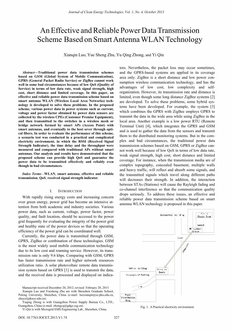
II. DESCRIPTION OF THE SCENARIO Generally, power data is transmitted from the sensors in
power distribution room to the switches in public change room and to the host server far away eventually. However, in some scenario the power distribution room and public change room are located in bad circumstances, such as the underground parking, the basement of the housing estate and the concealed tunnel, in which GPRS cannot coverage. As an example, a practical electricity environment is shown in Fig. 1.
From the Fig.1, we can see that a power distribution room is located in the underground parking of an office building next to which there is a security booth, and a public change room as well as a management center is located in a residen-tial building. The distance between the two buildings is about 100 meters away and there is a road, so the power data can be transmitted neither by electric wire nor by ZigBee. Furthermore, there is no GPRS coverage. Using WLAN technology may be a solution. However, the trans-formers in these rooms, the trees between the two buildings and the cars or buses on the road may affect the transmis-sion effectiveness of the wireless signals, so it will be a hard way to transmit the power data from the power distribution room to the public change room stably and reliably. Aiming at this scenario, we developed an effective and reliable pow-er data transmission scheme based on smart antenna WLAN technology so that the power data can be transmitted stably and reliably with high QoS.
III. THE SMART ANTENNA WLAN TECHNOLOGY Smart Antenna WLAN technology uses an antenna array
and digital signal processor to produce space directional beam, and change the direction of AP’s emission signals automatically and adaptively according to the STAs and the WLAN environment so that the main lobe of the desired signal in the STA is enhanced, while the side lobes, which are the interference signals, are weakened [5], [6]. Based on the following advantages of smart antenna WLAN technol-ogy, our motivation is to setup a smart antenna WLAN scheme which has the features of wide coverage, high sys-tem capacity, low interference, and low power consumption for the transmission of power data.
A. Service Oriented In a smart antenna WLAN system the APs can adaptively
transmit variety of antenna beams with different directions, angles, and gains, and detect the existence and accurate po-sition of the STAs automatically. As soon as the AP finds an active STA wants, the antenna in AP will adjust its trans-mission direction to the STA adaptively, so that the signal strength received in the STA is enhanced.
B. Green Environment During the transmission, the AP can point to the active
STA directly, and the energy is concentrated on the STA. In other directions, the transmitting power is low so that its influence of EMI (Electromagnetic Interference) to other equipment or human body is reduced. Therefore, the AP with smart antenna can extend its coverage area without increasing its transmitting power, and reduce the EMI caused. Also the number of APs needed totally is decreased. Smart antenna WLAN scheme is a good solution with low cost and power consumption.
C. Anti-Interference The AP with smart antenna has strong ability of anti-
interference. It can effectively suppress variety of interfer-ences such as Rayleigh fading, co-channel interference and multiple access interference. In the complex electricity envi-ronment mentioned above, there are transformers in the power rooms, trees and buses on the road which affect the transmission efficiency of the wireless, smart antenna WLAN scheme can provide high transmission quality and reliability.
D. High Spectral Efficiency Smart antenna WLAN technology takes advantage of
SDMA (Space Division Multiple Address) and MIMO (Multiple Input Multiple Output) to set up a smart antenna WLAN system in which the STAs can share the available resources such as time, frequency, and codes. By using the spatial multiplexing gain, multiple data can be transmitted simultaneously. Furthermore, as the antenna beam gets nar-row, the co-channel interference is reduced. Therefore, with smart antenna WLAN technology, more data can be trans-mitted simultaneously hence the spectral efficiency is high.
E. Mobile Positioning In a smart antenna WLAN system, the APs with smart an-
tenna can obtain the space characteristic matrix of the re-ceived signal, and then get the direction of arrival and power valuation of the signals. Therefore, the accurate position of the STA can be easily found out.
MF7211-XX10Outdoor CPE
ZF7762Outdoor AP
Mesh
ZF7762Outdoor AP
ZD3000Wi-Fi Controller
Host server
ZF7962Indoor AP
MF7211-XX10Outdoor CPE
MF7211-XX00indoor CPE
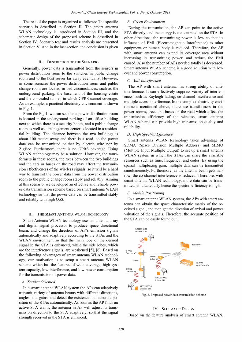
Fig. 2. Proposed power data transmission scheme
IV. SCHEMATIC DESIGN Based on the feature analysis of smart antenna WLAN,
328
Journal of Clean Energy Technologies, Vol. 1, No. 4, October 2013

the power data transmission system is designed by using with smart antenna WLAN technology and shown in Fig. 2, in which several wireless CPEs, APs with smart antenna and a Wi-Fi controller are included.
In this scheme, the wireless CPEs are directly connected to the power data sensors which collect various power data in power systems, such as current, voltage and power factor, and communicate with the smart AP which contains 19 ver-tical and horizontal polarization directional antenna units. The smart AP working over 802.11n can operate in either a 20MHz or a 40MHz bandwidth and be configured as a MIMO system by the multiple antenna architecture, so that the throughput is enhanced [7]. The transmission rate of the smart APs is up to 300Mbps and it supports two kinds of frequency bandwidth: 2.4 GHz and 5 GHz. These smart APs can form a wireless mesh network including several smart APs and bridges, according to the practical conditions and demands. As soon as the data are received by the CPEs, it will be passed them to the smart APs and choose the best path to be transmitted automatically until it arrives at the last AP connected with the switch. And eventually, the data is transmitted from the switch to the host sever through optical fibers. In our design, the Wi-Fi controller connected with the switches is used to manage the smart APs.
V. SCENARIO TEST AND RESULTS ANALYSIS Our experiment has been carried out in the practical sce-
nario as shown in Fig. 1. The wireless CPE is set on the roof of the security booth and the smart AP on a pole before the management center. The wireless CPE is connected with the power data sensors in power distribution room by etheric line. The specific connection mode of the devices is shown in Fig. 3.
Fig. 3. The specific connection mode of the devices
1 2 3 4 5 6 7 8 9 10-70
-60
-50
-40
-30
-20
-10
0
N
Am
plitu
de(d
Bm
)
smart APcommon AP
Fig. 4. RSSI
The RSSI, time delay, and the throughput of the smart AP
and the common AP are measured, respectively to evaluate the performance of this scheme. The testing tools used are Zap and inSSIDer software. Zap is used to test the time de-
lay and the throughput while inSSIDer is employed to test the RSSI. The test results are shown in Fig. 4 to Fig. 9 as follows:
The RSSI result given in Fig. 4 shows that the RSSI of smart AP is better than common AP in any case because the smart AP with smart antenna has stronger anti-interference ability.
The signal strength of the smart AP and the common AP without interference is displayed in Fig. 5 and Fig. 6, re-spectively. We can see that in the circumstance without in-terferences, the signal strength of the smart AP is a little slower than the common AP, but in the circumstance with interferences, the effects of these two APs are much differ-ent. From the Fig. 7, we also know that the rangeability of the smart AP is much smaller than the common AP. In this figure, ‘power-1’ is the SSID (Service Set Identifier) of smart AP while ‘power’ is that of common AP. For the common AP, when a car or a bus is going through the road, the signals are kept off and the SSID ‘power has a sharp drop as indicated in Fig.7. In general, if the signal strength drops down to -70 dBm, it is a serious signal attenuation condition, the wireless CPE may disconnect with the com-mon AP, and the worst, the transmission of the data may be interrupted suddenly. Nevertheless, these situations will not happen when the smart AP is used.
Fig. 5. Signal strength change curve without interference for smart AP
Fig. 6. Signal strength change curve without interference for common AP
Fig. 7 Signal strength change curve with interference for the two Aps
50 100 150 200 250 300 350 400 450 5000
50
100
150
200
250
300
350
N
Tim
e de
lay(
ms)
smart APcommon AP
Fig. 8. Graph of the Time delay
329
Journal of Clean Energy Technologies, Vol. 1, No. 4, October 2013

Fig. 8 shows the time delay and Fig. 9 displays the throughput of the smart AP and the common AP, respective-ly. From these two figures, we can see that the smart AP has better performance than the common AP, that is, its time delay is lower and the throughput is more stable than com-mon AP.
0 50 100 150 200 250 300 350 400 450 5000
2
4
6
8
10
12
14
16
18
20
N
Thro
ughp
ut(M
bps)
smart APcommon AP
Fig. 9. Graph of the Throughput
VI. CONCLUSION In this paper, an effective and reliable power data trans-
mission scheme based on smart antenna WLAN technology is developed. Our analysis and test results in a practical and complicated electricity environment have demonstrated that with the smart antenna WLAN technology the proposed scheme can provide high QoS and guarantee the power data to be transmitted effectively and reliably even though in bad circumstances.
ACKNOWLEDGMENT The authors thank Feng Zhang for his technical support in
the scenario test, and Guangzhou South Power Group Tech-nology Development co., LTD., the provider of the power data sensors for the help in the scenario test. Also thank Liming Ma, Huabing Zhang and Hongyuan Chen for their help in the design and research. The work described in this paper was supported by the 973 Program, 2012CB315904, China, and the Research Program of Shenzhen, China.
REFERENCES [1] A. Hao, X. Zhang, X. Fei, and X. Lian, “Design of solar photovoltaic
remote data transmission system based on GPRS,” in Proc. 2010 In-ternational Conf. Measuring Technology and Mechatronics Automa-tion, 2010, pp. 1038-1042.
[2] Y. Wang, K. Chen, C. Xue, and H. Li, “Design and implementation for ZigBee long-distance wireless data transmission system,” in Proc. 2011 10th International Conf. Electronic Measurement and Instru-ments, 2011, pp. 61-64.
[3] X. Shi, L. Shen, and M. Ling, “A wireless network based on the com-bination of ZigBee and GPRS,” in Proc. IEEE International Conf. Networking, Sensing and Control, 2008, pp. 267-270.
[4] C. Li, T. Ding, K. Chen, and Q. Chen, “Improved design of remote wireless transmission terminal using GPRS/GSM integrated network,” in Proc. International Workshop Intelligent Systems and Applications, 2009, pp. 1-4.
[5] S. R. Inamdar, R. M. Yadahalli, and B. S. Babu “Smart antenna sys-tem using cross layer design in wireless ad hoc networks: trends and challenges,” World Journal of Science and Technology, vol. 2, no. 5, 2012, pp. 74-79.
[6] I. Nicolaescu and D. Stoica “Smart antennas for wireless communica-tions systems,” in Proc. ICECom, 2010 Conference Proceedings, 2010, pp. 1-4.
[7] S. Kandeepan, G. Baldini, and R. Piesiewicz “Experimentally detect-ing IEEE 802.11n Wi-Fi based on cyclostationarity features for ultra-wide band cognitive radios,” in Proc. 2009 IEEE 20th International Symposium. Personal, Indoor and Mobile Radio Communications, 2009, pp. 2315-2319.
Xianqin Luo received her Bachelor's degree in Elec-tronic science and technology in central China Nor-mal University in 2010. She has been studying for a Master’s degree majored in Technology of Computer Application in Peking University since 2010. Her current interests include wireless communications and wireless sensor networks.
Yuesheng Zhu received his Bachelor's degree in Radio Engineering, Master’s degree in Circuits and Systems and Ph.D. degree in Electronics Engineering in 1982, 1989 and 1996, respectively. Professor Zhu has been working with Communication and Security Lab, Shenzhen Graduate School, Peking University, China since 2005. He is a senior member of IEEE, Fellow of China Institute of Electronics and a senior member of China Institute of
Communications. His current interests include digital signal processing in communications, wireless communications, cryptography and internet security, and multimedia technology.
Yuqing Zhong was born in Nanchang, Jiangxi. He is a senior engineer with Guangzhou power supply bureau co., LTD. His current interests include electric power communication planning, operation, and technical management.
Yi Qin received his Bachelor's degree in Electrical Engineering, Master’s degree in Management Information System and Ph.D. degree in Electrical Engineering in 1994, 2000 and 2004, respectively. Dr. Qin has been working with Microgrid EMS Engineering Lab., Shenzhen, China since 2011. His current interests include DC Microgrid System, wireless sensor network, and Signal processing in communications.
330
Journal of Clean Energy Technologies, Vol. 1, No. 4, October 2013