an ekv model user’s perspective: for low-power circuits and beyond€¦ · · 2011-12-20an ekv...
TRANSCRIPT

An EKV Model User’s Perspective: For Low-Power Circuits and Beyond
EKV Users’ Meeting/Workshop, EPFL, Lausanne 4-5/11/2004
Patrick Mawet, Principal EngineerMicro Encoder Inc

MICRO ENCODER INC. 2
Agenda
• MEI introduction• Why use the EKV model?• Our experience using the model in a
low-power circuit• Where to get the models? • Beyond low-power circuits: using EKV
model for analog IC design in general• Concluding comments

MICRO ENCODER INC. 3
• Founded 1986
• Subsidiary of Mitutoyo Japan
• Independent Washington State Corporation
• Located in Kirkland, WA, USA
• 63 employees
• Research and development of technologies for dimensional metrology and other applications– Initial focus was capacitive encoder technology (Digimatic)
– QuickVision vision measurement software & research started 1994
– Now continuing QV work and other advanced sensor research

MICRO ENCODER INC. 4
MEI’s Work…
SOURCE
GRATINGIMAGE
Grating,pitch d
Plane wave input
Diffractedbeam
λd
λ
S15
S1
RST1
VREF1
R1
500C4 1PF
+
+-
-
SDN U3
PREAMP
PR+
IN+
A+S2
RST1
C21PF
C81PF
RST1
S13
S5
RST1
IN-
C71PF
C6 1.7PF
SH-
VREF2
S11
RST2
B+
PR-C3 1PF
V69.21mV
SMP
S3
VREF2
S14
R2
500
INT
C5 1.7PF
RST1
S4
A- B-
SH+
S12
OUT+
+
+-
-
U4
OPAMPIB = 0.25
OFFSET = 10mV
S10
RST1
RST2
C11PF
SDN
OUT-
S6
#ifndef QVAPIif ( m_pPickListManager ){
QVRegistry& rRegistry = Singleton<QVRegistry>::Instance();
int maxItems = m_pPickListManager->GetItemCount();;for ( int i = 1; i <= maxItems; i++ ){
PICK_LIST_ITEM item;m_pPickListManager->GetNthItem( i, &item, FALSE ); // i IS ONE-BASED
CString czSubKey = VPSECTION_PROGRAMCONTROL;czSubKey += _T("\\PickList");TCHAR Str[5] = _T("");_itot(i, Str, 10);czSubKey += Str;
rRegistry.WriteSTRING( czSubKey, _T("FileName"), item.m_szPath);rRegistry.WriteINT( czSubKey, _T("Start"), item.dwStart);rRegistry.WriteINT( czSubKey, _T("End"), item.dwEnd);
}
delete m_pPickListManager;m_pPickListManager = NULL;
}#endif}
( ) ( )
( ) ( ) ( ) ( )[ ] ( )
( ) ( ) ( )[ ] ( )[ ] ( )[ ]
( )∑∑
∑
∑
∑
−
=
−
=
−
=
−
=
−
=
−−+=
−+−−+−−+−+=
−+−+−+−+=
−−=′
1
0
1
0
1
0
1
0
1
0
22cos11
sin222cos122cos122sin11
sinsinsincos12
sin2
M
mm
M
mi
M
mmimimmi
m
M
mimimmi
M
mmmii
iMM
iiiidrM
iiiidrM
iSM
NSI
αϕδδε
αϕµαϕεαϕδαϕ
αϕµαϕεαϕδαϕ
αϕδϕ( )
dnldnl
dldxexT
dc
l
l
dxni
n //sin)(1 2/
2/
2
πππ
== ∫−
−
0 64 128 192 256 320 384 448 512 576 640
sample 0Reset
sample 0Reset
sample 1
sample 1hold
704 736
hold
hold
1760 uS
Tranmit Cap A
Tranmit Cap B/C
Preamps 0-2
Integrators 0-2
Integrators 3-5
ADC
0.4 uS 2418 uA
3.75 uA
3.75 uA
19.5 uA
4.05 nA/sample/sec
Centerline of sample - Scale A and (B or C)
))1(1()/('2
),( ')'2/('
1
4//22 pnnnnip
nn
p
izi
ienpdxTnn
ezxU −++= ∑=
− πλπ

MICRO ENCODER INC. 5
Mitutoyo Products with MEI TechnologyMitutoyo Products with MEI Technology
Coolant Proof
QUICK VISION® QVPAK®
Coming soon
Coming soon
www.mitutoyo.com
MICRO ENCODER INC. 6
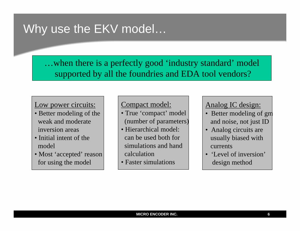
Why use the EKV model…
…when there is a perfectly good ‘industry standard’ modelsupported by all the foundries and EDA tool vendors?
Low power circuits:• Better modeling of theweak and moderateinversion areas
• Initial intent of the model
• Most ‘accepted’ reasonfor using the model
Compact model:• True ‘compact’ model(number of parameters)
• Hierarchical model:can be used both for simulations and hand calculation
• Faster simulations
Analog IC design:• Better modeling of gm
and noise, not just ID• Analog circuits are
usually biased withcurrents
• ‘Level of inversion’design method

MICRO ENCODER INC. 7
My experience with the EKV modelAttended E. Vittoz lectures on low-power analog design.
“Cool stuff! – How in the world can I use this?”
Low-power IC project.Decide to use EKV
Initially struggled to‘estimate’ EKV model
Extracted model fromvendor-supplied samples
Convinced vendor tosupport the model
Successful project
‘Converted’ to the level of inversion design methodNow what?
Later, attended C. Enz lecture on the EKV model. “OK, I’m sold! – Now, I want to use this”
MICRO ENCODER INC. 8
Getting started with the EKV model: a low-power (uAmps) analog circuit
• Many circuits used transistors in weak and moderate inversion – need for an accurate model through all modes of operations.
• At first, the foundry supplied us with transistor arrays to extract the model– We rented a HP4155B, and proceeded with doing our own
extraction– We got reasonably good results, but not without challenges
• I presented the EKV model and its advantages for low-power design to the vendor.
• Eventually, the foundry’s modeling expert ‘bought’ and studied the model, and the foundry supplied the models for this project (they have better hardware and software tools to do this).
• This was a successful story about promoting the model acceptance.
MICRO ENCODER INC. 9
EKV 2.6 extraction challenges
• I am a circuit designer, not a modeling expert! (However, MOS modeling is definitely an interest of mine).
• The model is simple (few parameters), but getting the best possible fit for all sizes/conditions is not so easy.
• Limitation in hardware/software. – Hardware: very low current measurements required – HP4155B
worked well.– Software: used Pspice + Matlab + Excel – no real extraction
system.• Some of the specific difficulties I encountered:
– Short-channel NMOS: difficulty in matching the drain current both at low and high gate voltages. (due to absence of 2nd order mobility reduction in EKV 2.6).
– PMOS: difficulties in matching the drain current in both in linear and saturation regions.
• Solution: optimize the model for the project conditions.

MICRO ENCODER INC. 10
Where to get the models?:1. - ‘Extract’ from the BSIM model (‘OK’)
0
5
10
15
20
25
30
1.E-11 1.E-09 1.E-07 1.E-05 1.E-03
Id, A
gm/Id
BSIMEKV
0.E+00
1.E-03
2.E-03
3.E-03
4.E-03
5.E-03
6.E-03
0 1 2 3 4 5
VD, V
ID, A
• Often, it is the only available option.
• However, we are extracting from a model that is not ‘perfect’.
• Upcoming tools?
Possible compromise:• Get typical transistors curves
from the foundry (if willing).• Replay the model against the
curves for fine tuning.• Good solution for a better
model with minimal involvement from the foundry.
• ‘Reality check’

MICRO ENCODER INC. 11
Where to get the models?:2. - Extract from transistor samples (better)
Big questions/concerns:• Typically, will work from a
limited set of samples provided by the vendor.
• Are the samples representative of the ‘typical’ process?
• Requires some hardware (low current measurements).
• ‘Good’ extraction is not so easy.
Use a qualified extraction service• Better solution, but…• May be expensive.• The concerns about the
transistor samples remain valid. 0
1
2
3
4
5
6
0 1 2 3 4 5
Drain voltage, V
Dria
n cu
rren
t, m
A

MICRO ENCODER INC. 12
Where to get the models?:3. – Have the foundry supply the model (best)
• Best solution - the foundry has access to:– Knowledge of the process.– A lot of process data.– Extraction hardware/software.
• But… a lot of resistance– Difficult to convince the foundry to have to support another
model.– Not ‘industry standard’.– Traditionally, the market has been dominated by digital IC’s.– However… mixed-signal SOC’s are becoming more
relevant! – SOC is the new ‘buzz word’.• Analog/mixed-signal foundries.
– Should consider supporting the model for analog designers.– Low-power processes are prime candidates.

MICRO ENCODER INC. 13
Beyond low-power circuits: Analog circuit design
• The EKV model is also very good for analog circuits in general– Several features useful for the analog IC designer: matching
parameters, estimation of drain/source parasitics…– The model can be easily used for hand calculations and
optimization (see next slide).– The gm/ID equation is based on currents – most analog circuits
are biased with currents – So, why base our calculations on a voltage (Vdsat)?
– The model was designed by analog IC designers for analog IC designers.
– The model is valid for all modes of operation (weak – moderate –strong inversion).
• The main roadblocks are model acceptance and availability. The ‘industry standard’ BSIM model dominates the industry.
• Need to educate designers, foundries and EDA vendors.

MICRO ENCODER INC. 14
Example of circuit optimization using the EKV -equations: low noise (not low power) op-amp:
mn
ff
fD
m
S
Df
gKTV
ii
n
iUTnIg
IIi
4
32
21
11
14121
2 ⋅=
⎟⎠⎞
⎜⎝⎛ ⋅+⋅
+⋅=
+⋅+⋅
⋅=
=
γ
γ
0
1000
2000
3000
4000
5000
6000
0.1 1 10
if(M1/2), if(M3/4)=10
nV2/
Hz/u
A
Vneq2*ID(M1/2)
Vneq2*ID(M3/4)
Vneq2*ID(Total)

MICRO ENCODER INC. 15
EKV model -> Level of inversion design method for transistor sizing
Transistor size W, L
Specific current Is
Bias current ID
Level of Inversion If=ID/Is
Mode of operationAC characteristics (gm, C’s)Dc gain, matchingNoise (thermal & flicker)…
0.1
1
10
100
0.001 0.01 0.1 1 10 100 1000
If
gm/Id

MICRO ENCODER INC. 16
The Level of Inversion Methodology
• Uses continuous linear equations to calculate gm and thermal noise from transistor size and bias current, valid for all modesof operation of the transistor.
• I used this method to optimize a low-noise amplifier, in a normal (not battery powered) application. This was very successful. However, the BSIM model was used for simulations. (In the moderate to strong inversion, the BSIM is OK, at least for gm)
• More logical method of sizing transistors from the bias current.• I now use this for all design. It just requires estimating the
specific current for different transistor sizes (L).• The level of inversion design method has now been presented
in papers and seminars (D. Binkley, D. Foty) since then.

MICRO ENCODER INC. 17
Example of ‘computer-aided hand calculations’: My handy transistor calculator!

MICRO ENCODER INC. 18
Concluding comments
• The EKV model (2.6) is now supported by most EDA tools/simulators.
• It is a superior model for low-power analog IC design.• The main issue for the user is ‘where to get the models’ – 3
different solutions.• It is also a better model for analog IC design in general (‘level of
inversion’ method).• Any questions?