an elastic metamaterial beam for broadband vibration ...€¦ · an elastic metamaterial beam for...
TRANSCRIPT
An Elastic Metamaterial Beam for Broadband Vibration
Suppression
R. Zhua, G. K. Hu
b, M. Reynolds
c and G. L. Huang
*,a
aDepartment of Systems Engineering, University of Arkansas at Little Rock, Little Rock, AR 72204, USA
bKey Laboratory of Dynamics and Control of Flight Vehicle, Ministry of Education, School of Aerospace
Engineering, Beijing Institute of Technology, Beijing 100081, China
cCollege of Science, Technology, Engineering and Mathematics, University of Arkansas at Fort Smith, Fort Smith,
AR 72913, USA
ABSTRACT
One of the significant engineering applications of the elastic metamaterial is for the low-frequency vibration
absorption because of the existence of low-frequency bandgaps. However, the forbidden gap from existing elastic
metamaterials is of narrow bandwidth which limits their practical engineering application. In this paper, a chiral-
lattice-based elastic metamaterial beam with multiple resonators is suggested for the broadband vibration
suppression by overlapping their resulting bandgaps. First, a theoretical modeling of the metamaterial beam with
periodically multiple resonators is performed for bending wave propagation. The wave interaction between the
multiple resonators is found to generate new passbands, which is a barrier to form a complete bandgap. To address
this issue, a section distribution of the multiple resonators is suggested to diminish the interaction. Finally, the
chiral-lattice-based metamaterial beam is fabricated and experimental testing of the structure is conducted to
validate the proposed design. This work can serve as a theoretical and experimental foundation of the broadband
vibration suppression by using the metamaterial structure in practical engineering applications.
Keywords: elastic metamaterial beam, vibration suppression, broadband wave
1. INTRODUCTION
Elastic Metamaterials (EMMs) have gained much attention due to their unique microstructure design to achieve the
effective elastic material properties which cannot be observed in nature [1]. The working principle of the EMM is to
use man-made microstructures (resonators) on a scale much less than its working wavelength. As a result, a low-
frequency bandgap can be observed in an EMM with small dimensions, within which the wave energy cannot
propagate and is trapped in the resonator. The unusual low-frequency bandgaps in such a composite were explained
by the locally resonant (LR) mechanism, which can be homogenized as the negative effective mass density of the
composite through equivalent discrete mass-spring systems [2-5].
* [email protected]; phone 1 501 683-7522; fax 1 501 569-8698
Health Monitoring of Structural and Biological Systems 2013, edited by Tribikram Kundu, Proc. of SPIEVol. 8695, 86952J · © 2013 SPIE · CCC code: 0277-786X/13/$18 · doi: 10.1117/12.2012263
Proc. of SPIE Vol. 8695 86952J-1
Downloaded From: http://proceedings.spiedigitallibrary.org/ on 07/31/2015 Terms of Use: http://spiedigitallibrary.org/ss/TermsOfUse.aspx
Because of the existence of low-frequency bandgaps, one of the significant engineering applications of the EMM is
for the low-frequency vibration absorption. Different from the Bragg scattering mechanism in phononic crystals [6,
7], the LR mechanism could be easily tuned through proper microstructure design, and low-frequency vibration
energy could be quickly attenuated within only a small amount of the periodic microstructures [8]. Therefore, no
gigantic meta-structure is needed to shield structural subject from the low-frequency vibration or wave loading.
Engineering structures such as rods, beams and plates with desired LR microstructure design can be implemented
for vibration suppression. Xiao et al. [9] investigated wave propagation and vibration transmission in elastic rods
containing periodically attached multi-degree-of-freedom spring–mass resonators. Yu et al. [10] studied the flexural
wave propagation in a beam with many spring-mass subsystems as bending wave absorbers. Chen et al. [11]
analytically and experimentally studied the dynamic behavior of a sandwich beam with internal mass-spring
resonators. However, the forbidden gap from the current metamaterial design is often of narrow bandwidth, which
significantly limits its potential engineering application. To address this problem, band gaps in a multi-resonator
acoustic metamaterial were investigated [12]. It was found that the band gaps can be tuned by varying the physical
parameters of the internal resonators. Pai [13] theoretically demonstrated that the longitudinal broadband wave
absorption can be achieved in a bar structure with distributed absorbers related to different frequency stop bands in
different sections. However, these microstructure designs, mainly as mass-spring systems, are conceptual and far
from reality, and they are not practical to be manufactured as load-bearing engineering structures. A chiral-lattice-
based metacomposite beam was recently proposed by integrating two-dimensional periodic chiral lattice with EMM
inclusions for low-frequency wave applications [14]. The vibration absorption function was demonstrated through
the numerical analysis of the band diagram. The major advantage of the proposed beam is that the significant wave
attenuation is localized within the structure, which requires no additional components. Additionally, the chiral
structure beam can still be made from stiff and high strength materials so as not to sacrifice load-bearing capacity.
To design the chiral-lattice-based metamaterial for vibration absorption in a broad frequency regime, the
metamaterial beam with multiple inner resonators should be properly designed.
In this paper, a chiral-lattice-based EMM beam with multiple resonators is numerically and experimentally studied
for the broadband vibration suppression by overlapping their resulting bandgaps. First, based on the transfer matrix
method, a theoretical modeling of a metamaterial beam with multiple resonators is performed for bending wave
propagation. The wave interaction between the multiple inner resonators is observed, which can result in undesired
new wave passbands for a complete bandgap. A distributed section design of multiple resonators is thus suggested to
diminish the resonator interaction to achieve broadband vibration suppression. Finally, the chiral-lattice-based
metamaterial beam is fabricated and experimental vibration testing of the structure is conducted to validate the
proposed design.
2. BENDING VIBRATION IN A BEAM WITH MULTIPLE RESONATORS
The band structure of bending vibration in a beam with a single LR structure has been investigated based on the
transfer matrix theory [15]. In the study, we extend this method to determine the band structure of bending vibration
of a beam with multiple resonators. Attention will be paid on the new passing band generated because of the
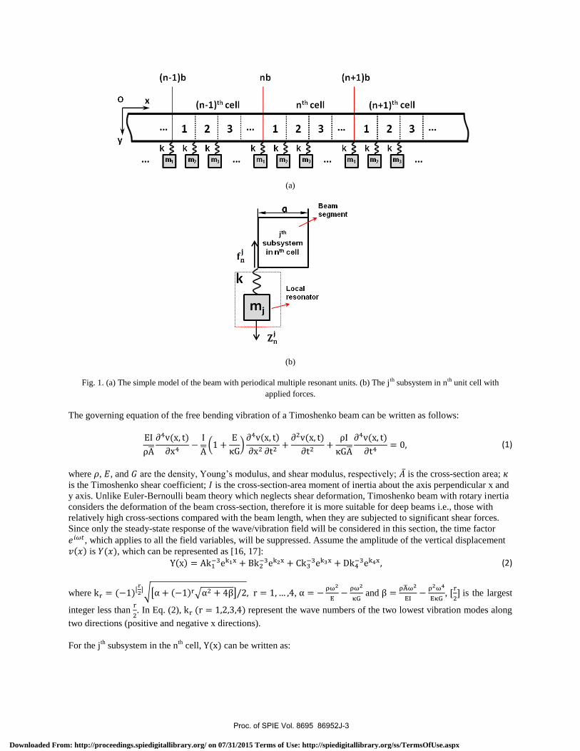
interaction among multiple resonators. To clearly illustrate the problem, a simple model of a beam with periodical
multiple LR units is studied as shown in Fig. 1 (a). Each unit consists of subsystems in which mass-spring
resonators are attached to the beam at a spacing of along x direction. Each subsystem has two parts, beam segment
and resonator, which consists of an elastic spring and a mass , as shown in Fig. 1(b). The lattice
constant of the periodic system is denoted as .
Proc. of SPIE Vol. 8695 86952J-2
Downloaded From: http://proceedings.spiedigitallibrary.org/ on 07/31/2015 Terms of Use: http://spiedigitallibrary.org/ss/TermsOfUse.aspx
jth
subsystemin nth cell
mi
(a)
(b)
Fig. 1. (a) The simple model of the beam with periodical multiple resonant units. (b) The jth subsystem in nth unit cell with
applied forces.
The governing equation of the free bending vibration of a Timoshenko beam can be written as follows:
(1)
where , , and are the density, Young’s modulus, and shear modulus, respectively; is the cross-section area;
is the Timoshenko shear coefficient; is the cross-section-area moment of inertia about the axis perpendicular x and
y axis. Unlike Euler-Bernoulli beam theory which neglects shear deformation, Timoshenko beam with rotary inertia
considers the deformation of the beam cross-section, therefore it is more suitable for deep beams i.e., those with
relatively high cross-sections compared with the beam length, when they are subjected to significant shear forces.
Since only the steady-state response of the wave/vibration field will be considered in this section, the time factor
, which applies to all the field variables, will be suppressed. Assume the amplitude of the vertical displacement
is , which can be represented as [16, 17]:
(2)
where
,
and
,
is the largest
integer less than
. In Eq. (2), represent the wave numbers of the two lowest vibration modes along
two directions (positive and negative x directions).
For the jth
subsystem in the nth
cell, can be written as:
Proc. of SPIE Vol. 8695 86952J-3
Downloaded From: http://proceedings.spiedigitallibrary.org/ on 07/31/2015 Terms of Use: http://spiedigitallibrary.org/ss/TermsOfUse.aspx
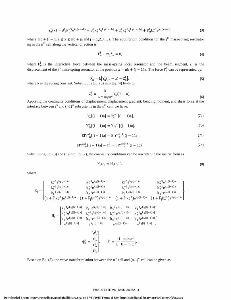
(3)
where and . The equilibrium condition for the jth
mass-spring resonator
mj in the nth
cell along the vertical direction is:
(4)
where
is the interactive force between the mass-spring local resonator and the beam segment, is the
displacement of the jth
mass-spring resonator at the position . The force can be represented by:
(5)
where k is the spring constant. Substituting Eq. (5) into Eq. (4) leads to
(6)
Applying the continuity conditions of displacement, displacement gradient, bending moment, and shear force at the
interface between jth
and (j-1)th subsystems in the n
th cell, we have:
(7a)
(7b)
(7c)
(7d)
Substituting Eq. (3) and (6) into Eq. (7), the continuity conditions can be rewritten in the matrix form as
(8)
where,
Based on Eq. (8), the wave transfer relation between the nth
cell and (n-1)th
cell can be given as
Proc. of SPIE Vol. 8695 86952J-4
Downloaded From: http://proceedings.spiedigitallibrary.org/ on 07/31/2015 Terms of Use: http://spiedigitallibrary.org/ss/TermsOfUse.aspx
(9)
where
is the transfer matrix between the two cells [18]. It is noticed that the transfer matrix
approach based on the coefficient of can obtain the same result by using the transfer matrix approach based on
the global solution, such as: displacement, displacement gradient, bending moment and shear force.
For an infinite periodic locally resonant beam, Bloch theorem can be applied
(10)
where is the wave vector in the direction. Inserting Eq. (9) into Eq. (10) yields the eigen-value problem:
(11)
For clear demonstration, a numerical study is conducted on the periodic metamaterial beam consisting of two locally
resonant subsystems with masses and , respectively. The material and geometrical parameters used in the
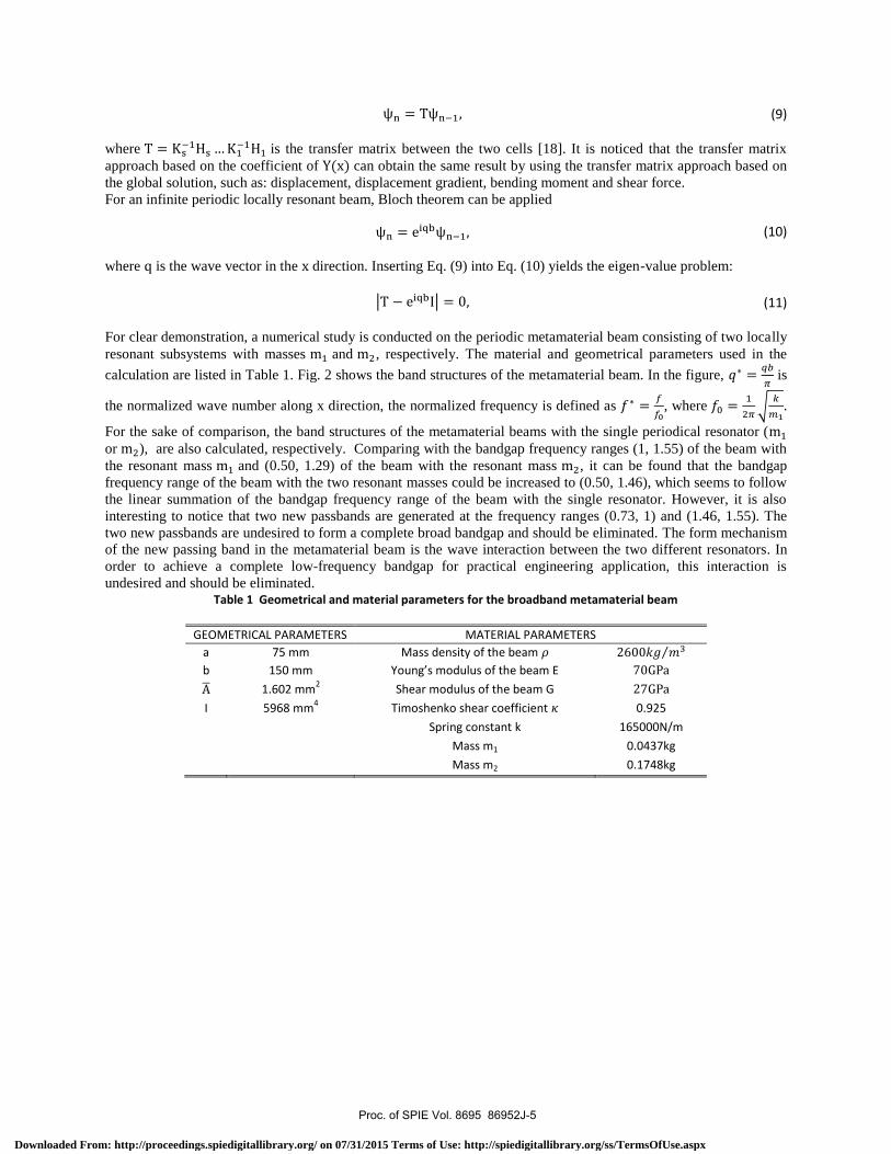
calculation are listed in Table 1. Fig. 2 shows the band structures of the metamaterial beam. In the figure,
is
the normalized wave number along x direction, the normalized frequency is defined as
, where
.
For the sake of comparison, the band structures of the metamaterial beams with the single periodical resonator (
or ), are also calculated, respectively. Comparing with the bandgap frequency ranges (1, 1.55) of the beam with
the resonant mass and (0.50, 1.29) of the beam with the resonant mass , it can be found that the bandgap
frequency range of the beam with the two resonant masses could be increased to (0.50, 1.46), which seems to follow
the linear summation of the bandgap frequency range of the beam with the single resonator. However, it is also
interesting to notice that two new passbands are generated at the frequency ranges (0.73, 1) and (1.46, 1.55). The
two new passbands are undesired to form a complete broad bandgap and should be eliminated. The form mechanism
of the new passing band in the metamaterial beam is the wave interaction between the two different resonators. In
order to achieve a complete low-frequency bandgap for practical engineering application, this interaction is
undesired and should be eliminated. Table 1 Geometrical and material parameters for the broadband metamaterial beam
GEOMETRICAL PARAMETERS MATERIAL PARAMETERS
a 75 mm Mass density of the beam
b 150 mm Young’s modulus of the beam E
1.602 mm2
Shear modulus of the beam G
I 5968 mm4
Timoshenko shear coefficient 0.925
Spring constant k 165000N/m
Mass m1 0.0437kg
Mass m2 0.1748kg
Proc. of SPIE Vol. 8695 86952J-5
Downloaded From: http://proceedings.spiedigitallibrary.org/ on 07/31/2015 Terms of Use: http://spiedigitallibrary.org/ss/TermsOfUse.aspx
-x
2.5with single resonant subsystem (m, )
.
1.0 -
0.5-
with single resonant subsystem (m2)
100 0.5
qn
with two resonant subsystems (m1& m2
.
10 0
(a) (b) (c)
Fig. 2. Band structures of the beams with (a) a single resonator ; (b) a single resonator ; (c) two resonators ( and
).
3. EXPERIMENTAL TESTING OF THE METAMATERIAL BEAM WITH
DISTRIBUTED SECTION DESIGN
In the section, a distributed section design of multiple resonators in the finite EMM beam is proposed to diminish
the wave interaction between different resonators. Furthermore, in order to apply the proposed broadband design in
the realistic structures, a chiral-lattice-based metamaterial beam integrated with different section-distributed
resonators is fabricated. Chiral lattice is selected due to its excellent stiffness-to-weight ratio and potential of
massive production. The resonators are implanted in the node circles of the chiral lattice therefore the load bearing
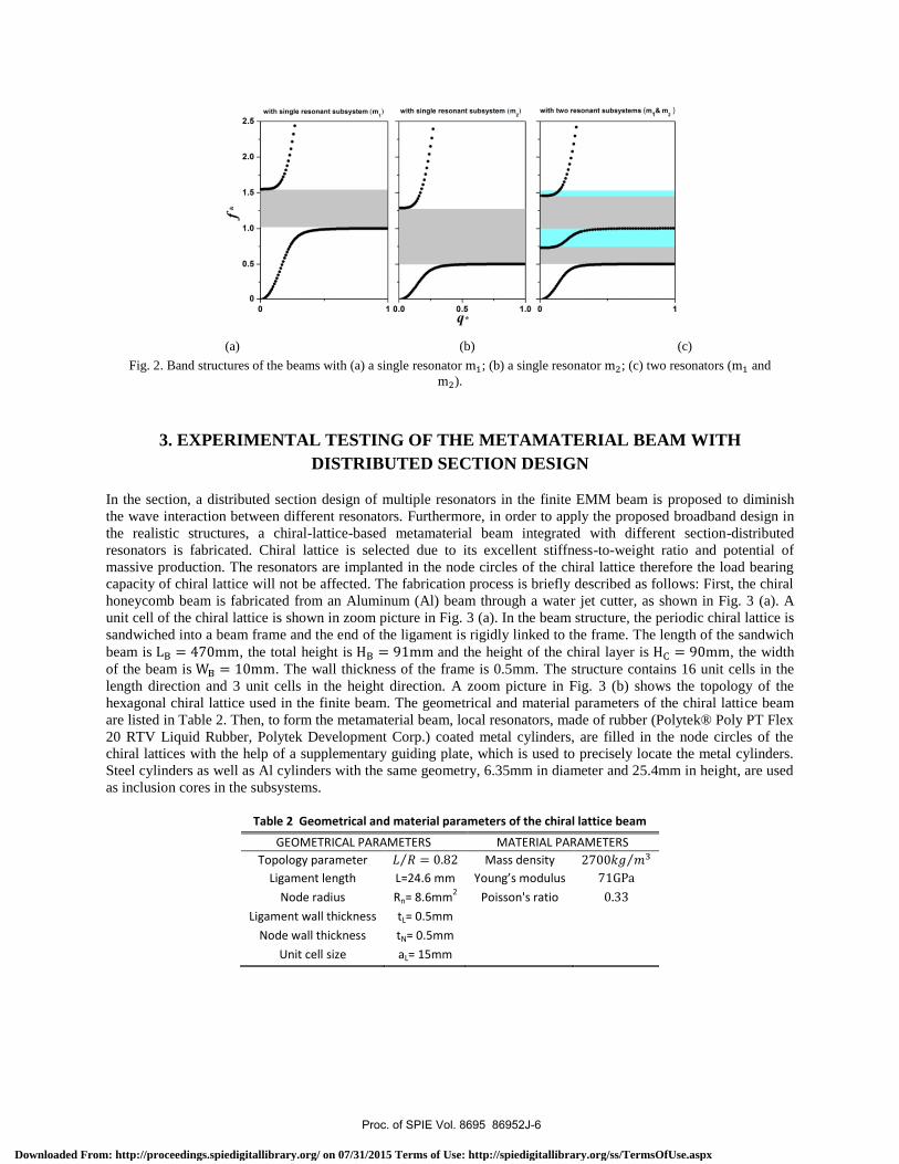
capacity of chiral lattice will not be affected. The fabrication process is briefly described as follows: First, the chiral
honeycomb beam is fabricated from an Aluminum (Al) beam through a water jet cutter, as shown in Fig. 3 (a). A
unit cell of the chiral lattice is shown in zoom picture in Fig. 3 (a). In the beam structure, the periodic chiral lattice is
sandwiched into a beam frame and the end of the ligament is rigidly linked to the frame. The length of the sandwich
beam is , the total height is and the height of the chiral layer is , the width
of the beam is . The wall thickness of the frame is 0.5mm. The structure contains 16 unit cells in the
length direction and 3 unit cells in the height direction. A zoom picture in Fig. 3 (b) shows the topology of the
hexagonal chiral lattice used in the finite beam. The geometrical and material parameters of the chiral lattice beam
are listed in Table 2. Then, to form the metamaterial beam, local resonators, made of rubber (Polytek® Poly PT Flex
20 RTV Liquid Rubber, Polytek Development Corp.) coated metal cylinders, are filled in the node circles of the
chiral lattices with the help of a supplementary guiding plate, which is used to precisely locate the metal cylinders.
Steel cylinders as well as Al cylinders with the same geometry, 6.35mm in diameter and 25.4mm in height, are used
as inclusion cores in the subsystems.
Table 2 Geometrical and material parameters of the chiral lattice beam
GEOMETRICAL PARAMETERS MATERIAL PARAMETERS
Topology parameter Mass density
Ligament length L=24.6 mm Young’s modulus
Node radius Rn= 8.6mm2
Poisson's ratio
Ligament wall thickness tL= 0.5mm
Node wall thickness tN= 0.5mm
Unit cell size aL= 15mm
Proc. of SPIE Vol. 8695 86952J-6
Downloaded From: http://proceedings.spiedigitallibrary.org/ on 07/31/2015 Terms of Use: http://spiedigitallibrary.org/ss/TermsOfUse.aspx
Ak h .`.`...ir,.....A.,,AwAsv.-, IO
I. ,11,.`_1r.r.. trao1/4144/0A,.r. .rs ..
irf
Accelerometer
ForceTransducer
Dynamic Signal Analyzer
(a)
(b)
Fig. 3. (a) Chiral lattice beam and the unit cell of the chiral lattice in zoom picture. (b) The topology of the hexagonal chiral
lattice used in the finite beam.
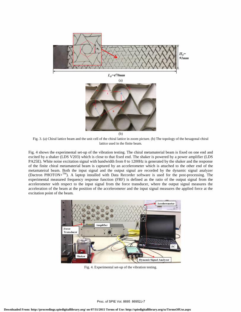
Fig. 4 shows the experimental set-up of the vibration testing. The chiral metamaterial beam is fixed on one end and
excited by a shaker (LDS V203) which is close to that fixed end. The shaker is powered by a power amplifier (LDS
PA25E). White noise excitation signal with bandwidth from 0 to 1200Hz is generated by the shaker and the response
of the finite chiral metamaterial beam is captured by an accelerometer which is attached to the other end of the
metamateiral beam. Both the input signal and the output signal are recorded by the dynamic signal analyzer
(Dactron PHOTON+TM
). A laptop installed with Data Recorder software is used for the post-processing. The
experimental measured frequency response function (FRF) is defined as the ratio of the output signal from the
accelerometer with respect to the input signal from the force transducer, where the output signal measures the
acceleration of the beam at the position of the accelerometer and the input signal measures the applied force at the
excitation point of the beam.
Fig. 4. Experimental set-up of the vibration testing.
Proc. of SPIE Vol. 8695 86952J-7
Downloaded From: http://proceedings.spiedigitallibrary.org/ on 07/31/2015 Terms of Use: http://spiedigitallibrary.org/ss/TermsOfUse.aspx
20
200 400 600 800 1000 1200
Frequency (Hz)
20
10-
-20 -
-30 -,ay0 200 400 600 800 1000 1200
Frequency (Hz)
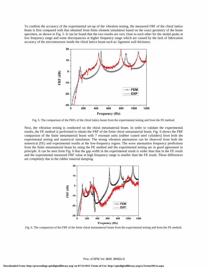
To confirm the accuracy of the experimental set-up of the vibration testing, the measured FRF of the chiral lattice
beam is first compared with that obtained from finite element simulation based on the exact geometry of the beam
specimen, as shown in Fig. 5. It can be found that the two results are very close to each other for the modal peaks at
low frequency range and some discrepancies at higher frequency range which are caused by the lack of fabrication
accuracy of the microstructure inside the chiral lattice beam such as: ligament wall thickness.
Fig. 5. The comparison of the FRFs of the chiral lattice beam from the experimental testing and from the FE method.
Next, the vibration testing is conducted on the chiral metamaterial beam. In order to validate the experimental
results, the FE method is performed to obtain the FRF of the finite chiral metamaterial beam. Fig. 6 shows the FRF
comparison of the finite metamaterial beam with 7 resonant units (rubber coated steel cylinders) from both the
experimental testing and numerical simulation. The strong vibration attenuation can be observed from both the
numerical (FE) and experimental results at the low-frequency region. The wave attenuation frequency predictions
from the finite metamaterial beam by using the FE method and the experimental testing are in good agreement in
principle. It can be seen from Fig. 6 that the gap width in the experimental result is wider than that in the FE result
and the experimental measured FRF value at high frequency range is smaller than the FE result. Those differences
are completely due to the rubber material damping.
Fig. 6. The comparison of the FRF of the finite chiral metamaterial beam from the experimental testing and from the FE method.
Proc. of SPIE Vol. 8695 86952J-8
Downloaded From: http://proceedings.spiedigitallibrary.org/ on 07/31/2015 Terms of Use: http://spiedigitallibrary.org/ss/TermsOfUse.aspx
Local resonators w
ithsteel cylinders
Local resonators
W-ii
Alum
inum cylinders
10
5-
0-
-5 -
-10 -
-15 -
-20 -
-25 -
-300
section distribution designwith only Al resonatorwith only steel resonator
200 400 600
Frequency (Hz)
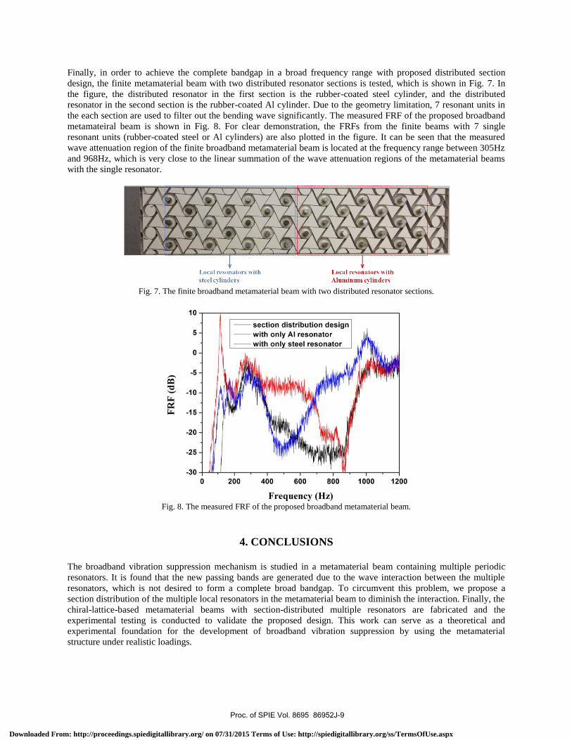
Finally, in order to achieve the complete bandgap in a broad frequency range with proposed distributed section
design, the finite metamaterial beam with two distributed resonator sections is tested, which is shown in Fig. 7. In
the figure, the distributed resonator in the first section is the rubber-coated steel cylinder, and the distributed
resonator in the second section is the rubber-coated Al cylinder. Due to the geometry limitation, 7 resonant units in
the each section are used to filter out the bending wave significantly. The measured FRF of the proposed broadband
metamateiral beam is shown in Fig. 8. For clear demonstration, the FRFs from the finite beams with 7 single
resonant units (rubber-coated steel or Al cylinders) are also plotted in the figure. It can be seen that the measured
wave attenuation region of the finite broadband metamaterial beam is located at the frequency range between 305Hz
and 968Hz, which is very close to the linear summation of the wave attenuation regions of the metamaterial beams
with the single resonator.
Fig. 7. The finite broadband metamaterial beam with two distributed resonator sections.
Fig. 8. The measured FRF of the proposed broadband metamaterial beam.
4. CONCLUSIONS
The broadband vibration suppression mechanism is studied in a metamaterial beam containing multiple periodic
resonators. It is found that the new passing bands are generated due to the wave interaction between the multiple
resonators, which is not desired to form a complete broad bandgap. To circumvent this problem, we propose a
section distribution of the multiple local resonators in the metamaterial beam to diminish the interaction. Finally, the
chiral-lattice-based metamaterial beams with section-distributed multiple resonators are fabricated and the
experimental testing is conducted to validate the proposed design. This work can serve as a theoretical and
experimental foundation for the development of broadband vibration suppression by using the metamaterial
structure under realistic loadings.
Proc. of SPIE Vol. 8695 86952J-9
Downloaded From: http://proceedings.spiedigitallibrary.org/ on 07/31/2015 Terms of Use: http://spiedigitallibrary.org/ss/TermsOfUse.aspx
ACKNOWLEDGEMENTS
This work was supported in part by NASA EPSCoR RID and National Natural Science Foundation of China under
Grants No. 10832002.
REFERENCES
[1] Liu, Z. Y., Zhang, X. X., Mao, Y. W., Zhu, Y. Y., Yang, Z. Y., Chan, C. T., and Sheng, P., “Locally Resonant
Sonic Materials,” Science, 289, 1734–1736 (2000).
[2] Liu, Z. Y., Chan, C. T., and Sheng, P., “Analytic Model of Phononic Crystals with Local Resonances,” Phys.
Rev. B, 71, 014103 (2005).
[3] Milton G. W. and Willis, J. R., “On Modification of Newton’s Second Law and Linear Continuum
Elastodynamics,” Proc. R. Soc. London, Ser. A, 463, 855 (2007).
[4] Zhu, R., Huang, G. L., and Hu, G. K., “Effective Dynamic Properties and Multi-Resonant Design of Acoustic
Metamaterials,” ASME J. Vib. Acoust., 134, 031006 (2012).
[5] Huang, H. H., Sun, C. T., and Huang, G. L., “On the Negative Effective Mass Density in Acoustic
Metamaterials,” Int. J. Eng. Sci., 47, 610 (2009).
[6] Wen, J., Wang, G., Yu, D., Zhao, H., and Liu, Y., “Theoretical and Experimental Investigation of Flexural
Wave Propagation in Straight Beams with Periodic Structures: Application to a Vibration Isolation Structure,”
J. Appl. Phys., 97, 114907 (2005).
[7] Liu, L., and Hussein, M. I., “Wave Motion in Periodic Flexural Beams and Characterization of the Transition
Between Bragg Scattering and Local Resonance,” ASME J. Appl. Mech., 79, 011003 (2012).
[8] Zhu, R., Huang, G. L., Huang, H. H., and Sun, C. T., “Experimental and Numerical Study of Guided Wave
Propagation in a Thin Metamaterial Plate,” Phys. Lett. A, 375, 2863 (2011).
[9] Xiao, Y., Wen, J. H., and Wen, X. S., “Longitudinal Wave Band Gaps in Metamaterial-Based Elastic Rods
Containing Multi-Degree-of-Freedom Resonators,” New J. Phys., 14, 033042 (2012).
[10] Yu, D., Wen, J. H., Zhao, H., Liu, Y. Z., and Wen, X. S., “Flexural Vibration Band Gap in a Periodic Fluid-
Conveying Pipe System Based on the Timoshenko Beam Theory,” ASME J. Vib. Acoust., 133, 014502 (2011).
[11] Chen, J. S., Sharma, B., and Sun, C. T., “Dynamic Behaviour of Sandwich Structure Containing Spring-Mass
Resonators,” Compos. Struct., 93, 2120 (2011).
[12] Huang, G. L., and Sun, C. T., “Band Gaps in a Multiresonator Acoustic Metamaterial,” ASME J. Vib. Acoust.,
132, 031003 (2010).
[13] Pai, P. F., “Metamaterial-based Broadband Elastic Wave Absorber,” J. Intell. Mater. Syst. Struct., 21, 517
(2010).
[14] Liu, X. N., Hu, G. K., Huang, G. L., and Sun, C. T., “Wave Propagation Characterization and Design of Two-
Dimensional Elastic Chiral Metacomposite,” J. Sound Vib., 330, 2536 (2011).
[15] Yu, D., Liu, Y., Wang, G., Zhao, H., and Qiu, J., “Flexural Vibration Band Gaps in Timoshenko Beams with
Locally Resonant Structures,” J. Appl. Phys., 100, 124901 (2006).
[16] Díaz-de-Anda, A., Pimentel, A., Flores, J., Morales, A., Gutiérrez, L., and Méndez-Sánchez, R. A., “Locally
Periodic Timoshenko Rod: Experiment and Theory,” J. Acoust. Soc. Am., 117, 2814 (2005).
[17] Méndez-Sánchez, R. A., Morales, A., and Flores, J., “Experimental Check on the Accuracy of Timoshenko's
Beam Theory,” J. Sound Vib., 279, 508–512 (2005).
[18] Romeo, F., and Luongo, A., “Invariant Representation of Propagation Properties for Bi-coupled Periodic
Structures” J. Sound Vib., 257, 5, 869-886 (2002).
Proc. of SPIE Vol. 8695 86952J-10
Downloaded From: http://proceedings.spiedigitallibrary.org/ on 07/31/2015 Terms of Use: http://spiedigitallibrary.org/ss/TermsOfUse.aspx