an elastic–plastic ice material model for ship-iceberg
TRANSCRIPT
An elastic–plastic ice material model for ship-icebergcollision simulations
Yan Gao a, Zhiqiang Hu a,n,1, Jonas W. Ringsberg b, Jin Wang a
a State Key Laboratory of Ocean Engineering, Shanghai Jiao Tong University, Shanghai, Chinab Department of Shipping and Marine Technology, Chalmers University of Technology, Gothenburg, Sweden
a r t i c l e i n f o
Article history:Received 26 September 2014Accepted 20 April 2015
Keywords:Ship-iceberg collisionIceberg material modelingElastic–plastic materialCutting-plane algorithmNumerical simulation
a b s t r a c t
Ship-iceberg collisions are currently a hot topic of research. The modeling of iceberg material is crucialfor ice mechanics, and the main objective of the present work is to propose an isotropic elastic–perfectlyplastic material model to simulate the mechanical behavior of ice in a ship-iceberg collision scenario forAccidental Limit State conditions. The ‘Tsai-Wu’ yield surface model and a new empirical failure criterionwere used to describe the plastic flow of iceberg material, while a cutting-plane algorithm was adoptedto address the plastic stress–strain relationship. The proposed iceberg material model was incorporatedinto the LS-DYNA finite element code using a user-defined subroutine. Calibration of the proposedmaterial model was conducted through a comparison with an abnormal level ice event pressure-areacurve. The calculated pressure-area curve was comparable to that recommended by the InternationalOrganization for Standardization (ISO) rule. A sensitivity analysis was then conducted, and the proposedice model was found to be more sensitive to the mesh size than to other parameters. Numericalsimulations of iceberg-tanker side and iceberg-ship bow collisions were also analyzed. Moreover, theimpact force and energy dissipation were examined. The results from these simulations showed that theproposed isotropic elastic–perfectly plastic iceberg material model can be employed to simulate icebergbehavior in ship-iceberg collisions under Accidental Limit State conditions.
& 2015 Elsevier Ltd. All rights reserved.
1. Introduction
More voyages across the Arctic are likely to be possible in thefuture due to global warming, however, ships are vulnerable tocollisions with icebergs in this region. As a result, ship-icebergcollisions are currently a hot topic of research. Accurate collisionscenario predictions are necessary for designing ship structures toensure that ships maintain a sufficient safety level. It is crucial toestablish iceberg material models that can be used for realisticrepresentations of iceberg impact loads in ship-iceberg collisionsand structural response predictions.
One approach to predicting ship-iceberg impact loads during theship structure design stage is to use ice class rules, such as the‘Finnish-Swedish Ice Class Rules’ (FSICR, 2008) and InternationalAssociation of Classification Societies (IACS) (IACS, 2011). These rulescan be used to calculate the pressure within a ship-iceberg contactarea based on parameters that are associated with the ice classifica-tion and considered ship structure. Although these references
provide a convenient method for predicting collision loads, thecurrent class rules cannot be used to predict ice loads for all collisionsituations. Considering such limitations, many researchers haveadopted numerical simulations to examine ship-iceberg collisions.Ralston (1977) used plasticity theory to describe the ice crushingfailure mode, providing a new approach to study the mechanicalbehavior of ice. Jebaraj et al. (1992) used the finite element methodto simulate ship-ice interactions. The ice was considered to be elasticusing the ‘Tsai-Wu’ failure criterion. A failure reference number wasadopted to initialize the element failure. In their work, the relation-ship between the impact velocity and ice failure mode was discussed.They reported that the ice would crush rather than bend under highimpact velocity conditions. Jordaan (2001) evaluated the physicalproperties involved in the interaction of an iceberg with an offshorestructure; ranked data from ship rams were used to predict the iceload. von Bock und Polach and Ehlers (2013) proposed a Lemaitredamage model to simulate model-scale ice. The parameters of thematerial model were based on experimental data. Considering thedifference between actual and model-scale ice, it is unclear whetherthis model is suitable for ship-ice simulations. Using the ‘Tsai-Wu’yield function and an empirical failure criterion, Liu et al. (2011b)presented a plastic material model to simulate the ice behavior inship-iceberg collisions. In addition, the plastic material model was
Contents lists available at ScienceDirect
journal homepage: www.elsevier.com/locate/oceaneng
Ocean Engineering
http://dx.doi.org/10.1016/j.oceaneng.2015.04.0470029-8018/& 2015 Elsevier Ltd. All rights reserved.
n Corresponding author. Tel.: þ86 21 3420 7053 2131.E-mail address: [email protected] (Z. Hu).1 Postal address: State Key Laboratory of Ocean Engineering, Shanghai Jiao
Tong University, No.800 Dongchuan Road, Shanghai, China.
Ocean Engineering 102 (2015) 27–39

successfully applied to the integrated analyses of ship side and bowcollisions (Liu et al., 2011a). The failure criterion developed in thispaper is based on the one proposed by Liu. Lubbad and Løset (2011)proposed a real time simulation program to simulate ship navigationin a broken ice field. The ship-ice contact area was calculated using adiscrete method, and the nominal contact area was used to replacethe actual contact area. Jia et al. (2009) used an isotropic elastic–plastic constitutive material model (including material hardening) torepresent the ice material during ship-ice interactions. The materialdata were derived from the results of experiments. Gagnon (2011)proposed a crushable foam material model to simulate ice with amelted layer. The temperature in the contact surface that wasmeasured in the experiment decreased with time, which is primarilybecause the melted ice ‘absorbs’ the heat created by the high-pressure conditions. In Gagnon's model, Poisson's ratio was set tozero to simulate viscous fluid flow. Although there has beensubstantial work on ice material modeling, no previous materialmodels have perfectly represented all ice characteristics.
A clear understanding of iceberg mechanics in ship-icebergcollisions forms the basis for representing ice by a constitutivematerial model in ship-iceberg collision simulations using thefinite element (FE) method. Iceberg mechanical propertiesstrongly depend on the surrounding environmental conditions,which contribute to the complexity of an iceberg's materialcharacteristics. For example, the ice in the Baltic Sea and aroundRussia can be very different with each other due to the high levelsof fresh water pouring into the marginal seas (Timco and Weeks,2010). Therefore, icebergs in different regions should be treatedseparately. The icebergs considered in this paper are located in theArctic. Apart from environmental conditions, ice has complexcomponents because of its formation and growth processes. Seaice generally consists of solid ice, brine sells, gas and pores. As icegrows, the percentage and arrangements of these componentschange substantially, leading to different ice properties (Cole,2001). Therefore, ice in different stages or ages should be studiedseparately. According to the World Meteorological Organization(WMO, 1970), the development of ice cover can be brieflyseparated into six main stages, i.e., new ice, nilas, pancake ice,young ice, first-year ice and old ice. Fig. 1 shows these ice typesand the different stages in their development. Crystal arrangementdetermines whether ice properties are orthotropic or isotropic.Regarding first-year ice, crystals grow faster in the vertical direc-tion than in the transverse direction because of the vertical heatflow. Therefore, first-year ice possesses a typical orthotropicproperty. Unlike first-year ice, old ice is conventionally treated asan isotropic material (Sanderson, 1988). The icebergs in the Arcticbelong to the old ice category; thus, the material model should beisotropic. Other factors, such as ice thickness, also influence icemechanics. For thin ice, bending and cracking are the dominatingfailure modes, crushing is the major failure mode for thick ice.Moreover, because of the high homologous temperature of ice, it isa strain-rate-dependent material. If the strain rate is low (mm/slevel), creep and micro-cracking dominate the ice behavior; thisice can be treated as a viscous elastic material (Jordaan, 2001). At
high strain rates, ice has a typical brittle failure mode. In reality,bergy bits collide with ships at relatively high speeds andcorrespondingly high strain rates (410�3 /s), therefore, ice canbe represented by a linear-elastic constitutive material model(Schulson, 2001). Considering the aforementioned points, anisotropic elastic–plastic material model is proposed to simulatethe icebergs in the Arctic. In addition to the above discussion,many other aspects contribute to the mechanical properties of ice.However, proposing a general material that can capture themechanics of ice in all aspects is a challenging task. Therefore,the main efforts in this study are to simulate the characteristics ofice loads during ship-iceberg interactions.
The pressure-area relationship is generally used to illustrate icemechanics in ship-ice interactions. Sanderson (1988) presented aplot of the data from literature and field measurements torepresent the pressure-area relationship for ship-ice interactions.Masterson et al. (2007) summarized a series of test data andproposed a new pressure-area curve for local pressure. Thispressure–area relationship is recommended according to theInternational Organization for Standardization (ISO) standards(ISO/CD, (2010)). Other scholars, e.g., Chai and Lawn (2007), havemade substantial progress in specifying the governing discip-line behind Masterson's pressure–area relationship. Palmer et al.(2009) discussed the pressure–area curve using a fracture mec-anics approach. According to his explanation, if ice is idealized asan elastic-brittle material, in which its strength can be defined bylinear elastic fracture mechanics (LEFM), the area effect canbe determined. Currently, the pressure–area relationship is a cor-nerstone in ice mechanics and is widely used to representcollision loads.
In conclusion, an isotropic elastic–plastic material model isproposed in this paper to simulate iceberg impact loads duringship-iceberg collisions in the Arctic, especially for the AbnormalLimit State (ALS) conditions (ISO/CD, (2010)). Calibration of theproposed ice material model was performed by comparing thepressure–area relationship with that recommended by ISO. After-wards, a sensitivity analysis of the material parameters wasperformed to estimate the effects of their properties. Integratednumerical simulations of ship side collisions and ship bow colli-sions were also conducted using the proposed material model.This model was incorporated into the LS-DYNA finite element code(Hallquist, 2007) using a user-defined subroutine. Therefore, ship-iceberg collisions under ALS conditions can be predicted solely vianumerical simulations using the proposed material model. Theresults can provide technical support for ship structure design,especially in the case of shipping in ice-covered regions.
2. Isotropic elastic-perfectly plastic ice material model
Due to the physical complexity of ice, it is challenging to createa material model that completely captures the behavior of icebergsduring collisions. As a result, the primary objective of ice modelingis to simulate the characteristics of iceberg impact loads, contact
Fig. 1. Ice development stages.
Y. Gao et al. / Ocean Engineering 102 (2015) 27–3928

areas and failure criteria. An isotropic elastic–perfectly plasticmaterial model was developed in this study to simulate ice impactloads under ALS conditions. The remainder of this sectionaddresses the development of this material model. First, the basictheory and formula are illustrated; the implementation of thematerial model in finite element simulations is then discussed.Finally, calibration and sensitivity analyses of the ice material arepresented.
Using an isotropic elastic–perfectly plastic ice material modelformulation, flow theory is adopted in the constitutive modeling oficeberg behavior. When encountering a ship, ice first undergoeselastic deformation. During this stage, the relationship betweenthe stress and strain satisfies the generalized Hooke's law. Becauseship-iceberg collisions are transient dynamic processes, the icematerial quickly enters the plastic stage. Once the stress state is onthe yield surface, the material transforms into a plastic state. Theice particles in the central contact area are typically highlyconfined by neighboring particles, indicating that the ice is in a
triaxial stress state. Experimental results (Gagnon and Gammon,1995) have shown that hydrostatic pressure influences the yieldmode; for example, the traditional yield function such as the vonMises or Tresa yield functions are not suitable for ice. The testsresults reported by Jones (1982) and Rist and Murrell (1994)showed that the yield stress follows an elliptical curve when theq–p plot version is used, where q is the octahedral shear stress andp is the hydrostatic pressure. Considering this issue, the ‘Tsai-Wu’(Derradji-Aouat, 2000) yield function is adopted herein:
f ðp; J2Þ ¼ J2�ða0þa1pþa2p2Þ ¼ 0; ð1Þwhere J2 represents the second invariant of the deviatoric stresstensor, p is the hydrostatic pressure, and a0, a1, and a2 areconstants that require fitting to the triaxial experimental data. Inthis paper, a0¼22.93 MPa2, a1¼2.06 MPa and a2¼�0.023; theconstant values recommended by Derradji-Aouat (2000) wereused. The ‘Tsai-Wu’ yield function was obtained by fitting approxi-mately 300 experimental data. This yield function has been widelyadopted in numerical simulations and calculations of impact loads.
During ship-ice interactions, the ice can be in one of threestates (elastic state, elastic–plastic transition state or plastic state)in one load step. The stress tensor of the elastic state can becalculated with the generalized Hooke's law. The analytical solu-tion of the stress tensor cannot be obtained for the other twostates. Therefore, an iterative updating algorithm is required toobtain a numerical solution. Considering its high accuracy andsimple expression, the cutting-plane algorithm (Simo and Hughes,1998) was used to calculate the plastic consistency parameter andupdate the stress tensor state in this study. Using this approach,the plasticity can be mapped back to the yield surface in the finiteelement simulations.
In a plastic state, the stress continues flowing on the yieldsurface until the element fails. Consequently, it is important tospecify the criterion and process of element failure. If constantvariables are adopted (as in this study) and the failure criterionproposed by Liu et al. (2011b) is utilized, the pressure–area curvewill be higher than that recommended (Myhre, 2010) for rigidplate-iceberg collision simulations. Therefore, based on the failurecriterion proposed by Liu, a new empirical and simple failurecriterion is presented in this paper to simulate the behavior of icefailure:
if εpeq4εf or popc an element fails;
εpeq ¼ffiffiffiffiffiffiffiffiffiffiffiffiffiffiffiffi23εpij : ε
pij
r;
εf ¼ ε0þp
108�0:6� �2
; ð2Þ
where εpeq is the effective plastic strain, εf is the element failurestrain, ε0 is the initial failure strain, which is assumed to be 1% inthis study, and p (unit: Pa) is the hydrostatic pressure. If theeffective plastic strain exceeds the failure strain or the pressure isless than the cut-off pressure, i.e., pc, the element fails and itsstiffness is immediately set to zero in the numerical simulation.
Fig. 2. Framework of the elastic–plastic material model. Fig. 3. Spherical ice-rigid plate collision scenario.
Y. Gao et al. / Ocean Engineering 102 (2015) 27–39 29

In summary, an isotropic elastic–perfectly plastic materialmodel was formulated using the ‘Tsai-Wu’ yield function and anew failure criterion. The framework of the program is summar-ized in the flowchart in Fig. 2, where k is a control parameter fordeciding the number of iterations and N is the maximum numberof iterations. In this study, N was set to 10 to ensure completion ofthe iterative process. The program was incorporated into the LS-DYNA finite element code using a user-defined subroutine.
3. Calibration of the isotropic elastic–perfectly plastic materialmodel
The elastic–perfectly plastic material model was developed forthe ALS format. Therefore, the material model should be calibrated
against the ALIE curve. For this purpose, a numerical simulation ofthe rigid plate-iceberg collision was performed; the results of thissimulation are discussed in this section. The calculated pressure–areacurve was compared with the ISO recommendation for calibration.McKenna (2005) assumed that the mean iceberg model shape couldbe represented by a sphere. As a result, a spherical iceberg modelwith a radius of 1 m was chosen. The collision scenario was definedas that in which a rigid plate strikes the spherical ice block with aconstant velocity of 1 m/s. This speed was selected to ensure that theice material had a high strain rate and was also in the range of actualcollision velocities. The spherical ice was rigidly fixed at the oppositesurface of the collision side (Fig. 3). The computation time was set to0.7 s, ending when the fixed end of the iceberg model begancrushing. Table 1 presents the details of the modeling and represen-tation of ice in the simulations. The limit of elastic strain was
Table 1Iceberg details.
Ice material parameters
Element type Solid Density [kg/m3] 900Number of element nodes 8 Poisson's ratio 0.3Number of element integration points 1 Young's modulus [MPa] 9500Element length [mm] 50 Cut-off pressure; tension strength [MPa] 2Strain rate 410�3 Strain hardening function noneLimit of the elastic strain 10�3 Limit of elastic stress [MPa] 9.5
0.0 0.5 1.0 1.5 2.0 2.5 3.00
5
10
15
20
25
30
35
Pres
sure
(MP
a)
Area (m2)
Calculated PressureISO Pressure
Pressure-Area Curves
Fig. 4. (a) Contact pressure [Pa] and (b) pressure–area curves.
variation ratio in peak load
-0.2 0.0 0.2 0.4 0.6
cut-off pressure
Yong's modulus
initial failure strain
mesh size
variation ratio in peak load
Fig. 5. Sensitivity analysis results; (a) pressure–area curves and (b) variation ratio at peak load.
Y. Gao et al. / Ocean Engineering 102 (2015) 27–3930

assumed to be 0.001 for the proposed material model, which wasobtained via a single-element test.
Major phenomena that are typically observed in ship-ice collisiontests (Gagnon, 2011) include high-pressure zones (HPZs) and low-pressure zones (LPZs) in the contact area. These phenomena have alsobeen observed in spherical iceberg-rigid plate analyses. The contactpressure at the final stage, i.e., t¼0.7 s, is shown in Fig. 4(a). Themaximum pressure in the high-pressure zones was as high as34.8 MPa, while the average pressure for the low-pressure zoneswas approximately 2 MPa. The pressure levels in both the HPZs andLPZs were consistent with Gagnon's experimental data (Gagnon,2011). The transformation between the HPZs and LPZs is constantbecause of the creation of an impact zone. Furthermore, the elastic–plastic material model was capable of simulating the shattering of icespalls. Therefore, the iceberg pressure in ship-iceberg collisions can beaccurately simulated using the isotropic elastic–plastic material model.
The pressure–area relationship is generally applied to repre-sent ice mechanics during ship-iceberg interactions. According
to the NORSOK N-004 (2004) code, structure design can bedivided into the following three strategies for the ALS format:Strength Design, Shared-energy Design and Ductility Design. If theice model is capable of predicting a reasonable pressure–arearelationship for the Strength Design strategy, the material modelis considered sufficiently accurate to simulate ice loads duringship-iceberg interactions for the Shared-energy Design strategy.Therefore, if the pressure–area curve of a rigid plate-icebergcollision agrees with the ISO rule, the ice material model can beused in ship-iceberg collisions. The isotropic elastic–plastic icemodel was subsequently calibrated against the ISO 19906 ArcticStructures Standard (ISO/CD, (2010)). The rule states that thepressure–area relationship satisfiesPISO ¼ 7:4A�0:7, where PISOdenotes the contact pressure, and A is the contact area. Thepressure–area curve and simulation results using the isotropicelastic–plastic ice model are compared in Fig. 4(b). According tothe comparison, the pressure–area relationship acquired withthe isotropic elastic–plastic material model agrees with the
Fixed Fixed pres
crib
ed d
ispl
acem
entrigid surface
TANKER
ice
Fig. 6. Iceberg-tanker side structure model and collision scenario.
Table 2Tanker segment details.
Structure parameters Material parameters
Overall length [m] 288 Material piecewise linear plasticityMolded breadth [m] 65 Density [kg/m3] 7890Molded depth [m] 29.4 Young's modulus [GPa] 2.1Draft [m] 22 Poisson's ratio 0.3Side shell spacing [m] 3.4 Yield stress [MPa] 235 (S235)/ 355 (S355)Outer shell thickness [mm] 20 Failure strain 0.2 (S235)/ 0.15 (S355)Side stringer thickness [mm] 14 Strain rate parameter P 5Inner shell thickness [mm] 15 Strain rate parameter C 40.4(S235)/3200(S355)Segment height [m] 26 Element type shellSegment length [m] 35 Typical element dimension [mm] 150Length between perpendiculars [m] 281 Element number 105664
Y. Gao et al. / Ocean Engineering 102 (2015) 27–39 31

recommended one for contact areas exceeding 1.5 m2. Addition-ally, the high pressure over a small contact area was captured inthe numerical simulation. According to the simulation results,the pressure tended to decrease with increasing area, which isconsistent with the ISO pressure–area curve. The calculatedpressure–area curve was lower than the ISO rule when thecontact area was less than 1.0 m2; hence, further work is neededto improve the model's accuracy. The calculated pressure–areacurve exhibits significant fluctuations, which are mainly due tothe erosion of iceberg elements. Because rapid changes in the
actual contact area will result in contact force oscillation, thepressure oscillates during the initial stage. Moreover, becausethe contact area remains stable in the later stage, the pressurestabilizes. This calibration demonstrates the accuracy and fea-sibility of the ice mechanics model calculation algorithm andthe solver developed in this study. In conclusion, the isotropicelastic–perfectly plastic ice model can be considered to be validfor the ALS format.
To determine the critical parameters that dominate icebergbehavior during collision events, a sensitivity analysis of the
Fig. 7. Collision simulation images (effective plastic strain, stress triaxiality, and von Mises stress[Pa]) at t¼0.5 s and t¼1 s.
Y. Gao et al. / Ocean Engineering 102 (2015) 27–3932
following four factors was performed: Young's modulus (9.5 GPa/4.75 GPa), mesh size (50 mm/100 mm), cut-off pressure (�2 MPa/�1 MPa), and initial failure strain value (0.01/0.005) (Kim et al.,2012). Only one parameter was adjusted in each analysis scenario;the other parameters remained constant. The resulting pressure–area curves are summarized in Fig. 5(a), and the ratios relative tothe original maximum impact loads are depicted in Fig. 5(b). Thepressure–area curves and maximum impact loads were found tobe much more sensitive to the ice element mesh size than to theother tested parameters. The variability in the pressure–area curvewas more pronounced for the larger ice element mesh size.Therefore, a suitable mesh size is needed to gain a convergent,accurate simulation result. The other parameters, such as theinitial failure strain and Young's modulus, had little effect on theice model characteristics, indicating the stability of the proposedelastic–perfectly plastic material model.
4. Numerical simulations
According to the damage survey conducted by the Finnish andSwedish maritime administrations (Hänninen, 2005), most of thedamage caused by floes collisions in the Baltic Sea is small indents
on plates in the bow and midship hull area. Therefore, compre-hensive tanker side-iceberg and ship bow collision analyses wereperformed, using the isotropic elastic–perfectly plastic ice modelproposed in this paper. First, the collision scenario parametersare presented. Then, the simulation results are discussed andinterpreted.
4.1. Tanker side-iceberg collision scenario
In this section, two local iceberg shapes, recommended by DNV(2006), were selected, i.e., a sphere with a radius of 2 m and a cubewith a length of 2 m, which are depicted in Fig. 6(a) and (b). A rigidsurface was attached to the back of each iceberg model to push theiceberg model forward. Furthermore, the rigid surface was used tosimulate the force delivered by the remainder of the iceberg. Thiscollision scenario was selected to represent ice striking the broad-side of a tanker with a speed of 2 m/s. The velocity was selectedbased on the most probable range of collision speeds. The collisionduration was set to 1 s. To reduce the computational expense, onlythe mid-section of the tanker (rather than the entire hull struc-ture) was modeled. Both edges of the tanker sides were fixed atthe boundary (Storheim et al., 2012) (Fig. 6(d)). An automaticcontact algorithm was adopted for the selected ship-iceberg
0.0 0.2 0.4 0.6 0.8 1.00.00
0.05
0.10
0.15
0.20ef
fect
ive
plas
tic s
train
time/s
ABC
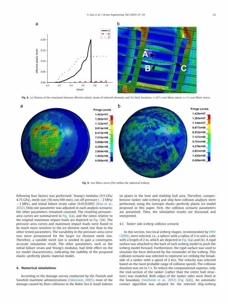
Fig. 8. (a) History of the simulated element effective plastic strain of selected elements and (b) their locations. t¼0.5 s von Mises stress, t¼1 s von Mises stress.
Fig. 9. von Mises stress [Pa] within the spherical iceberg.
Y. Gao et al. / Ocean Engineering 102 (2015) 27–39 33
interaction. Moreover, an eroding contact algorithm was utilizedfor the single iceberg interaction. The static and dynamic frictioncoefficients were both set to 0.15 in the aforementioned contacts;‘soft option 2’ was used to obtain more accurate results. Steelmaterials, i.e., S235 and S355 (NORSOK N-004, 2004), wereapplied to the ship side hull. S355 was applied to the upper andlower parts of the tanker side hull; the others parts, including theouter and inner shells, were treated with S235, which wasassumed to have a failure strain of 0.2 based on a typical shellelement length of 150 mm. The material and element details aresummarized in Table 2.
First, the simulated ship-spherical iceberg collision was ana-lyzed. Fig. 7 presents the results for the tanker side structure att¼0.5 s and t¼1 s. The effective plastic strain of the side structureis shown in the first row, which is followed by figures of the stresstriaxiality and von Mises stress. As shown in the first row of Fig. 7,the outer shell underwent substantial plastic deformation; themaximum effective plastic strain reached 0.2 at t¼1 s. Moreover,the outer shell was damaged and was penetrated by the end of thecollision. The membrane tensile and tear were the main failuremodes of the outer shell. The maximum positive stress triaxialityof the tanker side structure (which was as high as 0.666) wasobserved at the edge of the contact area. Furthermore, thenegative stress triaxiality of the tanker side fluctuated between�0.60 and �0.66. Regarding the von Mises stress of the tankerside structure, the largest stress was observed at the junction ofthe side stringer and the outer shell (426 MPa). To illustrate thecollision more clearly, a time series of the effective plastic strain onthree elements at various locations (as shown in Fig. 8(b)), namelythe outer shell, frame and stringer, are shown in Fig. 8(a). Theeffective plastic strain of element ‘A’ on the outer shell increaseduntil it reached the failure strain; thereafter, the element eroded.Furthermore, the effective plastic strain of element ‘B’ remained at
a relatively low level during the collision, which was probably dueto tearing of the outer shell. Element ‘B’ was pushed away and wasno longer involved in the collision process. Regarding element ‘C’,the effective plastic strain increased before remaining stable at0.13, indicating that this element did not interact with theneighboring elements in the later collision process. In summary,although the outer shell of the side structure was penetrated, theinner shell remained intact during the collision; therefore, no oilor gas leakage would have occurred in this simulation. However,the ship should be strengthened for voyages in ice-covered region.
With respect to the spherical iceberg model, the von Misesstresses at t¼0.5 s and t¼1 s are shown in Fig. 9. Only a few iceelements failed, indicating the high strength of this iceberg model.The ice load was primarily concentrated in critical zones (Fig. 9).These zones are scattered throughout the contact area, which ischaracteristic of ice mechanics. The largest von Mises stress in theiceberg was 14.3 MPa at t¼0.66 s.
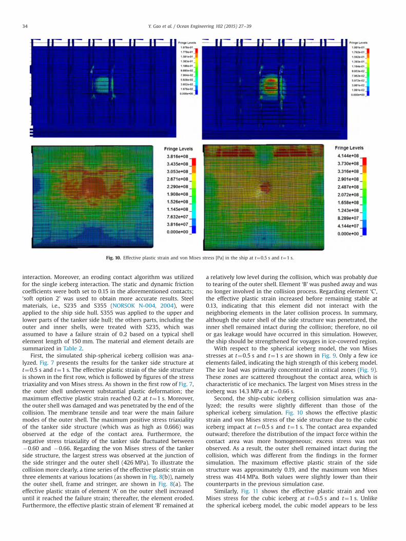
Second, the ship-cubic iceberg collision simulation was ana-lyzed; the results were slightly different than those of thespherical iceberg simulation. Fig. 10 shows the effective plasticstrain and von Mises stress of the side structure due to the cubiciceberg impact at t¼0.5 s and t¼1 s. The contact area expandedoutward; therefore the distribution of the impact force within thecontact area was more homogeneous; excess stress was notobserved. As a result, the outer shell remained intact during thecollision, which was different from the findings in the formersimulation. The maximum effective plastic strain of the sidestructure was approximately 0.19, and the maximum von Misesstress was 414 MPa. Both values were slightly lower than theircounterparts in the previous simulation case.
Similarly, Fig. 11 shows the effective plastic strain and vonMises stress for the cubic iceberg at t¼0.5 s and t¼1 s. Unlikethe spherical iceberg model, the cubic model appears to be less
Fig. 10. Effective plastic strain and von Mises stress [Pa] in the ship at t¼0.5 s and t¼1 s.
Y. Gao et al. / Ocean Engineering 102 (2015) 27–3934
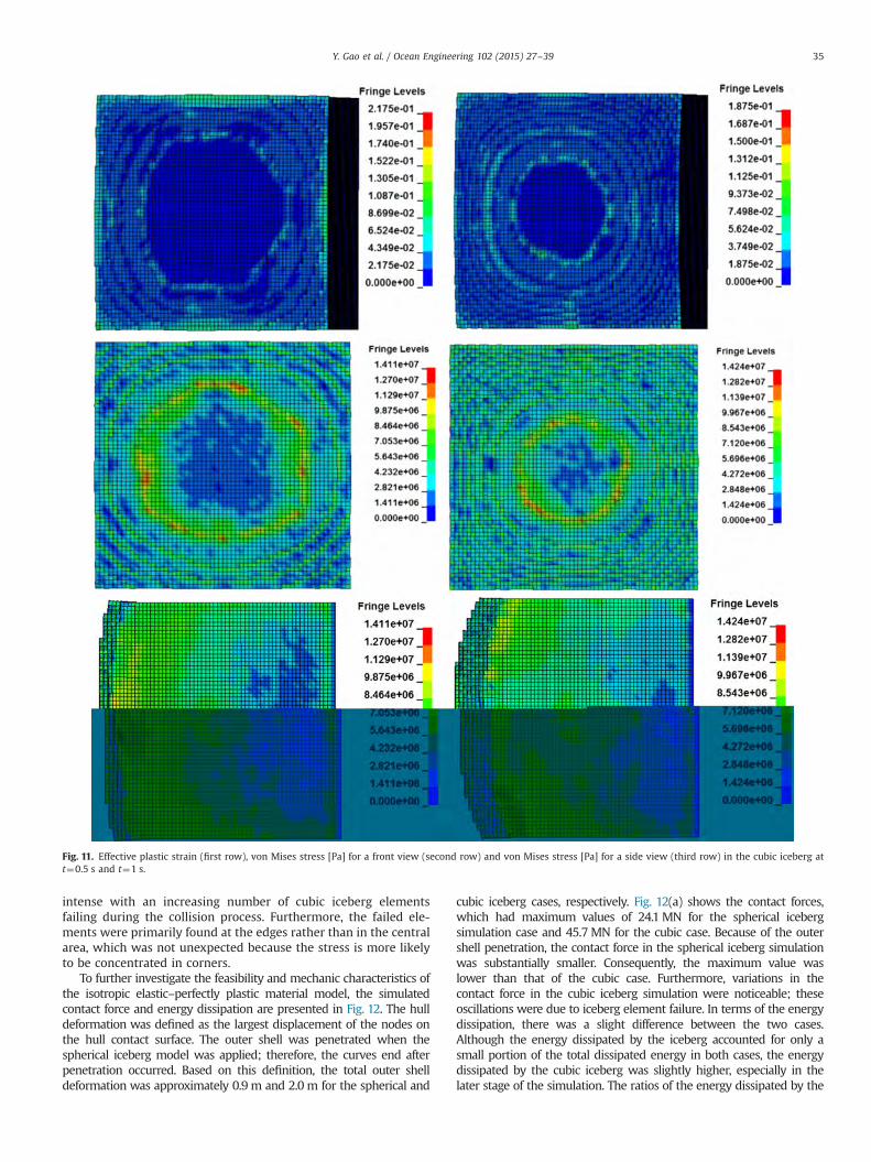
intense with an increasing number of cubic iceberg elementsfailing during the collision process. Furthermore, the failed ele-ments were primarily found at the edges rather than in the centralarea, which was not unexpected because the stress is more likelyto be concentrated in corners.
To further investigate the feasibility and mechanic characteristics ofthe isotropic elastic–perfectly plastic material model, the simulatedcontact force and energy dissipation are presented in Fig. 12. The hulldeformation was defined as the largest displacement of the nodes onthe hull contact surface. The outer shell was penetrated when thespherical iceberg model was applied; therefore, the curves end afterpenetration occurred. Based on this definition, the total outer shelldeformation was approximately 0.9 m and 2.0 m for the spherical and
cubic iceberg cases, respectively. Fig. 12(a) shows the contact forces,which had maximum values of 24.1 MN for the spherical icebergsimulation case and 45.7 MN for the cubic case. Because of the outershell penetration, the contact force in the spherical iceberg simulationwas substantially smaller. Consequently, the maximum value waslower than that of the cubic case. Furthermore, variations in thecontact force in the cubic iceberg simulation were noticeable; theseoscillations were due to iceberg element failure. In terms of the energydissipation, there was a slight difference between the two cases.Although the energy dissipated by the iceberg accounted for only asmall portion of the total dissipated energy in both cases, the energydissipated by the cubic iceberg was slightly higher, especially in thelater stage of the simulation. The ratios of the energy dissipated by the
Fig. 11. Effective plastic strain (first row), von Mises stress [Pa] for a front view (second row) and von Mises stress [Pa] for a side view (third row) in the cubic iceberg att¼0.5 s and t¼1 s.
Y. Gao et al. / Ocean Engineering 102 (2015) 27–39 35
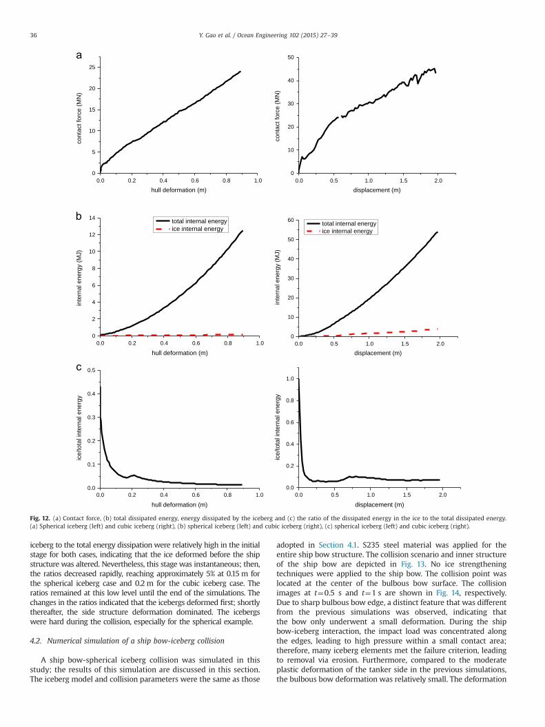
iceberg to the total energy dissipation were relatively high in the initialstage for both cases, indicating that the ice deformed before the shipstructure was altered. Nevertheless, this stage was instantaneous; then,the ratios decreased rapidly, reaching approximately 5% at 0.15m forthe spherical iceberg case and 0.2 m for the cubic iceberg case. Theratios remained at this low level until the end of the simulations. Thechanges in the ratios indicated that the icebergs deformed first; shortlythereafter, the side structure deformation dominated. The icebergswere hard during the collision, especially for the spherical example.
4.2. Numerical simulation of a ship bow-iceberg collision
A ship bow-spherical iceberg collision was simulated in thisstudy; the results of this simulation are discussed in this section.The iceberg model and collision parameters were the same as those
adopted in Section 4.1. S235 steel material was applied for theentire ship bow structure. The collision scenario and inner structureof the ship bow are depicted in Fig. 13. No ice strengtheningtechniques were applied to the ship bow. The collision point waslocated at the center of the bulbous bow surface. The collisionimages at t¼0.5 s and t¼1 s are shown in Fig. 14, respectively.Due to sharp bulbous bow edge, a distinct feature that was differentfrom the previous simulations was observed, indicating thatthe bow only underwent a small deformation. During the shipbow-iceberg interaction, the impact load was concentrated alongthe edges, leading to high pressure within a small contact area;therefore, many iceberg elements met the failure criterion, leadingto removal via erosion. Furthermore, compared to the moderateplastic deformation of the tanker side in the previous simulations,the bulbous bow deformation was relatively small. The deformation
0.0 0.2 0.4 0.6 0.8 1.00
5
10
15
20
25
cont
act f
orce
(MN
)
hull deformation (m)0.0 0.5 1.0 1.5 2.0
0
10
20
30
40
50
cont
act f
orce
(MN
)
displacement (m)
0.0 0.2 0.4 0.6 0.8 1.00
2
4
6
8
10
12
14
inte
rnal
ene
rgy
(MJ)
hull deformation (m)
total internal energyice internal energy
0.0 0.5 1.0 1.5 2.00
10
20
30
40
50
60
inte
rnal
ene
rgy
(MJ)
displacement (m)
total internal energyice internal energy
0.0 0.2 0.4 0.6 0.8 1.00.0
0.1
0.2
0.3
0.4
0.5
ice/
tota
l int
erna
l ene
rgy
hull deformation (m)0.0 0.5 1.0 1.5 2.0
0.0
0.2
0.4
0.6
0.8
1.0
ice/
tota
l int
erna
l ene
rgy
displacement (m)
Fig. 12. (a) Contact force, (b) total dissipated energy, energy dissipated by the iceberg and (c) the ratio of the dissipated energy in the ice to the total dissipated energy.(a) Spherical iceberg (left) and cubic iceberg (right), (b) spherical iceberg (left) and cubic iceberg (right), (c) spherical iceberg (left) and cubic iceberg (right).
Y. Gao et al. / Ocean Engineering 102 (2015) 27–3936
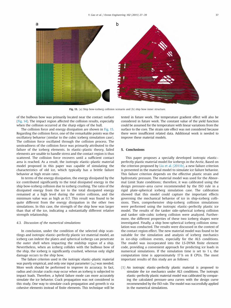
of the bulbous bow was primarily located near the contact surface(Fig. 14). The impact region affected the collision results, especiallywhen the collision occurred at the sharp edges of the hull.
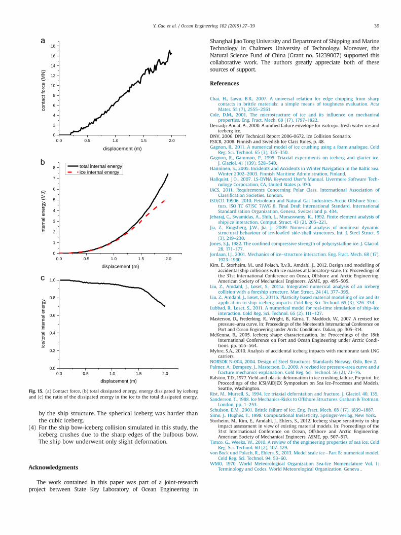
The collision force and energy dissipation are shown in Fig. 15.Regarding the collision force, one of the remarkable points was theoscillatory behavior (similar to the cubic iceberg simulation case).The collision force oscillated through the collision process. Theunsteadiness of the collision force was primarily attributed to thefailure of the iceberg elements. In elastic–plastic theory, failedelements are unable to handle stress and the contact region is thusscattered. The collision force recovers until a sufficient contactarea is reached. As a result, the isotropic elastic–plastic materialmodel proposed in this paper was capable of simulating thecharacteristics of old ice, which typically has a brittle failurebehavior at high strain rates.
In terms of the energy dissipation, the energy dissipated by theice contributed significantly to the total dissipated energy in theship bow-iceberg collision due to iceberg crushing. The ratio of thedissipated energy from the ice to the total dissipated energyremained at a high level during the entire collision, and theminimum value was as high as 0.7. This result was found to bequite different from the energy dissipation in the other twosimulations. In this case, the strength of the ship bow was largerthan that of the ice, indicating a substantially different relativestrength relationship.
4.3. Discussion of the numerical simulations
In conclusion, under the condition of the selected ship scan-tlings and isotropic elastic–perfectly plastic ice material model, aniceberg can indent the plates and spherical icebergs can penetratethe outer shell when impacting the midship region of a ship.Nevertheless, when an iceberg collides with the bulbous bow ofthe ship, the iceberg is significantly crushed, whereas only slightdamage occurs to the ship bow.
The failure criterion used in the isotropic elastic–plastic materialwas purely empirical, and only one input parameter (ε0) was needed.More work should be performed to improve its accuracy. In fact,radius and circular cracks may occur when an iceberg is subjected toimpact loads. Therefore, a hybrid failure mode can more accuratelysimulate the ice behavior. Crack propagation was not considered inthis study. One way to simulate crack propagation and growth is viacohesive elements instead of finite elements. This technique will be
tested in future work. The temperature gradient effect will also beconsidered in future work. The constant value of the yield functioncould be assumed for the temperature with linear variations from thesurface to the core. The strain rate effect was not considered becausethere were insufficient related data. Additional work is needed toimprove these material models.
5. Conclusions
This paper proposes a specially developed isotropic elastic–perfectly plastic material model for icebergs in the Arctic. Based onthe criterion proposed by Liu et al. (2011b), a new failure criterionis presented in the material model to simulate ice failure behavior.This failure criterion depends on the effective plastic strain andhydrostatic pressure. The material model was used for the Abnor-mal Limit State conditions; therefore, it was calibrated using thedesign pressure–area curve recommended by the ISO rule in arigid plate-spherical iceberg simulation case. The calibrationshowed that this model could capture the important effectsgoverning the mechanical behavior of ice in ship-iceberg colli-sions. Then, comprehensive ship-iceberg collision simulationswere performed using the isotropic elastic–perfectly plastic icemodel. The results of the tanker side-spherical iceberg collisionand tanker side-cubic iceberg collision were analyzed. Further-more, the different properties of these two iceberg shapes wereinvestigated. Finally, a ship bow-spherical iceberg collision simu-lation was conducted. The results were discussed in the context ofthe contact region effect. The new material model was found to besuitable for the simulation and analysis of iceberg mechanicsin ice-ship collision events, especially for the ALS conditions.The model was incorporated into the LS-DYNA finite elementcode, providing a convenient approach for predicting ice loads innumerical simulations. If the simulation time is set to 1 s, thecomputation time is approximately 17 h on 8 CPUs. The mostimportant results of this study are as follows:
(1) An isotropic elastic–perfectly plastic material is proposed tosimulate the ice mechanics under ALS conditions. The isotropicelastic–perfectly plastic material model was calibrated by compar-ing the calculated pressure–area curves with the design curverecommended by the ISO rule. Themodel was successfully appliedin the numerical simulations.
Fig. 13. (a) Ship bow-iceberg collision scenario and (b) ship bow inner structure.
Y. Gao et al. / Ocean Engineering 102 (2015) 27–39 37

(2) The iceberg properties simulated by the isotropic elast-ic–plastic material model were more sensitive to the iceelement size than the other examined parameters, such asthe initial failure strain and cut-off pressure.
(3) With respect to the tanker side-iceberg collisions simulated inthis study, a spherical iceberg can penetrate the plate. Largedeformation of the outer shell was also observed due to theimpact of a cubic iceberg. The energy was primarily dissipated
Fig. 14. von Mises stress [Pa] in the spherical iceberg (first row) and ship bow (second row); effective plastic strain in the ship bow (third row) at t¼0.5 s and t¼1 s.
Y. Gao et al. / Ocean Engineering 102 (2015) 27–3938
0.0 0.5 1.0 1.5 2.00
2
4
6
8
10
12
14
16
18co
ntac
t for
ce (M
N)
displacement (m)
0.0 0.5 1.0 1.5 2.00
1
2
3
4
5
6
7
8
inte
rnal
ene
rgy
(MJ)
displacement (m)
total internal energyice internal energy
0.0 0.5 1.0 1.5 2.00.0
0.2
0.4
0.6
0.8
1.0
ice/
tota
l int
erna
l ene
rgy
displacement (m)
Fig. 15. (a) Contact force, (b) total dissipated energy, energy dissipated by icebergand (c) the ratio of the dissipated energy in the ice to the total dissipated energy.
by the ship structure. The spherical iceberg was harder thanthe cubic iceberg.
(4) For the ship bow-iceberg collision simulated in this study, theiceberg crushes due to the sharp edges of the bulbous bow.The ship bow underwent only slight deformation.
Acknowledgments
The work contained in this paper was part of a joint-researchproject between State Key Laboratory of Ocean Engineering in
Shanghai Jiao Tong University and Department of Shipping andMarineTechnology in Chalmers University of Technology. Moreover, theNatural Science Fund of China (Grant no. 51239007) supported thiscollaborative work. The authors greatly appreciate both of thesesources of support.
References
Chai, H., Lawn, B.R., 2007. A universal relation for edge chipping from sharpcontacts in brittle materials: a simple means of toughness evaluation. ActaMater. 55 (7), 2555–2561.
Cole, D.M., 2001. The microstructure of ice and its influence on mechanicalproperties. Eng. Fract. Mech. 68 (17), 1797–1822.
Derradji-Aouat, A., 2000. A unified failure envelope for isotropic fresh water ice andiceberg ice.
DNV, 2006. DNV Technical Report 2006-0672. Ice Collision Scenario.FSICR, 2008. Finnish and Swedish Ice Class Rules, p. 48.Gagnon, R., 2011. A numerical model of ice crushing using a foam analogue. Cold
Reg. Sci. Technol. 65 (3), 335–350.Gagnon, R., Gammon, P., 1995. Triaxial experiments on iceberg and glacier ice.
J. Glaciol. 41 (139), 528–540.Hänninen, S., 2005. Incidents and Accidents in Winter Navigation in the Baltic Sea,
Winter 2002–2003. Finnish Maritime Administration, Finland.Hallquist, J.O., 2007. LS-DYNA Keyword User’s Manual. Livermore Software Tech-
nology Corporation, CA, United States p. 970.IACS, 2011. Requirements Concerning Polar Class. International Association of
Classification Societies, London.ISO/CD 19906, 2010. Petroleum and Natural Gas Industries-Arctic Offshore Struc-
turs, ISO TC 67/SC 7/WG 8, Final Draft International Standard. InternationalStandardisation Organization, Geneva, Switzerland p. 434.
Jebaraj, C., Swamidas, A., Shih, L., Munaswamy, K., 1992. Finite element analysis ofship/ice interaction. Comput. Struct. 43 (2), 205–221.
Jia, Z., Ringsberg, J.W., Jia, J., 2009. Numerical analysis of nonlinear dynamicstructural behaviour of ice-loaded side-shell structures. Int. J. Steel Struct. 9(3), 219–230.
Jones, S.J., 1982. The confined compressive strength of polycrystalline ice. J. Glaciol.28, 171–177.
Jordaan, I.J., 2001. Mechanics of ice–structure interaction. Eng. Fract. Mech. 68 (17),1923–1960.
Kim, E., Storheim, M., und Polach, R.v.B., Amdahl, J., 2012. Design and modelling ofaccidental ship collisions with ice masses at laboratory-scale. In: Proceedings ofthe 31st International Conference on Ocean, Offshore and Arctic Engineering.American Society of Mechanical Engineers. ASME, pp. 495–505.
Liu, Z., Amdahl, J., Løset, S., 2011a. Integrated numerical analysis of an icebergcollision with a foreship structure. Mar. Struct. 24 (4), 377–395.
Liu, Z., Amdahl, J., Løset, S., 2011b. Plasticity based material modelling of ice and itsapplication to ship–iceberg impacts. Cold Reg. Sci. Technol. 65 (3), 326–334.
Lubbad, R., Løset, S., 2011. A numerical model for real-time simulation of ship–iceinteraction. Cold Reg. Sci. Technol. 65 (2), 111–127.
Masterson, D., Frederking, R., Wright, B., Kärnä, T., Maddock, W., 2007. A revised icepressure–area curve. In: Proceedings of the Nineteenth International Conference onPort and Ocean Engineering under Arctic Conditions. Dalian, pp. 305–314.
McKenna, R., 2005. Iceberg shape characterization. In: Proceedings of the 18thInternational Conference on Port and Ocean Engineering under Arctic Condi-tions. pp. 555–564.
Myhre, S.A., 2010. Analysis of accidental iceberg impacts with membrane tank LNGcarriers.
NORSOK N-004, 2004. Design of Steel Structures. Standards Norway, Oslo, Rev 2.Palmer, A., Dempsey, J., Masterson, D., 2009. A revised ice pressure-area curve and a
fracture mechanics explanation. Cold Reg. Sci. Technol. 56 (2), 73–76.Ralston, T.D., 1977. Yield and plastic deformation in ice crushing failure, Preprint. In:
Proceedings of the ICSI/AIDJEX Symposium on Sea Ice-Processes and Models,Seattle, Washington.
Rist, M., Murrell, S., 1994. Ice triaxial deforntation and fracture. J. Glaciol. 40, 135.Sanderson, T., 1988. Ice Mechanics-Risks to Offshore Structures. Graham & Trotman,
London, pp. 1–253.Schulson, E.M., 2001. Brittle failure of ice. Eng. Fract. Mech. 68 (17), 1839–1887.Simo, J., Hughes, T., 1998. Computational Inelasticity. Springer-Verlag, New York.Storheim, M., Kim, E., Amdahl, J., Ehlers, S., 2012. Iceberg shape sensitivity in ship
impact assessment in view of existing material models. In: Proceedings of the31st International Conference on Ocean, Offshore and Arctic Engineering.American Society of Mechanical Engineers. ASME, pp. 507–517.
Timco, G., Weeks, W., 2010. A review of the engineering properties of sea ice. ColdReg. Sci. Technol. 60 (2), 107–129.
von Bock und Polach, R., Ehlers, S., 2013. Model scale ice—Part B: numerical model.Cold Reg. Sci. Technol. 94, 53–60.
WMO, 1970. World Meteorological Organization Sea-Ice Nomenclature Vol. 1:Terminology and Codes. World Meteorological Organization, Geneva .
Y. Gao et al. / Ocean Engineering 102 (2015) 27–39 39