an equivalent strut and tie model for steel plate shear
TRANSCRIPT

An equivalent strut and tie model for steel plate shear- wall systems
Arghya K Chatterjee, Anjan K Bhowmick & Ashutosh Bagchi Department of Building, Civil and Environmental Engineering, Concordia University
SUMMARY:
Steel Plate Shear Walls (SPSWs) have been accepted widely as an effective lateral load resisting system. For seismic performance evaluation of a multi-story building with SPSWs, detailed finite element models or a strip model can be used to represent the SPSW components. However, analysing such models often require significant effort for tall or medium height buildings. Using equivalent bracing to replace the infill plate can significantly simplify the analysis process. The focus of this article is to develop such a model to represent SPSWs in a building frame. This would facilitate a simplification to the structural modelling of large buildings with SPSWs in order to evaluate the seismic performance using regular structural analysis tools. The study shows that proposed model can capture the global behaviour of the structures quite accurately and potentially aid in performance-based seismic design of SPSW buildings.
Keywords: Strut-tie, Equivalent-bracing, Steel Plate Shear Wall
1. INTRODUCTION
The use of ductile steel plate shear wall (SPSW) is gaining grounds in modern construction. This is primarily because of its ability to resist lateral loads and add ductility to the performance of the structure. SPSW has a natural tendency to buckle due to the imperfection of geometry involved while welding or fabrication or distortion of frame or some other reason. Thus, resulting in change of load resisting mechanism from plane shear to inclined tension field. However, this buckling does not indicate failure as the tension field continues to provide a load path. This opens up an opportunity for developing a model where the complicated behaviour of the SPSW can be replaced by a simplified equivalent bracing system. The equivalent bracing system should have similar behaviour as that of the post buckling strength shown by the steel plate.
Current design and analysis of unstiffened SPSWs are based on post buckling strength of infill plates.

Thorburn et al. (1983) first introduced a design technique where the post buckling strength was used. They introduced “strip model”, which proved to be a reasonably acceptable method for analysis of SPSW systems. In this model, the plate is analysed as a number of pin-ended discrete strips capable of taking tension only and oriented along the principal tension direction, which is found by the principle of the least work. This model has been later criticized for under-estimating the stiffness (Driver, 1997). Also, this method becomes more complicated when cyclic push-pull load (like earthquake load) were being applied to the structure. For cyclic loadings, the orientation of strips in both tension and compression direction are necessary. This made the model more complex and time consuming when repeated analysis is necessary. Later, Finite Element Analysis (FEA) proved to be the most accurate way of modelling SPSW (Elgaaly et al., 1993, Driver et.al, 1997). Several modelling techniques like Berman and Bruneau (2005), Topkaya and Atasoy (2009) have been suggested in the past, where the efforts were mostly directed to developing a method for predicting more accurate behavior of SPSWs by FEA. Very few like Topkaya and Atasoy (2009) have made an attempt for developing a technique where analysis can be made faster and reasonably accurate. Speeding up the analysis without compromising the accuracy significantly is particularly important when a multi-storey model is analyzed under cyclic or dynamic loading due to earthquakes. Such structures may need to be analyzed for a suite of seismic ground motions in order to carry out a performance-based design.
Topkaya and Atasoy (2009) developed a hand calculation method to estimate the lateral stiffness of SPSW systems. They also proposed an equivalent truss model to represent the SPSW structural system. The abovementioned truss model is a modification over a model suggested earlier by Thorburn et al. (1983). Topkaya and Atasoy (2009) suggested that along with an equivalent truss model, the boundary elements have to be stiffened by increasing the area of the boundary according to their suggested formula. Both the abovementioned methods involve significant hand computations which may affect convenience of the applications of those models. Also, reconstruction of the boundary elements involves additional time. In the present work, an attempt has been made to develop a simplified virtual model that would represent the complicated SPSW system in a global sense. Initially, a set of detailed FEA models have been developed and validated with available experimental work. These models are the modified with the proposed equivalent bracing system to represent the infill plate behaviour. The global and storey-wise push-over curves generated by SPSW system and equivalent braced frame model are compared to validate the proposed bracing model. A set of SPSW frames of single, four and six storey height has been considered here.
2. SELECTION OF THE FINITE ELEMENT MODELLING TECHNIQUE
There is a wide range of choices available for modelling technique for FEA analysis. In selecting the appropriate modelling techniques one has to consider both the accuracy of result and the efficiency of analysis. As mentioned earlier, the commercial finite element analysis software, ABAQUS (Abaqus, 2011) has been used here to implement the proposed bracing model. It is observed that ABAQUS/Implicit models generally lead to convergence problem when the problem is highly non-linear. With appropriate control on the kinetic energy, ABAQUS/Explicit can be used for the analysis for quasi-static loading (Bhowmick et al., 2010). In the explicit model there is a choice of iterative method and central difference method. The central difference method is used here as it provides a conditionally stable solution. However, the time increment needs to be extremely small to achieve reliable results (Bhowmick et al., 2010). Also, if only the stiffness proportional damping is included, the stability of the solution is affected. The implicit model available in ABAQUS uses the Hilber-Hughes-Taylor operator, which is an extension of the trapezoidal rule (Hilber et al., 1978). This
operator is unconditionally stable, which is of great value when studying nonlinear structural systems. With implicit time integration, sometimes it is difficult to obtain a solution for a static analysis when the system is highly nonlinear. However, nonlinearities are usually more easily accounted for in dynamic analysis than in static analysis because the inertia terms provide mathematical stability to the system, making the method more robust. In implicit, results are considered reliable only when at every time step increment the work done by external force is equal to the internal energy of the system, whereas the kinetic energy remains bounded and small.
3. CHARACTERISTICS OF THE FINITE ELEMENT MODEL
3.1. Geometry and the initial conditions
A set of FEA models for SPSW systems has been developed based on available experimental works (Lubell et al. (2000), Kharrazi (2005), Neilson (2010)). In developing the models, attention has been given to the details of the specimens used in the respective tests. Fish plate required to connect the plate with the boundary elements in the tests, was not modelled as no significant contribution was observed in the result. Initial geometric imperfection in a plate has been introduced by defining an out of the plane deformation proportional to the first buckling mode of the plate. The magnitude of initial imperfection was assumed to be twice the thickness of the plate. The magnitude of the imperfection does not seem to have any significant impact on the capacity of a SPSW system provided it remains close to the chosen value. For the equivalent brace models developed here, the plate is replaced by a set of non-concentric diagonal truss member.
3.2. Element selection
For the detailed FE model, all the elements of SPSWs (plate, beam-column flange and web) have been modelled using the standard shell element S4R, available in ABAQUS. Finite member stains and large rotations are accounted for by the shell element. It has six degrees of freedom defined in its global co-ordinates (three translations and three rotations defined along the x, y, z axes). The S4R element is based on an iso-parametric formulation. It uses one integration point on its mid-surface to form the element internal force vector. With fine meshing the chance of local distortion of elements become negligible. For the equivalent bracing model, the braces are modelled using the three dimensional truss element T3D2, available in ABAQUS element library. In this case, an equivalent area of cross section of the brace has to be estimated.
3.3. Material properties
The material properties used are the same obtained from tension coupon test performed in the available experimental studies. The elasto-plastic stress-strain curves are used for the boundary elements and plate. For equivalent bracing system, the property of the boundary elements are modified to compensate for the loss of stiffening effect of the plate around the boundary elements when it is replaced by the equivalent bracing system. The Von-Mises yield criterion has been adopted for the analysis. The associated flow rule is used to obtain the plastic strain increment. For the monotonic pushover analysis, a nonlinear isotropic hardening model has been used.
4. ANALYSIS CONTROLS
For single storey structures, displacement control solution strategy has been used. The desired

displacement is applied in steps at the key loading point. The total base shear is then calculated. The total base shear verses the boundary displacement gives the load-displacement (pushover) curve. Displacement control is difficult to implement for the multi-storey structures as the proportion of loading and displacement at each storey keep changing while the structure starts yielding. Thus, in case of multi-storey structures, load control method with very small load steps has been used.
5. AVAILABLE EXPERIMENTAL STUDIES
The finite element model has been validated by comparing the results of the available experimental studies. The same validated model has been later used for the parametric study leading to the development of the equivalent bracings system. Neilson (2010) has conducted a detailed study mainly to define the connection requirements while using cold form SPSWs. In that study, a set of single storey moment resisting frames with very thin steel plate infill were tested. Kharrazi (2005) conducted a detailed review of the existing reports on SPSW and conducted an experiment on cold form SPSW. To avoid local failure Kharrazi (2005) used HSS sections in column. Lubell et al. (2000) also conducted several experiments with steel plate shear walls to characterize their behaviour. The results of these experimental studies have been used here to calibrate the proposed equivalent bracing system.
5.1. Lubell et al., 2000
Lubell et al. (2000) studied the sensitivity of various parameters responsible for the behaviour of single storey SPSW systems. Three models were studied through lab scale experiments and FEA models. One of the three specimens has been considered in the present study for the validation purpose. In this case, the aspect ratio of the frame is maintained as 1:1. Material properties obtained by the tension coupon test in the original study have been used in the current model. From the tension coupon test, yield stress of the frame is reported to be 380MPa and that of the infill plate is 320MPa. The plate thickness is 1.5 mm, and the boundary elements are taken as S75x8.
5.2. Kharrazi, 2005
Kharrazi (2005) tested three some single storey SPSW systems with light-gauge infill plates. Instead of using W-sections for the columns, Hollow Steel Sections (HSS) were used. The primary reason for that was to avoid local buckling. However, for beams normal W-section was used as local buckling was not a problem with the beams. A monotonic pushover analysis was conducted with a lateral load applied along the centre-line of the top beam. As earlier, an initial imperfection of 2w (=1.4mm) was used. Kharrazi (2005) tested two similar frames with plate infill with different materials for the plate. For the first one (designated as DSPW1) the yield strength of the plate was considered as 200Mpa and that of the second one (designated as DSPW2) as 150Mpa. Both the samples have been used here to validate the corresponding FE models which are then used for developing an equivalent bracing system. In the present analysis, the displacement of a given node is monitored and the analysis is terminated when the maximum lateral deflection has been reached (e.g., 115 mm for DSPW1 and 95 mm for DSPW2). The maximum displacements as mentioned above were obtained from the envelope of hysteresis curves of the physical test.
5.3. Neilson, 2010
Nielson (2010) tested a single storey SPSW specimen designed based on CAN/CSA S16 – 01 (CSA, 2009). Yield strength of the material for the boundary elements and the palate are assumed to be 380 Mpa 275 MPa, respectively as reported in Neilson (2010). Additionally, an imperfection of 2w (w is

the plate thickness, which is 0.98 mm, in this case) has been used. As in the test, displacement loading has been applied through the centre line of the top beam level. The displacement is increased to a maximum value of 70 mm as obtained from the envelope of hysteresis curve of physical test. The geometry and the element mesh of the SPSW are shown in Fig. 5.1.
Figure 5.1: Sketch and FEA-mesh of the specimen tested by Neilson, 2010
(a) (b)
(c) (d)
Figure 5.2: Comparison of the results of the FEA and experimental studies for single storey structures
5.4. Comparison of the results of the FEA and experimental studies
Fig. 2(a) shows the pushover curve obtained from the experimental and numerical (labelled “Author-FEA”) studies presented in Lubell et al. (2000) and the current FEA model (labelled “plate”). It is observed that the results of the current FEA model are comparable to the experimental results. Fig. 2(b) shows the results of the experimental work presented in Neilson (2010). The figure indicates that the finite element model predicts the initial stiffness and post-yield response of the shear wall very well. The ultimate capacity of the specimen is over estimated by less than 2%. Fig. 5.2 (c & d) show the comparison between the models developed for validation in this paper and the physical models tested by Kharrazi (2005). Both the models (DSPW1 and DSPW2) show excellent agreement for the initial stiffness. In DSPW2 the capacity estimated works quite well by the FEA model, while in DSPW1, the FEA model underestimates the capacity by about 3.4%. Fig. 5.2 also shows the pushover curves obtained using the equivalent braced frame models which will be discussed later in this article.
6. PARAMETRIC STUDY
The validated FEA models of the available experimental studies and another single storey model
W200x31
W200x31
W20
0x3
W20
0x31
1795
2440
Plate Thickness 0.98mm

(referred here as “sample” SPSW) presented in Bhowmick et al. (2011) have been used here for a detailed parametric study. The main purpose of this study is to determine the relationship between the area of the tension brace to the lateral stiffness of the system such that and equivalent brace-area can be formulated to represent the corresponding SPSW system giving the same stiffness properties and the overall behaviour remains the same. The parameters that have been considered in this analysis are aspect ratio of the plate, area of the bracing, and the thickness of the infill plate. These parameters are varied arbitrarily to assess their effects on the structural system. The push over curve developed for each varying parameter has been idealized as a bilinear curve. The point where the bilinear curve changes its slope is considered to be the yield point. When the variation of the plate thickness and the aspect ratio is considered, the yield point of the SPSW system is normalized to that of the bare frame model. Fig. 6.1(a) shows the change in the yield strength of the frame with variation in the plate thickness. However, the slope of the line is observed to be dependent on the strength of the boundary frame. Similar behaviour has been observed for the aspect ratio of the plates (Fig. 6.1b). Finally, the contribution of area of the bracing is examined as shown in Fig. 6. From the co-ordinates of the yield points on the equivalent bilinear pushover curve, the apparent lateral stiffness of the system can be calculated by dividing the yield force by the overall displacement at the yield point. The stiffness is normalized to the stiffness calculated in the same way for the bare frame model. When the normalized stiffness is plotted against the varying area of the equivalent bracing then up to a limit linear relation with area is observed in all cases. Beyond that limit the behaviour is non-linear indicating an early failure of the boundary members (Fig. 6.2). It is observed in case of the model in Lubell et al. (2000) (Fig. 6.2) that after the linear range, the stiffness of the braced frames changes abruptly at higher magnitudes of the bracing area. This may be attributed to local yielding of the boundary frame. Thus, it can be concluded that while the boundary elements need to be strong enough to avoid local failure, mere increase in the area of the equivalent bracings may not be sufficient to achieve the desired stiffness for corresponding SPSWs.
Figure 6.1: Parametric study with varying (a) plate thickness (b) aspect ratio
Figure 6.2: Parametric study on normalized stiffness of the model with varying area of equivalent brace
7. DEVELOPMENT OF EQUIVALENT BRACE MODELS
7.1. Cross sectional area
From the parametric study it is clear that area of the brace affects the stiffness of the system linearly up to a certain limit. Also, the plate thickness and aspect ratio have almost linear relationship with the
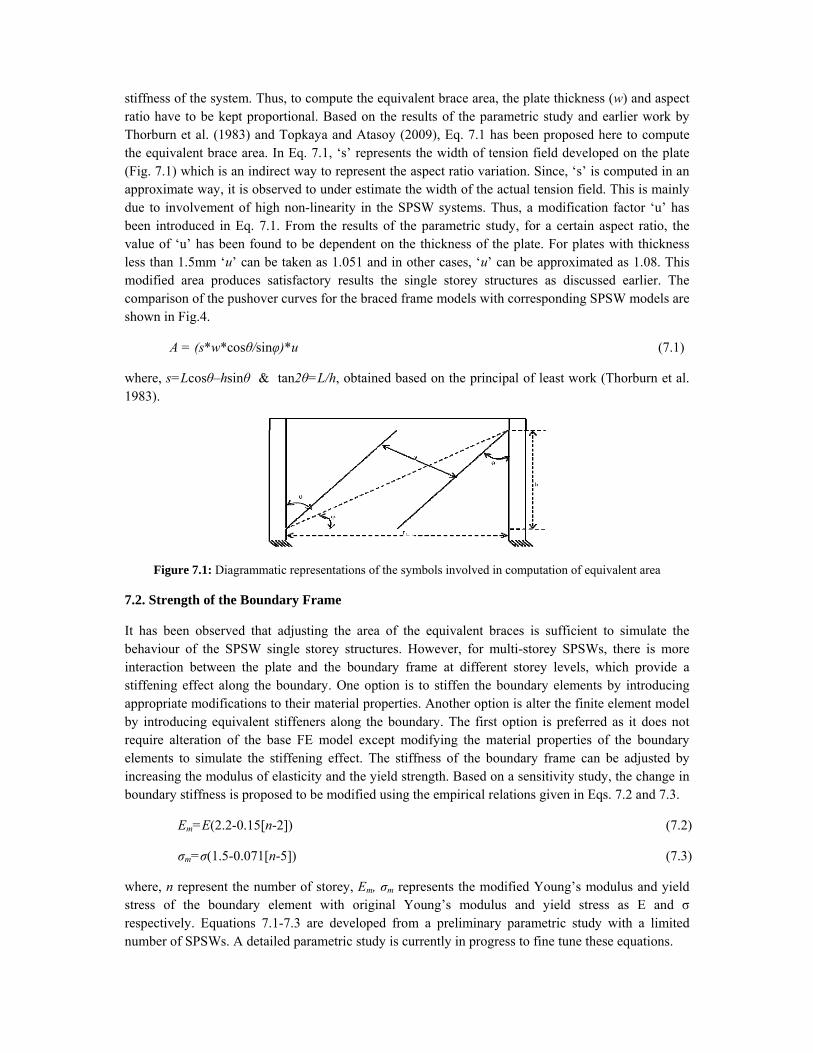
stiffness of the system. Thus, to compute the equivalent brace area, the plate thickness (w) and aspect ratio have to be kept proportional. Based on the results of the parametric study and earlier work by Thorburn et al. (1983) and Topkaya and Atasoy (2009), Eq. 7.1 has been proposed here to compute the equivalent brace area. In Eq. 7.1, ‘s’ represents the width of tension field developed on the plate (Fig. 7.1) which is an indirect way to represent the aspect ratio variation. Since, ‘s’ is computed in an approximate way, it is observed to under estimate the width of the actual tension field. This is mainly due to involvement of high non-linearity in the SPSW systems. Thus, a modification factor ‘u’ has been introduced in Eq. 7.1. From the results of the parametric study, for a certain aspect ratio, the value of ‘u’ has been found to be dependent on the thickness of the plate. For plates with thickness less than 1.5mm ‘u’ can be taken as 1.051 and in other cases, ‘u’ can be approximated as 1.08. This modified area produces satisfactory results the single storey structures as discussed earlier. The comparison of the pushover curves for the braced frame models with corresponding SPSW models are shown in Fig.4.
A = (s*w*cosθ/sinφ)*u (7.1)
where, s=Lcosθ–hsinθ & tan2θ=L/h, obtained based on the principal of least work (Thorburn et al. 1983).
Figure 7.1: Diagrammatic representations of the symbols involved in computation of equivalent area
7.2. Strength of the Boundary Frame
It has been observed that adjusting the area of the equivalent braces is sufficient to simulate the behaviour of the SPSW single storey structures. However, for multi-storey SPSWs, there is more interaction between the plate and the boundary frame at different storey levels, which provide a stiffening effect along the boundary. One option is to stiffen the boundary elements by introducing appropriate modifications to their material properties. Another option is alter the finite element model by introducing equivalent stiffeners along the boundary. The first option is preferred as it does not require alteration of the base FE model except modifying the material properties of the boundary elements to simulate the stiffening effect. The stiffness of the boundary frame can be adjusted by increasing the modulus of elasticity and the yield strength. Based on a sensitivity study, the change in boundary stiffness is proposed to be modified using the empirical relations given in Eqs. 7.2 and 7.3.
Em=E(2.2-0.15[n-2]) (7.2)
σm=σ(1.5-0.071[n-5]) (7.3)
where, n represent the number of storey, Em, σm represents the modified Young’s modulus and yield stress of the boundary element with original Young’s modulus and yield stress as E and σ respectively. Equations 7.1-7.3 are developed from a preliminary parametric study with a limited number of SPSWs. A detailed parametric study is currently in progress to fine tune these equations.

8. PERFORMANCE OF THE EQUIVALENT BRACE MODEL
8.1. Single storey
The equivalent bracing model for a set of single storey SPSW systems has been validated earlier as shown in Fig. 5.2. The model has been tested further using another single story structure taken from Bhowmick et al. (2011) which has been used earlier for the parametric study. The summary of the frame elements and plate are given in Table 8.1. Initially the push-over curve has been developed with the infill plate, and then the model is modified replacing the plate with equivalent diagonal braces. The pushover curves obtained from the two models (i.e., plate and bracing) as shown in Fig.8.1 are in excellent agreement.
TABLE 8.1: Details for the sample single storey SPSW
Beam Column Plate
Section E (MPa) σy(MPa) Section E(MPa) σy(MPa) Thickness E(MPa) σy(MPa)
W530x272 200,000 350 W360x509 200,000 350 3 mm 200,000 385
Figure 8.1: Sample test of equivalent braced model to represent SPSW
8.2. Multi-storey
8.2.1. Selection of Structure
A four and a six storey buildings are considered here to evaluate the performance of the proposed modelling technique for SPSW systems. Both buildings have identical plan with a total plan area of 2014 m2 and represent hypothetical office buildings which are assumed to be located in Vancouver.
Table 8.1: Details of the structural elements of the 4-storey and 6-storey light-gauge shear wall systems
Storey 6-storey wall 4-storey wall Plate thickness (mm) Column Plate thickness
(mm) Column
1 3 W360x744 2.75 W360x6342 3 W360x744 2.5 W360x6343 2.75 W360x382 2 W360x3824 2 W360x382 1 W360x3825 1.5 W360x262 6 1.0 W360x262
The building has two identical shear walls to resist lateral forces in each direction; thus, each shear wall will resist one half of the design seismic loads. For simplicity, torsion is neglected. Each shear wall panel is 7.6 m wide, measured from centre to centre of columns, and has an aspect ratio of 2.0 (storey height of 3.8 m). The building is assumed to be founded on rock (site class B according to NBCC 2010). The buildings have been designed using the according to the using the seismic

provision of NBCC 2010 (NRC 2010), and the boundary members are proportioned according to CSA-S16-09 (CSA, 2009) to develop the full capacity of light-gauge infill plates. For both 4-storey and 6-storey light-gauge shear walls, a beam size of W610x372 has been selected at the base of the walls to anchor the forces developed due to the yielding of the bottom storey infill plates. For all other storeys, the beam section of W460x158 has been utilized. CAN/CSA-S16-09 (CSA, 2009) also has provisions for the stiffness of the columns to ensure the development of an essentially uniform tension field in the infill plate. The final column and beam sections satisfy these requirements Table 8.1 presents the final columns and plate thicknesses for the four and six storey SPSWs.
8.2.2. Multi-storey braced model
Nonlinear static push-over analysis has been carried out for both the four and the six storey structures. In the SPSW model the steel plates are then replaced by the equivalent bracings and a similar analysis is carried out. The modulus of elasticity of the boundary elements has been increased from 200GPa to 380 GPa for the four-storey structure, and 320GPa for the six storey structure (as discussed in Sec 7.2). Also, the yield stress is increased from 350MPa to 550MPa and 500MPa for four and six-storey structures, respectively. It has been observed from Fig. 8.2 (4-storey) and Fig. 8.3 (6-storey) that the storey-wise pushover curves from all the models are close to each other. The equivalent bracing system is found to under-estimate the initial stiffness slightly, and over-estimate the post yielding strength at the lower stories slightly .
Figure 8.2: Pushover at each floor height for the four-storey structure
Figure 8.3: Pushover at each floor height for the six-storey structure The performance of the braced model is further investigated by comparing quasi-static cyclic analysis results, for the selected 4-storey SPSW, from the simplified braced model with that from the detailed FE model (with infill plate). A cyclic displacement history has been applied by increasing the displacement of the first panel by an amount equal to a multiple of the yield displacement. The first panel yield displacement is obtained from a pushover analysis. The hysteresis curve obtained from the braced model is compared with that from the detailed shell element model (Fig. 8.4).

Figure 8.4: Hysteresis curves for the 4-storey SPSW 9. CONCLUSION
From the pushover curves it can be inferred that the global behavior of SPSWs can be represented by simplified equivalent bracing system to a good extent. This lends to simplify the structural model of a SPSW system where instead of a detailed FE model, simple beam column elements for the boundary frame and truss elements for the bracings can be used. The simplified modeling technique would be particularly useful when the structure needs to be analyzed for cyclic loads or a suite of earthquake ground motions. Although the efficiency for such analyses has not been demonstrated here, the work is in progress. The study shows that proposed model can capture the global behavior of the structures quite accurately and aid in performance-based seismic design of SPSW buildings. A further quantitative representation of the contribution of SPSWs on strengthening of the boundary system needs to be performed to formalize the extent to which the boundary elements are to be strengthened.
REFERENCES
Abaqus, (2011). Abaqus Theory Manual, Version 6.11., Dassault Systèmes. Berman J.W. and Bruneau M. (2005). Experimental Investigation of Light-Gauge Steel Plate Shear. Journal of
Structural Enginering 131(2): 259–267. Bhowmick A.K., Grondin G.Y. and Driver R.G. (2011). Estimating fundamental periods of steel plate shear
walls. Journal of Structural Enginering 33: 1883–1893. Bhowmick A.K., Grondin G.Y. and Driver R.G. (2010). Performance of Type D and Type LD steel plate.
Canadian Journal of Civil Engineering,37: 88-98. CSA. (2009). Limit states design of steel structures. CAN/CSA-S16-09, Canadian Standards Association,
Toronto, Ontario, Canada. Driver R.G., Kulak G.L.,Kennedy D.J.L. and Elwi A.E. (1997). Seismic behaviour of steel plate shear walls.
Dept. of Civil and Env. Eng., University of Alberta, Edmonton, Alberta: Structural Eng. Report No. 215. Elgaaly M., Caccese V. and Du C. (1993). Post-buckling behavior of steel-plate shear walls under cyclic loads.
Journal of Structural Engineering 119(2): 588–605. Hilber H.M., Hughes T.J.R. and Taylor R.L. (1978). Collocation, dissipation and ‘overshoot’ for time
integration schemes in structural dynamics. Earthquake Engineering & Structural Dynamics 6(1): 99-117. Kharrazi M.H.K. 2005. Rational method for analysis and design of steel plate walls. Ph.D. thesis, University of
British Columbia,. Lubell S., Prion H. G. L., Ventura C. E. and Rezai M. (2000). Unstiffened steel-plate-shear wall performance
under cyclic loading. Journal of Structural Enginering 126(4): 453-460. Neilson D.A.H. (2010). Welding of light gauge infill panels for steel plate shear walls. Department of Civil and
Environmental Engineering, M.Sc. thesis, University of Alberta, Edmonton, Alberta, NRC. (2010). National Building Code of Canada (NBCC). Canadian Commission on Building and Fire Codes,
National Research Council of Canada, Ottawa, Ontario, Canada. Thorburn L.J., Kulak G.L. and Montgomery C.J. (1983). Analysis of Steel Plate Shear Walls. Department of
Civil Engineering, University of Alberta, Edmonton, Alberta: Structural Engineering Report No. 107. Topkaya C. and Atasoy M. 2009. Lateral stiffness of steel plate shear wall systems. Thin-Walled Structures, 47:
827–835.