an experimental method for approximating the bulk ... · an experimental method for approximating...
TRANSCRIPT

An Experimental Method for Approximating the Bulk Viscosity of Olivine+Basalt
Aggregates
Marshall I. Sundberg Senior Integrative Exercise
March 11, 2003
Submitted in partial fulfillment of the requirements for a Bachelor of Arts degree from Carleton College, Northfield,
Minnesota.
Table of Contents
Abstract 1. Introduction …………………………………………………………………1 2. Compaction: The Basics …………………………………………………...3 3. Compaction: the Special Case of a Sphere…………………………………7 4. Experimental Rationale…………………………………………………….. 11
4.1 Theoretical Considerations………………………………………………11 4.2 Gravity Settling, Differential Stress and the Question of Finite Strain…13
4.3 Bulk vs. Shear Viscosity……………………………………………….. 13 4.4 Why Compaction Length Matters……………………………………… 14
5. Experimental Design ………………………………………………………..15 5.1 PI-950…………………………………………………………………...16
5.2 PI-951………………………………………………………………….. 16 5.3 PI-984………………………………………………………………….. 16 5.4 PI-988………………………………………………………………….. 16 5.5 PI-997………………………………………………………………….. 17
6. Experimental Details………………………………………………………...17 6.1 Drying and Cold Press………………………………………………… 17 6.2 Hot Press………………………………………………………………. 18
6.3 Deformation: Pure Shear……………………………………………….19 6.4 Deformation: Simple Shear……………………………………………. 19
6.5 Paterson Vessel ………………………………………………………...19 6.6 Sectioning and Polishing ………………………………………………22 6.7 Optical Microscopy…………………………………………………….22 6.8 Binarization……………………………………………………………. 23 6.9 Contouring ……………………………………………………………. 23
7. Results ………………………………………………………………………24 7.1 PI-950 …………………………………………………………………. 25 7.2 PI-951 …………………………………………………………………..27 7.3 PI-984 …………………………………………………………………. 28 7.4 PI-988……………………………………………………………………29 7.5 PI-997………………………………………………………………….. 31 8. Discussion………………………………………………………………….. 32 9. Conclusions/Future Direction………………………………………………. 36 Acknowledgements…………………………………………………………. 38
Appendices ………………………………………………………………… 39 I. Rheological Data ……………………………………………………… 39 II. Predictions of melt redistribution from Compaction Theory……………39 III. Techniques of Numerical Image Analysis……………………………..41
IV. Some Notes on Scaling ……………………………………………….44 Table I. Experimental Data………………………………………………… 47 References…………………………………………………………………. 48

An Experimental Method for Approximating the Bulk Viscosity of Olivine+Basalt
Aggregates
Marshall Sundberg March 11, 2003
Advisors: David Kohlstedt and Dave Bice
The mechanical behavior of partially molten rocks plays is central in understanding the geodynamical behavior of the upper mantle. This understanding has been limited by difficulties in measuring the viscosity of the solid phase in these aggregates. Consequently, to investigate the ratio between the bulk and shear viscosity in partially molten aggregates, a series of high pressure, high temperature rock deformation experiments have been preformed on synthetic olivine+basalt aggregates containing small zirconia inclusions. This ratio measures the resistance a partially molten aggregate exerts to a volumetric change in melt fraction versus its resistance to shear deformation. The redistribution of the fluid phase around these inclusions has been quantified and compared to the theoretical results predicted by compaction theory. The samples were composed of either 95% San Carlos Olivine+5% MORB, 93% San Carlos Olivine+5% MORB+2% FeS, or 95% Beaver Bay Anorthite+5% MORB. Samples were deformed to strains of 10-20% in triaxial compression or 250% strain in simple shear. These experiments were conducted at P=300 MPa and T=1250 C for the olivine-rich samples, or T=1200 C for the anorthite-rich samples. Samples deformed to 20% strain in pure shear show preferential redistribution of the melt phase into lobes of high melt concentration (1.5- 2 times initial concentration) on either side of the inclusion and zones of low melt fraction (~0.5 times initial concentration) directly above and below the inclusion suggesting that the ratio of bulk to shear viscosity is low. Deviations from predicted results prevent more precise measurements. The addition of FeS to the olivine+MORB samples reduces permeability leading to a smaller compaction length. The replacement of olivine by anorthite reduces the shear viscosity of the solid phase with a corresponding decrease in compaction length. These small compaction length samples exhibit a nearly homogenous melt distribution with little or no partitioning into a pressure shadow microstructure. These observations suggest that compaction length is a limiting factor in the formation of pressure shadows. Olivine+MORB samples deformed in simple shear to high strains show the most pronounced melt redistribution. These observations also suggest that the compaction theory, in its present form, does not fully explain the dynamics of local deformation in compacting flows.
Keywords: deformation, compaction, experimental studies, viscosity, models
1
1. Introduction
The migration and transport of fluids is central to understanding a wide variety of
Earth processes, including crustal metamorphism, hydrology, and mantle dynamics. In
the mantle, the separation of a melt from a partially molten aggregate and its subsequent
transport plays an important role in understanding the dynamics of mantle plumes and
mid-ocean ridges. Geochemical evidence suggests that this melt must travel in high
permeability pathways so that the melt migrates faster than it can equilibrate with the
surrounding asthenosphere (Spiegelman, 1992). Several mechanisms have been
proposed to create these melt conduits. They range from chemical methods such as the
reaction infiltration instability (Aharonov, 1995), percolation through a permeable and
viscous rock (Kelemen et al., 1997) to open flow through discrete fractures (Richardson,
1996).
Mechanical models of melt migration require that the melt phase be separated
from its solid residuum to produce a nearly crystal free melt. Geodynamic models of this
phenomenon often require the use of two-phase flow equations. These models recognize
that the fundamental question in melt migration is one of two-phase flow, involving the
interactions between a porous and deformable solid matrix and its interstitial melt. The
simplest dynamic formulation is that the melt phase, being less dense than the
surrounding solid matrix, will tend to rise due to its own buoyancy. Therefore, the
problem becomes one of porous flow where the dynamics of melt segregation are
controlled not only by the physical properties of the fluid melt phase, but also necessarily
by the physical properties of the solid phase. Although the majority of the research on
compaction has focused on its application to large-scale igneous melting processes, its

2
applicability spans the earth sciences. Hydrology is principally concerned with the
movement of water through a porous medium, as is Sedimentology concerned with the
expulsion of water from porous sediments. The transport of fluids through rocks during
metamorphism may be controlled by compaction. Furthermore, the segregation and
growth of a planetary outer core may be governed by the physics of compaction. The
physics of this compaction process has been studied extensively over the past twenty
years, and several theoretical models have been developed (Bercovici et al., 2001b;
Fowler, 1985; Fowler, 1990; McKenzie, 1984; Scott and Stevenson, 1986; Scott, 1989).
These models have been used to investigate geochemical trends in Hawaiian basalts, the
process of melt segregation from a mantle plume (Richter and McKenzie, 1984), the role
of compaction in explaining melt transport towards mid-ocean ridges (Spiegelman and
McKenzie, 1987), shear localization, plate boundary formation (Bercovici et al., 2001a),
the composition of partial melts in the mantle, (Ribe, 1985), the geochemical effects of
the movement of small melt fractions in the mantle (McKenzie, 1989), and the
development of high permeability pathways in partially molten rocks undergoing shear
deformation (Holtzman et al. 2002). While the study of the compaction process has been
largely theoretical, experimental studies have produced results that support the theory
(Riley, 1991; Riley and Kohlstedt, 1990).
To apply these models, it is necessary to understand how various physical
properties of the partially molten rock influence its compacting behavior. Describing the
viscosity of the solid phase has been particularly controversial. McKenzie (1984) and
Stevenson (1986) have argued that the solid viscosity must be described in terms of a
shear viscosity of the solid grains and a bulk viscosity of the entire aggregate. The

3
concept of a bulk viscosity has been around at least since the 1960s (Batchelor, 1967).
To date, there are no published measurements of a partially molten aggregate’s bulk
viscosity, and many workers assume that it either does not exist or is identical to shear
viscosity. Recognizing this difficulty, Bercovici et.al. (2001) argued that a single
viscosity term is capable of describing all forms of deformation. Consequently, they
have argued that a bulk viscosity term is unnecessary and they formulated a two-phase
flow model that does not require this term. To date this argument has been exclusively
theoretical, no experimental attempts to measure the bulk viscosity of a partially molten
rock have been made.
Consequently, the central purpose of this paper is to begin the process of
measuring the bulk viscosity of a partially molten aggregate. Synthetic ultramafic rocks
with compositions, and under P/T conditions characteristic of the upper mantle, have
been subjected to a series of high pressure, high temperature deformation experiments.
The results of these experiments are then interpreted in light of compaction theory and
they place broad constraints on the bulk viscosity of mantle-type rocks.
2. Compaction: The Basics
The compaction model used in this paper, developed by McKenzie (1984), states
that in order to understand compacting behavior, it is necessary to have values for several
parameters. Consider, for example, a two-phase column of partially molten rock with a
rigid lower and upper boundary. These two phases have drastically different viscosities,
i.e., one is a viscous solid and the other is a liquid. Gravity will act on density differences
between the two phases, and the solid will settle through the column with a

4
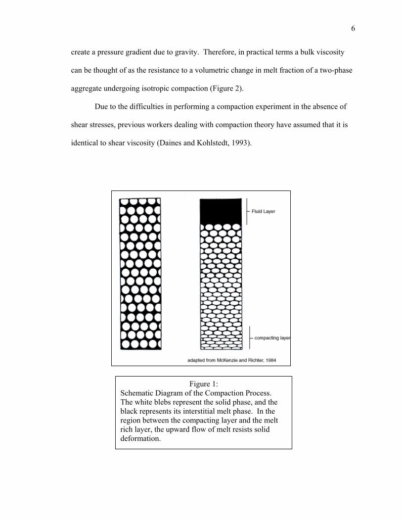
corresponding relative upward flow of melt (Figure 1). At the base of the column, where
solid velocities must diminish to zero, deformation of the solid grains occurs and a
compacting boundary layer is created. At the top of this layer, the upward velocity of
melt is sufficiently large to counteract the downward pressure of the matrix material.
This relationship holds above the boundary layer, where matrix material continues to
settle without deforming the solid grains. As this process continues, both the compacting
layer and the melt layer grow due to the continual loss of melt fraction below the
boundary layer and the corresponding increase in melt fraction above the boundary layer
(Figure 1). The governing equations of this model, given in their vector form are shown
below:
Γ=∇·ρfv=-∇·ρs(1-φ)V (1)
v-V=(-kφ/µφ)∇ Ρ (2)
(ζ+η/3)∇(∇·V)+η∇2V=(-µφ/kφ)(v-V)+(1-φ)(ρs-ρf)g z (3)
Equation 1 is a statement of conservation of mass, where Γ is the rate of mass transfer
from solid to fluid, ρf and ρs are the densities of the fluid and solid, V and v are the solid
and liquid velocities, and φ is the porosity. The second equation is a variation on Darcy’s
law where kφ is a melt fraction dependent permeability, µ is the fluid viscosity, and P is
the piezometric pressure. The final equation is a conservation of energy term where g is
acceleration due to gravity, z is a unit vector in the z direction and ζ and η are the bulk
and shear viscosities respectively.
The characteristic length scale of compaction, defined as the length over the
compaction rate decreases by a factor of e, is given as equation 4:
5
µηζδ )3/4( +
=K
c (4)
where δc is the compaction length, K is the permeability, ζ and η are the bulk and shear
viscosities, and µ is the fluid viscosity (McKenzie, 1984). Knowledge of these physical
properties allows for calculations of time and distance over which melt may migrate by
porous flow. However, while permeability can be estimated and shear viscosity and melt
viscosity are well understood and easily measured, bulk viscosity is an enigma for which
no measurements have been made.
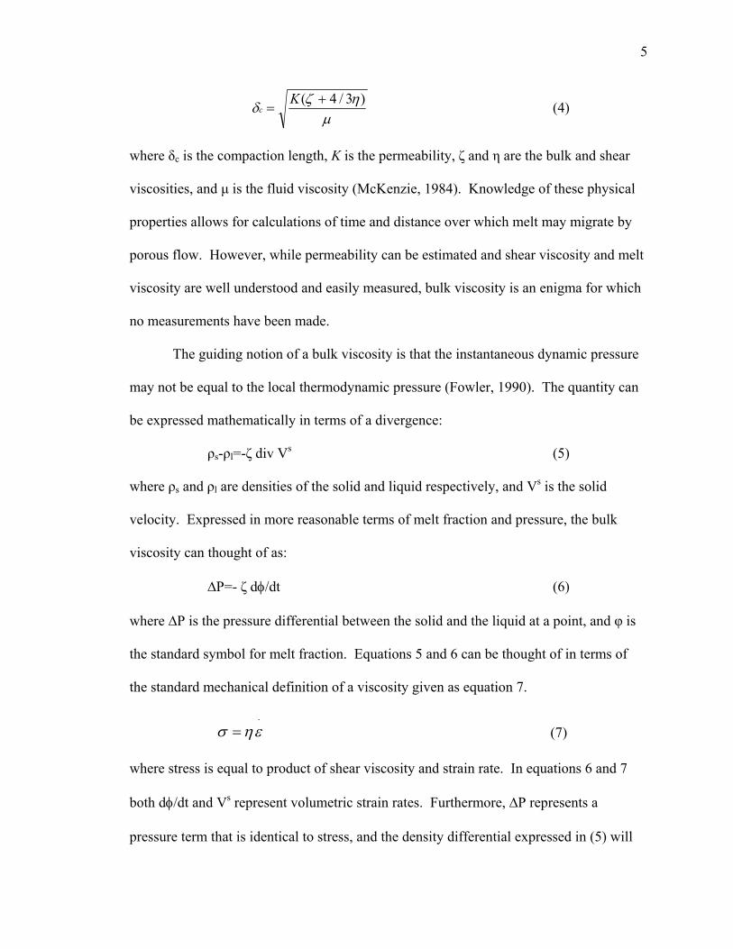
The guiding notion of a bulk viscosity is that the instantaneous dynamic pressure
may not be equal to the local thermodynamic pressure (Fowler, 1990). The quantity can
be expressed mathematically in terms of a divergence:
ρs-ρl=-ζ div Vs (5)
where ρs and ρl are densities of the solid and liquid respectively, and Vs is the solid
velocity. Expressed in more reasonable terms of melt fraction and pressure, the bulk
viscosity can thought of as:
∆P=- ζ dφ/dt (6)
where ∆P is the pressure differential between the solid and the liquid at a point, and φ is
the standard symbol for melt fraction. Equations 5 and 6 can be thought of in terms of
the standard mechanical definition of a viscosity given as equation 7.
⋅
= εησ (7)
where stress is equal to product of shear viscosity and strain rate. In equations 6 and 7
both dφ/dt and Vs represent volumetric strain rates. Furthermore, ∆P represents a
pressure term that is identical to stress, and the density differential expressed in (5) will
6
create a pressure gradient due to gravity. Therefore, in practical terms a bulk viscosity
can be thought of as the resistance to a volumetric change in melt fraction of a two-phase
aggregate undergoing isotropic compaction (Figure 2).
Due to the difficulties in performing a compaction experiment in the absence of
shear stresses, previous workers dealing with compaction theory have assumed that it is
identical to shear viscosity (Daines and Kohlstedt, 1993).
Figure 1: Schematic Diagram of the Compaction Process. The white blebs represent the solid phase, and the black represents its interstitial melt phase. In the region between the compacting layer and the melt rich layer, the upward flow of melt resists solid deformation.

7
3. Compaction: In the Special Case of an Inclusion
This difficulty in measuring values for the bulk viscosity in a two-phase aggregate
was addressed by (McKenzie and Holness, 2000). These authors present the theoretical
results of two-phase compaction in the presence of a rigid sphere. Their mathematical
experiments yield the solid velocity vectors that result from the interaction between the
compacting aggregate and the solid sphere. Their results demonstrate markedly different
flow behavior for an aggregate where the ratio of bulk viscosity to shear viscosity
(ζ/η=R) is large versus the case where it is small. In the case of a two-phase aggregate
Figure 2: Schematic Diagram showing the relationship between the bulk and shear viscosities in terms of diffusion pathways.

8
undergoing compaction where R is small, the aggregate will compact against the surface
of the sphere (Figure 3). This compaction will result in the loss of melt, which then flows
down the pressure gradient created by the sphere. Consequently, it will pool on both
sides of the inclusion forming a “pressure shadow” microstructure (Figures 5 and 7).
These predicted patterns of melt redistribution, for the cases where the compaction length
is much larger than inclusion size, are derived using the methods outlined in Appendix II.
In the opposite case, where R is large, the dominance of bulk viscosity will prevent
compaction, and the aggregate will tend to shear off the sphere with little or no change in
melt fraction (Figure 3). These predictions suggest a series of experiments that can be
used to both test the compaction theory and approximate values for R.
Figure 3 Matrix Particle Paths for various values of R. When this ratio is small, the matrix particle paths are almost unaffected by the sphere, while when the ratio is large they tend to deflect of the sphere’s surface.

9
Figure 4 The Divergence Field of the Solid Velocity Vector Field of the olivine+basalt system in the case where the ratio between bulk(ζ) and shear(η) viscosity is large. Note the very small amounts of melt accumulation in the regions of maximum compressive stress. The divergence in the region of minimum compressive stress is 600.
Figure 5 The Divergence Field of the Solid Velocity Vector Field of the olivine+basalt system in the case where the ratio between bulk(ζ) and shear(η) viscosity is small. Note the large amounts of melt accumulation in the regions of maximum compressive stress. The divergence in the region of minimum compressive stress is 1022
10
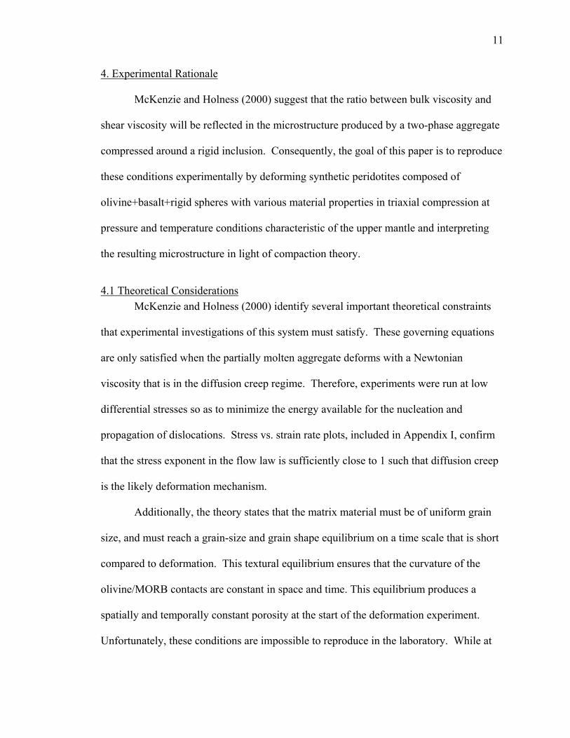
Figure 7 The Divergence Field of the Solid Velocity Vector Field of the Olivine+Basalt+FeS system in the case where the ratio between bulk(ζ) and shear(η) viscosity is small. Compare the predicted melt redistribution with that of Figure 5. The divergence in the region of minimum compressive stress is 0.06.
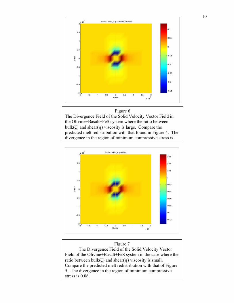
Figure 6 The Divergence Field of the Solid Velocity Vector Field in the Olivine+Basalt+FeS system where the ratio between bulk(ζ) and shear(η) viscosity is large. Compare the predicted melt redistribution with that found in Figure 4. The divergence in the region of minimum compressive stress is
11
4. Experimental Rationale
McKenzie and Holness (2000) suggest that the ratio between bulk viscosity and
shear viscosity will be reflected in the microstructure produced by a two-phase aggregate
compressed around a rigid inclusion. Consequently, the goal of this paper is to reproduce
these conditions experimentally by deforming synthetic peridotites composed of
olivine+basalt+rigid spheres with various material properties in triaxial compression at
pressure and temperature conditions characteristic of the upper mantle and interpreting
the resulting microstructure in light of compaction theory.
4.1 Theoretical Considerations McKenzie and Holness (2000) identify several important theoretical constraints
that experimental investigations of this system must satisfy. These governing equations
are only satisfied when the partially molten aggregate deforms with a Newtonian
viscosity that is in the diffusion creep regime. Therefore, experiments were run at low
differential stresses so as to minimize the energy available for the nucleation and
propagation of dislocations. Stress vs. strain rate plots, included in Appendix I, confirm
that the stress exponent in the flow law is sufficiently close to 1 such that diffusion creep
is the likely deformation mechanism.
Additionally, the theory states that the matrix material must be of uniform grain
size, and must reach a grain-size and grain shape equilibrium on a time scale that is short
compared to deformation. This textural equilibrium ensures that the curvature of the
olivine/MORB contacts are constant in space and time. This equilibrium produces a
spatially and temporally constant porosity at the start of the deformation experiment.
Unfortunately, these conditions are impossible to reproduce in the laboratory. While at

12
these high temperatures, T~1250 C, textural equilibrium is presumably reached on a short
time scale, a constant grain size is difficult to produce. In these experiments the average
grain size of the starting material is approximately 15 µm. Furthermore, after the
initiation of deformation and the subsequent fluid migration, a constant porosity is no
longer possible to maintain.
The deformation calculations are also made under the assumption that the sphere
is rigid (i.e., viscosity=∞) and stationary. Neither of these conditions are possible to
duplicate in the laboratory. Zirconia spheres (d=1mm) were chosen due to their hardness
and presumed non-reactivity, though no effort was made to ensure that they remain
stationary throughout the experiment.
The experimental temperature, at T~1250 C were chosen such that olivine is still
well under its solidus and will remain solid throughout the experiment. This temperature,
however, is sufficient to completely melt the MORB and create a fluid phase capable of
flowing in response to solid deformation.
A further assumption that is built into this theory, though not specifically stated, is
the ability of the melt phase to establish an interconnected network of channels in the
rock. The ability of the melt to establish these channels is controlled by the dihedral
angle, which is a ratio between the interfacial energies of the solid-solid and solid-liquid
interfaces. Experimental results indicate that dihedral angle in the olivine+basalt system
is sufficiently large such that the melt forms a completely interconnected network
(Daines and Richter, 1988; Riley, 1991).
13
4.2 Gravity Settling vs. Differential Stress and the Question of Finite Strain Compaction in magma chambers is believed to occur via gravity settling, where
density differences between the solid and the fluid create the pressure gradients that cause
the local reduction in melt fraction at the base of the magma chamber. This reduction in
melt fraction necessitates deformation of the solid because no pore spaces can open.
However, because it is not feasible to allow gravity driven compaction in the length scale
available in the laboratory, a differential stress is applied to the sample in order to initiate
compaction. In a deformation driven system, deformation of the solid grains creates the
pressure gradients that drive melt flow (Cooper, 1990).
A further question that must be addressed is the problem of finite strain. The
governing equations predict that a steady state melt distribution will occur. In
deformation driven systems, strain serves as a proxy for time. It is unclear how much
strain is necessary to achieve this state, or whether this steady state is possible to achieve
experimentally. This question is further complicated by the limitations of the
experimental design. The strain calculations presented in this thesis are measurements of
the bulk strain experienced by the entire sample. However, due to the heterogeneity of
the sample, and the no slip boundary imposed by friction at the piston/sample interface, it
is difficult to calculate the finite strain experienced by any point within the sample.
4.3 Bulk vs. Shear Viscosity In a system of known compaction length, the ratio of bulk to shear viscosity will
determine whether or not compaction occurs (McKenzie and Holness 2000).
Consequently, the principal goal of this paper is to approximate the ratio of bulk to shear
viscosity in the olivine+basalt system. Comparing the plots of melt density obtained
experimentally with the theoretical results obtained from the compaction theory yields an
14
approximation of the ratio between the bulk viscosity of the aggregate and the shear
viscosity of the solid phase. The methods of comparison between experiment and theory
are presented in Appendix III.
4.4 Why compaction length matters The compaction length of a two-phase aggregate can be thought of as a physical
parameter of the material (Holtzman et al., 2003). In natural melts, compaction lengths
vary from 1.4 mm for dry rhyolite to 1 km for basalt (Daines, 2000). In addition to the
central theme of approximating values for the two solid viscosities, it is instructive to
know the influence of this property on compacting behavior. Presumably, decreasing the
compaction length should reduce the quantity of melt that is free to migrate, hindering the
development of pressure shadows regardless of the ratio between bulk and shear viscosity
for those systems. Therefore, a secondary purpose of this paper is to investigate the role
of compaction length in the formation of pressure shadows.
The reference system for this thesis consists of a 95% San Carlos Olivine+5%
MORB aggregate. The compaction length for this system is large relative to sample size,
consequently there is an ample amount of melt migration. These olivine+basalt
experiments serve as baseline against which all other observations in this study are
compared.
The various properties that determine the compaction length can be manipulated
in the laboratory. Permeability, which is directly proportional to the square of the
compaction length, can be decreased with the addition of a third phase to the aggregate.
In the case of the experiments described in this thesis, small amounts of FeS were added.
Molten FeS is observed to reside at three and four grain triple junctions in the form of
15
small blebs. Consequently, the FeS acts as physical obstacle to melt flow and thus lowers
permeability. Permeability is an average and local property of the aggregate, which
begins to change at the onset of deformation.
Substituting plagioclase for olivine can decrease the viscosity of the solid phase,
which is also directly proportional to the compaction length. In this case, Beaver Bay
Anorthite (An=72) was used.
5. Experimental Design
Five sets of experiments were run in order to investigate melt migration around
rigid inclusions in the olivine+basalt system. The goals of these experiments were
threefold. First, these experiments set out to systematically vary the compaction length
by altering the material parameters contained in the compaction length equation.
Secondly, experiments were run to different strains so as to evaluate the dependence of
melt migration on strain. Values for the compaction length are calculated using
published values for µ, estimated values for k, and measured values for η. The method
used for calculating a compaction length in the absence of a bulk viscosity is outlined in
Table 1. The final purpose of these experiments is to deform rocks of identical
compositions to different strains to gauge the effect of strain on melt redistribution. The
important parameters of each experiment are summarized in Table 1. The five
experiments are as follows:
5.1. PI-950. Olivine+MORB+Inclusion.
This reference sample is composed of 95% Olivine+ 5% MORB+ 30 ZrO2
inclusions. This sample was deformed at P=300 MPa and T=1250 C to 20% strain in
16
pure shear with a constant load resulting in an initial differential stress of 100 MPa. The
compaction length is approximately 15 mm.
5.2. PI-951. Olivine+MORB+ Inclusion
A sample of identical composition to PI-950, but deformed to 250% strain in
simple shear. The compaction length is approximately 15 mm.
5.3. PI-984 Olivine+MORB+FeS+Inclusion
This sample was composed of 93% Olivine, 5% MORB, 2% FeS, and 30 ZrO2.
Small grains of FeS are observed to sit at 3 and 4-grain triple junctions. These grains
serve as a physical block to melt flow and thus decrease the permeability. Estimates of
permeability decrease follow those of (Holtzman et al., 2003). This sample was
deformed at P=300 MPa and T=1250 C to 20% strain in pure shear. Deformation
involved load stepping, which resulted in stresses ranging from 8.5 to 45 MPa. The
compaction length of this system is approximately 4.7 mm.
5.4. PI-988 Olivine+MORB+Inclusion
This sample has an identical composition to PI-950. The sample was deformed at
P=300 MPa and T=1250 C to 10% strain in pure shear with load steps resulting in
differential stresses ranging from 8.5 to 30 MPa. The compaction length for this system
is approximately 1.5 cm.

17
5.5. PI-997 Anorthite+MORB+Inclusion
This sample was composed of 94% Beaver Bay Anorthite, 6% MORB, and 30
ZrO2 inclusions. The sample was deformed at P=300 MPa and T=1200 C to 20% strain
in pure shear under load steps resulting in differential stresses between 8.5 and 25 MPa.
The lower viscosity of anorthite results in a smaller compaction length that is on the order
of the inclusion diameter. The compaction length of this system is approximately 8 mm.
6. Experimental Details
6.1 Drying and Cold Press Samples are first prepared by drying fine-grained (10-15 µm grain size) mineral
powders in a horizontal furnace at 1100 ˚C for approximately 12 hours within the
characteristic pO2 range that will not result in a phase change of the material. The dried
powders are then ground together in a mortar and pestle so as to ensure near complete
mechanical mixing. Next, the mixed powders are cold pressed into a cylindrical Fe
sample can with dimensions of 26 by 11 mm. Cold pressing involves pressing the sample
powders into the can with a hydraulic piston to a pressure of approximately 70 MPa. In
between layers of pressed powders, small (d=1mm) zirconia (ZrO2) spheres are placed in
the can. Three inclusions are placed in each vertical layer in a triangular orientation so as
to minimize interactions between the spheres. Each sample contained approximately 30
inclusions. This cold-press operation increases the density of the sample, reducing
porosity to approximately 7%.
18
6.2 Hot Press Cold pressing is followed by hydrostatic annealing, or hot press, wherein the
sample is brought to a pressure of 300 MPa and 1250 C for a period of three to five
hours. On either side of the sample, Al2O3 spacers are placed in order to make up any
length difference and maintain pressure within the sample jacket (Figure 9). These
spacers are surrounded by alumina (Al2O3 ) pistons. Finally, zirconia pistons are placed
at the outermost layer. A thermocouple is inserted through holes in the top two pistons
that allows temperature readings to be taken from as little as 5 mm away from the
sample. This entire assembly is encased in a formed Ni jacket, around which the
confining pressure is applied. This hot press further reduces porosity to between 1 and
2%, as verified by an Archimedes density calculation.
6.3 Deformation: Pure Shear Following hot press, the sample is ready for deformation. In these experiments,
the P/T conditions of deformation are identical to those of a hot press. This deformation
takes one of two forms, either deformation in triaxial compression or deformation in
simple shear. The sample assembly for a deformation experiment in triaxial compression
resembles that of a hot press, except that the sample can has a smaller diameter. In these
experiments, σ2 = σ3 = P. The maximum principal stress, σ1, can be varied with a servo-
controlled mechanical actuator. The operator may decide to constantly vary the load so
as to achieve a constant displacement rate or to maintain a constant load and allow strain
rate to vary with time. In either case, the geometry of the sample assembly prevents
deformation beyond approximately 30% strain.
19
6.4 Deformation: Simple Shear One experiment was also run under simple shear deformation. In this case,
pistons made of single crystal olivine are machined to a 45-degree angle. A thin sample
is polished into an ellipse and cut in two. The angled pistons and sample are all encased
within a nickel sleeve. Consequently, when the entire sample assembly is placed under
triaxial compression, the geometry of the pistons resolves the stress into the simple shear
experienced by the sample. It is important to note, however, that there is still a
component of normal stress applied to the sample, and thus this sample assembly is not
technically in perfect simple shear deformation.
After the desired strain has been reached, whether in triaxial compression or
simple shear, the sample is quenched. Quenching involves rapidly decreasing the sample
temperature under load so as to preserve microstructure and prevent any equilibration.
The unfortunate by-product of this process is the creation of cracks in the sample due to
different rates of thermal expansion between the different phases in the sample assembly.
6.5 Paterson Vessel Experimental deformation takes place in a Paterson-type gas medium pressure
apparatus. This device is capable of producing confining pressures as high as 500 MPa
using purified argon gas. Additionally, samples may be heated to temperatures as high as
1250 C using a ceramic furnace. This furnace is wrapped in three molybdenum wires
which provide heat through resistance. The voltage running to each wire can be
independently adjusted allowing for a constant temperature profile to be obtained over a
40 mm long region. Periodic calibrations ensure that this constant temperature profile
remains steady.

20
An actuator allows the operator to apply differential stresses to the sample. The
unique design of this apparatus features an internal load cell, which allows for very
precise measurements of the differential stresses that are applied to the sample. The
experimental setup permits for triaxial compression tests to strains as large as 30% strain
and simple shear tests to strains exceeding 500%. The deformation experiments can be
run at a constant displacement rate or a constant load depending on the goal of the
experiment.

21
Figure 10 Schematic of Paterson Vessel
Figure 8 Schematic Diagram of Simple Shear Deformation Assembly.
Figure 9 Schematic Diagram of Hot Press/ Pure Shear Deformation Assembly.

22
6.6 Sectioning and Polishing Following deformation, samples are sectioned in a high-speed diamond saw. Cuts
are made parallel to the shear direction in the orientation shown by Figure 11.
The samples are mechanically polished to 0.5 µm on diamond
lapping film and then polished to 0.25 µm using Syton
(colloidal silica). Syton polishing serves as both a mechanical
and chemical etch and acts to bring out relief at grain
boundaries. Following polishing, contrast between the MORB
and the olivine is further enhanced by etching the
samples with a mixture of dilute HCl- and HF-.
6.7 Optical Microscopy Digital Images of the sample surface are then taken in reflected light. Due to the
contrast between the black MORB and the grey olivine, higher resolution methods of
imaging are unnecessary. A typical reflected light image is shown in Figure 12.
Figure 12: PI-950:Inclusion 3 The white phase is the inclusion, the light grey the olivine, and the small black phase the MORB. Cracks and “pluckout” is also evident.
Figure 11: Orientation of Cuts with respect to the orientation of the principal stresses.

23
6.8 Binarization
The image is enhanced by digitally removing any cracks formed during
quenching and any holes left from grains “plucked-out” during polishing. The image is
then “binarized”. Binarization involves digitally removing the olivine such that only the
melt phase remains visible. By exploiting the characteristic shape of a melt pocket, this
procedure can be done by hand or using Adobe Photoshop. The resulting images
resemble Figure 13 below.
6.9 Contouring The final step of image analysis involves contouring the melt distribution. This
contouring is done using a program written with MATLAB. This integration algorithm
works by drawing a circle of a given radius around a point, calculating the volume of
melt within that circle and assigning that value to the point. These “smoothed” images
are then contoured. It is important to note that these contoured images are simply a
Figure 13: Binarized Image of Sample PI-950, inclusion 3
24
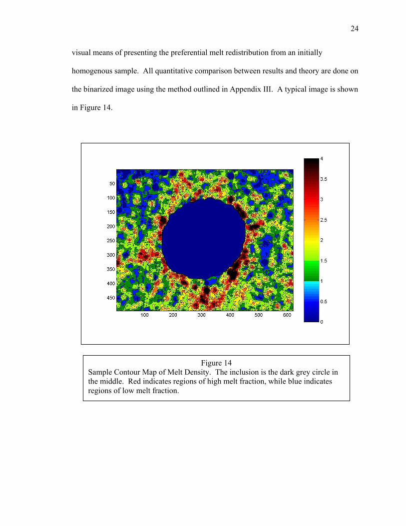
visual means of presenting the preferential melt redistribution from an initially
homogenous sample. All quantitative comparison between results and theory are done on
the binarized image using the method outlined in Appendix III. A typical image is shown
in Figure 14.
Figure 14 Sample Contour Map of Melt Density. The inclusion is the dark grey circle in the middle. Red indicates regions of high melt fraction, while blue indicates regions of low melt fraction.

25
7. Results:
Representative contour maps of melt density created using the methods
outlined above are presented for each of the conditions investigated. Additionally,
plots of melt fraction vs. distance are included for samples PI-950, PI-984, and PI-
988. These plots are obtained using the method outlined in Appendix (III). In all
cases, σ1 is vertical, save for the top to the right sense of simple shear enjoyed by
sample PI-951.
7.1 PI-950
σ1
Figure 15: Melt Density Contour Map of Sample PI-950

26
Note the “lobes” of high melt fraction in sample PI-950, with φ=0.1 to 0.15 on
either side of the sphere in reference sample PI-950 (Figure 15). Areas of extremely low
melt fraction, φ=0 to 0.025 formed immediately above and below the sample, ~0.1 mm
away from the sphere in each of the four quadrants. Two large areas of high melt fraction
are located top center and bottom center. The plot of melt fraction versus distance
supports these results (Figure 16). This plot is particularly sensitive to the regions of high
melt fraction above and below the inclusion. Consequently, these regions drown out the
smaller regions of melt accumulation on either side of the inclusion.
Figure 16 Plot of melt fraction vs. radial distance from inclusion in Sample PI-950. Note the sensitivity to the regions of high melt fraction above and below the inclusion.

27
7.2 PI-951
Sample PI-951 is the only sample in this thesis deformed in simple shear, to reach
a much higher strain. A large quantity of melt migrated, particularly into the region to
the southwest with melt fractions from 15.0% to 20.0% (Figure 17). Also, note the
elongated band-like structure of high melt concentration located above the inclusion
trending antithetic to the shear direction. This feature is morphologically similar to the
high permeability bands discussed in (Holtzman et al., 2003)). The mathematical
Figure 17 Melt density contour map of sample PI-951. The white ellipse in the center is the inclusion. Red indicates regions of high melt fraction, while blue indicates
regions of low melt fraction. Note the elongated linear-band of high melt concentration oriented above the inclusion antithetic to the shear direction.
28
difficulty of dealing with simple shear and the marked deformation enjoyed by the solid
sphere prevented analysis of these results in the context of compaction theory.
7.3 PI-984
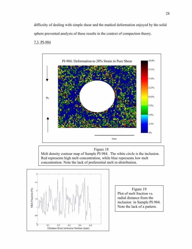
Figure 18 Melt density contour map of Sample PI-984. The white circle is the inclusion. Red represents high melt concentration, while blue represents low melt concentration. Note the lack of preferential melt re-distribution.
Figure 19 Plot of melt fraction vs. radial distance from the inclusion in Sample PI-984. Note the lack of a pattern.
σ1
29
Sample PI-984 was identical to sample PI-950 except for the inclusion of small
amounts of FeS in order to decrease the sample’s permeability. FeS does not appear in
this image because it is very soluble in HCl- and HF- and was dissolved during the
etching process. The melt distribution was much more homogenous than was observed
for sample PI-950 (Figure 18). For instance, the region of high melt fraction, φ=0.075 to
0.2, located above the inclusion is much less pronounced than in sample PI-950. Unlike
PI-950, these regions of high melt fraction are not well represented in the plot of melt
fraction vs. distance (Figure 19). Not only were the regions of melt accumulation an
order of magnitude smaller, this plot does show that little preferential redistribution of
melt has occurred during the experiment.
7.4 PI-988
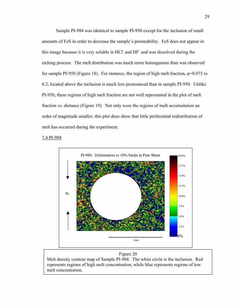
Figure 20 Melt density contour map of Sample PI-988. The white circle is the inclusion. Red represents regions of high melt concentration, while blue represents regions of low melt concentration.
σ1
30
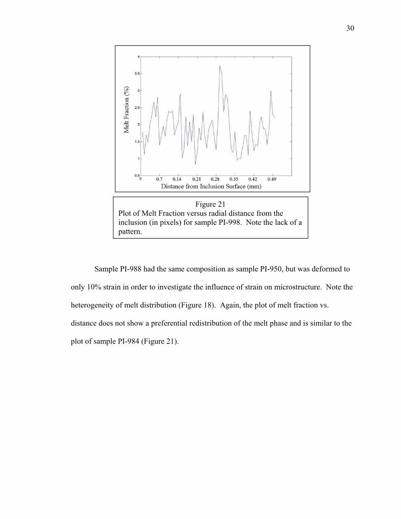
Sample PI-988 had the same composition as sample PI-950, but was deformed to
only 10% strain in order to investigate the influence of strain on microstructure. Note the
heterogeneity of melt distribution (Figure 18). Again, the plot of melt fraction vs.
distance does not show a preferential redistribution of the melt phase and is similar to the
plot of sample PI-984 (Figure 21).
Figure 21 Plot of Melt Fraction versus radial distance from the inclusion (in pixels) for sample PI-998. Note the lack of a pattern.

31
7.5 PI-997
The substitution of anorthite for olivine as the solid matrix material reduces the
compaction length of this system to the order of inclusion size. The initial melt fraction
was 0.06, compared to 0.05 for the other experiments. However, from the
photomicrograph above it is clear that the post-experiment melt fraction is much smaller.
This decrease in φ occurs because the MORB was under saturated in anorthite. The
resulting reaction precipitated clinopyroxene (Ginsberg, 2000). The melt pockets of this
melt+anorthite system do not reside in melt pockets of the same morphology as the
pockets in the olivine+basalt system. While the melt pockets of PI-997 do not appear to
1 mm
Figure 22: Reflected Light Photomicrograph of Sample PI-997. The small white blebs are the cryptocrystalline anorthite.

32
have adopted a preferential distribution around the inclusion, their scarcity prevents
quantitative analysis of their distribution (Figure 22). Future experiments in the
anorthite+basalt system must increase the initial basalt concentration to accommodate the
decrease in melt fraction during the experiment.
8. Discussion
The reference experiment PI-950 shows substantial movement of melt from the
region of high pressure to the region of low pressure following deformation to 20%
strain. This microstructure suggests that in olivine+basalt aggregates, the ratio of bulk to
shear viscosity is small. However, given these experimental data and this method of
interpretation, it is not possible to further constrain the ratio between bulk and shear
viscosity. This difficulty is due to the areas of extremely high melt fraction to the top and
bottom of the image that are not predicted by compaction theory. These features may be
due to the experimentally unsatisfied theoretical constraints that were discussed above.
They may also represent a second-order effect of two-phase flow that is not explained by
the compaction theory. In particular, compaction theory does not deal with the changes
in K, η, and ζ that must result from a change in φ. Therefore, the theory is only capable
of predicting dφ/dt at time zero. Compaction theory, in its present form, cannot fully
describe the evolution of φ as a function of time and space. It is worth noting that rings
of high melt fraction existed in many samples not described in this paper. While the
photomicrographs presented in this paper are necessarily two-dimensional, there is no
reason to assume that these structures are anything but symmetric about the axis of
maximum compressive stress. This argument is supported by the strong bilateral

33
symmetry exhibited by the microstructure developed in sample PI-950. Consequently,
the “caps” of high melt fraction exhibited by sample PI-950 would extrapolate to disks of
high melt fraction in three-dimensions, while the rings of high melt fraction seen in other
samples would extend to a sphere of high melt fraction approximately 0.5 mm away from
the surface of the sphere. In general, those samples that display the greatest quantity of
melt migration toward the regions of minimum compressive stress tend to exhibit this
feature the least. However, when the same system was deformed to only 10% strain
(sample PI-988), there was negligible melt migration. This observation suggests that the
role of strain, serving as a proxy for time in the case of deformation driven melt
migration, was the controlling factor in inhibiting melt migration. These observations
also support the assumption that the differential stress driven compaction discussed in
this paper can serve as an experimental analogue for the gravity driven compaction that is
often found in nature. However, there is no experimental evidence to suggest that 20%
strain is sufficient to produce a steady-state distribution, nor do these experiments
provide insight into whether or not this theoretical assumption is possible to satisfy
experimentally.
The importance of strain in melt migration is further elucidated by sample PI-951.
This sample exhibits the most melt redistribution, which is presumably related to the
much higher strains imposed on the sample. The linear band that is clearly evident in this
sample bears resemblance to the bands discussed by Holtzman et at. (2003). Given its
orientation relative to the inclusion, it is possible that the presence of the sphere
introduced a perturbation into the stress field and hence the melt fraction was amplified
by deformation in a manner similar to that described by (Stevenson, 1989). In this
34
analysis, a concentration of melt in the sample introduces a weakness in the sample due
to the lower viscosity of the fluid. Any subsequent strain experienced by the sample will
be preferentially accommodated in this weakened region. This situation creates a
positive feedback loop that increases the concentration of melt and therefore lowers the
viscosity and hence pressure of the region. Quantitative analysis of this sample in light of
compaction theory is convoluted by the complicated nature of deformation in simple
shear.
Sample PI-984, consisting of the olivine+basalt aggregate with the addition of
small quantities of FeS, also shows minimal melt migration. Presumably, this is due to
the decreased permeability of the aggregate due to the blocking of melt conduits by the
FeS grains. This sample most likely illustrates a relationship between the formation of
pressure shadows and the compaction length. The lack of preferential melt redistribution
suggests that the formation of pressure shadows is hindered when the compaction length
is on the order of inclusion size. Presumably, a small compaction length prevents
sufficient melt from flowing in response to the pressure gradient induced by the sphere.
The halo feature discussed earlier may also be present in this sample due to the
anomalously high melt fraction at the top of the image. Due to the negligible amount of
melt redistribution in this sample, presumably due to the small compaction length,
quantification of the ratio between bulk and shear viscosity is not possible with these
analytical methods. The difference in predicted redistribution is only one order of
magnitude between the plot of R>>1 and R <<1 in the olivine+basalt+FeS system. In the
case of the olivine+basalt system, the two predictions varied by as much as 20 orders of
magnitude. Consequently, considering the amount of melt redistribution developed in the
35
olivine+basalt experiments, it unlikely that a predicted difference as small as predicted
for the olivine+basalt+FeS system could be developed experimentally.
The qualitative observation that the ratio between bulk viscosity and shear
viscosity is low in partially molten olivine+basalt aggregates suggests that the current
method of applying compaction theory to natural processes is likely the correct one. The
relationship between bulk viscosity and shear viscosity described in equation (3)
indicates that a small ratio between the two viscosities renders the bulk viscosity
inconsequential. This argument also supports the method of computing compaction
lengths used in this paper and others of using a shear viscosity alone to describe the
viscosity of the solid phase.
In light of the controversy surrounding the importance of a bulk viscosity, it
would be interesting to know whether or not these experiments provide any evidence
regarding the necessity of including a bulk viscosity in the description of a compacting
two-phase aggregate. While these experiments suggest that the role of the bulk viscosity
is small in the olivine+basalt system, it is not reasonable to assume that these results
generalize to systems of different compaction lengths or material properties without a
more systematic investigation of various two-phase flows. Furthermore, experimental
investigations of compaction theory, in particular the interactions between a two-phase
flow and an inclusion, are in their infancy and the results of these experiments may be
complicated by this dearth of experience. Therefore, while these experiments produce
results that cannot, at present, be explained by the compaction theory, they should not be
interpreted as presenting a complication with the theory. When considering that the
compaction theory was developed in order to predict geodynamic phenomenon that occur
36
on the scale of meters and kilometers, it is exciting to find that it predicts the
development of millimeter and micron scale features as well as it does.
9. Conclusions/Future Direction
Given that compaction theory was designed in order to explain large-scale
phenomena, it is remarkable that it is also able to predict the development of micron-
scale deformation microstructures. Experimental results suggest that the bulk viscosity of
an olivine+basalt is small relative to the shear viscosity. However, experimental
observations deviated from theoretical predictions sufficiently that assigning a value to
the ratio of bulk to shear viscosity is not possible at this time. In particular, the
development of the regions of very high melt fraction above the inclusion, particularly in
sample PI-950, suggest that the theory may not completely explain the physics of two-
phase flow around a rigid inclusion undergoing triaxial compression. At present, I cannot
provide an explanation for these features. Developing techniques to quantify R in spite
of these features will be a central feature of future work with these experiments. Further
theoretical work may also be necessary to explain this phenomenon, as the theory does
not presently explain how changes in melt fraction effect η, ζ, and K. Due to these
considerations it is not possible to predict the final melt distribution created from
compaction around a sphere. At present, it is only possible to predict dφ/dt at time zero.
Though it is not yet reasonable to rule out experimental error as the cause of these effects.
Although many of these inclusions in sample PI-950 exhibited these pressure-shadow
microstructures, further experimental work is necessary to determine the reproducibility
of these structures.
37
Further work is also necessary in the anorthite-basalt system. In these
experiments, the initial melt concentration must be increased such that there is still
sufficient melt at the end of the experiment for useful measurements to be taken. It must
also be ascertained that the reactions between the anorthite and basalt do not influence or
impede the flow of melt.
As expected, the amount of strain a sample experienced does seem to correlate
with the amount of melt migration, suggesting that strain can indeed serve as a proxy for
time in these experiments. Furthermore, in these experiments the compaction length does
serve as an indicator of whether or not sufficient melt can be mobilized to form a pressure
shadow. In those samples where compaction length is on the order of inclusion size, the
samples exhibit little if any pressure shadow development. This result supports the
argument of (Holtzman et al. 2003 and others) that the compaction length is a material
property of the aggregate that can be used to understand its response to deformation.
Again, however, it is necessary to undertake a more systematic approach to varying the
compaction length of these partially molten aggregates.

Acknowledgements:
First off, thanks goes out to the Kohlstedt Research Group atthe University of Minnesota: David Kohlstedt, Mark Zimmerman (who was so kind as to run samples PI-950 and 951), Take Hiraga, Ben Holtzman, Sash Majumder, and Justin Hustoff. I feel distinctly privileged to have had the opportunity to work in your lab. I wish I could give y’all back all the time you spent helping this prodigal undergrad. Special thanks to Dan McKenzie for his gracious help with the mathematics of compaction. Additionally, special thanks to Reid Cooper for suggesting the zirconia spheres. I would also like to thank Dave Bice for his help at the Carleton end. Furthermore, I would also like to thank the NSF-REU program at the U of M for funding my summer work. This thesis also benefited from conversations with folks at AGU and my bi-weekly trips to the U of M., there I would like to thank the Bernstein foundation for their financial support.

39
Appendix I: Rheological Data for selected samples:
Rheological Data
y = 0.9665x - 6.6073y = 0.5089x - 5.9271
y = 0.419x - 5.2286
-5.9
-5.7
-5.5
-5.3
-5.1
-4.9
-4.7
-4.50.8 0.9 1 1.1 1.2 1.3 1.4 1.5 1.6 1.7 1.8
log (σ)
log ε
PI-984
PI-988
PI-997
Linear (PI-988)
Linear (PI-997)
Appendix II: Predictions of melt redistribution from Compaction Theory McKenzie and Holness (2000) provides expressions for the solid velocity
vector field. Because no pore space can open in the aggregate, the rate of change of
porosity (identical to melt fraction in a partially molten aggregate) in a partially molten
aggregate where compaction length is much larger than inclusion size can be found from
the divergence of this vector field. The necessary expression is given below:
)2
1cos3()32(3
152 23
3 −+
−=⋅∇= − θββµµφ
φφrDa
kkdtd V
40
where µ is the viscosity of the melt phase, D is the amount of shortening, a is a grain size
term, θ is the angle between the point in question and the direction of uniaxial shortening.
kφ is the melt fraction dependent permeability, and )
34(
1
+=
ηζ
β .
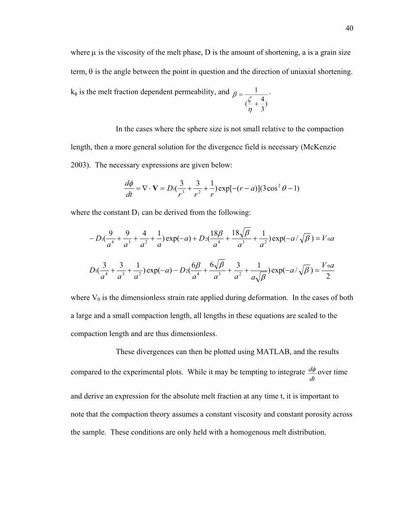
In the cases where the sphere size is not small relative to the compaction
length, then a more general solution for the divergence field is necessary (McKenzie
2003). The necessary expressions are given below:
)1cos3)]((exp[)133( 2231 −−−++=⋅∇= θφ ar
rrrD
dtd V
where the constant D1 can be derived from the following:
aVaaaa
Daaaaa
D 023422341 )/exp()11818()exp()1499( =−+++−+++− βββ
2)/exp()1366()exp()133( 0
23422341aVa
aaaaDa
aaaD =−+++−−++ β
βββ
where V0 is the dimensionless strain rate applied during deformation. In the cases of both
a large and a small compaction length, all lengths in these equations are scaled to the
compaction length and are thus dimensionless.
These divergences can then be plotted using MATLAB, and the results
compared to the experimental plots. While it may be tempting to integrate dtdφ over time
and derive an expression for the absolute melt fraction at any time t, it is important to
note that the compaction theory assumes a constant viscosity and constant porosity across
the sample. These conditions are only held with a homogenous melt distribution.

41
Consequently, the theory breaks down and cannot be used to predict final melt
distributions (Dan McKenzie, personal communication).
Appendix III: Techniques of Numerical Image Analysis
Comparisons between the observed melt distributions and the melt
distributions predicted by compaction theory require a more systematic approach than the
contoured images. The simplest way to do this is to exploit the orthogonality of two
spherical harmonics (Dan McKenzie, personal communication). Orthogonality implies
that when two spherical harmonics are multiplied together, and an integral is taken over
that spherical surface the result is zero. This operation is a higher dimension analogue to
finding that the dot product of two vectors is zero. Consequently, when the melt fraction
is multiplied by the spherical harmonic that describes the predicted melt fraction, and an
integral is taken over this surface, a plot of this integral vs. radius will give a quantitative
picture of how melt fraction changes spatially. The integral is given below:
θθθθπ
d∫+
Φ2
0
sin4
12cos3)(
where Ф is the melt fraction and θ is the angle between the point in question and the
uniaxial shortening direction. The term 4
12cos3 +θ is a spherical harmonic of degree 2
and order 0, and is identical to the harmonic presented in the case of uniaxial compaction
onto the xy plane found in (McKenzie and Holness, 2000). The sin θ term takes care of
the fact that this is an integral over a spherical surface rather than a circle, and assumes
that the melt fraction is axisymmetric about the shortening direction.
42
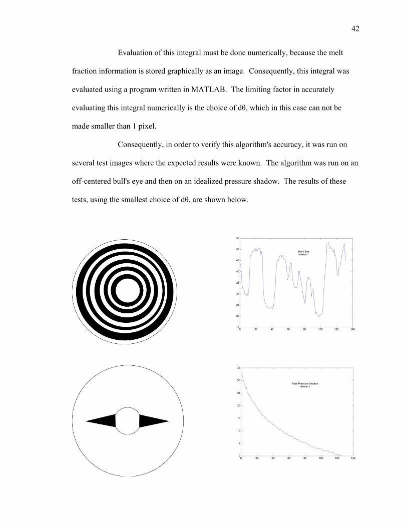
Evaluation of this integral must be done numerically, because the melt
fraction information is stored graphically as an image. Consequently, this integral was
evaluated using a program written in MATLAB. The limiting factor in accurately
evaluating this integral numerically is the choice of dθ, which in this case can not be
made smaller than 1 pixel.
Consequently, in order to verify this algorithm's accuracy, it was run on
several test images where the expected results were known. The algorithm was run on an
off-centered bull's eye and then on an idealized pressure shadow. The results of these
tests, using the smallest choice of dθ, are shown below.

43
In these plots, the x-axis shows the distance from the sphere in pixels, and
the y-axis shows the "melt fraction" of these images at that particular radius. These
results support the use of this algorithm on the experimental data. The MATLAB script
used to calculate this integral is given below.
%This simple MATLAB script reads information from a black and white .jpg image %and computes the spherical harmonic coefficients that best fit the melt variation % %Remaining Questions: %Am I measuring the angle, theta, correctly? %Is the method of integration accurate enough? %Is it appropriate to fit a curve to the data? % % %Last updated 2-13-2003 % function meltdistribution(infile); imagein=double(imread(infile,'jpg')); disp('This all assumes that the image is 640 by 480.') initialy=input('What is the x-coordinate of the sphere center?'); x2=input('What is the y-coordinate of the sphere center?'); initialx=543-x2; %must be changed to image height spheresize=input('What is the radius of the sphere?'); radius=input('To what radius would you like to compute?'); dtheta=input('What is dtheta, in degrees?'); angle=linspace(0,(2*pi),360); a=0; xcoord=1:1:360; ycoord=1:1:360; melt=0; area=0; meltfraction=0; interval=360/dtheta; c=1; d=dtheta; counter=1; counter2=1; SHmeltfraction=1:1:interval; harmoniccoefficient=0; radialiter=0; radii=radius-spheresize; Sharmonicvar=1:1:radii; for radialiter=spheresize:radius for e=1:interval for a=c:d; xcoord(a)=round((initialx)+(radialiter*cos(angle(a)))); ycoord(a)=round((initialy)+(radialiter*sin(angle(a)))); e=imagein(xcoord(a),ycoord(a)); if e<50 melt=melt+1;

44
end area=area+1; a=a+1; counter=counter+1; end meltfraction=melt/area; theta=((pi/4)-((dtheta*pi)/180)*(e)); %here is one of the grey areas SHmeltfraction(counter)=meltfraction*.25*(3*(cos(2*theta))+1)*sin(theta); harmoniccoefficient=harmoniccoefficient+SHmeltfraction(counter); melt=0; area=0; c=c+dtheta; d=d+dtheta; e=e+1; end a=0; c=1; d=dtheta; Sharmonicvar(counter2)=harmoniccoefficient; radialiter=radialiter+1; counter2=counter2+1; harmoniccoefficient=0; counter=1; end figure plot(Sharmonicvar) % % %Curve Fitting Routine % % % figure n=2; x=1:1:(counter2-1); p=polyfit(x,Sharmonicvar,n); y=polyval(p,x); plot(x,y,'--'); title('Curve Fitted Spherical Harmonic Variation')
Appendix IV: Some Notes on Scaling:
There are several important variables that are important to consider when
experimentally deforming mantle rocks. For example, the Paterson vessel is capable of
producing confining pressures up to 500 MPa. This pressure, however, does not simulate
45
mantle pressures, save extremely shallow mantle immediately below oceanic crust.
Furthermore, grain size in the laboratory is in the range of 10-15 µm, while grain sizes in
nature are on the order of tens of mm and greater. Geologically significant strain rates
are also on the order of 10-14 to 10-16, while feasibility constraints in the laboratory limit
strain rates to the neighborhood of 10-4 to 10-5. Consequently, it is important to consider
the factors involved in the scaling of geologic deformation processes to those possible in
the laboratory. While the precise nature of these relationships is still the subject of
considerable debate, the current thinking involves the dimensionless number:
2
lD
.ε
where .ε is the strain rate, D is the diffusivity of the material (constant regardless of
setting) and l is a length scale which is often taken as a grain size term. Consequently,
comparison between this dimensionless number (which currently has no name) for
laboratory conditions and geologic conditions will give some indication of what variables
must be changed to simulate geologic processes in the laboratory. Consequently, in the
lab grain sizes are several orders of magnitude smaller than in nature, and strain rates are
many orders of magnitude faster. Furthermore, the effect of confining pressure on the
rheology of mantle rocks is small. The relationship between stress and strain is typically
given by a flow law, which takes the form:
+−
=
RTpVE
hb
GA aa
mn
exp. σε .

46
where A is a pre-exponential factor, G is the shear modulus, h is the grain size, and b the
lattice spacing (Turcotte and Schubert, 2002). Values for m and n depend on deformation
mechanism. Ea is the activation energy, Va the activation volume, p the pressure, R the
ideal gas constant, and T the temperature in Kelvin. Consequently, it is clear that the
effect of pressure is tied to activation volume and the value of the exponential is also
dependant on activation energy and temperature.
Quantity(Karato and Wu, 1993) Diffusion Creep Dislocation Creep
Preexponential Factor, A 8.7 E 15 s-1 3.5 E 22 s-1
Stress Exponent, n 1 3.5
Grain Size Exponent, m 2.5 0
Activation Energy,Ea 300 kJ mol -1 540 kJ mol -1
Activation Volume, Va 6E-6 m3 mol –1 2E-5 m3 mol –1
G 80 GPa 80 GPa
b 0.5 nm 0.5nm
However, given these values for a dry upper mantle, the effect of pressure is negligible
because the activation volume of olivine is so small, and is thus dwarfed by the activation
energy and temperature in determining the value for the exponential. Furthermore, the
confining pressure that can be applied to a sample is also limited by technology. At
present, gas-medium apparatuses are limited to approximately 500 MPa due to the
inherent risk in putting a gas under greater pressures.

47
Table 1: Values for compaction length are calculated using a variation of equation 4,
where the measured solid viscosity terms from the experiments replace the bulk/shear viscosity terms. Values for permeability (k) are calculated using the
relationship: bdk
n 2φ= where φ is the melt fraction, n is constant, d is the grain diameter,
and b is a geometric constant (Turcotte and Schubert, 2002). N is given a value of 2 and b is given as 103 in the olivine+MORB samples and 104 in the olivine+MORB+FeS samples following (Holtzman et al., 2003). Values for η are calculated from the rheological data given in Appendix I. Values for µ are taken from the literature(Urbain et al., 1982).
Sample Composition φ P/T Conditions
ε
%
k (m2)
η (Pa·s)
µ (Pa·s)
Compaction Length (m)
Melt Redistribution
PI-950
Olivine+MORB+ Inclusions
.05
300MPA 1250 C
20
5.6 x 10⁻¹⁶
4.0 x 10¹²
10
1.5x10⁻²
Yes
PI-951
Olivine+MORB+ Inclusions
.05
300MPA 1250 C
250
5.6 x 10⁻¹⁶
4.0 x 10¹²
10
1.5x10⁻²
Yes
PI-984
Olivine+MORB+ FeS+Inclusion
.05
300MPA 1250 C
20
5.6 x 10⁻¹⁷
4.0 x 10¹²
10
4.7x10⁻³
No
PI-988
Olivine+MORB+ Inclusions
.05
300MPA 1250 C
10
5.6 x 10⁻¹⁶
4.0 x 10¹²
10
1.5x10⁻²
No
PI-997
Anorthite+MORB+Inclusions
.06
300MPA 1200 C
20
5.6 x 10⁻¹⁶
8.0 x 10¹¹
10?
8.0x10⁻³
Probably Not

48
Aharonov, E. W., J. A.; Kelemen, P. B.; Spiegelman, M., 1995, Channeling instability of
upwelling melt in the mantle, v. 100, no. 10, p. 20,433-20,450. Batchelor, G. K., 1967, An introduction to fluid dynamics: Cambridge, Cambridge
University Press, 615 p. Bercovici, D., Ricard, Y., and Schubert, G., 2001a, A two-phase model for comaction
and damage 3. Applications to shear localization and plate boundary formation: Journal of Geophysical Research, v. 106, no. B5, p. 8925-8939.
-, 2001b, A two-phase model for compaction and damage 1.General Theory: Journal of Geophysical Research, v. 106, no. B5, p. 8887-8906.
Cooper, R. F., 1990, Differential Stress Induced Melt Migration: An Experimental Approach: Journal of Geophysical Research, v. 95, no. B5, p. 6979-6992.
Daines, M., 2000, Migration of Melt, in Stix, J., ed., Encyclopedia of Volcanoes: San Diego, Academic Press, p. 69-88.
Daines, M., and Kohlstedt, D. L., 1993, A Laboratory Study of Melt Migration: Philosophical Transaction of the Royal Society of London: Physical Sciences and Engineering, v. 342, no. 1663, p. 43-52.
Daines, M., and Richter, F. M., 1988, An experimental method for directly determing the interconnectivity of melt in a partially molten system: Geophysical Research Letters, v. 15, p. 1459-1462.
Fowler, A. C., 1985, A mathematical model of magma transport in the asthenosphere, v. 33, no. 1, p. 63-96.
-, 1990, A compaction model for melt transport in the Earth's asthenosphere. Part I: the basic model, in Ryan, M. P., ed., Magma Transport and Storage: New York, John Wiley and Sons.
Ginsberg, S. B., 2000, Deformation of Diabase with Application to the Tectonics of Earth and Venus [PhD thesis]: University of Minnesota.
Holtzman, B. K., Groebner, N. J., Zimmerman, M. E., Ginsberg, S. B., and Kohlstedt, D. L., 2003, Deformation-driven melt segregation in partially molten rocks: G3, v. in press.
Karato, S.-i., and Wu, P., 1993, Rheology of the Upper Mantle: A Synthesis: Science, v. 260, no. 5109, p. 771-778.
Kelemen, P. B., Hirth, G., Shimizu, N., Spiegleman, M., and Dick, H. J. B., 1997, A review of melt migration processes in the adiabatically upwelling mentle beneath oceanic spreading ridges: Philosophical Transaction of the Royal Society of London, v. 355, p. 283-318.
McKenzie, D., 1984, The Generation and Compaction of Partially Molten Rock: Journal of Petrology, v. 25, no. 3, p. 713-765.
-, 1989, Some remarks on the movement of small melt fractions in the mantle: Earth and Planetary Science Letters, v. 95, no. 1-2, p. 53-72.
McKenzie, D., and Holness, M., 2000, Local deformatin in compacting flows:development of pressure shadows: Earth and Planetary Science Letter, v. 180, p. 169-184.
Ribe, N. M., 1985, The generation and composition of partial melts in the Earth's mantle: Earth and Planetary Science Letter, v. 73, p. 361-376.

49
Richardson, C. N. L., J. R.; McKenzie, D., 1996, Melt conduits in a viscous porous matrix, v. 101, no. 9, p. 20,423-20,432.
Richter, F. M., and McKenzie, D., 1984, Dynamical Models for Melt Segregation from a Deformable Matrix: Geology, v. 92, p. 729-740.
Riley, G. N., Jr.; Kohlstedt, D. L., 1991, Kinetics of melt migration in upper mantle-type rocks, v. 105, no. 4, p. 500-521.
Riley, G. N., and Kohlstedt, D. L., 1990, Melt Migration in a Silicate Liquid0Olivine System: An Experimental Test of Compaction Theory: Geophysical Research Letters, v. 17, no. 12, p. 2101-2104.
Scott, D. R., and Stevenson, D. J., 1986, Magma Ascent by Porous Flow: Journal of Geophysical Research, v. 91, no. B9, p. 9283-9296.
Scott, D. R. S., David J., 1989, A self-consistent model of melting, magma migration, and buoyancy-driven circulation beneath mid-ocean ridges, v. 94, no. 3, p. 2973-2988.
Spiegelman, M., and McKenzie, D., 1987, Simple 2-D models for melt extraction at mid-ocean ridges and island arcs: Earth and Planetary Science Letters, v. 83, no. 1-4, p. 137-152.
Spiegelman, M. K., Patricia M., 1992, The requirements for chemical disequilibrium during magma migration: Earth and Planetary Science Letter, v. 109, no. 3-4, p. 611-620.
Stevenson, D. J., 1989, Spontaneous small-scale melt segregation in partial melts undergoing deformation: Geophysical Research Letters, v. 16, no. 9, p. 1067-1070.
Turcotte, D., and Schubert, G., 2002, Geodynamics: Cambridge, Cambridge University Press, 456 p.
Urbain, G., Bottinga, Y., and Richet, P., 1982, Viscosity of liquid silica, silicates and alumino-silicates: Geochemica et Cosmochimica Acta, v. 46, p. 1061-1072.