an experimental study of electromagnetic lorentz force and
TRANSCRIPT

Calhoun: The NPS Institutional Archive
Theses and Dissertations Thesis Collection
2009-12
An experimental study of electromagnetic Lorentz
Force and rail recoil
Putnam, Michael, J.
Monterey, California. Naval Postgraduate School
http://hdl.handle.net/10945/4348
brought to you by COREView metadata, citation and similar papers at core.ac.uk
provided by Calhoun, Institutional Archive of the Naval Postgraduate School

NAVAL
POSTGRADUATE SCHOOL
MONTEREY, CALIFORNIA
THESIS
Approved for public release; distribution is unlimited
AN EXPERIMENTAL STUDY OF ELECTROMAGNETIC LORENTZ FORCE AND RAIL RECOIL
by
Michael J. Putnam
December 2009
Thesis Advisor: William B. Maier II Co-Advisor: Peter P. Crooker

THIS PAGE INTENTIONALLY LEFT BLANK

i
REPORT DOCUMENTATION PAGE Form Approved OMB No. 0704-0188Public reporting burden for this collection of information is estimated to average 1 hour per response, including the time for reviewing instruction, searching existing data sources, gathering and maintaining the data needed, and completing and reviewing the collection of information. Send comments regarding this burden estimate or any other aspect of this collection of information, including suggestions for reducing this burden, to Washington headquarters Services, Directorate for Information Operations and Reports, 1215 Jefferson Davis Highway, Suite 1204, Arlington, VA 22202-4302, and to the Office of Management and Budget, Paperwork Reduction Project (0704-0188) Washington DC 20503. 1. AGENCY USE ONLY (Leave blank)
2. REPORT DATE December 2009
3. REPORT TYPE AND DATES COVERED Master’s Thesis
4. TITLE AND SUBTITLE An Experimental Study of Electromagnetic Lorentz Force and Rail Recoil 6. AUTHOR(S) Michael J. Putnam
5. FUNDING NUMBERS
7. PERFORMING ORGANIZATION NAME(S) AND ADDRESS(ES) Naval Postgraduate School Monterey, CA 93943-5000
8. PERFORMING ORGANIZATION REPORT NUMBER
9. SPONSORING /MONITORING AGENCY NAME(S) AND ADDRESS(ES)
N/A
10. SPONSORING/MONITORING AGENCY REPORT NUMBER
11. SUPPLEMENTARY NOTES The views expressed in this thesis are those of the author and do not reflect the official policy or position of the Department of Defense or the U.S. Government. 12a. DISTRIBUTION / AVAILABILITY STATEMENT Approved for public release; distribution is unlimited
12b. DISTRIBUTION CODE
13. ABSTRACT (maximum 200 words) Understanding whether recoil forces are seated in the rails of any electromagnetic launch technology, including railguns, is critical for efficient development and design. Several theoretical and experimental researchers have produced multiple published papers characterizing rail recoil. These papers are not definitive and often conflict. An experiment has been developed that allows for the simultaneous measurements of the quasi-static Lorentz force on the armature and rail recoil. The primary challenge in quantifying these forces is removing the mechanical coupling required to construct the necessary circuit while maintaining electrical connectivity. Liquid metal Ga/In eutectic was used to conduct electricity while mechanically decoupling the rails from the rest of the circuit. Force measurements show that the force on the armature increases as the square of the current while the indicated reaction force on the rails is an artifact of the experiment. These recoil forces measured <1% of the force on the armature. We conclude that the recoil, or corresponding equal and opposite reaction force to the force on the armature, is not seated in the rails.
15. NUMBER OF PAGES
71
14. SUBJECT TERMS Railgun, Railgun recoil, Lorentz force, eutectic
16. PRICE CODE
17. SECURITY CLASSIFICATION OF REPORT
Unclassified
18. SECURITY CLASSIFICATION OF THIS PAGE
Unclassified
19. SECURITY CLASSIFICATION OF ABSTRACT
Unclassified
20. LIMITATION OF ABSTRACT
UU NSN 7540-01-280-5500 Standard Form 298 (Rev. 2-89) Prescribed by ANSI Std. 239-18

ii
THIS PAGE INTENTIONALLY LEFT BLANK
iii
Approved for public release; distribution is unlimited
AN EXPERIMENTAL STUDY OF ELECTROMAGNETIC LORENTZ FORCE AND RAIL RECOIL
Michael J. Putnam
Lieutenant, United States Navy B.S., University of North Florida, 2003
Submitted in partial fulfillment of the requirements for the degree of
MASTER OF SCIENCE IN APPLIED PHYSICS
from the
NAVAL POSTGRADUATE SCHOOL December 2009
Author: Michael J. Putnam
Approved by: William B. Maier II Thesis Advisor
Peter P. Crooker Co-Advisor
Andres Larraza Chairman, Department of Physics

iv
THIS PAGE INTENTIONALLY LEFT BLANK

v
ABSTRACT
Understanding whether recoil forces are seated in the
rails of any electromagnetic launch technology, including
railguns, is critical for efficient development and design.
Several theoretical and experimental researchers have
produced multiple published papers characterizing rail
recoil. These papers are not definitive and often
conflict. An experiment has been developed that allows for
the simultaneous measurements of the quasi-static Lorentz
force on the armature and rail recoil. The primary
challenge in quantifying these forces is in removing the
mechanical coupling required to construct the necessary
circuit while maintaining electrical connectivity. Liquid
metal Ga/In eutectic was used to conduct electricity while
mechanically decoupling the rails from the rest of the
circuit. Force measurements show that the force on the
armature increases as the square of the current while the
indicated reaction force on the rails is an artifact of the
experiment. These recoil forces measured <1% of the force
on the armature. We conclude that the recoil, or
corresponding equal and opposite reaction force to the
force on the armature, is not seated in the rails.

vi
THIS PAGE INTENTIONALLY LEFT BLANK

vii
TABLE OF CONTENTS
I. INTRODUCTION ............................................1 A. MOTIVATION .........................................1 B. OBJECTIVE ..........................................2 C. BACKGROUND .........................................2
II. EXPERIMENTAL SETUP ......................................5 A. PREVIOUS RESEARCH ..................................5 B. COMPONENTS .........................................5
1. The Rails .....................................5 2. Pendulum Suspension ...........................6 3. Armature and Eutectic .........................7 4. Power Supply, Switching, and Resistance .......9 5. Splitting the Rails ..........................11 6. Instrumentation ..............................13
III. EXPERIMENTAL PROCEDURE .................................17 A. SCOPE .............................................17 B. RECORDING LORENTZ FORCE AND RECOIL ................17 C. SPLITTING THE RAILS ...............................18
IV. EXPERIMENTAL RESULTS ...................................19 A. SIMULTANEOUS LORENTZ AND RECOIL FORCES ............19 B. SPLIT RAIL MEASUREMENTS ...........................25
1. Armature Lorentz Force and Recoil on the Muzzle Half Rail .............................25
2. Forces Between the Rail Halves ...............27 C. SUMMARY ...........................................29
APPENDIX ....................................................31 1. LORENTZ FORCE AND RECOIL ..........................31 2. SPLIT RAILS—LORENTZ FORCE AND MUZZLE HALF RECOIL ..37 3. SPLIT RAILS—OPPOSING FORCES ON EACH RAIL HALF .....45
LIST OF REFERENCES ..........................................49
INITIAL DISTRIBUTION LIST ...................................53

viii
THIS PAGE INTENTIONALLY LEFT BLANK
ix
LIST OF FIGURES
Figure 1. Schematic illustration of railgun operation [From 29]........................................3
Figure 2. Copper rails and armature........................5 Figure 3. Pendulum suspension system-not to scale, [From
30]..............................................6 Figure 4. Rail/armature interface..........................8 Figure 5. 3D translation system............................8 Figure 6. Schematic of model railgun circuit (not to
scale)...........................................9 Figure 7. Graphite plate resistor.........................10 Figure 8. Meidensha 50 kA vacuum interrupter and breech
electrical connection...........................11 Figure 9. Split rails.....................................12 Figure 10. Rail tabs submerged in eutectic.................12 Figure 11. LC305-25 load cell..............................13 Figure 12. Ammeter shunt with leads routed to USB-6211 DAQ.14 Figure 13. NI USB-6211 DAQ connected to laptop.............15 Figure 14. SR560 low noise preamplifiers connected to
USB-6211........................................16 Figure 15. Instrumentation flow chart......................16 Figure 16. Lorentz force armature load cell (a), recoil
force load cell (b).............................17 Figure 17. Load cells set up for split rails...............18 Figure 18. Armature Lorentz force and rail recoil force
for 1.2 kA pulse................................21 Figure 19. Armature Lorentz forces and rail recoil forces
for 1.2 kA and 2.5 kA pulses....................22 Figure 20. Armature Lorentz force and steady state rail
recoil vs current...............................24 Figure 21. Split rails-armature Lorentz force and rail
recoil force for 1.8 kA pulse...................26 Figure 22. Split rail—Opposing rail forces for 2 kA
current pulse...................................28 Figure 23. Armature Lorentz force and rail recoil force
for 1.2 kA pulse...............................31 Figure 24. Armature Lorentz force and rail recoil force
for 1.5 kA pulse...............................32 Figure 25. Armature Lorentz force and rail recoil force
for 1.7 kA pulse...............................33 Figure 26. Armature Lorentz force and rail recoil force
for 1.8 kA pulse...............................34 Figure 27. Armature Lorentz force and rail recoil force
for 2.6 kA pulse...............................35
x
Figure 28. Armature Lorentz force and rail recoil force for 2.7 kA pulse...............................36
Figure 29. Split rail—armature Lorentz force and recoil force for 0.7 kA pulse..........................37
Figure 30. Split rail—armature Lorentz force and recoil force for 1.2 kA pulse..........................38
Figure 31. Split rail—armature Lorentz force and recoil force for 1.3 kA pulse..........................39
Figure 32. Split rail—armature Lorentz force and recoil force for 1.3 kA pulse..........................40
Figure 33. Split rail—armature Lorentz force and recoil force for 1.4 kA pulse..........................41
Figure 34. Split rail—armature Lorentz force and recoil force for 1.4 kA pulse..........................42
Figure 35. Split rail—armature Lorentz force and recoil force for 1.9 kA pulse..........................43
Figure 36. Split rail—armature Lorentz force and recoil force for 2 kA pulse............................44
Figure 37. Split rail—opposing rail forces for 1.1 kA current pulse...................................45
Figure 38. Split rail—opposing rail forces for 1.2 kA current pulse...................................46
Figure 39. Split rail—opposing rail forces for 1.4 kA current pulse...................................47

xi
LIST OF TABLES
Table 1. Peak rail recoil force measurements.............23 Table 2. Steady-state rail recoil forces.................23

xii
THIS PAGE INTENTIONALLY LEFT BLANK

xiii
ACKNOWLEDGMENTS
I would like to thank Professor Bill Maier for his
guidance and endless support. This project was made
possible by his previous work with Matthew Schroeder.
I would like to thank Professor Pete Crooker for his
tremendous teaching ability. Without his assistance, I
would still be toiling away and this research project would
not have been the same.
I must recognize Don Snyder and Gene Morris who are
the technicians behind the scenes that make everything
happen in the NPS railgun lab. Their help was instrumental
in every phase of this research project.
This work was supported by the Office of Naval
Research and their Electromagnetic Railgun Program.

xiv
THIS PAGE INTENTIONALLY LEFT BLANK

1
I. INTRODUCTION
A. MOTIVATION
For over 200 years, electromagnetic forces have been
extensively researched. During 1802, Gian Domenico
Romagnosi noticed that a magnetic needle deflected when
electricity from a crude battery was turned on and off [1].
Less than 20 years later, Hans Christian Oersted
independently discovered the same phenomenon, and through
further experiments, deduced that a current carrying wire
produces a magnetic field [2]. This electric force was put
to use in the first electric gun by Joachim Hansler in 1844
[3], some 48 years before Lorentz introduced his force
equation in 1892 [4].
Even though the Lorentz force has been known for well
over 100 years, its corresponding reaction force is still a
topic of controversy. Numerous theoretical and
experimental researchers have tackled this issue, with a
wide variety of results [5]-[27]. An experiment by Graneau
[28], led him to conclude that there are longitudinal
recoil forces seated in the rails. Witalis [26], asserts
that relativistic recoil forces are exerted on the rails in
a direction parallel to the rails [26].
Allen and Jones [5,6] state that Graneau is incorrect.
They claim railgun rails will not recoil, but instead
recoil occurs at the breech due to reflected waves, which
create “electric pressure” via “electromagnetic momentum.”
Also, Marshall and Woods [16] rebut Witalis’s work by

2
combining theory with empirical observations from the
Canberra railgun. They conclude recoil forces are not
seated in the rails.
Sadedin suggests that momentum can be conserved in
railguns by modeling recoil forces as a gas pressure [22].
Graneau refutes this notion by stating that the Lorentz
force law fails to predict where recoil is seated [18].
Clearly there is room for experiment to resolve this
controversy.
B. OBJECTIVE
The focus of this thesis was to determine if
electromagnetic recoil forces are seated in the rails.
Experimental research was conducted to produce quantitative
evidence that will definitively answer this question. It
should be noted that the scope of this thesis does not
include determining where else recoil forces may be seated.
Specifically, this experiment quasi-statically measures the
force that accelerates the armature and compares that with
the measured recoil force.
C. BACKGROUND
Railguns operate through the interaction of flowing
electrons in the armature with the magnetic fields produced
by electric current in the rails. This interaction
produces what is called the Lorentz force,
21
'2
F L I (1)
which is exerted on the armature and accelerates it
down the barrel. In this equation, L’ is the inductance
gradient per unit length of the rail pair, and I is the

3
current flowing through the rails and armature. Equation
(1) is widely accepted as the force on railgun armatures
[29]. Figure 1 illustrates how the Lorentz force
accelerates an armature.
Figure 1. Schematic illustration of railgun operation
(From [29])

4
THIS PAGE INTENTIONALLY LEFT BLANK

5
II. EXPERIMENTAL SETUP
A. PREVIOUS RESEARCH
This thesis is a continuation of LT Matthew
Schroeder’s research [30]. His work included the design and
construction of the experimental apparatus used to conduct
the research in this thesis. New modifications will be
specifically mentioned during the overview of the complete
experimental setup.
B. COMPONENTS
1. The Rails
Figure 2 shows a picture of the setup taken from the
muzzle end. Fabricated from copper bar stock, the rails
are approximately 3 cm wide by 0.5 cm tall. The separation
between the rails is about 5 cm and they are 2 m long.
Figure 2. Copper rails and armature

6
2. Pendulum Suspension
Five polyvinylchloride (PVC) blocks supported the
rails. These blocks were suspended from monofilament line
forming a ‘V’ shaped pendulum. The line was attached to
two parallel 8 ft long 2 X 4 in wood beams. Figure 3
displays the suspended rails, which are free to move along
the longitudinal axis of the rails. The design dimensions
are given in Figure 3. The two top beams that the pendulum
lines hang from are 8 ft long 2 X 4 in wood boards. The
distance between the two top beams is 4 ft.
Figure 3. Pendulum suspension system-not to scale, (From [30])

7
3. Armature and Eutectic
The armature consisted of a suspended plastic block
with liquid metal Gallium/Indium eutectic in a 2 cm deep
polycarbonate reservoir. Copper tabs, which measured
1.8 cm deep, were attached to the rails and dipped into the
eutectic. Shown in Figure 4, this interface removed most
of the mechanical coupling between the rails and the
armature while still allowing current flow. The inability
of the fluid to sustain a shear force allowed the rail and
armature to move independently of one another. The
armature was suspended from four corners by monofilament
line which connected to a swivel 12 in above. The swivel
was connected by a single line to the three dimensional
translation system pictured in Figure 5. These optical
mounts contained micrometer adjustments, which provided for
precise positioning of the armature in relation to the
rails. Proper adjustment ensured no physical contact
between the rails and the armature block.

8
Figure 4. Rail/armature interface
Figure 5. 3D translation system

9
4. Power Supply, Switching, and Resistance
The power supply consisted of a large variable
resistor in series with four Autolite 96 Platinum car
batteries connected in parallel as shown in the schematic
of Figure 6. Higher currents were obtained by connecting
four more batteries in parallel, thereby lowering the
combined internal resistance. Currents between 800 A and
2.7 kA were used.
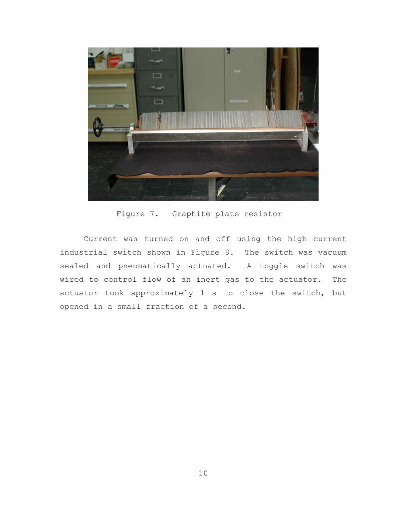
The high currents required a variable resistor which
was capable of dissipating the corresponding I2R losses.
The led to the use of a large stack of graphite plates as a
variable resistor. The number of plates and the
compression on them could be changed to control how much
current flowed through the rails. The graphite plates were
0.5 cm thick and there were 100 plates total. Two copper
plates were moved to alter the number of graphite plates in
the current path. Small partial turns on the compression
wheel adjusted the resistance by micro-ohms. Figure 7
shows the compressible graphite plates and the two copper
plates.
Figure 6. Schematic of model railgun circuit (not to scale)
10
Figure 7. Graphite plate resistor
Current was turned on and off using the high current
industrial switch shown in Figure 8. The switch was vacuum
sealed and pneumatically actuated. A toggle switch was
wired to control flow of an inert gas to the actuator. The
actuator took approximately 1 s to close the switch, but
opened in a small fraction of a second.

11
Figure 8. Meidensha 50 kA vacuum interrupter and breech electrical connection
Liquid metal eutectic electrically coupled the rails
to the bus bars, as shown in Figure 8. The Gallium-Indium
eutectic had relatively small viscosity, but was highly
conductive. Since the eutectic was unable to sustain a
shear force and the rails were suspended, the rails were
entirely free to move. The pendulum suspension system did,
however, provide a small restoring force measured at
approximately 0.025 N.
5. Splitting the Rails
After initial testing was complete, it was deemed
necessary to split the rails (explained in Chapter III,
section C). The rails were cut in the middle at 1 m, and then
each new end had copper tabs attached, just as at the breech

12
and muzzle ends. A polycarbonate block had two reservoirs
filled with eutectic. The block was raised using a lab jack
until the tabs were sufficiently submerged to complete the
circuit’s electrical connectivity. Figures 9 and 10 show
different views of the split rails, ready to energize.
Figure 9. Split rails
Figure 10. Rail tabs submerged in eutectic
13
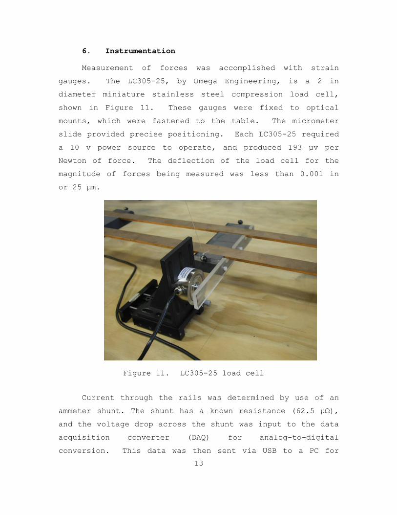
6. Instrumentation
Measurement of forces was accomplished with strain
gauges. The LC305-25, by Omega Engineering, is a 2 in
diameter miniature stainless steel compression load cell,
shown in Figure 11. These gauges were fixed to optical
mounts, which were fastened to the table. The micrometer
slide provided precise positioning. Each LC305-25 required
a 10 v power source to operate, and produced 193 µv per
Newton of force. The deflection of the load cell for the
magnitude of forces being measured was less than 0.001 in
or 25 µm.
Figure 11. LC305-25 load cell
Current through the rails was determined by use of an
ammeter shunt. The shunt has a known resistance (62.5 µΩ),
and the voltage drop across the shunt was input to the data
acquisition converter (DAQ) for analog-to-digital
conversion. This data was then sent via USB to a PC for

14
Labview to process and display continuous real-time current
readings. (Schroeder’s research used an analog voltmeter
and calculations to find the current.) Figure 12 shows the
ammeter shunt with leads.
Figure 12. Ammeter shunt with leads routed to USB-6211 DAQ
During previous research [7], the meter of choice was
an Omega Engineering DP41-B-4R-A-EI 1/8 DIN ultra-high
performance meter, which provided peak force measurements.
The meter used in this research was the superior National
Instruments USB-6211 DAQ. The 6211 provided real-time
continuous data collection via 16 analog inputs with 16
bits of resolution at a sample rate of up to 250 kS/s. The
USB-6211, shown in Figure 13, connects via USB to a laptop,
and is utilized with a Labview program.

15
Figure 13. NI USB-6211 DAQ connected to laptop
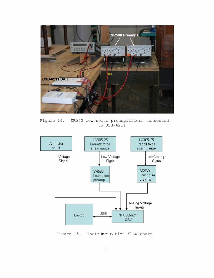
The use of two Stanford Research Systems model SR560
Low Noise Preamplifiers were needed since forces on the
order of 0.01 N produced voltage signals of approximately
2 µv. These preamps provided noise filtering and
amplification prior to input into the USB-6211 DAQ. A
differential input connection was required with twisted
pair wire routing to minimize noise and interference, as
shown in Figure 14. The functional flow of all
instrumentation is displayed in Figure 15.
16
Figure 14. SR560 low noise preamplifiers connected to USB-6211
Figure 15. Instrumentation flow chart

17
III. EXPERIMENTAL PROCEDURE
A. SCOPE
The objective of this experiment was to determine if
recoil forces were seated in the rails. This was attacked
in two phases: 1) simultaneous measurement of the Lorentz
force and rail recoil, and 2) splitting the rails to
further examine the possibility of forces seated in the
rails.
B. RECORDING LORENTZ FORCE AND RECOIL
To capture these forces, one load cell was mounted in
front of the armature, as shown in Figure 16(a). A second
load cell was positioned to detect recoil forces as shown
in Figure 16(b).
Figure 16. Lorentz force armature load cell (a),
recoil force load cell (b)
The circuit was energized by activating the toggle
switch, which initiated the closing of the vacuum
interrupter. After approximately 4 seconds, the circuit
was de-energized. Data recording was initiated
approximately 3 seconds before the circuit was energized,
and ran for 10 seconds.
18
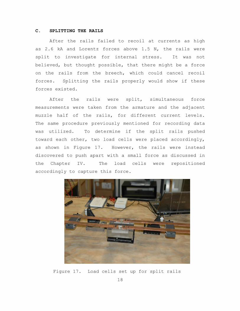
C. SPLITTING THE RAILS
After the rails failed to recoil at currents as high
as 2.6 kA and Lorentz forces above 1.5 N, the rails were
split to investigate for internal stress. It was not
believed, but thought possible, that there might be a force
on the rails from the breech, which could cancel recoil
forces. Splitting the rails properly would show if these
forces existed.
After the rails were split, simultaneous force
measurements were taken from the armature and the adjacent
muzzle half of the rails, for different current levels.
The same procedure previously mentioned for recording data
was utilized. To determine if the split rails pushed
toward each other, two load cells were placed accordingly,
as shown in Figure 17. However, the rails were instead
discovered to push apart with a small force as discussed in
the Chapter IV. The load cells were repositioned
accordingly to capture this force.
Figure 17. Load cells set up for split rails
19
IV. EXPERIMENTAL RESULTS
A. SIMULTANEOUS LORENTZ AND RECOIL FORCES
Force measurements were recorded for current levels up
to 2700 amps. Figure 18 shows a 1200 amp current pulse and
the corresponding forces produced. At 1200 amps, the
Lorentz force magnitude is approximately 10 times greater
than the peak recoil reading, and 30 times greater than the
steady-state recoil. The data shows that higher currents
resulted in recoil forces of the same magnitude, as seen in
Figure 19. These recoil readings are interpreted as
artifacts of the experiment. For larger currents, the I²R
losses produced enough heat to raise the copper’s
resistance. This created the declining current levels seen
in many current pulses.
Additional artifacts are labeled in Figure 18 for
explanation. Table vibrations occurred whenever the high
current switch was opened or closed. The load cells
detected all vibrations, since they were adjusted to be in
contact, or preloaded. When preloaded, the force reading
was set to zero via Labview. Upon separation, this caused
the load cell to produce a negative force reading, or
preload release. To measure a force, the load cell had to
be in contact with the rail support or armature. This
contact between the stainless steel load cell and hard
plastic created bouncing if the two separated and came back
together. These bounces appeared as force oscillations on
the graphs.
As current began to flow, there were transient
mechanical oscillations in the rails and eutectic, which

20
caused the recoil peak. While current flowed through the
eutectic in the armature, the liquid metal was pushed
forward by the Lorentz force. When current stopped
flowing, the eutectic flowed back and the armature would
swing back and bump the rails. This caused the large peaks
in recoil after current flow had stopped.

21
Figure 18. Armature Lorentz force and rail recoil force for 1.2 kA pulse

22
Figure 19. Armature Lorentz forces and rail recoil forces
for 1.2 kA and 2.5 kA pulses

23
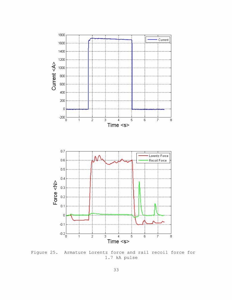
Tables 1 and 2 show how little the peak and steady-
state rail recoil changed, regardless of the current and
armature Lorentz force readings. The Lorentz force column
refers to the force on the armature.
Current (A)
Lorentz Force (N)
Recoil Force-Peak (N)
857.8 0.18 0.036
1218.0 0.29 0.036
1539.3 0.443 0.036
1715.6 0.60 0.024
1849.7 0.72 0.034
2604.9 2.24 0.038
2683.8 2.64 0.030
2741.7 2.70 0.032
Table 1. Peak rail recoil force measurements
Current (A)
Lorentz Force (N)
Recoil Force- Steady State
(N) 863.7 0.17 0.0039
1218.0 0.29 0.0098
1503.8 0.46 0.0106
1681.0 0.59 0.0063
1779.4 0.66 0.0086
2017.3 0.92 0.0083
2235.1 1.23 0.0078
2373.5 1.40 0.0119
2602.7 1.73 0.0102
Table 2. Steady-state rail recoil forces

24
The data in Table 2 is plotted in Figure 20. The
Lorentz force on the armature is directly proportional to
the square of the current while the recoil doesn’t show
consistent or predictable current dependence. The measured
armature force is consistent with Equation (1). The
steady-state force for each data point measures
approximately 0.01 N, or less. The complete real-time
graph for each data point can be viewed in Appendix section
1.
Figure 20. Armature Lorentz force and steady state rail
recoil vs. current

25
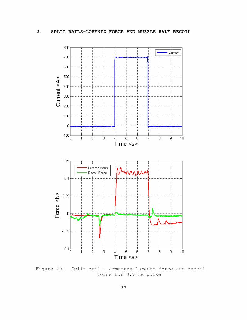
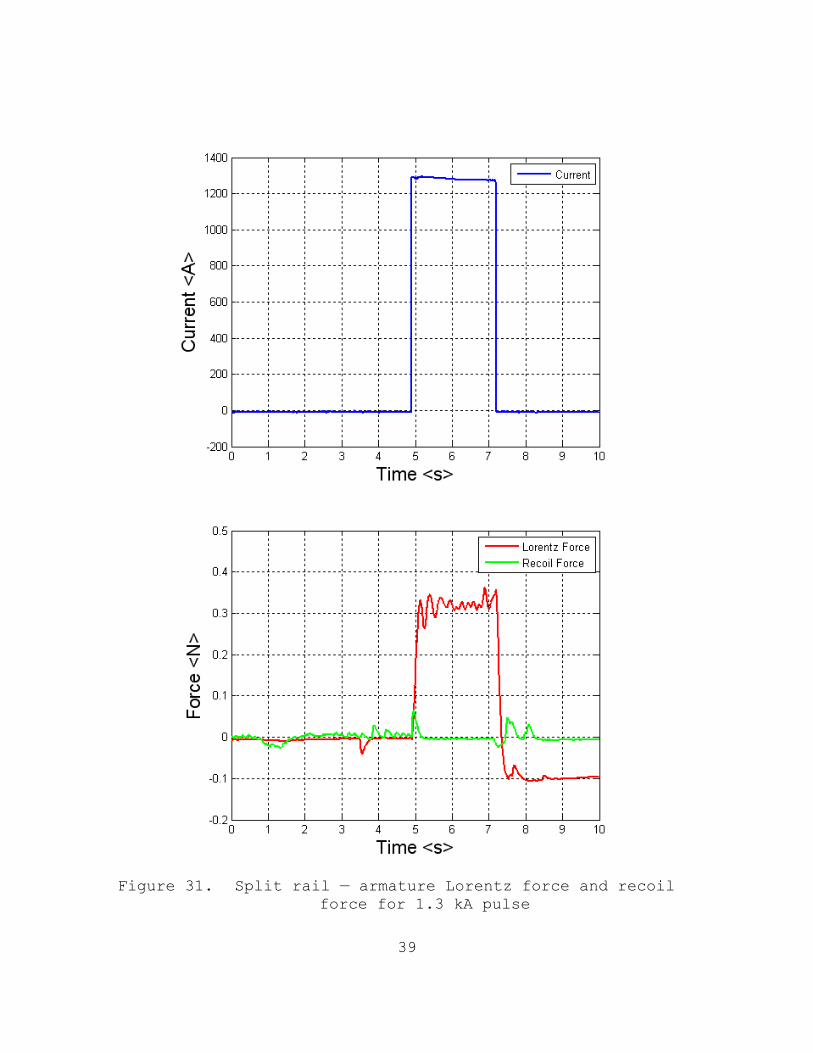
B. SPLIT RAIL MEASUREMENTS
1. Armature Lorentz Force and Recoil on the Muzzle Half Rail
Results of the force comparison between armature
Lorentz force and rail recoil did not change for the muzzle
half of the rails once they were split. Figure 21 shows a
nearly 2 kA current pulse and the forces measured. Results
for other current levels can be view in Appendix section 2.
During brief transient oscillations, as the circuit
energized, the recoil peaked at 0.05 N, which is
approximately 2% of the magnitude of the armature Lorentz
force produced. After the transient, the steady-state
recoil measured less than 0.01 N, which is less than 1% of
the armature Lorentz force measured.

26
Figure 21. Split rails-armature Lorentz force and rail recoil force for 1.8 kA pulse

27
2. Forces Between the Rail Halves
Before the rails were split, it was evident that there
was no net force on the rails. Splitting the rails was
necessary to determine if there were equal and opposite
forces being exerted on the rails. If recoil were seated
in the rails and a canceling force from the breach region
existed, then the rail halves would push together toward
the center of the rails. Instead, the rails were found to
push apart slightly. Figure 22 shows a 2 kA current pulse
and equal and opposite forces of approximately 0.22 N being
exerted on the rails. From separate measurements, similar
current pulses created a Lorentz force of approximately
1 N. With the creation of two more sets of tabs dipped
into eutectic, undesired vertical current components were
introduced and the interactions of these with magnetic
fields would exert forces separating the two halves of the
rails. If one-dimensional current could have been achieved
while splitting the rails, the author believes these
opposing forces would not have existed. Furthermore, these
equal and opposite forces are not believed to exist as
internal stress within unbroken rails.

28
Figure 22. Split rail — Opposing rail forces for 2 kA current pulse

29
C. SUMMARY
An efficient and effective electromagnetic railgun
design rests on a thorough understanding of the forces at
work within the gun. The research in this thesis addresses
the controversial question, “Are recoil forces seated in
the rails?” This question impacts how the gun should be
designed, and what resources would be needed. The weight,
size, and durability will be among the primary concerns
when EM railguns are installed on ships.
This experiment investigated recoil exerted on the
rails by simultaneously measuring armature Lorentz force
and rail recoil with real-time data recording. If the
recoil was seated in the rails, it was expected to have a
magnitude nearly equal to the Lorentz force in the opposite
direction. Simultaneous measurements over a large range of
currents were compared. The max current attained was
2.7 kA, and the measured Lorentz force was 1.7 N, while the
recoil peaked at less than 2% of this value and then
dropped to less than 1%, as seen in Figure 19. Appendix
section 1 shows graphical results for various current
levels, which are consistent with the results in Figure 19.
The recoil readings are not current dependent, and are
interpreted as artifacts of the experiment.
Splitting the rails and simultaneously measuring
armature Lorentz force and recoil on the muzzle half of the
rails yielded results consistent with those for the unsplit
rails. The maximum current attained with this setup was
1.9 kA, and the measured Lorentz force was approximately
1 N, while the steady-state recoil was less than 1% of this
value, as seen in Figure 21. The equal and opposite forces

30
pushing the split rails apart in Figure 22 are interpreted
as an artifact of the experiment, and are not associated
with recoil in any way. The fact that the split rails did
not push toward each other, combined with the results from
the split rail Lorentz-recoil measurements (Figure 21),
leads to the conclusion that there are not any internal
stresses within the rails.
Since there are no indications of internal stresses
and the simultaneous Lorentz-recoil measurements do not
indicate a Lorentz reaction force on the rails, this
experimental investigation has shown that recoil forces are
not seated in the rails.

31
APPENDIX
1. LORENTZ FORCE AND RECOIL
Figure 23. Armature Lorentz force and rail recoil force for 1.2 kA pulse

32
Figure 24. Armature Lorentz force and rail recoil force for 1.5 kA pulse
33
Figure 25. Armature Lorentz force and rail recoil force for 1.7 kA pulse

34
Figure 26. Armature Lorentz force and rail recoil force for 1.8 kA pulse

35
Figure 27. Armature Lorentz force and rail recoil force for 2.6 kA pulse

36
Figure 28. Armature Lorentz force and rail recoil force for 2.7 kA pulse
37
2. SPLIT RAILS—LORENTZ FORCE AND MUZZLE HALF RECOIL
Figure 29. Split rail — armature Lorentz force and recoil force for 0.7 kA pulse

38
Figure 30. Split rail — armature Lorentz force and recoil force for 1.2 kA pulse
39
Figure 31. Split rail — armature Lorentz force and recoil force for 1.3 kA pulse

40
Figure 32. Split rail — armature Lorentz force and recoil force for 1.3 kA pulse

41
Figure 33. Split rail — armature Lorentz force and recoil force for 1.4 kA pulse

42
Figure 34. Split rail — armature Lorentz force and recoil force for 1.4 kA pulse

43
Figure 35. Split rail — armature Lorentz force and recoil force for 1.9 kA pulse

44
Figure 36. Split rail — armature Lorentz force and recoil force for 2 kA pulse

45
3. SPLIT RAILS—OPPOSING FORCES ON EACH RAIL HALF
Figure 37. Split rail — opposing rail forces for 1.1 kA current pulse

46
Figure 38. Split rail — opposing rail forces for 1.2 kA current pulse

47
Figure 39. Split rail — opposing rail forces for 1.4 kA current pulse

48
THIS PAGE INTENTIONALLY LEFT BLANK

49
LIST OF REFERENCES
[1] S. Sandro and R. Wilson, “Romagnosi and the discovery of electromagnetism,” Accademia dei Lincei, Series 9, volume 11, issue 2, pp. 137–142, 2000.
[2] “Hans Christian Ørsted,” Encyclopedia Britannica Online, http://www.britannica.com/EBchecked/topic/433282/Hans-Christian-Orsted (accessed November 20, 2009).
[3] I.V. Hogg, The Guns: 1939/45. London: Macdonald and Co., 1969.
[4] O. Darrigol, Electrodynamics from Ampère to Einstein, Oxford, [England]: Oxford University Press, 200, p. 327.
[5] I.E. Allen and T.V. Jones, “Relativistic recoil and the railgun,” J. App. Phys., volume 67, pp. 18-21, 1990.
[6] J. E. Allen, “Railgun recoil and relativity” J. Appl. Phys., volume 20, pp. 1073, 1987.
[7] H. Aspden, “The exploding wire phenomenon,” Physics Letters, volume 107A, pp. 238-240, February 1985.
[8] T. H. Boyer, “Energy and momentum in electromagnetic field for charged particles moving with constant velocities,” Am. J. Phys., volume 39, pp. 257-270, March 1971.
[9] B. R. Casserberg, “Electromagnetic momentum introduced simply,” Am. J. Phys., volume 50, pp. 415-416, May 1982.
[10] P. Graneau and P. N. Graneau, “Electrodynamic momentum measurements,” J. Phys. D: Appl. Phys., volume 21, p. 1826, 1988.
[11] P. Graneau and N. Graneau, “The electromagnetic impulse pendulum and momentum conservation,” Nuovo Cimento, volume 7D, pp. 31–45, 1986.

50
[12] T. K. Hsieh, “A Lagrangian formulation for mechanically, thermally coupled electromagnetic diffusive processes with moving conductors,” IEEE Trans. Mag., volume 31, no. 1, 1995.
[13] L. Johansson, “Longitudinal electrodynamic forces–and their possible technological applications,” Master’s thesis, Lund Institute of Technology, Lund Sweden, September 1996.
[14] E. L. Kathe, “Recoil Considerations for Railguns,” IEEE Trans. Mag., volume 37, no 1, Part 1, pp. 425-430, January 2001.
[15] M. Löffler, “Recoil forces in electromagnetic accelerators—A short review,” in Proc. 4th Euro. Symp. Electromagn. Launch Technol., Celle, Germany, May 1993.
[16] R. A. Marshall and L. C. Woods, “Comment: Origin, location, magnitude and consequences of recoil in the plasma armature railgun,” Inst. Elect. Eng. Proc. Sci. Meas. Technol., volume 144, pp. 49–51, 1997.
[17] P. G. Moyssides, “Pendulum Experiments and the Fundamental Laws of Electrodynamics,” Inst. Elect. Eng. Proc. Sci. Meas. Technol., volume 35, no. 2, March 1999.
[18] P. Graneau and N. Graneau, “Railgun Recoil Forces Cannot Be Modeled as Gas Pressure,” IEEE Trans. Magn., volume 33 no. 6, p. 18, 1997.
[19] M. Pollack and L. W. Matsch, “Electric gun and power source,” Armour Research Foundation Report No. 3, Project 15-391E, May 1, 1947.
[20] A. E. Robson and J. D. Sethian, “Railgun recoil, ampere tension, and the laws of electrodynamics,” Am. J. Phys., volume 60, pp. 1111-1117, December 1992.
[21] J. J. G. Scanio, “Conservation of momentum in electrodynamics-an example,” Am. J. Phys., volume 43, pp. 258-260, March 1975.

51
[22] D. Sadedin, "Conservation of Momentum and Recoil in the Railgun,” IEEE Trans, volume 33 no. 1, pp. 599-603, 1997.
[23] J. G. Ternan, “Equivalence of the Lorentz and Ampere force laws in magnetostatics,” J. Appl. Phys., volume 57, pp. 1743-1745, 1985
[24] W. Weldon, M. Driga, and H. Woodson, “Recoil in Electromagnetic Railguns,” IEEE Trans, volume 22 no. 6, pp. 1808-1811, November 1986.
[25] J. P. Wesley, “On Peoglos’ measurement of the force on a portion of a current loop due to the remainder of the loop,” J. Phys. D: Appl. Phys., volume 22, pp. 849-850, 1989.
[26] A. E. Witalis, “Origin, location, magnitude and consequences of recoil in the plasma armature railgun,” Inst. Elect. Eng. Proc. Sci. Meas. Technol., volume 142, pp. 197–200, 1995.
[27] P. Graneau, “Amperian recoil and the efficiency of railguns,” J. Appl. Phys., volume 62, pp. 3006-3009, 1987.
[28] W.B. Maier, “Selected Topics in Railgun Technology” (revised September 3, 2008), Course Notes, Naval Postgraduate School, Monterey, CA, 2008.
[29] R. Ellis, Technical Director, USN EM Railgun INP, Office of Naval Research, Arlington, VA.
[30] M. Schroeder, “An investigation of the static force balance of a model railgun,” Master’s thesis, Naval Postgraduate School, Monterey, CA, 2007.

52
THIS PAGE INTENTIONALLY LEFT BLANK

53
INITIAL DISTRIBUTION LIST
1. Defense Technical Information Center Ft. Belvoir, Virginia
2. Dudley Knox Library Naval Postgraduate School Monterey, California
3. William B. Maier II Physics Department Code PHMW Naval Postgraduate School Monterey, California
4. Railgun Research Group Physics Department Code PH Naval Postgraduate School Monterey, California
5. CAPT David Kiel PMS 405 Naval Sea Systems Command Washington Navy Yard Washington, DC
6. Dr. Roger McGinnis PMS 405 Naval Sea Systems Command Washington Navy Yard Washington, DC
7. Gene Nolting PMS 405 Naval Sea Systems Command Washington Navy Yard Washington, DC
8. Fred Beach Institute of Advanced Technology University of Texas at Austin Austin, Texas

54
9. Dr. Elizabeth D’Andrea Director, Swampworks Office of Naval Research Arlington, Virginia
10. Bob Turman Sandia National Laboratories, New Mexico Albuquerque, New Mexico
11. Stephen Bayne US Army Research Laboratory Adelphi, Maryland
12. Ian McNab Institute of Advanced Technology University of Texas at Austin Austin, Texas
13. Roger Ellis Naval Sea Systems Command, Dahlgren Dahlgren, Virginia
14. Matthew Cilli ARDEC Picatinny Arsenal Picatinny, New Jersey
15. Edward Schmidt ARDEC Aberdeen Proving Ground Aberdeen, Maryland
16. D. S. Sorenson Los Alamos National Laboratory Los Alamos New Mexico
17. Jack Bernardus NSWC, Dahlgren Dahlgren, Virginia.
18. Andres Larraza Physics Department Chair Naval Postgraduate School Monterey, California

55
19. Prof. Hans Mark Institute for Advanced Technology Austin, Texas
20. Bruce Denardo Physics Department Naval Postgraduate School Monterey, California