an experimental study of water bleve
TRANSCRIPT

HAL Id: hal-02414514https://hal.archives-ouvertes.fr/hal-02414514
Submitted on 16 Dec 2019
HAL is a multi-disciplinary open accessarchive for the deposit and dissemination of sci-entific research documents, whether they are pub-lished or not. The documents may come fromteaching and research institutions in France orabroad, or from public or private research centers.
L’archive ouverte pluridisciplinaire HAL, estdestinée au dépôt et à la diffusion de documentsscientifiques de niveau recherche, publiés ou non,émanant des établissements d’enseignement et derecherche français ou étrangers, des laboratoirespublics ou privés.
An Experimental Study of Water BLEVEFrederic Heymes, Pierre Lauret, Pol Hoorelbeke
To cite this version:Frederic Heymes, Pierre Lauret, Pol Hoorelbeke. An Experimental Study of Water BLEVE. ChemicalEngineering Transactions, AIDIC, 2019, 77, �10.3303/CET1977035�. �hal-02414514�

CHEMICAL ENGINEERING TRANSACTIONS
VOL. 77, 2019
A publication of
The Italian Association of Chemical Engineering Online at www.cetjournal.it
Guest Editors: Genserik Reniers, Bruno FabianoCopyright © 2019, AIDIC Servizi S.r.l. ISBN 978-88-95608-74-7; ISSN 2283-9216
An Experimental Study of Water BLEVEFrederic Heymesa,*, Pierre Laureta, Pol Hoorelbekeb
a IMT Mines Ales, 6 avenue de Clavières 30319 Ales b Total SA, 24 Cours Michelet 92069 Paris La Défense Cedex [email protected]
A boiling liquid expanding vapor explosion (BLEVE) is an explosion caused by a sudden rupture of a vessel containing a pressurized liquid at a temperature above its boiling point. A BLEVE can occur with all types of liquids and is not a particular phenomenon for flammable liquefied gases such as propane or butane. A particular hazard in the hydrocarbon industry is the use of water at temperatures far above their atmospheric boiling point in steam generation systems. Water is present at high pressure (e.g. 7 MPa) and high temperature (e.g. 300°C). At these conditions the water is superheated and in case of an accidental release the water will undergo a rapid vaporization and a BLEVE type explosion can be expected. This hazard is quit wide spread in all refineries, petrochemical plants, etc. but little data can be found in literature about real size water BLEVE experiments. The aim of this work was to perform BLEVE tests thanks to a 14L pressure vessel designed on purpose to produce high pressure water BLEVE (85 bar). An extended set of pressure gauges was set in the vessel to measure the internal phase change pressure dynamics and around the relief rupture disk to capture the blast wave. Temperature of water was also recorded, and a fast camera (Phantom V2512) was used to see the phenomenon. Data show clearly the pressure recovery in the vessel and multiple blast waves around the vessel. Results are discussed to analyse the risk of water BLEVE.
1. Introduction
Steam is widely used in industry to carry heat. After condensation, hot water flows usually back to a furnace to be reheated and vaporized. Steam is produced and used at different temperatures and pressure. Typically, steam below 3.5 barg is termed as low pressure steam. Steam above 3.5 barg but below 17.5 barg is termed as medium pressure steam and steam above 17.5 barg is termed as high pressure steam. Some users define their steam above 40 barg as ultra-high pressure steam. A water-steam circuit will comprise sections of piping where water flows at high pressure and high temperature. In case of a leak the hot water will undergo a rapid transformation into steam due to violent boiling or flashing. This phenomenon is called a steam explosion. The degree of superheat (i.e. the difference between the temperature of the water and the atmospheric boiling temperature of the water) determines the violence of the explosion. The water vaporizes from liquid to vapour with extreme speed, increasing dramatically in volume. A steam explosion sprays steam and boiling-hot water and the hot medium that heated it in all directions, creating a danger of burning. Some steam explosions appear to be special kinds of boiling liquid expanding vapour explosion (BLEVE), and rely on the release of stored superheat.
2. Theoretical considerations
2.1 Phase Diagram (P-T)
Water thermodynamic properties were widely investigated previously. Phase change lines, triple point (T= 0°C; P= 0.66173 Bar) and critical point (T= 373.946 °C; P=220.6 Bar) are given on Figure 1 (Abbasi & Abbasi 2007).
DOI: 10.3303/CET1977035
Paper Received: 25 October 2018; Revised: 30 April 2019; Accepted: 23 June 2019
Please cite this article as: Heymes F., Lauret P., Hoorelbeke P., 2019, An Experimental Study of Water BLEVE, Chemical Engineering Transactions, 77, 205-210 DOI:10.3303/CET1977035
205

Figure 1. Phase change diagram of water in (T,P) coordinates
Figure 2. Coexistence line (BCB’), isotherm at equilibrium (ABB’D), liquid spinodal (CE) and vapor spinodal (CF) in case of water
A liquid, such as water, can be superheated which means that it is in liquid form at a temperature which is higher than its boiling point but without boiling. Superheating is achieved by heating a homogeneous substance in a clean container, free of nucleation sites, while taking care not to disturb the liquid. More generally, a liquid is said to be superheated when its temperature exceeds its saturation temperature of its pressure or when its pressure decreases below its saturation pressure of its temperature while the liquid is still not boiling: TL > Tsat(PL) or PL < P (TL). Superheating may happen at any pressure below the critical point. Superheat domain is usually delimited by a line defined between the critical point and the superheat limit temperature at atmospheric pressure. The superheat state may be described on the usual P-V diagram as following (Figure 2). C is the critical point. [BCB’] is the saturation curve or the binodal. The isotherm at temperature T=306.85°C is [ABEFB’D]. B and B′ are equilibrium states on the binodal. Psat is the equilibrium pressure at T. When the liquid state is between A and B, it is called the subcooled liquid. The liquid at point B is called the saturated liquid. When the liquid state is between B and E, it is called the superheated liquid because its temperature has been higher than the saturation temperature of its pressure or its pressure has been lower than the saturation pressure of its temperature. When the liquid becomes superheated, it also becomes metastable which means its stability can be easily broken by external perturbations. If so, it can no longer maintain its liquid state and phase transition must occur. When the metastability of the liquid becomes larger (the liquid is approaching point E), the minimum perturbation required to break the stability of the liquid becomes smaller and finally at point E, the thermodynamic stability limit has been reached, which means phase transition will spontaneously occur without any external perturbations or without any suitable nucleation site. Therefore it can release a large amount of energy in explosive behavior. A superheated liquid explosion requires that a large part of the liquid vaporizes in very short time. Different behaviors were described in literature. Two main categories can be made, according to the way the liquid becomes superheated: By sudden pressure loss, such as observed in boiling liquid expanding vapor explosion (BLEVE) By sudden temperature increase, such as observed in rapid phase transition (RPT)
2.2 The Boiling Liquid Expanding Vapour Explosion (BLEVE)
BLEVE is the most common phenomena which resulted in many studies. The standard theory of BLEVE was originally proposed by (Reid, 1979). The essential idea is illustrated in Figure 1. Under normal conditions the content of the vessel containing a liquid and its vapor is in thermodynamic equilibrium and the pressure and temperature combination lies at the saturation curve (points A or C). In the case of vessel rupture the pressure suddenly decreases resulting in superheated liquid. There is a limit to the degree in which a liquid can get superheated. At constant pressure, the superheat limit temperature is the highest temperature that a liquid can sustain without undergoing phase transition and at constant temperature; the superheat limit pressure is the lowest pressure for a liquid to maintain its liquid state. According to Reid’s theory, when the pressure of the liquid decreases from point C to D, the liquid reaches the superheat limit curve and a BLEVE will occur while in the process of A to B, the liquid does not reach the superheat limit curve, no BLEVE will occur.
206
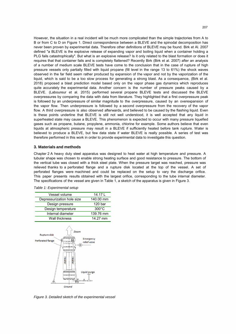
Vessel volume 14.17 L Depressurization hole size 140.00 mm
Design pressure 120 bar Design temperature 300°C
Internal diameter 139.76 mm Wall thickness 14.27 mm
However, the situation in a real incident will be much more complicated than the simple trajectories from A to B or from C to D on Figure 1. Direct correspondence between a BLEVE and the spinodal decomposition has never been proven by experimental data. Therefore other definitions of BLEVE may be found. Birk et Al. 2007 defined "a BLEVE is the explosive release of expanding vapor and boiling liquid when a container holding a PLG fails catastrophically". But what is an explosive release? Is it only related to the blast formation or does it requires that that container fails and is completely flattened? Recently Birk (Birk et al. 2007) after an analysis of a number of medium scale BLEVE tests have come to the conclusion that in the case of rupture of high pressure vessels only partially filled with liquid propane (fill level in the range 13 to 61%) the shock waves observed in the far field seem rather produced by expansion of the vapor and not by the vaporization of the liquid, which is said to be a too slow process for generating a strong blast. As a consequence, (Birk et al. 2018) proposed a blast prediction model based only on the vapor phase gas dynamics which reproduces quite accurately the experimental data. Another concern is the number of pressure peaks caused by a BLEVE. (Laboureur et al. 2015) performed several propane BLEVE tests and discussed the BLEVE overpressures by comparing the data with data from literature. They highlighted that a first overpressure peak is followed by an underpressure of similar magnitude to the overpressure, caused by an overexpansion of the vapor flow. Then underpressure is followed by a second overpressure from the recovery of the vapor flow. A third overpressure is also observed afterwards, and believed to be caused by the flashing liquid. Even is these points underline that BLEVE is still not well understood, it is well accepted that any liquid in superheated state may cause a BLEVE. This phenomenon is expected to occur with many pressure liquefied gases such as propane, butane, propylene, ammonia, chlorine for example. Some authors believe that even liquids at atmospheric pressure may result in a BLEVE if sufficiently heated before tank rupture. Water is believed to produce a BLEVE, but few data state if water BLEVE is really possible. A series of test was therefore performed in this work in order to provide experimental data to investigate this question.
3. Materials and methods
Chapter 2 A heavy duty steel apparatus was designed to heat water at high temperature and pressure. A tubular shape was chosen to enable strong heating surface and good resistance to pressure. The bottom of the vertical tube was closed with a thick steel plate. When the pressure target was reached, pressure was relieved thanks to a perforated flange and a rupture disk located at the top of the vessel. A set of perforated flanges were machined and could be replaced on the setup to vary the discharge orifice. This paper presents results obtained with the largest orifice, corresponding to the tube internal diameter. The specifications of the vessel are given in Table 1, a sketch of the apparatus is given in Figure 3.
Table 1: Experimental setup
Figure 3. Detailed sketch of the experimental vessel
207
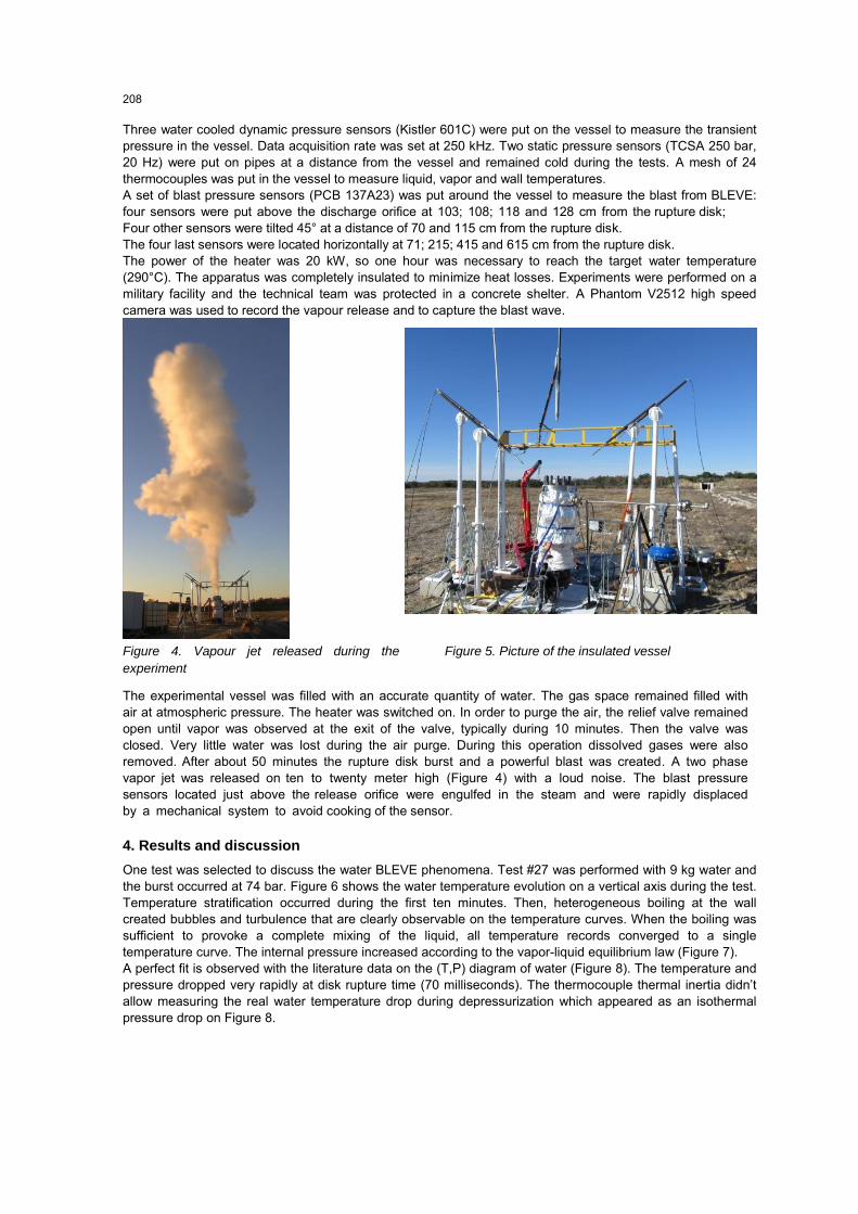
Three water cooled dynamic pressure sensors (Kistler 601C) were put on the vessel to measure the transient pressure in the vessel. Data acquisition rate was set at 250 kHz. Two static pressure sensors (TCSA 250 bar, 20 Hz) were put on pipes at a distance from the vessel and remained cold during the tests. A mesh of 24 thermocouples was put in the vessel to measure liquid, vapor and wall temperatures. A set of blast pressure sensors (PCB 137A23) was put around the vessel to measure the blast from BLEVE: four sensors were put above the discharge orifice at 103; 108; 118 and 128 cm from the rupture disk; Four other sensors were tilted 45° at a distance of 70 and 115 cm from the rupture disk. The four last sensors were located horizontally at 71; 215; 415 and 615 cm from the rupture disk. The power of the heater was 20 kW, so one hour was necessary to reach the target water temperature (290°C). The apparatus was completely insulated to minimize heat losses. Experiments were performed on a military facility and the technical team was protected in a concrete shelter. A Phantom V2512 high speed camera was used to record the vapour release and to capture the blast wave.
Figure 4. Vapour jet released during the experiment
Figure 5. Picture of the insulated vessel
The experimental vessel was filled with an accurate quantity of water. The gas space remained filled with air at atmospheric pressure. The heater was switched on. In order to purge the air, the relief valve remained open until vapor was observed at the exit of the valve, typically during 10 minutes. Then the valve was closed. Very little water was lost during the air purge. During this operation dissolved gases were also removed. After about 50 minutes the rupture disk burst and a powerful blast was created. A two phase vapor jet was released on ten to twenty meter high (Figure 4) with a loud noise. The blast pressure sensors located just above the release orifice were engulfed in the steam and were rapidly displaced by a mechanical system to avoid cooking of the sensor.
4. Results and discussion
One test was selected to discuss the water BLEVE phenomena. Test #27 was performed with 9 kg water and the burst occurred at 74 bar. Figure 6 shows the water temperature evolution on a vertical axis during the test. Temperature stratification occurred during the first ten minutes. Then, heterogeneous boiling at the wall created bubbles and turbulence that are clearly observable on the temperature curves. When the boiling was sufficient to provoke a complete mixing of the liquid, all temperature records converged to a single temperature curve. The internal pressure increased according to the vapor-liquid equilibrium law (Figure 7). A perfect fit is observed with the literature data on the (T,P) diagram of water (Figure 8). The temperature and pressure dropped very rapidly at disk rupture time (70 milliseconds). The thermocouple thermal inertia didn’t allow measuring the real water temperature drop during depressurization which appeared as an isothermal pressure drop on Figure 8.
208

Figure 6. Temperature of the fluids Figure 7. Pressure in the tank
Figure 8. Thermodynamic transformation on phase diagram (Test #6)
Figure 9. High speed camera capture of the blast waves
Figure 10 represents two key data during the violent phase change: internal pressure and blast pressure (at 70 cm from the rupture disk) were reported on a synchronized time scale. After a short depressurization, a small re-pressurization occurred and was measured with both pressure transducers (only one is represented). This re-pressurization was sufficient to keep a constant pressure during 11 milliseconds, the pressure restarted to decrease to reach atmospheric pressure (42 milliseconds were required).
Figure 10. Dynamic pressure in the tank and blast at 70 cm from the rupture disk
209

A clear blast pressure peak can be observed on Figure 10, 1.642 milliseconds after the disk rupture. This pressure peak was followed by a classical negative pressure phase and a second peak was observed. The negative phase is believed to be caused by an overexpansion of the vapor flow. It is not very clear if this second peak can be attributed to the liquid phase change or to the recovery of the vapor flow. No third peak was observed on a whole set of blast pressure gauges. The high speed camera movie showed clearly the two blasts above the tank. The two blast waves are visible on the fastcam pictures because of the refractive index change of air due to local pressure increase. To facilitate understanding Figure 9, the blast waves were highlighted by curves and arrows to indicate the position of the refractive index change which is not visible on the picture.
5. Conclusion
An experimental work was undertaken to investigate the possibility of water BLEVE at (290°C; 75 bar). Experimental data showed that several blasts were produced and that a re-pressurization peak was observed in the vessel. The criteria of “explosive boiling” seem to be respected; however, no blast seemed to be produced by the violent phase change and the tank was not destroyed during the explosive boiling, which is observed in most BLEVE tests. Several questions may be raised about the tubular shape of the vessel and the low superheated state of water during these tests. Next work will consider the experimental data focusing on energy from vapour and liquid phase that is converted into blast. The most valuable question about these experiments is not to decide if a BLEVE occurred or not, but which effects can be feared in industry.
Acknowledgments
The authors are grateful to Total SA for supporting this research work.
References
Abbasi T., Abbasi S.A., 2007, Accidental risk of superheated liquids and a framework for predicting the superheat limit, Journal of Loss Prevention in the Process Industries, 20, 165–181.
Birk A.M., Davison C., Cunningham M., 2007, Blast overpressures from medium scale BLEVE tests, Journal of Loss Prevention in the Process Industries, 20, 194–206.
Birk A.M., Heymes F., Eyssette R., Lauret P., Aprin L., Slangen P., 2018, Near-field BLEVE overpressure effects: The shock start model, Process Safety and Environmental Protection, 116, 727-736.
Laboureur D., Birk A.M., Buchlin J.M., Rambaud P., Aprin L., Heymes F., Osmont A., 2015, A closer look at BLEVE overpressure, Process Safety and Environmental Protection, 95, 159-171.
Lauret P., Slangen P., Heymes F., Aprin L., Lecysyn N., Osmont A., 2017, Natural background oriented schlieren and multiscale visualizations of overpressure wave resulting from vapor cloud explosion, 11th Pacific Symposium on Flow Visualization and Image Processing, 1-3 december, Kumamoto, Japan.
Reid R.C., 1979, Possible mechanism for pressurized-liquid tank explosions or BLEVE’s, Science, 203, 1263– 1265.
210