an extensible and lightweight architecture for adaptive server applications
TRANSCRIPT
SOFTWARE—PRACTICE AND EXPERIENCESoftw. Pract. Exper. 2008; 38:853–883Published online 26 October 2007 inWiley InterScience (www.interscience.wiley.com). DOI: 10.1002/spe.857
An extensible and lightweightarchitecture for adaptive serverapplications
Ian Gorton1, Yan Liu2,∗,† and Nihar Trivedi3
1Pacific Northwest National Laboratory, Richland, WA, U.S.A.2National ICT Australia Ltd, Australian Technology Park, Garden Street, NSW,
Australia‡3School of Information Technologies,University of Sydney, Sydney, NSW, Australia
SUMMARY
Server applications augmented with behavioral adaptation logic can react to environmental changes,creating self-managing server applications with improved quality of service at runtime. However, devel-oping adaptive server applications is challenging due to the complexity of the underlying server tech-nologies and highly dynamic application environments. This paper presents an architecture framework,the Adaptive Server Framework (ASF), to facilitate the development of adaptive behavior for legacyserver applications. ASF provides a clear separation between the implementation of adaptive behaviorand the business logic of the server application. This means a server application can be extended withprogrammable adaptive features through the definition and implementation of control components definedin ASF. Furthermore, ASF is a lightweight architecture in that it incurs low CPU overhead and memoryusage. We demonstrate the effectiveness of ASF through a case study, in which a server applicationdynamically determines the resolution and quality to scale an image based on the load of the server andnetwork connection speed. The experimental evaluation demonstrates the performance gains possible byadaptive behavior and the low overhead introduced by ASF. Copyright © 2007 John Wiley & Sons, Ltd.
Received 14 September 2006; Revised 22 August 2007; Accepted 24 August 2007
KEY WORDS: adaptive; server applications; autonomic computing; components; performance
1. INTRODUCTION
Application server platforms encompass advance middleware technologies and provide a stan-dardized service layer to support the development and deployment of distributed, server-sideapplications. Application server technologies such as CORBA, J2EE and .NET can be used to build
∗Correspondence to: Yan Liu, National ICT Australia Ltd, Australian Technology Park, Garden Street, NSW, Australia.†E-mail: [email protected]‡National ICT Australia is funded through the Australian Government’s Backing Australia’s Ability initiative, in part throughthe Australian Research Council.
Copyright q 2007 John Wiley & Sons, Ltd.
854 I. GORTON, Y. LIU AND N. TRIVEDI
server applications that support various levels of quality of service, making them suitable platformsfor software systems with demands for high performance and reliability.However, these mission-critical server applications remain challenging to construct and maintain.
With the rapid evolution of technologies, fully fledged application servers are becoming moreand more complex application-hosting environments, with hundreds of parameters to be tuned,configured or indirectly stimulated or triggered when components of applications are deployed andexecuted. Moreover, server applications operate in dynamic environments with variable requestloads, fluctuating resource usage and unpredictable system faults. It is therefore difficult, if notimpossible, to statically optimize the quality goals (such as performance and reliability) of anapplication in all circumstances.To reduce application configuration and management complexity, creating server applications
with self-management and adaptation capabilities is being explored. Adaptation in applicationservers can be achieved using three different strategies, namely structure adaptation, architectureadaptation and behavior adaptation. Structure adaptation means changing the type of applicationcomponents, such as a method signature. Aspect-oriented programming techniques have been usedto achieve structure adaptation [1]. Architecture adaptation uses a system’s software architecturalmodel to monitor and reason about the system. This results in changes in the structure of componentsand their interactions [2]. For example, a new server instance is launched within a server clusterwhen the workload increases. Behavioral adaptation, as described in this paper, focuses on changingthe execution of existing components in a non-intrusive way, such as changing the configurationof a component, and intercepting the requests and replies of a method invocation. These threetechniques can also be combined to deliver highly adaptive solutions.Initial steps towards adaptive technologies follow two main paths. The first path is building self-
management capabilities into application server platforms and creating self-managing solutionsthrough prepacked components and services. For example, IBM’s WebSphere application serverproduct is currently integrated with other IBM autonomic computing toolkits such as load balancingand log analysis [3].The second path is exploring enhancing existing application components with adaptation using
ad hoc programming language features such as complex conditional expressions, reflection andexceptions. However, these approaches have significant drawbacks, as the adaptation and applicationbusiness logic are interweaved and tightly coupled, leading to complex testing and poor extensi-bility and maintainability. Moreover, for many legacy applications such as off-the-shelf packages,modifying the source code is often not possible or desirable.A solution to these problems is to separate the adaptation logic from the application business
logic. This requires software infrastructure support so that the application programmer is relieved ofconcerns regarding the adaptive logic implementation. For server applications executing on appli-cation server platforms, this approach can be achieved by extending existing application serverplatforms with adaptive mechanisms [2]. By augmenting existing middleware, it becomes possibleto transparently build adaptive capabilities into existing applications. It also promotes an attrac-tive adoption path for new adaptive applications that remain based on standard application serverplatforms.Other approaches for developing adaptive server applications have been investigated [4,5].
However, they typically require the application to be developed using custom middleware withspecialized application programming interfaces (APIs) and languages. This makes it infeasible touse these platforms to augment existing applications with adaptive behavior.
Copyright q 2007 John Wiley & Sons, Ltd. Softw. Pract. Exper. 2008; 38:853–883DOI: 10.1002/spe
AN EXTENSIBLE AND LIGHTWEIGHT ARCHITECTURE 855
Regardless of the precise approach adopted, developing flexible and efficient adaptive controllogic for server applications is challenging for at least three reasons. First, the ability to handledynamic control must be addressed, as adaptation must occur at runtime in response to changesin the application’s environment. Second, the overheads introduced by external control mecha-nisms must be low, so that the execution of control logic does not adversely affect applicationperformance and resource usage. Third, in order to reduce the cost of development of adap-tive behavior, control logic needs to be implemented in separable modules that can be modified,extended and reused across different systems without affecting the main business logic of anapplication.A flexible architecture is therefore essential to support the efficient implementation of adaptive
behavior in a non-intrusive way [6]. In this paper we present such an architecture framework,the Adaptive Server Framework (ASF), to support the development of behavioral adaptation forserver-side components running on application servers. The major contributions of our approach,as embodied in ASF, are the following:
1. ASF provides an extensible architecture framework for building application-specific adaptivebehavior into server applications.
2. ASF supports a clear separation between application business logic and adaptive control logic.3. ASF introduces low overheads in terms of performance and memory footprint.4. ASF is built on standard interfaces and is portable across different J2EE application server
platforms.5. ASF demonstrates that adaptive capability can be successfully enhanced on top of existing
middleware layers to facilitate the transparent augmentation of legacy applications with adap-tive behavior.
The remainder of this paper describes ASF and a case study that we have implemented todemonstrate its suitability for building adaptive server applications.
2. RELATED WORK
Behavioral adaptation of server applications is encompassed within the autonomic computingresearch domain. The blueprint for software architectures in autonomic computing is describedin [7]. The challenges of developing autonomic computing systems are addressed at two levels,namely developing self-managing, self-tuning and self-adaptive autonomic elements and that of theinteractions between autonomic elements. Reference architectures for autonomic computing havebeen developed from research prototypes, for example, Unity [8].The explicit properties assumed by Unity are that each autonomic element must be self-managing
internally and be self-healing locally. On the basis of these assumptions, Unity focuses on theinteractions between autonomic elements. Interfaces are defined to restrict the communicationbetween elements via web services, and elements register and locate services through a repositoryusing policies specified for services. In contrast, in this paper, we consider a deployable serverapplication to be an autonomic computing element and focus on how to implement self-managing,autonomic behavior for new or legacy single-server applications.The Rainbow project [2] proposes an architecture adaptation approach with emphasis on adaptive
strategies and techniques for detecting architectural styles at runtime. In Rainbow, adaptation is
Copyright q 2007 John Wiley & Sons, Ltd. Softw. Pract. Exper. 2008; 38:853–883DOI: 10.1002/spe
856 I. GORTON, Y. LIU AND N. TRIVEDI
predefined based on the architectural styles of the system. An architectural model that is representedas a graph of interacting computational elements is used to reason about what architectural changesare needed. In comparison, ASF is more focused on a software framework supporting behavioraladaptation. Specifically it addresses how application-specific adaptive behavior can be incorporatedinto existing systems. One common design principle of Rainbow and ASF is that adaptive controlshould be modular and separated from the managed application, interacting with the application ina non-intrusive way.Research in reflective and adaptive middleware also provides infrastructures that can adapt their
quality-of-service provision based on environmental needs (e.g. [9–11]). These technologies facil-itate dynamic adaptation of a middleware platform by applications in ways that were not antici-pated during its design [12]. Adaptation is driven by applications using a reflective API that theunderlying middleware platform supports. Such platforms are consequently translucent, allowingapplications access to components inside the middleware. This contrasts with our approach inASF, which completely separates control of adaptive behavior from the application’s businesslogic.Other tools and runtime techniques to support the construction of adaptive applications are
reported in [13]. Efforts have focused on designing autonomic services in application server tech-nologies to make the deployed servers less costly and complex to manage. These solutions focuson system manageability and are not flexible enough to address application-specific needs forfunctional adaptation.Within an autonomic element, analytical models and intelligence play key roles in controlling
and guiding adaptive behavior. Menasce [14] and Wildstrom et al. [15] demonstrate how modelsfor analysis can be useful in reconfiguring system resources subject to changing workloads. In thispaper, models for analysis are deployed as ASF control components to control adaptation at theapplication level.
3. ADAPTIVE SERVER FRAMEWORK
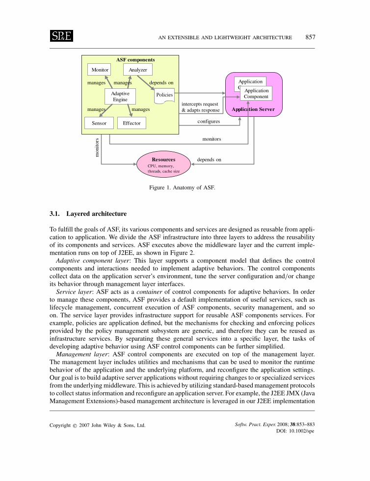
The fundamental design principle of ASF is to separate the implementation of adaptive behaviorfrom the server application business logic. This means the adaptation should be encapsulated intocomponents external to the application implementation. Hence, the goal of ASF is to provideinfrastructure components and services to facilitate the construction of behavioral adaptation. This isachieved by creating a component model for developing adaptive control components and providingassociated services that support the deployment of adaptive components with J2EE applicationservers.Figure 1 depicts an overview of how ASF interacts with applications and the underlying appli-
cation server platform. ASF defines a component architecture for implementing dynamic, adaptivecontrol, such as managing the lifecycle of control components and coordinating their commu-nications. Adaptive logic implemented using ASF components runs in an adaptive engine. ASFcomponents interact with the application server, monitor the runtime environment, analyze collecteddata and change the application’s behavior by adapting the response or setting the server’s config-uration to fulfill the business goals. In this way, ASF helps developers to focus on the design andimplementation of adaptive logic and insulates them from the complexities of the underlying J2EEplatform.
Copyright q 2007 John Wiley & Sons, Ltd. Softw. Pract. Exper. 2008; 38:853–883DOI: 10.1002/spe
AN EXTENSIBLE AND LIGHTWEIGHT ARCHITECTURE 857
AdaptiveEngine
Sensor
Analyzer
Effector
Application Server
Monitor
configures
depends on
mon
itor
s
manages manages
manages
CPU, memory,threads, cache size
manages
ASF components
Resources
ApplicationComponent
Component
monitors
Policies
intercepts request& adapts response
depends on
Application
Figure 1. Anatomy of ASF.
3.1. Layered architecture
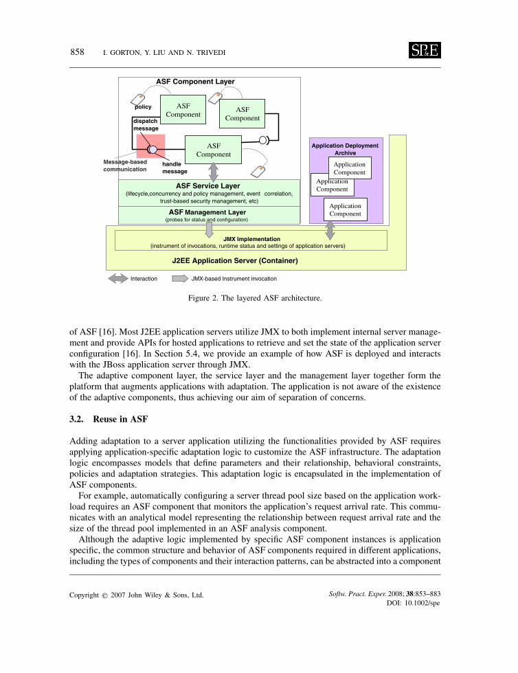
To fulfill the goals of ASF, its various components and services are designed as reusable from appli-cation to application. We divide the ASF infrastructure into three layers to address the reusabilityof its components and services. ASF executes above the middleware layer and the current imple-mentation runs on top of J2EE, as shown in Figure 2.Adaptive component layer: This layer supports a component model that defines the control
components and interactions needed to implement adaptive behaviors. The control componentscollect data on the application server’s environment, tune the server configuration and/or changeits behavior through management layer interfaces.Service layer: ASF acts as a container of control components for adaptive behaviors. In order
to manage these components, ASF provides a default implementation of useful services, such aslifecycle management, concurrent execution of ASF components, security management, and soon. The service layer provides infrastructure support for reusable ASF components services. Forexample, policies are application defined, but the mechanisms for checking and enforcing policesprovided by the policy management subsystem are generic, and therefore they can be reused asinfrastructure services. By separating these general services into a specific layer, the tasks ofdeveloping adaptive behavior using ASF control components can be further simplified.Management layer: ASF control components are executed on top of the management layer.
The management layer includes utilities and mechanisms that can be used to monitor the runtimebehavior of the application and the underlying platform, and reconfigure the application settings.Our goal is to build adaptive server applications without requiring changes to or specialized servicesfrom the underlyingmiddleware. This is achieved by utilizing standard-basedmanagement protocolsto collect status information and reconfigure an application server. For example, the J2EE JMX (JavaManagement Extensions)-based management architecture is leveraged in our J2EE implementation
Copyright q 2007 John Wiley & Sons, Ltd. Softw. Pract. Exper. 2008; 38:853–883DOI: 10.1002/spe
858 I. GORTON, Y. LIU AND N. TRIVEDI
ASF Service Layer(lifecycle,concurrency and policy management, event correlation,
trust-based security management, etc)
ASFComponent
ASFComponent
ASFComponent
Message-basedcommunication
ApplicationComponent
ApplicationComponent
ApplicationComponentASF Management Layer
(probes for status and configuration)
policy
J2EE Application Server (Container)
JMX-based Instrument invocation
Application DeploymentArchive
handlemessage
dispatchmessage
JMX Implementation(instrument of invocations, runtime status and settings of application servers)
Interaction
ASF Component Layer
Figure 2. The layered ASF architecture.
of ASF [16]. Most J2EE application servers utilize JMX to both implement internal server manage-ment and provide APIs for hosted applications to retrieve and set the state of the application serverconfiguration [16]. In Section 5.4, we provide an example of how ASF is deployed and interactswith the JBoss application server through JMX.The adaptive component layer, the service layer and the management layer together form the
platform that augments applications with adaptation. The application is not aware of the existenceof the adaptive components, thus achieving our aim of separation of concerns.
3.2. Reuse in ASF
Adding adaptation to a server application utilizing the functionalities provided by ASF requiresapplying application-specific adaptation logic to customize the ASF infrastructure. The adaptationlogic encompasses models that define parameters and their relationship, behavioral constraints,policies and adaptation strategies. This adaptation logic is encapsulated in the implementation ofASF components.For example, automatically configuring a server thread pool size based on the application work-
load requires an ASF component that monitors the application’s request arrival rate. This commu-nicates with an analytical model representing the relationship between request arrival rate and thesize of the thread pool implemented in an ASF analysis component.Although the adaptive logic implemented by specific ASF component instances is application
specific, the common structure and behavior of ASF components required in different applications,including the types of components and their interaction patterns, can be abstracted into a component
Copyright q 2007 John Wiley & Sons, Ltd. Softw. Pract. Exper. 2008; 38:853–883DOI: 10.1002/spe
AN EXTENSIBLE AND LIGHTWEIGHT ARCHITECTURE 859
framework similar to EJB and CCM. For example, a monitor component may be implementeddifferently to collect CPU status or network speed or the runtime server thread pool size. Regardless,the lifecycle methods are the same for different monitor instances.Therefore, the ASF component framework defines the types and interfaces of ASF components, as
well as their communication patterns, and the framework is reusable from application to application.Details of ASF components are described in Section 4. We will illustrate how ASF components areutilized for developing application-specific adaptation in Section 5 using a case study.
4. THE ASF COMPONENT MODEL
The kernel of ASF is the component model and its default implementation. The component modeldefines the basic types of control components, their interfaces and communication patterns. Thecommon behaviors of each type of control component are abstracted as the component interfaces.ASF provides a default implementation of components to reduce the overhead of developing themfrom scratch. Also, the component model leverages the ASF services, which further eases thedevelopment of adaptive behaviors.
4.1. Basic ASF components and interfaces
The key concepts in ASF are the components used for implementing the adaptive behaviors, forexample, monitoring an application’s runtime environment, analyzing collected data and changingthe runtime configuration. An ASF component is the basic building block in the framework, fromwhich specialized components, customized for an application, are derived.The default implementation of ASF provides component skeletons and glue for their communi-
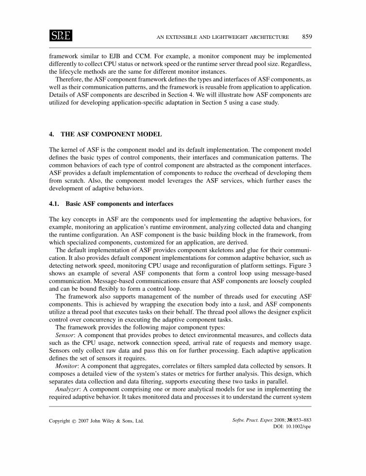
cation. It also provides default component implementations for common adaptive behavior, such asdetecting network speed, monitoring CPU usage and reconfiguration of platform settings. Figure 3shows an example of several ASF components that form a control loop using message-basedcommunication. Message-based communications ensure that ASF components are loosely coupledand can be bound flexibly to form a control loop.The framework also supports management of the number of threads used for executing ASF
components. This is achieved by wrapping the execution body into a task, and ASF componentsutilize a thread pool that executes tasks on their behalf. The thread pool allows the designer explicitcontrol over concurrency in executing the adaptive component tasks.The framework provides the following major component types:Sensor: A component that provides probes to detect environmental measures, and collects data
such as the CPU usage, network connection speed, arrival rate of requests and memory usage.Sensors only collect raw data and pass this on for further processing. Each adaptive applicationdefines the set of sensors it requires.Monitor: A component that aggregates, correlates or filters sampled data collected by sensors. It
composes a detailed view of the system’s states or metrics for further analysis. This design, whichseparates data collection and data filtering, supports executing these two tasks in parallel.Analyzer: A component comprising one or more analytical models for use in implementing the
required adaptive behavior. It takes monitored data and processes it to understand the current system
Copyright q 2007 John Wiley & Sons, Ltd. Softw. Pract. Exper. 2008; 38:853–883DOI: 10.1002/spe
860 I. GORTON, Y. LIU AND N. TRIVEDI
Sensor
Effector
Monitor Analyzer
Engine
RuleRepository
policy
PolicyManager
waiting queue
idle threads
Execution Thread Pool
Task1 Task2
dispatch task execution
lifecycle managementmessage based communication
Figure 3. An example of ASF components and communication.
state or predict possible future application states. An example is using a queuing network model toanalyze or predict the system’s throughput or resource usage.Repository: A component that stores the output of the decisions from the analyzer. These can be
reused if the same application state is encountered, reducing the analysis overhead required.Effector: A component that makes adaptive behavior occur. It changes the behavior of the server
application directly by executing a different algorithm, or indirectly by modifying the configurationsettings of the application server. It can directly accept a monitor’s instructions to effect a decisionor retrieve a decision record from the repository if the current state and resulting decision havealready been encountered and stored.Policy manager: A component that manages policies by taking input conditions, parsing the
policy descriptions and producing one resulting policy to take effect from several policies, based onthe priority of each policy. ASF currently only supports simple action-based policy reasoning [17].QueuedExecutor: A component that hosts a thread pool and an associated wait queue. An execu-
tion task for a component is dispatched to the executor. It provides a means of managing the threadsused in implementing adaptive behavior. If the number of thread execution requests exceed thecapacity of the thread pool, requests will be either queued or rejected based on a defined handlingpolicy.Engine: A component that bootstraps all other components and acts as their manager. The
engine together with other components it manages form a deployment archive dedicated to one ormultiple adaptation concerns for a specific application under management. An engine also sets themanagement boundary for ASF components. Communication between ASF components deployedin different archives is achieved through the interfaces of their enclosing engine.
Copyright q 2007 John Wiley & Sons, Ltd. Softw. Pract. Exper. 2008; 38:853–883DOI: 10.1002/spe

AN EXTENSIBLE AND LIGHTWEIGHT ARCHITECTURE 861
Figure 4. The element interface of ASF components.
Figure 5. ASF component communication.
The ASF component model also defines the interfaces and bindings of components as describedbelow:Lifecycle interface: Each ASF component also supports the Element interface (see Figure 4)
that enables the engine to determine and change the state of an element (i.e. ASF component).State management interfaces: These permit an element to expose its attribute values. Each element
is associated with an information object representing its attributes, for example, the samplingfrequency of a sensor.Message-based communication interfaces: These allow a message from a message producer
element (e.g. a sensor) to be passed asynchronously to message consumer elements (e.g. a monitor).This message-based communication pattern is illustrated in Figure 5. Message producers have thedispatchMessage()method that dispatches messages to the QueuedExecutor. The executor allocatesa thread to iterate over all associated message consumer elements and invoke their handleMessage()callback method to process the message sent to it.Concurrency interfaces: These provide a way of decoupling task submission from the mechanics
of how each task will run, including details of thread use and scheduling. The concurrency interfacesare implemented using the JDK 1.5 concurrency package. These allow synchronous invocationthrough the execute() method or asynchronous invocation through the submit() method. The default
Copyright q 2007 John Wiley & Sons, Ltd. Softw. Pract. Exper. 2008; 38:853–883DOI: 10.1002/spe
862 I. GORTON, Y. LIU AND N. TRIVEDI
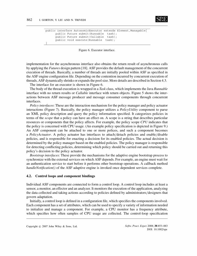
Figure 6. Executor interface.
implementation for the asynchronous interface also obtains the return result of asynchronous callsby applying the Futures design pattern [18]. ASF provides the default management of the concurrentexecution of threads. Basically, a number of threads are initially pooled within ASF as specified inthe ASF engine configuration file. Depending on the contention incurred by concurrent execution ofthreads, ASF dynamically shrinks or expands the pool size.More details are described in Section 4.3.The interface for an executor is shown in Figure 6.The body of the thread execution is wrapped in a Task class, which implements the Java Runnable
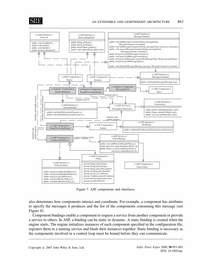
interface with no return results or Callable interface with return objects. Figure 5 shows the inter-actions between ASF message producer and message consumer components through concurrentinterfaces.Policy interfaces: These are the interaction mechanism for the policy manager and policy actuator
interactions (Figure 7). Basically, the policy manager utilizes a PolicyUtility component to parsean XML policy description and query the policy information specified. It categorizes policies interms of the scope that a policy can have an effect on. A scope is a string that describes particularresources or components that the policy affects. For example, the policy scope CPU indicates thatthe policy is concerned with CPU usage. (An example policy specification is depicted in Figure 9.)An ASF component can be attached to one or more polices, and such a component becomesa PolicyActuator. A policy actuator has interfaces to attach/detach policies and enable/disablepolicies, and is responsible for enacting a decision for its enabled policies. The actual decision isdetermined by the policy manager based on the enabled policies. The policy manager is responsiblefor detecting conflicting policies, determining which policy should be carried out and returning thispolicy’s decision to the policy actuator.Bootstrap interfaces: These provide the mechanisms for the adaptive engine bootstrap process to
synchronize with the external services on which ASF depends. For example, an engine must wait foran authentication service to start before it performs other bootstrap operations. A callback methodhandleNotification() of the ASF adaptive engine is invoked once dependent services complete.
4.2. Control loops and component bindings
Individual ASF components are connected to form a control loop. A control loop includes at least asensor, a monitor, an effector and an analyzer. It monitors the execution of the application, analyzingthe data collected and taking actions according to policies defined by administrators/designers thatgovern adaptation.Initially, a control loop is defined in a configuration file, which specifies the components involved.
Each component has a set of attributes, which can be used to specify a variety of information neededto initialize and manage a component. For example, a CPU monitor has a frequency attribute,which specifies how often samples of CPU usage are collected. The control-loop specification
Copyright q 2007 John Wiley & Sons, Ltd. Softw. Pract. Exper. 2008; 38:853–883DOI: 10.1002/spe
AN EXTENSIBLE AND LIGHTWEIGHT ARCHITECTURE 863
Figure 7. ASF components and interfaces.
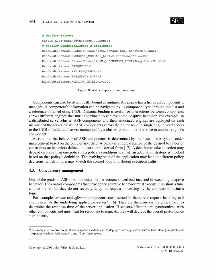
also determines how components interact and coordinate. For example, a component has attributesto specify the messages it produces and the list of the components consuming this message (seeFigure 8).Component bindings enable a component to request a service from another component or provide
a service to others. In ASF, a binding can be static or dynamic. A static binding is created when theengine starts. The engine initializes instances of each component specified in the configuration file,registers them in a naming service and binds their instances together. Static binding is necessary asthe components involved in a control loop must be bound before they can communicate.
Copyright q 2007 John Wiley & Sons, Ltd. Softw. Pract. Exper. 2008; 38:853–883DOI: 10.1002/spe
864 I. GORTON, Y. LIU AND N. TRIVEDI
Figure 8. ASF component configuration.
Components can also be dynamically bound at runtime. An engine has a list of all components itmanages. A component’s information can be navigated by its component type through this list anda reference obtained using JNDI. Dynamic binding is useful for interactions between componentsacross different engines that must coordinate to achieve some adaptive behavior. For example, ina distributed server cluster, ASF components and their associated engines are deployed on eachmember of the server cluster. ASF components across the boundary of a single engine need accessto the JNDI of individual server maintained by a cluster to obtain the reference to another engine’scomponent.At runtime, the behavior of ASF components is determined by the state of the system under
management based on the policies specified. A policy is a representation of the desired behavior orconstraints on behaviors defined in a standard external form [17]. A decision to take an action maydepend on more than one policy. If a policy’s conditions are met, an adaptation strategy is invokedbased on that policy’s definition. The evolving state of the application may lead to different policydecisions, which in turn may switch the control loop to different execution paths.
4.3. Concurrency management
One of the goals of ASF is to minimize the performance overhead incurred in executing adaptivebehavior. The control components that provide the adaptive behavior must execute in as short a timeas possible so that they do not severely delay the request processing by the application businesslogic.For example, sensor and effector components are inserted in the server request handling call
chains used by the underlying application server§ [16]. They are therefore on the critical path todetermine the response time of the server application. If sensors/effectors are synchronized withother components and must wait for responses to requests, they will degrade the overall performancesignificantly.
§For example, customized request and response handlers can be deployed into application servers that intercept requests andresponses, such as Axis handlers and JBoss interceptors.
Copyright q 2007 John Wiley & Sons, Ltd. Softw. Pract. Exper. 2008; 38:853–883DOI: 10.1002/spe
AN EXTENSIBLE AND LIGHTWEIGHT ARCHITECTURE 865
One solution is to increase the concurrency level of ASF by adding more threads. However, thereis a trade-off between concurrency and contention introduced by multi-threading. This problemis addressed in ASF by dispatching tasks asynchronously to the QueuedExecutor described inSections 4.1 and 4.2 in order to control the concurrency level and minimize delays.The implementation of QueuedExecutor provides improved performance when executing large
numbers of asynchronous tasks due to the reduced per-task invocation overhead of creating threads.The QueuedExecutor thread pool and its wait queue also smooth out any increasing demand fromthreads caused by peaks in workload in the engine by controlling the size of the thread pool. Thethread pool size is an important parameter for tuning the performance of the adaptive engine as itdirectly affects the concurrency level.The ASF architecture, with a dedicated QueuedExecutor component, represents a clear sepa-
ration of concerns in managing the multithreading of adaptive behavior. The execution tasks aredispatched to the executor, which is independent of the application server’s thread management.This provides the advantage of managing the concurrency of the adaptive engine separately. Tuningthe thread pool size for the engine can be done without interfering with the application server’ssettings.
4.4. Policy specification
An XML schema is defined to describe the policy associated with an ASF component. Basically, apolicy consists of five elements: name, scope, condition, decision and priority. The scope elementdescribes the specific scope of this policy application, and it is also used by the policy manager tocategorize policies. As ASF currently only supports action-based policy management, the conditionelement defines the condition expression with variables and operators such as greater, equal, notequal and less. The decision element is a description of the action and the actual implementation isfulfilled in ASF components. The priority (values from 1 to 10) is utilized by the policy managerto determine a policy to act on if a conflict of policies occurs.In terms of the relationship with standard policy specification, WS-Policy defines a container for
assertions, and ASF policies can be assertions contained in a WS-Policy document. Figure 9 showsa simple policy example controlling the CPU utilization: that is, if the CPU utilization is greaterthan 80%, then the action of ‘TuneConfiguration’ is to be taken, and this policy is of high prioritywith value 10.
4.5. Deployment of ASF components
ASF components need to be instantiated for a specific application and deployed into the server thatthe application runs on. ASF utilizes JMX to implement the probe for J2EE application servers.There are two ways of implementing this depending on the architecture of the application server.
One is to deploy the ASF components such as sensors and effectors as Interceptors through whichany invocation to the J2EE server passes.We have studied eight different types of middleware platforms, including Web service containers
(Axis and Axis 2), Java-based servers (JBoss and Tomcat), Grid container (Globus Toolkit 4),Enterprise Service Bus (Mule) and .Net platform (ASP.Net and Windows Communication Founda-tion (WCF)). We found that all these middleware platforms share a common structure despite thedifference in their functionalities and programming models, that is a request and a reply message
Copyright q 2007 John Wiley & Sons, Ltd. Softw. Pract. Exper. 2008; 38:853–883DOI: 10.1002/spe

866 I. GORTON, Y. LIU AND N. TRIVEDI
Figure 9. Example of policy description.
pass through an invocation chain composed of a set of interceptors. Each interceptor implementscertain functionality to service a client request, such as checking security authentication or loggingmessages. Every call processes through the chain from first to last, until finally the target servicecomponent is called. After the target is finished with its method, the call will unwind through thechain in reverse order. The code of an Interceptor looks like this:
public Object invoke( final Invocation mi) throws Exception {// Perform inbound tasks;// Call next Interceptor in the stack;lReturn = getNext().invoke( mi);// Performance outbound tasks;// Return to previous Interceptor;return lReturn;
}
This mechanism does not require any changes in the client application, which is ideal fordeploying ASF components. All the above middleware platforms allow ASF components ascustomized interceptors to be hooked in simply by changing configuration.
Copyright q 2007 John Wiley & Sons, Ltd. Softw. Pract. Exper. 2008; 38:853–883DOI: 10.1002/spe
AN EXTENSIBLE AND LIGHTWEIGHT ARCHITECTURE 867
The other way is to wrap ASF components as JMX MBeans and deploy the MBeans into theMBean server supported by the J2EE application server environment. In this case, client applicationsneed to delegate their invocations to MBeans, which redirect calls to application components. Inthis case, AOP techniques can be applied to wrap the MBeans-specific code for an applicationserver, which is then weaved into the client wherever delegation to MBeans is required. In this way,instrumentation and interception can be implemented in MBeans without changing the implemen-tation of application components. We can also separate the platform-specific porting code from theclient application implementation. In this paper, we illustrate the development and development ofASF components using interceptors.
5. CASE STUDY
When using ASF to develop customized adaptive behavior for server applications, the focus is onthe control logic design. This involves the following tasks:
1. Derive a description of the adaptive behaviors needed to meet the business goals.2. Determine the control loops for implementing the adaptive behavior. For each control loop,
the following tasks are carried out:3. Identify parameters that characterize the adaptive behavior in this control loop, along with
their dependencies.4. Devise analysis models that can represent the relationship between these parameters.5. Determine the components involved in each control loop and how they interact. Sensor and
monitor components are used to collect the values of measurable parameters, such as CPUusage and the arrival rate of requests. These values are fed into analysis models, whichare embedded in analyzer components. The output of the analyzers indicates how effectorcomponents perform adaptive behavior, such as changing the system’s configuration.
6. Implement each component using ASF. The designer extends the basic components in ASFand implements their interfaces with the control logic needed to fulfill the business goals.Designers leverage the existing services, lifecycle management and concurrency controlprovided by ASF.
7. Deploy and execute the adaptive engine.8. Test and evaluate the resulting application behavior.
Tasks 2–5 are iterative until the adaptive behavior satisfies the business goals. The processdescribed above is a general guide for developing adaptive behavior for server applications. Inthe remainder of this section, we use a case study to specifically demonstrate how to use ASF todevelop adaptive behaviors.
5.1. Adaptive image server
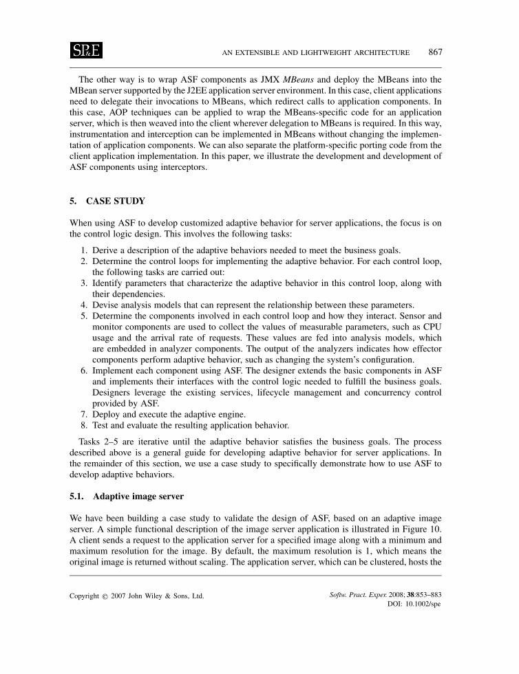
We have been building a case study to validate the design of ASF, based on an adaptive imageserver. A simple functional description of the image server application is illustrated in Figure 10.A client sends a request to the application server for a specified image along with a minimum andmaximum resolution for the image. By default, the maximum resolution is 1, which means theoriginal image is returned without scaling. The application server, which can be clustered, hosts the
Copyright q 2007 John Wiley & Sons, Ltd. Softw. Pract. Exper. 2008; 38:853–883DOI: 10.1002/spe
868 I. GORTON, Y. LIU AND N. TRIVEDI
ClientApplication
Sever Image DB
1. request a image withfile name,minimal resolution,maximum resolution
2. retrieve the imagesaved in the BLOBfield
3. scale the image
4. return the scaledimage back to client
Adaptive Control Components1. adaptation to scale images with optimized resolution2. adaptation to optimize performance
Figure 10. Image retrieval use case.
image-processing application, which sends a request to retrieve the image from a database, wherethe image is stored as a BLOB (Binary Large Object). Without adaptation, the image server scalesan image to the maximum resolution requested and returns it to the client. With adaptation, the goalis to scale the image resolution so that the overall performance of the application can be optimized.
5.2. Problem analysis
The business goals of the application are to improve the throughput and reduce the response timeof the image server. Within the range of a minimum and a maximum resolution for an imagerequested by the client, the server can choose the resolution and image quality it delivers in orderto optimize its performance. However, scaling an image takes CPU time, and the image size affectsimage transport time. Hence, this requires adaptive control logic to balance the overhead intro-duced by scaling images against the response time improvement by reducing the network latency.Quantitative performance models can therefore be used to capture the relationship between scalingimage computation cost and network latency. The development of such performance models for thisproblem and the population of their parameters are described in Appendix A. These performancemodels are subsequently embedded in the adaptive component implementation, which drives theadaptive behavior at runtime.
5.3. Developing ASF adaptive components
Improving the throughput and reducing the response time of the image server rely on two aspectsof adaptation: (1) adapting the quality and resolution of the images requested; (2) configuring theconcurrency level of request execution and adaptive control logic computation so that the CPU isnot saturated.This first adaptation trades off image resolution, quality against image-processing time and image
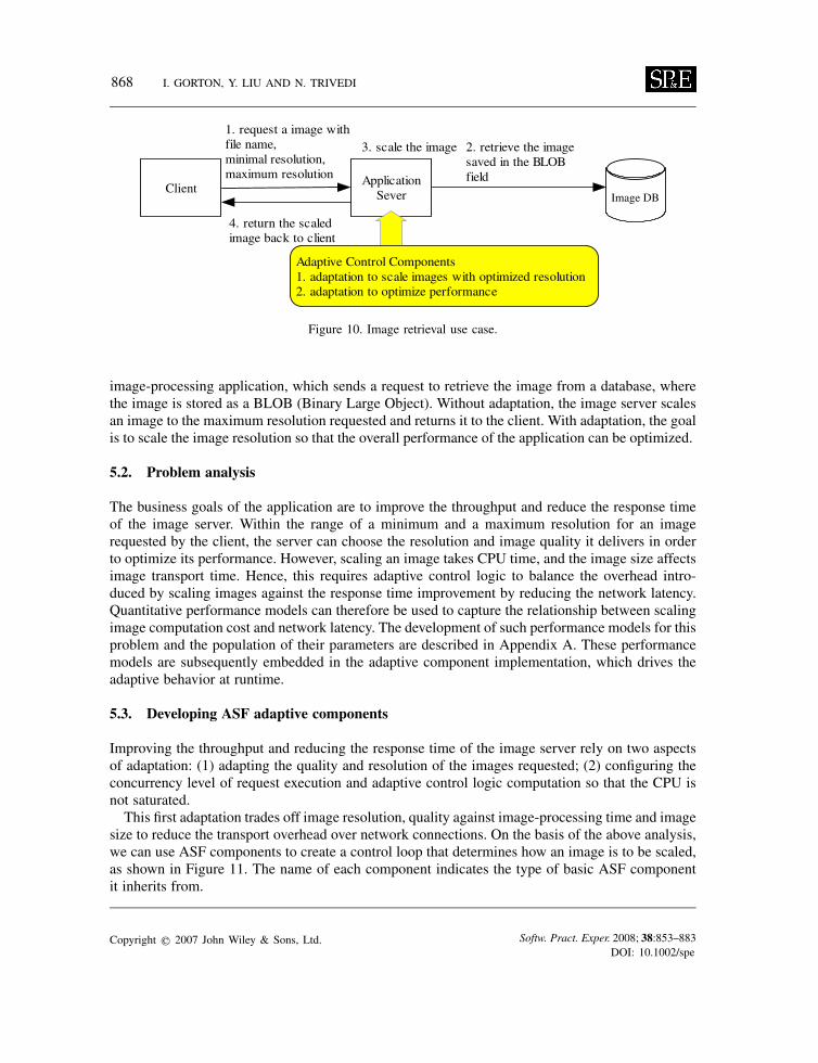
size to reduce the transport overhead over network connections. On the basis of the above analysis,we can use ASF components to create a control loop that determines how an image is to be scaled,as shown in Figure 11. The name of each component indicates the type of basic ASF componentit inherits from.
Copyright q 2007 John Wiley & Sons, Ltd. Softw. Pract. Exper. 2008; 38:853–883DOI: 10.1002/spe
AN EXTENSIBLE AND LIGHTWEIGHT ARCHITECTURE 869
Figure 11. The control loop for scaling an image.
• ImageScaleEngine is responsible for bootstrapping the adaptive engine and managing all theother elements.
• BandwidthSensor intercepts a client request and detects the client connection network speedBnetwork and request arrival rate �. It forms a message with these details and sends it to themonitor. It also assigns a unique id to each invocation to differentiate invocations from differentclients requesting the same image.
• ImageScaleMonitor takes the BandwidthSensor input message, attaches the CPU usage to themessage and sends it to the analyzer. The CPU usage is collected from the CPU sensor, whichis described below.
• ImageScaleAnalyzer implements the analysis model represented in formulas (1)–(3).• ImageScaleMetricsRepository takes the output of the ImageScaleAnalyzer and stores a recordof the resolution and quality for the image to be scaled. Each record is identified by a compoundkey with the invocation id and image file name.
• ImageScaleEffector retrieves the record from the repository. If there is no record stored, it justscales the image with the maximum resolution required by the client; otherwise it interceptsthe return method of the application’s invocation and replaces the return result with the imagescaled according to the quality and resolution analyzed.
These components interact using the asynchronous communication model described in Section 4.Figure 5 depicts an example of the communication between BandwidthSensor and the ImageScale-Monitor.For the second adaptation, the adaptive engine and server application share the underlying plat-
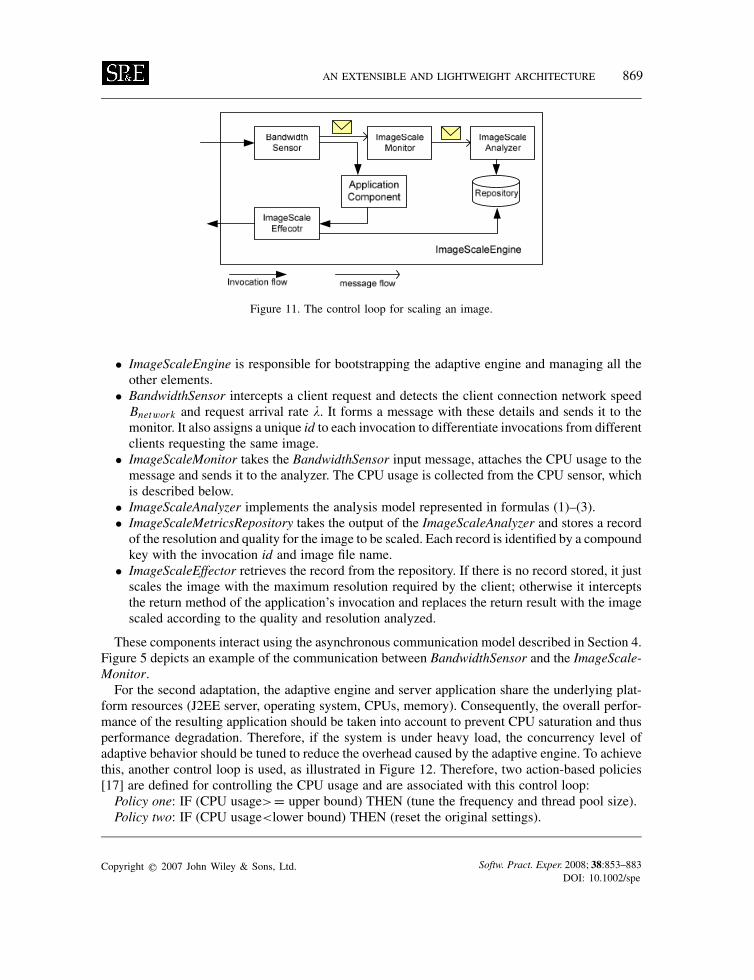
form resources (J2EE server, operating system, CPUs, memory). Consequently, the overall perfor-mance of the resulting application should be taken into account to prevent CPU saturation and thusperformance degradation. Therefore, if the system is under heavy load, the concurrency level ofadaptive behavior should be tuned to reduce the overhead caused by the adaptive engine. To achievethis, another control loop is used, as illustrated in Figure 12. Therefore, two action-based policies[17] are defined for controlling the CPU usage and are associated with this control loop:Policy one: IF (CPU usage>= upper bound) THEN (tune the frequency and thread pool size).Policy two: IF (CPU usage<lower bound) THEN (reset the original settings).
Copyright q 2007 John Wiley & Sons, Ltd. Softw. Pract. Exper. 2008; 38:853–883DOI: 10.1002/spe
870 I. GORTON, Y. LIU AND N. TRIVEDI
Figure 12. The control loop for CPU usage.
The CPUSensor detects the CPU usage for every interval. The default interval is 1 s. It sends theCPU usage samples as a message to the ConfigurationMonitor. If half of the samples during the last10 intervals exceed a configurable upper threshold of CPU usage, themonitor sends a tuningmessageto the ConfigurationEffector. Otherwise, it sends a reset message to the ConfigurationEffector¶ . TheConfigurationEffector is associated with Policies 1 and 2. It is responsible for setting the frequencyand thread pool size of the scaling engine elements when the CPU is overloaded, or for resettingthe default configuration when the CPU is below the lower bound utilization. We have developed aqueuing network model to facilitate the tuning of the thread pool size and sampling frequency. Themodel captures the relationship between overall response time, the thread pool size, the samplingfrequency and the arrival rate of requests and the CPU usage. The detailed descriptions of thismodel can be found in Appendix A.
5.4. Case study implementation
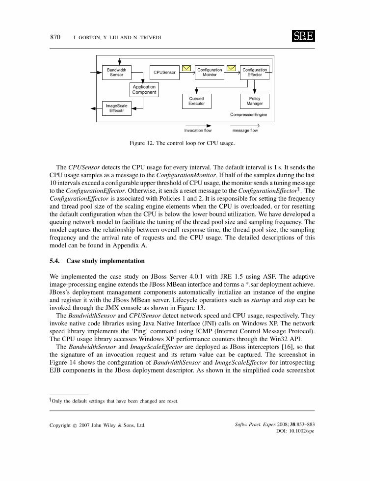
We implemented the case study on JBoss Server 4.0.1 with JRE 1.5 using ASF. The adaptiveimage-processing engine extends the JBoss MBean interface and forms a *.sar deployment achieve.JBoss’s deployment management components automatically initialize an instance of the engineand register it with the JBoss MBean server. Lifecycle operations such as startup and stop can beinvoked through the JMX console as shown in Figure 13.The BandwidthSensor and CPUSensor detect network speed and CPU usage, respectively. They
invoke native code libraries using Java Native Interface (JNI) calls on Windows XP. The networkspeed library implements the ‘Ping’ command using ICMP (Internet Control Message Protocol).The CPU usage library accesses Windows XP performance counters through the Win32 API.The BandwidthSensor and ImageScaleEffector are deployed as JBoss interceptors [16], so that
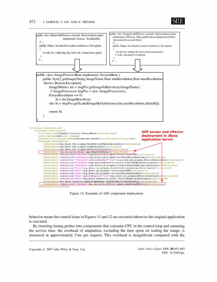
the signature of an invocation request and its return value can be captured. The screenshot inFigure 14 shows the configuration of BandwidthSensor and ImageScaleEffector for introspectingEJB components in the JBoss deployment descriptor. As shown in the simplified code screenshot
¶Only the default settings that have been changed are reset.
Copyright q 2007 John Wiley & Sons, Ltd. Softw. Pract. Exper. 2008; 38:853–883DOI: 10.1002/spe

AN EXTENSIBLE AND LIGHTWEIGHT ARCHITECTURE 871
Figure 13. JMX console for the ImageScaleEngine.
in Figure 14, the business logic of the EJB component remains unchanged. The sensor and theeffector intercept the method invocation and process the request in the body of method invoke.We also developed a timer utility with a resolution of 1ms using JNI and the Win32 API. We
use this timer to instrument the relevant operations at the beginning and at the end of the code.
5.5. Test bed setup
A Java client application simulates the workload by starting a number of threads and simultaneouslysending requests to the server. Each client randomly picks a file name as its parameter for therequest to the server, and the server component (a session EJB) returns the corresponding image asa byte stream. Our test data have images stored in an Oracle 9i database as BLOBs, with sizes from800 bytes to 2.3MB. Our lab environment supports 100Mbps Ethernet, with the throughput of anetwork connection approximately 960 kbps. The client, application server and database machinesare identical. All are workstations with Dual Intel Xeon 3.00GHz CPUs and with 3G RAM, runningWindows XP.
5.6. Evaluation
We evaluate the case study application using two methods. The first method measures the overheadof the image-scaling engine in terms of its performance and memory footprint. The second onecompares the response time with and without the adaptive behavior being enabled. Enabling adaptive
Copyright q 2007 John Wiley & Sons, Ltd. Softw. Pract. Exper. 2008; 38:853–883DOI: 10.1002/spe
872 I. GORTON, Y. LIU AND N. TRIVEDI
Figure 14. Example of ASF component deployment.
behavior means the control loops in Figures 11 and 12 are executed otherwise the original applicationis executed.By inserting timing probes into components that consume CPU in the control loop and summing
the service time, the overhead of adaptation, excluding the time spent on scaling the image, ismeasured at approximately 5ms per request. This overhead is insignificant compared with the
Copyright q 2007 John Wiley & Sons, Ltd. Softw. Pract. Exper. 2008; 38:853–883DOI: 10.1002/spe
AN EXTENSIBLE AND LIGHTWEIGHT ARCHITECTURE 873
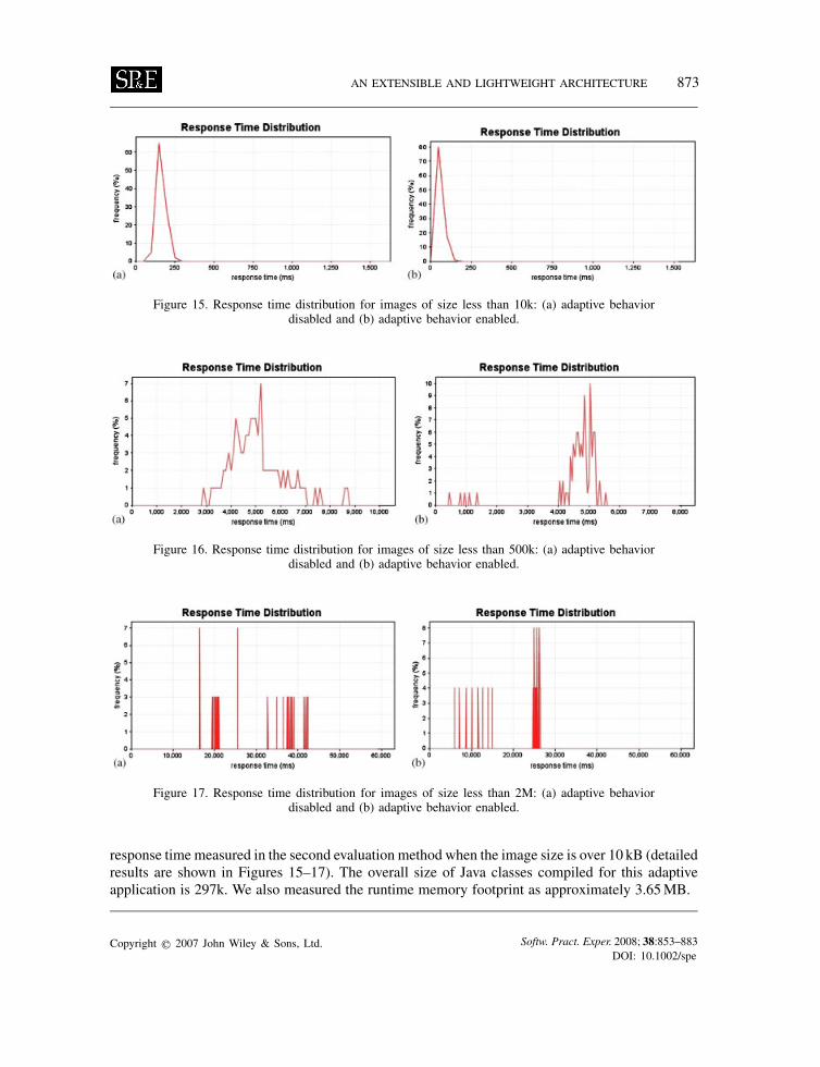
Figure 15. Response time distribution for images of size less than 10k: (a) adaptive behaviordisabled and (b) adaptive behavior enabled.
Figure 16. Response time distribution for images of size less than 500k: (a) adaptive behaviordisabled and (b) adaptive behavior enabled.
Figure 17. Response time distribution for images of size less than 2M: (a) adaptive behaviordisabled and (b) adaptive behavior enabled.
response time measured in the second evaluation method when the image size is over 10 kB (detailedresults are shown in Figures 15–17). The overall size of Java classes compiled for this adaptiveapplication is 297k. We also measured the runtime memory footprint as approximately 3.65MB.
Copyright q 2007 John Wiley & Sons, Ltd. Softw. Pract. Exper. 2008; 38:853–883DOI: 10.1002/spe
874 I. GORTON, Y. LIU AND N. TRIVEDI
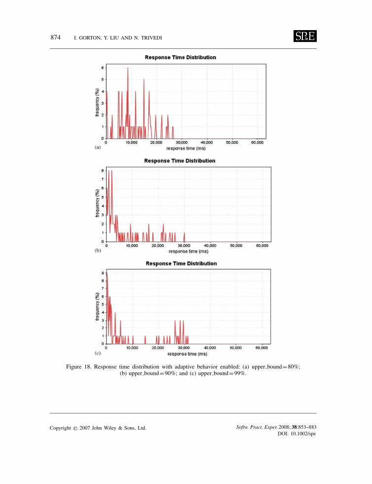
Figure 18. Response time distribution with adaptive behavior enabled: (a) upper bound=80%;(b) upper bound=90%; and (c) upper bound=99%.
Copyright q 2007 John Wiley & Sons, Ltd. Softw. Pract. Exper. 2008; 38:853–883DOI: 10.1002/spe
AN EXTENSIBLE AND LIGHTWEIGHT ARCHITECTURE 875
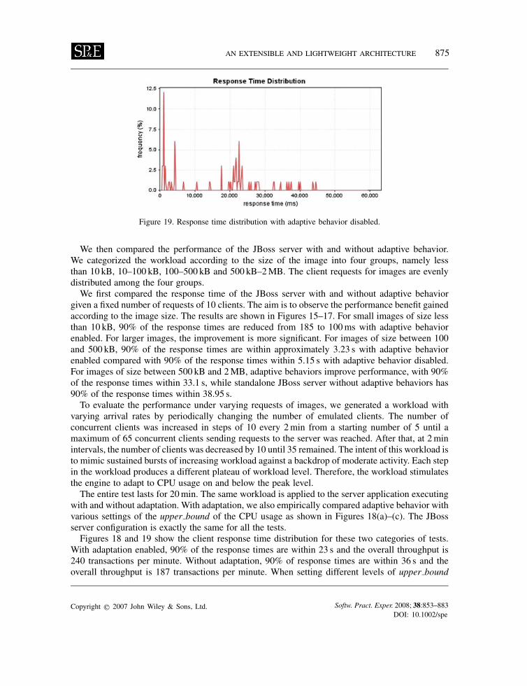
Figure 19. Response time distribution with adaptive behavior disabled.
We then compared the performance of the JBoss server with and without adaptive behavior.We categorized the workload according to the size of the image into four groups, namely lessthan 10 kB, 10–100 kB, 100–500 kB and 500 kB–2MB. The client requests for images are evenlydistributed among the four groups.We first compared the response time of the JBoss server with and without adaptive behavior
given a fixed number of requests of 10 clients. The aim is to observe the performance benefit gainedaccording to the image size. The results are shown in Figures 15–17. For small images of size lessthan 10 kB, 90% of the response times are reduced from 185 to 100ms with adaptive behaviorenabled. For larger images, the improvement is more significant. For images of size between 100and 500 kB, 90% of the response times are within approximately 3.23 s with adaptive behaviorenabled compared with 90% of the response times within 5.15 s with adaptive behavior disabled.For images of size between 500 kB and 2MB, adaptive behaviors improve performance, with 90%of the response times within 33.1 s, while standalone JBoss server without adaptive behaviors has90% of the response times within 38.95 s.To evaluate the performance under varying requests of images, we generated a workload with
varying arrival rates by periodically changing the number of emulated clients. The number ofconcurrent clients was increased in steps of 10 every 2min from a starting number of 5 until amaximum of 65 concurrent clients sending requests to the server was reached. After that, at 2minintervals, the number of clients was decreased by 10 until 35 remained. The intent of this workload isto mimic sustained bursts of increasing workload against a backdrop of moderate activity. Each stepin the workload produces a different plateau of workload level. Therefore, the workload stimulatesthe engine to adapt to CPU usage on and below the peak level.The entire test lasts for 20min. The same workload is applied to the server application executing
with and without adaptation. With adaptation, we also empirically compared adaptive behavior withvarious settings of the upper bound of the CPU usage as shown in Figures 18(a)–(c). The JBossserver configuration is exactly the same for all the tests.Figures 18 and 19 show the client response time distribution for these two categories of tests.
With adaptation enabled, 90% of the response times are within 23 s and the overall throughput is240 transactions per minute. Without adaptation, 90% of response times are within 36 s and theoverall throughput is 187 transactions per minute. When setting different levels of upper bound
Copyright q 2007 John Wiley & Sons, Ltd. Softw. Pract. Exper. 2008; 38:853–883DOI: 10.1002/spe
876 I. GORTON, Y. LIU AND N. TRIVEDI
value of the CPU usage (that is the threshold value to control the CPU utilization), we also observedvariations of the adaptive behavior in term of response time and throughput. Ninety per cent ofthe response times are within 27 (31) s and the overall throughput is 223 (201) if the value ofupper bound equals 90% (99%). An intuition is that, under the test of heavy workload, the CPUusage is most of the time over 90%, so setting it to 80% always triggers the adaptation earlier. As99% means almost saturation, the policy condition is more restful in triggering the configurationadaptation.This experimental evaluation verifies that our framework is a lightweight implementation of an
architecture that can improve the performance of server applications through adaptive behavior.
5.7. Reflection and discussion
In this case study, we have demonstrated how to use the basic ASF components and services todesign and build customized adaptive behavior. The ASF framework defines the common adaptivecomponents and their communication pattern. Once the logic of an adaptive control loop is defined,the adaptive behavior can be implemented by composing multiple components and binding themthrough message dispatch and handling interfaces. As illustrated in Figure 7, the ASF frameworksignificantly reduces the number of adaptive components that a developer needs to build fromscratch. Application-specific adaptive components inherit and customize the basic componentsprovided. The framework also includes facilities such as concurrency and policy management.Hence, by leveraging the ASF framework, a developer is able to concentrate on application-specificadaptation design and implementation.Our experience in building adaptive behavior for the image server application has provided some
insights into developing adaptive server applications:
• The adaptive logic design and implementation are driven by the application’s requirementfor adaptation. The high-level requirements need to be translated into policies that can beevaluated to produce decisions. Analytical models play a critical role in reasoning over thesystem’s behavior and in providing the necessary rules for adaptation.
• Some requirements are implicit. For example, in our case study, controlling CPU usage is notexplicit in the requirements. These implicit requirements must be identified and representedby a policy description.
• Developing adaptive applications is difficult. Designers need a programming model suchas ASF to solve many of the low-level problems of interacting with the application andperforming efficient analysis and adaptation. We believe that developing adaptive engines is aspecialized task, and hence solutions should shield application programmers from the inherentcomplexity.
6. CONCLUSION
In this paper, we present an architecture framework known as ASF for developing adaptive behaviorfor applications running on J2EE application servers. The layered ASF architecture exploits standardmanagement services, to insulate the adaptive logic implementation from the underlying appli-cation server without changing the code of either the application or the application server. Thisreduces the dependency on application server-specific features, and thus the framework is extensible
Copyright q 2007 John Wiley & Sons, Ltd. Softw. Pract. Exper. 2008; 38:853–883DOI: 10.1002/spe
AN EXTENSIBLE AND LIGHTWEIGHT ARCHITECTURE 877
and portable. The performance evaluation of the application clearly illustrates that the overheadsintroduced by ASF are low, and that performance benefits can be gained by using adaptive enginesbuilt using the framework. One contribution of this paper is the work that demonstrates that adap-tive capability can be developed with the support of architectural framework on top of existingmiddleware layers to facilitate the transparent augment of legacy applications with adaptive behav-iors. It remains our future work to integrate ASF with more comprehensive and existing policymanagement technologies.
APPENDIX A: PERFORMANCE MODEL DEVELOPMENT
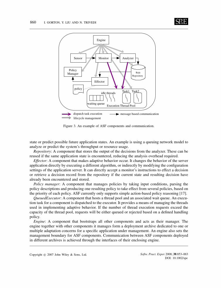
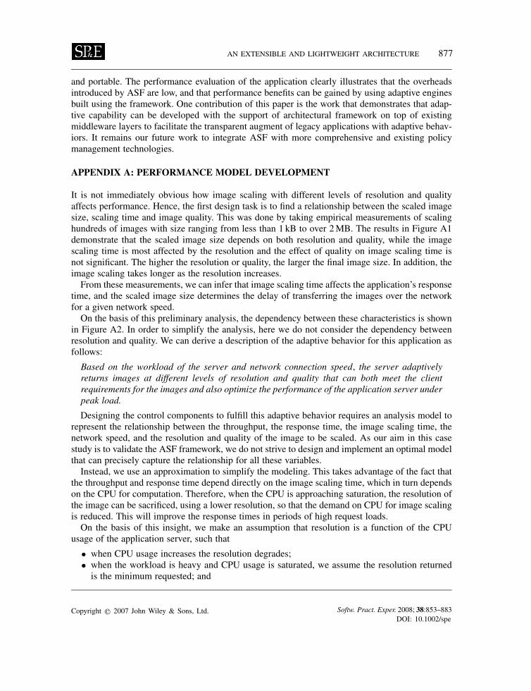
It is not immediately obvious how image scaling with different levels of resolution and qualityaffects performance. Hence, the first design task is to find a relationship between the scaled imagesize, scaling time and image quality. This was done by taking empirical measurements of scalinghundreds of images with size ranging from less than 1 kB to over 2MB. The results in Figure A1demonstrate that the scaled image size depends on both resolution and quality, while the imagescaling time is most affected by the resolution and the effect of quality on image scaling time isnot significant. The higher the resolution or quality, the larger the final image size. In addition, theimage scaling takes longer as the resolution increases.From these measurements, we can infer that image scaling time affects the application’s response
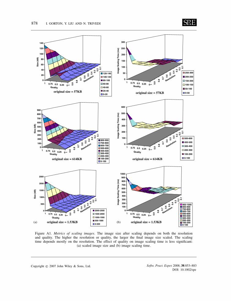
time, and the scaled image size determines the delay of transferring the images over the networkfor a given network speed.On the basis of this preliminary analysis, the dependency between these characteristics is shown
in Figure A2. In order to simplify the analysis, here we do not consider the dependency betweenresolution and quality. We can derive a description of the adaptive behavior for this application asfollows:
Based on the workload of the server and network connection speed, the server adaptivelyreturns images at different levels of resolution and quality that can both meet the clientrequirements for the images and also optimize the performance of the application server underpeak load.
Designing the control components to fulfill this adaptive behavior requires an analysis model torepresent the relationship between the throughput, the response time, the image scaling time, thenetwork speed, and the resolution and quality of the image to be scaled. As our aim in this casestudy is to validate the ASF framework, we do not strive to design and implement an optimal modelthat can precisely capture the relationship for all these variables.Instead, we use an approximation to simplify the modeling. This takes advantage of the fact that
the throughput and response time depend directly on the image scaling time, which in turn dependson the CPU for computation. Therefore, when the CPU is approaching saturation, the resolution ofthe image can be sacrificed, using a lower resolution, so that the demand on CPU for image scalingis reduced. This will improve the response times in periods of high request loads.On the basis of this insight, we make an assumption that resolution is a function of the CPU
usage of the application server, such that
• when CPU usage increases the resolution degrades;• when the workload is heavy and CPU usage is saturated, we assume the resolution returned
is the minimum requested; and
Copyright q 2007 John Wiley & Sons, Ltd. Softw. Pract. Exper. 2008; 38:853–883DOI: 10.1002/spe
878 I. GORTON, Y. LIU AND N. TRIVEDI
1 0.75 0.5 0.25 0 1 0.9 0.
8 0.7 0.
6 0.5 0.
4 0.3 0.
2 0.1
0
20
40
60
80
100
120
140
Siz
e (k
B)
Siz
e (k
B)
Siz
e (k
B)
Quality
Quality
Quality Quality
Quality
120-140
100-120
80-100
60-80
40-60
20-40
0-20original size = 57KB original size = 57KB
original size = 614KBoriginal size = 614KB
original size = 1.53KB original size = 1.53KB
1 0.75 0.5 0.25 0 1 0.9 0.
8 0.7 0.
6 0.5 0.
4 0.3 0.
2 0.1
0
500
1000
1500
2000
2500
2000-2500
1500-2000
1000-1500
500-1000
0-500
1 0.75 0.5 0.25 0 1 0.9 0.
8 0.7 0.
6 0.5 0.
4 0.3 0.
2 0.1
0
100
200
300
400
500
600
700
800
900
800-900700-800600-700500-600400-500300-400200-300100-2000-100
1 0.75 0.5 0.25 0 1 0.9 0.
8 0.7 0.
6 0.5 0.
4 0.3 0.
2 0.1
0
50
100
150
200
250
300
Imag
e S
calin
g T
ime
(ms)
250-300
200-250
150-200
100-150
50-100
0-50
1 0.75 0.5 0.25 0 1 0.9 0.
8 0.7 0.
6 0.5 0.
4 0.3 0.
2 0.1
0
100
200
300
400
500
600
700
800
900
1000
Imag
e S
calin
g T
ime
(ms)
Imag
e S
calin
g T
ime
(ms)
900-1000800-900700-800600-700500-600400-500300-400200-300100-2000-100
1 0.75 0.5 0.25 0 1 0.9 0.
8 0.7 0.
6 0.5 0.
4 0.3 0.
2 0.1
0
100
200
300
400
500
600
500-600
400-500
300-400
200-300
100-200
0-100
Resolution
Resolution
Resolution
Resolution
Resolution
Quality
Resolution
(a) (b)
Figure A1. Metrics of scaling images. The image size after scaling depends on both the resolutionand quality. The higher the resolution or quality, the larger the final image size scaled. The scalingtime depends mostly on the resolution. The effect of quality on image scaling time is less significant:
(a) scaled image size and (b) image scaling time.
Copyright q 2007 John Wiley & Sons, Ltd. Softw. Pract. Exper. 2008; 38:853–883DOI: 10.1002/spe
AN EXTENSIBLE AND LIGHTWEIGHT ARCHITECTURE 879
Throughput Response Time
Image Size
Image Scaling Time
Resolution Quality
Network Delay
Throughput Response Time
Image Size
CPU usage
Resolution Quality
Network Delay
approximation
Figure A2. The metric dependencies.
Y=EXP(-aX), a=0.6931
0
0.1
0.20.3
0.4
0.5
0.6
0.70.8
0.91
0 0.1 0.2 0.3 0.4 0.5 0.6 0.7 0.8 0.9 1CPU usage (Xcpu)
Res
olu
tio
n (
Yr)
Figure A3. A simple model for CPU usage and resolution.
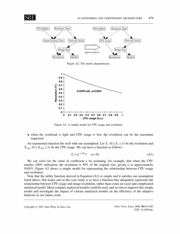
• when the workload is light and CPU usage is low, the resolution can be the maximumrequested.
An exponential function fits well with our assumption. Let Yr (0≤Yr ≤1) be the resolution andXcpu (0≤ Xcpu ≤1) be the CPU usage. We can have a function as follows:
Yr =e−aXcpu (a>0) (A1)
We can solve for the value of coefficient a by assuming, for example, that when the CPUreaches 100% utilization, the resolution is 50% of the original size, giving a as approximately0.6931. Figure A3 shows a simple model for representing the relationship between CPU usageand resolution.Note that the utility function derived in Equation (A1) is simple and it satisfies our assumption
listed above. Our major aim in this case study is to have a function that adequately represents therelationship between CPU usage and image resolution, rather than create an exact and complicatedanalytical model. More complex analytical models could be used, and we aim to improve this simplemodel and investigate the impact of various analytical models on the efficiency of the adaptivebehavior in our future work.
Copyright q 2007 John Wiley & Sons, Ltd. Softw. Pract. Exper. 2008; 38:853–883DOI: 10.1002/spe

880 I. GORTON, Y. LIU AND N. TRIVEDI
Yq=EXP(bXnet)+k, b=0.4054, k=-0.75
00.10.20.30.40.50.60.70.80.9
1
0 0.1 0.2 0.3 0.4 0.5 0.6 0.7 0.8 0.9 1Network Speed in MB (Xnet)
Qu
alit
y (Y
)
Figure A4. A model for network speed and quality.
In order to satisfy a client’s resolution requirement, the actual resolution Y used is determined as
Y =Ymin if Yr<Ymin or Y =Ymax if Yr>Ymax (A2)
where Ymin and Ymax represent minimum and maximum resolution specified by the client requests.After we determine the resolution of an image, we can use a similar approach to model the
relationship between quality (Yq ,0≤Yq ≤1) and network speed (Xnet ) in Equation (A3). The higherthe network connection speed, the higher the quality image can be delivered:
Yq =ebXnet +k (b>0) (A3)
According to the specification of the JDK AWT image scaling API, quality values of 0.75, 0.5and 0.25 roughly mean high, middle and low quality, respectively. We assume if the network isslow then the quality is set to the low value (0.25), while for fast network speed such as 1Mbps thequality is set to the high value (0.75). We can solve for the coefficients b and k and have a simplefunction shown in Figure A4.
A.1. Determining the frequency and concurrency levels
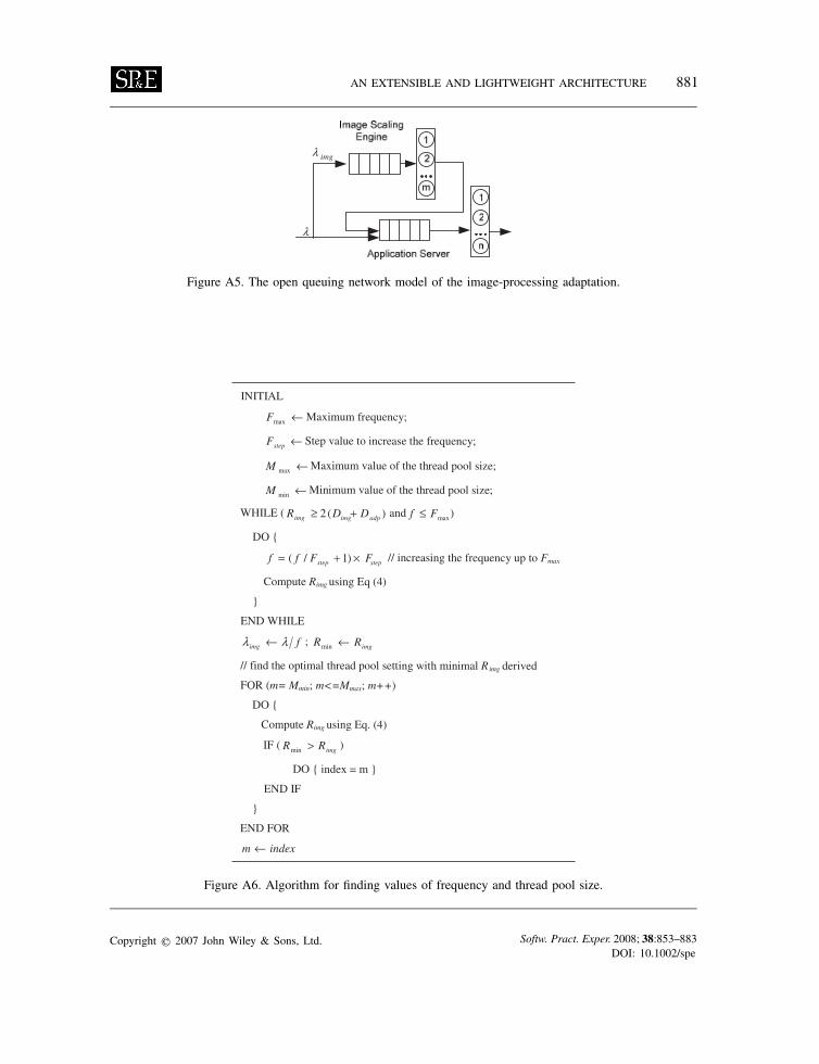
The computing cycles used by the image-processing engine and the application server are majorsources of CPU cycle consumption. They can be modeled in a simple open queueing network modelwith two load-independent multiple servers, one for the image-processing engine and the other forthe application server. In Figure A5, m and n represent the thread pool size of each, respectively,� and �img represent the request arrival rate at the application server and the image-processingengine, respectively. �img depends on the sampling frequency f ; for example, f =1 means doingadaption for every client request, and f =3 means sampling every third client request:
�img =�/ f (A4)
Copyright q 2007 John Wiley & Sons, Ltd. Softw. Pract. Exper. 2008; 38:853–883DOI: 10.1002/spe
AN EXTENSIBLE AND LIGHTWEIGHT ARCHITECTURE 881
imgλ
λ
Figure A5. The open queuing network model of the image-processing adaptation.
Figure A6. Algorithm for finding values of frequency and thread pool size.
Copyright q 2007 John Wiley & Sons, Ltd. Softw. Pract. Exper. 2008; 38:853–883DOI: 10.1002/spe
882 I. GORTON, Y. LIU AND N. TRIVEDI
Applying the MVA algorithm for an open queuing network model [14], we can derive the CPUutilization and response time of the compression engine as follows:
Uimg = �img(Dimg+Dadp) (A5)
Rimg = (Dimg+Dadp)/m
1−�img×(Dimg+Dadp)/m+ (m−1)(Dimg+Dadp)
m(A6)
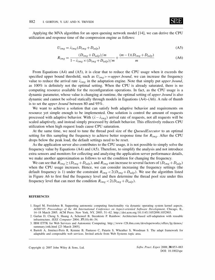
From Equations (A4) and (A5), it is clear that to reduce the CPU usage when it exceeds thespecified upper bound threshold, such as Uimg>=upper bound, we can increase the frequencyvalue to reduce the arrival rate �img in the adaptation engine. Note that simply put upper bound,as 100% is definitely not the optimal setting. When the CPU is already saturated, there is nocomputing resource available for the reconfiguration operations. In fact, as the CPU usage is adynamic parameter, whose value is changing at runtime, the optimal setting of upper bound is alsodynamic and cannot be solved statically through models in Equations (A4)–(A6). A rule of thumbis to set the upper bound between 80 and 95%.We want to achieve a solution that can satisfy both adaptive behavior and requirements on
resource yet simple enough to be implemented. One solution is control the amount of requestsprocessed with adaptive behavior. With (�−�img) arrival rate of requests, not all requests will bescaled adaptively, and instead simply processed by default behavior. This effectively reduces CPUutilization when high request loads cause CPU saturation.At the same time, we need to tune the thread pool size of the QueuedExecutor to an optimal
setting for this sampling the frequency to achieve better response time for Rimg . After the CPUdrops below the peak load, the default settings need to be reset.As the application server also contributes to the CPU usage, it is not possible to simply solve the
frequency value by Equations (A4) and (A5). Therefore, to simplify the analysis and not introduceextra sensors and monitors for collecting and analyzing the application server performance details,we make another approximation as follows to set the condition for changing the frequency.We can see that Rimg ≥(Dimg+Dadp), and Rimg can increase to several factors of (Dimg+Dadp)
when the CPU usage increases. Hence, we can consider increasing the frequency settings (thedefault frequency is 1) under the constraint Rimg <2(Dimg+Dadp). We use the algorithm listedin Figure A6 to first find the frequency level and then determine the thread pool size under thisfrequency level that can meet the condition Rimg <2(Dimg+Dadp).
REFERENCES
1. Engel M, Freisleben B. Supporting autonomic computing functionality via dynamic operating system kernel aspects.AOSD’05: Proceedings of the 4th International Conference on Aspect-oriented Software Development, Chicago, IL,14–18 March 2005. ACM Press: New York, NY, 2005; 51–62. http://doi.acm.org/10.1145/1052898.1052903.
2. Garlan D, Cheng S, Huang A, Schemerl B, Steenkiste P. Rainbow: Architecture-based self-adaptation with reusableinfrastructure. IEEE Computer 2004; 37(10):46–54.
3. IBM ETTK for Web Services and Autonomic Computing. http://www-128.ibm.com/developerworks/offers/lp/demos/summary/ettk.html [23 March 2005].
4. Bartoli A, Jimenez-Peris R, Kemme B, Pautasso C, Patarin S, Wheather S, Woodman S. The adapt framework foradaptable and composable web services. Invited article from Web Systems topic area.
Copyright q 2007 John Wiley & Sons, Ltd. Softw. Pract. Exper. 2008; 38:853–883DOI: 10.1002/spe
AN EXTENSIBLE AND LIGHTWEIGHT ARCHITECTURE 883
5. Staehli R, Eliassen F, Amundsen S. Designing adaptive middleware for reuse. In Proceedings of the 3rd Workshopon Adaptive and Reflective Middleware, ARM ’04, Toronto, Ontario, Canada, 19 October 2004, vol. 80. ACM Press:New York, NY, 2004; 189–194.
6. Gorton I, Liu A, Brebner P. Rigorous evaluation of COTS middleware technology. IEEE Computer 2003; 36(3):50–55.7. Hallsteinsen S, Floch J, Stav E. A middleware centric approach to building self-adapting systems. Software Engineering
and Middleware (Lecture Notes in Computer Science, vol. 3437). Springer: Berlin, 2004; 107–122.8. Chess DM, Segal A, Whalley I. Unity: Experiences with a prototype autonomic computing system. In Proceedings of
the First International Conference on Autonomic Computing (Icac’04) – Volume 00, 17–18 May 2004. IEEE ComputerSociety: Washington, DC, 2004; 140–147.
9. Floch J, Hallsteinsen S, Stav E, Eliassen F, Lund K, Gjorven E. Using architecture models for runtime adaptability.IEEE Softwares 2006; 23(2):62–70.
10. Grace P, Coulson G, Blair GS, Porter B. Deep middleware for the divergent grid. Proceedings of IFIP/ACM/USENIXMiddleware 2005, Grenoble, France, November 2005.
11. Kon F, Roman M, Liu P, Mao J, Yamane T, Magalhaes LC, Campbell R. Monitoring, security, and dynamic configurationwith the dynamicTAO reflective ORB. IFIP/ACM International Conference on Distributed Systems Platforms and OpenDistributed Processing, New York, 3–7 April 2000.
12. Kon F, Costa F, Campbell R, Blair G. The case for reflective middleware. Communications of the ACM 2002; 45(6):33–38.13. Abdellatif T. Enhancing the management of a J2EE application server using a component-based architecture. In
Proceedings of the 31st EUROMICRO Conference on Software Engineering and Advanced Applications – Volume 00,30 August – 3 September 2005. IEEE Computer Society: Washington, DC, 2005; 70–79.
14. Menasce DA. Performance by Design. Prentice-Hall: Englewood Cliffs, NJ, 2004, ISBN 0-13-090673-5.15. Wildstrom J, Stone P, Witchel E, Monney RJ, Dahlin M. Improve performance with self-configuring distributed systems.
17 IBM developerWorks, 2005. http://www128.ibm.com/developerworks/autonomic/library/ac-selfhw/ [6 December2005].
16. Java Management Extensions (JMX) Specification. http://jcp.org/aboutJava/communityprocess/final/jsr003/index.html[March 2004].
17. Kephart JO, Walsh W. An artificial intelligence perspective on autonomic computing polices. IEEE 5th InternationalWorkshop on Policies for Distributed Systems and Networks 2004; 3–12.
18. Lea D. Concurrent Programming in Java: Design Principles and Patterns (2nd edn). Addison-Wesley: Reading, MA,1999.
Copyright q 2007 John Wiley & Sons, Ltd. Softw. Pract. Exper. 2008; 38:853–883DOI: 10.1002/spe