an infrastructure for c/atlas environments with object-oriented design and xml representation
TRANSCRIPT
Case study: An infrastructure for C/ATLASenvironments with object-oriented design and XML
representation
Cheng-Wei Chen, Jenq Kuen Lee∗
Department of Computer Science, National Tsing-Hua University, Hsinchu, Taiwan
Abstract
In this paper, we present an ATLAS compiler environment used for automatic testing asa case study to demonstrate the design of the state of the art compiler environments withobject-oriented designs and XML representations. ATLAS is a testing language which isapplied on the automatic test equipments (ATE). Currently, the programming language isused in the fields of avionics, industry facilities, and precision transport system. In thiswork, we develop the ATLAS compiler aiming to provide the control ability of the PC-based ATEs. First, it comes with an objected-oriented representation of program trees. Theobject-oriented program graph allows the flexibility for the manipulations of program trees.Second, it employs the object serialization technology for storing and retrieving the syn-tax trees and program graphs. The employment of object serialization techniques signifi-cantly reduces the programming effort from traditional compiler work in retrieving binaryrepresentations of program graphs from secondary storages. In addition, we establish theconnection between the object-oriented program graph and XML representations. With thesupport of DTD and XSL files of XML environments, we can perform machine validationon XML-based representations, transform XML representations into graph structures, andannotate the representations for human browsing. Our software infrastructure can be usedfor subsequent controls and specifications for ATEs.
Key words: ATLAS language, compiler design, object-oriented infrastructures, automatictest equipment, XML
∗ This paper is submitted to Journal of System and Software. This is the revised version.Corresponding author. Tel.: +886-3-5715131 EXT. 3519; fax: +886-3-5723694.
Email addresses:[email protected] (Cheng-Wei Chen),[email protected] (Jenq Kuen Lee).
Preprint submitted to Elsevier Science 30 July 2002
1 Introduction
ATLAS is an IEEE Standard Test Language for All Systems (IEEE, 1998, 1995).This language is designed to describe tests in terms that are independent of anyspecific test system, and has been constrained to ensure that it can be implementedon ATE. Since the 1960’s through different phases of evolutions, it has been inuse for field maintenance of avionics for the military and for commercial airlines.Initially a test description language, it has been automated to provide for automatictest programs. It is a large language, and the development of compilers for it is nota simple task.
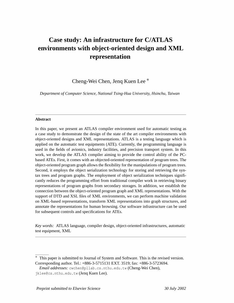
The ATE can be applied to overhaul the failure facilities on the manufacture andthe maintenance of variant precision instruments. In the process, it substantially im-proves the reliability of precision instruments. By using the ATE, the failed pointsof the failure facilities can be precisely located. Furthermore, they can be fixedin module level instead of replacement of entire systems. Therefore, the costs ofthe maintenance can be substantially decreased. The ATLAS language is widelyused on the testing process of the ATE. Figure 1 illustrates the key componentsin the ATLAS testing model. The ATLAS programs are written to provide the en-tire test steps, the requirements of the switches and connections, the requests ofthe resource, and the statistic information. The intermediate form generated in thecompiler environment is then used to generate subsequent controls to be integratedwith ATEs.
In this paper, we developed the ATLAS compiler to aim at providing the controlability of the PC-based ATEs. To achieve this goal, we developed the compiler withthe full implementation of IEEE standard. Our work is also a joint work betweenour programming language laboratory (Chang et al., 2001; Hwang et al., 1998,2001), Tsing-Hua Univ., Taiwan, and a local industrial research institute, aerospacedivision, III (Institute for Information Industry), in promoting academic compilertechnologies for industrial applications. Once the intermediate form is generatedby our compiler environment, research engineers at III then use this informationto generate controls to work with ATEs as shown in Figure 1. Our work can alsoserve as a case study to demonstrate the design of the state of the art compiler envi-ronments with object-oriented designs and XML representations. Our compiler isimplemented using object-oriented support. First, abstract syntax trees are treatedas linked objects. Linguistic constructs are defined in a class hierarchy. Object-oriented frameworks (Chang et al., 1997; Gannon and Lee, 1992; Lee et al., 1997;Wilson et al., 1994; Wu and Lee, 2000) for compiler infrastructures have gotten mo-mentum recently. Our framework employs object hierarchies to represent programgraphs of ATLAS languages. It’s also the first object-oriented design for ATLAScompiler frameworks, and we think our experiences in the ATLAS software envi-ronments should offer software experiences and interesting engineering aspects forthis problem. Second, in our design, we employ the object serialization technology
2
resource requirementresource requirement
global variable declarationglobal variable declaration
unprocessed dataunprocessed data
subroutine defi nitionsubroutine defi nition
error report (file name, line number, information)
error report (file name, line number, information)
test steptest step
switching/i nterconnectrequirement
switching/i nterconnectrequirement
statistics/report log (# ofstatements processed, # of
unprocessed statements, etc.)
statistics/report log (# ofstatements processed, # of
unprocessed statements, etc.)
IEEE Std-7161995 ATLAS
Source Program Intermediatedata
lexer/parser
Codegenerator
ATL AS Translator
Fig. 1. Key components in the ATLAS testing model.
for storing and retrieving syntax trees and program graphs. The employment ofobject serialization techniques significantly reduces the programming effort fromtraditional compiler work. Traditionally, in retrieving binary representations of pro-gram graphs from secondary storages, one needs to carefully pack binary numberand byte orders. This is normally an error-prone work. Our work is possible due toour employment of object-oriented representations of compiler intermediate forms,and our employment of emerging serialization methodologies in OO community.
Finally, we establish the connection between the object-oriented program graphand XML representations. With the support of DTD and XSL files of XML en-vironments, we can perform machine validation on XML-based representations,transform XML representations into graph structures, and annotate the representa-tions for human browsing. This connection provides great flexibilities for ATLASprogram trees to be operated under XML tools. We also report experimental resultsfor our system. Our work presents the first-hand software experiences for the stateof the art design and implementation of a complex application domain languagewith object-oriented designs and XML representations.
The remainder of this paper is organized as follows. Section 2 gives a brief descrip-tion of the ATLAS language. In Section 3, we present the development process ofthe ATLAS compiler. Section 4 then describes the XML representations for pro-gram graphs. Next, Section 5 gives our experimental results. Finally, Section 6concludes this work.
3
2 The ATLAS language and environment
2.1 Overview of ATLAS language
The increasing complexity of systems being developed in the 1960s placed con-siderable demands on testing processes. A great deal of testing needs to be done,not only in development but also as part of subsequence maintenance. The ATLASlanguage arose from the perceived need to improve the precision and efficiency ofthe process.
To respond the requests of the commercial airlines, Aeronautical Radio Incorpo-rated (ARINC) started the development of a standard testing language. There are anumber of common test procedures to test and repair similar or identical avionicssystems on the commercial aircraft, so developing test procedures in a standardizedand unambiguous way enable their efficient reuse across airlines. The name of thelanguage developed under the auspices of ARINC was the Abbreviated Test Lan-guage for Avionics Systems or ATLAS. There were a large number of commercialcompanies interested in avionics testing, and they participated in developing theATLAS language. In 1976, standardization controls for ATLAS were transferredfrom ARINC to the IEEE. At this time the name of ATLAS became the AbbreviatedTest Language for All Systems to reflect the wide-ranging nature of applications.
The ATLAS language standard was first published in 1968 and was titled ARINC416-1. In 1988 the IEEE published ATLAS standard 716-1988, which representeda subset of the ATLAS 416. In 1984 the IEEE also published standard 771. Thisstandard is a guide to the use of the ATLAS language. The up-to-date standard wasIEEE Std 716-1995.
An example of the ATLAS test program is shown in Figure 2. ATLAS program be-gins with aBEGIN ATLAS PROGRAM statement and finishes with aTERMINATEstatement. Note that each statement is started with a line-number, and the lead-ing ’E’ of the line-numberE500100 means that the statement is the beginning ofthe main program. Similar to other programming languages, the ATLAS languageprovides the declaration statements for variables (e.g. line-number000110), user-defined data types, function and procedure definitions, calculations of expressions(e.g. line-number500112), program flow control statements (e.g. TheIF-THEN-ELSE statement in line-number500140), and input and output statements for trans-ferring program data to and from an ATLAS program via consoles and/or files (e.g.line-number500110), etc.
In addition to the common program statements, the ATLAS language provides ad-ditional statements performing the test procedure. It includes declarations of con-nections (e.g. line-number000130), test resource allocation (REQUIRE statement)to establish and label test resource characteristics, theAPPLY statement generating
4

000100 BEGIN, ATLAS PROGRAM ’LAB1, PART 3’ $000110 DECLARE, VARIABLE, ’RESULTS’ IS DECIMAL$000120 DECLARE, VARIABLE, ’A’ IS INTEGER $000130 DECLARE, VARIABLE, ’HI-PIN’ IS ARRAY (1 THRU 2) OF CONNECTION
(J1-3, J1-4) INITIAL = CONNECTION J1-3, CONNECTION J1-4 $E500100 APPLY, DC SIGNAL, VOLTAGE 5 V, CNX HI ’HI-PIN’(2) LO J1-11 $
500110 OUTPUT, C’WAITING FOR 30 SEC FOR INPUT POWER STABILIZATION’,C’\LF\’ $500112 CALCULATE, ’A’ = 30 $500115 WAIT FOR, ’A’ SEC $500120 APPLY, AC SIGNAL, VOLTAGE 5 V, FREQ 60 HZ,
CNX HI ’HI-PIN’(1) LO J1-10 $500130 VERIFY, (VOLTAGE INTO ’RESULTS’), AC SIGNAL,
NOM 25.2 V UL 26.7 V LL 23.7 V,VOLTAGE RANGE 20 V TO 30 V,CNX HI J1-22 LO EARTH $
500140 IF, GO, THEN $500150 OUTPUT, C’UUT PASSED’ $500160 ELSE $500170 OUTPUT, C’UUT FAILED’ $500180 END, IF $500190 WAIT FOR, 10 SEC $500200 VERIFY, (VOLTAGE INTO ’RESULTS’), AC SIGNAL,
NOM 25.2 V UL 26.7 V LL 23.7 V,VOLTAGE RANGE 20 V TO 30 V,CNX HI J1-22 LO EARTH $
500210 IF, GO, THEN $500220 OUTPUT, C’UUT PASSED’ $500230 ELSE $500240 OUTPUT, C’UUT FAILED’ $500250 END, IF $500260 REMOVE, ALL $999999 TERMINATE, ATLAS PROGRAM $
Fig. 2. An example of the ATLAS test program, note that the leading’E’ of the line-numberE500100 means that the statement is the beginning of the main program.
or receiving a signal and defining the signal path between the UUT and the device(e.g. line-number500120), theVERIFY statement to measure and compare with thevalues of UUT (e.g. line-number500130), theREMOVE statement to remove par-ticular established connections (e.g. line-number500260 removing all establishedconnections), etc.
2.2 Objectives of our ATLAS environment
In the following, we give the key objectives in our design of ATLAS compiler envi-ronments. We also give brief descriptions of our solutions to meet these objectives.
(1) To support ATLAS compiler with IEEE Std 716-1995 specification:In this work, we develop the ATLAS compiler to aim at providing the con-
trol ability of the PC-based ATEs. To achieve this goal, we develop the com-piler with the full implementation of IEEE standard.
(2) To provide an ATLAS environment for ATE environments:ATLAS program graphs are needed to generate subsequent controls to be
integrated with ATEs. We need a program graph designed with good method-
5
ologies to provide a systematic way for the manipulations of program trees.In our design, we employ object hierarchies to represent program graphs ofATLAS languages.
(3) To establish connections between our program graph representations andXML tools:
Due to large number of keywords and command constructs in ATLAS lan-guages, we also need viewing tools for developers to manipulate the ATLASprogram graph. In our design, we establish the connection between the object-oriented program graph and XML representations. With the support of DTDand XSL files of XML environments, we can perform machine validation onXML-based representations, map XML representations into graph structures,and annotate the program representations for human browsing. This connec-tion allows ATLAS program trees to be operated under XML tools.
(4) To support optimizations of program graph storage:To reduce the size of storage of program graphs in stores, we will hope to
store the program graphs in binary representations. In our design, we employthe object serialization technology to achieve our goal for storing and retriev-ing the syntax trees and program graphs with binary representations.
3 The development of the C/ATLAS compiler
We now give the design steps for ATLAS compiler environments. These steps in-clude transforming EBNF grammars into Yacc-format grammars, class hierarchiesof program graphs, and object serializations of program graphs.
3.1 Lexical analyzer and grammars
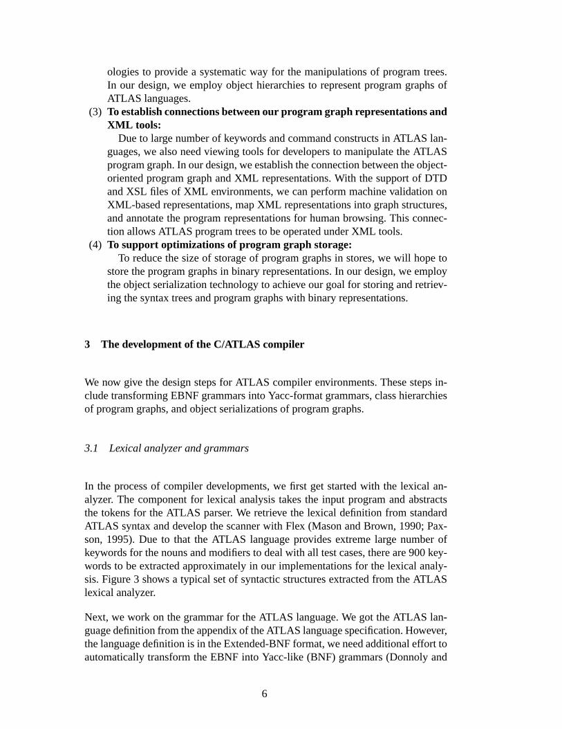
In the process of compiler developments, we first get started with the lexical an-alyzer. The component for lexical analysis takes the input program and abstractsthe tokens for the ATLAS parser. We retrieve the lexical definition from standardATLAS syntax and develop the scanner with Flex (Mason and Brown, 1990; Pax-son, 1995). Due to that the ATLAS language provides extreme large number ofkeywords for the nouns and modifiers to deal with all test cases, there are 900 key-words to be extracted approximately in our implementations for the lexical analy-sis. Figure 3 shows a typical set of syntactic structures extracted from the ATLASlexical analyzer.
Next, we work on the grammar for the ATLAS language. We got the ATLAS lan-guage definition from the appendix of the ATLAS language specification. However,the language definition is in the Extended-BNF format, we need additional effort toautomatically transform the EBNF into Yacc-like (BNF) grammars (Donnoly and
6
E500000 APPLY, DC SIGNAL USING 'DCP-1', VOLTAGE 10 V, CNX HI 'HI-CONN-LIST' LO J1-9 $
fstatno
token
labelinteger-number
connectionfd
statement-terminator
Fig. 3. The syntactic structures extracted from our ATLAS lexical analyzer.
Table 1The operators and their meanings in the Extended-BNF syntax
Operator Meaning SYNTAX-RULES Beginning of description FINIS End of description : Definition * Repetition 0 or more times % Repetition 1 or more times | Alternation # Separation + Optional chaining { } Grouping braces [] Optionality brackets ; End of rule ! Comment-indicator
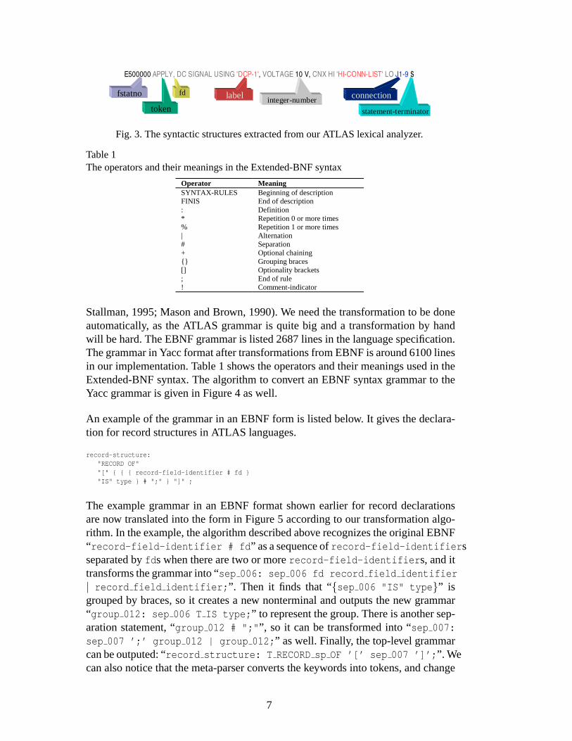
Stallman, 1995; Mason and Brown, 1990). We need the transformation to be doneautomatically, as the ATLAS grammar is quite big and a transformation by handwill be hard. The EBNF grammar is listed 2687 lines in the language specification.The grammar in Yacc format after transformations from EBNF is around 6100 linesin our implementation. Table 1 shows the operators and their meanings used in theExtended-BNF syntax. The algorithm to convert an EBNF syntax grammar to theYacc grammar is given in Figure 4 as well.
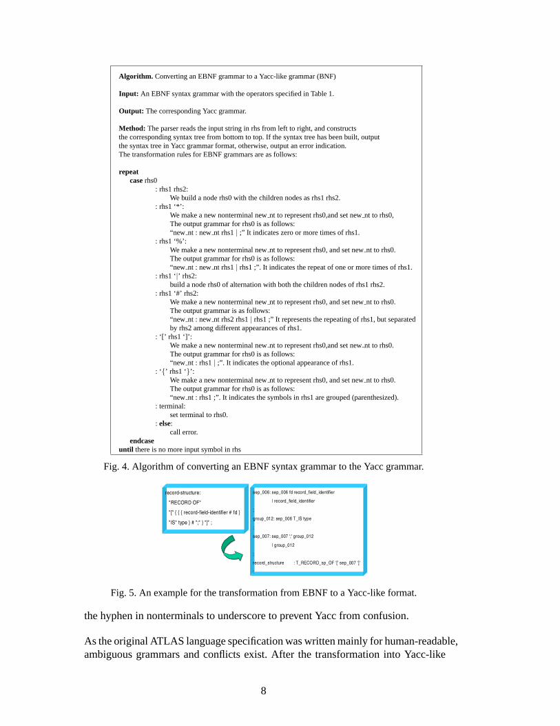
An example of the grammar in an EBNF form is listed below. It gives the declara-tion for record structures in ATLAS languages.
record-structure:"RECORD OF""[" { { { record-field-identifier # fd }"IS" type } # ";" } "]" ;
The example grammar in an EBNF format shown earlier for record declarationsare now translated into the form in Figure 5 according to our transformation algo-rithm. In the example, the algorithm described above recognizes the original EBNF“ record-field-identifier # fd ” as a sequence ofrecord-field-identifier sseparated byfd s when there are two or morerecord-field-identifier s, and ittransforms the grammar into “sep 006: sep 006 fd record field identifier| record field identifier; ”. Then it finds that “{sep 006 "IS" type }” isgrouped by braces, so it creates a new nonterminal and outputs the new grammar“group 012: sep 006 T IS type; ” to represent the group. There is another sep-aration statement, “group 012 # ";" ”, so it can be transformed into “sep 007:sep 007 ’;’ group 012 | group 012; ” as well. Finally, the top-level grammarcan be outputed: “record structure: T RECORDsp OF ’[’ sep 007 ’]’; ”. Wecan also notice that the meta-parser converts the keywords into tokens, and change
7
Algorithm. Converting an EBNF grammar to a Yacc-like grammar (BNF)
Input: An EBNF syntax grammar with the operators specified in Table 1.
Output: The corresponding Yacc grammar.
Method: The parser reads the input string in rhs from left to right, and constructsthe corresponding syntax tree from bottom to top. If the syntax tree has been built, outputthe syntax tree in Yacc grammar format, otherwise, output an error indication.The transformation rules for EBNF grammars are as follows:
repeatcaserhs0
: rhs1 rhs2:We build a node rhs0 with the children nodes as rhs1 rhs2.
: rhs1 ‘*’:We make a new nonterminal newnt to represent rhs0,and set newnt to rhs0,The output grammar for rhs0 is as follows:“new nt : newnt rhs1| ;” It indicates zero or more times of rhs1.
: rhs1 ‘%’:We make a new nonterminal newnt to represent rhs0, and set newnt to rhs0.The output grammar for rhs0 is as follows:“new nt : newnt rhs1| rhs1 ;”. It indicates the repeat of one or more times of rhs1.
: rhs1 ‘|’ rhs2:build a node rhs0 of alternation with both the children nodes of rhs1 rhs2.
: rhs1 ‘#’ rhs2:We make a new nonterminal newnt to represent rhs0, and set newnt to rhs0.The output grammar is as follows:“new nt : newnt rhs2 rhs1| rhs1 ;” It represents the repeating of rhs1, but separatedby rhs2 among different appearances of rhs1.
: ‘[’ rhs1 ‘]’:We make a new nonterminal newnt to represent rhs0,and set newnt to rhs0.The output grammar for rhs0 is as follows:“new nt : rhs1| ;”. It indicates the optional appearance of rhs1.
: ‘{’ rhs1 ‘}’:We make a new nonterminal newnt to represent rhs0, and set newnt to rhs0.The output grammar for rhs0 is as follows:“new nt : rhs1 ;”. It indicates the symbols in rhs1 are grouped (parenthesized).
: terminal:set terminal to rhs0.
: else:call error.
endcaseuntil there is no more input symbol in rhs
Fig. 4. Algorithm of converting an EBNF syntax grammar to the Yacc grammar.
record-structure:
"RECORD OF"
"[" { { { record-field-identifier # fd }
"IS" type } # ";" } "]" ;
sep_006: sep_006 fd record_field_identifier
| record_field_identifier
;
group_012: sep_006 T_IS type
;
sep_007: sep_007 ';' group_012
| group_012
;
record_structure : T_RECORD_sp_OF '[' sep_007 ']'
;
Fig. 5. An example for the transformation from EBNF to a Yacc-like format.
the hyphen in nonterminals to underscore to prevent Yacc from confusion.
As the original ATLAS language specification was written mainly for human-readable,ambiguous grammars and conflicts exist. After the transformation into Yacc-like
8
grammars, we further fine-tune the grammars to solve the grammar conflicts. Theusual conflict, for example, is from the leading commas in front of different lan-guage structures, and ambiguous grammars in generating null elements. Once thegrammar conflicts are solved, a parser is implemented to generate programs into anobject-oriented intermediate forms. We will describe the object-oriented represen-tations in the next sub-section.
3.2 The ATLAS abstract syntax tree
As the test programs were parsed by the parser, they should be translated to anintermediate form. Hence a completely class-library for the abstract syntax tree(AST) was designed for the intermediate form of parsed ATLAS programs. TheAST was built in the object-oriented technology; all the entities within the ASTwere represented by the C++ classes. The program information is constructed intree and table structures and described as follows.
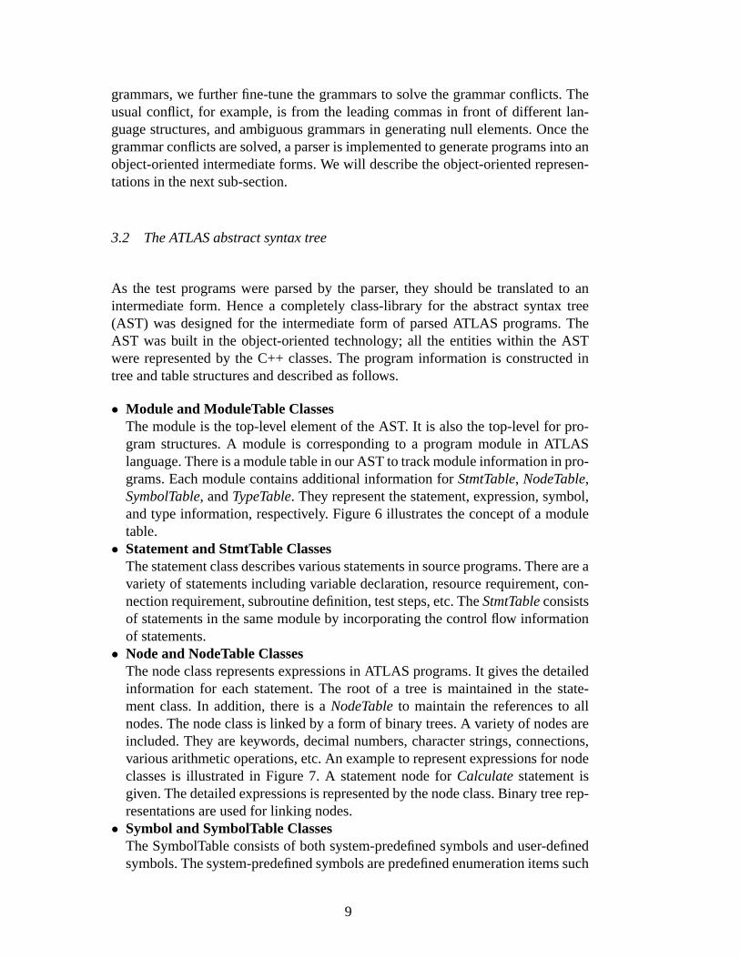
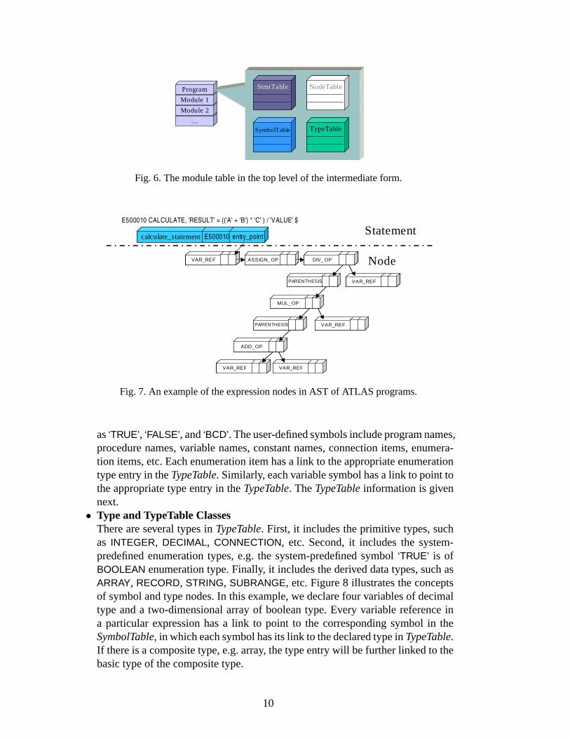
• Module and ModuleTable ClassesThe module is the top-level element of the AST. It is also the top-level for pro-gram structures. A module is corresponding to a program module in ATLASlanguage. There is a module table in our AST to track module information in pro-grams. Each module contains additional information forStmtTable, NodeTable,SymbolTable, andTypeTable. They represent the statement, expression, symbol,and type information, respectively. Figure 6 illustrates the concept of a moduletable.
• Statement and StmtTable ClassesThe statement class describes various statements in source programs. There are avariety of statements including variable declaration, resource requirement, con-nection requirement, subroutine definition, test steps, etc. TheStmtTableconsistsof statements in the same module by incorporating the control flow informationof statements.
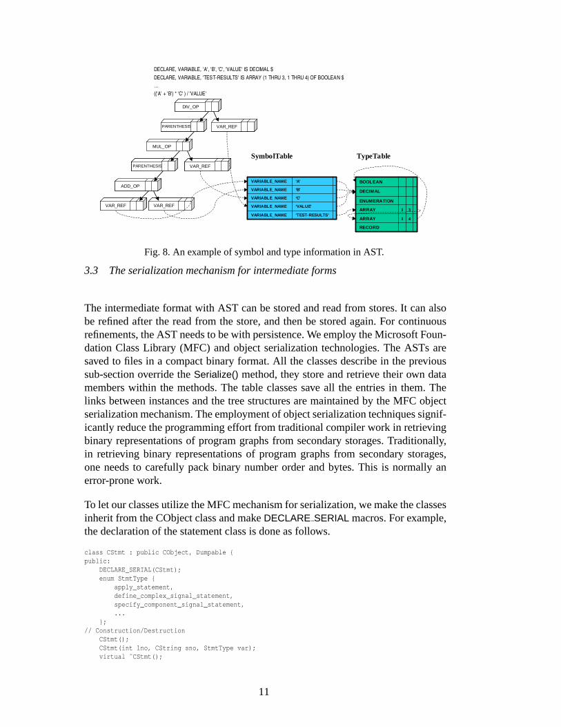
• Node and NodeTable ClassesThe node class represents expressions in ATLAS programs. It gives the detailedinformation for each statement. The root of a tree is maintained in the state-ment class. In addition, there is aNodeTableto maintain the references to allnodes. The node class is linked by a form of binary trees. A variety of nodes areincluded. They are keywords, decimal numbers, character strings, connections,various arithmetic operations, etc. An example to represent expressions for nodeclasses is illustrated in Figure 7. A statement node forCalculatestatement isgiven. The detailed expressions is represented by the node class. Binary tree rep-resentations are used for linking nodes.
• Symbol and SymbolTable ClassesThe SymbolTable consists of both system-predefined symbols and user-definedsymbols. The system-predefined symbols are predefined enumeration items such
9
…
Module 2
Module 1
Program StmtTableStmtTable NodeTabl eNodeTabl e
SymbolTableSymbolTable TypeTableTypeTable
Fig. 6. The module table in the top level of the intermediate form.
E500010 CALCULATE, 'RESULT' = (('A' + 'B') * 'C' ) / 'VALUE' $
calculate_statement E500010 entry_pointcalculate_statement E500010 entry_point
VAR_REF
PARENTHESIS
ASSIGN_OP DIV_OP
VAR_REF
MUL_OP
PARENTHESIS
ADD_OP
VAR_REF
VAR_REF
VAR_REF
VAR_REFVAR_REF
PARENTHESISPARENTHESIS
ASSIGN_OPASSIGN_OP DIV_OPDIV_OP
VAR_REFVAR_REF
MUL_OPMUL_OP
PARENTHESISPARENTHESIS
ADD_OPADD_OP
VAR_REFVAR_REF
VAR_REFVAR_REF
VAR_REFVAR_REF
Statement
Node
Fig. 7. An example of the expression nodes in AST of ATLAS programs.
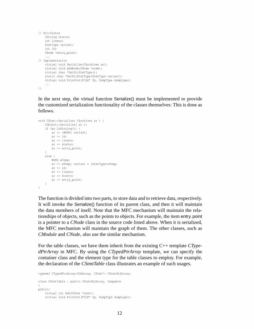
as‘TRUE’, ‘FALSE’, and‘BCD’. The user-defined symbols include program names,procedure names, variable names, constant names, connection items, enumera-tion items, etc. Each enumeration item has a link to the appropriate enumerationtype entry in theTypeTable. Similarly, each variable symbol has a link to point tothe appropriate type entry in theTypeTable. TheTypeTableinformation is givennext.
• Type and TypeTable ClassesThere are several types inTypeTable. First, it includes the primitive types, suchas INTEGER, DECIMAL, CONNECTION, etc. Second, it includes the system-predefined enumeration types, e.g. the system-predefined symbol‘TRUE’ is ofBOOLEAN enumeration type. Finally, it includes the derived data types, such asARRAY, RECORD, STRING, SUBRANGE, etc. Figure 8 illustrates the conceptsof symbol and type nodes. In this example, we declare four variables of decimaltype and a two-dimensional array of boolean type. Every variable reference ina particular expression has a link to point to the corresponding symbol in theSymbolTable, in which each symbol has its link to the declared type inTypeTable.If there is a composite type, e.g. array, the type entry will be further linked to thebasic type of the composite type.
10
DECLARE, VARIABLE, 'A', 'B', 'C', 'VALUE' IS DECIMAL $DECLARE, VARIABLE, 'TEST-RESULTS' IS ARRAY (1 THRU 3, 1 THRU 4) OF BOOLEAN $…(('A' + 'B') * 'C' ) / 'VALUE'
PARENTHESIS
DIV_OP
VAR_REF
MUL_OP
PARENTHESIS
ADD_OP
VAR_REF
VAR_REF
VAR_REFPARENTHESISPARENTHESIS
DIV_OPDIV_OP
VAR_REFVAR_REF
MUL_OPMUL_OP
PARENTHESISPARENTHESIS
ADD_OPADD_OP
VAR_REFVAR_REF
VAR_REFVAR_REF
VAR_REFVAR_REF
‘TEST-RESULTS’VARIABLE_NAME
‘VALUE'VARIABLE_NAME
‘C'VARIABLE_NAME
‘B'VARIABLE_NAME
‘A'VARIABLE_NAME
‘TEST-RESULTS’VARIABLE_NAME
‘VALUE'VARIABLE_NAME
‘C'VARIABLE_NAME
‘B'VARIABLE_NAME
‘A'VARIABLE_NAME
4
3
1ARRAY
BOOLEAN
RECORD
1ARRAY
ENUMERATION
DECIMAL
4
3
1ARRAY
BOOLEAN
RECORD
1ARRAY
ENUMERATION
DECIMAL
TypeTableSymbolTable
Fig. 8. An example of symbol and type information in AST.
3.3 The serialization mechanism for intermediate forms
The intermediate format with AST can be stored and read from stores. It can alsobe refined after the read from the store, and then be stored again. For continuousrefinements, the AST needs to be with persistence. We employ the Microsoft Foun-dation Class Library (MFC) and object serialization technologies. The ASTs aresaved to files in a compact binary format. All the classes describe in the previoussub-section override theSerialize() method, they store and retrieve their own datamembers within the methods. The table classes save all the entries in them. Thelinks between instances and the tree structures are maintained by the MFC objectserialization mechanism. The employment of object serialization techniques signif-icantly reduce the programming effort from traditional compiler work in retrievingbinary representations of program graphs from secondary storages. Traditionally,in retrieving binary representations of program graphs from secondary storages,one needs to carefully pack binary number order and bytes. This is normally anerror-prone work.
To let our classes utilize the MFC mechanism for serialization, we make the classesinherit from the CObject class and makeDECLARE SERIAL macros. For example,the declaration of the statement class is done as follows.
class CStmt : public CObject, Dumpable {public:
DECLARE_SERIAL(CStmt);enum StmtType {
apply_statement,define_complex_signal_statement,specify_component_signal_statement,...
};// Construction/Destruction
CStmt();CStmt(int lno, CString sno, StmtType var);virtual ˜CStmt();
11
// AttributesCString statno;int lineno;StmtType variant;int id;CNode *entry_point;...
// Implementationvirtual void Serialize(CArchive& ar);virtual void AddNode(CNode *node);virtual char *GetStrStmtType();static char *GetStrStmtType(StmtType variant);virtual void PrintOut(FILE* fp, DumpType dumptype);...
};
In the next step, the virtual functionSerialize() must be implemented to providethe customized serialization functionality of the classes themselves: This is done asfollows.
void CStmt::Serialize( CArchive& ar ) {CObject::Serialize( ar );if (ar.IsStoring()) {
ar << (WORD) variant;ar << id;ar << lineno;ar << statno;ar << entry_point;
}else {
WORD wTemp;ar >> wTemp; variant = (StmtType)wTemp;ar >> id;ar >> lineno;ar >> statno;ar >> entry_point;
}}
The function is divided into two parts, to store data and to retrieve data, respectively.It will invoke the Serialize() function of its parent class, and then it will maintainthe data members of itself. Note that the MFC mechanism will maintain the rela-tionships of objects, such as the points to objects. For example, the itementry pointis a pointer to aCNodeclass in the source code listed above. When it is serialized,the MFC mechanism will maintain the graph of them. The other classes, such asCModuleandCNode, also use the similar mechanism.
For the table classes, we have them inherit from the existing C++ templateCType-dPtrArray in MFC. By using theCTypedPtrArraytemplate, we can specify thecontainer class and the element type for the table classes to employ. For example,the declaration of theCStmtTableclass illustrates an example of such usages.
typedef CTypedPtrArray<CObArray, CStmt*> CStmtObjArray;
class CStmtTable : public CStmtObjArray, Dumpable{public:
virtual int Add(CStmt *stmt);virtual void PrintOut(FILE* fp, DumpType dumptype);
12
ATLAS Program
ATLAS Parser
XML Code
DTD or Schema
XSLStylesheet
Validation Test
Browser
BrowsableRepresentation
DOM Processor
Back-end
Testing Executable
Parsing tree (Program graph)
Dumping
Program traversing & manipulation
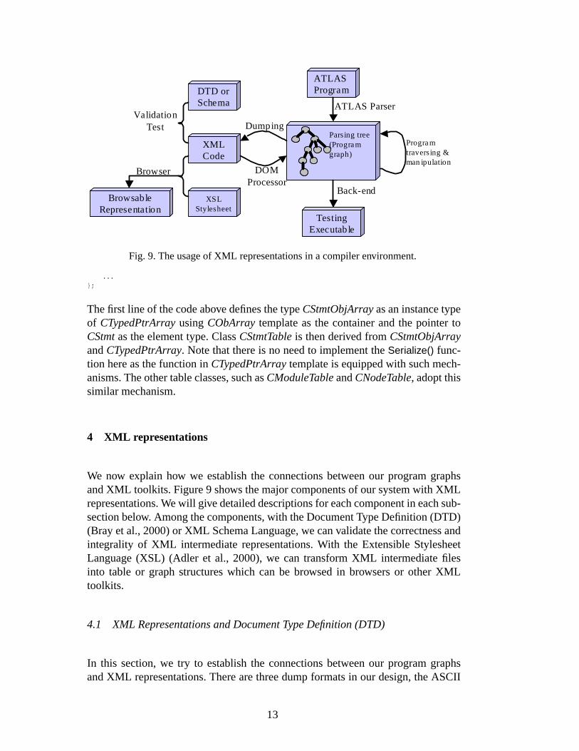
Fig. 9. The usage of XML representations in a compiler environment.
...};
The first line of the code above defines the typeCStmtObjArrayas an instance typeof CTypedPtrArrayusingCObArray template as the container and the pointer toCStmtas the element type. ClassCStmtTableis then derived fromCStmtObjArrayandCTypedPtrArray. Note that there is no need to implement theSerialize() func-tion here as the function inCTypedPtrArraytemplate is equipped with such mech-anisms. The other table classes, such asCModuleTableandCNodeTable, adopt thissimilar mechanism.
4 XML representations
We now explain how we establish the connections between our program graphsand XML toolkits. Figure 9 shows the major components of our system with XMLrepresentations. We will give detailed descriptions for each component in each sub-section below. Among the components, with the Document Type Definition (DTD)(Bray et al., 2000) or XML Schema Language, we can validate the correctness andintegrality of XML intermediate representations. With the Extensible StylesheetLanguage (XSL) (Adler et al., 2000), we can transform XML intermediate filesinto table or graph structures which can be browsed in browsers or other XMLtoolkits.
4.1 XML Representations and Document Type Definition (DTD)
In this section, we try to establish the connections between our program graphsand XML representations. There are three dump formats in our design, the ASCII
13
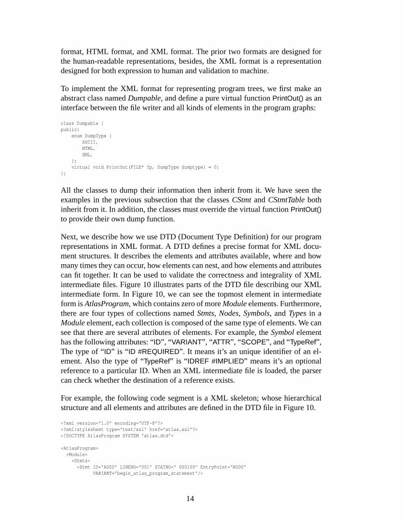
format, HTML format, and XML format. The prior two formats are designed forthe human-readable representations, besides, the XML format is a representationdesigned for both expression to human and validation to machine.
To implement the XML format for representing program trees, we first make anabstract class namedDumpable, and define a pure virtual functionPrintOut() as aninterface between the file writer and all kinds of elements in the program graphs:
class Dumpable {public:
enum DumpType {ASCII,HTML,XML,
};virtual void PrintOut(FILE* fp, DumpType dumptype) = 0;
};
All the classes to dump their information then inherit from it. We have seen theexamples in the previous subsection that the classesCStmtandCStmtTablebothinherit from it. In addition, the classes must override the virtual functionPrintOut()to provide their own dump function.
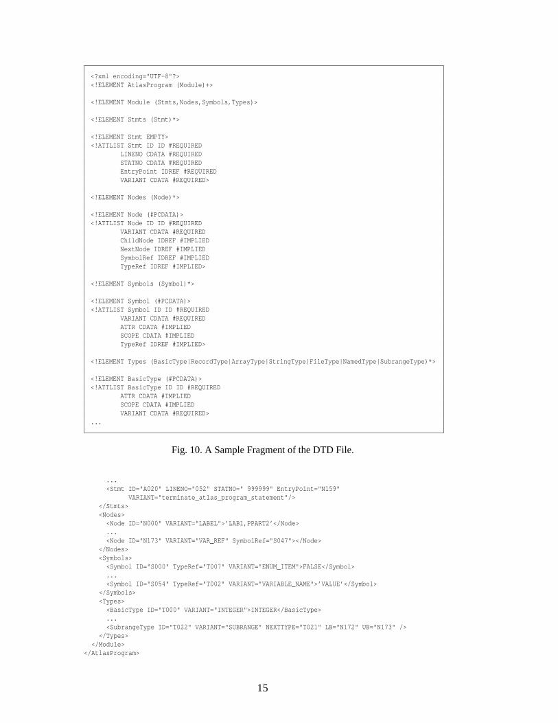
Next, we describe how we use DTD (Document Type Definition) for our programrepresentations in XML format. A DTD defines a precise format for XML docu-ment structures. It describes the elements and attributes available, where and howmany times they can occur, how elements can nest, and how elements and attributescan fit together. It can be used to validate the correctness and integrality of XMLintermediate files. Figure 10 illustrates parts of the DTD file describing our XMLintermediate form. In Figure 10, we can see the topmost element in intermediateform isAtlasProgram, which contains zero of moreModuleelements. Furthermore,there are four types of collections namedStmts, Nodes, Symbols, andTypesin aModuleelement, each collection is composed of the same type of elements. We cansee that there are several attributes of elements. For example, theSymbolelementhas the following attributes: “ID”, “ VARIANT”, “ ATTR”, “ SCOPE”, and “TypeRef”,The type of “ID” is “ ID #REQUIRED”. It means it’s an unique identifier of an el-ement. Also the type of “TypeRef” is “ IDREF #IMPLIED” means it’s an optionalreference to a particular ID. When an XML intermediate file is loaded, the parsercan check whether the destination of a reference exists.
For example, the following code segment is a XML skeleton; whose hierarchicalstructure and all elements and attributes are defined in the DTD file in Figure 10.
<?xml version="1.0" encoding="UTF-8"?><?xml:stylesheet type="text/xsl" href="atlas.xsl"?><!DOCTYPE AtlasProgram SYSTEM "atlas.dtd">
<AtlasProgram><Module>
<Stmts><Stmt ID="A000" LINENO="001" STATNO=" 000100" EntryPoint="N000"
VARIANT="begin_atlas_program_statement"/>
14
<?xml encoding="UTF-8"?><!ELEMENT AtlasProgram (Module)+>
<!ELEMENT Module (Stmts,Nodes,Symbols,Types)>
<!ELEMENT Stmts (Stmt)*>
<!ELEMENT Stmt EMPTY><!ATTLIST Stmt ID ID #REQUIRED
LINENO CDATA #REQUIREDSTATNO CDATA #REQUIREDEntryPoint IDREF #REQUIREDVARIANT CDATA #REQUIRED>
<!ELEMENT Nodes (Node)*>
<!ELEMENT Node (#PCDATA)><!ATTLIST Node ID ID #REQUIRED
VARIANT CDATA #REQUIREDChildNode IDREF #IMPLIEDNextNode IDREF #IMPLIEDSymbolRef IDREF #IMPLIEDTypeRef IDREF #IMPLIED>
<!ELEMENT Symbols (Symbol)*>
<!ELEMENT Symbol (#PCDATA)><!ATTLIST Symbol ID ID #REQUIRED
VARIANT CDATA #REQUIREDATTR CDATA #IMPLIEDSCOPE CDATA #IMPLIEDTypeRef IDREF #IMPLIED>
<!ELEMENT Types (BasicType|RecordType|ArrayType|StringType|FileType|NamedType|SubrangeType)*>
<!ELEMENT BasicType (#PCDATA)><!ATTLIST BasicType ID ID #REQUIRED
ATTR CDATA #IMPLIEDSCOPE CDATA #IMPLIEDVARIANT CDATA #REQUIRED>
...
Fig. 10. A Sample Fragment of the DTD File.
...<Stmt ID="A020" LINENO="052" STATNO=" 999999" EntryPoint="N159"
VARIANT="terminate_atlas_program_statement"/></Stmts><Nodes>
<Node ID="N000" VARIANT="LABEL">’LAB1,PPART2’</Node>...<Node ID="N173" VARIANT="VAR_REF" SymbolRef="S047"></Node>
</Nodes><Symbols>
<Symbol ID="S000" TypeRef="T007" VARIANT="ENUM_ITEM">FALSE</Symbol>...<Symbol ID="S054" TypeRef="T002" VARIANT="VARIABLE_NAME">’VALUE’</Symbol>
</Symbols><Types>
<BasicType ID="T000" VARIANT="INTEGER">INTEGER</BasicType>...<SubrangeType ID="T022" VARIANT="SUBRANGE" NEXTTYPE="T021" LB="N172" UB="N173" />
</Types></Module>
</AtlasProgram>
15
In the XML document above, the file begins with headers specifying the stylesheetfile and DTD file. The subsequent part defines the program graph in XML format.We can see that each element in a collection start with a tag name along with anattribute namedID, which is defined as a type “ID” in the DTD file. It means aunique identifier to the element. If there are references to a particular element, thesereferences will be embedded in an attribute of type “IDREF” in the DTD file. Forexample, the attributes “SymbolRef” in a “Node” tag and “TypeRef” in a “Symbol”are of type “IDREF”, and they express the references in AST.
4.2 The Extensible Stylesheet Language (XSL)
XSL, as a stylesheet language, supports separation of presentation and content, andit has considerable expressive power. By using XSL, we can transform XML doc-uments into other formats of documents. We have developed an XSL file to trans-form the XML representations to HTML representations to demonstrate the usage.Therefore, when Internet Explorer opens a XML intermediate file along with theassociated XSL file, the browser will annotate the XML file with HTML tags anddisplay it. The abundant tools for XML can be used for manipulations of programgraphs in XML representations.
In the usage of XSL to convert XML to HTML, The basic idea is converting avariety of elements in XML representation to particular tables respectively in aHTML file. Each row of a table contains an element along with its attributes. If theattribute is a IDREF, it fully utilizes the hyperlink to represent all connections be-tween nodes. Once the format in HTML format, users can easily traverse among thestatements and nodes and trace the links among symbols, types, and expressions.Furthermore, they can return to the original referencing states by just clicking theback button. This significantly reduces the effort to find cross-references amongnodes of program trees from traditional compiler infrastructures.
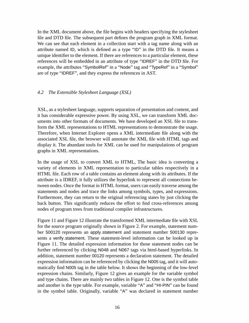
Figure 11 and Figure 12 illustrate the transformed XML intermediate file with XSLfor the source program originally shown in Figure 2. For example, statement num-ber 500120 represents anapply statement and statement number500130 repre-sents averify statement. These statement-level information can be looked up inFigure 11. The detailed expression information for those statement nodes can befurther referenced by clickingN048 andN067 tags via html-based hyperlinks. Inaddition, statement number00120 represents a declaration statement. The detailedexpression information can be referenced by clicking theN005 tag, and it will auto-matically findN005 tag in the table below. It shows the beginning of the low-levelexpression chains. Similarly, Figure 12 gives an example for the variable symboland type chains. There are mainly two tables in Figure 12. One is the symbol tableand another is the type table. For example, variable “A” and “HI-PIN” can be foundin the symbol table. Originally, variable “A” was declared in statement number
16
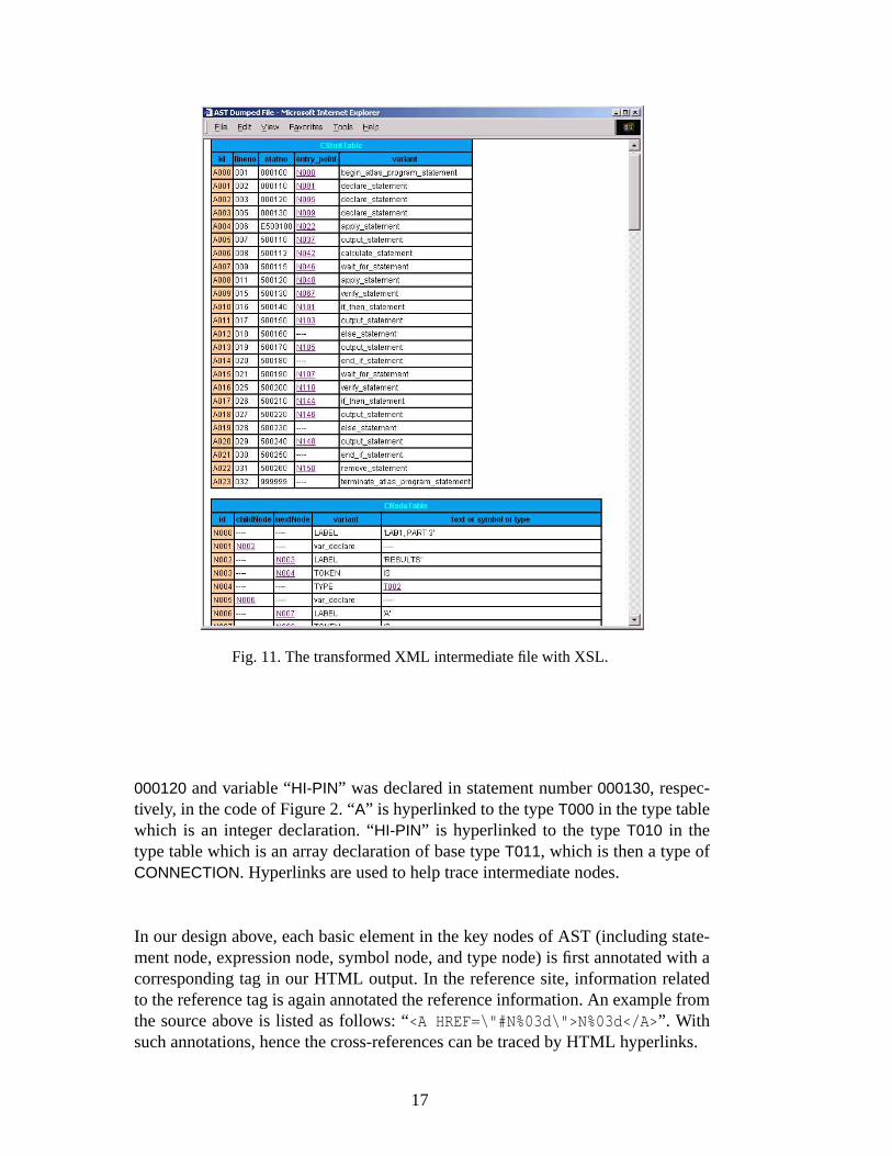
Fig. 11. The transformed XML intermediate file with XSL.
000120 and variable “HI-PIN” was declared in statement number000130, respec-tively, in the code of Figure 2. “A” is hyperlinked to the typeT000 in the type tablewhich is an integer declaration. “HI-PIN” is hyperlinked to the typeT010 in thetype table which is an array declaration of base typeT011, which is then a type ofCONNECTION. Hyperlinks are used to help trace intermediate nodes.
In our design above, each basic element in the key nodes of AST (including state-ment node, expression node, symbol node, and type node) is first annotated with acorresponding tag in our HTML output. In the reference site, information relatedto the reference tag is again annotated the reference information. An example fromthe source above is listed as follows: “<A HREF=\"#N%03d\">N%03d</A> ”. Withsuch annotations, hence the cross-references can be traced by HTML hyperlinks.
17
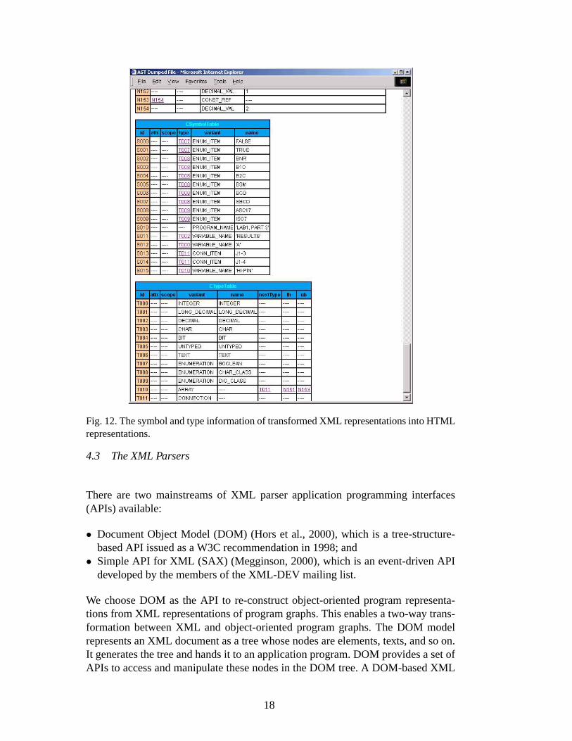
Fig. 12. The symbol and type information of transformed XML representations into HTMLrepresentations.
4.3 The XML Parsers
There are two mainstreams of XML parser application programming interfaces(APIs) available:
• Document Object Model (DOM) (Hors et al., 2000), which is a tree-structure-based API issued as a W3C recommendation in 1998; and
• Simple API for XML (SAX) (Megginson, 2000), which is an event-driven APIdeveloped by the members of the XML-DEV mailing list.
We choose DOM as the API to re-construct object-oriented program representa-tions from XML representations of program graphs. This enables a two-way trans-formation between XML and object-oriented program graphs. The DOM modelrepresents an XML document as a tree whose nodes are elements, texts, and so on.It generates the tree and hands it to an application program. DOM provides a set ofAPIs to access and manipulate these nodes in the DOM tree. A DOM-based XML
18
parser creates the entire structure of an XML document in memory.
A DOM document object is returned after we invoke the parser to process an XML-based intermediate file. By using the methodgetElementById() introduced in DOMLevel 2, we can select a particular element, whose ID is given by a string as aparameter, from a document entity. Therefore, the references to elements in theprogram graph can be traced in an XML-based intermediate file.
5 Experiments & Discussions
In this section, we performed experiments on compiling applications of ATLASsource programs to intermediate forms and stored them into files of XML andASCII formats, respectively. The ATLAS compiler was evaluated using a set ofATLAS source files to test data structures, expressions, control flows, functions,modules, and various test steps in ATLAS programs. As this is a joint project be-tween university and industrial research institute of Taiwan, the testing examplesp2.atl, p3.atl, p4.atl, p5.atl, p8.atl, p9.atl, p10.atl, and p11.atl are laboratory exam-ples from III (Institute for Information Industry) for testing and configurating sen-sor devices, stimulating UUT, and failure analysis. These samples are forwarded tous under the contract of Sekas Corp. and III, and the collaborations of III and ourinstitute. They are used as a preliminary test for a variety of constructs for ATLASprograms. Among the testing samples, p2.atl gives tests for the declaration con-structs of ATLAS programs. It includes the definition of digital configurations withsource and sensor device, the storage of arrays for stimulus words, the connectionvariables and boolean logics, etc. p3.atl gives the test on a variety of constructs re-lated to UUT. It includes the sense of UUT response, proving the UUT responseson UUT pins, stimulating UUT with the stimulus data, etc. Next, p4.atl gives es-sential test on the procedure routines in ATLAS programs. It includes the constructof routine declaration and the perform command. Next, p5.atl test programs on theconstruct of mixing control flows such as loops and procedure routines. p8.atl andp9.atl then give tests on command constructs of ATLAS programs such as require,apply, wait, measure, remove, etc. p10.atl and p11.atl give additional tests on com-mand constructs of ATLAS programs such as identify, enable, disable, monitor, etc.It also tests timer, events, frequency adjustments, voltage conditions, etc. In addi-tion, a large test case on industrial ATLAS source program (d37.atl) was used toevaluate our implementation. d37.atl was originally from NWA as a testing samplefor erratic failures and UUT components. The application is also forwarded from IIIwith their industrial partners. Note that d37.atl is more than 8500 LOC. It presentsa real industrial application program as our test case.
Table 2 summarizes the experiments. The experiments are done on a 450 MHzPentium II PC with 128 MB of RAM under Windows NT 4.0. The software is im-plemented by the Microsoft Visual C++ 6.0 compiler. Table 2 includes the compiler
19
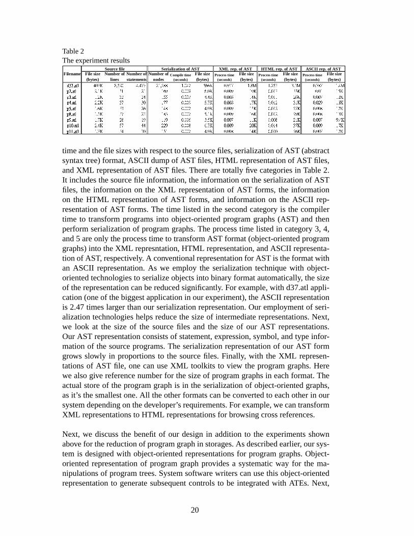
Table 2The experiment results
Filename File size(bytes)
Number oflines
Number ofstatements
Number ofnodes
Compile time(seconds)
File size(bytes)
Process time(seconds)
File size(bytes)
Process time(seconds)
File size(bytes)
Process time(seconds)
File size(bytes)������� � � ������� � � ������� � � ������� � � ����� � � ��� � �� ���� ��� � ����� � � � �� ������ ��� ��� � � � � � � � ����� ��� � � ��� ��� � � � ��
��� � � � ��� � � � ��� � � � ��� � � � ��� � ��� ��� � ��� ��� ����� ��� �� ��� ����� � �� ��� ��� � ���� ��� ��� � �� � ��� � � � ��� � � � ��� � � � ��� � � � � �� � � �� � ��� ��� ����� �� � ��� ����� � � ��� ����� ���� ��� ����� � �� ��� � � � ��� � � � ��� � � � ��� � � � ��� �� � � ��� � ��� ��� ����� ��� �� ��� ����� � �� ��� ��� � ��� ��� ����� � � ��� � � � ��� � � � ��� � � � ��� � � � � � �� � � ��� � �� ��� ����� �� �� ��� ����� � �� ��� ��� � ���� ��� ����� � �� ��� � � � ��� � � � ��� � � � ��� � � � � � �� � � ��� � ��� ��� ����� ��� � ��� ����� � �� ��� ��� � ���� ��� ����� � � �� � � � �� � � � �� � � � �� � � � � � �� � � � � ��� � ��� ����� ��� �� ��� ����� ��� ��� ����� ��� ��� ����� ��� � �"! # � � � �"! # � � � �"! # � � � �"! # � � � ��� � � � � ����� ��� ����� ��� �� ��� ����� ���� ��� ��� ���� ��� ����� � �� �"!�! � � � �"!�! � � � �"!�! � � � �"!�! � � � � � �� � ��� � ��� ��� ����� �� �� ��� ����� � � ��� ��� � ���� ��� ����� � ��
ASCII rep. of ASTXML rep. of ASTSource file Serialization of AST HTML rep. of AST
time and the file sizes with respect to the source files, serialization of AST (abstractsyntax tree) format, ASCII dump of AST files, HTML representation of AST files,and XML representation of AST files. There are totally five categories in Table 2.It includes the source file information, the information on the serialization of ASTfiles, the information on the XML representation of AST forms, the informationon the HTML representation of AST forms, and information on the ASCII rep-resentation of AST forms. The time listed in the second category is the compilertime to transform programs into object-oriented program graphs (AST) and thenperform serialization of program graphs. The process time listed in category 3, 4,and 5 are only the process time to transform AST format (object-oriented programgraphs) into the XML represntation, HTML representation, and ASCII representa-tion of AST, respectively. A conventional representation for AST is the format withan ASCII representation. As we employ the serialization technique with object-oriented technologies to serialize objects into binary format automatically, the sizeof the representation can be reduced significantly. For example, with d37.atl appli-cation (one of the biggest application in our experiment), the ASCII representationis 2.47 times larger than our serialization representation. Our employment of seri-alization technologies helps reduce the size of intermediate representations. Next,we look at the size of the source files and the size of our AST representations.Our AST representation consists of statement, expression, symbol, and type infor-mation of the source programs. The serialization representation of our AST formgrows slowly in proportions to the source files. Finally, with the XML represen-tations of AST file, one can use XML toolkits to view the program graphs. Herewe also give reference number for the size of program graphs in each format. Theactual store of the program graph is in the serialization of object-oriented graphs,as it’s the smallest one. All the other formats can be converted to each other in oursystem depending on the developer’s requirements. For example, we can transformXML representations to HTML representations for browsing cross references.
Next, we discuss the benefit of our design in addition to the experiments shownabove for the reduction of program graph in storages. As described earlier, our sys-tem is designed with object-oriented representations for program graphs. Object-oriented representation of program graph provides a systematic way for the ma-nipulations of program trees. System software writers can use this object-orientedrepresentation to generate subsequent controls to be integrated with ATEs. Next,
20
we establish the connection between the object-oriented program graph and XMLrepresentations. With the support of DTD and XSL files of XML environments, wecan perform machine validation on XML-based representations, transform XMLrepresentations into graph structures, and annotate the representations for humanbrowsing. This connection provides great flexibilities for ATLAS program trees tobe operated under XML tools. As described earlier, due to large number of key-words and command constructs in ATLAS languages, we need good software de-sign to make it easy to traverse program graphs and for consequent software de-velopments with ATE environments. Our design with XML representations makeit easy for developers dealing with program graphs to be able to view and connectprogram graphs and ATLAS command constructs with XML viewing tools. Ourwork presents the first-hand software experiences for the state of the art design andimplementation of a complex application domain language with object-orienteddesigns and XML representations.
The ATLAS program environment is now shiped to III (Institute for InformationIndustry, a local industrial research institute), aerospace division, under universityand industrial joint project contracts. Regarding to the constraints of our sysem,as we support IEEE standard compliant ATLAS-716-1995 parser, our system doesnot cover vendor extensions for ATLAS languages beyond IEEE standard com-pliant ATLAS-716-1995. The efforts for research and development in our site forthe compiler environments include two researchers for working one year. The com-piler infrastructure was then used by research engineers at III to generate controls towork with ATEs. The integrated platform was then used for test applications wherelong-term maintainability and reliability of UUTs (unit under test) was required.Our system system gives the essential components for ATLAS programming envi-ronments.
6 Conclusions
ATLAS has proven to be of substantial values in the automatic test specifications onATEs. We think our implementation of IEEE standard compliant ATLAS-716-1995parser can bring valuable experimental experiences for the ATE vendors. On top ofcurrent architecture and implementation, support for ATLAS-2000 (IEEE SCC-20,1997) could be easily done. Our compiler is also done with the employment ofadvanced software techniques including object-oriented representations, serializa-tions of objects, and the XML representation for AST information for employingabundant XML toolkits with compiler environments. Our software infrastructurecan be used for subsequent controls and specifications for ATEs. We think our workgives the first-hand software experiences for modern compiler systems on complexapplication domain-specific languages.
21
Acknowledgements
The authors express their gratitude to the anonymous reviewers for their valuablesuggestions and comments.
References
Adler, S., Berglund, A., Caruso, J., 2000. Extensible Stylesheet Language (XSL)Version 1.0, W3C Candidate Recommendation CR-xsl-20001121. (available athttp://www.w3.org/TR/xsl).
Aho, A.V., Sethi, R., Ullman, J.D., 1988. Compilers-Principles, Techniques andTools, Addison-Wesley.
Bray, T., Paoli, J., Maler, E., 2000. Extensible Markup Language (XML) 1.0(Second Edition), W3C Recommendation REC-xml-20001006. (available athttp://www.w3.org/TR/2000/REC-xml-20001006).
Chang, R.G., Chen, C.W., Chuang, T.R., Lee, J.K., 1997. Toward Automatic Sup-port of Parallel Sparse Computation in Java with Continuous Compilations, Con-currency: Practice and Experiences, Vol. 9(11), 1101-1111.
Chang, R.G., Li, J.S., Chuang, T.R., Lee, J.K., 2001. Probabilistic inferenceschemes for sparsity structures of Fortran 90 array intrinsics, International Con-ference on Parallel Processing, Spain.
Cortner, J.M., 1987. Digital Test Engineering, John Wiley & Sons, Inc.Donnoly, C., Stallman, R., 1995. Bison, the YACC-compatible Parser Generator,
Free Software Foundation, Cambridge, Massachusetts.Gannon, D., Lee, J.K., 1992. SIGMA II: A Tool Kit for Building Parallelizing Com-
pilers and Performance Analysis Systems, Proceedings of Programming Envi-ronments for Parallel Computing Conference, Edinburgh.
Holub, C., 1993. Compiler Design in C, Prentice-Hall Inc.Hors, A.L., H́egaret, P.L., Wood, L., 2000. Document Object Model (DOM) Level
2 Core Specification Version 1.0, W3C Recommendation REC-DOM-Level-2-Core-20001113. (available at http://www.w3.org/TR/DOM-Level-2-Core).
Hulme, A.M.B., 1996. The ATLAS language-panacea or pariah? Does it only spec-ify the task or does it really drive the tester?, IEEE Aerospace and ElectronicsSystems Magazine, 11(3):29–34.
Hutt, A.T., 1994. Object Analysis and Design, Object Management Group, JohnWiley & Sons, Inc.
Hwang, G.H., Lee, J.K., Ju, D.Z., 1998. A Function-Composition Approach to Syn-thesize Fortran 90 Array Operations, Journal of Parallel and Distributed Comput-ing, 54, 1-47.
Hwang, G.H., Lee, J.K., Ju, D.Z., 2001. Array operation synthesis to optimize HPFprograms on distributed memory machines, Journal of Parallel and DistributedComputing, 61, 467-500.
22
IEEE SCC-20, 1997. ATLAS-2000 Test Language Requirements Document, IEEESCC-20 Log No. 716-051.
IEEE Std 771-1998, 1998. IEEE guide to the use of the ATLAS specification, IEEE,Inc.
IEEE Std 716-1995, 1995. IEEE standard test language for all systems-Common/Abbreviated Test Language for All Systems (C/ATLAS), IEEE, Inc.
Lee, J.K., Tsaur, I.K., Hwang, S.Y., 1997. Parallel Array Object I/O Support onDistributed Environments, Journal of Parallel and Distributed Computing, 40,227-241.
Mason, T., Brown, D., 1990. lex & yacc, O’Reilly.Megginson, D., 2001. SAX 2.0: The Simple API for XML, XML-DEV mailing list.
(available at http://www.saxproject.org/).Parker, K.P., 1987. Integrating Design and Test: Using CAE Tools for ATE Pro-
gramming, Computer Society Press of the IEEE.Paxson, V., 1995. Flex, version 2.5, A fast scanner genera-
tor, The Regents of the University of California. (available athttp://www.math.utah.edu/docs/info/flextoc.html).
Wilson, R.P., French, R.S., Wilson, C.S., Amarasinghe, S.P., Anderson, J.M.,Tjiang, S.W.K., Liao, S.W., Tseng, C.W., Hall, M.W., Lam, M.S.M., Hennesy,J.L., 1994. SUIF: An Infrastructure for research on parallelizing and optimizingcompilers, ACM SIGPLAN Notices, 29(12): p. 31-37.
Wu, J.Z., Lee, J.K., 2000. A bytecode optimizer to engineer bytecodes for perfor-mances, in Languages and compilers for high-performance computing (LCPC’00), USA.
Cheng-Wei Chenreceived his B.S. degree in computer science and informationengineering from Yuan Ze University and M.S. degree in computer science fromNational Tsing-Hua University in 1995 and 1997, respectively. He is currently aPh.D. candidate, Department of Computer Science, National Tsing-Hua University,Taiwan. His research interests include object-oriented and parallel languages, thesoftware for component-based environments, and compiler designs.
Jenq Kuen Leereceived the B.S. degree in computer science from National TaiwanUniversity in 1984. He received a Ph.D. in computer science from Indiana Univer-sity in 1992, where he also received a M.S. (1991) in computer science. He was akey member of the team who developed the first version of the pC++ language andSIGMA system while at Indiana University. He joined the Department of ComputerScience at National Tsing-Hua University, Taiwan, in 1992. Since then, he estab-lished a programming language research lab. there to develop advanced compilertoolkits for embedded systems and modern microprocessors. He is now a profes-sor and vice-chairman with the computer science department, National Tsing-HuaUniv., Taiwan. He was a recipient of the most original paper award in ICPP ’97with the paper entitled “Data Distribution Analysis and Optimization for Pointer-Based Distributed Programs”. The dissertation of his Ph.D. student, Gwan-HwanHwang, also received the distinguished dissertation award as honorable mention by
23
IICM of Taiwan, 1999. He was also a receipient for a Taiwan MOE award, 2001,on delivering compiler technologies for advancing the related industry sector inTaiwan.
He currently participated in the NSC/MOE research excellence project of Taiwanin developing advanced system software for pervasive computings, in the USA-NSF/Taiwan-NSC joint project as an international effort to develop advanced com-piler toolkits for SoC designs, and in MOEA Project of Taiwan on Compiler Tech-nologies for SoC designs. His current research interests include optimizing compil-ers, SDK toolkits and ISA specifications for SoC designs, Java software for perva-sive computings, and parallel object-oriented languages and systems.
24