an inside view of thermal power stations and ddcmis in power plants
TRANSCRIPT
AN INSIDE VIEW OF THERMAL POWER STATION AND DCS USED IN
POWER PLANTSBy R.G.LOKKESH
(my sincere thanks to my father and his colleagues for making this
successful)
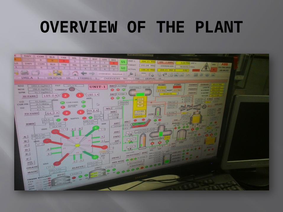
OVERVIEW OF THE PLANT

BOILER GENERAL LAYOUT

Firstly the pulverised coal(lignite) particles was sent to the boiler from bunkers. the difference between coal and the lignite is lignite contains more amount of water and coal contains more amount of ash. In thermal plants we are using lignite so to remove the moisture content hot air is passed towards it(red line in the dig) then as the water content is removed which is the used to cluster the particles ,thus the particles become again pulverised or break down to smaller particles further. then it is again passed through mill and then to the boiler furnace. The boiler oil is used for lighting up furnace initially. There are 3 types of oil used in power plants..
Volume of one unit mass of steam is thousand times that of water. when water is converted to steam in a closed vessel the pressure will increase. Boiler uses this principle. 1unit mass of steam=1000 m3 of waterThe boiler is maintained in 1000deg.the blue colour line indicate hot air from air preheater to supplied for burning the coal and the red line indicates hot air for pulverising the coal and removing moisture it will also take heat from the flue gas but no aux equipments is needed as you can see the interaction of two pipes in fig..a low pressure is maintained inside the boiler so that the outer air will get sucked inside and hot air from the boiler will not go outside.SH represents super heated steam and RH represents reheated steam. then the steam is collected in the drum and sent to the turbine(not shown)and then the flue gas is sent through RAPH and then to electro static precipitator to removes the fine particles like smoke and dust and then through the chimney. This chimney will be made of 220-320m height .As height increase the radius of unwanted particles falling on to ground increases, so it is safe if we increase the height. inside boilers water wall tubes were used which will be like as shown in fig
RAPH is an rotating plate regenerative air preheater which is used to collect heat from the flue gas and then uses this heat to heat the atmospheric air and sends it inside the boiler. This air preheater will be round in shape and has a bisects in it in which at one side of blade will absorb heat and as it was rotating when it comes to other side the atmospheric air flows over it and thus it absorbs heat(shown in fig).SCAPH is steam coil air preheater used for same purpose.

BOILER AIR
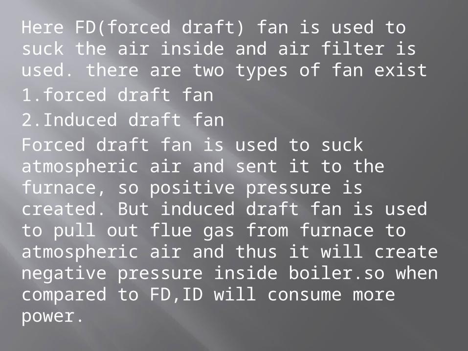
Here FD(forced draft) fan is used to suck the air inside and air filter is used. there are two types of fan exist 1.forced draft fan 2.Induced draft fanForced draft fan is used to suck atmospheric air and sent it to the furnace, so positive pressure is created. But induced draft fan is used to pull out flue gas from furnace to atmospheric air and thus it will create negative pressure inside boiler.so when compared to FD,ID will consume more power.
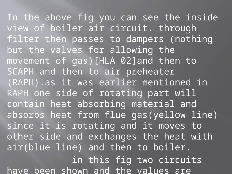
In the above fig you can see the inside view of boiler air circuit. through filter then passes to dampers (nothing but the valves for allowing the movement of gas)[HLA 02]and then to SCAPH and then to air preheater (RAPH).as it was earlier mentioned in RAPH one side of rotating part will contain heat absorbing material and absorbs heat from flue gas(yellow line) since it is rotating and it moves to other side and exchanges the heat with air(blue line) and then to boiler. in this fig two circuits have been shown and the values are mentioned in it .
BOILER FLUE GAS
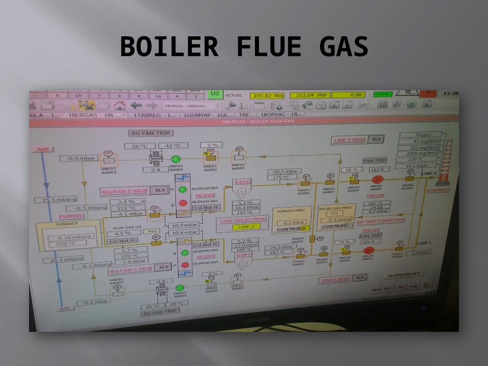
This fig is nothing but the extension of the before fig the flue gas circuit extension, which will contain again an ID fan which sucks the flue gas from the furnace and send it to chimney. again you can see a yellow line going inside furnace through RG fan which is flue gas is again sent for reheating.
THERMAL CYCLE LAYOUT
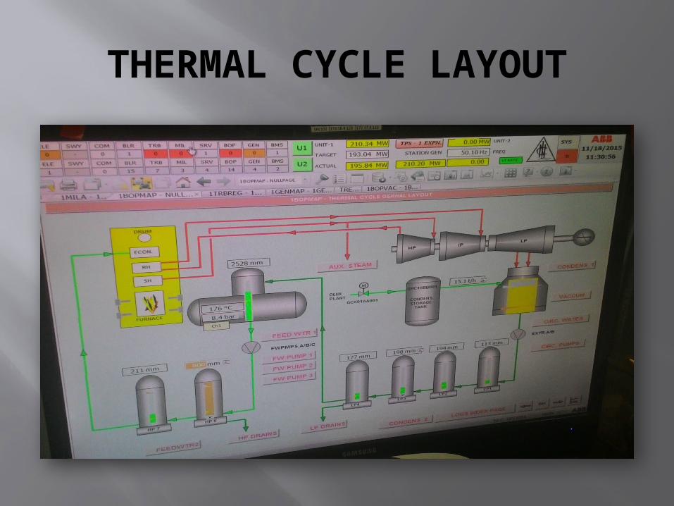
The super heated steam is first passed to the high pressure turbine and then it is passed to reheater and then only it is passed to intermediate and low pressure turbine as they both are coupled each other, but the HP is not coupled to IP and LP.the air from HP is passed to reheater because the temperature will decrease below 350deg and pressure also decreases due to which the steam may contain moisture so to remove the moisture content the steam is again heated using reheater were the steam is heated using flue gas. then after passing through the turbines steam is condensed using cooling tower .

Remember the water coming out of condensor is the demineralised water and it is passed through the LP(low pressure) tank where the pressure of the water is gradually increased by passing it through 4 LP tank. Then from LP4 it passes to
Deaeration tank in which the oxygen and minerals are removed.Note: in the fig you can see that there is very slight increase in temp .the temp at chimney is170deg and temp at deaeration tank is 176deg ,so only the pressure gets changed and then the stea, is passed to HP tank where the pressure is further increased and then sent to boiler.
CONDENSATOR - LPHEATER CIRCUIT
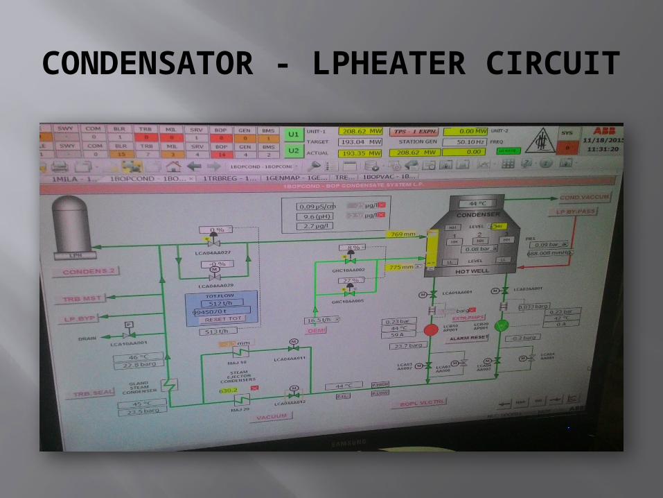
There wont be more explenation required for this fig as you can able to understand. There will inlet valves used and bypass inlet valves are used to reduce the pressure acting. for example see if we want to open the valve in the direction opposite to the more pressure acting ,it is difficult but what if we reduce the pressure so that there is only less pressure difference exists. The same principle is used here the bypass valves will be of smaller radius so the water is allowed to pass through it and the pressure gets decreased and once the pressure difference gets small the inlet valve having larger radius is opened.
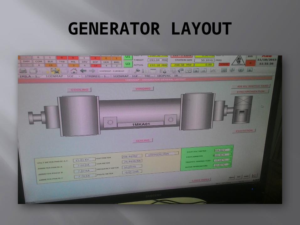
GENERATOR LAYOUT

In this in right side corner ,you can see a turbine connected to rotor part of generator. normally the rotor will have 2 poles and which can able to rotate at 3600 rpm for 2min and the speed of rpm changes as per number of poles. here the two poles are created by the electro magnets which are excited by using dc so that poles wont be changing.
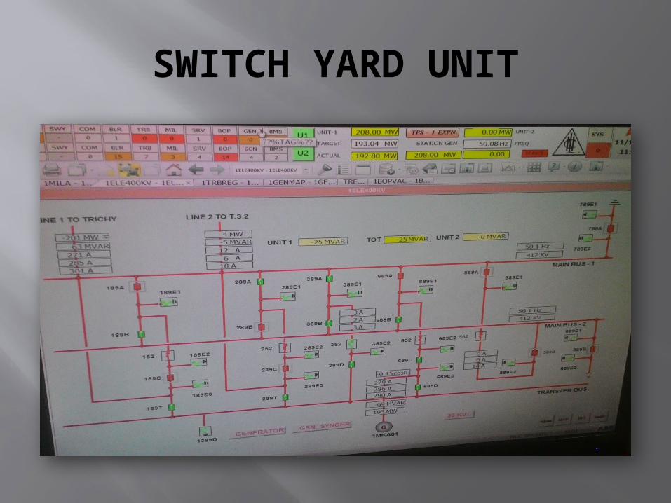
SWITCH YARD UNIT
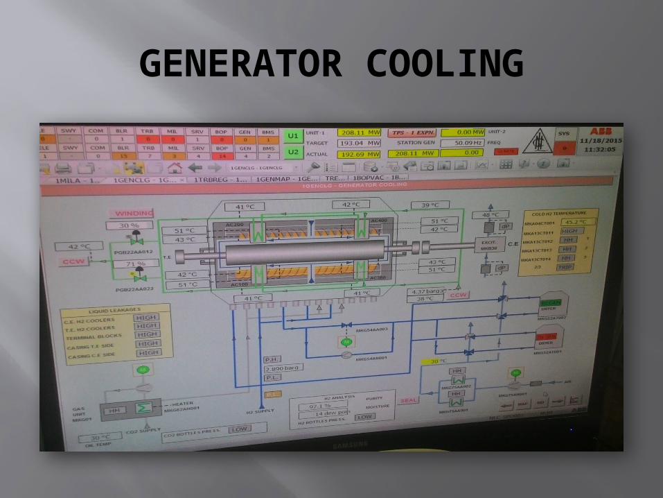
GENERATOR COOLING
an important thing to remember is there are totally two types f water is used in the total circuit.1.demineralised water – steam in boiler 2.Ordinary water – cooling purpose in cooling tower

INSIDE VIEW OF GENERATOR

Generator is ac motor. in this rotor will have magnetic poles on it and stator will have conducting conductors. Here armature will not be kept in rotor because it is difficult to pass the current through brushes in the rotor. as you can see in this fig that stator part is being under maintenance.. and you can see the conducting conductors are laminated.
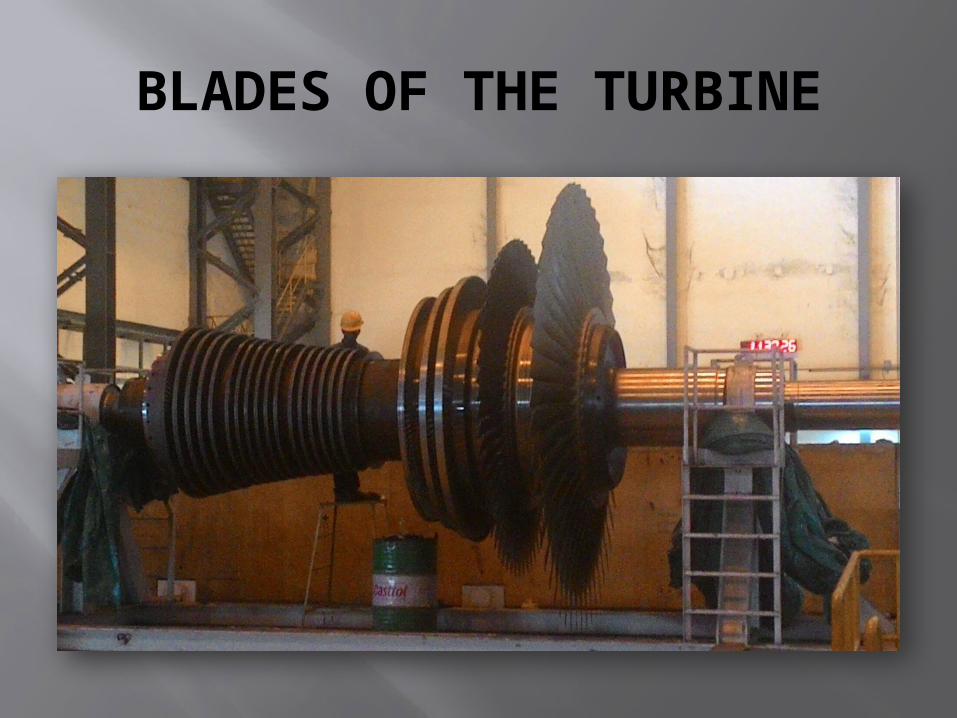
BLADES OF THE TURBINE
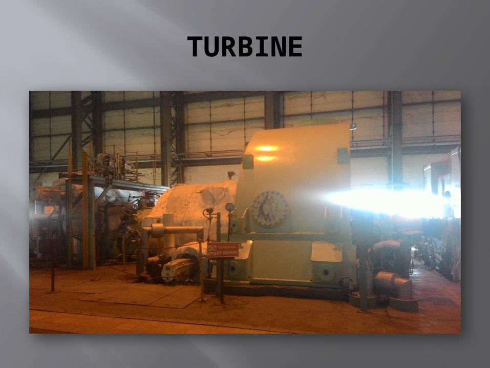
TURBINE

TURBINE COUPLED TO GENERATOR

Inside a generator hydrogen gas was filled to reduce the heat produced in the current carrying conductors. Since hydrogen is explosive in air it is sealed inside and protected by oil.
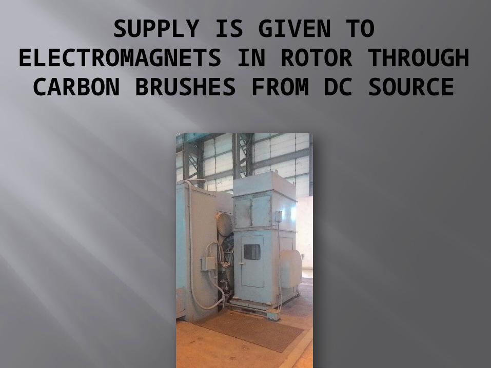
SUPPLY IS GIVEN TO ELECTROMAGNETS IN ROTOR THROUGH CARBON BRUSHES
FROM DC SOURCE
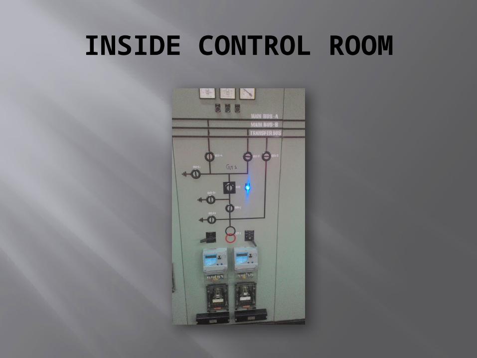
INSIDE CONTROL ROOM
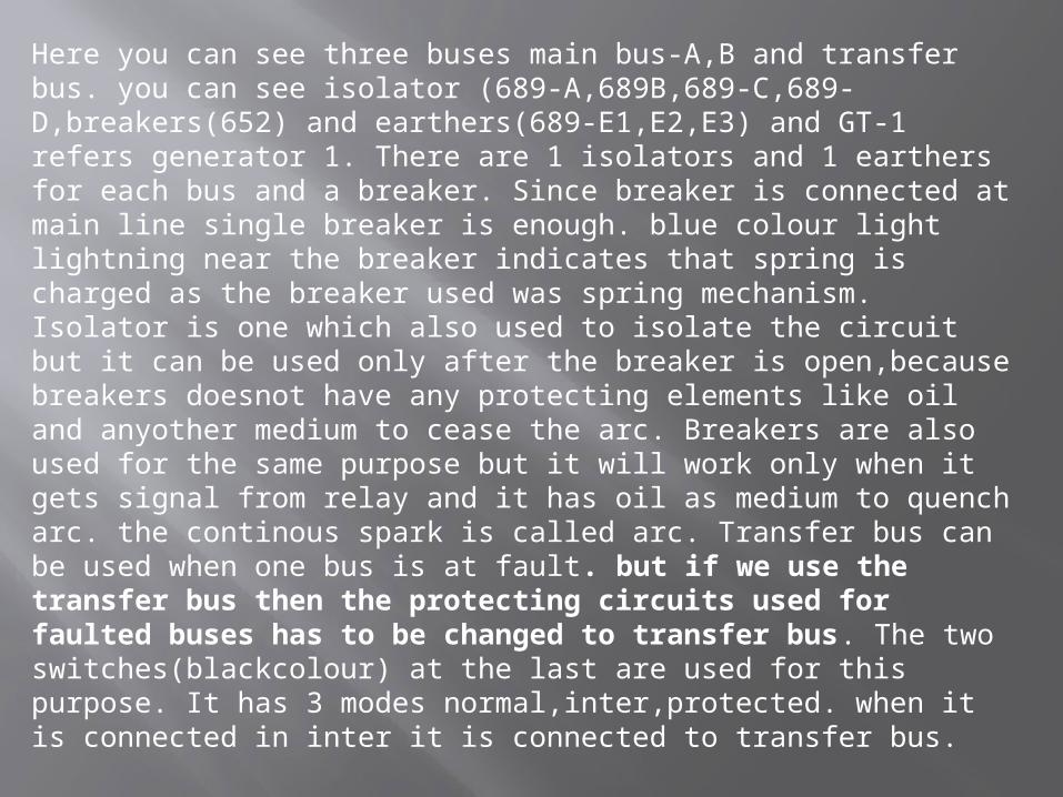
Here you can see three buses main bus-A,B and transfer bus. you can see isolator (689-A,689B,689-C,689-D,breakers(652) and earthers(689-E1,E2,E3) and GT-1 refers generator 1. There are 1 isolators and 1 earthers for each bus and a breaker. Since breaker is connected at main line single breaker is enough. blue colour light lightning near the breaker indicates that spring is charged as the breaker used was spring mechanism. Isolator is one which also used to isolate the circuit but it can be used only after the breaker is open,because breakers doesnot have any protecting elements like oil and anyother medium to cease the arc. Breakers are also used for the same purpose but it will work only when it gets signal from relay and it has oil as medium to quench arc. the continous spark is called arc. Transfer bus can be used when one bus is at fault. but if we use the transfer bus then the protecting circuits used for faulted buses has to be changed to transfer bus. The two switches(blackcolour) at the last are used for this purpose. It has 3 modes normal,inter,protected. when it is connected in inter it is connected to transfer bus.
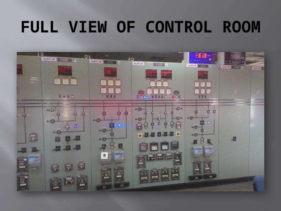
FULL VIEW OF CONTROL ROOM

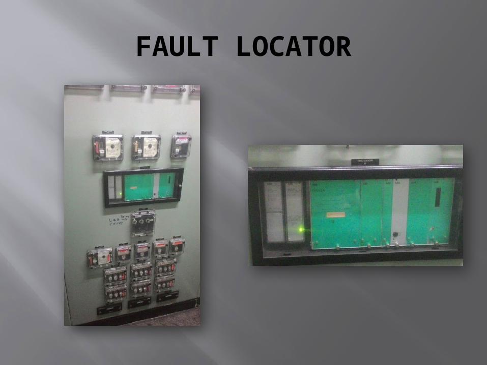
FAULT LOCATOR
Fault locator is an device used to find the point on the line at which fault had occurred.There are totally two methods are used to find it,1.Impedance method2.Travelling wave method

A VIEW OF SWITCH YARD CONTROLROOM

ANOTHER VIEW OF SWITCH YARD CONTROL ROOM

PANTOGRAPH TYPE ISOLATOR OPEN CONDITION CLOSED
CONDITION
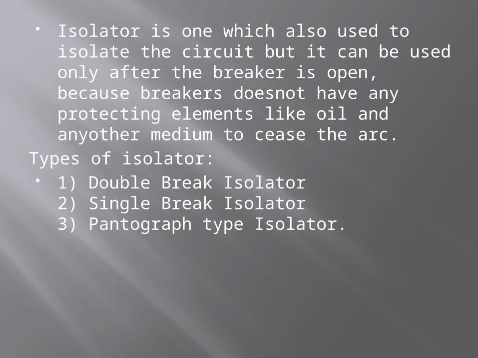
Isolator is one which also used to isolate the circuit but it can be used only after the breaker is open, because breakers doesnot have any protecting elements like oil and anyother medium to cease the arc.
Types of isolator: 1) Double Break Isolator
2) Single Break Isolator3) Pantograph type Isolator.

EARTHERS
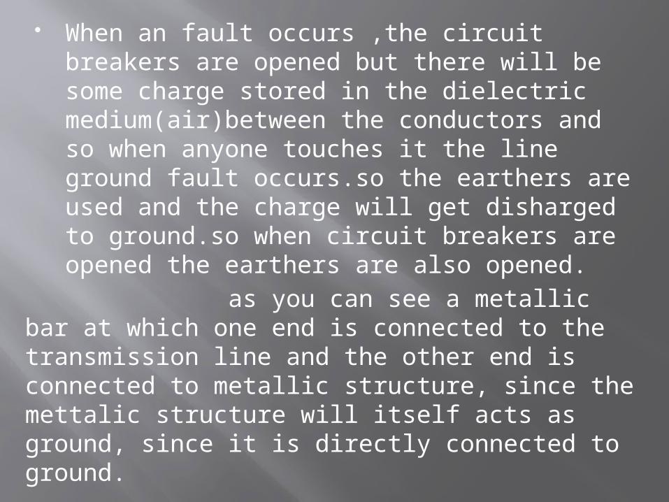
When an fault occurs ,the circuit breakers are opened but there will be some charge stored in the dielectric medium(air)between the conductors and so when anyone touches it the line ground fault occurs.so the earthers are used and the charge will get disharged to ground.so when circuit breakers are opened the earthers are also opened.
as you can see a metallic bar at which one end is connected to the transmission line and the other end is connected to metallic structure, since the mettalic structure will itself acts as ground, since it is directly connected to ground.
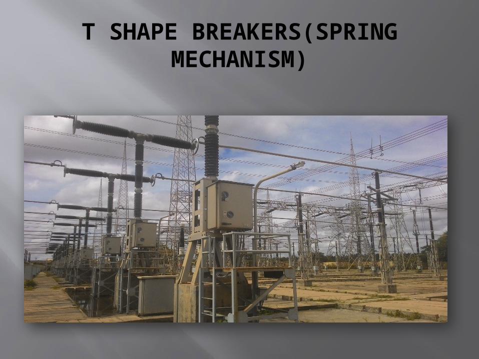
T SHAPE BREAKERS(SPRING MECHANISM)

Circuit Breaker: circuit breakers are used to isolate the faulty line when the relay circuit senses the fault. Types of circuit breaker:
According to their arc quenching (rapid cooling) media the circuit breaker can be divided as:
1) Air circuit breaker 2) Oil circuit breaker 3) Vacuum circuit breaker 4) SF6 circuit breaker According to their services the circuit breaker can be divided as: 1) Outdoor circuit breaker 2) Indoor circuit breaker According to the operating mechanism of circuit breaker they can be
divided as: 1) Spring operated circuit breaker 2) Pneumatic circuit breaker 3) Hydraulic circuit breaker According to the voltage level of installation types of circuit breaker are
referred as: 1) High voltage circuit breaker (> 72 kV) 2) Medium voltage circuit breaker (1-72 kV) 3) Low voltage circuit breaker (< 1 kV)

T shape breakers are shown in fig and they has an special advantage, since they are in T shape, the distance between the further most ends are more and the potential difference is also divided so the formation of arch gets reduced and SF6 is used in medium.
Here is the link: https://youtu.be/GSh0f94JwaA Watch this, it is an animated working principle of automated circuit breaker and no need of relays.in this they uses bimetallic strip which expands and contracts for opening and closing of circuit breaker.

COOLING TOWER Cooling tower Vertical pump
Cooling towers are in the shape of hyperbolic because it will cause natural air circulation. The middle part of the the cooling tower will have low pressure and the bottom and top most will have high pressure. remember these pressure is created by atmospheric air (i.e) the atmospheric air outside will be going inside the tower due to low pressure region created in the middle due to which high pressure region is created at bottom and top ends of the cooling tower. since atmospheric air flows from down to upside and the hot water is falling down from upside to down side,thus the hot water and air is flowing in counter direction so natural cooling takes place and these air will absorb the heat and flow to the atmosphere again through the top. Also it takes only very less amount of cement and concrete is needed. a vertical pump is used in the cooling tower raising up the water to that height.