an intelligent real time 3d vision system for robotic
TRANSCRIPT

An intelligent real time 3D vision system for robotic welding tasks
RODRIGUES, Marcos <http://orcid.org/0000-0002-6083-1303>, KORMANN, Mariza, SCHUHLER, C and TOMEK, P
Available from Sheffield Hallam University Research Archive (SHURA) at:
http://shura.shu.ac.uk/7279/
This document is the author deposited version. You are advised to consult the publisher's version if you wish to cite from it.
Published version
RODRIGUES, Marcos, KORMANN, Mariza, SCHUHLER, C and TOMEK, P (2013). An intelligent real time 3D vision system for robotic welding tasks. In: Mechatronics and its applications. IEEE Xplore, 1-6.
Copyright and re-use policy
See http://shura.shu.ac.uk/information.html
Sheffield Hallam University Research Archivehttp://shura.shu.ac.uk
MARWIN: An Intelligent Real Time 3D Vision Systemfor Robotic Welding Tasks*
Marcos Rodrigues1, Mariza Kormann1, Clement Schuhler2, Geoff Melton2, Jakub Shejbal3 and Peter Tomek3
Abstract— MARWIN is an intelligent system for automaticrobotic welding tasks. It extracts welding parameters andcalculates robot trajectories directly from CAD models whichare then verified by real-time 3D scanning and registration.The focus of this paper is on describing a novel mathematicalformulation for structured light scanning together with thedesign and testing of the 3D vision system and show howsuch technology can be exploited within an anthropomaticcontext. The expected end result is a 3D assisted user-centredrobot environment in which a task is specified by the userby simply confirming (and/or adjusting) MARWIN’s suggestedparameters and welding sequences.
I. INTRODUCTIONWelding by robots has experienced a vigorous upsurge in
recent years with an estimated 25% of all industrial robotsbeing used in connection to welding tasks [1]. The challengeis to develop flexible automation systems that can be setup quickly and can be switched over to another productline while maintaining quality and profitability. Small andmedium enterprises (SMEs) normally do not have the re-sources to invest in technology requiring extensive humantraining. The MARWIN project offers a solution to human-robot interaction by developing a cognitive welding robotwhere welding tasks and parameters are intuitively selectedby the end-user directly from a library of CAD models.Robot trajectories are then automatically calculated from theCAD models and validated through fast 3D scanning of thewelding scene. The role of the user is limited to high levelspecification of the welding task and to the confirmationand/or changing of welding parameters and sequences assuggested by MARWIN.
This paper focuses on describing the MARWIN 3D visionsystem and a novel mathematical formulation for fast 3Dscanning using structured light, and on methods to registerscanned surfaces to CAD models and estimation of registra-tion errors. The main idea behind the 3D vision system isthat, if the scanned model matches the description of theirCAD counterparts, then welding can proceed as calculated
*This work is supported by the European Commission, MARWIN ProjectGrant 286284 Research for SMEs – SME-2011-1, from Nov 2011 to Oct2013.
1Marcos Rodrigues and Mariza Kormann are with the Geometric Mod-elling and Pattern Recognition Group, Communication and ComputingResearch Centre, Sheffield Hallam University, UK, {m.rodrigues,m.kormann} at shu.ac.uk
2Clement Schuhler and Geoff Melton are with TWI Cambridge, UK,{clement.schuhler, geoff.melton} at twi.co.uk
3Jakub Shejbal and Peter Tomek are with MFKK, Budapest, Hungary,{jakub.shejbal, peter.tomek} at mfkk.hu
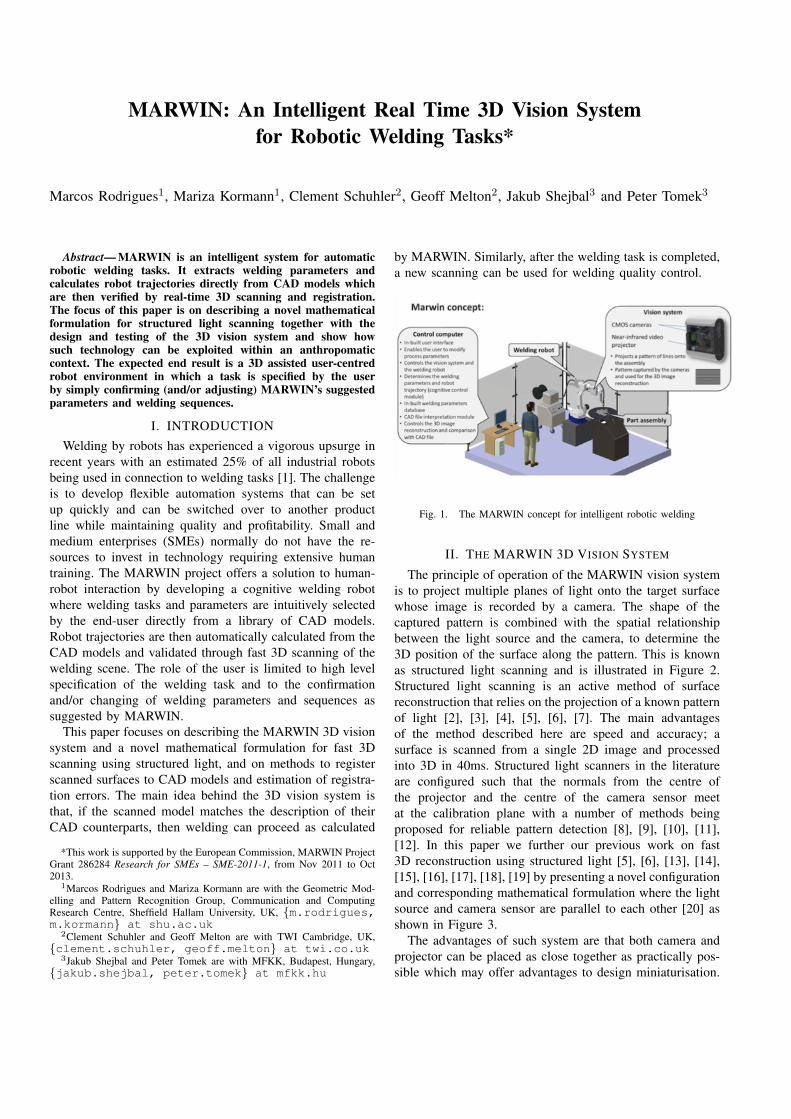
by MARWIN. Similarly, after the welding task is completed,a new scanning can be used for welding quality control.
Fig. 1. The MARWIN concept for intelligent robotic welding
II. THE MARWIN 3D VISION SYSTEM
The principle of operation of the MARWIN vision systemis to project multiple planes of light onto the target surfacewhose image is recorded by a camera. The shape of thecaptured pattern is combined with the spatial relationshipbetween the light source and the camera, to determine the3D position of the surface along the pattern. This is knownas structured light scanning and is illustrated in Figure 2.Structured light scanning is an active method of surfacereconstruction that relies on the projection of a known patternof light [2], [3], [4], [5], [6], [7]. The main advantagesof the method described here are speed and accuracy; asurface is scanned from a single 2D image and processedinto 3D in 40ms. Structured light scanners in the literatureare configured such that the normals from the centre ofthe projector and the centre of the camera sensor meetat the calibration plane with a number of methods beingproposed for reliable pattern detection [8], [9], [10], [11],[12]. In this paper we further our previous work on fast3D reconstruction using structured light [5], [6], [13], [14],[15], [16], [17], [18], [19] by presenting a novel configurationand corresponding mathematical formulation where the lightsource and camera sensor are parallel to each other [20] asshown in Figure 3.
The advantages of such system are that both camera andprojector can be placed as close together as practically pos-sible which may offer advantages to design miniaturisation.

Chapter 3 – Structured light scanning
3.1 THE LAYOUT OF OUR SCANNER
Figure 3.1 illustrates the basic concept of a structured light scanner which utilizes a pattern
of horizontal stripes. A projector is utilized to cast the pattern onto the surface of a target
object, and a camera captures an image of the scene. Information retrieved from the image
is combined with the geometric relationship between the projector and camera in order to
reconstruct a cloud of points in 3D. This is possible because each stripe corresponds to a
sheet of light originating from the centre of the projector lens and the image reveals where
those sheets hit the target surface.
recorded image←−
projector
camera
target object
reconstructed point cloud
Figure 3.1: A series of parallel stripes is projected onto the surface of an
object. A recorded image of this scene reveals the shape of the surface along
those stripes, and can be used to reconstruct a 3D point cloud.
We define a Cartesian coordinate system spanning a 3D space in which the scanner is cali-
brated and in which the surface can be reconstructed. Refer to Figure 3.2(a). The axes are
chosen in relation to the projector such that: the X-axis coincides with the central projector
axis; the X–Y plane coincides with the horizontal sheet of light cast by the projector; and
the system origin is at an arbitrary, but fixed and known, distance Dp > 0 from the centre of
the projector lens. We call the space spanned by these axes the system space.
29
Fig. 2. The MARWIN vision system projects multiple, simultaneous lightplanes onto the target surface
Moreover, the mathematical formulation of such arrangementis simpler than of those of standard scanners which results inless computing cycles thus, making the parallel design moreappropriate for 3D real-time processing.
In order to proceed to the mathematical formulation, first itis necessary to define the coordinate system. We choose thisto be in relation to the light source as shown in Figure 4. Theproblem we are trying to solve is defined as follows. Everypixel in the image as captured by the camera needs to bemapped into 3D to the chosen world coordinate system, alsoreferred to as the system space. This is solved by determiningto which light plane or stripe that pixel belongs to, and thenthrough trigonometric relationships find the coordinates ofthe surface point imaged by that pixel. Such mapping can bedetermined with the help of Figure 5 where the parametersare defined as follows.
Ds : the distance between the camera and the projectorDp : the distance between the projector and the system
originW : the width between successive light planes (or stripes)
in the calibration planeP : the pixel size in the sensor plane of the cameraF : the camera focal distance
v, h : vertical and horizontal position of the pixel in cameraspace
x, y, z ; 3D coordinates of a surface pointn : stripe index from the light source
θ, φ : angle between a light plane and its location in cameraspace
From trigonometric similarity ratios in Figure 5 we canderive the following expressions:
z
Dp − x=Wn
Dp⇒ z =
Wn
Dp(Dp − x) (1)
Chapter 3 – Structured light scanning
camera
projector
Y
Z
camera
projector
X
Z
Ds
Figure 3.3: The camera is positioned at a distance Ds above the projector so
that its central axis lies in the X–Z plane and is parallel to the projector axis.
Note that we fix the camera to be parallel to the projector. This differs from conventional
structured light systems, such as those described in [35, 47, 54, 91, 101, 122, 134], where the
camera and projector axes angle towards each other and intersect at a certain point close to
the target surface. A number of reasons why we favour the parallel configuration is presented
at the end of this chapter (section 3.5).
3.2 MAPPING IMAGE POINTS TO SURFACE POINTS
Next we derive formulae for mapping points on stripes in the recorded image to their cor-
responding surface points. These formulae will be used to map points on all the captured
stripes in the image, thereby producing a point cloud in system space that represents a dis-
crete sampling of the target surface. A mesh structure can then be fitted to such a point
cloud to produce a surface model. The process of mapping points in the image to points in
system space consists of the following three steps:
(1) an image point (or pixel) is transformed to a point on the sensor plane of the camera
in system space;
(2) the effects of radial lens distortion are corrected for;
(3) the intersection of the appropriate camera ray and the plane cast from the projector,
corresponding to a specific stripe index, is found.
31
Fig. 3. A novel parallel arrangement of camera and projectorChapter 3 – Structured light scanning
projector
XY
Z
Dp
horizontal sheetof light
projector
X
Z
W
−2
−1
0
1
2
3
stripeindices
(a) defining the coordinate system (b) assigning stripe indices
Figure 3.2: (a) We define a coordinate system in relation to the projector.
(b) Indices are assigned to planes emanating from the projector. The planes
project to evenly spaced stripes on the Y –Z plane.
Each projected stripe lies in a specific plane that originates from the projector, and the
position and shape of a certain stripe in such a plane depend on the surface it hits. Figure
3.2(b) shows the arrangement of these planes as viewed down the Y -axis. They are all parallel
to the Y -axis and their intersections with the Y –Z plane are evenly spaced. To discriminate
between the planes we assign successive indices as shown. Note that the horizontal plane
containing the projection axis (and therefore also the X-axis) has an index of 0. The distance
W between two consecutive stripes on the Y –Z plane can be measured and enables us, for
example, to write the point of intersection between the Z-axis and a plane with index n as
(0, 0,Wn) in system coordinates.
The position of the camera is fixed in system space on top of the projector, as shown in Figure
3.3. We require that:
• the central camera axis lies in the X–Z plane, and is parallel to the X-axis (therefore
also to the projector axis);
• the centre of the camera lens is at point (Dp, 0, Ds) in system space, with Ds > 0;
• and the camera is not “tilted” (rotated about its central axis) with respect to the
projector, such that any point in the X–Z plane is captured to the central image column.
30
Fig. 4. A coordinate system is defined in relation to the light source whichalso defines the indices of the light planes

Fig. 5. Mapping (h, v, n) in camera space to (x, y, z) in system space
and
vPF
F=Ds − zDp − x
⇒ z = Ds − vP (Dp − x) (2)
We note that by construction, Dp > x,Dp > 0 and F > 0.Combining these expressions we obtain:
Wn
Dp(Dp − x) = Ds − vP (Dp − x) (3)
thus,
x = Dp −DpDs
vPDp +Wn(4)
z =WnDs
vPDp +Wn(5)
y = hP (Dp − x) =hPDpDs
vPDp +Wn(6)
Chapter 3 – Structured light scanning
Refer to Figure 3.12 (left). The vertical resolution is dependent on the spacing of the stripes
and clearly also on the depth, or location in the X-direction, of the target surface. Consider
an arbitrary surface point (x, y, z) on stripe n, and let δz denote the change of this point along
the Z-axis caused by perturbing the stripe index from n to n + 1. It follows from similar
triangles that
δz =W
Dp(Dp − x). (3.15)
This value is the smallest measurable distance (i.e. resolution) of the scanner along the Z-axis,
and it gets smaller as the target surface is moved closed to the projector.
X
Y
Z
projector
plane ofinterest
←−δz X
Y
Z
cam
plane ofinterest
←−δy
imageplane
Figure 3.12: The vertical resolution (left) of the scanner is affected by the
spacing of the projected stripes. The horizontal resolution (right) is dependent
on the horizontal dimension of the pixel space.
For the horizontal resolution refer to Figure 3.12 (right). One row of pixels maps to a uni-
formly spaced row of points in a particular fixed depth. Consider one such point (x, y, z)
coinciding with pixel (v, h) in the image, and let δy denote the change of the surface point
along the Y -direction caused by moving from h to h + 1. Similar triangles yield
δy = P (Dp − x). (3.16)
This expresses the smallest measurable horizontal distance (resolution) of the scanner along
the Y -axis. Again, this distance decreases as the target surface is moved nearer to the
projector.
44
Fig. 6. Resolution depends on pixel size, stripe spacing and distance fromthe image plane
The resolution in 3D space (in millimetres) depends onthe spacing between the projected planes, on the distancebetween the surface and the light source and the dimension ofthe pixel space as shown in Figure 6. The vertical resolution(Figure 6 top) is affected by the spacing of the projectedstripes. The horizontal resolution (bottom) is dependent on

the horizontal dimension of the pixel space. The resolution(δ) along the (x, y, z) dimensions are given by:
δz =W
Dp(Dp − x) (7)
δy = P (Dp − x) (8)
δx =PD2
pDs
[vPDp +Wn][(v + 1)PDp +Wn](9)
In order to reconstruct a surface in 3D the following stepsare required: locate stripes in the 2D image, index the stripesthen map to 3D space. Stripe pixels are determined as localmaxima in the greyscale values of every column in the imageas depicted in Figure 7 (top). Once the stripes are detected,algorithms are run (e.g. [5], [6] based on maximum spanningtree and flood filling) to correctly index those, where thestripe with index 0 (zero) corresponds to the light planeemanating from the centre of the projector (the referenceprojected light plane). With the correct indices noted, themapping given by (4), (5) and (6) is then applied resultingin a point cloud of vertices in 3D space. A wire mesh modelcan be easily defined as the vertices along each adjacentstripe define the intrinsic structure for either triangulated orquad meshes, so there is no need for demanding triangulatedalgorithms such as Delauney triangulation. A quad-edgemesh is represented at the bottom of Figure 7.
Fig. 7. Stripes are determined as local maxima, then indexed and convertedinto 3D point cloud and quad-edge mesh
III. EXPERIMENTAL RESULTS
A. 3D Reconstruction
We developed a scanner prototype with an internal ad-justable mechanism where the top camera is aligned parallelwith the light source as depicted in Figure 8. The prototypeuses IDS UI-1241LE camera boards [21] and a MicrovisionPicoP laser projector [22]. By construction, the light sourceat the centre of the projector is vertically aligned with thecentre of the camera sensor. The parallel configuration meansthat the normals to the camera sensor and to the projector
Fig. 8. The scanner assembly design with cameras and projector
lens are also normal to the calibration plane. This plane isset to 300mm from the centre of the projector in the currentprototype, but this is obviously adjustable to any desireddistance between 200–800mm given the properties of theprojector. It is important to stress here that the calibrationplane does not set the maximum distance an object canbe imaged. The limitation is due to the brightness of theprojector and the reflective properties of the surface beingscanned; if the stripe pattern is detectable in the scene, then3D reconstruction is possible, otherwise it will fail.
Fig. 9. 2D image of a welding part as seen by the camera
A welded part as seen by the image sensor is depictedin Figure 9. The light planes emanating from the projectorappear as stripes in the scene. Note that to the nakedeye stripes are barely visible; however, our stripe detectionalgorithms [5], [6] can detect each and every stripe reliably.After each stripe is assigned an index, each pixel lying ona stripe can be converted into a 3D surface point using (4),(5) and (6).
Several views of the reconstructed part are shown inFigure 10 (top). Given that the location in 2D of each recon-structed pixel is known, texture mapping is straightforwardas shown on the top left and it can be turned on and offas required. A detailed view is shown at the bottom ofFigure 10. Note that this is a wire mesh but the densityof the 3D reconstructed points is such that it looks like ashaded or solid model.

Fig. 10. Reconstructed part
In terms of overall processing time we can break down inseveral steps: 40ms for 2D image filtering (median and meanfilters are used), 40ms for stripe detection and calculationof a point cloud in space, and 120ms for 3D mesh pos-processing (triangulation, small hole filling, mesh repairingand smoothing). Therefore, the current prototype can operatein real-time at about 5 frames per second. However, this isunlikely to be required for the task at hand given that therobot needs to position the scanner over the various surfacepatches in order to build a 3D model of the entire weldingassembly, so an intermittent rather continuous 3D scanningis required.
The resolution in (x, y, z) given by (7), (8) and (9)normally refer to the detected peaks of each stripe as shownin Figure 7 meaning that the vertical resolution betweenstripes or the distance between vertices on consecutive stripesis 1.95mm for the current prototype. Along each stripe weget a higher horizontal resolution of 0.24mm as one vertexis processed for each pixel in the image. In order to increasethe vertical resolution, we process the valleys (the darkestpixel of each dark stripe in Figure 7) effectively doublingthe resolution and doubling it again by one step of meshsubdivision using a 4th order polynomial interpolation. Theend effect is depicted by the high density mesh of Figure 10.
B. Registration with CAD Models
In order ensure correct calculation of robot trajectoriesfor a given welding task, it is necessary to register the CADmodel of the welding assembly to its scanned 3D model.This is to ensure that the real world scene matches its CADmodel description. We use a variant of the ICP (IterativeClosest Point) estimation algorithm [23] with additionalconstraints such as checking the orientation and the surfacenormals of the data points in both frames. By iteratively
finding the closest points in the second frame, a bettertransformation estimate is obtained. The closest points arefound by calculating the Euclidean distances between a pointp in the first frame (the CAD model) and a point q in thesecond frame (the scanned surface S) given by
d(p, Sk) = minj∈(1,...,Nk)
d(p,qk,j) (10)
Equation (10) means that for every point in the CAD modelwe have to check every point in the scanned surface. Oncethe closest points are estimated, we should have two sets ofpoints pi and qi where which are paired to each other. Thefollowing equation is used to minimise the distance betweenthe two sets of points:
f(R, t) =1
N
N∑i=1
||Rpi + t,qi||2 (11)
where R and t are the transformation rotation matrix andtranslation vector. A number of methods can be applied toperform this minimisation, here we used steepest descent.When the transformation model (R, t) has been estimated,transform every point in the CAD model. This iteration isrepeated until convergence or when the transformation sat-isfies minimum set threshold. Here we have set a maximumof 25 iterations for the algorithm to converge.
Fig. 11. Before and after registration
Results of the registration method as defined by (10) and(11) are depicted in Figure 11 where the top image shows theCAD model as a sparse wire mesh (white) and the scannedsurface as a dense wire mesh (cyan) at their initial positions.The bottom image shows the end result where the CADmodel closely agrees with their scanned counterpart withaverage mean square error of 0.3845. This means that, onaverage, each CAD model vertex is misplaced by just overthe minimum mesh resolution which is a very close match.

The registration errors within prescribed thresholds meanthat the various parts of the welding assembly (i.e. thescanned model) are correctly positioned and match theirCAD model description. Furthermore, during the scanningprocess the scanner is attached to the robot wrist whichmeans that we know exactly where the scanned model isin relation to the robot coordinate system. Given that theCAD model matches the scanned surfaces, we can proceedto the specification of the welding task. This allows the userto intuitively define the welding task negating the need fordetailed programming as, after visual task specification (byselecting CAD models and parameters from a library) theuser will take a more supervisory role. Thus, the abilityto automatically calculate robot trajectories and weldingsequences directly from CAD models satisfies the main aimof the MARWIN system: to provide a user-centred, cognitivesystem for robotic welding tasks.
IV. CONCLUSIONS
This paper describes research as part of the MARWINproject focusing on a novel mathematical formulation forstructured light scanning and on demonstrating the effective-ness of the method both to fast 3D reconstruction and to theregistration of acquired surfaces to their counterparts CADmodels. By setting error thresholds for global registration, anautomatic and objective measure is obtained of whether ornot the scanned model (and thus the various assembly parts)are correctly positioned before welding starts. In the sameway, a new scan and registration after the welding task iscompleted will also provide an objective measure of whetheror not the welding assembly has been deformed or misplacedin any way during the welding operation and thus, can beused as post-welding quality control.
The significance of the MARWIN system is that it pro-vides an intuitive, user-centred robotic assembly planningand control negating the need for detailed robot trajectoryplanning for welding sequences. The work described hererepresents a milestone in the project and the automatic taskspecification through CAD models and their integration intoa full working system will be described in a follow on paper.
ACKNOWLEDGMENTS
We acknowledge the constructive comments and sugges-tions received from the MARWIN partners Rolan RoboticsBV (The Netherlands), Recamlaser SL (Spain), NemetschekODD (Bulgaria), and G-Robots Szolgaltato Es KereskedelmiKFT (Hungary). We also acknowledge Willie Brink (Stellen-bosh University, South Africa) for his work on geometry.
REFERENCES
[1] European Commssion Report, 2003. “Smart, Sustainable Manufactur-ing: EU Research Sparks Revolution in Machine Tools, Robots andAutomation”, Research and Innovation Report, Brussels, 2003.
[2] Mirota, D.J., Ishii, M., Hager, G.D., 2011. “Vision-based navigationin image-guided interventions”, Annu Rev Biomed Eng 13, 297319.
[3] Clancy, N.T., Stoyanov, D., Groch, A., Maier-Hein, L., Yang, G.Z.,Elson, D.S., 2011. “Spectrally-encoded fibre-based structured lightingprobe for intraoperative 3D imaging”, Biomedical Optics Express 2,31193128.
[4] Mountney, P., Stoyanov, D., Yang, G.Z., 2010. “Three-dimensionaltissue deformation recovery and tracking”, IEEE Signal Proc Mag 27,1424.
[5] W. Brink, A. Robinson, M. A. Rodrigues, “Indexing UncodedStripe Patterns in Structured Light Systems by Maximum Span-ning Trees”, Proc BMVC British Machine Vision Conference 2008,www.bmva.org/bmvc/2008/papers/230.pdf, ISBN 978-1-901725-36-0
[6] A. Robinson, L. Alboul and M. Rodrigues, “Methods for IndexingStripes in Uncoded Structured Light Scanning Systems”, Journal ofWSCG, Vol.12, No.1-3, ISSN 1213-6972.
[7] J. Salvi, J. Pages , J. Batlle, “Pattern codification strategies in struc-tured light systems”, Pattern Recognition Volume 37, Issue 4, April2004, Pages 827849.
[8] Gorthi, S., Rastogi, P., 2010, “Fringe projection techniques: Whitherwe are?” Opt Laser Eng 2, 133140.
[9] Chen, S., Li, Y., 2008, “Vision processing for realtime 3D dataacquisition based on coded structured light”, IEEE T Image Process17, 167176.
[10] Kawasaki, H., Furukawa, R., Sagawa, R., Yasushi, Y., 2008, “Dynamicscene shape reconstruction using a single structured light pattern”,in: IEEE International Conference on Computer Vision and PatternRecognition (CVPR), pp. 1 8.
[11] Albitar, C., Graebling, P., Doignon, C., 2007, “Robust structuredlight coding for 3D reconstruction”, in: International Conference onComputer Vision (ICCV), pp. 16.
[12] Pavlidis, G., Koutsoudis, A., Arnaoutoglou, F., Tsioukas, V., Chamzas,C., 2007, “Methods for 3D digitization of cultural heritage”, Journalof Cultural Heritage 8, 9398.
[13] L. Maier-Heina, P. Mountneyb, A. Bartolic, H. Elhawaryd, D. El-sone, A. Grocha, A. Kolbf, M. Rodriguesg, J. Sorgerh, S. Speideli,D. Stoyanovj, “Optical Techniques for 3D Surface Reconstructionin Computer-Assisted Laparoscopic Surgery” submitted to MedicalImage Analys, 2012.
[14] M. Rodrigues, A. Osman and A. Robinson,“Partial Differential Equa-tions for 3D Data Compression and Reconstrution”, Int Conf on Differ-ential Equations, Difference Equations and Special Functions, Patras,Greece 3-7 Sep 2012, to be published in Advances in DynamicalSystems and Applications.
[15] M. Rodrigues and A. Robinson, 2011, “Real-time 3D Face Recogni-tion using Line Projection and Mesh Sampling”, In: EG 3DOR 2011- Eurographics 2011 Workshop on 3D Object Retrieval, Llandudno,UK, 10th April 2011. Eurographics Association.
[16] M. Rodrigues, A. Robinson and A. Osman, 2011, “Efficient 3D datacompression through parameterization of free-form surface patches”,In: Signal Process and Multimedia Applications (SIGMAP), Proceed-ings of the 2010 International Conference on. IEEE, 130-135.
[17] M. Rodrigues and A. Robinson, 2011, “Fast 3D recognition forforensics and counter-terrorism applications”, In: AKHGAR, Babakand YATES, Simeon, (eds.) Intelligence management : knowledgedriven frameworks for combating terrorism and organized crime.Advanced information and knowledge processing . London, Springer-Verlag, 95-109.
[18] M. Rodrigues and A. Robinson, 2010, “Novel methods for real-time3D facial recognition”, In: SARRAFZADEH, Majid and PETRATOS,Panagiotis, (eds.) Strategic Advantage of Computing InformationSystems in Enterprise Management. Athens, Greece, ATINER, 169-180.
[19] M. Rodrigues, A. Robinson and W. Brink, 2008, “Fast 3D recon-struction and recognition”, In: 8th WSEAS International Conferenceon Signal Processing, Computational Geometry and Artificial Vision,Rhodes, Greece, 20-22 August 2008. 15-21.
[20] W. Brink, “3D face scanning and alignment for biometric systems”,PhD dissertation, Sheffield Hallam University (UK), 2008.
[21] IDS Imaging GmbH, “USB2 uEye LE Camera Boards”, www.ids-imaging.com
[22] Microvision Inc, “MicroVision SHOWWX+ Laser Pico Projector”,microvision.com
[23] P. Besl and N. McKay, “A method for Registration of 3-D Shapes”,IEEE Transactions on Pattern Analysis and Machine Intelligence(PAMI), 14(2):239 - 256, February 1992.