an internet-intranet solution for software system estimation with
TRANSCRIPT

1
An Internet-Intranet Solution for Software System Estimation with Use Cases
Dr. Anca-Juliana Stoica, Royal Institute of Technology, Sweden
18th International Forum on Software Cost ModelingOct. 21-24, 2003, Los Angeles, CA
2
OutlineI. IntroductionII. Development process
Phases and iterations
III. Software system estimation with use cases
The algorithm
IV. Application of the estimation algorithmV. Conclusion

3
I. IntroductionExperimental Internet-intranet solution for assisting project management team members in software estimation by analysis based on use casesApplication: software-intensive projects using OO & UML techniques for analysis, design, implementationProperty model for software estimation early in product life-cycleESTIMATOR – free service for development community

4
Project informationObjective: develop a multi-layered web application system (hardware and software) for estimation based on use casesDevelopment approach: MBASE/RUPTeam: 12 persons, students from specializations software engineering (7) and hardware engineering (5) from IT University in Kista, SwedenTime span: Sept. to March during one academic yearProject activities scheduled in parallel with other educational activities. Allocated development time: 3900 MH.

5
II. Development process (1)Iteration 0 (Inception): Develop life-cycle objectives, prototype, plans, and verify the existence of a feasible architecture (LCOmilestone)Iteration 1 (Elaboration): establish a specific, detailed life-cycle architecture Iteration 2 (Elaboration): Verify architectural feasibility, and determine there are no major risks in satisfying plans and requirements (LCA milestone)

6
Development process (2)Iteration 3 (Construction): Achieve a workable initial operational capability for the projectIteration 4 (Construction): Continue development of a workable operational capability and its features, system preparation, training, use, presentation of evolution support (IOC milestone).
7
Iteration 0 (Inception)
Software Requirements SpecificationUse Case ModelSupplementary SpecificationWinWin negociationsUser Interface PrototypeProject Web SiteLCO milestone review board

8
Iteration 1 (Elaboration)
Software AnalysisSystem (hardware) Analysis –components of system architecture specified in Fig. 1 (next slide)Basic Database DesignTest Evaluation ReportIntegration Build Plan

9
Components of system architecture
Fig. 1

10
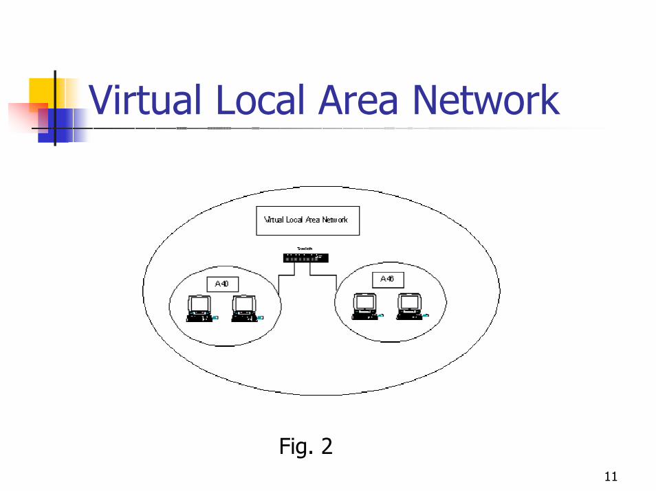
Iteration 2 (Elaboration)System Architecture – see the Virtual Local Area Netwok (Fig.2)Software ArchitectureDatabase DesignBuild 1 – first basic version of the softwareConfiguration Management PlanTest Plan
11
Virtual Local Area Network
Fig. 2
12
Designing system securityStepsSteps:
Safety analysisSafety policySafety planActions plan.
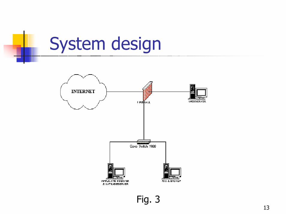
The resulting system design is illustrated in Fig.3 (next slide)
13
System design
Fig. 3

14
Iteration 3 (Construction)
Software and system implementationRefining of Software Architecture to cover all use casesBuild 2: a working base, to use in order to improve most functionalityBuild 3: a fully functional version of the ESTIMATOR system
15
System implementation (1)Computers used:1. Application Server & Database Server2. Primary Domain Controller (PDC) & Database
Backup3. Firewall (WinRoute Pro)4. Web Server.
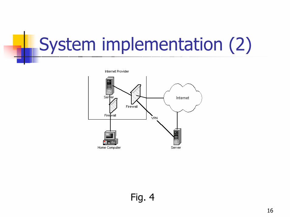
A Virtual Private Network was installed and configured on the Application Server computer in order to allow remote access to the system files at the institution, see Fig.4 (next slide).
16
System implementation (2)
Fig. 4
17
Iteration 4 (Construction)Implementation of remaining use casesDatabase implementation on MySQL DB ServerDB Design updatedExecutable release of the ESTIMATOR system (Build 4)IOC Package: code, life-cycle documentation, demos.
18
III. Software estimation with use cases
Use cases are used to capture and express system behaviorTo each use case a use case realization is associated which is represented by analysis-level objects and sequence diagramsAn algorithm for estimating software development effort based on use cases is presented (see slides 19-21).

19

20

21

22
IV.Application of the Estimation Algorithm
Step 1 - Total Actors
The user lists the actors in the project. For each actor he determines the type: whether it is simple, average or complex. The criteria are:
Simple - the actor is another system with an interface towards the user's systemAverage - the actor is another system that interacts through a protocol Complex - the actor is a person interacting through a GUI.
The system gives each actor type a weight as follows:
Actor Weight
Simple 1
Average 2
Complex 3
23
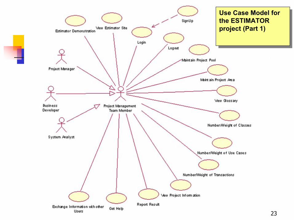
Use Case Model for the ESTIMATOR project (Part 1)
Use Case Model for the ESTIMATOR project (Part 1)
24
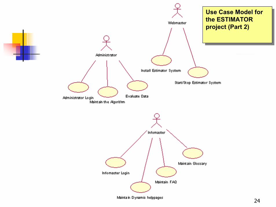
Use Case Model for the ESTIMATOR project (Part 2)
Use Case Model for the ESTIMATOR project (Part 2)

25
Total actors (ESTIMATOR example)
Actor Name Complexity Factor
Project management team member
Complex 3
Webmaster Simple 1
Administrator Average 2
Infomaster Average 2
Sum 8
Ta = 1*1 + 2*2 + 1*3 = 8
26
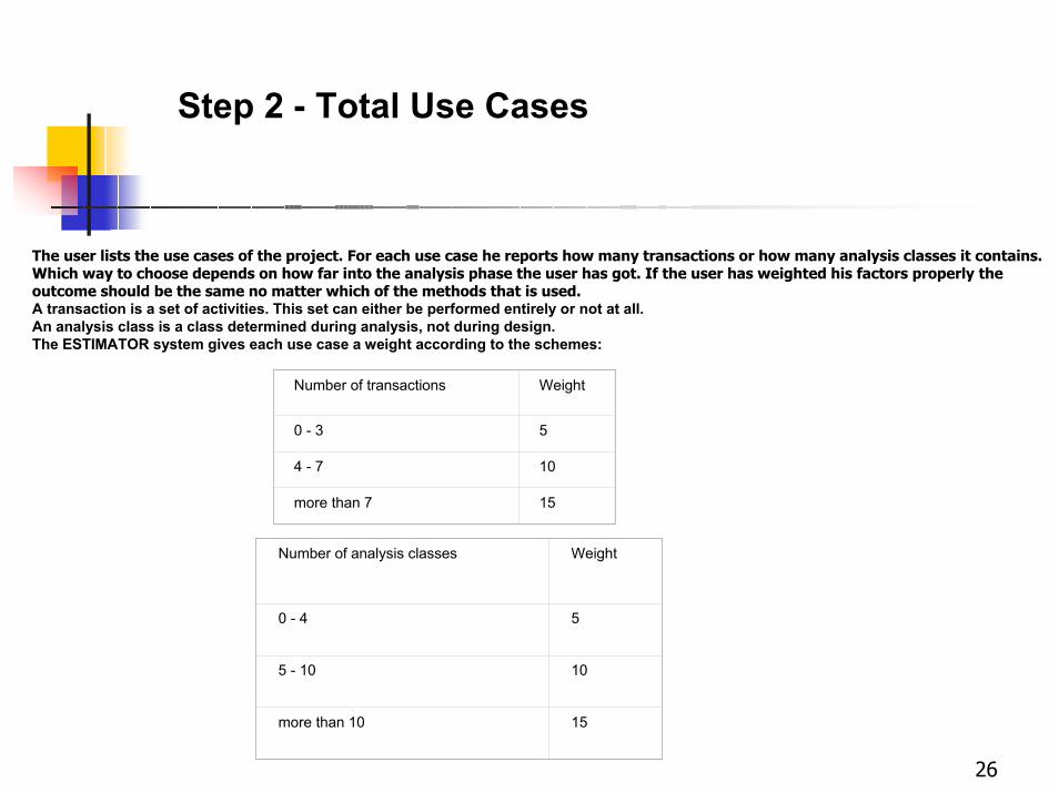
Step 2 - Total Use Cases
The user lists the use cases of the project. For each use case he reports how many transactions or how many analysis classes it contains. Which way to choose depends on how far into the analysis phase the user has got. If the user has weighted his factors properly the outcome should be the same no matter which of the methods that is used. A transaction is a set of activities. This set can either be performed entirely or not at all. An analysis class is a class determined during analysis, not during design.The ESTIMATOR system gives each use case a weight according to the schemes:
Number of transactions Weight
0 - 3 5
4 - 7 10
more than 7 15
Number of analysis classes Weight
0 - 4 5
5 - 10 10
more than 10 15
27
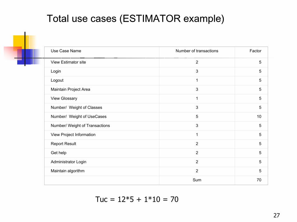
Total use cases (ESTIMATOR example)
Use Case Name Number of transactions Factor
View Estimator site 2 5
Login 3 5
Logout 1 5
Maintain Project Area 3 5
View Glossary 1 5
Number/ Weight of Classes 3 5
Number/ Weight of UseCases 5 10
Number/ Weight of Transactions 3 5
View Project Information 1 5
Report Result 2 5
Get help 2 5
Administrator Login 2 5
Maintain algorithm 2 5
Sum 70
Tuc = 12*5 + 1*10 = 70

28
Step 3 – Technical complexity of the project
The user has to go through a form and rate 13 factors, each of them from 0 to 5, where 0 means that the factor is irrelevant for this project, and 5 means that the factor is essential for this project.
After this is done the ESTIMATOR system multiplies all the ratings with a weight for each factor description.The result is given by the following expression:
TCF (Technical Complexity Factor) = 0.6 + (0.01 * Sum )

29
Technical complexity (ESTIMATOR example)
Factor contributing to complexity Rate from 0 -5
* weight
= Result
Distributed system 5 2 10
Response or throughput performance objectives
3 1 3
End-user efficiency (online) 5 1 5
Complex internal processing 3 1 3
Code must be reusable 1 1 1
Easy to install 3 0.5 1.5
Easy to use 5 0.5 2.5
Portable 3 2 6
Easy to change 4 1 4
Concurrent 3 1 3
Includes special security features 4 1 4
Provides direct access for third parties 5 1 5
Special user training facilities are required 4 1 4
Sum 52
TCF = 0.6 + (0.01 * 52 ) = 1.12

30
Step 4 – Efficiency of the project(Environmental factor)
Factor description Rate from 0 - 5 Rating description
Familiar with Rational Unified Process 0/no experience 3/average 5/expert
Application experience 0/no experience 3/average 5/expert
Object-oriented experience 0/no experience 3/average 5/expert
Lead analyst capability 0/no experience 3/average 5/expert
Motivation 0/no motivation in the project 3/average 5/high
Stable requirements 0/extremely unstable 3/average 5/unchanging
Part-time workers 0/no part-time technical staff 3/average 5/all
Difficult programming language 0/easy 3/average 5/very difficult
After this is done the ESTIMATOR system multiplies all the ratings with the weights for each factor. The result is given by the following expression:
EF (Environmental Factor) = 1.4 + (-0.03 * Sum )

31
Efficiency of the project (ESTIMATOR example)
Factor description Rate from 0 - 5 * Weight = Result
Familiar with Rational Unified Process 1 1.5 1.5
Application experience 3 0.5 1.5
Object-oriented experience 3 1 3
Lead analyst capability 2 0.5 1
Motivation 5 1 5
Stable requirements 3 2 6
Part-time workers 1 -1 -1
Difficult programming language 4 -1 -4
Sum 13
EF = 1.4 + (-0.03 * 13 ) = 1.01

32
Step 5 – Use case pointsNow the user has done his part. The ESTIMATOR system puts all the results from step 1-4 together. The result is called Use Case Points.
The ESTIMATOR example:
Result from weighting Actors 8.00
Result from weighting Use Cases 70.00
Result from weighting Technical Factors (TCF)
1.12
Result from weighting Environmental Factors (EF)
1.01
Use Case Points = (8 + 70) * 1.12 * 1.01 =
88.23

33
Step 6 – Project estimate
Factor description Rate from 0 -5
Number of ratings below 3
Familiar with Rational Unified Process 1 1
Application experience 3 0
Object-oriented experience 3 0
Lead analyst capability 2 1
Motivation 5 0
Stable requirements 3 0
Sum 2

34
Step 6 – Project estimate (cont.)
Factor description Rate from 0 -5
Number of ratings above 3
Part-time workers 1 0
Difficult programming language
4 1
Sum 1
Total Sum 3
35
Step 6 – Project estimate (cont.)
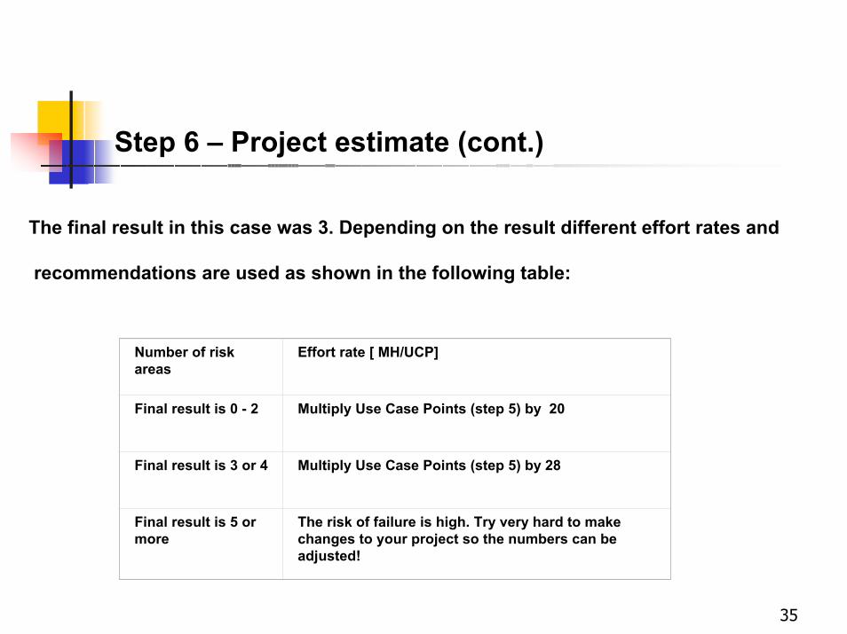
The final result in this case was 3. Depending on the result different effort rates and
recommendations are used as shown in the following table:
Number of risk areas
Effort rate [ MH/UCP]
Final result is 0 - 2 Multiply Use Case Points (step 5) by 20
Final result is 3 or 4 Multiply Use Case Points (step 5) by 28
Final result is 5 or more
The risk of failure is high. Try very hard to make changes to your project so the numbers can be adjusted!
36
Step 6 – Project estimate (cont.)
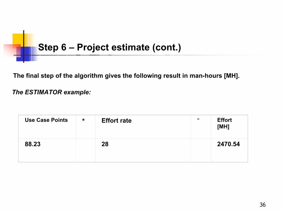
The final step of the algorithm gives the following result in man-hours [MH].
The ESTIMATOR example:
Use Case Points * Effort rate = Effort [MH]
88.23 28 2470.54
37
V. Conclusion
The paper focused on experimental results obtained in building an Internet-intranet solution for software system estimation based on use cases:
Development process for an operational software-hardware multi-tier Web Application System (WAS);Applicability of a use case-based effort estimation algorithm.
Theoretical foundations of MBASE and RUP model systems have been creatively applied in order to develop the application.

38
References