an introduction to coiled tubing
TRANSCRIPT
presents
History, Applications, and Benefits
ICoTA MissionTo enhance communication, gather technical expertise and promote safety, trainingcompetency and industry accepted practices within the coiled tubing industry.
An Introduction to Coiled Tubing
www.icota.com
What is CT? ........................................................................................................... 1Key Elements of a CT Unit .......................................................................................................... 1Well Control Equipment ............................................................................................................... 3CT Benefits ................................................................................................................................. 4CT Field Applications ................................................................................................................... 4
History ................................................................................................................... 5CT Origin .................................................................................................................................... 5Early CT Equipment .................................................................................................................... 5Evolution of CT Equipment .......................................................................................................... 5
The Business ........................................................................................................ 9Growth of the CT Service Fleet ................................................................................................... 9New CT Markets/Field Applications ........................................................................................... 10CT Service Providers ............................................................................................................... 10
The Tubing ........................................................................................................... 11Raw Material for CT .................................................................................................................. 11CT Manufacturing ..................................................................................................................... 11CT Mechanical Performance .................................................................................................... 12CT String Design ...................................................................................................................... 13CT Inspection Tools .................................................................................................................. 14Repairs and Splicing ................................................................................................................. 14Addressing Offshore Weight and Space Limitations .................................................................... 15Extending the CT Operating Envelope – Downhole Tractors .................................................... 15Alternatives to Carbon Steel CT ................................................................................................ 16
Workover & Completion Applications ................................................................ 17Common CT Workover Applications .......................................................................................... 17Removing Sand or Fill from a Wellbore ..................................................................................... 17Unloading a Well with Nitrogen .................................................................................................. 18Fracturing/Acidizing a Formation ............................................................................................... 18
Drilling Applications ............................................................................................ 19Non-Directional Wells ................................................................................................................ 19Directional Wells ........................................................................................................................ 19Wellbore Hydraulics and Drilling Fluids ..................................................................................... 20Overbalanced CTD .................................................................................................................. 20Underbalanced CTD ................................................................................................................ 21
Pipeline Applications .......................................................................................... 22Land ......................................................................................................................................... 22Offshore .................................................................................................................................... 22Limitations ................................................................................................................................. 22Overcoming Pipeline Drag Limitations ....................................................................................... 23
Permanent Installations ....................................................................................... 24Offshore Flowlines .................................................................................................................... 24Velocity Strings .......................................................................................................................... 25Control Lines ............................................................................................................................ 25
Nomenclature ...................................................................................................... 262005 ICoTA Board Members ............................................................................... 27Membership Application ..................................................................................... 28
The ICoTA website contains a wealth of additional Coiled Tubing information,including technical papers, the latest meeting notices, etc.
Please visit our website at: www.ICoTA.com
International Coiled Tubing Association
What is CT?Coiled Tubing (CT) has been defined as any continuously-milled tubular product manufactured inlengths that require spooling onto a take-up reel, during the primary milling or manufacturingprocess. The tube is nominally straightened prior to being inserted into the wellbore and is recoiledfor spooling back onto the reel. Tubing diameter normally ranges from 0.75 in. to 4 in., and singlereel tubing lengths in excess of 30,000 ft. have been commercially manufactured. Common CTsteels have yield strengths ranging from 55,000 PSI to 120,000 PSI.
KEY ELEMENTS OF A CT UNIT
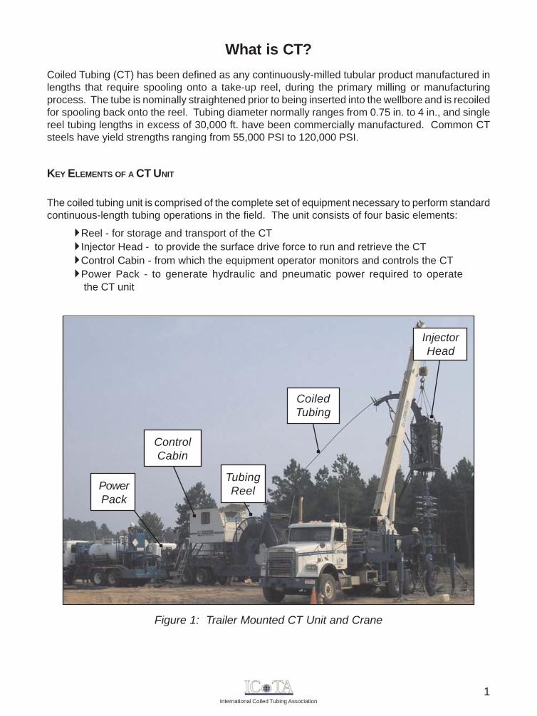
The coiled tubing unit is comprised of the complete set of equipment necessary to perform standardcontinuous-length tubing operations in the field. The unit consists of four basic elements:
Reel - for storage and transport of the CTInjector Head - to provide the surface drive force to run and retrieve the CTControl Cabin - from which the equipment operator monitors and controls the CTPower Pack - to generate hydraulic and pneumatic power required to operate the CT unit
Figure 1: Trailer Mounted CT Unit and Crane
ControlCabin
TubingReel
CoiledTubing
InjectorHead
PowerPack
1
International Coiled Tubing Association
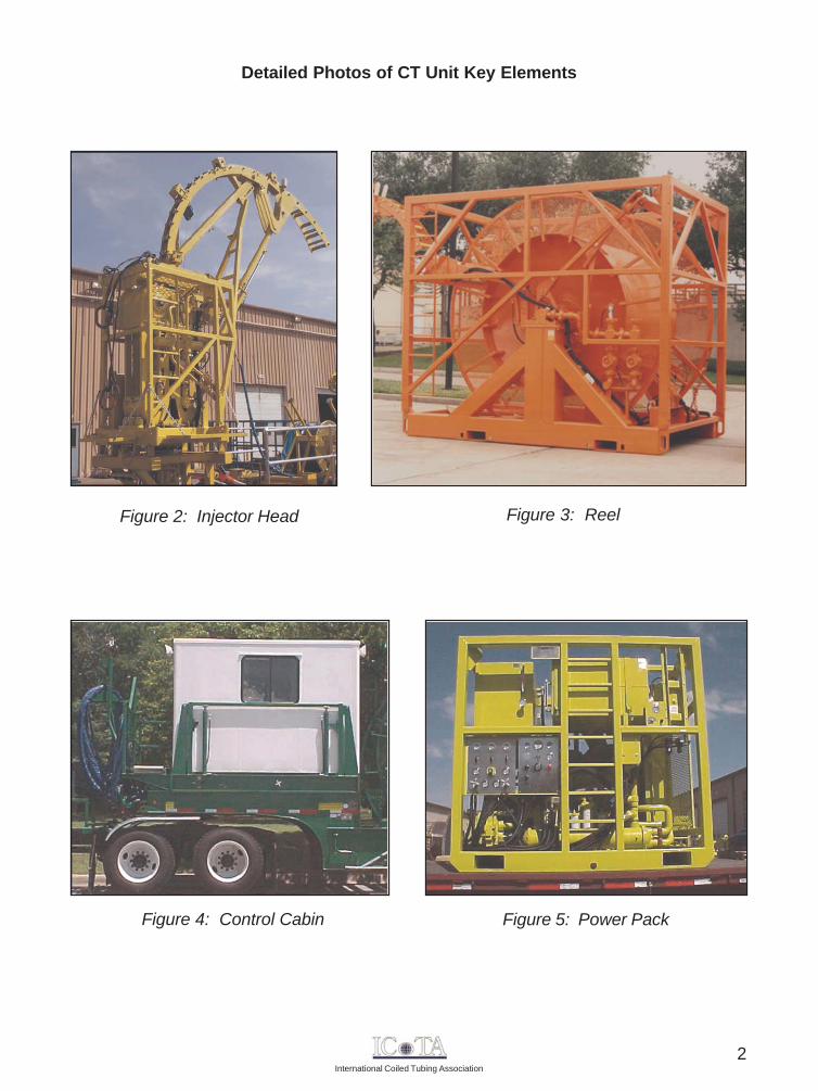
Detailed Photos of CT Unit Key Elements
Figure 2: Injector Head
Figure 4: Control Cabin
Figure 3: Reel
Figure 5: Power Pack
2
International Coiled Tubing Association
WELL CONTROL EQUIPMENT
Proper well control equipment is another key component of CT operations, given that a majority ofthese operations are performed in the presence of surface wellhead pressure. Typical CT wellcontrol equipment consists of a BOP topped with a stripper (high pressure CT units have twostrippers and additional BOP components). All components must be rated for the maximumwellhead pressure and temperature possible for the planned field operation.
The stripper (sometimes referred to as a packoff or stuffing box) provides the primary operationalseal between pressurized wellbore fluids and the surface environment. It is physically locatedbetween the BOP and the injector head. The stripper provides a dynamic seal around the CTduring tripping and a static seal around the CT when there is no movement. The latest style ofstripper devices are designed with a side door, that permits easy access and replacement of thesealing elements, with the CT in place.
The BOP is situated beneath the stripper, and can also be used to contain wellbore pressure. ACT BOP is designed specifically for CT operations. It consists of several pairs of rams, with eachram designed to perform a specific function. The number and type of ram pairs in a BOP aredetermined by the BOP configuration: single, double, or quad. A quad system is commonly usedin most operations.
The four BOP rams, from top to bottom and their associated functions are:
Blind ram - seals the wellbore when the CT is out of the BOP
Shear ram - used to cut the CT
Slip ram - supports the CT weight hanging below it (some are bi-directional andprevent the CT from moving upward)
Pipe ram - seals around the hanging CT
Standard CT BOPs also contain two equalizing ports, one on each side of the sealing rams. Italso has a side outlet between the slip and shear rams. This outlet can be used as a safety killline. BOPs are available in a range of sizes, and normally follow the API flange sizes.
3
International Coiled Tubing Association
Traditional Applications
Well UnloadingCleanoutsAcidizing/StimulationVelocity StringsFishingTool ConveyanceWell Logging (real-time & memory)Setting/Retrieving Plugs
Growth Applications
CT DrillingFracturingSubseaDeeper WellsPipeline/Flowline
CT BENEFITS
While the initial development of coiled tubing was spurred by the desire to work on live wellbores,speed and economy have emerged as key advantages for application of CT. In addition, therelatively small footprint and short rig-up time make CT even more attractive for drilling and workoverapplications.
Some of the key benefits associated with the use of CT technology are as follows:
Safe and efficient live well interventionRapid mobilization and rig-upAbility to circulate while RIH/POOHReduced trip time, resulting in less production downtimeReduced crew/personnel requirementsCost may be significantly reduced
Coiled tubing can also be fitted with internal electrical conductors or hydraulic conduits, whichenables downhole communication and power functions to be established between the BHA andsurface. In addition, modern CT strings provide sufficient rigidity and strength to be pushed/pulledthrough highly deviated or horizontal wellbores. This enables successful execution of downholeoperations that would be impossible to perform with conventional wireline approaches, or wouldbe cost prohibitive if performed by jointed-pipe.
CT FIELD APPLICATIONS
The use of CT has continued to grow beyond the typical well cleanout and acid stimulationapplication. This growth can be attributed to a multitude of factors, including advances in CTtechnology and materials as well as the increased emphasis on wellbores containing a horizontaland/or highly-deviated section.
The CT application list (below) is provided as a "thought-provoker", to illustrate additional operationswhere CT could be of benefit in your future field work.
4
International Coiled Tubing Association
HistoryThe development of coiled tubing as we know it today dates back to the early 1960's, and it hasbecome an integral component of many well service and workover applications. While well service/workover applications still account for more than 75% of CT use, technical advancements haveincreased the utilization of CT in both drilling and completion applications.
The ability to perform remedial work on a live well was the key driver associated with the developmentof CT. To accomplish this feat, three technical challenges had to be overcome:
A continuous conduit capable of being inserted into the wellbore (CT string).A means of running and retrieving the CT string into or out of the wellbore whileunder pressure (injector head).A device capable of providing a dynamic seal around the tubing string(stripper or packoff device).
CT ORIGIN
Prior to the Allied invasion in 1944, British engineers developed and produced very long, continuouspipelines for transporting fuel from England to the European Continent to supply the Allied armies.The project was named operation "PLUTO", an acronym for "Pipe Lines Under The Ocean", andinvolved the fabrication and laying of several pipelines across the English Channel. The successfulfabrication and spooling of continuous flexible pipeline provided the foundation for additional technicaldevelopments that eventually led to the tubing strings used today by the CT industry.
In 1962, the California Oil Company and Bowen Tools developed the first fully functional CT unit,for the purpose of washing out sand bridges in wells.
EARLY CT EQUIPMENT
The first injector heads operated on the principle of two vertical, contra-rotating chains. Thisdesign is still used in the majority of CT units today. The stripper was a simple, annular-typesealing device that could be hydraulically activated to seal around the tubing at relatively low wellheadpressures. The tubing string used for the initial trials was fabricated by butt-welding 50 ft. sectionsof 1 3/8 in. OD pipe into a 15,000 ft. string and spooling it onto a reel with a 9 ft. diameter core.
EVOLUTION OF CT EQUIPMENT
Throughout the late 1960's and into the 1970's, both Bowen Tools and Brown Oil Tools continuedto improve their designs to accommodate CT up to 1 in. OD. By the mid-1970's, more than 200 ofthe original-design CT units were in service. By the late 1970's, several new equipmentmanufacturing companies (Uni-Flex Inc., Otis Engineering, and Hydra Rig Inc.) also startedinfluencing improved injector head design.
5
International Coiled Tubing Association
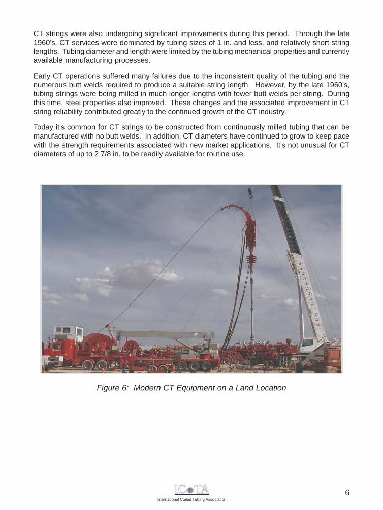
Figure 6: Modern CT Equipment on a Land Location
CT strings were also undergoing significant improvements during this period. Through the late1960's, CT services were dominated by tubing sizes of 1 in. and less, and relatively short stringlengths. Tubing diameter and length were limited by the tubing mechanical properties and currentlyavailable manufacturing processes.
Early CT operations suffered many failures due to the inconsistent quality of the tubing and thenumerous butt welds required to produce a suitable string length. However, by the late 1960's,tubing strings were being milled in much longer lengths with fewer butt welds per string. Duringthis time, steel properties also improved. These changes and the associated improvement in CTstring reliability contributed greatly to the continued growth of the CT industry.
Today it's common for CT strings to be constructed from continuously milled tubing that can bemanufactured with no butt welds. In addition, CT diameters have continued to grow to keep pacewith the strength requirements associated with new market applications. It's not unusual for CTdiameters of up to 2 7/8 in. to be readily available for routine use.
6
International Coiled Tubing Association
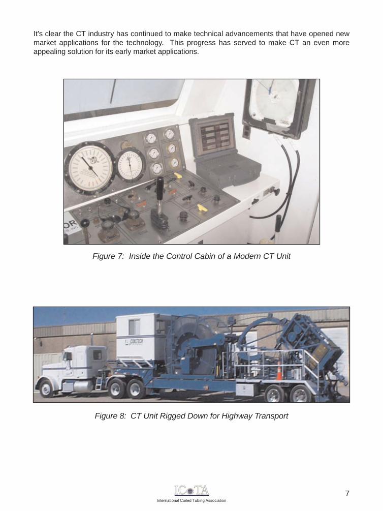
Figure 7: Inside the Control Cabin of a Modern CT Unit
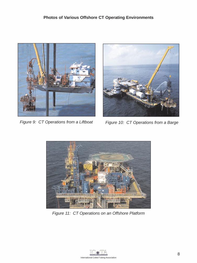
Figure 8: CT Unit Rigged Down for Highway Transport
It's clear the CT industry has continued to make technical advancements that have opened newmarket applications for the technology. This progress has served to make CT an even moreappealing solution for its early market applications.
7
International Coiled Tubing Association
Photos of Various Offshore CT Operating Environments
Figure 9: CT Operations from a Liftboat Figure 10: CT Operations from a Barge
Figure 11: CT Operations on an Offshore Platform
8
International Coiled Tubing Association
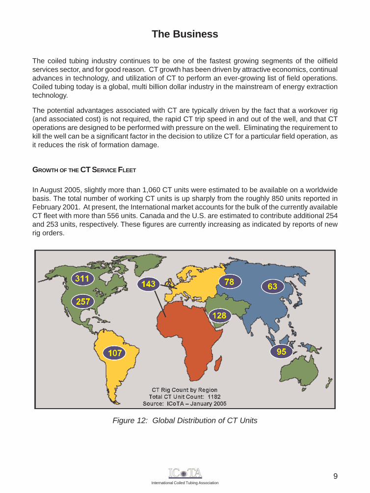
Figure 12: Global Distribution of CT Units
The Business
The coiled tubing industry continues to be one of the fastest growing segments of the oilfieldservices sector, and for good reason. CT growth has been driven by attractive economics, continualadvances in technology, and utilization of CT to perform an ever-growing list of field operations.Coiled tubing today is a global, multi billion dollar industry in the mainstream of energy extractiontechnology.
The potential advantages associated with CT are typically driven by the fact that a workover rig(and associated cost) is not required, the rapid CT trip speed in and out of the well, and that CToperations are designed to be performed with pressure on the well. Eliminating the requirement tokill the well can be a significant factor in the decision to utilize CT for a particular field operation, asit reduces the risk of formation damage.
GROWTH OF THE CT SERVICE FLEET
In August 2005, slightly more than 1,060 CT units were estimated to be available on a worldwidebasis. The total number of working CT units is up sharply from the roughly 850 units reported inFebruary 2001. At present, the International market accounts for the bulk of the currently availableCT fleet with more than 556 units. Canada and the U.S. are estimated to contribute additional 254and 253 units, respectively. These figures are currently increasing as indicated by reports of newrig orders.
9
International Coiled Tubing Association
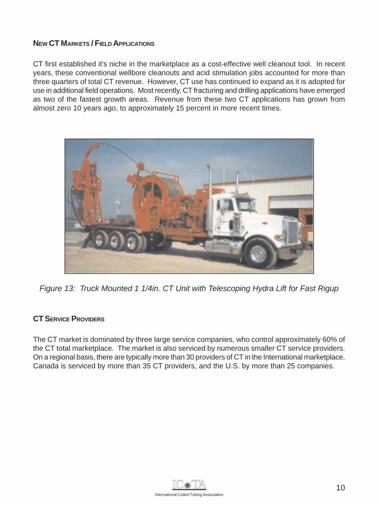
Figure 13: Truck Mounted 1 1/4in. CT Unit with Telescoping Hydra Lift for Fast Rigup
NEW CT MARKETS / FIELD APPLICATIONS
CT first established it's niche in the marketplace as a cost-effective well cleanout tool. In recentyears, these conventional wellbore cleanouts and acid stimulation jobs accounted for more thanthree quarters of total CT revenue. However, CT use has continued to expand as it is adopted foruse in additional field operations. Most recently, CT fracturing and drilling applications have emergedas two of the fastest growth areas. Revenue from these two CT applications has grown fromalmost zero 10 years ago, to approximately 15 percent in more recent times.
CT SERVICE PROVIDERS
The CT market is dominated by three large service companies, who control approximately 60% ofthe CT total marketplace. The market is also serviced by numerous smaller CT service providers.On a regional basis, there are typically more than 30 providers of CT in the International marketplace.Canada is serviced by more than 35 CT providers, and the U.S. by more than 25 companies.
10
International Coiled Tubing Association
The TubingThe manufacture of CT involves multiple steps, and the following contains an overview of the keycomponents involved in the manufacturing process.
RAW MATERIAL FOR CT
Virtually all CT in use today begins as large coils of low-alloy carbon-steel sheet. The coils can beup to 55 in. wide and weigh over 24 tons. The length of sheet in each coil depends upon the sheetthickness and ranges from 3,500 ft. for 0.087 in. gauge to 1,000 ft. for 0.250 in. gauge.
CT MANUFACTURING
At the end of 2003, two companies supplied all of the steel CT used by the petroleum industry.Quality Tubing, Inc. (QTI) and Precision Tube Technology (PTT) each have manufacturing facilitiesin Houston, TX. The first step in tube making is to slice flat strips from the roll of sheet steel, andthis step is usually performed by a company specializing in this operation. The strip's thicknessestablishes the CT wall thickness and the strip's width determines the OD of the finished CT.
The steel strips are then shipped to a CT mill for the next step in the manufacturing process. Themill utilizes bias welds to splice the flat strips together to form a single continuous strip of thedesired CT string length. The mechanical properties of the bias strip welds almost match theparent strip in the as-welded condition, and the profile of the weld evenly distributes stresses overa greater length of the CT. The CT mill then utilizes a series of rollers to gradually form the flat stripinto a round tube. The final set of rollers forces the two edges of the strip together inside a highfrequency induction welding machine that fuses the edges with a continuous longitudinal seam.This welding process does not use any filler material, but leaves behind a small bead of steel(weld flash) on both sides of the strip.
The mill removes the external bead with a scarfing tool to provide a smooth OD. The weld seamis then normalized using highly localized induction heating. Next, the weld seam is allowed to coolprior to water cooling. Full tube eddy current or weld seam ultrasonic inspection may also beperformed, depending upon the mill setup. The tubing then passes through sizing rollers thatreduce the tube OD slightly to maintain the specified manufacturing diameter tolerances. A fullbody stress relief treatment is then performed to impart the desired mechanical properties to thesteel. Subsequent to the CT being wound on a shipping reel, the mill flushes any loose materialfrom the finished CT string.
Raw Material for CTCT ManufacturingCT Mechanical PerformanceCT String Design
CT Inspection ToolsRepairs and SplicingAlternatives to Carbon Steel CT
11
International Coiled Tubing Association
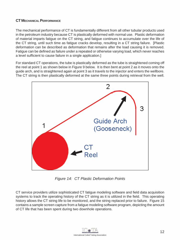
Figure 14: CT Plastic Deformation Points
CT MECHANICAL PERFORMANCE
The mechanical performance of CT is fundamentally different from all other tubular products usedin the petroleum industry because CT is plastically deformed with normal use. Plastic deformationof material imparts fatigue on the CT string, and fatigue continues to accumulate over the life ofthe CT string, until such time as fatigue cracks develop, resulting in a CT string failure. [Plasticdeformation can be described as deformation that remains after the load causing it is removed.Fatigue can be defined as failure under a repeated or otherwise varying load, which never reachesa level sufficient to cause failure in a single application.]
For standard CT operations, the tube is plastically deformed as the tube is straightened coming offthe reel at point 1 as shown below in Figure 9 below. It is then bent at point 2 as it moves onto theguide arch, and is straightened again at point 3 as it travels to the injector and enters the wellbore.The CT string is then plastically deformed at the same three points during retrieval from the well.
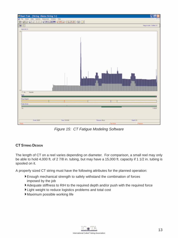
CT service providers utilize sophisticated CT fatigue modeling software and field data acquisitionsystems to track the operating history of the CT string as it is utilized in the field. This operatinghistory allows the CT string life to be monitored, and the string replaced prior to failure. Figure 15contains a sample screen capture from a fatigue modeling software program, depicting the amountof CT life that has been spent during two downhole operations.
12
International Coiled Tubing Association
CT STRING DESIGN
The length of CT on a reel varies depending on diameter. For comparison, a small reel may onlybe able to hold 4,000 ft. of 2 7/8 in. tubing, but may have a 15,000 ft. capacity if 1 1/2 in. tubing isspooled on it.
A properly sized CT string must have the following attributes for the planned operation:
Enough mechanical strength to safely withstand the combination of forcesimposed by the jobAdequate stiffness to RIH to the required depth and/or push with the required forceLight weight to reduce logistics problems and total costMaximum possible working life
Figure 15: CT Fatigue Modeling Software
13
International Coiled Tubing Association
Optimizing the design of a CT string to simultaneously meet the criteria shown above for a givenCT operation requires a sophisticated CT simulator and numerous iterations with proposed stringdesigns. CT strings designed in this manner usually will contain multiple sections of differing wallthickness. Often called "tapered strings", the wall thickness does not necessarily taper smoothlyfrom thick to thin (top to bottom). Instead, the wall thickness will vary according to the position inthe string. However, the OD of the string will remain constant.
The simplest method of designing a CT string considers only the wall thickness necessary at agiven location for the required mechanical strength and the total weight of the string. This methodassumes the open-ended CT string is hanging vertically in a fluid with the buoyed weight of thetubing being the only force acting on the string. Starting at the bottom of the string and working up,the designer selects the wall thickness at the top of each section that provides sufficient tensileforce at that location.
CT INSPECTION TOOLS
In addition to the practical reason for determining whether CT can safely pass through the surfaceequipment and be gripped properly by the injector, real-time measurements of tubing geometryare crucial for avoiding disastrous failures. To determine the suitability of a CT string for proposedoperation, one must determine if:
1. The stresses in the wall of the tubing caused by pressure and axial forces will exceed the yield stress of the material, and
2. The accumulated fatigue in any segment of the string will exceed a predeterminedsafe limit during the course of the operation.
Tubing geometry has a direct, significant effect on both issues.
Multiple tools capable of measuring external CT geometry have been used in the CT industry.These tools measure the tubing OD on several radials at a given cross section to determine theovality and diameter of the CT. More recently, several "full-body" CT inspection tools, with theability to detect tubing wall flaws as well as providing tubing wall thickness and geometrymeasurements, have been utilized. Real-time inspection systems are being used during offshoreoperations to assure total integrity of the coiled tubing.
REPAIRS AND SPLICING
The only acceptable method of repairing mechanical or corrosion damage to a CT string is tophysically remove the bad section of tubing and rejoin the ends with a temporary or permanentsplice.
A temporary splice consists of a mechanical connection that is formed with a tube-tube connector.This type of connection is typically not used for prolonged operations during a CT job, but rather asan emergency repair to allow the CT string to be pulled out of the hole.
14

International Coiled Tubing Association
However, connector technology continues to evolve and there are certain situations whereconnectors are used, such as to connect the tool string to the end of the CT. There are threegeneral types of connectors, including the grapple, setscrew/dimple, and roll-on connector.Connector selection is based on the particular operation to be performed, as each type incorporatesunique features that make it best-suited for a given application.
Only butt welds are possible for field welding repair of CT strings, with TIG welding being thepreferred method for permanent repair of CT work strings. The low heat input and the slowdeposition rate of this technique make it ideal for use with CT. The CT industry has three generallyaccepted TIG welding techniques:
Manually, with hand-held toolsSemi-automatically, with manual preparation with an automatic orbital welderFully-automatically, with a robotic orbital welder
All three methods can produce high quality welds. However, even the best repair weld has nomore than 50% of the fatigue life of the virgin tubing.
ADDRESSING OFFSHORE WEIGHT AND SPACE LIMITATIONS
CT operations on many offshore platforms are constrained by the lifting capacity of the crane, aswell as deck loading and space limitations. A loaded CT reel is typically the heaviest component ofthe CT system. Various solutions to address this issue have been successfully implemented inthe field, including:
1. Disassembling the CT equipment into the smallest, lightest lifts possible, andreassembling the equipment on the platform.
2. Cut the CT string into sections, spool the sections onto lightweight shipping reels,lift the reels onto the platform, then reconnect the sections on the platform.
3. Use a barge or jackup with a heavy-lift crane to hoist all of the CT equipmentonto the platform
4. Lift the CT unit, minus the CT string, onto the platform. Then spool the CT string ontothe work reel from a loaded reel on a floating vessel.
5. Install only the CT injector on the wellhead, leaving the CT reel and other CTunit components on a barge, workboat, or jackup, positioned alongside the platform.
The first four options can be applied where crane lift capacity is the controlling factor. Option 2 hasbeen applied successfully numerous times in the North Sea, and requires high quality CT weldingservices to be available. Options 3-5 require more equipment and personnel versus that of typicalCT operations, with an associated increase in the cost of the CT operation. Option 3 is rarelyused, due to the high cost and scarcity of floating cranes.
EXTENDING THE CT OPERATING ENVELOPE - DOWNHOLE TRACTORS
In some applications, such as wellbores with long horizontal sections, the inherit strength of theCT may not be adequate for the intended downhole task or CT lockup may prevent the CT stringfrom being able to reach the desired depth.
15
International Coiled Tubing Association
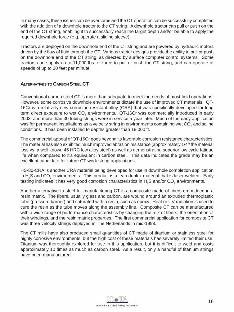
In many cases, these issues can be overcome and the CT operation can be successfully completedwith the addition of a downhole tractor to the CT string. A downhole tractor can pull or push on theend of the CT string, enabling it to successfully reach the target depth and/or be able to apply therequired downhole force (e.g. operate a sliding sleeve).
Tractors are deployed on the downhole end of the CT string and are powered by hydraulic motorsdriven by the flow of fluid through the CT. Various tractor designs provide the ability to pull or pushon the downhole end of the CT string, as directed by surface computer control systems. Sometractors can supply up to 11,000 lbs. of force to pull or push the CT string, and can operate atspeeds of up to 30 feet per minute.
ALTERNATIVES TO CARBON STEEL CT
Conventional carbon steel CT is more than adequate to meet the needs of most field operations.However, some corrosive downhole environments dictate the use of improved CT materials. QT-16Cr is a relatively new corrosion resistant alloy (CRA) that was specifically developed for longterm direct exposure to wet CO2 environments. QT-16Cr was commercially introduced in early2003, and more than 30 tubing strings were in service a year later. Much of the early applicationwas for permanent installations as a velocity string in environments containing wet CO2 and salineconditions. It has been installed to depths greater than 18,000 ft.
The commercial appeal of QT-16Cr goes beyond its favorable corrosion resistance characteristics.The material has also exhibited much improved abrasion resistance (approximately 1/4th the materialloss vs. a well known 45 HRC low alloy steel) as well as demonstrating superior low cycle fatiguelife when compared to it's equivalent in carbon steel. This data indicates the grade may be anexcellent candidate for future CT work string applications.
HS-80-CRA is another CRA material being developed for use in downhole completion applicationin H2S and CO2 environments. This product is a lean duplex material that is laser welded. Earlytesting indicates it has very good corrosion characteristics in H2S and/or CO2 environments.
Another alternative to steel for manufacturing CT is a composite made of fibers embedded in aresin matrix. The fibers, usually glass and carbon, are wound around an extruded thermoplastictube (pressure barrier) and saturated with a resin, such as epoxy. Heat or UV radiation is used tocure the resin as the tube moves along the assembly line. Composite CT can be manufacturedwith a wide range of performance characteristics by changing the mix of fibers, the orientation oftheir windings, and the resin matrix properties. The first commercial application for composite CTwas three velocity strings deployed in The Netherlands in mid-1998.
The CT mills have also produced small quantities of CT made of titanium or stainless steel forhighly corrosive environments, but the high cost of these materials has severely limited their use.Titanium was thoroughly explored for use in this application, but it is difficult to weld and costsapproximately 10 times as much as carbon steel. As a result, only a handful of titanium stringshave been manufactured.
16
International Coiled Tubing Association
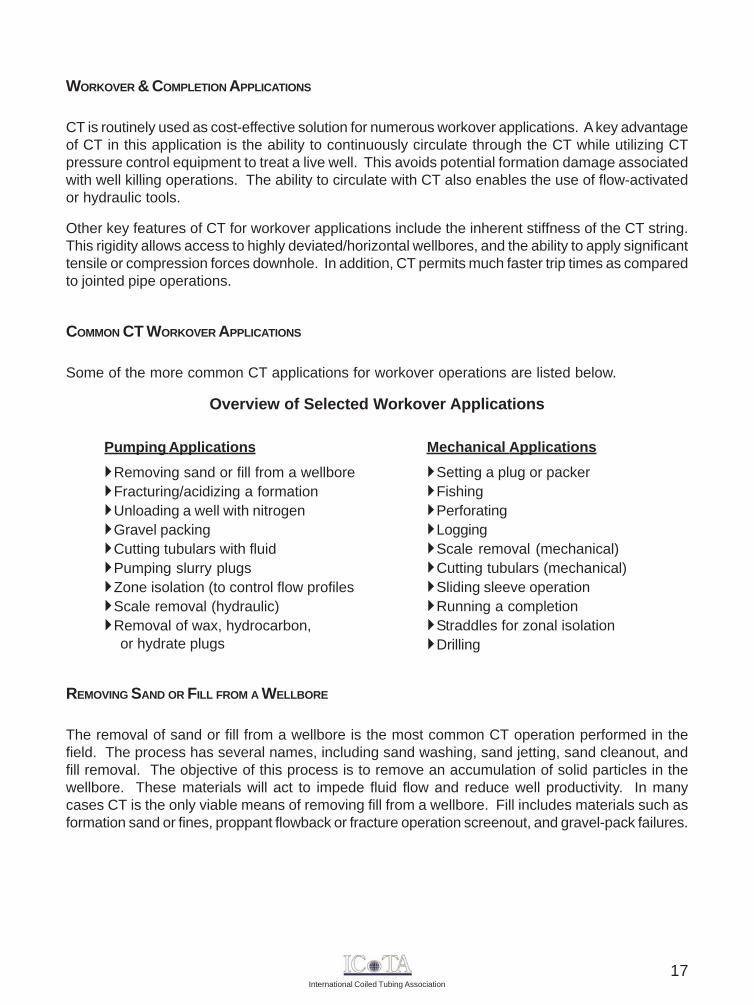
Mechanical ApplicationsSetting a plug or packerFishingPerforatingLoggingScale removal (mechanical)Cutting tubulars (mechanical)Sliding sleeve operationRunning a completionStraddles for zonal isolationDrilling
Pumping ApplicationsRemoving sand or fill from a wellboreFracturing/acidizing a formationUnloading a well with nitrogenGravel packingCutting tubulars with fluidPumping slurry plugsZone isolation (to control flow profilesScale removal (hydraulic)Removal of wax, hydrocarbon,
or hydrate plugs
WORKOVER & COMPLETION APPLICATIONS
CT is routinely used as cost-effective solution for numerous workover applications. A key advantageof CT in this application is the ability to continuously circulate through the CT while utilizing CTpressure control equipment to treat a live well. This avoids potential formation damage associatedwith well killing operations. The ability to circulate with CT also enables the use of flow-activatedor hydraulic tools.
Other key features of CT for workover applications include the inherent stiffness of the CT string.This rigidity allows access to highly deviated/horizontal wellbores, and the ability to apply significanttensile or compression forces downhole. In addition, CT permits much faster trip times as comparedto jointed pipe operations.
COMMON CT WORKOVER APPLICATIONS
Some of the more common CT applications for workover operations are listed below.
Overview of Selected Workover Applications
REMOVING SAND OR FILL FROM A WELLBORE
The removal of sand or fill from a wellbore is the most common CT operation performed in thefield. The process has several names, including sand washing, sand jetting, sand cleanout, andfill removal. The objective of this process is to remove an accumulation of solid particles in thewellbore. These materials will act to impede fluid flow and reduce well productivity. In manycases CT is the only viable means of removing fill from a wellbore. Fill includes materials such asformation sand or fines, proppant flowback or fracture operation screenout, and gravel-pack failures.
17
International Coiled Tubing Association
The typical procedure involved in this application is to circulate a fluid through the CT while slowlypenetrating the fill with an appropriate jetting nozzle attached to the end of the CT string. Thisaction causes the fill material to become entrained in the circulating fluid flow, and is subsequentlytransported out of the wellbore through the CT/production tubing annulus. Where consolidated fillis present, the procedure may require the assistance of a downhole motor and bit or impact drill.
An alternative fill removal approach is to pump down the CT/production tubing annulus and allowthe returns to be transported to surface within the CT string. This procedure, called reversecirculation, can be very useful for removing large quantities of particulate, such as frac sand, fromthe wellbore. It may also be applied when a particular wellbore configuration precludes annularvelocities sufficient to lift the fill material. Reverse circulation is suitable only for dead wells.
UNLOADING A WELL WITH NITROGEN
The process of using CT to unload a well with nitrogen is a quick and cost-effective method usedto regain sustained production. A typical field scenario consists of a wellbore that has developeda fluid column with sufficient hydrostatic pressure to prevent the reservoir fluid from flowing intothe wellbore. Displacement of some of this wellbore fluid with nitrogen reduces the hydrostatichead, and this reduction of BHP allows the reservoir fluid to again flow naturally into the wellbore.If the wellbore conditions are suitable (pressure, fluid phase mixture and flow rate), production willcontinue after nitrogen pumping ceases.
There are numerous benefits associated with the use of CT for a nitrogen kickoff operation. Therate and depth of the nitrogen injection can be adjusted to fit a wide range of field conditions. Theprocedure also provides a ready source of uncontaminated production fluid samples (oil, formationwater). And, the procedure is extremely simple from an operational standpoint, as only a smallamount of equipment and a limited number of field personnel are necessary.
FRACTURING / ACIDIZING A FORMATION
This CT application has experienced significant growth in recent years, and provides severaladvantages versus conventional formation treatment techniques. In particular, CT provides theability to quickly move in and out of the hole (or be quickly repositioned) when fracturing multiplezones in a single well. CT also provides the ability to facture or accurately spot the treatment fluidto ensure complete coverage of the zone of interest. When used in conjunction with an appropriatediversion technique, more uniform treating of long target zones can be achieved. This is particularlyimportant in horizontal wellbores. At the end of the formation treating operation, CT can be used toremove any sand plugs used in the treating process, and to lift the well to be placed on production.
One of the earlier concerns with CT fracturing was the erosion effects that occur when proppantis pumped during the fracturing operation and the resulting impact on CT string life. An ultrasonicthickness (UT) gauge is now used on location to measure CT thickness during the job. Data fromthese UT measurements can be used to adjust the CT fatigue models, and to accurately monitorremaining CT string life.
18
International Coiled Tubing Association
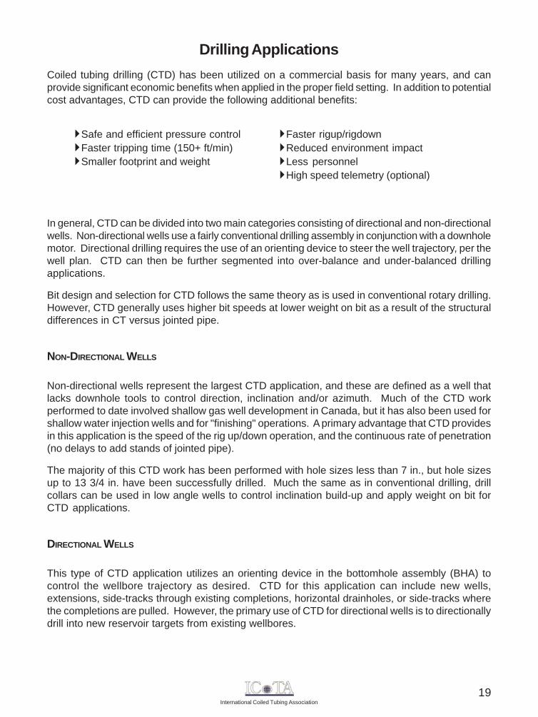
Drilling ApplicationsCoiled tubing drilling (CTD) has been utilized on a commercial basis for many years, and canprovide significant economic benefits when applied in the proper field setting. In addition to potentialcost advantages, CTD can provide the following additional benefits:
In general, CTD can be divided into two main categories consisting of directional and non-directionalwells. Non-directional wells use a fairly conventional drilling assembly in conjunction with a downholemotor. Directional drilling requires the use of an orienting device to steer the well trajectory, per thewell plan. CTD can then be further segmented into over-balance and under-balanced drillingapplications.
Bit design and selection for CTD follows the same theory as is used in conventional rotary drilling.However, CTD generally uses higher bit speeds at lower weight on bit as a result of the structuraldifferences in CT versus jointed pipe.
NON-DIRECTIONAL WELLS
Non-directional wells represent the largest CTD application, and these are defined as a well thatlacks downhole tools to control direction, inclination and/or azimuth. Much of the CTD workperformed to date involved shallow gas well development in Canada, but it has also been used forshallow water injection wells and for "finishing" operations. A primary advantage that CTD providesin this application is the speed of the rig up/down operation, and the continuous rate of penetration(no delays to add stands of jointed pipe).
The majority of this CTD work has been performed with hole sizes less than 7 in., but hole sizesup to 13 3/4 in. have been successfully drilled. Much the same as in conventional drilling, drillcollars can be used in low angle wells to control inclination build-up and apply weight on bit forCTD applications.
DIRECTIONAL WELLS
This type of CTD application utilizes an orienting device in the bottomhole assembly (BHA) tocontrol the wellbore trajectory as desired. CTD for this application can include new wells,extensions, side-tracks through existing completions, horizontal drainholes, or side-tracks wherethe completions are pulled. However, the primary use of CTD for directional wells is to directionallydrill into new reservoir targets from existing wellbores.
Faster rigup/rigdownReduced environment impactLess personnelHigh speed telemetry (optional)
Safe and efficient pressure controlFaster tripping time (150+ ft/min)Smaller footprint and weight
19
International Coiled Tubing Association
Directional drilling with CT has some fundamental differences compared to conventional rotarydrilling techniques. One of the basic differences is the need for an orienting device to control thewell trajectory, since CT cannot rotate. Orienting devices control hole direction by rotating a benthousing to a particular orientation (toolface) or controls the side loading at the bit to push theassembly in a particular direction. This control over the BHA provides directional control for CTDapplications.
A steering tool is used to measure inclination, azimuth, and tool face orientation. Two basic typesof steering tools are used for directional drilling with CT. Electric steering tools are used inconjunction with a cable inside the CT to transmit data to surface. Mud pulse tools comprise thesecond type of steering device for CTD applications. Mud pulse steering tools transmit data to thesurface by generating pressure pulses in the mud.
In addition to orientation and steering devices, some BHAs utilized for CTD are equipped withadditional measurement tools, including gamma ray, casing collar locator, accelerometers (shockload measurements), pressure (internal and annulus) and weight on bit.
WELLBORE HYDRAULICS AND WELLBORE FLUIDS
There are some key fluid design parameters to keep in mind for CTD applications versus traditionalrotary drilling. For example, all CTD operations require the fluid to travel through the entire tubingstring regardless of the current drilling depth. In addition, the frictional pressure loss for CT on thereel is considerably larger than for straight tubing. Thus, for optimum hydraulic performance, thedrilling fluid must behave as a low viscosity fluid while inside the CT, and as a high viscosity fluid inthe annulus (for efficient cuttings removal).
Another key difference associated with CTD is the absence of tubing rotation while drilling. Jointedpipe is rotated during conventional drilling operations, and this movement helps keep the drill cuttingssuspended in the drilling fluid, so they can be lifted to surface. Since the tube doesn't rotate inCTD applications, hole cleaning can be more challenging in heavily deviated/horizontal applications.This effect is partially offset by the smaller cuttings produced with CTD (higher RPM, lower weighton bit). In addition, special visco-elastic fluids have been developed for CTD, that change theirrheology according to the local shear rate, i.e., become more viscous in the annulus (lower shearrate) to improve cutting suspension.
OVERBALANCED CTD
As with conventional well drilling operations, the drilling fluid is used for controlling subsurfacepressure and the CTD drilling fluid systems are typically smaller versions of conventional systems.Conventional well control principles apply except that the CT string limits the fluid flow rate and thefrictional pressure loss varies with the ratio of tubing on/off the reel.
20
International Coiled Tubing Association
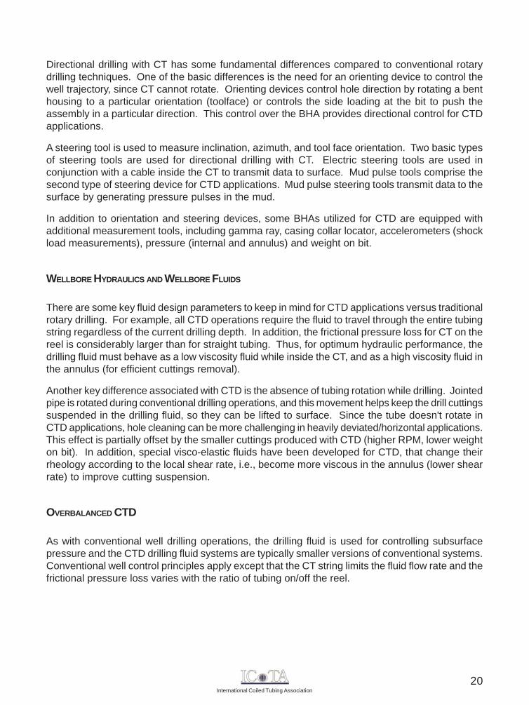
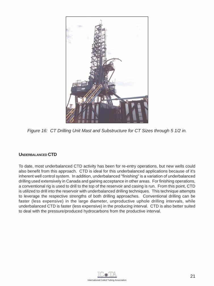
Figure 16: CT Drilling Unit Mast and Substructure for CT Sizes through 5 1/2 in.
UNDERBALANCED CTD
To date, most underbalanced CTD activity has been for re-entry operations, but new wells couldalso benefit from this approach. CTD is ideal for this underbalanced applications because of it'sinherent well control system. In addition, underbalanced "finishing" is a variation of underbalanceddrilling used extensively in Canada and gaining acceptance in other areas. For finishing operations,a conventional rig is used to drill to the top of the reservoir and casing is run. From this point, CTDis utilized to drill into the reservoir with underbalanced drilling techniques. This technique attemptsto leverage the respective strengths of both drilling approaches. Conventional drilling can befaster (less expensive) in the large diameter, unproductive uphole drilling intervals, whileunderbalanced CTD is faster (less expensive) in the producing interval. CTD is also better suitedto deal with the pressure/produced hydrocarbons from the productive interval.
21
International Coiled Tubing Association
Pipeline Applications
CT can be used as an effective tool for numerous pipeline applications, including:
Transportation of inspection toolsRemoving organic deposits and hydrate plugsRemoving sand or fillPlacing a patch or liner to repair minor leaksSetting temporary plugs
LAND
Land-based CT operations in pipelines are similar to CT operations in horizontal wellbores with afew notable exceptions. First, the injector head must supply all the force required to RIH with theCT. The lack of a vertical CT section means that none of the CT weight is available to push on theCT ahead of it. Second, the injector head must be oriented horizontally at the entrance to thepipeline. This requires a special mounting frame and an injector that will operate efficiently whilelying on its side. Finally, the injector head will be required to snub the CT into the pipeline duringthe entire RIH operation, and thus the weight measuring device (weight cell) must be configuredfor accurate measurement of snubbing forces.
OFFSHORE
CT operations in pipelines from an offshore platform are similar to operations in extended reachwellbores that kickoff at a shallow depth. The primary difference is that the path of the CT betweenthe injector and the conduit on the sea floor may include several short radius bends. These bendsimpart a high drag force, and increase the snubbing force requirement on the CT injector. Sincethe injector may have to snub the CT into the pipeline during most of the RIH phase of the operation,the CT weight measuring device (weight cell) must be configured for accurate snubbing forcemeasurement.
LIMITATIONS
Regardless of the operational environment (land vs. offshore), post-helical buckling lockup of theCT is typically the primary limiting factor for pipeline operations. Lockup limits both the CT'shorizontal reach into the pipeline, as well as the maximum available force that can be transmittedby the CT.
22
International Coiled Tubing Association
In addition, the radial clearance between the CT and the pipeline conduit is usually much largerwhen compared to standard wellbore operations. This effectively reduces the downhole criticalforce required to helically buckle the CT. Also, oil pipelines typically have an internal coating ofhighly viscous oil or wax that significantly increases the CT sliding friction coefficient. This excessivedrag against the CT can also reduce the length of CT that can be pushed into the pipeline prior tobuckling.
OVERCOMING PIPELINE DRAG LIMITATIONS
A common approach to reducing CT drag in conventional operations is the use of liquid frictionmodifiers to reduce the coefficient of friction between the CT and wellbore. This technique can beused in pipeline operations, and may provide a sufficient operating window to perform the desiredoperation.
Another typical approach utilized to overcome CT drag in pipelines is the addition of "skates" to theCT string at regular intervals. A skate resembles a rigid centralizer or stabilizer, with a roller on theend of each arm (blade). The skates serve to support the CT and prevent it from dragging againstthe inside of the pipeline. This effectively converts the drag from sliding friction to rolling friction.It's not uncommon for this approach to reduce the effective friction coefficient by 75%, whichallows the CT to be pushed much farther into the pipeline without experiencing lockup.
In addition to the use of skates, hydraulic "thrusters" can be used to successfully reach the desiredlength inside the pipeline. A thruster consists of jets aimed in a direction opposite to the desiredCT movement direction. This action applies a tensile force to the CT, and act to literally pull the CTstring along the pipeline. Providers of the thruster service claim that the combination of thrustersand skates can enable CT operations to be successfully performed in horizontal pipelines up tofive miles from the injector head point.
23
International Coiled Tubing Association
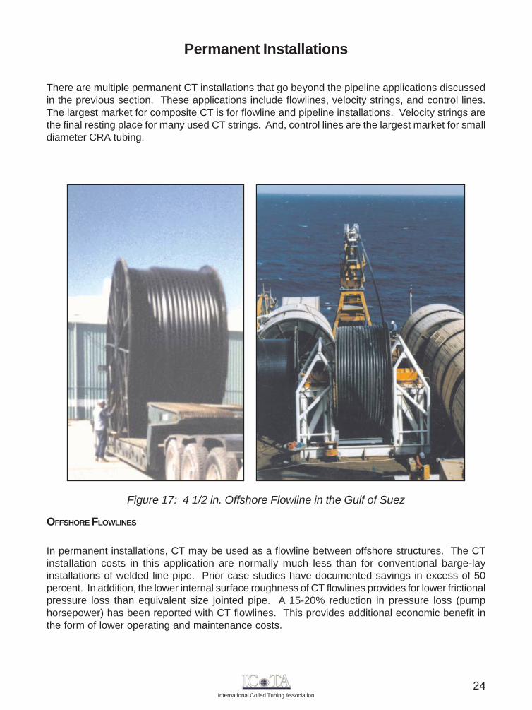
Figure 17: 4 1/2 in. Offshore Flowline in the Gulf of Suez
Permanent Installations
There are multiple permanent CT installations that go beyond the pipeline applications discussedin the previous section. These applications include flowlines, velocity strings, and control lines.The largest market for composite CT is for flowline and pipeline installations. Velocity strings arethe final resting place for many used CT strings. And, control lines are the largest market for smalldiameter CRA tubing.
OFFSHORE FLOWLINES
In permanent installations, CT may be used as a flowline between offshore structures. The CTinstallation costs in this application are normally much less than for conventional barge-layinstallations of welded line pipe. Prior case studies have documented savings in excess of 50percent. In addition, the lower internal surface roughness of CT flowlines provides for lower frictionalpressure loss than equivalent size jointed pipe. A 15-20% reduction in pressure loss (pumphorsepower) has been reported with CT flowlines. This provides additional economic benefit inthe form of lower operating and maintenance costs.
24
International Coiled Tubing Association
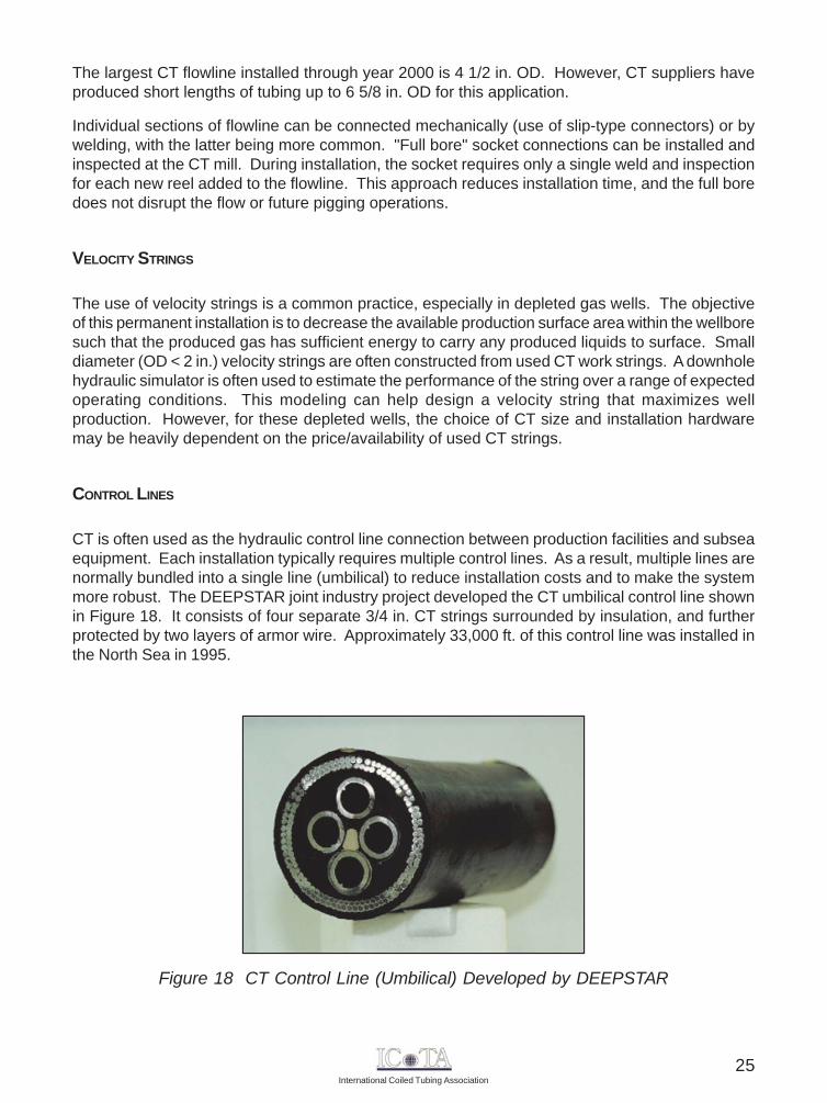
Figure 18 CT Control Line (Umbilical) Developed by DEEPSTAR
The largest CT flowline installed through year 2000 is 4 1/2 in. OD. However, CT suppliers haveproduced short lengths of tubing up to 6 5/8 in. OD for this application.
Individual sections of flowline can be connected mechanically (use of slip-type connectors) or bywelding, with the latter being more common. "Full bore" socket connections can be installed andinspected at the CT mill. During installation, the socket requires only a single weld and inspectionfor each new reel added to the flowline. This approach reduces installation time, and the full boredoes not disrupt the flow or future pigging operations.
VELOCITY STRINGS
The use of velocity strings is a common practice, especially in depleted gas wells. The objectiveof this permanent installation is to decrease the available production surface area within the wellboresuch that the produced gas has sufficient energy to carry any produced liquids to surface. Smalldiameter (OD < 2 in.) velocity strings are often constructed from used CT work strings. A downholehydraulic simulator is often used to estimate the performance of the string over a range of expectedoperating conditions. This modeling can help design a velocity string that maximizes wellproduction. However, for these depleted wells, the choice of CT size and installation hardwaremay be heavily dependent on the price/availability of used CT strings.
CONTROL LINES
CT is often used as the hydraulic control line connection between production facilities and subseaequipment. Each installation typically requires multiple control lines. As a result, multiple lines arenormally bundled into a single line (umbilical) to reduce installation costs and to make the systemmore robust. The DEEPSTAR joint industry project developed the CT umbilical control line shownin Figure 18. It consists of four separate 3/4 in. CT strings surrounded by insulation, and furtherprotected by two layers of armor wire. Approximately 33,000 ft. of this control line was installed inthe North Sea in 1995.
25
International Coiled Tubing Association
Nomenclature
BHA Bottom Hole Assembly
BHP Bottom Hole Pressure
BOP Blowout Preventer
CRA Corrosion Resistant Alloy
CT Coiled Tubing
CTD Coiled Tubing Drilling
ft. Feet
ft/min Feet per Minute
HRC "Hardness" value, as determined by the Rockwell C hardness test
in. Inch
OD Outer Diameter
POOH Pull Out Of the Hole
RIH Run In Hole
TIG Tungsten Inert Gas
UT Ultrasonic Thickness
26
International Coiled Tubing Association
2005 ICoTA BOARD MEMBERS
Thor Salensminde
ICoTA Canada - Rob Cox, TricanICoTA Gulf Coast - Robert Lestz, ChevronICoTA Europe - Martin Geddes, Shell
John Misselbrook Bryan Suprenant John Haukvik
Gordon Mackenzie Gary Stratulate Jamie Stewart
Andrew Patterson Bryan Suprenant Bob Hale
Ken Newman Miguel Di Vincenzo Ron Hill
Randal GravesCharles Overstreet Denis Divers
Scott Quigley Dan Dennis Corey Hoffman
Hampton Fowler Warren Zemlak Brian Schwanitz
27

International Coiled Tubing Association
Organization or Company
Contact Name (Last) (First)
Job Title
Company Business Interests (e.g. operator, tool rental, CT services, etc.)
Mailing Address
City State / Province Postal / Zip CodeCountry
Telephone Fax
Method of Transaction Details
Credit Card Account #:
Expiration Date: / Cardholder’s Signature:
Check (Checks and Money Orders should be made payable to: “International Coiled Tubing Association”)
Chapter Preference
Canadian European Gulf Coast Latin American
Membership Category and Annual Membership Fee
Corporate Member: Applicable to organizations or individuals participating with a key rolewithin the coiled tubing industry. Acceptance subject to ICoTA Board of Directors approval.
Individual Member: Applicable to individuals with a declared technical or commercialinterest in the CT industry. Eligible to participate on working committees and task groups.
US $1,000
MEMBERSHIPAPPLICATION
US $50
International Coiled Tubing AssociationPO Box 1152Longview, Texas 75606Fax (832) 201-9977 or email: [email protected]
Send this completed form and supporting payment to
28

rev 102505
© 2005 International Coiled Tubing Association. All Rights Reserved.
P.O. Box 1152 Longview, Texas 75606 USATel: (979) 229-1753 Fax: (832) 201-9977
email: [email protected]