an introduction to electrosurgery - 24x7...
TRANSCRIPT

Innovating Together
An introductionto Electrosurgery

This all in one device is packed with features which
reduce the complexity of ESU testing.
n Maximum test current of 8A RMS for calibration of high current vessel sealing modes
n Highly accurate load bank in 5Ω resolution to meet all manufacturer’s requirements
n Tests all HF leakage tests as per IEC 60601-2-2 requirements
n Cut testing times with easy, step-by-step, colour instructions on-screen
n No need to connect to a laptop; tests run automatically to save more time
n All-in-one test for contact quality monitoring (CQM) to within 1Ω resolution
n Footprint is 50% smaller than competitors; easier to use, transport and store
You need to see it to believe itVisit www.rigelmedical.com/Uni-Therm
Or call us on +44 (0) 191 587 8730
www.rigelmedical.com/Uni-Therm Innovating Together
The quickest and easiestway to test all leadingelectrosurgical devices
Introducing the new Rigel Uni-Therm electrosurgical analyser
1
Contents
Foreword 2
1 Introduction 2
2 History 3
3 Electricity and Current 4
4 Electrosurgery 5
5 Techniques of Delivery 6
5.1 Monopolar 6
5.2 Bipolar 7
6 Electrosurgical Waveforms and their Tissue Effects 7
6.1 Cutting currents 8
6.2 Coagulation currents 8
6.3 Blended currents 9
7 Electrosurgical Units (ESUs) 9
7.1 Ground referenced generators 9
7.2 Isolated generators 9
7.3 Active electrode 10
7.4 Patient return electrode 10
8 ESU Hazards and Complications 11
9 Testing Electrosurgical Generators 11
9.1 Contact quality monitoring (CQM) verification 12
9.2 High frequency leakage test 14
9.3 Power management 15
9.4 Automating safety 16
10 Conclusion 17
References 18
Photo Credit 19
Appendix A 20
Appendix B 21
I nnova t ing Togethe r

1 Introduction
Electrosurgery generator units (ESUs) are a
crucial piece of equipment in the majority of
operative settings and are the most useful
and common instruments used by surgeons
today. Electrosurgery generators produce
high frequency alternating (AC) electric
current and differ from electrocautery units
in that both cutting and coagulation effects
can be achieved through one piece of
equipment. Electrosurgery, also known as
surgical diathermy, was first developed by
William Bovie in 1926, and is a treatment
method involving the production of
electrical ly induced heat through the
passage of high frequency AC currents
through biological tissue. This technique
allows the high frequency current to cut or
coagulate the tissue, minimising blood
loss and shortening operating times,
see Figure 1. The technique is determined
by the frequency and power of the ESU
which causes burning and thermal damage
to tissue cells [1, 2, 3].
Figure 1: Electrosurgical equipment
2
Foreword
This booklet is written as a guideline for people involved in testing electrosurgical generators. All reasonable
care has been taken to ensure that the information, reference figures and data are accurate and have been
taken from the latest versions of various standards, guidance notes and recognised “best practises” to
establish the recommended testing requirements. Rigel Medical, their agents and distributors, accept no
responsibility for any error or omissions within this booklet or for any misinterpretations by the user. For
clarification on any part of this booklet please contact Rigel Medical before operating any test instrument.
No part of this publication shall be deemed to form, or be part of any contract for training or equipment
unless specifically referred to as an inclusion within such contract.
Rigel Medical assumes that the readers of this booklet are electronically and technically competent and
therefore does not accept any liability arising from accidents or fatalities caused directly or indirectly by
the tests described in this booklet.
Authors: Katherine Summers MEng and John Backes MA.

3
www.rigelmedical.com
The principle of heat production via current
passing into tissue can be adjusted to
produce a variety of tissue effects such as
coagulation, cutting, desiccation and
fulguration. The crest factor (CF) is defined
by the abil ity of an ESU to coagulate
without cutting and centres on the idea of
shrinking the top layer of tissue which seals
and prevents blood loss from the capillaries
without causing further thermal damage or
tissue necrosis. The CF is measured by the
peak voltage divided by the RMS voltage
which ranges from 1.4 for a pure sine wave
to around a value of 10 for coagulation.
There are two electrosurgical del ivery
techniques; monopolar and bipolar. The
monopolar circuit requires electrical current
to flow through the human body, whilst in
the bipolar system the current flows from
one tine to the other through the tissue held
between forceps [2, 4].
Electrosurgery was introduced in the 1920s and
centred on rapid tissue heating. Temperatures
over 45°C can cause the normal cell function to
be inhibited and between 45°C and 60°C
coagulation occurs causing the cell protein to
solidify. Increasing the temperature further to
100°C produces desiccation and evaporation of
the aqueous contents. Beyond 100°C
carbonization occurs and the solid contents of
the cells are reduced to carbon [1, 5].
2 History
The concept of using heat as a form of
therapy and treatment to stop bleeding has
been used for centuries. This was initially
known as thermal cautery where tissues
were burnt by thermal heat, including
steam or hot metal with the intention of
destroying damaged or diseased tissue to
prevent infections and reduce bleeding.
The earliest example of this can be found in
ancient Egyptian writing which described a
process in which the tip of a probe was
heated and applied to the tissue to produce
coagulation, necrosis, or desiccation. In
3000 BC, battle wounds were treated with
heated stones or swords producing
hemostasis and the Ancient Greeks
cauterised wounds to destroy abscesses
and stop bleeding.
As technology evolved away from thermal
cautery, a variety of devices which used
electricity as a means to heat tissue and
control bleeding were created.
Electrocautery developed in the 19th
century as a means of destroying tissue by
using electrical currents to intensely heat
an instrument; a clinical effect was realised
when the heated tool was applied to the
tissues. However, electrocautery
encountered problems including not being
able to cut tissue or coagulate large vessels
efficiently.
Further advancement in electrical
technology developed into modern-day
electrosurgery beginning at the turn of the
century when a French physicist, Alex
d’Arsonval, demonstrated that radio-
frequency currents could heat l iving
tissue without muscle or nerve stimulation.
Innova t ing Togethe r
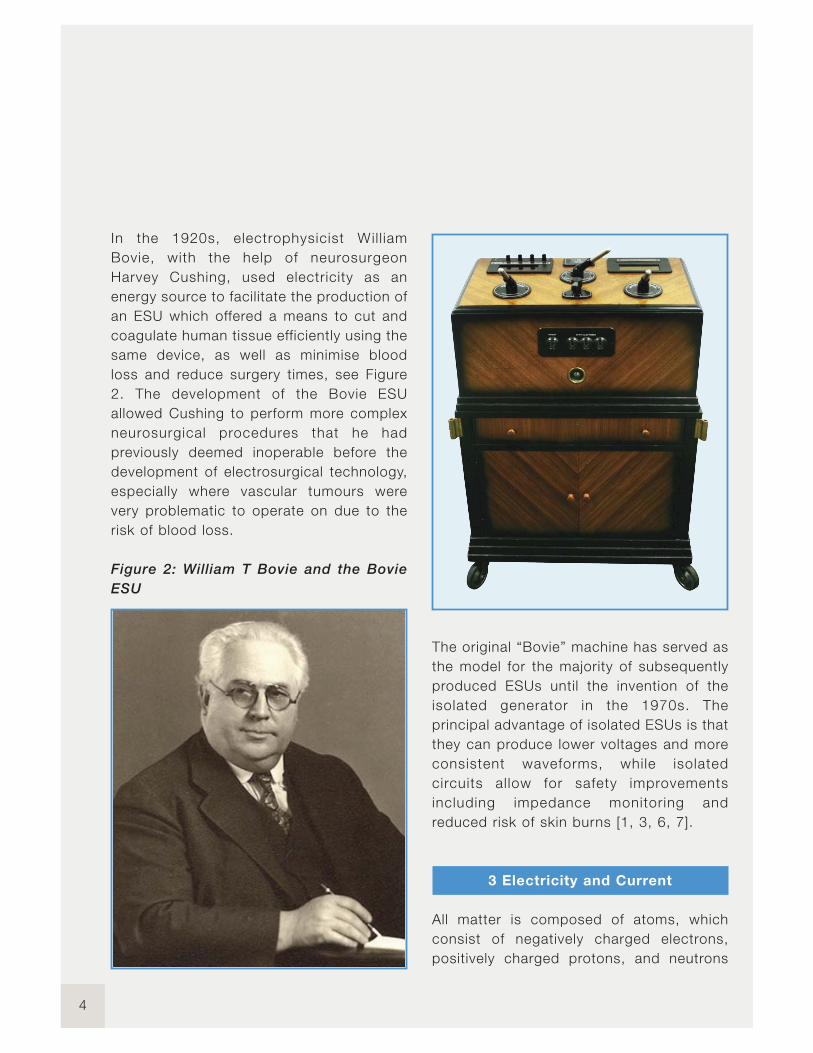
In the 1920s, electrophysicist Wil l iam
Bovie, with the help of neurosurgeon
Harvey Cushing, used electricity as an
energy source to facilitate the production of
an ESU which offered a means to cut and
coagulate human tissue efficiently using the
same device, as well as minimise blood
loss and reduce surgery times, see Figure
2. The development of the Bovie ESU
allowed Cushing to perform more complex
neurosurgical procedures that he had
previously deemed inoperable before the
development of electrosurgical technology,
especially where vascular tumours were
very problematic to operate on due to the
risk of blood loss.
Figure 2: William T Bovie and the Bovie
ESU
The original “Bovie” machine has served as
the model for the majority of subsequently
produced ESUs until the invention of the
isolated generator in the 1970s. The
principal advantage of isolated ESUs is that
they can produce lower voltages and more
consistent waveforms, while isolated
circuits al low for safety improvements
including impedance monitoring and
reduced risk of skin burns [1, 3, 6, 7].
3 Electricity and Current
All matter is composed of atoms, which
consist of negatively charged electrons,
positively charged protons, and neutrons
4

5
www.rigelmedical.com
which have a neutral polarity. Atoms are
neutrally charged when equal numbers of
electrons and protons are present.
Electrons orbit atoms and with energy
move out from one atom to another. The
net charge of the atom changes due to this
movement; atoms with more protons than
electrons become positively charged, and
atoms with more electrons become
negatively charged. Two properties of
electricity that can influence patient care
during surgery are that electricity
will always follow the pathway of least
resistance; and that it will always seek to
return to an electron reservoir like ground
[1, 2, 8].
Electrical current is the movement of
electrons due to a force which is driven by
a difference in voltage. Electrical current is
directly proportional to the voltage in
relation to the electrical resistance in the
circuit, as defined by the equation:
Current (I) = Voltage (V) / Resistance (R)
Two types of current exist; direct (DC) and
alternating current (AC). Direct current
allows electrons to flow from the negative
terminal through the circuit to the positive
terminal in one direction (polarity) such as a
simple battery. Alternating current, such as
the current from an electrical wall outlet,
constantly changes polarity. Frequency is
used to define the number of times an AC
changes polarity per second, measured in
cycles per second or hertz (Hz). AC current
is used to power most electrical devices
within operating rooms [1, 2].
In electrosurgery, the patient is a
fundamental part of the electrical circuit as
the current must flow through the body,
which acts as a conductor. Early studies
into electricity with the body by d’Arsonval
discovered that electricity can cause body
temperature to increase. Current density is
the current applied per unit area. Heat
production is a function of the current
density, resistance and time. The heat
generated is inversely proportional to the
surface area of the electrode which means
the smaller the electrode, the more
localised and intense the heat energy
produced will be, and a higher current
density results in a higher concentration of
heat production [1, 2].
4 Electrosurgery
Electrosurgery is based on the
transformation of an energy current into
heat, with the resulting effect of cutting and
coagulating tissue at the point of current
application. Electrosurgery uses high
voltage and high frequency AC current and
the electrosurgical circuit is composed of
an electrical generator or ESU, an active
electrode, the patient and a return
electrode. Current enters the body because
it is included in the circuit and biological
tissue provides impedance which results in
heat production as the electrons try to
overcome this resistance [1].
Innova t ing Togethe r

Figure 3: AC current frequency
Standard mains operate at a frequency of
50 or 60 Hz throughout most of the world.
However; at this relatively low frequency,
current can be felt by the body with
possible complications including acute
pain, muscle spasms, cardiac arrests or
heart arrhythmias that could result from
excessive neuromuscular stimulation due to
the current and even a high risk of
electrocution, see Figure 3. Therefore for
patient safety and because muscle and
nerve stimulation cease above frequencies
of 100 KHz, radio frequencies are utilised,
where radio refers to the region of
the electromagnetic spectrum where
electromagnetic waves can be generated
by AC currents, see Figure 3. The use of
high frequencies is crucial as frequencies
above 200 KHz do not affect susceptible
tissue therefore eliminating the possibility of
neuromuscular and cardiac interference
with the patient during surgery. The ESU’s
generator is used to convert the mains
electricity supply at a frequency of 50 or 60
Hz to high radio frequency waveforms and
creates a voltage for the flow of current
which allows the electrosurgical energy to
pass safely through the patient [1-3, 6, 8].
5 Techniques of Delivery
5.1 Monopolar
Monopolar electrosurgery is the most
commonly used mode in surgery and is
usually represented by the Bovie pencil
(small single probe), which is an active
electrode located at the surgical site. The
electrical current flows from the active
electrode through the patient’s body, to the
patient return electrode and back to the
generator, see Figure 4. The return
electrode which is located on the patient's
body away from the surgical site, has a
large surface area and low impedance used
to disperse the electrical current back to
the generator, which is necessary to
complete the circuit and prevent alternate
burn sites as the high frequency AC current
leaves the patient’s body. A high current
density is produced at the tip of the probe
which results in thermal heating and
localised destruction. Monopolar
techniques are used for cutting, fulguration
and dessication. Cutting and fulguration
require sparking and high voltages whereas
desiccation needs a large current flow
through the patient [1, 3, 5, 9, 10].
6
7
www.rigelmedical.com
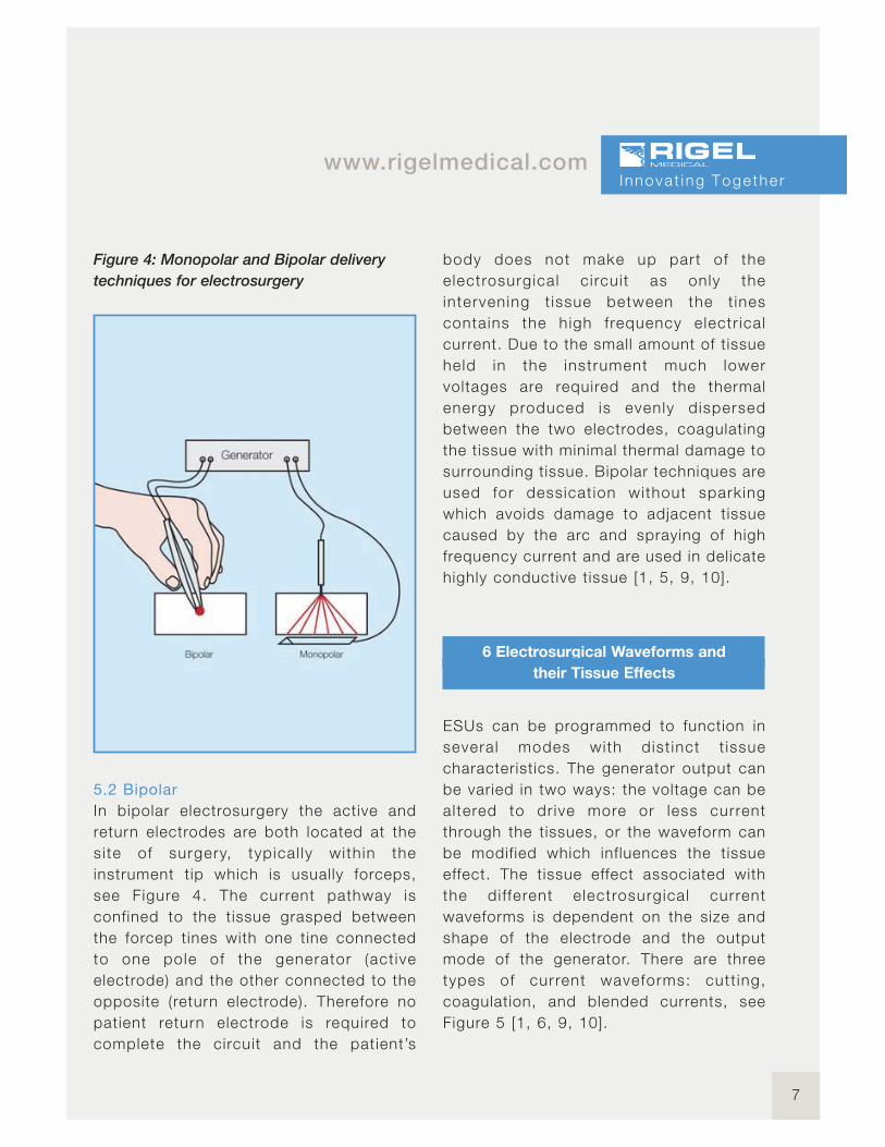
Figure 4: Monopolar and Bipolar delivery
techniques for electrosurgery
5.2 Bipolar
In bipolar electrosurgery the active and
return electrodes are both located at the
si te of surgery, typical ly with in the
instrument tip which is usually forceps,
see Figure 4. The current pathway is
confined to the tissue grasped between
the forcep tines with one tine connected
to one pole of the generator (act ive
electrode) and the other connected to the
opposite (return electrode). Therefore no
patient return electrode is required to
complete the circuit and the patient’s
body does not make up part of the
electrosurgical c i rcui t as only the
intervening t issue between the t ines
contains the high frequency electr ical
current. Due to the small amount of tissue
held in the instrument much lower
voltages are required and the thermal
energy produced is evenly dispersed
between the two electrodes, coagulating
the tissue with minimal thermal damage to
surrounding tissue. Bipolar techniques are
used for dessicat ion without sparking
which avoids damage to adjacent tissue
caused by the arc and spraying of high
frequency current and are used in delicate
highly conductive tissue [1, 5, 9, 10].
6 Electrosurgical Waveforms and
their Tissue Effects
ESUs can be programmed to function in
several modes with dist inct t issue
characteristics. The generator output can
be varied in two ways: the voltage can be
altered to dr ive more or less current
through the tissues, or the waveform can
be modified which influences the tissue
effect. The tissue effect associated with
the di fferent e lectrosurgical current
waveforms is dependent on the size and
shape of the electrode and the output
mode of the generator. There are three
types of current waveforms: cutt ing,
coagulation, and blended currents, see
Figure 5 [1, 6, 9, 10].
Innova t ing Togethe r
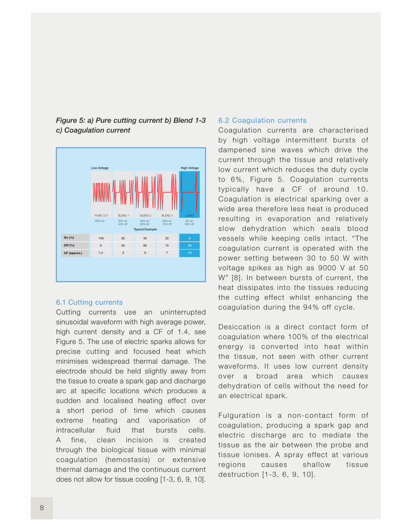
Figure 5: a) Pure cutting current b) Blend 1-3
c) Coagulation current
6.1 Cutting currents
Cutting currents use an uninterrupted
sinusoidal waveform with high average power,
high current density and a CF of 1.4, see
Figure 5. The use of electric sparks allows for
precise cutting and focused heat which
minimises widespread thermal damage. The
electrode should be held slightly away from
the tissue to create a spark gap and discharge
arc at specific locations which produces a
sudden and localised heating effect over
a short period of time which causes
extreme heating and vaporisation of
intracellular fluid that bursts cells.
A f ine, clean incision is created
through the biological tissue with minimal
coagulation (hemostasis) or extensive
thermal damage and the continuous current
does not allow for tissue cooling [1-3, 6, 9, 10].
6.2 Coagulation currents
Coagulation currents are characterised
by high voltage intermittent bursts of
dampened sine waves which drive the
current through the t issue and relat ively
low current which reduces the duty cycle
to 6%, Figure 5. Coagulat ion currents
typ ica l ly have a CF of around 10.
Coagulat ion is electr ical sparking over a
wide area therefore less heat is produced
result ing in evaporat ion and relat ively
s low dehydrat ion which sea ls b lood
vessels whi le keeping cel ls intact. “The
coagulat ion current is operated with the
power sett ing between 30 to 50 W with
voltage spikes as high as 9000 V at 50
W” [8]. In between bursts of current, the
heat dissipates into the t issues reducing
the cutt ing effect whi lst enhancing the
coagulat ion during the 94% off cycle.
Desiccation is a direct contact form of
coagulat ion where 100% of the electr ical
energy is converted into heat wi th in
the t issue, not seen with other current
waveforms. It uses low current density
over a broad area which causes
dehydration of cel ls without the need for
an electr ical spark.
Fulgurat ion is a non-contact form of
coagulat ion, producing a spark gap and
electr ic discharge arc to mediate the
tissue as the air between the probe and
tissue ionises. A spray effect at various
reg ions causes sha l low t issue
destruction [1-3, 6, 9, 10].
8
High VoltageLow Voltage
COAGBLEND 3BLEND 2BLEND 1PURE CUT
Typical Example
94% off
6% on
75% off
25% on
60% off
40% on
50% off
50% on100% on
9
www.rigelmedical.com
6.3 Blended currents
A blended current is a modification of the
duty cycle and operates at voltages
between those of cutting and coagulation
with a CF usually in the range of 3 to 10.
Blended currents allow for tissue division
whilst maintaining a variable degree of
hemostasis which is defined by the off
period. Although the total energy remains
the same, the ratio of voltage and current is
adjusted to increase hemostasis; by
interrupting the current and increasing the
voltage, to deliver a waveform in
intermittent bursts. Three blends are shown
in Figure 5. Modifications and reductions to
the duty cycle through progressive blends
produce less heat and as the interval
between bursts progressively increases,
greater coagulation is produced. However,
as homeostasis increases, the cutting
ability of the blended current decreases
[1-3, 6, 9, 10].
The rate at which heat is produced is the
dominant factor and only variable in
determining whether a waveform vaporises
or coagulates biological tissue. Surgeons
have the option to combine the cut and
coagulate currents to produce different
tissue effects. Coagulation can be
performed with the cutting current by using
the electrode in direct contact with the
tissue and this requires less voltage than
the coagulation waveform. However power
settings may need to be adjusted and
electrode size varied to achieve the desired
surgical effect [1].
7 Electrosurgical Units (ESUs)
7.1 Ground referenced generators
Originally, ESUs were ground referenced
where the electrical current passed through
the patient’s body and returned to ground.
The grounding is intended to occur via the
patient return electrode which is usually
situated on the thigh of the patient and
away from the surgical site. However,
electrical currents seek to travel down the
pathway of least resistance and therefore
current can travel through any conductive
grounding object which is in contact with
the patient as a method of ground return;
such as ECG electrodes or tables and
operating staff. This increases the
possibility of creating alternate site burns
on the patient at alternative grounding sites
where the high frequency current has exited
the patient. Many manufacturers no longer
rely on ground referenced ESUs due to the
high risk of skin burns associated with
alternative grounding [1, 8, 9].
7.2 Isolated generators
Isolated generator systems were developed
in the early 1970's to overcome the risk of
alternative site burns due to grounded
systems. The current still passes through
the patient and must return through the
patient return electrode which leads to the
negative side of an isolation transformer
located within the generator. The return
electrode is not connected or referenced
to ground and therefore a l ternate
pathways are avoided. The transformer
Innova t ing Togethe r
isolates the power with no voltage reference
to ground so that the current does not return
to ground or seek other grounded objects,
therefore eliminating alternate skin burns.
If the current does not find its way to the
patient return electrode then the ESU will stop
delivering energy current as there must be an
alternative grounding path of less resistance
than the return electrode [1, 8, 9].
7.3 Active electrode
The active electrode delivers the high
frequency AC current from the ESU to the
surgical site. At the tip of the active electrode,
electron flow and current density are high and
spread across a relatively small area. The
current density varies depending on the type,
size and shape of the tip. There are a variety
of tips available including bipolar forceps for
desiccation, needle electrodes for precise cut
and coagulation, blade electrodes for faster
cut and coagulation and ball tips for broad
coagulation. The monopolar active electrode
is typically a small flat blade with the edges
shaped to easily initiate discharge arcs.
Needle tip electrodes require a lower power
setting than blade or ball electrodes because
the current is concentrated on a very small
area at the tip of the electrode, see Figure 6.
The active electrode should be used in an
insulated holster which will prevent accidental
burns to the patient and surgeon. To control
the waveform, footswitches or switches on
the active electrode handle allow the surgeon
to alternate between cutting and coagulation
currents [5, 8].
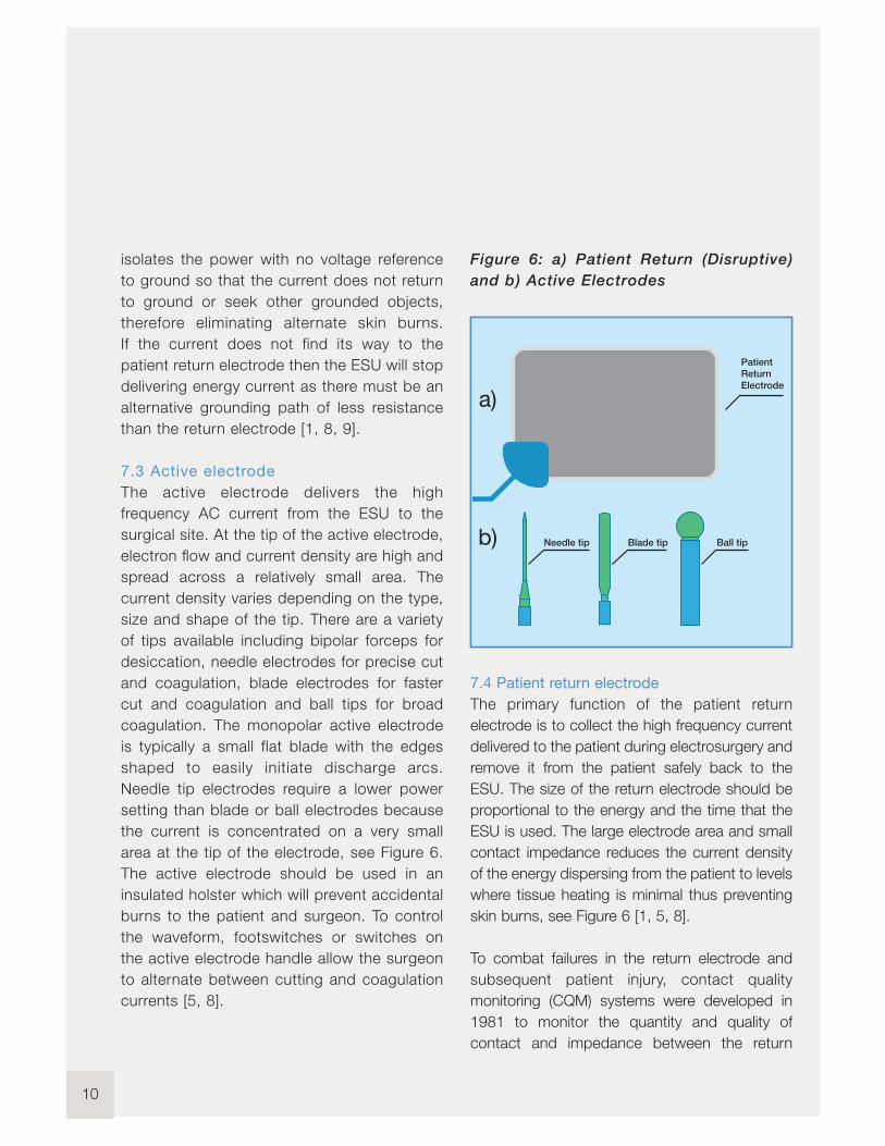
Figure 6: a) Patient Return (Disruptive)
and b) Active Electrodes
7.4 Patient return electrode
The primary function of the patient return
electrode is to collect the high frequency current
delivered to the patient during electrosurgery and
remove it from the patient safely back to the
ESU. The size of the return electrode should be
proportional to the energy and the time that the
ESU is used. The large electrode area and small
contact impedance reduces the current density
of the energy dispersing from the patient to levels
where tissue heating is minimal thus preventing
skin burns, see Figure 6 [1, 5, 8].
To combat failures in the return electrode and
subsequent patient injury, contact quality
monitoring (CQM) systems were developed in
1981 to monitor the quantity and quality of
contact and impedance between the return
10
Patient
Return
Electrode
Ball tipBlade tipNeedle tip
a)
b)
11
www.rigelmedical.com
electrode and the patient. The CQM system is a
separate monitoring current which is sent to the
patient return electrode and measures the
patient impedance. If the contact is interrupted,
or there is a failure, an alarm sounds and the ESU
is deactivated to prevent further damage; the
CQM system only allows the ESU generator to
function between a preselected safe range and
detects increases in impedance at the return
electrode to prevent potential injury and skin
burns at the return electrode [1, 3, 6-10].
8 ESU Hazards and Complications
An electric current needs a closed circuit for
electricity to flow and therefore current has the
potential to travel along alternative pathways of
less resistance which can cause undesired
effects. Improper electrosurgery can expose
both the patient and staff to potential hazards
such as electric shock and skin burns [6, 8, 9].
ESUs can cause burns at the intended surgical
site, at alternate sites and at the return electrode.
The patient return electrode is a common site of
injury; which can be caused due to insufficient
size to safely disperse current, or interrupted and
significantly reduced contact with the patient,
which can result in the current exiting the body
and producing unintended burns. Current can
divert through an alternative earthing point and
cause accidental burning elsewhere on the body.
To avoid this, the patient should not touch any
metal object and is usually placed on an
insulated mattress to isolate the patient [9, 10].
Surgical smoke is produced as the tissue is
heated and vaporised and some of this smoke
contains potentially harmful chemicals such as
carcinogens and cellular debris. To minimise the
associated health hazards, specially designed
smoke evacuation systems are used and
filtration masks worn during surgery [2, 8, 10].
ESUs are the most common source of ignition in
operating room fires and explosions. Alcohol-
based skin preparation should be avoided
because liquids can pool under surgical towels
and be ignited by sparks from the active
electrode. Electrosurgery sparks can also ignite
flammable gases within body cavities [6, 10].
9 Testing Electrosurgical Generators
Electrosurgery is the principle of inducing heat by
high frequency electrical current for coagulation,
cutting, desiccation and fulguration of biological
tissue developed by Bovie. The correct operation
of electrosurgical generators is essential to
ensure patient safety and manage the risks
associated with the use of high and low
frequency electrical current on the human body.
Manufacturers of electrosurgical generators must
follow the strict design criteria of IEC 60601-2-2,
which stipulates the specific requirements in
order to provide a controlled approach to patient
safety when using electrosurgical devices.
A thorough understanding of each energy
modality, waveform and tissue effect is critical in
reducing potential complications and hazards
whilst the performance and safety of these
Innova t ing Togethe r

electrosurgical devices must be regularly verified
(every 3-6 months) for instance by using the Rigel
Uni-Therm electrosurgical analyser, see Figure 7 [2, 9].
A typical test procedure to ensure the electrical
safety and performance is assessed can consist
of the following test steps:
1) Visual inspection
2) Low frequency electrical safety test
(leakage currents up to 1kHz), see Rigel
Medical’s IEC 62353 guidance booklet
3) Verification of the contact quality
monitoring (CQM) circuit, see 9.1
4) Testing for high frequency leakage, see 9.2
5) Check output power at certain loads
in relation to the function and waveform
selection, see 9.3
Be aware; when testing electrosurgical generators,
it is crucial to understand the operation of the
device under test (DUT). The output energy of
electrosurgical generators can lead to burn injuries.
Always ensure that the tests are conducted by a
suitably trained individual and limit the amount of
accessible conductive parts that become live with
high frequency electrical current.
To maximise safety, Rigel Medical has developed a
number of accessories to automate the testing and
reduce the need for manual interaction during
testing and whilst the output of electrical surgical
generators are active. See 9.4.
The new Uni-Therm electrosurgical analyser from
Rigel Medical is the quickest and easiest way to test
all leading electrosurgical generators, combining the
test functions to verify the CQM, the high frequency
leakage and the output power, all in a single test
device. By providing built-in automation and data
storage, the Rigel Uni-Therm can be utilised both in
the field as well as at the end of demanding
production lines or in test laboratories.
Figure 7: Rigel Medical’s Uni-Therm
9.1 Contact quality monitoring
(CQM) verification
To maximise the effectiveness of the surgical
procedure and to reduce the risk of injury during
electrosurgical procedures, the patient plate must
cover an optimum amount of skin surface area
(quantity) and be high in conductivity (quality) where
the energy exits the patient. This is monitored by the
electrosurgical device through impedance
12

13
www.rigelmedical.com
measurement (CQM) between the two (split) or more
conductive pads within the patient return plate, see
Figure 8. When extreme variations or very high/low
impedance appears, the CQM will lead to an audible
and/or visual alarm and can lead to deactivation of
the output energy to prevent potential patient injury.
Figure 8: Example of patient return plate
The Uni-Therm’s accurate CQM function
simulator allows automatic and manual increase
or decrease of electrical resistance values in 1Ωresolution. This enables the testing of modern
contact quality monitoring systems that are
triggered by relative changes in resistance.
To carry out the CQM test using the Rigel
Uni-Therm, connect a CQM test lead between
the patient plate connector and the front panel of
the Rigel Uni-Therm, see Figure 9.
Figure 9: Connecting Rigel Uni-Therm to the
CQM circuit
Unlike conventional analysers, the Rigel
Uni-Therm utilises a motor driven potentiometer
which can simulate resistance variations to within 1Ωresolution. This allows the user to trigger the CQM
system by simulating fault conditions including very
high or very low impedance values or a large variation
in impedance, for example a change of 10%.
The variable resistance (0–475Ω) is connected to
two black connectors on the CQM section at the
front of the Uni-Therm, and also connects to the
neutral plate connector on the ESU. Impedance can
be controlled by utilising the rotary encoder on the
front panel to increase or decrease the impedance,
see Figure 10 and 11.
Figure 10: Rotary encoder on the Rigel Uni-Therm
I nnova t ing Togethe r

Figure 11: CQM test screen on Rigel Uni-Therm
9.2 High frequency leakage test
Design criteria of electrosurgical generators (IEC
60601-2-2), require the manufacture to limit the
amount of capacitive leakage of the high frequency
current. At frequencies exceeding 400kHz, the
electrical current has a tendency to stray, leading to
decrease in functionality and possible injury to the
patient.
Capacitive coupling might occur between the test
leads during the setup. This is the reason why IEC
60601-2-2 stipulates specific layout of test leads
and test loads to ensure the capacitive coupling is
limited and controlled in a laboratory environment,
these tests are referred to as the long lead tests. A
more practical approach is to ensure the test leads
are as short as possible and do not cross over, to
limit the influence of capacitive coupling.
Breakdown of insulation in the surgery leads as a
result of high voltages (peak to peak up to 10kV) is
also a consideration when testing the electrosurgical
generator. This can be verified by including the
surgical leads as part of the test setup. Beware that
this might lead to exposure to conductive parts and
possible injury.
The HF leakage test measures the HF leakage
current in various test configurations and compares
the result to a user set pass/fail value using the rotary
encoder to navigate the screens.
The Uni-Therm simplifies the complex test
configurations of high frequency leakage current
measurement, as required by IEC 60601-2-2, by
providing detailed instructional diagrams for each
high frequency leakage test set-up on its colour
display, see Figure 12.
Figure 12: Test screens for HF leakage on the
Rigel Uni-Therm
14

15
www.rigelmedical.com
Each high frequency leakage measurement can
be automatically initiated through the cut and
coag control on the Uni-Therm, improving safety
and speed of testing, see Figure 13.
Figure 13: Connection panel on the Rigel
Uni-Therm
9.3 Power management
The Uni-Therm provides a variety of options
during the power measurement and has the
ability to measure currents of up to 8 Ampere
RMS. The unique internal load bank is designed
to minimise the phase shift, which can lead to
inaccurate measurements at high frequencies
and is typical of traditional electrosurgical
analysers, see Figure 14.
Figure 14, Connecting the ESU power to the
Rigel Uni-Therm.
Current measurement in the Rigel Uni-Therm is
done through the use of a custom designed
current transformer, capable of accurately
measuring high currents when calibrating
electrosurgical generators with high current
vessel sealing treatment functions.
The power measurement options include:
n Continuous: Measuring output power and
current during a single load value
n Graph: Measuring the output power and
current under a changing load condition
n External load: Measuring the output and
current during short circuit testing or when
using a specific external load resistor during
development.
The large colour display provides a clear and
detailed interpretation of output power whilst cut
and coag foot paddle control automates the
process; making this a fast, effective and safe
test procedure.
Innova t ing Togethe r
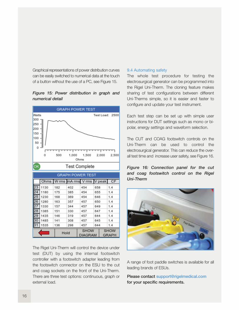
Graphical representations of power distribution curves
can be easily switched to numerical data at the touch
of a button without the use of a PC, see Figure 15.
Figure 15: Power distribution in graph and
numerical detail
The Rigel Uni-Therm will control the device under
test (DUT) by using the internal footswitch
controller with a footswitch adapter leading from
the footswitch connector on the ESU to the cut
and coag sockets on the front of the Uni-Therm.
There are three test options: continuous, graph or
external load.
9.4 Automating safety
The whole test procedure for testing the
electrosurgical generator can be programmed into
the Rigel Uni-Therm. The cloning feature makes
sharing of test configurations between different
Uni-Therms simple, so it is easier and faster to
configure and update your test instrument.
Each test step can be set up with simple user
instructions for DUT settings such as mono or bi-
polar, energy settings and waveform selection.
The CUT and COAG footswitch controls on the
Uni-Therm can be used to control the
electrosurgical generator. This can reduce the over-
all test time and increase user safety, see Figure 16.
Figure 16: Connection panel for the cut
and coag footswitch control on the Rigel
Uni-Therm
A range of foot paddle switches is available for all
leading brands of ESUs.
Please contact [email protected]
for your specific requirements.
16

17
www.rigelmedical.com
10 Conclusion
The use of electrosurgical generators has
led to more effective surgical treatments
and improved pat ient safety through
greater contro l and management of
complications during surgery.
Never the less, the use of electrosurgical
generators is not wi thout r isk and
remains one of the more hazardous
practises in operating theatres.
Regular performance and safety tests of
these high frequency generators can lead
to further improvement of patient safety
by ensuring the safety features of each
generator is in- tact , and that the
performance accuracy is guaranteed.
When cons ider ing the purchase of
e lectrosurg ica l ana lysers, ensure that
you understand the manufacturer ’s
requirements and the technical capabi l i ty
of your instal l base. For instance, when
cal ibrat ing e lect rosurg ica l generators
wi th h igh current vesse l sea l ing
technology, look for test equipment that
can measure both short circuit currents
as wel l as currents over 5A RMS.
The Rigel Uni-Therm is versat i le and
compact yet offers safer, faster and more
accurate test ing of e lect rosurg ica l
generators enabl ing you to meet
international and manufacturer specif ic
test requirements simply and eff iciently.
We hope you have found the information
in this booklet useful and interesting,
we welcome your feedback.
Please direct your feedback and
questions to:
You can also fol low us on:
Innova t ing Togethe r
18
References
1. Jones, C. M., Pierre, K. B., Nicoud, I. B., Stain, S. C. (2006). Electrosurgery. Current Surgery.
63 (6) 458-463.
2. Gallagher, K., Dhinsa, B., Miles, J. (2010). Electrosurgery. Surgery. 29 (2) 70-72. (2007).
3. Electrosurgery Available: www.boss.net.au/clinical/studynotes/genper01.htm.
Last accessed 18th Feb 2013.
4. Bussiere, R. L. (1997). Principles of Electrosurgery. Washington, U.S.A: Edmonds. 6.
5. Eggleston, J. L., Von Maltzahn, W.W. (2000). Electrosurgical Devices. In: Ed. Joseph D. Bronzino.
The Biomedical Engineering Handbook. Boca Raton: CRC Press LLC.
6. Davison, J. M., Zamah, N. M. (2008). Electrosurgery: Principles, Biologic Effects and Results in
Female Reproductive Surgery. Available:
www.glowm.com/index.html?p=glowm.cml/section_view&articleid=21.
Last accessed 18th Feb 2013.
7. Massarweh, N. N., Cosgriff, N., Slakey, D. P. (2006). Electrosurgery: History, Principles,
and Current and Future Uses. Electrosurgery. 202 (3) 520-530.
8. Megadyne. The Electrical Authority (2005). Principles of Electrosurgery. Utah
9. K. Wang, A.P. Advincula. (2007). Current thoughts in Electrosurgery: Surgery and Technology.
International Journal of Gynaecology and Obstetrics. 97, 245-250.
10.Hay, D.J. (2005). Electrosurgery. Surgery. 23 (29) 73-75.

19
www.rigelmedical.comI nnova t ing Togethe r
Photo Credit
Page 4: Bovie ESU
Bovie Medical Corporation
5115 Ulmerton Road, Clearwater, Florida, 33760 USA
T: +1 727 - 803 - 8558 F: +1 727 - 347 -9144
20
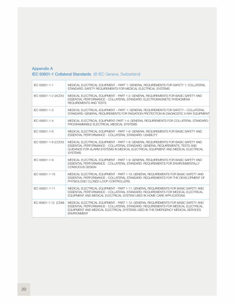
Appendix A
IEC 60601-1 Collateral Standards (© IEC Geneva, Switzerland)
IEC 60601-1-1
IEC 60601-1-2 (ACDV)
IEC 60601-1-3
IEC 60601-1-4
IEC 60601-1-6
IEC 60601-1-8 (CCDV)
IEC 60601-1-9
IEC 60601-1-10
IEC 60601-1-11
IEC 60601-1-12 (CDM)
MEDICAL ELECTRICAL EQUIPMENT – PART 1: GENERAL REQUIREMENTS FOR SAFETY 1: COLLATERALSTANDARD: SAFETY REQUIREMENTS FOR MEDICAL ELECTRICAL SYSTEMS
MEDICAL ELECTRICAL EQUIPMENT - PART 1-2: GENERAL REQUIREMENTS FOR BASIC SAFETY ANDESSENTIAL PERFORMANCE - COLLATERAL STANDARD: ELECTROMAGNETIC PHENOMENA -REQUIREMENTS AND TESTS
MEDICAL ELECTRICAL EQUIPMENT – PART 1: GENERAL REQUIREMENTS FOR SAFETY – COLLATERALSTANDARD: GENERAL REQUIREMENTS FOR RADIATION PROTECTION IN DIAGNOSTIC X-RAY EQUIPMENT
MEDICAL ELECTRICAL EQUIPMENT: PART 1-4: GENERAL REQUIREMENTS FOR COLLATERAL STANDARD:PROGRAMMABLE ELECTRICAL MEDICAL SYSTEMS
MEDICAL ELECTRICAL EQUIPMENT - PART 1-6: GENERAL REQUIREMENTS FOR BASIC SAFETY ANDESSENTIAL PERFORMANCE - COLLATERAL STANDARD: USABILITY
MEDICAL ELECTRICAL EQUIPMENT - PART 1-8: GENERAL REQUIREMENTS FOR BASIC SAFETY ANDESSENTIAL PERFORMANCE - COLLATERAL STANDARD: GENERAL REQUIREMENTS, TESTS ANDGUIDANCE FOR ALARM SYSTEMS IN MEDICAL ELECTRICAL EQUIPMENT AND MEDICAL ELECTRICALSYSTEMS
MEDICAL ELECTRICAL EQUIPMENT - PART 1-9: GENERAL REQUIREMENTS FOR BASIC SAFETY ANDESSENTIAL PERFORMANCE - COLLATERAL STANDARD: REQUIREMENTS FOR ENVIRONMENTALLYCONSCIOUS DESIGN
MEDICAL ELECTRICAL EQUIPMENT - PART 1-10: GENERAL REQUIREMENTS FOR BASIC SAFETY ANDESSENTIAL PERFORMANCE - COLLATERAL STANDARD: REQUIREMENTS FOR THE DEVELOPMENT OFPHYSIOLOGIC CLOSED-LOOP CONTROLLERS
MEDICAL ELECTRICAL EQUIPMENT - PART 1-11: GENERAL REQUIREMENTS FOR BASIC SAFETY ANDESSENTIAL PERFORMANCE - COLLATERAL STANDARD: REQUIREMENTS FOR MEDICAL ELECTRICALEQUIPMENT AND MEDICAL ELECTRICAL SYSTEM USED IN HOME CARE APPLICATIONS
MEDICAL ELECTRICAL EQUIPMENT - PART 1-12: GENERAL REQUIREMENTS FOR BASIC SAFETY ANDESSENTIAL PERFORMANCE - COLLATERAL STANDARD: REQUIREMENTS FOR MEDICAL ELECTRICALEQUIPMENT AND MEDICAL ELECTRICAL SYSTEMS USED IN THE EMERGENCY MEDICAL SERVICESENVIRONMENT
21
www.rigelmedical.comI nnova t ing Togethe r
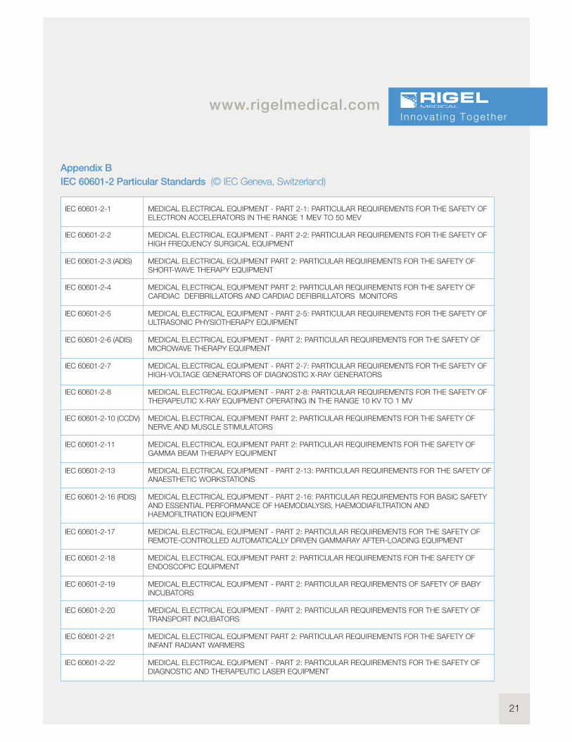
Appendix B
IEC 60601-2 Particular Standards (© IEC Geneva, Switzerland)
IEC 60601-2-1
IEC 60601-2-2
IEC 60601-2-3 (ADIS)
IEC 60601-2-4
IEC 60601-2-5
IEC 60601-2-6 (ADIS)
IEC 60601-2-7
IEC 60601-2-8
IEC 60601-2-10 (CCDV)
IEC 60601-2-11
IEC 60601-2-13
IEC 60601-2-16 (RDIS)
IEC 60601-2-17
IEC 60601-2-18
IEC 60601-2-19
IEC 60601-2-20
IEC 60601-2-21
IEC 60601-2-22
MEDICAL ELECTRICAL EQUIPMENT - PART 2-1: PARTICULAR REQUIREMENTS FOR THE SAFETY OFELECTRON ACCELERATORS IN THE RANGE 1 MEV TO 50 MEV
MEDICAL ELECTRICAL EQUIPMENT - PART 2-2: PARTICULAR REQUIREMENTS FOR THE SAFETY OFHIGH FREQUENCY SURGICAL EQUIPMENT
MEDICAL ELECTRICAL EQUIPMENT PART 2: PARTICULAR REQUIREMENTS FOR THE SAFETY OFSHORT-WAVE THERAPY EQUIPMENT
MEDICAL ELECTRICAL EQUIPMENT PART 2: PARTICULAR REQUIREMENTS FOR THE SAFETY OFCARDIAC DEFIBRILLATORS AND CARDIAC DEFIBRILLATORS MONITORS
MEDICAL ELECTRICAL EQUIPMENT - PART 2-5: PARTICULAR REQUIREMENTS FOR THE SAFETY OFULTRASONIC PHYSIOTHERAPY EQUIPMENT
MEDICAL ELECTRICAL EQUIPMENT - PART 2: PARTICULAR REQUIREMENTS FOR THE SAFETY OFMICROWAVE THERAPY EQUIPMENT
MEDICAL ELECTRICAL EQUIPMENT - PART 2-7: PARTICULAR REQUIREMENTS FOR THE SAFETY OFHIGH-VOLTAGE GENERATORS OF DIAGNOSTIC X-RAY GENERATORS
MEDICAL ELECTRICAL EQUIPMENT - PART 2-8: PARTICULAR REQUIREMENTS FOR THE SAFETY OFTHERAPEUTIC X-RAY EQUIPMENT OPERATING IN THE RANGE 10 KV TO 1 MV
MEDICAL ELECTRICAL EQUIPMENT PART 2: PARTICULAR REQUIREMENTS FOR THE SAFETY OFNERVE AND MUSCLE STIMULATORS
MEDICAL ELECTRICAL EQUIPMENT PART 2: PARTICULAR REQUIREMENTS FOR THE SAFETY OFGAMMA BEAM THERAPY EQUIPMENT
MEDICAL ELECTRICAL EQUIPMENT - PART 2-13: PARTICULAR REQUIREMENTS FOR THE SAFETY OFANAESTHETIC WORKSTATIONS
MEDICAL ELECTRICAL EQUIPMENT - PART 2-16: PARTICULAR REQUIREMENTS FOR BASIC SAFETYAND ESSENTIAL PERFORMANCE OF HAEMODIALYSIS, HAEMODIAFILTRATION ANDHAEMOFILTRATION EQUIPMENT
MEDICAL ELECTRICAL EQUIPMENT - PART 2: PARTICULAR REQUIREMENTS FOR THE SAFETY OFREMOTE-CONTROLLED AUTOMATICALLY DRIVEN GAMMARAY AFTER-LOADING EQUIPMENT
MEDICAL ELECTRICAL EQUIPMENT PART 2: PARTICULAR REQUIREMENTS FOR THE SAFETY OFENDOSCOPIC EQUIPMENT
MEDICAL ELECTRICAL EQUIPMENT - PART 2: PARTICULAR REQUIREMENTS OF SAFETY OF BABYINCUBATORS
MEDICAL ELECTRICAL EQUIPMENT - PART 2: PARTICULAR REQUIREMENTS FOR THE SAFETY OFTRANSPORT INCUBATORS
MEDICAL ELECTRICAL EQUIPMENT PART 2: PARTICULAR REQUIREMENTS FOR THE SAFETY OFINFANT RADIANT WARMERS
MEDICAL ELECTRICAL EQUIPMENT - PART 2: PARTICULAR REQUIREMENTS FOR THE SAFETY OFDIAGNOSTIC AND THERAPEUTIC LASER EQUIPMENT

22
IEC 60601-2-23
IEC 60601-2-24 (ADIS)
IEC 60601-2-25
IEC 60601-2-26 (ADIS)
IEC 60601-2-27
IEC 60601-2-28
IEC 60601-2-29
IEC 60601-2-31
IEC 60601-2-32
IEC 60601-2-33
IEC 60601-2-34
IEC 60601-2-36 (1CD)
IEC 60601-2-37
IEC 60601-2-39
IEC 60601-2-40
IEC 60601-2-41 (CCDV)
IEC 60601-2-43
IEC 60601-2-44 (CCDV
MEDICAL ELECTRICAL EQUIPMENT - PART 2-23: PARTICULAR REQUIREMENTS FOR THE SAFETY,INCLUDING ESSENTIAL PERFORMANCE, OF TRANSCUTANEOUSPARTIAL PRESSURE MONITORINGEQUIPMENT
MEDICAL ELECTRICAL EQUIPMENT - PART 2-24: PARITCULAR REQUIREMENTS FOR THE SAFETY OFINFUSION PUMPS AND CONTROLLERS
MEDICAL ELECTRICAL EQUIPMENT - PART 2-25: PARTICULAR REQUIREMENTS FOR THE SAFETY OFELECTROCARDIOGRAPHS
MEDICAL ELECTRICAL EQUIPMENT PART 2: PARTICULAR REQUIREMENTS FOR THE SAFETY OFELECTROENCEPHALOGRAPHS
MEDICAL ELECTRICAL EQUIPMENT - PART 2: PARTICULAR REQUIREMENTS FOR THE SAFETY OFELECTROCARDIOGRAPHIC MONITORING EQUIPMENT
MEDICAL ELECTRICAL EQUIPMENT - PART 2: PARTICULAR REQUIREMENTS FOR THE SAFETY OF X-RAY SOURCE ASSEMBLIES AND X-RAY TUBE ASSEMBLIES FOR MEDICAL DIAGNOSIS
MEDICAL ELECTRICAL EQUIPMENT - PART 2-29: PARTICULAR REQUIREMENTS FOR THE SAFETY OFRADIOTHERAPY SIMULATORS
MEDICAL ELECTRICAL EQUIPMENT - PART 2: PARTICULAR REQUIREMENTS FOR THE SAFETY OFEXTERNAL CARDIAC PACEMAKERS WITH INTERNAL POWER SOURCE
MEDICAL ELECTRICAL EQUIPMENT PART 2: PARTICULAR REQUIREMENTS FOR THE SAFETY OFASSOCIATED EQUIPMENT OF X-RAY EQUIPMENT
MEDICAL ELECTRICAL EQUIPMENT - PART 2: PARTICULAR REQUIREMENTS FOR THE SAFETY OFMAGNETIC RESONANCE EQUIPMENT FOR MEDICAL DIAGNOSIS
MEDICAL ELECTRICAL EQUIPMENT - PART 2: PARTICULAR REQUIREMENTS FOR THE SAFETY,INCLUDING ESSENTIAL PERFORMANCE, OF INVASIVE BLOOD PRESSURE MONITORING EQUIPMENT
MEDICAL ELECTRICAL EQUIPMENT - PART 2: PARTICULAR REQUIREMENTS FOR THE SAFETY OFEQUIPMENT FOR EXTRACORPOREALLY INDUCED LITHOTRIPSY
MEDICAL ELECTRICAL EQUIPMENT - PART 2-37: PARTICULAR REQUIREMENTS FOR THE BASICSAFETY AND ESSENTIAL PERFORMANCE OF ULTRASONIC MEDICAL DIAGNOSTIC AND MONITORINGEQUIPMENT
MEDICAL ELECTRICAL EQUIPMENT - PART 2-39: PARTICULAR REQUIREMENTS FOR THE SAFETY OFPERITONEAL DIALYSIS EQUIPMENT
MEDICAL ELECTRICAL EQUIPMENT - PART 2-40: PARTICULAR REQUIREMENTS FOR THE SAFETY OFELETROMYOGRAPHS AND EVOKED RESPONSE EQUIPMENT
MEDICAL ELECTRICAL EQUIPMENT - PART 2-41: PARTICULAR REQUIREMENTS FOR THE SAFETY OFSURGICAL LUMINAIRES AND LUMINAIRES FOR DIAGNOSIS
MEDICAL ELECTRICAL EQUIPMENT - PART 2-43: PARTICULAR REQUIREMENTS FOR THE SAFETY OFX-RAY EQUIPMENT FOR INTERVENTIONAL PROCEDURES
MEDICAL ELECTRICAL EQUIPMENT - PART 2-44: PARTICULAR REQUIREMENTS FOR THE SAFETY OFX-RAY EQUIPMENT FOR COMPUTED TOMOGRAPHY
23
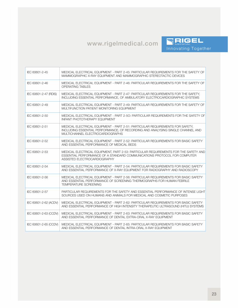
www.rigelmedical.comI nnova t ing Togethe r
IEC 60601-2-45
IEC 60601-2-46
IEC 60601-2-47 (RDIS)
IEC 60601-2-49
IEC 60601-2-50
IEC 60601-2-51
IEC 60601-2-52
IEC 60601-2-53
IEC 60601-2-54
IEC 60601-2-56
IEC 60601-2-57
IEC 60601-2-62 (ACDV)
IEC 60601-2-63 (CCDV)
IEC 60601-2-65 (CCDV)
MEDICAL ELECTRICAL EQUIPMENT - PART 2-45: PARTICULAR REQUIREMENTS FOR THE SAFETY OFMAMMOGRAPHIC X-RAY EQUIPMENT AND MAMMOGRAPHIC STEREOTACTIC DEVICES
MEDICAL ELECTRICAL EQUIPMENT - PART 2-46: PARTICULAR REQUIREMENTS FOR THE SAFETY OFOPERATING TABLES
MEDICAL ELECTRICAL EQUIPMENT - PART 2-47: PARTICULAR REQUIREMENTS FOR THE SAFETY,INCLUDING ESSENTIAL PERFORMANCE, OF AMBULATORY ELECTROCARDIOGRAPHIC SYSTEMS
MEDICAL ELECTRICAL EQUIPMENT - PART 2-49: PARTICULAR REQUIREMENTS FOR THE SAFETY OFMULTIFUNCTION PATIENT MONITORING EQUIPMENT
MEDICAL ELECTRICAL EQUIPMENT - PART 2-5O: PARTICULAR REQUIREMENTS FOR THE SAFETY OFINFANT PHOTOTHERAPY EQUIPMENT
MEDICAL ELECTRICAL EQUIPMENT - PART 2-51: PARTICULAR REQUIREMENTS FOR SAFETY,INCLUDING ESSENTIAL PERFORMANCE, OF RECORDING AND ANALYSING SINGLE CHANNEL ANDMULTICHANNEL ELECTROCARDIOGRAPHS
MEDICAL ELECTRICAL EQUIPMENT - PART 2-52: PARTICULAR REQUIREMENTS FOR BASIC SAFETYAND ESSENTIAL PERFORMANCE OF MEDICAL BEDS
MEDICAL ELECTRICAL EQUIPMENT, PART 2-53: PARTICULAR REQUIREMENTS FOR THE SAFETY ANDESSENTIAL PERFORMANCE OF A STANDARD COMMUNICATIONS PROTOCOL FOR COMPUTERASSISTED ELECTROCARDIOGRAPHY
MEDICAL ELECTRICAL EQUIPMENT - PART 2-54: PARTICULAR REQUIREMENTS FOR BASIC SAFETYAND ESSENTIAL PERFORMANCE OF X-RAY EQUIPMENT FOR RADIOGRAPHY AND RADIOSCOPY
MEDICAL ELECTRICAL EQUIPMENT - PART 2-56: PARTICULAR REQUIREMENTS FOR BASIC SAFETYAND ESSENTIAL PERFORMANCE OF SCREENING THERMOGRAPHS FOR HUMAN FEBRILETEMPERATURE SCREENING
PARTICULAR REQUIREMENTS FOR THE SAFETY AND ESSENTIAL PERFORMANCE OF INTENSE LIGHTSOURCES USED ON HUMANS AND ANIMALS FOR MEDICAL AND COSMETIC PURPOSES
MEDICAL ELECTRICAL EQUIPMENT - PART 2-62: PARTICULAR REQUIREMENTS FOR BASIC SAFETYAND ESSENTIAL PERFORMANCE OF HIGH INTENSITY THERAPEUTIC ULTRASOUND (HITU) SYSTEMS
MEDICAL ELECTRICAL EQUIPMENT - PART 2-63: PARTICULAR REQUIREMENTS FOR BASIC SAFETYAND ESSENTIAL PERFORMANCE OF DENTAL EXTRA-ORAL X-RAY EQUIPMENT
MEDICAL ELECTRICAL EQUIPMENT - PART 2-65: PARTICULAR REQUIREMENTS FOR BASIC SAFETYAND ESSENTIAL PERFORMANCE OF DENTAL INTRA-ORAL X-RAY EQUIPMENT

24Med-ekitcompatible
Med-eBasecompatible
Mainspowered
Barcodescanner
Batterypowered
Bluetoothcompatible
Performance Analysers
Rigel Uni-Therm
Electrosurgical Analyser
The new high power Rigel Uni-Therm accurately
measures the performance of electrosurgical
generators. Measurements include; high
frequency leakage, high power current and
power distribution and patient return plate
alarm testing.
The Rigel Uni-Therm offers the latest technology
in high frequency power measurement. It’s small,
easy-to-use, has a large colour display and
innovative navigation making this a fast, efficient
test tool for testing the performance of all
diathermy machines.
n Fully compliant with IEC 60601-2-2
One instrument for full compliance testing
offering peace of mind
n Accurate and safe
Utilising full 10kV isolation on all
measuring systems
n High power load bank
Measure up to 6 A RMS with duty-
cycle up to 100% for 60 seconds
n High frequency leakage
Easy to connect with onscreen help for
each configuration
n Power distribution curves
Variable load with full 10kV isoltion from
0 to 5100! in 5! steps – Accurate,
fast, and flexible
n Remote electrode monitoring testing
Using electronic potentiometer range
upto 500! in 1! steps with high and low alarms
n Stand-alone
Not relying on PC or laptop, direct print
facility via Bluetooth
n Automatic and manual test
sequences
For fast and effective (repeat) testing
n Stylish and rugged enclosure
Small footprint ideal for in-situ testing
n Graphic colour user interface
For fast and easy navigation and
connection to DUT
n Future upgrade ready
Download future upgrades from the web
into your tester
n Prepared for PPM protocols
Configured for automatic performance
testing of a variety of parameters
Key Features
25
www.rigelmedical.comI nnova t ing Togethe r
Please visit www.rigelmedical.com for more information
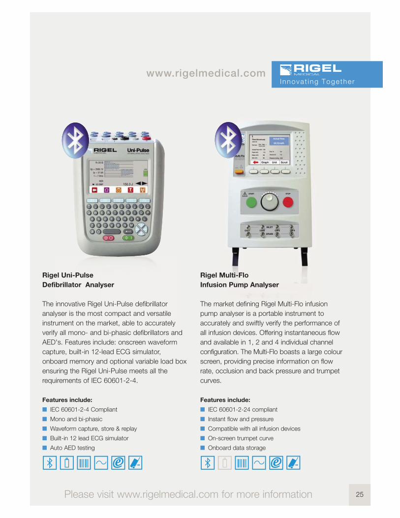
Rigel Multi-Flo
Infusion Pump Analyser
The market defining Rigel Multi-Flo infusion
pump analyser is a portable instrument to
accurately and swiftly verify the performance of
all infusion devices. Offering instantaneous flow
and available in 1, 2 and 4 individual channel
configuration. The Multi-Flo boasts a large colour
screen, providing precise information on flow
rate, occlusion and back pressure and trumpet
curves.
Features include:
n IEC 60601-2-24 compliant
n Instant flow and pressure
n Compatible with all infusion devices
n On-screen trumpet curve
n Onboard data storage
Rigel Uni-Pulse
Defibrillator Analyser
The innovative Rigel Uni-Pulse defibrillator
analyser is the most compact and versatile
instrument on the market, able to accurately
verify all mono- and bi-phasic defibrillators and
AED's. Features include: onscreen waveform
capture, built-in 12-lead ECG simulator,
onboard memory and optional variable load box
ensuring the Rigel Uni-Pulse meets all the
requirements of IEC 60601-2-4.
Features include:
n IEC 60601-2-4 Compliant
n Mono and bi-phasic
n Waveform capture, store & replay
n Built-in 12 lead ECG simulator
n Auto AED testing
26
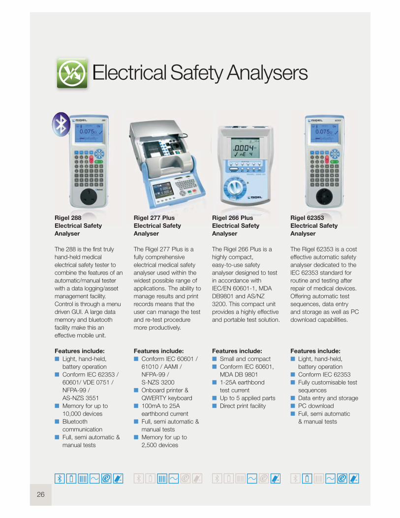
Electrical Safety Analysers
Rigel 266 Plus
Electrical Safety
Analyser
The Rigel 266 Plus is a
highly compact,
easy-to-use safety
analyser designed to test
in accordance with
IEC/EN 60601-1, MDA
DB9801 and AS/NZ
3200. This compact unit
provides a highly effective
and portable test solution.
Features include:
n Small and compact
n Conform IEC 60601,
MDA DB 9801
n 1-25A earthbond
test current
n Up to 5 applied parts
n Direct print facility
Rigel 62353
Electrical Safety
Analyser
The Rigel 62353 is a cost
effective automatic safety
analyser dedicated to the
IEC 62353 standard for
routine and testing after
repair of medical devices.
Offering automatic test
sequences, data entry
and storage as well as PC
download capabilities.
Features include:
n Light, hand-held,
battery operation
n Conform IEC 62353
n Fully customisable test
sequences
n Data entry and storage
n PC download
n Full, semi automatic
& manual tests
Rigel 288
Electrical Safety
Analyser
The 288 is the first truly
hand-held medical
electrical safety tester to
combine the features of an
automatic/manual tester
with a data logging/asset
management facility.
Control is through a menu
driven GUI. A large data
memory and bluetooth
facility make this an
effective mobile unit.
Features include:
n Light, hand-held,
battery operation
n Conform IEC 62353 /
60601/ VDE 0751 /
NFPA-99 /
AS-NZS 3551
n Memory for up to
10,000 devices
n Bluetooth
communication
n Full, semi automatic &
manual tests
Rigel 277 Plus
Electrical Safety
Analyser
The Rigel 277 Plus is a
fully comprehensive
electrical medical safety
analyser used within the
widest possible range of
applications. The ability to
manage results and print
records means that the
user can manage the test
and re-test procedure
more productively.
Features include:
n Conform IEC 60601 /
61010 / AAMI /
NFPA-99 /
S-NZS 3200
n Onboard printer &
QWERTY keyboard
n 100mA to 25A
earthbond current
n Full, semi automatic &
manual tests
n Memory for up to
2,500 devices
27
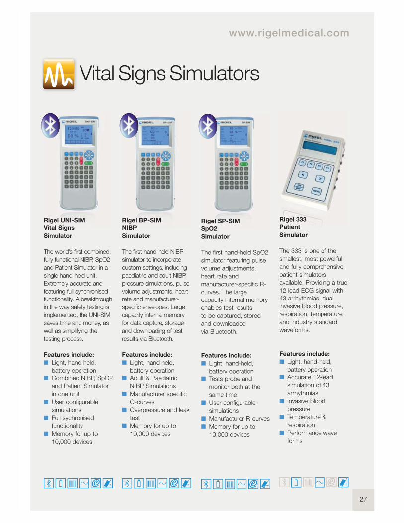
Vital Signs Simulators
www.rigelmedical.com
Rigel UNI-SIM
Vital Signs
Simulator
The world’s first combined,
fully functional NIBP, SpO2
and Patient Simulator in a
single hand-held unit.
Extremely accurate and
featuring full synchronised
functionality. A breakthrough
in the way safety testing is
implemented, the UNI-SIM
saves time and money, as
well as simplifying the
testing process.
Features include:
n Light, hand-held,
battery operation
n Combined NIBP, SpO2
and Patient Simulator
in one unit
n User configurable
simulations
n Full sychronised
functionality
n Memory for up to
10,000 devices
Rigel BP-SIM
NIBP
Simulator
The first hand-held NIBP
simulator to incorporate
custom settings, including
paediatric and adult NIBP
pressure simulations, pulse
volume adjustments, heart
rate and manufacturer-
specific envelopes. Large
capacity internal memory
for data capture, storage
and downloading of test
results via Bluetooth.
Features include:
n Light, hand-held,
battery operation
n Adult & Paediatric
NIBP Simulations
n Manufacturer specific
O-curves
n Overpressure and leak
test
n Memory for up to
10,000 devices
Rigel SP-SIM
SpO2
Simulator
The first hand-held SpO2
simulator featuring pulse
volume adjustments,
heart rate and
manufacturer-specific R-
curves. The large
capacity internal memory
enables test results
to be captured, stored
and downloaded
via Bluetooth.
Features include:
n Light, hand-held,
battery operation
n Tests probe and
monitor both at the
same time
n User configurable
simulations
n Manufacturer R-curves
n Memory for up to
10,000 devices
Rigel 333
Patient
Simulator
The 333 is one of the
smallest, most powerful
and fully comprehensive
patient simulators
available. Providing a true
12 lead ECG signal with
43 arrhythmias, dual
invasive blood pressure,
respiration, temperature
and industry standard
waveforms.
Features include:
n Light, hand-held,
battery operation
n Accurate 12-lead
simulation of 43
arrhythmias
n Invasive blood
pressure
n Temperature &
respiration
n Performance wave
forms

28
Med-eKit Elite
The Med-eKit Elite is a
handy and more
specialised carrying
solution. It has a hard-
wearing pelican case
which can be customised
to hold up to two
individual testers (the
Rigel 288 and UNI-SIM,
for instance). It can also
include a label and results
printer, barcode scanner
and PC software.
Features include:
n Configurable with up
to 4 tester functions
n Lightweight design
n Durable and robust
enclosure
n Water-proof design
n Secure locking
Med-eKit Lite
This new case is a
standard accessory for
the Rigel 288,
UNI-SIM and Uni-Pulse
biomedical testing
instruments. It can be
configured to hold a
number of different items
of test equipment and
accessories like
a label results printer and
a barcode scanner.
Features include:
n Carry securely on
back/ easy access
from front
n Configurable
compartments for
testers and accessories
n Extremely lightweight
design
n Suitable for up to 5
tester functions
n Durable and water
repellent design
Med-eKit Plus
The Med-eKit Plus is a
solution package offering
a complete test set that
includes electrical safety,
vital signs simulator,
ventilator tester and more.
It can also feature a laptop
of your specification
and our latest asset
management software.
You could make life a lot
more efficient for yourself
if you included a range of
accessories like the
compact barcode scanner
and results/label printer.
Features include:
n Cost effective package
deal
n Configurable including
up to 5 tester functions
n Optional laptop
included
n Extremely lightweight
design
n Durable and water
repellent design
Med-eKit Pro
If you’re after a complete
biomedical workshop on
wheels, take a look at our
configurable Rigel Med-
eKit Pro. Housed in a
durable and handy trolley
case, it accommodates up
to 10 different testers and
simulators, so you can
carry your analyser, vital
signs simulator, defib
analyser, ventilator tester
and more, safely and
conveniently.
Features include:
n Integral wheels and
extendable handle for
easy use
n Configurable with up
to 10 tester functions
n Durable and robust
enclosure
n Water-proof design
n Secure locking
Med-eKit Solutions

29
You saw database management and work order
schedules as a major benefit, as they lead to fast,
efficient test device configuration. You asked for time
and money-saving software to provide monthly schedule
tests you could upload to your testers for easy re-test.
You also wanted preventative maintenance which
analysed and compared results and which also sent you
an alarm when devices could be deteriorating or needed
to be replaced.
And you asked for test certificate software customisable
for details and logos in PDF format.
So we created Med-eBase software which can be
used in a number of database environments, including:
SQL and SQLite. This way your data’s secure and easily
accessible. It can also be easily interrogated by third
party software which makes compatibility with other
software packages easy and straightforward.
Asset Management Software
www.rigelmedical.com
Copyright © 2013 Rigel Medical
Part of
US Office
Rigel Medical, Seaward Group USA, 6304 Benjamin Road, Suite 506,
Tampa, Florida, 33634, United States
Tel: +1 813-886-2775 Email: [email protected]
Rigel Medical, Bracken Hill, South West Industrial Estate,
Peterlee, County Durham, SR8 2SW United Kingdom
Tel: +44 (0) 191 587 8730 Fax: +44 (0) 191 586 0227
Email:[email protected] Web: www.rigelmedical.com
Version 1.0 - 2013