an introduction to pantm technology - optimum …optimum-piping.com/01 new paradigms for pulsation...
TRANSCRIPT

An Introduction to PANTM Technology
New paradigms for pulsation attenuation, compression efficiency and increased flow. ____________________________________________________________________________________
A whitepaper published jointly by ACI Services Inc. and OPTIMUM Pumping Technology Rev 0 – Issued May 31, 2016
_____________________________________________________________________________________________
BACKGROUND Since the dawn of the natural gas industry, pulsation in pipes has been a misunderstood problem. Because pulsation causes vibration, vibration causes fatigue and fatigue causes potentially catastrophic failures, the accepted way to attenuate pulsation has been to dissipate its energy as quickly as possible with friction. Unfortunately, friction causes pressure loss which decreases compression efficiency. The long sought silver bullet is pulsation attenuation with negligible pressure loss.
The truth is that pulsation energy is valuable and should be conserved, not dissipated. PANTM systems are carefully designed pulsation attenuation pipe networks that cancel, interleave and reflect pulsation energy to conserve almost all of it. PANTM systems have been field‐proven to provide essential pulsation attenuation with negligible pressure loss7,13,14.
Pulsation is most often created by reciprocating compressors and resonance in system/yard piping. Traditional pulsation control systems employ combinations of primary and/or secondary volume bottles, often with complex internal choke tubes, baffles, and chambers, as well as external choke tubes and various orifice plates installed at specific locations in the system piping. These devices accomplish pulsation control by adding resistance, or damping, to the system; and they can cause significant system pressure losses upstream and downstream of the compressor cylinders. Although these systems may be well designed, the resulting pressure losses reduce overall system efficiency.
The reduction in pulsation vs. the increase in pressure loss trade‐off is tolerable for many high pressure ratio compressor applications. However, for common pipeline transmission applications having low pressure ratios (in the range of about 1.1 to 1.6), system pressure losses can severely degrade the compressor operating efficiency, especially when higher speed (>600 rpm) compressors are used. For example, a 20% loss of efficiency on an 8,000 HP compressor wastes 1,600 HP.
This loss of efficiency has become more significant in recent years as the U.S. pipeline industry has expanded its use of larger high‐speed reciprocating compressors. With the world’s increased awareness of the need for higher energy efficiency and a reduced carbon footprint, new more efficient pulsation attenuation systems are required now.
Reciprocating compressors and reciprocating engines have a great deal in common. Engines pump air and compressors pump natural gas. In the middle of the 20th century, racing engine designers discovered how to reflect pulsation energy to make a lot more horsepower to win races. This in turn stimulated academic curiosity and research. The engineering college at The Queens University of Belfast (QUB) became a center for the study of unsteady gas dynamics in pipes. Their faculty, led by Professor Gordon P. Blair

CBE, published hundreds of juried SAE and ASME papers on the theory and simulation of pulsation in engine intake and exhaust pipes.
In the 1990s, OPTIMUM Power Technology acquired the exclusive worldwide rights to the unsteady gas dynamic simulation software created by Prof. Blair and sponsored many years of research in this field at QUB. OPTIMUM Power Technology created and markets Virtual 2‐Stroke and Virtual 4‐Stroke engine simulation and design software products. Virtual 4‐Stroke has been used to design engines that have won the Indianapolis 500, the NASCAR Daytona 500, the Le Mans GT class, the $5 Million Progressive Automotive XPrize competition and many Formula SAE competitions. During the last decade, OPTIMUM Power Technology has upgraded the thermodynamics and gas dynamics calculations to properly simulate real gas mixtures using NIST gas properties. The result of this effort is the Virtual Pumping Station (VPSTM) simulation and design software product. The insight provided by VPS has enabled OPTIMUM Pumping Technology (OPT) and ACI Services Inc. (ACI) to create revolutionary improved products for the natural gas pipeline industry. These improved products include the PANTM Filter and the PANTM Manifold Hi‐Performance Compressor Manifold. AN INTRODUCTION TO PANTM FILTERS As applied to PAN Filters, PANTM is an acronym for Pulsation Attenuation Network, which is patent pending. PANTM Filters consist of one or more loops created with standard pipes and special junctions called Tuning Section Transitions collectors, TST collectors, or simply PAN Junctions. The loop lengths and diameters, together with the patent‐pending TST collectors, are engineered to substantially reduce pulsations and maximize flow in a pipe network without causing pressure drop. An example of a single PAN Filter Loop is shown in Figure 1.
Figure 1: Example of a single PANTM Filter Loop
Theory of Operation PAN Filters are a dramatic departure from traditional pulsation control bottles and represent a new way of thinking about pulsation control. Whereas bottles use restrictions like orifice plates and choke tubes to dissipate pulsation energy, PAN Filters attenuate pulsation without restrictions, pressure drop or energy loss. In a PAN Filter, the flow stream, as well as the pulsation energy, is carefully and equally split into two paths. Figure 2 illustrates the complete cancellation of the primary frequency using a single loop PAN Filter. Half of the pulsating flow travels through a loop that is longer, by one‐half wave length, than the short length of the flow path straight through the TST collector. When the two waves of equal amplitude
in the two flow paths are carefully rejoined 180˚out of phase, one wave completely cancels the other, eliminating the pulsation at that frequency in the downstream flow.
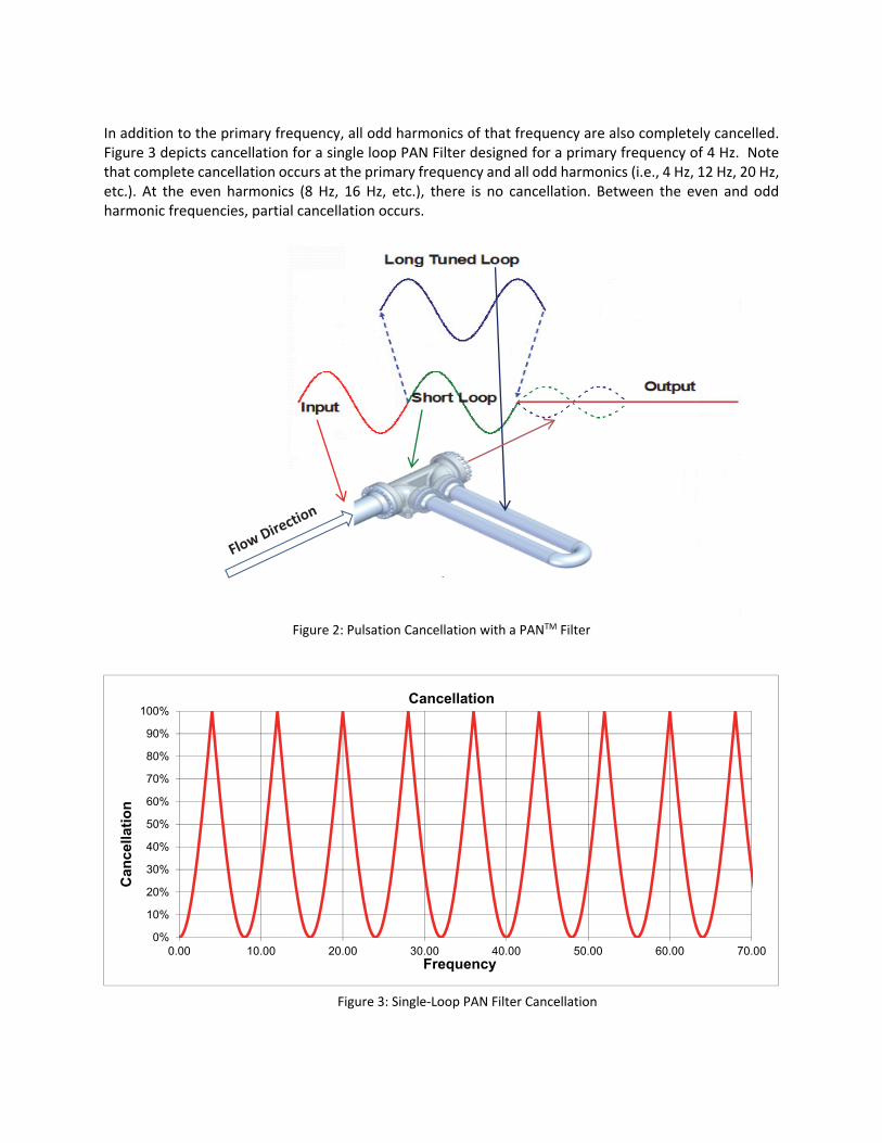
In addition to the primary frequency, all odd harmonics of that frequency are also completely cancelled. Figure 3 depicts cancellation for a single loop PAN Filter designed for a primary frequency of 4 Hz. Note that complete cancellation occurs at the primary frequency and all odd harmonics (i.e., 4 Hz, 12 Hz, 20 Hz, etc.). At the even harmonics (8 Hz, 16 Hz, etc.), there is no cancellation. Between the even and odd harmonic frequencies, partial cancellation occurs.
Figure 2: Pulsation Cancellation with a PANTM Filter
Figure 3: Single‐Loop PAN Filter Cancellation
TST
0%
10%
20%
30%
40%
50%
60%
70%
80%
90%
100%
0.00 10.00 20.00 30.00 40.00 50.00 60.00 70.00
Can
cella
tio
n
Frequency
Cancellation

Additional loops can be added in series to produce broad bands of pulsation attenuation that fill in the cancellation gaps between the odd and even orders of the primary frequency. Two or more loops may be necessary for applications with variable speed compressors, varying gas compositions and temperatures, varying flow velocities and flow streams with complex pulsation signatures. A 2‐loop PAN Filter is shown in Figure 4. Note that, when necessary, the footprint can be reduced by folding loop pipes over themselves. The graph in Figure 5 shows the effect of adding a second loop tuned to cancel 2.7 Hz and its odd harmonics. Note that this design completely cancels 8 Hz, the first even harmonic of the 4 Hz loop. The two loops in series result in at least 75% cancellation of all frequencies between 2 to 4.75 Hz, providing a broader band of attenuation.
Figure 4: 2‐Loop PAN Filter – Loops in Series
Figure 5: 2‐Loop PAN Filter Cancellation
The graph in Figure 6 shows the broad band of pulsation cancellation that can be achieved with a 4‐Loop PAN Filter. These loops are designed to cancel 4, 8, 16, and 32Hz. Note that 4Hz and all 14 harmonics of 4Hz up to 60Hz are completely canceled. In addition, note that all frequencies from 11Hz to 53Hz are attenuated by more than 90%.
0%
10%
20%
30%
40%
50%
60%
70%
80%
90%
100%
0.00 4.00 8.00 12.00 16.00
Can
cella
tio
n
Frequency
Cancellation
4.00 2.67 2 Comb

Figure 6: 4‐Loop PAN Filter Cancellation
While the pressure losses of conventional bottles and pulsation damping orifice plates are significant, as much as ¼ of line pressure in extreme cases that have been documented, pressure losses in PAN Filter systems are nearly zero, even in the highest transmission line flow cases. As a result, PAN Filters will increase operating efficiency, so that more flow can be produced for a given horsepower input, or less horsepower is required for a given flow rate. Either way, the use of a PAN Filter reduces operating cost and greenhouse gas (GHG) emissions. Applications PAN Filters can be used to attenuate pulsation in virtually any piping system. Specific target applications include the following. 1. PAN Filters can be applied to reduce harmful pulsations and associated shaking forces and pipe
stresses in reciprocating compressor suction and discharge headers, without any significant pressure losses. An example of a compact PAN Filter design for retrofit to the discharge header of an existing slow‐speed integral engine compressor is shown in Figure 7.
2. PAN Filters can be applied to effectively eliminate pulsations upstream of flow metering stations to increase measurement accuracy and reduce the risk of damage to the precision flow measurement instruments. In this application, PAN Filters are more effective than conventional pulsation bottles over a very wide range of flow rates, without any significant pressure losses. Figure 8 is an example of a PAN Filter being installed upstream of a large flow metering station in 2015.
3. PAN Filters can be used on lines upstream, or downstream, of centrifugal compressors to eliminate pulsations, without any significant pressure losses, that might otherwise create unsteady flow within the centrifugal compressor that would lead to premature surge and a reduction in its useful operating
0%
10%
20%
30%
40%
50%
60%
70%
80%
90%
100%
0.00 10.00 20.00 30.00 40.00 50.00 60.00 70.00
Can
cella
tio
n
Frequency
Cancellation
4.00 8.00 16.00 32.00 4 Comb
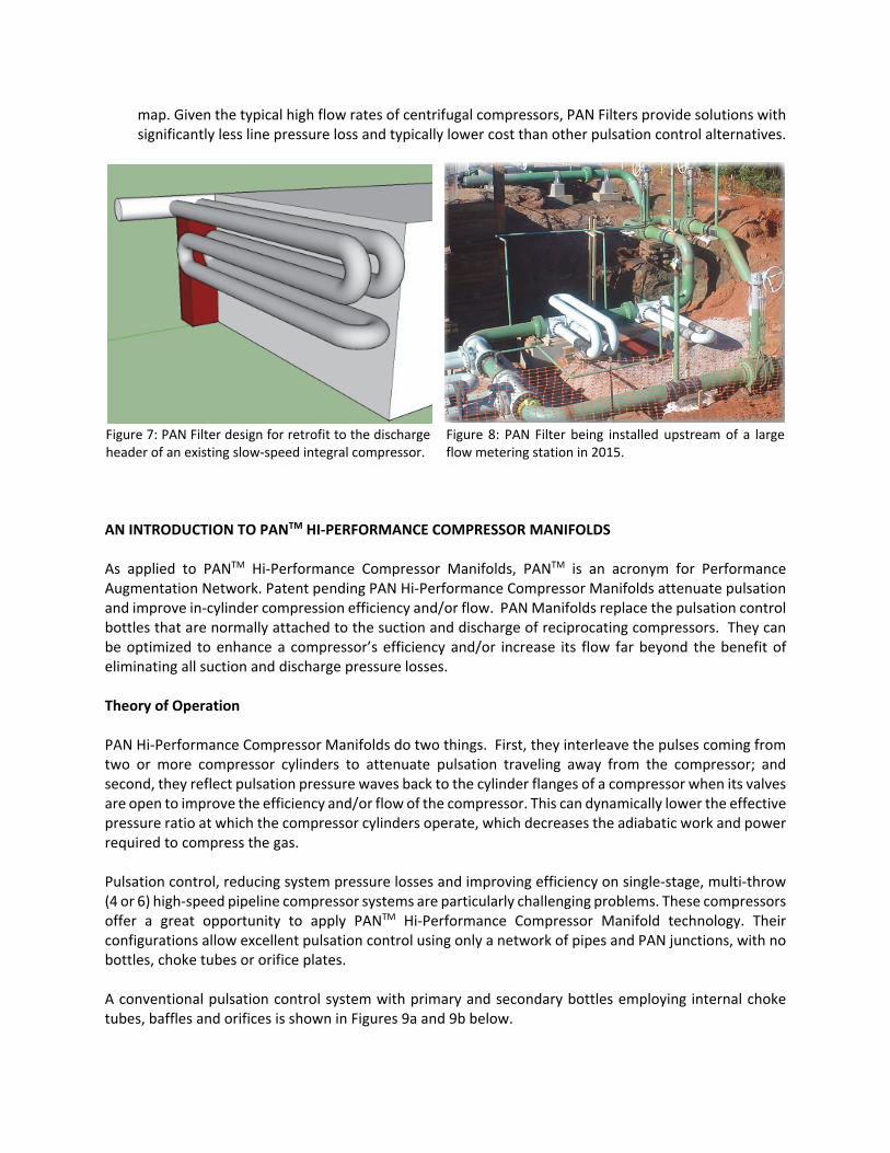
map. Given the typical high flow rates of centrifugal compressors, PAN Filters provide solutions with significantly less line pressure loss and typically lower cost than other pulsation control alternatives.
Figure 7: PAN Filter design for retrofit to the discharge header of an existing slow‐speed integral compressor.
Figure 8: PAN Filter being installed upstream of a large flow metering station in 2015.
AN INTRODUCTION TO PANTM HI‐PERFORMANCE COMPRESSOR MANIFOLDS As applied to PANTM Hi‐Performance Compressor Manifolds, PANTM is an acronym for Performance Augmentation Network. Patent pending PAN Hi‐Performance Compressor Manifolds attenuate pulsation and improve in‐cylinder compression efficiency and/or flow. PAN Manifolds replace the pulsation control bottles that are normally attached to the suction and discharge of reciprocating compressors. They can be optimized to enhance a compressor’s efficiency and/or increase its flow far beyond the benefit of eliminating all suction and discharge pressure losses. Theory of Operation PAN Hi‐Performance Compressor Manifolds do two things. First, they interleave the pulses coming from two or more compressor cylinders to attenuate pulsation traveling away from the compressor; and second, they reflect pulsation pressure waves back to the cylinder flanges of a compressor when its valves are open to improve the efficiency and/or flow of the compressor. This can dynamically lower the effective pressure ratio at which the compressor cylinders operate, which decreases the adiabatic work and power required to compress the gas. Pulsation control, reducing system pressure losses and improving efficiency on single‐stage, multi‐throw (4 or 6) high‐speed pipeline compressor systems are particularly challenging problems. These compressors offer a great opportunity to apply PANTM Hi‐Performance Compressor Manifold technology. Their configurations allow excellent pulsation control using only a network of pipes and PAN junctions, with no bottles, choke tubes or orifice plates. A conventional pulsation control system with primary and secondary bottles employing internal choke tubes, baffles and orifices is shown in Figures 9a and 9b below.
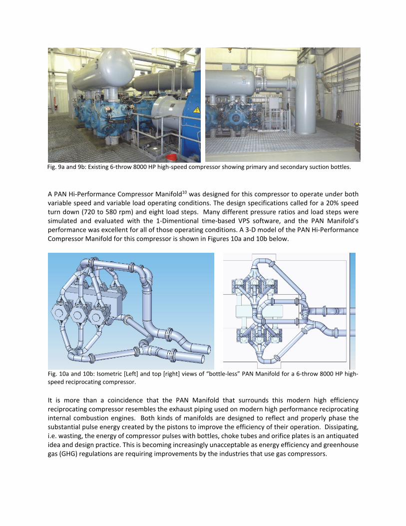
Fig. 9a and 9b: Existing 6‐throw 8000 HP high‐speed compressor showing primary and secondary suction bottles.
A PAN Hi‐Performance Compressor Manifold10 was designed for this compressor to operate under both variable speed and variable load operating conditions. The design specifications called for a 20% speed turn down (720 to 580 rpm) and eight load steps. Many different pressure ratios and load steps were simulated and evaluated with the 1‐Dimentional time‐based VPS software, and the PAN Manifold’s performance was excellent for all of those operating conditions. A 3‐D model of the PAN Hi‐Performance Compressor Manifold for this compressor is shown in Figures 10a and 10b below.
Fig. 10a and 10b: Isometric [Left] and top [right] views of “bottle‐less” PAN Manifold for a 6‐throw 8000 HP high‐speed reciprocating compressor.
It is more than a coincidence that the PAN Manifold that surrounds this modern high efficiency reciprocating compressor resembles the exhaust piping used on modern high performance reciprocating internal combustion engines. Both kinds of manifolds are designed to reflect and properly phase the substantial pulse energy created by the pistons to improve the efficiency of their operation. Dissipating, i.e. wasting, the energy of compressor pulses with bottles, choke tubes and orifice plates is an antiquated idea and design practice. This is becoming increasingly unacceptable as energy efficiency and greenhouse gas (GHG) regulations are requiring improvements by the industries that use gas compressors.

Efficient Tuning Section Transition (TSTTM) collectors, often called PAN Junctions, are critical to the performance of the PAN Manifold. Three 12 in. diameter primary pipes merge the flow and pulses from the three cylinders on each side of the compressor into a 3‐port TST collector. This was done for both the suction and the discharge on each side of the compressor. With the uniform phasing of the crankshaft throws, equal length header pipes will interleave and attenuate the pulses joined together at the 3‐port TST collector. Although not always necessary, this attenuation effect is most effective when all compressor cylinder ends are unloaded equally. Standard pipe and elbows are used for all of the piping between the cylinders and TST collector connections. The 16 in. diameter pipes on the two sides of the compressor are designed to have different lengths before being joined by 2‐port TST collectors on both suction and discharge. The different pipe lengths from the two 3‐port TST collectors to the 2‐port TST collectors are optimized to create a phase delay that interleaves the six pulses from each side of the compressor, which provides further pulsation attenuation. The large ends of the 2‐port TST collectors connect to existing 24 in. diameter station suction and discharge pipe legs coming into the compressor building from the main headers. The suction PAN Manifold system is mounted overhead on a pipe deck as shown in Figures 11a and 11b. This structure is similar to what is employed in chemical plants. For this large unit, it is rigidly constructed and mounted on concrete piers. For smaller skid‐mounted units, it can be integrated into the skid design. Thorough FEA modeling ensures that there is adequate stiffness to support and restrain the PAN Manifold piping overhead during operation. Sufficient space is provided underneath the pipe deck for accessing the frame top cover, and a monorail can be added for frame maintenance if desired.
Figures 11a and 11b: Isometric views of PAN Manifold system with suction pipe deck and part of floor decking in place.
Figures 12a and 12b compare the simulated suction and discharge pulsation at the pipeline upstream and downstream of the PAN Manifold and bottle systems over the 580 to 720 rpm speed range at a 1.2 pressure ratio with no unloading10. In this case the PAN’s maximum suction pulsation was 4.3 psi (0.7% of line pressure) and maximum discharge pulsation was less than 3.4 psi (0.5% of line pressure). Both are well within industry standards. Throughout this paper the term “fully loaded” refers to “no compressor unloading” and does not refer to the motor or engine driver load.
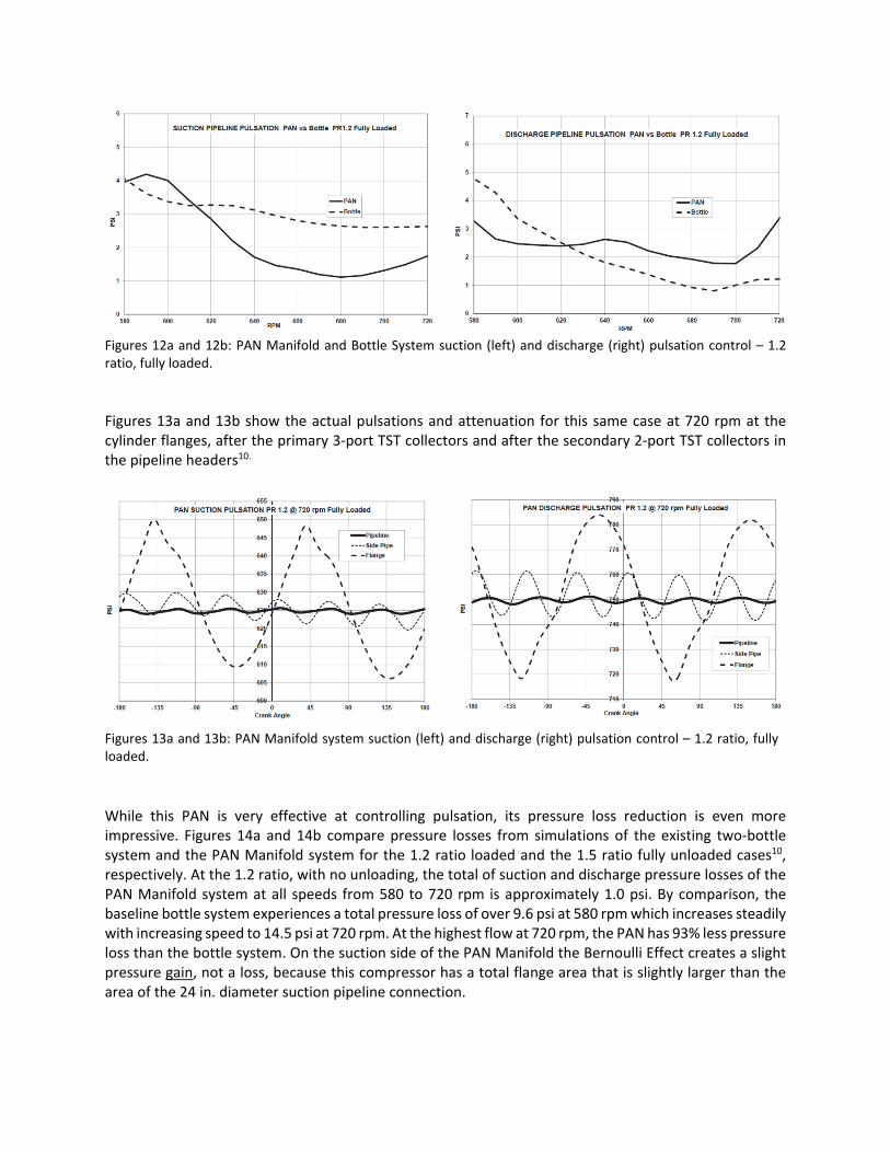
Figures 12a and 12b: PAN Manifold and Bottle System suction (left) and discharge (right) pulsation control – 1.2 ratio, fully loaded.
Figures 13a and 13b show the actual pulsations and attenuation for this same case at 720 rpm at the cylinder flanges, after the primary 3‐port TST collectors and after the secondary 2‐port TST collectors in the pipeline headers10.
Figures 13a and 13b: PAN Manifold system suction (left) and discharge (right) pulsation control – 1.2 ratio, fully loaded.
While this PAN is very effective at controlling pulsation, its pressure loss reduction is even more impressive. Figures 14a and 14b compare pressure losses from simulations of the existing two‐bottle system and the PAN Manifold system for the 1.2 ratio loaded and the 1.5 ratio fully unloaded cases10, respectively. At the 1.2 ratio, with no unloading, the total of suction and discharge pressure losses of the PAN Manifold system at all speeds from 580 to 720 rpm is approximately 1.0 psi. By comparison, the baseline bottle system experiences a total pressure loss of over 9.6 psi at 580 rpm which increases steadily with increasing speed to 14.5 psi at 720 rpm. At the highest flow at 720 rpm, the PAN has 93% less pressure loss than the bottle system. On the suction side of the PAN Manifold the Bernoulli Effect creates a slight pressure gain, not a loss, because this compressor has a total flange area that is slightly larger than the area of the 24 in. diameter suction pipeline connection.

At the low flow 1.5 pressure ratio conditions, the PAN Manifold pressure loss is 0.3 psi or less. Under the same operating conditions, the current bottle system has a total pressure loss ranging from 4.6 psi at 580 rpm to 8.2 psi at 720 rpm. At 720 rpm the PAN has 96% less pressure loss than the bottle system.
Figures 14a and 14b: PAN Manifold and Bottle System pressure loss – 1.2 ratio, fully loaded (left) & 1.5 ratio, fully unloaded (right).
Figures 15a and 15b show the efficiency of both systems measured in BHP/MMSCFD and the % PAN Manifold efficiency improvement10. The PAN Manifold’s efficiency is 15% better at 720 rpm and it averages more than 12% over the speed range.
Figures 15a and 15b: PAN vs. Bottle System ‐ 1.2 ratio fully loaded Bhp/MMSCFD (left) & % Efficiency Improvement (right).
The VPS design and analysis software allows the engineer to obtain pressure vs. volume diagrams for any head or crank end of a virtual compressor using its Virtual Data Acquisition system. Figure 16 compares the PV diagrams of the same cylinder head‐end for both the PAN Manifold and bottle systems10. The suction pipeline pressure is 625 psi and the discharge pipeline pressure is 750 psi, resulting in a 1.2 pressure ratio. The area within the curves is proportional to the work that the cylinder end does to pump the gas. It is obvious to see in Figure 16 that the PAN Manifold cylinder end does less work than the bottle system to pump the same amount gas and is therefore much more efficient. To understand why this is true, it is necessary to see and understand how the PAN Manifold has been designed to improve the cyclical pressure fluctuations at the cylinder flanges.
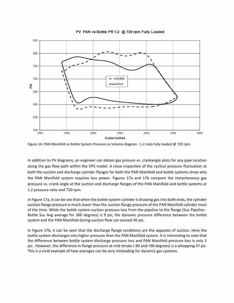
Figure 16: PAN Manifold vs Bottle System Pressure vs Volume diagram ‐ 1.2 ratio fully loaded @ 720 rpm.
In addition to PV diagrams, an engineer can obtain gas presure vs. crankangle plots for any pipe location
along the gas flow path within the VPS model. A close inspection of the cyclical pressure fluctuation at
both the suction and discharge cylinder flanges for both the PAN Manifold and bottle systems show why
the PAN Manifold system requires less power. Figures 17a and 17b compare the instantaneous gas
pressure vs. crank angle at the suction and discharge flanges of the PAN Manifold and bottle systems at
1.2 pressure ratio and 720 rpm.
In Figure 17a, it can be see that when the bottle system cylinder is drawing gas into both ends, the cylinder suction flange pressure is much lower than the suction flange pressure of the PAN Manifold cylinder most of the time. While the bottle system suction pressure loss from the pipeline to the flange (Suc Pipeline ‐ Bottle Suc Avg average for 360 degrees) is 9 psi, the dynamic pressure difference between the bottle system and the PAN Manifold during suction flow can exceed 30 psi. In Figure 17b, it can be seen that the discharge flange conditions are the opposite of suction. Here the bottle system discharges into higher pressure than the PAN Manifold system. It is interesting to note that the difference between bottle system discharge pressure loss and PAN Manifold pressure loss is only 3 psi. However, the difference in flange pressure at mid‐stroke (‐90 and +90 degrees) is a whopping 47 psi. This is a vivid example of how averages can be very misleading for dynamic gas systems.

Figures 17a and 17b: PAN Manifold vs. Bottle System Suction and Discharge Flange pressure vs. crank angle ‐ 1.2 ratio no unloading @ 720 rpm.
In conclusion, conventional bottle systems are designed to dissipate the energy in the pulses that come out of reciprocating compressor cylinders. The pulse energy is treated as a problem that must be eliminated as quickly as possible. A well designed PAN Manifold does exactly the opposite. Rather than dissipate pulse energy, a PAN Manifold uses it to make the compressor operate more efficiently, while simultaneously attenuating pulsation at the pipeline to very low levels. ACI Services Inc. and OPTIMUM Power Technology have used the Virtual Pumping Station and Automated Design systems to change the phasing and amplitude of the gas pulsation at the flanges to maximize the cylinder’s adiabatic pumping efficiency. This patent‐pending technology is a major breakthrough in improving the efficiency of high‐speed reciprocating compressors. Applications PAN Hi‐Performance Compressor Manifolds can be used with any reciprocating compressor system, but the highest performance benefits are on low pressure‐ratio 2‐throw, 4‐throw and 6‐throw single‐stage reciprocating compressors as well as on multi‐stage compressors having 2‐throws or 3‐throws per stages. Specific target applications of PAN Manifolds include the following examples. In many cases all the applications can be met with a single optimized PAN Manifold design. 1. PAN Manifolds can be applied to attenuate the detrimental gas pulsations created by reciprocating
compressors, preventing them from traveling upstream and downstream from the pumping station.
2. PAN Manifolds can be applied to reduce the vibrations caused by pulsation bottles. In PAN Manifold systems, pulsations are reduced significantly at the first manifold junction. This means that the high amplitude pressure pulsation acts only on the relatively short smaller diameter header pipes (12 in. in this example), rather than the much larger diameter (up to 60 in.) bottles. It is estimated that the resulting shaking forces can be 25% to 90% lower, which will reduce vibration related failures and increase the mean time between failures for the compressor.

3. PAN Manifolds can be used to minimize pressure losses on both the suction and discharge sides of the compressor. There are no baffles, choke tubes or orifice plates to impede gas flow, as the pulsation bottles can be com‐pletely eliminated from the system. Figure 18 is an early example of a combination PAN Manifold and PAN Filter system that was retrofitted on a 4‐throw, single‐stage 1000 rpm recipro‐cating compressor in 2009.
Figure 18: Early example of a combination PAN Manifold and PAN filter retrofitted to an existing 1000 rpm compressor in 2009.
4. PAN Manifold technology can be used to significantly reduce the compression horsepower
requirement or increase the compressor flow for a given power rating. Utilizing 1‐D unsteady gas dynamic simulation software that has been successfully applied to high‐performance engines for at least two decades, optimized PAN Manifold configurations can boost the suction pressure during the compressor cylinders’ suction events and reduce the discharge pressure during the cylinders’ discharge events. Combining this with the aforementioned reduction of system pressure losses can typically reduce pipeline compression energy costs by 10% to 20% or more. Figure 19 shows a 4‐throw, single stage 1400 rpm compressor with a Hi‐Performance PAN Compressor Manifold installed in 2015, which increased efficiency enough to permit the use of larger compressor cylinders to significantly increase the unit’s capacity compared to what was possible with a comparable bottle‐equipped system. Figure 20 shows a next generation Hi‐Performance PAN Compressor Manifold designed for a 6‐throw, single‐stage 750 rpm compressor.
Figure 19: A 4‐throw, single‐stage 1400 rpm compressor with a Hi‐Performance PAN Com‐pressor Manifold installed in 2015.
Figure 20: Next generation Hi‐Performance PAN Compressor Manifold designed for a 6‐throw, single‐stage 750 rpm compressor.

SUMMARY Lab testing and field installations have successfully demonstrated that PAN Filters and PAN Hi‐Performance Compressor Manifolds effectively control pulsations while significantly increasing reciprocating compressor system efficiency and capacity. Using advanced VPSTM simulation software, optimal PAN systems can be designed and the performance reliably predicted for the wide range of operating conditions that are typical of most reciprocating compressor applications. Several key advantages have driven end users’ interest and commitment toward the successful introduction of PAN technology in actual field applications. In addition to a fundamental interest in supporting the advancement of new compression technology, the end users saw the potential for significant commercial benefit by delivering more flow from compressors for a given driver size and energy input. The potential increases in flow and efficiency expected from the PAN system reduce fuel cost and exhaust emissions on a specific power basis. Such advancements may soon become mandatory as new regulations emerge from recently announced government initiatives to increase natural gas compressor efficiency and reduce greenhouse gas emissions. In cases where multiple units are paralleled in a station, the PAN technology offers the potential to reduce capital cost by reducing the number and/or size of the required drivers and compressors.
REFERENCES 1. Harris, R. and Raymer, R., The Value ($$) of Compressor Efficiency, 2006 GMC Short Course,
Oklahoma City, OK, October 5, 2006. 2. Greenfield, S. D., Optimizing Compressor Design for Complex Reciprocating Installations, 2006 GMRC
Gas Machinery Conference, October 2‐4, 2006. 3. Buller, P.; Eberle, K. Fernandez, J.; Hickman, D.; Integrating Compressor Performance with the Effects
of Pressure Pulsation Across a Unit’s Entire Operating Map, 2007 GMRC Gas Machinery Conference. 4. Brahler, C.; Chatfield, G.; Crandall, J; and Shade, W.; An Investigation of the Application of Finite
Amplitude Wave Simulation with a New Technology for Controlling reciprocating Compressor Pulsations, 2007 GMRC Gas Machinery Conference.
5. Chatfield, G.; Crandall, J.; Shade, W.; and Wells, D.; Demonstration of Efficient Compressor Control Using Tuned Loop Networks, 2008 GMRC Gas Machinery Conference.
6. Chatfield, G. and Shade, W.; New Technology for the Efficient Cancellation of Compressor Pulsations, GMC Journal, February 2009.
7. Bazaar, J.; Chatfield, G.; Crandall, J.; Shade, W. and Wells, D.; Efficient Bottle‐Less Compressor Pulsation Control – Experimental Test Results, 2009 GMRC Gas Machinery Conference.
8. Shade, W.; Efficient Bottle‐Less Compressor Pulsation Control, GMC Today, October 2009. 9. Chatfield, G. and Shade, W.; Thinking Outside the Bottle: Attenuate Pulsation and Eliminate 90% of
All Pressure Losses, GM Journal, May 2011. 10. Chatfield, G. and Shade, W.; Thinking Outside the Bottle: The Use of Performance Augmentation
Networks to Increase Compressor Efficiency, 2011 GMRC Gas Machinery Conference. 11. Gas Machinery Research Council; GMRC Guideline for High‐Speed Reciprocating Compressor
Packages for Natural Gas Transmission & Storage Applications, Release 1.3, July 19, 2013. 12. Arjmands, M., Bazaar, J., Chatfield, G., Eberle, K., Schubring, S., Shade, W., and Wells, D., Design and
Field Test of a Full Scale Performance Augmentation Network (PAN), 2014 GMRC Gas Machinery Conference.

13. Gas Machinery Research Council; Final Report Executive Summary, Rev. 3, Reciprocating Compressor Performance Augmentation Network (PAN) Technology Full‐Scale Field Test Results – Short Course, 2015 GMRC Gas Machinery Conference.
14. Gas Machinery Research Council; Reciprocating Compressor Performance Augmentation Network (PAN) Technology Full‐Scale Field Test Results – Short Course Presentation Slides, 2015 GMRC Gas Machinery Conference.
15. ACI Services Inc. & Optimum Pumping Technology Inc.; The Theory of PANTM Systems, May 2016.