an introduction to unified modeling language (uml) in ... · university of south-eastern norway...
TRANSCRIPT

University of South-Eastern Norway Page 1February 4, 2019
Nils-Olav Skeie
An introduction toUnified Modeling Language (UML)inSoftware Engineering

University of South-Eastern Norway Page 2February 4, 2019
Overview
• Introduction,
– Software development process
• Analysis,
– Use Case,
• Design,
– Interaction diagrams,
– Class diagram,
• Testing,
• Conclusion.UML: Use Case diagram
University of South-Eastern Norway Page 3February 4, 2019
Why is developing software so hard?
• Users don’t know what they want until they see it,– They only think that they know what they want.
– How to understand the need(s) of the user(s)?
• Lack of user input,– Management decisions, users too busy, poor user involvement,..
• Programming is easy,– Easy to learn how to write code, but huge gap between that and making great software,
– Software coding is probably the easiest part of being a software engineer,
• Every line of code is a potential point of failure,
• The software industry is young,
• Estimating time is an art, not science,
• Software application is like an iceberg – 90% of the complexity is not visible!
University of South-Eastern Norway Page 4February 4, 2019
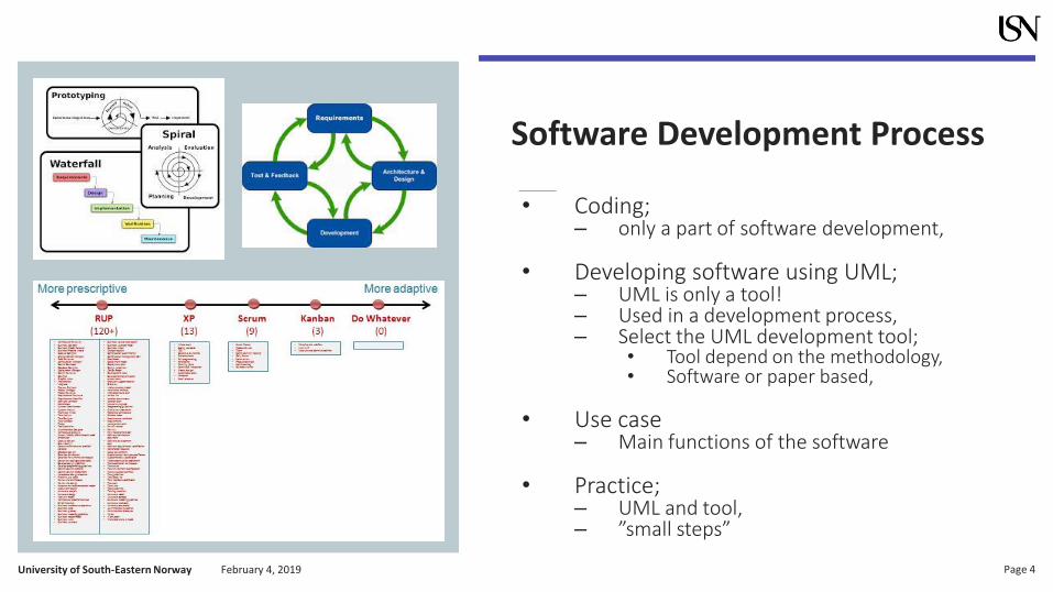
Software Development Process
• Coding;– only a part of software development,
• Developing software using UML;– UML is only a tool!– Used in a development process,– Select the UML development tool;
• Tool depend on the methodology,• Software or paper based,
• Use case– Main functions of the software
• Practice;– UML and tool,– ”small steps”
University of South-Eastern Norway Page 5February 4, 2019
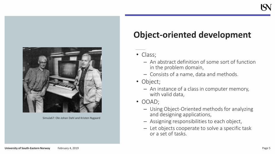
Object-oriented development
• Class;– An abstract definition of some sort of function
in the problem domain, – Consists of a name, data and methods.
• Object;– An instance of a class in computer memory,
with valid data,
• OOAD;– Using Object-Oriented methods for analyzing
and designing applications,– Assigning responsibilities to each object,– Let objects cooperate to solve a specific task
or a set of tasks.
Simula67: Ole-Johan Dahl and Kristen Nygaard

University of South-Eastern Norway Page 6February 4, 2019
UML diagram tools
Handmade or computer based diagrams,• Visio• StarUML;
– A Delphi based open-source UML platform for MS-Windows,
– Support C#, Java, and C++,• Rational Rose (Rational, IBM);
– License fee, expensive,• ArgoUML;
– a Java-based open source free UML modeling tool,– Support Java,
• Umbrello;– part of the KDE user interface of Linux,– Support C++/Java/Perl/PHP/Python++,
• Rhapsody;– embedded and real-time systems.
• +++++
University of South-Eastern Norway Page 7February 4, 2019
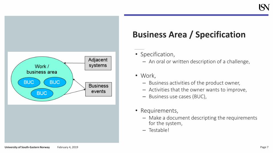
Business Area / Specification
• Specification,– An oral or written description of a challenge,
• Work,– Business activities of the product owner, – Activities that the owner wants to improve,– Business use cases (BUC),
• Requirements,– Make a document descripting the requirements
for the system,– Testable!

University of South-Eastern Norway Page 8February 4, 2019
Exercise: Business Area / BUC
• Software for a Washing Machine
– Specification?
– Business Use Cases?
– Requirements?
University of South-Eastern Norway Page 9February 4, 2019
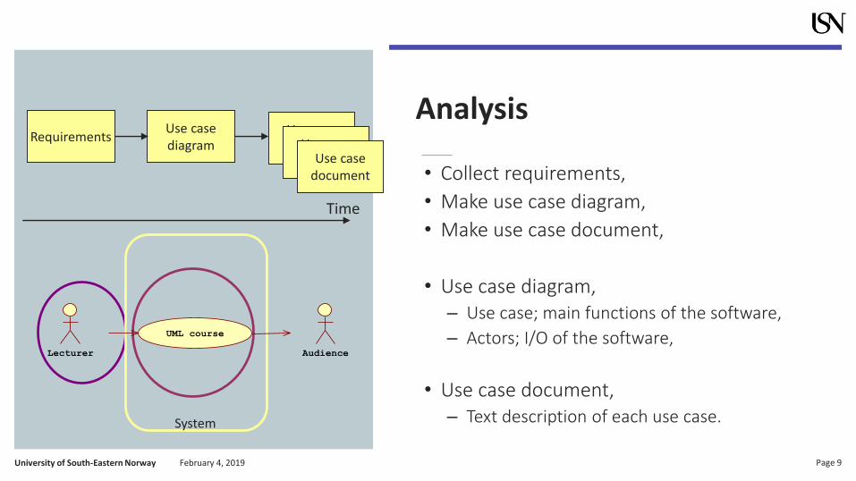
Analysis
• Collect requirements,
• Make use case diagram,
• Make use case document,
• Use case diagram,– Use case; main functions of the software,
– Actors; I/O of the software,
• Use case document,– Text description of each use case.
RequirementsUse casediagram
Use casedocument
Time
Use casedocumentUse case
document
System
Lecturer
UML course
Audience

University of South-Eastern Norway Page 10February 4, 2019
Requirements
• Use the FURPS+ letters, make a text document;– F is Functionality;
• Main functions of the software, the use cases, starts with a verb,
– U is Usability;• How to interact with the software, human factors, help,
documentation,
– R is Reliability;• Predictability, Accuracy, Mean time to failure,
– P is Performance;• Speed, Resource consumption, Throughput, Response
time,
– S is Supportability;• Testability, Adaptability, Maintainability, Configurability,
– + (extra)• Implementation, licenses, administration, interface to
external systems,
UseCase
Actors?Result:
• Functional
• Non-Functional Requirements

University of South-Eastern Norway Page 11February 4, 2019
Use case diagram
• How software will fulfill the requirements of the external actors,
• Functional section from the requirements,• Consists of a set of actors and use cases,• Actor
– ”something” requires a function or service of the software,
– Often a person, hardware device, software function (OS) or another computer system,
• Use case– Main functions of the applications,– The functions required to/from the actors,– Use a verb in the use case name,– More details for each use case in a use case
document.
University of South-Eastern Norway Page 12February 4, 2019
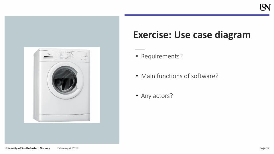
Exercise: Use case diagram
• Requirements?
• Main functions of software?
• Any actors?
University of South-Eastern Norway Page 13February 4, 2019
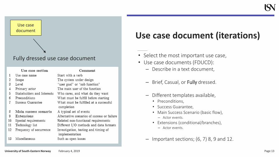
Use case document (iterations)
• Select the most important use case,• Use case documents (FDUCD):
– Describe in a text document,
– Brief, Casual, or Fully dressed.
– Different templates available,• Preconditions, • Success Guarantee,• Main Success Scenario (basic flow),
– Actor events.
• Extensions (conditional/branches),– Actor events.
– Important sections; (6, 7) 8, 9 and 12.
Fully dressed use case document
Use casedocument

University of South-Eastern Norway Page 14February 4, 2019
Analysis: Documents
• Specification and Requirements,– FURPS+,
– Text,
• Use case diagram,– UML,
– Main functions and actors,
• Use case document,– Text,
– Description of each use case,
– One document for each use case.
RequirementsUse casediagram
Use casedocument
Time
Use casedocumentUse case
document
Documentations – part of:• (SRS: Software Requirements & Specifications)• SRD: Software Requirements and Design
University of South-Eastern Norway Page 15February 4, 2019
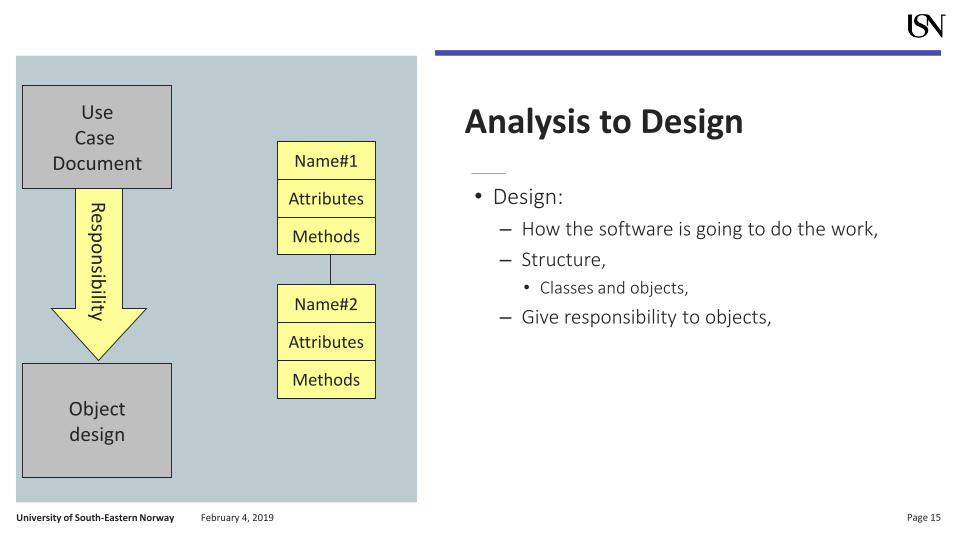
Analysis to Design
• Design:
– How the software is going to do the work,
– Structure,
• Classes and objects,
– Give responsibility to objects,
Resp
on
sibility
Objectdesign
Name#1
Attributes
Methods
Name#2
Attributes
Methods
UseCase
Document

University of South-Eastern Norway Page 16February 4, 2019
Giving responsibility to objects
Two types of responsibilities:
• knowing 1. private encapsulated data,
2. related objects,
3. “things” it can derive or calculate
• doing 1. doing something itself (creating an
object or doing a calculation),
2. initiating action in other objects,
3. controlling and coordinating activities in other objects.

University of South-Eastern Norway Page 17February 4, 2019
Design Model
• Describe the scenario of a use case with collaborating objects,
• The system operation starts with a controller object,
• Use UML diagrams
– interaction diagrams,
– class diagrams,
Design tasks:
1. Select the most important use case,
2. Select a controller class for this use case,
3. Make interaction diagrams for the use case,
4. Make a class and object diagram.

University of South-Eastern Norway Page 18February 4, 2019
Interaction diagrams- Sequence diagram
• Shows the sequence of the messages in time,
• Simple notation,
• Takes a lot of horizontal space,
• Notation (”UML” Coding):
– No answer: message()
– With answer: ans:=message()
– Condition: [x<10]:ans:=message()
– Loop: *[i=1..n]: ans:=message()
OOADP Intro UML WEB GRASP BookMain UML tool Display
1 : make_presentation()2 : txt := get_uml_infi()
3 : txt := get_grasp_info()
4 : combine_info()
5 : make_demo()
6 : demo1 := analysis()
7 : demo2 := design()
8 : presentation()9 : show(analysis)
10 : show(demo1)
11 : show(design)
12 : show(demo2)
University of South-Eastern Norway Page 19February 4, 2019
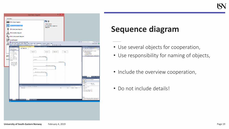
Sequence diagram
• Use several objects for cooperation,
• Use responsibility for naming of objects,
• Include the overview cooperation,
• Do not include details!

University of South-Eastern Norway Page 20February 4, 2019
Exercise: Sequence diagram
• Washing cloth at 40 deg. C
University of South-Eastern Norway Page 21February 4, 2019
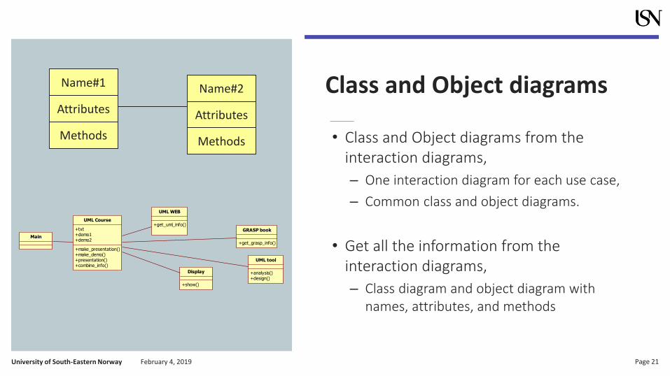
Class and Object diagrams
• Class and Object diagrams from the interaction diagrams,
– One interaction diagram for each use case,
– Common class and object diagrams.
• Get all the information from the interaction diagrams,
– Class diagram and object diagram with names, attributes, and methods
UML Course
+txt+demo1+demo2
+make_presentation()+make_demo()+presentation()+combine_info()
UML WEB
+get_uml_info()GRASP book
+get_grasp_info()
UML tool
+analysis()+design()
Display
+show()
Main
Name#1
Attributes
Methods
Name#2
Attributes
Methods
University of South-Eastern Norway Page 22February 4, 2019
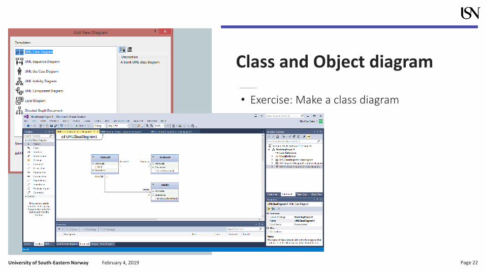
Class and Object diagram
• Exercise: Make a class diagram

University of South-Eastern Norway Page 23February 4, 2019
Design: Documents
• Interaction diagram,– Sequence diagram, focus on time,
– One diagram for each use case document,
– Dynamic model of your software,
• Class diagram,– Static model of your software,
– One common diagram,
• Object diagram,– Static model of your application,
– One common diagram.
Objectdiagram
Classdiagram
Time
InteractiondiagramInteraction
diagramInteractiondiagram
Documentations – part of:
• (SDD: Software Design Document)• SRD: Software Requirements and Design

University of South-Eastern Norway Page 24February 4, 2019
Testing
• More than 50% of errors may arise before coding,
• Testing in each iteration,
• Deploy an early version for the customer,
• For testing:– Requirements,– Use Case Diagram,– Use Case Documents (Fully Dressed Use Case
Document),
• Make a test plan; Description/Setup and test cases,
• All test documents produced before coding.
University of South-Eastern Norway Page 25February 4, 2019
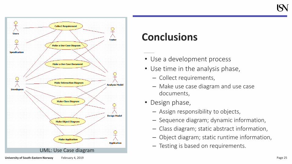
Conclusions
• Use a development process
• Use time in the analysis phase,– Collect requirements,
– Make use case diagram and use case documents,
• Design phase,– Assign responsibility to objects,
– Sequence diagram; dynamic information,
– Class diagram; static abstract information,
– Object diagram; static runtime information,
– Testing is based on requirements.UML: Use Case diagram