an investigation into design concepts, design methods and
TRANSCRIPT

HAL Id: hal-02294169https://hal.archives-ouvertes.fr/hal-02294169
Submitted on 23 Sep 2019
HAL is a multi-disciplinary open accessarchive for the deposit and dissemination of sci-entific research documents, whether they are pub-lished or not. The documents may come fromteaching and research institutions in France orabroad, or from public or private research centers.
L’archive ouverte pluridisciplinaire HAL, estdestinée au dépôt et à la diffusion de documentsscientifiques de niveau recherche, publiés ou non,émanant des établissements d’enseignement et derecherche français ou étrangers, des laboratoirespublics ou privés.
An investigation into design concepts, design methodsand stability criteria of salt caverns
Rahim Habibi
To cite this version:Rahim Habibi. An investigation into design concepts, design methods and stability criteria of saltcaverns. Oil & Gas Science and Technology - Revue d’IFP Energies nouvelles, Institut Français duPétrole (IFP), 2019, 74, pp.14. �10.2516/ogst/2018066�. �hal-02294169�

An investigation into design concepts, design methods and stabilitycriteria of salt cavernsRahim Habibi*
Msc in Tunneling and Underground Spaces, Urmia University, Urmia, Iran
Received: 24 April 2018 / Accepted: 18 September 2018
Abstract. Salt rock has been used as hast rock to storing hydrocarbons and disposing nuclear wastes becauseof its low permeability. On other hand it deforms under even low deviatoric stress which threatens the struc-tural stability of salt caverns. Rock mechanical stability is one of important stages in salt cavern’s design andconstruction, though mechanical factors (such as nonlinear behavior of rock salt), thermal factors (such astemperature changes during injection and production) and hydraulic factors (such as salt permeability andviscosity of stored material) affect on short term and long term behavior of salt cavern. Various criteria andmethods have been investigated for salt cavern’s design and stability analysis. In this paper, by taking intoaccount the importance of structural stability of salt cavern, the general behavior of rock salt and salt cavernare given. It reviews the various design concepts and methods and, in the following, stability criteria includingstress-based and damage-based are also discussed. It is assigned that the RD stability criterion is more compre-hensive than others.
1 Introduction
Application of underground storage to storing oil and nat-ural gas has been enhanced. One of the storing method isestablishing the cavity in salt beds or domes. Salt rockbecause of its low permeability, self-healing of damageand good creep characteristics has been seen as a perfectmedium for energy storage. It is widely accepted to storeenergy and resources in deep salt caverns. Table 1 givessome advantages and disadvantages of rock salt using forenergy storage. Because of special features of rock salt suchas low permeability and self-healing, not only these cavitieshave been used for oil or natural gas, but also it is bestoption to isolate nuclear wastes. In addition to naturalgas, hydrogen and compressed air used to generate electric-ity also are stored which needs a new operation scenario.These new salt cavern operating modes raise new mechan-ical issues, particularly illustrated by spalling observed atthe walls of some existing caverns.
Design, construction and operation (short term and/orlong term) of these cavities as well as abandoning of themrelate to short and long term structural stability from whichthe integrity of rock salt must be satisfied. So, due to stabil-ity satisfaction and damage suppression of walls and roof ofcavern, the condition of microcrack generation must not bemet based on stability criteria. It comes very importantwhen a large flexibility of the operation of a salt cavern is
required, as the stored material should be available forwithdrawal at any point in the year with a preferably highrate.
The mechanical damage changes the hydrogeologicalproperties of the zone surrounding an underground storagein rock by creating an Excavation Disturbed Zone (EDZ).Within the zone around underground facilities, rock saltdilates. As a matter of fact, its pore pressure decreases,the rock mass becomes partially unsaturated and its perme-ability increases. So, the stored material can migratethrough EDZ zone which causes environmental problems.Some of the problems and accidents that have beenoccurred in salt caverns are given in Table 2.
Creep low is applied as first step during cavern designprocess which must take all aspects of salt behavior.Through the years, many creep laws have been developedfor rock salt. Their complexity has increased, includingnew aspects of salt behavior. Development of the creep lowscomprises in three steps. First attempts in developing thecreep lows focused on general behavior of strain-time curveby which only transient and/ or stationary creep strainwould be determined, such as Norton–Hoff (Berest et al.,2008), Lemaitre (Tijani et al., 1983), Lubby2 (Heusermannet al., 2003) and Munson–Dawson (Munson and Dawson,1981). These lows have been applied to correlate the strain –time curve in different temperature and stress by takinginto account creep mechanism map. Over the years, in1990’s decade, more phenomena such as dilatancy andhealing were included by developing new lows, for instance* Corresponding author: [email protected]
This is an Open Access article distributed under the terms of the Creative Commons Attribution License (http://creativecommons.org/licenses/by/4.0),which permits unrestricted use, distribution, and reproduction in any medium, provided the original work is properly cited.
Oil & Gas Science and Technology - Rev. IFP Energies nouvelles 74, 14 (2019) Available online at:� R. Habibi, published by IFP Energies nouvelles, 2019 ogst.ifpenergiesnouvelles.fr
https://doi.org/10.2516/ogst/2018066
REGULAR ARTICLEREGULAR ARTICLE

in SUVIC (Aubertin et al., 1991), Cristescu (Cristescu,1993), or Gunther–Salzer (Gunther et al., 2010). In lastyears, in third step, early models were improved to takeinto account more phenomena as well: A version of
Munson–Dawson (Munson, 1993) included inverse creep,and both the MDCF model (De Vries et al., 2002) evolvingfrom Munson–Dawson and Lux–Wolters (Wolters et al.,2012) evolving from Lubby2 now include dilatancy, healing
Table 2. Some of instability-induced factors (Yang et al., 2013).
Factor Results Example
Creep closure Volume loss, introducing lateralpressure on casing
Eminence (USA), Tersanne (France)40% and 30% of total volume was closedrespectively
Dissolution Irregular shape of cavern, not enoughspaces for storing, solution of pillarlocated between caverns
Subsidence and crater induced at surfacein Bayou Choctaw
Anomaly zones (high andlow solubility zones andgaseous zones)
Introducing crack in roof and wall,volume loss resulting from compactionof insoluble sediments
Some space of Kiel was occupied resultingfrom insoluble zones
Week cementation atcavern’s neck
Pipes corrosion, crack generationresulting in production leakage
Gas leakage and accumulation in layers in22 years cause explosion and fire at MountBelvieu
Cavern located at shallowdepth
Nearness to the groundwater causethe roof of cavern to be leached
NGL-Kansas-USA
Injection and withdrawnrate
Tensile stress resulting in thermalchanges during injection and withdrawn
Thin cap rock Development the crack in cap rockresulting in leaking
Failure in cap rock of Napoleonville,Louisiana, USA
Thin pillar Failure in pillars located betweencaverns
Failure in pillar between two cavern atMineola’s facility in 1995, Texas, USA
Human errors Low feasibility study, overfilling Cavern damage resulting from overfilling,Petal and Brenham, USA
Uncertainty in exploration, over-pressuring
Table 1. Advantages and disadvantages of rock salt as a host rock.
Aspect Advantages Disadvantages
Geomechanical Without considerable crack generation at lowand average compression stressesLow Porosity and permeabilitySelf-healing
Low tensile strengthDissolution specially for low-depth caverns
Economical Economical justifiable of solution miningLow working gasHigh deliverabilityLow investmentLow maintenance and operational costsLow energy required during injection andproduction cyclesAccessibility of salt throughout of world
High creep closure rate at deep caverns
Environmental No chemical reaction with stored materialLow required surface facilityNot affected or low affected by catastrophes
Extruding of salt produced by solutionmining is challengeable abandoning
Strategic Passive defenseControlling energy programs
Not enoughAccessibility of salt caverns to market
R. Habibi: Oil & Gas Science and Technology - Rev. IFP Energies nouvelles 74, 14 (2019)2

and the influence of the Lode angle. On other hand, in lastdecades, in order to determine the stability (and thereforefeasibility) of an excavation stability criteria have beendeveloped in parallel with creep laws (Labaune et al., 2018).
In last decades, authors who research on stability andsafety of caverns have focused on 3D numerical simulationusing high-performance computers to understand the behav-ior of salt cavern in different condition. However, because ofcomplexities of damage processes such as rock bursting andsplitting, only using numerical methods (either continuumor discontinuum) does not always provide an accurate repre-sentation of the physical settings of underground engineer-ing specially salt cavern (Labaune et al., 2018). Some ofauthors applied discontinuum – based numerical methodssuch as 3DEC, DDA PFC3D (Cundall, 1988; Wu et al.,2004; Cai et al., 2007) to simulate the failure processes,however, their primary limitation lies in their computationalconstraints and poor understanding of the true physicalresponse under complex conditions. In addition, geomechan-ical calculations based on suitable material law (creep low)are required to quantitatively assess the system stabilityand integrity at the specific geological conditions (Minkleyet al., 2001). For example, Staudtmeister and Rokahr(1997) used Finite Element Method (FEM) for salt caverndimensional analysis and stability evaluation in complexloading histories. They concluded that systematic rockmechanics experiments were necessary before numericalsimulation. The material laws must be able to properlycapture the spectrum of mechanical properties of salt rocksand discontinuities, ranging from viscoplastic with time-dependent softening to extremely brittle fracture.
Generation and growth of cracks would be limited,when the integrity and structural stability of cavern are sat-isfied. It should be noted that large deviatoric stress, the dif-ference between internal pressure of cavern and geostaticstress, not be induced in cavern’s wall and roof. It aids dila-tion and developing increased – permeability zone (EDZ)around cavern (De Vries et al., 2002, 2005). In cavernsincluding natural gas, the large amount of deviatoric stressis neutralized by brine (Halmostatic pressure) in construc-tion stage and by gas in operation stage, nevertheless thepressure resulting from natural gas would not be largeenough to prevent dilation or fracturing around cavern.So, maximum pressure (optimized pressure), which relatesto working gas capacity, of natural gas must be determinedand considered in every injection-withdrawn cycles. Basedon modeling the distribution of stress state around cavern,the dilation stress, and subsequently fracture stress, is as afunction of pressure changes rate of operation cycles andtime dependent characteristics of rock salt (Wallner,1988). Operational pressure range must be as exactly aspossible determined at which the stability of cavern eitherat minimum or maximum pressure is satisfied.
Structural stability of these cavities depend onHydrogeology of site, site’s and host rock’s characteristics,operation method, depth, geometry and location of cavernin bed or dome, etc. (De Vries et al., 2005) (Fig. 1). There-fore, understanding the time dependent and time indepen-dent behavior of rock salt at such complicated stress statearound the cavern are very important, it would be more
difficult because of complexity in behavior of rock salt.On other hand, design concepts and construction of saltcaverns are very complicated as well. By now, variousmethods of design and criteria of stability, based on eitherLab or in-situ investigations, have been investigated andapplied.
Various stability criteria has been proposed to limit thecrack generation and growth around cavern. Some of theminclude a comprehensive set of parameters which have beenapplied in engineering works. So far, several research studieshave been conducted to assess the safety of the salt cavernsas underground storage systems. Table 3 gives some ofresearches that have been performed by authors in cavernstability field. The research results show that the stabilityand availability evaluation of salt caverns are complicatedand deeply concerned problems so that Staudtmeister andRokahr (1997) concluded that systematic experiments onthe rock mechanics of surrounding rock are the prerequisitefor the analytical analysis and numerical simulation.
In this paper, first, the parameters, which have influenceon short term and long term behavior of salt cavern, areintroduced. In second section, some of researches performedto understanding salt cavern behavior and stability aregiven. In third and fourth section, concepts and methodsof salt cavern design, also their development process are dis-cussed respectively. Development of stability criteria, theiradvantages and disadvantages are discussed in fifth section.It is assigned that, based on investigation and discussion,the so called RD stability criterion is more comprehensivethan others.
2 General remarks on salt cavern behavior
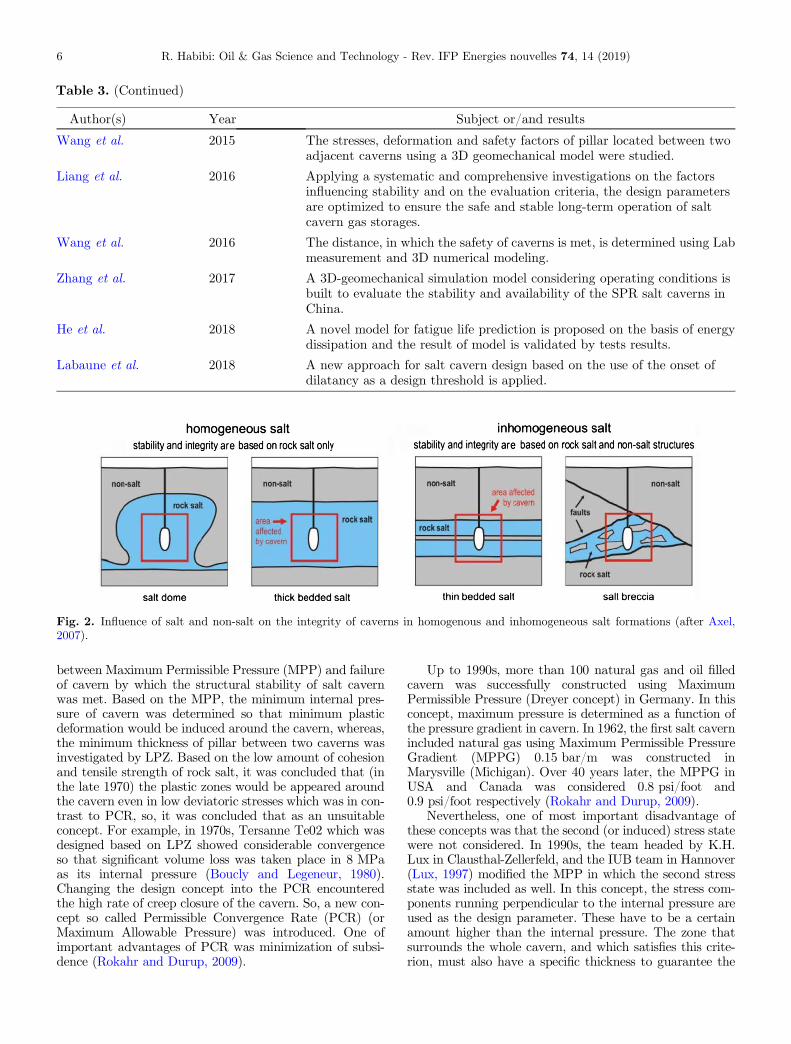
Rock salt in almost homogeneous salt formation creeps ingeological time scale from which principal stress becomesHydrostatic. At such the salt mass stress redistributionand resulting in the induced deformation around caverntends to be uniform by which long term and stability ofthe cavern is satisfied. In contrast, in some areas (particu-larly in bedded salt formation) rock salt and non-salt rock’sdeformation would be non-uniform (Fig. 2). In addition, theintegrity of caverns constructed in inhomogeneous salt struc-tures no longer solely relies on the quality of the surroundingsalt: they also have to rely on the interaction between differ-ent geological formations (Axel, 2007). As tightness is adecisive factor for storing in salt caverns, researchers focuson the tightness properties of the caverns to check theirfeasibility for storing different media. Then, creep closureof salt cavern is one of most considerable issue in cavern sta-bility and tightness which depends on geo-mechanical char-acteristics of rock salt and stress state around cavern.In some areas where the rock salt is thick, the deformablebehavior of salt resulting from k = 1 (a ratio between hori-zontal and vertical geostatic pressure), as the stress state ismore or low monotonic, by increasing time rock salt behavessimilar as a Newtonian material. However, in conditionwhere the stress state is not monotonic (i.e. k 5 1), forexample in bedded rock salt with low thickness, the stressstate must be investigated as exactly as possible
R. Habibi: Oil & Gas Science and Technology - Rev. IFP Energies nouvelles 74, 14 (2019) 3

(Heusermann et al., 2003). Also, based on investigation ofuniaxial compression tests, Liu et al. (2016) concludedthat deformation and damage would be occurred differ-ent in rock salt including inclusions. Also, it was deducedthat the reason of longitudinal cracks is because of deforma-tion inconsistency between almost hard mud stone androck salt at such the condition the lateral deformation ofrock salt becomes larger than Cohesion. Otherwise, intriaxial stress states, the difference deformations arelimited such that the longitudinal cracks would not bevisible.
So, the mechanical properties of rock salt vary (eitherbedded or dome) greatly due to differences in the environ-ments where they were formed, sediment components,crystal geometries, content and distribution of impurities,tectonic histories experienced, etc. (Hou, 2003; De Vrieset al., 2005; Liang et al., 2007). Based on various Lab inves-tigations have been performed to understand the behaviorof rock salt, it is concluded that the behavior is very compli-cated which depends on stress amount and history, temper-ature, moisture, etc. But, authors have the same viewpointin following features:
1. Salt behaves like a fluid in the sense that it flows evenunder small deviatoric stress. Salt is a non-Newtonianfluid and its strain rate is proportional to a rather highpower of applied deviatoric stress (which means thatthe creep rate of a cavern is a highly non-linear func-tion of its internal pressure or, more precisely, of thegap between the lithostatic pressure at cavern depthand its internal pressure) (Berest et al., 1998).
2. The strain rate is also strongly influenced by temper-ature; enlarging by one or two orders of magni-tude when the temperature increases by 100 �C,(i.e. 180 �F) (Berest et al., 1998).
3. As increasing the deformation, rock salt dilates.
On the other hand, few well-documented field data areavailable. Some deep natural gas storages have experiencedlarge volume losses; well known cases include the Eminencesalt dome gas storage in Louisiana (Baar, 1977) and theKiel gas cavern in Germany (Kuhne et al., 1973). Severalshut-in tests or brine flow measurements have been per-formed in different sites. The results are, in general, heavilyinfluenced by brine thermal expansion (Berest et al., 1998),where the real effect of creep is hidden by the leading partplayed by brine temperature variations.
3 Design concepts
To answer the question on ‘‘What basis must be designedthe salt cavern?’’, the design concepts would be appeared.Based on Lab and in-situ investigations, various authorshave proposed variant concepts. Some of them such as Lim-ited Plastic Zone (LPZ) and Permissible Convergence Rate(PCR) are based on Lab investigation proposed in early1970 and in the late 1970 respectively (Rokahr and Durup,2009). In 1960s, based on investigation of pillar models,Dreyer proposed a concept by which it could be possibleto determine the minimum internal pressure to stabilizecavern geomechanically. Dreyer introduced a relationship
Design parameters of cavern
GeomatericalHeight, Diameter, Height
diameter ratio, Average depth, Shape
Mechanical
Density, Poisson ratio, Young, Shear and Bulk modules,
Constitutive low parameters, Tensile and compression
strength, Stabilty criterion parameters
ThermalThermal conductivity, Geo-thermal gradient, Thermal
capacity, Thermal diffusivity, Thermal expansion factor
Hydraulic Permeability, Porosity, Effective pressure gradient
OperationOperation program, Injection and production rate, Surface
equipment
Fig. 1. Design parameters of a single cavern located in salt bed or dome.
R. Habibi: Oil & Gas Science and Technology - Rev. IFP Energies nouvelles 74, 14 (2019)4

Table 3. Summary of researches performed in salt cavern stability in last decades.
Author(s) Year Subject or/and results
Albrecht et al. 1980 Stability of cavern including stored material was investigated.
Dreyer 1982 Stability of cavern was investigated and some possible mechanismsincorporated in hydraulic fracturing were discussed.
Hoffman and Ehgartner 1993 A 3D finite element model to investigate the effects of a number of cavernson storage losses, surface subsidence, and cavern integrity have beendeveloped.
Barron 1994 Two of USA’s strategic caverns based on their location, depth, shape,spacing, internal and operation pressure were investigated.
Chan et al. 1996 An investigation into generation and growth crack in rock salt was done.Staudtmeister and Rokahr 1997 Cavern design’s processes were divided in four steps and a design concepts
were approached.
Adams 1997 A guidelines for the gas pressure inside the cavern using a 2D finite elementmodel has been developed. The minimum and maximum gas pressure andthe proper distance between the adjacent caverns were investigated.
De Vries et al. 2002 A continuum damage criteria to determine minimum operational pressurefor caverns located in salt beds was developed.
Heusermann et al. 2003 Methodology of cavern design by using numerical methods was discussed.Bruno et al. 2005 Geo-mechanical analyses to determine operational pressure range for cavern
located in salt beds in USA was investigated.
De Vries et al. 2005 A finite element model to evaluate the effects of the cavern designparameters (roof thickness, depth, and aspect ratio) on the minimumallowable gas pressure of the cavern has been developed.
Sobolik and Ehgartner 2006 Safety factor, volume loss and subsidence resulting from the cylindrical saltcaverns, also caverns with wide part at above, middle and bottom wereinvestigated.
Han et al. 2007 A finite difference model in FLAC3D for a single-bedded salt cavern hasbeen developed.
Ardeshiri & Yazani 2008 The influence of faults on the seismic behavior of the underground cavernsusing the FLAC2D have been studied. A dynamic non-linear analysis wasperformed under an earthquake ground motion at the bottom of the model.
Hilbert & Exponent 2008 The casing failures associated with the caverns in bedded salt domes using afinite element model have been investigated.
Wang et al. 2009 Stability of cavern’s roof was investigated.
Wang et al. 2011 Maximum displacement, plastic deformation and optimized width of thepillars in cylindrical and pear-shaped caverns were investigated.
Ma et al. 2012 The convergence of salt caverns in an ultra-deep formation at hightemperatures using the creep tests have been investigated.
Nazary Moghadam et al. 2013 A Lagrangian finite element formulation of the salt cavern with an elasto-viscoplastic constitutive model for the salt to evaluate the dilatancy andcreep of the cavern in short terms and long terms have been developed.
Wang et al. 2013 Used 3D geomechanical simulation to validate the analytical model ofunderground salt cavern shape optimizing, showing that the newly proposedsalt cavern could achieve greater effective volume and ensure better stabilityduring a long-term creep.
Djizanne et al. 2014 The stability of the overhanging blocks under the debrining and speedy gasproduction was studied in gas storage salt cavern including irregular shapeusing a 2D numerical model.
(Continued on next page)
R. Habibi: Oil & Gas Science and Technology - Rev. IFP Energies nouvelles 74, 14 (2019) 5
between Maximum Permissible Pressure (MPP) and failureof cavern by which the structural stability of salt cavernwas met. Based on the MPP, the minimum internal pres-sure of cavern was determined so that minimum plasticdeformation would be induced around the cavern, whereas,the minimum thickness of pillar between two caverns wasinvestigated by LPZ. Based on the low amount of cohesionand tensile strength of rock salt, it was concluded that (inthe late 1970) the plastic zones would be appeared aroundthe cavern even in low deviatoric stresses which was in con-trast to PCR, so, it was concluded that as an unsuitableconcept. For example, in 1970s, Tersanne Te02 which wasdesigned based on LPZ showed considerable convergenceso that significant volume loss was taken place in 8 MPaas its internal pressure (Boucly and Legeneur, 1980).Changing the design concept into the PCR encounteredthe high rate of creep closure of the cavern. So, a new con-cept so called Permissible Convergence Rate (PCR) (orMaximum Allowable Pressure) was introduced. One ofimportant advantages of PCR was minimization of subsi-dence (Rokahr and Durup, 2009).
Up to 1990s, more than 100 natural gas and oil filledcavern was successfully constructed using MaximumPermissible Pressure (Dreyer concept) in Germany. In thisconcept, maximum pressure is determined as a function ofthe pressure gradient in cavern. In 1962, the first salt cavernincluded natural gas using Maximum Permissible PressureGradient (MPPG) 0.15 bar/m was constructed inMarysville (Michigan). Over 40 years later, the MPPG inUSA and Canada was considered 0.8 psi/foot and0.9 psi/foot respectively (Rokahr and Durup, 2009).
Nevertheless, one of most important disadvantage ofthese concepts was that the second (or induced) stress statewere not considered. In 1990s, the team headed by K.H.Lux in Clausthal-Zellerfeld, and the IUB team in Hannover(Lux, 1997) modified the MPP in which the second stressstate was included as well. In this concept, the stress com-ponents running perpendicular to the internal pressure areused as the design parameter. These have to be a certainamount higher than the internal pressure. The zone thatsurrounds the whole cavern, and which satisfies this crite-rion, must also have a specific thickness to guarantee the
Table 3. (Continued)
Author(s) Year Subject or/and results
Wang et al. 2015 The stresses, deformation and safety factors of pillar located between twoadjacent caverns using a 3D geomechanical model were studied.
Liang et al. 2016 Applying a systematic and comprehensive investigations on the factorsinfluencing stability and on the evaluation criteria, the design parametersare optimized to ensure the safe and stable long-term operation of saltcavern gas storages.
Wang et al. 2016 The distance, in which the safety of caverns is met, is determined using Labmeasurement and 3D numerical modeling.
Zhang et al. 2017 A 3D-geomechanical simulation model considering operating conditions isbuilt to evaluate the stability and availability of the SPR salt caverns inChina.
He et al. 2018 A novel model for fatigue life prediction is proposed on the basis of energydissipation and the result of model is validated by tests results.
Labaune et al. 2018 A new approach for salt cavern design based on the use of the onset ofdilatancy as a design threshold is applied.
Fig. 2. Influence of salt and non-salt on the integrity of caverns in homogenous and inhomogeneous salt formations (after Axel,2007).
R. Habibi: Oil & Gas Science and Technology - Rev. IFP Energies nouvelles 74, 14 (2019)6

integrity of the cavern. Figure 3 shows the development ofDesign Concepts in historical view.
4 Design methods
To answer the question ‘‘How would appear the conceptparameter in deformation process of salt cavern based onthe initial and boundary condition?’’, the stability criterionis utilized (Sect. 5), but, in order to make a relationshipbetween concept parameter and stability criterion, it mustbe applied the Design Methods. Various methods have beenproposed by authors (Fig. 4). Earlier, experimental meth-ods were applied but they were unable to consider allparameters and characteristics included in integrity andstability of cavern. On other hand, Analytical Methods,because of their complexity, only have been applied incaverns including simple geometry. In last decades, someof salt’s characteristics such as damage onset and dilationstrength have been defined based on Continuum DamageMechanics (CDM), nonetheless, the behavior of salt hadbeen considered in Continuum Mechanics (CM). It isassumed in CM, salt has no micro-crack and behaves ductilein which volume changes during creep deformation and fail-ure resulting from macroscopic creep rupture. Based on Laband in-situ investigations, attitude on behavior of rock salthas been changed, authors concluded that as loading rateand stress intensity reaching a certain level, mainly inter-crystalline micro-fractures open; with increasing stress ordeformation the micro-fractures grow and connect as well.Nevertheless, the CM is not suitable to describe such thebehavior of rock salt. Based on the Lab investigation,
dilation increases the permeability, it means that themechanical damage affects on hydraulic behavior of rocksalt. On other hand, temperature and pressure of storedmaterial change (as a part of thermo-dynamical behaviorof stored material) during injection and production. Theknowledge of the Thermo-Hydro-Mechanical (THM) mate-rial behavior of the in-situ rock salt is a main assumption toproof the static stability and tightness of salt which notconsidered in earlier methods. Nowadays very complexnumerical codes, such as LOCAS (Brouard Consulting,2014) and enhanced material models, such as Lux/Wolters(Wolters et al., 2012), are used to simulate the behavior ofsalt caverns by which the thermal, hydraulic, thermo-dynamical, and geomechanical history of the cavern aremodeled simultaneously.
5 Development of stability criteria
Salt caverns progressively close because salt deforms contin-uously (creeps) when subjected to shear stress resulting fromthe difference between the cavern pressure acting on thewalls of the cavern and the in situ stress in the surroundingsalt. The shear stresses increase as the cavern pressuredecreases. In turn, the rate of creep closure increases nonlin-early as a power function of the shear stress. Creep deforma-tion alone is a constant volume process in salt. However, ifthe pressure in a cavern is decreased too far, the shearstresses in the surrounding salt can exceed the strength ofthe salt. The salt then will microfracture or dilate, creatingadditional porosity in the salt, and its volume will increaseduring creep deformation. Microfracturing, which is referred
Fig. 3. Design Concepts
Fig. 4. Design Methods (Asgari and Brouard, 2014)
R. Habibi: Oil & Gas Science and Technology - Rev. IFP Energies nouvelles 74, 14 (2019) 7

to as damage, causes the creep rate of salt to increasebecause the salt is weakened and its resistance to shearstress is reduced. In some cases, salt caverns are designedfor seasonal operation scenario, nonetheless, in other cases,politics and demands cause the cavern to be designed forweekly, daily and even hourly operation scenario. So, a sys-tematic and comprehensive stability and evaluation criteriaincluding influencing factors that are relevant during theshort and long-term operation of underground salt caverngas storages is required.
High deliverability of salt cavern are controlled byfollowing geotechnical and operational constraint:
1. Operational constraint: wellbore performance (gaspressure loss), production tubing erosion and noising,cavern performance (cavern pressure/temperaturedrop), Hydrate formation at wellhead (low with-drawal temperature) (Karimi-Jafari et al., 2011).If the temperature of gas is enough low, hydrate for-mation would be appeared in pipes. Temperature levelfor Hydrate formation depends on gas pressure andwater content. Sometimes, before gas withdrawal,gas hydrate inhibitors are injected into the well.
2. Geotechnical constraint: injection and withdrawncause temperature changes resulting in thermal stres-ses on wall, in turn, it causes microfracturing anddamage. On other hand, in fast cycles, the rate of pres-sure changes are high, with considering the fatiguebehavior of salt and time-dependent behavior of stressredistribution, mechanical problems would beappeared (Karimi-Jafari et al., 2011).
Similar to the creep, damage is also a progressive processto overcome the shear strength by resulting from shearstress. So, at such the condition, induced stress in long termor cyclic operation (resulting from injection and withdrawn)causes microfracturing at which salt facing to flake andcollapse at wall and roof of cavern respectively. So, it mustbe applied a comprehensive stability criterion to describethe behavior of salt in different conditions.
5.1 Stability analysis criteria
These criteria are applied to investigate the integrity andstability of caverns based on stability parameter which, inturn, corresponding to design concept. It is comprised in6 groups:
1. No or low dilatant zone: as dilation occurs in rock saltresulting in strength loss at such the condition suspectthat introduced shear stress cause failure (Brouardet al., 2007).
2. No or low tensile zone: generally, cavern is subjectedin compression, but when the cavern pressure is lowand cavern profile including no non-convex portions,tensile zones are introduced in which lead to roofand wall spalling (Karimi-Jafari et al., 2011).
3. No or low tensile effective stress (Brouard et al.,2007).
4. Low volume loss or low volume loss rate (Brouardet al., 2007).
5. Subsidence (Brouard et al., 2007).6. Strain – Creep, accumulated strain must not be larger
than a certain amount. In pillar of salt mines, 5%–10%of creep strain is common (Karimi-Jafari et al., 2011).
No or low dilatant zone: as dilation occurs in rock saltresulting in strength loss at such the condition suspect thatintroduced shear stress cause failure (Brouard et al., 2007).
No or low tensile zone: generally, cavern is subjected incompression, but when the cavern pressure is low andcavern profile including no non-convex portions, tensilezones are introduced in which lead to roof and wall spalling(Karimi-Jafari et al., 2011).
No or low tensile effective stress (Brouard et al., 2007).Low volume loss or low volume loss rate (Brouard et al.,
2007).Subsidence (Brouard et al., 2007).Strain – Creep, accumulated strain must not be larger
than a certain amount. In pillar of salt mines, 5%–10% ofcreep strain is common (Karimi-Jafari et al., 2011).
On one hand, the Low volume loss and Subsidence arealmost same which have low applicability. On other hand,the 4th, 5th and 6th have not been applied in engineeringworks. So in following, we only focus on the others.
5.1.1 No or low tensile zone
Generally, the tensile strength of rock salt (1.5–2 MPa) islow and behaves brittle in tension states. So, it must beneglected in designing. Karimi-Jafari et al. (2011) con-cluded that roof collapses are common at tension state.Various factors such as over-pressuring, thermal shocksresulting from fast cold during withdrawn and existenceof an extended roof, cause tensile stress around caverns.Large tensile stresses cause the cracks to be generated inwhich resulting in fracturing and spalling on wall and roof.In general, stresses around cavern are compressive, but infollowing cases, the tensile stress would be appeared aroundcavern:
When cavern pressure is low and cavern’s profile includ-ing no non-convex portions (An example of this is describedin Nieland and Ratigan, 2006).
When cavern pressure suddenly decreased (pressure losscause the temperature of gas to be decreased), temperatureloss depends on production rate, size and shape of cavern.Tensile stresses resulting from temperature loss. As tensilestress is larger than the difference between geostatic andcavern pressure, the microcracks are generated (more detailare discussed in: Bauer and Sobolik, 2009; Staudtmeisterand Zapf, 2010; Karimi-Jafari et al., 2011; Rokahr et al.,2011; Berest et al., 2012; Leuger et al., 2012; Lux andDresen, 2012).
In most cases, depth of these microcracks are low andperpendicular to cavern wall. As the depth of the cracksbecomes larger, distance between two cracks becomes largeras well, in which resulting in slabs of rock salt cut off fromcavern wall. Nevertheless, these slabs are clung on rock salt,
R. Habibi: Oil & Gas Science and Technology - Rev. IFP Energies nouvelles 74, 14 (2019)8
as the depths are low (Berest et al., 2012; Pellizzaro et al.,2011).
In mine’s wells, thermal fracturing are common inunlined wells (Wallner and Eickemeier, 2001; Zapf et al.,2012). Since, wells are cold in winters, at least experiencethis condition for months, and normal stress on wall islow compressive than geostatic stress, in most cases, frac-turing is occurred horizontally.
5.1.2 No or low effective tensile stress
Effective tensile stress relates with porosity of the rock, it isapplies progressively at reservoir engineering. It equalsactual stress (the compressive is negative) plus fluid pres-sure in pores. Since porosity and permeability of rock saltare low, defining the effective stress in rock salt is still com-plex and challengeable, nevertheless, it is defined easily atcavern wall as sum of actual stress and cavern (fluid) pres-sure (Brouard et al., 2007). Actual stress at cavern wallincluding normal stress, tangential stress and circumferen-tial stress. Based on the definition, since the normal stressequals cavern pressure, then, the effective stress is zero.Nevertheless, on such condition that cavern experiences,effective stresses could be negative (tensile) or positive(compressive). Some of authors believe that the effectivestress at cavern wall must be smaller than a certain amountso called Tensile Strength. So, the no or low Effective StressZone is defined:
rmin þ P < T ð1Þ
where T, tensile strength, P, cavern pressure and rmin issmallest tangential compressive stress. According to equa-tion (1), when cavern experience large and fast cycles,developing the effective tensile stress are possible. So, saltcaverns including natural gas which experience largecycles, developing these zones are easily occurred.Microcracking is initiated when the equation (1) is met,resulting in the permeability increase and salt softens(Berest et al., 2001; Malinsky, 2001; Stormont, 2001).Selecting T = 0 (because of safety), definition of criterionwould be simple in which the tensile effective stress mustnot be appeared.
Brouard et al. (2007) studied the effect of fast pressureincrease at caverns which experience actual operationalcycles on stability of caverns. They took three constitutivemodels for a cavern located at 1500 m depth. The resultsshowed that such pressure changes introduce effectivetensile stress at cavern wall, in which, the dependence ofeffective tensile stress on the number of cycles is moresensitive than on pressure change rate at which, as thenumber of cycles is increasing, the effective tensile zone isincreasing as well. Also, they investigated developing ofeffective tensile stress possibility in caverns which subjectedto high pressure changes such as natural gas’s caverns, itwas concluded that the possibility is high at cavern wallbecause of high pressure changes. It causes redistributionstress around cavern when cavern pressure is low enoughin which the deviatoric stress slowly increase resulting inthe difference between tangential and radial stress decrease.At end of the period, when gas is injected into cavern, large
elastic stresses are introduced at cavern wall, in turn, result-ing in the tangential stress to be larger than normal stress.Such that condition, the effective tensile stress at cavernwall would be generated. Nevertheless, Brouard et al.(2007) studied conservatively, tensile strength assumed zeroand fluid pressure in rack mass considered equal cavernpressure.
Djizanne et al. (2012) discussed the criterion of EffectiveTensile Stress. They investigated the effective tensile zonesin Etzel K-102 at Germany which has been operated for20 years. Based on their results, effective tensile stress isgenerated when rapid increase or decrease pressure isoccurred. Also, during fast pressure loss in cavern includinggas or fast pressure increase in brine-filled cavern, effectivetensile zones are appeared, in which microcracking is initi-ated and, in turn, causes permeability increase. The zoneswould be larger, when cavern subjected to very fast pressurechanges in which it was idle before this pressure changes.In some cases, it is not thickness. Nevertheless, the integrityof cavern is treated considerably when the distance betweentop of the salt formation and roof is low. Accordance tothese results, the effective tensile stress is considered atinterpretation of hydraulic fracturing.
5.1.3 Dilation boundary criteria
A dilatancy boundary models could be able to determinethe dilatant behavior of salt around the salt cavities, toachieve which it must be determined the stress state usingClosed Form Methods (CFM), Finite Element Methods(FEM), Difference Element Methods (DEM), etc.Dilatancy surfaces (which have damaged resulting fromonset of volumetric dilation under loading) have beenextensively studied. Some of Dilatancy boundary modelshave been proposed in recent years (e.g. Spiers et al.,1988; Ratigan et al., 1991; Stormont et al., 1992; Hunsche,1993; Thorel et al., 1996; Hatzor and Heyman, 1997).
Dilatancy boundary models have been proposed in twoformat: 1) including stress invariant with experimental fit-ting parameters (invariant or damage-based), 2) includingminimum principal stress and effective stress (stress-based).Dilatancy models have been applied extensively to distin-guish such a condition in which accumulated damage atcavern could be appeared (Van Sambeek et al., 1993;Chabannes et al., 1999; Thoms et al., 1999; Ehgartnerand Sobolik, 2002; Nieland et al., 2001).
5.1.3.1 Stress-based dilatant boundary criteriaThese criteria make a linear or non-linear dilatancy bound-ary dividing two parts so that above the boundary, dilatantwould be occurred. Models developed in stress concept arelisted in Table 4. Also, Figure 5 shows the relationshipresulting from these criteria as a comparison. Based onDe Vries et al. (2002), it could be concluded that the dila-tancy-based criteria enable to estimate the dilatancyboundary of rock salt more exactly with respect to stress-based criteria. The lower minimum gas pressure deter-mined using the damage-based criterion is possible as well.
The working gas capacities of the caverns are directlyproportional to the volume of the caverns. Cavern volume
R. Habibi: Oil & Gas Science and Technology - Rev. IFP Energies nouvelles 74, 14 (2019) 9

is reduced by creep closure. The creep closure rate of thecavern is inversely proportional to the minimum gas pres-sure and is highly nonlinear. The damage-based approach
predicts lower allowable minimum gas pressures than thosepredicted by the conventional stress-based criterion. Thelower minimum gas pressures predicted using the damage-based criterion could increase the initial working gas capac-ity of the existing cavern (Fig. 6). For example, De Vrieset al. (2003) in Bay Gas Well No. 1 and 2 showed thatthe lower minimum gas pressures predicted using the dam-age-based criterion could increase the initial working gascapacity of the existing cavern by about 18 percent andthe cavern under development by about 8%.
5.1.3.2 Damage-based dilatant boundary criteriaDilatancy- based criteria have been developed on Contin-uum Damage Approach and damage potential parameter.Damage potential is defined as a ratio between stress invari-ants (
ffiffiffiffiffi
J 2p
=I1, where J2, second invariant of deviatoricstress and, I1, first invariant of stress), so, these criteriaare also defined as a function of stress invariant either inter-cept or not. Nevertheless, effects of loading history are notconsidered in this model, De Vries et al. (2002) showed thatthe minimum allowable gas pressure (which controls theamount of working gas) for gas-filled caverns is lower whendamage-based criteria are applied, however, the stress-based criteria overestimate the minimum allowable gaspressure. Figure 6 shows stress invariant-based criteria withrespect to damage-based criteria. In the following, thesecriteria are briefly discussed. Also, Figures 7 and 8 give acomparison of damage-based criteria in respect of eachother.
Table 4. Stress-based Dilatancy boundary models.
Model Author(s) Description
CDM Hampel (2012) In high stress differences of boundary, damage and dilatantchanges are modeled as a function of creep strain. This modelenables to consider effects of common and reverse transientcreep (Hampel, 2012).
Gunther and Salzer Gunther and Salzer, 2007 This is a strain hardening model in which total deformationrate is a function of effective strain hardening (Gunther andSalzer, 2007).
Minkley andMuhlbauer
Minkley and Muhlbauer, 2007 In this model, stress-strain relationship is modeled by adeveloped Burgers model in which deformation history isconsidered through a state variable. Also, this model includesa damage module to consider the damage changes, fractureand post failure (Minkley and Muhlbauer, 2007).
KIT Pudewills, 2007 This model applies elasto-visco-Plastic context to describe thetotal deformation rate (Pudewills, 2007).
Lubby2-MDCF Institut fur Unterirdisches Bauen,IUB
In this model, total inelastic deformation rate in non-dilatantcreep and dilatant creep are described by shear deformationand tensile deformation respectively (IUB).
Hou and Lux Hou and Lux, 1999 In this model, inelastic strain rate is considered throughadaption of visco-plastic deformation in creep without volumechanges, damage and healing resulting from dilatancy andcompression respectively (Hou and Lux, 1999).
Fig. 5. Different dilatant boundary criterion developed throughminimum principal stress and effective stress TC: triaxialcompression, TE: triaxial extension (after Hampel et al., 2012).
R. Habibi: Oil & Gas Science and Technology - Rev. IFP Energies nouvelles 74, 14 (2019)10

5.1.3.2.1 Spiers et al.Spiers et al. (1988) used the results of constant strain ratetests that had been performed on samples which obtainedfrom Asse salt mine in Germany, a dilatancy criterionproposed:
Dr ¼ 2:74P þ 6:4 ð2Þ
In stress invariant, are given:
ffiffiffiffiffi
J 2
p¼ 0:27I1 þ 1:9 ð3Þ
where P, confining pressure, Dr, difference between axialstress and confining pressure in MPa. Equation (2) is alinear function aspect toI 1 and J 2, it means, the damageis linear as well. However, based on lab and in-siteinvestigation, damage is non-linear function in stressspace. One important shortcoming is, the tests only basedon cylindrical samples which conducted in triaxialcompression state, despite, cavern experiences tensilestate especially at roof. Also, stress path and history notconsidered.
5.1.3.2.2 Ratigan et al.Based on the damage potential of WIPP rock salt, Ratiganet al. (1991) developed a dilatancy criterion. This criterionis based on the results of volumetric strain rate changes of
WIPP and Avery Island in Louisiana, and also, oncreep tests had been performed in room temperature. Thenegative volumetric strain rate was defined as ‘‘non-dilatanting’’ and vice versa. Based on this definition, follow-ing criterion was proposed to distinguish the dilatancyboundary:
ffiffiffiffiffi
J 2
p¼ 0:27I1 ð4Þ
In fact, this is highly similar to that of Spiers et al.(1988). In this criterion, not only stress path and historynot considered, also the intercept was neglected.
5.1.3.2.3 HunscheBased on 14 triaxial tests performed on cubic sample thathad been obtained Asse salt mine, Hunsche (1993) proposeda compressibility/dilatancy boundary criterion (Hunschenotified that sample shows either volume increase or volumedecrease, then, a compressibility/dilatancy term wasapplied). The boundary is determined by volumetric strainsand acoustic emission rates:
soct ¼ f1r2m þ f2rm ð5Þ
Fig. 7. Comparison salt dilation boundaries of differentresearch organizations (after De Vries et al., 2005).
Fig. 6. Comparison stress-based against damage-based criteria(after De Vries et al., 2003).
R. Habibi: Oil & Gas Science and Technology - Rev. IFP Energies nouvelles 74, 14 (2019) 11

In stress invariant, are given:
ffiffiffiffiffi
J 2
p¼
ffiffiffi
32
r
f1I21
9þ f2
I1
3
� �
ð6Þ
where soct, octahedral shear stress and rm, octahedral nor-mal stress or mean stress. f1, f2 are constant,�0.0168 MPa�1 and 0.86 respectively. This criterion isalso based on triaxial compression tests and no considera-tion for stress path and history.
5.1.3.2.4 Hatzor and HeymanUsing by results of constant strain rate that had beenperformed on cylindrical samples obtained Mount SedomDiaper in Israel, Hatzor and Heyman (1997) proposed adilatancy criterion. Salt formation in this area is layer whichis almost perpendicular near to ground level and as depthincrease, the slope is decrease. So, they consider the layerorientation in the criterion. Based on the results, it isdemonstrated when maximum compressive principal stressis applied perpendicular to bedding plane orientation,strength of rock salt decrease. Then, the criterion was devel-oped based on principal stresses and bedding orienta-tion (b). The empirical model to consider compressibility/dilatancy of anisotropic rock salts are given:
r1 ¼ k1ek2b ð7Þ
k1 � 0:0743r32 þ 3:2223r3 þ 12:9 ð8Þ
where k1 is a function of minimum principal stress, k2, is aconstant, �0.0057 which is determined from regressionanalysis with the constant k1 by second equation. Sincethis formulation is for an anisotropic material, isotropyin stress space is lost and their equation cannot be castin terms of the stress invariants and compared with theother dilation criteria presented here.
5.1.3.2.5 De Vries et al.During a project on samples obtained Cayuta of USA whichsponsored by RESPEC, De Vries et al. (2005) developed
a comprehensive dilation criterion. It is based on Mohr-Coulomb dilatant which applied to evaluate potential pfmicrocracking in cavern using Damage Potential (DP).Shortcomings identified for the DP criterion are that thiscriterion does not include: 1) no nonzero intercept, 2) nononlinear relationship for dilatancy boundary in I1 �
ffiffiffiffiffi
J 2p
space, 3) no cover effects of Lode angle. The old damage-based dilation boundary criteria such as Mohr–Coulombwere not considered the effects of Lode angle changes,resulting in no consideration for mean stress changes(Fig. 9). However, De Vries et al. (2005) covered theseshortcoming and proposed a comprehensive dilationcriterion:
ffiffiffiffiffi
J 2
p¼
D1I1
sgn I1ð Þr0
� �nþ T 0
ffiffiffi
3p
cos w� D2 sin w� � ð9Þ
where n is a power less than or equal to one and r0 is adimensional constant with the same units as I 1. D1;D2
are material constant. T 0;w are tensile strength and Lodeangle respectively.
6 Distance from adjacent cavernand dome edge
The cavern concept and design are single cavern-relatedsubjects, however, the stability must be met in appearanceof cavern group located either salt layer or salt dome.So, two subject including distance between two adjacentcaverns (pillar) and distance from roof and/or dome edgewould be appeared.
6.1 Pillar stability
How to design the width of pillar is a difficult engineeringproblem, since the pillar width is greatly influenced bymany factors such as strength of rock salt and non-saltformations, rock salt creep characteristics, cavern dimen-sions, etc. The overburden pressures and far field in-situstresses are two major reasons of pillars failure locatedbetween salt caverns. For storage caverns in salt rock, withincreasing deformation, the creep damage zones would beappeared in different places of pillar which trend to linkup with each other. Considering narrow pillar, the creepdamage zones easily merge and cracks develop in the pillarwhich threat the tightness or stability.
In last decades, various pillar design methods and stabil-ity criteria have been proposed which comprise three maingroups including: analytical (such as cusp catastrophetheory), experimental (such as Van Sambeek, 1997) andnumerical. Earlier, the pillar (between two adjacentcaverns) was considered as engineering problem at saltcaverns similar to which has been considered in salt mining(rectangular in shape). In 1972, Thom (1972), firstly,proposed the cusp catastrophe theory, which was mainlyused to depict numerous sudden discontinuous changephenomena in nature and predict the critical conditions ofstructure mutations. Even though, researchers could not
Fig. 8. Comparison of damage – based salt dilation boundariesof different authors (after Labaune et al., 2018).
R. Habibi: Oil & Gas Science and Technology - Rev. IFP Energies nouvelles 74, 14 (2019)12

be able to get the differential equations of the system orhow to solve these equations, the qualitative or quantitativestate of the system can be predicted by it (as an advantageof cusp catastrophe theory). This theory, successfully, hasbeen applied by many authors (Fu and Chen, 2008;Kenneth et al., 2008; Li et al., 2008; Pan et al., 2009;Leynaud and Sultan, 2010; Yang et al., 2010) to analysethe stability of nonlinear material structures so that thecorresponding failure mechanisms are revealed. In 90’sdecade, some experimental methods for pillar designingand stabilizing proposed. In 1996, Van Sambeek proposeda new method at which the stress states within the salt pil-lar could be approximate using average vertical stress in thepillar. It was validated by comparing with numerical simu-lation in highly correlation (Frayne and Van Sambeek,2002). Except experimental figures, it was only consideredthe pillar dimensions (height, width and length).Staudtmeister and Rokahr (1997) proposed a guideline fordesigning cavern shape and pillar width. In 1993, consider-ing the pillar as support of cavern roof, Waltham andChorlton (1993) developed a roof and pillar model to eval-uate the deformation within the pillar. Contemporary, in1993 firstly, Hoffman (1993) investigated the effect of pillarwidth on the stability of gas storage caverns in salt domesusing in a 3-D finite element software so called JAC3D.These days, numerical simulations are widely-used byauthors to investigate the stability of pillars. Zhao et al.(2002) applied SR FEM to overcome the local failure ofstructures (which takes place in numerical simulation), bywhich the overall stability factors of structures as well asthe detailed information of each node (e.g. stress, strain,and deformation) were given. However, taking into accountthe irregular shapes of actual salt caverns and materialproperties difference, may cause stresses and deformations,at some Gaussian points, to reach the yielding strengthquickly during pillar stability evaluation by SR FEM
(Wang et al., 2015) resulting in the divergence of numericalsimulations and imprecise results. In order to overcome theshortages, De Vries et al. (2005), based on their engineeringexperience, suggested that the salt cavern gas storagescould be considered in critical failure state during numericalsimulations, when the plastic zone area achieved 40 m2.
6.2 Edge stability
Analysing the distance from edge, firstly, was considered insalt mining to determine the boundary of safe deformationin the roof protection shelf. Sałustowicz et al. (1963) consid-ered the dependence of the bending of an elastic beamloaded with mass forces, however, they considered not therheological viscous properties of rock salt. Kortas (1979)claimed that the tensile strain of the roof is the major reasonwhich makes instability near non-salt materials, based onthis theory, he studied the catastrophic inrush of water intothe underground Wapno salt mine (Poland) in 1977.
In current practice of cavern dimensioning, so far, noconcept was published how a gas storage cavern shouldbe dimensioned in the salt dome edge region and whatdistance should a cavern have from the salt dome boundary(Zapf, 2014). In rock mechanics point of view for gas storagecaverns it is, for example, recommended to follow a safetydistance between the caverns. Based on a role of thumbwhich developed using a concept, so called central pillarregion, it must be considered an area in which the stressstate of the rock salt during the entire operating history isbelow the dilatancy limit, which should be remained at leastwith a horizontal dimension of 1.8–2.2 times of the averagediameter of two neighbour caverns (Zapf, 2014). On otherhand, some general rock mechanical investigations concern-ing caverns in the salt dome edge region had been carriedout, for example, by Gehle and Thoms (1983) and Michaelet al. (2002) who proposed some guidance on the influencesof layering on roof deformation and stability within theinterfaces considering maximum tensile and shear stresscomponents of a simple composite beam theory. Neverthe-less, because of complexity of analytical solutions in roofbeams of greater complexity than a couple layers, as wellas, other influences, the equations can only be used to com-pare the relative stresses and fracture risks developed foralternative composite roof configurations.
Additionally, in last decades some regulations (in pointof view of general mining) such as ABVO, in Germany(1966), have been developed which considers an empiricalvalue for the distance between salt mines and salt borders.Based on it, if the geological profile can clearly be deter-mined, it must be considered at least 150 m from the saltedges. However, because these values probably originatedfrom the intention to avoid possible water ingress in saltmines, cannot be helpful these days. (Zapf, 2014). Whilethe ABVO is valid for the building of salt mines, the miningregulation for deep drillings, underground storage buildingsand the extraction of mineral resources, BVOT (2006), con-tains regulations for the construction of caverns in rock saltin which only some advices are given, for instance, cavernshave to be built stable and enough salt should be remainedbetween the cavity and the salt edges. The values given inthe ABVO are not given in the BVOT (Zapf, 2014).
Fig. 9. Illustration of the original stress-based dilation criterionand the new Mohr-Coulomb criterion plotted in principal stressspace (after De Vries et al., 2005).
R. Habibi: Oil & Gas Science and Technology - Rev. IFP Energies nouvelles 74, 14 (2019) 13

On other hand, several organizations have developed guid-ance documents for designing and operating storage saltcaverns such as CSA (1993), API (1994), IOGCC (1995).Some parts of these efforts, however, have focused on someof the critical technical aspects related to cavern develop-ment in thin, heterogeneous, bedded salt formations. Zapfand Staudtmeister (2009) proposed some rock mechanicalaspects for the design of gas caverns in the border regionof salt domes. Vining and Buchholz (2013) addressed thelimitations of the numerical software and the impact thatin situ stress, material properties, and constitutive modelshave on the predicted solution. However, Zapf (2014),created a numerical model that takes into account theessential and non-negligible influences in the salt dome edgearea and time-dependent, thermo-mechanical coupled cal-culations, introduced a recommendation for the selectionof a suitable calculation model of a cavern in the borderregion of a salt dome using numerical modeling.
So, based on the above-mentioned techniques, it couldbe summarized the methods in four major groups including:empirical, analytical, regulations and numerical modeling.
7 Conclusion
Mechanical, thermal and Hydraulic parameters of eitherrock salt or overburden control the short and/or long termbehavior of the salt cavern. So, design and construction ofsalt caverns are so complex. Various design concepts havebeen proposed by authors among them Lux (1997), becauseof considering induced stresses, is more suitable. Also,various stability criteria have been proposed at which a cer-tain parameter to considering salt behavior at different stressstates are applied. Effective Tensile Stress, because of diffi-culty in effective definition in rock salt, unable to describesalt behavior in operation especially at very fast cycles. Sinceat only certain condition, cavern experience tension state, so,no or low tensile zone is not applicable in stability analysis aswell. Nevertheless, in above mentioned two criteria, allparameters which must be interfered in stability of cavernare not considered. However, damage-based dilatant criteria,including stress states, propose suitable response in respect ofothers. For example, they estimate the minimum allowablegas pressure accurately which controls the working gascapacity. The criterion so called RD proposed by De Vrieset al. (2005), not only considers the stress state, but alsoconsiders the effect of Lode angle as well. In general, forassurance, it must be accommodated the results of the crite-rion with in-situ results. Considering a group of cavernslocated in salt dome, by now, expect numerical modeling,no practical method has not been proposed to take intoaccount pillar stability and safe distance from dome edge.
References
Adams J. (1997) Natural gas salt cavern storage operatingpressure determination, Technical Meeting/PetroleumConference of the South Saskatchewan Section, Regina,Saskatchewan, 19–22 October, pp. 1–15.
Albrecht H., Meister D., Storck G.H., Wallner M. (1980) ZurFrage des Standsicherheitsnachweises von Hohlraumen inSalzgetseinen, Proceedings of the 5th International Symposiumon Salt, Hamburg, Germany, May 29–June 1, pp. 195–211(in Deutsch).
Allgemeine Bergverordnung fur Untertagebetriebe, Tagebaueund Salinen (ABVO) (1966) vom 2, Februar. (Nds. MBI. Nr.15/1966 S.337) (in Deutsch).
API (1994) Design of solution-mined underground storagepractices, API Recommended Practice 1114, AmericanPetroleum Institute, Washington, DC, June.
Ardeshiri S., Yazani M. (2008) Numerical study of faultgeometrical effects on seismic stability of large undergroundcaverns, 42nd U.S. Rock Mechanics Symposium (USRMS),San Francisco, CA, 29 June–2 July, pp. 1–8.
Asgari A., Brouard B. (2014) better understand the behaviour ofsalt caverns using LOCASbetter understand the behaviour ofsalt caverns using LOCAS, Proc. 1st underground storing of oiland natural gas, University of Tehran, Tehran, Iran, 20–21May.
Aubertin M., Gill D.E., Ladanyi B. (1991) A unified viscoplasticmodel for the inelastic flow of alkali halides, Mech Mater.11, 1, 63–82.
Axel G. (2007) Natural Gas Storage in Salt Caverns -PresentStatus, Developments and Future Trends in Europe, Pro-ceedings of the SMRI Spring Meeting, Spring 2007 Confer-ence, Basel, Switzerland, 29 April–2 May.
Baar C.A. (1977) Applied Salt-Rock Mechanic. Developments inGeotechnical Eng. 16-A, Elsevier.
Barron T.F. (1994) Regulatory, technical pressures promptmore U.S. salt-cavern gas storage, Oil Gas J. (OGJ Special),92, 37, 55–67.
Bauer S., Sobolik S. (2009) Pressure cycling in compressed airand natural gas storage in salt: Tracking stress states andcavern closure using 3-D Finite Element Code. SMRI SpringMeeting, Krakow, Poland, p. 129.
Berest P., Brouard B., Dump G. (1998) Behaviour of Sealedsolution-mined caverns, Proc. 4th Conf. Beh. Of Salt, Aubertinand Hardy ed., Trans Tech Pub., Clausthal-Zellerfeld,pp. 511–524.
Berest P., Brouard B., de Greef V. (2001) Salt permeabilitytesting, SMRI Research Project No. 2001 1.
Berest P., Brouard B., Feuga B., Karimi-Jafari M. (2008) The1873 collapse of the Saint-Maximilien panel at the Varangevillesalt mine, Int. J. Rock Mech. Min. Sci. 45, 7, 1025–1043.
Berest P., Djizanne H., Brouard B., Hevin G. (2012) Rapiddepressurizations: Can they lead to irreversible damage?Proceedings of the SMRI Spring Meeting, Regina, pp. 63–86.
Boucly Ph., Legeneur J. (1980) Hydrocarbon storage in cavitiesleached out of salt formations, Proceedings of SubsurfaceSpace, Rockstore 80, 1, p. 255.
Brouard Consulting (2014) LOCAS software, http://www.brouard-consulting.com.
Brouard B., Berest P., Karimi-Jafari M. (2007) onset of tensileeffective stresses in gas storage caverns, Solution MiningResearch Institute, Fall 2007 Technical Meeting, Halifax,Canada, October 8–10.
Bruno M., Dorfmann L., Han G., Lao K., Young J. (2005) 3Dgeomechanical analysis of multiple caverns in bedded salt.Proceedings of the Fall Technical Meeting, Solution MiningResearch Institute, Nancy, French.
BVOT (2006) Bergverordnung fur Tiefbohrungen, Untergrund-speicher und fur die Gewinnung von Bodenschatzen durch
R. Habibi: Oil & Gas Science and Technology - Rev. IFP Energies nouvelles 74, 14 (2019)14
Bohrungen im Land Niedersachsen (Tiefbohrverordnung–BVOT-), 9, 20 (in Deutsch).
Cai M., Kaiser P.K., Morioka H., Minami M., Maejima T.,Tasaka Y. (2007) FLAC/PFC coupled numerical simulationof A Enlargescale underground excavations, Int. J. RockMech. Min. Sci. 44, 4, 550–564.
Chabannes C.C., Durup J.G., Lanham P. (1999) GeomechanicalEvaluation of Sabine Gas Transmission Company’s CavernNo. 2 at Spindel Top Salt Dome, Solution Mining ResearchInstitute Spring Meeting, Las Vegas, NV, April 11–14.
Chan K.S., Munson D.E., Bodner S.R., Fossum A.F. (1996)Cleavage and creep fracture of rock salt, Acta Mater. 44,3553–3565.
Cristescu N. (1993) A general constitutive equation fortransientand stationary creep of rock salt, Int. J. Rock Mech.Min. Sci. Geomech. Abstr. 30, 2, 125–140.
CSA – Canadian Standards Association (1993) Storage ofHydrocarbons in Underground Formations – Oil and GasIndustry Systems and Materials, Standard Z341-93, CanadianStandards Association, Rexdale, Ontario, Canada, July.
Cundall P.A. (1988) Formulation of a three-dimensional distinctelement model – part I. A scheme to detect and representcontacts in a system composed of many polyhedral blocks, Int.J. Rock Mech. Min. Sci. 25, 3, 107–116.
De Vries K.L., Mellegard K.D., Callahan G.D. (2002) SaltDamage Criterion: Proof-of-Concept Research, RESPECFinal Report 30 September 2000 – 29 September 2002 forUnited States Department of Energy National Energy Tech-nology Laboratory, Topical Report.
De Vries K.L., Mellegard K.D., Callahan G.D., Goodman W.M.(2005) Cavern roof stability for natural gas storage in beddedsalt, RESPEC final report 26 September 2002 – 31 March 2005for United States Department of Energy National EnergyTechnology Lab.
De Vries K.L., Mellegard K.D., Callahan G.D. (2003) Caverndesign using a salt damage, Solution Mining ResearchInstitute, Spring Meeting, Houston, Texas, USA, 27–30 April.
Djizanne H., Berest P., Brouard B. (2012) Tensile effectivestresses in hydrocarbon storage caverns, Solution MiningResearch Institute Fall 2012 Technical Conference, Bremen,Germany, 1–2 October.
Djizanne H., Berest P., Brouard B. (2014) The mechanicalstability of a salt cavern used for compressed air energystorage (CAES), Proceedings of the 2014 Spring SMRITechnical Conference, San Antonio, Texas, USA, 4–7 May.
Dreyer W. (1982) Underground storage of oil and gas in saltdeposits and other nonhard rocks, Ferdinand Enke Verlag,Stuttgart.
Ehgartner B., Sobolik S. (2002) 3-D Cavern EnlargementAnalyses, Solution Mining Research Institute Spring Meeting,Banff, Alberta, Canada, April 29–May 1.
Frayne M.A., Van Sambeek L.L. (2002) Three-dimensionalverification of salt pillar design equation, in: Cristescu N.D.,Hardy J.R., Simionescu R.O. (eds), Proceedings of the FifthConference on the Mechanical Behaviour of Salt, August 9–11,University of Bucharest, Bucharest, Romania, A. A. Balkema,Netherlands, pp. 405–409.
Fu C.H., Chen S.H. (2008) Study on instability criteria of sur-rounding rock of underground engineering cavern based oncatastrophe theory, Rock Soil Mech. 29, 167–172 (in Chinese).
Gehle R.M., Thoms R.L. (1983) Analysis of a cavern near the flankof a salt dome, Sixth International Symposium on Salt, Vol. I,The Salt Institute Publisher, Toronto, Canada, pp. 545–548.
Gunther R., Salzer K., Popp T. (2010) Advanced strain-hardening approach constitutive model for rock salt describingtransient, stationary, and accelerated creep and dilatancy, 44thUS rock mechanics symposium and 5th US-Canada rockmechanics symposium, American Rock Mechanics Association.
Gunther R.M., Salzer K. (2007) A model for rock salt, describingtransient, stationary, and accelerated creep and dilatancy, in:Wallner M., Lux K.H., Minkley W., Reginald Hardy, Jr. H.(eds), The Mechanical Behaviour of Salt: Understanding ofTHMC Processes in Salt, Taylor and Francis Group, London,pp. 109–117.
Hampel A. (2012) The CDM constitutive model for themechanical behaviour of rock salt: Recent developments andextensions, Proceedings of the 7th Conference on MechanicalBehaviour of Salt, Paris, 16–19 April.
Hampel A., Salzer K., Gunther R.-M., Minkley W., Pudewills A.,Leuger B., Zapf D., Staudtmeister K., Rokahr R., Herchen K.,Wolters R., Lux K.-H. (2012) Joint projects on the compar-ison of constitutive models for the mechanical behaviour ofrock salt. II. Overview of models and results 3D benchmarkcalculations, in: Berest P., Ghoreychi M., Hadj-Hassen F.,Tijani M. (eds), Mechanical Behaviour of Salt VII, Taylor andFrancis Group, London.
Han G., Bruno M.S., Lao K., Young J., Dorfmann L. (2007) Gasstorage and operations in single-bedded salt caverns: Stabilityanalyses, SPE Prod. Oper. 22, 3, 368–376.
Hatzor Y.H., Heyman E.P. (1997) Dilation of Anisotropic RockSalt: Evidence From Mount Sedom Diapir, J. Geophys. Res.102, B7, 14853–14868.
He M., Huang B., Zhu C., Chen Y., Li N. (2018) Energydissipation-based method for fatigue life prediction of rocksalt, Rock Mech. Rock Eng. 51, 1447–1455.
Heusermann S., Rolfs O., Schmidt U. (2003) Nonlinear finite-element analysis of solution mined storage caverns in rock saltusing the LUBBY2 constitutive model Comput. Struct. 81,629–638.
Hilbert L.B., Exponent V.K. (2008) Salt mechanics and casingdeformation in solution-mined gas storage operations, 42ndU.S. Rock Mechanics Symposium (USRMS), San Francisco,CA, 29 June–2 July, pp. 1–12.
Hoffman E.L. (1993) Effects of cavern spacing on the performanceand stability of gas-filled storage caverns, SAND92-2545,Sandia National Laboratories, Albuquerque, NM, US.
Hoffman E.L., Ehgartner B.L. (1993) Evaluating the effects ofnumber of caverns on the performance of underground oilstorage facilities, 34th U.S. Symposium on Rock Mechanics(USRMS), Madison, Wisconsin, 28–30 June, pp. 1–4.
Hou Z. (2003) Mechanical and hydraulic behaviour of rock saltin the excavation disturbed zone around underground facili-ties, Int. J. Rock Mech. Min. Sci. 40, 1, 725–738.
Hou Z., Lux K.-H. (1999) A material model for rock saltincluding structural damages as well as practiceorientedapplications, in: Cristescu N.D., Hardy Jr. H.R., SimionescuR.O. (eds), Basic and Applied Salt Mechanics, Proc. of theFifth Conference on the Mechanical Behaviour of Salt(MECASALT 5), Lisse Swets & Zietlinger (Balkama),Bucharest, pp. 55–59.
Hunsche U.E. (1993) Failure behaviour of rock around under-ground cavities, Proceedings, 7th Symposium on Salt, KyotoInternational Conference Hall, Kyoto, Japan, April 6–9.
IOGCC (1995) Natural Gas Storage in Salt Caverns – A Guidefor State Regulators, Interstate Oil and Gas CompactCommission, Oklahoma City, OK, October.
R. Habibi: Oil & Gas Science and Technology - Rev. IFP Energies nouvelles 74, 14 (2019) 15

Karimi-Jafari M., Gatelier N., Brouard B., Berest P., Djizanne H.(2011) Multi-cycle gas storage in salt caverns, Solution MiningResearch Institute Fall 2011 Technical Conference, York,United Kingdom, 3–4 October.
Kenneth H., John J.C., John F.O. (2008) Legacies of catas-trophic rock slope failures in mountain landscapes, Earth-Sci.Rev. 87, 1–38.
Kortas G. (1979) Ruch gorotworu przed wdarciem sie wod dowyrobisk kopalni soli w Wapnie, Ochrona Terenow Gornic-zych, nr 49. Katowice (in Polish).
Kuhne G., Rohr W.U., Sasse W. (1973) Kiel gas storage facility,tlze first city gas cavern in Germany, Proc. 12th World GasCongress, Nice.
Labaune P., Rouabhi A., Tijani M., Blanco-Martin L., You T.(2018) Dilatancy criteria for salt cavern design: a comparisonbetween stress-and-train-based approaches, Rock Mech. RockEng. 51, 599–611.
Leuger B., Staudtmeister K., Zapf D. (2012) The thermo-mechanical behavior of a gas storage cavern during highfrequency loading, Proceedings, Mechanical Behavior of SaltVII, Taylor & Francis Group, London, pp. 363–369.
Leynaud D., Sultan N. (2010) 3-D slope stability analysis: aprobability approach applied to the nice slope, Marine Geol.269, 89–106.
Li X.B., Zhou Z.L., Lok T.S., et al. (2008) Innovative testingtechnique of rock subjected to coupled static and dynamicloads, Int. J. Rock Mech. Mining Sci. 45, 739–748.
Liang C.G., Huang X., Peng X., Tian Y., Yu Y. (2016)Investigation on the cavity evolution of underground saltcavern gas storages, J. Nat. Gas Sci. Eng. 33, 118–134.
Liang W.G., Yang C.H., Zhao Y.S. (2007) Experimentalinvestigation of mechanical properties of bedded salt rock,Int. J. Rock Mech. Min. Sci. 44, 400–411.
Liu W., Muhammad N., Chen J., Spiers C.J., Peach C.J. (2016)Investigation on the permeability characteristics of beddedsalt rocks, J. Nat. Gas Sci. Eng. 35, 468–482.
Lux K. (1997) Development of a new criterion for the determi-nation of the maximum permissible internal pressure for gasstorage caverns in rock salt, IUB, University of Hanover, SMRI.
Lux K.H., Dresen R. (2012) Design of salt caverns for high fre-quency cycling of storage gas, Proceedings, Mechanical Behav-ior of Salt VII, Taylor & Francis Group, London, pp. 371–380.
Ma H., Yang C., Qi Z., Li Y., Hao R. (2012) Experimental andNumerical analysis of salt cavern convergence in ultra-deepbedded formation, 46th U.S. Rock Mechanics/GeomechanicsSymposium, Chicago, IL, 24–27 June, pp. 1–8.
Malinsky L. (2001) Evaluation of Salt Permeability Tests, SMRIResearch Report, 89 p.
Michael S., Dusseault M., BrunoB. (2002) Geomechanicalanalysis of pressure limits for thin bedded salt caverns,Solution Mining Research Institute, Spring 2002 TechnicalMeeting, Banff, Alberta, Canada, 29–30 April.
Minkley W., Muhlbauer J. (2007) Constitutive models to describethe mechanical behaviour of salt rocks and the imbeddedweakness planes, in: Wallner M., Lux K.-H., Minkley H., Hardy,Jr. R. (eds), Proceedings of the 6th Conference (SaltMech6) TheMechanical Behaviour of Salt – Understanding of THMCProcesses in Salt, Germany, 22–25 May.
Minkley W., Menzel W., Konietzky H., te Kamp L. (2001) Aviscoelasto- plastic model and its application for solving staticand dynamic stability problems in potash mining, Proceedingsof the 2nd international FLAC symposium, Lyon, 29–31October, pp. 21–27.
Munson D.E. (1993) Extension of the M-D model for treatingstress drops in salt, Third Conference on the MechanicalBehaviour of Salt, Ecole Polytechnique, Palaiseau France,pp. 31–44.
Munson D.E., Dawson P.R. (1981) Salt constitutive modelingusing mechanism maps, First Conference on the MechanicalBehaviour of Salt, Pennsylvania State University, pp. 717–737.
Nazary Moghadam S., Mirzabozorg H., Noorzad A. (2013)Modeling time-dependent behaviour of gas caverns in rock saltconsidering creep, dilatancy and failure, Tunn. Undergr.Space Technol. 33, 171–185.
Nieland J.D., Ratigan J.L. (2006) Geomechanical evaluation oftwo gulf coast natural gas storage caverns, Proceedings of theSMRI Spring Meeting, Brussels, pp. 61–89.
Nieland J.D., Mellegard K.D., Schalge R.S., Kaiser H.D. (2001)Storage of Chilled Natural Gas in Bedded Salt StorageCaverns, RSI-1354, prepared by RESPEC, Rapid City, SD,for U.S., Department of Energy, Morgantown, WV, 117 p.
Pan Y.Y., Zhang Y., Wang Z.Q. (2009) Catastrophe theoreticalanalysis of disintegratedoutburst of a single coal shell in coal-gas outburst, Rock Soil Mech. 30, 595–603.
Pellizzaro C., Bergeret G., Leadbetter A., Charnavel Y. (2011)Thermomechanical behaviour of Stublach gas storage caverns.Proceedings of the SMRI Fall Meeting, York, UK, pp. 161–178.
Pudewills A. (2007) Modeling of hydro-mechanical behaviourof rock salt in the near field of repoistory excavtions, Themechanical behaviour of salt: understanding of THMC processesin salt, Talor & Francis Pub Group, London, pp. 195–200.
Ratigan J.L., Van Sambeek L.L., De Vries K.L., Nieland J.D.(1991) The Influence of Seal Design on the Development of theDisturbed Rock Zone in the WIPP Alcove Seal Tests, RSI-0400, prepared by RESPEC Inc., Rapid City, SD, for SandiaNational Lab, Albiquerque, NM.
Rokahr R., Durup G. (2009) Over 40 years of development ofdesign criteria for salt caverns. Solution Mining ResearchInstitute Spring 2009 Technical Conference, Krakow, Poland,27–28 April.
Rokahr R.B., Staudtmeister K., Zapf D. (2011) Rock mechanicaldesign for a planned gas cavern field in the Preesall Projectarea, Lancashire, UK, Proceedings of the SMRI Fall Meeting,York, UK, pp. 190–203.
Sałustowicz A., Dziunikowski J.L., Hwałek S. (1963) Wytrzy-małosc gorotworu przy eksploatacji zło _za solnego komoramipoziomymi i pionowymi, Panstwowa Rada Gornictwa PAN.SITG. Katowice (in Polish).
Sobolik S.R., Ehgartner B.L. (2006) Analysis of shapes for thestrategic petroleum reserve, Sandia National Laboratories,USA.
Spiers C.J., Peach C.J., Brzesowsky R.H., Schutjens P.M.T.M.,Liezenberg J.L., Zwart H.J. (1988) Long term rheological andtransport properties of dry and wet salt rocks, EUR 11848,prepared for Commission of the European Communities, byUniversity of Utrecht, Utrecht, The Netherlands.
Staudtmeister K., Rokahr R.B. (1997) Rock mechanical designof storage caverns for natural gas in rock salt mass, Int. J.Mech. Mining Sci., 34 (3–4), 300–313
Staudtmeister K., Zapf D. (2010) Rock mechanical design of gasstorage caverns for seasonal storage and cyclic operations,Proceedings of the SMRI Spring Meeting, Grand Junction,Colorado, pp. 197–213.
Stormont J. (2001) Evaluation of permeability measurements onspherical salt specimens, SMRI Fall Meeting, Albuquerque,pp. 19–39.
R. Habibi: Oil & Gas Science and Technology - Rev. IFP Energies nouvelles 74, 14 (2019)16

Stormont J.C., Daemen J.J.K., Desai C.S. (1992) Prediction ofdilation and permeability changes in rock salt, Int. J. Numer.Anal. Methods Geomech. 16, 545–569.
Thom R. (1972) Stabilite structurelle et morphogenese. Essaid’une theorie generale des modeles (2nd edition, revised andaugmented 1977) Intereditions, Paris (citations are based onthe second edition) (in French).
Thoms R.L., Gehle R.M., Brassow C.L. (1999) Analyses of saltcaverns with granular wastes, Solution Mining ResearchInstitute Spring Meeting, Las Vegas, NV, 11–14 April.
Thorel L., Ghoreychi M., Cosenza Ph., Chanchole S. (1996)Rocksalt damage & failure under dry or wet conditions, in:Aubertin M., Hardy Jr. H.R. (eds), Ecole Polytechnique deMontreal, Mineral Engineering Department, Quebec, Canada,June 17 and 18, Penn State University, Trans Tech Publica-tions, Clausthal, Germany, pp. 189–202
Tijani M., Vouille G., Hugout B. (1983) Le sel gemme en tantque liquid visqueux, Congres International de Mecanique desRoches, Melbourne, pp. 241–246 (in French).
Van Sambeek L. (1997) Salt pillar design equation, in: Peng S.S.,Holland C.T. (eds), Proceedings of the 16th InternationalConference on Ground Control in Mining, West VirginiaUniversity, Morgantown, WV, August 5–7, pp. 226–234.
Van Sambeek L.L., Ratigan J.L., Hansen F.D. (1993) Dilatancy ofRock Salt in Laboratory Test, in: Haimson B.C. (ed),Proceedings, 34th U.S. Symposium on Rock Mechanics,University of Wisconsin-Madison, Madison, WI, June 27–30,International Journal of Rock Mechanics And Mining Science &Geomechanics Abstract, 30, 7, Pergamon Press, pp. 735–738.
Vining C.A., Buchholz S.A. (2013) Capabilities of numericalmodeling of storage caverns located in close proximity todomal boundaries, Solution Mining Research Institute Spring2013 Technical Conference, Lafayette, Louisiana, USA, April,pp. 22–23.
Wallner M. (1988) Frac-pressure risk for cavities in rock salt, in:Hardy, Jr. H.R., Langer M. (eds), Proceedings of 2ndconference on the mechanical behaviour of salt, Trans TechPub, Clausthal-Zellerfeld, pp. 645–658.
Wallner M., Eickemeier R. (2001) Subsidence and fracturescaused by thermo-mechanical effects, Proceedings of theSMRI Spring Meeting, Orlando, Florida, pp. 363–371.
Waltham A.C., Chorlton I.G. (1993) Rock roof stability in thesandstone caves of Nottingham, Engineering Geology of WeakRock, Balkema, Rotterdam, pp. 489–492.
Wang B.Q., Zhang Q.Y., Li S.C., Yang C.H. (2011) Study ofoptimization of design parameters for underground gasstorage in salt rock, Chinese J. Rock Mech. Eng. 33, 34–40.
Wang G.J., Liu P., Yuan J.W., Liu L., Guo K.M. (2009) Creepdeformation distinction analysis of gas storage cavern inbedded salt formation, in: Hudson J.A. (ed), Proceedings ofthe rock mechanics symposium (SINOROCK2009), ISRM andHong Kong University, Hong Kong, pp. 156–159.
Wang T., Yan X., Yang H., Yang X., Jiang T., Zhao S. (2013) Anew shape design method of salt cavern used as undergroundgas storage, Appl. Energy 104, 50–61.
Wang T.T., Yang C.H., Yan X.Z., Daemen J.J.K. (2015)Allowable pillar width for bedded rock salt caverns gasstorage, J. Pet. Sci. Eng. 127, 433–444.
Wang T., Yang C., Ma H., Li Y., Shi X., Li J., Daemen J.J.K.(2016) Safety evaluation of salt cavern gas storage close to anold cavern, Int. J. Rock Mech. Min. Sci. 83, 95–106.
Wolters R., Lux K., Dusterloh U. (2012) Evaluation of rock saltbarriers with respect to tightness: influence of thermomechan-ical damage, fluid infiltration and sealing/healing, Proceedingsof the seventh international conference on the mechanicalbehaviour of salt, Paris, 16–19 April 2012, pp. 425–434.
Wu J.H., Ohnishi Y., Nishiyama S. (2004) Simulation of themechanical behaviour of inclined jointed rockmasses duringtunnel construction using discontinuous deformation analysis(DDA), Int. J. Rock Mech. Min. Sci. 41, 5, 731–743.
Yang C., Jing W., Daemen J., Zhang G., Du. C. (2013) Analysisof major risks associated with hydrocarbon storage caverns inbedded salt rock, Reliab. Eng. Syst. Safe. 113, 94–111.
Yang K., Wang T.X., Ma Z.T. (2010) Application of cuspcatastrophe theory to reliability analysis of slopes in open-pitmines, Mining Sci. Tech. 20, 71–75.
Zapf D. (2014) Rock mechanical dimensioning of gas storagecaverns in the salt dome edge regionSolution Mining ResearchInstitute Fall 2014 Technical Conference, Groningen, TheNetherlands, September, pp. 29–30.
Zapf D., Staudtmeister K. (2009) Aspects for the design of gascaverns in the border region of salt domes – initial conditionsand assumptions, SMRI Spring 2009 Technical Conference,April, Krakow, Poland, pp. 26–29.
Zapf D., Staudtmeister K., Rokahr R.B. (2012) Analysis ofthermal induced fractures in salt, Proceedings of the SMRISpring Meeting, Regina, Saskatchewan, pp. 47–62.
Zhang N., Shi X., Wang T., Yang C., Liu W., Ma H., DaemenJ.J.K. (2017) Stability and availability evaluation of under-ground strategic petroleum reserve (SPR) caverns in beddedrock salt of Jintan, China, J. Energy 134, 504–514.
Zhao S.Y., Zheng Y.R., Shi W.M. et al. (2002) Analysis on safetyfactor of slope by strength reduction FEM, Chin. J. Geotech.Eng. 24, 343–346.
R. Habibi: Oil & Gas Science and Technology - Rev. IFP Energies nouvelles 74, 14 (2019) 17