an investigation into the performance of composite hat
TRANSCRIPT

Original Article
An investigation into the performanceof composite hat stringers incorporatingnanocomposites using a multiscaleframework
Zeaid Hasan, Aditi Chattopadhyay and Yingtao Liu
Abstract
In this paper, an effort has been made to investigate the incorporation of carbon nanotubes in structural composites in
order to improve damage characteristics, such as delamination. The nanocomposite material is introduced in the
damage-prone regions of complex aerospace stiffener sections; the methodology proposed is an alternative to traditional
approaches used to suppress delamination in composites, such as the use of metallic fittings. Numerical simulations are
conducted using a multiscale modeling framework. The effective properties of the nancomposites are computed using a
micromechanics-based approach and the results are compared with those obtained using a Kalman filter algorithm. The
information is then used to analyze the structural response of a hat stringer using detailed finite element models. The
stringer is analyzed under different loading conditions and varying levels of defects in the structure. Results obtained
indicate that the use of nanocomposites improves the structural performance by improving the initial failure load. It is
anticipated that the use of carbon nanotubes during the manufacturing process will help delay the onset of initial damage
and damage growth, which can ultimately lead to a more robust structural design with enhanced performance against
unique composite failure modes.
Keywords
Nanocomposites, interlaminar failure, delamination, fracture, hat stringers
Introduction
Laminated composites have been widely used in a var-iety of applications; particularly where weight-criticalstructures are required to have high in-plane stiffnessand strength. Several researchers have investigated theanalysis of composite materials and their use in aircraftstructures under different loading conditions usingexperimental, numerical and analytical methods.1–14
However, the potential use of these composites hasbeen compromised by weak out-of-plane properties,especially delamination resistance. With considerableeffort towards solving the problem of delamination infiber-reinforced laminates, it is found that the factorsmost contributing to the delamination are the weakfiber/ matrix interface and the brittle nature of thematrix resin. In structures made out of composites,delamination may be suppressed by changing the archi-tecture of the reinforcement through the introduction
of thickness-reinforcing elements (e.g. 3D textiles,stitching).15,16 However, these modifications to themicro-structure of the composite do not change theinherent interface and matrix properties. The weakinterface and low matrix toughness should be addressedon the fundamental level of the composite structurethat defines these properties (i.e. below the micro-structure, on the nano level). This can be done throughsurface modification of the fibers, and toughening of
School for Engineering of Matter, Transport and Energy, Arizona State
University, AZ, USA
Corresponding author:
Zeaid Hasan, School for Engineering of Matter, Transport and Energy,
Arizona State University, Tempe, AZ 85004, USA.
Email: [email protected]
Journal of Reinforced Plastics
and Composites
2014, Vol. 33(15) 1375–1387
! The Author(s) 2014
Reprints and permissions:
sagepub.co.uk/journalsPermissions.nav
DOI: 10.1177/0731684414529832
jrp.sagepub.com
the matrix by embedding CNTs into the matrix mater-ial forming nanocomposites.
Since the nanocomposite is on a macro continuumscale, while the individual phases can range from thecontinuum scale down to the nanometer scale, chal-lenges arise while attempting to model the nanocompo-sites analytically or numerically. Modeling of nanomaterials must follow a systematic procedure, whichaids in transitioning material properties from onescale to another. At the macro scale, continuum mod-eling methods, such as finite element (FE) modeling, areutilized to design composite structures based on loadingconditions.
Recently, it has been reported that the addition ofcarbon nanotubes (CNTs) in the polymer matrix canincrease the toughness of the matrix and improve theinterface properties of CNT-composites.17,18
Furthermore, multiscale reinforcement containingfibers together with CNTs in the matrix or on the sur-face of the fibers can increase delamination resistance offiber-reinforced composites.19–29 In those cases, delam-ination resistance is increased due to different mechan-isms of interaction between the propagating cracks withnanotubes such as crack deflection, CNT pullout, cracktip deformation, and so on.
In light of the information above, it can be observedthat the use of nanocomposites at the structural levelmay render a solution to the delamination problem;therefore, the authors were motivated to initiate suchinvestigation. The objectives of this paper are to under-stand the effects of using nanocomposites in structurallevel composite joints, and their ability to improve theunique composite failure modes. In this study, theauthors focus on delaminations that exist aroundthe tow filler of a composite hat stringer as well asthe interface between the skin and stringer. Differentloading conditions were taken into consideration,such as pull-off and combined (pull-off/axial) loading.The virtual crack closure technique is used to determinethe initial damage, which will be used as the dependentvariable in this study to compare the results and deter-mine the percent improvement from using CNTs.
The paper is organized as follows. First, a descrip-tion of the multiscale analysis is presented that providesthe effective mechanical properties of the nanocompo-sites at the different length scales. An estimationapproach based on adopting the Kalman filter frame-work is also presented as a means to provide a moreoptimized approach in determining the effective proper-ties, which relies on input from experiments in combin-ation with mathematical relations provided from themicromechanics approach. Second, validation of thenumerical analysis that is based on FE modeling is pre-sented, where results are compared with availableexperimental data in the literature. Third, the analysis
of the hat stringer is discussed and the structuralresponses are evaluated and compared for differentCNT weight percentages and different loading condi-tions. Finally, some concluding remarks are presentedbased on the research results.
Effective mechanical propertiesof nanocomposites
Micromechanics approach
Modeling of nanocomposites requires a systematicapproach, taking into account the various lengthscales (nano, micro, meso and macro) and associatedconstitutive behavior and the transfer of relevant infor-mation across these length scales. For such a multiscaleanalysis framework to be useful in practical applica-tions, it is also important to ensure computational effi-ciency while maintaining accuracy. The work presentedhere is based on a systematic approach that allows forthe transition from a single or multi-walled CNT to acomposite lamina. First, the effective properties of theCNT are calculated. Next, the effective properties of ananocomposite made of epoxy with embedded effectivenanotubes are calculated; these properties are then usedas matrix properties to calculate the effective propertiesof a composite lamina. These properties are then uti-lized in a structural level analysis to assess the struc-tural integrity using FE analysis.
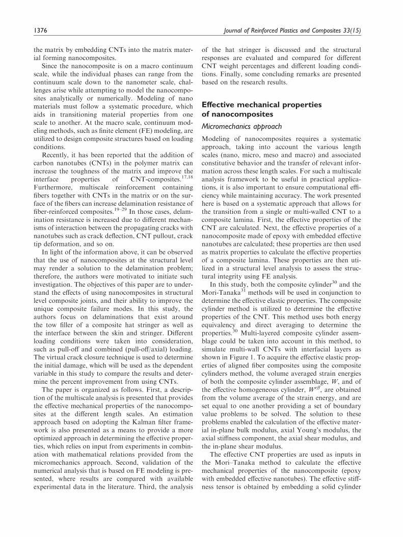
In this study, both the composite cylinder30 and theMori-Tanaka31 methods will be used in conjunction todetermine the effective elastic properties. The compositecylinder method is utilized to determine the effectiveproperties of the CNT. This method uses both energyequivalency and direct averaging to determine theproperties.30 Multi-layered composite cylinder assem-blage could be taken into account in this method, tosimulate multi-wall CNTs with interfacial layers asshown in Figure 1. To acquire the effective elastic prop-erties of aligned fiber composites using the compositecylinders method, the volume averaged strain energiesof both the composite cylinder assemblage, W, and ofthe effective homogeneous cylinder, Weff, are obtainedfrom the volume average of the strain energy, and areset equal to one another providing a set of boundaryvalue problems to be solved. The solution to theseproblems enabled the calculation of the effective mater-ial in-plane bulk modulus, axial Young’s modulus, theaxial stiffness component, the axial shear modulus, andthe in-plane shear modulus.
The effective CNT properties are used as inputs inthe Mori–Tanaka method to calculate the effectivemechanical properties of the nanocomposite (epoxywith embedded effective nanotubes). The effective stiff-ness tensor is obtained by embedding a solid cylinder
1376 Journal of Reinforced Plastics and Composites 33(15)
that has the effective CNT properties in the unknowneffective composite, and is obtained as32
C ¼ vmCm~Lm þ
XPl¼1
vlCl~Ll
!vmIþþ
XPl¼1
vp ~Lp
!�1
ð1Þ
~Ll ¼ Iþ SL�1m Ll � Lmð Þ� ��1
ð2Þ
where C represents the effective stiffness tensor, L isthe concentration tensor, v is the volume fraction, S isthe eshelby tensor, and I is the identity tensor. Theconcentration tensor (L) relates the average strain inthe effective cylinder to the average strain of thematrix and is perturbed by some amount to accountfor interactions between inclusions. S is obtained forcylindrical inclusions embedded in the matrix. Oncethe effective properties of the nanocomposite areobtained, they are used as the new matrix materialto formulate the nanocomposite lamina. Both unidir-ectional and woven composites can be consideredusing this approach.
In order to analytically model the nanocompositelamina, the stiffness matrix for an infinitesimal slicemust be obtained. This is done by adding stiffnessmatrices of the constituents as follows33
Kijðx, yÞ ¼XI
vIðx, yÞQI
ijðx, yÞ, i, j ¼ 1� 6 ð3Þ
where QI
ij is the transformed stiffness matrix (to theglobal frame) of the Ith element. Superscript I refers
to either the fill strand (F), the warp strand (W) whenconsidering woven composites, or the matrix (M). Tocalculate the global stiffness matrix Kglobalðx, yÞ, thelocal matrix Kijðx, yÞ is evaluated for a small slice overx and y directions in an averaged manner as follows
Kð yÞ ¼ 1=a
Z a
0
KðxÞdx ð4Þ
Kgobal ¼ 1=a
Z a
0
Kð yÞdy ð5Þ
where a represents the strand or fiber width. Equations(4) and (5) are used to calculate the effective propertiesof the nanocomposite lamina.
Estimation approach
An alternative approach in determining the effectivemechanical properties of the nanocomposites is investi-gated in this study. It is based on an estimation frame-work that utilizes the Kalman filter algorithm. Theprocess depends on user-defined mathematical modelsof the phenomenon under study, and measurementsacquired by a practical experiment or application tooptimally estimate certain parameters. The motivationin presenting the following method is to validate theresults obtained from the micromechanics approach,and to provide an alternative method to determinethe effective properties. The Kalman filter utilizesboth the micromechanics methods and results fromFE models to estimate the material properties.
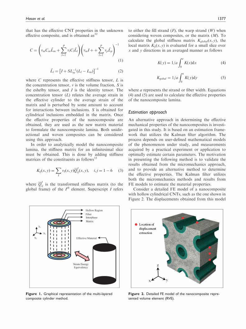
Consider a detailed FE model of a nanocompositewith hollow cylindrical CNTs, such as the one shown inFigure 2. The displacements obtained from this model
Figure 1. Graphical representation of the multi-layered
composite cylinder method.
Figure 2. Detailed FE model of the nanocomposite repre-
sented volume element (RVE).
Hasan et al. 1377
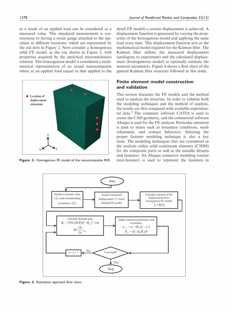
as a result of an applied load can be considered as ameasured value. This simulated measurement is syn-onymous to having a strain gauge attached to the spe-cimen at different locations, which are represented bythe red dots in Figure 2. Now consider a homogenoussolid FE model, as the one shown in Figure 3, withproperties acquired by the analytical micromechanicssolution. This homogenous model is considered a math-ematical representation of an actual nanocompositewhere at an applied load (equal to that applied to the
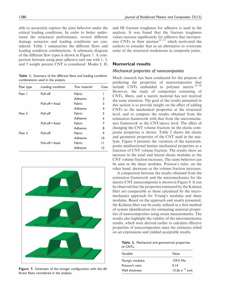
detail FE model) a certain displacement is achieved. Adisplacement function is generated by varying the prop-erties of the homogenous model and applying the sameload every time. This displacement function acts as themathematical model required for the Kalman filter. TheKalman filter utilizes the measured displacement(analogous to experiment) and the calculated displace-ment (homogeneous model) to optimally estimate thematerial parameters. Figure 4 shows a flow chart of thegeneral Kalman filter structure followed in this study.
Finite element model constructionand validation
This section discusses the FE models and the methodused to analyze the structure. In order to validate boththe modeling techniques and the method of analysis,the results are first compared with available experimen-tal data.6 The computer software CATIA is used tocreate the CAD geometry, and the commercial softwareAbaqus is used for the FE analysis. Particular attentionis paid to issues such as boundary conditions, meshrefinement, and contact behaviors. Selecting theproper fastener modeling technique is also a keyissue. The modeling techniques that are considered inthe analysis utilize solid continuum elements (C3D8I)for the composite parts as well as the metallic fixturesand fasteners. An Abaqus connector modeling routine(star-fastener) is used to represent the fasteners in
Figure 4. Estimation approach flow chart.
Figure 3. Homogenous FE model of the nanocomposite RVE.
1378 Journal of Reinforced Plastics and Composites 33(15)

the model. These connectors use multi-point con-straints (MPCs) to fix nodes on each surface in a fas-tener stack-up with respect to a central reference pointthat lies on the fastener axis centerline. Separate ‘‘axial’’and ‘‘shear’’ connector definitions are used at each fas-tener location to provide both in-plane and thru-thick-ness constraints to the surfaces in the fastener stack-up.
The virtual crack closure technique is used in thisanalysis to detect initial damage. When the stress inten-sity reaches the critical strain energy release rate, thecentral pair of nodes is released. A damage index isdefined as follows12
� ¼Gequiv
GequivC¼
GI
GIC
� �m
þGII
GIIC
� �n
þGIII
GIIIC
� �o
ð6Þ
where GI, GII, and GIII are the strain energy releaserates for modes I, II, and III fractures, respectively;GIc, GIIc, and GIIIc are the allowed toughness formodes I, II, and III fractures respectively; and super-scripts m, n, and o are equal to 1 in this study. Whenthis damage index reaches a unit value, it implies that anode has been released and initial damage has beendetected. In order to utilize the virtual crack closuretechnique, an initial flaw must be embedded in themodel. Usually, the flaw is inserted in locations wheredelamination is most likely to occur. In order to correl-ate to the available experimental data, a 0.75 inch�0.75 inch flaw is considered and inserted betweenthe tow filler and the web midway along the stringerspan, as shown in Figure 5, since delamination wasobserved to initiate from that location.6 It is note-worthy to mention that preload is applied to all thefasteners in the model and resin toughness values areused in the analysis to predict the initial damage.34 It isnoted that the failure is usually dominated by mode Ifracture, and the contribution of modes II and III is notsignificant. Figure 6 shows the correlation between theFE model and the experimental data. Note that thecorrelation was done to the initial damage load andnot the final failure load. A total of nine specimenswere tested that were 7 inches long and had varying
widths (1, 2, 3 inches).6 It can be observed that thepredicted initial damage from the FEM is within 10%of the results obtained from the test data. Note that theinitial damage predicted by the models is lower, indict-ing that the models provide a more conservative esti-mate. This correlation provided the authors withconfidence in both the analysis method and modelingtechniques, and therefore is used for the remaininganalysis.
Hat stringer analysis withembedded CNTs
Delamination is considered to be one of the primaryforms of failure in laminated composite structures,especially when there is no reinforcement in the thick-ness direction. In order to develop composite structuresthat are more tolerant, and resistant to interlaminarfailure, it is necessary to understand how delaminationdevelops and how it can affect the performance.Residual thermal stresses, matrix-curing shrinkage,and manufacturing defects are all factors that deter-mine how damage will initiate and grow in a compositestructure. The high stress gradients that occur in spe-cific hotspots in the structure, such as the tow filler andthe skin/stringer bondlines (that exist in composite hatstringers), promote damage initiation and may cause asignificant loss of structural integrity. The use of nano-composite in such critical locations may alleviate suchproblems and help improve the overall structuralperformance.
After having correlated to available experimentaldata, confidence was gained with the modeling tech-niques used in terms of fastener idealization, meshdensity, elements types, etc. The next step is to createa comparatively larger and detailed model with thesame modeling methods that incorporate the use offine grid mesh, especially in the area of interest, to be
281270
0
50
100
150
200
250
300
0 0.05 0.1 0.15 0.2 0.25 0.3
Lo
ad (l
b)
Displacment (inch)
TestModel Prediction
Figure 6. Correlation between the FE model and test.Figure 5. Embedded flaw used in the model.
Hasan et al. 1379
able to accurately capture the joint behavior under thecritical loading conditions. In order to better under-stand the structural performance, several differentdamage scenarios and loading conditions are con-sidered. Table 1 summarizes the different flaws andloading condition combinations. A schematic diagramof the different flaw types is shown in Figure 7. A com-parison between using pure adhesive and one with 1, 3,and 5 weight percent CNT is considered. Modes I, II,
and III fracture toughness for adhesive is used in theanalysis. It was found that the fracture toughnessvalues increase significantly for adhesive that incorpor-ates CNTs in their mixture35–37 which motivated theauthors to consider that as an alternative to overcomesome of the structural weaknesses in composite joints.
Numerical results
Mechanical properties of nanocomposites
Much research has been conducted for the purpose ofpredicting the properties of nanocomposites thatinclude CNTs embedded in polymer matrix.35–39
However, the study of composites consisting ofCNTs, fibers, and a matrix material has not receivedthe same attention. The goal of the results presented inthis section is to provide insight on the effect of addingCNTs to the mechanical properties at the structurallevel, and to compare the results obtained from theestimation framework with that from the micromecha-nics framework at the CNT/epoxy level. The effect ofchanging the CNT volume fraction on the elastic com-posite properties is shown. Table 2 shows the elasticand geometric properties of the CNT used in the ana-lysis. Figure 8 presents the variation of the nanocom-posite unidirectional lamina mechanical properties as afunction of CNT volume fraction. The results show anincrease in the axial and lateral elastic modules as theCNT volume fraction increases. The same behavior canbe seen in the shear modules. Poisson’s ratio, on theother hand, decreases as the volume fraction increases.
A comparison between the results obtained from theestimation framework and the micromechanics for thematrix/CNT nanocomposite is shown in Figure 9. It canbe observed that the properties estimated by the Kalmanfilter are comparable to those calculated by the micro-mechanics approach for Young’s modulus and shearmodulus. Based on the approach and results presented,the Kalman filter can be easily utilized as a first methodof system identification for estimating material proper-ties of nanocomposites using strain measurements. Theresults also highlight the validity of the micromechanicsresults, which were derived earlier to calculate effectiveproperties of nanocomposites since the estimates reliedon set expressions and yielded acceptable results.
Figure 7. Schematic of the stringer configuration with the dif-
ferent flaws considered in the analysis.
Table 1. Summary of the different flaws and loading condition
combinations used in the analysis.
Flaw type Loading condition Tow material Case
Flaw 1 Pull-off Fabric 1
Adhesive 2
Pull-off + Axial Fabric 3
Adhesive 4
Flaw 2 Pull-off Fabric 5
Adhesive 6
Pull-off + Axial Fabric 7
Adhesive 8
Flaw 3 Pull-off Fabric 9
Adhesive 10
Pull-off + Axial Fabric 11
Adhesive 12
Table 2. Mechanical and geometrical properties
of CNTs.
Variable Value
Young’s modulus 159.5 Msi
Poisson’s ratio 0.14
Wall thickness 13.26 e�9 inch
1380 Journal of Reinforced Plastics and Composites 33(15)

Failure analysis of composite stringersincorporating CNTs
A schematic diagram of the hat stinger model is shownin Figure 10. As mentioned earlier, different flaw typesare considered in this study as well as two types of
designs regarding the composite stringer; one thatuses adhesive to fill the tow region and another thatuses fabric. The reason for using these designs is thefact that both are typically utilized in the manufactur-ing of such stringers. Moreover, different compositelaminate designs (a design that use CNTs embedded
Figure 8. Effective properties of the nanocomposite lamina as a function of CNT volume fraction.
Hasan et al. 1381

in the matrix and others that use pure epoxy for thematrix material) are also studied. The loading condi-tions considered were pull-off and combined axial/pull-off. It is important to note that the value of the failureload depends on the location where the flaw isembedded in the structure. The peak running loadexists midway; hence, both flaw types 1 and 2 areembedded in the hat stringer in that location, whereasflaw type 3 is inserted at the stringer terminationbetween the stringer base and skin interface.
Figures 11–13 show the initial failure load by apply-ing a pure pull-off load for the three different flawtypes. Note that four different configurations regardingthe use of CNT in the structure were considered, andare summarized in Table 3. Figure 11 represents thepull-off failure load of the structure that incorporatesa flaw of type 1. The general trend that was observedfor both types of tow materials (fabric and adhesive)was the increase in failure load with increase in CNTweight fraction due to the added through thickness cap-ability. It is also noticeable from the figure that for allvalues of CNT weight fractions, the failure load for theadhesive tow is considerably larger than that for thefabric tow. In addition, when examining the adhesiveand fabric tow results, the failure load is higher whenboth the tow material and the composite lamina con-tain CNTs. Flaw type 1 was noted to be mode I dom-inant, which relies on the angle opening of the radiuswhere the pull-off load tends to open the radius creatinghigh energy release rates. Therefore, the use of CNTswas shown to give additional through thickness cap-ability, preventing or delaying such event from occur-ring. Figure 12 represents the pull-off failure load of thestructure that incorporates a flaw of type 2. In this case,the failure load increased with the increase in CNTweight percentage for both types of tow materials(fabric and adhesive). It can also be observed that thefailure load for the adhesive tow is significantly largerthan that for the fabric tow. By considering only the
(a) (b)
(d)(c)
Figure 9. Effective properties of the nanocomposite as a function of CNT volume fraction—estimated and calculated.
Figure 10. 3D mesh of the hat stringer.
1382 Journal of Reinforced Plastics and Composites 33(15)

adhesive tow results, the failure load was higher whenonly the adhesive tow contains CNTs; therefore, thereis no additional gain from using CNTs in the compositelamina. On the other hand, when considering the fabrictow configuration, the failure load is higher when boththe tow material and composite contain CNTs. Flawtype 2 was also found to be mode I dominant underpull-off loading, and the use of CNTs was shown togive additional through thickness capability preventingor delaying such events from occurring. It can also benoted that the failure load is much higher for this flawtype compared to the previous case, which means thatthe structure has more capability of sustaining add-itional load with the inclusion of this flaw type under
pull-off loading. That is an important observation whendesigning the structure from the damage-tolerance per-spective. Figure 13 represents the pull-off failure load ofthe structure that incorporates a flaw of type 3. As inthe previous two cases, the failure load increases withincrease in CNT weight percentage; however, for the
Table 3. Different configurations considered in the analysis.
Configuration Use of CNT
1 Adhesive Tow (CNT was used in the adhesive
layer surrounding the tow filler and the tow
filler itself. CNT was also used in the adhesive
layer that exists between the skin and stringer
interface)
2 Adhesive Tow (CNT was used in the adhesive
layer surrounding the tow filler and the tow
filler itself. CNT was also used in the adhesive
layer that exists between the skin and stringer
interface. In addition, CNT was used in the
composite laminates of the stringer and skin)
3 Fabric Tow (CNTwas used in the adhesive layer
surrounding the tow filler and the tow filler
itself. CNT was also used in the adhesive layer
that exists between the skin and stringer
interface)
4 Fabric Tow (CNTwas used in the adhesive layer
surrounding the tow filler and the tow filler
itself. CNT was also used in the adhesive layer
that exists between the skin and stringer
interface. In addition, CNT was used in the
composite laminates of the stringer and skin)
Figure 13. Pull-off failure load for flaw 3 considering different
configurations.
Figure 12. Pull-off failure load for flaw 2 considering different
configurations.
Figure 11. Pull-off failure load for flaw 1 considering different
configurations.
Hasan et al. 1383

fabric tow, the failure load increases up until 5% CNTby weight where it drops slightly. When examining theadhesive tow results, the failure load is higher whenboth the adhesive and the composite lamina containCNTs and the same statement holds for the fabrictow. Flaw type 3 was found to have a mode mix ofboth I and II under pull-off loading, and the use ofCNT was shown to give additional through thicknesscapability in this case as well.
The combined loading effect is addressed next. Boththe axial and pull-off loads are applied simultaneously;therefore, the cause of initial damage is not distinguish-able. Figure 14 shows a schematic diagram of the load-ing condition. Figures 15–17 show results for the sameweight fractions, flaw types, and tow design as shownpreviously for the pure pull-off case. However, theydiffer in the loading condition that was applied; inthis case, combined axial/pull-off was applied to the
structure. In these figures, only the axial load atwhich initial failure occurred was reported. Figure 15represents results from considering a flaw of type 1.The dominating trend that can be observed was thatthe axial failure load increased as the CNT weight frac-tion increased. Also, the axial failure load for the fabrictow was always larger than that of the adhesive tow forall cases. There is, however, substantial gain in failureload if the CNTs were used in both adhesive and com-posite lamina. Figure 16 represents the axial failureload of the structure that incorporates a flaw of type2 under combined axial/pull-off load. It can be
Figure 15. Axial failure load for flaw 1 by applying a combined
axial/pull-off load for different configurations.
Figure 16. Axial failure load for flaw 2 by applying a combined
axial/pull-off load for different configurations.
Figure 17. Axial failure load for flaw 3 by applying a combined
axial/pull-off load for different configurations.
Figure 14. Schematic diagram of the combined loading
condition.
1384 Journal of Reinforced Plastics and Composites 33(15)
observed for both types of tow materials (fabric andadhesive) that as the CNT weight fraction increases,the failure load increases. It is also clear from thefigure that for all values of CNT weight fractions, thefailure load for the adhesive tow is larger than that forthe fabric tow. Moreover, the failure load is higherwhen the CNTs are only used in the adhesive. Thismay be attributed to the location of the flaw and itsinteraction with the surrounding structure under theapplied axial load. Figure 17 represents the axial failureload of the structure that incorporates a flaw of type 3.For both types of tow material, it can be observed thatas the CNT weight fraction increases, the failure loadincreases. It is also obvious from the figure that for allvalues of CNT weight fractions, the axial failure loadfor the fabric tow was larger than that for the adhesivetow. In addition, the failure load for cases of CNTsbeing present in the adhesive and composite laminawas larger than when only having it used in the adhe-sive. Note that a substantial increase in failure load isobtained for having CNTs weight of 3% and above forthe design that incorporates the use of fabric tows, andCNT used in the adhesive and composite lamina.
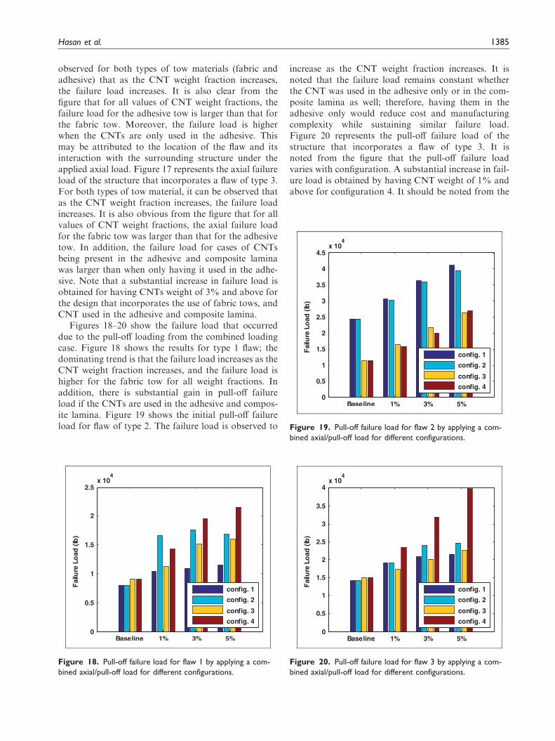
Figures 18–20 show the failure load that occurreddue to the pull-off loading from the combined loadingcase. Figure 18 shows the results for type 1 flaw; thedominating trend is that the failure load increases as theCNT weight fraction increases, and the failure load ishigher for the fabric tow for all weight fractions. Inaddition, there is substantial gain in pull-off failureload if the CNTs are used in the adhesive and compos-ite lamina. Figure 19 shows the initial pull-off failureload for flaw of type 2. The failure load is observed to
increase as the CNT weight fraction increases. It isnoted that the failure load remains constant whetherthe CNT was used in the adhesive only or in the com-posite lamina as well; therefore, having them in theadhesive only would reduce cost and manufacturingcomplexity while sustaining similar failure load.Figure 20 represents the pull-off failure load of thestructure that incorporates a flaw of type 3. It isnoted from the figure that the pull-off failure loadvaries with configuration. A substantial increase in fail-ure load is obtained by having CNT weight of 1% andabove for configuration 4. It should be noted from the
Figure 18. Pull-off failure load for flaw 1 by applying a com-
bined axial/pull-off load for different configurations.
Figure 19. Pull-off failure load for flaw 2 by applying a com-
bined axial/pull-off load for different configurations.
Figure 20. Pull-off failure load for flaw 3 by applying a com-
bined axial/pull-off load for different configurations.
Hasan et al. 1385

previous results that the axial failure load is muchhigher than the failure that occurs from pull-off.Moreover, combined loading consideration is animportant part in the analysis and design process ofsuch structures; since, as was observed, the failureloads could be under or overestimated providing astructure that might be less conservative or overlydesigned, respectively.
From the results presented in this section, it can beconcluded that an aerospace structure (such as strin-gers) subjected to pull-off loading the use of CNTs inspecific hot spot locations, such as the tow-stringer webinterface or the bondline location between the skin andstringer, can prevent or delay the onset ofdelamination.
Conclusion
The present study focused on the benefits of usingnanocomposites in structural level components thatare typically used in aerospace applications. An exam-ple of such structure was a typical hat stringer. A multi-scale approach was used to determine the effectiveproperties of the nanocomposite at different lengthscales. These effective properties were used in the FEmodels. An alternative approach in determining theeffective mechanical properties was also presented; itwas based on an estimation method using the Kalmanfilter. The results were compared with those obtainedfrom the micromechanics approach. It was found thatthe Kalman filter can be easily utilized as a first methodof system identification for estimating material proper-ties of nanocomposites using strain measurements. Theresults also highlight the validity of the micromechanicsresults.
A detailed model was constructed of the Hat stin-ger bonded to a skin in order to assess the use ofnanocomposites in structural level components toimprove some of the weak spots in such structures.The virtual crack closure technique was adopted inorder to determine the initial damage of the structure,defined as the initial load drop in the load displace-ment curve. Different configuration, flaw types, andloading conditions were considered in this study. Bycomparing the initial failure loads it was shown thatusing CNTs in the manufacturing process of suchstringers might improve the overall performance upto 35%. It was also concluded that when consideringa structure that experiences pull-off loading, the use ofCNTs in hotspot locations, such as the tow-stringerweb interface or the bondline location between theskin and stringer interface, the delamiantion thatoccurs in those locations can be prevented or delayedthereby providing a much more robust structuraldesign.
Funding
The authors are grateful for the support of NAVAIR grant,
sponsored by Integrated Systems Solutions (Grant number:W911NF-12-1-0353).
Conflict of interest
None declared.
Acknowledgement
Dr Nam Phan is the program manager.
References
1. Ostergaard M, Ibbotson A, Le Roux O, et al. Virtual
testing of aircraft structures. Aeronaut J 2011; 1: 83–103.
2. Martin R. Local fracture mechanics analysis of stringer
pull-off and delamination in a post-buckled compression
panel. J Appl Compos Mater 1996; 3: 249–264.3. Krueger R, Cvitkovich M, O’brien K, et al. Testing and
analysis of composite skin/stringer debonding under
multi-axial loading. J Compos Mater 2000; 34:
1263–1300.4. Winzen A. Simulation of stringer stiffened CFRP panels in
consideration of skin-stringer separation. Master Thesis,
Aachen University of Applied Sciences, Department of
Aerospace Technology, Germany, 2006.5. Hoyt D, Ward S and Minguet P. Strength and fatigue life
modeling of bonded joints in composite structure.
J Compos Technol Res 2002; 24: 188–208.6. Li JA, Brien TK and Rousseau CQ. Test and analysis of
composite hat stringer pull-off test specimens. J Am
Helicopter Soc 1997; 42: 350–357.7. Cope RD and Pipes RB. Design of the composite spar–
wing skin joint. J Compos 1982; 13: 47–53.8. Rispler AR, Steven GP and Tong L. Failure analysis of
composite T-joints including inserts. J Reinf Plastics
Compos 1997; 16: 1642–1658.9. Kumari S and Sinha PK. Finite element analysis of wing
T-joints. J Reinf Plastics Compos 2002; 21: 1561–1585.
10. Zimmermann K, Zenkert D and Siemetzki M. Testing
and analysis of ultra thick Composites. J Compos Part
B 2010; 41: 326–336.
11. Helenon F, Wisnom MR, Hallett SR, et al. Numerical
investigation into failure of laminated composite T-piece
specimens under tensile loading. J Compos Part A: Appl
Sci Manuf 2012; 43: 1017–1027.
12. Panigrahi SK and Pradhan B. Delamination damage ana-
lyses of FRP composite spar wing skin joints with mod-
ified elliptical adhesive load coupler profile. J Appl
Compos Mater 2008; 15: 189–205.
13. Panigrahi SK and Pradhan B. Development of load coup-
ler profiles of spar wingskin joints with improved per-
formance for integral structural construction of aircraft
wings. J Reinf Plastics Compos 2009; 28: 657–673.
14. Chen J, Ravey E, Hallett S, et al. Prediction of delamin-
ation in braided composite T-piece specimens. J Compos
Sci Technol 2009; 69: 2363–2367.
1386 Journal of Reinforced Plastics and Composites 33(15)

15. Tong L, Mouritz A and Bannister M. 3D fibre reinforced
polymer composites, 1st ed. Boston: Elsevier, 2002,
pp.1–12.16. Dransfield K, Jain L and Mai Y. On the effects of stitch-
ing in CFRPs-I. mode I delamination toughness.
J Compos Sci Technol 1998; 58: 815–827.17. Thostenson E, Ren Z and Chou T-W. Advances in the
science and technology of carbon nanotubes and their
composites: a review. J Compos Sci Technol 2001; 61:
1899–1912.18. Abdala M, Dean D, Adibempe D, et al. The effect of
interfacial chemistry on molecular mobility and morph-
ology of multiwalled carbon nanotubes epoxy nanocom-
posite. J Polymer 2007; 48: 5662–5670.19. Bekyarova E, Thostenson ET, Yu A, et al. Multiscale
carbon nanotube–carbon fiber reinforcement for
advanced epoxy composites. Langmuir 2007; 23:
3970–3974.20. Garcia EJ, Hart AJ and Wardle BL. Long carbon nano-
tubes grown on the surface of fibers for hybrid compos-
ites. J AIAA 2008; 46: 1405–1412.21. Garcia EJ, Wardle BL, Hart AJ, et al. Fabrication and
multifunctional properties of a hybrid laminate with
aligned carbon nanotubes grown in situ. J Compos Sci
Technol 2008; 68: 2034–2041.22. Godara A, Warrier A, Mezzo L, et al. Influence of
carbon nanotube reinforcement on the mechanical behav-
ior of carbon fiber/epoxy composites. In: SAMPE 2008,
Europe international conference and forum, Paris, 8–11
September 2008.23. Godara A, Warrier A, Mezzo L, et al. Influence of
carbon nanotube reinforcement on the processing and
the mechanical behaviour of carbon fiber/epoxy compos-
ites. J Carbon 2008; 47: 2914–2923.24. Wichmann MHG, Sumfleth J, Gojny FH, et al. Glass-
fibre-reinforced composites with enhanced mechanical
and electrical properties – benefits and limitations of a
nanoparticle modified matrix. J Eng Fract Mech 2006; 73:
2346–2359.25. Qian H, Bismarck A, Greenhalgh ES, et al. Hierarchical
composites reinforced with carbon nanotube grafted
fibers: the potential assessed at the single fiber level.
J Chem Mater 2008; 20: 1862–1869.26. Qu LT, Zhao Y and Dai LM. Carbon microfibers
sheathed with aligned carbon nanotubes: towards multi-
dimensional, multicomponent, and multifunctional nano-
materials. J Small 2006; 2: 1052–1059.
27. Romhany G and Szebenyi G. Interlaminar crack propa-gation in MWCNT/ reinforced hybrid composites.eXPRESS Polymer Lett 2009; 3: 145–151.
28. Tan P, Tong L and Sun X. Effective properties for plainweave composites through thickness reinforced withcarbon nanotube forests. J Compos Struct 2008; 84: 1–10.
29. Thostenson ET, Li WZ, Wang DZ, et al. Carbon nano-
tube/carbon fiber hybrid multiscale composites. J ApplPhys 2002; 91: 6034–6037.
30. Christensen R and Lo K. Solutions for effective shear
properties in three phase sphere and cylinder models.J Mech Phys Solids 1979; 27: 315–330.
31. Mori T and Tanaka K. Average stress in matrix and
average elastic energy of materials with misfitting inclu-sions. Acta Metallurg 1973; 21: 571–574.
32. Gary DS and Dimitris CL. Micromechanical analysis of
the effective elastic properties of carbon nanotube rein-forced composites. J Mech Mater 2006; 38: 884–907.
33. Scida D, Aboura Z, Benzeggagh ML, et al. A microme-chanics model for 3D elasticity and failure of woven-fiber
composite materials. Journal Composites and Science andTechnology 1999; 59: 505–517.
34. Li J and Sen J. Analysis of frame-to-skin joint pull-off
tests and prediction of the delamination failure. In:Proceedings of the 42nd structures, structural dynamics,and materials (SDM) conference, Seattle, Washington,
AIAA-2001-1484, 16–19 April 2001.35. Kumar JSP, Raghava G and Stanley AJ. Fracture tough-
ness of multi walled carbon nano tubes modfied polymercomposite in mode – I. J Mater Sci Res 2012; 1: 117–123.
36. Hsieh T, Kinloch A and Taylor A. The effect of carbonnanotubes on the fracture toughness and fatigue perform-ance of a thermosetting epoxy polymer. J Mater Sci 2011;
46: 7525–7535.37. Thakre P, Lagoudas D, Riddick J, et al. Investigation of
the effect of single wall carbon nanotubes on interlaminar
fracture toughness of woven carbon fiber–epoxy compos-ites. J Compos Mater 2011; 0: 1–17.
38. Selmi A, Friebel C, Doghri I, et al. Prediction of the
elastic properties of single walled carbon nanotube rein-forced polymers: A comparative study of several micro-mechanical models. J Compos Sci Technol 2007; 67:2071–2084.
39. Peeterbroeck S, Breugelmans L, Alexandre M, et al. Theinfluence of the matrix polarity on the morphology andproperties of ethylene vinyl acetate copolymers-carbon
nanotube nanocomposites. J Compos Sci Technol 2007;67: 1659–1665.
Hasan et al. 1387