an investigation of the electrical precipitation of spray
TRANSCRIPT
t)
THESIS 'D
- on
An Investigation of The Electrical Precipitation of Spray and Fog by 60 Cycle Alternation Current Fields.
Submitted to the
OREGON STATE AGRICULTURAL COLLEGE
In partial fulfillment of the requirements for the
Degree of
MASTER OF SCIENCE
by
James Browniow Manning
April 30, 1932

APPROVED:
Redacted for privacy Research Professor of Electrical Enineerinp
Redacted for privacy
Head of Departnient of Electrical Engineering
Redacted for privacy
Chalrrnqn of Conmiittee on Graduate Study

mt roduc ti on
In close proxiîilty to the sea coast, Great Salt
Lake, the Gulf of Mexico, and other locations the insulat-
Ing value of insulators Is greatly decreased due to "salt
fogs." Electric Light and Power Companies operating trans-
mission lines and otber outdoor electrical equipment sub-
ject to these fogs use diverse methods for combating the
conducting deposits formed. Some companies increase the
size of their Insulators on low voltage lines when economi-
cally feasible. The Southern California Edison Company
has installed permanent fresh water spray equipment in im-
portant substations for washing the insul8tors daily. One
company serving Vera Cruz, Mexico has built a double line
into the city for some six or eight kilometers, and during
a certain season of the year keep one man busy washing
these insulators. All of these methods result In increas-
ed expenditures for the Installation and maintenance of
transmission and distribution systems.
Formation of "Salt Fogs"
"Salt fogs" are caused by the mechanical break-
ing up of salt water by waves, and the breakers in the
surf. The fine spray of small particles containing the
various dissolved constituents of the salt water are pro-
ected into the air, and are carried over the land under
favorable wind conditions. This salt laden spray is de-
posited. on Insulators, and as the water Is evaporated the
salt residue is left on the insulating surface. This resi-

due accwnulates at a rate depending upon the frequency and
duration of the "salt fogs."
Because of the nature of formation the "salt
fog" particles will have a definite electrical charge, and
lt was believed that lt would be pössible to provide some
kind of shielding apparatus to electrically precipitate the
undesirable conducting material before lt reaches the in-
sulator surface.
Construction of Apparatus
The first part of the problem consisted in build-
in some apparatus for the investigation. Therefore, work
was started early in the fall term of 1931-'32 to assemble
the necessary equipment for the experiment.
A supporting structure for the insulator under
test was first assembled. This consisted of an A frame
structure of the correct heitht to support the insulator,
the electrical shield, and the spray nozzle with the
screen for breaking up the spray. This structure is shown
In Fig. 1.
The next problem was to arrange for a higYi
voltage conductor from the transformer to the insulator
under test. One-quarter inch pipe was selected for this
purpose because it is sufficiently ricid to support its
own weight, and also approximates the size of conductor
t1'at one usually finds in use on 66 KV. transmission
lines. In order to reduce the mechanical load on the

transformer bushing to a minimum an insulating. wood sup-
port vas bolted to the top of the transformer tank to sup-
port the one-quarter inch pipe conductor for energizing
the insulator. The other high voltage terminal of the
transformer was connected directly to ground.
It was neceasary to produce a spray similar to
fog, and after muc)i experimenting the Spray Engineering
Company's nozzle "Spraco" #3B with some modifications was
found to be best for the purpose. This nozzle consists of
an external chamber which has an opening for the water or
spray to pass through. Within this chamber there is a
spinner or turbine which has a central hole passing direct-
'y through it. On the outside of the spinner there are
two spiral grooves running from front to back. As the
water passes through these spiral grooves the spinner is
caused to rotate, which gives the water' a whirling motion
and breaks it up into a fine spray. The central hole of
the spinner within the nozzle was plugged with wood, and.
the resultant spray with a water pressure ranging from
fifty to sixty-five pounds was fairly fine, but had a
rather high velocity. In order to reduce this velocity to
a low value a screen with twenty meshes per inch was
placed about three inches in front of the ttSpracoU nozzle.
This screen not only reduced the velocity of the water
particles, but also broke them up so that a very fine
spray or fog vías obtained. This spray was light enough to
be shifted in its course by the wind, and blown around
quite freely.
A spray of steam was also used in place of the
water stream. This was obtained from the Apperson Hall
heating system, and really produced a condition more
representative of actual fog conditions.
Voltage Supply
Voltage for the experiment was obtained by
transforming an adjustable O-110 volt alternating current
supply, controlled by hand rheostats to 38,200 volts, the
normal line to neutral voltage for a 66,000 volt three
phase circuit.
The ratio of the transformer was carefully check-
ed by measuring the voltage on the high voltage side with
a 6.25 cm. sphere gap, and simultaneous voltmeter readings
on the low voltage side. The ratio under no load was
found to vary from 750 at 11,820 volts to 792 at 65,800
volts. At the test voltage, 38,200 volts, the ratio was
found to be 780. The transformer and control equipment
is shown in Fig. 2.
Investigation of Electrical Precipitation of Spray and Fog by 60 Cycle Alternating Current Fields.
The primary object of this experiment was to
observe the electric field on the fog surroundIng an in-
sulator under various conditions.
With a potential of 38,200 volts applied between
the conductor onthe insulator and the Insulator pin the
water spray was directed toward the insulator. Under
this condition no particular phenomenon was observed to
take place on the spray within the dielectric field.
With a flat metal plate placed on top of the
insulator, and connected to the conductor the observa-
tions were repeated, and again no noticeable phenomenon
on the spray took place. The same was true when a erad-
Ing shield was connected to the pin or grounded side of
the Insulator, and with the flat. shield at the top of the
insulator.
With a circular grading shield connected to th
conductor, and placed around the top of the insulator at
a height slIghtly above the top shell, and a second grad-
Ing shield at the base of the insulator and grounded
there was a pronounced tendency for the drops of water
that collected on the top shield to be repelled from the
Insulator as they dropped off of the shield. However,
there was no noticeable effect on the spray in the di-
electric field between the two shields.
An insulator with the head and entire upper sur-
face of the top shell coated with a thin film of copper,
applied by the Shoupe process, was substituted for the
standard insulator, and the observations repeated. A
much stronger repelling force was noticed to take place
on the drops of water that fell from the top grading

shield than formerly. This was to be expected because the
applied potential was extended to the edge of the top shell
which increased the electric field between the edge of the
top shell, and the gradinc rinc on the pin. This gave a
greater repelling force against all charged particles
fal1in within this field.
A screen having fourteen meshes per inch was
tied to the grading shield so that the water spray had to
pass through this screen. When directed toward the in-
sulator it was noted that there was a great deal more rim
off of water from the screen when the voltage was applied
than when not applied.
The same experiment was tried except the screen
was placed five inches from the shielding ring. The large
run off of water was noted as formerly.
Further experiments were tried with the screen
at various distances from the shielding ring, and it was
found that the most effective distance was about five
inches. At approxiately seven inches the dielectric
field began to lose its effect on the water spray, and at
distances much greater than this there was no noticeable
effect on the water spray as it collected on the screen.
iJeasurerents were taken of the run off of water
from the insulator while shielded with a shieldIng ring,
and shielding screen five inches from the shielding ring.
With the voltage applied there was only 43.6% as much run

off of water from the insulator over a period of one hour
as there was with no voltage applied. This shows that the
dielectric field under these particular conditions was
able to repel 56.4% of the water spray away from the in-
sulator.
The fog stream was next produced by steam from
the Apperson Hall heating system. with this condition,
and the shielding as above described the run off from the
shielding screen was noticeable when the voltage was ap-
plied, but with no voltage applied there was no noticeable
run off from the shielding screen.
The next test was to over-stress the air sur-
rounding the insulator, and to do this a #20 AWG. bare
copper wire was used for a shielding ring at the top of
the insulator. The voltage was increased to 66,000 volts,
and at no time was there any noticeable change that took
place on the fog stream within the dielectric field.
Insulator Leakage
A number of different insulators were tested for
leakage current when dry, when subject to a water spray,
and when subject to a steam bath. The results obtained
are shown in Table I, The insulators tested are shown in
Figures 3 and 4. General information on these insulators
is given in Table II.

Distance Traveled by a Charged water Particle in an Alternating Electric Field.
In order to determine whether the experimental
results obtained are in accordance with the laws of mech-
anics and electricity equations were derived for calculat-
ing the distance traveled in one-half cycle by a charged
water particle, in air, acted upon by the combined forces
of gravity and a sinusoidal alternating electric field.
The equations used are shown in Appendix I.
Since the action on a water particle in an elec-
tric field depends on both the field voltage gradiente, and
the charge on the particles, calculations were made to
determine the maximum possible electric charge on a foc
particle of the mean size as determined by . J. Humphreys
The maximum charge possible is the quantity of electricity
that will raise the voltage gradient at the surface of the
particle to the ionizing point for the surrounding air.
These calculations are given in Appendix II.
The maximum electric field obtainable is de-
termined by the dielectric strength of air which is ap-
proximately 30 kv. per centimeter at 25 degrees temper-
ature, and a barometric pressure of 76 centimeters of
mercury. For other conditions of atmospheric temperature,
and pressure the dielectric strength of the air is di-
rectly proportional to the air density factor S.
C - 3.92 X b - 273 * t
'the re b barometric pressure in Cm. of H. t temperature in decrees C
Curves were plotted for various conditions of
dielectric field gradient, charge on particle, and size
of particle.
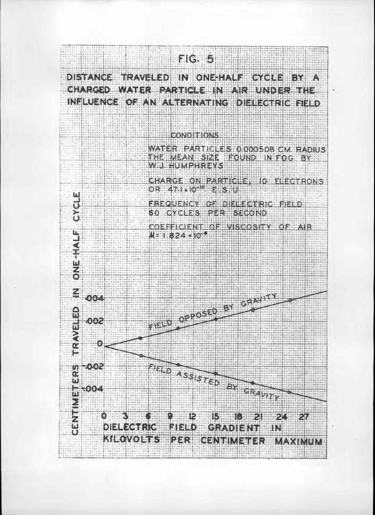
The distance traveled in one-half cycle by a
0.000508 cri. radius water particle having an electric
charge of 10 electrons, end acted upon by a 60 cycle
sinusoidal electric field varying in gradient from O to
30 kv. maximum per centimeter is shown graphically in
Figure 5. The size 0.000508 cm. was selected because it
is the mean size for fog particles found by . J.
Humphreys. It will be observed that with no electric
field such a particle will fall 0.000258 cm. in O.0083
seconds (one-half of a 60 cycle wave) because of the
action of gravity. A sinusoidal 60 cycle voltage grad-
lent of 1.8 kv. maximum per centimeter applied in oppo-
sition to gravity will just return the particle to the
starting position at the end of one-half cycle. The max-
imum distance this average size of water particle, with
a ten electron charge, can travel with the maximum poss-
ible electric field gradient of 30 kv. per centimeter Is
0.00512 centimeters with gravity, and 0.00461 centimeters
in opposition to gravIty.
The distance traveled in one-half cycle by a
0.000508 cm. radius water particle having the maximum

electric charge of 54,700 electrons, and with all other
conditions as above is shown in Figure 6. It will be ob-
served that the maximum distance traveled by this highly
charged particle under the maximum field gradient of 30
kv. per centimeter is 26.58 cm. in one-half cycle. The
action of gravity is so small in comparison to the action
caused by the electric field that it can be neglected.
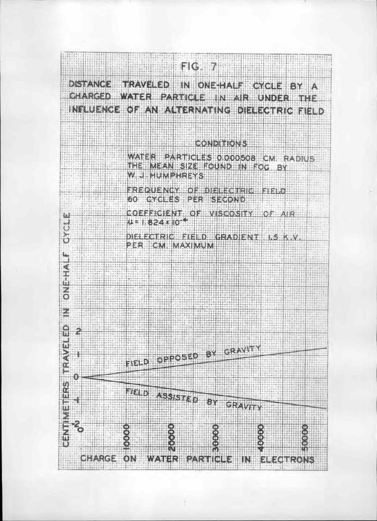
The distance traveled in one-half cycle by a
0.000508 cm. radius water particle having a charge varying
from O to 54,700 electrons, and acted upon by a 60 cycle
1.5 kv. maximum per cm. Jielectric field is shown in Fig-
ure 7. It will be observed that the maximum distance
traveled by this particle when charged with 54,700 elec-
trons is 1.33 cm. The action of gravity is small in com-
parison to the action caused by the electric field, and
may be neglected.
The distance traveled in one-half cycle by a
0.000508 cm. radius water particle having a charge vary-
Ing from O to 54,700 electrons, and acted upon by a 60
cycle 30 kv. maximum per centieter dielectric field is
shown graphically in Figure 8. It will be observed that
the maximum distance traveled by this particle in one-
half cycle when charged with 54,700 electrons is 26.58 cm.
The action of gravity is so small in comparison to the
action caused by the electric field that it may be neg-
lect,ed.
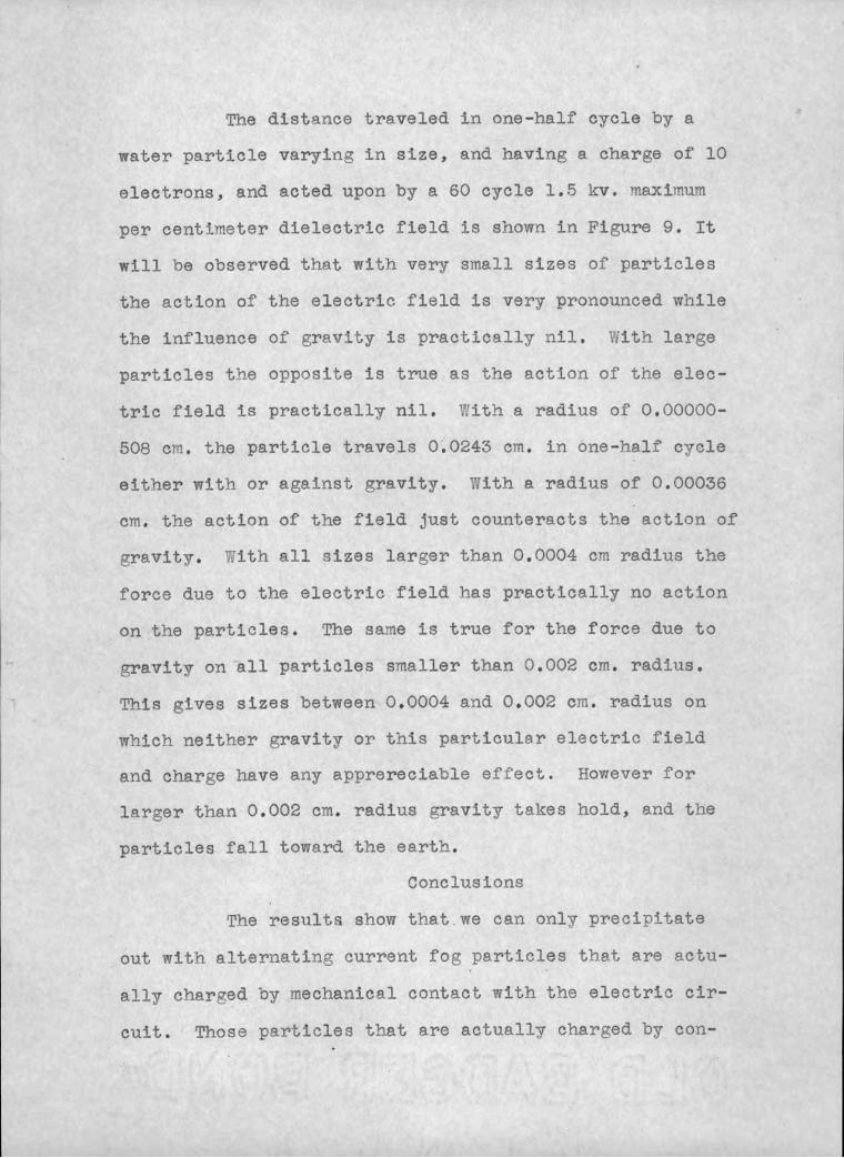
The distance traveled in one-half cycle by a
water particle varying in size, and having a charge of 10
electrons, and acted upon by a 60 cycle 1.5 kv. maximum
per centimeter dielectric field Is shown in Figure 9. It
will be observed that with very small sizes of particles
the action of the electric field is very pronounced while
the influence of gravity is practically nil. Vilth large
particles t'ne opposite is true as the action of the elec-
tric field is practically nil. V;ith a radius of 0.00000-
508 cm. the particle travels 0.0243 cm. in one-half cycle
either witi or against gravity. With a radius of 0.000$6
cm. the action of the field just counteracts the action of
gravity. ith all sizes larger than 0.0004 cm radius the
force due to the electric field has practically no action
on the particles. The same is true for the force due to
gravity on all particles smaller than 0.002 cm. radius.
This gives sizes between 0.0004 and 0.002 cm. radius on
which neither gravity or this particular electric field
and charge have any apprereciable effect. However for
larer than 0.002 cm. radius gravity takes hold, and the
particles fall toward the earth.
Conclus ions
The results show that we can only precipitate
out with alternating current fog particles that are actu-
ally char'zed by mechanical contact with the electric cir-
cuit. Those particles that are actually charged by con-

tact with the electric circuit can be filtered out by
alternating current fields. It should be kept in mind
that the dielectric field is changing 120 times per second
on a sixty cycle system which does not give the particles
much time to settle on an anode or cathode. The particles
therefore must be charged by the anode or cathode, and be
made to cling thereto until gravity pulls them off.
The results obtained under the insulator leakage
tests show that on every type of insulator tested the
leakage current is greater under a steam bath tben under
the water spray. This ws to be expected since the steam
more nearly duplicates fog conditions, and settles on all
surfaces of the insulator while the water spray covers the
top and sides of the insulator. With tbe exception of the
results obtained on the line post type insulator C-B8 the
difference in leakage current on the several insulator3 is
not large enough to merit special consideration. The line
post type insulator because of fts very much greater leak-
age distance and smaller circumference, decreases the
leakage current materially as compared to the ordinary
insulator.
Acknowledgment
This problem was undertaken at the
suggestion of F. O. McMilian,
Research Professor of Electrical
Engineering. I wish to take this
opportunity to thank him for his
interest, and sugestions through-
out the experiment.

Bibliography
Many engineering articles were investigated for
references on the subject. Those few that have any bear-
in on the subject are given below.
1. Controlling Insulation Difficulties in the Vicinity
of Great Salt Lake, by B. F. 1oward. AlEE Journal
1926, page 1268.
2. High Voltage easurernents on Cable and Insulators, by
C. L. 1asson. AlEE Journal 1927, page 1065.
3. Influence of Atmospheric Pollution of Performance of
Line Insulators, by B. L. Goodlet and J. B. "itford.
Electrician, January 25, 1929, page 91.
4. Spray and Fog Tests on 220 K.V. Insulators, by
R. J. C. Wood. AlEE Journal 1929, page 900.
5. Spray and Fog Tests on 220 K. V. Insulators, by
R. J. C. Vood. AlEE Journal, January 1930 page 9.
6. Special Pattern Insulators for use in Elaces Exposed
to Salt Fogs. Electrician, January 31, 1930, page 133
7. Effect of Atmospheric Conditions on Insulators by
G. R. F..Nuttall. World Power, June 1930 page 561.
8. Designing Insulators to Combat Fog, by S. Murray
Jones. Electrical World, December 1930, page 1139.
9. impulse Flashover of Insulators, by J. J. Torok and
w. Ramberg. AlEE Journal 1928, page 864.
10. The Electron, by Robert Andrews Millikan. The
University of Chicago Press.

11. Some Properties of Atons and Electrons as Measured
by Students, by Frederic Palmer, Jr. Journal of
the Optical Society of America and Review of
Scientific Instruments. Vol. 7, No. 10, Oct. 1923.
12. Focs and Clouds, by W. J. Hurnphreys. The 7;illiams
and ìi1kins Company.
13. Dielectric Phenomena in H1h-Voltage Engineering,
Third Edition, by F. V. Peek, Jr. McGraw-Hill Book
Company, Inc.
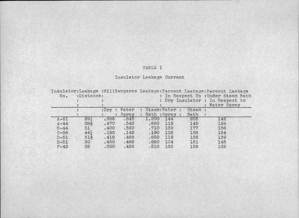
TABLE I
Insulator Leakage Current
Insulator:Leakage :Mllllaniperes Leakace:Percent Leakage :Percent Leakage No. :Distance: : In Respect To :Under Steam Bath
: : : Dry Insulator : In Respect to : : : : Water Spr8y
-. :Dry : Water StenuWater : Steam : : : Spray : Path :Spray : Bath
A-6l 29 .586 .845 1.200 144 205 142 A-44 28 .470 .540 .680 115 145 126 B-44 31 .400 .520 .710 1.30 177 136 C-88 44 .120 .142 .190 118 158 134 D-51 31 .418 .468 .650 112 155 139 E-51 30 .450 .468 .680 104 151 145 F-42 35 .320 .426 .510 133 159 122

TABLE II
General Inforiation on Insulators Tested for Leskage Current
Insulator No. Catalog No. Nominal Volta.e Rating Dry Flashover Voltage Wet Flashover Volt a ge We i Rht
Test Voltfge of anufacturer easured Leakage
Distance Wet Arcing Distance
A-44 F-44 C-88 D-51 E-51 F-42 A-61 3555 7215 8281 3060 82-A 12552 Special
60,000 66,000 66,000 66,000 60,000
180,000 not
given 27.62 lbs. not given 28.50
in. 10.00
in.
195,000
140,000 31.88 lbs. not given 31.00
in. 10.50
in.
175 , 000 not
given 45.25 lbs. not given 44.25
in. 17.50
in.
180,000 180,000
125,000 32.19 lbs. not given 31.50
in. 10.20
in.
140,000 31.12 lb s. not given 30.00
in. 10.00
1n.
66,000 no t
given not given 30.44 lbs.
190,000 35.00
in. 9.50 in.
60,000 not
given no t given 28.62 lbs. not
given 29.25
in. 8.50 in.

Ij
l-a.
rjq
o
o o
tu
i I-4
o
CI)
rJ
o
Ii (D
C)
l-j.
'-I.
l-j. o
(D
cg)
Cn
'-u
l-a.
(D
O)
ç:
I-'
o
cg)

Fig. 2 Transformer and Control Equipment for Spray and Fog Precipitation Tests on Insulators

A 44
B 44
A 61
D 51
E 51
F 42
Fig. 3 Insulators used for the Surface Leakage Tests.

7
-
N
e --
20"
i
Fig. 4 Line Post Type Insulator Used for Surface Leakage Tests.
- - -
- --- - _________ ,IIllhI. -iie.1IIllIt1IllttWWWOO1fflllOII
I k wírP .
p - e
I _____________
. ----- I 't I
s - i- __ --rin-
uJI -ir - JJ'vn - IL
etJUI -I mi.i _IIUBIUUU
.I.I UI 0 Im....
___ 1 ___ 'II. - _____ ! -j
IlL ,-
_u
_s :
.- i
T-1 U':I' i ' .
¿?i i----1i lIiÏifflIPI!fi
;I
-JIIIllllI!:.: :A' -1
:: .
,-
:
:
:
.! :1
w :.. ' DIELtCJJC FIELD ÇRADENT u - t _L_ _ t t1- t
.:
I:::; : _ . .. ..:.::, . ______

. . i: j;::: :!
¡:
DISTANCE TRAVtLED. IN ONE-HALF CYCLE BY A :
CHARGED WATER PARTIÇL..N . AR LJNtER THE j
INFLUENCE OF AN ALTERNATING OIELECTR!C HELD ..
.
$
I ' i i I.
.
t-1LR PRTCL cCi'-r .'
H . .
THE M .. AÑSZE ... 4t ... ;N FOG . Y W J HU4P-REY$
CHARGE ON PTICLLE 447QQ ELECTRQN5 . . OR.4j7OQ4.IOi1'E::.0 .
i
L.
«.. w ................... .REQLENCY .bÊi:.DELEC.TAIC ..... FIELD. d o CCLE:S SECON:) .
i
r ' L. .........
r COEFFIT Q ..vi:c A1R. . .
;; .
;!
!tL I 824 $o
!(
lt i
f
I
'h .- - . Id ....................... . -- 44 f . . .- .... z : :. . ::: ::.: ft1:+ .:
I
i h '
LThrth4i -ç' __ L:.
-z 2O ........... .:: :-
:.. : ... _________ -
:
- Io t
,: L44
j
Lii
i
i Ii o.-- t __I_ - --4 - -
e
.. H ;
. :
:
.. - -Lo . P:EL . .- .. . r
. . .
.
i-.-. .
. ... ..
........ -. o: ........
: ..... :.. . ....................
. ... 27 . ; i
PIELECTRÇ. FLD GR4D1NT IN
I KILO'+'OLI'S ci ItTER MAXIMUM .
: : . .
::
I
:::t:. .:;::!; I . --- - .. .- .1 . - t
;.I::: ::: .
. TrTT1::::
F:-IG_ 1' .1
.. ---b- - -- t -- - - . H ---i
; DLsI'ANCE TRAVELED IN ONE4IIAtJ CYCLE BY A i. CHARGED WATER PARTICLE .4MRi: UNDER IKE INrLUENCE 0V AN ALTERNAT$ÑG:: EIELECTRIC FtELD
,Ii 4 i t t I
- .L1_ Li H
_:'L .:::::: WATER RAD & - - - - I
THE MEAt4 roG BI.. i-.- w j HLÌMPH1Y$ !.J t
- - : _ FREQUENCY OF D LELTR!C. FLEIJJ L-
. . 6O CYCLES PER SECOND :itHHHH ::::. .:. ::::11::
COEFFC1I. OF VhSCOSITY : Rj IM1I ... .
.4_Lt .824*Ö4 :; .
;
.(_) . .
::. r . : t:r::trt::;::;; ::::: . : .:::l ::
>- DIELECTRIC flELD ÓRADENT 5 y i: CM MAXIM)M
j
I:Le_ .:
.::: : ::. ::::. .: :::;::t:::: !j . .::i-:
Il: . :. : :. :::t::.::...:;:::::::::.::::..
I- d' ---- I
t
H
I
¡
l dt_ti:. h4f4i
4 .1 *fr!1
s
_ :
1j _________
e
_ r
'9 n o - LLJ J o g g t,' o o J................... .- ........ N r
CHARGE ON WA1tR PARTICLE IN ELECTRONS

qhr;w,
's.,., .1
an.

j::::jr::: TEfTT:1 .
'J.i.j: .:t:E
taJ1 FIG 9
;:.- ___ DISTAIMI AYED 1K ÇNE-HALF CYCLE BY A CHAR3 WA1EHP 'v-
>- J ;ii R UN R . HE FUI t'ICE F AN ALT LRI4 tIÑ4
ir '
j ___
43:II; :frt*+AiF !1 Ia.J
r 'APG PARTICLES) IO ELECTRONS r 4 ÖE S U -.
FREQU3CT OF DIELECIC ELi1 60 CYCLES PER OND
GEFEICFENT OF VISCOSITY OF AIR 4.& i 24 ___ ___ z -;Oe 1 1 .. J- 1
DIELECTRtC cRADIENT i S PER AX!IMJM o
.ofl ffl; -- -
tttt::.rk .:r. :;;-:-: : .. :::. -.' . z ::::::.t:.: FfEL OPPOSED BY
'
GA!TY I ---
I
o .
o . :. : : :: :: :: : : :-.: .
LTIEL( AS$l5TED B( GRAVITY Lf: --E
-.-- - -01 -'::'
'
;:-q4 444 4 -.. F .-.
- ::-:
--.
I4îñ Ttit:: __
iH!_ I I I u i_
AD'lJ5 Of WATER PARflCLE IP1 CNTIMETER$ I
____ ____ t - t ___[____ - --- --- __ J - - - --

APPENDIX I
DERIVATION OF THE EQUATION FOR
THE DISTANCE TRAVELED BY A
CHARGED WATER PARTLCLE ¡N AN
ALTERNATING ELECTRIC FIELD

..4TT 9LtfI 1Zy'Z t.
e.: 5.04 10'°
Lt COEF. OF VISCOSITY OF AIR 1.82 4 IO..4.
980.6 CMI/SECZ
9 GRAMS/cM3 I FOR WATER
2r2P 298O.6 'r2' I2OOOQ2 9 14 1.824 IO
346 r
V - 20000
/7 - t,
fi: NUMBER 0F ELECTRONS ON DROP
PLATE VOLTAGE _ ep F : M. BTWEEN PLATES CON. FACTOR 00
41_r 192L 3'/
y2 LET K---(--..--)
(-.) :3.I2 I06
e1 K F4 (I20000v2+ v) 346 Y
';/3 O O - (o
15.55 « IO 17e,. VF: r_________ - 120000r2
VELOCITY DUE TO ELECTRIC FIELD: Vp+V.:VeF

15.55 z 1O0 '?e. Vep
15.55 X ij flg0 Ve,-
de r
ep EmSIN Wt
Ç_ 5.55 Ici'°/lE,,SINWt T
15.53 x I01'f7E, COS Lilt + c T W
WHEN tO SsO
C:
AND s = 1555 I0°/?E,,, ¡5.55 X 10¹⁷E,,, 41
- 2(15.5,5 vIO'°t7E
I201T Y
...8.25 *I0flE,,, V-
IN THE ABOVE EQUATIONS
5: DISTANCE ¿". ANGULAR t-. -L-
120
Wt 7r
VELOCITY = 12011
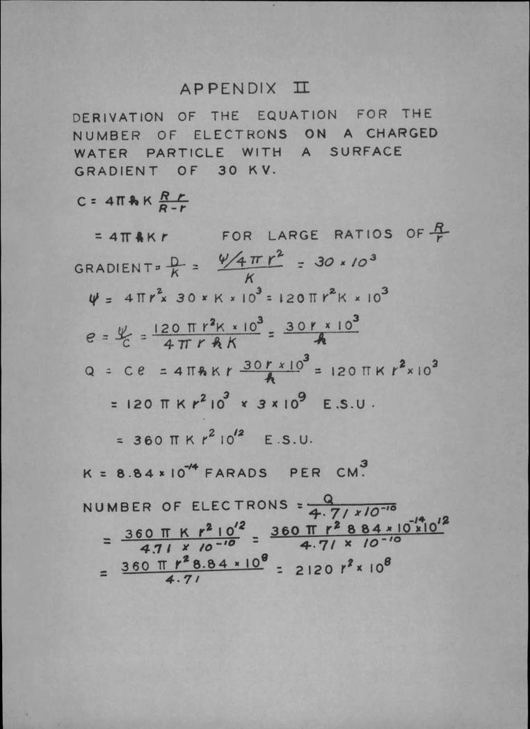
APPENDIX U DERIVATION OF THE EQUATION FOR THE
NUMBER OF ELECTRONS ON A CHARGED
WATER PARTICLE WITH A SURFACE GRADIENT OF 30 KV.
C: 4flt 4Tr4Kr FOR LARGE RATIOS OF*
GRADIENT Y/*rrr - -
K
4' 4TTrx 30 1K x ICY': 12011 V2R x Q3
e'
I2orrr2KxIo33orxIo3 4.7rrK - -A
Q ce 4flKr 3OrxIo3_ ______- - 120 TT( r2xI0
= 120 ir K r2 IO 3 x I0 E .S.0
360 ii K r2 i12 E s. U.
K 8.4 FARADS PER CM3
NUMBER OF ELECTRONS =- 4... 7/ i-'°
-14 ¡2
- 360 lT K r2 I
o12 360 lT r2 B 84 IO I0 -
411 X /O-'° 4.7/ X /0-lo
360 lT rZB.4 i 2120 r2X loo 4.7/ -