an investigation on a solar chimney modela solar chimney system (scs) is a solar thermal power plant...
TRANSCRIPT

JAUES, 14, 51, 2019 485
Journal Of Al-Azhar University Engineering Sector
Vol. 14, No. 51, April, 2019, 485-494
AN INVESTIGATION ON A SOLAR CHIMNEY MODEL
El-Adel A. Elkady , Mohamed A. Halawa Mostafa A. Mohamed and Mohamed I. Younes
Mechanical Engineering Department, Al-Azhar University
ABSTRACT A solar chimney system (SCS) is a solar thermal power plant utilizing a combination of solar air collector and central updraft tube to generate a solar induced convective flow which drives pressure staged turbines to generate electricity. In the present work, an experimental set-up model at the mechanical engineering department of Al-Azhar University was erected. Two geometrical parameters (chimney height, H and collector inlet height, h) have been investigated. The model collector radius, R is fixed at 1 m. The chimney diameter, d is fixed at 0.2 m and its height, H was varied from 2 m to 4 m. The collector inlet height, h was varied from 0.04 m to 0.08 m. Air velocity and temperature variation with time at chimney inlet have been measured as well as in canopy. The results show that the collector inlet height, h of 0.04 m and the chimney height, H of 4 m providing an optimum configuration for the constructed solar chimney model. The velocity and temperature profiles in the chimney was modeled by CFD analysis based on the same model dimensions. The CFD simulation was compared with the experimental data of the solar chimney model and a good agreement is noticed. Key words: Solar Chimney, Canopy, Greenhouse effect, Wind turbines.
:ملخص
محطات تولید الطاقة باستخدام المدخنة الشمسیة فیھا تستخدم الطاقة الشمسیة في تسخین الھواء داخل المجمع مما یحدث فرق في األبعاد . النتاج الكھرباءھوائیة عنھ فرق في الضغط یستخدم في تشغیل تربیناتدرجات الحرارة بین داخل المدخنة وخارجھا فینتج
تم عمل دراسة معملیة علي نموذج للمدخنة الشمسیة تم . الھندسیة الخاصة بالمحطة تعتبر من اھم العوامل المؤثرة علي أداء المحطة المطلوبة ورسم منحنیات تغیر السرعة ودرجات الحرارة مع تم إجراء القیاسات. إنشاؤه بقسم الھندسة المیكانیكیة بجامعة االزھر
.تم عمل محاكاة للنموذج وتم عمل مقارنة بین القیاسات المعملیة وقیاسات نموذج المحاكاة فوجد بینھم توافق جید. الزمن
INTRODUCTION Due to depletion of fossil fuels, global warming, continuing fuel price rise, the existing sources of conventional energy may not be adequate to meet the ever increasing energy demands. Untiring efforts have been made by the scientists and engineers in exploring the possibilities of harnessing energy from several non-conventional energy sources (solar, biomass, tidal, hydrogen, wind and geothermal energy) which they are seen as possible solution to the growing energy challenges [1]. In the last decades, solar chimney has been taken a great attention from researchers [2]. The main advantages of solar chimney system (SCS) are the low initial and maintenance cost (with respect to the other solar technologies), the simplicity of operation and the durability of the system [3]. The solar chimney power plant (SCPP) as shown in Fig.1 consists of: A greenhouse roof collector usually made of plastic sheet or glass plate. The collector worked as one-way valve which traps the solar energy and elevates the air temperature. Updraft chimney that is located at the center of the collector is used to vent and direct the hot air through the wind turbine. The wind turbine is used to convert the air kinetic energy into mechanical energy [4], [5]. Jörg Schlaich [6], [7] in 1981/82 constructed an experimental plant with a peak output of 50 kW in Manzanares. He examined the influence of individual components on the plant’s output and efficiency through field measurements. Pasumarthi and Sherif [8] developed a

AN INVESTIGATION ON A SOLAR CHIMNEY MODEL
JAUES, 14, 51, 2019 JAUES, 14, 51, 2019 486
mathematical model intended to have a capability to estimate the temperature and the power output of solar chimneys as well as to examine the effect of various ambient conditions and structural dimensions on the power output. Kröger and Buys [9] present a detailed plant analysis with a transient collector to predict the maximum power for a one year operational cycle. Padki and Sherif [10] also studied the effect of geometrical parameters on chimney performance. M. Kaltschmitt, [11] et al designed and built pilot solar chimney to investigate the temperature field as well as to examine the effect of time through the day on the temperature field. Zuo. I , et al [12] constructed comparison experimental models with different chimney structural parameters for the solar chimney power generation system integrated with seawater desalination. Alibakhsh and Mehran, et [13] al provided an analytical and numerical study for geometrical optimizing of a solar chimney prototype at University of Tehran. Ahmed Ayadi , et al [14] studied the characteristics of a solar chimney power plant using numerical and experimental methods. As a result, they provided that the collector roof height is very effective on the optimization of the solar chimney power plant. The objective of the present work is to study the effect of geometrical parameters on the velocity and temperature of air at chimney inlet of a solar chimney power plant (SCP) model. Tow geometrical parameters (chimney height, H and collector inlet height, h) were studied to fix the conditions of maximum velocity at chimney inlet which create maximum power output. 1. EXPERIMENTAL SET-UP
1.1. Solar Chimney Model
A solar chimney model is constructed in small scale in mechanical engineering department of Al-Azhar University in Cairo. The experimental set-up consisted of the chimney and the collector. The chimney is constructed from gray PVC pipe of 5 mm thickness each pipe 1 m length with inner diameter d= 0.2 m which connected to gather with a gray PVC collar to form the different heights of the chimney used in this study. Four 5mm diameter galvanized steel wires ware used to adjust the chimney vertically. The Collector frame is made from steel of radius R =1 m and thickness 10 mm supported by 4 adjustable supports were putted inside the concrete used to adjust the collector inlet height, h. At the center of the collector frame a steel pipe with 0.21 m inner diameter was used as a base for the chimney. A rubber tape is used as a sealant for the connection between steel pipe and PVC chimney. The Collector cover is made from 6mm thickness transparent glass flat plate with diameter of 2 m that was mounted on the collector frame. The glass acts as a one-way energy valve and it was used because of its reasonable price. A combination of chipboard wood with thickness 20 mm and black steel sheet metal of thickness 1mm are used as the collector absorber. The black steel sheets are used to increase the absorptivity of the system and also for rapid start of the test rig. The chipboard wood is used as a thermal insulator to prevent the heat leakage to the ground. The main components of the solar chimney test rig are illustrated in Fig.1. 1.2. Experimental Measurements
Experimental data is based on the measurement of the temperature inside the collector and chimney inlet as well as velocity measurement in chimney inlet. Temperature is assumed to be symmetrical along collector diameter [14], [15]. Twenty calibrated thermocouples type T (Copper/Constantan) were used. Fifteen thermocouples were fitted across one side of the collector and the other five were fitted inside the chimney a little above the chimney inlet. A data logger was used to log the temperature data which was interfaced to a Windows XP laptop and then saved in a Microsoft Excel file. A hot wire anemometer used to measure the velocity at five points in the chimney inlet then the average velocity was obtained.

AN INVESTIGATION ON A SOLAR CHIMNEY MODEL
JAUES, 14, 51, 2019 JAUES, 14, 51, 2019 485
Fig.1: Schematic diagram of solar chimney test rig

AN INVESTIGATION ON A SOLAR CHIMNEY MODEL
JAUES, 14, 51, 2019 486
2. Theoretical Model A two-dimensional geometrical model of asolar chimney has been developed in a design modular associated with ANSYS workbench. Since the problem is axi-symmetrical, the 2D model is used and simple meshing structure is invoked. The model geometry was designed with the same actual dimensions of the experimental test rig. The theoretical model was carried out for a chimney height H= 4 m and collector inlet height, h = 0.04 m at 1:00 pm (13:00). The model has been meshed and the mesh size is also refined at the chimney inlet, the collector, and absorber surface for improving the results at edges, and capturing the details at that planes. 2.1. Governing Equation
The numerical model for the study of fluid dynamics problems was based on the fundamental continuity, Navier-Stokes and energy equations as following. Continuity equation:
Navier-stokes equations:
Energy equation:
ρcp
2.2. Boundary Conditions
Boundary conditions assumed known as inlet pressure for collector inlet surface, outlet pressure for chimney outlet, and insulated stationary wall for chimney wall. The collector surface is considered as a semi-transparent wall. The chimney centerline is chosen as the symmetry axis. Table 1 shows the boundary conditions that have been applied to the theoretical model. Table 1: Boundary conditions.
Surface Type Value Collector inlet Inlet pressure ∆p = 0 T = Tamb
Chimney outlet Outlet pressure ∆p = 0 T = Tamb
Chimney wall Insulated stationary wall q = 0 W/m2 Collector Semi-transparent wall q = 800 W/m2
3 Results and Discussions
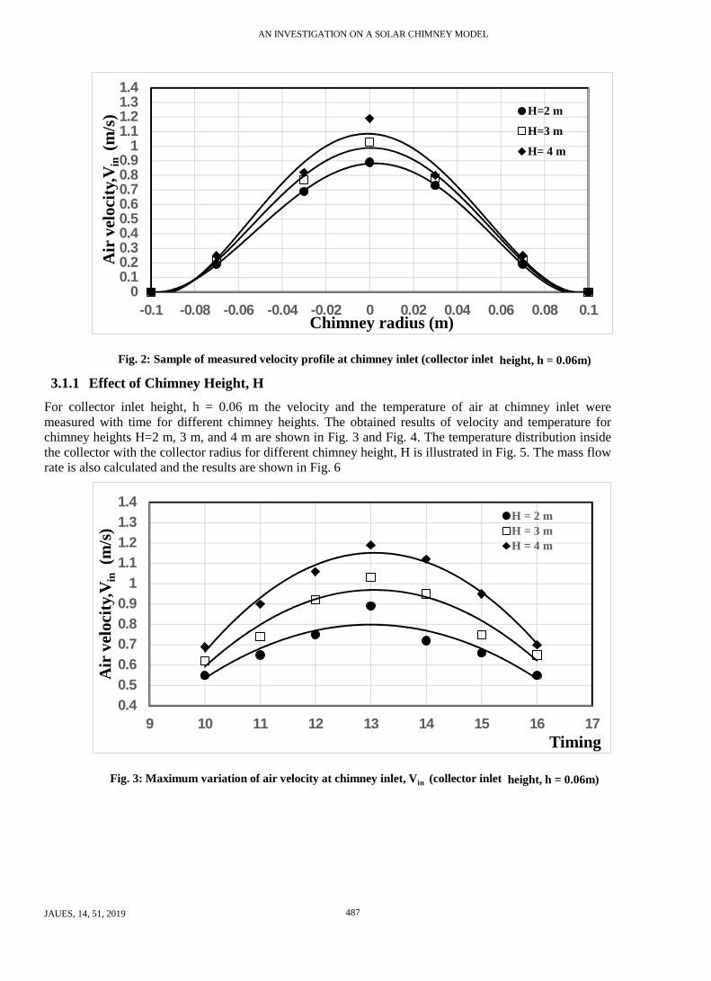
3.1 Experimental Results All experimental results have been taken in August 2018 where the climatic conditions were nearly unchanged. Fig.2 shows a sample of measured velocity profile at chimney inlet for collector inlet height h=0.06 m and different chimney height, H. It is noticed from the figure that the maximum velocity occurs at the axis of symmetry of the chimney. The velocity profile as shown is parabola curve which mean that there is no back flow through the chimney.
AN INVESTIGATION ON A SOLAR CHIMNEY MODEL
JAUES, 14, 51, 2019 487
00.10.20.30.40.50.60.70.80.9
11.11.21.31.4
-0.1 -0.08 -0.06 -0.04 -0.02 0 0.02 0.04 0.06 0.08 0.1
Air
vel
ocity
,Vin
(m
/s)
Chimney radius (m)
H=2 m
H=3 m
H= 4 m
Fig. 2: Sample of measured velocity profile at chimney inlet (collector inlet height, h = 0.06m)
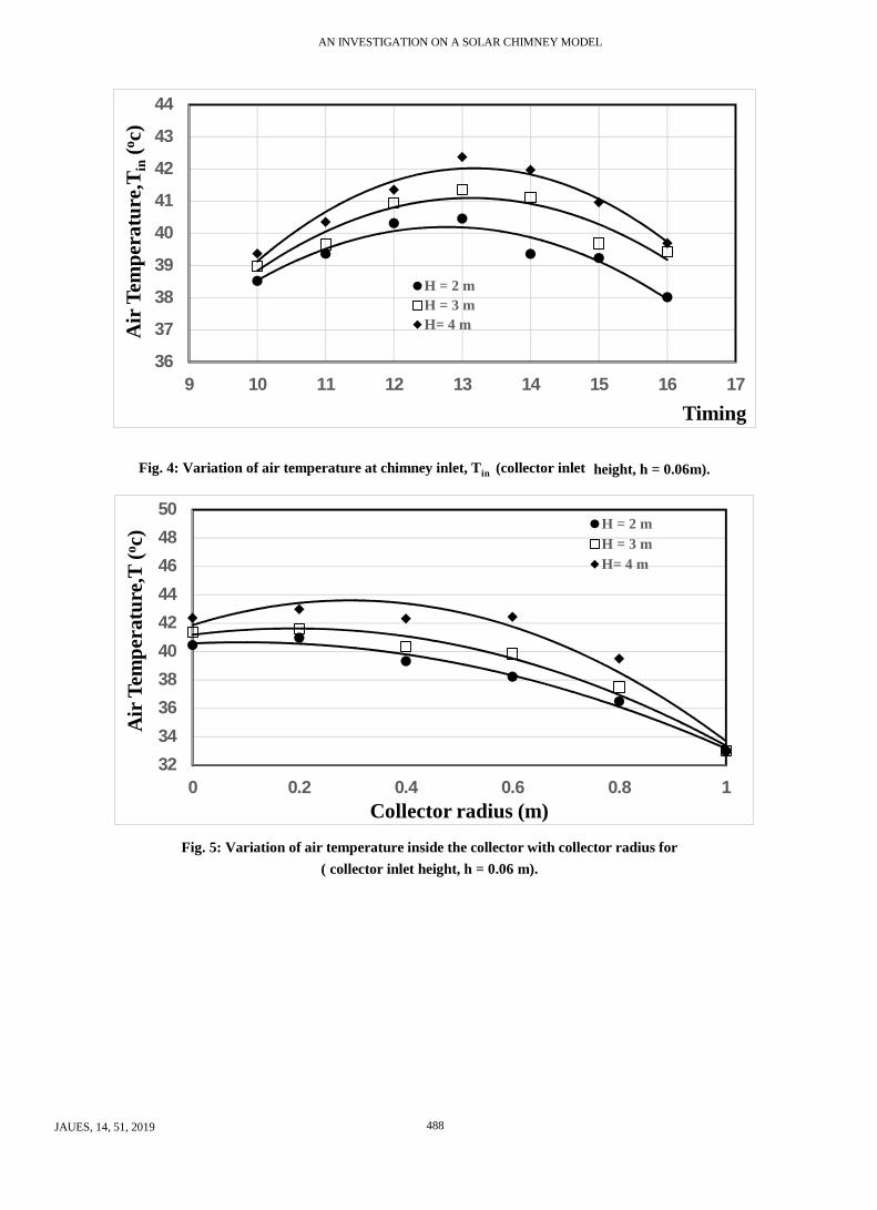
3.1.1 Effect of Chimney Height, H For collector inlet height, h = 0.06 m the velocity and the temperature of air at chimney inlet were measured with time for different chimney heights. The obtained results of velocity and temperature for chimney heights H=2 m, 3 m, and 4 m are shown in Fig. 3 and Fig. 4. The temperature distribution inside the collector with the collector radius for different chimney height, H is illustrated in Fig. 5. The mass flow rate is also calculated and the results are shown in Fig. 6
0.40.50.60.70.80.9
11.11.21.31.4
9 10 11 12 13 14 15 16 17
Air
vel
ocity
,Vin
(m/s
)
Timing
H = 2 mH = 3 mH = 4 m
Fig. 3: Maximum variation of air velocity at chimney inlet, Vin (collector inlet height, h = 0.06m)
AN INVESTIGATION ON A SOLAR CHIMNEY MODEL
JAUES, 14, 51, 2019 488
36
37
38
39
40
41
42
43
44
9 10 11 12 13 14 15 16 17
Air
Tem
pera
ture
,Tin
(o c)
Timing
H = 2 mH = 3 mH= 4 m
Fig. 4: Variation of air temperature at chimney inlet, Tin (collector inlet height, h = 0.06m).
32
34
36
38
40
42
44
46
48
50
0 0.2 0.4 0.6 0.8 1
Air
Tem
pera
ture
,T (o c
)
Collector radius (m)
H = 2 mH = 3 mH= 4 m
Fig. 5: Variation of air temperature inside the collector with collector radius for ( collector inlet height, h = 0.06 m).

AN INVESTIGATION ON A SOLAR CHIMNEY MODEL
JAUES, 14, 51, 2019 489
1
1.5
2
2.5
3
3.5
4
4.5
5
9 10 11 12 13 14 15 16 17
Mas
s flo
w ra
te, m
. in(k
g/s)
x10
-3
Timing
H = 2 mH = 3 mH = 4 m
Fig. 6: Variation of mass flow rate at chimney inlet, m.in ( collector inlet height, h = 0.06 m).
It is evident from the results that are shown in Fig. 3 that the air velocity at chimney inlet, Vin is increasing with the chimney height, H for the same other conditions. The air velocity at chimney inlet, Vin at time 13:0 pm is observed to be about 0.89 m/s at chimney height, H = 2 m and is increased to be about 1.03 and 1.19 m/s at chimney height, H = 3 and 4 m, respectively. Fig. 4 shows that the air temperature at chimney inlet, Tin is increasing with the chimney height, H for the same other conditions. The maximum air temperature at chimney inlet, Tin at time 13:0 pm is observed to be about 40.5 oC at chimney height, H = 2 m and is increased to be about 41.1, and 42.4 oC at chimney height, H = 3 and 4 m, respectively. For all chimney height, H = 2, 4, and 6 m, the velocity and the temperature are noticed to be maximum at time 13:00 pm because the maximum solar intensity is achieved at that time then causing increase in temperature and velocity inside the collector and chimney. Also, they are noticed that the velocity and the temperature are increasing with chimney height, H because of the draft force. Where with increasing chimney height, H the pressure difference between the chimney inlet and exit is also increasing causing increase in draft force then the air velocity and temperature. Also, it is evident from Fig. 5 that the air temperature, T inside the collector rapidly increases at collector inlet then slowly increases through the collector and then decreases again near the central axis of the chimney. The air temperature inside the collector at inlet is nearly the same of the ambient temperature then begin increases through the collector because of the gained solar energy which increases in the radial direction towards the chimney axis. It is thought that the air temperature near the chimney axis decreases because of the sharp edge between the collector and the chimney which may be causes stagnant region causes this decrease.Fig.6 shows the variation of mass flow rate, m. with time for collector inlet height, h = 0.06 m and chimney height, H =2,3and 4 m. The maximum mass flow rate at chimney inlet, m.in is observed at time 13:0 pm with value of 3.63x10 -3 kg/s at chimney height, H = 2 m and is increased to be about 3.96 and 4.17x10 -3 kg/s at chimney height, H = 3 and 4 m, respectively. It is noticed that the graph of the mass flow rate with time is nearly the same as the graph of the velocity with time. The mass flow rate is function of the cross section area which is unchanged, the velocity which is varied, and the air density which is slightly varied “nearly unchanged’. Finally, the mas flow rate is nearly function of velocity only then the two graphs are similar. According to the above results, the best chimney height, H for this model is 4 m. But in fact, for each SCPP there is an optimum chimney height, H corresponding to its collector radius, R.
AN INVESTIGATION ON A SOLAR CHIMNEY MODEL
JAUES, 14, 51, 2019 490
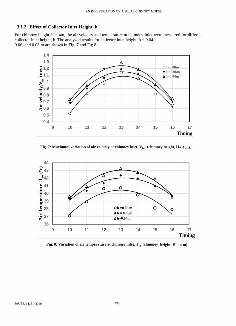
3.1.2 Effect of Collector Inlet Height, h For chimney height H = 4m, the air velocity and temperature at chimney inlet were measured for different collector inlet height, h. The analyzed results for collector inlet height, h = 0.04, 0.06, and 0.08 m are shown in Fig. 7 and Fig 8
0.40.50.60.70.80.9
11.11.21.31.4
9 10 11 12 13 14 15 16 17
Air
vel
ocity
,Vin
(m
/s)
Timing
h=0.08mh =0.06mh=0.04m
Fig. 7: Maximum variation of air velocity at chimney inlet, Vin (chimney height, H= 4 m).
36
37
38
39
40
41
42
43
44
9 10 11 12 13 14 15 16 17
Air
Tem
pera
ture
,Tin
(o c)
Timing
h =0.08 mh = 0.06mh=0.04m
Fig. 8: Variation of air temperature at chimney inlet, Tin (chimney height, H = 4 m)

AN INVESTIGATION ON A SOLAR CHIMNEY MODEL
JAUES, 14, 51, 2019 491
32343638404244464850
0 0.2 0.4 0.6 0.8 1
Air
Tem
pera
ture
,T (o c
)
Collector radius (m)
h=0.08 mh =0.06mh=0.04m
Fig. 9: Variation of air temperature inside the collector with collector radius ( chimney height H = 4 m)
1
1.5
2
2.5
3
3.5
4
4.5
5
9 10 11 12 13 14 15 16 17
Mas
s flo
w ra
te, m
. in(k
g/s)
x10
-3
Timing
h=0.08mh =0.06mh=0.04m
Fig. 10: Variation of mass flow rate at chimney inlet, m.
in (chimney height, H = 4 m)
As shown in Fig. 7,8 at chimney height, H=4 m, the air velocity and temperature at chimney inlet, Vin, Tin are decreasing with increasing the collector inlet height, h for the same other conditions. It is noticed that the two graphs have the same trend where the maximum air velocity and temperature at chimney inlet were occurred at time 13:0 pm as before because of the same previous reasons. It is observed from Fig. 6 that the velocity is about 1.29 m/s at collector inlet height, h = 0.04 m and is decreased to be about 1.19 m/s, and 1.14 m/s at collector inlet height, h = 0.06 m and 0.08 m respectively. Fig. 7 shows that the maximum air temperature at chimney inlet, Tin is observed to be about 43.3 oC at collector inlet height, h = 0.04 m and is decreased to be about 42.4 oC and 40.7 oC at collector inlet height, h = 0.06 m and 0.08 m respectively. According to the above results, the best collector inlet height, h is 0.04 m. Also, it is evident from Fig. 9 that at collector inlet height, h = 0.04 m, the air temperature, T increases through the

AN INVESTIGATION ON A SOLAR CHIMNEY MODEL
JAUES, 14, 51, 2019 492
collector until nearly the middle then decreases until reaching to the chimney entrance. But for collector inlet height, h = 0.06 and 0.08 m, the air temperature, T rapidly increases at collector inlet then slowly increases through the collector until reaching to the chimney entrance. At small collector inlet height, h = 0.04 m, wind has no or low effect on the air inside the collector as the inlet is nearly closed, this make the change of air temperature inside collector near the entrance is high. Fig.10 shows the variation of mass flow rate at chimney inlet with time for chimney height, H=4 m and collector inlet height, h = 0.08, 0.06 and 0.04 m. The maximum mass flow rate at chimney inlet, m. observed at time 13:0pm with value of 4.05x10 -3 kg/s at h = 0.08 m and is increased to be about 4.17x10 -3 and 4.65x10 -3 at, h = 0.06 and 0.04 m, respectively. According to the above results the maximum velocity of air at chimney inlet is reduced with increasing the collector inlet height, h. It is noticed that, the higher temperature difference is found, the higher air velocity is formed, the higher mass flow rate is found, and thus the higher power is generated.
3.2 Comparison Between Experimental and Theoretical Results In this section velocity contour and velocity profile for chimney height H = 4 m, chimney diameter, d=0.2 m ,and collector inlet height, h = 0.04 m are presented and discussed. The simulation and experimental ambient conditions were assumed to be the same. The simulation results were validated with the experimental data. Figure 11 shows distribution of velocity and temperature in the whole volume of the solar chimney. According to these contours the maximum velocity is observed at chimney inlet with magnitude 1.35 m/s where the measured experimental velocity for this case was 1.29m/s. It is noticed that, the simulation velocity is larger than experimental one by about 4.7%. Also, according to these contours the temperature at chimney inlet is about 44.6 oC but the experimental one is 43.3 oC. Also, the simulation temperature is noticed to be larger than experimental one by about 3%.
Fig. 11: Velocity and temperature contours inside collector
(chimney height, H = 4 m and collector inlet height, h = 0.04 m) Figure 12 presents a comparison between the experimental and the simulation profile of velocity at chimney inlet. As shown in figure one can see a fluctuation in velocity near the chimney wall due to sharp edge connection between chimney and collector. Changing this sharp connection to another round shape will decrease the fluctuation and make the graph smooth. Figure 13 presents a comparison between experimental and simulation profile of temperature inside the collector. According to this comparison a good agreement has been observed. Hence, the simulation model can be used to predict characteristics of air flow in the solar chimney.

AN INVESTIGATION ON A SOLAR CHIMNEY MODEL
JAUES, 14, 51, 2019 493
00.10.20.30.40.50.60.70.80.9
11.11.21.31.4
-0.1 -0.08 -0.06 -0.04 -0.02 0 0.02 0.04 0.06 0.08 0.1
Air v
elocit
y,Vin
(m
/s)
Chimney radius (m)
Poly. (Simulation results)
Poly. (experimental results )
Fig. 12 Comparison between experimental and theoretical results of air velocity at chimney inlet
32343638404244464850
0 0.2 0.4 0.6 0.8 1Air
Tem
pera
ture
,T (o c
)
Collector radius (m)
Poly. (Simulation results)
Poly. (Experimental results)
Fig. 13 Comparison between experimental and theoretical results of air temperature inside the
collector CONCLUSION
The experimental test rig has been used to analyze the effects of geometrical parameters on a solar chimney model. From the previous analysis of the experimental results, it is found that the increasing of chimney height, H will increase the air velocity which in turn increase the output power. Also, it is noticed that the decreasing of collector inlet height, h causes also increase in the air velocity which increase air flow rate and output power. The theoretical results were validated with the experimental results of the solar chimney prototype and they give a good agreement.
NOMENCLATURE Cp specific heat, J /kg.K
D collector diameter, m d chimney diameter, m
g gravity acceleration, m /s2
H chimney height, m h collector inlet height, m m. mass flow rate in chimney, kg/ s P pressure, Pa Δp Pressure drop, Pa q Solar heat flux, w/m2 R collector radius, m T air temperature, oC

AN INVESTIGATION ON A SOLAR CHIMNEY MODEL
JAUES, 14, 51, 2019 494
V Air velocity in axial direction, m/ s Subscripts amb ambient condition in chimney inlet Greek symbols ρ density, kg /m3 μ viscosity , Pa.s
REFERENCES:
[1] R. K. Rajput, "Power System Engineering", Firewall Media, pp.198, 2006. [2] Peng-hua Guo, Jing-yin Li, and Yuan Wang, "Annual performance analysis of the solar
chimney power plant in Sinkiang, China," Elsevier, Energy Conversion and Management 87, p. 392-399, 2014.
[3] Mohammad O. Hamdan, "Analysis of solar chimney power plant utilizing chimney discrete model" Renewable Energy, Elsevier, 56 - 50 ,2013.
[4] E. Gholamalizadeh and S.H. Mansouri,, "A comprehensive approach to design and improve a solar chimney power plant :A special case – Kerman project" Elsevier , Applied Energy 102, p. 975-982, 2013.
[5] Li JY, Guo PH, Wang Y. “Effects of collector radius and chimney height on power output of a solar chimney power plant with turbine,”. Renew Energy,47:21–8, 2012.
[6] Jorg Schlaich, Rudolf Bergermann, "Design of Commercial Solar Updraft Tower Systems- Utilization of Solar Induced Convective Flows for Power Generation," Journal of Solar Energy Engineering, Volume, 127, Pages 117, 2005.
[7] Zhou, X., “Novel Concept for Producing Energy I ntegrating a Solar Collector with a Man Made Mountain Hollow,”Energy Conversion and Management, 50, 3, pp. 847-854, 2009.
[8] Pasumarthi, N. and S.A. Sherif, "Experimental And Theoritical Performance Of a Demonstartion Solar Chimeny Model",ǁ in Int. J. Energy Res., 22,277Ð288 (1998 1998, Florida, USA) .
[9] A. J. Gannon, "Solar chimney turbine performance", PhD, Stellenbosch: University of Stellenbosch, 2002.
[10] Padki MM, Sherif SA." A mathematical model for solar chimneys". In:Proceedings of the international renewable energy conference in faculty of engineering and technology. University of Jordan; 1992.
[11] M. Kaltschmitt, W. Streicher, and A. Wiese, "Towers of Power : The Solar Updraft Tower," Renewable energy: technology, economics, and environment , Springer, 2007.
[12] Zuo L, Zheng Y, Li Z, Sha Y. The influence of chiimney structural parameters on the solar chimneys integrated with seawater desalination. In: Sustainable power generation and supply (SUPERGEN 2012). Hangzhou, China; p.1–5, 2012.
[13] Alibakhsh Kasaeian, Mehran Ghalamchi, and Mehrdad Ghalamchi, "Simulation and optimization of geometric parameters of a solar chimney in Tehran- Tehran," Elsevier ,Energy Conversion and Management 83, p. 28-34, 2014.
[14] Ahmed Ayadi, Abdallah Bouabidi, Zied Driss andMohamed Salah Abid, "Experimental and numerical analysis of the collector roof height effect on the solar chimney performance," Elsevier ,Renewable Energy, 2017.
[15] A. Al-Dabbas,"A performance analysis of solar chimney thermal power systems," Thermal Science, vol. 15, no 3, pp. 619-642,2011.