an isolated multiport dc–dc converter for simultaneous
TRANSCRIPT

University of Nebraska - LincolnDigitalCommons@University of Nebraska - LincolnFaculty Publications from the Department ofElectrical and Computer Engineering Electrical & Computer Engineering, Department of
2014
An Isolated Multiport DC–DC Converter forSimultaneous Power Management of MultipleDifferent Renewable Energy SourcesJianwu ZengUniversity of Nebraska-Lincoln, [email protected]
Wei QiaoUniversity of Nebraska–Lincoln, [email protected]
Liyan QuUniversity of Nebraska-Lincoln, [email protected]
Yanping JiaoUniversity of Nebraska-Lincoln, [email protected]
Follow this and additional works at: http://digitalcommons.unl.edu/electricalengineeringfacpub
Part of the Computer Engineering Commons, and the Electrical and Computer EngineeringCommons
This Article is brought to you for free and open access by the Electrical & Computer Engineering, Department of at DigitalCommons@University ofNebraska - Lincoln. It has been accepted for inclusion in Faculty Publications from the Department of Electrical and Computer Engineering by anauthorized administrator of DigitalCommons@University of Nebraska - Lincoln.
Zeng, Jianwu; Qiao, Wei; Qu, Liyan; and Jiao, Yanping, "An Isolated Multiport DC–DC Converter for Simultaneous PowerManagement of Multiple Different Renewable Energy Sources" (2014). Faculty Publications from the Department of Electrical andComputer Engineering. 327.http://digitalcommons.unl.edu/electricalengineeringfacpub/327
70 IEEE JOURNAL OF EMERGING AND SELECTED TOPICS IN POWER ELECTRONICS, VOL. 2, NO. 1, MARCH 2014
An Isolated Multiport DC–DC Converter forSimultaneous Power Management of Multiple
Different Renewable Energy SourcesJianwu Zeng, Student Member, IEEE, Wei Qiao, Senior Member, IEEE,
Liyan Qu, Member, IEEE, and Yanping Jiao, Student Member, IEEE
Abstract— This paper proposes a new isolated multiportdc–dc converter for simultaneous power management of multiplerenewable energy sources, which can be of different typesand capacities. The proposed dc–dc converter only uses onecontrollable switch in each port to which a source is connected.Therefore, it has the advantages of simple topology and minimumnumber of power switches. A general topology of the proposedconverter is first introduced. Its principle and operation are thenanalyzed. The proposed converter is applied for simultaneousmaximum power point tracking (MPPT) control of a wind/solarhybrid generation system consisting of one wind turbinegenerator (WTG) and two different photovoltaic (PV) panels. Theexperimental results are provided to validate the effectiveness ofusing the proposed converter to achieve MPPT simultaneouslyfor the WTG and both PV panels.
Index Terms— Isolated dc–dc converter, maximum powerpoint tracking (MPPT), multiport converter, power management,renewable energy, solar energy, wind energy.
I. INTRODUCTION
IN RECENT years, there has been a growing interest ingenerating electricity from distributed renewable energy
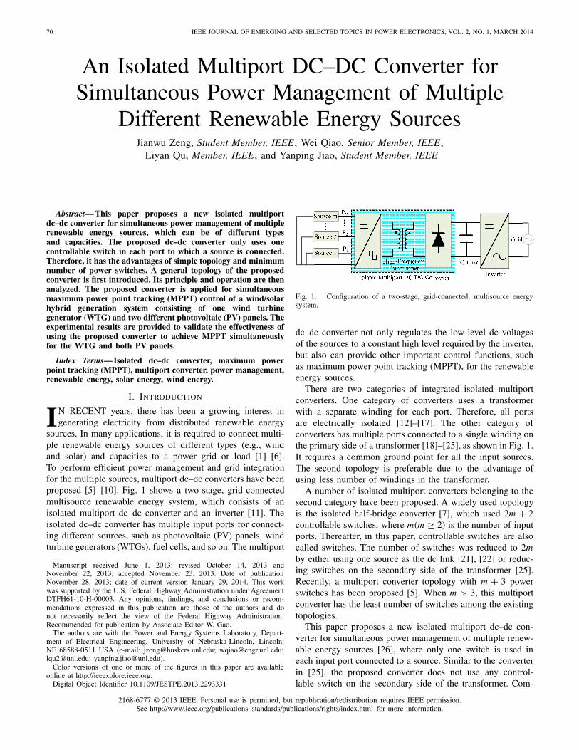
sources. In many applications, it is required to connect multi-ple renewable energy sources of different types (e.g., windand solar) and capacities to a power grid or load [1]–[6].To perform efficient power management and grid integrationfor the multiple sources, multiport dc–dc converters have beenproposed [5]–[10]. Fig. 1 shows a two-stage, grid-connectedmultisource renewable energy system, which consists of anisolated multiport dc–dc converter and an inverter [11]. Theisolated dc–dc converter has multiple input ports for connect-ing different sources, such as photovoltaic (PV) panels, windturbine generators (WTGs), fuel cells, and so on. The multiport
Manuscript received June 1, 2013; revised October 14, 2013 andNovember 22, 2013; accepted November 23, 2013. Date of publicationNovember 28, 2013; date of current version January 29, 2014. This workwas supported by the U.S. Federal Highway Administration under AgreementDTFH61-10-H-00003. Any opinions, findings, and conclusions or recom-mendations expressed in this publication are those of the authors and donot necessarily reflect the view of the Federal Highway Administration.Recommended for publication by Associate Editor W. Gao.
The authors are with the Power and Energy Systems Laboratory, Depart-ment of Electrical Engineering, University of Nebraska-Lincoln, Lincoln,NE 68588-0511 USA (e-mail: [email protected]; [email protected];[email protected]; [email protected]).
Color versions of one or more of the figures in this paper are availableonline at http://ieeexplore.ieee.org.
Digital Object Identifier 10.1109/JESTPE.2013.2293331
Fig. 1. Configuration of a two-stage, grid-connected, multisource energysystem.
dc–dc converter not only regulates the low-level dc voltagesof the sources to a constant high level required by the inverter,but also can provide other important control functions, suchas maximum power point tracking (MPPT), for the renewableenergy sources.
There are two categories of integrated isolated multiportconverters. One category of converters uses a transformerwith a separate winding for each port. Therefore, all portsare electrically isolated [12]–[17]. The other category ofconverters has multiple ports connected to a single winding onthe primary side of a transformer [18]–[25], as shown in Fig. 1.It requires a common ground point for all the input sources.The second topology is preferable due to the advantage ofusing less number of windings in the transformer.
A number of isolated multiport converters belonging to thesecond category have been proposed. A widely used topologyis the isolated half-bridge converter [7], which used 2m + 2controllable switches, where m(m ≥ 2) is the number of inputports. Thereafter, in this paper, controllable switches are alsocalled switches. The number of switches was reduced to 2mby either using one source as the dc link [21], [22] or reduc-ing switches on the secondary side of the transformer [25].Recently, a multiport converter topology with m + 3 powerswitches has been proposed [5]. When m > 3, this multiportconverter has the least number of switches among the existingtopologies.
This paper proposes a new isolated multiport dc–dc con-verter for simultaneous power management of multiple renew-able energy sources [26], where only one switch is used ineach input port connected to a source. Similar to the converterin [25], the proposed converter does not use any control-lable switch on the secondary side of the transformer. Com-
2168-6777 © 2013 IEEE. Personal use is permitted, but republication/redistribution requires IEEE permission.See http://www.ieee.org/publications_standards/publications/rights/index.html for more information.

ZENG et al.: ISOLATED MULTIPORT DC–DC CONVERTER 71
Fig. 2. Topology of the proposed isolated multiport dc–dc converter.
pared with the existing multiport dc–dc converter topologies[18]–[25], the proposed converter has the least number ofswitches and thereby a lower cost.
The proposed converter is applied for power managementof a wind/solar hybrid generation system, which consists of aWTG and two different PV panels. Using a suitably designedperturbation and observation (P&O) MPPT algorithm, theWTG and PV panels can be controlled simultaneously toextract the maximum power from wind and sunlight, respec-tively, using the proposed converter.
This paper is organized as follows. The topology of the con-verter is introduced and the operating principle of the converteris analyzed in Section II. Section III discusses the designconsiderations for the proposed converter. In Section IV,the proposed converter is applied for simultaneous powermanagement of a wind/solar hybrid generation system. Theexperimental studies are carried out in Section V to testifythe effectiveness of the proposed isolated multiport dc–dcconverter for simultaneous MPPT control of the wind/solarhybrid generation system. Section VI summarizes this paperwith some concluding remarks.
II. PROPOSED ISOLATED MULTIPORT
DC–DC CONVERTER
Fig. 2 shows the circuit diagram of the proposed iso-lated multiport dc–dc converter. It consists of a low-voltage-side (LVS) circuit and a high-voltage-side (HVS) circuitconnected by a high-frequency transformer TX. The LVScircuit consists of m ports in parallel, one energy storagecapacitor Cs , and the primary winding of the transformer.Each port contains a controllable power switch, a power diode,and an inductor. The HVS circuit consists of the secondarywinding of the transformer connected to a full-bridge dioderectifier, and a low-frequency LC filter. The transformer’s turnratio is defined as n = Np /Ns , where Np and Ns are thenumbers of turns of the primary and secondary windings,respectively.
This converter has three operating modes: 1) all switches areon; 2) switch S1 is off while at least one of the other switchesis on; and 3) all switches are off. The equivalent circuits of theconverter in the three operating modes are shown in Fig. 3.Fig. 4 shows the steady-state waveforms of the converter in
Fig. 3. Equivalent circuits of the three operating modes of the proposedconverter. (a) Mode 1: all switches are on. (b) Mode 2: S1 is off and at leastone of the other switches is on. (c) Mode 3: all switches are off.
one switching period covering the three operating modes whenm = 3. To facilitate the explanation of the converter operation,the state-space equations for different modes are written in thefollowing form:
M · X = A · X + B (1)
where M = diag(L1, L2, . . . , Lm , Cs , L, C) is a (m + 3) ×(m + 3) diagonal matrix, X = [i1, i2, . . . , im, vcs, iL , vdc]T is

72 IEEE JOURNAL OF EMERGING AND SELECTED TOPICS IN POWER ELECTRONICS, VOL. 2, NO. 1, MARCH 2014
Fig. 4. Waveforms of the proposed converter when m = 3.
a (m + 3) × 1 state vector, A is the (m + 3) × (m + 3)coefficient matrix, and B is a (m + 3) × 1 vector containinginput signals and some state variables.
Mode 1: t ∈ [t0, t1] (see Fig. 4), during which all of theswitches are on and the inductors L1, . . . , Lm store the energyextracted from the sources; while the energy stored in thecapacitor Cs in the previous switching cycle is delivered tothe HVS through the diodes Ds2 and Ds4. The state-spaceequations can be described as follows:
M · X =⎡⎢⎢⎢⎢⎢⎢⎢⎢⎢⎢⎣
0 0 · · · 0 0 0 00 0 · · · 0 0 0 0...
.... . .
......
......
0 0 · · · 0 0 0 00 0 · · · 0 0 0 00 0 · · · 0 1/n 0 −10 0 · · · 0 0 1 −1/R
⎤⎥⎥⎥⎥⎥⎥⎥⎥⎥⎥⎦
· X +
⎡⎢⎢⎢⎢⎢⎢⎢⎢⎢⎢⎣
v1v2
...
vm
−i p
00
⎤⎥⎥⎥⎥⎥⎥⎥⎥⎥⎥⎦
(2)
Mode 2: t ∈ [t1, t3], during which S1 is off and at least oneswitch Sk (k = 2, . . . , or m) is on. Actually, there are 2m−1−1different scenarios in this mode depending on the states ofthe other (m − 2) switches S2, . . . , Sk−1, Sk+1, . . . , Sm . Onescenario is illustrated as an example, in which only oneswitch Sk is on and all other switches are off. The state-space
equations are
M · X =⎡⎢⎢⎢⎢⎢⎢⎢⎢⎢⎢⎢⎢⎢⎢⎢⎢⎣
0 · · · 0 0 0 · · · 0 −1 0 0...
. . ....
......
. . ....
......
...0 · · · 0 0 0 · · · 0 −1 0 00 · · · 0 0 0 · · · 0 0 0 00 · · · 0 0 0 · · · 0 −1 0 0...
. . ....
......
. . ....
......
...0 · · · 0 0 0 · · · 0 −1 0 01 · · · 1 0 1 · · · 1 0 0 00 · · · 0 0 0 · · · 0 0 0 −10 · · · 0 0 0 · · · 0 0 1 −1/R
⎤⎥⎥⎥⎥⎥⎥⎥⎥⎥⎥⎥⎥⎥⎥⎥⎥⎦
· X +
⎡⎢⎢⎢⎢⎢⎢⎢⎢⎢⎢⎢⎢⎢⎢⎢⎢⎣
v1 − vp...
vk−1 − vp
vk
vk+1 − vp...
vm
0vp/n
0
⎤⎥⎥⎥⎥⎥⎥⎥⎥⎥⎥⎥⎥⎥⎥⎥⎥⎦
(3)
Mode 3: t ∈ [t3, t4], during which all switches are off. Thestate-space equations are
M · X =
⎡⎢⎢⎢⎢⎢⎢⎢⎢⎢⎣
0 0 · · · 0 −1 0 00 0 · · · 0 −1 0 0...
.... . .
......
......
0 0 · · · 0 −1 0 01 1 · · · 1 0 0 00 0 · · · 0 0 0 −10 0 · · · 0 0 1 −1/R
⎤⎥⎥⎥⎥⎥⎥⎥⎥⎥⎦
· X +
⎡⎢⎢⎢⎢⎢⎢⎢⎢⎢⎣
v1 − vp
v2 − vp...
vm − vp
0vp/n
0
⎤⎥⎥⎥⎥⎥⎥⎥⎥⎥⎦
(4)
With (2)–(4), the average state-space model can be derivedas follows:
M · X =⎡⎢⎢⎢⎢⎢⎢⎢⎢⎢⎣
0 0 · · · 0 −(1 − d1) 0 00 0 · · · 0 −(1 − d2) 0 0...
.... . .
......
......
0 0 · · · 0 −(1 − dm) 0 0(1 − d1) (1 − d2) · · · (1 − dm) 0 0 0
0 0 · · · 0 d1/n 0 00 0 · · · 0 0 1 −1/R
⎤⎥⎥⎥⎥⎥⎥⎥⎥⎥⎦
·X
+
⎡⎢⎢⎢⎢⎢⎢⎢⎢⎢⎣
v1 − (1 − d1)vp
v2 − (1 − d2)vp...
vm − (1 − dm)vp
−d1 · i p
(1 − d1) · vp/n0
⎤⎥⎥⎥⎥⎥⎥⎥⎥⎥⎦
(5)
where dk (k = 1, . . . , m) is the duty cycle of the switch Sk .The equilibrium points can be calculated by setting all
time-derivative terms in (5) to be zero, then
Dk = 1 − (1 − D1) · Vk/V1 k = 2, . . . , m (6)
Ip− · D1 =m∑
k=1
Ik(1 − Dk) (7)
where Dk represents the steady-state value of dk and Vk isthe steady-state voltage of the kth input port of the converter.Equation (7) shows the power conservation law in the capac-itor Cs , where Ip−, as shown in Fig. 4, is the mean absolutevalue of i p when S1 is on, and Ik is the steady-state valuesof ik .

ZENG et al.: ISOLATED MULTIPORT DC–DC CONVERTER 73
III. DESIGN CONSIDERATIONS
To make multiple sources work effectively, the followingrequirement should be satisfied: the switch Sk (k = 2, . . . , m)should not be turned off before S1 is switched off; otherwise,Lk will continuously store energy through S1 even Sk is off,which is not desired. To meet this requirement, the followinginequality should be satisfied for the converter
min{d2, d3, . . . , dm} ≥ d1 (8)
Inequality (8) is met if the input voltage of Port 1 (P1) isthe largest, namely the following inequality is satisfied:
V1 ≥ max{V2, V3, . . . , Vm} (9)
where Vk is the output voltage of the kth source(k = 1, . . . , m). In practice, the renewable energy sourcewith the largest nominal output voltage will be connected toPort 1. A violation of (9) may lead to one of the followingtwo scenarios.
Scenario 1 (V1 = 0): If no power is available fromPort 1, (9) is no longer valid but (8) should still be satisfied.In this scenario, the duty cycle of the switch S1 is set to bea constant value such that (8) is satisfied, e.g., d1 = 0.4, andthe function of the switch S1 is to change the direction of thecurrent i p flowing through the transformer. Specifically, whenS1 is off, the current i p flows from the other sources to thetransformer to charge the capacitor Cs . When S1 is on, thecapacitor Cs discharges so that the direction of the current i p
reverses.Scenario 2 (0 < V1 < max{V2, V3, . . . , Vm}): If the maxi-
mum power that can be generated by the renewable energysource at Port 1 is low such that (9) cannot be satisfied,(8) should still be satisfied. In this scenario, the duty cycle ofthe switch S1 will be increased to a predefined maximum value(e.g., 0.4) by the MPPT controller such that (8) is satisfied, andthe function of the switch S1 is the same as that in Scenario 1.In this scenario, the power generated by the renewable energysource connected to Port 1 might be less than the maximumpower that can be generated by the source. However, thedifference between the generated and the maximum power atPort 1 is small because the maximum available power at Port 1is usually very low in this scenario.
It should be noted that in the aforementioned two scenarios,the sources connected to other ports (i.e., Ports 2–m) canstill be controlled simultaneously and independently in theMPPT mode by appropriately controlling the duty cycles of thecorresponding switches. Therefore, in Scenario 1, the powermanagement of all the ports is still independent. In Scenario 2,the power management of Port 1 is not independent, whichslightly affects the power generated from Port 1. However,Scenario 2 can be avoided by connecting a boost type voltageregulator between the source and Port 1 [27] so that (9) isalways satisfied.
The parameters of the components of the converter needto be properly designed. These include the transformer turnratio n, inductances Lk (k = 1, . . . , m) and L, capacitances Ck
(k = 1, . . . , m) and CS , and the switches Sk (k = 1, . . . , m).The turn ratio of the transformer is designed based on the
output voltage Vdc and the source voltage V1 of Port 1 [27]
n = 2 · V1 · D1/Vdc. (10)
The design of the inductance Lk (k = 1, . . . , m) is the sameas that in the dc–dc boost converter. When Sk is on, the voltageacross the inductor Lk is Vk , then
Vk = Lk�Ik
Dk · Tsk = 1, 2, . . . , m (11)
where �Ik is the desired current ripple of the inductor Lk andTs is the switching period. Therefore, the inductance can becalculated by the following formula:
Lk = Vk · Dk
fs · �Ikk = 1, 2, . . . , m (12)
where fs is the switching frequency of the converter. When S1is on, the voltage across the secondary inductor L is V1/n−Vdc,and therefore
L = (V1/n − Vdc) · D1 · Ts
�IL= V1 · (1 − 2D1) · D1
fs · n · �IL(13)
where �IL is the desired current ripple of the inductor L.Particularly, when D1 = 0.25, L achieves its peak value
Lmax = V1
8 fs · n · �IL. (14)
Then, �IL can be controlled within a certain value ifselecting L > Lmax.
In the steady state, the inductor current equals to the sourcecurrent in each input port, and the capacitor Ck (k = 1, . . . , m)provides the ripple current �Ik of the inductor
�Ik = Ck�vk
Dk · Tsk = 1, 2, . . . , m (15)
where �vk is the voltage ripple of Ck . Then
Ck = �Ik · Dk
fs · �vkk = 1, 2, . . . , m. (16)
Similarly, the capacitor C provides the extra current tobalance the ripple current �IL caused by the inductor L. Then,the capacitance C can be calculated from (16) with the use of�Ik = �IL , Dk = D1, and �vk = �vdc.
When Sk is off, the current flowing through Cs is increasedby Ik , then the capacitance Cs is determined as follows:
Cs =
m∑k=1
Ik(1 − Dk) · Ts
�vcs=
m∑k=1
Ik(1 − Dk)
fs · �vcs(17)
where �vcs is the voltage ripple of Cs .The peak voltage of the switch Sk (k = 2, . . . , m) is
Vk /(1 − Dk), which equals to V1/(1 – D1) according to (6).The peak current flowing through the switch Sk (k = 2, . . . , m)is Ik , which is less than that flowing through S1. When S1 ison, as shown in Fig. 3(a), the inductor L1 stores energy andthe capacitor Cs discharges, then the current flowing throughS1 becomes
IS1 = I1 + Ip− =I1 +
m∑k=2
Ik(1 − Dk)
D1(18)

74 IEEE JOURNAL OF EMERGING AND SELECTED TOPICS IN POWER ELECTRONICS, VOL. 2, NO. 1, MARCH 2014
Fig. 5. Signal flows in the wind/solar hybrid generation system managed bythe proposed converter.
where IS1 is the maximum drain-to-source current of theswitch S1. Then, the switches are selected based on their peakvoltages and maximum currents. In this paper, the allowedmaximum voltages and currents of the selected switches aretwice their calculated peak values.
IV. SIMULTANEOUS POWER MANAGEMENT FOR A
WIND/SOLAR HYBRID GENERATION SYSTEM
USING THE PROPOSED CONVERTER
Due to voltage variation and voltage sampling error, (6) willnot be strictly held if Dk (k = 2, . . . , m) are fixed. If (6) isnot met, the power will be mainly supplied by one port, e.g.,Port 1, while the other ports can only supply a little power.This issue is caused by the parallel connected ports, whichare coupled with each other [15]. Therefore, a control strategyis required to decouple the power flow management for eachport. In this paper, a simple decoupling strategy is proposed, inwhich only the duty cycle of one switch is being updated at atime. For example, when d1 is being updated, other duty cyclesdk (k = 2, . . . , m) are fixed so that the voltage and currentin Port 1 can be controlled. The strategy is implementedby setting different updating frequencies for the duty cyclesin different ports. For example, the updating frequency ofdk (k = 1, . . . , m − 1) is set lower than that of dk+1. Oncethe decoupling strategy is determined, the controller for eachport can be designed individually.
In this paper, the proposed converter is applied for MPPTcontrol of a wind/solar hybrid generation system consisting ofa WTG and two PV panels, as shown in Fig. 5. The MPPTcontroller uses a P&O MPPT algorithm [28] to maximize theoutput power of the WTG and two PV panels simultaneouslyunder various weather conditions. Since the wind flow changesmore drastically than the solar radiation and the temperature,the updating frequency of d1 is set to be the highest.
As shown in Fig. 5, the MPPT controller uses the outputvoltage and current of each source as the input to generate anappropriate pulsewidth modulated signal for the correspondingswitch. The flowchart of the P&O MPPT algorithm is shownin Fig. 6, where Vs(k) and Ps(k) are the sampled voltage andpower of each source at the kth step, respectively, and �d is apredefined perturbation value of the switch duty cycle in twoconsecutive switching periods. The updated duty cycle causesa change in the source current, which leads to the variation ofthe output power of the source. As shown in Fig. 6, the power
Fig. 6. Flowchart of the P&O MPPT algorithm.
variation and duty cycle perturbation in the previous step areused to determine the direction (i.e., positive or negative) ofthe duty cycle perturbation in the next step.
To test the MPPT results for the two PV panels and theWTG, it is necessary to obtain the ideal maximum powerpoints (MPPs) of the three sources under various conditions.For a PV panel, the power–voltage (P–V ) characteristic curvecan be assumed unchanged within every 3-min interval ina clear day. Then, the MPPs can be derived by graduallyincreasing the duty ratio from a low to a high value. The MPPsof the WTG are calculated using the measured wind speed andother parameters provided by the manufacture as follows:
PMPP(t) =⎧⎪⎨⎪⎩
Cp · 12 ·ρ ·π ·r2 · v3
wind vcut−in <vwind <vnorm
Pnorm vnorm ≤vwind <vcut−out
0 vwind ≤vcut−in, vwind ≥vcut−out
(19)
where PMPP is the maximum power output of the windturbine, vwind is the wind speed, which can be measured by ananemometer, ρ is the air density, r is the radius of the windturbine rotor plane, vcut−in, vnorm, and vcut−out are the cut-in,nominal, and cut-out wind speeds of the wind turbine, respec-tively, Pnorm is the nominal power of the wind turbine and itsvalue is 160 W, and Cp is the power coefficient of the windturbine. According to Betz’ law, the maximum value of Cp is0.59. According to the power-wind speed characteristic of thewind turbine provided by the manufacture, when the averagewind speed is 13.4 m/h, the monthly generated power of thiswind turbine is 40 kWh. Therefore, the maximum value of Cp
is calculated to be 0.4458 for the wind turbine in this paper.
V. EXPERIMENTAL RESULTS
With the analysis and design guidelines presented in theprevious sections, the proposed converter was constructed

ZENG et al.: ISOLATED MULTIPORT DC–DC CONVERTER 75
Fig. 7. Experimental setup.
TABLE I
COMPONENT SPECIFICATIONS OF THE CONVERTER CONSTRUCTED
in hardware for power management of an actual wind/solarhybrid generation system. Fig. 7 shows the whole system,which consists of the proposed multiport dc–dc converter,three renewable energy sources, a dSPACE 1005 controllerboard, and a resistive load. The control algorithm was imple-mented in the dSPACE 1005 real-time control platform. Thethree sources are a Southwest Windpower Air Breeze WTGwith a rated dc output voltage of 48 V, a BP SX 3175 PV panel(PV1) with the voltage and current of 36.1 V and 4.85 A,respectively, at the maximum power output, and a SunWizeSW-S110P PV panel (PV2) with the voltage and current of17.4 V and 6.3 A, respectively, at the maximum power output.The switching frequency and nominal output voltage of thedc–dc converter are 60 kHz and 100 V, respectively. Theupdating frequency of d1, d2, and d3 are set as 2000, 500,and 100 Hz, respectively. The parameters of the converterprototype used in the experiments are listed in Table I.
A. Steady-State Waveforms
Fig. 8(a) shows the measured waveforms of the currentsi1 and i2 flowing through the two inductors L1 and L2,respectively, where i1 and i2 increase when the two switchesS1 and S2 are switched on; when the two switches are off,i1 and i2 decrease.
Fig. 8(b) shows the current waveforms of the two inductorsL2 and L3, where i3 is the current flowing through theinductor L3. i3 increases when the switch S3 is switched onand decreases when S3 is off, which is similar to i1 and i2. Themean values of the three source currents in Fig. 8(a) and (b)are I1 = 1.41 A, I2 = 3.82 A, and I3 = 3.28 A, which showsthat the three sources WTG, PV1, and PV2 are connected tothe multiport dc–dc converter to supply power simultaneously.
Fig. 8(c) shows the waveform of i p , which is the currentflowing through the primary side of the transformer. When S1is on, the capacitor Cs discharges since the current is negative;during the period when S1 is off, the current becomes positive,which charges Cs ; when S2 is off, i p increases because
Fig. 8. Current waveforms of the multiport dc–dc converter. (a) Currentsof the two inductors L1 and L2 (CH3 and CH4: 1 A/div). (b) Currents ofthe two inductors L2 and L3 (CH3 and CH4: 1 A/div). (c) Current on theprimary side of the transformer (CH4: 10 A/div).
i p = i1 + i2; i p further increases to i1 + i2 + i3 when all of thethree switches are off. The waveforms in Fig. 8 are consistentwith those in Fig. 4, which validates the theoretical analysis.
B. MPPT Results
Fig. 9 shows the MPPT results of the two PV panels, wherethe P–V characteristic curves were derived by connectingeach of the two PV panels to Port 1 at a time and gradually
76 IEEE JOURNAL OF EMERGING AND SELECTED TOPICS IN POWER ELECTRONICS, VOL. 2, NO. 1, MARCH 2014
Fig. 9. MPPT results of the PV panels. (a) PV1. (b) PV2.
increasing the duty cycle of switch S1 from a low value (0.1)to a high value (0.8) in 15 s, leading to a gradual change ofthe operating points of the PV panel.
As shown in Fig. 9, the operating points of the two PV pan-els are close to their respective MPPs, which shows that theproposed multiport dc–dc converter has successfully achievedMPPT control for different PV panels simultaneously. InFig. 9, the operating points are higher than the ideal MPPssometimes because there are capacitors connected with thePV panels in parallel for storing energy, and the instantaneouspower can be larger than the MPPs. Small oscillations of theoperating points are caused by the P&O MPPT algorithm inwhich the duty ratio varies slightly around the optimal dutyratio from time to time. Such oscillations of power, however,are relatively small compared with the average power valueand are acceptable. The results obtained at different timesof the day show that the proposed converter and controlalgorithm regulate the two PV sources correctly to generatethe maximum power over the whole day.
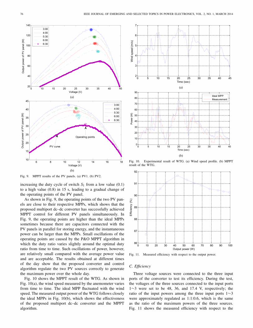
Fig. 10 shows the MPPT result of the WTG. As shown inFig. 10(a), the wind speed measured by the anemometer variesfrom time to time. The ideal MPP fluctuated with the windspeed. The measured output power of the WTG follows closelythe ideal MPPs in Fig. 10(b), which shows the effectivenessof the proposed multiport dc–dc converter and the MPPTalgorithm.
Fig. 10. Experimental result of WTG. (a) Wind speed profile. (b) MPPTresult of the WTG.
Fig. 11. Measured efficiency with respect to the output power.
C. Efficiency
Three voltage sources were connected to the three inputports of the converter to test its efficiency. During the test,the voltages of the three sources connected to the input ports1∼3 were set to be 48, 36, and 17.4 V, respectively; theratio of the input powers among the three input ports 1∼3were approximately regulated as 1:1:0.6, which is the sameas the ratio of the maximum powers of the three sources.Fig. 11 shows the measured efficiency with respect to the

ZENG et al.: ISOLATED MULTIPORT DC–DC CONVERTER 77
output power of the converter. The efficiency first increaseswith the increase of the output power. Particularly, when theoutput power is 43 W, the maximum efficiency reaches 91.7%.Then, the efficiency gradually decreases with the increase ofthe load but is always higher than 90%.
VI. CONCLUSION
An isolated multiport dc–dc converter that uses the mini-mum number of switches has been proposed for simultaneouspower management of multiple renewable energy sources. Theproposed converter has been applied for simultaneous powermanagement of a three-source wind/solar hybrid generationsystem. The experimental results have been provided to showthe effectiveness of the proposed converter. The advantage ofthe proposed multiport dc–dc converter is its simple topologywhile having the capability of MPPT control for differentrenewable energy sources simultaneously. Moreover, the pro-posed converter can be easily applied for power managementof other types of renewable energy sources.
REFERENCES
[1] J. Kassakian and T. Jahns, “Evolving and emerging applications of powerelectronics in systems,” IEEE J. Emerging Sel. Topics Power Electron.,vol. 1, no. 2, pp. 47–58, Jun. 2013.
[2] O. Lucia, I. Cvetkovic, H. Sarnago, D. Boroyevich, P. Mattavelli, andF. C. Lee, “Design of home appliances for a DC-based nanogrid system:An induction range study case,” IEEE J. Emerging Sel. Topics PowerElectron., vol. 1, no. 4, pp. 315–326, Dec. 2013.
[3] J. Carr, J. Balda, and A. Mantooth, “A high frequency link multiportconverter utility interface for renewable energy resources with inte-grated energy storage,” in Proc. IEEE Energy Convers. Congr. Exposit.,Sep. 2010, pp. 3541–3548.
[4] W. Qiao, A. Sharma, J. Hudgins, E. Jones, and L. Rilett, “Wind/solarhybrid generation-based roadway microgrids,” in Proc. IEEE PowerEnergy Soc. General Meeting, Jul. 2011, pp. 1–7.
[5] Z. Qian, O. Abdel-Rahman, and I. Batarseh, “An integrated four-port DC/DC converter for renewable energy applications,” IEEE Trans.Power Electron., vol. 25, no. 7, pp. 1877–1887, Jul. 2010.
[6] C. Shen and S. Yang, “Multi-input converter with MPPT feature forwind-PV power generation system,” Int. J. Photoenergy, Article ID129254, pp. 129254-1–129254-13, Apr. 2013.
[7] H. Tao, A. Kotsopoulos, J. Duarte, and M. Hendrix, “Family of mul-tiport bidirectional DC-DC converters,” IEE Proc. Electr. Power Appl.,vol. 153, no. 3, pp. 451–458, May 2006.
[8] M. Qiang, Z. Xu, and W. Wu, “A novel multi-port DC-DC converter forhybrid renewable energy distributed generation systems connected topower grid,” in Proc. IEEE Int. Conf. Ind. Technol., Apr. 2008, pp. 1–5.
[9] S. Yu and A. Kwasinski, “Analysis of soft-switching isolated time-sharing multiple-input converters for DC distribution systems,” IEEETrans. Power Electron., vol. 28, no. 4, pp. 1783–1794, Apr. 2013.
[10] J. Zeng, W. Qiao, and L. Qu, “An isolated multiport DC-DC converterfor simultaneous power management of multiple renewable energysources,” in Proc. IEEE Energy Convers. Congr. Exposit., Sep. 2012,pp. 3741–3748.
[11] Q. Li and P. Wolfs, “A review of the single phase photovoltaic moduleintegrated converter topologies with three different DC link configura-tions,” IEEE Trans. Power Electron., vol. 23, no. 3, pp. 1320–1333,May 2008.
[12] H. Matsuo, T. Shigemizu, F. Kurokawa, and N. Watanabe, “Characteris-tics of the multiple-input DC-DC converter,” IEEE Trans. Ind. Electron.,vol. 51, no. 3, pp. 625–631, Jun. 2004.
[13] Y. Chen, Y. Liu, and F. Wu, “Multi-input DC/DC converter based onthe multiwinding transformer for renewable energy applications,” IEEETrans. Ind. Appl., vol. 38, no. 4, pp. 1096–1104, Aug. 2002.
[14] X. Sun, G. Pei, S. Yao, and Z. Chen, “A novel multi-port DC/DCconverter with bi-directional storage unit,” in Proc. Int. Power Electron.Motion Control Conf., Jun. 2012, pp. 1771–1775.
[15] C. Zhao, S. Round, and J. Kolar, “An isolated three-port bidirectionalDC-DC converter with decoupled power flow management,” IEEE Trans.Power Electron., vol. 23, no. 5, pp. 2443–2453, Sep. 2008.
[16] Z. Zhang, Z. Ouyang, O. Thomsen, and M. Andersen, “Analysis anddesign of a bidirectional isolated DC-DC converter for fuel cells andsupercapacitors hybrid system,” IEEE Trans. Power Electron., vol. 27,no. 2, pp. 848–859, Feb. 2012.
[17] D. Liu and H. Li, “A ZVS bi-directional DC-DC converter for multipleenergy storage elements,” IEEE Trans. Power Electron., vol. 21, no. 5,pp. 1513–1517, Sep. 2006.
[18] Z. Wang and H. Li, “Integrated MPPT and bidirectional batterycharger for PV application using one multiphase interleaved three-portDC-DC converter,” in Proc. IEEE Appl. Power Electron. Conf. Exposit.,Mar. 2011, pp. 295–300.
[19] Z. Wang and H. Li, “An integrated three-port bidirectional DC-DCconverter for PV application on a DC distribution system,” IEEE Trans.Power Electron., vol. 28, no. 10, pp. 4612–4624, Oct. 2013.
[20] F. Forest, T. Meynard, E. Laboure, B. Gelis, J. Huselstein, andJ. Brandelero, “An isolated multicell intercell transformer converter forapplications with a high step-up ratio,” IEEE Trans. Power Electron.,vol. 28, no. 3, pp. 1107–1119, Mar. 2013.
[21] G. Su and F. Peng, “A low cost, triple-voltage bus DC-DC converter forautomotive applications,” in Proc. IEEE Appl. Power Electron. Conf.Exposit., vol. 2. Mar. 2005, pp. 1015–1021.
[22] Y. Chen, A. Huang, and X. Yu, “A high step-up three-port DC-DCconverter for stand-alone PV/battery power systems,” IEEE Trans. PowerElectron., vol. 28, no. 11, pp. 5049–5062, Nov. 2013.
[23] F. Blaabjerg and K. Ma, “Future on power electronics for wind turbinesystems,” IEEE J. Emerging Sel. Topics Power Electron., vol. 1, no. 3,pp. 139–152, Sep. 2013.
[24] H. Wu, R. Chen, J. Zhang, Y. Xing, H. Hu, and H. Ge, “A familyof three-port half-bridge converters for a stand-alone renewable powersystem,” IEEE Trans. Power Electron., vol. 26, no. 9, pp. 2697–2706,Sep. 2011.
[25] W. Li, J. Xiao, Y. Zhao, and X. He, “PWM plus phase angle shift (PPAS)control scheme for combined multiport DC/DC converters,” IEEE Trans.Power Electron., vol. 27, no. 3, pp. 1479–1489, Mar. 2012.
[26] J. Zeng, W. Qiao, and L. Qu, “A single-switch isolated DC-DC con-verter for photovoltaic system,” in Proc. IEEE Energy Convers. Congr.Exposit., Sep. 2012, pp. 3446–3452.
[27] Y. Zhao, C. Wei, Z. Zhang, and W. Qiao, “A review on position/speedsensorless control for permanent-magnet synchronous machine-basedwind energy conversion systems,” IEEE J. Emerging Sel. Topics PowerElectron., vol. 1, no. 4, pp. 203–216, Dec. 2013.
[28] C. Hua, J. Lin, and C. Shen, “Implementation of a DSP-controlled pho-tovoltaic system with peak power tracking,” IEEE Trans. Ind. Electron.,vol. 45, no. 1, pp. 99–107, Feb. 1998.
Jianwu Zeng (S’10) received the B.Eng. degree inelectrical engineering from the Xi’an University ofTechnology, Xi’an, China, in 2004, and the M.S.degree in control science and engineering fromZhejiang University, Hangzhou, China, in 2006.Currently, he is working toward the Ph.D. degreein electrical engineering with the University ofNebraska-Lincoln, Lincoln, NE, USA.
He joined Eaton Electrical Co., Ltd., Shenzhen,China, in 2006, where he was an ElectronicEngineer involved in research and development
of soft-switching dc-dc converters for uninterruptible power supply. Hiscurrent research interests include power electronics, renewable energy, andcomputational intelligence.

78 IEEE JOURNAL OF EMERGING AND SELECTED TOPICS IN POWER ELECTRONICS, VOL. 2, NO. 1, MARCH 2014
Wei Qiao (S’05–M’08–SM’12) received the B.Eng.and M.Eng. degrees in electrical engineering fromZhejiang University, Hangzhou, China, in 1997 and2002, respectively, the M.S. degree in high per-formance computation for engineered systems fromSingapore-MIT Alliance, Singapore, in 2003, andthe Ph.D. degree in electrical engineering from theGeorgia Institute of Technology, Atlanta, GA, USA,in 2008.
He has been with the University of Nebraska-Lincoln, Lincoln, NE, USA, since 2008, where he
is currently an Associate Professor with the Department of Electrical Engi-neering. He is the author or co-author of three book chapters and morethan 120 papers in refereed journals and international conference proceed-ings. His current research interests include renewable energy systems, smartgrids, microgrids, condition monitoring and fault diagnosis, energy storagesystems, power electronics, electric machines and drives, and computationalintelligence for electric power and energy systems.
Dr. Qiao is an Associate Editor of the IEEE TRANSACTIONS ON INDUSTRY
APPLICATIONS and the IEEE JOURNAL OF EMERGING AND SELECTED
TOPICS IN POWER ELECTRONICS, and the Chair of the Sustainable EnergySources Technical Thrust of the IEEE Power Electronics Society. He was arecipient of the 2010 National Science Foundation CAREER Award, the 2010IEEE Industry Applications Society Andrew W. Smith Outstanding YoungMember Award, the 2012 UNL College of Engineering Faculty Researchand Creative Activity Award, the 2011 UNL Harold and Esther EdgertonJunior Faculty Award, and the 2011 UNL College of Engineering EdgertonInnovation Award. He has received four Best Paper Awards from IEEE IAS,PES, and PELS.
Liyan Qu (S’05–M’08) received the B.Eng. (Hons.)and M.Eng. degrees in electrical engineering fromZhejiang University, Hangzhou, China, in 1999 and2002, respectively, and the Ph.D. degree in electri-cal engineering from the University of Illinois atUrbana-Champaign, Urbana, IL, USA, in 2007.
She was an Application Engineer with AnsoftCorporation, Pittsburgh, PA, USA, from 2007 to2009. She has been with the University of Nebraska-Lincoln, Lincoln, NE, USA, since 2010, where she iscurrently an Assistant Professor with the Department
of Electrical Engineering. Her current research interests include energyefficiency, renewable energy, numerical analysis and computer aided designof electric machinery and power electronic devices, dynamics and control ofelectric machinery, permanent-magnet machines, and magnetic materials.
Yanping Jiao (S’10) received the B.Eng. degreein electrical engineering from Tianjin University,Tianjin, China, in 2006, and the Ph.D. degree inelectrical engineering from Nanyang TechnologicalUniversity, Singapore, in 2012.
She was a Post-Doctoral Researcher with theDepartment of Electrical Engineering, University ofNebraska-Lincoln, Lincoln, NE, USA, from 2011 to2013. Her current research interests include powerconverters, renewable energy, energy managementsystem, and smart grid.