an li - biological wastewater treatment - selecting the process
TRANSCRIPT
Chemical, pharmaceutical and related industries produce large amounts of wastewater in their production and cleaning pro-
cesses. The wastewater characteris-tics are often diverse, and may include minimally biodegradable or toxic sub-stances, or both. To protect the envi-ronment, these wastewaters typically must be treated to minimize pollut-ant concentrations before discharging to the environment, or to municipal wastewater-treatment plants for fur-ther treatment. Compared to chemical and physical treatment methods, bio-logical treatment processes are very economical and efficient options when the wastewaters contain biodegrad-able pollutants.
Biological wastewater-treatment processes are widely adapted to re-move soluble, colloidal and suspended organic substances. Biological treat-ment is also used for nitrogen and phosphorus removal. The two catego-ries of biological treatment are sus-pended-growth and attached-growth processes. In the suspended-growth category, the most widely used pro-cess is activated sludge. An attached-growth process that can provide the same treatment capacity as activated sludge in a smaller footprint (60% less) is the moving bed biofilm reactor (MBBR). The first MBBR was installed in Steinsholt, Norway in 1989. Today,
as regulatory restrictions continue to become more stringent, MBBR tech-nology is becoming increasingly popu-lar due to its application flexibility.
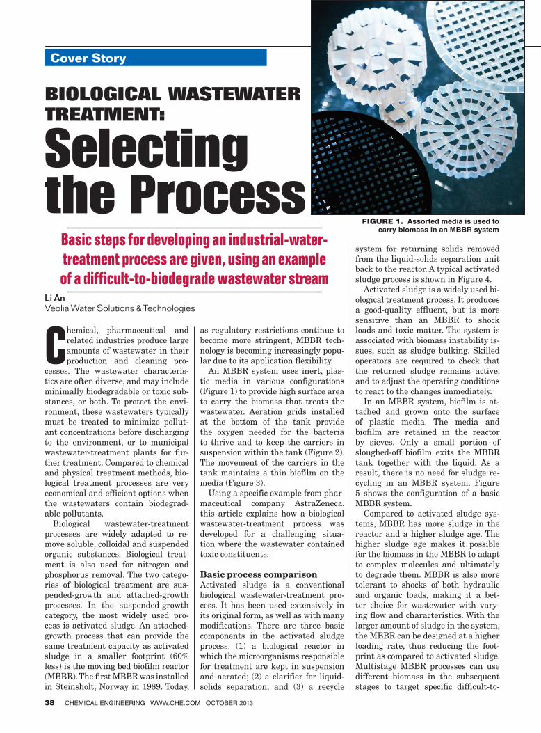
An MBBR system uses inert, plas-tic media in various configurations (Figure 1) to provide high surface area to carry the biomass that treats the wastewater. Aeration grids installed at the bottom of the tank provide the oxygen needed for the bacteria to thrive and to keep the carriers in suspension within the tank (Figure 2). The movement of the carriers in the tank maintains a thin biofilm on the media (Figure 3).
Using a specific example from phar-maceutical company AstraZeneca, this article explains how a biological wastewater-treatment process was developed for a challenging situa-tion where the wastewater contained toxic constituents.
Basic process comparisonActivated sludge is a conventional biological wastewater-treatment pro-cess. It has been used extensively in its original form, as well as with many modifications. There are three basic components in the activated sludge process: (1) a biological reactor in which the microorganisms responsible for treatment are kept in suspension and aerated; (2) a clarifier for liquid-solids separation; and (3) a recycle
system for returning solids removed from the liquid-solids separation unit back to the reactor. A typical activated sludge process is shown in Figure 4.
Activated sludge is a widely used bi-ological treatment process. It produces a good-quality effluent, but is more sensitive than an MBBR to shock loads and toxic matter. The system is associated with biomass instability is-sues, such as sludge bulking. Skilled operators are required to check that the returned sludge remains active, and to adjust the operating conditions to react to the changes immediately.
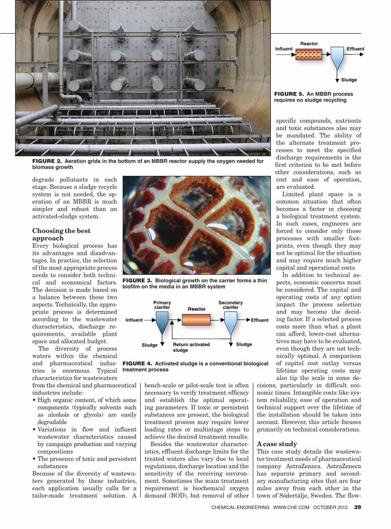
In an MBBR system, biofilm is at-tached and grown onto the surface of plastic media. The media and biofilm are retained in the reactor by sieves. Only a small portion of sloughed-off biofilm exits the MBBR tank together with the liquid. As a result, there is no need for sludge re-cycling in an MBBR system. Figure 5 shows the configuration of a basic MBBR system.
Compared to activated sludge sys-tems, MBBR has more sludge in the reactor and a higher sludge age. The higher sludge age makes it possible for the biomass in the MBBR to adapt to complex molecules and ultimately to degrade them. MBBR is also more tolerant to shocks of both hydraulic and organic loads, making it a bet-ter choice for wastewater with vary-ing flow and characteristics. With the larger amount of sludge in the system, the MBBR can be designed at a higher loading rate, thus reducing the foot-print as compared to activated sludge. Multistage MBBR processes can use different biomass in the subsequent stages to target specific difficult-to-
Feature Report
38 ChemiCal engineering www.Che.Com oCtober 2013
Cover Story
Li AnVeolia Water Solutions & Technologies
Basic steps for developing an industrial-water-treatment process are given, using an example of a difficult-to-biodegrade wastewater stream
Biological WasteWater treatment:
Selecting the Process
Figure 1. Assorted media is used to carry biomass in an MBBR system
16_CHE_100113_MPB.indd 38 9/19/13 6:56:48 AM
degrade pollutants in each stage. Because a sludge recycle system is not needed, the op-eration of an MBBR is much simpler and robust than an activated-sludge system.
Choosing the best approachEvery biological process has its advantages and disadvan-tages. In practice, the selection of the most appropriate process needs to consider both techni-cal and economical factors. The decision is made based on a balance between these two aspects. Technically, the appro-priate process is determined according to the wastewater characteristics, discharge re-quirements, available plant space and allocated budget.
The diversity of process waters within the chemical and pharmaceutical indus-tries is enormous. Typical characteristics for wastewaters from the chemical and pharmaceuticalindustries include:• High organic content, of which some
components (typically solvents such as alcohols or glycols) are easily degradable
• Variations in flow and influent wastewater characteristics caused by campaign production and varying compositions
• The presence of toxic and persistent substances
Because of the diversity of wastewa-ters generated by these industries, each application usually calls for a tailor-made treatment solution. A
bench-scale or pilot-scale test is often necessary to verify treatment efficacy and establish the optimal operat-ing parameters. If toxic or persistent substances are present, the biological treatment process may require lower loading rates or multistage steps to achieve the desired treatment results.
Besides the wastewater character-istics, effluent discharge limits for the treated waters also vary due to local regulations, discharge location and the sensitivity of the receiving environ-ment. Sometimes the main treatment requirement is biochemical oxygen demand (BOD), but removal of other
specific compounds, nutrients and toxic substances also may be mandated. The ability of the alternate treatment pro-cesses to meet the specified discharge requirements is the first criterion to be met before other considerations, such as cost and ease of operation,are evaluated.
Limited plant space is a common situation that often becomes a factor in choosing a biological treatment system. In such cases, engineers are forced to consider only those processes with smaller foot-prints, even though they may not be optimal for the situation and may require much higher capital and operational costs.
In addition to technical as-pects, economic concerns must be considered. The capital and operating costs of any option impact the process selection and may become the decid-ing factor. If a selected process costs more than what a plant can afford, lower-cost alterna-tives may have to be evaluated, even though they are not tech-nically optimal. A comparison of capital cost outlay versus lifetime operating costs may also tip the scale in some de-
cisions, particularly in difficult eco-nomic times. Intangible costs like sys-tem reliability, ease of operation and technical support over the lifetime of the installation should be taken into account. However, this article focuses primarily on technical considerations.
A case studyThis case study details the wastewa-ter treatment needs of pharmaceutical company AstraZeneca. AstraZeneca has separate primary and second-ary manufacturing sites that are four miles away from each other in the town of Södertälje, Sweden. The flow-
CHEMICAL ENGINEERING WWW.CHE.COM OCTOBER 2013 39
Primaryclarifer
Secondaryclarifer
Return activatedsludge
Reactor
SludgeSludge
Influent Effluent
Reactor
Reactor
Sludge
Influent Effluent
FIGURE 2. Aeration grids in the bottom of an MBBR reactor supply the oxygen needed for biomass growth
FIGURE 3. Biological growth on the carrier forms a thin bio� lm on the media in an MBBR system
FIGURE 4. Activated sludge is a conventional biological treatment process
FIGURE 5. An MBBR process requires no sludge recycling
16_CHE_100113_MPB.indd 39 9/19/13 7:04:11 AM

Cover Story
40 CHEMICAL ENGINEERING WWW.CHE.COM OCTOBER 2013
rate of wastewater from the primary plant was 260,000 gallons per day (gal/d) with chemical oxygen demand (COD) of 3,000–4,000 milligrams/liter (mg/L). The flowrate of wastewater from the secondary plant was 26,000 gal/d with COD of 80–1,600 mg/L. These two sites are connected by a sewage line. The primary plant used activated sludge to treat its wastewa-ter; the secondary plant used activated carbon for the removal of toxicity.
A Swedish Environmental Pro-tection Agency (EPA) investigation showed that these wastewaters were very toxic and contained hard-to-degrade organics and phosphorus, and stricter limits were about to be issued. To ensure compliance with the anticipated regulations, Astra-Zeneca decided to build a new waste-water treatment plant to meet the requirements for discharge of the treated wastewater to Lake Mälaren. This lake neighbors several cities, including Stockholm.
AstraZeneca sought alternative methods to obtain a solution for the new treatment plant. To be able to discharge the wastewater into Lake Mälaren, the treatment plant efflu-ent had to be free of toxic chemicals and, at the same time, at least 95% of the organic content had to be re-moved. The wastewater was evaluated and an optimal biological treatment
approach was developed to meet the discharge requirements. Below is the step-by-step process used to evaluate the alternatives and develop the best treatment option. Step 1: Obtain wastewater char-acteristics and site information. Flowrates, wastewater characteris-tics, discharge limits and local envi-ronmental conditions were among the data obtained from the sites. The space at the primary plant was lim-ited, but there was space for the new wastewater-treatment facility at the secondary plant.Step 2: Evaluate and summarize the information. According to the in-formation collected, the toxicity of the wastewater in question was a major problem. Toxic substances typically inhibit biological treatment. In some cases, the bacteria can become accli-mated to the toxic wastewater, and sometimes toxic wastewater can be pre-treated to become biodegradable. If no economical pre-treatment can make the toxic wastewater biodegrad-able, a non-biological treatment must be considered.Step 3: Examine the wastewater’s biodegradablility. If the wastewa-ter has common characteristics and information can be drawn from proj-ect experience, laboratory testing is not necessary. However, laboratory testing is recommended for complex
industrial wastewaters such as these. An initial evaluation was conducted in the laboratory to determine whether the wastewater was biodegradable and whether the toxicity of the waste-water would be reduced after the bio-logical treatment. Various wastewater streams (labelled A through I) were collected from both the primary and secondary plants. A continuous labo-ratory-scale activated-sludge process was used for this work. The tempera-ture for the study was 20°C and the pH was 7. Influent and effluent COD and toxicity were measured. The con-tribution of toxicity from each stream was calculated as toxicity units, as measured by a Microtox test system, which uses luminescent bacteria to determine the toxicity of a sample. When exposed to a toxic sample, the amount of light emitted by the bac-teria is decreased. The more toxic a sample, the less light will be produced by the bacteria. Here, toxicity is cal-culated as flowrate in m3/day × 100/EC 50, 15 min, where EC50, 15 min represents the effective concentration (EC) of a sample that will cause a 50% reduction in light emission after 15 minutes of exposure of a sample to the test bacteria[1]. The laboratory study results are shown in Figure 6 (for the primary plant) and Figure 7 (for the secondary plant).
Based on the results shown in Figure
Before treatmentAfter treatment
Before treatmentAfter treatment
0
200
600
800
1,000
1,600
1,800
2,000
2,200
2,400
2,600
0
10,000
15,000
25,000
30,000COD TOXICITY
B. 1
4,50
0 ga
l/d
C.1
13,6
00 g
al/d
E.1
7,17
0 ga
l/d
CO
D, l
b/d
Toxi
city
uni
ts, M
icro
tox
A.8
9,80
0 ga
l/d
D. 2
,640
gal
/d
F.26
,400
gal
/d
1,400
1,200
400
20,000
5,000
B. 1
4,50
0 ga
l/d
C.1
13,6
00 g
al/d
E.1
7,17
0 ga
l/d
A.8
9,80
0 ga
l/d
D. 2
,640
gal
/d
F.26
,400
gal
/d
0
20
40
60
80
100
120
140
160
180
200
CO
D lb
/d
0
500
1,000
1,500
2,000COD TOXICITY
G. 1
30 g
al/d
H. 1
20 g
al/d
I. 39
5 ga
l/d
Toxi
city
uni
ts, M
icro
tox
G. 1
30 g
al/d
H. 1
20 g
al/d
I. 39
5 ga
l/d
Before treatmentAfter treatment
Before treatmentAfter treatment
FIGURE 6. These charts show COD and toxicity before and after biological treatment of primary plant wastewater [1]
FIGURE 7. These charts show COD and toxicity before and after biological treatment of secondary plant wastewater [1]
16_CHE_100113_MPB.indd 40 9/19/13 7:06:30 AM

CHEMICAL ENGINEERING WWW.CHE.COM OCTOBER 2013 41
6, the COD and toxicity are significantly removed by the biological treatment pro-cess. From the left chart of Figure 6, we can see Stream B of the primary plant contains some hard-to-treat compounds. From the right chart of Figure 6, we can see that Stream B has high toxicity be-fore biological treatment, but the toxic-ity is lower after biological treatment. When the biological effluent was further treated by activated carbon, the toxicity was completely removed. The specific components of Stream B that indicated higher toxicity were separated at the source. Activated carbon was also used to polish the effluent by removing the maximum toxicity.
Figure 7 shows the results of COD and toxicity treatment for the secondary plant wastewater. Stream G had both high COD and toxicity, but both COD and toxicity were significantly removed by biological treatment. Stream I had lower COD but relatively high toxicity. To minimize the toxicity of the wastewater, activated carbon was used to pre-treat Stream I.
It could be concluded, based on the results of the initial evaluation, that the wastewater from both plants could be treated with a biological treatment sys-tem by employing appropriate pretreat-ment.Step 4: Assess potential biologi-cal treatment options. When it is known that the wastewater is biode-
gradable, the next step is to choose the best biological-treatment approach for the specific wastewater. For industrial wastewater with typical character-istics, it is possible to determine the appropriate biological-treatment ap-proach without testing, simply based on expertise. However, biological treatment mechanisms are complex. If the industrial waste stream has challenging characteristics, the best way to select the appropriate biologi-cal wastewater-treatment approach is to test the wastewater by laboratory or pilot study.
The wastewater from the primary plant was tested using nine different combinations of continuous activated sludge, and MBBR processes, or both, in the laboratory. These combinations included fungi and bacteria in differ-ent reactors in a series. The processes were evaluated based on the removal efficiencies of both COD and toxic-ity. Sludge volume index (SVI) was adapted to evaluate the settling char-acteristics of the generated sludge. A microscope was also used to examine the generated sludge. Appropriate media was placed in the MBBR reac-tors as the carrier for the microorgan-ism growth. The system temperature was maintained at 30°C and pH was maintained at 7. Details of the results from each of the nine test options are below.
A conventional single-stage acti-vated sludge process (Figure 8) was tested as Option 1. It included one activated sludge reactor and one secondary clarifier. This process re-moved over 90% of the COD at a hy-draulic retention time (HRT) larger than 16 hours. The SVI of the sludge was greater than 200, which was not acceptable; therefore, Option 1’s sin-gle-stage conventional sludge process was eliminated as a potential treat-ment option for this wastewater.
Option 2 tested a two-stage acti-vated sludge process (Figure 9) with different types of sludge in each tank. This process allowed for different bac-teria in each reactor so that the bacte-ria could work on specific wastewater constituents. The results showed that the sludge in the first reactor did not settle well, and the sludge in the sec-ond reactor was not viable when the first stage had high removal rates. Hence, Option 2 was not considered as an approach for the treatment ofthis wastewater.
Option 3 is a modification of the two-stage process (Figure 10) with two different sludges. Sludge settling and wash-out problems were evident with this approach, so Option 3 was eliminated from consideration.
Option 4 tested a modified activated sludge process (Figure 11) that used a selector with one-hour HRT in front of
FIGURE 8. Option 1 tested a conventional activated-sludge process including one reactor and one sec-ondary clari� er
FIGURE 9. Option 2 tested a two-stage activated-sludge process with different sludges
FIGURE 10. Option 3 tested a two-stage activated-sludge process with the same sludge in both tanks
FIGURE 11. Option 4 tested a modi� ed activated-sludge process with an aerobic selector
16_CHE_100113_MPB.indd 41 9/19/13 7:08:00 AM

Cover Story
42 CHEMICAL ENGINEERING WWW.CHE.COM OCTOBER 2013
front of the conventional activated-sludge process. The selector was run under aerobic conditions. Good re-moval of soluble COD and total COD were obtained. The SVI was below 80, which indicates the good settling characteristics of the sludge gener-ated by this process. The HRT of the main activated-sludge reactor was 14 hours. This process removed 90–95% COD, but the removal of toxicity was not sufficient. A higher HRT of the main reactor was tested, but this did not remove any additional COD and the sludge deteriorated due to the formation of pinpoint floc. Option 4 showed potential to be considered as a viable solution.
A single-stage, standalone MBBR reactor filled with media (Figure 12)
was tested in Option 5. A very high concentration of free bacteria was ob-served, which was most likely due to the presence of 10–20% readily biode-gradable organics in the wastewater. Free bacteria could not be maintained below the HRT of 30 minutes, and the influent was washed out without treatment. Option 5 was not appropri-ate for the wastewater because of the difficulty in separating the free bacte-ria from the effluent.
The presence of micro-fungi in the activated sludge treatment plant at the primary plant inspired Option 6, as fungi can affect treatment results. For Option 6, the MBBR reactor was run at a pH of 4 to favor the growth of fungi in the MBBR process (Figure 13). Fungal hyphae quickly formed on the media and yeast cells were observed when the HRT was greater than three hours. However, poor COD removal resulted from the single-stage fungal MBBR process, eliminating Option 6 from further consideration.
Option 7 tested a three-stage fungal MBBR process (Figure 14), where the HRT of each stage was three hours. The pH was controlled at 4. This process removed only 60–70% COD,
which was not adequate. Option 7was abandoned.
Option 8’s treatment approach con-sisted of Option 4 (modified activated sludge) followed by two MBBR reac-tors (Figure 15). The HRT of this pro-cess was 14 hours. The results showed no further COD or toxicity removal compared to the effluent of Option 4, so Option 8 was abandoned.
And lastly, Option 9 was tested in order to remove the remaining COD from the effluent of the three-stage fungal MBBR process in Option 7. Op-tion 9 consists of three fungal MBBR reactors followed by a two-stage bac-terial MBBR process (Figure 16). The HRT was three hours for each fungal MBBR reactor. The operational pH was maintained at 4 to benefit the growth of fungi. Two bacterial MBBR reactors were placed after the fungal MBBR stages to remove more biodegrad-able COD. The pH was maintained at 7 in the bacterial MBBR reactors. This process removed around 90–95% COD, and the removal of toxicity was far more effective than the modified activated sludge process in Option 4. It was easier to separate solid and liq-uid phases, and the effluent was very
FIGURE 13. Option 6 tested a single-stage fungal MBBR process
FIGURE 14. Option 7 tested a three-stage fungal MBBR process
FIGURE 15. Option 8 tested a modi� ed activated sludge process followed by a two-stage bacterial MBBR process
FIGURE 16. Three fungal MBBR reactors followed by a two-stage bacterial MBBR process
FIGURE 12. Option 5 tested a single-stage bacterial MBBR process
16_CHE_100113_MPB.indd 42 9/19/13 7:31:34 AM
CHEMICAL ENGINEERING WWW.CHE.COM OCTOBER 2013 43
clear. This process was deemed an ap-propriate potential approach for the wastewater.
Further studies showed that when the sludge from the fungal MBBR reactors was removed before the bacterial MBBR treatment, the sys-tem exhibited more effective COD and toxicity elimination. Therefore, a clarifier was added in front of the two-stage bacteria MBBR reactors to remove the excess sludge from the previous fungal MBBR reactors.Step 5: Determine the most appropriate treatment processBased on the laboratory test results, both Option 4 and Option 9 showed similar COD removal results (90–95%). Option 9 resulted in far better toxic-ity removal, which could be the result of the longer HRT in the MBBR pro-cess. Option 8 showed that adding two MBBR reactors did not improve COD or toxicity removal for the effluent of Op-tion 4. It was thought that the fungal MBBR reactors of Option 9 improved the toxicity removal. According to these results, Option 9 was chosen as the most appropriate biological wastewa-ter-treatment process for this specific wastewater. Pilot tests conducted later confirmed the laboratory test results. In the full-scale installation, activated carbon was also introduced after the biological treatment steps to remove any remaining toxicity in the effluentfrom Option 9.
A complex, yet simple solutionThis case study illustrates the capa-bility of an MBBR system to utilize microbial populations that can tar-get specific constituents in complex wastewater. This capability is a dis-tinct advantage over other biological
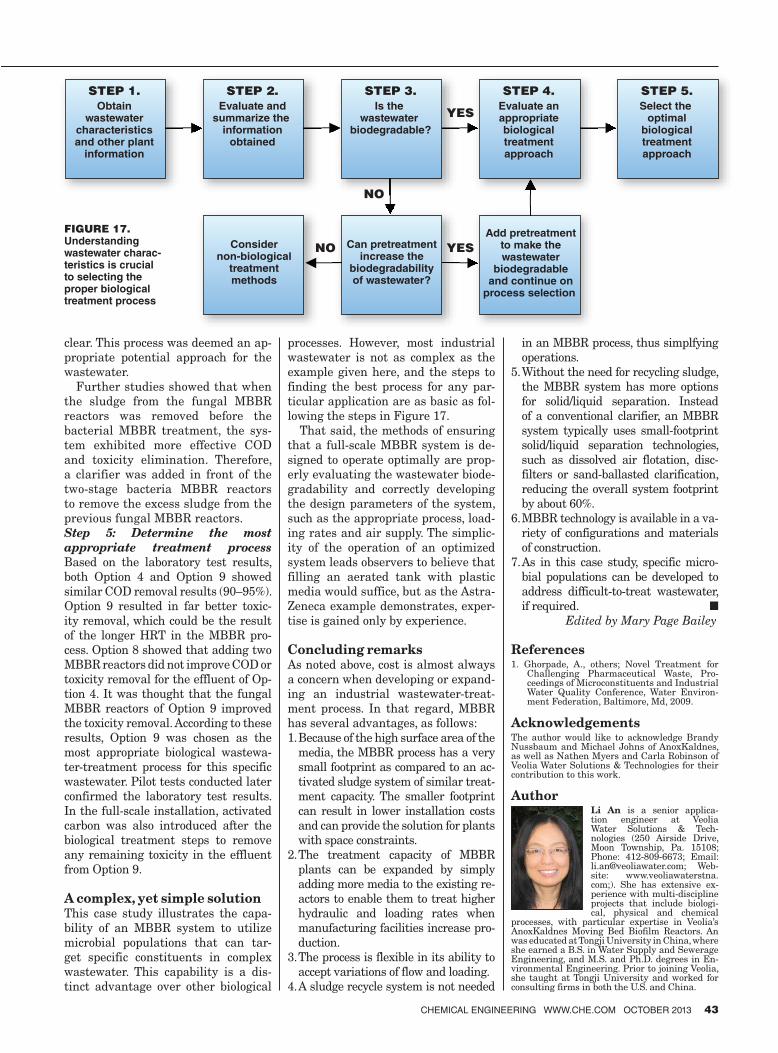
processes. However, most industrial wastewater is not as complex as the example given here, and the steps to finding the best process for any par-ticular application are as basic as fol-lowing the steps in Figure 17.
That said, the methods of ensuring that a full-scale MBBR system is de-signed to operate optimally are prop-erly evaluating the wastewater biode-gradability and correctly developing the design parameters of the system, such as the appropriate process, load-ing rates and air supply. The simplic-ity of the operation of an optimized system leads observers to believe that filling an aerated tank with plastic media would suffice, but as the Astra-Zeneca example demonstrates, exper-tise is gained only by experience.
Concluding remarksAs noted above, cost is almost always a concern when developing or expand-ing an industrial wastewater-treat-ment process. In that regard, MBBR has several advantages, as follows:1. Because of the high surface area of the
media, the MBBR process has a very small footprint as compared to an ac-tivated sludge system of similar treat-ment capacity. The smaller footprint can result in lower installation costs and can provide the solution for plants with space constraints.
2. The treatment capacity of MBBR plants can be expanded by simply adding more media to the existing re-actors to enable them to treat higher hydraulic and loading rates when manufacturing facilities increase pro-duction.
3. The process is flexible in its ability to accept variations of flow and loading.
4. A sludge recycle system is not needed
in an MBBR process, thus simplfying operations.
5. Without the need for recycling sludge, the MBBR system has more options for solid/liquid separation. Instead of a conventional clarifier, an MBBR system typically uses small-footprint solid/liquid separation technologies, such as dissolved air flotation, disc-filters or sand-ballasted clarification, reducing the overall system footprint by about 60%.
6. MBBR technology is available in a va-riety of configurations and materials of construction.
7. As in this case study, specific micro-bial populations can be developed to address difficult-to-treat wastewater, if required. ■ Edited by Mary Page Bailey
References1. Ghorpade, A., others; Novel Treatment for
Challenging Pharmaceutical Waste, Pro-ceedings of Microconstituents and Industrial Water Quality Conference, Water Environ-ment Federation, Baltimore, Md, 2009.
AcknowledgementsThe author would like to acknowledge Brandy Nussbaum and Michael Johns of AnoxKaldnes, as well as Nathen Myers and Carla Robinson of Veolia Water Solutions & Technologies for their contribution to this work.
AuthorLi An is a senior applica-tion engineer at Veolia Water Solutions & Tech-nologies (250 Airside Drive, Moon Township, Pa. 15108; Phone: 412-809-6673; Email: [email protected]; Web-site: www.veoliawaterstna.com;). She has extensive ex-perience with multi-discipline projects that include biologi-cal, physical and chemical
processes, with particular expertise in Veolia’s AnoxKaldnes Moving Bed Biofilm Reactors. An was educated at Tongji University in China, where she earned a B.S. in Water Supply and Sewerage Engineering, and M.S. and Ph.D. degrees in En-vironmental Engineering. Prior to joining Veolia, she taught at Tongji University and worked for consulting firms in both the U.S. and China.
STEP 1.Obtain
wastewatercharacteristicsand other plant
information
STEP 2.Evaluate and
summarize the information
obtained
STEP 3.Is the
wastewater biodegradable?
Considernon-biological
treatmentmethods
STEP 4.Evaluate anappropriatebiologicaltreatmentapproach
STEP 5.Select the
optimalbiologicaltreatmentapproach
NO
YES
YESNO Can pretreatmentincrease the
biodegradabilityof wastewater?
Add pretreatmentto make thewastewater
biodegradableand continue on
process selection
FIGURE 17. Understanding wastewater charac-teristics is crucial to selecting the proper biological treatment process
16_CHE_100113_MPB.indd 43 9/19/13 7:33:27 AM