an lpwan-agnostic application layer for the iot in …
TRANSCRIPT

Artturi Rämänen
AN LPWAN-AGNOSTIC APPLICATION LAYERFOR THE IOT IN FINLAND
Supervisors: Professor Pertti SilventoinenAdjunct Professor Tapio Saarelainen
Advisors: Turkka Laakkio M.Sc. (Tech)Jyrki Ojaniemi M.Sc. (Tech)
ABSTRACT
Lappeenranta-Lahti University of Technology LUTLUT School of Energy SystemsElectrical Engineering
Artturi RämänenAn LPWAN-Agnostic Application Layer for the IoT in Finland
2019
Master’s thesis.60 p.
Examiners: Professor Pertti SilventoinenAdjunct Professor Tapio Saarelainen
Multiple Low Power Wireless Area Networks (LPWANs) currently operate in Fin-land. A typical part of an IoT application is a battery operated node which collectsdata from sensors and forwards it over LPWAN to a cloud system.
Studies on technical differences among pairs of LPWANs exist but few studies ex-ist on application-level possibilities of the networks. This thesis studies how datafrom sensor-nodes using Sigfox, LoRaWAN and NB-IoT could be routed to an IoTapplication with no LPWAN interfaces, while preserving multi-year battery life.
A literature review of the features affecting the application level use of the LPWANswas conducted. Based on the results of the review, an application was created tointerface between the IoT server application and nodes in the three LPWANs.
LPWAN-agnostic communication to and from end-nodes using the studied LPWANswas found to be a viable approach for IoT applications. Frequency and size ofuplink transmissions were unaffected, but downlink transmissions were limited to amaximum of 8 bytes four times a day.
iii
TIIVISTELMÄ
Lappeenrannan–Lahden teknillinen yliopisto LUTLUT School of Energy SystemsSähkötekniikka
Artturi RämänenLPWAN-riippumaton sovellustason tiedonsiirto Suomen IoT:ssa
2019
Diplomityö.60 s.
Tarkastajat: Professori Pertti SilventoinenDosentti Tapio Saarelainen
Suomessa on käytössä useita matalan virrankulutuksen langattomia laaja-alaisiaverkkoyhteyksiä (engl. Low Power Wide Area Network, LPWAN). TyypillinenIoT-sovelluksen komponentti on akkukäyttöinen sensorisolmu, joka lähettää ker-äämäänsä tiedon LPWAN:in avulla pilvisovellukseen.
LPWAN-parien välisiä teknisiä eroavaisuuksia käsitteleviä tutkimuksia on lukuisia,mutta verkkojen käytännön sovellustason mahdollisuuksia käsitteleviä tutkimuksiaei ole paljon. Tämä diplomityö tutkii sitä kuinka Sigfox, LoRaWAN ja NB-IoTverkoissa toimivien sensorisolmujen data voidaan reitittää IoT-sovellukseen, joka eisisällä LPWAN-spesifisiä rajapintoja, niin että sensorisolmujen usean vuoden ak-unkesto säilyy.
Aihetta tutkittiin ensin tutustumalla LPWAN:ien sovellustason käyttöön vaikut-taviin ominaisuuksiin. Näiden perusteella toteutettiin sovellus tulkkaamaan IoT-palvelinsovelluksen ja kolmen LPWAN:in sensorisolmujen välistä kommunikointia.
LPWAN:ista riippumattoman tiedonsiirtoyhteyden todettiin sopivan IoT-sovelluk-sien kehittämisen perustaksi. Lähestymistapa ei lisää rajoituksia sensorisolmustalähetettävän datan määrään tai tiedonsiirron tiheyteen, mutta sensorisolmulle lähet-ettävien pakettien koko ja lähetystiheys on rajoitettava maksimissaan 8 tavuun 4kertaa vuorokauden aikana.

iv
Preface
This thesis was brought about by my move to Turku in early 2018. During thecourse of 2018 I have had the chance to research the subject of this thesis deeply,and to develop my understanding of not only low power communication, but also ofbest practices in software development and of the troubles in developing applicationswith cutting-edge technology.
Firstly I would like to thank my supervisors, Professor Pertti Silventoinen and Ad-junct Professor Tapio Saarelainen, for the guidance that they have provided dur-ing the course of this thesis. The work for this thesis couldn’t have progressed asstraightforwardly as it did without it. Secondly, I would like to thank the whole ofRCP Software and especially my instructors Turkka Laakkio and Jyrki Ojaniemi forthe direction and support given to me while I was constructing this thesis. Thankyou for giving me the chance to apply such continued focus on this topic.
Thirdly, thank you to my family and friends for your support both before and whileI was writing this thesis. Inka, thank you for your help and continued support forme and my projects. You’ve all been a blessing to me.
Turku, 4.1.2019
Artturi L. I. Rämänen
v
Contents
Preface iv
Contents v
Abbreviations vii
1 Introduction 11.1 Objectives . . . . . . . . . . . . . . . . . . . . . . . . . . . . . . . . . 11.2 Scope of thesis . . . . . . . . . . . . . . . . . . . . . . . . . . . . . . 21.3 Structure of thesis . . . . . . . . . . . . . . . . . . . . . . . . . . . . 3
2 Background 42.1 M2M communication . . . . . . . . . . . . . . . . . . . . . . . . . . . 42.2 Types of IoT Data . . . . . . . . . . . . . . . . . . . . . . . . . . . . 52.3 IoT Device Constraints . . . . . . . . . . . . . . . . . . . . . . . . . . 52.4 Sigfox . . . . . . . . . . . . . . . . . . . . . . . . . . . . . . . . . . . 6
2.4.1 Architecture . . . . . . . . . . . . . . . . . . . . . . . . . . . . 62.4.2 Transmission Specifics . . . . . . . . . . . . . . . . . . . . . . 62.4.3 Security . . . . . . . . . . . . . . . . . . . . . . . . . . . . . . 72.4.4 Managing Power Consumption . . . . . . . . . . . . . . . . . . 82.4.5 Configuration . . . . . . . . . . . . . . . . . . . . . . . . . . . 9
2.5 LoRaWAN . . . . . . . . . . . . . . . . . . . . . . . . . . . . . . . . . 102.5.1 Architecture . . . . . . . . . . . . . . . . . . . . . . . . . . . . 102.5.2 Transmission and End-node Specifics . . . . . . . . . . . . . . 112.5.3 Security . . . . . . . . . . . . . . . . . . . . . . . . . . . . . . 132.5.4 Managing Power Consumption . . . . . . . . . . . . . . . . . . 14
2.6 NB-IoT . . . . . . . . . . . . . . . . . . . . . . . . . . . . . . . . . . 152.6.1 Architecture . . . . . . . . . . . . . . . . . . . . . . . . . . . . 162.6.2 Connectivity Options . . . . . . . . . . . . . . . . . . . . . . . 182.6.3 Security (Non-IP) . . . . . . . . . . . . . . . . . . . . . . . . . 192.6.4 Security (IP) . . . . . . . . . . . . . . . . . . . . . . . . . . . 192.6.5 Managing Power Consumption . . . . . . . . . . . . . . . . . . 22
2.7 Data Serialization . . . . . . . . . . . . . . . . . . . . . . . . . . . . . 232.8 CoAP . . . . . . . . . . . . . . . . . . . . . . . . . . . . . . . . . . . 26
2.8.1 OSCORE . . . . . . . . . . . . . . . . . . . . . . . . . . . . . 292.9 Docker . . . . . . . . . . . . . . . . . . . . . . . . . . . . . . . . . . . 30

vi
3 Environment and Requirements 313.1 End-nodes . . . . . . . . . . . . . . . . . . . . . . . . . . . . . . . . . 323.2 LPWAN-Specific Hardware and Software . . . . . . . . . . . . . . . . 323.3 Server Runtime Environment and IoT Application . . . . . . . . . . . 34
4 Implementation 354.1 Sigfox . . . . . . . . . . . . . . . . . . . . . . . . . . . . . . . . . . . 354.2 LoRaWAN . . . . . . . . . . . . . . . . . . . . . . . . . . . . . . . . . 364.3 NB-IoT . . . . . . . . . . . . . . . . . . . . . . . . . . . . . . . . . . 37
4.3.1 Security . . . . . . . . . . . . . . . . . . . . . . . . . . . . . . 374.3.2 Software Used . . . . . . . . . . . . . . . . . . . . . . . . . . . 384.3.3 Architecture . . . . . . . . . . . . . . . . . . . . . . . . . . . . 39
4.4 Outcome and Future Work . . . . . . . . . . . . . . . . . . . . . . . . 40
5 Discussion 425.1 General . . . . . . . . . . . . . . . . . . . . . . . . . . . . . . . . . . 425.2 Sigfox . . . . . . . . . . . . . . . . . . . . . . . . . . . . . . . . . . . 435.3 LoRaWAN . . . . . . . . . . . . . . . . . . . . . . . . . . . . . . . . . 455.4 NB-IoT . . . . . . . . . . . . . . . . . . . . . . . . . . . . . . . . . . 465.5 Implementation . . . . . . . . . . . . . . . . . . . . . . . . . . . . . . 48
6 Conclusions 506.1 Technical similarities . . . . . . . . . . . . . . . . . . . . . . . . . . . 506.2 Security . . . . . . . . . . . . . . . . . . . . . . . . . . . . . . . . . . 516.3 Limitations . . . . . . . . . . . . . . . . . . . . . . . . . . . . . . . . 52
A Sigfox Callback Response Format 60
vii
Abbreviations
LPWAN Low-power wide-area networkIoT Internet of ThingsLwM2M Lightweight Machine to Machine ProtocolWiFi IEEE 802.11xM2M Machine to machine4G Fourth generation cellular broadband5G Fifth generation cellular broadbandISM Industrial, scientific and medical bandsIP Internet ProtocolNB-IoT Narrowband IoT (LPWAN)REST Representational state transferAPI Application programming interfaceETSI European Telecommunications Standards InstituteHTTP HyperText Transfer ProtocolFOTA Firmware over-the-airSNR Signal to noise ratioCSS Chirp spread spectrumMAC Medium access controlTCP Transmission Control ProtocolDevEUI Device EUIAppEUI Application EUIOTAA Over the air activationABP Activation by personalizationGPS Global Positioning SystemTOA Time on airPHY Physical layerCRC Cyclic redundancy checkDR Data rateADR Automatic data rateMQTT Message queuing telemetry transport3GPP Third Generation Partnership ProjectMNO Mobile network operatorLTE Long term evolutionGSM Global System for Mobile communicationsUE User equipmentS-GW Serving gatewayP-GW Packet gatewayMME Mobility management entityQoS Quality of ServiceSCEF Service capability exposure functionID IdentifierRAN Radio access network

viii
CIoT Cellular IoTMTC Mobile-type communicationsSIM Subscriber identity moduleTLS Transport Layer SecurityUDP User Datagram ProtocolDTLS Datagram TLS3G Third generation cellular broadbandRFC Request for commentsPSK Pre-shared keyPSM Power saving modeTAU Tracking area updateJSON JavaScript Object NotationXML eXtensible Markup LanguageCBOR Concise Binary Object RepresentationSenML Sensor Measurement ListsCoAP Constrained Application ProtocolURI Uniform Resource IdentifierSCTP Stream Control Transmission ProtocolOSCORE Object Security for Constrained RESTful EnvironmentsCPU Central Processing UnitAPN Access point nameAEAD Authenticated encryption with associated dataUID Unique identifierPDU Protocol data unitIETF Internet Engineering Task Force
1 Introduction
The Internet of Things (IoT) is currently growing globally. Battery powered devicesperforming simple tasks such as measuring relative humidity are to be deployed bythe billions worldwide. Low Power Wide Area Networks (LPWANs) make trans-ferring these small payloads of data from the long-lived battery powered devices tothe cloud possible. These IoT devices with sensors and LPWAN connectivity arereferred to as end-nodes in this thesis. Currently LPWANs such as Sigfox, NB-IoTand LoRaWAN compete against each other for use cases. All three differ in theirpricing, network architecture and the RF bands they use.
The key aspect to LPWA networks is to facilitate transport of the required datato the destination, often a cloud system. Interfacing the cloud system with theLPWA network is always necessary, but often the value of the application beingdeveloped does not depend on specialities of the LPWA network, but the data beingsent over the network. In this case time should be spent on activities that bringvalue to users. IoT applications may require different networks on a case-by-casebasis, for example because the deployment area doesn’t have Sigfox coverage, acustomer wants to own their IoT network infrastructure, or a customer requires theabsolute lowest initial cost per end-node. An LPWAN-agnostic application layercould provide cost-efficient development of these systems.
LPWAN protocols do, however, differ greatly from one another, and may be polaropposites between each other in areas such as downlink connectivity, transmissionfrequency, allowed packet sizes and end-node lifetime events. It is unknown whetherLPWANs can be deployed on end-nodes interchangeably.
1.1 Objectives
The main research question is "How can the LPWAN data links available in Finlandbe used interchangeably?" Sub-questions to be answered are:
• What are the technical common elements of LPWANs?
• Can security of the devices themselves be assured, and can authenticity ofdata be assured?
• What kind of performance limitations does the LPWAN-agnostic approachsuffer from?

2
1.2 Scope of thesis
With regards to connectivity of LPWANs, this thesis will consider the applicationlink between an end-node’s radio module and a generic IoT dashboard. The end-nodes for which the concept of LPWAN-agnostic links would be applied are batterypowered devices which provide infrequent updates of sensor data to an applicationserver, referred to as end-nodes. Use of device management features such as the onesprovided by Lightweight Machine to Machine (LwM2M) are outside the scope of thisthesis, but the application level data links may allow for basic device managementoperations. LwM2M end-nodes act as servers, the opposite of both Sigfox andLoRaWAN, and so the technology was not included in this thesis.
If security of the data is considered, the paper [1] by S. M. Riazul Islam et al.sets the following standards for assessing security of IoT Healthcare: confidentiality,integrity, authentication, availability, data freshness, non-repudiation, authorization,resiliency, fault-tolerance and the ability to self-heal. Out of these, aspects, self-healing and fault-tolerance are not directly related to secure lpwan-agnostic datalinks. Most are summarized in the following security checklist specifically for lpwan-agnostic data links which will be applied in this thesis:
• Can device connectivity be harnessed for unwanted activity or otherwise mis-used?
• Are data errors checked for?
• Can data remain confidential?
– On air
– In IP networked systems
• Can data be forged?
• Is the end-node or server vulnerable to replay attacks?
A replay attack involves recording a true message, and transmitting it again inorder to make the receiving party repeat the same action that the original messagemade happen. Data repudiation does not seem possible in LPWANs, and so is notconsidered in this thesis. Denial of service is also outside the scope of this thesis.
3
1.3 Structure of thesis
This thesis is structured in two main parts, a review of relevant standards andliterature, and a practical implementation of an LPWAN-agnostic application layerlink. The literature review first examines some essential concepts of communicatingapplication data from an end-node to a cloud system, and then goes on to examinethe capabilities of LPWANs available in Finland, and in which way they may be usedwith common functionality. The environment and goals for the implementation ofthis thesis are defined in section 3, with the following section containing a descriptionof the implementation and key choices made. The implications of the results arediscussed in section 5, and the conclusions of the thesis are presented in section 6.
4
2 Background
What are the minimum requirements to generate value from the Internet of Thingswhen no WiFi is available and the device must be battery powered? This includesthe communication component – LPWANs, the types of IoT data that may berequired to be transmitted, and specific device constraints that IoT devices have,and which must be taken into account when attempting to achieve an applicationlevel LPWAN link.
The core features of each of the three LPWANs are examined with the aim tofind out how they can be integrated into an LPWAN-agnostic application. Keyfeatures include architecture of the system, supported payload sizes, communicationfrequency limitations and how upstream applications are interfaced with. The way inwhich each LPWAN must be operated in order to enable LPWAN-agnostic behavioris then be derived from these key features.
2.1 M2M communication
Requirements for communication technologies for the IoT vary greatly from use caseto another. For example, some applications of M2M communication may requirerange extending into ten’s of kilometres, while other applications require high datathroughput. As can be seen in figure 1 both cellular technology such as 4G/5G andWiFi target applications where high data throughput is required over battery life.LPWANs trade data throughput for long range and low power. According to [2]low power IoT connections can be achieved via multihop short-range transmissiontechnologies, but as their coverage is limited, they face more obstacles than LPWANsif urban-area-wide coverage is required.
According to a definition in [2], LPWANs are not cellular networks, which operate inlicensed bands, and they are not short-range multihop connections, operating in theindustrial, scientific and medical (ISM) bands. LPWANs are defined as networksexploiting sub-gigahertz unlicensed frequency bands, with the intent of low powerconsumption and long range. Devices using LPWANs typically connect to a gateway,which bridges the LPWAN to IP networking. [2]
Narrow-Band IoT is an exception here, as it is defined to be both low power, and tohave wide-area coverage [3]. In a 2016 paper [4], NB-IoT is defined as an LPWANoperating in a licensed band. The LPWAN definition used in this paper includes

5
Cellular LPWAN Sigfox, LoRaWan, NB-IoT
Local Area Network WiFi, Zigbee
Personal Area Network Blutooth
Range
Battery Life
5 km
5 m
Figure 1: A map of different wireless communication standard applications.
NB-IoT.
2.2 Types of IoT Data
According to [2], IoT communication is expected to happen mostly in the form ofsmall data packets, which are transmitted sporadically. Typical sensor data canmost often be represented in two or three bytes [5], and this is what one can expectof current LPWAN data.
In order to reduce the amount of transmitted data, data rich samples such as imagesor sound may be processed into valuable information directly on the end-node. Thisis called edge computing or fog computing. One approach using this technique isdescribed by Gierad Laput et al. [6], in which the end-node was programmed toclassify the current state of an environment via machine learning. Processed sendingoutcomes such as "are the lights on", or "how long have the lights been on in thelast 24 hours" are referred to as synthetic sensors.
2.3 IoT Device Constraints
Many IoT applications require long battery life and small size or weight. Assum-ing a purely uplink-oriented end-node, transmitting data is most likely the largestsource of power drain in an IoT device. Transmitting more often leads to lower lifeexpectancy of the IoT device, and so must be balanced with the increase in gener-

6
ated value for end-users from transmitting data more often. Since all networks haveoverhead, it is generally more efficient to group more data into each transmittedpacket, rather than transmitting it over several packets.
Due to the large amount of deployed devices, production costs of IoT end-nodesmust be kept to a minimum, meaning end-nodes are typically limited in their RAMsize, nonvolatile storage size and available processing power.
2.4 Sigfox
Sigfox is an ultra-narrowband communications system designed for low data ratesand ranges of up to 20 km [7]. The Sigfox network operates in the EU 868 MHz / US915 MHz ISM bands. An end-node in the LPWAN is connected to an enterprisesapplication servers via Sigfox’s own cloud backend. The gateway network usedto communicate with end-nodes in the system is maintained by Sigfox, and thecommunication modules are registered to and billed by Sigfox (the company), leadingto a business model similar to cellular operators.
2.4.1 Architecture
Data sent by Sigfox end-nodes is broadcast to all base stations within range, whichprocess and forward the message to the Sigfox backend, triggering user-set callbacksin the Sigfox backend [7]. These callbacks forward the data to any of a numberof systems. These systems include IoT platforms by Amazon, Microsoft and IBM,e-mail, and any other REST API. The architecture supports downlink data transfer,but it is much secondary to uplink data transfer in link frequency.
2.4.2 Transmission Specifics
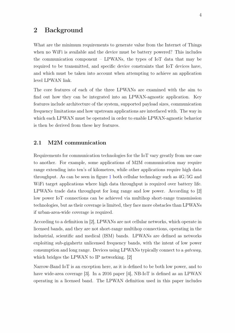
Technical limitations of the Sigfox system are payload size, messages per day anddownlinks per day. The up- and downlink payload limits of Sigfox are 12 bytes and8 bytes, respectively. Sigfox utilizes a pricing model in which there are four levelsof communication volume per day, presented in 1
The Platinum uplink limitation is a consequence of ETSI regulations used in Europe,citing a 1 % duty cycle limitation leading to 144 12-byte-payload Sigfox messages perday [9]. As the pricing model shows, the Sigfox LPWAN is designed for higher uplink
7
Subscription level Uplink / 24 h Downlink / 24h
One 1-2 0Silver 3-50 1Gold 51-100 2Platinum 101-140 4
Table 1: Sigfox subscription tiers [8].
frequency than downlink, and for transmitting small payloads, such as infrequentsensor data. Downlink transmissions to many end-nodes must be sent by the samegateway, which itself must stay within the same ETSI duty cycle limitations as theend-node. Transmitting high-bandwidth data such as images, audio or video is notpossible over the Sigfox network.
The Sigfox downlink transmission scheme [10] is as follows:
1. The end-node requests a downlink message by adding a downlink request flagto an uplink. The sequence is always initiated by the end-node.
2. The Sigfox Cloud runs a callback to the customer’s application server andgathers any downlink data available for the end-node.
3. In a few seconds, the downlink message is transmitted to the end-node.
With such a scheme, the end-node can not be activated remotely to perform anaction with low latency. The application must allow waiting until the next uplinkconnection to transmit data downlink to the end-node. The downlink HTTP re-sponse must be received by the Sigfox backend in under 20 seconds [9]. Also, witha maximum downlink data rate of 24 bytes per day, it is not possible to performfirmware Over-The-Air (FOTA) updates. This amount of data may, however beenough for example adjusting certain parameters of a device remotely.
2.4.3 Security
According to Sigfox’s paper on their approach to security [11], the Sigfox networkrelies heavily on their non-IP connection and limited bandwidth. The paper ar-gues that Sigfox devices are expected to only use their data link for implementingtheir default behaviour, and don’t allow for radically changing device behaviour.As the end-node can only ever contact Sigfox’s backend, the company has control

8
over where to forward the resulting IP traffic. Sigfox assures that data being sentover the air in both directions is error-checked, authenticated and protected againstreplay attacks, but is not encrypted and can thus be decoded by third parties. Au-thentication guarantees the proper origin of the message, either the end-node or theSigfox network.
Each Sigfox message received contains a sequence number identifying the message.A newly received sequence number is then compared to the ones last received bythe Sigfox network, and action is taken according to the gap’s severity. A warningis issued if there is any gap in the sequence number, and an error message alongwith interruption of message delivery if the gap is larger than the error limit of asubscription level. After 4096 messages the sequence number wraps around to 0.[12]
The Sigfox error limits for different subscription levels are presented in table 2. Theerror limits for all but the "One" subscription level translate to roughly three daysof continuous loss of coverage, assuming maximum subscription uplink throughput.The "One" subscription level will issue an error after 10 days under the same con-ditions.
Subscription level Error Limit
One 20Silver 150Gold 300Platinum 420
Table 2: Maximum difference in received Sigfox sequence numbers before messagesare not forwarded. [12]
2.4.4 Managing Power Consumption
Sigfox end-nodes initiate uplinks completely asynchronously, and do not implementlistening before transmitting [13]. This means that an end-node does not need touse radio power listening to the network before transmitting, may transmit imme-diately once it has ceased operating in a low-power state, and should receive anyqueued downlinks directly following the uplink transmission. The sequence allowsfor extremely low power consumption, as the end-node may fully turn off power totheir radios during a low-power state, effectively making the connectivity option notuse any power.

9
2.4.5 Configuration
The user interface for the backend system of the Sigfox network is displayed in figure2. Sigfox provides an abstracted link between end nodes and the Sigfox backend, soall settings wth regards to data transfer have to do with either the end-node or theuplink callbacks. So-called custom callbacks can modify the data in a limited way,add more information like date, time, location and SNR, and forward this data toa HTTP API or e-mail.
Figure 2: A screen capture of the device callback editor in Sigfox Backend.
The callback editor provides settings for at least:
• Type: Data/Service/Error – What to react to
• Type (continued): Uplink / BiDir – Is a downlink expected?
• Channel: Url / Batch-Url / E-mail – Where to forward data?
• Custom payload config – How to decode received bytes to variables for messageeditor

10
• Url pattern: Url to invoke, may include variables such as device name
• HTTP Method: POST / GET / PUT
• Headers: User-defined headers such as authorization
• Content-type
• Body: A field in which to write the message body, may include variables
The Sigfox Custom Format is a way to encode and decode data in few bytes, whilespecifying the data types used. It can decode a pre-determined sequence of bytes tosigned, unsigned integers, floats, character sequences and booleans. These variablesare then referenced according to pre-determined names.
2.5 LoRaWAN
LoRa is a proprietary wireless data communication technology developed by Semtech,for use in different unlicensed frequency bands worldwide. The technology consistsof a patented chirp spread spectrum (CSS) type modulation scheme and allows forconfigurable data rates. LoRaWAN is an open source medium access control (MAC)layer built on top of LoRa, defined by the LoRa Alliance consortium. LoRaWANoffers a bidirectional link between endpoint and gateway. [8]
2.5.1 Architecture
The architecture of a LoRaWAN system is depicted in figure 3. Endpoints broadcastto LoRaWAN gateways, which transparently forward the received messages overTCP/IP to their configured LoRaWAN network server. The network server thenfilters unwanted or duplicate packets. This architecture is said to simplify networkaccess for end nodes, and move all the complexity to the network server. [2]
LoRaWAN Application Servers provide part of the LoRaWAN functionality, andthese are not necessarily the same as the enterprise application servers which arereferred to as just application servers outside this chapter. The LoRaWAN Applic-ation Server can forward data to an enterprise application server which implementsbusiness logic [14].

11
IEEE Wireless Communications • October 201664
The gateways relay messages between the end devices and the NetServer according to the protocol architecture represented in Fig. 2. Unlike in standard cellular network systems, however, the end devices are not required to associate with a certain gateway to get access to the network, but only to the NetServer. The gateways act as a sort of relay/bridge and sim-ply forward to their associated NetServer all successfully decoded messages sent by any end device, after adding some information regard-ing the quality of the reception. The NetServ-er is hence in charge of filtering duplicate and unwanted packets, and of replying to the end devices by choosing one of the in-range gate-ways, according to some criterion (e.g., best radio connectivity). The gateways are thus total-ly transparent to the end devices, which are logically connected directly to the NetServer. Note that current full-fledged LoRa gateways allow the parallel processing of up to nine LoRa channels, where a channel is identified by a spe-cific sub-band and spreading factor.
This access mode greatly simplifies the man-agement of the network access for the end nodes, moving all the complexity to the Net-Server. Furthermore, the end nodes can freely move across cells served by different gateways without generating any additional signaling traf-fic in the access network or the core network. Finally, we observe that increasing the number of gateways that serve a certain end device will increase the reliability of its connection to the NetServer, which may be interesting for critical applications.
LoRa Device Classes: A distinguishing feature of the LoRa network is that it envisages three classes of end devices, Class A (for All), Class B (for Beacon), and Class C (for Continuously listening), each associated with a different oper-ating mode [17].
Class A defines the default functional mode of LoRa networks, and must be mandatorily supported by all LoRa devices. In a Class A net-work, transmissions are always initiated by the end devices in a totally asynchronous manner. After each uplink transmission, the end device will open (at least) two reception windows, wait-ing for any command or data packet returned by the NetServer. The second window is opened on a different sub-band (previously agreed on with the NetServer) in order to increase the resilience
against channel fluctuations. Class A networks are mainly intended for monitoring applications, where the data produced by the end devices have to be collected by a control station.
Class B has been introduced to decouple uplink and downlink transmissions. Class B end devices, indeed, synchronize with the NetServer by means of beacon packets, which are broad-cast by Class B gateways and can hence receive downlink data or command packets in specific time windows, irrespective of the uplink traffic. Therefore, Class B is intended for end devices that need to receive commands from a remote controller (e.g., switches or actuators).
Finally, Class C is defined for end devices without (strict) energy constraints (e.g., connect-ed to the power grid), which can hence keep the receive window always open.
LoRa MAC: The medium access control (MAC) layer, according to the LoRaWAN spec-ifications [17], is basically an ALOHA protocol controlled primarily by the LoRa NetServer. A description of the protocol is beyond the scope of this article and can be found in [17]. Overall, the LoRa MAC has been designed attempting to mimic as much as possible the interface of the IEEE 802.15.4 MAC toward the higher layers. The objective is to simplify the accommodation, on top of the LoRa MAC, of the major protocols now running on top of the IEEE 802.15.4 MAC, such as 6LoWPAN and Constrained Application Protocol (CoAP). A clear analogy is the authen-tication mechanism, which is taken directly from the IEEE 802.15.4 standard using the 4-octet message integrity code.
LoRa IP Connectivity: LoRaWAN employs the IEEE 64-bit extended unique identifier (EUI) to automatically associate IPv6 addresses with LoRa nodes. Therefore, IPv6/6LoWPAN protocols can be deployed on LoRaWAN net-works, thus enabling transparent interoperability with the IP-based world.
Security in LoRa: Security aspects are taken into account in the LoRaWAN specifications as well [17]. Several layers of encryption are employed, using:• A unique network key to ensure security at the
network layer• A unique application key to ensure end-to-end
security at the application layer, and finally • A device-specific key to secure the joining of a
node to the network.
Figure 1. LoRa system architecture.
End device End device
End device
End device
End deviceLoRa
radio links
End device
End device
End device
End device
LoRagateway
LoRagateway
IP connection IP connectionLoRa
NetServer
The NetServer is hence in charge of filtering duplicate and unwanted packets, and of replying to the end devices by choosing one of the in-range gateways, according to some crite-rion. The gateways are thus totally transparent to the end devices, which are logically con-nected directly to the NetServer.
Figure 3: The architecture of a LoRaWAN system from end-node to NetworkServer [2].
Each Lorawan device and application is addressed by a unique 64-bit identifier,known as DevEUI and AppEUI, respectively. The standard allows activating end-nodes with the network in two ways, via Over-The-Air-Activation (OTAA) or viaActivation By Personalization (ABP). ABP requires the device to be pre-loadedwith personalized credentials, while OTAA bootstraps the authentication from non-personalized credentials, so that all produced end-nodes may have identical firmware.
2.5.2 Transmission and End-node Specifics
LoRaWAN’s maximum payload size for both uplink and downlink transfers is between51 bytes and 222 bytes, depending on the spread factor used [15]. The spread factorof LoRaWAN determines the resulting Data Rate used [16], and affects the range[17]. Transmissions with different data rates do not interfere with each other [17],[18]. In addition to predetermined data rates the network can also adjust data ratesautomatically [19].
The LoRaWAN standard specifies three seperate device classes of end-nodes, map-ping to different operating modes: Class A (for All), Class B (for Beacon) and ClassC (for Continuously listening) [18]. These allow trading battery life for increasedconnectivity.
Class A is the default operating mode for all LoRaWAN devices, and as such im-plementing it is mandatory. Data transfer is always initiated asynchronously byend-node as an uplink, after which the end-node must open two receive windows.The receive window start delays must be set to the same values in both end-node

12
and network server. Class A enables the lowest power consumption, and is intendedfor devices that only require downlink data transfer immediately following an uplinktransfer. Asynchronous downlinks can be cached until the next scheduled uplink.[18]
Class B end-devices allow more downlink receive slots in a synchronous mannerat the price of higher power consumption. At pre-determined times, the end-nodeturns on it’s radio to open a receive window. To keep the end-node synchronizedwith network time, it also wakes up to open a ping slot when it roughly expectsone. The time between downlink application data transmissions, called the beaconperiod, is adjustable from 0.96 to 122.88 seconds. Transition decisions from ClassA to Class B are left to the application layer of the end-device, not the LoRaWANlayer. This means that for the server to turn on Class B operation of an end-node,it must wait for the Class A uplink, and only then send it’s downlink. Class Cdevices constantly listen for new transmissions, and have the lowest latency andhighest power consumption out of all Classes. They are specifically intended forapplications with ample power to use, and are not further described in this thesis.[18]
In addition to downlinks to a specific device, both Class B and Class C devices cansimultaneously receive the same message by so-called multicast downlinks, where agroup of devices temporarily share the same LoRaWAN encryption keys [18]. Thisnotably allows LoRaWAN devices to implement large downlink transfers such asfirmware OTA updates despite their limited payload sizes and duty cycle limitations[20].
Devices from both Class A and Class B enable power consumption low enough toenable battery powered devices [18]. Much like Sigfox, LoRaWAN achieves its lowestpower consumption when used in an application with mainly asynchronous uplinkdata transfer. Its usable payload sizes provide space for simultaneously transmittingGPS coordinates and other sensor data [5], but can not be reasonably used to sendraw audio or video data [15].
The LoRaWAN specification must follow local regulations, and in the EU 863-870band devices must adhere to the duty cycle limits specified in the ETSI EN 300220-2, as shown in table 3 on page 13. To maximize allowed air-time, an end-nodewould utilize different channels in order to increase its maximum duty cycle. Forexample, a specific LoRaWAN may use both the 868.0 – 868.6 MHz and 869.7 –870.0 MHz band, with a 1 % duty cycle limit each, together in order to increase

13
its total effective duty cycle limit to 2 %. Some LoRaWAN modules such as theRN2483 allow the user to specify duty cycle limits in order to ensure regulatorycompliance.
Frequency, MHz Limit, %
863.0 – 867.0 0.1868.0 – 868.6 1868.7 – 869.2 0.1869.4 – 869.65 10869.7 – 869.9 1
Table 3: EU863-870 ISM band duty cycle limits. [21]
The duty cycle limits of the used frequency bands determine the maximum allowedamount of transmissions per day from the gateway and the end-node. Using thelorawan_toa program [22] which is based on the formulae given in the LoRa ModemDesign Guide [23], it is possible to calculate practical transmission frequency limits.In order to send a LoRaWAN application payload of 10 bytes on LoRa spread factor12 in an EU band, the Time On Air (TOA) used is roughly 1483 ms. Assuming aduty cycle of 1 %, the next transmission may occur 148.3 seconds after the beginningof the first transmission. The maximum amount of transmission per day for thisexample would be 582. Using the fastest spread factor of 7, the TOA would be under62 ms, allowing for transmissions just over every six seconds. If using multiple EUsub-bands for communication, the transmission frequency could be still higher.
For LoRaWAN gateways, however, the situation is more complex. The gateway ornetwork of gateways has the same duty cycle capacity as end-nodes do, and mustserve both downlink data transfers and acknowledgements to uplink messages [15].With up to hundreds of end-nodes for each gateway, downlink communication isscarce, and this must be taken into account by the application.
2.5.3 Security
LoRaWAN messages are encrypted on multiple layers using unique network keys,application keys and device keys [2]. This multi-layered approach makes it possibleto transmit application payloads with end-to-end encryption, but still does not allowsafe communication over a malicious Network Server [18]. LoRaWAN devices arenot IP-connected, and can only communicate to IP networks via Network Servers,

14
which act as a similar strict firewall to the Sigfox networks backend system. Toensure data integrity, the PHY Payload contains a four byte Message Integrity Codecovering it’s other contents [18]. Additionally the Radio PHY layer utilizes a CRCfor both the LoRa Physical Header and the whole PHY Payload [18].
The LoRaWAN network protects against replayed join attempts to the network byusing a nonce in the join procedures. Regular data messages include a frame counterin the encrypted contents. Messages with the same frame counter repeated moretimes than agreed to by the end-node and network are ignored. [18]
2.5.4 Managing Power Consumption
LoRaWAN end-nodes can disable their radio interfaces in Class A and B operationin order to save power. The lowest overall power consumption can be achieved inClass A operation, where the devices radio interface is only activated once the devicehas data to transmit.
According to [16], LoRaWAN battery life is increased when using higher Data Rates(DR). This is because the higher bit rates allow for shorter transmissions. Powerconsumption was increased by a factor of up to 2.8 from DR 5 to DR 0 when using afive-minute uplink period. Decreasing payload size also decreased power consump-tion by a maximum factor of 1.59. The study also found that end-node powerconsumption was lower when using acknowledged transmissions. This, however wasassumed to not be the case for all hardware and to depend on low bit error rates.
Since the LoRaWAN DR affects battery life significantly, it should ideally be thehighest possible while ensuring no lost packets. A scheme with the objective tomaximize battery life and overall network capacity is the Adaptive Data Rate (ADR)defined in the LoRaWAN specification [18]. The ADR is negotiated between the end-node and the network in order to optimize DR for signal strength and battery lifein the current conditions.
LoRaWAN end-nodes may use Listen Before Talk, but it is not generally mandatory[15]. Under EU863-870 LoRaWAN uses duty-cycle limited transmissions, insteadof the alternative Listen Before Talk Adaptive Frequency Agility, to comply withETSI standards [17], [24]. This means that end-nodes in Europe may communicateimmediately following their termination of a low-power state.
Analysis of LoRaWAN:s Medium Access Control layer indicates that with the massiveamount of end-devices projected to be in use, there may be significant problems with

15
Feature LoRaServer Lorawan-server
HTTP Server Yes YesHTTP Client Yes YesMQTT Client Yes YesRX direct to database Yes, InfluxDB Yes, MongoDBWebsockets (RFC6455) No YesgRPC Yes NoAMQP 0-9-1 No Yes
Table 4: Comparison of most popular LoRaWAN network and application serverconnectivity. [14], [26]
collisions leading to reduced probability of messages being received [15], [25].
LoRaServer [26] and lorawan-server [14] are implementations of the Network andApplication Servers for LoRaWAN. Both lorawan-server and LoRaServer implement-ations allow for queueing of messages from an external application backend, whichthe Sigfox backend doesn’t provide. Table 4 summarizes the generally similar con-nectivity of the two implementations, with both supporting multiple connectionsto external servers and databases. Both LoRaServer and lorawan-server provideREST HTTP api’s for configuration and downlink data, can connect to externalHTTP api’s and function as MQTT clients, allowing for up- and downstream com-munication.
2.6 NB-IoT
Narrowband IoT (NB-IoT) is a wireless cellular standard released in 3GPP Release13 for providing wide-area coverage for IoT devices. Objectives that the standardwas built around include:
• very low cost,
• extended coverage,
• possibility for 10 year battery life with 5 Wh battery, and
• support for up to 50 000 devices per cell.
The standard, released in 2016 supports theoretical communication speeds of up to250 kbps for uplink and downlink. [27]

16
NB-IoT can be deployed by Mobile Network Operators (MNOs) in a gradual manner,coexisting with legacy GSM and LTE networks. This is possible as NB-IoT can bedeployed in three different schemes with respect to existing LTE carrier bands: fullyreplace a GSM carrier band, deploy within an existing LTE carrier band or deployin an LTE guard band. The options are intended to increase deployment flexibility.Finally, NB-IoT makes much use of the existing LTE design, significantly reducingthe development time and cost of NB-IoT products for existing LTE equipment andsoftware vendors. [3]
A 2011 paper reckoned that if the LTE architecture could be repurposed for machine-to-machine communications, the wide coverage of existing cellular networks maymean that cellular networks could well be an important route for M2M communic-ations [28]. NB-IoT can be deployed on existing cellular Base Transceiver Station’svia a software update [29]. NB-IoT is designed primarily for latency-insensitive ap-plications, but the standard still allows for a latency of under 10 seconds for casessuch as alarm signals [3].
2.6.1 Architecture
NB-IoT uses existing cellular network architecture to enable M2M communication,thus a short survey of current Long Term Evolution (LTE) network architecture isin order.
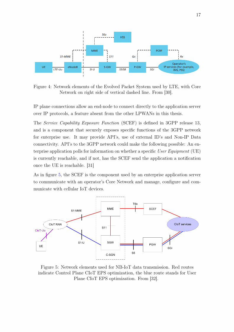
From the perspective of an LTE user the Evolved Packet System is that whichprovides the User Equipment (UE) with IP and voice connectivity to the internetand the operator’s services. To provide this the UE accesses the core network viaan evolved NodeB, as seen in figure 4. Evolved NodeB’s provide radio access in LTEnetworks, while the Core Network consists of multiple elements. The Core Networkelements, including the Serving Gateway (S-GW), the PDN Gateway (P-GW), theMME (Mobility Management Entity) and others work together to provide all theservices associated with modern LTE connectivity, including enforcing subscriberpolicies, IP allocation, settings Quality of Service (QoS) for different data, mobilitymanagement and more. [30]
From the perspective of an application developer NB-IoT supports two types ofroutes for communication: routes in Non-IP planes and routes in the IP plane [3]. Innon-IP plane communications the application server communicates to an end-nodevia a certain network operator’s API, which acts as a gateway to the NB-IoT devices.
17
Figure 4: Network elements of the Evolved Packet System used by LTE, with CoreNetwork on right side of vertical dashed line. From [30].
IP plane connections allow an end-node to connect directly to the application serverover IP protocols, a feature absent from the other LPWANs in this thesis.
The Service Capability Exposure Function (SCEF) is defined in 3GPP release 13,and is a component that securely exposes specific functions of the 3GPP networkfor enterprise use. It may provide API’s, use of external ID’s and Non-IP Dataconnectivity. API’s to the 3GPP network could make the following possible: An en-terprise application polls for information on whether a specific User Equipment (UE)is currently reachable, and if not, has the SCEF send the application a notificationonce the UE is reachable. [31]
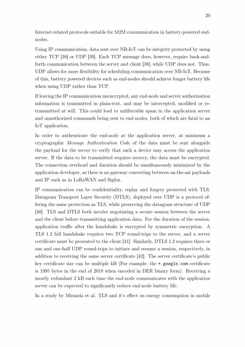
As in figure 5, the SCEF is the component used by an enterprise application serverto communicate with an operator’s Core Network and manage, configure and com-municate with cellular IoT devices.
Figure 5: Network elements used for NB-IoT data transmission. Red routesindicate Control Plane CIoT EPS optimization, the blue route stands for User
Plane CIoT EPS optimization. From [32].

18
2.6.2 Connectivity Options
According to the GSM Association, NB-IoT supports both SMS and multiple dataconnectivity options. SMS is not included in the minimum recommended featuresof the second edition of the GSMA NB-IoT Deployment Guide, and is not coveredin this thesis. The data connectivity options include:
• IP over Control Plane
• IP over User Plane
• Non-Ip over Control Plane
• Non-IP over User Plane.
All but Non-IP over User Plane are visualized in figure 5. Both IP and non-IP dataover control plane can travel RAN – MME – S-GW – P-GW – Application server,while the route RAN – MME – SCEF – Application server is only for Non-IP dataover Control Plane [33].
In LTE networks, user data is transported using both SMS and IP over User Plane.The traditional IP over User Plane directly via the S-GW and P-GW requires themost signalling out of the four data connectivity options. The other three were firstdefined in 3GPP Rel-13, and offer ways to balance the power consumption of end-nodes and their connectivity by utilizing different routes and optimizations throughthe core cellular network. The new Control Plane CIoT EPS optimisation definesboth IP and non-IP Control Plane options for sending user data and SMS messages.[33]
By utilising the Control Plane, the power consumption of sending reasonably smallmessages can be optimized by reducing the required signalling and total transmis-sion time. It is possible to further optimize power consumption by using non-IPtransmissions, as they allow use of custom protocols suited for the use case. If theamount of data to be transmitted is large, a User Plane connection may consumeless power. It is argued that using non-IP connections over the User Plane maynot reduce power consumption of the User Plane connection due to the User Planeconnections overhead. [33]
Conventional User Plane traffic must build a connection to the destination servereach time a packet is sent. User Plane CIoT EPS Optimization in NB-IoT, visualized

19
in blue in figure 5, allows the transfer of a sequence of packets on the User Planewith just a single built connection, leading to lower total overhead for larger datatransfers. Both IP and non-IP data are supported. [32]
2.6.3 Security (Non-IP)
NB-IoT inherits much of its security model from LTE networks, and is different fromSigfox and LoRaWAN in that it can also be used directly on the IP plane, with it’sbenefits and downsides. The communication security criteria which both are com-pared against in are: error checking, data confidentiality, possibility of forging dataor data being replayed in either direction. The security of Non-IP communicationconfigured via the SCEF is examined first, followed by a similar examination of thesecurity of IP-plane connections.
Specific requirements of security in MTC in 3GPP networks are defined in 3GPP TS133 187. It requires that any Machine-Type Communications (MTC) optimizationswithin the core network must not degrade security compared to non-MTC com-munications. Communication between the enterprise application server and SCEFmust implement integrity protection, replay protection and privacy protection, andconfidentiality protection should be used. In addition the SCEF should be able toverify the authorization of any application communicating with it. The specificationdefines optional procedures that include filtering unauthorized SMS messages thatmay be used for triggering devices, so that only the authentic application messagesare passed to the UE, restricting a specific SIM card to specific UEs and differenttypes of efficiently secured connections. [34]
Since the application server connects to the SCEF via IP protocols, the requirementsset in TS 133 187 are satisfied by a succesfully implemented TLS (Transport LayerSecurity) connection [35], along with authentication for applications. For commu-nication between the UE and the mobile network, the data is required to be integrity,confidentially and replay-protected from unauthorized parties when sending data onboth the Control Plane [36], [37] and the User Plane [36].
2.6.4 Security (IP)
If using NB-IoT in the IP domain, the end-node will directly contact the applicationserver, complicating the communication protocol choices for battery powered NB-IoT devices. The aim of this section is to go examine the various Internet and
20
Internet-related protocols suitable for M2M communication in battery-powered end-nodes.
Using IP communication, data sent over NB-IoT can be integrity protected by usingeither TCP [38] or UDP [39]. Each TCP message does, however, require back-and-forth communication between the server and client [38], while UDP does not. Thus,UDP allows for more flexibility for scheduling communication over NB-IoT. Becauseof this, battery powered devices such as end-nodes should achieve longer battery lifewhen using UDP rather than TCP.
If leaving the IP communication unencrypted, any end-node and server authorizationinformation is transmitted in plain-text, and may be intercepted, modified or re-transmitted at will. This could lead to unfilterable spam in the application serverand unauthorized commands being sent to end-nodes, both of which are fatal to anIoT application.
In order to authenticate the end-node at the application server, at minimum acryptographic Message Authentication Code of the data must be sent alongsidethe payload for the server to verify that such a device may access the applicationserver. If the data to be transmitted requires secrecy, the data must be encrypted.The connection overhead and duration should be simultaneously minimized by theapplication developer, as there is no gateway converting between on-the-air payloadsand IP such as in LoRaWAN and Sigfox.
IP communication can be confidentiality, replay and forgery protected with TLS.Datagram Transport Layer Security (DTLS), deployed over UDP is a protocol of-fering the same protection as TLS, while preserving the datagram structure of UDP[40]. TLS and DTLS both involve negotiating a secure session between the serverand the client before transmitting application data. For the duration of the session,application traffic after the handshake is encrypted by symmetric encryption. ATLS 1.2 full handshake requires two TCP round-trips to the server, and a servercertificate must be presented to the client [41]. Similarly, DTLS 1.2 requires three orone and one-half UDP round-trips to initiate and resume a session, respectively, inaddition to receiving the same server certificate [42]. The server certificate’s publickey certificate size can be multiple kB (For example, the *.google.com certificateis 1995 bytes in the end of 2018 when encoded in DER binary form). Receiving amostly redundant 2 kB each time the end-node communicates with the applicationserver can be expected to significantly reduce end-node battery life.
In a study by Miranda et al. TLS and it’s effect on energy consumption in mobile
21
devices using both WLAN and 3G was tested. They found that for the smallesttested transaction sizes of 1 kB in a 3G network, 80 - 90 % of the energy consumedby the device was spent in the TLS handshake [43]. A transaction size of 1 kB ismuch larger than allowed for Sigfox and LoRaWAN, meaning that for encryptingpayloads of under 1 kB, NB-IoT end-nodes using TLS encrypted IP protocols wouldspend a very significant amount of energy initiating secure sessions, and hardly anyfor transmitting application payloads.
One client authorization scheme in TLS is to use a client public key certificate [41].The initial handshake contains a challenge in which the client can cryptographicallyprove it’s identity to the server. Another scheme is to rely on the eavesdroppingprotection of TLS and DTLS and have the end-node provide a unique secret on theapplication level to prove its identity. For example when using HTTPS this couldbe achieved by using basic access authentication [44], a simple user/password pair.A client certificate offers the possibility to update the certificate without the serverlosing trust (via Certificate Authorities), but requires the certificate to be sent bythe client in each initial TLS/DTLS handshake, leading to more transmitted data.The authentication is then valid for the whole session. A user/password pair sentin every request may require less overhead for short sessions with few requests, butthe pair can not be updated without server-side changes.
The TLS-PSK cipher suites are a solution within TLS to support authenticationvia symmetric Pre-Shared Keys (PSK), known only by the client and the server.Originally defined by the RFC 4279 as the cipher suites beginning with TLS_PSK,benefits of the TLS-PSK cipher suites are the fact that there is no need for costly-to-compute public-key operations and key management can be simplified greatly.The RFC document specifically mentions clients with pre-configured machine-to-machine connections as a suitable use case. The TLS handshake when using PSKsalso requires much less data to be transmitted back and forth, as no certificates aretransferred. [45]
PSK cipher suites are also part of the DTLS specification [40], [46], offering the samebenefits of lower bandwidth use and less costly encryption and decryption operations[46]. The PSK handshake in DTLS 1.3 allows the client to send application dataafter just one UDP round-trip, without transferring a server or client certificateeither way. [40].

22
2.6.5 Managing Power Consumption
Two modes of communication in cellular networks have been recently introduced bythe 3GPP in order to enable optimization of power consumption in cellular networks.
PSM, introduced in 3GPP Release 12, is designed to enable IoT devices to achievethe specified design goal of 10 year battery life. Turning the radio of the end-node off conserves the most battery, and has always been an option in cellularnetworks. On subsequent wake up, the device would need to register again withthe network, leading to increased power consumption over the lifetime of the device.PSM configurations enable the end-node to stay attached to the network for a setamount of time without any radio transmissions. [33]
The applied PSM configuration is negotiated jointly by the UE and the network. Adevice may initiate PSM by providing two timers, T3412 and T3324 to the network.If accepted by the network, the difference between these two timers defines the PSMcycle during which the UE may keep it’s radio powered off. The UE is also allowedto broadcast uplink data before the expiration of the PSM cycle, for example to sendinformation of an alarm condition. PSM cycle time can reach up to approximately413 days. A feature that is recommended by the GSMA is to store downlink packetsreceived by the network during PSM, and transmit them once an uplink transmissionoccurs. [33]
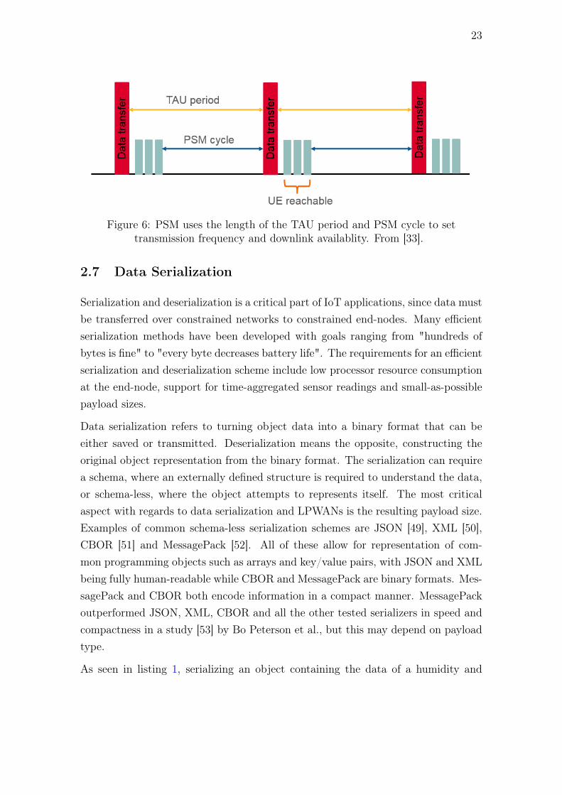
More specifically, Active Timer T3324 controls how long the UE is reachable by thenetwork after the data transfer period. This is shown in figure 6 on page 23 as theUE reachable period. The Tracking Area Update (TAU) timer T3412 controls theperiod between the UE signaling it’s existence on the network. [47]
According to a recent Master’s thesis, the average power consumption of the BG96cellular modem in NB-IoT mode during the data transfer period was roughly 247mW for 12 s for one Finnish MNO, and 218 mW for 15 s for the other [48]. Theexperiment fails to specify the values used for timers T3412 and T3324. The powerconsumption of the following network idle period were roughly 102 mW for 32 s and66 mW for 43 s. Since the length of the idle period should be set by timer T3324, ashorter idle period duration should reduce total power consumption.
23
Figure 6: PSM uses the length of the TAU period and PSM cycle to settransmission frequency and downlink availablity. From [33].
2.7 Data Serialization
Serialization and deserialization is a critical part of IoT applications, since data mustbe transferred over constrained networks to constrained end-nodes. Many efficientserialization methods have been developed with goals ranging from "hundreds ofbytes is fine" to "every byte decreases battery life". The requirements for an efficientserialization and deserialization scheme include low processor resource consumptionat the end-node, support for time-aggregated sensor readings and small-as-possiblepayload sizes.
Data serialization refers to turning object data into a binary format that can beeither saved or transmitted. Deserialization means the opposite, constructing theoriginal object representation from the binary format. The serialization can requirea schema, where an externally defined structure is required to understand the data,or schema-less, where the object attempts to represents itself. The most criticalaspect with regards to data serialization and LPWANs is the resulting payload size.Examples of common schema-less serialization schemes are JSON [49], XML [50],CBOR [51] and MessagePack [52]. All of these allow for representation of com-mon programming objects such as arrays and key/value pairs, with JSON and XMLbeing fully human-readable while CBOR and MessagePack are binary formats. Mes-sagePack and CBOR both encode information in a compact manner. MessagePackoutperformed JSON, XML, CBOR and all the other tested serializers in speed andcompactness in a study [53] by Bo Peterson et al., but this may depend on payloadtype.
As seen in listing 1, serializing an object containing the data of a humidity and

24
temperature sensor with JSON in results in a payload size of 145 bytes (whitespaceremoved), which is twelve times the allowed Sigfox uplink payload size. The examplelisting includes a channel value in order to seperately identify multiple sensors of thesame type in one payload, for example indoor and outdoor temperature. Serializingthe same data structure with MessagePack yields a payload size of 117 bytes forthe same data. This is an improvement, but is still roughly ten times the size ofthe maximum allowed Sigfox payload, and double the maximum payload size ofLoRaWAN with the slowest data rate.
{"device": "Example","data": [{"type": "temperature","unit": "C","channel": 1,"value": 20.50
}, {"type": "humidity","unit": "%","channel": 3,"value": 50.5
}]}
Listing 1: Example of explicit end-node sensor data. Channel of data allows formultiple readings of the same type to be referenced.
A model of how to compress sensor measurement data has been defined by theIETF as Sensor Measurement Lists in the RFC 8428. SenML is a data model,and serializations of it are provided for JSON, CBOR, XML and Efficient XMLInterchange (EXI). SenML compresses the data by reducing redundant data in listsof sensor measurements. It supports measurement lists for values at different relativeand absolute times, different sensors and actuators, completely different devices. [54]
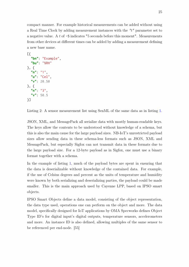
A simple example of a SenML-modeled JSON serialization is shown in listing 2.A base name "bn" and base unit "bu" are used to reduce redundant data. TheJSON serialization less whitespace requires 78 bytes, and a CBOR serialization ofthe same data requires 46 bytes – a decrease of 71 bytes in payload size compared tolisting 1 MessagePacked. In the case of a single measurement SenML achieves thisdecrease mostly due to reducing key lengths to one or two characters. Where SenMLshines is when data from multiple devices or timepoints are to be expressed in a
25
compact manner. For example historical measurements can be added without usinga Real Time Clock by adding measurement instances with the "t" parameter set toa negative value. A t of -5 indicates "5 seconds before this moment". Measurementsfrom other devices at different times can be added by adding a measurement defininga new base name.
[{"bn": "Example","bu": "%RH"
}, {"n": "1","u": "Cel","v": 20.50
}, {"n": "3","v": 50.5
}]
Listing 2: A sensor measurement list using SenML of the same data as in listing 1.
JSON, XML, and MessagePack all serialize data with mostly human-readable keys.The keys allow the contents to be understood without knowledge of a schema, butthis is also the main cause for the large payload sizes. NB-IoT’s unrestricted payloadsizes allow sending data in these schema-less formats such as JSON, XML andMessagePack, but especially Sigfox can not transmit data in these formats due tothe large payload size. For a 12-byte payload as in Sigfox, one must use a binaryformat together with a schema.
In the example of listing 1, much of the payload bytes are spent in ensuring thatthe data is deserializable without knowledge of the contained data. For example,if the use of Celsius degrees and percent as the units of temperature and humiditywere known by both serializing and deserializing parties, the payload could be madesmaller. This is the main approach used by Cayenne LPP, based on IPSO smartobjects.
IPSO Smart Objects define a data model, consisting of the object representation,the data type used, operations one can perform on the object and more. The datamodel, specifically designed for IoT applications by OMA Specworks defines ObjectType ID’s for digital input’s digital outputs, temperature sensors, accelerometersand more. An instance ID is also defined, allowing multiples of the same sensor tobe referenced per end-node. [55]
26
Hex Stands for Result
0x01 Channel 010x67 Temperature sensor Temperature (Channel 1): 20.5 °C0x00CD Value of 205
0x03 Channel 030x68 Humidity sensor Humidity (Channel 3): 50.5 %0x65 Value of 101
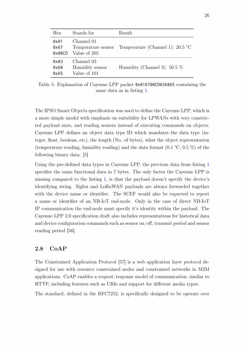
Table 5: Explanation of Cayenne LPP packet 0x016700CD036865 containing thesame data as in listing 1.
The IPSO Smart Objects specification was used to define the Cayenne LPP, which isa more simple model with emphasis on suitability for LPWANs with very constric-ted payload sizes, and reading sensors instead of executing commands on objects.Cayenne LPP defines an object data type ID which mandates the data type (in-teger, float, boolean, etc), the length (No. of bytes), what the object representation(temperature reading, humidity reading) and the data format (0.1 °C, 0.5 %) of thefollowing binary data. [5]
Using the pre-defined data types in Cayenne LPP, the previous data from listing 1specifies the same functional data in 7 bytes. The only factor the Cayenne LPP ismissing compared to the listing 1, is that the payload doesn’t specify the device’sidentifying string. Sigfox and LoRaWAN payloads are always forwarded togetherwith the device name or identifier. The SCEF would also be expected to reporta name or identifier of an NB-IoT end-node. Only in the case of direct NB-IoTIP communication the end-node must specify it’s identity within the payload. TheCayenne LPP 2.0 specification draft also includes representations for historical dataand device configuration commands such as sensor on/off, transmit period and sensorreading period [56].
2.8 CoAP
The Constrained Application Protocol [57] is a web application layer protocol de-signed for use with resource constrained nodes and constrained networks in M2Mapplications. CoAP enables a request/response model of communication, similar toHTTP, including features such as URIs and support for different media types.
The standard, defined in the RFC7252, is specifically designed to be operate over
27
datagram transports, mainly UDP. This is a key underlying difference to HTTP,which operates over a connection-based protocol such as TCP. CoAP can be usedwith DTLS to allow secure communication over UDP, and also used over othertransports such as SMS, TCP and SCTP [57].
The fundamentals of CoAP consist of the messaging model, and the request/responsemodel. The messaging models concern is exchanging messages over UDP betweenendpoints, and does not define servers or clients. The request/response model defineshow a server and a client interact with each other. We will examine the messagingmodel first.
The CoAP messaging model has two features:
• Stop-and-wait retransmission reliability with exponential back-off for Confirm-able messages.
• Duplicate detection for both Confirmable and Non-Confirmable messages.
CoAP defines four types of messages: Confirmable (CON), Non-Confirmable (NON),Acknowledgement (ACK) and Reset (RST). The Confirmable message type is usedfor reliably transmitted messages. The recipient of such a message must eitherrespond with an ACK (to acknowledge) or a RST (to indicate that the messagecould not be processed properly). A NON message is a one-way message, and if amessage does not make it to the recipient, neither the sender nor the receiver willknow without using out-of-band data.
CoAP requests and responses are carried in CoAP messages, and include either aMethod Code or a Response Code, respectively. The Method Codes are listed intable 6. The Methods map roughly to HTTP methods, but are specifically definedfor CoAP. Response Codes belong to class 2, 4 or 5, indicating Success, Client Errorand Server Error, respectively. Response Codes are written in the format C.XX, withC as Class of code, and XX specifying the details of the response code.
CoAP also specifies how the message type influences client and server interaction. ACON request requires an ACK within ACK_TIMEOUT, which is by default 2 seconds.Since replying with an ACK and immediately sending the actual response to therequest would be wasteful, CoAP specifies that responses may be sent within thesame PDU (Protocol Data Unit) as an ACK. An example of this kind of exchangeis shown in figure 7. The optimization, called piggybacking, allows a request andresponse pair to occupy only two PDUs. In case either of the messages are lost,

28
Method Short Description Safe Idempotent
GET Retrieves a represetation of the inform-ation that correspond to the resourceidentied in the request URI.
Yes Yes
POST A request to process the enclosed data. - -
PUT A request to create or update the re-source with the enclosed representa-tion.
- Yes
DELETE A request to delete the resource at theURI.
- Yes
Table 6: List of CoAP Methods. Safe methods do not alter server state.
the standard retransmission scheme for CoAP is used until the client receives thepiggybacked response. [57]
If the client is under a limitation to only send one message to the server, but wouldstill like to receive a response, the request may be made with a NON message.In this case the response is also sent using a NON message. This scenario couldoccur if for example a cellular NB-IoT device must conserve power, and uplinktransmissions consume significantly more power than receiving. When compared toa CON request, the client does lose the information on whether the request or theresponse was lost in transit, but gains more control over it’s own power consumption.This could be very significant for the end-nodes battery life when it is experiencinga very lossy network.
Client Server
POST, CON2.04 Changed, ACK
Figure 7: A Confirmable request which receives a response piggy-backed to anACK message.
CoAP options represent optional or default request and response information, andsome options provide similar functionality to what HTTP headers provide. Ex-amples of CoAP options include payload content-types and accepted content-types.CoAP URIs paths are also encoded as options. [57]
29
Client Server
POST, NON2.04 Changed, NON
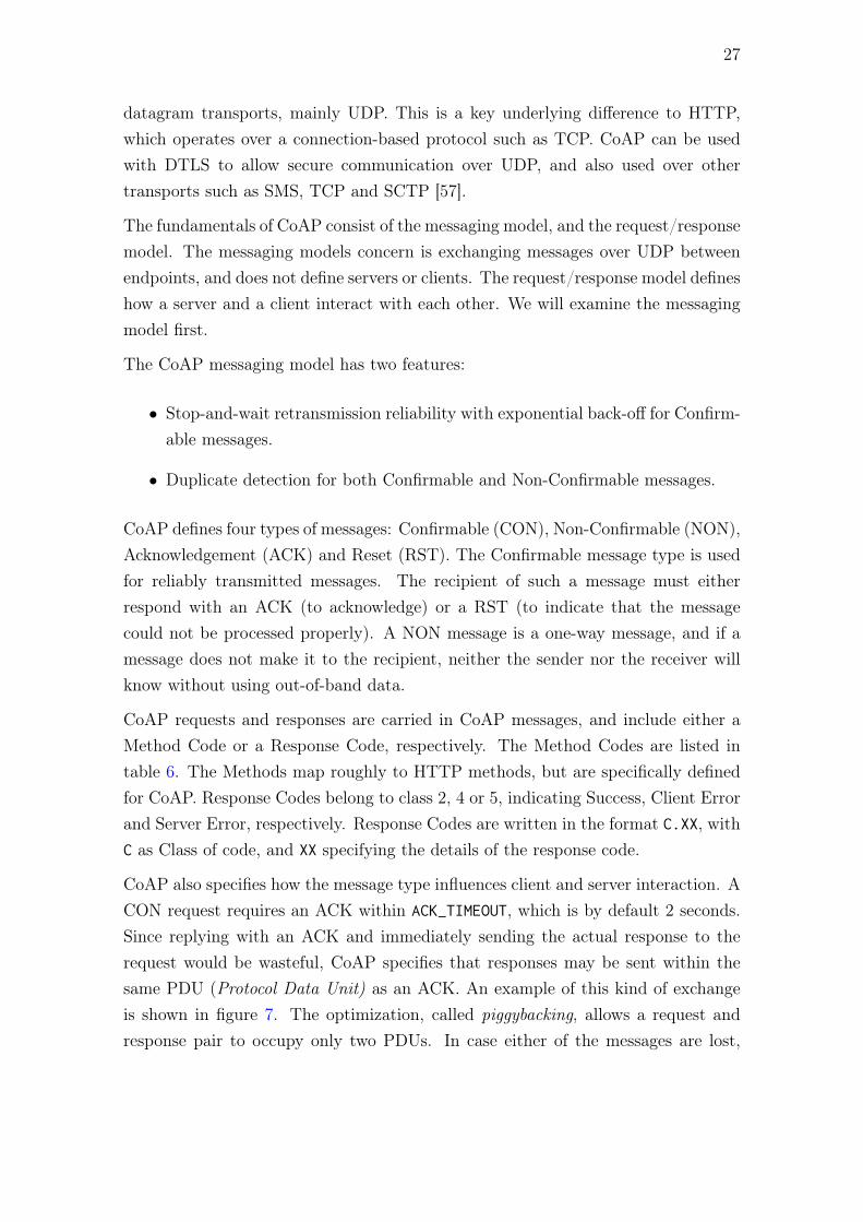
Figure 8: A Non-Confirmable request which receives a NON response.
As CoAP is designed for constrained networks, it provides an option for the clientto request that no response is sent back to it. The No-Response option, specifiedin RFC 7967 allows the client to specify for which response classes it does notrequest a response. If all response classes are not requested, the client should ceaselistening for any responses to the specific request. If there is only one request active,the client no longer has any obligations to the server, thus the communication isentirely one-way. [58]
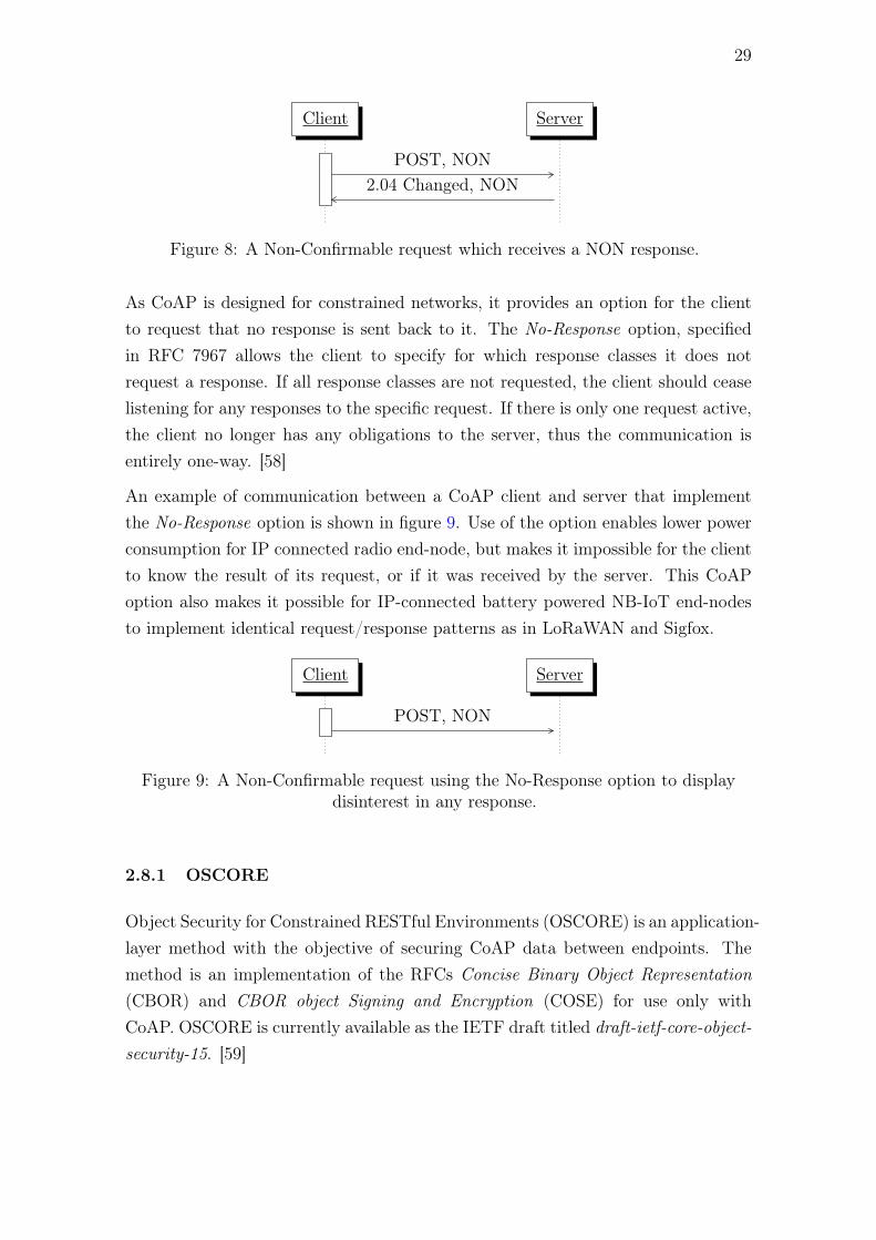
An example of communication between a CoAP client and server that implementthe No-Response option is shown in figure 9. Use of the option enables lower powerconsumption for IP connected radio end-node, but makes it impossible for the clientto know the result of its request, or if it was received by the server. This CoAPoption also makes it possible for IP-connected battery powered NB-IoT end-nodesto implement identical request/response patterns as in LoRaWAN and Sigfox.
Client Server
POST, NON
Figure 9: A Non-Confirmable request using the No-Response option to displaydisinterest in any response.
2.8.1 OSCORE
Object Security for Constrained RESTful Environments (OSCORE) is an application-layer method with the objective of securing CoAP data between endpoints. Themethod is an implementation of the RFCs Concise Binary Object Representation(CBOR) and CBOR object Signing and Encryption (COSE) for use only withCoAP. OSCORE is currently available as the IETF draft titled draft-ietf-core-object-security-15. [59]
30
OSCORE is implemented with pre-shared keys, and is secured to the extent that stillallows CoAP proxies to function. OSCOREs properties guarantee end-to-end en-cryption, integrity, replay protection, and binding of response to request. It securesthe request method, the requested resource and the message payload but does notprotect the CoAP messaging layer or the CoAP Token. It supports the No-ResponseCoAP option among other options of CoAP. [59]
In their comparison of OSCORE and different DTLS, TLS versions, J. Mattson et al.[60] found that of the UDP protocols, DTLS 1.2 has a notably higher overhead com-pared to DTLS 1.3 and OSCORE. DTLS 1.3 overhead was slightly larger than thatof OSCORE, and similar when using the short header format of DTLS 1.3. However,the short header format can only be used once the DTLS handshake is complete [40],so it is not of use in cases when the session only lasts one request/response pair.
2.9 Docker
Docker [61] is a container platform, allowing applications to function within a closed-off virtual environment, the container. The applications within the containers areseparated from the host system with regards to the other processes that they canobserve, their network stack and their capability to use up CPU, memory and diskI/O resources [62]. In docker they share the host operating system’s (OS’s) kernel,and so are not quite as secure as full virtual machines [63]. Luckily the seperationof the operating systems applications ’see’ is useful for more than security.
Docker containers are created from images. An image is a snapshot of an environ-ment, and may include from basic functionality, such as only a bare OS with onlyfundamental tools, to a fully functional cloud application. A docker image is con-structed in layers by applying various commands (such as a command to install aweb server application, or add a file) to a base image. This process can be managedby scripts, allowing accurate control of the final environment that an applicationwill experience. This leads to repeatability and portability. [63]
31
3 Environment and Requirements
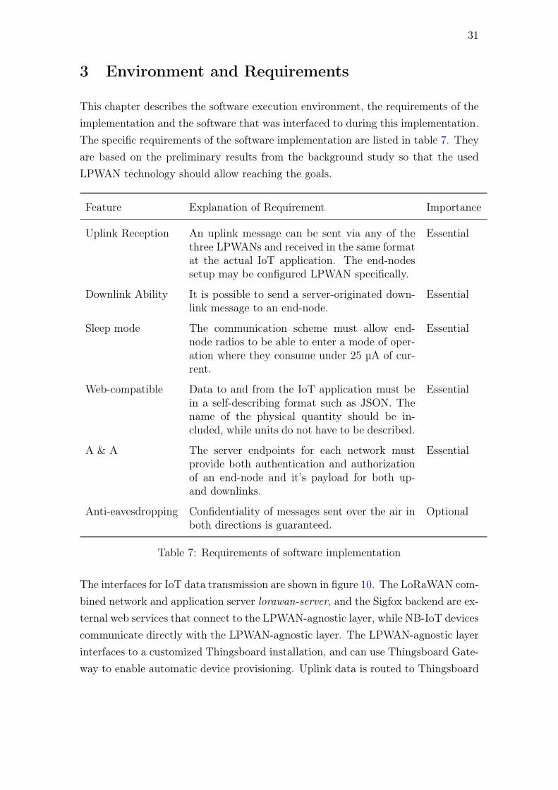
This chapter describes the software execution environment, the requirements of theimplementation and the software that was interfaced to during this implementation.The specific requirements of the software implementation are listed in table 7. Theyare based on the preliminary results from the background study so that the usedLPWAN technology should allow reaching the goals.
Feature Explanation of Requirement Importance
Uplink Reception An uplink message can be sent via any of thethree LPWANs and received in the same formatat the actual IoT application. The end-nodessetup may be configured LPWAN specifically.
Essential
Downlink Ability It is possible to send a server-originated down-link message to an end-node.
Essential
Sleep mode The communication scheme must allow end-node radios to be able to enter a mode of oper-ation where they consume under 25 µA of cur-rent.
Essential
Web-compatible Data to and from the IoT application must bein a self-describing format such as JSON. Thename of the physical quantity should be in-cluded, while units do not have to be described.
Essential
A & A The server endpoints for each network mustprovide both authentication and authorizationof an end-node and it’s payload for both up-and downlinks.
Essential
Anti-eavesdropping Confidentiality of messages sent over the air inboth directions is guaranteed.
Optional
Table 7: Requirements of software implementation
The interfaces for IoT data transmission are shown in figure 10. The LoRaWAN com-bined network and application server lorawan-server, and the Sigfox backend are ex-ternal web services that connect to the LPWAN-agnostic layer, while NB-IoT devicescommunicate directly with the LPWAN-agnostic layer. The LPWAN-agnostic layerinterfaces to a customized Thingsboard installation, and can use Thingsboard Gate-way to enable automatic device provisioning. Uplink data is routed to Thingsboard

32
Gateway, and downlink data is available directly from Thingsboard via RPC callsconfigured from within Thingsboard. The Sigfox platform version currently in useis SIGFOX Cloud 7.8, supporting the Sigfox v2 API.
Lorawan-server
Sigfox backend
Device connected via
NB-IoT
ThingsboardGateway
Thingsboard
LPWAN-agnostic layer
Figure 10: Operating environment for the application. Blue arrows denote uplinkconnection routes, orange arrows denote downlink routes.
3.1 End-nodes
A goal of the end-nodes used with the LPWAN-agnostic layer is to allow efficientdesign re-use between different applications. This is achieved in part by relying ona common host processor, and optionally common sensors. The LPWAN moduleused can then be chosen to suit the application requirements. The host processor hascapabilities that correspond to the low end of Class 1 per the RFC7228 [64]. Thismeans that the host processor may be able to support eg. CoAP communication, buta full-featured HTTP, TLS and message parsing stack on the host processor is notpossible. Particularly NB-IoT modules do implement high-level API’s for protocolssuch as HTTPS or MQTTS, thus relieving the requirement for implementing thesestacks on the host processor.
3.2 LPWAN-Specific Hardware and Software
LoRaWAN gateways, network and application servers used in this implementationare:
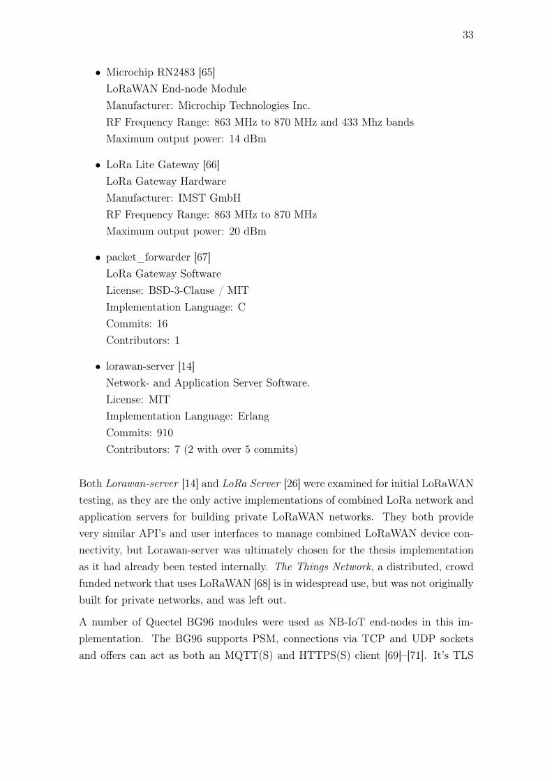
33
• Microchip RN2483 [65]LoRaWAN End-node ModuleManufacturer: Microchip Technologies Inc.RF Frequency Range: 863 MHz to 870 MHz and 433 Mhz bandsMaximum output power: 14 dBm
• LoRa Lite Gateway [66]LoRa Gateway HardwareManufacturer: IMST GmbHRF Frequency Range: 863 MHz to 870 MHzMaximum output power: 20 dBm
• packet_forwarder [67]LoRa Gateway SoftwareLicense: BSD-3-Clause / MITImplementation Language: CCommits: 16Contributors: 1
• lorawan-server [14]Network- and Application Server Software.License: MITImplementation Language: ErlangCommits: 910Contributors: 7 (2 with over 5 commits)
Both Lorawan-server [14] and LoRa Server [26] were examined for initial LoRaWANtesting, as they are the only active implementations of combined LoRa network andapplication servers for building private LoRaWAN networks. They both providevery similar API’s and user interfaces to manage combined LoRaWAN device con-nectivity, but Lorawan-server was ultimately chosen for the thesis implementationas it had already been tested internally. The Things Network, a distributed, crowdfunded network that uses LoRaWAN [68] is in widespread use, but was not originallybuilt for private networks, and was left out.
A number of Quectel BG96 modules were used as NB-IoT end-nodes in this im-plementation. The BG96 supports PSM, connections via TCP and UDP socketsand offers can act as both an MQTT(S) and HTTPS(S) client [69]–[71]. It’s TLS

34
implementation does not support the TLS-PSK cipher suites. The module does notprovide an interface for acting as a CoAP client or server.
The NB-IoT services of two mobile network operators were used in testing, referredto as operator A and operator B. Neither have support for SCEF-based access, andneither specifies a seperate control plane APN. Operator A uses LTE band 20 at800 MHz as it’s primary band, with a fallback to band 3 at 1800 MHz. Operator Buses bands 3 and 20 for NB-IoT coverage.
The Sigfox modules used in the implementation were the WSSFM10R1 by WiSOLCo. for use within ETSI regulations.
3.3 Server Runtime Environment and IoT Application
The application will be initially deployed on a single server running Ubuntu 16.04.There are no requirements for this stage of development to support clustered use.Docker and docker-compose are available on the server, and for this project, they arethe preferred way to deploy the application. The IoT application to be interfaced toby the LPWAN-agnostic layer is Thingsboard 1.4.0. Thingsboard [72] is a full IoTplatform, offering interfaces to many IoT protocols and support for many formatsof data.

35
4 Implementation
The communication scheme chosen for the system was one based on asynchronousuplink connectivity, with an optional synchronous downlink connectivity period.This communication scheme was chosen as it is the only communication schemesupported by all three LPWANs. Additionally it enables extremely low end-nodepower consumption due to minimal time-on-air. Meaningful application payloadssuch as sensor values sent over the different LPWANs are generally possible to fitinto the 12 bytes of a Sigfox uplink transmission. The server system can be madecapable of accepting larger payloads if receiving messages from either LoRaWANor NB-IoT end-nodes. In order to achieve LPWAN-agnostic communications fordownlink transmissions the size of downlink messages to all end-nodes must belimited to the 8 bytes supported by Sigfox.
The serialized application payloads follow a custom schema format similar to Cay-enne LPP, with application-specific headers specifying the following data’s interpret-ation. The headers specify the represented data type (eg. integer, float, string), theserialization format and the unit of the value specified. The meaning of each headershould be known in advance to both the sender and the receiver. This is simplyachieved at the server end, as it will receive constant updates. Commands sent tothe end-node must be verified to be valid, and for now the number of commandsparsed by the end-node is very limited.
4.1 Sigfox
Since the Sigfox backend does not queue downlink messages, the LPWAN-agnosticlayer must queue the Sigfox downlink messages, visible in figure 11. The queue isimplemented as a PostgreSQL table, with each row containing a Sigfox end-nodeID’s and the downlink messages queued for it, if any.
Asynchronous downlink messages are received from Thingsboard as RPC commandsvia an MQTT interface. Once an asynchronous downlink message is received, it isencoded from JSON into the application payload, with a maximum size of 8 bytes.This payload is then stored in the downlink queue. If a new command is received inThingsboard, it is merged with the existing queued downlink message. The queuedepth for Sigfox is limited to only one downlink message. The logic to implementsmart merging of application payloads is out of the thesis’ scope.
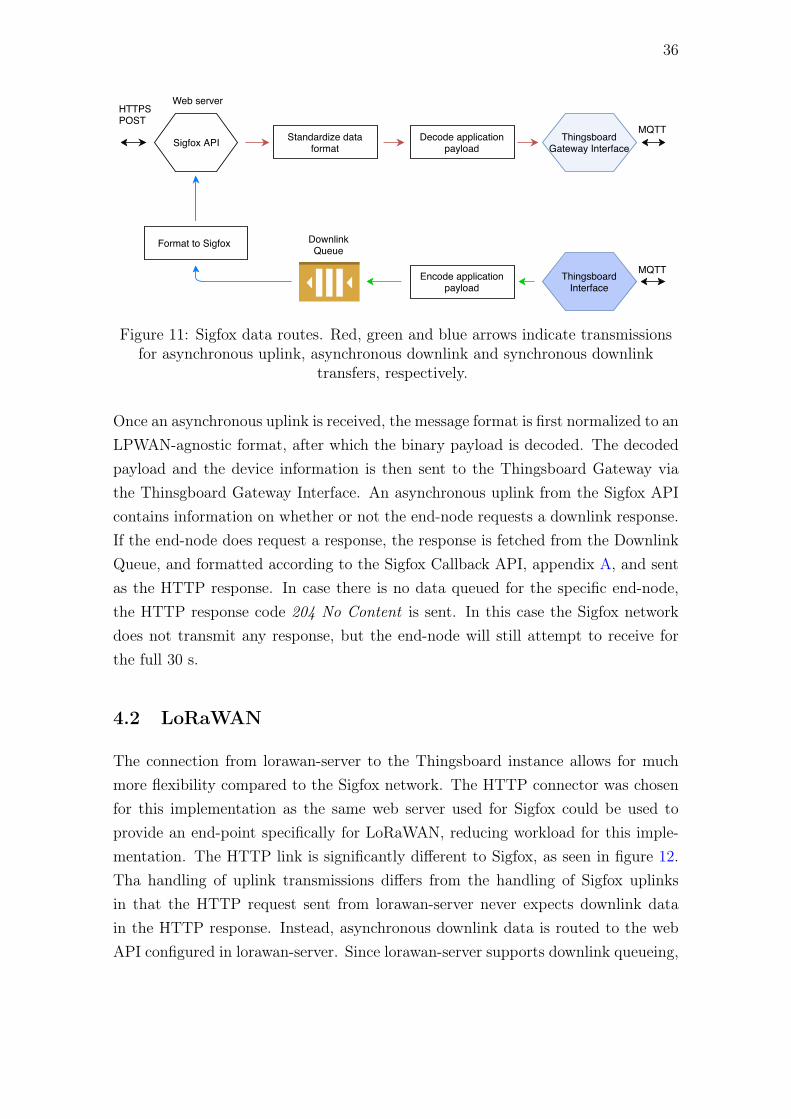
36
DownlinkQueue
MQTT
HTTPS POST
Sigfox API
Web server
Standardize dataformat
Decode applicationpayload
ThingsboardGateway Interface
ThingsboardInterface
MQTT
Format to Sigfox
Encode applicationpayload
Figure 11: Sigfox data routes. Red, green and blue arrows indicate transmissionsfor asynchronous uplink, asynchronous downlink and synchronous downlink
transfers, respectively.
Once an asynchronous uplink is received, the message format is first normalized to anLPWAN-agnostic format, after which the binary payload is decoded. The decodedpayload and the device information is then sent to the Thingsboard Gateway viathe Thinsgboard Gateway Interface. An asynchronous uplink from the Sigfox APIcontains information on whether or not the end-node requests a downlink response.If the end-node does request a response, the response is fetched from the DownlinkQueue, and formatted according to the Sigfox Callback API, appendix A, and sentas the HTTP response. In case there is no data queued for the specific end-node,the HTTP response code 204 No Content is sent. In this case the Sigfox networkdoes not transmit any response, but the end-node will still attempt to receive forthe full 30 s.
4.2 LoRaWAN
The connection from lorawan-server to the Thingsboard instance allows for muchmore flexibility compared to the Sigfox network. The HTTP connector was chosenfor this implementation as the same web server used for Sigfox could be used toprovide an end-point specifically for LoRaWAN, reducing workload for this imple-mentation. The HTTP link is significantly different to Sigfox, as seen in figure 12.Tha handling of uplink transmissions differs from the handling of Sigfox uplinksin that the HTTP request sent from lorawan-server never expects downlink datain the HTTP response. Instead, asynchronous downlink data is routed to the webAPI configured in lorawan-server. Since lorawan-server supports downlink queueing,

37
asynchronous downlink transmission from Thingsboard are encoded, formatted andthen sent immediately to the lorawan-server web API.
MQTT
HTTPS POST
LoRaWAN API
Web server
Standardize dataformat
Decode applicationpayload
ThingsboardGateway Interface
ThingsboardInterface
MQTTFormat to LoRaWAN -server JSON
Encode applicationpayload
HTTPS POST
Generate HTTP Request
Figure 12: LoRaWAN data routes. Arrow colours as in figure 11.
4.3 NB-IoT
The NB-IoT end-nodes currently implement communication via IP connectivity, andSCEF support from Finnish operators is missing as of October 2018. This leads itto be the only LPWAN class in which payload encryption and device identity mustbe implemented on top of the communication protocol.
4.3.1 Security
Since reducing the time-on-air of the NB-IoT end-node results in direct battery lifeimprovements, UDP was chosen to be used on the transport layer, and CoAP asthe application layer protocol. Because of the essential A & A requirement specifiedin table 7, the data sent over CoAP must be at minimum protected by a messageauthentication code. DTLS provides much more, namely being specifically designedto prevent eavesdropping, tampering and message forgery, but in this case comeswith some drawbacks. For example, MbedTLS and application logic could notreliably fit in the flash size of the Class 1 end-node processor, and the BG96 moduledoes not currently offer an API to implement any version of DTLS. This combinationled to choosing to not use DTLS in the current implementation. OSCORE was apromising alternative to DTLS, offering low overhead, the possibility of 0-RoundTrip data transfer and excellent integration with CoAP. OSCORE was dismissed

38
partly because there was no open source library implementation available. Portingthe OSCORE fork of Contiki OS was deemed not suitable for the current stageof development in the LPWAN-agnostic layer, as was creating a full OSCORE Cimplentation.
Implementing an application using Hash-based message authentication codes requiresgeneration and storage of individual keys and identifiers for each existing end-nodeon the server. Since this practice already requires a credential store, adding encryp-tion to the payload contents in addition to the message authentication code waschosen.
The chosen authenticated encryption with authenticated (AEAD) data cipher chosenwas AES-EAX, as implementations were available for both C and Python. Bothlanguages are well-known both by the author and within the company. Each end-node is identified by an identifying number unique within a deployments end-nodes,referred to as the Unique Identifier (UID). The application payload, including thesensor values is encrypted, while the URI end, a nonce, UID of the end-node anda response-request flag are all authenticated. If any of the authenticated values aremodified, authentication will not succeed, and the message can be dropped by therecipient.
4.3.2 Software Used
The cantcoap [73] implementation was chosen for implementing end-node CoAPconnectivity, as it offers a set of functions limited to only constructing and verifyingCoAP Protocol Data Units (PDUs). This leaves the user of the library free toimplement the sending, retransmission and acknowledgement of CoAP packets.
The CoAP server was chosen to be implemented in Python 3 in order to ensureintegration with the existing application decoder and encoder implementations. Theaiocoap library, a Python 3 CoAP library with over 1200 commits [74], was chosento implement the CoAP server.
The same PostgreSQL database used in storing Sigfox downlinks was used to im-plement persistent storage of NB-IoT end-node downlink messages, encryption keysand other authentication data.
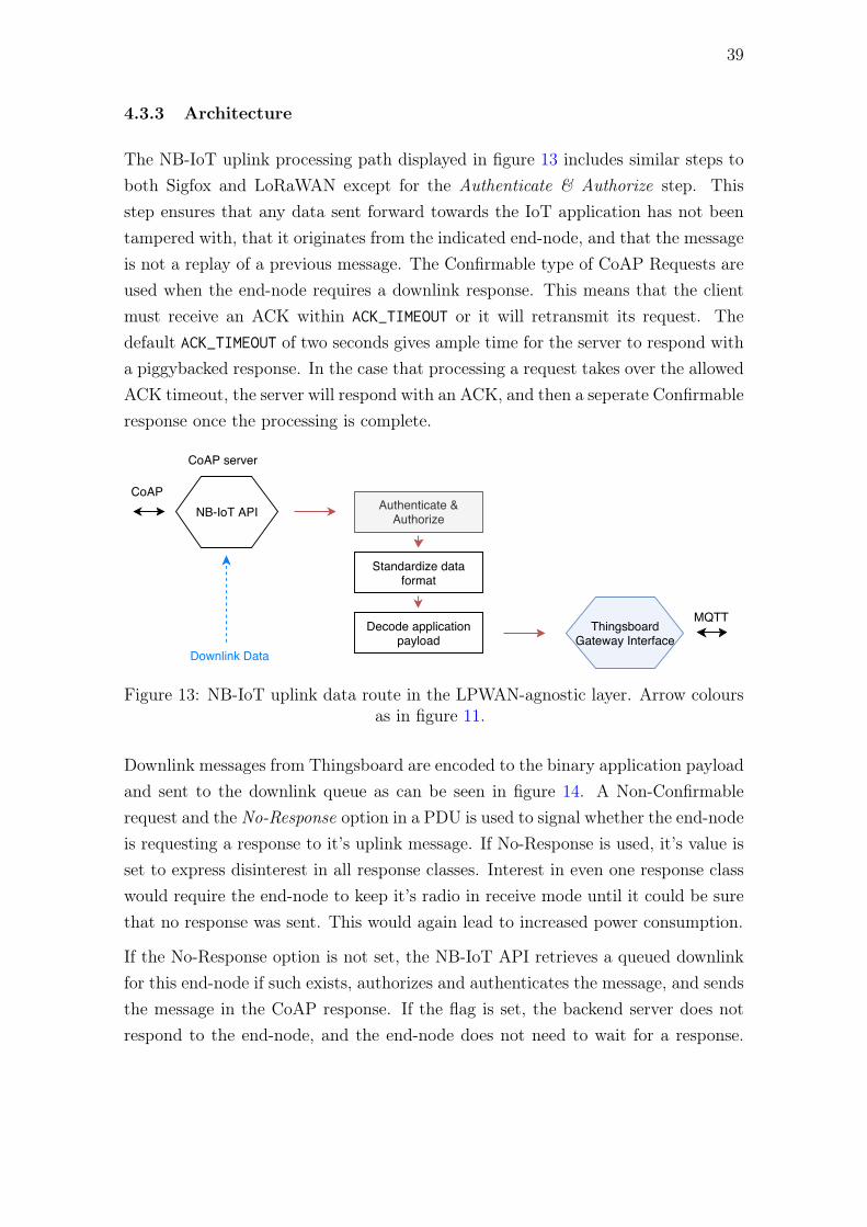
39
4.3.3 Architecture
The NB-IoT uplink processing path displayed in figure 13 includes similar steps toboth Sigfox and LoRaWAN except for the Authenticate & Authorize step. Thisstep ensures that any data sent forward towards the IoT application has not beentampered with, that it originates from the indicated end-node, and that the messageis not a replay of a previous message. The Confirmable type of CoAP Requests areused when the end-node requires a downlink response. This means that the clientmust receive an ACK within ACK_TIMEOUT or it will retransmit its request. Thedefault ACK_TIMEOUT of two seconds gives ample time for the server to respond witha piggybacked response. In the case that processing a request takes over the allowedACK timeout, the server will respond with an ACK, and then a seperate Confirmableresponse once the processing is complete.
ThingsboardGateway Interface
Decode applicationpayload
CoAP NB-IoT API
CoAP server
Authenticate &Authorize
Standardize dataformat
MQTT
Downlink Data
Figure 13: NB-IoT uplink data route in the LPWAN-agnostic layer. Arrow coloursas in figure 11.
Downlink messages from Thingsboard are encoded to the binary application payloadand sent to the downlink queue as can be seen in figure 14. A Non-Confirmablerequest and the No-Response option in a PDU is used to signal whether the end-nodeis requesting a response to it’s uplink message. If No-Response is used, it’s value isset to express disinterest in all response classes. Interest in even one response classwould require the end-node to keep it’s radio in receive mode until it could be surethat no response was sent. This would again lead to increased power consumption.
If the No-Response option is not set, the NB-IoT API retrieves a queued downlinkfor this end-node if such exists, authorizes and authenticates the message, and sendsthe message in the CoAP response. If the flag is set, the backend server does notrespond to the end-node, and the end-node does not need to wait for a response.

40
This reduces end-node battery consumption, as the end-node reduces the time itmust keep the radio receiving.
DownlinkQueue
CoAP NB-IoT API
CoAP server
ThingsboardInterface
MQTT
Authenticate &Authorize
Encode applicationpayload
Uplink Data
Figure 14: NB-IoT downlink data route in the LPWAN-agnostic layer. Arrowcolours as in figure 11.
4.4 Outcome and Future Work
The essential requirements listed in section 3 were met. Uplink transmissions fromall networks are received by Thingsboard without regard for their origin. End-nodenetworks can currently be identified by their names in Thingsboard, as each networkhas a different way of displaying the unique identifiers. Downlink transmissions arepossible in all networks, but rate limiting of downlinks for all networks is not in-cluded in this implementation. All used communication modules may enter theirown low-power modes, and the power consumption of the modules are all under 25µA. The output of the LPWAN-agnostic layer is JSON including the name of thephysical quantity, and the data object form for both up- and downlink messages canbe modified as required. The authentication and authorize requirement is imple-mented in both directions for all networks, with Sigfox and LoRaWAN relying onready-made specifications and implementations and the NB-IoT network using thecustom implementation. The anti-eavesdropping requirement is partially fulfilled.Messages can not be eavesdropped on in any IP networks, and the payload contentsare unencrypted only on the Sigfox network.
The LPWAN-agnostic layer in it’s current state generates value as it enables a
41
streamlined approach for developing end-nodes and their software on any of thethree LPWANs. It enables end-node application developers to use a consistent APIfor most types of sensor nodes, resulting in faster future development cycles. Theintegration of the layer into the Thingsboard application allows thorough manualand automated data analysis regardless of the LPWANs in use.
Future improvements could include transitioning to use of OSCORE for NB-IoT au-thentication and an analysis of further integration of the LPWAN-agnostic layer tothe LoRaWAN server and Sigfox backend. The objective of OSCORE is roughly thesame as of the custom implementation built for this thesis. An benefits OSCORE in-tegration could yield benefits for all parties involved in the development of OSCORE.The Sigfox backend and the LoRaWAN server both offer many more APIs than usedin this thesis, and they may allow adding device provisioning or make more data oncurrent end-node performance available to the IoT application.
42
5 Discussion
The goal of this section is to provide insights gained from the reviewed literatureand the thesis implementation.
5.1 General
Sigfox, LoRaWAN and NB-IoT all aim for multi-year battery lifetimes and multiplekilometres of range, but the technical specifics on how the goals were aimed to beachieved differ greatly. Sigfox and LoRaWAN both utilize the 868 MHz band inEurope, while NB-IoT is operated in the licensed spectrum of Mobile Network Op-erators (MNOs). This may have a large impact once the number of deployed IoTend-nodes truly grows to the levels predicted that some predict. Sigfox and LoR-aWAN, operating in unlicensed bands will suffer decreased performance comparedto today. A common way to get around the duty-cycle limits of the ISM band,used for example in The Things Network, is to deploy more devices. On one hand,this may allow for gateways with smaller ranges, more dense deployments and thusdecreased noise. On the other hand, deploying more devices can further use up bandcapacity if used to enable more data throughput through a LPWAN.
In many instances it would be useful to leak the abstraction of the underlying LP-WAN by allowing knowledge of the LPWAN used to propagate to the applicationserver. Take, for example, sending a multiple kB downlink message to a single end-node. If the server-side business logic had knowledge of which LPWAN was beingused, it could send this type of downlink message when it knows the device wasusing NB-IoT. Purposefully leaking the abstraction does bring about much highercomplexity to the application, and it goes against the concept of abstraction. Ifthe objective is to maximally exploit the capabilities of the more flexible networks,NB-IoT and LoRaWAN, the developed application must be tailored to each of thesenetworks. For developing LPWAN-connected end-nodes which infrequently performan update of sensor data to the application server, fully LPWAN-agnostic data linkssuccessfully provide a key abstraction to facilitate fast deployments in the future.
The NB-IoT and LoRaWAN networks capabilities, especially downlink ones, arelimited to what can be supported by the Sigfox network. On one hand such alimitation effectively caps the possibilities of the LoRaWAN and NB-IoT networks,but on the other hand an application requiring more data throughput should not
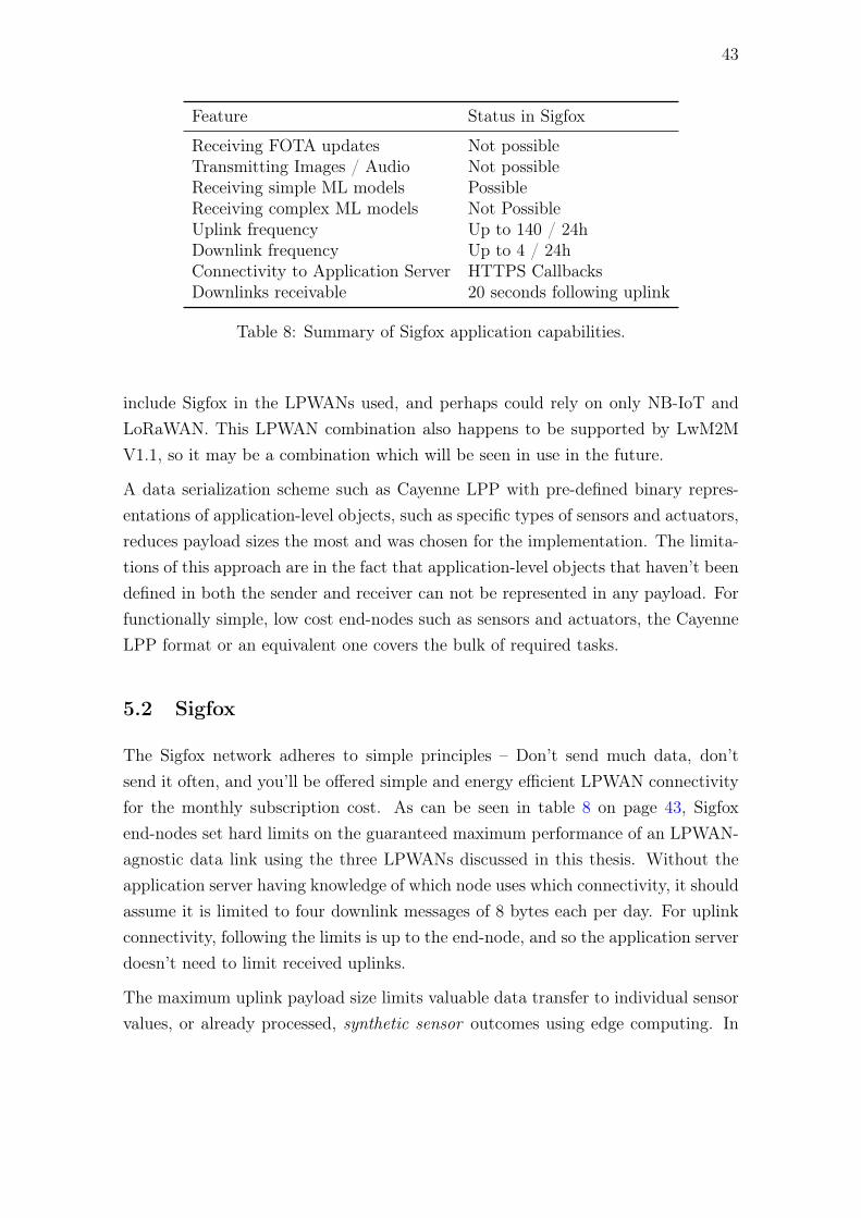
43
Feature Status in Sigfox
Receiving FOTA updates Not possibleTransmitting Images / Audio Not possibleReceiving simple ML models PossibleReceiving complex ML models Not PossibleUplink frequency Up to 140 / 24hDownlink frequency Up to 4 / 24hConnectivity to Application Server HTTPS CallbacksDownlinks receivable 20 seconds following uplink
Table 8: Summary of Sigfox application capabilities.
include Sigfox in the LPWANs used, and perhaps could rely on only NB-IoT andLoRaWAN. This LPWAN combination also happens to be supported by LwM2MV1.1, so it may be a combination which will be seen in use in the future.
A data serialization scheme such as Cayenne LPP with pre-defined binary repres-entations of application-level objects, such as specific types of sensors and actuators,reduces payload sizes the most and was chosen for the implementation. The limita-tions of this approach are in the fact that application-level objects that haven’t beendefined in both the sender and receiver can not be represented in any payload. Forfunctionally simple, low cost end-nodes such as sensors and actuators, the CayenneLPP format or an equivalent one covers the bulk of required tasks.
5.2 Sigfox
The Sigfox network adheres to simple principles – Don’t send much data, don’tsend it often, and you’ll be offered simple and energy efficient LPWAN connectivityfor the monthly subscription cost. As can be seen in table 8 on page 43, Sigfoxend-nodes set hard limits on the guaranteed maximum performance of an LPWAN-agnostic data link using the three LPWANs discussed in this thesis. Without theapplication server having knowledge of which node uses which connectivity, it shouldassume it is limited to four downlink messages of 8 bytes each per day. For uplinkconnectivity, following the limits is up to the end-node, and so the application serverdoesn’t need to limit received uplinks.
The maximum uplink payload size limits valuable data transfer to individual sensorvalues, or already processed, synthetic sensor outcomes using edge computing. In

44
Security Issue Summary
Connectivity abuse Very low potentialData error checking YesData confidentiality On air: No, optionally
On IP network: Yes, HTTPS supportedForging data Not possibleReplaying data Not possible
Table 9: Summary of the security on the Sigfox network.
order to allow for maximal application value generation, any results must be encodedin a compact manner. This is achieved in the implementation by using a formatwith a very heavy schema. Since Sigfox is the only network with unencrypted on-air payloads, this has the benefit of making it less obvious what an end-node ismeasuring or doing.
With the Sigfox backend requiring a downlink response within 20 seconds, the ap-plication server must be able to respond fast, and queue downlink transmissions.
The 12-bit authenticated sequence number used by the Sigfox network providesbasic replay protection. The limits in table 2 allow for 10 days (One tier) or 3days (other tiers) of no reception with only a warning provided once connectivity isrestored. Since the sequence number repeats every 4096 messages, a malicious partywith packet captures of old transmissions could upset connectivity for Sigfox end-nodes. For a Sigfox Platinum subscribed device, transmitting 144 uplinks a day, amessage replay could be achieved in under 29 days of the devices first transmission.Theoretically, transmitting a continuous stream of old packets could completelyblock a legitimate Sigfox end-node from the network. This is because the Sigfoxnetwork should not accept a new packet with the same sequence number as one justreceived.
The Sigfox Networks approach to link security is summarized in table 9 on page44. The Sigfox LPWANs security weaknesses are limited to unencrypted payloadsthat can be eavesdropped on, and a theoretical possibility of an attacker replayingmessages previously sent by the end-node after a full sequence number cycle.

45
Feature Status in LoRaWAN
Receiving FOTA updates PossibleTransmitting Images / Audio Not possibleReceiving simple ML models PossibleReceiving complex ML models PossibleUplink frequency Depends on range, thousands /
24h for close rangesDownlink frequency Depends on amount of end-nodes
per gateway, hundreds / 24h forclose ranges.
Connectivity to Application Server HTTPS Callbacks, MQTT, Web-Sockets [14], [26]
Downlinks receivable Queued, any time [14], [26]
Table 10: LPWAN application features possible with LoRaWAN.
Security Issue Summary
Connectivity abuse Very low potentialData error checking YesData confidentiality On air: Yes
On IP network: Yes, if trusted Network ServerForging data Not possibleReplaying data Not possible, possible in V1.0 [18], [75]
Table 11: Summary of security in the LoRaWAN network.
5.3 LoRaWAN
The open LoRaWAN standard is a flexible protocol which can be tailored to fit amuch larger array of applications than Sigfox. FOTA updates or other large down-link transfers to multiple end-nodes at once are not possible with Sigfox. Neither canmore Sigfox gateways be installed in a specific location to allow more frequent datatransfer to take place. As table 10 presents, these are both possible with LoRaWAN.
In order to be used together with Sigfox as an LPWAN-agnostic data link, somefeatures that LoRaWAN offers must be stripped down to what is offered in Sigfox.End-nodes should communicate to the LPWAN-agnostic data link via LoRaWANClass A, as it features the same functionality, and enables low power end-nodes.Downlink communication must be limited to a maximum application packet size of8 bytes, and can be guaranteed only according to the limit of the Sigfox network.
LoRaWAN has a thorough approach to network security, using two different encryp-

46
tion levels to allow routing without the router knowing the application-level contentsof the packet. The LoRaWAN network is disconnected from the IP network, as theLoRaWAN Network and Application Servers (not the same as an enterprise ap-plication server) only forward messages to and from end-nodes which they know.The standard encrypted communication standards of HTTPS and MQTTS providesimple and secure interfaces to upstream enterprise application servers. The thor-oughly firewalled approach leads to low abuse potential of the end-node in the IPdomain, presented in table 11 on page 45.
LoRaWAN is the only LPWAN examined for which you can build your own privatenetwork. The LoRa gateways with which it can be implemented can be had forunder 200 e. For use-cases in need of good indoor coverage of an area, for examplea factory site, a private LoRaWAN network may be a reasonable investment.
5.4 NB-IoT
Similar to LoRaWAN, NB-IoT provides many ways to utilize the cellular networkto provide low-cost and energy efficient communication. However, for extreme lowenergy use, NB-IoT uses PSM in a similar asynchronous data transfer scheme toSigfox and LoRaWAN. End-nodes that connect to an LPWAN-agnostic server shouldenable PSM in order to maximize battery life.
Assuming the sent data can be fit into Control Plane packets, data should be trans-ported using Control Plane data transfer, which must be configured via an SCEF.This should allow for more efficient communication between the core network andthe end-node, leading to better battery life.
The application possibilities of NB-IoT are listed in table 12. As can be seen, NB-IoT offers the most possibilities for LPWAN usage. Even though it allows for muchlarger transfers, regular large transfers will come at the cost of reduced battery life.The capability to transfer larger payloads should be used for functionality that isnot invoked daily, like firmware updates.
If communicating to the end-node via the SCEF there is no reduction in batterylife for a secure approach. The security model of NB-IoT communication whenconfigured via SCEF is very similar to the ones used by Sigfox and LoRaWAN,as the application server can use standard HTTPS encryption when communicatingwith the core network. A summary of NB-IoT security when operating via the SCEFis presented in table 13. The thesis security objectives would be achieved when using

47
Feature Status in NB-IoT
Receiving FOTA updates PossibleTransmitting Images / Audio PossibleReceiving simple ML models PossibleReceiving complex ML models PossibleUplink frequency Limited only by energy available and
subscriptionDownlink frequency Limited only by energy available and
subscriptionConnectivity to Application Server Direct IP connections from end-node or
IP from Gateway (SCEF Configured)Downlinks receivable Receivable according to adjustable
PSM frequency, Single message queued
Table 12: LPWAN application features possible with NB-IoT.
Security Issue Summary (SCEF) Summary (IP)
Connectivity abuse Low potential Medium potentialData error checking Yes YesData confidentiality Yes YesForging data Not possible Not possibleReplaying data Not possible Not possible
Table 13: Summary of NB-IoT security issues when used via the SCEF and via IP(OSCORE, DTLS or TLS).
a correct implementation of the SCEF for communication with end-nodes.
SCEF support is not, however, available from Finnish mobile network operators asof the end of 2018, so a live SCEF implementation could not be examined in thisstudy. When using NB-IoT without SCEF an end-node is a fully IP-connected nodeand can potentially initiate and receive connections directly from any IP service. Inthis case there is not necessarily any externally configurable firewall, but end-nodesusing the asynchronous uplink mode of connectivity may rely on the fact that theyare only vulnerable for the short duration when they connect to the IP network, andonly connect to pre-determined hosts.
Table 13 on page 47 presents a summary of NB-IoT security when used via IP. SinceNB-IoT end-nodes may be configured to directly contact external IP servers, andmay allow updating of firmware OTA, the security of NB-IoT devices requires amore thorough approach than the other heavily firewalled approaches.
48
A TLS-PSK cipher suite used for DTLS or TLS should result in significant batterylife improvements over most other TLS cipher suites, as the client does not needto download the possibly large server certificate. UDP and thus DTLS should bepreferred over TCP and TLS, as UDP allows for less total back and forth communic-ation. OSCORE seems to be an even better fit for NB-IoT end-nodes with regards toenergy usage. Pre-shared keys can be provisioned in a controlled environment, andfrom then on can provide secure communication between end-node and server. Un-fortunately, there is currently only one open source C implementation of OSCORE,possibly due to it’s current draft status. The implementation is a fork of the Con-tiki OS project with OSCORE support built-in [76], and not a platform-agnosticOSCORE library.
5.5 Implementation
Reception support for measurements aggregated from multiple devices was not re-quired at this stage, but in the future this may be an important way to optimizebattery life without losing time resolution of measurements. Aiming for the pos-sibility of fully described units would be a good goal for making sure that theimplemented system could be interfaced to applications which require explicit units.SenML provides a well-specified way to implement both measurements aggregatedover time and well-specified units.
With the achieved LPWAN-agnostic data connectivity, the application software cancontrol device uplink and downlink frequency to optimize power consumption. ForSigfox and LoRaWAN the uplink period is defined only by when the device wakesup and transmits, but on NB-IoT end-nodes the PSM parameters have to be agreedupon between the end-node and the network. An application that makes use ofPSM period adjustments should define how the end-node reacts if the network doesnot allow the it to use the desired PSM parameters.
The LoRa Server by brocaar supports some additional features compared to lorawan-server used in this implementation, like support for LoRaWAN V1.1, and all deviceclasses defined in LoRaWAN. Due to similar API connectivity options, LoRa Servercould be expected to work well in place of lorawan-server.
A similar approach to the concept studied in this work can be found in lpwan-server [77], which seems to aim to combine data processing from multiple LPWANs.Currently it only has support for LoRaWAN, so it hasn’t yet achieved its goal.
49
The HTTP connector chosen within lorawan-server for interfacing to the LPWAN-agnostic layer has a higher overhead compared to eg. websockets, MQTT or AMQP,which are all supported by lorawan-server. Performance of LoRaWAN communica-tions could be significantly improved by using any of these, with websockets’ possiblybetter suited to the task, as it doesn’t require an external broker running.
If compared to DTLS or OSCORE, the security implementation used for NB-IoT inthe LPWAN-agnostic layer does not provide as much protection. DTLS encrypts thewhole UDP packet, while OSCORE encrypts the full request/response interactionsof the client and server. The custom security implementation focuses primarilyon authenticating the data, and leaves for example the UUID of the end-node,the requested URI path and response code in plain-text. This information is notexpected to be valuable, but still presents a larger risk than what would be expectedin OSCORE or DTLS.

50
6 Conclusions
The main objective of this thesis was to find out if and how battery powered end-nodes from the Sigfox, LoRaWAN and NB-IoT networks could communicate toa common cloud interface. The research sub-questions to be answered were onwhich technical common elements the LPWANs shared, whether the security of thedevices and authenticity of data could be assured, and what limitations utilizing anLPWAN-agnostic approach would suffer from.
An LPWAN-agnostic application layer was found to be both possible and useful,combining communication from Sigfox, LoRaWAN and NB-IoT networks. The mainlimitations found were to do with downlink (to end-node) transmission frequency (4per day) and payload size (8 bytes each).
Security and the Internet Protocols used for the NB-IoT network became a criticalpart of this study, as different implementations’ effects on projected battery life andrequired processor resources were significant.
6.1 Technical similarities
Sigfox and LoRaWAN end-nodes are non-IP devices, and always have gateway soft-ware to translate radio data to IP communication. NB-IoT is the most complexand flexible network out of the three, and utilization of NB-IoT contains an im-portant distinction in whether the NB-IoT network is used via a Service CapabilityExposure Function or not. The SCEF is a component in the cellular core networkwhich provides an externally accessible API to the operators network, and when it isused the NB-IoT network can function the same way as with Sigfox and LoRaWAN.Unfortunately the SCEF is not supported by operators in Finland at the time ofpublication, so end-nodes must directly use IP protocols.
All LPWANs can operate in a common communication mode, using asynchronousuplink transfers (to network) and synchronous downlink transfers (to end-node). Inthis mode of operation, end-nodes keep their radios in a low-power mode until theyhave a message to transmit. Then the end-nodes may transmit the message withoutany measures to establish a connection, and then may listen for an acknowledge-ment of their message, or a data response from the network. In NB-IoT this modeof operation requires the network and the end-node to agree on the utilisation of thePower Saving Mode functionality, and the end-node should act as a client in order

51
to minimize network messaging. For Sigfox, asynchronous uplinks with synchronousdownlinks is the only possible mode of operation, while LoRaWAN and NB-IoT aremore flexible, and can also be set to be constantly listening to their network. Oper-ating based on asynchronous uplink connectivity the most energy efficient operatingmode for all networks as it allows end-nodes to power on their radio only when itwill be of use.
6.2 Security
The security properties against which the different networks were tested were:
• Connectivity can not be abused
• Data errors are checked for
• Data remains confidential on air and on IP systems
• Data authenticity
• No possibility of replay attacks.
The device connectivity in all networks when used as asynchronous-uplink sensornodes can not be harnessed for unwanted activity or other misuse. NB-IoT andLoRaWAN devices have the possibility for Firmware Over The Air (FOTA) updates,but only NB-IoT end-nodes can connect to external IP services after a theoreticalmalicious firmware update. Data errors are checked for in all networks.
The three networks all allow for authentication and authorization of messages sentto and from end-nodes. Sigfox and LoRaWAN end-nodes operate as Non-IP devices,and can only communicate with network gateways. How these gateways are con-figured defines how the communication with a particular end-node is translated tothe IP plane. Communication with end-nodes belonging to different deploymentscan be directed to different IP application servers, making both network functionas if they are behind a very thorough firewall. Only authenticated and author-ized application servers may communicate with specific end-nodes in both networks,significantly reducing risk of attacks against end-nodes. If NB-IoT end-nodes areconfigured to only communicate via the operators SCEF, they also function as non-IP end-nodes. Non-IP NB-IoT end-nodes are authenticated and authorized by thenetwork.
52
When communicating via IP, NB-IoT end-nodes must also authenticate the applica-tion servers and be authenticated by them. How this is implemented has significanteffects on deployment security, battery life and end-node requirements. The fol-lowing only applies to IP end-nodes as clients in a client/server model. TLS andDTLS versions 1.3 and 1.2 fulfill the thesis security requirements energy-efficientlyfor IP traffic (DTLS 1.3 is still in draft status as of the end of 2018) when usedwith Pre-Shared Key (PSK) cipher suites. The most important feature of the PSKcipher suites is to enable reduced data traffic, and thus energy consumption, in theinitial handshake messages. Other possible benefits of the cipher suites are to al-low for use of more resource-efficient symmetric cryptography and more simple keymanagement.
CoAP is an application-layer protocol which is suitable for battery powered NB-IoTdata. When using CoAP, data authentication and confidentiality can be achieved byimplementing OSCORE, an IETF draft for secure CoAP communication. OSCOREis extremely light-weight, encrypts communication with a PSK, and is suitable forend-nodes constrained both in processor resources and energy. OSCORE is a signific-ant improvement over even DTLS 1.3 for these devices, but unfortunately OSCOREis currently lacking C/C++ language implementations.
On-air communication confidentiality is enabled by default in LoRaWAN and NB-IoT, but Sigfox is vulnerable to eavesdropping on messages as it does not encryptthem by default. Sigfox and LoRaWAN on-wire communication can be encryptedby HTTPS with no battery life decrease. NB-IoT communications can be keptconfidential by using OSCORE, DTLS or TLS, in the order of least overhead tomost overhead.
In the Sigfox network, the authenticated sequence number is used to guard againstreplay attacks. The LoRaWAN network is also protected against replay attacks bothin the join procedures, by using a nonce and other data transmission by ignoringrepeated messages. OSCORE, DTLS and TLS all implement sufficient protectionagainst replay attacks.
6.3 Limitations
The concept of completely interchangeable LPWAN data links was found to havesignificant limitations in downlink payload sizes and downlink frequency. End-nodesin the Sigfox network are limited to 8-byte downlink responses and a downlink
53
transmission frequency of 1, 2 or 4 per 24 h, depending on the subscription level.The same limitations must then be applied to all LPWANs in use, as the upstreamapplication server has no way of knowing which network a specific end-node uses.End-nodes are not, however, limited in their uplink payload sizes or frequencies, andmay send as much or as often as their LPWAN API allows.
REFERENCES 54
References
[1] S. M. R. Islam, D. Kwak, M. H. Kabir, M. Hossain and K. Kwak, ‘The inter-net of things for health care: A comprehensive survey’, IEEE Access, vol. 3,pp. 678–708, 2015, issn: 2169-3536. doi: 10.1109/ACCESS.2015.2437951.
[2] M. Centenaro, L. Vangelista, A. Zanella and M. Zorzi, ‘Long-range commu-nications in unlicensed bands: The rising stars in the IoT and smart city scen-arios’, IEEE Wireless Communications, vol. 23, no. 5, pp. 60–67, Oct. 2016,issn: 1536-1284. doi: 10.1109/MWC.2016.7721743.
[3] Y.-P. E. Wang, X. Lin, A. Adhikary, A. Grovlen, Y. Sui, Y. Blankenship,J. Bergman and H. S. Razaghi, ‘A primer on 3GPP narrowband internet ofthings’, IEEE Communications Magazine, vol. 55, no. 3, pp. 117–123, Mar.2017, issn: 0163-6804. doi: 10.1109/MCOM.2017.1600510CM.
[4] J. Bardyn, T. Melly, O. Seller and N. Sornin, ‘IoT: The era of LPWAN is start-ing now’, in ESSCIRC Conference 2016: 42nd European Solid-State CircuitsConference, Sep. 2016, pp. 25–30. doi: 10.1109/ESSCIRC.2016.7598235.
[5] bmeriwether-mydevices, Cayenne Low Power Payload, https://github.com/myDevicesIoT/cayenne-docs/blob/master/docs/LORA.md#cayenne-low-
power-payload, [Online; Accessed commit 37d6154d], 2017.
[6] G. Laput, Y. Zhang and C. Harrison, ‘Synthetic sensors: Towards general-purpose sensing’, in Proceedings of the 2017 CHI Conference on Human Factorsin Computing Systems, ser. CHI ’17, Denver, Colorado, USA: ACM, 2017,pp. 3986–3999, isbn: 978-1-4503-4655-9. doi: 10.1145/3025453.3025773.[Online]. Available: http://doi.acm.org/10.1145/3025453.3025773.
[7] Sigfox S.A. (2018). Sigfox technology overview, [Online]. Available: https://www.sigfox.com/en/sigfox-iot-technology-overview (visited on 2nd Oct.2018).
[8] K. E. Nolan, W. Guibene and M. Y. Kelly, ‘An evaluation of low power widearea network technologies for the internet of things’, in 2016 InternationalWireless Communications and Mobile Computing Conference (IWCMC), Sep.2016, pp. 439–444. doi: 10.1109/IWCMC.2016.7577098.
[9] Sigfox S.A. (2017). Sigfox technical overview, [Online]. Available: https://storage.sbg1.cloud.ovh.net/v1/AUTH_669d7dfced0b44518cb186841d7cbd75/
dev_medias/build_technicalOverview.pdf (visited on 20th Oct. 2018).
REFERENCES 55
[10] ——, (2018). Downlink information, [Online]. Available: https://resources.sigfox.com/document/downlink-information (visited on 25th Oct. 2018).
[11] ——, (2017). Sigfox white paper security, [Online]. Available: https://www.sigfox.com/sites/default/files/1701-SIGFOX-White_Paper_Security.
pdf (visited on 20th Oct. 2018).
[12] ——, (2018). Sequence number: General knowledge, [Online]. Available: https://support.sigfox.com/docs/sequence-number:-general-knowledge (vis-ited on 20th Nov. 2018).
[13] A. Laya, C. Kalalas, F. Vazquez-Gallego, L. Alonso and J. Alonso-Zarate,‘Goodbye, aloha!’, IEEE Access, vol. 4, pp. 2029–2044, 2016, issn: 2169-3536.doi: 10.1109/ACCESS.2016.2557758.
[14] P. Gotthard, Compact server for private LoRaWAN networks, https://github.com/gotthardp/lorawan-server, [Online; Accessed commit 822b3ca3], 2018.
[15] F. Adelantado, X. Vilajosana, P. Tuset-Peiro, B. Martinez, J. Melia-Segui andT. Watteyne, ‘Understanding the limits of lorawan’, IEEE CommunicationsMagazine, vol. 55, no. 9, pp. 34–40, Sep. 2017, issn: 0163-6804. doi: 10.1109/MCOM.2017.1600613.
[16] L. Casals, B. Mir, R. Vidal and C. Gomez, ‘Modeling the energy performance oflorawan’, Sensors (Basel), vol. 17, no. 10, p. 2364, Oct. 2017, PMC5677147[pmcid],issn: 1424-8220. doi: 10.3390/s17102364. [Online]. Available: https://www.ncbi.nlm.nih.gov/pubmed/29035347.
[17] J. Petajajarvi, K. Mikhaylov, A. Roivainen, T. Hanninen and M. Pettissalo,‘On the coverage of lpwans: Range evaluation and channel attenuation modelfor lora technology’, in 2015 14th International Conference on ITS Telecom-munications (ITST), Dec. 2015, pp. 55–59. doi: 10.1109/ITST.2015.7377400.
[18] LoRa Alliance Technical Committee. (2017). LoRaWAN™ 1.1 specification,[Online]. Available: https://lora-alliance.org/sites/default/files/2018-04/lorawantm_specification_-v1.1.pdf (visited on 20th Oct. 2018).
[19] A. Augustin, J. Yi, T. Clausen and W. M. Townsley, ‘A study of LoRa: Longrange & low power networks for the internet of things’, Sensors (Basel), vol. 16,no. 9, p. 1466, Sep. 2016, PMC5038744[pmcid], issn: 1424-8220. doi: 10.3390/s16091466. [Online]. Available: https://www.ncbi.nlm.nih.gov/pubmed/27618064.
REFERENCES 56
[20] J. Stokking. (2017). Firmware updates over low-power wide area networks,[Online]. Available: https://www.thethingsnetwork.org/article/firmware-updates-over-low-power-wide-area-networks (visited on 18th Dec. 2018).
[21] EN 300 220-2 V3.2.1, ‘Short range devices (SRD) operating in the frequencyrange 25 MHz to 1 000 MHz; part 2: Harmonised standard for access to radiospectrum for non specific radio equipment’, European TelecommunicationsStandards Institute, Tech. Rep., 2018.
[22] S. Sakane, LoRa/LoRaWAN time on air calculator, https://github.com/tanupoo/lorawan_toa, [Online; Accessed commit f42009fb], 2018.
[23] SX1272/3/6/7/8: LoRa modem; designers guide, AN1200.13, Rev. 1, SemtechCorporation, Jul. 2013.
[24] LoRa Alliance Technical Committee Regional Parameters Workgroup. (2017).LoRaWAN™ 1.1 regional parameters rev. b, [Online]. Available: https://lora - alliance . org / resource - hub / lorawantm - regional - parameters -
v11rb (visited on 27th Oct. 2018).
[25] F. Delobel, N. E. Rachkidy and A. Guitton, ‘Analysis of the delay of con-firmed downlink frames in Class B of LoRaWAN’, in 85th Vehicular TechnologyConference (VTC), IEEE, Sydney, Australia, Jun. 2017. [Online]. Available:https://hal-clermont-univ.archives-ouvertes.fr/hal-01471673.
[26] O. Brocaar, LoRa Server, https://github.com/brocaar/loraserver, [On-line; Accessed commit b7e724e8], 2018.
[27] D. Flore. (2016). 3GPP standards for the internet-of-things, [Online]. Avail-able: http://www.3gpp.org/images/presentations/3GPP_Standards_for_IoT.pdf (visited on 27th Oct. 2018).
[28] S. Lien, K. Chen and Y. Lin, ‘Toward ubiquitous massive accesses in 3GPPmachine-to-machine communications’, IEEE Communications Magazine, vol. 49,no. 4, pp. 66–74, Apr. 2011, issn: 0163-6804. doi: 10.1109/MCOM.2011.5741148.
[29] GSMA Mobile IoT Initiative participants. (2016). 3GPP low power wide areatechnologies, [Online]. Available: https://www.gsma.com/iot/wp-content/uploads/2016/10/3GPP-Low-Power-Wide-Area-Technologies-GSMA-White-
Paper.pdf (visited on 25th Oct. 2018).
[30] The LTE network architecture; a comprehensive tutorial, CPG0599090904,Alcatel Lucent, 2009.

REFERENCES 57
[31] Definition Networks. (2016). 3GPP SCEF primer, [Online]. Available: http:/ / definitionnetworks . com / products / 3gpp - scef - primer/ (visited on25th Sep. 2018).
[32] Narrowband internet of things whitepaper, 1MA266, Ver. 0e, Rohde & Schwarz,Aug. 2016.
[33] GSM Association. (2018). NB-IoT deployment guide to basic feature set re-quirements, version 2.0, [Online]. Available: https://www.gsma.com/newsroom/wp-content/uploads//CLP.28-v2.0.pdf (visited on 25th Oct. 2018).
[34] TS 33.187 V14.1.0, ‘Security aspects of machine-type communications (MTC)and other mobile data applications communications enhancements (release14)’, 3rd Generation Partnership Project, Tech. Rep., 2018.
[35] E. Rescorla, ‘The Transport Layer Security (TLS) protocol version 1.3’, RFCEditor, RFC 8446, Aug. 2018.
[36] TS 133 401 V15.5.0, ‘LTE; 3GPP system architecture evolution (SAE); secur-ity architecture’, 3rd Generation Partnership Project, Tech. Rep., 2018.
[37] LPWA technology security comparison, Ver. 1.0.1, Franklin Heath Ltd, May2017.
[38] J. Postel, ‘Transmission control protocol’, RFC Editor, STD 7, Sep. 1981.[Online]. Available: http://www.rfc-editor.org/rfc/rfc793.txt.
[39] J. Postel, ‘User datagram protocol’, RFC Editor, STD 6, Aug. 1980, http://www.rfc-editor.org/rfc/rfc768.txt. [Online]. Available: http://www.rfc-editor.org/rfc/rfc768.txt.
[40] E. Rescorla, H. Tschofenig and N. Modadugu, ‘The Datagram Transport LayerSecurity (DTLS) protocol version 1.3’, IETF Secretariat, Internet-Draft draft-ietf-tls-dtls13-28, Jul. 2018. [Online]. Available: http : / / www . ietf . org /
internet-drafts/draft-ietf-tls-dtls13-28.txt.
[41] T. Dierks and E. Rescorla, ‘The transport layer security (tls) protocol version1.2’, RFC Editor, RFC 5246, Aug. 2008. [Online]. Available: http://www.rfc-editor.org/rfc/rfc5246.txt.
[42] E. Rescorla and N. Modadugu, ‘Datagram transport layer security version1.2’, RFC Editor, RFC 6347, Jan. 2012, http://www.rfc- editor.org/rfc/rfc6347.txt. [Online]. Available: http://www.rfc-editor.org/rfc/rfc6347.txt.

REFERENCES 58
[43] P. Miranda, M. Siekkinen and H. Waris, ‘TLS and energy consumption on amobile device: A measurement study’, in 2011 IEEE Symposium on Computersand Communications (ISCC), Jun. 2011, pp. 983–989. doi: 10.1109/ISCC.2011.5983970.
[44] J. Reschke, ‘The ’basic’ HTTP authentication scheme’, RFC Editor, RFC7617, Sep. 2015.
[45] P. Eronen and H. Tschofenig, ‘Pre-shared key ciphersuites for transport layersecurity (tls)’, RFC Editor, RFC 4279, Dec. 2005, http://www.rfc-editor.org/rfc/rfc4279.txt. [Online]. Available: http://www.rfc-editor.org/rfc/rfc4279.txt.
[46] H. Tschofenig and T. Fossati, ‘Transport layer security (tls) / datagram trans-port layer security (dtls) profiles for the internet of things’, RFC Editor, RFC7925, Jul. 2016.
[47] MME administration guide, StarOS release 21.5, Chapter: Power Saving Mode(PSM) in UEs, Cisco Systems, Inc., Jun. 2018.
[48] S. Nyberg, ‘Energy Consumption of Low Power Wide Area Networks’, Master’sthesis, Åbo Akademi, Finland, 2018.
[49] The JSON data interchange syntax, ECMA-404, 2nd ed., ECMA International,Dec. 2017.
[50] T. Bray, ‘Extensible markup language (XML) 1.0 (fifth edition)’, W3C Re-commendation, Nov. 2008. [Online]. Available: https://www.w3.org/TR/2008/REC-xml-20081126/.
[51] C. Bormann and P. Hoffman, ‘Concise binary object representation (cbor)’,RFC Editor, RFC 7049, Oct. 2013.
[52] msgpack,MessagePack specification, https://github.com/msgpack/msgpack/blob/master/spec.md, [Online; Accessed commit 56673202], 2018.
[53] B. Petersen, H. Bindner, S. You and B. Poulsen, ‘Smart grid serializationcomparison: Comparision of serialization for distributed control in the contextof the internet of things’, in 2017 Computing Conference, Jul. 2017, pp. 1339–1346. doi: 10.1109/SAI.2017.8252264.
[54] C. Jennings, Z. Shelby, J. Arkko, A. Keranen and C. Bormann, ‘Sensor meas-urement lists (senml)’, RFC Editor, RFC 8428, Aug. 2018.
[55] IPSO Alliance, IP for smart objects - IPSO objects, https://github.com/IPSO-Alliance/pub, [Online; Accessed commit 34166481], 2018.

REFERENCES 59
[56] E. Ptak. (2018). Cayenne LPP 2.0, [Online]. Available: https://community.mydevices.com/t/cayenne-lpp-2-0/7510 (visited on 20th Nov. 2018).
[57] Z. Shelby, K. Hartke and C. Bormann, ‘The constrained application protocol(coap)’, RFC Editor, RFC 7252, Jun. 2014. [Online]. Available: http://www.rfc-editor.org/rfc/rfc7252.txt.
[58] A. Bhattacharyya, S. Bandyopadhyay, A. Pal and T. Bose, ‘Constrained ap-plication protocol (coap) option for no server response’, RFC Editor, RFC7967, Aug. 2016.
[59] G. Selander, J. Mattsson, F. Palombini and L. Seitz, ‘Object security for con-strained restful environments (oscore)’, IETF Secretariat, Internet-Draft draft-ietf-core-object-security-15, Aug. 2018. [Online]. Available: http://www.ietf.org/internet-drafts/draft-ietf-core-object-security-15.txt.
[60] J. Mattsson and F. Palombini, ‘Comparison of coap security protocols’, IETFSecretariat, Internet-Draft draft-mattsson-lwig-security-protocol-comparison-01, Mar. 2018. [Online]. Available: http://www.ietf.org/internet-drafts/draft-mattsson-lwig-security-protocol-comparison-01.txt.
[61] Docker Inc. (2018). Docker engine, [Online]. Available: https://www.docker.com/products/docker-engine (visited on 15th Nov. 2018).
[62] ——, (2018). Docker security, [Online]. Available: https://docs.docker.com/engine/security/security/ (visited on 15th Nov. 2018).
[63] D. Bernstein, ‘Containers and cloud: From LXC to Docker to Kubernetes’,IEEE Cloud Computing, vol. 1, no. 3, pp. 81–84, Sep. 2014, issn: 2325-6095.doi: 10.1109/MCC.2014.51.
[64] C. Bormann, M. Ersue and A. Keranen, ‘Terminology for constrained-nodenetworks’, RFC Editor, RFC 7228, May 2014. [Online]. Available: http://www.rfc-editor.org/rfc/rfc7228.txt.
[65] Low-power long range LoRa® technology transceiver module, DS50002346C,Rev. C, Microchip Technology Inc., 2017.
[66] WiMOD Lite Gateway data sheet, 4000/40140/0120, Ver. 1.5, IMST GmbH,2017.
[67] Semtech-Cycleo, Lora network packet forwarder project, https://github.com/Lora-net/packet_forwarder, [Online; Accessed commit 7819c438], 2013.
[68] The Things Network. (2018). Documentation, [Online]. Available: https://www.thethingsnetwork.org/docs/ (visited on 18th Dec. 2018).

REFERENCES 60
[69] BG96 AT commands manual, Ver. 2.1, Quectel Wireless Solutions Co., Ltd.,May 2018.
[70] BG96 TCP/IP AT commands manual, Ver. 1.0, Quectel Wireless SolutionsCo., Ltd., Nov. 2017.
[71] BG96 HTTP(S) AT commands manual, Ver. 1.0, Quectel Wireless SolutionsCo., Ltd., Nov. 2017.
[72] Thingsboard Authors, Thingsboard, https : / / github . com / thingsboard /
thingsboard, [Online; Accessed commit 23020a44], 2018.
[73] A. Mills, Cantcoap, https://github.com/staropram/cantcoap, [Online;Accessed commit 8689f29a], 2016.
[74] C. Amsüss, Aiocoap – the python coap library, https://github.com/chrysn/aiocoap, [Online; Accessed commit 28d4f244], 2018.
[75] J. Stokking. (2017). Notes on lorawan security, [Online]. Available: https://medium.com/@brocaar/notes-on-lorawan-security-7e741a8ee4fa (visitedon 27th Oct. 2018).
[76] M. Gunnarsson, Contiki-ng: The next generation contiki, https://github.com/Gunzter/contiki-ng/tree/oscore_12/os/net/app-layer/oscore,[Online; Accessed commit aba72c3c], 2018.
[77] cablelabs, LPWAN server (lpwanserver), https://github.com/cablelabs/lpwanserver, [Online; Accessed commit 0383c036], 2018.
A Sigfox Callback Response Format
{
"device_id" : {
"downlinkData" : "deadbeefcafebabe"
}
}