an organized 3d in vitro model for peripheral nerve studies
TRANSCRIPT
An organized 3D in vitro model for
peripheral nerve studies
Muhammad Fauzi Daud
A thesis submitted for the degree of Doctor of Philosophy
Department of Material Science and Engineering
University of Sheffield

1
Abstract
Three-dimensional cell cultures have been proposed to address the limitations in two-
dimensional cell cultures (i.e. lack of relevant architectural features) and very few have
developed 3D cell culture methods for peripheral nerve studies. Therefore, the present study
reports on the development of a 3D in vitro peripheral nerve model using aligned electrospun
polycaprolactone fibre scaffolds manufactured under tightly controlled and reproducible
conditions with uniform diameters of 1 µm, 5 µm and 8 µm. Fibres were characterized by
SEM for diameter, density and alignment properties and formed in to scaffolds for 3D in vitro
culture. Three different approaches were adopted using: i) neuronal or primary Schwann cell
cultures alone; ii) neuronal and primary Schwann cells in co-culture and iii) isolated dorsal
root ganglion cultures, containing both neuronal and Schwann cells, with
immunohistochemical and 3D confocal microscopy analysis. Neurite guidance was evident
on all fibres diameters with the longest neurites detected on 8 µm fibres when cultured alone.
However, co-culture with primary Schwann cells was found to enable neurite formation on
all scaffolds. Dorsal root ganglion explants when grown on scaffolds showed both organised
aligned neurite guidance and notably the co-localization of Schwann cells with neurites.
Neurite lengths of up to 2.50 mm were routinely observed using 1 µm diameter fibres after 10
days and all cultures demonstrated a migrating Schwann cell „front‟ of up to 2.70 mm (1 µm
diameter fibres). Thus, a direct relationship was found between fibre diameter, neurite
outgrowth and Schwann cell behaviour. Myelin formation was also studied in
neuronal/Schwann cell co-cultures either as neuronal cells plus primary Schwann cells or as
DRG explants, although no myelin expression was detected. This work therefore supports the
use of aligned electrospun PCL microfibres for the development of 3D peripheral nerve
models in vitro, with future value in a number of areas including developmental biology,
disease studies and the design of devices and scaffolds for peripheral nerve repair.
2
Presentations and publications
Oral presentations
12th
Annual White Rose Work in Progress Meeting, Biomaterials and Tissue Engineering
Group, University of Leeds (December 2010)
Development of aligned polycaprolactone microfilaments for peripheral nerve repair
M.F. Daud and J.W. Haycock
13th
Annual White Rose Work in Progress Meeting, Biomaterials and Tissue Engineering
Group, University of Sheffield (December 2011)
Aligned polycaprolactone microfilaments as a scaffold for peripheral nerve repair and the
development of a 3D peripheral nerve model
M.F. Daud, K.C. Pawar and J.W. Haycock
Tissue and Cell Engineering Society Annual Meeting, University of Liverpool (July 2012)
The development of a 3D neuronal glial co-culture model using aligned electrospun
polycaprolactone (PCL) microfiber scaffolds for peripheral nerve studies
M.F. Daud, K.C. Pawar, F. Claeyssens, A.J. Ryan, J.W. Haycock
Abstract published in: European Cells and Materials (2012); 23 (suppl 4): page 6
3rd
TERMIS World Congress, Vienna, Austria (September 2012)
Development of a 3D neuronal glial co-culture model for peripheral nerve studies and repair
strategies
M.F. Daud, K.C. Pawar, F. Claeyssens, A.J. Ryan, J.W. Haycock
Abstract published in: Journal of Tissue Engineering and Regenerative Medicine (2012); 6
(suppl 1): pages: 352-352

3
Poster presentations
Tissue and Cell Engineering Society Annual Meeting, University of Leeds (July 2011)
Directing neuronal cell outgrowth and Schwann cell organisation with aligned
polycaprolactone microfibre scaffolds
M.F. Daud, A.J. Ryan, J.W. Haycock
Abstract published in: European Cells and Materials (2011); 22 (suppl 3): page 17
3rd
TERMIS World Congress, Vienna, Austria (September 2012)
Development of a 3D neuronal glial co-culture model for peripheral nerve studies and repair
strategies
M.F. Daud, K.C. Pawar, F. Claeyssens, A.J. Ryan, J.W. Haycock
Abstract published in: Journal of Tissue Engineering and Regenerative Medicine (2012); 6
(suppl 1): pages: 352-352
Publications
An aligned 3D neuronal-glial co-culture model for peripheral nerve studies
M.F. Daud, K.C. Pawar, F. Claeyssens, A.J. Ryan, J.W. Haycock
Biomaterials, 2012. 33(25): p. 5901-13.

4
Acknowledgements
I would like to express my utmost gratitude to my supervisor, Professor John W
Haycock for guidance and support in the completion of this study.
I would like to acknowledge Dr Kiran Pawar for his contributions in dorsal root
ganglia explants studies, Mr David Bolton and Miss Elen Bray, from CM Technologies for
generously lending the Cell-IQTM
system together with technical assistance for NG108-15
neuronal cell studies and Miss Claire Johnson and Mr Mark Wagner for technical support in
the laboratory. I would also like to thank friends and colleagues at Kroto Research Institute
for assistance and support during the course of the study.
I would like to acknowledge Majlis Amanah Rakyat (MARA), a Malaysian
government agency and the University of Kuala Lumpur for funding my PhD study here at
the University of Sheffield.
Finally, I would like to thank my wife and children as well as my parents and family
in Malaysia for their moral supports and encouragements during my time in the United
Kingdom.

5
Table of Contents
Abstract ..................................................................................................................................... 1
Presentations and publications ............................................................................................... 2
Oral presentations ...................................................................................................................... 2
Poster presentations ................................................................................................................... 3
Publications ................................................................................................................................ 3
Acknowledgements .................................................................................................................. 4
1. Introduction ........................................................................................................................ 10
2. Literature review ............................................................................................................... 12
2.1 Peripheral nervous system ................................................................................................. 12
2.1.1. Cellular composition in the peripheral nervous system ............................................ 12
2.1.2. The organization of peripheral nerve tissue .............................................................. 14
2.1.3. The myelin sheath ..................................................................................................... 16
2.1.4. Injury responses and regeneration in peripheral nerve ............................................. 18
2.1.5. Myelination in the peripheral nerve .......................................................................... 22
2.2. Nerve guidance conduits for peripheral nerve repair ........................................................ 25
2.2.1. Peripheral nerve injury and its current clinical treatments ........................................ 25
2.2.2. Nerve guidance conduits (NGC) ............................................................................... 26
2.2.3. Current ideas on the design of nerve guidance conduits ........................................... 28
2.3. Three dimensional cell culture .......................................................................................... 36
2.3.1. Methods for 3D cell culture ...................................................................................... 38
2.3.2. Three-dimensional culture models for peripheral nerve studies ............................... 39
2.4. Electrospinning ................................................................................................................. 41
2.4.1. Electrospinning: a versatile technique for fibres fabrication .................................... 42
2.5. Polycaprolactone as a biomaterial .................................................................................... 46
2.5.1. The synthesis of polycaprolactone (PCL) ................................................................. 47
6
2.5.2. The biodegradation of PCL ....................................................................................... 48
2.5.3. Biocompatibility ........................................................................................................ 49
3. Aims of the study ................................................................................................................ 50
4. Materials and methods ...................................................................................................... 51
4.1. Fabrication of aligned polycaprolactone microfibres by electrospinning ......................... 51
4.1.1. Electrospinning ......................................................................................................... 51
4.1.2. Optimization of polycaprolactone molecular weight and solution concentration for
electrospinning aligned microfibres .................................................................................... 52
4.1.3. Fabrication of aligned polycaprolactone microfibres with different diameter by
electrospinning .................................................................................................................... 52
4.1.4. Physical characterization of aligned PCL microfibres with different diameters by
scanning electron microscopy (SEM) ................................................................................. 53
4.2. Preparation of aligned PCL microfibres and control flat surfaces for cell and tissue
culture ...................................................................................................................................... 54
4.2.1. Preparation of aligned PCL microfibres for neuronal cell, primary Schwann cell and
dorsal root ganglion (DRG) culture .................................................................................... 54
4.2.2. Preparation of PCL thin films for neuronal and primary Schwann cell culture ........ 54
4.3. Neuronal cell culture on aligned PCL microfibres ........................................................... 55
4.3.1. NG108-15 neuronal cell culture ................................................................................ 55
4.3.2. Investigation on the effect of serum on neuronal cell differentiation and proliferation
study by the Cell-IQTM
live imaging and analysis system. ................................................. 55
4.3.3. NG108-15 neuronal cell culture on aligned PCL microfibres and control flat
surfaces ................................................................................................................................ 56
4.3.4. F-actin labelling with phalloidin-tetramethylrhodamine B isothiocyanate
(phalloidin-TRITC) for visualization of neuronal cells by confocal microscopy ............... 57
4.3.5. Immunolabelling of neuronal cells for a neuronal cell specific marker, β III-tubulin
for visualization by confocal microscopy ........................................................................... 57
4.3.6. Live/dead measurement of neuronal cells ................................................................. 58
4.3.7. Neurite outgrowth assessment .................................................................................. 59
4.3.8. Quantification of the total number of NG108-15 neuronal cell per unit surface area
on aligned PCL microfibres ................................................................................................ 59
4.4. Primary Schwann cells cultured on aligned PCL microfibres .......................................... 60
7
4.4.1. Isolation and culture of primary Schwann cells ........................................................ 60
4.4.2. Primary Schwann cell culture on aligned PCL microfibres and control flat surfaces
............................................................................................................................................. 61
4.4.3. Immunolabelling for S100β Schwann cell marker by confocal microscopy ............ 61
4.4.4. Live/dead measurement of primary Schwann cells for cell viability assessment .... 62
4.4.5. Assessment of primary Schwann cell morphology .................................................. 63
4.4.6. Quantification of the total number of primary Schwann cell per unit surface area on
aligned PCL microfibres ..................................................................................................... 63
4.5. Co-culture of neuronal cells and Schwann cells on aligned PCL microfibres ................. 64
2.5.1. Co-culture of NG108-15 neuronal cells and Schwann cells on aligned PCL
microfibres .......................................................................................................................... 64
4.5.2. Dorsal root ganglion (DRG) explant cultures ........................................................... 64
4.5.3. Dorsal root ganglion (DRG) explants cultured on aligned PCL microfibres with
different diameters. ............................................................................................................. 65
4.5.4. Immunolabelling for S100β and βIII-tubulin for visualization of Schwann cells and
neuronal cells in co-culture by confocal microscopy .......................................................... 65
4.5.5. Neurite outgrowth assessment in NG108-15 neuronal- Schwann cell co-culture .... 66
4.5.6. Axon outgrowth and Schwann cell migration assessment in neuronal-Schwann cell
co-cultures derived from DRGs explants. ........................................................................... 67
4.6. Myelination studies in neuronal-Schwann cell co-culture on aligned PCL microfibres .. 67
4.6.1. Dorsal root ganglion (DRG) culture on aligned PCL microfibres and laminin-coated
tissue culture plate for myelination study ........................................................................... 67
4.6.2. Dorsal root ganglion (DRG) dissociation and culture ............................................... 68
4.6.3. Co-culture of primary neuronal cells and Schwann cells established from dissociated
dorsal root ganglion (DRG) for myelination study ............................................................. 69
4.6.4. Co-culture of primary neuronal cells and Schwann cells established from dissociated
dorsal root ganglion (DRG) on aligned PCL microfibres for myelination study ............... 70
4.6.5. Immunolabelling for myelin basic protein and myelin protein zero for the detection
of myelin expression in dorsal root ganglion (DRG) explants culture and dissociated DRG
culture .................................................................................................................................. 70
4.6.6. Assessment of myelin expression by Sudan Black B staining .................................. 71
4.6.7. Examination of the myelin sheath in rat sciatic nerves by transmission electron
microscopy .......................................................................................................................... 72
4.6.8. Examination of myelination in neuronal-Schwann cell co-cultures on aligned PCL
microfibers by transmission electron microscopy (TEM) .................................................. 73
4.7. Statistical Analysis ............................................................................................................ 74
8
5. Results ................................................................................................................................. 75
5.1. Fabrication of aligned polycaprolactone (PCL) microfibres by electrospinning .............. 75
5.1.1. Optimization of polycaprolactone (PCL) molecular weight and solution
concentration for electrospinning aligned microfibres ....................................................... 75
5.1.2. Fabrication of aligned PCL microfibres with different fibre diameters .................... 79
5.2. NG108-15 neuronal cell culture on aligned PCL microfibres .......................................... 86
5.2.1. The effect of serum on NG108-15 neuronal cell differentiation and proliferation ... 86
5.2.2. Determination of the optimal culture duration for NG108-15 neuronal cell culture on
aligned polycaprolactone (PCL) microfibres ...................................................................... 92
5.2.3. NG108-15 neuronal cells culture on aligned PCL microfibres with different fibre
diameters ............................................................................................................................. 93
5.2.4. The effect of fibre diameter on the extent of NG108-15 neuronal cell differentiation
............................................................................................................................................. 96
5.2.5. NG108-15 neuronal cell viability on aligned PCL microfibres with different fibre
diameters ........................................................................................................................... 101
5.2.6. Quantification of the total number of NG108-15 neuronal cell per unit surface area
on aligned PCL microfibres with different fibre diameters .............................................. 104
5.3. Primary Schwann cell culture on aligned PCL microfibres............................................ 106
5.3.1. Determination of the optimal culture duration for primary Schwann cells on aligned
polycaprolactone (PCL) microfibres ................................................................................. 106
5.3.2. Primary Schwann cell culture on aligned PCL microfibres with different fibre
diameters ........................................................................................................................... 106
5.3.3. The effect of fibre diameter on the phenotype of primary Schwann cells .............. 110
5.3.4. Primary Schwann cell viability on aligned PCL microfibres with different diameters
........................................................................................................................................... 112
5.3.5. Quantification of the total number of primary Schwann cell per unit surface area on
aligned PCL microfibres with different fibre diameters ................................................... 115
5.4. Co-culture of neuronal and Schwann cells on aligned polycaprolactone (PCL)
microfibres ............................................................................................................................. 117
5.4.1. Determination of the optimal seeding number for NG108-15 neuronal cells for
establishing neuronal-Schwann cell co-cultures on aligned polycaprolactone (PCL)
microfibres ........................................................................................................................ 117
5.4.2. NG108-15 neuronal cell/primary Schwann cell co-cultures on aligned PCL
microfibres with different fibre diameters ........................................................................ 119

9
5.4.3. Neuronal-Schwann cell co-cultures derived from dorsal root ganglion (DRG)
explants on aligned PCL microfibres with different fibre diameters. ............................... 122
5.5. Study of Schwann cell myelination on aligned polycaprolactone (PCL) microfibres.... 126
5.5.1. Myelination of neuronal – Schwann cell co-cultures derived from dorsal root
ganglion (DRG) explants. ................................................................................................. 126
5.5.2. Myelination of neuronal – Schwann cell co-cultures derived from dissociated dorsal
root ganglion (DRG). ........................................................................................................ 130
5.5.3. Myelination of neuronal – Schwann cell co-cultures derived from dissociated dorsal
root ganglion (DRG) on aligned PCL microfibres. ........................................................... 134
6. Discussion.......................................................................................................................... 136
6.1 Fabrication of aligned microfibres scaffold by electrospinning for in vitro 3D peripheral
nerve model ............................................................................................................................ 137
6.2 The effect of fibre diameter of aligned PCL microfibre scaffolds on neurite outgrowth 139
6.3 The effect of fibre diameter of aligned PCL microfibres on Schwann cells phenotype .. 141
6.4 Neuronal-Schwann cell interactions on aligned PCL microfibres with different fibre
diameters ................................................................................................................................ 143
6.5 The development of myelin sheath on aligned PCL microfibres .................................... 144
7. Future work ...................................................................................................................... 146
8. Conclusions ....................................................................................................................... 147
9. References ......................................................................................................................... 149

10
1. Introduction
For several years, numerous studies ranging from drug development through to
developmental biology have relied on two-dimensional culture methods of eukaryotic cells
on flat substrates made from glass or polystyrene. Although the method can provide useful
cell or tissue physiological information, monolayer cell culture is an oversimplified model
which fails to accurately represent the microenvironment of the native tissue, in term of
mechanical and biochemical cues, cell-cell and cell-matrix communication and architectural
elements. Obviously, the lack of relevance architectural features is the major disadvantage
which may lead to differing biological responses than in the original tissue since normal cell
behaviour such as receptor expression, cellular proliferation and migration and apoptosis
require spatial cues from the surrounding environment. Many 2D cell culture studies also fail
to address the interactions between different cell types which are present in the native tissue,
hence unable to accurately replicate normal cellular function in vitro. To address these
limitations, a number of studies have attempted to develop methods for three-dimensional
culture models, focusing on the spatial cellular organisation.
Very few studies have described the methods for the development of in vitro 3D
models for peripheral nerve tissue. Nonetheless, these models may have significant
importance in neuropathy, therapeutic studies, developmental neurobiology or nerve
regeneration. Presently, methods for peripheral nerve studies are limited to two-dimensional
cell/tissue cultures and animal models. The 2D culture models commonly involve the use of
cell isolates or tissue explants from peripheral nerve tissue. For examples, dorsal root ganglia,
in dissociated or explant forms, are used to obtain sensory neurons. Motor neurons are
isolated from spinal cord and Schwann cells from sciatic nerve [1-3]. The use of cell lines
such as NG108-15, PC12 and SH-SY5Y are also commonplace as models representing
neuronal and Schwann cells in in vitro studies [4-6]. Peripheral neuropathy and therapeutic

11
studies are usually confined to the use of genetically engineered animal models to simulate
disease conditions [7]. There also has been an increase in the use of animal models for nerve
regeneration studies and the development of devices for peripheral nerve repair.
The development of 3D culture models for peripheral nerve may also have importance
in the improvement of nerve guidance conduits for peripheral nerve reconstruction following
injury. Nerve guidance conduits (NGCs) have been researched extensively for repairing gap
injuries with particular consideration on axons and Schwann cell growth as well as functional
recovery, but are not commonplace in current clinical practice. Six commercially available
devices exist presently, where all are comprised of a simple hollow tube in to which proximal
and distal stumps are inserted (reviewed in [8]). Functional recovery, irrespective of whether
NGCs are made from a synthetic or natural materials is comparable to autografting for small
nerve gaps [9, 10], but typically restricted to a regeneration distance of 20-25 mm [8]. The
inclusion of internal structures such as microchannels [11] or aligned fibres [12] for
improving axonal regrowth (and Schwann cell migration) has been reported by a number of
groups [13, 14], in combination with the delivery of support cells e.g. Schwann cells [15] or
stem cells [6, 16, 17]. It is envisaged that scaffold designs for in vitro peripheral nerve
models may be implemented in clinical use, in which the scaffolds can be used as
intraluminal structures for the improvement of nerve conduit designs.
The designs of scaffolds for such models must not only promote axon and Schwann
cell growth, but must also provide relevant tissue organization and support neuronal-glial
interactions. Therefore, this study describes the development of aligned three-dimensional
culture model for peripheral nerve tissue using aligned electrospun polycaprolactone
microfibres as scaffolds.

12
2. Literature review
2.1 Peripheral nervous system
The nervous system is essentially a communication system in the body which relays
signals in response to the external and internal stimuli in the form of electrical impulse
through an extensive network of nerve cells. The system is responsible to regulate and
coordinate the body and organs functions. Anatomically, the nervous system is divided into
two parts:
1. The central nervous system, which consists of the brain and the spinal cord and
2. The peripheral nervous system, which consists of the nerves and clusters of nerve cell
bodies called ganglia that are located outside of the central nervous system.
Principally, nerve tissue consists of two types of cells, neurons and supporting cells or
glial cells. The neurons are cells that conduct impulses within the nervous system and glial
cells are non-conducting cells which are in intimate proximity of neurons and support the
functions of neurons. In the PNS, glial cells consist of Schwann cells and satellite cells and
conversely, glial cells in the CNS are more diverse which include oligodendrocytes,
astrocytes, microglia and ependymal cells.
2.1.1. Cellular composition in the peripheral nervous system
Structural characteristic of a neuron include the cell body, axon and dendrites. The
cell body is the main part of a neuron that contains the nucleus and the organelles. The cell
body is also characterized by the presence of Nissl bodies which are basically collections of
rough endoplasmic reticulum and free ribosomes. A neuron commonly extends one long
process from the cell body called an axon which transmits electrical impulse away from the
cell body to other neurons or an effector cells or organs. Some neurons also have branches of

13
shorter processes called dendrites which receive signals from other neurons and relay the
electrical impulse to the cell body.
There are two types of neurons that make up the nerve tissue in the PNS, namely
motor neuron and sensory neuron. Motor neurons are classified as multipolar neuron and they
are characterized with multiple dendrite branches on one end which act as the receptor part of
the neuron and a single axon on the other end which acts as the conducting part of the neuron.
Motor neurons transmit efferent signals from the CNS to effector cells or organs such as
skeletal muscles, smooth muscles and glands. On the other hand, sensory neurons are
unipolar with two axonal branches which emanate from the cell body; one axon connects to
the periphery and one to the CNS. Both branches are conducting. Sensory neurons convey
sensory afferent inputs from cells and organs like skin, tendons and joints. The cell bodies of
motor neurons are located in the ventral horn of the gray matter of the spinal cord and extend
their axons out through a ventral root. The cell bodies of sensory neurons cluster in a
structure called the dorsal root ganglion which is found near the spinal cord. As axons from
both sensory and motor neurons leave the spinal cord, their paths merge in a single spinal
nerve and proceed to their destination.
Besides neurons, the PNS also constitutes two types of glial cells, namely Schwann
cells and satellite cells. The satellite cells are the main glial cells found in the DRG. They are
located intimately around the neuron cell bodies, with approximately a 20 nm gap between
the satellite cells and neuron plasma membrance, and form a sheath of single layer cells [18].
A single sensory neuron is commonly ensheathed with several satellite cells and these
neuron-satellite cells clusters are separated by a layer of connective tissue [19]. The
functional role of the satellite cells is not yet fully understood. However, the presence of
neurotransmitter transporters such glutamate and gamma aminobutyric acid (GABA) in the
cells suggests that they have a role in regulating the microenvironment in the extracellular
14
space of dorsal root ganglia [20, 21]. Although the satellite cells ensheath around the neuron
cell bodies, the sheath does not serve as a barrier layer since proteins and macrophages can
penetrate through the layer [22-24]. Additionally, the satellite cells may also have a role in
injury response, inflammation reactions and neuropathic pain [25-27].
Schwann cells are the most extensively studied glial cells in the PNS due to the fact
that they are abundant throughout the PNS, primarily within the nerve trunk. They are closely
apposed to axons and aligned along the length of axons. Schwann cells exist as myelinating
and non-myelinating Schwann cells, although both arise from a common cell lineage.
Myelinating Schwann cells envelop around axons to form a lipid-rich membrane called the
myelin sheath which insulates axons for proper propagation of the action potential. Each
myelinating Schwann cell only envelops one axon. On the other hand, non-myelinating
Schwann cells do not make the myelin sheath but axons are still enclosed by the Schwann
cell cytoplasm. A single non-myelinating Schwann cell can envelop more than one axon to
form a Remak bundle. In general, the myelin sheath is present around axons with a diameter
of more than ~1 µm and this may be due to the fact that the initiation of myelination is
dependent on the axonal diameter through complex axon-Schwann cell interactions [28, 29].
Depending on circumstances, Schwann cells play a multitude of functions in the nerve tissue.
Besides their role to provide the myelin sheath, Schwann cells are also involved in nerve
development, regeneration and inflammatory reactions [30-33].
2.1.2. The organization of peripheral nerve tissue
Classic images showing the organization of peripheral nerve tissue are commonly
depicted in transverse section which distinctly illustrate that peripheral nerve tissue is
organized in cable structure as shown in Figure 1A. Individual axons (myelinated and
unmyelinated) and their accompanying Schwann cells are enveloped in a layer of connective
tissue called the endoneurium to form an endoneurial tube and a group of endoneurial tubes

15
are bundled in another layer of connective tissue, called the perineurium to form a fascicle.
The perineurium is characterized by up to 15 layers of perineurial cells, interspersed with
connective tissue and they are organized circumferentially around individual fascicles [34].
These layers act as a diffusion barrier in controlling the microenvironment within the
endoneurial tube [35] as well as contributing mechanical support together with the perineurial
connective tissue, hence making the perineurium the primary load-bearing structure for the
peripheral nerve [36]. The outermost layer of the peripheral nerve, called the epineurium,
consists of a layer of connective tissue which bundles the fascicles to form a single peripheral
nerve. In a multifascicular nerve, the epineurium may be divided into the interfascicular
epineurium which separates the fascicles and epifascicular epineurium which forms a sheath
surrounding the peripheral nerve.
Figure 1: (A) Transverse organization of a peripheral nerve with ten fascicles which contains
the epineurial epineurium (EP), the epifascicular epineurium (ep), perineurium (pe) and
endoneurium (arrow). (B) Longitudinal arrangement of a peripheral nerve can be in cable
form (1) or plexiform (2). (Modified from JD Stewart [37])

16
Unlike the transverse organization, the longitudinal organization of the peripheral
nerve can be in two forms; 1) cable form or 2) plexiform (Figure 1B). The cable form of the
peripheral nerve exhibits discrete fascicles without axons interchanging between individual
fascicles. The plexiform of the peripheral nerve is characterized by the presence of the axons
interchanging and the axonal path re-routeing to and from separate fascicles [37]. Proximally,
the fascicles of the peripheral nerve are arranged in a plexiform but the nerve is organized in
a cable form towards the distal portion [38]. This means that a partial lesion or partial
stimulation on a nerve proximally may affect a group of muscles whereas distally, the
affected muscles may be more limited and specific [39-41].
2.1.3. The myelin sheath
The conduction of electrical impulses takes place in axons through the propagation of
an action potential which is triggered by the depolarization of the axonal electrical membrane
potential. Axonal membranes depolarize due to the elevation of intracellular positively
charged sodium ions. The depolarization activates the voltage-gated sodium channels,
inducing the influx of more sodium ions and this triggers the depolarization of the adjacent
membrane. The process continues along axons, hence propagating the action potential. In
myelinated axons, the depolarization jumps from one node of Ranvier to the next one because
the myelin sheath prevents the continuous sequential depolarization, hence the term saltatory
conduction. This conduction mechanism allows for rapid action potential propagation while
conserving space and energy [42], thus making the myelin sheath one of the important
features in the nervous system. A compromise in the integrity of the myelin sheath is known
to cause a number of devastating neuropathies such as the Guillain-Barre syndrome, Charcot-
Marie-Tooth disease and multiple sclerosis.

17
Figure 2: (A) Ultrastructure of myelin sheath in transverse section. White arrow indicates the
major dense line and black arrow indicates the intraperiod line. (B) Longitudinal organization
of myelin sheath. (Modified from R.H. Quarles et al.. and B Garbay et al.. [43, 44])
In the PNS, Schwann cells form the myelin sheath by extending their plasma
membrane around axons multiple times to create a lamellae structure surrounding the axonal
surface. The sheath is composed of highly compacted layers of membrane with a series of
alternating layers of the apposed cytoplasmic surfaces (form the major dense line) and the
apposed extracellular surfaces (form the intraperiod line) of Schwann cell membranes (Figure
2A). The region within the cytoplasm that is void of compaction creates Schmidt-Lantermann
clefts which continue spirally through the sheath (Figure 2B). The sheath contains a high
proportion of lipid (70-80% of the dry mass) which is essential in providing the electrically
insulating property. The protein components account for 20-30% of the dry mass which
comprise of glycoproteins (myelin protein zero (P0), peripheral myelin protein 22 (PMP 22),
periaxin and myelin-associated glycoprotein (MAG)), basic proteins (myelin basic protein
(MBP) and protein P2) and diverse types of proteins (2‟,3‟- cyclic nucleotide 3‟-
phosphodiesterase, proteolipid proteins (PLP/DM20)).

18
Myelin protein zero (P0) is the most abundant protein which represents 50-70% of the
total proteins in the myelin sheath [45-47]. P0 is a 28 kDa integral membrane protein with
219 amino acid residues and it has a glycans-containing extracellular domain (residues 1-
124), a hydrophobic transmembrane domain (residues 125-150) and a cytoplasmic domain
(residues 151-219). The extracellular domain of P0 protein interacts with other P0 proteins on
the apposing membrane through homophilic interaction to form tetramers which hold the
apposing membrane together to form the intraperiod line [48, 49]. The second largest protein
component in the myelin sheath is the myelin basic proteins (MBP) which accounts for
approximately 25% of the dry mass. The MBP are peripheral membrane proteins that can
exist in the PNS as 21.5, 18.5, 17, and 14 kDa proteins [44]. The proteins interact with the
cytoplasmic domain of P0 protein to form the major dense line, hence providing the
compaction of the myelin structure [50, 51]. The relative abundance of P0 and MBP reflects
their significant role in the formation and maintenance of the myelin structure. Collectively,
other myelin proteins make up less than 20% of the total protein contain in the myelin sheath
(reviewed in B. Garby et al.. 2000 [44]).
2.1.4. Injury responses and regeneration in peripheral nerve
It has long been recognized that the peripheral nerve has a better regenerating
capability than the central nerve and this is mainly attributed to the permissive environment
within the peripheral nerve system rather than the intrinsic factors of the neurons [52, 53].
The processes that take place in the peripheral nerve in response to injury are complex,
involving both neurons, Schwann cells as well as other non-neuronal cells through intricate
interactions of trophic factors and the extracellular matrix. The injury response comprises of
the degeneration of axonal and myelin components, the remodelling of the
microenvironment, and axon regeneration and maturation.

19
Axotomy triggers a degenerative process, termed as Wallerian degeneration. The
process is initiated by the influx of intracellular calcium ion (Ca2+
), which activates calpains,
a type of proteases essential for the degradation of microtubules and neurofilaments [54, 55].
Consequently, the axonal membrane and cytoskeleton collapse and disintegrate and these
events can take place within 48 hours after injury [56]. Due to the lost of the axonal contact
following the axonal fragmentation, Schwann cells start to disintegrate the myelin sheath into
small fragments. Debris produced by the degrading axon and myelin are initially removed by
Schwann cells by phagocytosis but later, macrophages take over the role once macrophage
invasion at the injury site is at a peak [57, 58]. The removal of the debris especially the
myelin debris is crucial for the subsequent axonal regeneration because myelin is very
inhibitory to regeneration [59, 60]. Myelin-associated glycoprotein (MAG), a component of
myelin proteins, has been identified as a possible regeneration inhibitor [61].
Axotomy triggers a series of morphological and molecular changes which take place
both in the proximal and the distal portion of injured nerve. Proximal to the injury site,
changes can be observed as far as at the cell body of neurons. The cell body undergoes a
process called chromatolysis which is characterized by the cell body swelling, the loss of
Nissl bodies, nucleolar enlargement and the displacement of the nucleus to the periphery. The
pattern of gene expression also changes indicating the transition of cellular mode from
“transmitting” to “regenerating”. For instance, neurofilaments subunits and neuropeptides are
downregulated while regeneration-associated genes (RAGs), tubulin and actin proteins are
upregulated [62]. Downregulation of neurofilament proteins is correlated to an increase in the
axoplasm fluidity which facilitates axonal transport [63]. The pattern of neuropeptide
expression also changes following axotomy; calcitonin gene-related peptide (CGRP) is
upregulated while choline acetyltransferase (CAT) is downregulated in axotomized
motoneurons [64].
20
Proximal stumps of transected neurons swell forming axonal endbulbs due to the
accumulation of axoplasmic material and molecules [65]. New axon sprouts arise from the
original axons at the first node of Ranvier from injury site. An axon can give rise to several
axon sprouts which in theory could maximize the chance for reconnection with the target
[66]. However, only sprouts that receive sufficient stimulation from the target organs remain
viable. Axon growth is driven by the growth cones, dynamic specialized structures at the ends
of regenerating axons, through cytoskeletal structure remodelling which results in axon
elongation. Initially, The formation of growth cone occurs using locally available materials in
the axons and is independent from the cell body [67]. The growth cones also actively sense
and respond to specific molecular cues in the ECM through protein receptors causing the
growth cones to advance, pause, turn and retract, which in turn guide axon growth. One of the
receptor types are the integrins and they bind to a number of the extracellular matrix (ECM)
proteins such as laminins and fibronectin (reviewed in [68]). The upregulation of a number of
integrins following injury in peripheral nerve suggests an important role during the
regeneration process [69, 70].
In the distal nerve stump, the degeneration proceeds anterogradely from the injury
site, leaving vacant yet intact endoneurial tubes for Schwann cells proliferation in preparation
to receive the regenerating axons. Within 2 or 3 days after injury, Schwann cells start
proliferating vigorously and occupying along the vacant endoneurial tubes to form the bands
of Büngner which guide the regenerating axons to their target [71]. The stimulation of
Schwann cell proliferation during injury response has been linked to the mitogens released by
the invading macrophages [72, 73] as well as the degraded axolemma fragments [74]. A
second stage of Schwann cell proliferation takes place when regenerating axons reach the
distal stumps, leading to an increment of Schwann cell number by more than threefold [75].

21
Neurotrophic factors and the extracellular matrix facilitate and regulate the
microenvironment within the PNS during nerve regeneration. The neurotrophin family
constitutes of nerve growth factor (NGF), brain derived neurotrophic factor (BDNF),
neurotrophin-3 (NT-3) and neurotrophin 4/5 (NT-4/5). These proteins bind to two types of
transmembrane receptor, tyrosine kinase (trk) receptors family and the p75 receptor through
receptor dimerization, and lead to the stimulation of several intracellular signalling pathways.
Neurotrophin binding may occur through the interaction of trk and p75 receptors which
enhance binding affinity and specificity or directly with trk or p75 receptors independently
(reviewed in [76]). Each neurotrophin has specificity to different trk receptors in which NGF
binds specifically to trk A receptor, BDNF and NT-4/5 to trk B and NT-3 to trk C, however,
all neurotrophins bind to p75 receptor. The neurotrophins are released by the target organs,
internalized at the nerve terminals following binding to the receptors and delivered to the cell
bodies by retrograde axonal transport (reviewed in [77]). Following axotomy, the target
organs and Schwann cells, especially within the distal nerve stumps markedly upregulate the
production of all the neurotrophins except NT-3 [78]. The neurotrophins play an important
role as a survival signal for axotomized neurons. NGF promotes the survival of sensory
neurons [79, 80] while BDNF, NT-3 and NT-4/5, have been shown to promote the survival of
motorneurons [81]. Besides that, the neurotrophins are also involved in promoting nerve
regeneration. For instance, NGF has been shown to promote Schwann cell migration [82],
axon-Schwann cell adhesion [83, 84] and axonal branching [85]. Furthermore, the
neurotrophins also play essential roles in regulating the myelination process (reviewed in
[86]).
Another aspect that contributes to a permissive microenvironment for nerve
regeneration, besides soluble factors release, is the extracellular matrix (ECM) which is
formed as an interstitial matrix or basement membrane. The ECM is composed of a complex
22
network of glycoproteins and proteoglycans including laminin, fibronectin, collagen, and
heparan sulphate. The matrix provides structural supports as well as biochemical cues to cells
through direct interactions with the ECM proteins or by sequestering soluble cues within the
matrix [87]. Laminins and fibronectins have been shown to have stimulatory effects on
axonal outgrowth [88, 89] and Schwann cell proliferation and migration [90]. Furthermore,
following injury, the expression of lamimin and fibronectin within peripheral nerves are
rapidly upregulated, creating a permissive environment for nerve regeneration [91, 92].
Axons also are dependent on the ECM for guiding their growth to correct pathways through
cues provided by collagen and immobilized netrin [87, 93]. Schwann cells also require the
presence of laminins to undergo myelination [94].
2.1.5. Myelination in the peripheral nerve
Physical contact between axons and Schwann cells is a pre-requisite for the formation
of the myelin sheath by Schwann cells since axonal signals for myelination are mediated by
membrane-bound proteins, neuregulin 1 type III (NRG1-III) and nectin-like protein-1 (Necl-
1). NRG1-III is a key regulator for PNS myelination which control the initiation and extent of
myelination by binding to Schwann cell membrane-bound Erb B receptors, resulting to the
activation of PI3K (phosphatidylinositol 3-kinase)/PIP3 [phosphatidylinositol (3,4,5)-
trisphosphate]/AKT (v-Akt murine thymoma viral oncogene homolog) signaling pathway
[95]. Schwann cells require a threshold level of expression of NRG1-III from axons to
differentiate into myelinating cells [95]. This regulatory mechanism may explain why
Schwann cells associated with a large diameter axon form the myelin sheath and vice versa.
Moreover, the thickness of the myelin sheath is also influenced by the amount of axonal
NRG1-III [96].
Cell adhesion molecules, such as the nectin-like family (Necl) of proteins also play an
important role in PNS myelination especially for axon-Schwann cell binding and mediating
23
the cytoskeleton rearrangements during Schwann cell envelopment. Axon-Schwann cell
attachment by the Necl proteins occurs through the interactions of Necl-1, expressed in the
axonal membrane and Necl-4, expressed in the Schwann cell membrane [97, 98].
Nonetheless, the role of Nec1 as the binding partner for Necl-4 may not be as exclusive as
reported in a previous in vivo study and the effect could be potentially compensated by other
proteins in the Necl family [99]. The stimulatory effect of Necl-4 binding on myelination is
modulated by submembranous cytoskeletal proteins, called spectrins by stabilizing the
membrane proteins at the axon-Schwann cell junction and reorganizing the actin cytoskeleton
[100]. Although the interaction between Necl-4 and the spectrins remain unclear, it has been
proposed that protein 4.1G, a cytoskeletal adapter protein, may link the two proteins[100]
since both spectrins and Necl proteins can form complexes with protein 4.1G [101, 102].
Schwann cell polarization takes place during the initial event of myelination,
preceding axonal envelopment by Schwann cells and the process involves asymmetrical
distribution of molecular components as well as morphological polarization. Myelinating
Schwann cells are not only polarized in a radial direction from the ECM to the axons but also
in a longitudinal direction, which is responsible for the organization of different domains in
the myelin sheath i.e. the nodes of Ranvier and the internodes. The regulatory mechanisms of
the polarization of myelinating Schwann cells are not completely understood, though the
spatial cues from the axons and the ECM through specific receptors may play important parts
in the process [103, 104]. Intracellularly, polarity proteins have been shown to localize
distinctly in myelinating cells. For instance, Par3 is asymmetrically concentrated at the axon-
Schwann cell junction upon axonal signals [105]. Other proteins associated with cell polarity
such as Dlg1 and Pals1 are also distributed preferentially at specific regions in the Schwann
cell membrane during myelination [106, 107]. Besides that, membrane bound proteins are
also polarized during myelination. For instance, myelin-associated glycoprotein (MAG) is
24
localized at axon-Schwann cell interface and the noncompacted, spiralling myelin membrane
[108], while TAG-1 and gliomedin at the region near the future location of the node of
Ranvier [109, 110]. Laminin receptor integrin α6-β4 is also found to distinctly localize at the
abaxonal surface of myelinating Schwann cells [103].
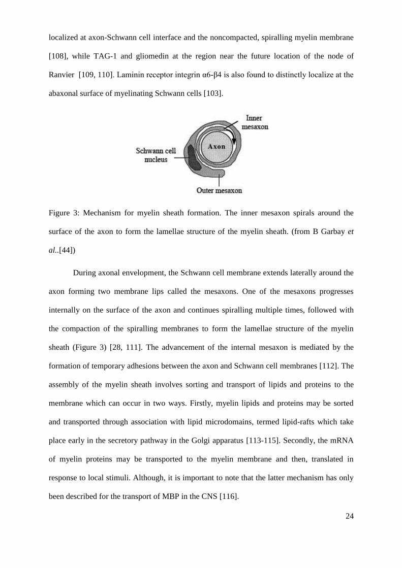
Figure 3: Mechanism for myelin sheath formation. The inner mesaxon spirals around the
surface of the axon to form the lamellae structure of the myelin sheath. (from B Garbay et
al..[44])
During axonal envelopment, the Schwann cell membrane extends laterally around the
axon forming two membrane lips called the mesaxons. One of the mesaxons progresses
internally on the surface of the axon and continues spiralling multiple times, followed with
the compaction of the spiralling membranes to form the lamellae structure of the myelin
sheath (Figure 3) [28, 111]. The advancement of the internal mesaxon is mediated by the
formation of temporary adhesions between the axon and Schwann cell membranes [112]. The
assembly of the myelin sheath involves sorting and transport of lipids and proteins to the
membrane which can occur in two ways. Firstly, myelin lipids and proteins may be sorted
and transported through association with lipid microdomains, termed lipid-rafts which take
place early in the secretory pathway in the Golgi apparatus [113-115]. Secondly, the mRNA
of myelin proteins may be transported to the myelin membrane and then, translated in
response to local stimuli. Although, it is important to note that the latter mechanism has only
been described for the transport of MBP in the CNS [116].
25
2.2. Nerve guidance conduits for peripheral nerve repair
2.2.1. Peripheral nerve injury and its current clinical treatments
Peripheral nerve injuries are commonly caused by acute trauma as a result of road
traffic or industrial accidents. Trauma patients suffer from peripheral nerve injuries may
acquire life-long disability, which may greatly affect the quality of life [117]. The recovery of
peripheral nerve injury depends on the extent of injury. Sunderland‟s classification system
categorizes peripheral nerve injury into five classes according to the degree of severity [38].
A first degree injury is described when nerve continuity is retained with transient functional
loss. Injuries with the interruption of the axons and the myelin sheath but with intact
surrounding connective tissue are classified as second degree injuries. A third degree nerve
injury involves the disruption of the axons with partial injury to the endoneurium. In a fourth
degree injury, all parts of the nerve are disrupted except the epineurium while in a fifth
degree injury, the nerve is completed severed.
Two most established microsurgical methods for repairing peripheral nerve include
end-to-end coaptation and autologous nerve graft transplantation. End-to-end coaptation,
however, is limited for repairing nerve injuries with gaps smaller than 5 mm to avoid
introducing tension across an injury site, which can be adverse to nerve regeneration. For gap
injuries greater than 5 mm, autologous nerve graft transplantation is considered as the “gold
standard”, with superior results in nerve regeneration [118]. In the method, donor nerves are
obtained from functionally less important nerves such as sural nerves, superficial cutaneous
nerves or lateral and medial antebrachii cutaneous nerves [119]. Autograft transplantation,
however, is associated with several key limitations including donor site morbidity and loss of
function, donor material scarcity, potential painful neuroma formation and the requirement of
two surgeries for harvesting graft tissue and repairing damaged nerve [120].

26
Alternatively, nerve allograft transplantation is possible to repair nerve injuries with
comparable results to autografts [121]. Nerve allografts can be obtained from cadaveric or
donor nerve tissues. However, the need for systemic immunosuppressants and rejection risk
make the technique less favourable. Other microsurgical techniques that have been proposed
for repairing peripheral nerve injuries include nerve transfer and end-to-side coaptation [122].
Nerve transfers involve using nerves with redundant functions to reconnect to a damaged
nerve with more crucial functions however, this can lead to loss of functions at donor sites.
End-to-side coaptation is done by suturing the injured distal stump to the side of an injured
donor nerve. The technique is used when the proximal stump of an injured nerve is
unavailable or inaccessible. The technique requires donor nerve axotomy which lead to
collateral axonal sprouting from the donor nerve into the recipient stump. However, both
techniques have not been used widely in clinical settings.
2.2.2. Nerve guidance conduits (NGC)
The use of tubular conduits for repairing peripheral nerve injury as an alternative for
nerve autograft is not a novel idea and its history dates from the 1800‟s in which researchers
experimented with naturally available materials such as bone tube for peripheral nerve repair
[123]. Although current nerve guidance conduits are generated by modern fabrication
techniques rather than using naturally-available tissue, the principle design remains the same
over the years i.e. a tube with hollow lumen. Presently, there are several NGCs which are
approved for clinical use and both naturally-derived and synthetic conduits are commercially
available [120].
Synthetic NGCs include Neurotube® and Neurolac
® which are made from poly-
glycolic acid (PGA) and poly-DL-lactide-co-ɛ-caprolactone (PDLLA/CL), respectively.
Naturally-derived NGCs include NeuraGen and NeuraMatrix/Neuroflex which are type I
collagen-based conduits. Clinical trials revealed that both Neurotube® and Neurolac
®

27
produced good outcomes in nerve defects up to 20 mm [10, 124], however, Neurotube®
degrades faster than Neurolac® (3 months versus 16 months) [120]. Similarly, type I collagen
NeuroGen® has been reported in clinical trials to give good results in nerve defects up to 20
mm and it degrades after 48 months [125]. No clinical studies have yet been conducted on
NeuroMatrix/Neuroflex™ since receiving approval in 2001 [120]. Other types of
commercially available nerve guides that are approved by Food and Drug Administration
(FDA) include non-resorbable nerve guide (Salubridge / Salutunnel™) and decellularized
nerve (Avance®). No report on clinical trials for Salubridge / Salutunnel™ has been
published since the devices were approved for clinical use [120].
NGCs provide mechanical support for reconnecting the injured nerve stumps whilst
guiding axonal extension to the distal nerve stump. By enclosing the injury sites, fibrous
tissue ingrowth is minimized, hence reducing neuroma and scar formation. Moreover, plasma
exudates containing neurotrophic factors and extracellular matrix precursor molecules
(fibrinogen and factor XIII), released by both nerve stumps, are retained within the lumen of
NGCs [126, 127]. The containment of the exudates leads to the formation of a fibrin matrix
inside the lumen of NGCs which develops within the 1 week of NGC implantation [126].
These transient fibrin fibres facilitate the migration of the cellular components (mainly
Schwann cells) into the nerve gap area from both nerve stumps, allowing Schwann cells to
proliferate and form bands of Büngner [128]. The bands provide a platform onto which
axonal extension can progress to the distal nerve stump.
Whilst commercial nerve guides were shown as promising alternatives to autografts,
the regenerative capacity is limited to nerve injuries with 20-25 mm gaps [8]. The nerve
guide design challenge now is to facilitate regeneration for larger gap nerve injuries. The
failure of hollow nerve guide to provide sufficient regeneration across larger gap may be
attributed to the inadequacy of the fibrin matrix formation and insufficient neurotrophic
28
factors and Schwann cells invasion [128]. In facing this challenge, researchers have focused
on new materials, surface coatings, internal scaffolds and the inclusion of growth factors and
support cells to improve nerve guide designs.
2.2.3. Current ideas on the design of nerve guidance conduits
Materials
The ideal material characteristics for a NGC include biocompatibility,
biodegradability, mechanical relevance and permissive properties for nerve regeneration.
Numerous biomaterials have been studied ranging from naturally-derived materials to
synthetic materials. Cell binding domains in natural materials can be advantageous in
promoting neuronal and glial attachment and migration [129] but they may pose a minor risk
of disease transmission and can be relatively costly [130]. Synthetic materials offer more
flexibility in physical and chemical properties, allowing controllability over mechanical and
degradation characteristics and the introduction of microstructure. Though, these materials
are often less biocompatible than natural materials.
1. Naturally–derived materials
Acellular nerve allograft is advantageous due to the relevance of microstructure
provided by the extracellular matrix retained after a decellularization procedure. Avance® is
the only commercial acellular nerve allograft available in the market at present. A clinical
trial conducted on 7 patients to treat nerve gaps of 0.5 – 3 cm in sensory nerves using
Avance® indicated that positive functional recovery was achieved after 9 months [131]. Of
note was that no evidence of infection or rejection was observed in the study. As mentioned
earlier, there are several collagen-based devices that are currently available in commercial
market and NeuroGen® is the most extensively studied nerve guidance conduit in clinical
settings, showing great potential in supporting nerve regeneration. Taras et al.. observed a

29
low level of rejection and scarring after repairing peripheral nerves using NeuroGen® [132].
A clinical study utilizing NeuroGen®
on 14 patients with an average of 12.7 mm gap injury in
digital nerves showed very good results after 12 months with 5 patients achieving good
sensitivity, 1 patient poor and 2 patients with no sensitivity [133]. Of note was that one
patient presented with persisting mild hyperesthesia and three patients with temporary foreign
body sensation.
Other natural materials that have been proposed for nerve guidance conduits include
fibrin, silk fibroin and chitosan. To date, most of the devices are still experimental at pre-
clinical stages although experimental data suggest that the use of the mentioned materials in
nerve guides is promising. For instance, conduits made from fibrin have been shown to
support axonal regeneration, myelination and muscular recovery across 10 mm nerve gap in
rats [134]. A recent study carried out by Park et al. using electrospun silk fibroin conduits for
10 mm sciatic nerve defect in rats revealed that motor function recovery was comparable to
autograft when evaluated by the ankle stance angle (ASA) test [135]. A study by Ghazvani et
al. also suggests that the extent of inflammatory reaction elicited by silk fibroin was
equivalent to collagen conduits [136]. Other studies, using chitosan conduits with
polyglycolic acid (PGA) filaments or bone marrow stromal-derived Schwann cells, produced
positive outcomes, with some degree of functional and physical recovery [137, 138].
2. Synthetic materials
There are two types of synthetic nerve guidance conduits that are currently being
studied or are available commercially; non-resorbable and resorbable devices. Salubridge® /
SaluTunnel® are the sole non-resorbable nerve guidance conduits which have received
approval by the FDA. The devices are composed of hydrophilic polyvinyl alcohol hydrogel
which has a similar water-content property to human tissue [120]. The performance of the
devices remains unknown since there are no publications reporting on pre-clinical and
30
clinical studies for the devices. Other hydrogel conduits include poly(2-hydroxyethyl
methacrylate-co-methyl methacrylate) (PHEMA-MMA) conduits which have been reported
to produce comparable outcomes to autograft in a 10 mm rat sciatic nerve defect [139]. A
long term in vivo study showed that almost 30% of implanted PHEMA-MMA conduits
collapsed and some showed signs of chronic inflammation and calcification [140]. A
comparative study between plain, corrugated and coil-reinforced conduits of PHEMA-MMA
and autografts revealed that coil-reinforced conduits produced equivalent results as autograft
as indicated by the analyses of the nerve action potential and muscle action velocity and the
axon density measurement on a 10 mm rat sciatic model after 16 weeks [141].
Resorbable synthetic nerve guidance conduits are mainly composed of polyesters such
as polyglycolic acid (PGA), poly(lactic-co-glycolic acid) (PLGA), poly-ɛ-caprolactone (PCL)
and poly(DL-lactide-co-caprolactone). Most of the materials have been approved by the
FDA for various biomedical applications. A clinical study involving 98 patients compared the
use of PGA conduits (Neurotube®) versus autografts or direct coaptation to reconstruct digital
nerves [10]. Sensory recovery for nerve reconstruction with PGA conduits were scored as
being 44% excellent, 30% good and 26% poor, compared with 43% excellent, 43% good and
14% poor for the coaptation/autografts. Evaluation of motor functional recovery by PGA
conduits conducted by Rosson et al.. reported some degree of success in recovering motor as
well as sensory functions [142]. The study was carried out on 6 patients having received
Neurotube® to repair short gap nerve injuries and evaluated functional recovery by a
retrospective chart review over a 7-year period.
Other polyesters that have gained considerable attention include polycaprolactone
(PCL) and polyhydroxybutyrate (PHB) and both possess attractive qualities as biomaterials
for regenerative medicine [143, 144]. PCL conduits in combination with nerve growth factor
(NGF) and tirofiban supported nerve regeneration across a 10 mm gap in rat sciatic nerve as

31
well as promoting re-innervation of gastrocnemius muscle after 8 weeks [145]. Of note was
the superior performance of NGF/tirofiban conjugated PCL conduits compared to NGF only
and plain PCL conduits [145]. PHB has been used as a wrap-around nerve implant in a
clinical study involving 12 patients with a complete median and/or ulnar nerve injury at the
wrist/forearm level, with advantageous results in comparison to epineural end-to-end suturing
after 18 months [146]. However, it is important to note that only non-gap nerve injuries were
involved in the study. The efficacy of PHB conduits for repairing long-gap nerve injuries
have been assessed previously in a rabbit model by Young et al. [147]. The study reported
that greater regenerating fibre area was observed across a 4 cm nerve defect when treated
with PHB conduits than with autografts.
Another approach in materials for NGCs is to use co-polymers which give greater
control over biodegradability, chemical and physical properties. For instance, conduits made
from copolymer poly D,L lactide-co-ɛ-caprolactone such as Neurolac®, an FDA-approved
device, have been subjected to numerous pre-clinical studies with varying degree of success
[120]. In a randomized clinical trial, the efficacy of Neurolac® was compared with autografts,
with sensory recovery being comparable [124]. Although more complications were observed
in patients with Neurolac®, the cause was reported to be unrelated to the device. Due to the
potential of electrical stimulation in promoting nerve regeneration [148, 149], electrically
conductive materials have been proposed for nerve guide applications [150]. Co-
polymerization of polypyrrole (PPy), an electrically conductive polymer, with
polycaprolactone–fumarate (PCLF) enhances the mechanical properties, providing structural
integrity for construction of NGC [151]. Neurite outgrowth was enhanced when PC12
neuronal cells were cultured on a conducting PCLF–PPy film while being exposed to 10 µA
constant current [151]. In an earlier study, implantation of a conduit of poly(D, l-lactide-co-
epsilon-caprolactone) (PDLLA/ CL) doped with PPy in an 8 mm rat sciatic nerve defect

32
supported nerve regeneration after 2 months, with myelinated and unmyelinated axons and
Schwann cells were observed across the conduits [152].
Intraluminal fillers
One of the current strategies to improve NGC design is the inclusion of intraluminal
scaffolds to improve physical and chemical guidance for nerve regeneration. Both synthetic
polymer and proteins scaffolds have been used in numerous in vitro and in vivo studies for
nerve repair applications. Aligned electrospun nano- and microfibres have gained
considerable attention as potential intraluminal scaffolds, with studies reporting the ability of
aligned fibres to support and guide neurite outgrowth and Schwann cell migration as well as
to promote myelin expression in Schwann cells. Improvement in nerve regeneration was
observed when a 17 mm rat tibial nerve defect was repaired with a polysulfone conduit filled
with aligned poly(acrylonitrile-co-methylacrylate) (PAN-MA) fibres in comparison to
random fibres, with significant improvement in functional recovery [14]. In a recent study,
implantation of a conduit with aligned electrospun PCL nanofibres was conducted to bridge a
10 mm tibial nerve defect in rat and was compared with random fibres-filled and hollow
conduits [153]. Retrograde nerve conduction was enhanced and motor function was
significantly improved with aligned fibres versus random fibres after 6 weeks. Further
enhancement in functional recovery was also observed when using a laminin-PCL blend of
aligned fibres, with improved axonal regrowth, nerve conduction and sensory function
recovery in comparison to PCL aligned fibres.
Besides aligned fibres, gels and sponges have also been proposed as intraluminal
fillers in NGCs. Toba et al. carried out a comparative study of collagen sponge and collagen
fibres as intraluminal scaffolds for bridging an 80 mm gap in canine peroneal nerve and
collagen sponge was reported to produce greater results in morphometrical and
electrophysiological assessments than collagen fibres [154]. Similar findings were also

33
observed when a collagen gel filler was used with a PLGA-coated collagen conduit in a 15
mm gap in rabbit peroneal nerve [155]. Several other protein gels and sponges, including
fibrin, agarose, keratin, laminin and fibronectin, have been studied as prospective internal
scaffolds for peripheral nerve repair, with promising outcomes [156-159]. Interestingly,
protein gels can also be used to deliver bioactive molecules such as laminin and control their
distribution [157] as well as deliver glial or stem cells into a conduit [15] to improve nerve
regeneration. Nevertheless, in an earlier study, Valentini et al. reported a contradicting
finding in which a collagen and laminin gel filler impeded nerve regeneration across a
semipermeable conduit in a rat sciatic model [160].
Incorporation of support cells and bioactive molecules into nerve guidance conduits
The inclusion of Schwann cells in the lumen of a nerve conduit is a very attractive
approach to facilitate nerve regeneration due to their essential roles during peripheral nerve
repair such as neurotrophic factors release and topographical guidance for axon regrowth [71,
161]. Several studies have attempted to incorporate Schwann cells in nerve conduits using
various delivery methods, including injection, suspension within an intraluminal gel and
intraluminal scaffolds, with encouraging results [162-164]. The clinical translation of
autologous Schwann cells may be obstructed by several setbacks, for instance, limited tissue
availability, long culture times and donor site morbidity, leading researchers to explore the
potential of adult stem cells [16, 165-167]. Differentiated mouse mesenchymal stem cells
(MSC) have been shown to release BDNF and NGF and improve motor functions recovery
with increased number of myelinated axons when implanted in a mouse sciatic nerve defect
with collagen tubes [168]. There has also been a growing scientific interest in the use of
adipose-derive stem cells (ASC), a type of MSCs, in regenerative medicine since they require
a minimally invasive harvesting procedure and they are abundant in fat tissue [169].
Implantation of an allogeneic decellularized artery seeded with differentiated ASCs and

34
Schwann cells produced equivalent outcomes to autograft but not undifferentiated ASCs
[170]. Similarly, a 10 mm rat sciatic nerve repair using a fibrin conduit seeded with
differentiated ASCs improved axon myelination, average fiber diameter of the regenerated
nerves and reduced muscle atrophy which was similar to autografts [17]. Importantly,
transplantation of undifferentiated ASCs may lead to the formation of adipocytes at the injury
sites [171], although there is a study reporting on the positive regenerative effects of
undifferentiated ASCs when they were used with a PHB conduit in a rat sciatic model [172].
The role of neurotrophic factors is well-known during nerve regeneration, leading
several studies attempted to incorporate neurotrophic factors in to nerve guidance conduits to
enhance nerve regeneration. Earlier studies have acknowledged the advantage of using NGF-
loaded conduits in promoting nerve regeneration, with improved myelination and nerve
conduction [173-176]. The delivery system for neurotrophic factors, which offers a controlled
release mechanism, was found to be important to enhance nerve regeneration [177]. A
number of neurotrophic factors delivery systems have been proposed for nerve conduit
applications with varying success and they include neurotrophic factors suspension, enclosing
factors within a protein matrix, nerve conduit wall or microspheres and osmotic minipumps
or injection devices [178]. Moreover, a recent study by Madduri et al. highlighted the
importance of synergistic actions of multiple neurotrophic factors in nerve conduits for
enhancing nerve regeneration [179]. This is due to the presence of different subpopulations of
neurons in nerves which have sensitivity towards different neurotrophic factors [180]. In the
study, low initial release of glial-derived neurotrophic factor (GDNF) and NGF from a cross-
linked collagen conduit was found to significantly enhance axon outgrowth and Schwann cell
migration across a 10 mm rat sciatic defect after 2 weeks in comparison to GDNF alone.
Similarly, a combination of GDNF and brain-derived neurotrophic factor (BDNF) is reported
to be more effective in increasing axon regeneration in chronically axotomized motor neurons

35
in vivo than either neurotrophic factors alone [181]. Whilst the use of growth factors in NGCs
is highly beneficial, the high production cost for commercial use may become an issue.
To improve nerve regeneration, NGCs can also be coated with bioactive molecules
and ECM proteins are commonly used as coating materials due to their advantages in
promoting neurite outgrowth and Schwann cell proliferation [182, 183]. Laminin, fibronectin
and collagen (ECM proteins) have been used previously as coatings for nerve conduits. Tong
et al. revealed that laminin and fibronectin coatings give advantageous results in nerve
regeneration over uncoated controls across a 10 mm rat sciatic defect after 30 days [184]. In
another study, histological and electrophysiological improvements were detected when an 80
mm canine peroneal defect was treated with a PGA-collagen tube filled with laminin-coated
collagen fibres. Plasma surface modification technique has gained a considerable attention in
biomaterials development and it can introduce defined chemical functionality, whilst
retaining the material bulk properties. Human SH-SY5Y neuroblastoma cells were found to
adhere better on plasma coated acrylic acid and allylamine surfaces versus
polyethylenetherephtalate, with acrylic acid surfaces improved cell differentiation [185].
Open air plasma treatment has been employed to graft chitosan and fibroblast growth factor 1
(FGF1) onto PLA nerve conduits which enhanced nerve regeneration across a 10 mm rat
sciatic defect in comparison to control conduits [186]. The plasma treatment introduced a
negative charge on PLA surface, allowing the immobilization of positively-charged chitosan
onto the surface through electrostatic interaction. Subsequently, negatively-charged FGF1
was grafted to PLA surface through electrostatic interaction with the immobilized chitosan.

36
2.3. Three dimensional cell culture
For the past decades, numerous in vitro studies ranging from cell/tissue biology to
drug development have relied on two-dimensional cell culture systems, which normally
involve growing a cellular monolayer on a flat glass or polystyrene substrate. Although 2D
culture is useful, it does inaccurately represent the complex environment found in native
tissue, which may lead to many different cellular responses or behaviours than that of the
native environment. 3D culture models may address these issues and with the advent of
sophisticated cell culture, micro-fabrication and tissue engineering techniques, more studies
are focussing on the development of 3D culture systems for various tissues of interest, with
particular consideration on the spatial organisation of the cell [187, 188]. The general aim is
to create a 3D culture system with a microenvironment that supports cellular growth and
mimics the native tissue as accurately as possible. Scaffolds are commonly used to introduce
3D structures, although there are several published methods that report on 3D tissue models
without using scaffolds, such as organotypic explants culture and cellular spheroids.
Introducing a 3D environment to an in vitro culture model will add a certain level of
complexity, thus one should take into consideration a number of key design parameters in
developing scaffolds to support a 3D culture. These include the dimension and morphology
of the scaffold, the mechanical properties of the scaffold and the biochemical properties of
the scaffold. The architecture of the scaffold must be relevant and specific to the tissue of
study. For example, the use of organised parallel fibres is more applicable to peripheral nerve
tissue due to the longitudinal arrangement of Schwann cells and axons in the native tissue. On
the other hand, random fibrous networks are more relevant for skin reconstruction [189],
whilst interconnected porous scaffolds are suitable for bone tissue [190]. The size and
interconnectivity of pores within the scaffold must be taken into account, since these features
may influence cellular infiltration and growth into the scaffold [191-193].
37
Design criteria must also consider the macro-, micro- and nano-scale features of the
scaffold. Macroscale feature such as scaffold thickness can be a limiting factor for conducting
effective analysis through 3D imaging methods due to restricted light penetration and highly
scattered 3D samples [187]. Suitable imaging methods include confocal fluorescence
microscopy, multiphoton microscopy, optical coherence tomography and optical projection
tomography. Microtopographies have been shown to influence cellular adhesion and
morphology, migratory behaviour and stem cell differentiation [194]. Therefore,
microstructural features are a design criteria in reproducing tissue architecture. Nonetheless,
it is also argued that nanoscale features of a scaffold have more impact on cellular behaviour
than microscale features because the physical interaction between the cells and the substrate.
Cell intergrin receptors interact with adhesive ligands when inter-ligand distances on
extracellular matrix proteins in the range of tens to hundreds of nanometres [195, 196]. It has
also been shown that nanoscale features can influence cellular behaviours including
morphology, organisation, cytokine production and differentiation [197-199].
One must also consider the mechanical properties of a scaffold, which have
importance in achieving structural stability for supporting cellular growth and for
withstanding experimental procedures for establishing 3D cell culture. More importantly,
cells are known to be responsive to mechanical stimuli, particularly osteoblasts which play a
key role in bone remodelling. The exertion of mechanical forces on human bone-derived stem
cells and human adipose-derived stem cells has resulted with the enhancement of osteogenic
differentiation [200]. Moreover, material stiffness can modulate the differentiation of stem
cells even without stimulation from external forces [201]. Soft tissue like peripheral nerve has
high elasticity properties with a Young‟s modulus of approximately 0.45 MPa [36].
Therefore, materials with high elasticity properties may be advantageous in mimicking the
mechanical properties of peripheral nerve tissue. In comparison to other synthetic

38
biodegradable polymers, polycaprolactone (PCL) has better elasticity properties with a
Young‟s modulus of approximately 280 MPa [202], while polylactic acid (PLA) and
polyglycolic acid (PGA) have Young‟s modulus of approximately 4.8 GPa and 12.8 GPa,
respectively [203]. However, PCL is still considerably stiff compared to peripheral nerve
tissue, although the mechanical properties of PCL could be sufficient for the use in in vitro
3D models. Other synthetic materials with softer mechanical properties include polyglycol
sebacate (Young‟s modulus = 0.28 MPa) and hydrogels [204, 205].
Besides that, the biochemical properties of a scaffold are essential for supporting the
adhesion and growth of cells. The biochemical properties can be dictated by the types of
materials used for 3D scaffolds. Natural materials such as collagen contain adhesive ligands,
allowing direct interaction between the scaffold and cells through ligand-receptor binding
[206]. In contrast, interactions between cells and synthetic scaffolds occur through the
intermediation of an adsorbed protein layer, which depends on the surface chemical
properties of a material [207]. Therefore, optimisation of the surface chemistry of scaffolds
by surface functionalization with extracellular matrix protein components or surface plasma
deposition of acrylic acid can facilitate cell adhesion and growth [208, 209].
2.3.1. Methods for 3D cell culture
Presently, there are several published methods for generating 3D culture models,
which includes the use of living whole animals or embryos, organotypic explants cultures,
cell spheroids, microcarrier cultures and tissue-engineered models [187]. 3D culture models
from animals/embryos and organotypic explants are necessitated when the studies require
tissue-specific information. Examples of living whole animals/embryos include drosophila
melanogaster (fruitfly) and the use of zebrafish and mouse embryos. In vitro cultures of non-
mammalian models, such as fruitfly and zebrafish offer considerable experimental flexibility
with respect to environmental conditions, in contrast, maintaining mouse embryos cultures

39
demands tight control on culture conditions, including pH, temperature and oxygenation
[187]. 3D culture models can also be established through in vitro culture of organotypic
tissue slices, on a supporting structure such as a semiporous membrane or 3D collagen gel
[210]. This method can preserve the morphological organisation of the tissue and cellular
maturation as seen in vivo, however, there are some differences between in vivo tissue and in
vitro organotypic tissue slices, which may have functional importance [211]. 3D studies using
organotypic tissue explants are commonplace in the area of brain and neural physiology [211]
and has also been employed previously for liver and lung tissue [212, 213].
Three-dimensional models can be in the form of cellular spheroids by exploiting the
natural tendency of many cell types to aggregate. Cellular spheroids can be generated from
single cultures or co-cultures by hanging drop or rotating culture techniques [214, 215],
consequently, no scaffold is required. Cellular spheroids are suitable for studies that require
high-throughput screening and modelling for dynamic processes, like tumour growth [187,
216]. Hence, spheroids have importance in the study of cancer and therapeutic studies. There
are also 3D culture models that are established by tissue-engineering techniques using
artificial scaffolds. The scaffolds can be fabricated by various methods such as
electrospinning, particulate-leaching and computer-based techniques [188]. The
characteristics of the matrix architectures depend on the fabrication techniques, for instance,
electrospinning and particulate leaching form fibrous matrices and sponge-like structures,
respectively, while computer-based techniques such as solid-free form allow the generation
of matrices with ordered architectures [217]. Natural, synthetic and a combination of both
materials have been used for this purpose for 3D reconstruction of various tissue types.
2.3.2. Three-dimensional culture models for peripheral nerve studies
Very few studies have been conducted on developing an in vitro three-dimensional
peripheral nerve tissue model. Nonetheless, to date, most 3D culture studies for peripheral

40
nerve have focused on tissue engineering approaches in which 3D scaffolds were used to
support single cultures or co-cultures of neurons and Schwann cells. The use of protein-based
scaffolds is commonplace for in vitro 3D peripheral nerve studies, in particular collagen gel.
Other scaffolds include fibrin gel, fibrinogen hydrogel, matrigel and collagen sponge.
Collagen gel has been shown to support axon ingrowth from both sensory and motor neurons
and Schwann cell proliferation [218, 219]. Gingras et al.. has also demonstrated Schwann cell
myelination after 4 week co-cultures of motor neurons, Schwann cells and fibroblasts in
collagen sponges [1].
Although the use of gel/sponge scaffolds has shown promising outcomes, the
architectures do not accurately represent the longitudinally orientated microstructures of
peripheral nerve tissue. Collagen scaffolds with parallel orientated microstructures have been
used to mimic the native microstructure, with results showing directed growth of axons and
Schwann cells in longitudinal orientation [220-222]. Uniaxially aligned scaffolds can also be
generated using collagen gel through a self-organizing mechanism due to Schwann cell
contraction, resulting in aligned Schwann cell organisation [223]. Another strategy is by
exploiting aligned micro and nanofibrous scaffolds, with electrospun scaffolds being the most
extensively studied. A number of studies have described the use of electospun
micro/nanofibres scaffolds, made from natural and synthetic polymers for in vitro peripheral
nerve studies, commonly for nerve regeneration studies [224]. The ability of aligned fibrous
scaffolds to support the uniaxially directed growth of axon and Schwann cells is very
promising [2, 225], however very few studies describe the ability of such scaffolds to
promote in vitro myelination in order to generate matured in vitro peripheral nerve tissue
models [226], which may have importance in demyelinating disease studies, drug
development and strategies for peripheral nerve repair.

41
2.4. Electrospinning
Electrospinning is a fibre fabrication technique by subjecting an electrical field on a
fluidic material to form very fine fibres. The technique was first described over 100 years ago
in pioneering work conducted by earlier researchers such as Cooley, Morton and Norton and
Formhals [227]. However, in the past 20 years, electrospinning has gained significant
attention in various research areas due to its ability to fabricate micro- and nanosized fibres
while offering great versatility in the materials used, processing conditions, fibre morphology
and organization [228]. Moreover, the electrospinning setup is simple, cost-effective and
scalable. The fundamental setup for electrospinning consists of a syringe pump which
controls the flow of a fluidic material from a syringe through a needle. A high voltage
generator introduces an electrical field to the fluid through an electrode connected to the
needle and this creates a fibre jet which travels airborne to an electrically grounded collector
(see Figure 5). Electrospinning has been extensively studied for various applications
including tissue engineering, drug delivery technologies, analytical chemistry, semi-
conductors, biosensors and energy conversion and storage devices (e.g. solar cells and
battery) [228-232].
Electrospinning works by employing the concept of electrohydrodynamics, which
describes the motion of a fluid within an electrical field. When a fluid is exposed to an
electrical field, charges within the fluid move to the surface, creating tangential stresses at the
surface [233]. The stresses counter-act the surface tension, deforming the spheroidal
meniscus into a conical projection called a Taylor cone and eventually, as the tangential
stresses increase, a fluid jet ejects from the tip of the cone [234]. The charges within the jet
propel the jet towards the grounded collector, thereby completing the electrical circuit. The
charged jet travels midair in a linear trajectory before undergoing an erratic motion of
whipping phase, or bending instability. The jet undergoes a thinning process as it travels
42
towards the collector due to the evaporation of the solvent, resulting with an increase in
charge density within the jet [235]. Consequently, repulsive forces are generated to drive the
whipping motion of electrospun jet during bending instability [236]. It is believed that this
phase is important in the formation of small fibres due to a “stretching” effect during bending
instability, which further reduces the diameter of the jet [237]. By using a high speed motion
camera, Shin et al. showed that the jet was continuous and travelled in a “whipping” motion
during the instability phase. Finally, the jet solidifies and is deposited on the collector.
2.4.1. Electrospinning: a versatile technique for fibres fabrication
Materials
Electrospinning has been conducted on various materials ranging from organic to
inorganic materials. In tissue engineering and biomedical applications, polymers are widely
used for electrospinning to fabricate tissue engineered scaffolds and drug delivery devices
[238-240], such as polycaprolactone (PCL), polyglycolic acid (PGA) and polypyrrole (PPy).
Naturally derived materials such as collagen, elastin, chitosan and silk fibroin have also been
explored in the formation of fibres by electrospinning [241]. Electrospinning of polymeric
materials can be conducted in polymer solution, which is derived from polymer dissolution in
solvents, or polymer melt, where heat is required to melt the polymers, although the former
has been studied more extensively than the latter. A wide range of solvents can be used to
dissolve polymers to fabricate electrospun fibres [242] which may offer flexibility and
controllability on the features of electrospun fibres [243, 244]. Fibre formation by
electrospinning can also be done for polymer blends for instance, collagen/PCL and
PLA/PCL blends [245] [246]. Besides that, inorganic materials such as ceramics and metal
oxides have been used for electrospinning for semiconductor and electronics applications.
There is an increasing interest in fabrication of ceramic nanofibres by electrospinning for
various applications including for electronics and sensor devices and catalyst supports [247].
43
Recently, Lang et al. described the fabrication of titanium oxide nanofibres for potential solar
cell applications. [248].
Controllability on fibre morphology and properties
One of the exciting features of electrospinning is that it offers a considerable control
on the morphology and properties of fibres produced by manipulating the processing
conditions, like flow rate, applied voltage and electrospinning distance and environments, and
material properties, such as solution concentration, viscosity and solvent. Numerous studies
report the use of controlled electrospinning systems for manipulating the structure of fibres
i.e. diameter and porosity [2, 243, 249-256]. Wang et al. have shown that by manipulating the
solvent system, fabrication of electrospun PLLA fibres with varying fibre diameters can be
achieved [2]. Similarly, by manipulating a combination of the polymer concentration, applied
voltage, electrospinning distance, flow rate and needle size, Christopherson et al. was able to
electrospin polyethersulfone (PES) scaffold with different fibre diameters ranging from 283
to 1452 nm for studying neural stem cell differentiation and proliferation [252].
Interestingly, fibre diameter is correlated with the porosity and pore size of
electrospun fibres, with smaller fibre scaffolds possessing smaller pore sizes [255, 257].
Therefore, by controlling the diameter of electrospun fibres, one can simultaneously modify
the porosity and pore size. Nonetheless, independent control of fibre diameter and pore size
can be achieved on electrospun fibre scaffolds through post-electrospinning modifications.
Lowery et al.. attempted to create electrospun fibre scaffolds with similar fibre diameters but
different pore sizes for studying human dermal fibroblast cell growth [256]. Fibre fabrication
was done by electrospinning PCL/PEO fibres, which were later immersed in water to remove
PEO, hence altering the pore size.
Moreover, material and electrospinning conditions can affect the physical properties
of electrospun polymer fibres as well. For instance, polymer solution concentration, applied

44
voltage and electrospinning distance have been shown to influence polymer crystallinity
[258, 259], which in turn, can influence mechanical properties and degradation behaviour of
polymer fibres [259-261]. Several studies have demonstrated that lower concentrations of
polymer solution contribute to a higher crystallinity as a result of enhanced mobility for
molecular orientation in low viscosity solutions [258, 259, 262]. The relationship between
polymer crystallinity and fibre diameter was described previously in a study by Wong et al.,
in which smaller fibres exhibited higher crystallinity and aligned molecular orientation with
enhanced tensile strength and stiffness [262]. In the study, tailored fibre diameters were
achieved by manipulating the solution concentration and the solvents used. Mechanical
properties were shown to be improved when electrospinning was conducted in a partial
vacuum of ~0.4 atm in comparison to in 1 atm [263].
One can also tailor the morphological features of electrospun fibres by careful
manipulation of the processing conditions. Previously, Deitzel et al.. have demonstrated the
influence of the applied voltage on the formation of beaded fibres, with increased voltage
resulting with beaded fibres [253]. An increase in solution concentration can also lead to the
formation of electrospun fibres with a larger diameter [250, 253]. Flat ribbon-like fibres can
also be generated by electrospinning, instead of cylindrical fibres. Rodriguez et al. reported
the formation of ribbon fibres when electrospinning cellulose acetate in acetone and the
mixture of acetone/isopropanol in contrast to the acetone/ dimethylacetamide that generated
cylindrical fibres [264].
Controllability on fibre organization and electrospun scaffold formation
Creating fibre scaffolds with ordered structures is another advantage of
electrospinning. A rotating collector is commonly used to control the alignment of
electrospun fibre scaffolds by altering the rotational speed [265-267]. High rotational speed
has been attributed to the production of aligned fibres, while a low speed collector produces

45
randomly orientated fibres. Matthews et al.. investigated the effect of the speed of rotating
collector on the extent of collagen fibres alignment [265]. By increasing the speed to 4500
rpm, alignment of collagen fibres was observed to be significantly enhanced than when
electrospinning at a speed less than 500 rpm. The use of a stationary collector is also
commonplace for electrospinning randomly orientated fibres [250, 253, 268].
Electrospun fibres can be fabricated into three dimensional structures such as nerve
guidance conduits or artificial vascular grafts [225, 269]. Yao et al.. constructed nerve
guidance conduits by electrospinning aligned PCL fibres onto a stainless steel wire that was
attached perpendicularly to a rotating collector [225]. The use of a small diameter rod as a
rotating collector has also been shown to be effective in the construction of a tubular structure
[269]. Electrospinning also allows the construction of a tube with a layered fibrous
composite. For instance, Yao et al. successfully fabricated a PCL nerve conduit composed of
aligned fibres in the internal layer and random fibres in the external layer. A layered tube
composite with different materials can be established by sequential electrospinning as
reported by Vaz et al.., in which PCL was electrospun first, followed with PLA on a rotating
mandrel collector [270]. Recently, Leung et al.. demonstrated the fabrication of three
dimensional electrospun scaffolds, made from composites of poly(lactide-co-glycolide acid)
(PLGA) and hydroxyapatite (HA), for bone tissue engineering [271]. In the study, 40 layers
of PLGA/HA random fibres scaffolds were stacked and sintered using a pressurized gas at
400 psi for 180 seconds for the optimal formation of three dimensional PLGA/HA scaffolds.
Previously, there have been a number of studies reporting on the fabrication of
electrospun scaffolds with controlled geometric patterns. Several methods have been
proposed to introduce geometric features in the scaffolds, for instance, using a pre-patterned
conductive collector and photolithography techniques [272-275]. Besides that, it has been
shown previously that the formation of a complex structure, e.g. honeycomb, can be achieved

46
by a self assembly mechanism [276, 277]. In a recent study, Lee et al. introduced an
improved technique which allows the formation of patterned electrospun scaffolds by direct-
write electrospinning deposition [278]. In the study, they developed a mechanism for
focusing the electrospun jet and introduced a scanning functionality, allowing the controlled
formation of various geometric patterns such as lines, points, lattices, alphabetic characters
and lattice-patterned mats with various mesh sizes.
2.5. Polycaprolactone as a biomaterial
Polycaprolactone (PCL) is an aliphatic polyester produced from the polymerization of
monomer ɛ-caprolactone, a cyclic ester. This hydrophobic polymer has a typical melting
point of 60ºC and glass transition temperature of - 60
ºC, and forms a semi-cyrstalline
molecular structure with a degree of crystallinity ranging from 45% to 67% [279]. PCL is a
biodegradable and biocompatible polymer, and can be produced inexpensively, thus making
it an attractive material for tissue engineering and drug delivery systems [143, 279, 280]. The
properties of PCL can be controlled by blending PCL with other polyesters or natural
polymers. For instance, mechanical properties of PCL can be altered by blending with starch
or PLLA [202, 281]. A functionalized PCL, such as poly(hydroxymethylglycolide-co-ε-
caprolactone), has been developed previously and has been shown to exhibit an increased
degradation rate and improved hydrophilicity, thus promoting cell adhesion, proliferation and
differentiation, with a higher degradation rate [282, 283]. It also can be fabricated into
various forms including nano/microfibres by electrospinning [227], three-dimensional (3D)
porous scaffolds by 3D printing [283] and porous microspheres by combined
emulsion/solvent evaporation and particle leaching methods [284].

47
2.5.1. The synthesis of polycaprolactone (PCL)
Polycaprolactone is derived from the polymerization of monomer ɛ-caprolactone
(Figure 4). The monomer can be produced through an oxidation process by microorganisms
or using peracetic acid. The oxidation of cyclohexanol into adipic acid by microorganisms
results in the formation of ɛ-caprolactone as an intermediary product [285]. The synthesis of
ɛ-caprolactone also happens when cyclohexanone is oxidized by peracetic acid [286].
Figure 4: Polymerization of ɛ-caprolactone which can be conducted by polycondensation and
ring-opening polymerization techniques
For the synthesis of PCL, the polymerisation can take place through the condensation
of 6-hydroxycaproic (6-hydroxyhexanoic) acid and the ring opening polymerisation of ɛ-
caprolactone. PCL polymerisation by condensation of 6-hydroxycaproic (6-hydroxyhexanoic)
acid is conducted under vacuum condition to remove the water produced during the reaction,
thus inducing the formation of the polymer. There are also a few studies that describe the use
of enzyme from microorganisms, like lipase, to synthesize PCL by polycondensation method
[287]. However, polycondensation method usually results with a polymer with a lower
molecular weight, whilst ring-opening polymerization can produce PCL with a higher
molecular weight [286]. The synthesis of PCL via ring-opening polymerization route
involves the use of catalysts and a wide range of catalytic systems, including metal-based,

48
enzymatic and organic systems, have been described previously for the polymerization of ɛ-
caprolactone [286]. The catalysts include lithium diisopropylamide, magnesium aryloxide,
triethylaluminium and stannous (ɪɪ) ethylhexanoate.
2.5.2. The biodegradation of PCL
The biodegradation of PCL occurs relatively slowly and the rate of degradation ranges
from several months to several years, depending on the molecular weight and crystallinity of
the polymer and the conditions of degradation. The degradation of PCL produces various
acidic, low molecular weight products such as succinic acid, butyric acid, valeric acid and
hexanoic acid [288]. Investigation into the mechanism of in vivo PCL degradation suggests
that the process is attributed to random hydrolytic chain scission of the ester linkages,
potentially due to the OH· radical formation [289]. The hydrolytic degradation of PCL is
autocatalysed by carboxylic acids generated during hydrolysis [290] and takes place in two
stages, beginning with a drop in the molecular weight while retaining the mass and shape,
then follows with the fragmentation of the polymer and mass loss when the molecular weight
reaches 5000 [291]. Hydrolytic degradation is highly dependent on polymer crystallinity and
hydrophilicity, with lower crystallinity and higher hydrophilicity accelerating the polymer
degradation rate due to increased water penetration [292, 293].
Biodegradation of PCL can also occur by an enzymatic mechanism. Enzymatic
degradation takes place by surface erosion, with a preferential attack of the amorphous
regions prior to crystalline regions. Lipase is the best characterized enzyme for PCL
biodegradation. Lipase produced by microorganisms such as Rhizopus delemer, Rhizopus
arrhizus and Pseudomonas have been shown to be effective at degrading PCL [294-296],
while porcine pancreatic lipase and Candida cylindracea lipase have no effect [297, 298].
Enzymatic degradation takes effect faster than hydrolytic degradation. PCL microparticles
exhibit pores and channels on the surface after 9 weeks of in vitro degradation with lipase,

49
while, without the presence of lipase, no significant change is observed [299]. Similarly, PCL
networks were shown to degrade faster through enzymatic degradation than hydrolysis, with
an 18% mass loss measured within 14 weeks with lipase, while it took 60 weeks to reach a
similar mass loss in the absence of lipase [300].
2.5.3. Biocompatibility
Numerous in vitro studies have shown that PCL as a culture substrate can support cell
adhesion, growth and differentiation [225, 226, 256, 301-303]. Furthermore, PCL has been
approved by the FDA for clinical applications. For instance, a nerve guidance conduit, made
from poly D,L lactide-co-ɛ-carprolactone (Neurolac®), has received FDA approval and
tested in a number of pre-clinical and clinical settings, with various degrees of success [120].
A recent comparative study between poly(hydroxymethylglycolide-co-ε-caprolactone
(PHMGCL), a fast-degrading material, and PCL revealed that PCL porous scaffolds elicited a
relatively minimal inflammatory response than PHMGCL scaffolds, with lower inflammatory
cell infiltration and fibrosis formation after a 3 month subcutaneous implantation [283]. It has
also been shown that degraded PCL can be safely absorbed and excreted by the body as
reported by Sun et al.., in which, a radioactively-labelled PCL was implanted subcutaneously
in rats for a 2 year degradation study [304]. They found no accumulation of the degraded
material in the organs or tissues, however the material was detected in blood, urine and
feaces.
50
3. Aims of the study
Three-dimensional culture models have been proposed to address the limitation of the
traditional methods of monolayer cell culture i.e. a lack of relevant architectural features.
However, very few studies have described methods for three-dimensional cell culture for
peripheral nerve studies which may be advantageous for peripheral neuropathies and
therapeutic studies as well as strategies for peripheral nerve repair. Therefore, the present
study was to develop an in vitro three-dimensional model for peripheral nerve using aligned
polycaprolactone microfibres as a scaffold. The specific aims of the study were:
To fabricate aligned PCL microfibres with different fibre diameters by manipulating the
electrospinning parameters and then, to conduct physical characterization of aligned PCL
microfibres by scanning electon microscopy analysis.
To culture NG108-15 neuronal cells on aligned PCL microfibres with different fibre
diameters and to investigate the effect of fibre diameter on the extent of NG108-15
neuronal cell differentiation and cell viability.
To culture primary Schwann cells on aligned PCL microfibres with different fibre
diameters and to investigate the effect of fibre diameter on primary Schwann cell
morphology and viability.
To investigate the feasibility of NG108-15 neuronal/Schwann cell co-cultures on aligned
PCL microfibres with different fibre diameters and to analyse neurite growth in such
models.
To investigate the feasibility of neuronal/Schwann cell co-cultures derived from dorsal
root ganglion (DRG) on aligned PCL microfibres with different fibre diameters and to
analyse neurite growth and Schwann cell migration in such models.
To investigate if Schwann cell myelination arises in neuronal/Schwann cells co-culture on
aligned PCL microfibres as a differentiation marker of glial cells.
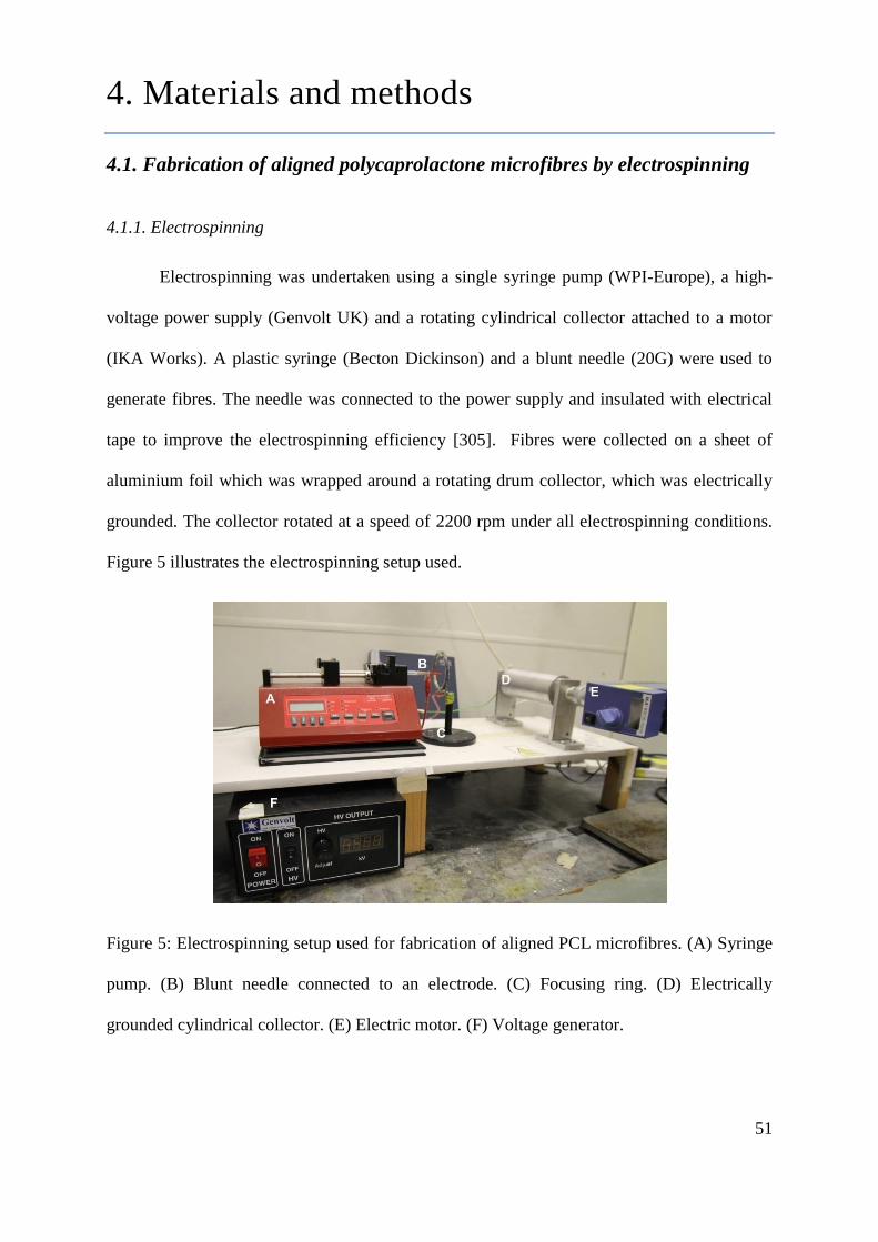
51
4. Materials and methods
4.1. Fabrication of aligned polycaprolactone microfibres by electrospinning
4.1.1. Electrospinning
Electrospinning was undertaken using a single syringe pump (WPI-Europe), a high-
voltage power supply (Genvolt UK) and a rotating cylindrical collector attached to a motor
(IKA Works). A plastic syringe (Becton Dickinson) and a blunt needle (20G) were used to
generate fibres. The needle was connected to the power supply and insulated with electrical
tape to improve the electrospinning efficiency [305]. Fibres were collected on a sheet of
aluminium foil which was wrapped around a rotating drum collector, which was electrically
grounded. The collector rotated at a speed of 2200 rpm under all electrospinning conditions.
Figure 5 illustrates the electrospinning setup used.
Figure 5: Electrospinning setup used for fabrication of aligned PCL microfibres. (A) Syringe
pump. (B) Blunt needle connected to an electrode. (C) Focusing ring. (D) Electrically
grounded cylindrical collector. (E) Electric motor. (F) Voltage generator.

52
4.1.2. Optimization of polycaprolactone molecular weight and solution concentration for
electrospinning aligned microfibres
To determine the feasible polycaprolactone molecular weights and solution
concentrations for electrospinning aligned fibres, three different polycaprolactone molecular
weights (Mn 10,000 g/mol (Mw 14,000 g/mol), Mn 40,000 g/mol (Mw 60,000 g/mol) and Mn
80,000 g/mol (Mw 144,000 g/mol)) were dissolved in dichloromethane (Fisher Scientific UK)
in various concentrations and electrospining was carried out with various processing
conditions on an investigative basis. The concentrations and processing conditions used for
these experiments are summarized in Table 2. For these preliminary studies, PCL fibres were
qualitatively examined using phase-contrast microscopy. Electrospun fibres were cut into ~1
cm × ~2 cm and then, using transparent tape, were removed from the aluminium foil onto
which the fibres were spun. Then, electrospun fibres, together with the transparent tape, were
mounted on a microscope slide for imaging.
4.1.3. Fabrication of aligned polycaprolactone microfibres with different diameter by
electrospinning
Three electrospinning conditions were used to fabricate fibres of three different
diameters from polycaprolatone (PCL; Sigma-Aldrich) of Mn 80,000 g/mol. For the
fabrication of large (8µm) and intermediate (5µm) sized fibres, the polymer was dissolved in
dichloromethane (Fisher Scientific UK) at 20 wt% and 10 wt% concentration, respectively.
Both PCL solutions were electrospun at a distance of 20 cm from the collector for 4 minutes.
For large fibres, the syringe pump flow rate was set to 6 ml/hour and the applied voltage was
18 kV. For intermediate fibres, the flow rate was 4 ml/hr (15 kV). For small fibre (1 µm)
fabrication, PCL was dissolved in a mixture of chloroform (Fisher Scientific UK) and
dicholoromethane (Fisher Scientific UK) (50:50 v/v) to make a 10 wt% PCL solution. The
flow rate was 0.3 ml/hour and the applied voltage was 14 kV. The distance between the

53
needle and the collector was 20 cm and spinning was conducted for 10 minutes. A 27G blunt
needle was used for small fibre fabrication. A summary of the processing conditions used to
electrospin is shown in table 1.
4.1.4. Physical characterization of aligned PCL microfibres with different diameters by
scanning electron microscopy (SEM)
Three fibre groups of 1 µm, 5 m and 8 µm were electrospun independently and three
separate sample batches were studied by SEM for each fibre group. Three parameters were
analyzed: i) fibre diameter; ii) fibre alignment and iii) fibre density. All samples were sputter-
coated with a 20 nm thick gold film before SEM to improve the conduction of the sample.
SEM was conducted using a FEI Sirion field emission gun scanning electron microscope and
parameters were analyzed using National Institutes of Health (NIH) Image J software. An
average of 46 fibres per fibre group was measured for diameter and 38 fibres per fibre group
were measured for alignment. The same images were analyzed for density, which was
measured by quantifying the number of fibres across a fixed sample width of 117 µm. A
reference line was drawn perpendicular to a central fibre and the number of fibres along the
reference line was counted and density calculated by dividing the number of fibres by the
length of the line. Fibre alignment was determined by measuring the angular variance
between fibres. To achieve this, a reference line was drawn parallel to an assigned central
fibre and the angular difference (in degrees) across the sample measured for each fibre. Data
was collected in to groups of 2о. Thus, measurements between 0
о and +/- 2
о were collected in
to one group, between +/- 2o to +/- 4
o in to a second group, with data collected up to +/-12º.
Scaffold depth (z-depth) as determined by confocal microscopy was found to range from 90
µm to 130 µm for all scaffolds.

54
4.2. Preparation of aligned PCL microfibres and control flat surfaces for cell
and tissue culture
4.2.1. Preparation of aligned PCL microfibres for neuronal cell, primary Schwann cell and
dorsal root ganglion (DRG) culture
PCL fibres were physically maintained in position using a medical grade 316 stainless
steel ring (inner diameter = 13 mm, outer diameter = 24 mm). To position scaffolds, a 10
wt% PCL solution in dichloromethane was spread evenly to the bottom surface of the ring
which was immediately placed onto the fibres and left to dry. Scaffolds were cut into square
(24 mm × 24 mm) around the external surface of the ring enabling samples to fit into a 6-well
tissue culture plate. Scaffolds were removed from the aluminium foil onto which the fibres
were electrospun before being glued on the tissue culture plate using the 10 wt% PCL
solution and were left to dry. Samples were sterilized with 70% ethanol for 3 hours and
washed three times with phosphate-buffered saline (PBS) with a final wash left in PBS
overnight to ensure complete removal of potential contaminants. Samples were washed again
three times with PBS before cell culture experiments.
4.2.2. Preparation of PCL thin films for neuronal and primary Schwann cell culture
Cover glasses and PCL films were used as control flat surfaces. PCL films were
fabricated by spin coating. A 10 wt% PCL solution in dichloromethane was used to make
PCL thin films by spin coating. Approximately 0.2 ml of PCL solution was placed on a 19
mm diameter circular cover glass, which was secured on the rotating part of a spin coater.
The solution was spun until the solvent was fully evaporated. PCL films were fixed on the
surface of a well plate by gluing the edge of films using the same solution. Both cover glasses
and PCL films were sterilised with 70% (v/v) ethanol for 30 minutes, followed by three PBS

55
washes with samples left in PBS overnight, as above. Samples were washed again three times
with PBS before cell culture.
4.3. Neuronal cell culture on aligned PCL microfibres
4.3.1. NG108-15 neuronal cell culture
NG108-15 neuronal cells are a cell line generated by the hybrid of mouse
neuroblastoma and rat glioma cells through a Sendai virus-induced fusion method. NG108-15
neuronal cells were obtained from the European Collection of Cell Cultures (ECACC) and
grown in Dulbecco's Modified Eagle Medium (DMEM) (Biosera) containing 10% foetal calf
serum, 1% glutamine, 1% penicillin / streptomycin, and 0.5% amphotericin B in a humidified
atmosphere with 5% CO2 at 37o C. Cells were used for experiments after they became 80% -
90% confluent and experimentation conducted between passage numbers 10 and 20 (P10-
P20).
4.3.2. Investigation on the effect of serum on neuronal cell differentiation and proliferation
study by the Cell-IQTM
live imaging and analysis system.
The Cell-IQTM
system is an automated live imaging and analysis system which
integrates incubator, microscopy and image analysis in one system. To study the effect of
serum on neuronal cell differentiation and proliferation, NG108-15 neuronal cells were
seeded at a density of 3 × 10⁴ cells per well in either serum-free or serum-containing
Dulbecco‟s modified Eagles medium (10% foetal calf serum). In both conditions, cells were
maintained in 5 ml of medium containing 1% glutamine, 1% penicillin / streptomycin and
0.5% amphotericin B in 6 well-tissue culture plate. Cells were maintained in a humidified
atmosphere with 5% CO2 at 37°C for 4 days. After seeding, cells were incubated overnight
before starting imaging to allow cells to adhere on the surface. Live imaging and image
analysis were conducted by the Cell-IQTM
system. Three random areas on the culture plate

56
were selected per well and set on the Cell-IQTM
system for automatic imaging every 40
minutes for a 4 day culture period. Neuronal cell differentiation was studied by measuring
total neurite length per field-of-view (Figure 6A) while the proliferation of neuronal cells was
analysed by quantifying the total area occupied by the cells (Figure 6B). Both quantitative
analyses was conducted on the Cell-IQTM
system.
Figure 6: (A) Neurite tracing (blue) on the Cell-IQTM
software for neurite measurement. (B)
Area occupied by NG108-15 neuronal cells (purple) detected by the Cell-IQTM
software for
cell proliferation analysis. Scale bar = 140 µm.
4.3.3. NG108-15 neuronal cell culture on aligned PCL microfibres and control flat surfaces
NG108-15 neuronal cells were trypsinized and 3 × 10⁴ cells seeded directly on to PCL
fibre samples contained within 6-well plates in 5 ml of serum-free Dulbecco's modified
Eagles medium (DMEM) containing 1% glutamine, 1% penicillin / streptomycin and 0.5%
amphotericin B. Cultures were maintained for 4 days, with half of the medium removed and
replaced with fresh medium on day 2. Same culture conditions were conducted on control flat
surfaces (cover glasses, PCL films and tissue culture polystyrene) in 6-well plates.
As reported in section 3.2.1, it was found that serum-free medium promoted NG108-
15 neuronal cell differentiation i.e. neurite growth while serum-containing medium
stimulated cell proliferation but not differentiation. Therefore, in this experiment, serum-free
57
medium was used for studying neuronal cell differentiation on aligned PCL microfibres and
control flat surfaces.
4.3.4. F-actin labelling with phalloidin-tetramethylrhodamine B isothiocyanate (phalloidin-
TRITC) for visualization of neuronal cells by confocal microscopy
Samples containing cultures of NG108-15 neuronal cells were carefully washed once
with PBS and fixed with 10% (v/v) formalin (diluted in PBS) for 30 minutes at room
temperature. After washing once with PBS, cells were permeabilized with 1% (v/v) Triton-X-
100 (diluted in PBS) for 1 minute at 4 °C, followed by washing with PBS (×3). Cells were
incubated with phallodin-TRITC (1:1000 dilution in PBS) (Sigma-Aldrich) for 30 minutes at
room temperature before washing with PBS (×3). Finally, cells were covered in PBS for
imaging by confocal microscopy. Cells were imaged using an upright Zeiss LSM 510
confocal microscope using a helium-neon laser (543 nm) for tetramethylrhodamine B
isothiocyanate (TRITC) excitation (λex = 540-545 nm / λem = 570-573 nm). Samples were
processed for 3D imaging by „z-stacking‟ using an average of 40 slices per sample/image
with z-depths ranging from 90 to 130 µm. Representative z-stack images were displayed as
single plane images.
4.3.5. Immunolabelling of neuronal cells for a neuronal cell specific marker, β III-tubulin for
visualization by confocal microscopy
Samples containing cultures of NG108-15 neuronal cells were washed three times
with PBS and fixed with 4% (v/v) paraformaldehyde for 20 minutes, permeabilized with
0.1% Triton X-100 for 20 minutes followed by washing with PBS (×3). Unreactive binding
sites were blocked with 3% bovine serum albumin (BSA) and cells incubated overnight with
a mouse anti-β III-tubulin antibody (neuronal cell marker for NG108-15 neuronal cell
culture) (1:2000) (Promega, UK) diluted in 1% BSA at 4 ºC. Cells were then washed three
58
times with PBS before being incubated with Texas Red-conjugated anti-mouse IgG antibody
(1:100 dilution in 1% BSA) (Vector Labs, USA) for 90 minutes. After washing once with
PBS, 4′,6-diamidino-2-phenylindole dihydrochloride (DAPI) (Sigma Aldrich) (300 nM) was
added to stain for nuclei and cells immersed for 15 minutes at room temperature, washed
again three times with PBS before imaging. An upright Zeiss LSM 510 confocal microscope
using a helium-neon laser (543 nm) for Texas Red excitation (λex = 589nm / λem = 615 nm).
Nuclei were visualized by two photon excitation using a Ti:sapphire laser (800 nm) for DAPI
(λex= 358 nm / λem = 461 nm). Samples were processed for 3D imaging by „z-stacking‟ using
an average of 50 slices per sample/image with z-depths ranging from 90 to 130 µm.
Representative z-stack images were displayed as single plane images and combined to show
3D composite images as presented in Figure 18.
4.3.6. Live/dead measurement of neuronal cells
Culture medium was removed from cell samples and incubated in fresh serum-free
medium containing 0.001% (v/v) Syto-9TM
(Invitrogen) and 0.0015% (v/v) propidium iodide
(Invitrogen) at 37oC / 5% CO2 for 15 minutes. After replacing with fresh medium, cells were
imaged using an upright Zeiss LSM 510 confocal microscope with an argon ion laser (488
nm) for Syto-9 (λex = 494 nm / λem = 515 nm) and a helium-neon laser (543 nm) for
propidium iodide (λex = 536 nm / λem = 617 nm). Three fields of view were imaged with the
acquisition of 80 to 200 cells per experiment enabling data to be expressed as a percentage of
live versus dead cells ± SEM. Quantification of live and dead cells was undertaken using the
3D Objects Counter software on NIH Image J (threshold = 40 to 90) and analysis conducted
on z-stack images across a z-depth range of 90 to 130 µm.

59
4.3.7. Neurite outgrowth assessment
Fields-of-view selected at random by confocal microscopy were analysed using
neurite tracer software (NIH Image J). Three parameters were examined to assess
differentiation: i) the maximum neurite length ; ii) the number of neurites per neuron and iii)
the percentage of neurite-bearing neurons. The length of each neurite was taken from the tip
of the neurite to the cell body. An average of 80 neurites were measured for each condition
for maximum neurite length and the number of neurites per neuron, with three independent
sample measurements made (n=3). The percentage of neurite-bearing neurons comprised the
total number of neurons per field-of-view (numerator) divided by the total number of cells
identified as positively stained nuclei (denominator), using 3D Objects Counter software
(threshold = 100 to 190, NIH Image J) and analysis conducted on z-stack images across a z-
depth range of 90 to 130 µm.
4.3.8. Quantification of the total number of NG108-15 neuronal cell per unit surface area on
aligned PCL microfibres
The total number of NG108-15 neuronal cell per unit surface area on aligned PCL
microfibres and flat surfaces was assessed after 4 days in culture by quantifying the total
number of cells labelled with Syto-9TM
and propidium iodide over an area of 1.42 mm
2 (1.19
mm × 1.19 mm). The total surface area of aligned PCL microfibres was calculated using the
following formulation:
Total surface area =2π× fibre diameter in mm
2 ×fibre length × number of fibre
= 2π× fibre diameter in mm
2 ×1.19 mm ×fibre density×1.19 mm

60
The total number of NG108-15 neuronal cell per unit surface area comprised the total
number of cells quantified per an area of 1.42 mm2 divided by the total surface area. Three
randomly selected fields-of-view per sample obtained by confocal microscopy were analysed
using the 3D Objects Counter software on NIH Image J (threshold = 40 to 90)
4.4. Primary Schwann cells cultured on aligned PCL microfibres
4.4.1. Isolation and culture of primary Schwann cells
Primary Schwann cells were isolated from the sciatic nerve of adult male Wistar rats
(age 10-12 weeks old) which were sacrificed by a Schedule I method in accordance to the
Animals (Scientific Procedures) Act 1986. This study employed a novel technique for
Schwann cell isolation from adult rat nerve with average Schwann cell purities of 97% which
was developed by Kaewkhaw and Haycock [306]. This method is based on a selective culture
medium that stimulates Schwann cell growth (due to the mitogens such as forskolin, N2
supplement and bovine pituitary extract) but simultaneously inhibits fibroblast overgrowth
(due to an inhibitory substance, D-valine). The method exploits the preferential capacity of
Schwann cells to metabolize D-valine since Schwann cells express a higher level of a D-
amino acid oxidase than fibroblasts.
Briefly, the sciatic nerve was removed by bilateral dissection and immersed in
chilled DMEM containing 1% penicillin/streptomycin. Epineurium free fascicles were
dissociated, cut into smaller fragments and digested with 0.05% collagenase at 37oC for 60
minutes. The resultant cell suspension was filtered using a 40 µm cell strainer (BD Falcon)
and centrifuged at 400 g for 6 minutes, supernatant removed and cell pellet washed with 10
ml of DMEM containing 10% FCS. The pellet was re-suspended in 1 ml of Schwann cell
medium (DMEM D-valine (PAA), 2 mM glutamine, 10% FCS, 1% N2 supplement (Gibco
BRL, UK), 20 µg/ml bovine pituitary extract, 5 µM forskolin, 1% penicillin/streptomycin and

61
0.25% amphotericin B). 500 µl of cell suspension was added into 2 ml Schwann cell medium
in a Petri dish pre-coated with 1 µg/cm2 laminin and 0.01 mg/cm
2 poly-l-lysine (Sigma
Aldrich). Cells were incubated at 37oC / 5% CO2. 1 ml of fresh Schwann cell medium was
added on day 7. The medium was replenished on day 11 and subsequently changed every 2
days until confluent. Cells were used for experimentation between passage number 3 and 10
(P3-P10).
4.4.2. Primary Schwann cell culture on aligned PCL microfibres and control flat surfaces
Cells were trypsinized and 5 × 10⁵ cells seeded directly on to PCL fibre samples
contained within 6-well plates in 4 ml of DMEM D-valine (PAA) containing 2 mM
glutamine, 10% FCS, 1% N2 supplement (Gibco BRL, UK), 20 µg/ml bovine pituitary
extract, 5 µM forskolin, 1% penicillin/streptomycin and 0.25% amphotericin B. Cultures
were maintained for 8 days, with half of the medium removed and replaced with fresh
medium every 2 days. Same culture conditions were conducted on control flat surfaces (cover
glasses, PCL films and tissue culture polystyrene) in 6-well plates.
4.4.3. Immunolabelling for S100β Schwann cell marker by confocal microscopy
Samples containing cultures of primary rat Schwann cells were washed three times
with PBS and fixed with 4% (v/v) paraformaldehyde for 20 minutes, permeabilized with
0.1% Triton X-100 for 20 minutes followed by washing with PBS (×3). Unreactive binding
sites were blocked with 3% bovine serum albumin (BSA) and cells incubated overnight with
a polyclonal rabbit anti-S100β (Schwann cell marker for Schwann cell cultures, co-cultures
or DRG samples) (1:250) (Dako, Denmark) diluted in 1% BSA at 4 ºC. Cells were then
washed three times with PBS before being incubated with FITC-conjugated secondary anti-
rabbit IgG antibody (1:100 dilution in 1% BSA) (Vector Labs, USA) for 90 minutes. After
washing once with PBS, 4′,6-diamidino-2-phenylindole dihydrochloride (DAPI) (Sigma

62
Aldrich) (300 nM) was added to stain for nuclei and cells immersed for 15 minutes at room
temperature, washed again three times with PBS before imaging. Schwann cells were imaged
using an upright Zeiss LSM 510 confocal microscope using an argon ion laser (488 nm) for
FITC excitation (λex= 495 nm / λem = 521 nm). Nuclei were visualized by two photon
excitation using a Ti:sapphire laser (716 nm) for DAPI (λex= 358 nm / λem = 461 nm).
Samples were processed for 3D imaging by „z-stacking‟ using an average of 50 slices per
sample/image with z-depths ranging from 90 to 130 µm. Representative z-stack images were
displayed as single plane images and combined to show 3D composite images as presented in
Figure 26.
4.4.4. Live/dead measurement of primary Schwann cells for cell viability assessment
Culture medium was removed from cell samples and incubated in fresh Schwann cell
medium containing 0.001% Syto-9TM
(Invitrogen) and 0.0015% propidium iodide
(Invitrogen) at 37oC / 5% CO2 for 15 minutes. Then, cells were carefully washed with PBS
three times before adding fresh warm Schwann cell medium. Cells were imaged using an
upright Zeiss LSM 510 confocal microscope with an argon ion laser for Syto-9 (λex = 494 nm
/ λem = 515 nm) and a helium-neon laser for propidium iodide (λex = 536 nm / λem = 617 nm).
Three fields of view were imaged with the acquisition of an average of 500 cells per
experiment enabling data to be expressed as a percentage of live versus dead cells ± SEM.
Quantification of live and dead cells was undertaken using the 3D Objects Counter software
on NIH Image J (threshold = 40 to 90) and analysis conducted on z-stack images across a z-
depth range of 90 to 130 µm.

63
4.4.5. Assessment of primary Schwann cell morphology
The bipolar morphology of primary Schwann cells was assessed by quantifying the
tip-to-tip length of the cells. Randomly selected fields-of-view obtained by confocal
microscopy were analysed using the ruler tool in NIH Image J. An average of 100 cells per
condition was examined and the mean cell length was established from three independent
experiments and analysis conducted on z-stack images across a z-depth range of 90 to 130
µm.
4.4.6. Quantification of the total number of primary Schwann cell per unit surface area on
aligned PCL microfibres
The total number of primary Schwann cell per unit surface area on aligned PCL
microfibres and flat surfaces was assessed after 4 days in culture by quantifying the total
number of cells labelled with Syto-9TM
and propidium iodide over an area of 1.42 mm
2 (1.19
mm × 1.19 mm). The total surface area of aligned PCL microfibres was calculated using the
following formulation:
Total surface area =2π× fibre diameter in mm
2 ×fibre length × number of fibre
= 2π× fibre diameter in mm
2 ×1.19 mm ×fibre density×1.19 mm
The total number of NG108-15 neuronal cell per unit surface area comprised the total
number of cells quantified per an area of 1.42 mm2 divided by the total surface area. Three
randomly selected fields-of-view per sample obtained by confocal microscopy were analysed
using the 3D Objects Counter software on NIH Image J (threshold = 40 to 90).
64
4.5. Co-culture of neuronal cells and Schwann cells on aligned PCL
microfibres
2.5.1. Co-culture of NG108-15 neuronal cells and Schwann cells on aligned PCL microfibres
Schwann cells were initially seeded directly on to PCL fibre samples at a density of 5
× 105 cells per well and cultured for 8 days in Schwann cell medium. On day 8, Schwann cell
medium was removed and 5 ml of co-culture medium was added to the cells. NG108-15
neuronal cells were seeded at a density of 7 × 10³ cells per well to establish a neuronal / glial
cell co-culture. The co-culture medium was made up of a mixture of DMEM (Biosera) and
Ham‟s F12 medium (Biosera) at a 1:1 ratio (v/v) and was supplemented with 1 % L-
glutamine, 1% penicillin/streptomycin, and 1% N2 supplement. Co-cultures were maintained
for 4 days at 37oC, 5% CO2. Half of the medium was replaced with fresh medium on day two.
4.5.2. Dorsal root ganglion (DRG) explant cultures
Rat dorsal root ganglions (DRG) were used to establish a co-culture of primary
neuronal cells and Schwann cells. DRGs contain both primary sensory neuronal cells and
primary Schwann cells when explanted. In this study, DRGs were isolated from adult male
Wistar rats. Experiments were carried out in accordance with the institutional guidelines for
animal care and in accordance to the Animals (Scientific Procedures) Act 1986 (Schedule I
killing). Immediately after decapitation the vertebral column was removed, Muscles were
removed and the vertebral column was sectioned into 1-2 cm lengths before a sagittal cut
exposing the spinal cord. Then, the spinal cord was removed from the spinal canal until the
DRG located lateral to the spinal cord was visible. DRGs were removed from the cervical,
thoracic, and lumbar region with fine forceps and pooled into ice cold PBS. Nerve roots were
trimmed from DRGs before explanting on PCL fibres and culture surfaces.

65
4.5.3. Dorsal root ganglion (DRG) explants cultured on aligned PCL microfibres with
different diameters.
DRGs isolated from adult male Wistar rats (age between 5-12 weeks) were used for
this experiment. PCL fibres were washed three times with PBS and then equilibrated for 30
minutes in culture medium (Dulbecco‟s modified Eagles medium containing 4 mM
glutamine, 25 mM glucose, 100 U/ml penicillin, 100 mg/ml streptomycin and 10% foetal calf
serum). Three DRGs were placed onto individual PCL fibre samples using forceps spaced
approximately 1 - 2 mm apart and incubated for 10 days in a humidified atmosphere with 5%
CO2 at 37ºC. The culture medium was replenished every 2 days. Neurite outgrowth from
DRGs on PCL fibres was determined for each fibre diameter (1 µm, 5 µm and 8 µm) and
experiments repeated three times (with 3 independent experiments for identical conditions).
4.5.4. Immunolabelling for S100β and βIII-tubulin for visualization of Schwann cells and
neuronal cells in co-culture by confocal microscopy
Co-cultures of NG108-15 neuronal and Schwann cells were double-labelled for both a
neuronal cell marker, βIII-tubulin and a Schwann cell marker, S100β to distinguish the
respective cell types in co-culture. Samples containing co-cultures of neuronal and Schwann
cells were washed three times with PBS and fixed with 4% (v/v) paraformaldehyde for 20
minutes, permeabilized with 0.1% Triton X-100 for 20 minutes followed by washing with
PBS (×3). Unreactive binding sites were blocked with 3% bovine serum albumin (BSA) and
cells incubated overnight with a polyclonal rabbit anti-S100β antibody (1:250) (Dako,
Denmark) and a mouse anti-β III-tubulin antibody (1:2000) (Promega, UK) diluted in 1%
BSA at 4ºC. Cells were then washed three times with PBS before being incubated with FITC-
conjugated secondary anti-rabbit IgG and Texas Red-conjugated anti-mouse IgG antibody
(1:100 dilution in 1% BSA) (Vector Labs, USA) for 90 minutes. Co-cultures were washed
three times with PBS before imaging.

66
Co-cultures were imaged using an upright Zeiss LSM 510 confocal microscope using
an argon ion laser (488 nm) for FITC excitation (λex= 495 nm / λem = 521 nm) to visualize
Schwann cells and a helium-neon laser (543 nm) for Texas Red excitation (λex = 589nm / λem
= 615 nm) to visualize NG108-15 neuronal cells. Samples were processed for 3D imaging by
„z-stacking‟ using an average of 50 slices per sample/image with z-depths ranging from 90 to
130 µm. Representative z-stack images were displayed as single plane images and combined
to show 3D composite images as presented in Figure 18.
4.5.5. Neurite outgrowth assessment in NG108-15 neuronal- Schwann cell co-culture
In the NG108-15 neuronal-Schwann cell co-culture study, neurite growth was
assessed by measuring the maxium neurite length (the longest neurite measured in a cell).
Fields-of-view selected at random by confocal microscopy were analysed using neurite tracer
software (NIH Image J). The length of each neurite was taken from the tip of the neurite to
the point where the neurite meets the cell body. An average of 48 neurites were measured for
each condition with three independent sample measurements made (n=3). The analysis was
conducted on z-stack images across a z-depth range of 90 to 130 µm. Neurite measurement
from single cultures of NG108-15 neuronal cells on PCL fibres was used as control, obtained
from earlier NG108-15 neuronal cell culture study (see 2.3.).

67
4.5.6. Axon outgrowth and Schwann cell migration assessment in neuronal-Schwann cell co-
cultures derived from DRGs explants.
In this study, axon outgrowth was assessed by measuring the distance between the
DRG body and the end of the longest axon observed. Schwann cell migration was analysed
by measuring the distance from the DRG body to the furthest Schwann cells observed from
the DRG body after 10 days in culture. Sequential-tiled images of axons and Schwann cells
recorded by confocal microscopy were merged using Adobe Photoshop CS3. Measurements
were conducted using the ruler tool in NIH Image J. Six measurements of neurite length and
Schwann cell migration distance were conducted for each condition with three independent
sample measurements made (n=3).
4.6. Myelination studies in neuronal-Schwann cell co-culture on aligned PCL
microfibres
4.6.1. Dorsal root ganglion (DRG) culture on aligned PCL microfibres and laminin-coated
tissue culture plate for myelination study
DRG extraction was carried out as described in section 2.5.2. DRGs extracted from
adult male Wistar rats (age between 5-12 weeks) were used for experimentation. Sterile PCL
fibres, contained in 6 well-plates, were washed three times with PBS and then equilibrated for
30 minutes in 500 µl of culture medium. Two DRGs were placed onto individual PCL fibre
samples (fibre diameter, 1 µm) using forceps spaced approximately 1-2 mm apart and then,
an additional 300 µl of culture medium was added to make a total of 800 µl culture medium.
Tissue culture plates (6 well-plates) were pre-coated with 1 µg/cm2 laminin and used as
control culture surfaces. DRGs were maintained in either standard DMEM or DMEM with
D-valine (PAA) containing 5 µM forskolin for medium optimization for myelination. Both
medium were supplemented with 10% foetal calf serum, 2 mM glutamine, 1% N2

68
supplement (Gibco BRL, UK) 1% penicillin/streptomycin, 0.25% amphotericin B and 50
ng/ml nerve growth factor-β (NGF-β) (Sigma-Aldrich). DRGs were incubated for 7 days in a
humidified atmosphere with 5% CO2 at 37°C to allow axon and Schwann cell outgrowth.
After 7 days, ascorbic acid (Sigma-Aldrich) was added in culture medium to induce
myelination (final concentration, 50µg/ml). Ascorbic acid treatment was continued for 14
days before analysing myelin expression.
4.6.2. Dorsal root ganglion (DRG) dissociation and culture
Rat DRGs were extracted from the vertebral column as described earlier (see 2.5.2).
Nerve roots were trimmed and subsequently DRGs were incubated in 1.25% (w/v)
collagenase type IV (dissolved in DMEM) for 1 hour at 37°C. Then, DRGs were washed
gently with fresh DMEM once, followed with incubation with 2.5% (w/v) trypsin (dissolved
in DMEM) for 30 minutes at 37°c. Foetal calf serum was added to deactivate trypsin and
DRGs were then washed with fresh DMEM (×3). DRGs were then mechanically dissociated
by trituration with a glass pipette in DMEM. The resultant cell suspension was filtered
through a 70 µm cell strainer, centrifuged at 300 g for 5 minutes and subsequently, the pellet
was resuspended in 500 µl fresh DMEM. Cell suspension was transferred into a universal
tube by flowing the suspension onto the side of the tube which was pre-coated with 15%
(w/v) bovine serum albumin (BSA) (Sigma-Aldrich), followed with centrifugation at 500 g
for 10 minutes. After aspirating the supernatant, cells were resuspended in DMEM containing
1% penicillin/streptomycin and 0.25% amphotericin B.

69
4.6.3. Co-culture of primary neuronal cells and Schwann cells established from dissociated
dorsal root ganglion (DRG) for myelination study
Primary Schwann cells were seeded at a density of 7 x 10⁴
cells per well in 24 well-
plate pre-coated with 1 µg/cm2 laminin (Sigma Aldrich) and 0.01 mg/cm
2 poly-l-lysine
(Sigma Aldrich). Cells were maintained in Schwann cell medium (see 2.4.1.) in a humidified
atmosphere with 5% CO2 at 37°C for 3 days. Then, primary neuronal/Schwann cell co-
cultures were established by seeding primary neurons generated from dissociated DRGs on
the pre-cultured Schwann cells. Co-cultures were maintained for 3 days in medium as listed
below before starting ascorbic acid treatment for inducing myelination:
Standard DMEM containing 10 % foetal calf serum, 2 mM glutamine, 1% N2
supplement (Gibco BRL, UK) 1% penicillin/streptomycin, 0.25% amphotericin B and
50 ng/ml nerve growth factor-β (NGF-β) (Sigma-Aldrich)
Serum free standard DMEM containing 2 mM glutamine, 1% N2 supplement (Gibco
BRL, UK) 1% penicillin/streptomycin, 0.25% amphotericin B and 50 ng/ml nerve
growth factor-β (NGF-β) (Sigma-Aldrich)
DMEM D-valine (PAA laboratories) containing 10 % foetal calf serum, 5 µM
forskolin, 2 mM glutamine, 1% N2 supplement (Gibco BRL, UK) 1%
penicillin/streptomycin, 0.25% amphotericin B and 50 ng/ml nerve growth factor-β
(NGF-β) (Sigma-Aldrich)
Serum free DMEM D-valine (PAA laboratories) containing 5 µM forskolin, 2 mM
glutamine, 1% N2 supplement (Gibco BRL, UK) 1% penicillin/streptomycin, 0.25%
amphotericin B and 50 ng/ml nerve growth factor-β (NGF-β) (Sigma-Aldrich)
Co-cultures were treated with 50 µg/ml L-ascorbic acid (Sigma-Aldrich) for 14 days, with the
medium changed every 2 days before analysing for myelin expression.

70
4.6.4. Co-culture of primary neuronal cells and Schwann cells established from dissociated
dorsal root ganglion (DRG) on aligned PCL microfibres for myelination study
Primary Schwann cells were initially seeded directly on to PCL fibre samples
(diameter = ~1 µm) at a density of 5 × 10⁵ cells per well and cultured in Schwann cell
medium Cells in a humidified atmosphere with 5% CO2 at 37°C for 8 days. Then, primary
neuronal/Schwann cell co-cultures were established by seeding primary neurons generated
from dissociated DRGs on the pre-cultured Schwann cells. Co-cultures were maintained for 3
days in serum free DMEM D-valine (PAA laboratories) containing 5 µM forskolin, 2 mM
glutamine, 1% N2 supplement (Gibco BRL, UK) 1% penicillin/streptomycin, 0.25%
amphotericin B and 50 ng/ml nerve growth factor-β (NGF-β) (Sigma-Aldrich) before starting
ascorbic acid treatment for inducing myelination. Co-cultures were treated with 50 µg/ml L-
ascorbic acid (Sigma-Aldrich) for 14 days, with the medium changed every 2 days before
analysing for myelin expression by transmission electron microscopy.
4.6.5. Immunolabelling for myelin basic protein and myelin protein zero for the detection of
myelin expression in dorsal root ganglion (DRG) explants culture and dissociated DRG
culture
Samples containing cultures of whole DRGs or dissociated DRGs were washed three
times with PBS and fixed with 4% (v/v) paraformaldehyde for 20 minutes, permeabilized
with 0.1% Triton X-100 for 20 minutes followed by washing with PBS (×3). Unreactive
binding sites were blocked with 3% bovine serum albumin (BSA) and cells incubated
overnight with a mouse monoclonal anti-myelin basic protein (MBP) antibody (1:250) (Dako,
Denmark) and a rabbit polyclonal anti-myelin protein zero (P0) antibody (1:250) (Abcam)
diluted in 1% BSA at 4 ºC. Cells were then washed three times with PBS before being
incubated with Texas Red-conjugated secondary anti-mouse IgG antibody and FITC-
conjugated secondary anti-rabbit IgG antibody (1:100 dilution in 1% BSA) (Vector Labs,
71
USA) for 90 minutes. After washing once with PBS, 4′,6-diamidino-2-phenylindole
dihydrochloride (DAPI) (Sigma Aldrich) (300 nM) was added to stain for nuclei and cells
immersed for 15 minutes at room temperature, washed again three times with PBS before
imaging. Samples were imaged using an epifluorescence microscope (Axon ImageXpress,
Molecular Devices, USA) for Texas red excitation (λex = 589nm / λem = 615 nm) and FITC
excitation (λex= 495 nm / λem = 521 nm) to detect MBP and P0 expressions, respectively.
4.6.6. Assessment of myelin expression by Sudan Black B staining
Sudan Black B was used to detect myelination in cell cultures by staining lipids in the
myelin sheath. For Sudan Black B staining, sensory neuronal cells derived from dissociated
DRGs were co-cultured with primary Schwann cells, which was pre-cultured on a cover slip
(diameter = 13 mm). Co-cultures were washed with PBS three times and then, fixed with
3.7% (v/v) paraformaldehyde (in PBS) overnight. After washing with PBS once, co-cultures
were post-fixed with 0.1% (v/v) osmium tetroxide (in PBS) for 1 hour at room temperature.
Co-cultures were washed three times, dehydrated through a graded series of ethanol (20%,
50% and 70%) for 5 minutes in each concentration. Co-cultures were then stained with 0.5%
(w/v) Sudan Black B (Sigma-Aldrich) in 70% ethanol for 1 hour at room temperature before
being rehydrated through a graded series of ethanol (70% for 1 minute, 50% for 5 minutes
and 25% for 5 minutes). Co-cultures were washed with PBS twice and mounted in glycerol
gelatine on a microscope slide before imaging by a Leica light microscope. To make glycerol
gelatine mounting medium, 2.5g of gelatine was dissolved in 25ml of distilled water with
gentle heat until fully dissolved. Then, 25 ml of glycerol was mixed in gelatine solution.

72
4.6.7. Examination of the myelin sheath in rat sciatic nerves by transmission electron
microscopy
Rat sciatic nerves were cut into small pieces (approximately 1 mm length) and fixed
with 3% (v/v) glutaraldehyde (Sigma-Aldrich) in PBS overnight at 4°C. Samples were then
washed with PBS twice with 10 minutes intervals. Samples were post-fixed with 1% (v/v)
osmium tetroxide (Sigma-Aldrich) in PBS for 2 hours at room temperature, washed with
distilled water for 10 minutes, and dehydrated through a graded series of ethanol as follows:
1. 75% ethanol for 15 minutes,
2. 95% ethanol for 15 minutes,
3. 100% ethanol for 15 minutes, twice,
4. 100% ethanol dried over anhydrous copper sulphate for 15 minutes, twice.
Samples were left in propylene oxide for 15 minutes, twice and then, infiltrated with a
mixture of propylene oxide (Sigma-Aldrich) and Araldite resin (1:1 v/v) overnight at room
temperature. Samples were further infiltrated with full strength Araldite resin for 6 hours at
room temperature before being embedded in fresh Araldite resin for 72 hours at 60°C.
Araldite resin (Agar Scientific) was made by mixing 10 ml of Araldite CY212 resin, 10 ml of
Dodecenyl Succinic Anhydride (DDSA) hardener and 20 drops of Benzyl Di-Methyl Amine
(BDMA) accelerator.
Samples were cut transversely into ultrathin sections (thickness = 90 nm) by a
Reichert Ultracut E ultramicrotome. Sections were stained with 3% aqueous uranyl acetate
(Sigma-Aldrich) for 30 minutes, followed by staining with Reynold‟s lead citrate (Sigma-
Aldrich) before imaging by a FEI Tecnai transmission electron microscope at an accelerating
voltage of 80 kV.

73
4.6.8. Examination of myelination in neuronal-Schwann cell co-cultures on aligned PCL
microfibers by transmission electron microscopy (TEM)
Neuronal-Schwann cell co-cultures were established as described in section 4.6.4. Co-
culture of primary neuronal cells and Schwann cells established from dissociated dorsal root
ganglion (DRG) on aligned PCL microfibres for myelination studyNeuronal-Schwann cell
co-cultures were maintained on aligned PCL microfibers (diameter = 1 µm) in serum free
standard DMEM containing 2 mM glutamine, 1% N2 supplement (Gibco BRL, UK) 1%
penicillin/streptomycin, 0.25% amphotericin B and 50 ng/ml nerve growth factor-β (NGF-β)
(Sigma-Aldrich). This medium was used because possible myelin expression was detected in
this medium as revealed by Sudan Black B staining. Co-cultures were treated with 50 µg/ml
L-ascorbic acid (Sigma-Aldrich) for 14 days.
Co-cultures were fixed with 3% (v/v) glutaraldehyde (Sigma-Aldrich) in PBS
overnight at 4°C. Samples were then washed with PBS twice with 10 minutes intervals.
Samples were post-fixed with 1% (v/v) osmium tetroxide (Sigma-Aldrich) in PBS for 2 hours
at room temperature, washed with distilled water for 10 minutes, and dehydrated through a
graded series of ethanol as follows:
1. 75% ethanol for 15 minutes,
2. 95% ethanol for 15 minutes,
3. 100% ethanol for 15 minutes, twice,
4. 100% ethanol dried over anhydrous copper sulphate for 15 minutes, twice.
Samples were infiltrated with a mixture of ethanol and Spurr resin (1:1 v/v) overnight
at room temperature and further infiltrated with full strength Spurr resin for 6 hours at room
temperature. Aligned PCL microfibres, with neuronal-Schwann cell co-cultures were bundled
before being embedded in fresh Spurr resin for 72 hours at 60°C. Spurr resin (Agar
Scientific) was made by mixing 5 g of ERL 4206 epoxy resin, 3 g Diglycidyl ether of
74
polypropylene glycol (DER 736) epoxy resin flexibilizer, 12 g of Nonenyl succinic anhydride
(NSA) and 0.2 g of dimethylaminoethanol (DMAE) (S-1) accelerator.
Samples were cut transversely into ultrathin sections (thickness = 90 nm) by a
Reichert Ultracut E ultramicrotome. Sections were stained with 3% aqueous uranyl acetate
(Sigma-Aldrich) for 30 minutes, followed by staining with Reynold‟s lead citrate (Sigma-
Aldrich) before imaging by a FEI Tecnai transmission electron microscope at an accelerating
voltage of 80 kV.
4.7. Statistical Analysis
Statistical analysis was performed by using GraphPad Instat (GraphPad Software,
USA). One way analysis of variance, incorporating a multiple comparison Tukey - Kramer‟s
post test (if p < 0.05), was conducted to analyze the difference between data. Data was
reported as mean ± SEM except for fibre diameter measurement which was reported as mean
± SD.
75
5. Results
5.1. Fabrication of aligned polycaprolactone (PCL) microfibres by
electrospinning
5.1.1. Optimization of polycaprolactone (PCL) molecular weight and solution concentration
for electrospinning aligned microfibres
In this preliminary study, PCL with molecular weights of Mn 10,000 g/mol, Mn 40,000
g/mol and Mn 80,000 g/mol were electrospun using a range of solution concentrations to
determine the optimal molecular weight and solution concentration for fabrication of aligned
PCL microfibres. Processing conditions such as applied voltage, flow rate and needle-to-
collector distance were varied, observing the ejection of a polymer jet from the needle
(Figure 7). The resultant fibres were qualitatively analysed initially by phase contrast
microscopy for fibre formation and fibre alignment. Processing conditions used for
electrospinning, together with the observations are summarised in Table 1.
For PCL Mn 10,000 g/mol, there was no ejection of a polymer jet observed when
electrospinning was conducted on a PCL solution with a concentration below 40% (w/w).
Instead, a spray of PCL solution was observed. Jet formation was observed with an increment
of the concentration to 50% but no fibres were successfully collected. A further increment in
solution concentration was unable to be conducted because PCL cannot fully dissolved in
dicholoromethane, hence electrospinning was not conducted for higher solution
concentrations. Similarly, for PCL Mn 40,000 g/mol ejection of a polymer jet was unable to
be achieved when electrospinning was conducted on PCL solutions with a concentration
lower than 18% (w/w). A polymer jet was observed with up to a concentration to 30% (w/w),
however, a mesh-like polymer sheet was collected and no evidence of aligned fibres was
observed (Figure 8A). Electrospinning of a 40% (w/w) PCL solution resulted in the formation
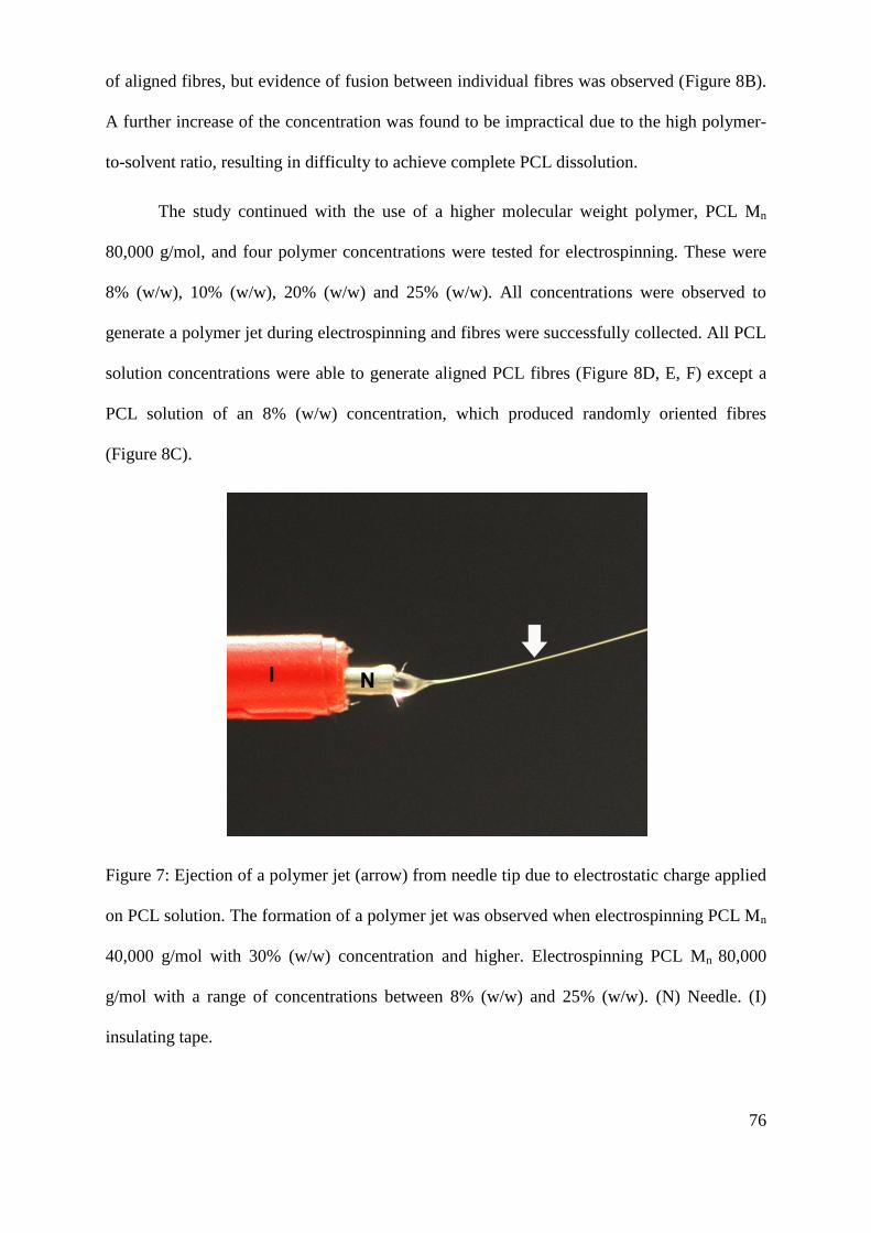
76
of aligned fibres, but evidence of fusion between individual fibres was observed (Figure 8B).
A further increase of the concentration was found to be impractical due to the high polymer-
to-solvent ratio, resulting in difficulty to achieve complete PCL dissolution.
The study continued with the use of a higher molecular weight polymer, PCL Mn
80,000 g/mol, and four polymer concentrations were tested for electrospinning. These were
8% (w/w), 10% (w/w), 20% (w/w) and 25% (w/w). All concentrations were observed to
generate a polymer jet during electrospinning and fibres were successfully collected. All PCL
solution concentrations were able to generate aligned PCL fibres (Figure 8D, E, F) except a
PCL solution of an 8% (w/w) concentration, which produced randomly oriented fibres
(Figure 8C).
Figure 7: Ejection of a polymer jet (arrow) from needle tip due to electrostatic charge applied
on PCL solution. The formation of a polymer jet was observed when electrospinning PCL Mn
40,000 g/mol with 30% (w/w) concentration and higher. Electrospinning PCL Mn 80,000
g/mol with a range of concentrations between 8% (w/w) and 25% (w/w). (N) Needle. (I)
insulating tape.

77
PCL Mn
(g/mol)
PCL
Concentration
(w/w %)
Voltage
(kV)
Flow
rate
(ml/hr)
Distance
* (cm) Observations
~ 10,000
< 30 - - -
No jet formation was
observed at all voltages, flow
rates and distances.
40 - - -
No jet formation was
observed all voltages, flow
rates and distances.
50 8 4 7.5
Jet formation was observed at
all voltages, flow rates and
distances.
~ 40,000
< 18 - - -
No jet formation was
observed all voltages, flow
rates and distances.
30 12-15 4 10
Jet formation was observed
but no aligned fibres were
generated (Figure 8A)
40 12 2-10 10
Aligned fibres were generated
with possible fusion between
the fibres (Figure 8B)
~ 80,000
8 9-11 1 8-15 Randomly oriented fibres
were generated (Figure 8C)
10 12 2-10 10-20 Aligned fibres were generated
(Figure 8D)
20 12 2-12 10-20 Aligned fibres were generated
(Figure 8E)
25 19-20 10-12 10 Aligned fibres were generated
(Figure 8F)
Table 1: A summary of electrospinning parameters used to determine the optimal molecular
weight and concentration for aligned PCL fibre fabrication. Applied voltage, flow rate and
needle-to-collector distances were determined based on a trial and error basis for the
formation of polymer jet. (*needle-to-collector distance)

78
Figure 8: Phase contrast light micrographs of electrospun PCL fibres with a molecular weight
of Mn 40,000 g/mol (A,B) and Mn 80,000 g/mol(C,D,E,F). A mesh-like polymer sheet was
generated when electrospinning PCL Mn 40,000 g/mol at 30% (w/w) concentration (A).
Aligned PCL fibres were collected when electrospinning PCL Mn 60,000 g/mol at 40% (w/w)
concentration (B) and fusion between individual fibres were observed (arrow).
Electrospinning of PCL Mn 80,000 g/mol at 8% (w/w) concentration produced randomly
orientated fibres (C). Electrospinning of PCL Mn 80,000 g/mol at 10% (w/w) (D), 20% (w/w)
(E) and 25% (w/w) (F) concentration resulted with the formation of aligned fibres. Scale bar
= 50 µm.

79
5.1.2. Fabrication of aligned PCL microfibres with different fibre diameters
Three scaffolds of aligned PCL microfibers with different diameters were fabricated
by electrospinning using three different processing conditions. Based on previous results,
electrospinning was conducted using PCL Mn 80,000 g/mol with solution concentrations 10%
(w/w) and 20% (w/w). Processing conditions used for electrospinning aligned PCL with
different diameters was summarized in Table 2. Fibre structure was observed and quantified
using a field emission scanning electron microscope with three features analysed using NIH
Image J software for physical characterization: i) fibre alignment; ii) fibre density and iii)
fibre diameter. Figure 9 (A, B and C) shows that SEM images of fibres were produced with a
variation in fibre diameter. Analysis of samples from each condition showed the average
diameter of the smallest fibre group was 1.02 ± 0.05 µm. For the intermediate fibre group the
diameter was 5.08 ± 0.13 µm and for the large fibre group the diameter was 8.07 ± 0.07 µm
(Figure 10). Statistical analysis showed that the difference in fibre diameter between each of
the groups was highly significant (1.02 ± 0.05 µm versus 5.08 ± 0.13 µm, P <0.001; 1.02 ±
0.05 µm versus 8.07 ± 0.07 µm, P < 0.001 and 5.08 ± 0.13 µm versus 8.07 ± 0.07 µm, P
<0.001), indicating that the processing conditions used produced a highly consistent fibre size
diameter for each group with a relatively small degree of variance.
The extent of PCL fibre alignment was assessed by measuring the angular difference
between a centrally identified fibre (assigned as 0˚) relative to neighbouring fibres in the
sample. The data is presented in histogram form for each fibre group shown in Figure 11. All
three groups displayed a high number of fibres in the 0˚ to 2° group. The number of fibres
dropped sharply as the angle of variance increased above 2°, indicating that the majority of
fibres ran parallel to each other (as can be seen in Figure 9). Quantitative analysis revealed
that more than 85% of fibres (from an average total of 38 fibres per fibre group) were
contained within a 4º angle for all three of the fibre diameter groups. Importantly, no fibres

80
were detected outside of a 14˚ angle, confirming that aligned fibres could be manufactured
consistently with very few „stray‟ fibres detected.
A fibre density measurement was also conducted using the electron micrograph
images. As observed in Figure 12, the fibres in the small diameter group (1.02 ± 0.05 µm)
were more closely packed together and the density was found to be higher by 80 % (0.326 ±
0.021 fibres / µm) compared to fibres in the intermediate diameter group (5.08 ± 0.13 µm;
(0.169 ± 0.015 fibres / µm)) and 117 % higher compared to the large fibre group (8.07 ± 0.07
µm; (0.150 ± 0.021 fibres / µm)). Consequently a high significance in fibre density was found
between the small and intermediate diameter fibre groups (P <0.001), and the small and large
diameter fibre groups (P <0.001), but no significant difference was found between the
intermediate and large diameter fibre groups.
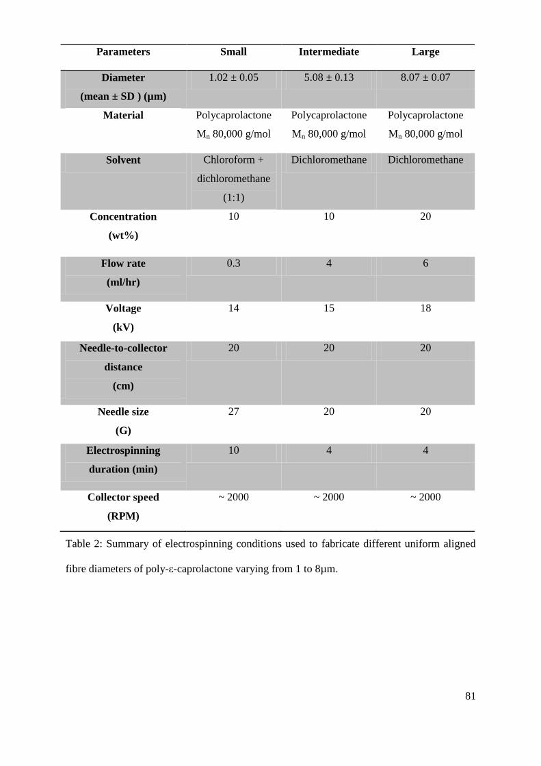
81
Parameters Small Intermediate Large
Diameter
(mean ± SD ) (µm)
1.02 ± 0.05 5.08 ± 0.13 8.07 ± 0.07
Material Polycaprolactone
Mn 80,000 g/mol
Polycaprolactone
Mn 80,000 g/mol
Polycaprolactone
Mn 80,000 g/mol
Solvent Chloroform +
dichloromethane
(1:1)
Dichloromethane Dichloromethane
Concentration
(wt%)
10 10 20
Flow rate
(ml/hr)
0.3 4 6
Voltage
(kV)
14 15 18
Needle-to-collector
distance
(cm)
20 20 20
Needle size
(G)
27 20 20
Electrospinning
duration (min)
10 4 4
Collector speed
(RPM)
~ 2000 ~ 2000 ~ 2000
Table 2: Summary of electrospinning conditions used to fabricate different uniform aligned
fibre diameters of poly-ε-caprolactone varying from 1 to 8µm.

82
Figure 9: Characterization of electrospun PCL fibres for fibre alignment, density and
diameter by SEM image analysis. (A), (B) and (C) show SEM images of PCL fibres of small,
intermediate and large diameters, respectively. Scale bar = 10 µm.
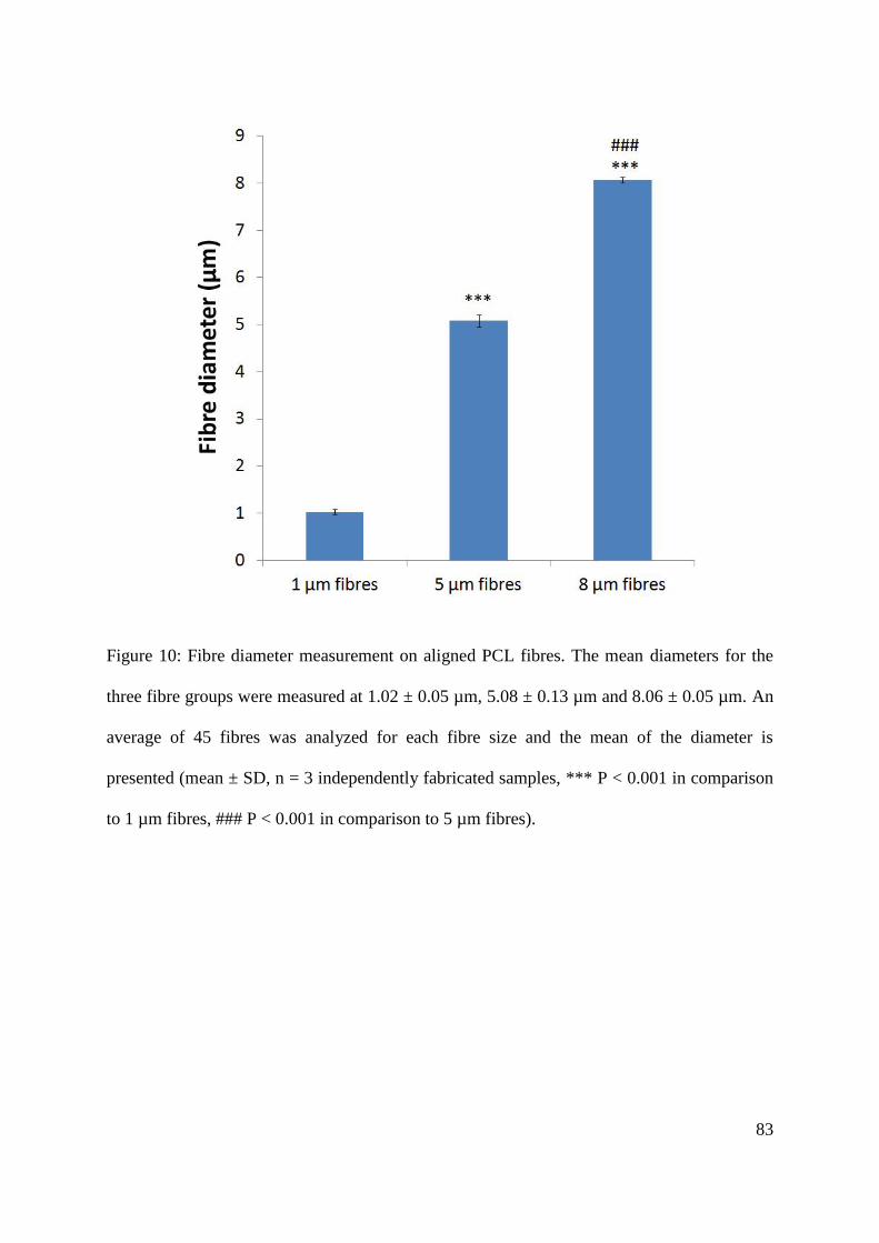
83
Figure 10: Fibre diameter measurement on aligned PCL fibres. The mean diameters for the
three fibre groups were measured at 1.02 ± 0.05 µm, 5.08 ± 0.13 µm and 8.06 ± 0.05 µm. An
average of 45 fibres was analyzed for each fibre size and the mean of the diameter is
presented (mean ± SD, n = 3 independently fabricated samples, *** P < 0.001 in comparison
to 1 µm fibres, ### P < 0.001 in comparison to 5 µm fibres).

84
Figure 11: Angular difference measurements for fibre alignment analysis on 1 µm, 5 µm and
8 µm PCL fibres. The angular difference between individual fibres and a reference line was
measured to examine fibre alignment. A centrally located fibre was chosen as the reference
line in every measurement. 38 fibres for each fibre size was analyzed and the mean frequency
were presented as mean ± SEM. (n = 3 independently fabricated samples).

85
Figure 12: Mean fibre density measurement for 1 µm, 5 µm and 8 µm aligned PCL fibres.
Small fibres (1 µm) were more densely packed than intermediate (5 µm) and large fibres (8
µm) (n = 3 independently fabricated samples, * P < 0.05 in comparison to 1 µm fibre).

86
5.2. NG108-15 neuronal cell culture on aligned PCL microfibres
5.2.1. The effect of serum on NG108-15 neuronal cell differentiation and proliferation
To determine the optimal culture medium conditions for promoting neuronal cell
differentiation, the effect of serum containing medium on neurite growth as well as neuronal
cell proliferation was studied.
Figure 13 and Figure 14 show representative live images of NG108-15 neuronal cells
grown in serum free medium (
Figure 13) and in 10% foetal calf serum (FCS) containing medium (Figure 14)
obtained by a Cell-IQ live imaging system. The images are presented at an interval of 8 hours
over 4 day culture period. Qualitative observations revealed that neuronal cells in both
conditions were actively mobile but with no obvious pattern. In the first 30 hours, in both
conditions, neuronal cells were observed to contain neurites, however, this was infrequent. It
was also observed that NG108-15 neuronal cells were constantly extending and retracting
neurites in that period. Nonetheless, after 48 hours in culture, neurite extension was becoming
more predominant in serum free medium with an increased number of neurites together with
longer neurites observed. In 10% FCS containing medium, the number of cells started
increasing within the first 24 hours. Neuronal cells were observed to contain neurites
throughout the 96 hour culture period, but they were relatively shorter than in serum free
medium.
The effect of serum on neuronal cell differentiation were quantitatively analysed for
neurite growth which was assessed by measuring the total neurite length per field-of-view
(Figure 15). The measurement was carried out over an area of 2.66 mm2. After a 90 hour
culture period, the average total neurite length per field-of-view measured in serum free
medium was 8792.09 ± 1554.68 µm, which was 98.16% longer than in 10% FCS medium

87
(4436.68 ± 835.59 µm). The overall rate of neurite growth in serum free medium (90.15 ±
17.79 µm/hour) was faster by 98.13% in comparison to in 10% FCS medium (45.5 ± 9.78
µm/hour). Interestingly, in the first 30 hours of culture, the rate of neurite growth in serum
free medium was measured at 43.76 ± 2.95 µm/hour, however, after more than 30 hours
culture, the rate increased by 159% with a rate of 113.34 ± 25.22 µm/hour. Similarly, neurite
growth rate also increased from 26.31 ± 3.79 µm per hour to 55.1 ± 13.24 µm per hour after
more than 30 hour culture in 10% FCS medium.
The effect of serum on NG108-15 neuronal cell proliferation was then studied.
NG108-15 neuronal cells cultured in either serum free medium or 10% FCS containing
medium were assessed for the percentage of area occupied by neuronal cells through live
imaging analysis (Figure 16). The measurement was conducted over an area of 2.66 mm2. Of
note was a clear difference in the proliferative behaviour of NG108-15 neuronal cells in the
presence of serum. After a 90 hour culture period, neuronal cells in 10% FCS medium
covered 42.23 ± 6.52% of measured area while, in serum free medium, only 12.63 ± 5.73%
of the measured area was occupied by neuronal cells, which was lower by 70.09% than in
serum containing medium. Over a period of 90 hours, the proliferation rate of neuronal cells
in serum containing medium was measured at 0.412 ± 0.072 % per hour, markedly higher
than in the absence of serum (0.063 ± 0.046 % per hour). The results indicated that serum had
an opposite effect with respect of NG108-15 neuronal cell differentiation and proliferation.
While serum promoted neuronal cell proliferation, it was also found to be inhibitory for
neuronal cell differentiation i.e. neurite growth. This provided a useful basis for studying
neurite growth in the subsequent studies.

88
Figure 13: Live imaging by Cell-IQ automated live imaging system of NG108-15 neuronal cells in serum free medium over a 90 hour culture
period. Images were shown at approximately 8 hour intervals from A to L. Significant neurite outgrowth was observed while cell proliferation
was low over the period. Scale bar = 140 µm

89
Figure 14: Live imaging by Cell-IQ automated live imaging system of NG108-15 neuronal cells in 10% FCS containing medium over a 90 hour
culture period. Images were shown at approximately 8 hour intervals from A to L. Increased neuronal cell proliferation was observed with less
pronounced neurite outgrowth over the period. Scale bar = 140 µm

90
Figure 15: Neurite growth analysis for studying the effect of serum on NG108-15 neuronal
cell differentiation. The measurement of the total neurite length per field-of-view was
conducted over an area of 2.66 mm2 over a 90 hour culture period. In the absence of serum,
neurite growth was markedly higher than in serum containing medium. Data was presented in
mean derived from triplicate samples.
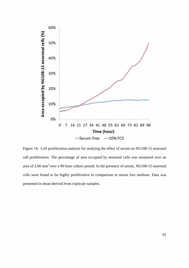
91
Figure 16: Cell proliferation analysis for studying the effect of serum on NG108-15 neuronal
cell proliferation. The percentage of area occupied by neuronal cells was measured over an
area of 2.66 mm2
over a 90 hour culture period. In the presence of serum, NG108-15 neuronal
cells were found to be highly proliferative in comparison in serum free medium. Data was
presented in mean derived from triplicate samples.
92
5.2.2. Determination of the optimal culture duration for NG108-15 neuronal cell culture on
aligned polycaprolactone (PCL) microfibres
For optimization of the method for culturing NG108-15 neuronal cells on aligned
PCL microfibres, the culture duration was studied. Neuronal cells were seeded on PCL fibres
at a density of 3 x 10⁴ per scaffold and the cultures were observed for cell confluency and
neurite formation after 48 hours and 96 hours in static culture on PCL fibres. Figure 17 shows
NG108-15 neuronal cells, fluorescently labelled for actin-filaments, on aligned PCL
microfibres after 48 hours and 96 hours culture. Qualitative observations revealed that more
neurites were formed after a 96 hour culture period whereas after 48 hours, neurite formation
was infrequent and shorter neurites were generated by neuronal cells in comparison to 96
hours. In both conditions, neurites were observed to adhere in an uniaxial direction which
was parallel with the scaffold. Neuronal cell confluency was slightly higher after 96 hours
than after 48 hours in culture, moreover, over-confluency was not observed after 96 hours
which permitted quantitative analysis on neurite growth e.g. neurite length measurement.

93
Figure 17: Confocal micrographs of NG108-15 neuronal cells on aligned PCL microfibres
after 48 hours and 96 hours in static culture. Neuronal cells were labelled for actin-filaments
by phalloidin–tetramethylrhodamine B isothiocyanate (TRITC). An increase in neurite
formation was observed after 96 hours in culture. Scale bar = 50 µm.
5.2.3. NG108-15 neuronal cells culture on aligned PCL microfibres with different fibre
diameters
The ability of aligned PCL microfibres to support neuronal cell growth was studied by
culturing NG108-15 neuronal cells on 1 µm, 5 µm and 8 µm PCL fibres for 4 days. Figure 18
shows representative confocal micrograph images of NG108-15 neuronal cells stained for β
III- tubulin after culture on small diameter (~ 1 µm; Figure 18A), intermediate diameter (~ 5
µm; Figure 18B) and large diameter fibres (~ 8 µm; Figure 18C) for four days. Figure 18 (A,
B and C) are images derived from the compression of z-stacked confocal images into single
plane images. Figure 18 (D, E and F) show three dimensional projections of z-stacked images
taken of neuronal cells on 1 µm, 5 µm, and 8 µm PCL fibres, respectively (where the z-depth
was between 90 µm and 130 µm). Figure 18 (G, H and I) show micrographs of neuronal cells

94
on flat control reference substrates comprising of a spun coated PCL film (Figure 18G),
tissue culture polystyrene (TCPS; Figure 18H) and glass (Figure 18I). Figure 18 (A, B and C)
shows that the direction of neurite outgrowth from the cell body on 1 µm, 5 µm, and 8 µm
PCL fibres corresponded to the direction of fibre alignment, where the arrows in the images
indicate the direction of fibre alignment. However, as expected on flat surface substrates,
neurite outgrowth from each adherent cell was observed to grow in a random direction
(Figure 18G, H, I). The results support the finding that PCL microfibres, irrespective of the
diameter studied, supported the initial adherence and thereafter the direction of neurite
outgrowth on 3D microfiber scaffolds under static culture and that PCL is a therefore a
permissive substrate for neuronal cell adhesion and growth.

95
Figure 18: Confocal microscopy images of NG108-15 neuronal cells immunocytochemically-
labelled for beta-III tubulin after 4 days culture in serum free medium on aligned PCL fibres
of 1 µm (A), 5 µm (B) and 8 µm (C) diameter and on flat substrates (control) comprising of
PCL film (G), glass (H) and TCPS (I). Neurite outgrowth was guided to the orientation of
aligned PCL fibres (arrows) for all fibre diameters. Neurite growth was randomly orientated
on all flat substrates. 3D composite images of neuronal cells on fibres are shown in D (1 µm),
E (5 µm) and F (8 µm). Scale bar = 50 µm.
96
5.2.4. The effect of fibre diameter on the extent of NG108-15 neuronal cell differentiation
The relationship between microfiber diameter and markers for neuronal cell
differentiation; i) maximum neurite length, ii) the number of neurites per neuron and iii) the
percentage of neurite bearing neurons was then studied. The measurements were carried out
over a z-depth between 90 µm and 130 µm. Figure 19 shows that after four days in static
culture on PCL fibre scaffolds the maximum neurite length increased with an increase in fibre
diameter. The longest neurites observed were measured on the large fibre diameter group (~ 8
µm) and had a mean length of 142.36 ± 9.68 µm. The intermediate fibre diameter group (~ 5
µm) was found to support neurite lengths of 94 ± 5.16 µm. In contrast, the small fibre
diameter group (~ 1 µm) supported a mean neurite outgrowth length of just 61.83 ± 6.89 µm.
Thus, the longest neurites were found to grow on the widest (~ 8 µm) fibres studied and were
51% longer than on the intermediate diameter fibres (~ 5 µm; P <0.05) and 130% longer than
on the small diameter fibres (P <0.001). The mean maximum neurite length observed to grow
on 5 µm diameter fibres was comparable to the length of neurites detected when neuronal
cells were cultured on a flat reference surface comprising of spin-coated PCL (108.45 ± 14.56
µm), glass (96.51 ± 3.65 µm) or TCPS (84.32 ± 7.48 µm) with no significant differences
detected here. Significant differences were detected between the mean neurite length on 1 µm
fibres versus PCL film (P <0.05) and 8 µm fibres versus glass (P <0.05) and TCPS (P <0.01).
Measurements of the number of neurites per neuronal cell arising after four days
cultured on PCL fibres revealed no significant differences between the three fibre diameter
sample groups (Figure 20). The number of neurites per neuronal cell was on average lower
when grown on PCL fibres of all diameters (in comparison with the flat reference surfaces (1
µm diameter = 1.16 ± 0.12; 5 µm diameter = 1.15 ± 0.02 and 8 µm diameter = 1.18 ± 0.02

97
neurites per neuronal cell)), as the number of neurites detected on flat surfaces measured 1.54
± 0.26 for PCL film, 1.77 ± 0.26 for TCPS and 1.52 ± 0.12 for glass. Despite that, no
significance differences were detected between the substrates.
Measurements conducted on the percentage of neurite bearing neuronal cells revealed
that 5 µm fibres supported the highest number of neuronal cells expressing neurites (40.99 ±
3.13 %) as a population, with the large fibre group supporting 31.03 ± 7.06 % and the small
fibre group supporting 20.88 ± 0.57 % (Figure 21). The difference between all fibre groups
was found not to be significant. As a reference, flat substrate surfaces as PCL film supported
54.8 ± 10.61 %, TCPS 58.83 ± 12.56 % and glass 62.77 ± 9.11 % of neurite bearing neuronal
cells. The percentage of neurite bearing neurons on glass was significantly higher than on 1
µm fibres (P < 0.05).

98
Figure 19: Maximum neurite length measurements for neurite growth analysis on aligned
PCL fibres of different diameters (1 m, 5 m and 8 µm) and on flat substrates of PCL film,
glass and TCPS. Maximum neurite length was obtained by measuring the longest neurite per
neuronal cell. An average of 34 neurites for each diameter were analyzed (mean ± SEM, n =
3 independent experiments * P < 0.05, ** P < 0.05, *** P < 0.001 in comparison to 8 µm
fibres, # P < 0.05 in comparison to 1 µm fibres). Maximum neurite lengths increased with
fibre diameter (* P < 0.05, ** P < 0.05, *** P < 0.001 in comparison to 8 µm fibres, # P <
0.05 in comparison to 1 µm fibres).

99
Figure 20: Measurement of number of neurites per neuron for neurite growth analysis on
aligned PCL fibres of different diameters (1 m, 5 m and 8 µm) and on flat substrates of
PCL film, glass and TCPS. Number of neurites per neuronal cell was measured. An average
of 34 neuronal cells for each diameter was analyzed. Number of neurites per neuronal cell
was reduced on PCL fibres in comparison to flat substrates (PCL film, glass, TCPS) but no
significant difference was detected.
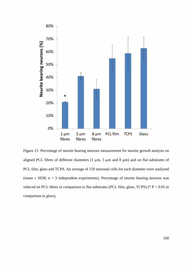
100
Figure 21: Percentage of neurite bearing neurons measurement for neurite growth analysis on
aligned PCL fibres of different diameters (1 m, 5 m and 8 µm) and on flat substrates of
PCL film, glass and TCPS. An average of 150 neuronal cells for each diameter were analyzed
(mean ± SEM, n = 3 independent experiments). Percentage of neurite bearing neurons was
reduced on PCL fibres in comparison to flat substrates (PCL film, glass, TCPS) (* P < 0.05 in
comparison to glass).
101
5.2.5. NG108-15 neuronal cell viability on aligned PCL microfibres with different fibre
diameters
The effect of fibre diameter on NG108-15 neuronal cell viability was then studied.
Figure 22 shows representative confocal micrograph images of NG108-15 neuronal cells
stained with Syto-9TM
(live cell marker) and propidium iodide (dead cell marker) after 4 day
culture on aligned PCL microfibres (1 µm (Figure 22A), 5 µm (Figure 22B) and 8 µm
(Figure 22C)) and on flat control reference substrates comprising spun coated PCL film
(Figure 22D), tissue culture polystyrene (TCPS; Figure 22H) and glass (Figure 22I). Figure
22 (A, B and C) shows images derived from the compression of z-stacked confocal images
into single plane images. Neuronal cells cultured on the three microfiber scaffold groups were
assessed for the percentage of live versus dead cells after four days in culture (Figure 23). Of
note was a clear relationship between PCL fibre diameter and the percentage of live cells.
81.82 ± 1.61% live cells were observed when grown on large diameter (8 µm) fibres, while
83.35 ± 2.69% live cells were identified on intermediate diameter (5 µm) fibres. The live
neuronal cell population decreased markedly to 64.63 ± 6.07% when grown on the small
diameter fibre group. In contrast, the percentage of live neuronal cells when cultured on flat
control surface materials were 81.76 ± 4.48% for PCL film, 87.25 ± 2.50% for TCPS and
87.70 ± 2.53% for glass. No significant differences were observed between the percentage of
live neuronal cells between 8 µm and 5 µm fibre diameter samples or with the flat reference
surfaces. However, a highly significant difference was observed between the percentage of
live cells when grown on 1 µm fibres with all other sample groups (p <0.05 in comparison to
5 µm fibres, 8 µm fibres and PCL film, p < 0.01 in comparison to TCPS and glass).

102
Figure 22: Confocal microscopy images of NG108-15 neuronal cells for live/dead analysis
after 4 days culture in serum free medium on aligned PCL fibres of 1 µm (A), 5 µm (B) and 8
µm (C) diameter versus flat substrates (control) comprising of PCL film (D), tissue culture
polystyrene (TCPS; E) and glass (F). Neuronal cell nuclei were labelled with Syto-9TM
(live
cell marker) and propidium iodide (dead cell marker) which are shown in green and red,
respectively. Scale bar = 100 µm.
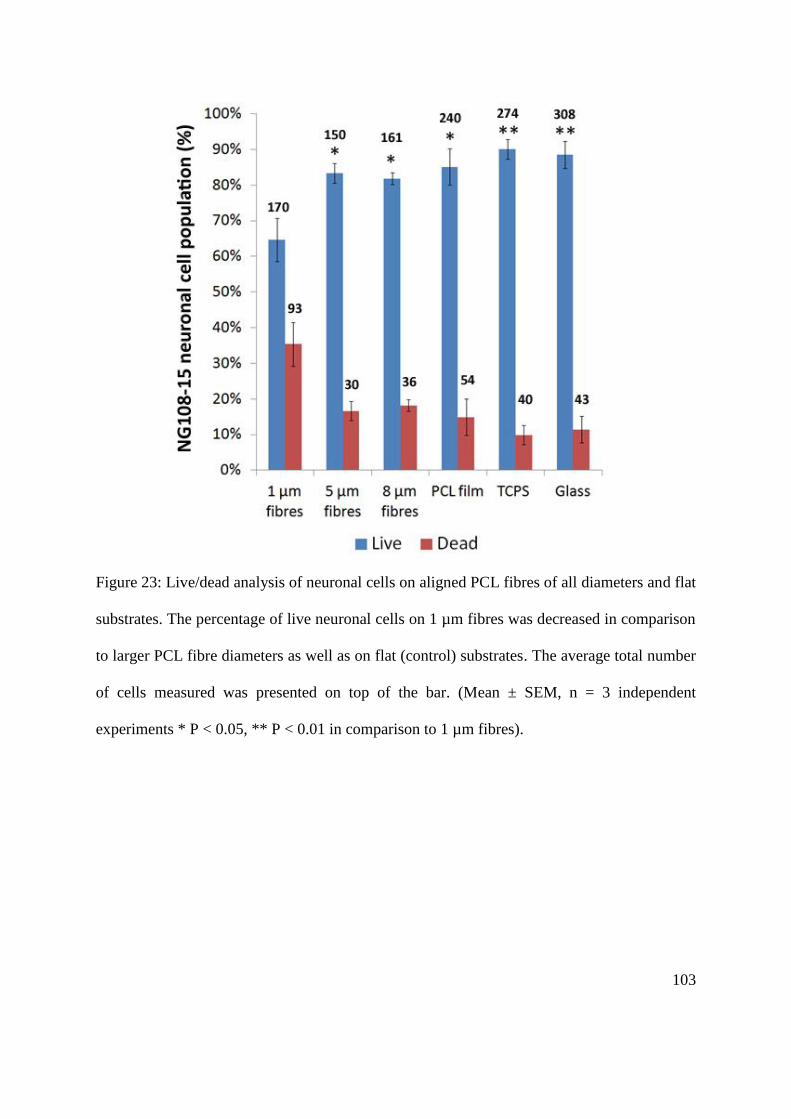
103
Figure 23: Live/dead analysis of neuronal cells on aligned PCL fibres of all diameters and flat
substrates. The percentage of live neuronal cells on 1 µm fibres was decreased in comparison
to larger PCL fibre diameters as well as on flat (control) substrates. The average total number
of cells measured was presented on top of the bar. (Mean ± SEM, n = 3 independent
experiments * P < 0.05, ** P < 0.01 in comparison to 1 µm fibres).

104
5.2.6. Quantification of the total number of NG108-15 neuronal cell per unit surface area on
aligned PCL microfibres with different fibre diameters
The relationship between NG108-15 neuronal cell number and surface area was
assessed by quantifying the total number of Syto-9TM
and propidium iodide positively-
labelled cells in an area of 1.42 mm2 after 4 days in static culture (Figure 24). The surface
area of 1 µm, 5 µm and 8 µm fibres were measured at 1.48 mm2, 3.82 mm
2 and 5.39 mm
2,
respectively while the surface area of PCL film, TCPS and glass were measured at 1.42 mm2.
The small fibre group (1 µm) was found to support the highest number of neuronal cell with
the mean total cell number per unit surface area of 213.05 ± 5.47 in comparison to the
intermediate (5 µm; 45.80 ± 10.12) and large (8 µm; 48.66 ± 12.28) fibre groups. However,
number of neuronal cell on 1 µm fibres was comparable to on PCL film which has the mean
total cell number per unit surface area of 188.33 ± 14.73. Interestingly, flat substrates (TCPS
and glass) were found to support higher number of neuronal cell than PCL fibres and PCL
film with the total neuronal cell per unit surface area on TCPS and glass were measured at
309.73 ± 51.78 and 355.26 ± 37.18, respectively. Statistically, the total neuronal cell number
per unit surface area on glass and TCPS was significantly higher than on PCL fibres with 5
µm and 8 µm diameters. There was significant difference when the total neuronal cell
number per unit surface area on glass was compared to on 1 µm fibres and PCL film.

105
Figure 24: Quantification of the total NG108-15 neuronal cell number per unit surface area
on aligned PCL fibres of all diameters and flat substrates. The quantification was conducted
on an area of 1.42 mm2 from 3 random areas on samples. The total neuronal cell number was
higher on 1 µm PCL fibres in comparison to 5 µm and 8 µm fibres. The total neuronal cell
number per area decreased on PCL fibres and PCL film in comparison to on flat substrates
(TCPS and glass). (Mean ± SEM, n = 3 independent experiments * P < 0.05, in comparison
to 1 µm fibres, + P < 0.05 in comparison to PCL film).
106
5.3. Primary Schwann cell culture on aligned PCL microfibres
5.3.1. Determination of the optimal culture duration for primary Schwann cells on aligned
polycaprolactone (PCL) microfibres
To optimize the method for culturing rat primary Schwann cells on aligned PCL
microfibres, the culture duration was studied. Schwann cells were seeded onto PCL fibres
with 1 µm, 5 µm and 8 µm fibre diameters at a density of 5 x 10⁵ cells per scaffold. Cultures
were observed for confluency after 4 days and 8 days in static culture on PCL fibres. Figure
25 shows primary Schwann cells, immunocytochemically-labelled for S100 (a Schwann cell
marker), on PCL fibres after 4 days and 8 days in culture. Qualitative observations indicated
that Schwann cell confluency on all fibres was markedly higher after being cultured for 8
days compared to 4 days. At day 4, there was evidence indicating that Schwann cells aligned
parallel to the orientation of PCL fibres. Schwann cell alignment was also observed after 8
days.
5.3.2. Primary Schwann cell culture on aligned PCL microfibres with different fibre
diameters
Schwann cell growth on aligned PCL microfibres was studied by growing rat primary
Schwann cells on 1 µm, 5 µm and 8 µm PCL fibres for 8 days. Primary Schwann cells were
stained for S100β after culture on 1 µm (Figure 26A), 5 µm (Figure 26B) and 8 µm fibres
(Figure 26C) for 8 days. Figure 26A, Figure 26B and Figure 26C show images derived from
the compression of z-stacked confocal images into single plane images. Primary Schwann
cells were also cultured on spin-coated PCL film (Figure 26G), TCPS (Figure 26H) and glass
(Figure 26I) as control reference surfaces. Figure 26A, Figure 26B and Figure 26C show that
107
cells on all fibre groups were organized parallel to the alignment of fibres (indicated by
arrows) while on flat reference surfaces, they were randomly organized as shown in Figure
26G, Figure 26H and Figure 26I. Qualitative observation revealed that primary Schwann cells
were scarcely distributed on spin-coated PCL film compared to glass and TCPS.
Interestingly, a large population of Schwann cells was detected on PCL fibres of all fibre
diameter groups in comparison to PCL film and especially on 1 µm fibres, as compared to 5
µm and 8 µm fibres. Data suggests that smaller diameter PCL fibres supported better
Schwann cell adhesion and growth. 3D confocal (z-stacked) images illustrated that primary
Schwann cells were able to adhere and grow well on all PCL fibre scaffolds (Figure 26D,
Figure 26E, Figure 26F) (z-depth = 90 to 130 µm).

108
Figure 25: Confocal images of primary Schwann cells on aligned PCL microfibres after 4
days and 8 days in static culture. Schwann cells were immunolabelled for S100β (a Schwann
cell marker). Higher confluency of Schwann cells was achieved after 8 days culture. Scale
bar = 50 µm.
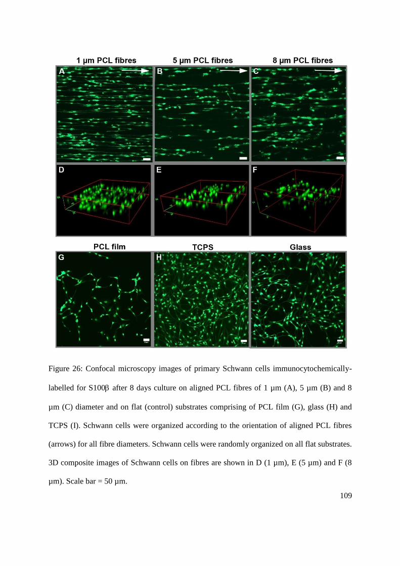
109
Figure 26: Confocal microscopy images of primary Schwann cells immunocytochemically-
labelled for S100 after 8 days culture on aligned PCL fibres of 1 µm (A), 5 µm (B) and 8
µm (C) diameter and on flat (control) substrates comprising of PCL film (G), glass (H) and
TCPS (I). Schwann cells were organized according to the orientation of aligned PCL fibres
(arrows) for all fibre diameters. Schwann cells were randomly organized on all flat substrates.
3D composite images of Schwann cells on fibres are shown in D (1 µm), E (5 µm) and F (8
µm). Scale bar = 50 µm.

110
5.3.3. The effect of fibre diameter on the phenotype of primary Schwann cells
In order to investigate the physical effect of fibre diameter on the phenotype of
primary Schwann cells, the cell length was measured as a marker of morphology (Figure 27).
The longest cells observed were measured on the narrowest fibres (1 µm; 116.53 ± 7.85 µm)
whereas cells were significantly shorter on 5 µm fibres by 31% (80.27 ± 5.45 µm, p < 0.01)
and 52% shorter (56.35 ± 5.01 µm, p < 0.001) on 8 µm fibres (in comparison to 1 µm fibres).
Importantly, the difference in Schwann cell length between 5 and 8 µm fibre was significant
(P <0.05). On the flat control surfaces, the longest Schwann cell length observed was on
TCPS (104.23 ± 3.37 µm) which was comparable to 1 µm fibres (no significance). The
shortest cell length was observed on PCL film (60.71 ± 0.79 µm) which was comparable to 8
µm fibres (no significance). The mean cell length on glass was 90.32 ± 3.37 µm. Results
therefore support a positive relationship between fibre diameter and primary Schwann cell
morphology, which interestingly was in contrast to data on neuronal cell phenotype.

111
Figure 27: Tip-to-tip Schwann cell length measurement on fibres and flat (control) substrates
for morphological assessment. Cell length decreased with an increase in the fibre diameter.
An average of 100 Schwann cells per condition was examined and results presented as mean
± SEM (n = 3 independent experiments, * P < 0.05, ** P < 0.01, *** P < 0.001 in comparison
to 8 µm fibres, ##P < 0.01, ### P < 0.001 in comparison to PCL film, + P < 0.05, ++ P < 0.01
in comparison to 5 µm fibres).

112
5.3.4. Primary Schwann cell viability on aligned PCL microfibres with different diameters
The relationship between fibre diameter and primary Schwann cell viability was then
studied. Figure 28 shows representative confocal micrograph images of primary Schwann
cells stained with Syto-9TM
, a live cell marker and propidium iodide, a dead cell marker after
8 day culture on aligned PCL microfibres (1 µm (Figure 28A), 5 µm (Figure 22B) and 8 µm
(Figure 28C)) and on flat control reference substrates comprising spin-coated PCL film
(Figure 28D), tissue culture polystyrene (TCPS; Figure 28H) and glass (Figure 28I). Figure
28 (A, B and C) shows images derived from the compression of z-stacked confocal images
into single plane images. Quantification of live and dead cells was carried out to assess
Schwann cell viability on the PCL fibres and flat reference surfaces (Figure 29). More than
99% of the cell population on all substrates was observed to comprise live cells. The
percentage of live cells on 1 µm fibres was 99.84 ± 0.03%, 99.88 ± 0.01% on 5 µm fibres and
99.91 ± 0.09% on 8 µm fibres. On flat reference surfaces, the percentage was 99.30 ± 0.22%
on PCL film, 99.88 ± 0.03% on TCPS and 99.96 ± 0.04% on glass. A small significant
difference was found on 5 µm, 8 µm fibres, TCPS and glass in comparison to 1 µm fibres.
Quantification of Schwann cell length and live/dead assay were conducted throughout the
depths of the scaffolds (between 90 to 130 µm).
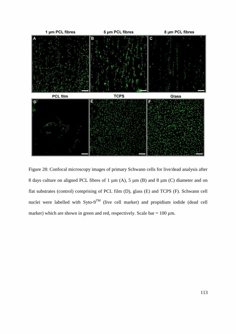
113
Figure 28: Confocal microscopy images of primary Schwann cells for live/dead analysis after
8 days culture on aligned PCL fibres of 1 µm (A), 5 µm (B) and 8 µm (C) diameter and on
flat substrates (control) comprising of PCL film (D), glass (E) and TCPS (F). Schwann cell
nuclei were labelled with Syto-9TM
(live cell marker) and propidium iodide (dead cell
marker) which are shown in green and red, respectively. Scale bar = 100 µm.

114
Figure 29: Live/dead analysis of primary Schwann cells on aligned PCL fibres of all
diameters and the flat (control) substrates. More than 99% of the cell population measured
was live cells on all PCL fibres and all flat (control) substrates. The average total number of
cells measured was presented on top of the bar. An average of 500 Schwann cells per
condition was examined and results presented as mean ± SEM (n = 3 independent
experiments * P < 0.05 in comparison to PCL film).
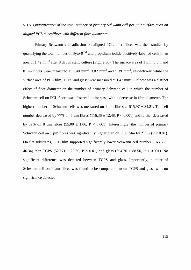
115
5.3.5. Quantification of the total number of primary Schwann cell per unit surface area on
aligned PCL microfibres with different fibre diameters
Primary Schwann cell adhesion on aligned PCL microfibres was then studied by
quantifying the total number of Syto-9TM
and propidium iodide positively-labelled cells in an
area of 1.42 mm2 after 8 day in static culture (Figure 30). The surface area of 1 µm, 5 µm and
8 µm fibres were measured at 1.48 mm2, 3.82 mm
2 and 5.39 mm
2, respectively while the
surface area of PCL film, TCPS and glass were measured at 1.42 mm2. Of note was a distinct
effect of fibre diameter on the number of primary Schwann cell in which the number of
Schwann cell on PCL fibres was observed to increase with a decrease in fibre diameter. The
highest number of Schwann cells was measured on 1 µm fibres at 515.97 ± 34.21. The cell
number decreased by 77% on 5 µm fibres (116.36 ± 12.48, P < 0.001) and further decreased
by 89% on 8 µm fibres (55.00 ± 1.06, P < 0.001). Interestingly, the number of primary
Schwann cell on 1 µm fibres was significantly higher than on PCL film by 211% (P < 0.01).
On flat substrates, PCL film supported significantly lower Schwann cell number (165.63 ±
46.34) than TCPS (529.71 ± 29.50, P < 0.01) and glass (594.76 ± 88.56, P < 0.001). No
significant difference was detected between TCPS and glass. Importantly, number of
Schwann cell on 1 µm fibres was found to be comparable to on TCPS and glass with no
significance detected.
116
Figure 30: Quantification of the total primary Schwann cell number per unit surface area on
aligned PCL fibres of all diameters and flat substrates. The quantification was conducted on
an area of 1.42 mm2 from 3 random areas on samples. On PCL fibres, Schwann cell number
increased with a decrease in the fibre diameter. (Mean ± SEM, n = 3 independent
experiments ** P < 0.01, *** P < 0.001 in comparison to 1 µm fibres, # P < 0.05, ++ P <
0.01, +++ P < 0.001 in comparison to PCL film).
117
5.4. Co-culture of neuronal and Schwann cells on aligned polycaprolactone
(PCL) microfibres
5.4.1. Determination of the optimal seeding number for NG108-15 neuronal cells for
establishing neuronal-Schwann cell co-cultures on aligned polycaprolactone (PCL)
microfibres
To determine the optimal NG108-15 neuronal cell seeding number for establishing
neuronal-Schwann cell co-cultures, neuronal cells were seeded at a density of 1000 or 7000
cells per scaffold directly on 1 µm, 5 µm and 8 µm PCL fibres pre-cultured with primary
Schwann cells. The scaffolds were pre-cultured with primary Schwann cells at a density of
500,000 cells per scaffold for 8 days before establishing the co-cultures. After 4 days, co-
cultures were qualitatively observed for neuronal cell confluency on PCL fibres to ensure a
balance between neuronal over confluence, versus observing a representative number of cells
for quantitative analysis. Figure 31 shows βIII-tubulin immunoreactive neuronal cells co-
cultured with S100β immunoreactive Schwann cells on PCL fibres. After 4 days, neuronal
cells confluency was observed to be similar between co-cultures seeded with 1000 or 7000
neuronal cells. In both conditions, high neuronal cell confluency was detected on all fibres.
Nonetheless, neurite formation was noticeable under both conditions on all fibre samples
tasted.

118
Figure 31: Confocal microscopy images of NG108-15 neuronal cells (red) and primary
Schwann cells (green) co-cultured on aligned PCL microfibres with 1 µm, 5 µm and 8 µm
fibres diameters. To establish co-cultures, neuronal cells were seeded at a density of 1000 or
7000 cells per scaffold on PCL fibres which was pre-cultured with primary Schwann cells at
a density of 500,000 cells per scaffold for 8 days. Neuronal and Schwann cells were
immunolabelled for βIII-tubulin and S100β, respectively. A high confluency of neuronal cells
was observed under both conditions for all fibres. Scale bar = 50 µm.

119
5.4.2. NG108-15 neuronal cell/primary Schwann cell co-cultures on aligned PCL microfibres
with different fibre diameters
Figure 32 shows confocal micrograph images of NG108-15 neuronal cells (red) on 1
µm (Figure 32G), 5 µm (Figure 32H) and 8 µm PCL fibres (Figure 32I) in co-culture with
primary Schwann cells (green). Figure 32 A-I are images derived from the compression of z-
stacked confocal images into single plane images. Primary Schwann cells were observed to
organize according to the direction of PCL fibre alignment (indicated by arrows) (Figure
32D, Figure 32E, Figure 32F) and a similar observation was detected for the direction of
neuronal cell neurite growth (Figure 32A, Figure 32B, Figure 32C). Qualitative observation
of single plane images (Figure 32G, Figure 32H, Figure 32I) and 3D composite images
(Figure 32J, Figure 32K, Figure 32L) indicated that NG108-15 neuronal cells and primary
Schwann cells were able to co-exist on all fibre groups. Neurite growth on 1 µm, 5 µm and 8
µm fibres in co-culture with primary Schwann cells was measured and analysis was
conducted through a z-depth of 90 µm to 130 µm (Figure 33). The mean maximum neurite
length on 1 µm fibres was 120.13 ± 6.08 µm, which was comparable to the mean length on 5
µm fibres (139.43 ± 6.81 µm) and 8 µm fibres (134.11 ± 9.42 µm) with no significant
difference detected between the groups. Interestingly, NG108-15 neuronal cells on 1 µm
fibres produced significantly longer neurites in the presence of Schwann cells (120.13 ± 6.08
µm) versus the absence of Schwann cells (61.83 ± 8.81 µm) (P <0.01). Similarly, an
increased neurite length was also detected on 5 µm fibres (139.43 ± 6.81 µm in the presence
of Schwann cells versus 94.00 ± 5.16 µm in the absence of Schwann cells (P <0.05)). No
significant difference in neurite length was detected between neuronal cells grown alone on 8
µm fibres versus neuronal cells plus Schwann cells.
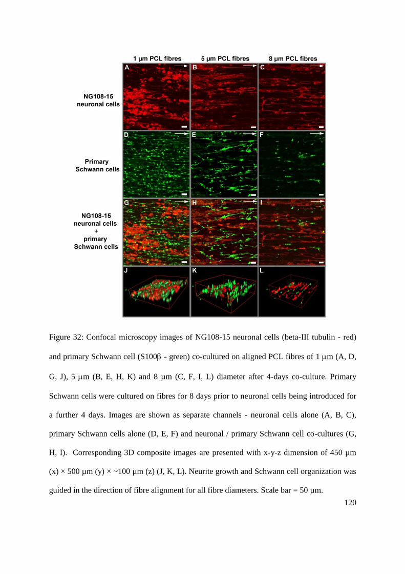
120
Figure 32: Confocal microscopy images of NG108-15 neuronal cells (beta-III tubulin - red)
and primary Schwann cell (S100 - green) co-cultured on aligned PCL fibres of 1 m (A, D,
G, J), 5 m (B, E, H, K) and 8 µm (C, F, I, L) diameter after 4-days co-culture. Primary
Schwann cells were cultured on fibres for 8 days prior to neuronal cells being introduced for
a further 4 days. Images are shown as separate channels - neuronal cells alone (A, B, C),
primary Schwann cells alone (D, E, F) and neuronal / primary Schwann cell co-cultures (G,
H, I). Corresponding 3D composite images are presented with x-y-z dimension of 450 µm
(x) × 500 µm (y) × ~100 µm (z) (J, K, L). Neurite growth and Schwann cell organization was
guided in the direction of fibre alignment for all fibre diameters. Scale bar = 50 µm.

121
Figure 33: Maximum neurite length measurements of NG108-15 neuronal cells in co-culture
with primary Schwann cells on aligned PCL fibres of 1 m, 5 m and 8 µm. An average of
40 neuronal cells for each fibre diameter was examined (n = 3 independent experiments, **P
< 0.01, * P < 0.05 versus neuronal cells alone).

122
5.4.3. Neuronal-Schwann cell co-cultures derived from dorsal root ganglion (DRG) explants
on aligned PCL microfibres with different fibre diameters1.
To establish primary neuronal/Schwann cell co-cultures on three-dimensional PCL
fibres, adult rat DRGs were cultured on 1 µm, 5 µm and 8 µm aligned PCL fibres for 10
days. PCL fibres were examined immunohistochemically to determine axon outgrowth and
Schwann cell migration. The parallel alignment of fibres was observed to enable the
development of axons and the migration of Schwann cells from the DRG body. ß-III tubulin
immunoreactive axons readily followed the fibre structures in a highly oriented longitudinal
manner (Figure 35A-L). Interestingly, axons on the fibres were always accompanied by and
never grew beyond S100ß labelled Schwann cells (Figure 35). Indeed, a leading edge of
Schwann cells was observed to migrate along the fibres, followed closely by the axons. ß-III
tubulin immunoreactive axons were quantified in respect to axon length.
Overall, micrograph analysis of different PCL fibre conditions revealed longitudinally
oriented outgrowth of single axons. 1 µm diameter fibres supported an average axon
outgrowth from the DRG cell body of 2.5 mm, 5 µm fibres supported an average axon
outgrowth of 2.2 mm, and 8 µm fibres supported an average axon outgrowth of 1.6 mm after
10 days from the DRG body (Figure 34). Thus, smaller fibre diameters were able to support
longer neurite outgrowth. The migration of Schwann cells on aligned PCL fibres was
assessed by measuring the migration of S100β immunoreactive Schwann cells. Typically,
Schwann cells exhibited a characteristic spindle-like morphology with bipolar processes on
the fibres. 3D scaffolds with 1 µm fibre diameter supported an average Schwann cell
1 This work was conducted in collaboration with Dr Kiran Pawar (Kroto Research Institute, University of
Sheffield)

123
migration of 2.7 mm, 5 µm fibre diameter scaffolds supported an average Schwann cell
migration of 2.4 mm, and 8 µm fibre diameter scaffolds supported an average Schwann cell
migration of 1.9 mm from the DRG body (Figure 34).
Intercellular contact between axonal and Schwann cell membrane is of important for
the initiation and regulation of Schwann cell myelination [95, 97, 307]. Confocal microscopy
revealed that the overlapping regions of βIII-tubulin-immunoreactive axons (red) and S100β-
immunoreactive Schwann cells (green) arising yellow regions were observed on aligned PCL
microfibres (Figure 35D, H, L). These yellow regions indicate the co-localization of axons
and Schwann cells, suggesting that physical contacts between axons and Schwann cells were
established after 10 days in culture on PCL fibres. Importantly, the occurrence was observed
across all fibre diameters. Thus, results showed that aligned PCL microfibres supported the
formation of physical contacts between axons and Schwann cell, which may potentially
facilitate myelin formation.

124
Figure 34: Quantification of average neurite length and Schwann cell migration on 1 µm, 5
µm and 8 µm PCL microfibres from DRG culture. No significant difference was detected in
neurite length and Schwann cell migration between fibre groups (although the distance of
which Schwann cells migrated after 10 day culture was further than neurite extension on all
fibres).

125
Figure 35: Confocal microscopy images of isolated DRGs grown on 1 m (A-D), 5m (E-H) and 8m (I-L) aligned PCL fibres for 10 days.
Fibre direction is from left to right in all micrographs (A-L). (A, E, I) S100 expressing Schwann cells (green); (B, F, J) -III tubulin expressing
neurites (red) and (C, G, K) overlaid images showing co-localisation of -III tubulin expressing neurites and S100 expressing Schwann cells.
(D, H, L) shows high magnification selected regions of interest identifying close physical association of Schwann cells and neurites (yellow).
Arrows for (A, E, I) indicate the furthest identified position of migratory Schwann cells. Arrows for (B, F, J) indicate the furthest position of
neurite extension. Asterisks (*) mark the position on the left of each micrograph of where ganglion bodies were placed for culture. Scale bar =
100 m. Quantification of neurite length and Schwann cell migration on each of the fibre scaffolds.
126
5.5. Study of Schwann cell myelination on aligned polycaprolactone (PCL)
microfibres
5.5.1. Myelination of neuronal – Schwann cell co-cultures derived from dorsal root ganglion
(DRG) explants.
In this study, DRGs were explanted onto either laminin-coated tissue culture
polystyrene plate (TCPS) or aligned PCL microfibres to establish neuronal-Schwann cell co-
cultures for myelination study. Co-cultures were maintained under two culture medium
compositions; 1) DMEM with D-valine containing forskolin and 2) standard DMEM to
determine optimal culture medium for myelination. D-valine containing DMEM together
with forskolin has been shown to selectively inhibit fibroblast growth [306]. In both
conditions, co-cultures were treated with ascorbic acid to induce Schwann cell myelination
for 14 days [308]. Co-cultures were analysed for myelin expression through immunodetection
of myelin protein zero (P0) and myelin basic protein (MBP). On laminin-coated TCPS,
results revealed that negative myelin expression was detected in both culture media as shown
in Figure 36A and Figure 36B. Similarly, on aligned fibres, expression of P0 and MBP also
was not detected in both conditions (Figure 37A, Figure 37B).
Co-cultures were then immunolabelled for neuronal (βIII-tubulin) and Schwann cell
(S100β) specific markers to examine the physical interactions between axons and Schwann
cells which is known to be of important in myelination process [309]. Figure 36 (C, D) show
the presence of yellow regions, arising from the overlapping of βIII-tubulin-immunoreactive
axons (red) and S100β-immunoreactive Schwann cells (green). These indicate that co-
localization of axons and Schwann cells was observed in DRG co-cultures on laminin-coated
127
TCPS, following a 2 week treatment with ascorbic acid, thus confirming intercellular contact
between axons and Schwann cells. The yellow regions were also observed when DRG co-
cultures were grown on aligned PCL microfibres (1 µm fibre diameter), indicating the co-
localization of axons and Schwann cells on PCL fibres (Figure 37 (C, D). 3D high
magnification images illustrate that axons (red) grew directly on Schwann cells in both
media, confirming physical contacts between axons and Schwann cells on PCL fibres (Figure
37E, F). Importantly, standard DMEM and DMEM D-valine (plus forskolin) were both found
to support axonal-Schwann cell intercellular contacts in DRG co-cultures, with observable
co-localization of axons and Schwann cells on both laminin-coated TCPS and PCL fibres.
Results also showed the presence of non-S100β/ βIII-tubulin immunoreactive cells in DRG
co-cultures in both DMEM D-valine (plus forskolin) and standard DMEM (Figure 36C,
Figure 36D), suggesting the presence of fibroblasts in co-cultures.

128
Figure 36: Neuronal – Schwann cell co-cultures derived from DRG explants on laminin-
coated TCPS after a 2 week treatment with ascorbic acid. Co-cultures were maintained in
either DMEM D-valine containing forskolin (FSK) or standard DMEM. (A, B) Co-cultures
were immunolabelled for myelin protein zero and myelin basic protein for detection of
myelin expression. No positive myelin expression was detected under either condition (A, B).
Co-cultures were immunolabelled for βIII-tubulin (neuronal cell marker) and S100β
(Schwann cell marker). Physical contact between axons and Schwann cells were observed in
both media (arrows) as indicated by the yellow regions of axon-Schwann cell co-localization
(C, D). Fibroblasts (non-S100β/ βIII-tubulin immunoreactive cells) were also detected in co-
cultures. DAPI stained nuclei are presented in blue. Scale bar = 100 µm.

129
Figure 37: Neuronal – Schwann cell co-cultures derived from DRG explants on aligned PCL
microfibres (fibre diameter = 1 µm) after a 2 week treatment with ascorbic acid. Co-cultures
were maintained in either DMEM D-valine containing forskolin (FSK) or standard DMEM.
Co-cultures were immunolabelled for myelin protein zero (green) and myelin basic protein
(red) for detection of myelin expression (scale bar = 100 µm) (A, B). No positive myelin
expression was detected under either condition. Co-cultures were immunolabelled for βIII-
tubulin (green; neuronal cell marker) and S100β (red; Schwann cell marker). Physical
contacts between axons and Schwann cells were observed in both media as indicated by the
yellow regions of axon-Schwann cell co-localization (C, D). Co-cultures were presented in
3D composite images showing direct contact between axons and Schwann cells (E, F) (scale
bar = 5 µm). DAPI stained nuclei are presented in blue.
130
5.5.2. Myelination of neuronal – Schwann cell co-cultures derived from dissociated dorsal
root ganglion (DRG).
In this study, neuronal – Schwann cell co-cultures were established by growing
neuronal cells from dissociated DRGs with pre-cultured primary Schwann cells on laminin –
coated tissue culture polystyrene plate (TCPS). Co-cultures were maintained under four
culture medium compositions; 1) DMEM D-valine (plus forskolin) containing 10% foetal
calf serum (FCS), 2) serum free DMEM D-valine (plus forskolin), 3) standard DMEM
containing 10% FCS and 4) serum free standard DMEM to determine optimal culture
medium for myelination. In all conditions, co-cultures were treated with ascorbic acid to
induce Schwann cell myelination for 14 days [308]. Figure 38 shows co-cultures of βIII-
tubulin-immunoreactive neuronal cells (red) and S100β – immunoreactive Schwann cells
(green) in different culture media. Neuronal/primary Schwann cell adhesion and growth were
evident in 10% FCS DMEM D-valine (plus forskolin) and serum free standard DMEM
(Figure 38A, D), with a wide-spread distribution of neuronal and Schwann cells was
observed, whereas in serum free DMEM D-valine (plus forskolin) and 10% FCS standard
DMEM, primary Schwann cells were scarce and no neuronal cells were observed (Figure
38B, C). Of note was that the population of neuronal/Schwann cells and axon outgrowth in
10% FCS DMEM D-valine were more extensive than in serum free standard DMEM. Most
Schwann cells were found to concentrate at the vicinity of neuronal cells and their axons in
serum free standard DMEM. Presence of fibroblasts was also observed in standard DMEM
(with or without serum) as indicated by non - βIII-tubulin/S100β immunoreactive cells
(yellow arrows) in Figure 38 (C, D) but none was observed in DMEM D-valine (with or
without serum).

131
Co-cultures in 10% FCS DMEM D-valine and serum free standard DMEM were then
analysed for myelin expression through immunodetection of myelin protein zero (P0) and
myelin basic protein (MBP). Figure 39(A, C) show negative expression of myelin protein
zero (P0) and myelin basic protein (MBP) in both 10% FCS DMEM D-valine (A) and serum
free standard DMEM (B), indicating that there was no myelin formation in the co-cultures.
The importance of intercellular contacts between axons and Schwann cells in myelination has
been discussed in previous section (3.5.1). Therefore, co-cultures in both medium were
examined for the co-localization of axons and Schwann cells. Axons (red) were found to
coincide with Schwann cells in both medium, resulting in the formation of yellow regions
(arrows) shown in figure (A, B). This co-localization indicated that Schwann cells were able
to establish contact with axons in co-culture derived from dissociated DRG, following a 2
week treatment with ascorbic acid.
Myelin formation in neuronal - Schwann cell co-cultures were further studied by
detecting lipid content of the myelin sheath using Sudan Black B staining technique. In this
study, co-cultures were established by growing neuronal cells from dissociated DRGs with
pre-cultured primary Schwann cells on glass. To investigate the optimal culture medium for
myelination, co-cultures were maintained in two culture medium compositions; 1) DMEM D-
valine (plus forskolin) containing 10% foetal calf serum (FCS) and 2) serum free standard
DMEM. In both conditions, co-cultures were treated with ascorbic acid to induce Schwann
cell myelination for 14 days [308]. A clear difference was observed with respect of lipid
staining between DMEM D-valine (with 10% foetal calf serum) and serum free standard
DMEM. In serum free standard medium, dark lipid staining was observed in co-cultures
which was concentrated at the neuronal cell body and axons (Figure 39D). This may indicate
that there was possible myelin formation when neuronal-Schwann cell co-cultures were
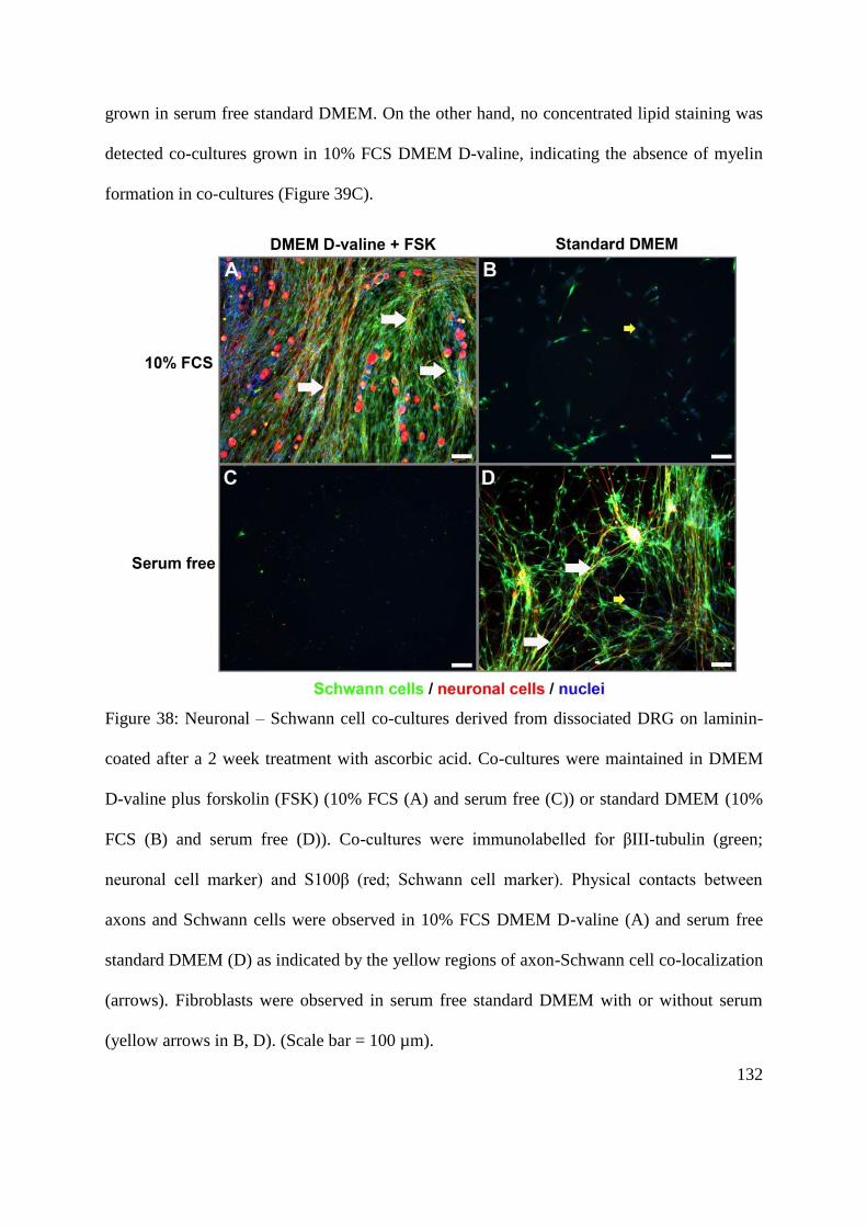
132
grown in serum free standard DMEM. On the other hand, no concentrated lipid staining was
detected co-cultures grown in 10% FCS DMEM D-valine, indicating the absence of myelin
formation in co-cultures (Figure 39C).
Figure 38: Neuronal – Schwann cell co-cultures derived from dissociated DRG on laminin-
coated after a 2 week treatment with ascorbic acid. Co-cultures were maintained in DMEM
D-valine plus forskolin (FSK) (10% FCS (A) and serum free (C)) or standard DMEM (10%
FCS (B) and serum free (D)). Co-cultures were immunolabelled for βIII-tubulin (green;
neuronal cell marker) and S100β (red; Schwann cell marker). Physical contacts between
axons and Schwann cells were observed in 10% FCS DMEM D-valine (A) and serum free
standard DMEM (D) as indicated by the yellow regions of axon-Schwann cell co-localization
(arrows). Fibroblasts were observed in serum free standard DMEM with or without serum
(yellow arrows in B, D). (Scale bar = 100 µm).
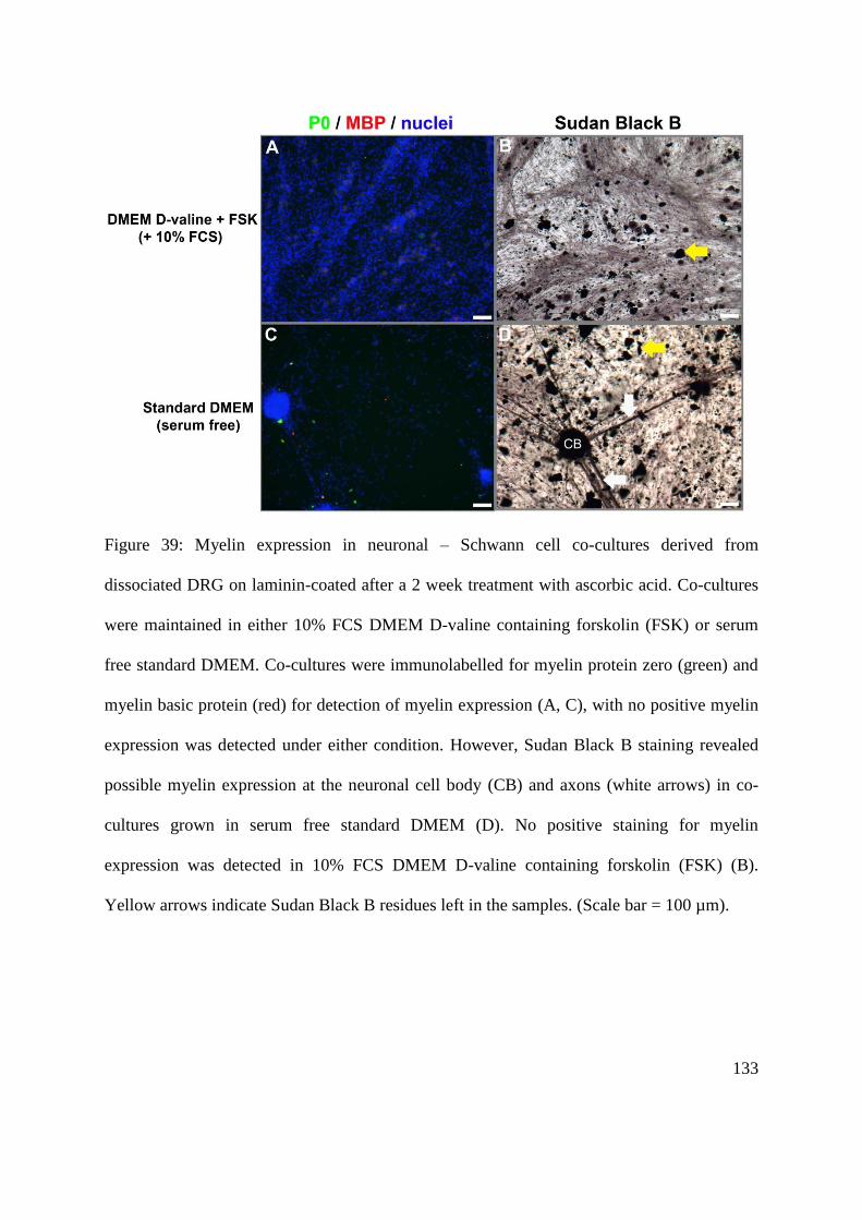
133
Figure 39: Myelin expression in neuronal – Schwann cell co-cultures derived from
dissociated DRG on laminin-coated after a 2 week treatment with ascorbic acid. Co-cultures
were maintained in either 10% FCS DMEM D-valine containing forskolin (FSK) or serum
free standard DMEM. Co-cultures were immunolabelled for myelin protein zero (green) and
myelin basic protein (red) for detection of myelin expression (A, C), with no positive myelin
expression was detected under either condition. However, Sudan Black B staining revealed
possible myelin expression at the neuronal cell body (CB) and axons (white arrows) in co-
cultures grown in serum free standard DMEM (D). No positive staining for myelin
expression was detected in 10% FCS DMEM D-valine containing forskolin (FSK) (B).
Yellow arrows indicate Sudan Black B residues left in the samples. (Scale bar = 100 µm).

134
5.5.3. Myelination of neuronal – Schwann cell co-cultures derived from dissociated dorsal
root ganglion (DRG) on aligned PCL microfibres.
Based on previous results in section 5.5.2. Myelination of neuronal – Schwann cell
co-cultures derived from dissociated dorsal root ganglion (DRG)., neuronal-Schwann cell co-
cultures were grown on aligned PCL microfibres (diameter = ~1 µm) in serum free standard
DMEM for examining myelin formation by transmission electron microscopy. Rat sciatic
nerve sections were used as a reference sample for examining the myelin sheath
ultrastructure. Figure 40 (A, C) show the lamellar structure of the myelin sheath, which
covers the outer surface of axons in sciatic nerve tissue. The higher magnification micrograph
in Figure 40C shows that the myelin sheath consists of alternating layers of the major dense
line (Schwann cell membrane layer) and the intraperiod line (Schwann cell cytoplasmic
layer). Electron micrographs of neuronal-Schwann cell co-cultures revealed that the lamellar
structure of the myelin sheath was not detected in the co-cultures (Figure 40B, D). The
fibrous feature of the scaffolds in the samples was observed to be infrequent throughout the
samples and was only found at the vicinity of cells. This observation could occur because
PCL fibres melted during embedding process at 60ºC (which is the melting point for PCL). It
is important to note that the study was only conducted once due to the time constraint of the
project. Therefore, the culture method and sample processing method for TEM analysis
require further refinements.

135
Figure 40: Transmission electron micrographs of transverse section of rat sciatic nerve (A, C)
and neuronal-Schwann cell co-cultures on aligned PCL microfibres (diameter = ~1 µm) (B,
D). Rat sciatic nerve sections were used as reference for illustrating the myelin sheath
ultrastructure which shows the alternating layers of the major dense lines (white arrow) and
the intraperiod lines (black arrow). No observation of the myelin sheath was detected in
neuronal-Schwann cell co-cultures on the scaffolds (B, D). (My) the myelin sheath. (Ax)
axons. (M) Schwann cell mitochondrion (F) fibres. Arrow in B indicates the imperfections
generated during sectioning the samples. Scale bar in A = 2 µm, scale bar in C = 200 nm,
scale bar in B, D = 5 µm.
136
6. Discussion
The study reports on the development of an in vitro three-dimensional peripheral
nerve model using aligned microfibre scaffold for supporting and organizing neuronal and
Schwann cells either individually or together as neuronal-glial co-cultures. The study also
attempted to develop a matured 3D peripheral nerve culture model by demonstrating in vitro
myelination on such scaffolds, following long term co-cultures of neuronal/Schwann cells
either from isolated dorsal root ganglion or dissociated cells. Polycaprolactone was used for
producing a range of aligned fibre diameters by electrospinning and we examined the
relationship between fibre diameter and the response of neuronal cells, Schwann cells and
neuronal-Schwann co-cultures to determine the optimal physical parameters for cellular
organisation relevant to peripheral nerve biology.
Three dimensional cell culture models can provide cellular microenvironments that
closely resemble the native environment, which can be beneficial for biological research in
areas such as trauma, disease or drug studies (reviewed in [310]). Such models are seeing a
rapid rate of development, driven by the need for conducting studies in environments which
are arguably more relevant to those which utilise cells when grown two dimensions and
typically using a single cell type in isolation. Additional motivation includes consideration of
the 3Rs (Replacement, Refinement and Reduction) in regards to animal usage and scientific
experimentation. Significant advances have been made recently in a number of 3D in vitro
models (e.g. skin [311]) which are used routinely for experimentation [312], however even
for these models the lack of a vasculature or immune system is a future challenge. In contrast,
few 3D in vitro models have been developed for peripheral nerve, but potential value and
demand exists for such models in areas including developmental biology (at the neuronal-

137
glial interface), establishing models of disease (e.g. peripheral neuropathies such as Charcot-
Marie-Tooth disease or Guillaine-Barré syndrome) and the design of scaffolds for the
development of devices to assist repair following injury and trauma. A small number of
investigators have described co-culture models for peripheral nerve using naturally-derived
materials such as collagen and fibrin [218, 313] and the application of electrospun fibres for
in vitro culture [2, 314], but few have studied in detail the physical relationship between the
scaffold, neural differentiation and neuronal/glial organisation in relation to peripheral nerve
structure. Moreover, previous studies on electrospun fibres have predominantly focussed on
developing scaffolds for nerve repair applications [26,32,33] and typically use a single cell
type [27,32,33].
6.1 Fabrication of aligned microfibres scaffold by electrospinning for in vitro
3D peripheral nerve model
The importance of the alignment of fibrous scaffolds for supporting directed growth
of neuronal and Schwann cells, has been discussed many times in both in vitro and in vivo
studies [153, 315, 316]. Besides that, the organized cellular growth generated by a 3D culture
model may provide a practical advantage in which it enables convenience and effective
analytical processes. To develop an aligned 3D culture model for peripheral nerve, the study
describes electrospinning methods for fabricating aligned microfibres scaffolds from
polycaprolactone by employing a high speed rotating collector. The use of rotating collector
with high rotational speeds (usually more than 1000 rpm) to generate aligned electrospun
fibres is commonplace [2, 225, 305]. The study also emphasizes on the optimal polymer
molecular weight and the polymer solution for successful generation of aligned fibre
scaffolds, which in this case, it was found that the best conditions were PCL with molecular
138
weight of Mn 80,000 g/mol in solution concentration ranging from 10% to 20%. Polymer
molecular weight and solution concentration are correlated to the rheological properties of
polymer solution which in turn, has influence on the jet formation and stability during
electrospinning as well as the resulting fibre formed [317].
Both micro- and nano-size electrospun fibres have been studied for their efficacy as
scaffolds for peripheral nerve studies. Wang et al. revealed that electrospun nanofibres with
diameter smaller than 0.8 µm become inhibitory to the guidance and growth of axon
extension from embryonic chick dorsal root ganglia [2] while similar observations were
reported when fibre diameter larger than 30 µm [318]. Together, these studies indicate that
there is a limited range of fibre diameter of which it becomes supportive for neurite extension
and Schwann cells growth This prompts the study to explore the potential of electrospun
microfibres at subcellular size in supporting neurite outgrowth and Schwann cell growth. The
study reports the fabrication of aligned electrospun microfibres with fibre diameter ranging
from 1 to 8 µm through careful manipulation of the electrospinning parameters. Of note was
the set of parameters used in the study enabled the generation of highly aligned fibres with
tightly controlled and reproducible fibre diameters. Manipulation of the parameters such as
applied voltage, solution concentration, flow rate and needle gauge is a commonly used
electrospinning method for controlling fibre diameter [256, 268, 305].
139
6.2 The effect of fibre diameter of aligned PCL microfibre scaffolds on
neurite outgrowth
It is evident that fibre diameter can influence cell function and behaviour including
cellular morphology, proliferation and migration [14, 251, 252, 268, 319]. However, debate
continues on whether nanofibres versus microfibers can provide the best outcome for
peripheral nerve studies (though certainly not restricted to peripheral nerve), with
investigators suggesting that nanofibres are optimal because of the close physical
resemblance to the extracellular matrix structure [226, 314]. However, reports also include
findings that 200 nm fibres are inhibitory to neurite outgrowth and Schwann cell migration
[2], and conversely that neurite growth and Schwann cell migration are inhibited on
microfibres with diameters greater than 30 µm [318]. Furthermore, in an in vitro study using
PC12 neuronal cells in isolation, no significant differences in neurite outgrowth on PCL
fibres scaffolds with diameters ranging from 0.8 µm and to 8.8 µm were observed [225]. A
recent study reports the advantage of micro-size piezoelectric fibres (~3 µm) in supporting
neurite outgrowth over nanofibres (~750 nm), with enhanced neurite elongation and
directionality of neurite growth on microfibres [316].
The study therefore investigated the relationship between PCL microfibre diameters
and neuronal cell growth in detail, using three different cell cultures approaches i.e. single
neuronal cell culture, neuronal/Schwann co-culture and DRG explants culture. Results
revealed that aligned PCL microfibres were able to both support neuronal cell growth and
direct the organized growth of neurite extension, irrespective of fibre diameters. These
observations were consistent across different culture models used in the study. However,
aligned PCL microfibres were found to reduce neurite sprouting of NG108-15 neuronal cells
140
in single culture experiments. The overall number of NG108-15 neuronal cell on PCL
substrates, both fibres and films was also found to be poor in comparison to TCPS and glass.
In single culture of NG108-15 neuronal cells, the results showed a direct correlation
between fibre diameter and the length of neurite outgrowth, with neuronal cell neurite
extension increased with increasing fibre diameter but different observations were produced
when in co-cultures. Reduced neurite elongation on smaller PCL fibres (1 µm) may be
attributed to low cell viability which was found to be lower than larger fibres. On the
contrary, smaller PCL microfibres promoted longer neurite extension in the presence of
Schwann cells in DRG scaffold cultures, although the difference was not statistically
significant. Of note was the ability of all scaffolds to support considerably long neurite
extension, which grew in average between 1.75 mm and 2.50 mm after 10-day culture. In
comparison to the typically quoted value for the rate of axonal outgrowth (1 mm/day) [320],
the rate of axonal outgrowth in DRG scaffold cultures was measured at a rate of
approximately 0.2 mm/day over a 10 day period which was lower. Nonetheless, as an in vitro
3D culture model, the scaffolds supported sufficient axonal outgrowth and Schwann cell
migration within a reasonable timeframe, enabling quantitative and qualitative analysis to be
conducted on such model. Of note was that there was no significant difference in the extent
of neuronal cell neurite extension across different fibre diameters in neuronal/Schwann cell
co-culture.
The relationship between fibre diameter and neuronal and glial cells in co-culture
revealed that Schwann cells could significantly enhance neuronal cell neurite extension. This
effect was observed on the smaller diameter fibres, with 100% and 52% increases in neurite
length for 1 µm and 5 µm scaffolds, respectively. This was most likely due to the excretion of

141
a combination of neurotrophic factors (e.g. NGF and BDNF) and the production of
extracellular matrix proteins by the Schwann cells [167, 321] which influenced neurite
outgrowth through a paracrine pathway. No significant difference in neurite length was
observed on 8 µm fibres, as the longest neurites were observed for both neuronal cells alone
and under co-culture conditions. The ability of Schwann cells to enhance neurite length has
been reported previously in vivo [322, 323] which is consistent with the present study.
6.3 The effect of fibre diameter of aligned PCL microfibres on Schwann cells
phenotype
The relationship between fibre diameter and Schwann cell behaviour, in term of
cellular growth, morphology and migration behaviours was also studied in detail. Schwann
cell culture alone demonstrated the ability of aligned PCL microfibres to support Schwann
cell growth with high cell viability without the need of surface modification to enhance cell
adhesion. Schwann cells were found to form unidirectional organization on the scaffolds,
resembling Schwann cells organization in bands of Büngner which form during regeneration
process in peripheral nerve tissue [324] and consequently, provide guidance for regenerating
axons [325]. Unidirectional alignment of Schwann cells was shown to up-regulate the
expression of myelin-specific gene and the secretion of neurotrophic factors [226, 326]. Of
note was that the consistent observations with respect of Schwann cell viability and
alignment across different fibre diameters, thus indicating the potential use of the scaffolds
for nerve repair applications.
In the study, it was found that fibre diameter influenced Schwann cell morphology
with smaller PCL fibre (1 µm) promoted more elongated bipolar morphology. Interestingly,
elongation of Schwann cell morphology has importance during the early stage of myelination

142
in vivo [309, 327], which correlates with present observations on the smaller fibre diameter
scaffolds and of relevance to both mature nerve models and neural repair approaches. Of note
was the influence of fibre diameter on Schwann cell number, with higher number of Schwann
cell observed on smaller fibre. Previously, it has been shown that aligned nanofibres (fibre
diameter ~800 nm) enhanced fibronectin adsorption in comparison to smooth film which in
turn, was implicated for the enhancement of Schwann migration and neurite outgrowth [328].
Therefore, it is speculated that the differential Schwann cell adhesion observed on aligned
PCL microfibres may be attributed to the extent of protein adsorption on different fibre
diameters.
Aligned PCL microfibres were also found to support and direct Schwann cell
migration in DRG scaffolds cultures. Schwann cell migration was also found to be affected
by fibre diameter with a slight enhancement in the migration of Schwann cells with
decreasing fibre diameter, although the difference was not statistically significant. Of
particular note was the distance of which Schwann cells travel on all scaffolds, which after 10
days in culture averaged between 1.9 mm and 2.7 mm from the DRG body. It was also
observed that Schwann cells formed a „leading‟ migratory edge ahead of the neurites, which
followed closely behind. Therefore, it is hypothesised that a permissive environment for
neurite formation was being formed during this process by the leading Schwann cells, as
either a prerequisite or an enabling condition for organising neurite development thereafter.
143
6.4 Neuronal-Schwann cell interactions on aligned PCL microfibres with
different fibre diameters
It has previously been described that myelination is mediated through the binding of
neurite membrane proteins, such as neuregulin 1 type III (NRG1-III) and nectin-like protein 1
(Necl-1) to their receptors on the Schwann cell membrane [95, 98]. The interactions between
NRG1-III and Erb B receptors initiate myelination as well as regulate the extent of
myelination in peripheral nerve [95, 307]. Interactions of cell adhesion molecules between
neurite and Schwann cells is also important [97, 98], for instance the binding of Necl-1 and
Schwann-bound Necl-4 facilitates the stabilization of intermembrane junction and the
reorganization of actin cytoskeleton during myelination [100]. Therefore, physical contact
between neurites and Schwann cells is a pre-requisite for the development of the myelin
sheath in peripheral nerve. In this regard, neurites and Schwann cells were observed to be in
regular physical contact in DRG scaffold cultures as evident by the co-localization of S100β
labelled cells and β-III tubulin labelled neurites. These observations indicated that aligned
PCL microfibres may potentially support the subsequent myelination process which is of
importance to the development of a mature peripheral nerve model. On the contrary, neurite-
Schwann cell contact was observed less frequently in NG108-15 neuronal and primary
Schwann cell co-cultures, hence making this culture approach less favourable for creating in
vitro nerve model with myelinated neurite. Of note was the abundance of NG108-15 neuronal
cells in the co-cultures, indicating increased proliferation potentially due to growth factors
release by primary Schwann cells [78].
144
6.5 The development of myelin sheath on aligned PCL microfibres
The ability of aligned PCL microfibres to support in vitro myelination was then
studied in attempt to demonstrate a mature peripheral nerve model. To establish in vitro
myelination, DRG scaffolds cultures were treated with ascorbic acid to induce myelination in
long-term cultures (2 weeks). Ascorbic acid treatment is commonplace for establishing in
vitro Schwann cell myelination since ascorbic acid is associated with the regulation of basal
lamina assembly, which in turn enabling Schwann cell myelin formation [329]. Moreover,
extended culture duration (more than 1 week) is required for complete myelin formation in
cultures [308, 330]. Other medium components used in this study include nerve growth factor
(NGF) and progesterone (one of the components in N2 supplement) which have been shown
previously to stimulate myelin expression [44, 86, 331]. Following two week culture with
ascorbic acid treatment, myelin expression was not found in DRG scaffold cultures as
revealed by immunocytochemistry analysis of MBP and P0 proteins, even though neurite and
Schwann cells were observed to establish physical contact between each other. Similar
observations were found in DRG cultures on poly-l-lysine/laminin coated polystyrene flat
surface. Similarly, negative expression of MBP and P0 proteins was observed when
neuronal/Schwann cell co-cultures were established from dissociated DRG, although there
were intercellular contacts established between axons and Schwann cells. TEM analysis
showed that no formation of the myelin sheath in neuronal-Schwann cell co-cultures on
aligned PCL fibres, although a positive result was revealed by Sudan Black B staining.
One concern regarding the immunocytochemistry analysis for detecting MBP and P0
proteins in this study was that a positive control was unable to be demonstrated. This was
because method for generating in vitro myelination in neuronal-Schwann cell co-cultures was

145
not fully established to be used as a positive control. Therefore, there is a possibility that the
antibodies used in the study were not working, instead of negative myelin expression. With
regards to TEM analysis for detecting myelin formation, further works are required to refine
the method for processing neuronal-Schwann cell co-cultures on aligned PCL fibres for TEM
analysis.
Besides the analytical methods, cell culture methods were also needed to be optimized
in order to produce in vitro myelination. Therefore, it is speculated that longer culture
duration is required to induce myelination by ascorbic acid treatment in neuronal-Schwann
cell co-cultures. A study by Sango et al. reports positive myelin expression in co-culture of
PC12 neuronal cells and immortalized Fischer rat Schwann cells 1 (IFRS1) after 28 day
culture with ascorbic acid treatment [332]. However, there are several studies reporting in
vitro myelination after 14 days in co-culture derived from embryonic tissues [308, 330]. The
use of neuronal/Schwann cell co-cultures derived from embryonic animals is commonplace
in in vitro myelination study, with successful reproduction of myelin formation in culture [95,
308, 330]. In this study, neuronal/Schwann cell co-cultures derived from adult rat were
however unable to regenerate myelin formation in vitro. This could potentially be attributed
to the intrinsic factors (or lack of the intrinsic factors) in adult rat neuronal cells that restrict
the development of myelin in cultures. Of note was the presence of non-neuronal or non-glial
cells in DRG scaffolds cultures and dissociated DRG co-cultures which may have some
effects on Schwann cell myelination in such culture models.
146
7. Future work
Future challenges now are to create a 3D in vitro peripheral nerve model with mature
and relevant ultrastructure. Further work is required to optimize methods for inducing and
promoting the formation of the myelin sheath on aligned PCL microfibres. Firstly, it is
proposed that the duration of culture with ascorbic acid treatment can be prolonged to allow
myelination to occur in neuronal-Schwann cell co-cultures on the scaffolds. Secondly, the use
of cells isolated from embryonic animals such as mouse or rat would be relevant for
generating in vitro myelination since they have been shown previously to produce myelin in
culture. Besides that, western blotting can be useful as analytical technique for detecting
myelin expression in cultures as an alternative or in addition to immunocytochemical and
transmission electron microscopy analysis.
It is envisaged that this concept may see a useful role as 3D in vitro models for
peripheral neuropathies and therapeutic studies. By combining the scaffolds and
neuronal/glial cells isolate from genetically-modified animals, it is possible to generate 3D
culture models with disease conditions which are of interest for understanding the underlying
mechanisms of peripheral nerve diseases such as Charcot-Marie-Tooth disease or Guillaine-
Barré syndrome. In vitro 3D disease models can be used as alternative culture models for
developing therapeutic strategies which is in accordance to the 3Rs (Replacement,
Refinement and Reduction) principles for animal use in scientific experiments. With respect
of nerve repair application, aligned PCL microfibres can be incorporated with a nerve
guidance conduit and implanted in an in vivo model for nerve regeneration studies.
147
8. Conclusions
In summary, the present study showed that:
1. Aligned PCL microfibres with diameters ranging between 1 µm and 8 µm were
successfully manufactured by controlling the electrospinning parameters.
2. NG108-15 neuronal cell growth and neurite extension were supported by aligned PCL
microfibres, with uniaxial organization of neurite outgrowth for all fibre diameters.
However, number of cells reduced on PCL fibres in comparison to flat substrates (TCPS
and glass).
3. Fibre diameter was found to correlate with neurite outgrowth and neuronal cell viability.
In single NG108-15 neuronal cell culture, 8 µm fibres promoted better neurite outgrowth
than 1 µm and 5 µm fibres while cell viability reduced on 1 µm in comparison to larger
fibres.
4. Aligned PCL microfibres promoted Schwann cells alignment with high cell viability for
all fibre diameters. However, the influence of fibre diameter was pronounced on
Schwann cell morphology and adhesion, with 1 µm promoted superior Schwann cell
elongation and adhesion than larger fibres.
5. Aligned PCL microfibres supported co-cultures of neuronal and primary Schwann cells
and the presence of Schwann cells in co-cultures was shown to enhance neurite
outgrowth on aligned PCL microfibres with 1 µm and 5 µm fibre diameter but not on 8
µm fibre diameter.
148
6. In neuronal/Schwann cell co-cultures derived from DRGs, aligned PCL microfibres were
able to support and guide neurite outgrowth and Schwann cell migration. A trend was
observed indicating the enhancement of neurite outgrowth and Schwann cell migration
with decreasing fibre diameter, however the difference was not significant.
7. Co-localization of Schwann cells with neurites was observed in DRG scaffold cultures of
all fibre diameters but not in NG108-15 neuronal and primary Schwann cell co-cultures.
Co-localization may indicate intercellular contact between Schwann cells and neurite
which is an important characteristic leading to Schwann cell myelination.
8. No myelin formation was observed in neuronal/Schwann cell co-cultures derived from
DRG explants on both flat substrate and PCL fibres. Similarly, no myelin formation was
observed in neuronal/Schwann cell co-cultures derived from dissociated DRGs.
In conclusion, this work supports the use of aligned electrospun PCL microfibres to
generate uniaxially organized neuronal-glial co-culture for the more detailed development of
3D in vitro peripheral nerve models.

149
9. References
1. Gingras, M., M.-M. Beaulieu, V. Gagnon, H.D. Durham, and F. Berthod, In vitro
study of axonal migration and myelination of motor neurons in a three-dimensional
tissue-engineered model. Glia, 2008. 56(3): p. 354-364.
2. Wang, H.B., M.E. Mullins, J.M. Cregg, C.W. McCarthy, and R.J. Gilbert, Varying the
diameter of aligned electrospun fibers alters neurite outgrowth and Schwann cell
migration. Acta Biomaterialia, 2010. 6(8): p. 2970-2978.
3. Kaewkhaw, R., A.M. Scutt, and J.W. Haycock, Integrated culture and purification of
rat Schwann cells from freshly isolated adult tissue. Nat Protoc, 2012. 7(11): p. 1996-
2004.
4. Li, F.R., X.F. Tian, Y.S. Zhou, L.H. Zhu, B.J. Wang, M. Ding, and H. Pang,
Dysregulated expression of secretogranin III is involved in neurotoxin-induced
dopaminergic neuron apoptosis. Journal of Neuroscience Research, 2012. 90(12): p.
2237-2246.
5. Mehta, H.M., S.B. Woo, and K.E. Neet, Comparison of nerve growth factor receptor
binding models using heterodimeric muteins. Journal of Neuroscience Research,
2012. 90(12): p. 2259-2271.
6. Kaewkhaw, R., A.M. Scutt, and J.W. Haycock, Anatomical Site Influences the
Differentiation of Adipose-Derived Stem Cells for Schwann-Cell Phenotype and
Function. Glia, 2011. 59(5): p. 734-749.
7. Martini, R., Animal models for inherited peripheral neuropathies. J Anat, 1997.
191(Pt 3): p. 321-36.
8. Bell, J.H. and J.W. Haycock, Next generation nerve guides: materials, fabrication,
growth factors, and cell delivery. Tissue Eng Part B Rev, 2012. 18(2): p. 116-28.
9. Archibald, S., J. Shefner, C. Krarup, and R. Madison, Monkey median nerve repaired
by nerve graft or collagen nerve guide tube. The Journal of Neuroscience, 1995.
15(5): p. 4109-4123.

150
10. Weber, R.A., W.C. Breidenbach, R.E. Brown, M.E. Jabaley, and D.P. Mass, A
Randomized Prospective Study of Polyglycolic Acid Conduits for Digital Nerve
Reconstruction in Humans. Plastic and Reconstructive Surgery, 2000. 106(5): p.
1036-1045.
11. Pawar, K., R. Mueller, M. Caioni, P. Prang, U. Bogdahn, W. Kunz, and N. Weidner,
Increasing capillary diameter and the incorporation of gelatin enhance axon
outgrowth in alginate-based anisotropic hydrogels. Acta Biomaterialia, 2011. 7(7): p.
2826-2834.
12. Murray-Dunning, C., S.L. McArthur, T. Sun, R. McKean, A.J. Ryan, and J.W.
Haycock, Three-Dimensional Alignment of Schwann Cells Using Hydrolysable
Microfiber Scaffolds: Strategies for Peripheral Nerve Repair, in 3D Cell Culture:
Methods and Protocols, J.W. Haycock, Editor. 2011, Humana Press Inc, 999
Riverview Dr, Ste 208, Totowa, Nj 07512-1165 USA. p. 155-166.
13. Cai, J., X. Peng, K.D. Nelson, R. Eberhart, and G.M. Smith, Permeable guidance
channels containing microfilament scaffolds enhance axon growth and maturation.
Journal of Biomedical Materials Research Part A, 2005. 75A(2): p. 374-386.
14. Kim, Y.-t., V.K. Haftel, S. Kumar, and R.V. Bellamkonda, The role of aligned
polymer fiber-based constructs in the bridging of long peripheral nerve gaps.
Biomaterials, 2008. 29(21): p. 3117-3127.
15. Kalbermatten, D.F., P.J. Kingham, D. Mahay, C. Mantovani, J. Pettersson, W.
Raffoul, H. Balcin, G. Pierer, and G. Terenghi, Fibrin matrix for suspension of
regenerative cells in an artificial nerve conduit. Journal of Plastic Reconstructive and
Aesthetic Surgery, 2008. 61(6): p. 669-675.
16. Kingham, P.J., D.F. Kalbermatten, D. Mahay, S.J. Armstrong, M. Wiberg, and G.
Terenghi, Adipose-derived stem cells differentiate into a Schwann cell phenotype and
promote neurite outgrowth in vitro. Exp Neurol, 2007. 207(2): p. 267-74.
17. di Summa, P.G., P.J. Kingham, W. Raffoul, M. Wiberg, G. Terenghi, and D.F.
Kalbermatten, Adipose-derived stem cells enhance peripheral nerve regeneration. J
Plast Reconstr Aesthet Surg, 2010. 63(9): p. 1544-52.

151
18. Pannese, E., The satellite cells of the sensory ganglia. Advances in anatomy,
embryology, and cell biology, 1981. 65: p. 1-111.
19. Pannese, E., M. Ledda, G. Arcidiacono, and L. Rigamonti, Clusters of nerve cell
bodies enclosed within a common connective tissue envelope in the spinal ganglia of
the lizard and rat. Cell and Tissue Research, 1991. 264(2): p. 209-214.
20. Schon, F. and J.S. Kelly, Autoradiographic localisation of [3H]GABA and
[3H]glutamate over satellite glial cells. Brain Research, 1974. 66(2): p. 275-288.
21. Keast, J.R. and T.M. Stephensen, Glutamate and aspartate immunoreactivity in
dorsal root ganglion cells supplying visceral and somatic targets and evidence for
peripheral axonal transport. The Journal of Comparative Neurology, 2000. 424(4): p.
577-587.
22. Allen, D.T. and J.A. Kiernan, Permeation of proteins from the blood into peripheral
nerves and ganglia. Neuroscience, 1994. 59(3): p. 755-64.
23. Arvidson, B., Distribution of intravenously injected protein tracers in peripheral
ganglia of adult mice. Experimental Neurology, 1979. 63(2): p. 388-410.
24. Hu, P. and E.M. McLachlan, Macrophage and lymphocyte invasion of dorsal root
ganglia after peripheral nerve lesions in the rat. Neuroscience, 2002. 112(1): p. 23-
38.
25. Lu, X. and P.M. Richardson, Inflammation near the nerve cell body enhances axonal
regeneration. J Neurosci, 1991. 11(4): p. 972-8.
26. Vit, J.P., L. Jasmin, A. Bhargava, and P.T. Ohara, Satellite glial cells in the trigeminal
ganglion as a determinant of orofacial neuropathic pain. Neuron Glia Biol, 2006.
2(4): p. 247-257.
27. Mori, I., F. Goshima, T. Koshizuka, Y. Imai, S. Kohsaka, N. Koide, T. Sugiyama, T.
Yoshida, T. Yokochi, Y. Kimura, and Y. Nishiyama, Iba1-expressing microglia
respond to herpes simplex virus infection in the mouse trigeminal ganglion. Brain Res
Mol Brain Res, 2003. 120(1): p. 52-6.
28. Webster, H.D., The geometry of peripheral myelin sheaths during their formation and
growth in rat sciatic nerves. J Cell Biol, 1971. 48(2): p. 348-67.

152
29. Windebank, A.J., P. Wood, R.P. Bunge, and P.J. Dyck, Myelination determines the
caliber of dorsal root ganglion neurons in culture. J Neurosci, 1985. 5(6): p. 1563-9.
30. Poliak, S. and E. Peles, The local differentiation of myelinated axons at nodes of
Ranvier. Nat Rev Neurosci, 2003. 4(12): p. 968-980.
31. Armati, P.J. and J.D. Pollard, Immunology of the Schwann cell. Baillieres Clin Neurol,
1996. 5(1): p. 47-64.
32. Son, Y.J. and W.J. Thompson, Schwann cell processes guide regeneration of
peripheral axons. Neuron, 1995. 14(1): p. 125-32.
33. Hsieh, S., G. Kidd, T. Crawford, Z. Xu, W. Lin, B. Trapp, D. Cleveland, and J.
Griffin, Regional modulation of neurofilament organization by myelination in normal
axons. The Journal of Neuroscience, 1994. 14(11): p. 6392-6401.
34. Thomas, P.K., The connective tissue of peripheral nerve: an electron microscope
study. J Anat, 1963 97(Pt 1): p. 35–44.4.
35. Shanthaveerappa, T.R. and G.H. Bourne, The 'perineural epithelium', a metabolically
active, continuous, protoplasmic cell barrier surrounding peripheral nerve fasciculi. J
Anat, 1962. 96: p. 527-37.
36. Rydevik, B.L., M.K. Kwan, R.R. Myers, R.A. Brown, K.J. Triggs, S.L. Woo, and
S.R. Garfin, An in vitro mechanical and histological study of acute stretching on
rabbit tibial nerve. J Orthop Res, 1990. 8(5): p. 694-701.
37. Stewart, J.D., Peripheral nerve fascicles: anatomy and clinical relevance. Muscle
Nerve, 2003. 28(5): p. 525-41.
38. Sunderland, S., Nerves and nerve injuries. Edinburgh: Churchill Livingstone, 1978: p.
1046
39. McKinley, J.C., The intraneural plexus of fasciculi and fibers in the sciatic nerve.
Archives of Neurology and Psychiatry, 1921. 6(4): p. 377-399.
40. Kilvington, B., A note on the distribution of myelinated nerve fibres witthin nerve
bundles Aust J Exp Biol Med, 1940. 18(4): p. 367-368.
153
41. Langley, J.N. and M. Hashimoto, On the suture of separate nerve bundles in a nerve
trunk and on internal nerve plexuses. J Physiol, 1917. 51(4-5): p. 318-46.
42. Waxman, S.G., Bangalore, L., Electrophysiological consequences of myelination. In
R. A. Lazzarini (ed.), Myelin biology and disorders. San Diego, CA: Elsevier
Academic Press, 2004: p. 117–141.
43. Quarles R. H., M.W.B., & Morell P., ed. Myelin formation, structure and
biochemistry. 7th ed ed. Basic Neurochemistry, ed. R.W.A. G. J. Siegel, S. T.Brady,
& D. L. Price. 2006, Elsevier: New Yorl. 51-71.
44. Garbay, B., A.M. Heape, F. Sargueil, and C. Cassagne, Myelin synthesis in the
peripheral nervous system. Progress in Neurobiology, 2000. 61(3): p. 267-304.
45. Greenfield, S., S. Brostoff, E.H. Eylar, and P. Morell, Protein composition of myelin
of the peripheral nervous system. J Neurochem, 1973. 20(4): p. 1207-16.
46. Wiggins, R.C., J.A. Benjamins, and P. Morell, Appearance of myelin proteins in rat
sciatic nerve during development. Brain Res, 1975. 89(1): p. 99-106.
47. Smith, M.E. and B.M. Curtis, Frog sciatic nerve myelin: a chemical characterization.
Journal of Neurochemistry, 1979. 33(2): p. 447-452.
48. Shapiro, L., J.P. Doyle, P. Hensley, D.R. Colman, and W.A. Hendrickson, Crystal
structure of the extracellular domain from P0, the major structural protein of
peripheral nerve myelin. Neuron, 1996. 17(3): p. 435-49.
49. Inouye, H., A.L. Ganser, and D.A. Kirschner, Shiverer and normal peripheral myelin
compared: basic protein localization, membrane interactions, and lipid composition.
J Neurochem, 1985. 45(6): p. 1911-22.
50. Omlin, F.X., H.D. Webster, C.G. Palkovits, and S.R. Cohen, Immunocytochemical
localization of basic protein in major dense line regions of central and peripheral
myelin. J Cell Biol, 1982. 95(1): p. 242-8.
51. Martini, R., M.H. Mohajeri, S. Kasper, K.P. Giese, and M. Schachner, Mice doubly
deficient in the genes for P0 and myelin basic protein show that both proteins
contribute to the formation of the major dense line in peripheral nerve myelin. J
Neurosci, 1995. 15(6): p. 4488-95.

154
52. David, S. and A. Aguayo, Axonal elongation into peripheral nervous system
"bridges" after central nervous system injury in adult rats. Science, 1981. 214(4523):
p. 931-933.
53. Richardson, P.M., U.M. McGuinness, and A.J. Aguayo, Axons from CNS neurons
regenerate into PNS grafts. Nature, 1980. 284(5753): p. 264-5.
54. Coleman, M., Axon degeneration mechanisms: commonality amid diversity. Nat Rev
Neurosci, 2005. 6(11): p. 889-898.
55. Glass, J.D., D.G. Culver, A.I. Levey, and N.R. Nash, Very early activation of m-
calpain in peripheral nerve during Wallerian degeneration. J Neurol Sci, 2002.
196(1-2): p. 9-20.
56. Beirowski, B., R. Adalbert, D. Wagner, D.S. Grumme, K. Addicks, R.R. Ribchester,
and M.P. Coleman, The progressive nature of Wallerian degeneration in wild-type
and slow Wallerian degeneration (WldS) nerves. BMC Neurosci, 2005. 6: p. 6.
57. Fernandez-Valle, C., R.P. Bunge, and M.B. Bunge, Schwann cells degrade myelin
and proliferate in the absence of macrophages: evidence from in vitro studies of
Wallerian degeneration. J Neurocytol, 1995. 24(9): p. 667-79.
58. Perry, V.H., J.W. Tsao, S. Fearn, and M.C. Brown, Radiation-induced reductions in
macrophage recruitment have only slight effects on myelin degeneration in sectioned
peripheral nerves of mice. Eur J Neurosci, 1995. 7(2): p. 271-80.
59. Bedi, K.S., J. Winter, M. Berry, and J. Cohen, Adult Rat Dorsal Root Ganglion
Neurons Extend Neurites on Predegenerated But Not on Normal Peripheral Nerves In
Vitro. Eur J Neurosci, 1992. 4(3): p. 193-200.
60. David, S., P.E. Braun, D.L. Jackson, V. Kottis, and L. McKerracher, Laminin
overrides the inhibitory effects of peripheral nervous system and central nervous
system myelin-derived inhibitors of neurite growth. J Neurosci Res, 1995. 42(4): p.
594-602.
61. Mukhopadhyay, G., P. Doherty, F.S. Walsh, P.R. Crocker, and M.T. Filbin, A novel
role for myelin-associated glycoprotein as an inhibitor of axonal regeneration.
Neuron, 1994. 13(3): p. 757-67.
155
62. Verge, V.M., K.A. Gratto, L.A. Karchewski, and P.M. Richardson, Neurotrophins
and nerve injury in the adult. Philos Trans R Soc Lond B Biol Sci, 1996. 351(1338):
p. 423-30.
63. Tetzlaff, W., C. Leonard, C.A. Krekoski, I.M. Parhad, and M.A. Bisby, Reductions in
motoneuronal neurofilament synthesis by successive axotomies: a possible
explanation for the conditioning lesion effect on axon regeneration. Exp Neurol,
1996. 139(1): p. 95-106.
64. Haas, C.A., W.J. Streit, and G.W. Kreutzberg, Rat facial motoneurons express
increased levels of calcitonin gene-related peptide mRNA in response to axotomy. J
Neurosci Res, 1990. 27(3): p. 270-5.
65. Zochodne, D.W., C. Cheng, M. Miampamba, K. Hargreaves, and K.A. Sharkey,
Peptide accumulations in proximal endbulbs of transected axons. Brain Research,
2001. 902(1): p. 40-50.
66. Toft, P.B., K. Fugleholm, and H. Schmalbruch, Axonal branching following crush
lesions of peripheral nerves of rat. Muscle Nerve, 1988. 11(8): p. 880-9.
67. McQuarrie, I.G., Effect of conditioning lesion on axonal sprout formation at nodes of
Ranvier. J Comp Neurol, 1985. 231(2): p. 239-49.
68. Gardiner, N.J., Integrins and the extracellular matrix: key mediators of development
and regeneration of the sensory nervous system. Dev Neurobiol, 2011. 71(11): p.
1054-72.
69. Gardiner, N.J., P. Fernyhough, D.R. Tomlinson, U. Mayer, H. von der Mark, and C.H.
Streuli, Alpha7 integrin mediates neurite outgrowth of distinct populations of adult
sensory neurons. Mol Cell Neurosci, 2005. 28(2): p. 229-40.
70. Wallquist, W., J. Zelano, S. Plantman, S.J. Kaufman, S. Cullheim, and H.
Hammarberg, Dorsal root ganglion neurons up-regulate the expression of laminin-
associated integrins after peripheral but not central axotomy. J Comp Neurol, 2004.
480(2): p. 162-9.

156
71. Pellegrino, R.G., M.J. Politis, J.M. Ritchie, and P.S. Spencer, Events in degenerating
cat peripheral nerve: induction of Schwann cell S phase and its relation to nerve fibre
degeneration. J Neurocytol, 1986. 15(1): p. 17-28.
72. Baichwal, R.R., J.W. Bigbee, and G.H. DeVries, Macrophage-mediated myelin-
related mitogenic factor for cultured Schwann cells. Proc Natl Acad Sci U S A, 1988.
85(5): p. 1701-5.
73. Davis, J.B. and P. Stroobant, Platelet-derived growth factors and fibroblast growth
factors are mitogens for rat Schwann cells. J Cell Biol, 1990. 110(4): p. 1353-60.
74. Salzer, J.L., A.K. Williams, L. Glaser, and R.P. Bunge, Studies of Schwann cell
proliferation. II. Characterization of the stimulation and specificity of the response to
a neurite membrane fraction. The Journal of Cell Biology, 1980. 84(3): p. 753-766.
75. Hildebrand, C., G.Y. Mustafa, and S.G. Waxman, Remodelling of internodes in
regenerated rat sciatic nerve: electron microscopic observations. J Neurocytol, 1986.
15(6): p. 681-92.
76. Chao, M.V., Neurotrophins and their receptors: a convergence point for many
signalling pathways. Nat Rev Neurosci, 2003. 4(4): p. 299-309.
77. Chowdary, P.D., D.L. Che, and B. Cui, Neurotrophin signaling via long-distance
axonal transport. Annu Rev Phys Chem, 2012. 63: p. 571-94.
78. Funakoshi, H., J. Frisen, G. Barbany, T. Timmusk, O. Zachrisson, V.M. Verge, and
H. Persson, Differential expression of mRNAs for neurotrophins and their receptors
after axotomy of the sciatic nerve. J Cell Biol, 1993. 123(2): p. 455-65.
79. Rich, K.M., J.R. Luszczynski, P.A. Osborne, and E.M. Johnson, Jr., Nerve growth
factor protects adult sensory neurons from cell death and atrophy caused by nerve
injury. J Neurocytol, 1987. 16(2): p. 261-8.
80. Smeyne, R.J., R. Klein, A. Schnapp, L.K. Long, S. Bryant, A. Lewin, S.A. Lira, and
M. Barbacid, Severe sensory and sympathetic neuropathies in mice carrying a
disrupted Trk/NGF receptor gene. Nature, 1994. 368(6468): p. 246-9.

157
81. Henderson, C.E., W. Camu, C. Mettling, A. Gouin, K. Poulsen, M. Karihaloo, J.
Ruilamas, T. Evans, S.B. McMahon, M.P. Armanini, L. Berkemeier, H.S. Phillips,
and A. Rosenthal, Neurotrophins promote motor neuron survival and are present in
embryonic limb bud. Nature, 1993. 363(6426): p. 266-270.
82. Anton, E.S., G. Weskamp, L.F. Reichardt, and W.D. Matthew, Nerve growth factor
and its low-affinity receptor promote Schwann cell migration. Proc Natl Acad Sci U S
A, 1994. 91(7): p. 2795-9.
83. Seilheimer, B. and M. Schachner, Regulation of neural cell adhesion molecule
expression on cultured mouse Schwann cells by nerve growth factor. Embo J, 1987.
6(6): p. 1611-6.
84. Friedlander, D.R., M. Grumet, and G.M. Edelman, Nerve growth factor enhances
expression of neuron-glia cell adhesion molecule in PC12 cells. J Cell Biol, 1986.
102(2): p. 413-9.
85. Madduri, S., M. Papaloïzos, and B. Gander, Synergistic effect of GDNF and NGF on
axonal branching and elongation in vitro. Neuroscience Research, 2009. 65(1): p. 88-
97.
86. Xiao, J., T.J. Kilpatrick, and S.S. Murray, The Role of Neurotrophins in the
Regulation of Myelin Development. Neurosignals, 2009. 17(4): p. 265-276.
87. Taipale, J. and J. Keski-Oja, Growth factors in the extracellular matrix. The FASEB
Journal, 1997. 11(1): p. 51-9.
88. Baron-Van Evercooren, A., H.K. Kleinman, S. Ohno, P. Marangos, J.P. Schwartz, and
M.E. Dubois-Dalcq, Nerve growth factor, laminin, and fibronectin promote neurite
growth in human fetal sensory ganglia cultures. J Neurosci Res, 1982. 8(2-3): p. 179-
93.
89. Agius, E. and P. Cochard, Comparison of neurite outgrowth induced by intact and
injured sciatic nerves: a confocal and functional analysis. J Neurosci, 1998. 18(1): p.
328-38.
158
90. Baron-Van Evercooren, A., H.K. Kleinman, H.E. Seppa, B. Rentier, and M. Dubois-
Dalcq, Fibronectin promotes rat Schwann cell growth and motility. J Cell Biol, 1982.
93(1): p. 211-6.
91. Lefcort, F., K. Venstrom, J.A. McDonald, and L.F. Reichardt, Regulation of
expression of fibronectin and its receptor, alpha 5 beta 1, during development and
regeneration of peripheral nerve. Development, 1992. 116(3): p. 767-82.
92. Wallquist, W., M. Patarroyo, S. Thams, T. Carlstedt, B. Stark, S. Cullheim, and H.
Hammarberg, Laminin chains in rat and human peripheral nerve: distribution and
regulation during development and after axonal injury. J Comp Neurol, 2002. 454(3):
p. 284-93.
93. Schneider, V.A. and M. Granato, The myotomal diwanka (lh3) glycosyltransferase
and type XVIII collagen are critical for motor growth cone migration. Neuron, 2006.
50(5): p. 683-95.
94. Yu, W.-M., Z.-L. Chen, A.J. North, and S. Strickland, Laminin is required for
Schwann cell morphogenesis. Journal of Cell Science, 2009. 122(7): p. 929-936.
95. Taveggia, C., G. Zanazzi, A. Petrylak, H. Yano, J. Rosenbluth, S. Einheber, X. Xu,
R.M. Esper, J.A. Loeb, P. Shrager, M.V. Chao, D.L. Falls, L. Role, and J.L. Salzer,
Neuregulin-1 type III determines the ensheathment fate of axons. Neuron, 2005.
47(5): p. 681-94.
96. Michailov, G.V., M.W. Sereda, B.G. Brinkmann, T.M. Fischer, B. Haug, C.
Birchmeier, L. Role, C. Lai, M.H. Schwab, and K.A. Nave, Axonal neuregulin-1
regulates myelin sheath thickness. Science, 2004. 304(5671): p. 700-703.
97. Spiegel, I., K. Adamsky, Y. Eshed, R. Milo, H. Sabanay, O. Sarig-Nadir, I. Horresh,
S.S. Scherer, M.N. Rasband, and E. Peles, A central role for Necl4 ( SynCAM4) in
Schwann cell- axon interaction and myelination. Nature Neuroscience, 2007. 10(7): p.
861-869.

159
98. Maurel, P., S. Einheber, J. Galinska, P. Thaker, I. Lam, M.B. Rubin, S.S. Scherer, Y.
Murakami, D.H. Gutmann, and J.L. Salzer, Nectin-like proteins mediate axon
Schwann cell interactions along the internode and are essential for myelination. J
Cell Biol, 2007. 178(5): p. 861-74.
99. Park, J., B. Liu, T. Chen, H. Li, X. Hu, J. Gao, Y. Zhu, Q. Zhu, B. Qiang, J. Yuan, X.
Peng, and M. Qiu, Disruption of Nectin-Like 1 Cell Adhesion Molecule Leads to
Delayed Axonal Myelination in the CNS. The Journal of Neuroscience, 2008. 28(48):
p. 12815-12819.
100. Susuki, K., A.R. Raphael, Y. Ogawa, M.C. Stankewich, E. Peles, W.S. Talbot, and
M.N. Rasband, Schwann cell spectrins modulate peripheral nerve myelination.
Proceedings of the National Academy of Sciences, 2011. 108(19): p. 8009-8014.
101. Zhou, Y., G. Du, X. Hu, S. Yu, Y. Liu, Y. Xu, X. Huang, J. Liu, B. Yin, M. Fan, X.
Peng, B. Qiang, and J. Yuan, Nectin-like molecule 1 is a protein 4.1N associated
protein and recruits protein 4.1N from cytoplasm to the plasma membrane. Biochim
Biophys Acta, 2005. 20(2): p. 142-54.
102. Bennett, V. and A.J. Baines, Spectrin and Ankyrin-Based Pathways: Metazoan
Inventions for Integrating Cells Into Tissues. Physiological Reviews, 2001. 81(3): p.
1353-1392.
103. Feltri, M.L., S.S. Scherer, R. Nemni, J. Kamholz, H. Vogelbacker, M.O. Scott, N.
Canal, V. Quaranta, and L. Wrabetz, Beta 4 integrin expression in myelinating
Schwann cells is polarized, developmentally regulated and axonally dependent.
Development, 1994. 120(5): p. 1287-301.
104. Einheber, S., T.A. Milner, F. Giancotti, and J.L. Salzer, Axonal regulation of Schwann
cell integrin expression suggests a role for alpha 6 beta 4 in myelination. J Cell Biol,
1993. 123(5): p. 1223-36.
105. Chan, J.R., C. Jolicoeur, J. Yamauchi, J. Elliott, J.P. Fawcett, B.K. Ng, and M.
Cayouette, The Polarity Protein Par-3 Directly Interacts with p75NTR to Regulate
Myelination. Science, 2006. 314(5800): p. 832-836.

160
106. Ozcelik, M., L. Cotter, C. Jacob, J.A. Pereira, J.B. Relvas, U. Suter, and N. Tricaud,
Pals1 is a major regulator of the epithelial-like polarization and the extension of the
myelin sheath in peripheral nerves. J Neurosci, 2010. 30(11): p. 4120-31.
107. Bolis, A., S. Coviello, I. Visigalli, C. Taveggia, A. Bachi, A.H. Chishti, T. Hanada, A.
Quattrini, S.C. Previtali, A. Biffi, and A. Bolino, Dlg1, Sec8, and Mtmr2 Regulate
Membrane Homeostasis in Schwann Cell Myelination. The Journal of Neuroscience,
2009. 29(27): p. 8858-8870.
108. Martini, R. and M. Schachner, Immunoelectron microscopic localization of neural
cell adhesion molecules (L1, N-CAM, and MAG) and their shared carbohydrate
epitope and myelin basic protein in developing sciatic nerve. J Cell Biol, 1986. 103(6
Pt 1): p. 2439-48.
109. Traka, M., J.L. Dupree, B. Popko, and D. Karagogeos, The Neuronal Adhesion
Protein TAG-1 Is Expressed by Schwann Cells and Oligodendrocytes and Is
Localized to the Juxtaparanodal Region of Myelinated Fibers. The Journal of
Neuroscience, 2002. 22(8): p. 3016-3024.
110. Eshed, Y., K. Feinberg, S. Poliak, H. Sabanay, O. Sarig-Nadir, I. Spiegel, J.R.
Bermingham Jr, and E. Peles, Gliomedin Mediates Schwann Cell-Axon Interaction
and the Molecular Assembly of the Nodes of Ranvier. Neuron, 2005. 47(2): p. 215-
229.
111. Bunge, R.P., M.B. Bunge, and M. Bates, Movements of the Schwann cell nucleus
implicate progression of the inner (axon-related) Schwann cell process during
myelination. The Journal of Cell Biology, 1989. 109(1): p. 273-284.
112. Sims, T.J., S.A. Gilmore, and S.G. Waxman, Temporary adhesions between axons
and myelin-forming processes. Developmental Brain Research, 1988. 40(2): p. 223-
232.
113. Simons, M., E.-M. Krämer, C. Thiele, W. Stoffel, and J. Trotter, Assembly of Myelin
by Association of Proteolipid Protein with Cholesterol- and Galactosylceramide-Rich
Membrane Domains. The Journal of Cell Biology, 2000. 151(1): p. 143-154.
161
114. Fasano, A., A. Amoresano, R. Rossano, G. Carlone, A. Carpentieri, G.M. Liuzzi, P.
Pucci, and P. Riccio, The different forms of PNS myelin P0 protein within and outside
lipid rafts. J Neurochem, 2008. 107(1): p. 291-301.
115. Erne, B., S. Sansano, M. Frank, and N. Schaeren-Wiemers, Rafts in adult peripheral
nerve myelin contain major structural myelin proteins and myelin and lymphocyte
protein (MAL) and CD59 as specific markers. J Neurochem, 2002. 82(3): p. 550-62.
116. Barbarese, E., C. Brumwell, S. Kwon, H. Cui, and J.H. Carson, RNA on the road to
myelin. Journal of Neurocytology, 1999. 28(4): p. 263-270.
117. Noble, J., C.A. Munro, V.S. Prasad, and R. Midha, Analysis of upper and lower
extremity peripheral nerve injuries in a population of patients with multiple injuries. J
Trauma, 1998. 45(1): p. 116-22.
118. Jiang, X., S.H. Lim, H.Q. Mao, and S.Y. Chew, Current applications and future
perspectives of artificial nerve conduits. Exp Neurol, 2010. 223(1): p. 86-101.
119. Johnson, E.O. and P.N. Soucacos, Nerve repair: experimental and clinical evaluation
of biodegradable artificial nerve guides. Injury, 2008. 39(3): p. 22.
120. Kehoe, S., X.F. Zhang, and D. Boyd, FDA approved guidance conduits and wraps for
peripheral nerve injury: a review of materials and efficacy. Injury, 2012. 43(5): p.
553-72.
121. Mackinnon, S.E., V.B. Doolabh, C.B. Novak, and E.P. Trulock, Clinical outcome
following nerve allograft transplantation. Plast Reconstr Surg, 2001. 107(6): p. 1419-
29.
122. Ray, W.Z. and S.E. Mackinnon, Management of nerve gaps: autografts, allografts,
nerve transfers, and end-to-side neurorrhaphy. Exp Neurol, 2010. 223(1): p. 77-85.
123. Ijpma, F.F.A., De Graaf, R.C. Van and Meek, M.F., The Early History of Tubulation
in Nerve Repair. Journal of Hand Surgery (European Volume), 2008. 33(5): p. 581-
586.
124. Bertleff, M.J., M.F. Meek, and J.P. Nicolai, A prospective clinical evaluation of
biodegradable neurolac nerve guides for sensory nerve repair in the hand. J Hand
Surg Am, 2005. 30(3): p. 513-8.
162
125. Wangensteen, K.J. and L.K. Kalliainen, Collagen tube conduits in peripheral nerve
repair: a retrospective analysis. Hand, 2010. 5(3): p. 273-7.
126. Williams, L.R., F.M. Longo, H.C. Powell, G. Lundborg, and S. Varon, Spatial-
temporal progress of peripheral nerve regeneration within a silicone chamber:
parameters for a bioassay. J Comp Neurol, 1983. 218(4): p. 460-70.
127. Bates, D.J., D.C. Mangelsdorf, and J.A. Ridings, Multiple neurotrophic factors
including NGF-like activity in nerve regeneration chamber fluids. Neurochem Int,
1995. 26(3): p. 281-93.
128. Daly, W., L. Yao, D. Zeugolis, A. Windebank, and A. Pandit, A biomaterials
approach to peripheral nerve regeneration: bridging the peripheral nerve gap and
enhancing functional recovery. J R Soc Interface, 2012. 9(67): p. 202-21.
129. Yao, L., G. Damodaran, N. Nikolskaya, A.M. Gorman, A. Windebank, and A. Pandit,
The effect of laminin peptide gradient in enzymatically cross-linked collagen scaffolds
on neurite growth. J Biomed Mater Res A, 2010. 92(2): p. 484-92.
130. Lynn, A.K., I.V. Yannas, and W. Bonfield, Antigenicity and immunogenicity of
collagen. J Biomed Mater Res B Appl Biomater, 2004. 71(2): p. 343-54.
131. Karabekmez, F.E., A. Duymaz, and S.L. Moran, Early clinical outcomes with the use
of decellularized nerve allograft for repair of sensory defects within the hand. Hand,
2009. 4(3): p. 245-9.
132. Taras, J.S., V. Nanavati, and P. Steelman, Nerve conduits. J Hand Ther, 2005. 18(2):
p. 191-7.
133. Lohmeyer, J.A., F. Siemers, H.G. Machens, and P. Mailander, The clinical use of
artificial nerve conduits for digital nerve repair: a prospective cohort study and
literature review. J Reconstr Microsurg, 2009. 25(1): p. 55-61.
134. Pettersson, J., D. Kalbermatten, A. McGrath, and L.N. Novikova, Biodegradable
fibrin conduit promotes long-term regeneration after peripheral nerve injury in adult
rats. J Plast Reconstr Aesthet Surg, 2010. 63(11): p. 1893-9.

163
135. Park, S.Y., C.S. Ki, Y.H. Park, K.G. Lee, S.W. Kang, H.Y. Kweon, and H.J. Kim,
Functional recovery guided by an electrospun silk fibroin conduit after sciatic nerve
injury in rats. Journal of Tissue Engineering and Regenerative Medicine, 2012: p. n/a-
n/a.
136. Ghaznavi, A.M., L.E. Kokai, M.L. Lovett, D.L. Kaplan, and K.G. Marra, Silk fibroin
conduits: a cellular and functional assessment of peripheral nerve repair. Ann Plast
Surg, 2011. 66(3): p. 273-9.
137. Wang, X., W. Hu, Y. Cao, J. Yao, J. Wu, and X. Gu, Dog sciatic nerve regeneration
across a 30-mm defect bridged by a chitosan/PGA artificial nerve graft. Brain, 2005.
128(Pt 8): p. 1897-910.
138. Ao, Q., C.K. Fung, A.Y. Tsui, S. Cai, H.C. Zuo, Y.S. Chan, and D.K. Shum, The
regeneration of transected sciatic nerves of adult rats using chitosan nerve conduits
seeded with bone marrow stromal cell-derived Schwann cells. Biomaterials, 2011.
32(3): p. 787-96.
139. Belkas, J.S., C.A. Munro, M.S. Shoichet, and R. Midha, Peripheral nerve
regeneration through a synthetic hydrogel nerve tube. Restor Neurol Neurosci, 2005.
23(1): p. 19-29.
140. Belkas, J.S., C.A. Munro, M.S. Shoichet, M. Johnston, and R. Midha, Long-term in
vivo biomechanical properties and biocompatibility of poly(2-hydroxyethyl
methacrylate-co-methyl methacrylate) nerve conduits. Biomaterials, 2005. 26(14): p.
1741-9.
141. Katayama, Y., R. Montenegro, T. Freier, R. Midha, J.S. Belkas, and M.S. Shoichet,
Coil-reinforced hydrogel tubes promote nerve regeneration equivalent to that of nerve
autografts. Biomaterials, 2006. 27(3): p. 505-18.
142. Rosson, G.D., E.H. Williams, and A.L. Dellon, Motor nerve regeneration across a
conduit. Microsurgery, 2009. 29(2): p. 107-14.
143. Woodruff, M.A. and D.W. Hutmacher, The return of a forgotten polymer—
Polycaprolactone in the 21st century. Progress in Polymer Science, 2010. 35(10): p.
1217-1256.

164
144. Xiao, X.-Q., Y. Zhao, and G.-Q. Chen, The effect of 3-hydroxybutyrate and its
derivatives on the growth of glial cells. Biomaterials, 2007. 28(25): p. 3608-3616.
145. Chung, T.W., M.C. Yang, C.C. Tseng, S.H. Sheu, S.S. Wang, Y.Y. Huang, and S.D.
Chen, Promoting regeneration of peripheral nerves in-vivo using new PCL-
NGF/Tirofiban nerve conduits. Biomaterials, 2011. 32(3): p. 734-43.
146. Aberg, M., C. Ljungberg, E. Edin, H. Millqvist, E. Nordh, A. Theorin, G. Terenghi,
and M. Wiberg, Clinical evaluation of a resorbable wrap-around implant as an
alternative to nerve repair: a prospective, assessor-blinded, randomised clinical study
of sensory, motor and functional recovery after peripheral nerve repair. J Plast
Reconstr Aesthet Surg, 2009. 62(11): p. 1503-9.
147. Young, R.C., M. Wiberg, and G. Terenghi, Poly-3-hydroxybutyrate (PHB): a
resorbable conduit for long-gap repair in peripheral nerves. Br J Plast Surg, 2002.
55(3): p. 235-40.
148. Brushart, T.M., P.N. Hoffman, R.M. Royall, B.B. Murinson, C. Witzel, and T.
Gordon, Electrical Stimulation Promotes Motoneuron Regeneration without
Increasing Its Speed or Conditioning the Neuron. The Journal of Neuroscience, 2002.
22(15): p. 6631-6638.
149. Gordon, T., E. Udina, V.M. Verge, and E.I. de Chaves, Brief electrical stimulation
accelerates axon regeneration in the peripheral nervous system and promotes sensory
axon regeneration in the central nervous system. Motor Control, 2009. 13(4): p. 412-
41.
150. Schmidt, C.E., V.R. Shastri, J.P. Vacanti, and R. Langer, Stimulation of neurite
outgrowth using an electrically conducting polymer. Proc Natl Acad Sci U S A, 1997.
94(17): p. 8948-53.
151. Moroder, P., M.B. Runge, H. Wang, T. Ruesink, L. Lu, R.J. Spinner, A.J. Windebank,
and M.J. Yaszemski, Material properties and electrical stimulation regimens of
polycaprolactone fumarate-polypyrrole scaffolds as potential conductive nerve
conduits. Acta Biomater, 2011. 7(3): p. 944-53.

165
152. Zhang, Z., M. Rouabhia, Z. Wang, C. Roberge, G. Shi, P. Roche, J. Li, and L.H. Dao,
Electrically Conductive Biodegradable Polymer Composite for Nerve Regeneration:
Electricity-Stimulated Neurite Outgrowth and Axon Regeneration. Artificial Organs,
2007. 31(1): p. 13-22.
153. Neal, R.A., S.S. Tholpady, P.L. Foley, N. Swami, R.C. Ogle, and E.A. Botchwey,
Alignment and composition of laminin–polycaprolactone nanofiber blends enhance
peripheral nerve regeneration. Journal of Biomedical Materials Research Part A,
2012. 100A(2): p. 406-423.
154. Toba, T., T. Nakamura, Y. Shimizu, K. Matsumoto, K. Ohnishi, S. Fukuda, M.
Yoshitani, H. Ueda, Y. Hori, and K. Endo, Regeneration of canine peroneal nerve
with the use of a polyglycolic acid-collagen tube filled with laminin-soaked collagen
sponge: A comparative study of collagen sponge and collagen fibers as filling
materials for nerve conduits. Journal of Biomedical Materials Research, 2001. 58(6):
p. 622-630.
155. Lee, D.Y., B.H. Choi, J.H. Park, S.J. Zhu, B.Y. Kim, J.Y. Huh, S.H. Lee, J.H. Jung,
and S.H. Kim, Nerve regeneration with the use of a poly(L-lactide-co-glycolic acid)-
coated collagen tube filled with collagen gel. Journal of Cranio-Maxillofacial
Surgery, 2006. 34(1): p. 50-56.
156. Nakayama, K., K. Takakuda, Y. Koyama, S. Itoh, W. Wang, T. Mukai, and N.
Shirahama, Enhancement of peripheral nerve regeneration using bioabsorbable
polymer tubes packed with fibrin gel. Artificial Organs, 2007. 31(7): p. 500-508.
157. Dodla, M.C. and R.V. Bellamkonda, Differences between the effect of anisotropic and
isotropic laminin and nerve growth factor presenting scaffolds on nerve regeneration
across long peripheral nerve gaps. Biomaterials, 2008. 29(1): p. 33-46.
158. Hill, P.S., P.J. Apel, J. Barnwell, T. Smith, L.A. Koman, A. Atala, and M. Van Dyke,
Repair of Peripheral Nerve Defects in Rabbits Using Keratin Hydrogel Scaffolds.
Tissue Engineering Part A, 2011. 17(11-12): p. 1499-1505.
159. Chen, Y.S., C.L. Hsieh, C.C. Tsai, T.H. Chen, W.C. Cheng, C.L. Hu, and C.H. Yao,
Peripheral nerve regeneration using silicone rubber chambers filled with collagen,
laminin and fibronectin. Biomaterials, 2000. 21(15): p. 1541-1547.

166
160. Valentini, R.F., P. Aebischer, S.R. Winn, and P.M. Galletti, Collagen- and laminin-
containing gels impede peripheral nerve regeneration through semipermeable nerve
guidance channels. Exp Neurol, 1987. 98(2): p. 350-6.
161. Madduri, S. and B. Gander, Schwann cell delivery of neurotrophic factors for
peripheral nerve regeneration. J Peripher Nerv Syst, 2010. 15(2): p. 93-103.
162. Schlosshauer, B., E. Muller, B. Schroder, H. Planck, and H.W. Muller, Rat Schwann
cells in bioresorbable nerve guides to promote and accelerate axonal regeneration.
Brain Res, 2003. 963(1-2): p. 321-6.
163. Evans, G.R., K. Brandt, S. Katz, P. Chauvin, L. Otto, M. Bogle, B. Wang, R.K.
Meszlenyi, L. Lu, A.G. Mikos, and C.W. Patrick, Jr., Bioactive poly(L-lactic acid)
conduits seeded with Schwann cells for peripheral nerve regeneration. Biomaterials,
2002. 23(3): p. 841-8.
164. Cheng, B. and Z. Chen, Fabricating autologous tissue to engineer artificial nerve.
Microsurgery, 2002. 22(4): p. 133-137.
165. Yang, J., Q. Lou, R. Huang, L. Shen, and Z. Chen, Dorsal root ganglion neurons
induce transdifferentiation of mesenchymal stem cells along a Schwann cell lineage.
Neurosci Lett, 2008. 445(3): p. 246-51.
166. Brohlin, M., D. Mahay, L.N. Novikov, G. Terenghi, M. Wiberg, S.G. Shawcross, and
L.N. Novikova, Characterisation of human mesenchymal stem cells following
differentiation into Schwann cell-like cells. Neurosci Res, 2009. 64(1): p. 41-9.
167. Kaewkhaw, R., A.M. Scutt, and J.W. Haycock, Anatomical site influences the
differentiation of adipose-derived stem cells for Schwann-cell phenotype and function.
Glia, 2011. 59(5): p. 734-49.
168. Pereira Lopes, F.R., L. Camargo de Moura Campos, J. Dias Correa, Jr., A. Balduino,
S. Lora, F. Langone, R. Borojevic, and A.M. Blanco Martinez, Bone marrow stromal
cells and resorbable collagen guidance tubes enhance sciatic nerve regeneration in
mice. Exp Neurol, 2006. 198(2): p. 457-68.
169. Witkowska-Zimny, M. and K. Walenko, Stem cells from adipose tissue. Cell Mol Biol
Lett, 2011. 16(2): p. 236-57.
167
170. Sun, F., K. Zhou, W.J. Mi, and J.H. Qiu, Combined use of decellularized allogeneic
artery conduits with autologous transdifferentiated adipose-derived stem cells for
facial nerve regeneration in rats. Biomaterials, 2011. 32(32): p. 8118-28.
171. Santiago, L.Y., J. Clavijo-Alvarez, C. Brayfield, J.P. Rubin, and K.G. Marra, Delivery
of Adipose-Derived Precursor Cells for Peripheral Nerve Repair. Cell
Transplantation, 2009. 18(2): p. 145-158.
172. Erba, P., C. Mantovani, D.F. Kalbermatten, G. Pierer, G. Terenghi, and P.J. Kingham,
Regeneration potential and survival of transplanted undifferentiated adipose tissue-
derived stem cells in peripheral nerve conduits. J Plast Reconstr Aesthet Surg, 2010.
63(12): p. 20.
173. Rich, K.M., T.D. Alexander, J.C. Pryor, and J.P. Hollowell, Nerve growth factor
enhances regeneration through silicone chambers. Exp Neurol, 1989. 105(2): p. 162-
70.
174. Hollowell, J.P., A. Villadiego, and K.M. Rich, Sciatic nerve regeneration across gaps
within silicone chambers: long-term effects of NGF and consideration of axonal
branching. Exp Neurol, 1990. 110(1): p. 45-51.
175. Bu, S.S., J.R. Li, C.Z. Hu, and Y.F. Zhao, The influence of exogenous nerve growth
factor on inferior alveolar nerve regeneration in silicone tubes. Chin J Dent Res,
1999. 2(3-4): p. 44-8.
176. Spector, J.G., P. Lee, A. Derby, and D.G. Roufa, Comparison of rabbit facial nerve
regeneration in nerve growth factor-containing silicone tubes to that in autologous
neural grafts. Ann Otol Rhinol Laryngol, 1995. 104(11): p. 875-85.
177. Lee, A.C., V.M. Yu, J.B. Lowe, 3rd, M.J. Brenner, D.A. Hunter, S.E. Mackinnon, and
S.E. Sakiyama-Elbert, Controlled release of nerve growth factor enhances sciatic
nerve regeneration. Exp Neurol, 2003. 184(1): p. 295-303.
178. Pfister, L.A., M. Papaloïzos, H.P. Merkle, and B. Gander, Nerve conduits and growth
factor delivery in peripheral nerve repair. Journal of the Peripheral Nervous System,
2007. 12(2): p. 65-82.

168
179. Madduri, S., P. di Summa, M. Papaloïzos, D. Kalbermatten, and B. Gander, Effect of
controlled co-delivery of synergistic neurotrophic factors on early nerve regeneration
in rats. Biomaterials, 2010. 31(32): p. 8402-8409.
180. Kashiba, H., B. Hyon, and E. Senba, Glial cell line-derived neurotrophic factor and
nerve growth factor receptor mRNAs are expressed in distinct subgroups of dorsal
root ganglion neurons and are differentially regulated by peripheral axotomy in the
rat. Neuroscience Letters, 1998. 252(2): p. 107-110.
181. Boyd, J.G. and T. Gordon, Glial cell line-derived neurotrophic factor and brain-
derived neurotrophic factor sustain the axonal regeneration of chronically
axotomized motoneurons in vivo. Exp Neurol, 2003. 183(2): p. 610-9.
182. Armstrong, S.J., M. Wiberg, G. Terenghi, and P.J. Kingham, Laminin activates NF-
kappaB in Schwann cells to enhance neurite outgrowth. Neurosci Lett, 2008. 439(1):
p. 42-6.
183. Armstrong, S.J., M. Wiberg, G. Terenghi, and P.J. Kingham, ECM molecules mediate
both Schwann cell proliferation and activation to enhance neurite outgrowth. Tissue
Eng, 2007. 13(12): p. 2863-70.
184. Tong, X.J., K. Hirai, H. Shimada, Y. Mizutani, T. Izumi, N. Toda, and P. Yu, Sciatic
nerve regeneration navigated by laminin-fibronectin double coated biodegradable
collagen grafts in rats. Brain Res, 1994. 663(1): p. 155-62.
185. Buttiglione, M., F. Vitiello, E. Sardella, L. Petrone, M. Nardulli, P. Favia, R.
d'Agostino, and R. Gristina, Behaviour of SH-SY5Y neuroblastoma cell line grown in
different media and on different chemically modified substrates. Biomaterials, 2007.
28(19): p. 2932-45.
186. Ni, H.C., Z.Y. Lin, S.H. Hsu, and I.M. Chiu, The use of air plasma in surface
modification of peripheral nerve conduits. Acta Biomater, 2010. 6(6): p. 2066-76.
187. Pampaloni, F., E.G. Reynaud, and E.H.K. Stelzer, The third dimension bridges the
gap between cell culture and live tissue. Nat Rev Mol Cell Biol, 2007. 8(10): p. 839-
845.

169
188. Greiner, A.M., B. Richter, and M. Bastmeyer, Micro-engineered 3D scaffolds for cell
culture studies. Macromol Biosci, 2012. 12(10): p. 1301-14.
189. Sun, T., S.M. Mai, D. Norton, J.W. Haycock, A.J. Ryan, and S. MacNeil, Self-
organization of skin cells in three-dimensional electrospun polystyrene scaffolds.
Tissue Engineering, 2005. 11(7-8): p. 1023-1033.
190. Kang, Y., S. Kim, M. Fahrenholtz, A. Khademhosseini, and Y. Yang, Osteogenic and
angiogenic potentials of monocultured and co-cultured human-bone-marrow-derived
mesenchymal stem cells and human-umbilical-vein endothelial cells on three-
dimensional porous beta-tricalcium phosphate scaffold. Acta Biomaterialia, 2013.
9(1): p. 4906-4915.
191. Moore, M.J., E. Jabbari, E.L. Ritman, L. Lu, B.L. Currier, A.J. Windebank, and M.J.
Yaszemski, Quantitative analysis of interconnectivity of porous biodegradable
scaffolds with micro-computed tomography. J Biomed Mater Res A, 2004. 71(2): p.
258-67.
192. Blakeney, B.A., A. Tambralli, J.M. Anderson, A. Andukuri, D.-J. Lim, D.R. Dean,
and H.-W. Jun, Cell infiltration and growth in a low density, uncompressed three-
dimensional electrospun nanofibrous scaffold. Biomaterials, 2011. 32(6): p. 1583-
1590.
193. Lee, K.W., S. Wang, M. Dadsetan, M.J. Yaszemski, and L. Lu, Enhanced cell
ingrowth and proliferation through three-dimensional nanocomposite scaffolds with
controlled pore structures. Biomacromolecules, 2010. 11(3): p. 682-9.
194. Nikkhah, M., F. Edalat, S. Manoucheri, and A. Khademhosseini, Engineering
microscale topographies to control the cell–substrate interface. Biomaterials, 2012.
33(21): p. 5230-5246.
195. Massia, S.P. and J.A. Hubbell, An RGD spacing of 440 nm is sufficient for integrin
alpha V beta 3-mediated fibroblast spreading and 140 nm for focal contact and stress
fiber formation. J Cell Biol, 1991. 114(5): p. 1089-100.
196. Geiger, B., J.P. Spatz, and A.D. Bershadsky, Environmental sensing through focal
adhesions. Nat Rev Mol Cell Biol, 2009. 10(1): p. 21-33.
170
197. Andersson, A.S., F. Backhed, A. von Euler, A. Richter-Dahlfors, D. Sutherland, and
B. Kasemo, Nanoscale features influence epithelial cell morphology and cytokine
production. Biomaterials, 2003. 24(20): p. 3427-36.
198. McNamara, L.E., R.J. McMurray, M.J. Biggs, F. Kantawong, R.O. Oreffo, and M.J.
Dalby, Nanotopographical control of stem cell differentiation. J Tissue Eng, 2010.
18(120623): p. 120623.
199. Yim, E.K., R.M. Reano, S.W. Pang, A.F. Yee, C.S. Chen, and K.W. Leong,
Nanopattern-induced changes in morphology and motility of smooth muscle cells.
Biomaterials, 2005. 26(26): p. 5405-13.
200. Ye, Y.P., Y. Du, F.J. Guo, C. Gong, K.X. Yang, and L. Qin, Comparative study of the
osteogenic differentiation capacity of human bone marrow- and human adipose-
derived stem cells under cyclic tensile stretch using quantitative analysis.
International Journal of Molecular Medicine, 2012. 30(6): p. 1327-1334.
201. Engler, A.J., S. Sen, H.L. Sweeney, and D.E. Discher, Matrix elasticity directs stem
cell lineage specification. Cell, 2006. 126(4): p. 677-89.
202. Avella, M., M.E. Errico, P. Laurienzo, E. Martuscelli, M. Raimo, and R. Rimedio,
Preparation and characterisation of compatibilised polycaprolactone/starch
composites. Polymer, 2000. 41(10): p. 3875-3881.
203. Maurus, P.B. and C.C. Kaeding, Bioabsorbable implant material review. Operative
Techniques in Sports Medicine, 2004. 12(3): p. 158-160.
204. Wang, Y., G.A. Ameer, B.J. Sheppard, and R. Langer, A tough biodegradable
elastomer. Nat Biotech, 2002. 20(6): p. 602-606.
205. Lampe, K.J., A.L. Antaris, and S.C. Heilshorn, Design of three-dimensional
engineered protein hydrogels for tailored control of neurite growth. Acta
Biomaterialia, 2013. 9(3): p. 5590-5599.
206. Frantz, C., K.M. Stewart, and V.M. Weaver, The extracellular matrix at a glance. J
Cell Sci, 2010. 123(Pt 24): p. 4195-200.
171
207. Allen, L.T., M. Tosetto, I.S. Miller, D.P. O'Connor, S.C. Penney, I. Lynch, A.K.
Keenan, S.R. Pennington, K.A. Dawson, and W.M. Gallagher, Surface-induced
changes in protein adsorption and implications for cellular phenotypic responses to
surface interaction. Biomaterials, 2006. 27(16): p. 3096-108.
208. Lee, S.Y., D.H. Jang, Y.O. Kang, O.B. Kim, L. Jeong, H.K. Kang, S.J. Lee, C.H. Lee,
W.H. Park, and B.M. Min, Cellular response to poly(vinyl alcohol) nanofibers coated
with biocompatible proteins and polysaccharides. Applied Surface Science, 2012.
258(18): p. 6914-6922.
209. Murray-Dunning, C., S.L. McArthur, T. Sun, R. McKean, A.J. Ryan, and J.W.
Haycock, Three-Dimensional Alignment of Schwann Cells Using Hydrolysable
Microfiber Scaffolds: Strategies for Peripheral Nerve Repair, in 3D Cell Culture,
J.W. Haycock, Editor. 2011, Humana Press. p. 155-166.
210. Toda, S., K. Watanabe, F. Yokoi, S. Matsumura, K. Suzuki, A. Ootani, S. Aoki, N.
Koike, and H. Sugihara, A new organotypic culture of thyroid tissue maintains three-
dimensional follicles with C cells for a long term. Biochem Biophys Res Commun,
2002. 294(4): p. 906-11.
211. Holopainen, I.E., Organotypic hippocampal slice cultures: a model system to study
basic cellular and molecular mechanisms of neuronal cell death, neuroprotection,
and synaptic plasticity. Neurochem Res, 2005. 30(12): p. 1521-8.
212. Milisav, I. and D. Suput, Liver slices are the optimal model for mimicking apoptosis
activation in vitro. Healthmed, 2011. 5(6): p. 2047-2050.
213. Morin, J.P., J.M. Baste, A. Gay, C. Crochemore, C. Corbiere, and C. Monteil,
Precision cut lung slices as an efficient tool for in vitro lung physio-
pharmacotoxicology studies. Xenobiotica, 2013. 43(1): p. 63-72.
214. Kelm, J.M., N.E. Timmins, C.J. Brown, M. Fussenegger, and L.K. Nielsen, Method
for generation of homogeneous multicellular tumor spheroids applicable to a wide
variety of cell types. Biotechnol Bioeng, 2003. 83(2): p. 173-80.
172
215. Castaneda, F. and R.K. Kinne, Short exposure to millimolar concentrations of ethanol
induces apoptotic cell death in multicellular HepG2 spheroids. J Cancer Res Clin
Oncol, 2000. 126(6): p. 305-10.
216. Ivascu, A. and M. Kubbies, Rapid generation of single-tumor spheroids for high-
throughput cell function and toxicity analysis. J Biomol Screen, 2006. 11(8): p. 922-
32.
217. Lee, J., M.J. Cuddihy, and N.A. Kotov, Three-dimensional cell culture matrices: state
of the art. Tissue Eng Part B Rev, 2008. 14(1): p. 61-86.
218. Allodi, I., M.S. Guzman-Lenis, J. Hernandez, X. Navarro, and E. Udina, In vitro
comparison of motor and sensory neuron outgrowth in a 3D collagen matrix. Journal
of Neuroscience Methods, 2011. 198(1): p. 53-61.
219. Suri, S. and C.E. Schmidt, Cell-Laden Hydrogel Constructs of Hyaluronic Acid,
Collagen, and Laminin for Neural Tissue Engineering. Tissue Engineering Part A,
2010. 16(5): p. 1703-1716.
220. Mollers, S., I. Heschel, L. Damink, F. Schugner, R. Deumens, B. Muller, A. Bozkurt,
J.G. Nava, J. Noth, and G.A. Brook, Cytocompatibility of a Novel, Longitudinally
Microstructured Collagen Scaffold Intended for Nerve Tissue Repair. Tissue
Engineering Part A, 2009. 15(3): p. 461-472.
221. Bozkurt, A., R. Deumens, C. Beckmann, L.O. Damink, F. Schugner, I. Heschel, B.
Sellhaus, J. Weis, W. Jahnen-Dechent, G.A. Brook, and N. Pallua, In vitro cell
alignment obtained with a Schwann cell enriched microstructured nerve guide with
longitudinal guidance channels. Biomaterials, 2009. 30(2): p. 169-179.
222. Bozkurt, A., G.A. Brook, S. Moellers, F. Lassner, B. Sellhaus, J. Weis, M. Woeltje, J.
Tank, C. Beckmann, P. Fuchs, L.O. Damink, F. Schugner, I. Heschel, and N. Pallua,
In vitro assessment of axonal growth using dorsal root ganglia explants in a novel
three-dimensional collagen matrix. Tissue Engineering, 2007. 13(12): p. 2971-2979.
223. Phillips, J.B., S.C.J. Bunting, S.M. Hall, and R.A. Brown, Neural tissue engineering:
A self-organizing collagen guidance conduit. Tissue Engineering, 2005. 11(9-10): p.
1611-1617.

173
224. Xie, J., M.R. MacEwan, A.G. Schwartz, and Y. Xia, Electrospun nanofibers for
neural tissue engineering. Nanoscale, 2010. 2(1): p. 35-44.
225. Yao, L., N. O'Brien, A. Windebank, and A. Pandit, Orienting neurite growth in
electrospun fibrous neural conduits. Journal of Biomedical Materials Research Part
B: Applied Biomaterials, 2009. 90B(2): p. 483-491.
226. Chew, S.Y., R. Mi, A. Hoke, and K.W. Leong, The effect of the alignment of
electrospun fibrous scaffolds on Schwann cell maturation. Biomaterials, 2008. 29(6):
p. 653-661.
227. Cipitria, A., A. Skelton, T.R. Dargaville, P.D. Dalton, and D.W. Hutmacher, Design,
fabrication and characterization of PCL electrospun scaffolds-a review. Journal of
Materials Chemistry, 2011. 21(26): p. 9419-9453.
228. Hong, J.K. and S.V. Madihally, Next generation of electrosprayed fibers for tissue
regeneration. Tissue Eng Part B Rev, 2011. 17(2): p. 125-42.
229. Chigome, S. and N. Torto, A review of opportunities for electrospun nanofibers in
analytical chemistry. Analytica Chimica Acta, 2011. 706(1): p. 25-36.
230. Scampicchio, M., A. Bulbarello, A. Arecchi, M.S. Cosio, S. Benedetti, and S.
Mannino, Electrospun Nonwoven Nanofibrous Membranes for Sensors and
Biosensors. Electroanalysis, 2012. 24(4): p. 719-725.
231. Bock, N., T.R. Dargaville, and M.A. Woodruff, Electrospraying of polymers with
therapeutic molecules: State of the art. Progress in Polymer Science, 2012. 37(11): p.
1510-1551.
232. Cavaliere, S., S. Subianto, I. Savych, D.J. Jones, and J. Roziere, Electrospinning:
designed architectures for energy conversion and storage devices. Energy &
Environmental Science, 2011. 4(12): p. 4761-4785.
233. Saville, D.A., Electrohydrodynamics: The Taylor-Melcher leaky dielectric model.
Annual Review of Fluid Mechanics, 1997. 29: p. 27-64.
234. Gañán-Calvo, A.M., J. Dávila, and A. Barrero, Current and droplet size in the
electrospraying of liquids. Scaling laws. Journal of Aerosol Science, 1997. 28(2): p.
249-275.

174
235. Doshi, J. and D.H. Reneker, Electrospinning process and applications of electrospun
fibers. Journal of Electrostatics, 1995. 35(2–3): p. 151-160.
236. Yarin, A.L., S. Koombhongse, and D.H. Reneker, Bending instability in
electrospinning of nanofibers. Journal of Applied Physics, 2001. 89(5): p. 3018-3026.
237. Shin, Y.M., M.M. Hohman, M.P. Brenner, and G.C. Rutledge, Electrospinning: A
whipping fluid jet generates submicron polymer fibers. Applied Physics Letters, 2001.
78(8): p. 1149-1151.
238. Jin, L., T. Wang, M.L. Zhu, M.K. Leach, Y.I. Naim, J.M. Corey, Z.Q. Feng, and Q.
Jiang, Electrospun Fibers and Tissue Engineering. Journal of Biomedical
Nanotechnology, 2012. 8(1): p. 1-9.
239. Supaphol, P., O. Suwantong, P. Sangsanoh, S. Srinivasan, R. Jayakumar, and S.V.
Nair, Electrospinning of Biocompatible Polymers and Their Potentials in Biomedical
Applications, in Biomedical Applications of Polymeric Nanofibers, R. Jayakumar and
S.V. Nair, Editors. 2012, Springer-Verlag Berlin: Berlin. p. 213-239.
240. Sridhar, R., J.R. Venugopal, S. Sundarrajan, R. Ravichandran, B. Ramalingam, and S.
Ramakrishna, Electrospun nanofibers for pharmaceutical and medical applications.
Journal of Drug Delivery Science and Technology, 2011. 21(6): p. 451-468.
241. Khadka, D.B. and D.T. Haynie, Protein- and peptide-based electrospun nanofibers in
medical biomaterials. Nanomedicine: Nanotechnology, Biology and Medicine, 2012.
8(8): p. 1242-1262.
242. Subbiah, T., G.S. Bhat, R.W. Tock, S. Parameswaran, and S.S. Ramkumar,
Electrospinning of nanofibers. Journal of Applied Polymer Science, 2005. 96(2): p.
557-569.
243. Megelski, S., J.S. Stephens, D.B. Chase, and J.F. Rabolt, Micro- and Nanostructured
Surface Morphology on Electrospun Polymer Fibers. Macromolecules, 2002. 35(22):
p. 8456-8466.
175
244. Lee, K.H., H.Y. Kim, Y.M. La, D.R. Lee, and N.H. Sung, Influence of a mixing
solvent with tetrahydrofuran and N,N-dimethylformamide on electrospun poly(vinyl
chloride) nonwoven mats. Journal of Polymer Science Part B: Polymer Physics, 2002.
40(19): p. 2259-2268.
245. Lee, B.K., Y.M. Ju, J.G. Cho, J.D. Jackson, S.J. Lee, A. Atala, and J.J. Yoo, End-to-
side neurorrhaphy using an electrospun PCL/collagen nerve conduit for complex
peripheral motor nerve regeneration. Biomaterials, 2012. 33(35): p. 9027-9036.
246. Haroosh, H.J., D.S. Chaudhary, and Y. Dong, Electrospun PLA/PCL fibers with
tubular nanoclay: Morphological and structural analysis. Journal of Applied Polymer
Science, 2012. 124(5): p. 3930-3939.
247. Dai, Y., W. Liu, E. Formo, Y. Sun, and Y. Xia, Ceramic nanofibers fabricated by
electrospinning and their applications in catalysis, environmental science, and energy
technology. Polymers for Advanced Technologies, 2011. 22(3): p. 326-338.
248. Lang, L., D. Wu, and Z. Xu, Controllable Fabrication of TiO2 1D-Nano/Micro
Structures: Solid, Hollow, and Tube-in-Tube Fibers by Electrospinning and the
Photocatalytic Performance. Chemistry – A European Journal, 2012. 18(34): p.
10661-10668.
249. Baker, S.C., N. Atkin, P.A. Gunning, N. Granville, K. Wilson, D. Wilson, and J.
Southgate, Characterisation of electrospun polystyrene scaffolds for three-
dimensional in vitro biological studies. Biomaterials, 2006. 27(16): p. 3136-3146.
250. Zhang, C., X. Yuan, L. Wu, Y. Han, and J. Sheng, Study on morphology of
electrospun poly(vinyl alcohol) mats. European Polymer Journal, 2005. 41(3): p. 423-
432.
251. Liu, Y., Y. Ji, K. Ghosh, R.A.F. Clark, L. Huang, and M.H. Rafailovich, Effects of
fiber orientation and diameter on the behavior of human dermal fibroblasts on
electrospun PMMA scaffolds. Journal of Biomedical Materials Research Part A, 2009.
90A(4): p. 1092-1106.

176
252. Christopherson, G.T., H. Song, and H.Q. Mao, The influence of fiber diameter of
electrospun substrates on neural stem cell differentiation and proliferation.
Biomaterials, 2009. 30(4): p. 556-564.
253. Deitzel, JM, Kleinmeyer, J, Harris, D, and Tan, NCB, The effect of processing
variables on the morphology of electrospun nanofibers and textiles. Polymer, 2001.
42(1): 261-272
254. Shim, I.K., M.R. Jung, K.H. Kim, Y.J. Seol, Y.J. Park, W.H. Park, and S.J. Lee,
Novel three-dimensional scaffolds of poly((L)-lactic acid) microfibers using
electrospinning and mechanical expansion: fabrication and bone regeneration.
Journal of Biomedical Materials Research Part B-Applied Biomaterials, 2010.
95B(1): p. 150-160.
255. Pham, Q.P., U. Sharma, and A.G. Mikos, Electrospun poly(epsilon-caprolactone)
microfiber and multilayer nanofiber/microfiber scaffolds: characterization of
scaffolds and measurement of cellular infiltration. Biomacromolecules, 2006. 7(10):
p. 2796-805.
256. Lowery, J.L., N. Datta, and G.C. Rutledge, Effect of fiber diameter, pore size and
seeding method on growth of human dermal fibroblasts in electrospun poly(epsilon-
caprolactone) fibrous mats. Biomaterials, 2010. 31(3): p. 491-504.
257. Keun Kwon, I., S. Kidoaki, and T. Matsuda, Electrospun nano- to microfiber fabrics
made of biodegradable copolyesters: structural characteristics, mechanical
properties and cell adhesion potential. Biomaterials, 2005. 26(18): p. 3929-3939.
258. Ero-Phillips, O., M. Jenkins, and A. Stamboulis, Tailoring Crystallinity of
Electrospun Plla Fibres by Control of Electrospinning Parameters. Polymers, 2012.
4(3): p. 1331-1348.
259. Lim, C.T., E.P.S. Tan, and S.Y. Ng, Effects of crystalline morphology on the tensile
properties of electrospun polymer nanofibers. Applied Physics Letters, 2008. 92(14):
p. 141908.

177
260. Hou, X., X. Yang, L. Zhang, E. Waclawik, and S. Wu, Stretching-induced
crystallinity and orientation to improve the mechanical properties of electrospun PAN
nanocomposites. Materials & Design, 2010. 31(4): p. 1726-1730.
261. Dias, J.C., C. Ribeiro, V. Sencadas, G. Botelho, J.L.G. Ribelles, and S. Lanceros-
Mendez, Influence of fiber diameter and crystallinity on the stability of electrospun
poly(l-lactic acid) membranes to hydrolytic degradation. Polymer Testing, 2012.
31(6): p. 770-776.
262. Wong, S.-C., A. Baji, and S. Leng, Effect of fiber diameter on tensile properties of
electrospun poly(ɛ-caprolactone). Polymer, 2008. 49(21): p. 4713-4722.
263. Hur, S. and W.D. Kim, The electrospinning process and mechanical properties of
nanofiber mats under vacuum conditions, in Experimental Mechanics in Nano and
Biotechnology, Pts 1 and 2, S.B. Lee and Y.J. Kim, Editors. 2006, Trans Tech
Publications Ltd: Stafa-Zurich. p. 393-396.
264. Rodriguez, K., P. Gatenholm, and S. Renneckar, Electrospinning cellulosic
nanofibers for biomedical applications: structure and in vitro biocompatibility.
Cellulose, 2012. 19(5): p. 1583-1598.
265. Matthews, J.A., G.E. Wnek, D.G. Simpson, and G.L. Bowlin, Electrospinning of
Collagen Nanofibers. Biomacromolecules, 2002. 3(2): p. 232-238.
266. Aviss, K.J., J.E. Gough, and S. Downes, Aligned electrospun polymer fibres for
skeletal muscle regeneration. Eur Cell Mater, 2010. 19: p. 193-204.
267. Subramanian, A., D. Vu, G.F. Larsen, and H.Y. Lin, Preparation and evaluation of
the electrospun chitosan/PEO fibers for potential applications in cartilage tissue
engineering. J Biomater Sci Polym Ed, 2005. 16(7): p. 861-73.
268. Badami, A.S., M.R. Kreke, M.S. Thompson, J.S. Riffle, and A.S. Goldstein, Effect of
fiber diameter on spreading, proliferation, and differentiation of osteoblastic cells on
electrospun poly(lactic acid) substrates. Biomaterials, 2006. 27(4): p. 596-606.
269. Stitzel, J., J. Liu, S.J. Lee, M. Komura, J. Berry, S. Soker, G. Lim, M. Van Dyke, R.
Czerw, J.J. Yoo, and A. Atala, Controlled fabrication of a biological vascular
substitute. Biomaterials, 2006. 27(7): p. 1088-1094.

178
270. Vaz, C.M., S. van Tuijl, C.V.C. Bouten, and F.P.T. Baaijens, Design of scaffolds for
blood vessel tissue engineering using a multi-layering electrospinning technique. Acta
Biomaterialia, 2005. 1(5): p. 575-582.
271. Leung, L.H., S. Fan, and H.E. Naguib, Fabrication of 3D electrospun structures from
poly(lactide-co-glycolide acid)–nano-hydroxyapatite composites. Journal of Polymer
Science Part B: Polymer Physics, 2012. 50(4): p. 242-249.
272. Cho, S.J., B. Kim, T. An, and G. Lim, Replicable Multilayered Nanofibrous Patterns
on a Flexible Film. Langmuir, 2010. 26(18): p. 14395-14399.
273. Zhang, D. and J. Chang, Patterning of Electrospun Fibers Using Electroconductive
Templates. Advanced Materials, 2007. 19(21): p. 3664-3667.
274. Carlberg, B.r., T. Wang, and J. Liu, Direct Photolithographic Patterning of
Electrospun Films for Defined Nanofibrillar Microarchitectures. Langmuir, 2010.
26(4): p. 2235-2239.
275. Sharma, C.S., A. Sharma, and M. Madou, Multiscale Carbon Structures Fabricated
by Direct Micropatterning of Electrospun Mats of SU-8 Photoresist Nanofibers.
Langmuir, 2010. 26(4): p. 2218-2222.
276. Thandavamoorthy, S., N. Gopinath, and S.S. Ramkumar, Self-assembled honeycomb
polyurethane nanofibers. Journal of Applied Polymer Science, 2006. 101(5): p. 3121-
3124.
277. Yan, G., J. Yu, Y. Qiu, X. Yi, J. Lu, X. Zhou, and X. Bai, Self-Assembly of
Electrospun Polymer Nanofibers: A General Phenomenon Generating Honeycomb-
Patterned Nanofibrous Structures. Langmuir, 2011. 27(8): p. 4285-4289.
278. Lee, J., S.Y. Lee, J. Jang, Y.H. Jeong, and D.-W. Cho, Fabrication of Patterned
Nanofibrous Mats Using Direct-Write Electrospinning. Langmuir, 2012. 28(18): p.
7267-7275.
279. Dong, Y., S. Liao, M. Ngiam, C.K. Chan, and S. Ramakrishna, Degradation
behaviors of electrospun resorbable polyester nanofibers. Tissue Eng Part B Rev,
2009. 15(3): p. 333-51.
179
280. E. McNeil, S., H. R. Griffiths, and Y. Perrie, Polycaprolactone Fibres as a Potential
Delivery System for Collagen to Support Bone Regeneration. Current Drug Delivery,
2011. 8(4): p. 448-455.
281. Vilay, V., M. Mariatti, Z. Ahmad, K. Pasomsouk, and M. Todo, Characterization of
the Mechanical and Thermal Properties and Morphological Behavior of
Biodegradable Poly(L-lactide)/Poly(epsilon-caprolactone) and Poly(L-
lactide)/Poly(butylene succinate-co-L-lactate) Polymeric Blends. Journal of Applied
Polymer Science, 2009. 114(3): p. 1784-1792.
282. Seyednejad, H., T. Vermonden, N.E. Fedorovich, R. Van Eijk, M.J. Van Steenbergen,
W.J.A. Dhert, C.F. Van Nostrum, and W.E. Hennink, Synthesis and characterization
of hydroxyl-functionalized caprolactone copolymers and their effect on adhesion,
proliferation, and differentiation of human mesenchymal stem cells.
Biomacromolecules, 2009. 10(11): p. 3048-3054.
283. Seyednejad, H., D. Gawlitta, R.V. Kuiper, A. de Bruin, C.F. van Nostrum, T.
Vermonden, W.J.A. Dhert, and W.E. Hennink, In vivo biocompatibility and
biodegradation of 3D-printed porous scaffolds based on a hydroxyl-functionalized
poly(ε-caprolactone). Biomaterials, 2012. 33(17): p. 4309-4318.
284. Zhang, Q.C., K. Tan, Z.Y. Ye, Y. Zhang, W.S. Tan, and M.D. Lang, Preparation of
open porous polycaprolactone microspheres and their applications as effective cell
carriers in hydrogel system. Materials Science & Engineering C-Materials for
Biological Applications, 2012. 32(8): p. 2589-2595.
285. Thomas, S.M., R. DiCosimo, and V. Nagarajan, Biocatalysis: applications and
potentials for the chemical industry. Trends Biotechnol, 2002. 20(6): p. 238-42.
286. Labet, M. and W. Thielemans, Synthesis of polycaprolactone: a review. Chemical
Society Reviews, 2009. 38(12): p. 3484-3504.
287. Mahapatro, A., A. Kumar, and R.A. Gross, Mild, solvent-free omega-hydroxy acid
polycondensations catalyzed by candida antarctica lipase B. Biomacromolecules,
2004. 5(1): p. 62-8.

180
288. Sanchez, J., A. Tsuchii, and Y. Tokiwa, Degradation of polycaprolactone at 50 °C by
a thermotolerant Aspergillus sp. Biotechnology Letters, 2000. 22(10): p. 849-853.
289. Ali, S.A.M., S.P. Zhong, P.J. Doherty, and D.F. Williams, Mechanisms of polymer
degradation in implantable devices: I. Poly(caprolactone). Biomaterials, 1993. 14(9):
p. 648-656.
290. Sinha, V.R., K. Bansal, R. Kaushik, R. Kumria, and A. Trehan, Poly-epsilon-
caprolactone microspheres and nanospheres: an overview. Int J Pharm, 2004. 278(1):
p. 1-23.
291. Pitt, C.G. and A. Schinder, eds. Capronor-A biodegradable delivery system for
levonorgestrel Long-acting contraceptive systems, ed. G.L. Zatachini. 1984, Harpen
and Row Philadelphia. 63.
292. Theiler, S., M. Teske, H. Keul, K. Sternberg, and M. Moller, Synthesis,
characterization and in vitro degradation of 3D-microstructured poly(?-
caprolactone) resins. Polymer Chemistry, 2010. 1(8): p. 1215-1225.
293. Harrison, K.L. and M.J. Jenkins, The effect of crystallinity and water absorption on
the dynamic mechanical relaxation behaviour of polycaprolactone. Polymer
International, 2004. 53(9): p. 1298-1304.
294. Mochizuki, M., M. Hirano, Y. Kanmuri, K. Kudo, and Y. Tokiwa, Hydrolysis of
polycaprolactone fibers by lipase: Effects of draw ratio on enzymatic degradation.
Journal of Applied Polymer Science, 1995. 55(2): p. 289-296.
295. Fukuzaki, H., M. Yoshida, M. Asano, M. Kumakura, T. Mashimo, H. Yuasa, K. Imai,
and Y. Hidetoshi, Synthesis of low-molecular-weight copoly(l-lactic acid/ɛ-
caprolactone) by direct copolycondensation in the absence of catalysts, and
enzymatic degradation of the polymers. Polymer, 1990. 31(10): p. 2006-2014.
296. Gan, Z., D. Yu, Z. Zhong, Q. Liang, and X. Jing, Enzymatic degradation of poly(ε-
caprolactone)/poly(dl-lactide) blends in phosphate buffer solution. Polymer, 1999.
40(10): p. 2859-2862.

181
297. Gan, Z.H., Q.Z. Liang, J. Zhang, and X.B. Jing, Enzymatic degradation of
poly(epsilon-caprolactone) film in phosphate buffer solution containing lipases.
Polymer Degradation and Stability, 1997. 56(2): p. 209-213.
298. Peng, H., J. Ling, J.Z. Liu, N. Zhu, X.F. Ni, and Z.Q. Shen, Controlled enzymatic
degradation of poly(epsilon-caprolactone)-based copolymers in the presence of
porcine pancreatic lipase. Polymer Degradation and Stability, 2010. 95(4): p. 643-
650.
299. Chen, D.R., J.Z. Bei, and S.G. Wang, Polycaprolactone microparticles and their
biodegradation. Polymer Degradation and Stability, 2000. 67(3): p. 455-459.
300. Castilla-Cortázar, I., J. Más-Estellés, J.M. Meseguer-Dueñas, J.L. Escobar Ivirico, B.
Marí, and A. Vidaurre, Hydrolytic and enzymatic degradation of a poly(ε-
caprolactone) network. Polymer Degradation and Stability, 2012. 97(8): p. 1241-
1248.
301. Serrano, M.C., R. Pagani, M. Vallet-Regı́, J. Peña, A. Rámila, I. Izquierdo, and M.T.
Portolés, In vitro biocompatibility assessment of poly(ε-caprolactone) films using
L929 mouse fibroblasts. Biomaterials, 2004. 25(25): p. 5603-5611.
302. Pok, S.W., K.N. Wallace, and S.V. Madihally, In vitro characterization of
polycaprolactone matrices generated in aqueous media. Acta Biomater, 2010. 6(3): p.
1061-8.
303. Daud, M.F., K.C. Pawar, F. Claeyssens, A.J. Ryan, and J.W. Haycock, An aligned 3D
neuronal-glial co-culture model for peripheral nerve studies. Biomaterials, 2012.
33(25): p. 5901-13.
304. Sun, H., L. Mei, C. Song, X. Cui, and P. Wang, The in vivo degradation, absorption
and excretion of PCL-based implant. Biomaterials, 2006. 27(9): p. 1735-1740.
305. Wang, H.B., M.E. Mullins, J.M. Cregg, A. Hurtado, M. Oudega, M.T. Trombley, and
R.J. Gilbert, Creation of highly aligned electrospun poly-L-lactic acid fibers for nerve
regeneration applications. Journal of Neural Engineering, 2009. 6(1): p. 016001.

182
306. Kaewkhaw, R., A.M. Scutt, and J.W. Haycock, Integrated culture and purification of
rat Schwann cells from freshly isolated adult tissue. Nat. Protocols, 2012. 7(11): p.
1996-2004.
307. Michailov, G.V., M.W. Sereda, B.G. Brinkmann, T.M. Fischer, B. Haug, C.
Birchmeier, L. Role, C. Lai, M.H. Schwab, and K.-A. Nave, Axonal Neuregulin-1
Regulates Myelin Sheath Thickness. Science, 2004. 304(5671): p. 700-703.
308. Callizot, N., M. Combes, R. Steinschneider, and P. Poindron, A new long term in vitro
model of myelination. Experimental Cell Research, 2011. 317(16): p. 2374-2383.
309. Maurel, P. and J.L. Salzer, Axonal Regulation of Schwann Cell Proliferation and
Survival and the Initial Events of Myelination Requires PI 3-Kinase Activity. The
Journal of Neuroscience, 2000. 20(12): p. 4635-4645.
310. Haycock, J.W., 3D cell culture: a review of current approaches and techniques.
Methods Mol Biol, 2011. 695: p. 1-15.
311. MacNeil, S., Progress and opportunities for tissue-engineered skin. Nature, 2007.
445(7130): p. 874-80.
312. Blackwood, K.A., R. McKean, I. Canton, C.O. Freeman, K.L. Franklin, D. Cole, I.
Brook, P. Farthing, S. Rimmer, J.W. Haycock, A.J. Ryan, and S. MacNeil,
Development of biodegradable electrospun scaffolds for dermal replacement.
Biomaterials, 2008. 29(21): p. 3091-104.
313. Kingham, P.J., C. Mantovani, and G. Terenghi, Stem cell and neuron co-cultures for
the study of nerve regeneration. Methods Mol Biol, 2011. 695: p. 115-27.
314. Corey, J.M., D.Y. Lin, K.B. Mycek, Q. Chen, S. Samuel, E.L. Feldman, and D.C.
Martin, Aligned electrospun nanofibers specify the direction of dorsal root ganglia
neurite growth. Journal of Biomedical Materials Research Part A, 2007. 83A: p. 636-
645.
315. Corey, J.M., D.Y. Lin, K.B. Mycek, Q. Chen, S. Samuel, E.L. Feldman, and D.C.
Martin, Aligned electrospun nanofibers specify the direction of dorsal root ganglia
neurite growth. Journal of Biomedical Materials Research Part A, 2007. 83A(3): p.
636-645.

183
316. Lee, Y.S., G. Collins, and T.L. Arinzeh, Neurite extension of primary neurons on
electrospun piezoelectric scaffolds. Acta Biomaterialia, 2011. 7(11): p. 3877-3886.
317. Eda, G., J. Liu, and S. Shivkumar, Flight path of electrospun polystyrene solutions:
Effects of molecular weight and concentration. Materials Letters, 2007. 61(7): p.
1451-1455.
318. Wen, X. and P.A. Tresco, Effect of filament diameter and extracellular matrix
molecule precoating on neurite outgrowth and Schwann cell behavior on
multifilament entubulation bridging device in vitro. Journal of Biomedical Materials
Research Part A, 2006. 76A(3): p. 626-637.
319. Sun, T., D. Norton, A. Ryan, S. MacNeil, and J. Haycock, Investigation of fibroblast
and keratinocyte cell-scaffold interactions using a novel 3D cell culture system.
Journal of Materials Science: Materials in Medicine, 2007. 18(2): p. 321-328.
320. Belkas, J.S., M.S. Shoichet, and R. Midha, Peripheral nerve regeneration through
guidance tubes. Neurol Res, 2004. 26(2): p. 151-60.
321. Chizuka, I., Peripheral nerve regeneration. Neuroscience Research, 1996. 25(2): p.
101-121.
322. Xu, X.M., V. Guénard, N. Kleitman, and M.B. Bunge, Axonal regeneration into
Schwann cell-seeded guidance channels grafted into transected adult rat spinal cord.
The Journal of Comparative Neurology, 1995. 351(1): p. 145-160.
323. Hadlock, T., C. Sundback, D. Hunter, M. Cheney, and J.P. Vacanti, A polymer foam
conduit seeded with Schwann cells promotes guided peripheral nerve regeneration.
Tissue Engineering, 2000. 6(2): p. 119-127.
324. Ribeiro-Resende, V.T., B. Koenig, S. Nichterwitz, S. Oberhoffner, and B.
Schlosshauer, Strategies for inducing the formation of bands of Bungner in peripheral
nerve regeneration. Biomaterials, 2009. 30(29): p. 5251-5259.
325. Thompson, D. and H. Buettner, Neurite Outgrowth Is Directed by Schwann Cell
Alignment in the Absence of Other Guidance Cues. Annals of Biomedical
Engineering, 2006. 34(1): p. 161-168.

184
326. Hsu, S.H., P.S. Lu, H.C. Ni, and C.H. Su, Fabrication and evaluation of
microgrooved polymers as peripheral nerve conduits. Biomed Microdevices, 2007.
9(5): p. 665-74.
327. Thaxton, C., M. Bott, B. Walker, N.A. Sparrow, S. Lambert, and C. Fernandez-Valle,
Schwannomin/merlin promotes Schwann cell elongation and influences myelin
segment length. Molecular and Cellular Neuroscience, 2011. 47(1): p. 1-9.
328. Mukhatyar, V.J., M. Salmerón-Sánchez, S. Rudra, S. Mukhopadaya, T.H. Barker, A.J.
García, and R.V. Bellamkonda, Role of fibronectin in topographical guidance of
neurite extension on electrospun fibers. Biomaterials, 2011. 32(16): p. 3958-3968.
329. Eldridge, C.F., M.B. Bunge, R.P. Bunge, and P.M. Wood, Differentiation of axon-
related Schwann cells in vitro. I. Ascorbic acid regulates basal lamina assembly and
myelin formation. The Journal of Cell Biology, 1987. 105(2): p. 1023-1034.
330. Liu, N., S. Varma, E.M. Shooter, and R.J. Tolwani, Enhancement of Schwann cell
myelin formation by K252a in the Trembler-J mouse dorsal root ganglion explant
culture. Journal of Neuroscience Research, 2005. 79(3): p. 310-317.
331. Chan, J.R., T.A. Watkins, J.M. Cosgaya, C. Zhang, L. Chen, L.F. Reichardt, E.M.
Shooter, and B.A. Barres, NGF Controls Axonal Receptivity to Myelination by
Schwann Cells or Oligodendrocytes. Neuron, 2004. 43(2): p. 183-191.
332. Sango, K., E. Kawakami, H. Yanagisawa, S. Takaku, M. Tsukamoto, K. Utsunomiya,
and K. Watabe, Myelination in coculture of established neuronal and Schwann cell
lines. Histochemistry and Cell Biology, 2012. 137(6): p. 829-839.