an original method for strengtheting in ancient stone domes in seismic regions and solving...
TRANSCRIPT

IJRET: International Journal of Research in Engineering and Technology eISSN: 2319-1163 | pISSN: 2321-7308
_______________________________________________________________________________________
Volume: 03 Issue: 10 | Oct-2014, Available @ http://www.ijret.org 1
AN ORIGINAL METHOD FOR STRENGTHETING IN ANCIENT
STONE DOMES IN SEISMIC REGIONS AND SOLVING
CORRESPONDING PROBLEMS OF STRESS–STRAIN STATE
ANALYSIS
Moshe Danieli1, Arcady Aronchik
2, Jaacov Bloch
3
1Department of Civil Engineering, Ariel University, Ariel, Israel
2Ring Engineering Ltd., Azour, Israel
3Department of Civil Engineering, Ariel University, Ariel, Israel
Abstract An original method for strengthening ancient stone-built domes by enhancing seismic resistance is proposed in this article. The
method consists in casting a thin reinforced concrete shell with a support ring placed on top of the dome. Concrete connection elements project from the shell into the dome body to a specified depth. Resulting reinforcement is achieved by creating an
interconnected stone-reinforced concrete structure. Aspects of design, technology, and structural analysis are presented. Stress
concentrations in the connection areas are a specific problem of the interconnected structure. While the structure is subjected to
static, thermal, and seismic loads, the problems relating to the stress-strain state of the stone dome as well as its dynamic
characteristics are also considered. Taking into account forces of adherence on contact surfaces between a stone dome body and
a reinforced concrete shell is discussed. Results of the nonlinear static analysis of stress concentration in surrounding connecting-
member locations are presented. The structural analysis is made using the finite-element method. The problems are investigated
through examples of two actual conservation projects, namely the ancient stone dome in Akhaltsikhe (Georgia) and a dome
similar to the Hagia Sophia dome.
Keywords: Ancient stone domes, cracking reinforced concrete, Strengthening, Interconnected structure, Stress
concentration, Earthquake resistance
--------------------------------------------------------------------***----------------------------------------------------------------------
1. INTRODUCTION
Ancient stone domes are usually architectural works of art.
They are a part of buildings, which are usually architectural,
and sometimes historical, monuments. These buildings may
have utilitarian significance as well. At present, there are a
great number of stone domes in the Mediterranean countries,
in the Caucasus, and in the East (India, Iran, Turkey and
other countries) [1–6]. In the recorded past these territories
have come under the influence of severe and destructive earthquakes, accompanied by significant destruction and
human victims. The undamaged state of the ancient stone
domes is evidence of their relatively high earthquake
resistance capacity, mostly because of their axial symmetry,
continuity, and closed form in their perimeter. Almost the
entire stone dome under the existing loads is in
compression, both in the meridian and ring directions. Small
tensile ring forces may appear only at its lower part. The
stone masonry has good resistance in compression, but poor
resistance in tension. This explains the extensive use of
stone masonry in domes and the appearance of meridian cracks at the lower part of some of the domes, especially
those weakened by openings for light. The appearance of
meridian cracks disturbs the integrity of the structure and the
dome is, actually, divided into separate independently acting
arches in an equilibration state, leading to a decrease in
general initial rigidity and load- carrying capacity of the
dome [5]. At the end of the XIX century, heavy stone domes
were forced out by lighter weight reinforced concrete domes
with the appearance of reinforced concrete – the new
earthquake-resistant stone-like material with good
compression and tension resistance capacity. Use of reinforced concrete provides wide possibilities in
strengthening stone domes, as reinforced concrete is a
material well compatible with stone masonry. At the same
time, in many cases the use of reinforced concrete for
strengthening constructions for conservation, enables
creating almost invisible elements in order not to distort the
look of the monument. It has to be noted that reinforced
concrete retains its properties for a long period of time; for
example, the dome of the Pantheon of Rome was
constructed of concrete 2000 years ago [7].
Preserving architectural-historical monuments and, firstly,
ancient stone domes in their original state is the duty of
civilized society. International conferences on seismic
resistance of structures devote special sections to this
problem; it may also be the subject for debate at special
international conferences [8]. and other. Their study and
summarizing are important. Today there are many research

IJRET: International Journal of Research in Engineering and Technology eISSN: 2319-1163 | pISSN: 2321-7308
_______________________________________________________________________________________
Volume: 03 Issue: 10 | Oct-2014, Available @ http://www.ijret.org 2
projects concerning conservation and restoration of stone
domes in the seismic regions and several technologies are
used to strengthen stone domes: metal strengthening rings
[9,10,11], straining beams [12,13,14], doubling structures
[15], carbon fiber cords [16], reinforcement systems
consisting of carbon fiber tapes and epoxy raisins (carboniar structural reinforcement system), masonry injection using
cement or a polymer solution [4], polymer grids [17],
concrete spraying [18,19,20],reinforced concrete jackets
[21], and reinforced concrete: one- or two-sided thin
coatings [15]. are traditionally applied. Nontraditional
components, innovative methods and materials are also
applied [21]. All methods of strengthening mentioned above
have advantages and disadvantages. Successful application
of these methods depends on several factors: importance of
the historical monument, its engineering state, safety
demands, possible level of technology to fulfill these jobs on the exact site, special considerations of engineers, owners of
monuments, and so on. Use of reinforced concrete provides
wide possibilities in strengthening of stone domes as
reinforced concrete is a material well compatible with stone
masonry.
An original method for strengthening (conserving) ancient
stone domes is proposed in this article. Aspects of the
design, technology and structural analysis are presented.
These are described using examples of two actual
conservation projects, namely the ancient stone dome in
Akhaltsikhe (Fig. 1) (in Georgia) and one similar to the Hagia Sophia (Istanbul, Turkey) dome in proportions.
Fig-1: Dome (former mosque) in Akhaltsikhe
2. PROPOSED METHOD FOR
STRENGTHENING OF STONE DOMES
2.1. Strengthening Structure
There is a need for conservation, in most cases, when cracks
or any other damage have been detected, because of the
historical and architectural importance of the ancient stone
domes. Strengthening is also needed to withstand seismic
loads, where severe earthquakes are anticipated. An original strengthening structure is proposed hereby (Fig. 2)
(according to proposed design for strengthening the stone
dome of Akhaltsikhe; Fig.1, 3,a).
Fig-2: Structure for Dome strengthening.
1 – stone dome; 2 – reinforced concrete shell;
3 – supporting ring; 4 – connection elements
It is proposed to carry out the strengthening of the existing
dome from its outer surface in order to preserve the
appearance of the interior authentic surface of the dome; for
example, the stone dome of Akhaltsikhe with its stone
masonry containing cracks in the lower part (Fig. 3b, c) and
the Hagia Sophia Dome, with its rich colorfully ribbed
decoration on the inner surface (Fig. 4). Execution of the construction work in such manner leads to some advantages:
the strengthening structure is located under the roof
covering and the stone dome is used as scaffolding for the
structure.
The proposed strengthening structure consists of a thin-
walled reinforced concrete shell, cast on top of the existing
stone dome, and a supporting ring at its bottom (Fig. 2,
dimensions and reinforcement are given with reference to
the dome in Akhaltsikhe). The reinforced concrete
supporting ring is placed in a groove engraved into the
stone. The necessary connection to provide interaction of the stone dome and the reinforced concrete shell is achieved by
means of reinforced concrete connection elements. These
elements (like pins), in the shape of a truncated pyramid or
cone (with the large base in the stone dome), protrude from
the reinforced concrete shell and penetrate into the stone
dome, distributed through the entire dome surface. These
connection elements may be made using various types of
reinforced concrete. An additional linkage is the adherence
force between the neighboring surfaces of the stone dome
and reinforced concrete shell. The upper surface of the stone
dome may be roughened to increase this force.

IJRET: International Journal of Research in Engineering and Technology eISSN: 2319-1163 | pISSN: 2321-7308
_______________________________________________________________________________________
Volume: 03 Issue: 10 | Oct-2014, Available @ http://www.ijret.org 3
Fig-3: Dome (former mosque) in Ahalthsihe
a - view without roof; b, c - cracks at the inner surface,
b – picture, c - scheme
Fig-4: Inner view of Hagia Sophia dome
Thus, the interconnected stone-reinforced concrete shell is achieved. The application of the proposed method enables strengthening a stone dome through practically all its thickness, which is important, as seismic action could be from a non-predictable direction. Concentration of stresses at zones of the connection elements is a characteristic feature of the stress-strain state for such structures. The difference in modulus of elasticity for materials of interconnected structures and the significant difference in (Fig. 3). their material strength in tension and compression should be taken into account. The stresses in a stone dome may be decreased significantly as a result of strengthening by the proposed method; it could significantly raise the earthquake resistance of a stone dome; the thrust forces are perceived by the reinforced concrete ring and so the dome supporting structures are relieved of effects from horizontal forces. It should be noted that the thickness of the reinforced concrete shell is estimated not by demands of stability and strength conditions for itself, but mainly by the possibility for load redistribution between the stone dome and reinforced concrete shell. It depends on the necessary degree of unloading for the stone dome. Thickness of 6–12 cm could be recommended for the reinforced concrete shell in most cases of stone dome spans. At the same time, total vertical and seismic loadings are increased about 15–20%, as a result of casting the reinforced concrete shell. An actual example of a similar strengthening for a reinforced concrete shell 10 m diameter with a very moderate slope is given by Danielashvili et al. [22].
2.2. Execution of Strengthening
The sequence of work to execute strengthening by our proposed method is the following: placing temporary
supports as safety scaffolds; striping the upper surface of the
dome down to stone masonry with proper processing (for
example, in the case of Akhaltsikhe dome, according to the
proposed design for its strengthening), restoration of
existing steps at upper stone masonry surface (Fig. 1);
moistening with water before casting the concrete shell (to
increase the adhesion between the masonry of the existing
dome and new casting concrete); cleaning of cracks (about
0.2–0.5 cm at the upper surface of the dome), filling of
crack space with a pressurized cement–lime–sand composition; engraving of pyramidal sockets (with base
inward) in the stone dome throughout the entire surface in
staggered rows in meridian and ring directions; priming
treatment of the inner surface of the socket in the stone
dome with cement mortar or concrete; creating connecting
pins starting from the reinforced concrete shell: introducing
steel reinforced bars into prepared zones in the stone dome
and connecting them with the reinforced mesh of the shell;
drilling several holes in walls from its exterior, to cast a
reinforced concrete supporting ring beam (proportions of
this ring beam and its proper location are estimated by
analysis); the supporting ring beam could reach the upper boundary of window openings by its section height;
reinforcement of the concrete shell and supporting ring is
placed and fixed; casting of concrete for shell and
supporting ring is executed above the stone dome (with
increased thickness at the near-contour zone); curing of
concrete.

IJRET: International Journal of Research in Engineering and Technology eISSN: 2319-1163 | pISSN: 2321-7308
_______________________________________________________________________________________
Volume: 03 Issue: 10 | Oct-2014, Available @ http://www.ijret.org 4
3. DOMES
3.1. Stone Dome in Akhaltsikhe
The building of the former mosque in the town of Akhaltsikhe was constructed in 1758 (Fig. 3). At present, it is an architectural-historical monument located in South Georgia (Fig.1). The maximum anticipated earthquake in this region, according to the Richter scale, is estimated at a magnitude M s max= 7.0 [23]. It should be noted that during the period of its existence, Akhaltsikhe endured several significant earthquakes, including the Akhalkalakhi Earthquake (Georgia, December 31, 1899, Ms. = 5.4; Akhaltsikhe is about 45 km from Akhalkalakhi), Spitak Earthquake (Armenia, December 7, 1988, Ms = 6.9–7.0; about 125 km from Akhaltsikhe), and Racha Earthquake (Georgia, April 29, 1991, Ms = 6.9; about 100 km from Akhaltsikhe). The stone dome in Akhaltsikhe (Fig. 1) is one of the most significant stone domes of its size among those existing today in Georgia. The inner diameter of the supporting contour of the dome is about 16 m; inner height (rise) is about 8 m, thickness of the walls is 0.6–0.8 m. The dome was constructed from thin clay bricks with dimensions of 24244 cm, on a lime–clay mortar. The brick edges stand out horizontally in steps on the upper surface of the dome (Fig. 3a). The dome has typical cracks originating from the supporting zone in the meridian direction and opening crack width on the lower surface of 1.5–2.0 cm (Fig. 3b, c). The cracks are caused by the existence of tensile ring stresses (about 0.044 MPa) as a result of self-weight action; additional weak zones of a dome are created by window openings (Fig. 3b, c). There is a clear need for dome conservation and strengthening, taking into account the history and architecture of the important building, the existence of developed cracks, and the need to save it from seismic loads during possible severe earthquakes without significant damage. To preserve the inner ancient look of the dome in its present state (with cracks in the brick masonry), it is proposed to carry out strengthening of the dome according to the proposed method – with a new reinforced concrete shell above the upper surface of the stone dome and connected with it. Input data for analysis are taken from results of inspection and measures, according to design proposals: for stone dome: density 1.8 t/m3; Module of Deformation E=1.5103 MPa; span of a dome D = 15.8 m; height (at apex) f = 4.9 m (above the level of the top of light openings); thickness of stone dome – from 0.8 m (at bottom zones) to 0.7 m (at top zone, apex). For concrete shell and concrete connection elements: density 2.4 t/m3; compressive strength for concrete 30 MPa; E = 3.0104 MPa; span of a shell – D = 16.7 m; height (at apex) f = 5.26 m; thickness of a shell 0.12 m (at zone of supporting ring 0.20 m); cross-section of ring beam bh = 0.40.6 m; for concrete connection elements (joints): cross-section from 0.30.3 m at surface of concrete shell, up to 0.450.45 m at bottom of pyramidal sockets in a stone dome; length 0.6 m. Total number of connection elements – 44. Connection joints are distributed throughout the dome surface by 4 circular lines.
3.2. Dome Similar to Hagia Sophia Main Dome by
Proportions
The Hagia Sophia as a whole construction and its main
dome in particular, has been considered a great structure of
the civilized world for almost 15 centuries. Thus, many
publications are devoted to its study and research, for
example [1,2,6,24-28]. Authors of this article used some
information about the main Dome of Hagia Sophia’s
proportions to study limitations for the proposed method of strengthening, only.
Input data for a dome similar to Hagia Sophia’s stone dome
(geometry, characteristics of materials, and so on) were
taken from [1,2,24,25,26]: density 1.8 t/m3; E = 1.5103
MPa; span of dome D = 32 m; height to apex f ≈14.8 m;
thickness of stone masonry shell from 0.8 m (at bottom
zones) to 0.7 m (at top zone, apex). For concrete shell and
connection elements: density – 2.4 t/m3; compressive
strength for concrete – 30 MPa; E = 3.0104 MPa; span of
shell – D = 32.9 m; height to apex f ≈ 15.25 m; thickness 0.16 m (support ring beam 0.2 m); cross-section of ring
beam bh = 0.40.6 m. For concrete connection elements
(joints): cross-section is from 0.50.5 m at the surface of the
reinforcement shell to 0.60.6 m at the bottom of the
pyramidal sockets in the stone dome; length 0.6 m. Total
number of connection elements (joints) – 94. Connection
joints are distributed throughout the dome surface by six
circular lines.
4. SOME PECULIARITIES OF FEM
STRUCTURAL SIMULATION FOR SOLVING
PROBLEMS
4.1. Overall Remarks
The abilities of today's software for the finite element
method are so high that it is quite easy to create a structural
model for a whole building. But, on the other hand, the
stages of preliminary testing of such a large model and
processing of obtained results becomes difficult and exhausting, even using powerful postprocessor software
systems. As a result, it sometimes leads to methodological
mistakes and to loss of accuracy in the performed analysis.
An alternative solution is to use several models for some
stages of analysis: stage 1 – for preliminary overall analysis
and then stages 2 and 3 for more detailed analysis for some
special zones and problems. For ancient structures it is very
important to take into consideration special properties and
characteristics of the structure due its changes during the
period of existence (e.g., after partial damages, repairs),
actual state of the materials (presence of cracks), and soil
conditions. It could be mentioned that the dynamic characteristics of a structure (periods of free vibrations)
obtained by field investigations and by numerical analysis
often show significant differences (1.8–2.0 times and even
more). So, the stage of "calibration" – updating of structural
models by comparison with results of field investigations –
seems to be very important [29].

IJRET: International Journal of Research in Engineering and Technology eISSN: 2319-1163 | pISSN: 2321-7308
_______________________________________________________________________________________
Volume: 03 Issue: 10 | Oct-2014, Available @ http://www.ijret.org 5
4.2. Short Description of the Models (Stone Dome
in Akhaltsikhe and a Dome Similar to that of Hagia
Sophia’s Dome)
Two existing ancient stone domes were selected as
prototypes for performing a series of structural analyses –
the stone dome in Akhaltsikhe (Fig. 5a) and an analog of the
main dome of Hagia Sophia (Fig. 5b). These two domes
differ significantly from each other by geometric size and
properties (diameter, rise, thickness, and their ratios) and
cover the proportions of most types of widespread stone
domes. The authors would like to outline that they are familiar with the sophisticated problems of investigations of
the stress-strain state of Hagia Sophia stone domes in
seismic conditions. They tried to check the possibility of
using the proposed method of strengthening for a dome with
proportions like Hagia Sophia only. Three types of finite
element models were used for a series of structural analyses
(static, dynamic, and thermal analysis): (1) a simplified
model of the main structural elements for the whole
building (stage 1); (2) detail model of a stone dome only (stage 2A) and detail model of stone dome connected with
concrete shell by connection joints (stage 2B), for example,
used detailed model and normal ring stress Nx diagrams due
to vertical and seismic loads are presented in Fig. 6; (3)
auxiliary detail model for a fragment of supporting zone of
stone dome only (zones including window holes and
supporting ring beam, stage 3).
Fig-5: Finite element structural models of domes
a – dome in Ahalthsihe; 1, 2 – external ring beams.
b – dome similar to Hagia Sophia dome (preliminary model)
Fig-6: Finite element structural model of stone dome connected with concrete shell
a- detail model; b, c - diagrams of normal ring stresses, Nx, MPa, b – due vertical load, c – due seismic load
Simplified model (stage 1) consisted of triangle plane shell finite elements to represent surfaces of a central dome, half-
domes, cylindrical shells; frame type bar finite elements
(with shear deformations also) were used to represent
supporting ring beam, columns; spring type finite elements
were used to represent the influence of surrounding
structures (e.g., small periphery shells, walls) in vertical and horizontal directions. The aim of using of this simplified
model was to get some auxiliary information (rigidity
characteristics of springs, internal forces in these spring
elements) which was then used for models 2A and 2B. For
example, general characteristics of a simplified model (stage
IJRET: International Journal of Research in Engineering and Technology eISSN: 2319-1163 | pISSN: 2321-7308
_______________________________________________________________________________________
Volume: 03 Issue: 10 | Oct-2014, Available @ http://www.ijret.org 6
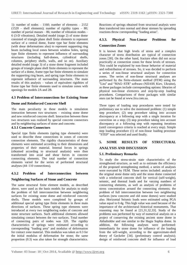
1): number of nodes – 1160; number of elements – 2152
(1520 – shell elements); number of rigidity types – 80;
number of partial masses – 86; number of vibration modes –
6 (3-D vibrations). Detailed model (stage 2) of stone dome
consisted of triangle plane shell finite elements to represent
surface of a central dome, frame type bar finite elements (with shear deformations also) to represent supporting ring
beam including local zones between window holes, spring
type finite elements to represent influence of surrounding
structures (including half-domes, cylindrical shells,
columns, periphery shells, walls, and so on). Auxiliary
detailed model (stage 3) of a stone dome fragment included
groups of triangle plane shell finite elements to represent the
surface of a dome, frame type bar finite elements to simulate
the supporting ring beam, and spring type finite elements to
represent influence of surrounding structures. The main
results of this analysis – values of equivalent rigidities of frame type bar finite elements used to simulate zones with
openings for models 2A and 2B.
4.3 Problem of Interconnections for Existing Stone
Dome and Reinforced Concrete Shell
The main peculiarity in these models is simulation
interaction between two structures – existing stone dome
and new reinforced concrete shell. Interaction between these
two structures was realized by special concrete connectors
and by neighboring surfaces of stone and concrete.
4.3.1 Concrete Connectors
Special type finite elements (spring type elements) were
used to describe these connections in zones of concrete
connection elements. The rigidity characteristics of these
elements were estimated according to their dimensions and
properties of their material. Internal forces in springs
(obtained according to structural analysis) were then transformed into axial and shear forces in concrete
connecting elements. The total number of connection
elements varied for the series of performed structural
analyses (44–110 connections).
4.3.2 Problem of Interconnection between
Neighboring Surfaces of Stone and Concrete
The same structural finite element models, as described
above, were used as the basis models for analysis to study
the problem of full interconnection between neighboring
surfaces for existing stone dome and reinforced concrete
shells. These models were completed by groups of
additional special spring type finite elements in three main
directions of surfaces. These spring type elements were introduced at every two neighboring nodes of concrete and
stone structure surfaces. Such additional elements allowed
simulating contact between the two surfaces. Total number
of connecting pairs of nodes was 320. The rigidity
characteristics of springs were estimated according to
corresponding "loading area" and modulus of deformation
for contact zone material. This modulus was taken as 0.3 for
the initial modulus of deformation for stone; the same
proportion (0.3) was also taken for strength characteristics.
Reactions of springs obtained from structural analysis were
then transferred into normal and shear stresses by spreading
reactions throw corresponding "loading areas".
4.3.3. Physical Non-Linear Problems for
Connection Zones
It is known that high levels of stress and a complex
character of stress distribution are typical of connection
zones [30]. On the other hand, fracture often did not occur practically at connection zones for these levels of stresses.
This could be explained by non-linear behavior of material
and redistribution of stresses. So, it was decided to perform
a series of non-linear structural analyses for connection
zones. The series of non-linear structural analyses are
performed by the finite-element method (FEM) using the
''Lira'' and “MAG~STR" software (NIIASS, Kiev, Ukraine),
as these packages include corresponding options: libraries of
physical non-linear elements and step-by-step loading
procedures. Comparisons of these packages with similar
ones can be found at www.lira.com.ua.
Three types of loading step procedures were tested for
preliminary use to solve the mentioned problem: (1) simple
step procedure; (2) step procedure taking into account
discrepancy at a following step with a single iteration for
correction on a step; (3) step procedure taking into account
discrepancy at a following step with repeating iterations
(until convergence criteria is reached at every step). Simple
step loading procedure (1) of non-linear loading processor
"STEP" was selected and used finally.
5. SOME RESULTS OF STRUCTURAL
ANALYSIS AND DISCUSSION
5.1. Preliminary Remarks
To study the stress-strain state characteristics of the
strengthened structure, as well as to estimate the efficiency
of the proposed strengthening method, a series of analyses were executed by FEM. These series included: analysis of
the original stone dome only and the stone dome connected
with a reinforced concrete shell for vertical (self-weight),
seismic, and thermal loads and for varying numbers of
connecting elements, as well as analysis of problems of
stress concentration around the connecting elements; the
problem of full interconnection between two neighboring
surfaces (new concrete and old stone domes) were studied
also. Horizontal Seismic loads were estimated using PGA
value equal to 0.4g. This high value was used because of the
importance of the architectural–historical monuments. That reasoning may be found at [21,31,32,33]. Study of the
problems was performed by way of numerical analysis on a
project of conserving the existing ancient stone dome in
Akhaltsikhe and one similar to the Hagia Sophia dome. In
addition, the following analyses were performed:
immediately for stone dome for influence of the loading
from the self-weight, according to the approximate-shell
theory of Geckeler [34]. (preliminary control analysis);
design of reinforced concrete shell for influence of load
IJRET: International Journal of Research in Engineering and Technology eISSN: 2319-1163 | pISSN: 2321-7308
_______________________________________________________________________________________
Volume: 03 Issue: 10 | Oct-2014, Available @ http://www.ijret.org 7
from the combined self-weight of the strengthened
(connected) structure (intensity of combined estimated load
at the top of the dome is 20 kN/m2), according to the
theories of limit analysis [35].
5.2. Main Results for Vertical and Seismic Loads
The main results of structural analysis are presented in Tables 1 and 2. The analysis of the stone dome connected
with the reinforced concrete shell was compared with that of
a stone dome alone.
Stone dome in Akhaltsikhe (Table 1): for vertical loads:
for example, membrane compression stresses were reduced
by 25–30%, membrane tension stresses were reduced by 75–
80%; for seismic loads: maximum membrane stresses (+/-)
were reduced by 95%, maximum vertical and horizontal
displacements (+/-) were reduced by about 50%.
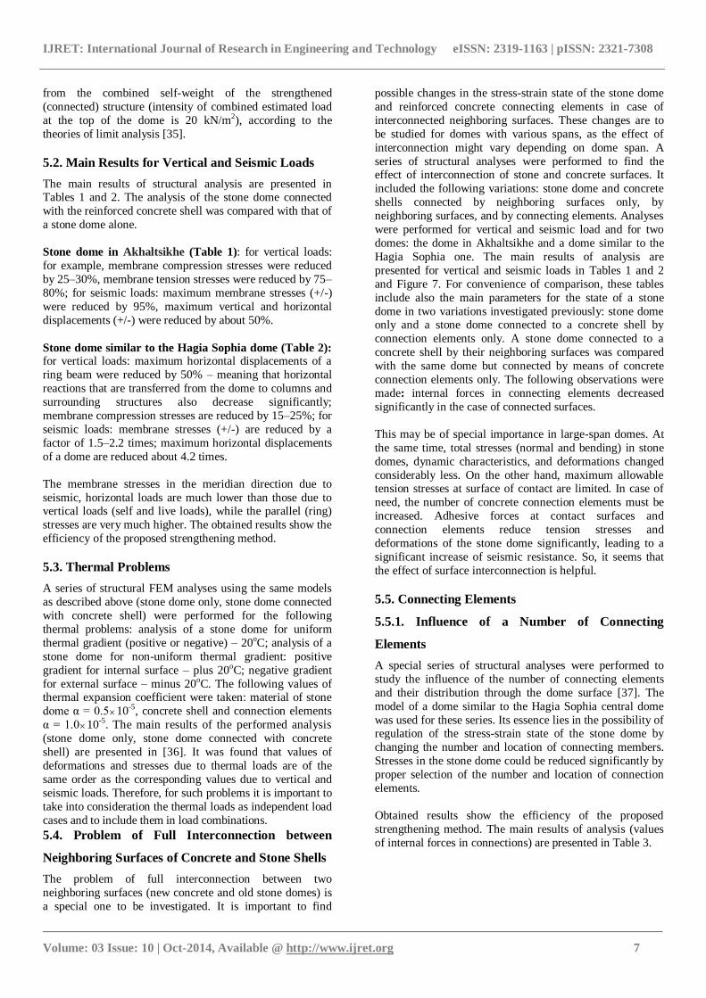
Stone dome similar to the Hagia Sophia dome (Table 2): for vertical loads: maximum horizontal displacements of a
ring beam were reduced by 50% – meaning that horizontal
reactions that are transferred from the dome to columns and
surrounding structures also decrease significantly;
membrane compression stresses are reduced by 15–25%; for
seismic loads: membrane stresses (+/-) are reduced by a
factor of 1.5–2.2 times; maximum horizontal displacements
of a dome are reduced about 4.2 times.
The membrane stresses in the meridian direction due to
seismic, horizontal loads are much lower than those due to vertical loads (self and live loads), while the parallel (ring)
stresses are very much higher. The obtained results show the
efficiency of the proposed strengthening method.
5.3. Thermal Problems
A series of structural FEM analyses using the same models
as described above (stone dome only, stone dome connected
with concrete shell) were performed for the following
thermal problems: analysis of a stone dome for uniform
thermal gradient (positive or negative) – 20oC; analysis of a
stone dome for non-uniform thermal gradient: positive
gradient for internal surface – plus 20oC; negative gradient
for external surface – minus 20oC. The following values of thermal expansion coefficient were taken: material of stone
dome α = 0.510-5, concrete shell and connection elements
α = 1.010-5. The main results of the performed analysis
(stone dome only, stone dome connected with concrete
shell) are presented in [36]. It was found that values of
deformations and stresses due to thermal loads are of the
same order as the corresponding values due to vertical and
seismic loads. Therefore, for such problems it is important to
take into consideration the thermal loads as independent load
cases and to include them in load combinations.
5.4. Problem of Full Interconnection between
Neighboring Surfaces of Concrete and Stone Shells
The problem of full interconnection between two
neighboring surfaces (new concrete and old stone domes) is
a special one to be investigated. It is important to find
possible changes in the stress-strain state of the stone dome
and reinforced concrete connecting elements in case of
interconnected neighboring surfaces. These changes are to
be studied for domes with various spans, as the effect of
interconnection might vary depending on dome span. A
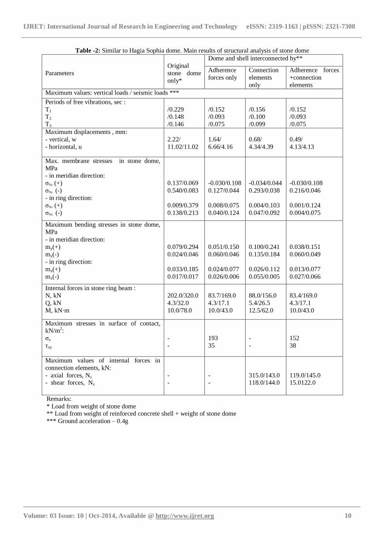
series of structural analyses were performed to find the effect of interconnection of stone and concrete surfaces. It
included the following variations: stone dome and concrete
shells connected by neighboring surfaces only, by
neighboring surfaces, and by connecting elements. Analyses
were performed for vertical and seismic load and for two
domes: the dome in Akhaltsikhe and a dome similar to the
Hagia Sophia one. The main results of analysis are
presented for vertical and seismic loads in Tables 1 and 2
and Figure 7. For convenience of comparison, these tables
include also the main parameters for the state of a stone
dome in two variations investigated previously: stone dome only and a stone dome connected to a concrete shell by
connection elements only. A stone dome connected to a
concrete shell by their neighboring surfaces was compared
with the same dome but connected by means of concrete
connection elements only. The following observations were
made: internal forces in connecting elements decreased
significantly in the case of connected surfaces.
This may be of special importance in large-span domes. At
the same time, total stresses (normal and bending) in stone
domes, dynamic characteristics, and deformations changed
considerably less. On the other hand, maximum allowable tension stresses at surface of contact are limited. In case of
need, the number of concrete connection elements must be
increased. Adhesive forces at contact surfaces and
connection elements reduce tension stresses and
deformations of the stone dome significantly, leading to a
significant increase of seismic resistance. So, it seems that
the effect of surface interconnection is helpful.
5.5. Connecting Elements
5.5.1. Influence of a Number of Connecting
Elements
A special series of structural analyses were performed to
study the influence of the number of connecting elements
and their distribution through the dome surface [37]. The
model of a dome similar to the Hagia Sophia central dome
was used for these series. Its essence lies in the possibility of regulation of the stress-strain state of the stone dome by
changing the number and location of connecting members.
Stresses in the stone dome could be reduced significantly by
proper selection of the number and location of connection
elements.
Obtained results show the efficiency of the proposed
strengthening method. The main results of analysis (values
of internal forces in connections) are presented in Table 3.

IJRET: International Journal of Research in Engineering and Technology eISSN: 2319-1163 | pISSN: 2321-7308
_______________________________________________________________________________________
Volume: 03 Issue: 10 | Oct-2014, Available @ http://www.ijret.org 8
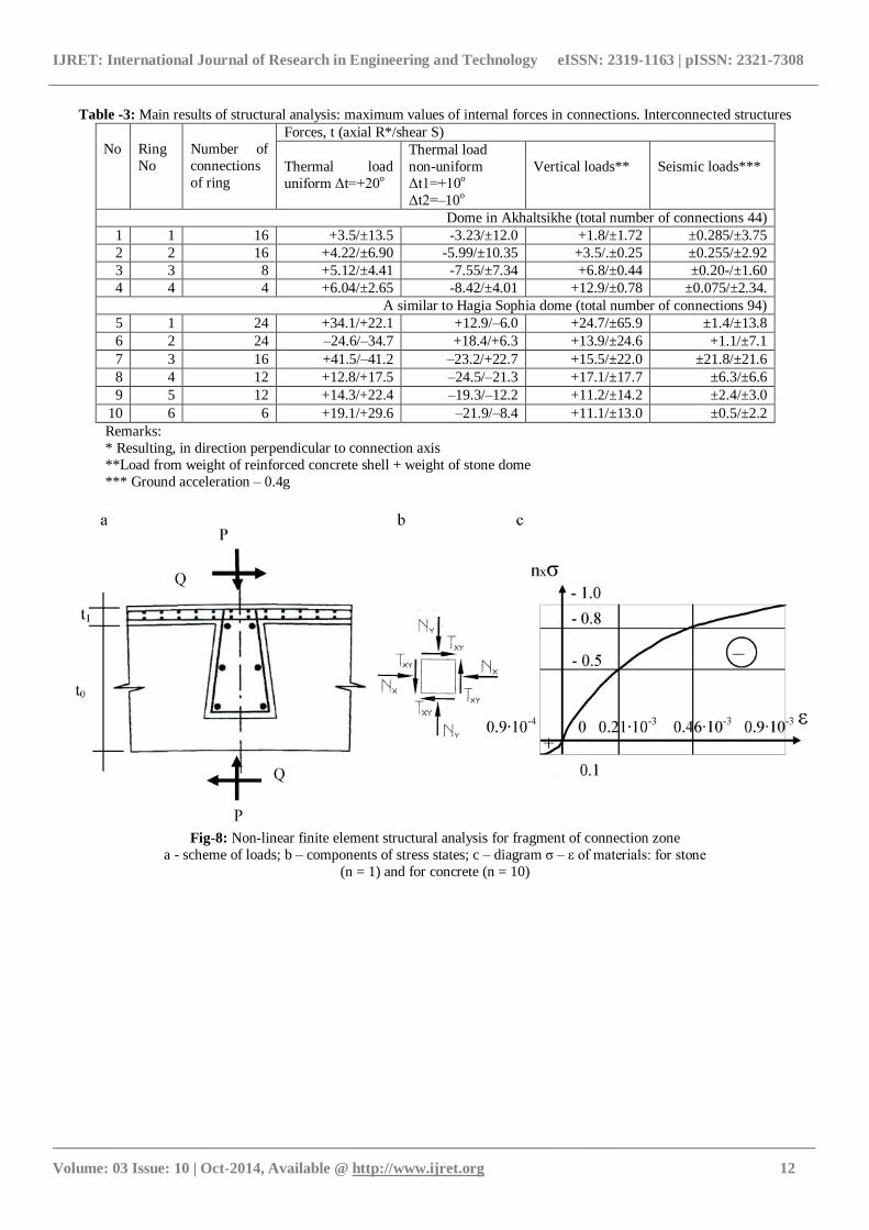
5.5.2. Stress Concentration Problem: Physical Non-
Linear Problems.
The structural models were two-dimensional extracts of a
structure which consisted of a reinforced concrete
connecting element and surrounding zones of the stone
dome. Two main schemes of load were examined for a
connecting element: 1–axial load, 2–pure shear (Fig. 8a);
components of the stressed state are presented in Figure 8b.
Two linear test problems were solved as a preliminary to more precisely defining the parameters of a finite-element
mesh. The influence of mesh density was tested here:
meshes of 6442 elements and 3422 elements were used.
Finally, a mesh of 3422 elements was chosen for non-
linear structural analysis, according to the results of
these preliminary test problems. The non-linear
structural model of a fragment consisted of a non-linear
plane triangular and rectangular finite elements; total
number of nodes is 960, total number of finite elements
– 1001. "Deformation-stress" streak lines with a number
of zones – 18 were used for the description of non-linear properties of materials (stone, concrete). Stress-strain
diagrams of materials are presented in Figure 7C. The step-
by-step load procedure included 22 steps of load, with
correction of results at every step. The state of the material
was checked at every load step during load increases.
Output information about the state of the material and
values of deformations and stresses is available; it allowed
us to follow the progress of damage accumulation and the
effects of stress redistribution and estimate dimensions of
zones with non-elastic deformations. The Balandin-Geniev
modified strength theory [38]. was used as a theory of
material strength. The main results of the series of FEM analyses are presented in at Figures 8, 9 and 10.

IJRET: International Journal of Research in Engineering and Technology eISSN: 2319-1163 | pISSN: 2321-7308
_______________________________________________________________________________________
Volume: 03 Issue: 10 | Oct-2014, Available @ http://www.ijret.org 9
Table -1: Dome in Akhaltsikhe. Main results of analysis
Parameters Original stone
dome only*
Dome and shell interconnected by **
adherence
forces only
connection
elements only
adherence forces
+connection
elements
Maximum values: vertical loads/seismic loads***
Periods of free vibrations, sec :
T1
T2
T3
/0.239
/0.129
/0.072
/0.235
/0.127
/0.048
/0.235
/0.127
/0.048
/0.234
/0.127
/0.047
Maximum displacements , mm
- vertical, w
- horizontal, u
2.24/
0.72/4.79
1.12/
0.26/4.42
1.40/
0.257/4.44
1.08/
0.255/4.36
Max. membrane stresses in stone dome, MPa,
- in meridian direction:
σNy (+)
σNy (-)
- in ring direction:
σNx (+)
σNx (-)
/0.070
0.360/0.050
0.082/0.070
0.099/0.109
/0.041
0.244/0.003
0.009/0.044
0.020/0.051
/0.035
0.292/0.007
0.009/0.045
0.063/0.065
/0.042
0.283/0.001
0.014/0.048
0.022/0.049
Max. bending stresses in stone dome, MPa
- in meridian direction:
my(+) my(-)
- in ring direction:
mx(+)
mx(-)
0.620/0.685 0.110/0.017
0.203/0.191
0.049/0.002
0.330/1.048 0.095/0.034
0.133/0.256
0.018/0.008
0.349/1.007 0.078/0.027
0.135/0.241
0.007/0.013
0.326/1.039 0.081/0.073
0.130/0.247
0.017/0.007
Internal forces in stone ring beams :
- ring beam 1: N, kN
Q, kN
My, kN·m
Mz, kN·m
- ring beam 2: N, kN
Q, kN
M, kN·m
24.5/78.0
12.0/89.0
17.0/175.4
10.0/
+114.0/±55.0
±37.0/60.0
-42.0/131.0
11.2/77.0
13.0/90.0
16.1/179.3
+41.0/34.0
±25.0/62.0
±29.0/134.0
11.4/77.0
13.0/89.0
16.0/178.4
7.0/
+41.0/33.0
±24.0/61.0
±29.0/132.0
+9.0/77.0
+13.0/±89.0
+16.0/177.0
7.5/
+39.8±36.0
±27.062.0
±23.0/±134.0
External forces in stone piers:
N, kN
Q, kN
M, kN·m
764.0/147.0
71.0/120.0
161.0/134.0
764.0/166.0
37.0/
92.0/247.0
765.0/166.0
40.5/
100.0/250.0
764.0/167.0
39.0/17.0
95.0/255.0
Maximum stresses in surface of contact ,
kN/m2:
σz
τxy
-
-
-
-
+99/81
-82/
-/99
-52/
-
-
-
-
+103/43
-1
+44/47
-10/
Maximum values of internal forces in
connection elements, kN:
- axial forces, Nz
- shear forces, Nx(Ny)
98.3/71.0
25.0/105.0
-132.0/51.0
+18.5/83.0
Remarks: * Load from weight of stone dome
** Load from weight of reinforced concrete shell + weight of stone dome
*** Ground acceleration – 0.4g
IJRET: International Journal of Research in Engineering and Technology eISSN: 2319-1163 | pISSN: 2321-7308
_______________________________________________________________________________________
Volume: 03 Issue: 10 | Oct-2014, Available @ http://www.ijret.org 10
Table -2: Similar to Hagia Sophia dome. Main results of structural analysis of stone dome
Parameters
Original
stone dome
only*
Dome and shell interconnected by**
Adherence
forces only
Connection
elements
only
Adherence forces
+connection
elements
Maximum values: vertical loads / seismic loads ***
Periods of free vibrations, sec :
T1 T2
T3
/0.229 /0.148
/0.146
/0.152 /0.093
/0.075
/0.156 /0.100
/0.099
/0.152 /0.093
/0.075
Maximum displacements , mm:
- vertical, w
- horizontal, u
2.22/
11.02/11.02
1.64/
6.66/4.16
0.68/
4.34/4.39
0.49/
4.13/4.13
Max. membrane stresses in stone dome,
MPa - in meridian direction:
σNy (+)
σNy (-)
- in ring direction:
σNx (+)
σNx (-)
0.137/0.069
0.540/0.083
0.009/0.379
0.138/0.213
-0.030/0.108
0.127/0.044
0.008/0.075
0.040/0.124
-0.034/0.044
0.293/0.038
0.004/0.103
0.047/0.092
-0.030/0.108
0.216/0.046
0.001/0.124
0.004/0.075
Maximum bending stresses in stone dome,
MPa
- in meridian direction:
my(+)
my(-)
- in ring direction:
mx(+)
mx(-)
0.079/0.294
0.024/0.046
0.033/0.185
0.017/0.017
0.051/0.150
0.060/0.046
0.024/0.077
0.026/0.006
0.100/0.241
0.135/0.184
0.026/0.112
0.055/0.005
0.038/0.151
0.060/0.049
0.013/0.077
0.027/0.066
Internal forces in stone ring beam :
N, kN
Q, kN
M, kN·m
202.0/320.0
4.3/32.0
10.0/78.0
83.7/169.0
4.3/17.1
10.0/43.0
88.0/156.0
5.4/26.5
12.5/62.0
83.4/169.0
4.3/17.1
10.0/43.0
Maximum stresses in surface of contact, kN/m2:
σz
τxy
-
-
193
35
-
-
152
38
Maximum values of internal forces in
connection elements, kN:
- axial forces, Nz
- shear forces, Nx
- -
- -
315.0/143.0 118.0/144.0
119.0/145.0 15.0122.0
Remarks:
* Load from weight of stone dome ** Load from weight of reinforced concrete shell + weight of stone dome
*** Ground acceleration – 0.4g
IJRET: International Journal of Research in Engineering and Technology eISSN: 2319-1163 | pISSN: 2321-7308
_______________________________________________________________________________________
Volume: 03 Issue: 10 | Oct-2014, Available @ http://www.ijret.org 11
Fig-7: Stone dome connected with concrete shell
a - dome in Akhalthsikhe; b – similar to Hagia Sophia dome A, B – vertical loads; C, D – seismic loads.
σz – normal stresses, kPa; τxy – shear stresses, kPa;
adherence forces only;
adherence forces + connection elements
IJRET: International Journal of Research in Engineering and Technology eISSN: 2319-1163 | pISSN: 2321-7308
_______________________________________________________________________________________
Volume: 03 Issue: 10 | Oct-2014, Available @ http://www.ijret.org 12
Table -3: Main results of structural analysis: maximum values of internal forces in connections. Interconnected structures
No
Ring
No
Number of
connections
of ring
Forces, t (axial R*/shear S)
Thermal load
uniform Δt=+20o
Thermal load
non-uniform
Δt1=+10o
Δt2=–10o
Vertical loads**
Seismic loads***
Dome in Akhaltsikhe (total number of connections 44)
1 1 16 +3.5/±13.5 -3.23/±12.0 +1.8/±1.72 ±0.285/±3.75
2 2 16 +4.22/±6.90 -5.99/±10.35 +3.5/.±0.25 ±0.255/±2.92
3 3 8 +5.12/±4.41 -7.55/±7.34 +6.8/±0.44 ±0.20-/±1.60
4 4 4 +6.04/±2.65 -8.42/±4.01 +12.9/±0.78 ±0.075/±2.34.
A similar to Hagia Sophia dome (total number of connections 94)
5 1 24 +34.1/+22.1 +12.9/–6.0 +24.7/±65.9 ±1.4/±13.8
6 2 24 –24.6/–34.7 +18.4/+6.3 +13.9/±24.6 +1.1/±7.1
7 3 16 +41.5/–41.2 –23.2/+22.7 +15.5/±22.0 ±21.8/±21.6
8 4 12 +12.8/+17.5 –24.5/–21.3 +17.1/±17.7 ±6.3/±6.6
9 5 12 +14.3/+22.4 –19.3/–12.2 +11.2/±14.2 ±2.4/±3.0
10 6 6 +19.1/+29.6 –21.9/–8.4 +11.1/±13.0 ±0.5/±2.2
Remarks:
* Resulting, in direction perpendicular to connection axis
**Load from weight of reinforced concrete shell + weight of stone dome
*** Ground acceleration – 0.4g
Fig-8: Non-linear finite element structural analysis for fragment of connection zone
a - scheme of loads; b – components of stress states; c – diagram σ – ε of materials: for stone
(n = 1) and for concrete (n = 10)
IJRET: International Journal of Research in Engineering and Technology eISSN: 2319-1163 | pISSN: 2321-7308
_______________________________________________________________________________________
Volume: 03 Issue: 10 | Oct-2014, Available @ http://www.ijret.org 13
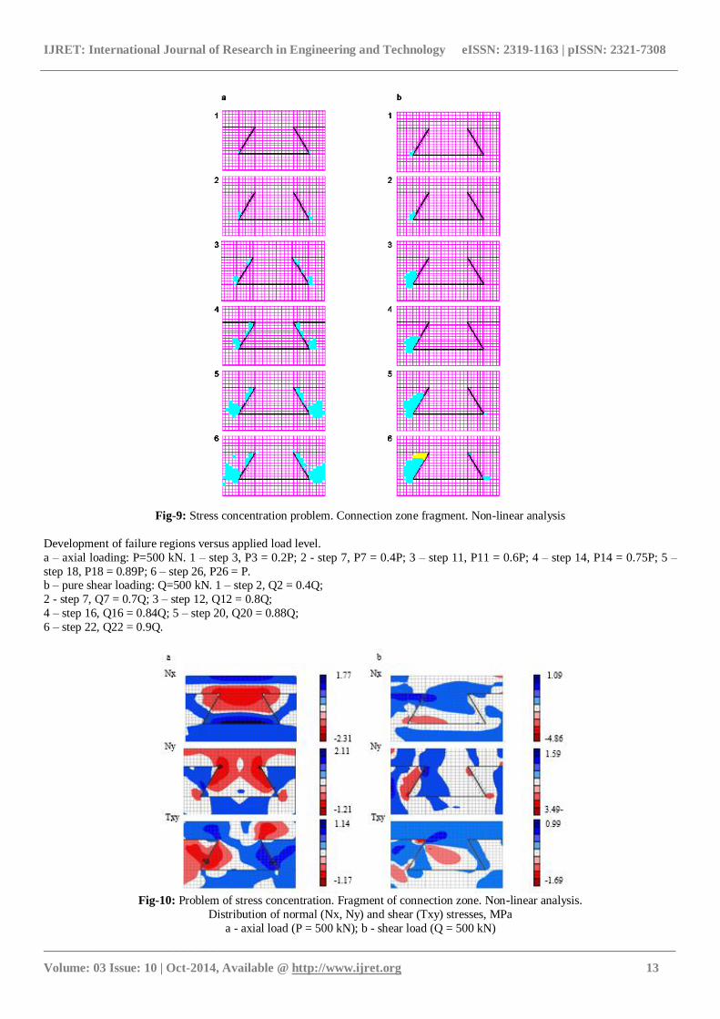
Fig-9: Stress concentration problem. Connection zone fragment. Non-linear analysis
Development of failure regions versus applied load level.
a – axial loading: P=500 kN. 1 – step 3, P3 = 0.2P; 2 - step 7, P7 = 0.4P; 3 – step 11, P11 = 0.6P; 4 – step 14, P14 = 0.75P; 5 –
step 18, P18 = 0.89P; 6 – step 26, P26 = P. b – pure shear loading: Q=500 kN. 1 – step 2, Q2 = 0.4Q;
2 - step 7, Q7 = 0.7Q; 3 – step 12, Q12 = 0.8Q;
4 – step 16, Q16 = 0.84Q; 5 – step 20, Q20 = 0.88Q;
6 – step 22, Q22 = 0.9Q.
Fig-10: Problem of stress concentration. Fragment of connection zone. Non-linear analysis.
Distribution of normal (Nx, Ny) and shear (Txy) stresses, MPa
a - axial load (P = 500 kN); b - shear load (Q = 500 kN)
IJRET: International Journal of Research in Engineering and Technology eISSN: 2319-1163 | pISSN: 2321-7308
_______________________________________________________________________________________
Volume: 03 Issue: 10 | Oct-2014, Available @ http://www.ijret.org 14
It was found that stresses in a stone dome could reach high
values for zones near concrete connection elements.
Therefore, it could be recommended to provide special
preliminary preparation of a stone surface for the zones of
connection elements. For example, concrete spraying of
high-strength material (with compression-breaking stress – 200 kg/cm2 and more) with a thickness of 2–3 cm could be
used.
6. CONCLUSIONS
An original dome strengthening structure is proposed to
enable durability of ancient domes against seismic forces
during severe earthquakes without significant damage, and
at the same time to preserve the existing ancient appearance
of the inner surface in its present state of antiquity. It
consists of a new thin-walled reinforced concrete shell with
a supporting ring, cast on top of the existing stone dome.
The connection between old stone dome and new reinforced
concrete shell (structure of strengthening) is achieved by using special reinforced concrete connecting elements and
by adhesion of the neighboring surfaces. The concrete
connecting elements protrude as pins out of the reinforced
concrete shell, have the form of a truncated pyramid, and
penetrate into the stone dome. They are distributed
throughout the entire surface of the strengthened dome.
Thus, an ''interconnected stone-reinforced concrete
structure'' is created. The efficiency of the proposed method
is shown by numerical analysis of vertical, thermal, and
seismic loads with the use of FEM, on examples of
Akhalthsikhe and of one similar to Hagia Sophia stone domes. Its essence lies in: the potential regulation of the
stress-strain state of the stone dome by means of changing
the quantity and location of connecting members; stresses
and strain in the stone dome are significantly decreased;
supporting constructions are significantly unloaded due to
the decrease of the horizontal forces, as the thrust is wholly
absorbed by the reinforced concrete supporting ring. As a
result, the earthquake resistance of the stone domes
increases significantly.
ACKNOWLEDGEMENTS
The authors are thankful to the Dr. G. Sirotin (Ariel
University, Ariel, Israel) for his assistance in preparing this article for publication.
REFERENCES
[1]. Mark R, Westagard A. The first dome of the Hagia
Sophia: myth vs. technology. Domes from Antiquity to the
Present. Proc. of the IASS-MSU Int. Symposium. Istanbul,
1988, pp. 163-172.
[2]. Meyer-Christian W. Hagia Sophia, the engineers
planning of Anthemios and Isidoros. Proc. of the IASS-
MSU Int. Symposium. Istanbul, 1988, pp. 173-190.
[3]. Sundaram R. Historic dome built in south India during
17th century. Proc. of the IASS-MSU Int. Symposium.
Istanbul, 1988, pp. 205-215.
[4]. Pizzetti and Fea. Restoration and strengthening of the
elliptical dome of Vicoforte Sanctuary. Proc. of the IASS-
MSUInt.Symposium.Istanbul,1988, pp. 289-308.
[5]. Heyman J. The stone skeleton – structured engineering
of masonry architecture. Cambridge University Press, 1995,
252. pp. [6]. Krautheimer R., Ćurčić S. Early Christian and
Byzantine architecture. Penguin Books Ltd., 1986, 350 pp.
[7]. Harries K. A. Quake resistance in ancient Rome.
Concrete International, 19 (1), 1997, pp. 55-58.
[8]. Structural Analysis of Historical Constructions, 5th
International Conference New Delhi, India, 2006
[9]. Penelis G., Karavesiroglou M., Stylianidis K,
Leontaridis D. The Rotunda of Theassaloniki: seismic
behavior of Roman and Byzantine structures. Hagia Sophia
from the Age of Justinian to the Present. Edited by Mark R.
and A. Ş. Calmak. Cambridge University Press, 1992, pp. 132-157.
[10]. Danieli (Danielashvili) M., Gabrichidze G., Goldman
A., Sulaberidse O. Experience in restoration and
strengthening of stone made ancient domes in seismic
regions. Proc. of 7th US NCEE, Boston, Massachusetts,
USA, vol. II, 2002, pp. 1167-1175.
[11]. Sesigur H., Celik O.C., Cili F. Repair and strenghening
of ancient structures. First European Conference on
Earthquake Engineering and Seismology, Geneva,
Switzerland, 2006, paper No1387.
[12]. Poland C.D, Reis E.M.The repair and strengthening of
historic Stanford Memorial Church. Tenth World Conference. Balkema, Rotterdam, 1992, pp. 5341-5346.
[13]. Gabrilovich P., Richard P. Methodology for
strengthening and repair of earthquake damaged monuments
in Pagan- Burma. Proc. of Eight World Conference on
Earthq. Engin., San– Francisco, USA, vol. 1, 1984, pp. 609-
616.
[14]. Rabin I.S. Structural analysis of historic buildings:
restoration, preservation and adaptive application for
architects and engineers. Hancobci J. Wiley & Sons. 2000.
240 pp.
[15]. Repair and strengthening of historical monuments and buildings in urban nuclei. Building construction under
seismic conditions in the Balkan region, UNDP/UNIDO
project rep/79/015. Vienna. 1984, 296 pp
[16]. Ziyaeifar M., Meshki H., Rajaei M. Rehabilitation of
historical buildings subjected to seismic hazards, a
methodology. 13th World Conference on Earthquake
Engineering. Vancouver, B.C., Canada, 2004, paper No.
1598.
[17]. Sofronie R.A., Crisan R., Toanchina M. Retrofitting
the masonry of cultural heritage. Fifth National Conference
on Earthquake Engineering, 2003, Istanbul, Turkey, paper
No. AE-013, (SD R). [18]. Danieli M., Bloch J. . Rehabilitation of the religious
heritage in seismic regions: Principle and practice.
Protection of Historical Buildings. PROHITECH
09.Proceedings of the international conference on protection
of historical buildings, PROHITECH 09, Rome, Italy, 21-
24 June 2009, Ed. Federico M.Mazzolani, vol. 1,CRC,
Press/Balkema, 2009 Taylor & Francis Group, London, UK,
pp. 125-130.

IJRET: International Journal of Research in Engineering and Technology eISSN: 2319-1163 | pISSN: 2321-7308
_______________________________________________________________________________________
Volume: 03 Issue: 10 | Oct-2014, Available @ http://www.ijret.org 15
[19]. Danieli M., Bloch J. Principle, practice and experience
of rehabilitation of the historical buildings in seismic
regions. In: Proceedings of the 15th World Conference on
Earthquake Engineering (15WCEE), September,24-28,
2012, Lis A.bon, Portugal, pp.1-9, Paper No 392.
[20]. Danieli M, Aronchik . Case study: The strengthening and seismic safety of the Oni synagogue in Georgia. In:
Proceedings of the 13th International Conference on
Structures under Shock and Impact (SUSI XIII). WIT Press,
2014, pp. 456-466.
[21]. Paret T.,Freeman S.,Searer G., Hachem M., Gilmarin
U. Seismic evaluation and strengthening of an historic
synagogue using traditional and innovatie methods and
materials. First European Conference on Earthquake
Engineering and Seismology, Geneva, Switzerland, 2006,
paper No 701.
[22]. Danielashvili M., Gabrichidze G., Melashvili Y., Sulaberidze O. Study of some reinforced and metal spatial
structures in seismic regions of Georgia. Proc ICSS-98, vol.
I, Moscow, 1998, pp. 396-403.
[23]. Engineering Analysis of the Racha Earthquake
Consequences in Georgia, 1991. Editor Gabrichidze G.,
Metsniereba, 1996, Tbilisi, Georgia. 235 pp.
[24]. Emerson W. and Van Nice, R. L. Hagia Sophia,
Istanbul: Preliminary report of a recent examination of the
structure. Supplement to American Journal of Archaeology,
1943, Volume XLVII, pp. 403-416.
[25]. Kato S., Aoki T.,Hidaka K., Nakamura H. Finite-
element modeling of the first and second domes of Hagia Sophia. Hagia Sophia from the Age of Justinian to the
Present. Edited by Mark R. and A. Ş. Calmak. Cambridge
University Press, 1992, pp. 103-119.
[26]. Mark R., Çacmac A.Ş. Preliminary report on an
integrated study of the structure of Hagia Sophia: past,
present and future. Hagia Sophia from the Age of Justinian
to the Present. Edited by Mark R. and A. Ş. Calmak.
Cambridge University Press, 1992,. 120-130.
[27]. Mainstone R.J. Questioning Hagia Sophia. Hagia
Sophia from the Age of Justinian to the Present. Edited by
Mark R. and A. Ş. Calmak. Cambridge University Press, 1992,, pp. 158-176.
[28]. Aoki T., Kato S., Ishikawa K., Hidaka K., Yorulmaz
M., Gili F. Principle of structural restoration for Hagia
Sophia Dome. Proc. of STREMAH Int. Symposium, San
Sebastian, 1997, 6, pp. 467-476.
[29]. Aoki T., Chiorino M., Roccani R. Structural
characteristics of the elliptical masonry dome of the
Sanctuary of the Vicoforte. Proc. of the First International
Congress on Construction History, 2003, Madrid
[30]. Timoshenko S. Strength of materials. Part II. 3rd
edition. Toronto, New York, London. 1956. 360 pp.
[31]. Danieli (Danielashvili) M., Zaalishvili L. Correlation of seismic activity with the architectural-historical
inheritance in the northern Georgia. First European
Conference on Earthquake Engineering and Seismology,
Geneva, Switzerland, 2006, paper No: 1303, (SD-R).
[32]. Karaesmen E., Unay A.I., Erkay C., Boyaci N. Seismic
behavior of old masonry structures. Earthquake
Engineering. Tenth World Conference. Balkema,
Rotterdam, 1992, pp. 4531-4536.
[33]. Cuadra C., Karkee M.B., Ogava J., Rojas J. An
evaluation of earthquake risk to Inca's historical
constructions. 13th World Conference on Earthquake
Engineering. Vancouver, B.C., Canada, 2004, paper No.150
(SD-R).
[34]. Timoshenko S.P., Woinovsky-Kriger S. Theory of plates and shells. 2nd edition. McGraw-Hill, New York,
Toronto, London, 350 pp. 1959
[35]. Akhvlediani N.A., Danielashvili M.A. Limit analysis
of reinforced concrete shells, Arkhivum Inzynezii Ladowey,
Tom XXXVI, Z 3, Warsaw, Poland, 1990, pp. 187-205.
[36]. Danieli (Danielsvilli) M., Aronchik A, Bloch,. J.
Seismic safety of an ancient stone dome strengthened by an
original method. 13th World Conference on Earthquake
Engineering. Vancouver, B.C., Canada, 2004, (SD-R) paper
No 2789.
[37]. Bloch J., Aronchik A., Goldman A., Danieli (Danielashvili) M. A Method of Strengthening Ancient
Domes and Vaults, and Problems of their Stress – Strain
States in Seismic Regions. Wessex Institute of Technology,
UK. ERES IV 22-24 September 2003, Ancona, Italy. Publl.,
In .HPSM 2004 WIT Press Southampton, Boston, 2004,611-
620
[38]. Balandin A., Geniev G. Strength theory of stone and
concrete. Moscow, Stroizdat,1972. 160 pp.
BIOGRAPHIES
Dr. Moshe Danieli is a civil engineer,
from GTU, Tbilisi (1961), Ph.D from
GPEHTBI, Tbilisi (1972), Senior scientist in Strength of Materials and
Structural Mechanics, from ASSU,
Moscow (1977). Since 2002 he is a
senior lecturer in the Dept of Civil
Engineering, Ariel University, Israel.
Arcady Aronchik is a structural
engineer, Ph.D from Central Research
Institute of Building Structures
(TCNIISK), Moscow, Russia (1981),
MSc from Riga Technical University
(RTU), Latvia, (1971). He deals with structural FEM analysis and the design
of civil and industrial buildings.
Dr. Jaacov Bloch is a civil engineer
(B.Sc., 1962, M.Sc., 1964) from
Technion, Israel, Dr.Sc., 1974. He
founded the Department of Civil
Engineering at the Ariel College of
Samaria (Ariel University at present)
and headed the Department for 12
years. Dr. J. Bloch is currently an associate professor.