an overview of hydraulic fracturing
TRANSCRIPT
An Overview of Hydraulic Fracturing
P d b h lf f hPresented on behalf of the Petroleum Technology Research Centre (PTRC)
Weyburn, SK
Bethany KurzEnergy & Environmental Research Center (EERC)
Grand Forks, North Dakota
© 2012 University of North Dakota Energy & Environmental Research Center.

Presentation Overview
• What is an oil reservoir?• Brief history of hydraulic fracturing.• What is hydraulic fracturing?• What are the components of fracture fluids?• The facts behind
hydraulic fracturinghydraulic fracturing concerns and possible risks.
The International Center for Applied Energy Technology® http://www.planetseed.com/node/15250

Terminology
Hydraulic fracturingy g
– Hydrofracking– Fracking– Fraccing
(f ’ )– Fracing (frac’ing)– Frac jobs
Fracture stimulation– Fracture stimulation– Well stimulation
The International Center for Applied Energy Technology®

How Do Oil/Gas Reservoirs Form?
• Reservoir: A subsurface “pool” of hydrocarbons t i d ithi f t d b f kcontained within porous or fractured subsurface rocks.
– Not an actual cavern or void space. • The hydrocarbons (oil/gas) originally began as organicThe hydrocarbons (oil/gas) originally began as organic
matter (plankton, plants, animal remains, etc…) that was buried and compressed by other layers of sediment.
• After burial the pressure and temperature increase• After burial, the pressure and temperature increase, essentially “cooking” the plant and animal matter into oil and gas.Th il d ft i t f th i i h• The oil and gas often migrate away from the organic-rich source rock and accumulate in underground “traps.”
The International Center for Applied Energy Technology®


Hydrocarbon Formation
The International Center for Applied Energy Technology®
http://need-media.smugmug.com/Graphics/Graphics/i-n5JP5Fd/0/L/oilNaturalGasFormationPrimary-L.jpg

Sedimentary Basins of North America
The International Center for Applied Energy Technology®

Williston Basin
The International Center for Applied Energy Technology®

Williston Basin Cross Section
The International Center for Applied Energy Technology®
Source: North Dakota Geological Survey
Porosity and Permeability
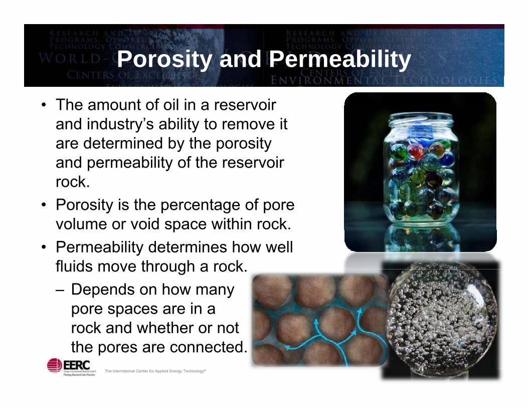
• The amount of oil in a reservoir and industry’s ability to remove itand industry s ability to remove it are determined by the porosity and permeability of the reservoir
krock.• Porosity is the percentage of pore
volume or void space within rock.p• Permeability determines how well
fluids move through a rock.– Depends on how many
pore spaces are in a rock and whether or not
The International Center for Applied Energy Technology®
rock and whether or not the pores are connected.

Permeability
• Rocks that transmit fluids readily, such as sandstones, are permeable and have many p y(relatively) large, well-connected pores.
• Impermeable rocks tend to be finer-grained such as shales and siltstones withshales and siltstones, with smaller, fewer, or less interconnected pores.
The International Center for Applied Energy Technology®

Historical Oil/Gas Extraction
• Historically, oil and gas reservoirs were in rocks that had y, grelatively high permeability and/or porosity – “low hanging fruit.”With d i h i t l d illi d h d li• With advances in horizontal drilling and hydraulic fracturing, industry is now able to economically extract oil and gas from unconventional reservoirs, meaning rocks that have low porosity and permeability.
The International Center for Applied Energy Technology®

Brief Explanation of Hydraulic Fracturing
• A technique used to extract oil and gas from very “tight” q g y grocks (low permeability) in the subsurface.
• To produce oil and gas from these reservoirs, a mixture f t t d t l d h i lof water, proppant, and, to a lesser degree, chemical
additives, is injected into the reservoir at high pressures to create fractures in the rock.
• These fractures create a pathway for hydrocarbons to move through the reservoir to be extracted.
The International Center for Applied Energy Technology®

History of Hydraulic Fracturing
• The first experimental fracturing operation was conducted i 1947 b St li d Oil i th H t Fi ld (in 1947 by Stanolind Oil in the Hugoton Field (gas-producing limestone) located in southwestern Kansas (Montgomery and Smith, 2010). ( g y )
– Utilized 1000 gallons of napalm (gelled
li ) d dgasoline) and sand from the Arkansas River.
The International Center for Applied Energy Technology®

History of Hydraulic Fracturing (continued)(continued)
• In 1949, an exclusive license for the hydraulic fracturing , y gprocess was granted to the Halliburton Oil Well Cementing Company. O M h 17 1949 H llib t f d th fi t t• On March 17, 1949, Halliburton performed the first two commercial hydraulic fracturing treatments in Stephens County, Oklahoma, and Archer County, Texas (Montgomery and Smith, 2010).
The International Center for Applied Energy Technology®

Early Hydraulic Fracturing Operations
Vintage 1950s remotely controlled fracture pumper powered by surplus WWII
The International Center for Applied Energy Technology®
Vintage 1950s remotely controlled fracture pumper powered by surplus WWII Allison aircraft engines (Montgomery and Smith, 2010).

Times Have Changed
The International Center for Applied Energy Technology®
http://www.cuadrillaresources.com/what-we-do/hydraulic-fracturing/history/

The International Center for Applied Energy Technology®

The International Center for Applied Energy Technology® 20

Where Is Hydraulic Fracturing at Today?
• Over 2.5 million hydraulic fracture treatments have been yconducted globally.
• Over 1.0 million wells have been hydraulically fractured i th U it d St tin the United States.
• Vertical drilling and hydraulic fracturing have shifted to horizontal drilling and fracturing.horizontal drilling and fracturing.
• Hydraulic fracturing has evolved from a single stage operation to multiple stages (40 plus).
• Lateral lengths (in the Bakken) can extend for 10,000 feet.
The International Center for Applied Energy Technology®

Horizontal vs. Vertical Drilling
The International Center for Applied Energy Technology®
http://ny.water.usgs.gov/projectsummaries/CP30/Marcellus_Presentation_Williams.pdf

Common Issues in the Media
• Water availability, especially in arid and semiarid areasarid and semiarid areas.
• Public perception of how much water is needed for hydraulic fracturing.
• Concerns over water quality and hydraulic fracture flowback disposal. p
• Potential impacts of hydraulic fracturing on underground supplies of drinking water.– Precautions are taken to protect groundwater supplies
when a well is drilled and subsequently fractured.– Hydraulic fracturing has been successfully employed
The International Center for Applied Energy Technology®
– Hydraulic fracturing has been successfully employed for over 60 years.

EPA’s Hydraulic Fracturing Study
• Congress directed the U.S. Environmental Protection gAgency (EPA) to study the relationship between hydraulic fracturing and drinking water.P i l i t l t th t ti l i t f• Primary goal is to evaluate the potential impact of hydraulic fracturing on surface and subsurface drinking water supplies.
• A Scientific Advisory Board (SAB) was formed to advise the study.
Of th 23 b l f t ffili t d ith– Of the 23 members, only four are not affiliated with a university.
The International Center for Applied Energy Technology®

Spread of Public Misconceptions
The International Center for Applied Energy Technology®

Groundwater Protection
How deep is 7700 feet?feet? • More than six Empire
State Buildings stacked end to end
• 1½ times deeper than the deepest part of the Grand Canyon
• More than 25 football• More than 25 football fields laid out goal line to goal line
The International Center for Applied Energy Technology®

Fracture Propagation
The International Center for Applied Energy Technology®
http://ny.water.usgs.gov/projectsummaries/CP30/Marcellus_Presentation_Williams.pdf

Regulation of Oil and Gas Drilling and ProductionProduction
• Each oil and gas producing state and/or province has g p g pregulations in place to project drinking water supplies and other natural resources.
• There are regulations in place for:There are regulations in place for:– permitting– well construction– hydraulic fracturing– temporary abandonment– well plugging– well plugging– tanks and pits– waste handling and spills.
The International Center for Applied Energy Technology® http://www.drillingahead.com/photo/crown‐drilling‐rig‐reserve‐pit

Water Needs for Hydraulic Fracturing
• Requires anywhere from ~ 3 to 5 million gallons of water per 3 to 5 million gallons of water per well.
• The water is mixed with various additives prior to injection.
• A percentage of the water returns to the surface (flowback) and isto the surface (flowback) and is recovered and disposed of (or recycled).– Typically contains dissolved
solids (salts), suspended solids, residual hydrocarbons, and
The International Center for Applied Energy Technology®
residual hydrocarbons, and hydraulic fracturing constituents.

How Much Water Is 4 million gallons?
• The approximate amount of water used to irrigate a 1-square mile section of land for one day in western Northsquare-mile section of land for one day in western North Dakota.
• 1% of the average daily water withdrawal for once-g ythrough cooling at a 400-MW coal-fired power plant.
• About 1/5 of the average daily water use in Regina, SK.
The International Center for Applied Energy Technology®
http://localism.com/sk/regina

Water Hauling and Tank Storage
• Water is transported to well sites in 7500- to 8000-gallon tankerin 7500 to 8000 gallon tanker trucks.
• Water is stored on-site in 21,000-gallon tanks.
The International Center for Applied Energy Technology®

Common Hydraulic Fracturing Fluid ConstituentsConstituents
• Freshwater → Usually high quality, but that is changing.P t T i ll d i b d th t h l• Proppant → Typically sand or ceramic beads that help keep the fractures open following fracturing (approximately 3 to 5 million pounds of proppant used per operation).p p pp p p )
• Biocides → Reduce the risk of well souring from microbes.• Friction-reducing agents (“slick water”) → Surfactants that
t fl id flpromote fluid flow.• Polymers → Form gels to keep proppants in suspension.• Scale inhibitors → Reduce scale formation in pipes• Scale inhibitors → Reduce scale formation in pipes.• Weak acids → Help dissolve minerals that cement pore
spaces.
The International Center for Applied Energy Technology®

What Are Fracturing Fluids?
The International Center for Applied Energy Technology®
Slide Courtesy of S. Baumgartner, Marathon Oil

Hydraulic Fracturing Fluid Chemical DisclosureDisclosure
• Increasing public pressure to disclose information on fracturing fluid chemistryfracturing fluid chemistry.– EPA is encouraging voluntary public disclosure.– No federal rules yet, but some states require disclosure y q
(Wyoming, Alaska, Pennsylvania, Colorado, Texas).• The Ground Water Protection Council and the Interstate
Oil and Gas Compact Commission have developed aOil and Gas Compact Commission have developed a chemical registry Web site.– Voluntary disclosure of fracture fluid y
chemical information.– 25 companies have contributed so far, many of which
are major oil producers
The International Center for Applied Energy Technology®
are major oil producers.

Options for Flowback Disposal
• Underground injectiong j• Discharge to a commercial industrial treatment facility• Discharge to a municipal wastewater treatment plant• Discharge to surface water bodies (usually following
treatment)Reuse• Reuse– Blending with
freshwater– Recycling
The International Center for Applied Energy Technology® Photo: VWS Oil and Gas

Multiwell Pads
• Horizontal drilling allows for placement of several wells at g pone location.
• Benefits:– Reduced surface impacts (fewer well pads, pipelines,
roads, etc…)– Increased drilling efficiency (rigs move tens of feet– Increased drilling efficiency (rigs move tens of feet,
rather than miles, to drill the next well)– Reduced truck traffic– Allows for more efficient oil and gas production
The International Center for Applied Energy Technology®

Multiwell Pad Example
Continental’s ECO-Pad concept is being employed in the BakkenBakken.– Reduced surface impact by as much as 75%– Significant time and cost savings (10% cost savings for a g g ( g
four-well pad)
Additional Drilling Sites
The International Center for Applied Energy Technology®
Photos: Continental Resources
Sites

What Are the Risks of Groundwater or Surface Contamination?or Surface Contamination?
• The risk of groundwater contamination from hydraulic fracturing is approximately equal to dying from falling out g pp y q y g gof bed.
• The risk of a hydraulic fracturing fluid spill, even in concentrated form is less than the risk of spills from theconcentrated form, is less than the risk of spills from the delivery of gasoline and diesel fuel at the neighborhood convenience store.
The International Center for Applied Energy Technology®

Does Hydraulic Fracturing Cause Earthquakes?Earthquakes?
• Fracturing can result in “microseismic” events.Th l t i i i t d d h d• The largest microseismic event ever recorded had a measured magnitude of about 0.8 on a normalized scale, which is approximately 2000 times less energy than a pp y gymagnitude 3.0 earthquake. (Like a person jumping.)
• In most cases, microseismic energy ranges from 10,000 to 1 000 000 times less energy than a 3 0 magnitudeto 1,000,000 times less energy than a 3.0 magnitude quake.
The International Center for Applied Energy Technology®
Source: www.energyfromshale.org

Projected U.S. Energy Use
78% of projected future energy use is from fossil fuels (non‐renewable)
The International Center for Applied Energy Technology®
Source: Energy Information Administration, 2011, http://www.eia.gov/neic/speeches/newell_12162010.pdf

Projected Domestic Gas Production
The International Center for Applied Energy Technology®
Source: Energy Information Administration, 2011, www.eia.gov/neic/speeches/newell_12162010.pdf.

Global Liquids Production
The International Center for Applied Energy Technology®
Source: Energy Information Administration, 2011, http://www.eia.gov/neic/speeches/newell_12162010.pdf

Contact Information
Energy & Environmental Research CentergyUniversity of North Dakota15 North 23rd Street, Stop 9018Grand Forks ND 58202-9018Grand Forks, ND 58202-9018
World Wide Web: www.undeerc.orgT l h N (701) 777 5050Telephone No. (701) 777-5050Fax No. (701) 777-5181
Bethany Kurz, Senior Research [email protected]
The International Center for Applied Energy Technology®