an overview of ship hydroelasticity
TRANSCRIPT
AN OVERVIEW OF SHIP
HYDROELASTICITY
Ivo Senjanović, Nikola Vladimir University of Zagreb,
Faculty of Mechanical Engineering
and Naval Architecture
Croatia
Šime Malenica Bureau Veritas, Research Department
Paris, France

2 An overview of ship hydroelasticity
Contents
INTRODUCTION
RESEARCH TECHNIQUES
SELECTED PROJECTS ON SHIP HYDROELASTICITY
NUMERICAL SIMULATIONS
CONCLUSION

3 An overview of ship hydroelasticity
HYDROELASTICITY
A branch of science concerned with the motion and distortion of deformable
bodies responding to environmental excitations in the sea (Chen et al., 2006).
A discipline concerned with phenomena involving interaction between inertial,
hydrodynamic and elastic forces (Heller and Abramson, 1959).
According to Heller and Abramson (1959): the naval counterpart to
aeroelasticity - the fluid pressure acting on the structure modifies its dynamic
state and, in return, the motion and distortion of the structure disturb the
pressure field around it.
Hydroelasticity of Ships was brought to the attention of the Naval
Architecture community in the 1970s through the work of Bishop and Price,
culminating with the publication of the synonymous book in 1979.
Comprehensive reviews of advances in ship hydroelasticity
Jensen and Madsen (1977), Wu (1987, 1994), Suo and Guo (1996), Kashiwagi
(2000), Chen et al. (2006), Hirdaris and Temarel (2009)...
ISSC reports regularly review advances in numerical approaches, model tests
and full-scale measurements with hydroelastic effects included.
Introduction
4 An overview of ship hydroelasticity
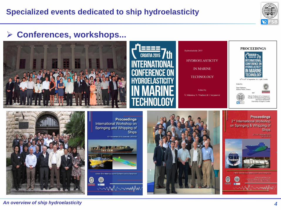
Conferences, workshops...
Specialized events dedicated to ship hydroelasticity

5 An overview of ship hydroelasticity
Important phenomena
SPRINGING & WHIPPING
Springing is usually defined as the continuous global ship structural
vibrations induced by water waves. Springing is a resonant phenomenon
in contrast to the whipping which is the transient ship vibrational response
induced by impulsive loading (slamming, green water, underwater
explosion,...).
Typical springing (left) and whipping (right) ship structural response;
Top - total signal, bottom - filtered signal (Malenica et al., 2008)

6 An overview of ship hydroelasticity
Existing rules of Classification societies cover only limited
size and types of structures
Mainly quasi-static approach
High frequency hydroelastic contribution
either neglected either included empirically
Methodology for inclusion of hydroelastic effects still “open”
Reliability of different hydroelastic models
Realistic operational profile
Statistical post-processing
• Extreme
• Fatigue
Harmonization of rules and direct calculation approaches
Design methodology within direct calculation approach should not contradict
the existing rule values for existing ships!
• Choice of reasonable operating conditions?
• Choice of representative probability levels?
Background
7 An overview of ship hydroelasticity
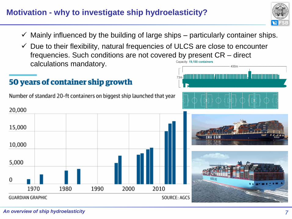
Motivation - why to investigate ship hydroelasticity?
Mainly influenced by the building of large ships – particularly container ships.
Due to their flexibility, natural frequencies of ULCS are close to encounter
frequencies. Such conditions are not covered by present CR – direct
calculations mandatory.

8 An overview of ship hydroelasticity
Motivation - why to investigate ship hydroelasticity?
9 An overview of ship hydroelasticity
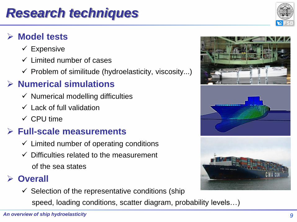
Model tests
Expensive
Limited number of cases
Problem of similitude (hydroelasticity, viscosity...)
Numerical simulations
Numerical modelling difficulties
Lack of full validation
CPU time
Full-scale measurements
Limited number of operating conditions
Difficulties related to the measurement
of the sea states
Overall
Selection of the representative conditions (ship
speed, loading conditions, scatter diagram, probability levels…)
Research techniques

10 An overview of ship hydroelasticity
Classification of ship hydroelasticity tests
Ref. Jiao et al.: Model testing for ship
hydroelasticity: A review and future
trends, J. Shanghai Jiaotong
Univ. 22(6):641-650, 2017

11 An overview of ship hydroelasticity
Model tests
Detailed reviews regularly given in ISSC Reports
Earlier review of model tests – Wu (2003)
Recent tests with segmented models (reviewed in ISSC 2018)
321 m long 10000 TEU container ship (Kim et al., 2015; Hong et al., 2015) –
WILS JIP Project
425 m long 500000 DWT ore carrier (Li et al., 2016)
350 m long 450000 DWT ore carrier (Kim et al., 2015)
112 m long catamaran (Lavroff et al., 2017; Davis et al., 2017)

12 An overview of ship hydroelasticity
Model tests
Model types
Segmented, flexible backbone models
Hinged models
Fully flexible models (difficulties...)
Experiments in CEHIPAR, Madrid, Spain,
Project TULCS
Segmented barge, experiments in BGO First, Toulon,
France

13 An overview of ship hydroelasticity
Full-scale measurements
Detailed reviews also regularly given in ISSC Reports
Full-scale measurements reported in ISSC 2018
2800 TEU container ship (Gaidai et al., 2016)
2800 and 4440 TEU container ships (Mao et al., 2015)
4400, 8600, 9400 and 14000 TEU container ships (Andersen, 2014)
8400 and 8600 TEU container ships (Storhaug & Kahl, 2015)
8600 TEU container ship (Barhoumi & Storhaug, 2014)
14000 TEU container ship (Ki et al., 2015)
4600 and 14000 TEU container ships (Kahl et al., 2015)
8600, 9400 and 14000 TEU container ships (Andersen & Jensen, 2015)
4600 and 14000 TEU container ships and a LNG carrier (Kahl et al., 2016)
56 m naval high speed light craft (Magoga et al., 2016)
Several container ships and blunt ships (Storhaug et al., 2017)
210 m Ro-Lo ship (Orlowitz & Brandt, 2014)

14 An overview of ship hydroelasticity
Schematic presentation of measuring
points on the container ship Rigoletto
(EU FP7 Project TULCS)
Full-scale measurements
ISSC 2018 conclusions on full-scale measurements
Full-scale measurements and model tests in recent years have been focused
on unconventional ships such as VLCS and ULCS (probably influenced by
MSC Napoli and MOL Comfort cases)
The effects of sea state, heading, speed, size, loading condition, trade and
structural location are often discussed
Most studies are related
to vertical vibration
Recommended to pay
more attention to
torsional vibrations and
other topics, such as
acceleration levels for
cargo securing
15 An overview of ship hydroelasticity
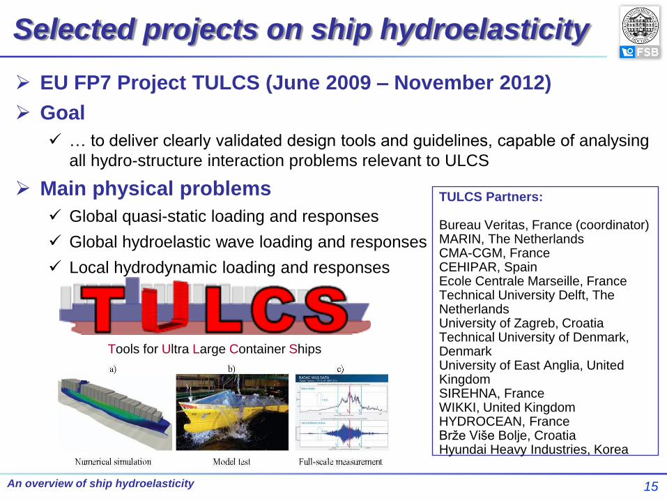
Selected projects on ship hydroelasticity
EU FP7 Project TULCS (June 2009 – November 2012)
Goal
… to deliver clearly validated design tools and guidelines, capable of analysing
all hydro-structure interaction problems relevant to ULCS
Main physical problems
Global quasi-static loading and responses
Global hydroelastic wave loading and responses
Local hydrodynamic loading and responses
Tools for Ultra Large Container Ships
TULCS Partners: Bureau Veritas, France (coordinator) MARIN, The Netherlands CMA-CGM, France CEHIPAR, Spain Ecole Centrale Marseille, France Technical University Delft, The Netherlands University of Zagreb, Croatia Technical University of Denmark, Denmark University of East Anglia, United Kingdom SIREHNA, France WIKKI, United Kingdom HYDROCEAN, France Brže Više Bolje, Croatia Hyundai Heavy Industries, Korea

16 An overview of ship hydroelasticity
GCRC-SOP
Background
ASERC (Advanced Ship Engineering Research Center) at PNU
Center of Excellence designated by Korean government in the Naval
Architecture and Ocean Engineering field in 2002 (Period 2002 – 2011)
GCRC-SOP (Global Core Research Center for Ships and
Offshore Plants)
Establish the world premier research center at PNU through the succession of
ASERC and the strategic international collaboration with world-renowned
researchers in the field of Ship & Offshore Plant Engineering (Period 2011-
2021)
GCRC-SOP Participants
National Research Foundation of Korea, Pusan National University, Pusan
Metropolitan City, Shipyards (HHI, DSME, SHI, STX , BNC, CreaTech),
Classification societies (ABS, BV, NK, KR)
4 External Universities
University of Michigan, University of Maryland, University of New Orleans,
UNIZAG FSB (with Bureau Veritas, Paris, France)

17 An overview of ship hydroelasticity
GCRC-SOP
GCRC SOP Cooperative Network

18 An overview of ship hydroelasticity
JRPs/JDPs within GCRC-SOP (as a Master Project)
Global hydroelastic response of LNG ships
Joint Development Project (PNU, BV, UNIZAG FSB & HHI)
Goal: to develop hydroelastic model for ships with internal liquid (LNGC,
Tankers…)
• Beam structural model
• 3DFE structural model
Scope of work:
• Example ship provided by HHI
• UNIZAG FSB - beam hydroelastic model
• BV & UNIZAG FSB - 3D FEM hydroelastic model
• PNU - semi analytical solution for validation purposes

19 An overview of ship hydroelasticity
JRPs/JDPs within GCRC-SOP (as a Master Project)
Springing & Whipping Analysis of HHI SkyBench™ container
carrier
Joint Research Project (UNIZAG FSB & HHI)

20 An overview of ship hydroelasticity
Numerical simulations
Solving hydroelastic problem at different levels of complexity
and accuracy
Structural models
• Beam structural model
• 3D FEM structural model
Hydrodynamic models
• Potential flow theories
• CFD

21 An overview of ship hydroelasticity
Sophisticated beam structural model
Beam model can give accurate results at global level
Based on the advanced thin-walled girder theory
• shear influence on bending and torsion
• accounting for contribution of transverse bulkheads to hull stiffness in a reliable way
• accounting for closed engine room structure segment in a proper way
Shear influence on torsion
• Analogy with shear influence on bending
Refs. Pavazza (2005), Senjanović et al. (2009)
, b bb s s
s
EI ww w w w
GA x
2
2
2
2, w t
t s s
s
EI
GI x

22 An overview of ship hydroelasticity
Sophisticated beam structural model
Contribution of transverse bulkheads to the global hull stiffness
• Theory of torsion of thin-walled girders
• Theory of bending of an ortothropic plate
• Core idea: Increase St. Venant torsional modulus of open hull cross-section
Discontinuities of ship hull
Bulkhead deformation due to hull cross-section warping

23 An overview of ship hydroelasticity
Sophisticated beam structural model
Equivalent torsional modulus
2
1 0
4 11 2.4
g s
t t t t
t
U UCaI I C I I
l I l E
Longitudinal section of container ship hold

24 An overview of ship hydroelasticity
Sophisticated beam structural model
Contribution of engine room structure to the hull stiffness (relatively short
closed segment)
Solution: Modelling of engine room structure as an open segment of increased
torsional stiffness due to influence of the decks
25 An overview of ship hydroelasticity
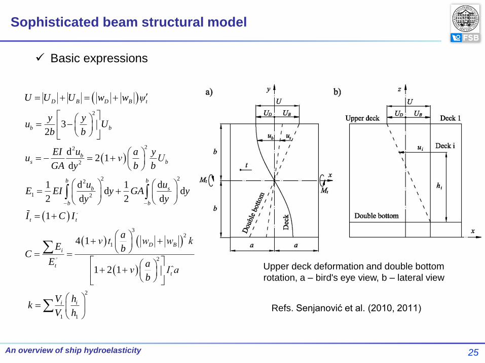
Sophisticated beam structural model
Basic expressions
2
22
2
2 22
1 2
32
1
2
1
32
d2 1
d
d d1 1d d
2 d 2 d
1
4 1
1 2 1
D B D B t
b b
bs b
b b
b s
b b
t t
D Bi
t
t
i
U U U w w ψ
y yu U
b b
uEI a yu ν U
GA y b b
u uE EI y GA y
y y
I C I
aν t w w k
E bC
E aν I a
b
Vk
V
2
1
ih
h
Upper deck deformation and double bottom
rotation, a – bird's eye view, b – lateral view
Refs. Senjanović et al. (2010, 2011)

26 An overview of ship hydroelasticity
Assessing cross-sectional parameters (STIFF software)

27 An overview of ship hydroelasticity
Validation of beam structural model
Comparison of twist angles for segmented pontoons with and wihout
bulkheads (Beam & 3D FEM models)
28 An overview of ship hydroelasticity
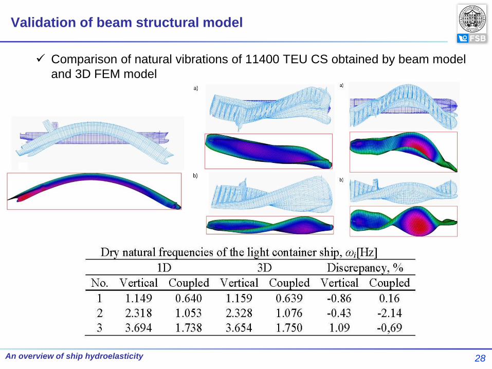
Validation of beam structural model
Comparison of natural vibrations of 11400 TEU CS obtained by beam model
and 3D FEM model
29 An overview of ship hydroelasticity
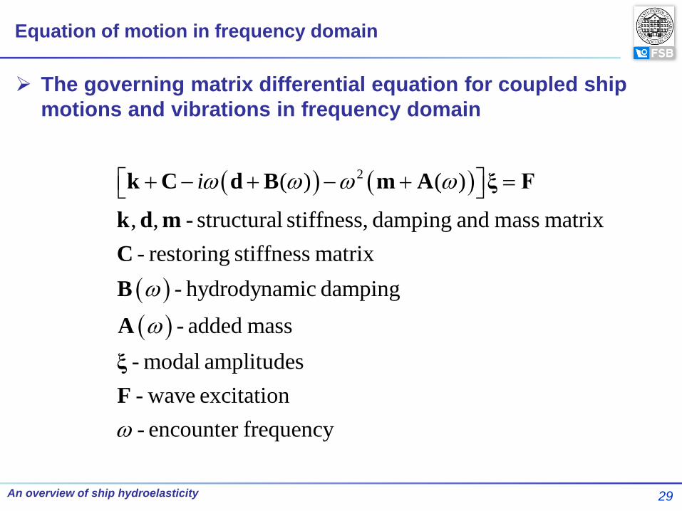
Equation of motion in frequency domain
2( ) ( )
, , - structural stiffness, damping and mass matrix
- restoring stiffness matrix
- hydrodynamic damping
- added mass
- modal amplitudes
- wave excitation
- en
i k C d B m A ξ F
k d m
C
B
A
ξ
F
counter frequency
The governing matrix differential equation for coupled ship
motions and vibrations in frequency domain

30 An overview of ship hydroelasticity
Validation of beam structural model
Comparison of transfer functions obtained by beam hydroelastic model and 3D
hydroelastic model (in both cases hydrodynamic potential flow model)
Transfer function of vertical bending moment,
χ=120°, V=15.75 kn
Transfer function of torsional moment, χ=120°,
V=15.75 kn
Transfer function of horizontal bending
moment, χ=120°, V=15.75 kn

31 An overview of ship hydroelasticity
Time domain simulation models

32 An overview of ship hydroelasticity
Time domain simulation models

33 An overview of ship hydroelasticity
Time domain simulation models
Slamming (strip approach)
Two slamming models:
• Generalized Wagner
• Modified Logvinovich

34 An overview of ship hydroelasticity
Time domain simulation models

35 An overview of ship hydroelasticity
HOMER software (Bureau Veritas)
Numerical models – Application of commercial software

36 An overview of ship hydroelasticity
Direct calculation methodologies
WhiSp methodology (Bureau Veritas NR583)
37 An overview of ship hydroelasticity
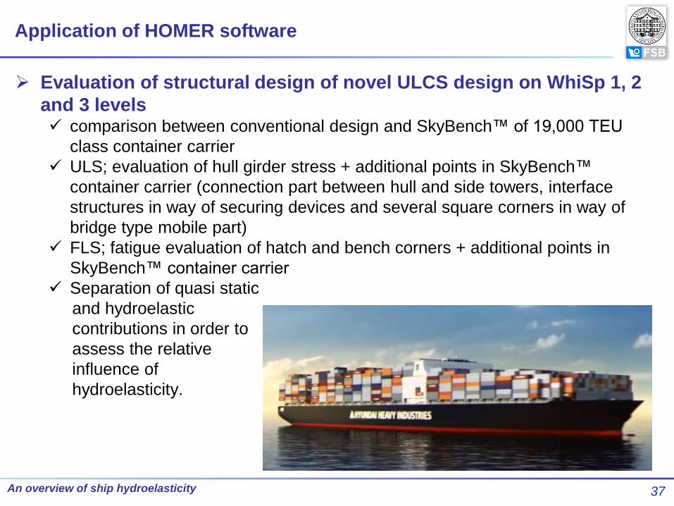
Evaluation of structural design of novel ULCS design on WhiSp 1, 2
and 3 levels comparison between conventional design and SkyBench™ of 19,000 TEU
class container carrier
ULS; evaluation of hull girder stress + additional points in SkyBench™
container carrier (connection part between hull and side towers, interface
structures in way of securing devices and several square corners in way of
bridge type mobile part)
FLS; fatigue evaluation of hatch and bench corners + additional points in
SkyBench™ container carrier
Separation of quasi static
and hydroelastic
contributions in order to
assess the relative
influence of
hydroelasticity.
Application of HOMER software

38 An overview of ship hydroelasticity
Application of HOMER software
Integration mesh Hydro mesh
FE meshes
Global and local models
39 An overview of ship hydroelasticity
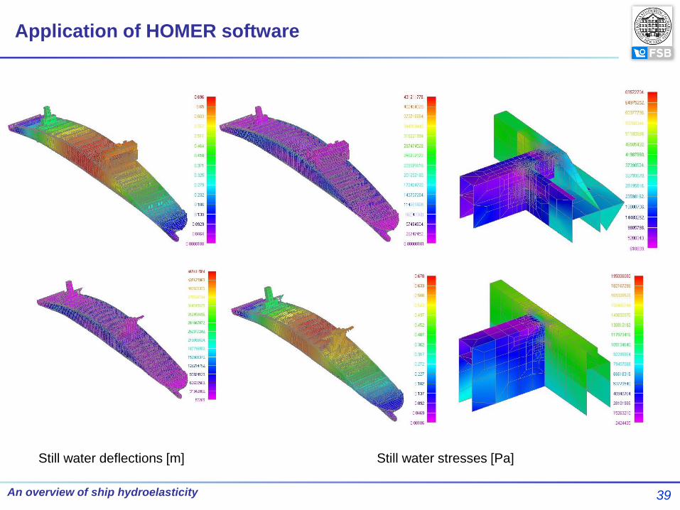
Application of HOMER software
Still water deflections [m] Still water stresses [Pa]

40 An overview of ship hydroelasticity
Application of HOMER software
Stress RAO sample with springing effect included Procedure flowchart

41 An overview of ship hydroelasticity
Application of HOMER software
Results WhiSp1 - Fatigue damage ratios

42 An overview of ship hydroelasticity
Typical VBM time history amidships
VBM upcrossing extrema distribution
U
R
MM
Criterion
Application of HOMER software
Results

43 An overview of ship hydroelasticity
Application of HOMER software
Results Whisp 2 – Relative influence of whipping on VBM
WhiSp 3 – Relative influence of whipping on fatigue
44 An overview of ship hydroelasticity
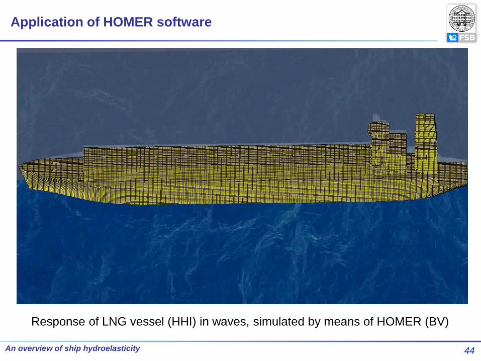
Response of LNG vessel (HHI) in waves, simulated by means of HOMER (BV)
Application of HOMER software
45 An overview of ship hydroelasticity
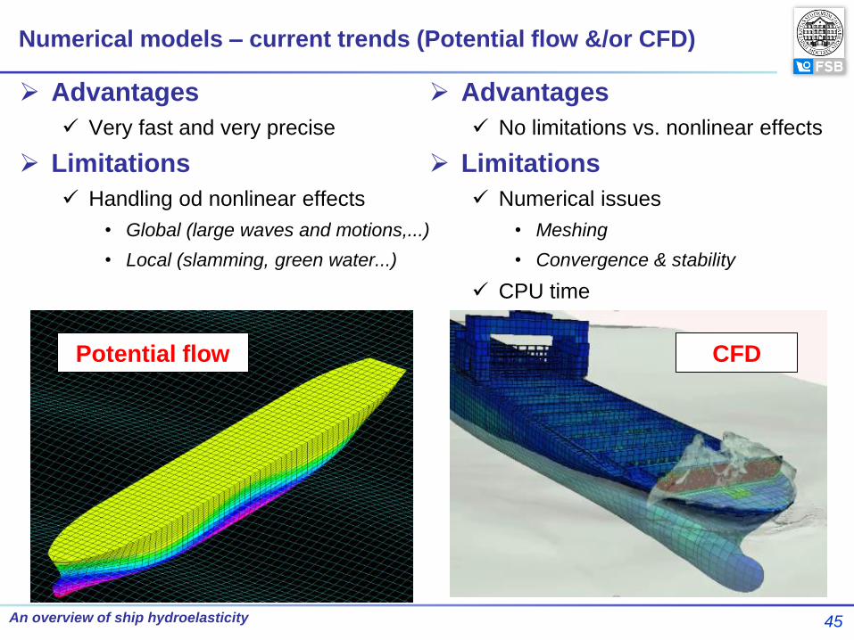
Numerical models – current trends (Potential flow &/or CFD)
Advantages
Very fast and very precise
Limitations
Handling od nonlinear effects
• Global (large waves and motions,...)
• Local (slamming, green water...)
Advantages
No limitations vs. nonlinear effects
Limitations
Numerical issues
• Meshing
• Convergence & stability
CPU time
Potential flow CFD
46 An overview of ship hydroelasticity
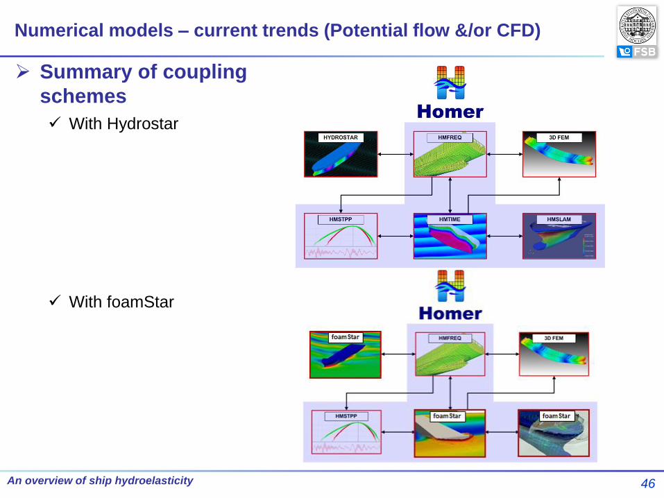
Numerical models – current trends (Potential flow &/or CFD)
Summary of coupling
schemes
With Hydrostar
With foamStar
47 An overview of ship hydroelasticity
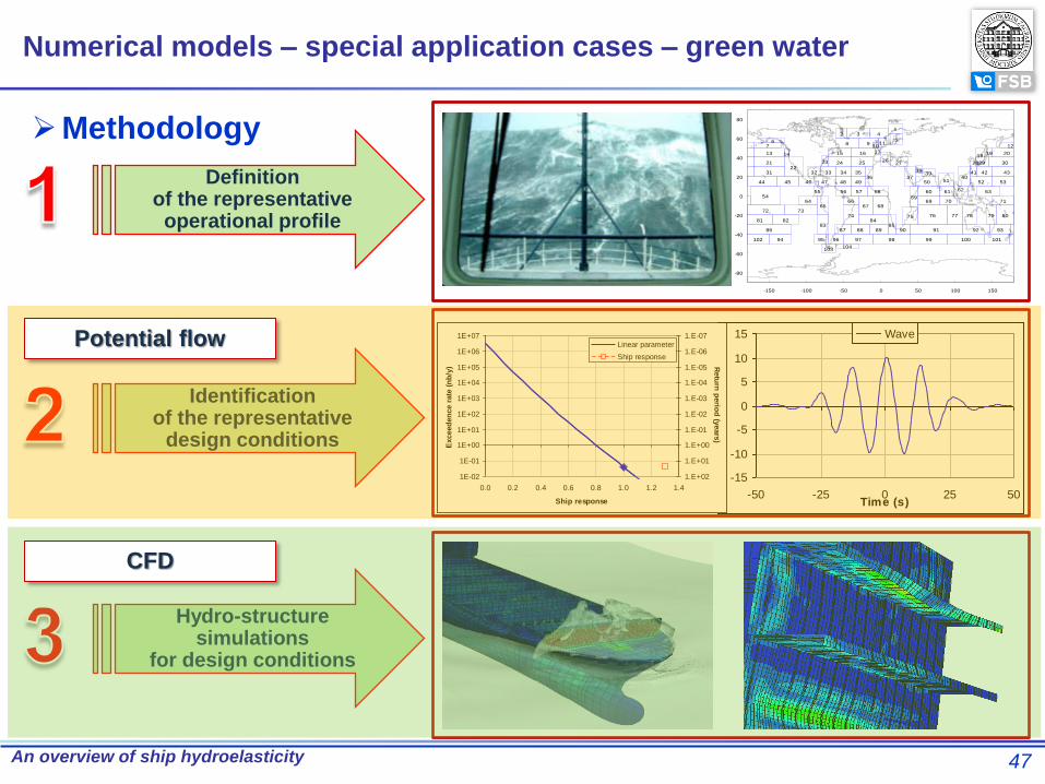
Methodology
-80
-60
-40
-20
0
20
40
60
80
-150 -100 -50 0 50 100 150
12 3 4
567
8 910
1112
13 14 15 16 1718
19 20
2122
23 24 2526
27 2829 30
31 32 33 34 3536 37
3839
4041 42 43
44 45 46 47 48 49 50 51 52 53
5455 56 57 58
59
60 61 62 63
6465
6667 68
69 70 71
72 7374 75 76 77 78 79 80
81 8283
8485
86 87 88 89 90 91 92 93
94 95 96 97 98 99 100 101102
103104
-15
-10
-5
0
5
10
15
-50 -25 0 25 50Time (s)
Wave
1E-02
1E-01
1E+00
1E+01
1E+02
1E+03
1E+04
1E+05
1E+06
1E+07
0.0 0.2 0.4 0.6 0.8 1.0 1.2 1.4
Ship response
Exceed
en
ce r
ate
(n
b/y
)
1.E-07
1.E-06
1.E-05
1.E-04
1.E-03
1.E-02
1.E-01
1.E+00
1.E+01
1.E+02
Retu
rn p
erio
d (y
ears
)
Linear parameter
Ship response
Identification of the representative
design conditions
Definition of the representative operational profile
Hydro-structure simulations
for design conditions
Potential flow
CFD
Numerical models – special application cases – green water

48 An overview of ship hydroelasticity
Numerical models – special application cases – green water
RWE RAO
1E-02
1E-01
1E+00
1E+01
1E+02
1E+03
1E+04
1E+05
1E+06
1E+07
0 5 10 15
Exceed
en
ce r
ate
(n
b/y
ear)
0.0000001
0.000001
0.00001
0.0001
0.001
0.01
0.1
1
10
100
Retu
rn p
eri
od
(year)
Long term RWE -80
-60
-40
-20
0
20
40
60
80
-150 -100 -50 0 50 100 150
12 3 4
567
8 910
1112
13 14 15 16 1718
19 20
2122
23 24 2526
27 2829 30
31 32 33 34 3536 37
3839
4041 42 43
44 45 46 47 48 49 50 51 52 53
5455 56 57 58
59
60 61 62 63
6465
6667 68
69 70 71
72 7374 75 76 77 78 79 80
81 8283
8485
86 87 88 89 90 91 92 93
94 95 96 97 98 99 100 101102
103104
A=Long_Term / RAO_max
Design waves
Dominant loading parameter – relative wave elevation
Bureau Veritas & UNIZAG FSB
49 An overview of ship hydroelasticity
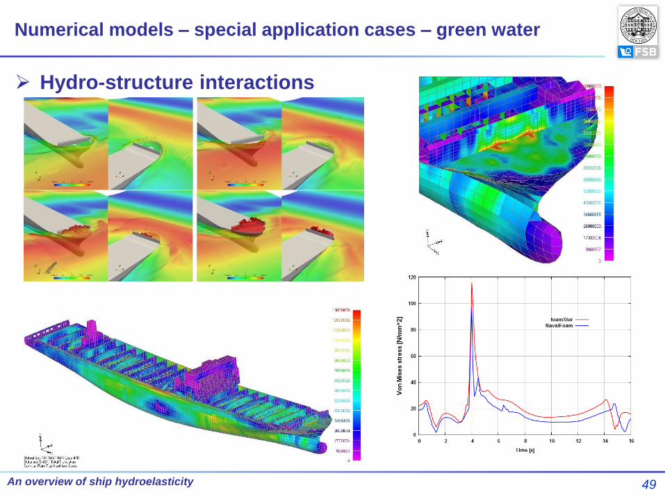
Numerical models – special application cases – green water
Hydro-structure interactions

50 An overview of ship hydroelasticity
Numerical models – special application cases – green water
JRP within GCRC-SOP (BV, UNIZAG FSB, HHI)
Determination of design waves (Hydrostar)
CFD simulations (OpenFOAM)
Structural analysis (NASTRAN)
Coupling (HOMER coupling scheme)
51 An overview of ship hydroelasticity
An overview of ship hydroelasticity is given
Emphasis on numerical models developed within projects involving UNIZAG
FSB and Partners (Bureau Veritas, Pusan Natl. Univ., Hyundai Heavy
Industries, etc.) – particularly TULCS and GCRC-SOP
Hydroelasticity of ships is still „open” issue – beside numerical codes still
should be investigated by model tests and full-scale measurements
Development of hydroelastic numerical codes and direct calculation
methodologies should be done simultaneously (Example: HOMER & WhiSp)
Trends in development of numerical codes: coupling of 3D FEM tools with CFD
tools
Application of hydroelastic theories becomes wider (simplified models including
plates and stiffened panels, wedge-shaped bodies, ice-sheets, ships, very
large floating structures, propellers, offshore structures, etc.)
Conclusion

Thanks for Your Attention!!!
Thanks to our Partners