an overview of the developmental process for the modular ... · the natural function of the human...
TRANSCRIPT
JOHNS HOPKINS APL TECHNICAL DIGEST, VOLUME 30, NUMBER 3 (2011) 207
their natural limb. In Phase 1, the leveraging of COTS products coupled with prototypical technology devel-opment was demonstrated in the 7-degree-of-freedom (DOF) Prototype 1 system, which was fully patient tested in a clinical environment using noninvasive neural integration strategies. Prototype 2 improved upon this technological foundation to solidify subsystem design approaches and prove the viability of a highly dexterous (22+ DOF) system.
At the system level, Phase 1 required the identifica-tion of advanced scientific research and engineering concepts to identify viable integration pathways to meet Phase 2 objectives. The ultimate deliverable for Phase 1 was a Systems Integration Plan to address the following topics: engineering development road maps, additional
INTRODUCTIONIn 2005, the Defense Advanced Research Projects
Agency (DARPA) started the Revolutionizing Prosthet-ics program in an effort to restore natural limb function to war fighters who had suffered limb amputations in the line of duty. Because prosthetic technology at the time was still rooted in concepts generated decades ago, the potential advancement in restorative function that advanced prosthetic devices could provide would be rev-olutionary. After two phases of development, DARPA envisioned by the end of 2009 a fully functional and neurally integrated prosthetic device that could mimic the natural function of the human limb to the extent that current technology would allow. DARPA charged that the device should look, feel, weigh, perform, and seamlessly integrate with the human user as if it were
he development of the Modular Prosthetic Limb (MPL) has and continues to be the result of cutting-edge technology innovation in mechanical, electri-
cal, and software design. Sound systems engineering practices have laid the foundation for the successes achieved during the Revolutionizing Prosthetics pro-gram. From the initial effort to prove, with Prototype 1, that an advanced prosthetic device is possible to the technology candidate elimination process undertaken for Prototype 2, the design methodology included extensive analysis of user requirements, system trade studies, and testing to engineer the MPL to meet challenging sponsor needs. To show how this remarkable technology came to be, we describe in detail the MPL development process.
An Overview of the Developmental Process for the Modular Prosthetic Limb
Matthew S. Johannes, John D. Bigelow, James M. Burck, Stuart D. Harshbarger, Matthew V. Kozlowski,
and Thomas Van Doren
M. S. JOHANNES ET AL.
JOHNS HOPKINS APL TECHNICAL DIGEST, VOLUME 30, NUMBER 3 (2011)208
PHASE 1Prosthetic limb development for Phase 1 of the
RP2009 program began with the design and develop-ment of the Prototype 1 limb system. The primary objec-tives for the Prototype 1 system were to
• design a limb system with seven independent DOF for eventual transition to product;
• demonstrate advanced prosthetic function with noninvasive control techniques and algorithms;
• support targeted muscle reinnervation (TMR) patients for clinical and at-home use through under-standing of patient needs coupled with desired functionality;
• serve as a test bed for tactile feedback and indirect sensory perception approaches; and
• support advanced neural integration research.
With those primary requirements, a multisite, multi-organizational interdisciplinary team consisting of engi-neers, scientists, doctors, clinicians, and patients was assembled to tackle this difficult task. The development of Prototype 1 required the APL team to very rapidly manage the group to form a cohesive group and foster a collaborative environment spanning the organizations (the primary organizations included Otto Bock, North-western University, and The Rehabilitation Institute of Chicago). This enabled the rapid deployment of tools and standard design methodologies that proved successful in
research as required to support program objectives, documentation of the engineering process including Food and Drug Administration approval, and plans for human subjects testing with Institutional Review Board approvals. Additionally, during Phase 1, demon-strations of incremental advances in upper-extremity mechatronic limb devices were required, specifically a Prototype 1 system at the end of the first year and a Pro-totype 2 system at the end of the second year. In addi-tion to defining the current state of the art in prosthetics capabilities, the design, fabrication, assembly, and docu-menting of Prototypes 1 and 2 set the standard for the continued progress of Revolutionizing Prosthetics.
For Phase 2, the goal was to produce a neurally inte-grated upper-extremity prosthetic with appropriate documentation for clinical trials, Food and Drug Admin-istration approvals, and manufacturing transition by the end of 2009. The results of wide-ranging trade space anal-yses and subsequent down-selection of candidate tech-nologies for the MPL system led to design approaches that were executed after a systematic developmental process. The description of the trade space analysis and down-selection process for the candidate technologies will be explained in detail in this article. The design process for Phase 2 began with system-level requirements generation and subsystem flow-down followed by design approach, preliminary, and critical design review cycles, all culmi-nating in formal subsystem- and system-level testing of the final designs to verify requirements. Additionally, clinical trials were to provide valuable patient experience for validation of functional performance requirements and perceived benefit of the resulting designs.
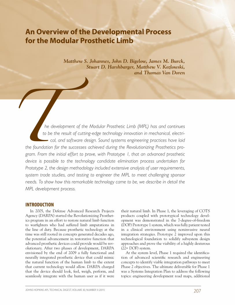
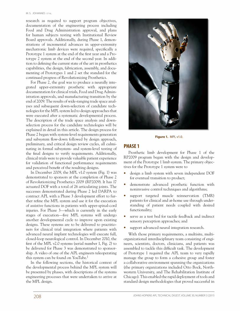
In December 2009, the MPL v1.0 system (Fig. 1) was demonstrated to sponsors at the completion of Phase 2 of Revolutionizing Prosthetics 2009 (RP2009). It has 17 actuated DOF with a total of 26 articulating joints. The successes demonstrated during Phase 2 led DARPA to contract APL with a Phase 3 development effort to fur-ther refine the MPL system and use it for the execution of assistive functions in patients with upper-spinal-cord injuries. For Phase 3—which is currently in the early stages of execution—five MPL systems will undergo another developmental cycle to improve upon existing designs. These systems are to be delivered to practitio-ners for clinical trial integration where patients with advanced neural implant technologies will execute full, closed-loop neurological control. In December 2010, the first of the MPL v2.0 systems (serial number 1, Fig. 2) to be delivered for Phase 3 was demonstrated to sponsor-ship. A video of one of the APL engineers teleoperating this system can be found on YouTube.1
In the following sections, the historical context of the developmental process behind the MPL system will be presented by phases, with descriptions of the systems engineering processes that were undertaken to arrive at the MPL design.
Figure 1. MPL v1.0.
DEVELOPMENTAL PROCESS FOR THE MODULAR PROSTHETIC LIMB
JOHNS HOPKINS APL TECHNICAL DIGEST, VOLUME 30, NUMBER 3 (2011) 209
also assembled additional Prototype 1 units for use by research partners for more advanced neural integration studies. As a result of these efforts, Prototype 1 had a positive impact on the user community, and this impact became evident much earlier than planned during the execution of the RP2009 program.
The Prototype 2 design effort was structured as a risk-reduction activity with the intent being to demonstrate that 22 actuated DOF could indeed be achieved with the appropriate volume, weight, speeds, and forces required of the MPL. The Prototype 2 developmental phase was characterized by three primary objectives:
1. Develop a risk-mitigation approach for the MPL for RP2009
2. Create a mechatronic limb that meets the DARPA requirements to the extent possible
3. Include an avenue for tactile sensory feedback to the patient
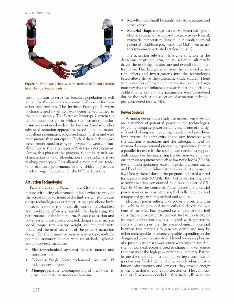
The valuable lessons learned from the engineering development processes and clinical experience gained during the Prototype 1 efforts were captured and incor-porated into the Prototype 2 effort. Additionally, Proto-type 2 efforts supported demonstration of emerging neural control strategies as well as more realistic evaluations of body attachment strategies under realistic accelerations and loads. As with Prototype 1, there were numerous organizations involved in the development of Prototype 2 [primary organizations included New World Associates (now Hunter Defense Technologies), Kinea Design, Otto Bock, Northwestern University, Oak Ridge National Lab-oratory, The Rehabilitation Institute of Chicago, Scuola Superiore Sant’Anna, and Vanderbilt University]. As part of the early system and technology trade studies, it was determined that there were several viable approaches; thus, two Prototype 2 systems were selected for develop-ment (Fig. 4). A key influence on the trade study process was the determination that the program should address the full range of amputation levels—wrist disarticulation, transradial, elbow disarticulation, transhumeral, and full shoulder disarticulation. This decision was ultimately
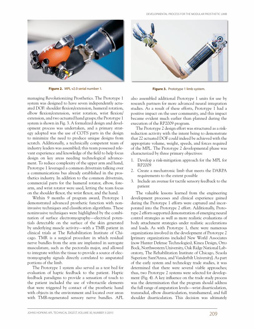
managing Revolutionizing Prosthetics. The Prototype 1 system was designed to have seven independently actu-ated DOF: shoulder flexion/extension, humeral rotation, elbow flexion/extension, wrist rotation, wrist flexion/extension, and two actuated hand grasps; the Prototype 1 system is shown in Fig. 3. A formalized design and devel-opment process was undertaken, and a primary strat-egy adopted was the use of COTS parts in the design to minimize the need to produce unique designs from scratch. Additionally, a technically competent team of industry leaders was assembled; this team possessed rele-vant experience and knowledge of the field to help focus design on key areas needing technological advance-ment. To reduce complexity of the upper arm and hand, Prototype 1 leveraged a common drivetrain talking over a communications bus already established in the pros-thetics industry. In addition to the common drivetrain, commercial parts for the humeral rotator, elbow, fore-arm, and wrist rotator were used, letting the team focus on the shoulder flexor, the wrist flexor, and the hand.
Within 9 months of program award, Prototype 1 demonstrated advanced prosthetic function with non-invasive techniques and classification algorithms. These noninvasive techniques were highlighted by the combi-nation of surface electromyography—electrical poten-tials detectable on the surface of the skin generated by underlying muscle activity—with a TMR patient in clinical trials at The Rehabilitation Institute of Chi-cago. TMR is a surgical procedure in which residual nerve bundles from the arm are implanted in surrogate musculature, such as the pectoralis major, and allowed to integrate within the tissue to provide a source of elec-tromyography signals directly correlated to amputated portions of the limb.
The Prototype 1 system also served as a test bed for evaluation of haptic feedback to the patient. Haptic feedback paradigms to provide a sensation of touch to the patient included the use of vibrotactile elements that were triggered by contact of the prosthetic hand with objects in the environment and located over areas with TMR-regenerated sensory nerve bundles. APL
Figure 2. MPL v2.0 serial number 1. Figure 3. Prototype 1 limb system.
M. S. JOHANNES ET AL.
JOHNS HOPKINS APL TECHNICAL DIGEST, VOLUME 30, NUMBER 3 (2011)210
• Mesofluidics: Small hydraulic actuators, pumps, and servo valves
• Material shape-change actuators: Electrical (piezo-electric ceramics, plastics, and electroactive polymers), magnetic, temperature (bimetallic, nitinol), chemical potential (acid/base polymers), and McKibben actua-tors (pneumatic-actuated artificial muscle)
The actuation subsystem is a core function in the dexterous prosthetic arm, so its selection ultimately drives the resulting architecture and overall system per-formance. The data gathered from the advanced actua-tion efforts and investigations into the technologies listed above drove the systematic trade studies. There were a number of program characteristics such as design maturity risk that influenced the architectural decisions. Additionally, key analytic parameters were considered during the trade study selection of actuation technolo-gies considered for the MPL.
Power SourcesA similar design trade study was undertaken to evalu-
ate a number of potential power source technologies. Providing adequate power for daily use is one of the sig-nificant challenges in designing an advanced prosthetic limb system. As complexity of the arm increases with the addition of actuators and the subsequent need for increased computational processing capabilities, there is a parallel increase in the total power needed to support daily usage. Further impacting the decision were numer-ous sponsor requirements such as low noise levels (50 dB), low vibration signatures, ease of logistical replenishment, and Food and Drug Administration certification capabil-ity. Data gathered during the program indicated a need for approximately 50 W-h (180 J) of power for one day’s activity that was constrained by a mass budget of 0.5–0.75 lb. Over the course of Phase 1, multiple potential power sources such as batteries, fuel cells, engines, and compressed gas were researched and explored.
Electrical power sufficient to power a prosthetic arm is likely to be provided from either fuel-powered sys-tems or batteries. Fuel-powered systems range from fuel cells that use oxidation to convert fuel to electricity to internal combustion engines coupled with generators. Battery chemistries use the electrochemical potential between two materials to generate power and may be either rechargeable or nonrechargeable depending on the design and chemistry involved. Hybrid power supplies are also possible, where a power source with high energy den-sity but low peak power is used to charge a power source that can meet the high peak power requirements. Batter-ies are the traditional method of powering electronics for good reason. With high reliability, well-developed distri-bution infrastructure, and low cost, they provide energy in the form that is required for electronics. The culmina-tion of all research concluded that fuels cells were too
very important to serve the broadest population as well as to make the system more commercially viable for tran-sition opportunities. The Intrinsic Prototype 2 system is characterized by all actuators being self-contained in the hand assembly. The Extrinsic Prototype 2 system is a tendon-based design in which the actuation mecha-nisms are contained within the forearm. Similarly, other advanced actuation approaches, mesofluidics and mono-propellant pneumatics, progressed much further and were more mature than anticipated. Both of these technologies were demonstrated in early prototypes and were continu-ally refined in the early stages of Prototype 2 development. During this phase of the program, the primary task was characterization and risk-reduction trade studies of these working prototypes. This allowed a more realistic trade-off of risk, cost, performance, and reliability to provide a much stronger foundation for the MPL architecture.
Actuation TechnologiesFrom the outset of Phase 1, it was felt there were limi-
tations with using electromechanical devices to provide the actuation powerhouse of the limb system. Many can-didate technologies exist for actuating a prosthetic limb; however, few offer the forces, displacements, velocities, and packaging efficiency suitable for duplicating the performance of the human arm. Because actuation and power systems are closely coupled, design trades such as speed, torque, total energy, weight, volume, and safety influenced the final selection of the primary actuation design. For the primary actuation system type, multiple potential actuation sources were researched, explored, and prototyped, including:
• Electromechanical systems: Electric motors and transmissions
• Cobotics: Single electromechanical drive with 15 independent outputs
• Monopropellant: Decomposition of peroxides to drive pneumatic actuators with steam
Figure 4. Prototype 2 limb systems. Intrinsic (left) and extrinsic (right) hand actuation variants.
DEVELOPMENTAL PROCESS FOR THE MODULAR PROSTHETIC LIMB
JOHNS HOPKINS APL TECHNICAL DIGEST, VOLUME 30, NUMBER 3 (2011) 211
• Cosmesis (shape, volume, appearance, elasticity, durability)
• Function [energy per day, torque, speed, dexterity (DOF), range of motion]
• Cost (development, engineering labor costs, proto-type costs, first cost, life-cycle cost)
• Supportability (reliability, maintainability)• Commercial viability (amputation levels accommo-
dated, transportability, manufacturability)• Operational safety (battery safety, drive power safety,
uncontrolled impact safety, controlled impact safety)
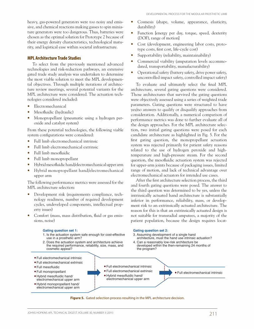
To evaluate and ultimately select the final MPL architecture, several gating questions were considered. Those architectures that survived the gating questions were objectively assessed using a series of weighted trade parameters. Gating questions were structured to have yes/no answers to qualify or disqualify approaches from consideration. Additionally, a numerical comparison of performance metrics was done to further evaluate all of the design approaches. For the MPL architecture selec-tion, two initial gating questions were posed for each candidate architecture as highlighted in Fig. 5. For the first gating question, the monopropellant actuation system was rejected primarily for patient safety reasons related to the use of hydrogen peroxide and high- temperature and high-pressure steam. For the second question, the mesofluidic actuation system was rejected for upper-arm joints because of packaging issues, limited range of motion, and lack of technical advantage over electromechanical actuators for intended use cases.
After the first architecture selection process, the third and fourth gating questions were posed. The answer to the third question was determined to be yes, unless the intrinsically actuated hand architecture is substantially inferior in performance, reliability, mass, or develop-ment risk to an extrinsically actuated architecture. The reason for this is that an extrinsically actuated design is not suitable for transradial amputees, a majority of the patient population, because the design requires locat-
heavy, gas-powered generators were too noisy and emis-sive, and chemical reactions making gasses to spin minia-ture generators were too dangerous. Thus, batteries were chosen as the optimal solution for Prototype 2 because of their energy density characteristics, technological matu-rity, and logistical ease within societal infrastructure.
MPL Architecture Trade StudiesTo select from the previously mentioned advanced
technologies and risk-reduction pathways, an extensive gated trade study analysis was undertaken to determine the most viable solution to meet the MPL developmen-tal objectives. Through multiple iterations of architec-ture review meetings, several potential variants for the MPL architecture were considered. The actuation tech-nologies considered included:
• Electromechanical• Mesofluidic (hydraulic)• Monopropellant (pneumatic using a hydrogen per-
oxide and catalyst system)
From these potential technologies, the following viable system configurations were considered:• Full limb electromechanical intrinsic• Full limb electromechanical extrinsic• Full limb mesofluidic• Full limb monopropellant• Hybrid mesofluidic hand/electromechanical upper arm• Hybrid monopropellant hand/electromechanical
upper arm
The following performance metrics were assessed for the MPL architecture selection:
• Development risk (requirements compliance, tech-nology readiness, number of required development cycles, undeveloped components, intellectual prop-erty issues)
• Comfort (mass, mass distribution, fluid or gas emis-sions, noise)
Gating question set 2:3. Assuming development of a single hand architecture, must the hand use intrinsic actuation?4. Can a reasonably low-risk architecture be developed within the then-remaining 24 months of the program?
Gating question set 1:1. Is the actuation system safe enough for cost-effective use in a prosthetic arm?2. Does the actuation system and architecture achieve the required performance, reliability, size, mass, and cosmetic appeal?
• Full electromechanical intrinsic• Full electromechanical extrinsic• Full mesofluidic• Full monopropellant• Hybrid mesofluidic hand/ electromechanical upper arm• Hybrid monopropellant hand/ electromechanical upper arm
• Full electromechanical intrinsic• Full electromechanical extrinsic• Hybrid mesofluidic hand/ electromechanical upper arm
• Full electromechanical intrinsic
Figure 5. Gated selection process resulting in the MPL architecture decision.
M. S. JOHANNES ET AL.
JOHNS HOPKINS APL TECHNICAL DIGEST, VOLUME 30, NUMBER 3 (2011)212
J Redesign the thumb to have a smaller profile using four actuated DOF
J Iterate common drivetrain design for upper-arm joints to increase torque/efficiency, reduce weight, and increase reliability
• Electrical Systems
J Repackage electronics and sensors and reduce permutations of hand drive motor controllers
J Redesign large motor controller (LMC) used in the wrist and upper-arm joints to improve reliability
J Design and develop a main MPL control board
• Software, Communication, and Control Systems
J Develop the final software architectureJ Validate the impedance control strategyJ Decide upon a communications bus architecture
The design approach for many aspects of the MPL system design was to make the system modular at a number of key interfaces; this served two primary pur-poses. The first was to allow patients with different levels of upper-arm amputations and disarticulation to lever-age the capabilities of the MPL system. The upper arm contains a shoulder with two drives (abduction/adduc-tion and flex/extend), a humeral rotator, an elbow, and the power unit. Depending on the amputation level of a particular patient, all of the joints or a subset can be used. The second purpose for a modular system design was to increase the commonality between subunits of the system to reduce fabrication complexity and increase system interchangeability. The thumb, fingers, and finger abduction/adduction drives are designed as self- contained units with embedded motor controllers con-taining low-level position and velocity control algorithms with dedicated electrical connections to the palm. Addi-tionally, the fingers are designed to attach with common mechanical and electrical connections, so any of the four fingers can be mounted in any location, allowing a fully functional hand to be assembled with up to four two-motor fingers (two actuated DOF) or a simplified, lighter-weight hand to be assembled using four one-motor fingers (one actuated DOF). The palm contains mechanical attachment points and electrical connectors for all four fingers, the thumb, the finger abduction/adduction units, and the wrist. For patients with transradial amputations resulting in a long residual limb, the power and associated processing units can be mounted to the outside of the socket or worn on a belt pack as necessary. The socket represents the subsystem that provides secure attachment of the MPL to the patient.
The allocation of formal design requirements shaped the path forward for the MPL development cycle. The design process started with the formal gathering of customer (DARPA) requirements and the subsequent
ing actuation elements in the forearm. The extrinsically actuated Prototype 2 hand architecture was then elimi-nated from MPL architecture consideration. The fourth and final gating question was posed to the remaining two candidate architectures, and the hybrid limb system of an intrinsically actuated mesofluidic hand and an electromechanical upper arm was eliminated because of development risks such as required main pump develop-ment from scratch, uncertainty of custom piston/cylinder assembly meeting reliability requirements, estimated 8-month effort to determine whether valve technology was viable, and the need for custom electrical design for valve control. Conversely, it was decided that the Proto-type 2 Intrinsic hand was less risky because all key com-ponents were already prototyped (motors, electronics, transmissions) and development iterations had a more straightforward path and lower overall risk. Once a final architecture for the MPL was decided, focus then turned to the design, fabrication, and testing of the MPL system.
PHASE 2Based on the Prototype 2 design and architecture
selection results, the following conclusions were reached:
• MPL development will leverage electromechanical actuation at all joints.
• The hand will be intrinsically actuated, which implies all hand motors reside within the palm and fingers.
J As a result, the hand design path going forward focused on a high-dexterity (15-motor) configu-ration that exceeded DARPA requirements and a lower-cost (9- or 10-motor) variant optimized for clinical use and successful near-term transition.
• The Prototype 2 upper arm and intrinsic hand will be used as starting point for development.
In light of these conclusions, primary challenges remained in developing the MPL. First, reliable integra-tion of mechanical components, electronics, sensors, and batteries remained a huge design challenge. Second, a primary design revision of the mechanical drivetrain design used in the intrinsic hand was needed to improve efficiency and reliability. Finally, the short time frame for development (24 months) required rapid engineering development over multiple design iterations to achieve the desired size, weight, and reliability for the subsystems.
A number of key high-level design decisions based upon the Prototype 1 and 2 developmental cycles, trade study exercises, and testing shaped the primary developmental path going forward for the design of the MPL system.
• Mechanical Systems
J Design a common drivetrain for all hand drives
DEVELOPMENTAL PROCESS FOR THE MODULAR PROSTHETIC LIMB
JOHNS HOPKINS APL TECHNICAL DIGEST, VOLUME 30, NUMBER 3 (2011) 213
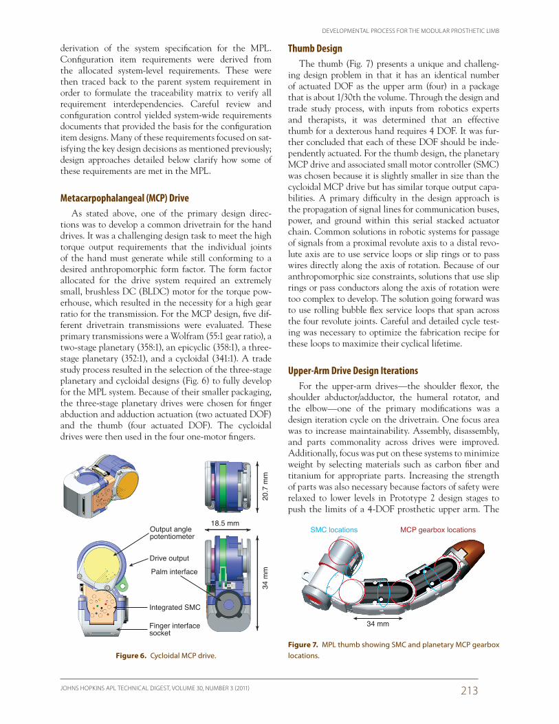
Thumb DesignThe thumb (Fig. 7) presents a unique and challeng-
ing design problem in that it has an identical number of actuated DOF as the upper arm (four) in a package that is about 1/30th the volume. Through the design and trade study process, with inputs from robotics experts and therapists, it was determined that an effective thumb for a dexterous hand requires 4 DOF. It was fur-ther concluded that each of these DOF should be inde-pendently actuated. For the thumb design, the planetary MCP drive and associated small motor controller (SMC) was chosen because it is slightly smaller in size than the cycloidal MCP drive but has similar torque output capa-bilities. A primary difficulty in the design approach is the propagation of signal lines for communication buses, power, and ground within this serial stacked actuator chain. Common solutions in robotic systems for passage of signals from a proximal revolute axis to a distal revo-lute axis are to use service loops or slip rings or to pass wires directly along the axis of rotation. Because of our anthropomorphic size constraints, solutions that use slip rings or pass conductors along the axis of rotation were too complex to develop. The solution going forward was to use rolling bubble flex service loops that span across the four revolute joints. Careful and detailed cycle test-ing was necessary to optimize the fabrication recipe for these loops to maximize their cyclical lifetime.
Upper-Arm Drive Design IterationsFor the upper-arm drives—the shoulder flexor, the
shoulder abductor/adductor, the humeral rotator, and the elbow—one of the primary modifications was a design iteration cycle on the drivetrain. One focus area was to increase maintainability. Assembly, disassembly, and parts commonality across drives were improved. Additionally, focus was put on these systems to minimize weight by selecting materials such as carbon fiber and titanium for appropriate parts. Increasing the strength of parts was also necessary because factors of safety were relaxed to lower levels in Prototype 2 design stages to push the limits of a 4-DOF prosthetic upper arm. The
derivation of the system specification for the MPL. Configuration item requirements were derived from the allocated system-level requirements. These were then traced back to the parent system requirement in order to formulate the traceability matrix to verify all requirement interdependencies. Careful review and configuration control yielded system-wide requirements documents that provided the basis for the configuration item designs. Many of these requirements focused on sat-isfying the key design decisions as mentioned previously; design approaches detailed below clarify how some of these requirements are met in the MPL.
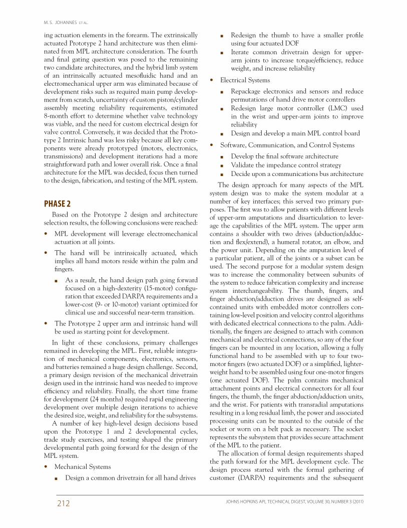
Metacarpophalangeal (MCP) DriveAs stated above, one of the primary design direc-
tions was to develop a common drivetrain for the hand drives. It was a challenging design task to meet the high torque output requirements that the individual joints of the hand must generate while still conforming to a desired anthropomorphic form factor. The form factor allocated for the drive system required an extremely small, brushless DC (BLDC) motor for the torque pow-erhouse, which resulted in the necessity for a high gear ratio for the transmission. For the MCP design, five dif-ferent drivetrain transmissions were evaluated. These primary transmissions were a Wolfram (55:1 gear ratio), a two-stage planetary (358:1), an epicyclic (358:1), a three-stage planetary (352:1), and a cycloidal (341:1). A trade study process resulted in the selection of the three-stage planetary and cycloidal designs (Fig. 6) to fully develop for the MPL system. Because of their smaller packaging, the three-stage planetary drives were chosen for finger abduction and adduction actuation (two actuated DOF) and the thumb (four actuated DOF). The cycloidal drives were then used in the four one-motor fingers.
18.5 mm
Palm interface
Integrated SMC
Drive output
Output anglepotentiometer
Finger interfacesocket
20.7
mm
34 m
m
Figure 6. Cycloidal MCP drive.
34 mm
SMC locations MCP gearbox locations
Figure 7. MPL thumb showing SMC and planetary MCP gearbox locations.
M. S. JOHANNES ET AL.
JOHNS HOPKINS APL TECHNICAL DIGEST, VOLUME 30, NUMBER 3 (2011)214
LMC DesignTo further reduce part count and design complexity,
it was important to design motor controllers that were usable at multiple joint locations. The intent of the iter-ated design of the LMC was to provide a circuit design that could be leveraged at the four joints of the upper arm and the three joints at the wrist. The LMC provides for BLDC motor commutation, sensor signal sampling, and communication with the LC via a controller area network (CAN) bus. The LMC is designed to monitor the local joint temperature, torque, position, current, and rotor position sensors for motor commutation. Custom schematic design and multilayer board fabrication enabled integration directly within the drive module. This allowed the drives to be designed as single inte-grated motor and controller packages, reducing overall mechanical profile and maximizing performance. Each LMC uses an advanced reduced instruction set computer (ARM)-based processor for its microcomputing needs.
LC DesignTo facilitate communications and data handling from
the various processing nodes of the MPL system, an over-arching controller was necessary. The LC processes and distributes incoming high-level intent command com-munications with the master source of command data, whether it is from conventional prosthetic inputs (elec-tromyography signals, switches, etc.), advanced neural implant-based sources, joint-level motion tracking inputs from a teleoperator, or simple command line inputs. The LC has two individually populated printed circuit boards approximately 1 square inch in area and is cen-trally located within the palm of the hand. The palm was chosen as the location because of the desire to accommo-date even the longest of residual limb amputees, whom would only require a functional hand as their prosthetic. A Texas Instruments Open Multimedia Application Plat-form (OMAP) processor with integrated memory as the main computing node and a CAN bus communications interface are mounted on the first board. The other board houses a field-programmable gate array charged with data distribution to the RS-485 communications buses for the SMCs of the fingers, thumb, and sensor nodes.
Software SystemsThe MPL software systems consist of code running
on the LC, SMCs, LMCs, and FTSNs. The LC is the main processor of the limb and is responsible for receiv-ing limb control commands, running high-level control algorithms, and communicating with the LMCs at 50 Hz, the SMCs at 200 Hz, and the FTSNs at 200 Hz. It also provides the gateway for troubleshooting, diagnostics, and configuration of the limb system. The LMC software is responsible for providing closed-loop position, velocity,
gear train was optimized to minimize sound output by changing from a toothed planetary reduction stage to a friction planetary reduction stage. Further design modi-fications increased the active torque output capabilities to 60 N·m by eliminating sources of friction that were robbing efficiency.
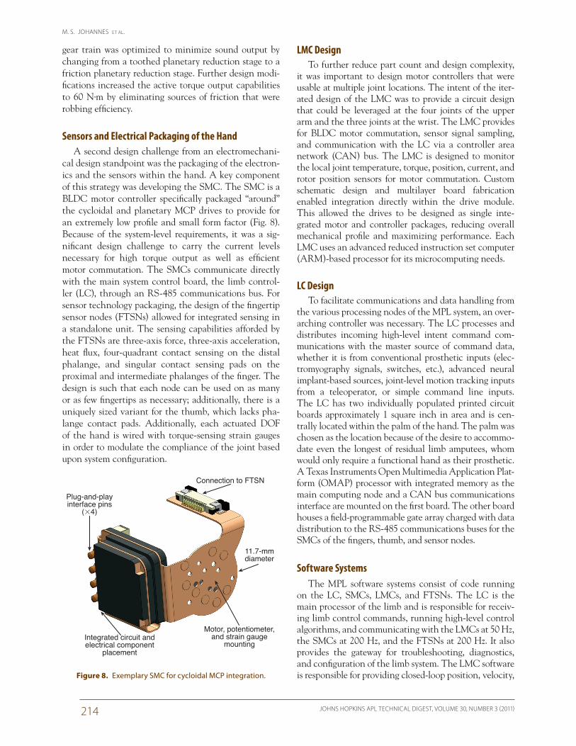
Sensors and Electrical Packaging of the HandA second design challenge from an electromechani-
cal design standpoint was the packaging of the electron-ics and the sensors within the hand. A key component of this strategy was developing the SMC. The SMC is a BLDC motor controller specifically packaged “around” the cycloidal and planetary MCP drives to provide for an extremely low profile and small form factor (Fig. 8). Because of the system-level requirements, it was a sig-nificant design challenge to carry the current levels necessary for high torque output as well as efficient motor commutation. The SMCs communicate directly with the main system control board, the limb control-ler (LC), through an RS-485 communications bus. For sensor technology packaging, the design of the fingertip sensor nodes (FTSNs) allowed for integrated sensing in a standalone unit. The sensing capabilities afforded by the FTSNs are three-axis force, three-axis acceleration, heat flux, four-quadrant contact sensing on the distal phalange, and singular contact sensing pads on the proximal and intermediate phalanges of the finger. The design is such that each node can be used on as many or as few fingertips as necessary; additionally, there is a uniquely sized variant for the thumb, which lacks pha-lange contact pads. Additionally, each actuated DOF of the hand is wired with torque-sensing strain gauges in order to modulate the compliance of the joint based upon system configuration.
Connection to FTSN
11.7-mmdiameter
Plug-and-playinterface pins
(�4)
Motor, potentiometer,and strain gauge
mountingIntegrated circuit andelectrical component
placement
Figure 8. Exemplary SMC for cycloidal MCP integration.
DEVELOPMENTAL PROCESS FOR THE MODULAR PROSTHETIC LIMB
JOHNS HOPKINS APL TECHNICAL DIGEST, VOLUME 30, NUMBER 3 (2011) 215
to deterministically deliver messages across the nodes. An additional advantage is that it consists of only two wires, simplifying wire routing and interconnect design. The LC also communicates with up to 10 SMCs and up to 5 FTSNs using an RS-485 bus operating at 500 kbps. This bus architecture uses a 9-bit universal asynchro-nous receiver/transmitter interface where 8 bits are used for data and the ninth bit is used to specify the start of a new message. This is especially useful for resynchroniz-ing messages in the event of data loss. The advantages of using this bus architecture for the hand are high data rates; multidrop configuration, which minimizes the number of wires needed; and differential communica-tion, providing better immunity against electrical noise.
As mentioned earlier, MPL v1.0 was the culmination of an extensive research, design, development, and inte-gration effort spanning more than 4 years and countless man hours. Through trade study analysis, optimization, and design complexity reduction, MPL v1.0 exhibits 17 actuated DOF, or specific points in the system where joint level commands can be set to enact motion. It has 26 total DOF, which are defined here as individual axes of rotation. These quantities differ because some joints are kinematically coupled by design intent to minimize complexity. In the MPL system, there are four upper-arm drives—shoulder flexion/extension and abduction/adduction, humeral rotation, and elbow flexion/exten-sion. The wrist has three drives—rotation, abduction/adduction, and flexion/extension. The thumb has four drives—carpometacarpal abduction/adduction, carpo-metacarpal flexion/extension, MCP flexion/extension, and interphalangeal flexion/extension. Each of the fin-gers has one motor drive at the MCP joint to articu-late the three kinematically coupled joints of the finger differential linkage mechanism. Finally, there are two drives for finger abduction/adduction—one that moves the index finger radially and another that moves the coupled ring and little fingers medially.
PHASE 3Currently, Revolutionizing Prosthetics Phase 3 (RP3)
is under way. The ultimate goal is use the MPL in con-junction with advanced neural implant technology to restore functionality to upper-spinal-cord injury patients who have lost control of their natural limbs. In this con-text, the MPL system will be used as an assistive robotic device that will enable the user to perform specific activities of daily living through direct brain control. Additionally, specific MPL Phase 3 efforts will focus on the continued refinement of system technologies by incrementing designs, improving reliability, increasing simplicity, leveraging commonality among subsystems, maximizing performance, and evolving software and controls algorithms. MPL systems will be distributed to clinical partners for use in neural-based research and
and torque control of the motors in the upper arm and wrist joints of the MPL. The SMC software is respon-sible for actuating the finger and thumb joints of the MPL hand by running closed-loop position and veloc-ity control of a BLDC motor. The SMC software is also responsible for interfacing with several contact sensors found throughout the palm for tactile feedback. As men-tioned previously, the FTSNs are found on the fingertips of the hand and consist of a suite of sensors that obtain information from the environment. The FTSN software samples the sensors at a rate of 400 Hz and reports the data to the LC at a rate of 200 Hz for processing.
Impedance Control StrategyThe design of the overall control architecture was
intended to provide as much flexibility to the patient for controlling the limb without introducing discontinu-ous topological changes and the corresponding issues associated with resetting initial conditions. One of the primary tenets was to develop an impedance control strategy in which the limb would respond with a pre-defined stiffness, damping, and inertia at each joint. A fundamental single structure called the individual joint/link controller serves as the basic building block for this design. The individual joint/link controller is based upon an impedance control approach where torque and motion feedback is used to alter the dynamics of the links and actuators such that a desired impedance relationship between externally applied torque and joint motion is realized. This programmable impedance pro-vides a more compliant and human-like performance. Parameters can be adjusted within all control modes to modulate the impedance of selected joints. Such imped-ance modulation, for example, allows the limb to better mimic the compliance of a natural limb. Due to band-width and processor limitations on the SMCs, there is only a fixed impedance algorithm that is tuned to pro-vide rapid low-magnitude responses to physical shocks. An outer impedance modulation algorithm resides on the LC to provide the desired dynamic behavior.
Bus ArchitectureSeveral bus architectures, including the Axon-Bus
used for Prototype 1, were compared through a trade study including other candidates such as Ethernet, Fibre Channel, Universal Serial Bus, IEEE 1394, the CAN bus, and others. The CAN bus was deemed most suit-able because of its relatively high bandwidth, reliabil-ity, commercial availability and support, low power, and low infrastructure cost. The CAN bus operates at 1 Mbps and is used to connect the LC, LMCs, and a host computer that sends control commands to the limb. Although the CAN bus protocol is primarily used in the auto industry, it was selected for the MPL because of its robustness, especially under noisy conditions, and ability
M. S. JOHANNES ET AL.
JOHNS HOPKINS APL TECHNICAL DIGEST, VOLUME 30, NUMBER 3 (2011)216
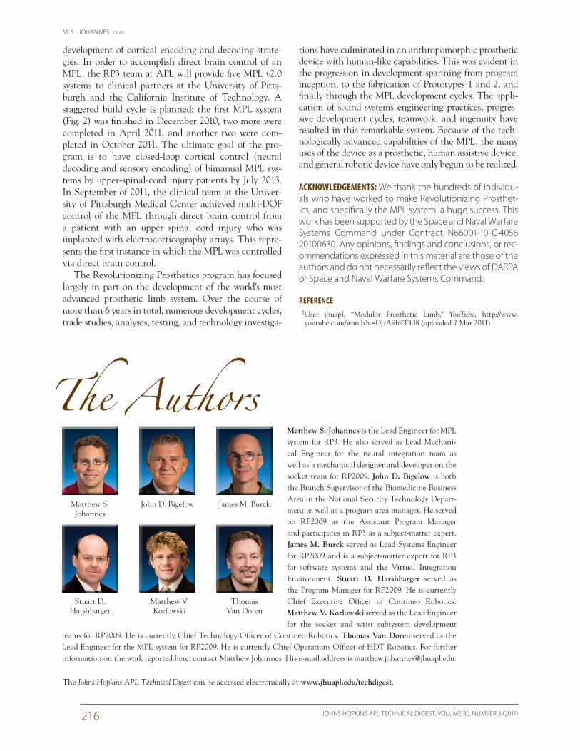
Matthew S. Johannes is the Lead Engineer for MPL system for RP3. He also served as Lead Mechani-cal Engineer for the neural integration team as well as a mechanical designer and developer on the socket team for RP2009. John D. Bigelow is both the Branch Supervisor of the Biomedicine Business Area in the National Security Technology Depart-ment as well as a program area manager. He served on RP2009 as the Assistant Program Manager and participates in RP3 as a subject-matter expert. James M. Burck served as Lead Systems Engineer for RP2009 and is a subject-matter expert for RP3 for software systems and the Virtual Integration Environment. Stuart D. Harshbarger served as the Program Manager for RP2009. He is currently Chief Executive Officer of Contineo Robotics. Matthew V. Kozlowski served as the Lead Engineer for the socket and wrist subsystem development
teams for RP2009. He is currently Chief Technology Officer of Contineo Robotics. Thomas Van Doren served as the Lead Engineer for the MPL system for RP2009. He is currently Chief Operations Officer of HDT Robotics. For further information on the work reported here, contact Matthew Johannes. His e-mail address is [email protected].
tions have culminated in an anthropomorphic prosthetic device with human-like capabilities. This was evident in the progression in development spanning from program inception, to the fabrication of Prototypes 1 and 2, and finally through the MPL development cycles. The appli-cation of sound systems engineering practices, progres-sive development cycles, teamwork, and ingenuity have resulted in this remarkable system. Because of the tech-nologically advanced capabilities of the MPL, the many uses of the device as a prosthetic, human assistive device, and general robotic device have only begun to be realized.
ACKNOWLEDGEMENTS: We thank the hundreds of individu-als who have worked to make Revolutionizing Prosthet-ics, and specifically the MPL system, a huge success. This work has been supported by the Space and Naval Warfare Systems Command under Contract N66001-10-C-4056 20100630. Any opinions, findings and conclusions, or rec-ommendations expressed in this material are those of the authors and do not necessarily reflect the views of DARPA or Space and Naval Warfare Systems Command.
REFERENCE 1User jhuapl, “Modular Prosthetic Limb,” YouTube, http://www.
youtube.com/watch?v=DjzA9b9T3d8 (uploaded 7 Mar 2011).
development of cortical encoding and decoding strate-gies. In order to accomplish direct brain control of an MPL, the RP3 team at APL will provide five MPL v2.0 systems to clinical partners at the University of Pitts-burgh and the California Institute of Technology. A staggered build cycle is planned; the first MPL system (Fig. 2) was finished in December 2010, two more were completed in April 2011, and another two were com-pleted in October 2011. The ultimate goal of the pro-gram is to have closed-loop cortical control (neural decoding and sensory encoding) of bimanual MPL sys-tems by upper-spinal-cord injury patients by July 2013. In September of 2011, the clinical team at the Univer-sity of Pittsburgh Medical Center achieved multi-DOF control of the MPL through direct brain control from a patient with an upper spinal cord injury who was implanted with electrocorticography arrays. This repre-sents the first instance in which the MPL was controlled via direct brain control.
The Revolutionizing Prosthetics program has focused largely in part on the development of the world’s most advanced prosthetic limb system. Over the course of more than 6 years in total, numerous development cycles, trade studies, analyses, testing, and technology investiga-
The Johns Hopkins APL Technical Digest can be accessed electronically at www.jhuapl.edu/techdigest.
The Authors
John D. BigelowMatthew S. Johannes
James M. Burck
Stuart D. Harshbarger
Thomas Van Doren
Matthew V. Kozlowski