an overview of the lightning launch commit criteria · 2005-11-07 · 1.1 a survey of the lightning...
TRANSCRIPT
1.1 A Survey Of The Lightning Launch Commit Criteria
William P. Roeder and Todd M. McNamara 45th Weather Squadron,
Patrick AFB, FL
1. 45 WS MISSION
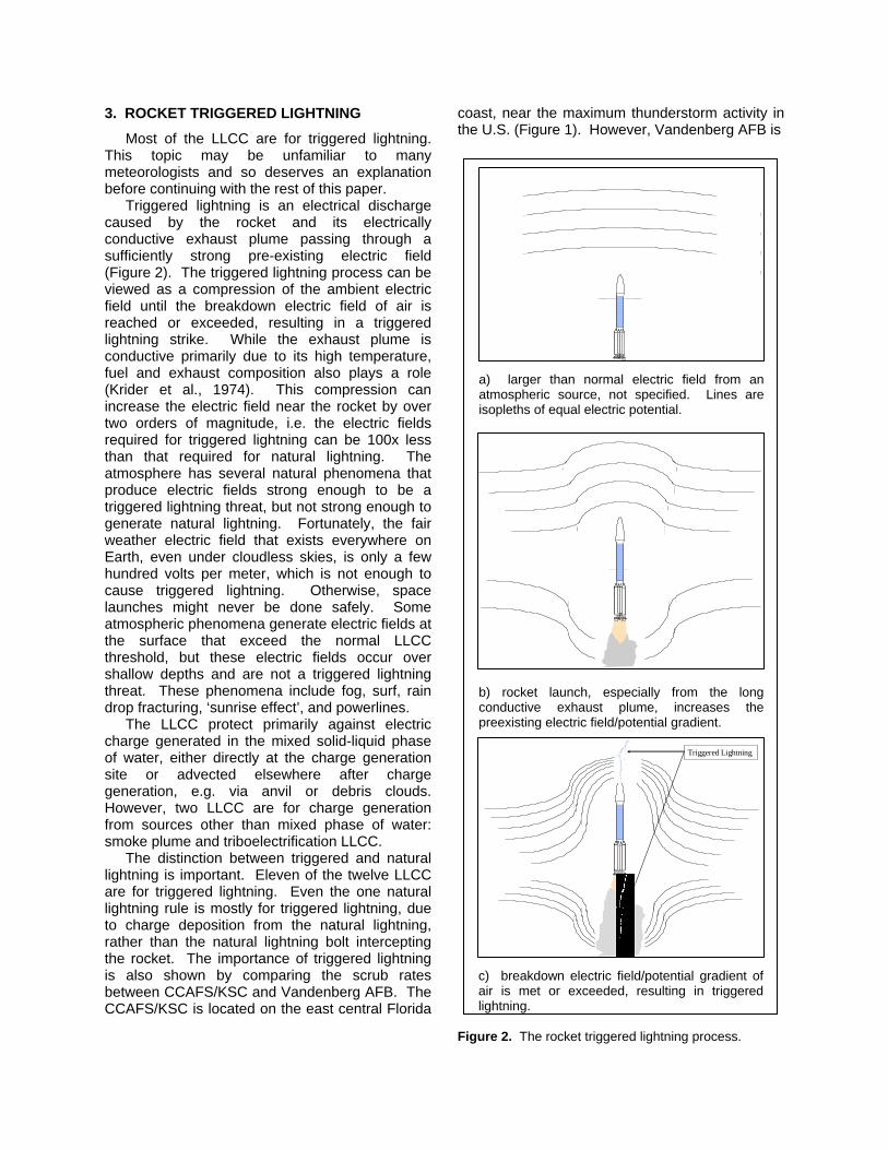
The 45th Weather Squadron (45 WS) provides comprehensive weather services to America’s space program at Cape Canaveral Air Force Station (CCAFS) and NASA’s Kennedy Space Center (KSC) (Harms et al., 1999). These services include weather support for pre-launch, launch, post-launch, routine weather forecast, 24/7 watches/warnings, flight briefings, and special missions. A major part of the 45 WS support to launch is evaluating and forecasting the Lightning Launch Commit Criteria (LLCC) (Roeder et al., 1999) and User Launch Commit Criteria (Boyd et al., 1995). The LLCC protect against natural and rocket triggered lightning strikes to the in-flight rocket. The User Launch Commit Criteria include low level winds so the rocket doesn’t topple or get blown back into the launch pad during launch, and ceiling and visibility so the ascending rocket can be tracked by camera to ensure it is on the correct trajectory. Launch customers include the DoD, NASA, and commercial customers for approximately 30 launches per year. The launch vehicles supported recently include Titan, Atlas, Delta, Athena, Pegasus, and Space Shuttle space launch vehicles, and Trident ballistic missiles.
The 45 WS also provides weather information to other offices that evaluate and forecast other Launch Commit Criteria on weather impacts. These other Launch Commit Criteria include aerodynamic loading on in-flight rockets from upper winds (Boyd et al., 1997) and Range Safety support (Boyd et al., 2006). Weather impacts Range Safety decisions on toxic dispersion (Boyd et al., 2002), acoustic overpressure from exploding rockets (Boyd et al., 2000), and debris fallout (Boyd et al., 1999). All this takes place on the coast of east central Florida, which is located near the ‘Thunderstorm Capital’ of the U.S. (Figure 1).
Figure 1. Average cloud-to-ground lighting flash density (flashes/km2•year) for the CONUS (1989–1993), corrected for detection efficiency. Data are from the National Lightning Detection Network. Figure provided by Dr. Richard Orville, Texas A&M University.
2. INTRODUCTION TO THE LIGHTNING LAUNCH COMMIT CRITERIA
The LLCC are a set of rules to avoid natural and rocket triggered lightning strikes to in-flight rockets. Weather is the single largest source of launch delays and scrubs and the LLCC are one of the largest sources of weather impacts. The LLCC have caused nearly 5% of the launches from CCAFS/KSC to scrub and delayed 35% of the launches (Hazen et al., 1995). The LLCC are a set of 12 rules used to avoid the lightning threat to launches from CCAFS/KSC. The cost of a scrub varies from $150,000 to over $1,000,000 depending on launch vehicle. Other impacts include possible delays in future launch schedules, and the human costs of repeated stressful launch attempts. The principles of the LLCC are also used in the Flight Rules to avoid lightning threats to landing Space Shuttles. Flight weather support to the Space Shuttle is provided by the National Weather Service Spaceflight Meteorology Group (Brody, 1997). Corresponding Author: William P. Roeder, 45 WS/SYR,
1201 E. H. White II St., MS 7302, Patrick AFB, FL 32923-3238, [email protected]
3. ROCKET TRIGGERED LIGHTNING
Most of the LLCC are for triggered lightning. This topic may be unfamiliar to many meteorologists and so deserves an explanation before continuing with the rest of this paper.
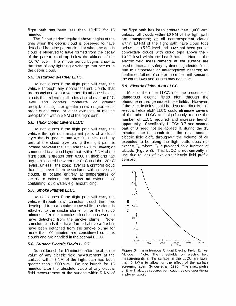
Triggered lightning is an electrical discharge caused by the rocket and its electrically conductive exhaust plume passing through a sufficiently strong pre-existing electric field (Figure 2). The triggered lightning process can be viewed as a compression of the ambient electric field until the breakdown electric field of air is reached or exceeded, resulting in a triggered lightning strike. While the exhaust plume is conductive primarily due to its high temperature, fuel and exhaust composition also plays a role (Krider et al., 1974). This compression can increase the electric field near the rocket by over two orders of magnitude, i.e. the electric fields required for triggered lightning can be 100x less than that required for natural lightning. The atmosphere has several natural phenomena that produce electric fields strong enough to be a triggered lightning threat, but not strong enough to generate natural lightning. Fortunately, the fair weather electric field that exists everywhere on Earth, even under cloudless skies, is only a few hundred volts per meter, which is not enough to cause triggered lightning. Otherwise, space launches might never be done safely. Some atmospheric phenomena generate electric fields at the surface that exceed the normal LLCC threshold, but these electric fields occur over shallow depths and are not a triggered lightning threat. These phenomena include fog, surf, rain drop fracturing, ‘sunrise effect’, and powerlines.
The LLCC protect primarily against electric charge generated in the mixed solid-liquid phase of water, either directly at the charge generation site or advected elsewhere after charge generation, e.g. via anvil or debris clouds. However, two LLCC are for charge generation from sources other than mixed phase of water: smoke plume and triboelectrification LLCC.
The distinction between triggered and natural lightning is important. Eleven of the twelve LLCC are for triggered lightning. Even the one natural lightning rule is mostly for triggered lightning, due to charge deposition from the natural lightning, rather than the natural lightning bolt intercepting the rocket. The importance of triggered lightning is also shown by comparing the scrub rates between CCAFS/KSC and Vandenberg AFB. The CCAFS/KSC is located on the east central Florida
coast, near the maximum thunderstorm activity in the U.S. (Figure 1). However, Vandenberg AFB is
a) larger than normal electric field from an atmospheric source, not specified. Lines are isopleths of equal electric potential.
b) rocket launch, especially from the long conductive exhaust plume, increases the preexisting electric field/potential gradient.
Triggered Lightning
c) breakdown electric field/potential gradient of air is met or exceeded, resulting in triggered lightning.
Figure 2. The rocket triggered lightning process.

on the central California coast, near the minimum thunderstorm activity in the U.S. Despite this wide difference in natural lightning climatology, Vandenberg AFB has a LLCC scrub rate of 5.4% (Desordi, 1999), which is actually slightly higher than the CCAFS/KSC scrub rate of 4.7% (Maier, 1999). These scrub rates were prior to the large changes to the LLCC in 1998. 4. HISTORY OF THE LIGHTNING LAUNCH COMMIT CRITERIA
The LLCC have undergone numerous changes since the 1960s. These changes were driven by operational incidents, scientific improvements, or new weather sensors. The LLCC are in a process of continuous incremental improvement and more changes are expected in the future.
4.1. Apollo-12 (1969)
The danger of rocket triggered lightning to large rockets was first recognized when Apollo-12 suffered two lightning strikes during its launch in 1969. Fortunately, the mission was completed safely, although the rocket required some in-flight maintenance. Prior to Apollo-12 the only LLCC was to avoid flying through cumulonimbus or thunderstorm clouds (Poniatowski, 1987). After Apollo-12, the first set of LLCC resembling the modern rules was created. These rules recognized that large rockets could trigger lightning under conditions that would not generate natural lightning and prohibited launch when those phenomena were present.
4.2. Special Weather Sensors (1973-1975)
NASA next used several special weather sensors during 1973-1975 to help launch high-visibility and/or short-window missions such as Skylab, Apollo-Soyez, and Viking. Some of the special sensors were later implemented into routine operations, including the Lightning Detection And Ranging system that detects all types of lightning and the Launch Pad Lightning Warning System that detects electric fields at the surface. Both of the systems, among others, are discussed in the ‘Weather Systems’ section below. Other special weather sensors were used at that time but not institutionalized, e.g. an X-band weather radar and airborne field mills (Nanevicz et al., 1988). Even though those sensors were not implemented into routine operations, their data proved useful in subsequent LLCC changes.
4.3. Atlas/Centaur-67 (1987)
A possible triggered lightning strike occurred to Atlas-38 in 1976. The only impact was degraded telemetry for about 30 seconds—the mission completed successfully. This event apparently was not investigated deeply from the triggered lightning perspective. No changes were made to the LLCC as a result of this event.
The next major event in the LLCC evolution was the 1987 Atlas/Centaur-67 (AC-67) accident. The AC-67 caused a triggered lightning strike (Figure 3), which disrupted the vehicle guidance electronics and caused an erroneous steer command (Busse, 1987). As the rocket turned sideways, aerodynamic loading caused it to begin breaking-up. Range Safety then sent a telemetry destruction command to ensure the debris crashed in allowable areas and would not threaten civilian populations.
Several studies (Heritage, 1988), and several working groups, produced many LLCC recommendations after the AC-67 accident. As a result of all these competing, and sometimes disparate LLCC recommendations, the 45 WS and NASA Headquarters formed the Peer Review Committee (now Lightning Advisory Panel (LAP)) to advise the USAF and NASA on LLCC issues. This led to a major revision of the LLCC in 1988 (Aerospace, 1988). Since AC-67, there have been no triggered lightning strikes to rockets launched using the modern LLCC. Figure 3. Triggered lightning strike to AC-67 in 1987. The lightning followed the exhaust plume to the ground.

4.4. Airborne Field Mill Experiment-1, Phase-1 (1993-1994)
The third major change to the LLCC was driven by the NASA sponsored airborne field mill experiments during 1990-1992, which led to upgraded LLCC in 1993-1994. The most significant change allowed flight through cumulus clouds with tops up to -5°C; the previous limit was +5°C. Another change allowed launch when the surface electric field mills were above the previous limit of > 1,000 V/m. Launch up to < 1,500 V/m was allowed, but only under specific documented benign phenomena. However, no documented benign phenomena were specified until 1996. Finally, several minor ambiguities in the LLCC were resolved.
4.5. Balloon Field Mill Experiment (1996)
Throughout the years, the 45 WS had occasionally noticed elevated electric fields at the surface that exceeded the LLCC thresholds, even though no significant clouds were in the area. These tended to happen during summer, just after sunrise, and dissipated within a few hours. The space launch community always wanted to explore this ‘sunrise effect’ but competing higher priority requirements precluded that investigation, especially since it usually affected only one surface field mill at a time, suggesting that the phenomenon occurred over too shallow a depth to be a triggered lightning threat. Then during early summer 1996, a ‘sunrise effect’ threatened to scrub a Space Shuttle launch. Although that ‘sunrise effect’ dissipated and the launch was completed on time, it raised the priority of interest. As a result, NASA funded a Balloon Borne Field Mill experiment to investigate the phenomenon later that summer (Marshall et al., 1999). This experiment confirmed that the ‘sunrise effect’ was very shallow in depth and was not a triggered lightning threat. The ‘sunrise effect’ became the first “documented benign phenomena” allowing launch with field mills up to 1,500 V/m, as discussed in section 4.4. At that time, other documented benign phenomena were also added, including shallow ground fog and smoke. The surf effect was also considered, but not officially added since surface electric fields were never observed to exceed the LLCC threshold under heavy surf, even with nearly 20 foot swells from hurricanes. These field mill LLCC exemptions for specific phenomena were later changed to a general exemption, regardless of phenomena, from +1,000 V/m to just under +1,500 V/m, if all clouds within 10 NM are transparent or have tops below
+5°C and haven’t been part of clouds with tops above -10°C within 3 hours. Clouds not meeting those requirements are not generating electrical charge, or cannot store previously generated electric charge, so any other phenomena causing the higher electric fields must be shallow and thus are not a triggered lightning threat.
4.6. Wild Fire Near Western Range (1996)
A large wild fire occurred near the Western Range at Vandenberg AFB around the same time the Balloon Borne Field Mill experiment results were being incorporated into the LLCC. Given anecdotal reports of lightning from pyrocumulus, the Western Range asked if a LLCC was needed for these conditions. This led to smoke being listed as a documented benign phenomenon, as mentioned in section 4.5. It also led to a new smoke plume LLCC. In retrospect, this LLCC might be better named as pyrocumulus LLCC.
4.7. Airborne Field Mill Experiment-1, Phase-2 (1998)
Another major revision to the LLCC occurred in 1998. These changes were based on follow-on results from the 1990-1992 airborne field mill experiment and operational feedback from 45 WS on the LLCC. Significant changes for improved safe launch availability in the 1998 LLCC include: increased use of surface electric field mills, increased use of cloud transparency, and relaxation for anvil cloud restrictions under some conditions. In addition, the LLCC were restructured and reworded for improved operational usability and easier training.
4.8. Kodiak Space Launch Complex (2001)
The first space launch from the Kodiak Space Launch Complex on Kodiak Island, AK was in 2001 (Sardonia and Madura, 2002). The weather infrastructure for this launch facility was designed and implemented from 1998-2001. Part of that process was a surface electric field mill study by Dr. Krider of the University of Arizona. This led to a LLCC for orographically driven cumulus clouds that is less restrictive than the other cumulus LLCC under certain surface electric field mill conditions. In addition, snow and graupel were added to the ‘disturbed weather’ LLCC.
4.9. FAA Commercial Spaceports (2003)
The FAA began regulatory authority for the emerging development of commercial spaceports in the U.S. One of the issues was use of the LLCC. The LLCC were rewritten and reformatted

into a new format that was mutually agreeable to the FAA and both the Air Force and NASA. These rewritten LLCC were published in an Air Force Space Command Instruction in the summer of 2003. This was purely an administration change to reword the LLCC for upcoming commercial spaceports under FAA regulation and to involve the FAA in future LLCC changes. The content and interpretation of the LLCC were not changed.
4.10. Airborne Field Mill Experiment-2, Phase-1 (2005)
The space launch community decided to improve the LLCC with another Airborne Field Mill experiment (Merceret and Christian, 2000). This initiative improved upon the original experiment by adding cloud physics sensors and by having a theoretical cloud electric discharge model as a verification goal. In addition, the experiment was operationally focused on the two LLCC that caused the most operational violations, the violations that generated the most inquiries from the launch customers, and those that likely had the most room for improved launch opportunity. The LLCC for anvil clouds and stratiform thick clouds were selected as the best targets for improvement. The climatologically best times to sample these two phenomena were chosen and data collections were conducted with a weather research aircraft that included electric field mills and cloud physics sensors.
Data were collected during three periods: summer 2000, winter 2001, and summer 2001. These data were combined with the dense network of weather sensors routinely used at the CCAFS/KSC (Roeder et al., 2003), especially the WSR-74C/IRIS radar (McNamara et al., 2005). The data were extensively analyzed from 2001 to 2005.
Two LLCC changes have come from this second airborne fieldmill experiment. The analysis team discovered that the radar definition of 10 dBZ for cloud edge in the LLCC was inadequate. Electric fields with the potential for rocket triggered lightning were detected at reflectivities approaching 5 dBZ. The radar cloud edge definition was immediately changed in 2003 to 0 dBZ for space launch safety. The difference between 5 dBZ and 0 dBZ allows for a margin of safety. The 0 dBZ limit for optical transparency was reinforced later by an unrelated study by the Applied Meteorology Unit on radar products versus cloud transparency (Merceret at al., 2006a).
The second LLCC improvement from the second airborne field mill experiment was a new
rule for anvil clouds that was implemented during the summer of 2005. This new anvil rule allows for closer approach to and through anvil clouds if a new radar metric is satisfied. This new metric is the Volume Average Height Integrated Radar Reflectivity (VAHIRR). A full description of the VAHIRR anvil LLCC is provided by Merceret et al. (2006b).
The VAHIRR anvil LLCC will provide an estimated average improvement in launch opportunity of 30% under anvil cloud conditions without compromising safety and an up to 800% increase in launch opportunity under some extreme anvil conditions. The new VAHIRR-based anvil LLCC should provide an average cost savings of $75,000/year by avoiding needless launch scrubs, considering the frequency of anvil cloud impacts on launch, the costs of launch scrubs, and future launch schedule at CCAFS/KSC.
Unfortunately, VAHIRR is not a product currently generated by any of the operational range radar systems including the WSR-88D used at most American ranges and the WSR-74C used for CCAFS/KSC. However, efforts are currently underway to provide VAHIRR capability in both these radar systems. Fortunately, there is an immediately available work-around that provides some of the VAHIRR capability. 5. CURRENT LLCC
The current LLCC (Table 1) are a set of 12 rules used to avoid the threat of natural and triggered lightning to launches by the Air Force or NASA. These LLCC are complex and very atypical within operational meteorology. If a LLCC is violated during the launch window, then the launch is scrubbed or delayed, depending on time remaining in the launch window. The same LLCC are used for all launch vehicles from CCAFS/KSC and Vandenberg AFB, except for Trident ballistic missile test launches from CCAFS, which have different operational requirements. A complete description of the 12 LLCC follows.
5.1. Lightning LLCC
Do not launch for 30 minutes after any type of lightning occurs in a thunderstorm if the flight path will carry the vehicle within 10 NM of that thunderstorm. Do not launch for 30 minutes after any type of lightning occurs within 10 NM of the flight path, unless: the cloud that produced the lightning is not within 10 NM of the flight path; and there is at least one working field mill within 5 NM of each such lightning flash; and the absolute

values of all electric field measurements at the surface within 5 NM of the flight path and at the mill(s) within 5 NM of the lightning flashes have been less than 1,000 V/m for 15 minutes. Notes: Anvil clouds are covered in the third LLCC; if a cumulus cloud remains 30 minutes after the last lightning occurs in a thunderstorm, then the second LLCC applies.
Table 1. List of LLCC. These numbers will be used elsewhere in this paper to refer to individual LLCC.
LLCC
1. Lightning
2. Cumulus Clouds
3. Anvil Clouds a) Attached Anvil b) Detached Anvil
4. Debris Clouds
5. Disturbed Weather (moderate precipitation, bright band, other signs of supercooled water)
6. Thick Cloud Layers
7. Smoke Plumes
8. Surface Electric Fields
9. Electric Fields Aloft (not in use, due to lack of electric field profiles)
10. Triboelectrification
11. “Good Sense” Rule (suspected triggered lightning threat, not explicitly listed in other LLCC)
12. Orographic Cumulus
5.2. Cumulus Clouds LLCC
Do not launch if the flight path will carry the vehicle within 10 NM of any cumulus cloud with its cloud top higher than the -20 °C level. Do not launch if the flight path will carry the vehicle within 5 NM of any cumulus cloud with its cloud top higher than the -10 °C level. Do not launch if the flight path will carry the vehicle through any cumulus cloud with its cloud top higher than the -5 °C level. Do not launch if the flight path will carry the vehicle through any cumulus cloud with its cloud top between the +5 °C and -5 °C levels unless: the cloud is not producing precipitation; and the horizontal distance from the center of the cloud top to at least one working field mill is less than 2 NM; and all electric field measurements at the surface within 5 NM of the flight path and at the specified mill(s) have been between -100 V/m and +500 V/m for 15 minutes. Note: these
cumulus clouds do not include altocumulus, cirrocumulus, or stratocumulus.
5.3. Anvil Clouds LLCC
The anvil cloud LLCC has two main sections: attached and detached anvil. The anvil cloud LLCC was significantly modified in 2005. A quick comparison between the old and new anvil cloud LLCC is provided at Table 2 and Table 3.
Table 2. Differences between the old and new LLCC for attached anvil clouds. The gains over the old rule if VAHIRR is available are highlighted in yellow.
Time Since Last Lightning
Standoff Distance (x)
Old Rules New Rules
Flight through Never 3 hours if VAHIRR satisfied
0 < x ≤ 5 NM 3 Hr 3 hours if VAHIRR not satisfied OR 30 min if VAHIRR is satisfied
5 < x ≤ 10 NM 30 min 30 min x > 10 NM Any time Any time
Table 3 Differences between the old and new LLCC for detached anvil clouds. The gains over the old rule if VAHIRR is available are highlighted in yellow.
Time Since Last Lightning
Standoff Distance (x)
Old Rules New Rules
Flight Through
4 Hr since any anvil lightning and 3 Hr after anvil detachment
4 Hr since any anvil lightning and 3 Hr after anvil detachment OR 30 minutes if VAHIRR is satisfied
0 < x ≤ 5 NM 3 Hr since any anvil lightning or time of anvil detachment unless surface field mills < 1KV/m within 5 NM and radar reflectivity has been < 10 dBZ for at least 15 min
3 Hr since any anvil lightning or time of anvil detachment unless surface field mills < 1KV/m within 5 NM and radar reflectivity has been < 10 dBZ for at least 15 min OR 30 minutes if VAHIRR is satisfied
5 < x ≤ 10 NM 30 minutes 30 minutes x > 10 NM Any time Any time

5.3.1. Attached Anvil LLCC Do not launch if the flight path will carry the
launch vehicle through or within 10 nautical miles of a nontransparent part of any attached anvil cloud for the first 30 minutes after the last lightning discharge in or from the parent cloud or anvil cloud.
Do not launch if the flight path will carry the launch vehicle through or within 5 nautical miles of a nontransparent part of any attached anvil cloud between 30 minutes and three hours after the last lightning discharge in or from the parent cloud or anvil cloud unless both of the following conditions are satisfied: 1) the portion of the attached anvil cloud within 5 nautical miles of the flight path is located entirely at altitudes where the temperature is colder than 0°C; and 2) the volume-averaged, height-integrated radar reflectivity is less than +10 dBZ•km everywhere within 3 NM of the flight path.
Do not launch if the flight path will carry the launch vehicle through a nontransparent part of any attached anvil cloud more than three hours after the last lightning discharge in or from the parent cloud or anvil cloud unless both of the following conditions are satisfied: 1) the portion of the attached anvil cloud within 5 nautical miles of the flight path is located entirely at altitudes where the temperature is colder than 0°C, and 2) the volume-averaged, height-integrated radar reflectivity is less than +10 dBZ•km everywhere within 3 NM of the flight path.
The volume-integrated height-integrated radar reflectivity is a complicated product with exact specifications as to how it should be calculated and conditions where it is invalid and can not be used in the LLCC. Full details are presented at Merceret et al. (2006).
5.3.2. Detached Anvil LLCC Do not launch if the flight path will carry the
launch vehicle through or within 10 nautical miles of a nontransparent part of a detached anvil cloud for the first 30 minutes after the last lightning discharge in or from the parent cloud or anvil cloud before detachment or after the last lighting discharge in or from the detached anvil cloud after detachment.
Do not launch if the flight path will carry the launch vehicle between 0 and 5 nautical miles from a nontransparent part of a detached anvil cloud between 30 minutes and three hours after the last lightning discharge in or from the parent cloud or anvil cloud before detachment or after the last lighting discharge in or from the detached anvil cloud after detachment unless at least one of the following two conditions are satisfied: 1) there
is at least one working field mill within 5 nautical miles of the detached anvil cloud and the absolute values of all electric field measurements made at the Earth’s surface within 5 nautical miles of the flight path and at each of the previously specified field mills than 1000 V/m for 15 minutes or longer; and the maximum radar return from any part of the detached anvil cloud within 5 nautical miles of the flight path has been less than 10 dBZ for 15 minutes or longer, or 2) the portion of the detached anvil cloud within 5 nautical miles of the flight path is located entirely at altitudes where the temperature is colder than 0°C and the volume-averaged, height-integrated radar reflectivity is less than +10 dBZ•km everywhere along the portion of the flight path where any part of the detached anvil cloud is within the specified volume.
Do not launch if the flight path will carry the launch vehicle through a nontransparent part of a detached anvil cloud unless at least one of the two following conditions is satisfied: 1) at least 4 hours have passed since the last lightning discharge in or from the detached anvil cloud, and at least 3 hours have passed since the time that the anvil cloud is observed to be detached from the parent cloud, or 2) the portion of the detached anvil cloud within 5 nautical miles of the flight path is located entirely at altitudes where the temperature is colder than 0°C, and the volume-averaged, height-integrated radar reflectivity is less than +10 dBZ•km everywhere along the portion of the flight path where any part of the detached anvil cloud is within the specified volume.
As with the attached anvil cloud LLCC, the volume-integrated height-integrated radar reflectivity is a complicated product with exact specifications as to how it should be calculated and conditions where it is invalid and can not be used in the LLCC. Full details are presented at Merceret et al. (2006).
5.4. Debris Clouds LLCC
Do not launch if the flight path will carry the vehicle through any nontransparent parts of a debris cloud during the three hour period defined below. Do not launch if the flight path will carry the vehicle within 5 NM of any nontransparent parts of a debris cloud during the 3 hour period, unless: there is at least one working field mill within 5 NM of the debris cloud; and the absolute values of all electric field measurements at the surface within 5 NM of the flight path and at the specified mill(s) have been less than 1,000 V/m for 15 minutes; and the maximum radar returns from any part of the debris cloud within 5 NM of the
flight path has been less than 10 dBZ for 15 minutes.
The 3 hour period required above begins at the time when the debris cloud is observed to have detached from the parent cloud or when the debris cloud is observed to have formed from the decay of the parent cloud top below the altitude of the -10 °C level. The 3 hour period begins anew at the time of any lightning discharge that occurs in the debris cloud.
5.5. Disturbed Weather LLCC
Do not launch if the flight path will carry the vehicle through any nontransparent clouds that are associated with a weather disturbance having clouds that extend to altitudes at or above the 0 °C level and contain moderate or greater precipitation, light or greater snow or graupel, a radar bright band, or other evidence of melting precipitation within 5 NM of the flight path.
5.6. Thick Cloud Layers LLCC
Do not launch if the flight path will carry the vehicle through nontransparent parts of a cloud layer that is greater than 4,500 Ft thick and any part of the cloud layer along the flight path is located between the 0 °C and the -20 °C levels; or connected to a cloud layer that, within 5 NM of the flight path, is greater than 4,500 Ft thick and has any part located between the 0 °C and the -20 °C levels, unless: the cloud layer is a cirriform cloud that has never been associated with convective clouds, is located entirely at temperatures of -15 °C or colder, and shows no evidence of containing liquid water, e.g. aircraft icing.
5.7. Smoke Plumes LLCC
Do not launch if the flight path will carry the vehicle through any cumulus cloud that has developed from a smoke plume while the cloud is attached to the smoke plume, or for the first 60 minutes after the cumulus cloud is observed to have detached from the smoke plume. Note: cumulus clouds that have formed above a fire but have been detached from the smoke plume for more than 60 minutes are considered cumulus clouds and are handled in the second LLCC.
5.8. Surface Electric Fields LLCC
Do not launch for 15 minutes after the absolute value of any electric field measurement at the surface within 5 NM of the flight path has been greater than 1,500 V/m. Do not launch for 15 minutes after the absolute value of any electric field measurement at the surface within 5 NM of
the flight path has been greater than 1,000 V/m, unless: all clouds within 10 NM of the flight path are transparent; or all nontransparent clouds within 10 NM of the flight path have cloud tops below the +5 °C level and have not been part of convective clouds with cloud tops above the -10 °C level within the last 3 hours. Notes: the electric field measurements at the surface are used to increase safety by detecting electric fields due to unforeseen or unrecognized hazards; for confirmed failure of one or more field mill sensors, the countdown and launch may continue.
5.9. Electric Fields Aloft LLCC
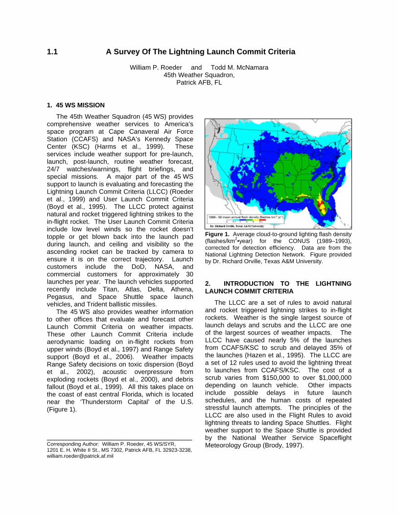
Most of the other LLCC infer the presence of dangerous electric fields aloft through the phenomena that generate those fields. However, if the electric fields could be detected directly, this ‘electric fields aloft’ LLCC could eliminate several of the other LLCC and significantly reduce the number of LLCC required and increase launch opportunity. Specifically, LLCCs 3-7 and second part of 8 need not be applied if, during the 15 minutes prior to launch time, the instantaneous electric field aloft, throughout the volume of air expected to be along the flight path, does not exceed Ec, where Ec is provided as a function of altitude (Figure 3). This LLCC is not currently in use due to lack of available electric field profile sensors. Figure 3. Instantaneous Critical Electric Field, Ec, vs. Altitude. Note: The thresholds on electric field measurements at the surface in the LLCC are lower than 5 kV/m to allow for the effect of the surface screening layer. (Krider et al., 1998) The exact profile of Ec with altitude requires verification before operational implementation.

5.10. Triboelectrification LLCC
Do not launch if a vehicle has not been treated for surface electrification and the flight path will go through any clouds above the -10 °C level up to the altitude at which the vehicle’s velocity exceeds 3,000 Ft/sec. A vehicle is considered treated for surface electrification if all surfaces of the vehicle susceptible to precipitation particle impact have been treated to assure that the surface resistivity is less than 109 ohms/square, and all conductors on surfaces (including dielectric surfaces that have been treated with conductive coatings) are bonded to the vehicle by a resistance that is less than 105 ohms; or it has been shown by test or analysis that electrostatic discharges on the surface of the vehicle caused by triboelectrification by precipitation particle impact will not be hazardous to the launch vehicle or the mission. All space launch vehicles at CCAFS/KSC are treated or analyzed so that this LLCC does not apply. Most, if not all space launch vehicles, at other ranges are also treated or analyzed and exempt from this LLCC.
5.11. ‘Good Sense Rule’ LLCC
Even when the LLCC are not violated, if any other hazardous conditions exist, the Launch Weather Team will report the threat to the Launch Decision Authority. The Launch Decision Authority may ‘HOLD’ at any time based on the instability of the weather.
5.12. Orographic Cumulus LLCC
The standoff distance to cumulus clouds with tops above -10°C may be reduced from 5 NM to 3 NM if those cumulus clouds are orographically forced, isolated, and downwind of the launch site, and there is one or more field mills between the cloud and the flight path and all those field mills have had values greater than -100 V/m and less than +500 V/m for 15 minutes. This LLCC was developed to avoid needless launch scrubs based on operational observations at the Kodiak Space Launch Complex.
5.13. LLCC Definitions
The LLCC have 19 operational definitions, which are meant to aid the evaluation of LLCC and account for the available weather sensors and their capabilities. Some of these definitions have a specialized meaning within the LLCC context, and/or are non-standard within meteorology (Huschke, 1995), (Schneider, 1996). The words
with specific definitions are listed in Table 4 and defined as follows.
TABLE 4. LLCC Words With Specific Definitions. Some definitions are LLCC specific and are non-standard within meteorology.
Anvil Flight Path
Associated Graupel
Bright Band Moderate Precipitation
Cloud Edge Nontransparent
Cloud Layer Orographic
Cloud Top Precipitation
Cumulonimbus Cloud Transparent
Debris Cloud Thunderstorm
Electric Field Measurement Aloft
Weather Disturbance
Electric Field Measurement At The Surface
Within
Field Mill Anvil: Stratiform or fibrous cloud produced by
the upper level outflow or blow-off from thunderstorms or convective clouds.
Associated: Used to denote that two or more clouds are causally related to the same weather disturbance or are physically connected. ‘Associated’ is not synonymous with occurring at the same time. An example of clouds that are not associated is air mass clouds formed by surface heating in the absence of organized lifting. Also, a cumulus cloud formed locally and a physically separated cirrus layer generated by a distant source are not associated, even if they occur over or near the launch site at the same time. ‘Weather Disturbance’ has a specific LLCC definition, which is provided elsewhere in this section.
Bright Band: An enhancement of radar reflectivity caused by frozen hydrometeors falling through the 0°C level and beginning to melt.
Cloud Base: The visible cloud base is preferred. If this is not possible, the 0 dBZ radar reflectivity cloud base is acceptable.
Cloud Edge: The visible cloud edge is preferred. If this is not possible, then the 0 dBZ radar reflectivity cloud edge is acceptable.
Cloud Layer: A vertically continuous array of clouds, not necessarily of the same type, whose bases are approximately at the same level.

Cloud Top: The visible cloud top is preferred. If this is not possible, then the 0 dBZ radar reflectivity cloud top is acceptable.
Cumulonimbus Cloud: Any convective cloud with any part above the -20°C temperature level.
Debris Cloud: Any cloud, except an anvil cloud, that has become detached from a parent cumulonimbus cloud or thunderstorm, or that results from the decay of a parent cumulonimbus cloud or thunderstorm. ‘Cumulonimbus Cloud’ has a specific LLCC definition, which is provided elsewhere in this section.
Electric Field Measurement Aloft: The magnitude of the instantaneous, vector, electric field (E) at a known position in the atmosphere, such as measured by a suitably instrumented, calibrated, and located airborne-field-mill aircraft.
Electric Field Measurement At The Surface: The one-minute arithmetic average of the vertical electric field (Ez) at the ground measured by a ground based field mill. The polarity of the electric field is the same as that of the potential gradient; that is, the polarity of the field at the ground is the same as the dominant charge overhead. Note: electric field contours (analyzed isopleths) shall not be used for the electric field measurement at the surface.
Field Mill: A specific class of electric field sensor that uses a moving ground conductor to induce a time-varying electric charge on one or more sensing element in proportion to the ambient electrostatic field.
Flight Path: The planned flight path including its uncertainties (“error bounds”).
Graupel: Heavily rimed snow particles, often called snow pellets; often indistinguishable from very small soft hail except for the size convention that hail must have a diameter greater than 5 mm. Sometimes distinguished by shape into conical, hexagonal, and lump (irregular) graupel.
Moderate Precipitation: A precipitation rate of 0.10 or greater, or a radar reflectivity factor of 30 dBZ or greater.
Nontransparent: Opposite of ‘Transparent’. Sky cover through which forms are blurred, indistinct, or obscured is nontransparent. Note: nontransparency must be assessed for launch time. Sky cover through which forms are seen distinctly only through breaks in the cloud cover is considered nontransparent. Clouds with a radar reflectivity of 0 dBZ or greater are also considered nontransparent. ‘Transparent’ has a specific
LLCC definition, which is provided elsewhere in this section.
Orographic: Associated with or induced by the presence of mountains
Precipitation: Detectable rain, snow, sleet, etc. at the ground, or virga, or a radar reflectivity greater than 18 dBZ.
Thunderstorm: Any convective cloud that produces lightning.
Transparent: Sky cover is transparent if higher clouds, blue sky, stars, etc. can be distinctly seen from below, or if terrain, buildings, lights on the ground, etc., can be distinctly seen from above. Note: visible transparency is required. Transparency must be assessed for launch time. Sky cover through which forms are seen distinctly only through breaks in the cloud cover is considered nontransparent. ‘Nontransparent’ has a specific LLCC definition, which is provided elsewhere in this section.
Weather Disturbance: A weather system where dynamical processes destabilize the air on a scale larger than the individual clouds or cells. Examples of disturbances are fronts, troughs and squall lines.
Within: Used as a function word to specify a margin in all directions (horizontal, vertical, and slant separation) between the cloud edge or top and the flight path. For example, “within 10 NM of a thunderstorm cloud” means that there must be a 10 NM margin between every part of a thunderstorm cloud and the flight path. ‘Cloud Edge’, ‘Cloud Top’, and ‘Flight Path’ have specific LLCC definitions, which are provided elsewhere in this section. 6. LLCC EVALUATION PROCESS
6.1. Launch Weather Team
The Launch Weather Team (LWT) must have clear and convincing evidence, and unanimous agreement, that the LLCC are not violated before evaluating the LLCC as ‘green’. If any LWT member has any doubt, then the LLCC are evaluated as violated, potentially delaying or scrubbing the launch. A ‘safety first’ attitude is mandatory. The 45 WS uses a Launch Weather Team (LWT) of up to eight people to forecast and evaluate LLCC during a launch. LWT members can include: Lead Launch Weather Officer (LWO), an optional Deputy LWO, Deputy LWO for Radar and Lightning Systems, Deputy LWO for

Weather Reconnaissance Aircraft, Launch Weather Director (normally the Launch Weather Operations Flight Commander), Launch Weather Commander (normally the 45 WS Commander or Operations Officer), and two Range Weather Forecasters. This many people may be required to evaluate the complex LLCC under rapidly changing threatening weather conditions and to analyze data from the numerous and diverse weather sensors used by 45 WS. A Lead LWO is assigned to each launch vehicle program to specialize in their weather requirements. LWOs must finish formal training and testing for certification, and recurring training and testing thereafter.
During a launch attempt, the Lead LWO coordinates the many weather inputs from the other LWT members, evaluates the LLCC, and serves as single weather voice to the launch community. A Deputy LWO may be assigned to assist the Lead LWO depending on length of launch window, complexity of the expected weather, briefing schedule, and amount of any special weather support requirements. The Deputy LWO is often assigned for the tanking and/or Tower Roll for long launch windows to reduce fatigue for the Lead LWO or to comply with restrictions for on-duty time. This Deputy LWO position may also be used for training, under the supervision of a certified LWO/trainer. The Deputy LWO for radar and lightning systems monitors these systems in coordination with the other LWOs, evaluates the LLCC, and reports LLCC evaluations and observations to the Lead LWO and other LWOs. The Deputy LWO for weather reconnaissance aircraft directs the aircraft to the desired height and location, and requests specific pilot reports in coordination with the other LWOs, evaluates the LLCC, and reports LLCC evaluations and observations to the Lead LWO and other LWOs.
The Launch Weather Director is a certified LWO and coordinates the activities of the LWT, provides assistance to individual LWOs as required to manage work flow, and provides oversight to the LLCC evaluation process. Before a violated “red” LLCC may be declared “green”, the Launch Weather Director must give final approval. The Launch Weather Commander is certified on all knowledge aspects of the LWO position LWO and provides command-level oversight to the entire LWT process as well as technical advice and explanations to the Eastern Range Space Launch Commander.
The Launch Weather Forecasters are the normal forecasters who are on-duty 24/7. They
provide meteorological input to the LWT and coordinate any local weather advisories, watches, warnings, and forecasts with the Lead LWO to ensure consistency between the launch weather and routine weather support.
Immediately after the launch, review meetings are held to identify opportunities for improvements. Launch reports are written to document events for future reference. In the unlikely event of a catastrophic loss of rocket, many additional actions are required by the LWT to support the accident investigation team: data saves, extra reports, requested special weather support, etc. (Winters et al., 2004).
In addition to the LWT itself, the Range Technical Services contractor, currently Computer Sciences Raytheon, provides a wide range of meteorological observations, including quality control of upper air winds, and systems maintenance during the countdown.
The Applied Meteorology Unit (AMU) (Bauman et al., 2004) also provides staff during a launch in case a question requiring their special expertise arises and for continued operations familiarization. The need for special consultation is rare--only three consultations have been needed in 15 years.
6.2. Weather Systems
The 45 WS uses many weather systems to forecast and evaluate the LLCC (Table 5). A full description of the lightning sensors is provided by Harms, et al., 1997), and are summarized in Table 6.
The strengths and weaknesses of the various lightning sensors synergistically combine to produce a good analysis of the local lightning. Some of the more unique systems are described as follows. The Lightning Detection And Ranging (LDAR) is a 7-antenna VHF time-of-arrival system, providing a four-dimensional depiction of the lightning, including in-cloud, cloud-to-cloud, cloud-to-air, and cloud-to-ground lightning (Figure 4). The Cloud to Ground Lightning Surveillance System (CGLSS) is a short-baseline 6-sensor direction-finding and time-of-arrival (IMPACT) system (Figure 5). CGLSS uses the IMProved Accuracy via Combined Technology (IMPACT) sensors (Cummins et al., 1998) like those in the National Lightning Detection Network (NLDN). The Launch Pad Lightning Warning System (LPLWS) is a network of 31 surface electric field mills (Figure 6). Other systems include: two weather radars (Figure 7), reconnaissance aircraft, satellite imagery, local radiosonde at CCAFS (Figure 7), local surface observations, and NLDN. The two weather radars are a modified 5-

cm WSR-74C at Patrick AFB with an Integrated Radar Information System post-processor, and a 10-cm WSR-88D at Melbourne. The 45 WS also has access to many other weather sensors; a full
description is given by Harms, et al. (1998). The integration of all this intricate weather data required to evaluate the many complex LLCC can be extremely demanding.
TABLE 5. Systems Used In LLCC Evaluation At CCAFS/KSC
LLCC*
SYSTEM 1 2 3 4 5 6 7 8 9n 10t 11 12
LDAR P P B
P --- P N/A
CGLSS P B P --- P N/A
LPLWS R B
R R R B
P --- P N/A
NLDN B B --- P N/A
Radars R P R
P R
P R
P P P --- P P N/A
Aircraft R P R
P P P P R
P R --- P P N/A
MetSat B B P P P R --- P P N/A
RAOB P P P P R
R --- P P N/A
P: Primary sensor(s) for that LLCC n: ‘E-Filed Aloft’ LLCC not used; no sensor available B: Back-Up/Ancillary sensor(s) for that LLCC *: LLCC number corresponds to order in Table 1 R: Safely Relax LLCC limits, under some conditions t: ‘Triboelectrification’ LLCC N/A to most vehicles N/A: orographic cumulus does not occur at CCAFS/
KSC, so this LLCC is not evaluated there
TABLE 6. Technical Characteristics Of Lightning Systems At CCAFS/KSC LDAR CGLSS LPLWS NLDN
Sensor type VHF time-of-arrival
MDF Field mill Hybrid (MDF/TOA)
Number of sensors 7 5 31 105
Sensor spacing 6 - 10 km 20 km 2 - 5 km 200 - 400 km
Effective range 100 km 100 km ≈ 20 km National
Lightning detected All Cloud-to-ground All Cloud-to-ground
Flash detection efficiency
≈ 100% 98% > 90% 95%
Lightning process located
VHF radiation Return stroke, ground strike point
Center of charge Return stroke, ground strike point
Locating accuracy 100 m 0.25 km 2 – 20 km ≈ 0.5 km
Locations per flash 10 - 1000 1-5 1 ≈1
Peak location rate 10,000 s-1 74 min-1 85 min-1 800 min-1
Display Stand-alone Stand-alone and MIDDS
Stand-alone and MIDDS
Stand-alone
Source Locally developed (NASA)
Commercial product Locally developed (AF/NASA)
Commercial service
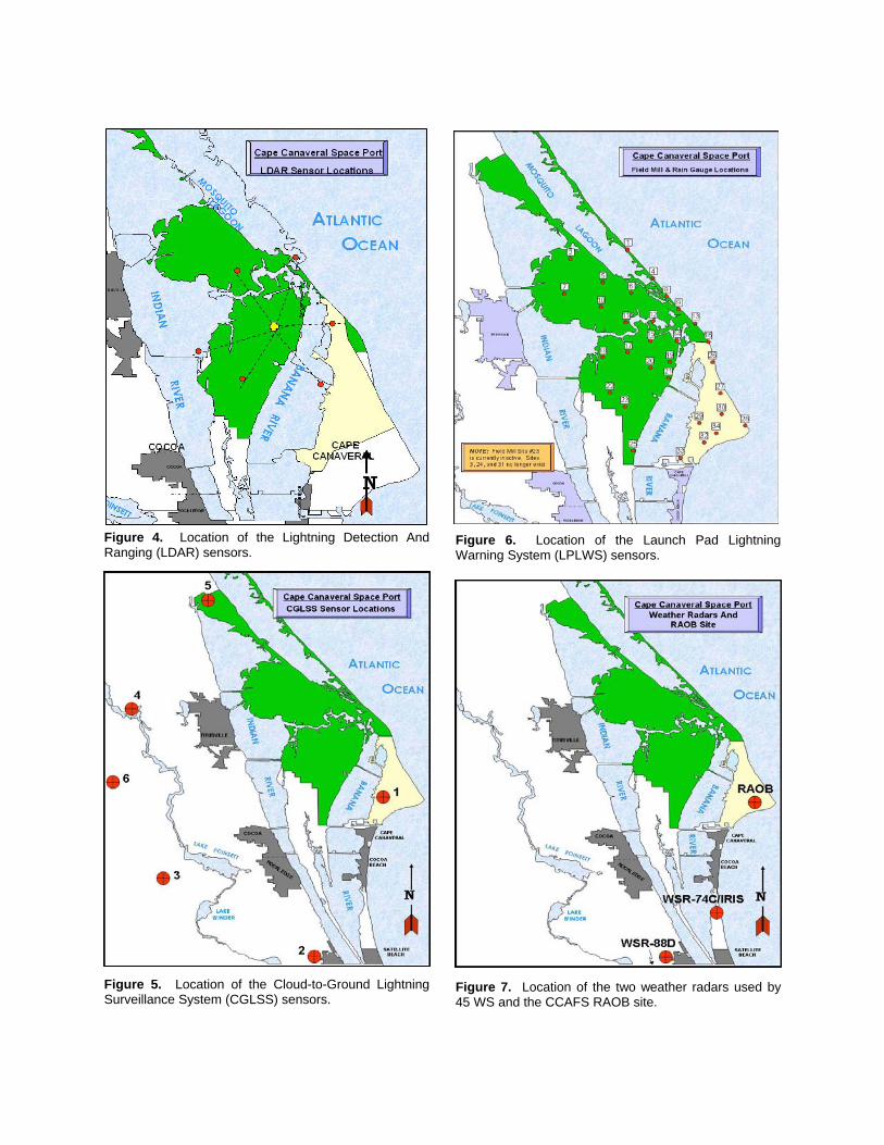
Figure 4. Location of the Lightning Detection And Ranging (LDAR) sensors. Figure 5. Location of the Cloud-to-Ground Lightning Surveillance System (CGLSS) sensors.
Figure 6. Location of the Launch Pad Lightning Warning System (LPLWS) sensors. Figure 7. Location of the two weather radars used by 45 WS and the CCAFS RAOB site.

6.3. LLCC Training
The training and certification of a Launch Weather Officer (LWO) is a very rigorous process controlled by the Air Force Space Command instructions governing ‘Mission Support’ positions. Initial training is done under a formally approved ‘Initial Plan of Instruction’ that includes lectures, reading, and hands-on operations. The training is done by a trainer who is certified both as a LWO and as a trainer. LWO certification includes both a written test and task evaluation. Certification is done by an independent evaluator (who didn’t do the training), and who is certified both as a LWO and as an evaluator. Final approval for a LWO requires the approval of both the 45 WS Commander. Initial LWO certification requires 21 days of fulltime training. The LWO position requires annual recertification. Recurring training is conducted monthly under a formally approved ‘Annual Plan Of Instruction’ and includes both seminar and tests. Much of the LLCC training is graphics based (Figure 8). The entire process of LWO training and certification is formally inspected annually by the 45 OG. Figure 8. Example of graphics based training. This is just one part of one LLCC. 7. LLCC CHANGE PROCESS
Atmospheric electricity is one of the least mature meteorological sciences. New data and operational experience are continually leading the range weather community to consider improvements in the LLCC. Therefore, LLCC evolution is an inherently iterative process. The LLCC change process is summarized in Figure 9. The LLCC change process begins with a proposal to the Lightning Advisory Panel (LAP)–proposals may come from the LAP itself. The LAP is a group of atmospheric electricity experts from universities,
national laboratories, and industry. The LAP is intentionally independent of launch operations, to ensure objectivity. The LAP advises the USAF and NASA primarily on the LLCC, but also on lightning forecasting, and other atmospheric electricity issues. The current LAP membership is listed in Table 7. Proposed LLCC changes are discussed extensively, in coordination with the operational range weather community.
1
-20°C-20°C
Thick Cloud RuleThick Cloud Rule
0 °C0 °C4500 ft
4500 ft
4500 ft
OK
OK
Rule 6Rule 6
4500 ftOK
OK
DON’T launch if the flight path will carry the vehicle through nontransparent parts of a cloud layer that is:
DON’T launch if the flight path will carry the vehicle through nontransparent parts of a cloud layer that is:
(1) Greater than 4500 ft thick and any part of cloud layer along the flight path is located between the 0 deg C and -20 deg C levels; OR . . . Unless . . .
(1) Greater than 4500 ft thick and any part of cloud layer along the flight path is located between the 0 deg C and -20 deg C levels; OR . . . Unless . . .
Figure 9 LLCC Change Process
TABLE 7. Lightning Advisory Panel Members
MEMBER AFFILIATION
Dr. Christian Marshall Space Flight Center
Dr. Dye National Center for Atmospheric Research (emeritus)
Dr. Koons (deceased 2005)
Aerospace Corporation
Dr. Krider (chairman)
University of Arizona
Dr. Rust National Severe Storms Laboratory
Dr. Walterscheid Aerospace Corporation
Dr. Willet Private Consultant (formerly Air Force Research Laboratory)
After the LAP recommends a LLCC change, the operational range weather community decides whether to accept the change, and begins the staffing process for formal approval. The operational weather community includes the 45 WS, 30 WS, KSC Weather Office, and the NWS Spaceflight Meteorology Group. Concurrence and coordination is required from a large number of organizations: USAF/NASA Range Safety Panel, 45th and 30th Operations Groups, commercial launch providers, Space and Missile Systems Center, Naval Ordnance Test Unit, and Aerospace Corporation. This large number of concurrences and coordination is required to ensure the LLCC are standardized across all launch vehicles. However, this can lead to a long duration process–even a “simple one word change” requires iteration back to the LAP.
Final approval is granted by 45th Space Wing, NASA, 30th Space Wing, and Air Force Space Command. The LLCC change is implemented operationally, after training and testing of the LWOs. 8. FUTURE CHANGES TO THE LIGHTNING LAUNCH COMMIT CRITERIA
8.1. On-going LLCC Improvement Efforts
The results from the Airborne Field Mill Experiment continue to be analyzed for further LLCC improvements. For example, one study has indicated that the electric fields fall off with distance from anvil clouds faster than had been believed previously (Ward and Merceret, 2004). Further analysis could lead to a new anvil LLCC with considerably reduced standoff distances. The reduction could be as much as a factor of two to three.
The Airborne Field Mill Experiment was initially designed to improve both the anvil LLCC and the stratiform ‘thick cloud’ LLCC. Unfortunately, no data were collected on these thick clouds, due to a minor drought during the experiment, even though the data collection period was scheduled for the climatological peak of this phenomenon at the Eastern Range. However, this LLCC is considered the most conservative of the LLCC, with a false alarm rate of up to 90%. It is also a frequent source of launch delays and scrubs, especially at the Western Range at Vandenberg AFB on the central California coast. Therefore, the science team would like to try to improve the ‘Thick Cloud’ LLCC, but those improvements are unlikely unless another data collection can be funded.
The Federal Aviation Administration has funded an effort to document the justification for each of the LLCC to improve training and build acceptance for the LLCC at future commercial spaceports that will fall under FAA oversight. At this time, these commercial spaceports are intended for smaller suborbital rockets, primarily for tourism. These LLCC rationales will be also useful for the rest of the space launch community. Indeed, these rationales had been desired and planned, but work was never done due to higher priority LLCC work and lack of funding.
The Federal Aviation Administration has also funded an on-going study to determine if smaller suborbital rockets could be safely launched using LLCC with relaxed thresholds or even eliminate some of the LLCC. After all, smaller rockets have exhaust plumes with smaller ‘conductive lengths’ and should be less likely to cause triggered lightning than the larger rockets used for orbital launches. Recent research with small rocket triggered lightning experiments has better refined our understanding of what electric field near the surface is needed to cause triggered lightning. Now we need to understand better how different rockets amplify preexisting electric fields differently.
NASA has funded an on-going study to better understand the role of pressure on conditions for triggered lightning. This study is being conducted jointly by researchers at three organizations in Moscow, Russia: 1) Krzhizhanovesky Power Engineering Institute, 2) Institute of Physics and Technology, and 3) Institute for Problems in Mechanics. The study should conclude by end of 2005. Recommendations for follow-on research may extend delivery of final results to a later date.
The 45 WS is preparing a list of recommendations about the LLCC based on recent operational experience. This list will be briefed to the LAP for consideration in future LLCC changes, probably in early 2006.
8.2. Future LLCC Improvements
The 45 WS has submitted a proposal for Range Commanders’ Council funding for a LLCC climatology and sensitivity analysis. The climatology would aid mission planning by providing a more objective estimate of probability of violating the LLCC versus time of year and time of day. The climatology would also aid the Launch Weather Officers in their daily pre-launch forecasts that usually begin 3 days before launch and include a prediction of the probability that the launch will be scrubbed due to any of the Lightning and User Launch Commit Criteria. The sensitivity

analysis would identify if any small changes in the thresholds of the LLCC will result in relatively large gains of launch opportunity. These opportunities would then be suggested to the Lightning Advisory Panel to see if the changes can be implemented while maintaining launch safety, especially if the improvement is in a LLCC that is climatologically more frequent.
The 45 WS has begun acquisition of a new weather radar to replace the aging WSR-74C/IRIS at Patrick AFB. The new radar will have dual polarization capability. Dual polarization capability should definitely help the 45 WS mission through improved lightning advisories and convective wind warnings. It may also be able to detect some electric fields in clouds under some conditions and so may help in LLCC evaluation.
The remainder of these suggestions are for desired future LLCC improvements, but funding has not been identified and none of these projects have projected start dates. One desired LLCC improvement for the future is the development of LLCC prediction tools using numerical weather prediction models. Studies are required on how to convert model outputs into LLCC evaluation conditions. For example, model cloud thickness versus temperature levels might correlate well to some LLCC conditions. The performance of such tools would have to be known before they could be used operationally. The use of numerical models to predict LLCC conditions should help improve the pre-launch forecasts, which contain a large element of subjectivity by the Launch Weather Officers.
Little research on atmospheric electricity has been done in cold moist environments such as at Kodiak Space Launch Complex in Alaska. The surface electric field mill there has indicated that cumulus clouds there are often highly electrified. This may not be surprising given their cold temperatures and steep lapse rates, making the 0 °C to -20 °C electrification layer readily available to even shallow convection. However, for reasons that are not well understood, these clouds rarely produce natural lightning. Another phenomenon noted at Kodiak is that blowing snow often produces strong surface electrification. Under some conditions, this electrification may be contained to only a shallow layer and not be a triggered lightning threat. However, electric field profile studies would need to be done before incorporating this into the LLCC. In addition, a general survey of the atmospheric electricity and associated phenomena at Kodiak Space Launch Complex would be useful.
In the very long-term, the LLCC could be significantly improved if a remote sensing device to profile electric fields under all atmospheric conditions were available. If an operationally-viable, cost-effective method existed, then the ‘Electric Fields Aloft’ LLCC could be used to avoid using over five of the current LLCC. Many of the LLCC are meant to infer the presence of electric fields strong enough for rocket triggered lightning. A device that measures the electric field directly, from clear air to stratus to thunderstorms, would eliminate the need for those inferential LLCC. An airborne field mill aircraft has been considered, but local analysis showed it would not be cost-effective, especially considering that the electric fields change so quickly, easily in a matter of minutes, that the first part of the electric field profile from the aircraft would no longer be representative by the time aircraft finished the profile. Also, the aircraft would have to complete many profiles over an area of several square miles, causing even more problems with out of date data. In addition, the aircraft has to leave the protected airspace for launch to occur, introducing several more minutes of age to the data. A fleet of airborne field mill aircraft would be required, making the cost of operations too high. Finally, maintaining and calibrating airborne electric fields is very difficult and probably exceeds what could be accomplished in real-world operations and would add to the cost of the program. This also introduces a danger to flight safety since a miscalibrated field mill could lead to launch under unsafe conditions. Obviously a scanning remote sensor for electric field profiles is required for both in-cloud and out-of-cloud conditions. However, the 45 WS and KSC have solicited proposals for such a sensor, but no viable solutions have been forth coming. Unfortunately, such a sensor will likely require new basic research.
An operational sensor/technique for objective measurement of transparency is desired. The new 1998 LLCC made much more use of transparency to safely relax the LLCC. The LLCC definition of transparency was also improved. However, in large part, the operational evaluation of transparency still remains subjective.
9. SUMMARY
The threat of natural and triggered lightning has significant impact on space launch. Approximately 35% of launches from CCAFS/KSC are delayed, and 5% scrubbed, due to the Lightning Launch Commit Criteria. These LLCC are a set of twelve rules providing protection

against the lightning threat. These rules are complex and very atypical of operational meteorology, as are some of the weather sensors used in their evaluation. The importance of triggered lightning, and the distinction from natural lightning, can not be overemphasized. The LLCC undergo continuous incremental improvement and several projects are on-going for further improvements. In addition, other projects have been proposed or are desired to continue the LLCC improvement process into the future. The 45 WS is always open to suggestions and proposals for improved LLCC.
ACKNOWLEDGMENTS: The authors express their deepest gratitude to the LAP for their dedication to scientific accuracy in the LLCC, and to Mr. Madura, manager of the NASA Weather Office, for tirelessly striving for LLCC improvement. Without their selflessness, the LLCC would not have achieved their current level of excellence. This paper was reviewed by Col Bedard, Maj Cocks, Mr. Boyd of 45 WS and Mr. Madura of KSC. Sections of this paper were reviewed by Maj McAleenan of 45 WS and Dr. Merceret of KSC. The suggestions for future research at Kodiak Space Launch Complex came from Dr. Krider of the University of Arizona and LAP Chairman. REFERENCES Aerospace, 1988: Launch Vehicle
Lightning/Atmospheric Electrical Constraints Post-Atlas/Centaur 67 Incident, Aerospace Corporation Report #TOR-0088(3441-45)-2, 31 Aug 88, 12 pp
Bauman III, W. H., William P. Roeder, R. A. Lafosse, D. W. Sharp, and F. J. Merceret, 2004: The Applied Meteorology Unit--Operational Contributions Tp Spaceport Canaveral, 11th Conference on Aviation, Range, and Aerospace Meteorology, 4-8 Oct 04, Paper 6.3
Boyd B. F., M. E. Fitzpatrick, C. R. Parks, P. N. Rosati and R. W. Lamoreaux, 2006: Ensuring Environmental Safety For Space Launch. , 12th Conference on Aviation, Range, and Aerospace Meteorology, 29 Jan-2 Feb 06, Paper 8.6
Boyd, B. F., D. E. Harms, K. A. Winters, P. N. Rosati, C. R. Parks, and K. B. Overbeck, 2002: Boundary Layer Influences On Forecasting Toxic Corridors At The Eastern Range In Support Of Space Launch, 10th Conference on Aviation, Range, and Aerospace Meteorology, 13-16 May 2002, 182 – 185
Boyd, B. F., D. E. Harms, P. N. Rosati, C. R. Parks, and K. B. Overbeck, 2000: Weather Support To Range Safety For Forecasting Atmospheric Sonic Propagation, 9th Conference on Aviation, Range, and Aerospace Meteorology, 11-15 Sep 00, 432-437
Boyd, B. F., D. E. Harms, M. E. Fitzpatrick, R. P. Stout, P. N. Rosati, D. D. Berlinrut, C. R. Parks, and K. B. Overbeck, 1999: Weather Support To Range
Safety, JANNAF, S&EPS, 26-30 Apr 99, CPIA Pub 687, Vol. I, 59-69
Boyd, B. F., S. Heckman, and T. Adang, 1997: Upper Air Data Used In Weather Support To The Eastern Range And Kennedy Space Center, 7th Conference On Aviation, Range, And Meteorology, 2-7 Feb 97, 20-25
Boyd B. F., W. P. Roeder, J. B. Lorens, D. S. Hazen, and J. W. Weems, 1995: Weather Support To Pre-Launch Operations At The Eastern Range And Kennedy Space Center, 6th Conference On Aviation Weather Systems, 15-20 Jan 95, 135-140
Brody, F.C., R.A. Lafosse, D.G. Bellue, and T.D. Oram, 1997: Operation Of The National Weather Service Spaceflight Meteorology Group, Weather and Forecasting, 12, 526-544
Busse, J. R, Chairman Investigation Board 1987: Report Of Atlas/Centaur-67/FLTSATCOM F-6 Investigation Board, Volume I–Final Report, 15 Jul 87, 326 pp
Cummins, K. L., M. J. Murphy, E. A. Bardo, W. L. Hiscox, R. B. Pyle, and A. E. Pifer, 1998: A Combined TOA/MDF Technology Upgrade Of The U.S. National Lightning Detection Network, Journal of Geophysical Research, 103, 9035-9044
Desordi, S. P., 1999: Weather Impacts To Launch Operations At Vandenberg AFB CA, 8th Conference On Aviation, Range, And Aerospace Meteorology, 10-15 Jan 99, 573-577
Dye, J. E., S. Lewis, M. G. Bateman, D. M. Mach, F. J. Merceret, J. G. Ward, C. A. Grainger, 2003: Final Report On The Airborne Field Mill Project (ABFM) 2000-2001 Field Campaign, NASA/TM-2004-211534, 127 pp.
Harms, D. E., A. A. Guiffrida, B. F. Boyd, L. H. Gross, G. D. Strohm, R. M. Lucci, J. W. Weems, E. D. Priselac, K. Lammers, H. C. Herring and F. J. Merceret, 1999: The Many Lives Of A Meteorologist In Support Of Space Launch, 8th Conference On Aviation, Range, And Aerospace Meteorology, 10-15 Jan 99, 5-9
Harms, D. E., B. F. Boyd, R. M. Lucci, and M. W. Maier, 1998: Weather Systems Supporting Launch Operations at the Eastern Range, AIAA 36th Aerospace Sciences Meeting and Exhibit, 12-15 Jan 98, Paper 98-0744
Harms, D. E., B. F. Boyd, R. M. Lucci, M. S. Hinson, and M. W. Maier, 1997: Systems Used To Evaluate The Natural And Triggered Lightning Threat To The Eastern Range And Kennedy Space Center, 28th Conference on Radar Meteorology, 240-241
Heritage, 1988: Heritage Committee Report, Aerospace Corporation Report #TOR-0088(3441-45)-2, date, pages
Huschke, R. E., 1995: Glossary Of Meteorology, American Meteorology Society, Boston, MA, 638 pp.
Krider, E. P., H. C. Koons, R. L. Walterscheid, W. D. Rust, and J. C Willet, 1999: Natural And Triggered
Lightning Launch Commit Criteria (LCC), Aerospace Report No. TR-99(1413)-1, The Aerospace Corporation, 15 Jan 99, 22 pp.
Krider, E. P., R. C. Noggle, M. A. Uman, and R. E. Orville, 1974: Lightning And The Apollo 17/Saturn V Exhaust Plume, Journal Of Spacecraft And Rockets, Vol. 11, No. 2, Feb 74, 72-75
Hazen, D. S., W. P. Roeder, B. F. Boyd, J. B. Lorens, and T. L. Wilde, 1995: Weather Impact On Launch Operations At The Eastern Range And Kennedy Space Center, 6th Conference On Aviation Weather Systems, 15-20 Jan 95, 270-275
Maier, M. W., 1999: Weather Impacts On Space Launch Operations At The United States Eastern Range, 8th Conference On Aviation, Range, And Aerospace Meteorology, 10-15 Jan 99
Marshall, T. C., W. D. Rust, M. Stolzenberg, W. P. Roeder, and P. R. Krehbiel, 1999: A Study of Enhanced Fair-Weather Electric Fields Occurring Soon After Sunrise, Journal Of Geophysical Research, Vol. 104, No. D20, 27 Oct 99, 24,455-24,469
McNamara, T. M., W. P. Roeder, J. W. Weems, S. B. Cocks, and B. F. Boyd, 2005: Unique Uses of Weather Radar for Space Launch, 32nd Conference on Radar Meteorology, Albuquerque, NM, 23-29 Oct 2005, 13 pp.
Merceret, F. J., D. Short, J. G. Ward, 2006a: Radar Evaluation Of Optical Cloud Constraints To Space Launch Operations, Journal Of Spacecraft And Rockets, accepted for publication 16 Sep 05, publication expected during 2006, 5 pp.
Merceret, F. J., M. McAleenan, T. M. McNamara, J. W. Weems, and W. P. Roeder, 2006b: Implementing The VAHIRR Launch Commit Criteria Using Existing Radar Products, 12th Conference on Aviation, Range, and Aerospace Meteorology, 29 January-2 February 2006, 7 pp.
Merceret, F.J. and H. Christian, 2000: KSC ABFM 2000 - A Field Program to Facilitate Safe Relaxation of the Lightning Launch Commit Criteria for the American Space Program, 9th Conference on Aviation and Range Meteorology, 11-15 September 2000, Paper # 6.4
Nanevicz, J. E., J. S. Thayer, and H. Heritage, 1988: An Aircraft-Borne Electric Field Measuring System For Rocket Launch Support, International Aerospace And Ground Conference On Lightning And Static Electricity, Oklahoma City, OK, 87-93
Poniatowski, K. S., 1987: Manned/Unmanned Launch Vehicle Weather History At Lift-Off 1960 To Present, Unpublished, NASA Hqs, May 1987, 55 pp.
Roeder, W. P., D. L. Hajek, F. C. Flinn, G. A. Maul, and M. E. Fitzpatrick, 2003: 5th AMS Conference on Coastal Atmospheric and Oceanic Prediction and Processes, Seattle, WA, 6-8 August 2003, 5 pp.
Roeder, W. P., J. E. Sardonia, S. C. Jacobs, M. S. Hinson, A. A. Guiffrida, J. T. Madura, 1999:
Avoiding Triggered Lightning Threat To Space Launch From The Eastern Range/Kennedy Space Center, 8th Conference on Aviation, Range and Aerospace Meteorology, 10-15 Jan 99, 120-124
Roeder, W. P., 1995: Operational Impacts And Identification of Chaff On Weather Radar, 27th Conference On Radar Meteorology, 9-13 October 1995, 373-375
Sardonia, J. E., and J. T. Madura, 2002: Kodiak Star: An Overview Of Operational Weather Support At The Kodiak Launch Complex For Alaska’s First Orbital Space Launch, 10th Conference on Aviation, Range, and Aerospace Meteorology, 13-16 May, 172-174
Schneider, S. H., Editor In Chief, 1996: Encyclopedia Of Climate And Weather, Oxford University Press, 929 pp.
Ward, J. G., and F. J. Merceret, 2004: Electric Field Magnitude And Radar Reflectivity As A Function Of Distance From Cloud Edge, NASA Technical Memo TM-2004-211530, Sep 2004, 25 pp.
Winters, K. A., W. P. Roeder, J. T. Madura, and H. C. Herring 2004: Use of Archived Weather Data From Spaceport Florida In Support Of Space Shuttle Columbia Accident Investigation, 14th Conference on Applied Climatology, 11–15 January 2004, Paper P4.7, 7pp.