an00263 - generic drive interface - using siemens s7 plcs ......microsoft word - an00263 - generic...
TRANSCRIPT

ABB Motion control products 1 new.abb.com/motion
Ready to use PLC function blocks, combine with a pre-written Mint application for simple control of MicroFlex e190 and MotiFlex e180 drives via PROFINET IO
Introduction
This application note details how to import and configure the ABB Generic Drive Interface (GDI) and associated TIA portal library ‘ABB Motion GDI Library’ using TIA portal (version 15 or later) project and any SIMATIC S7 CPU (S7-1200, S7-1500, S7-400) using FW 3.3.12 or later. The same principles can be applied for older Simatic Step 7 projects though firmware versions before V3.xx should be avoided. The library provides pre-written data structures and function blocks that integrate seamlessly with the Mint based GDI and allow suitable Siemens PLCs to control ABB drives running Mint programs that support PROFINET IO (MicroFlex e190 and MotiFlex e180). Note that MicroFlex e190 and MotiFlex e180 drives must be provided with the Mint memory card (option code +N8020). The instructions promote consistency in all projects and greatly simplify the development of Siemens PLC motion control applications where simple point to point motion is required. This document assumes that the reader has basic knowledge of Siemens PLCs, SIMATIC S7, PROFINET IO configuration, Mint Workbench and the Mint GDI. It is recommended that the reader refers to application note AN00204 for details on the Mint GDI operation and configuration. Pre-requisites
We will need to have the following to work through this application note:
Mint Workbench build 5852 or later (see www.abb.com/motion or new.abb.com/drives/low-voltage-ac/motion for latest
downloads and support information)
An ABB Motion drive (such as MotiFlex e180 or MicroFlex e190 drive) with build 5900 or later firmware (only the drive
is required, a motor is not needed just to test data exchange with a PLC)
The latest version of the Mint GDI program (Version 2.30 or later)
A PC or laptop running TIA portal version 15 (or later)
A SIMATIC S7 CPU (S7-1500, S7-1200, S7-300, S7-400) using FW 3.3.12 or later
4 port (or more) Ethernet switch
Ethernet cables to connect the PROFINET coupler, PLC processor, ABB Motion Drive and PC to the Ethernet switch
It is assumed the reader has a basic working knowledge of Siemens TIA Portal, ABB Motion drives and Mint Workbench. Throughout the remainder of this document any references to Microflex e190 may be replaced by Motiflex e180 if we intend to use this drive instead.
Motion Control Products
Application note Generic drive interface: Using Siemens S7TM PLC range via Profinet
AN00263
Rev C

Application note Generic drive interface: Using Siemens S7 PLC range via Profinet AN00263
ABB Motion control products 2 new.abb.com/motion
Configuring the device (station) name
The PROFINET station name is identical to the device name assigned by the user. The name can be set via the following
methods:
Using the Identification page of the configuration wizard in Workbench (this is the simplest and therefore the recommended
method). The page contains detailed encoding information and the entered data is verified against the station name rules. The
configuration wizard does NOT support Punycode encoding:
Using the drive's PROFINET web page (accessible via the Mint Sidebar tray application). The web page allows the user to enter
a name that includes a Unicode character (e.g. ü) and this will be encoded using Punycode, however it is recommended to
avoid Unicode characters as it is only this web page that will display the name correctly – all other screens will show the “plain”
name…
Once the drive web page is open we can set the name for the drive by editing then pressing the Set button;
The station name is stored in the drive’s object dictionary (i.e. non-volatile storage). The drive performs an internal reboot after
setting the new value
Note: The station name can also be assigned by TIA Portal but that is not covered in this application note.
192.168.0.2
255.255.255.0
192.168.0.241
e1901
e190

Application note Generic drive interface: Using Siemens S7 PLC range via Profinet AN00263
ABB Motion control products 3 www.abb.com/motion
Configuring the drive’s IP address
The assignment of the drive’s IP address during boot-up (via Dynamic Host Configuration Protocol – DHCP) may be possible if this is supported by the master but a change in IP address might cause conflicts with a configuration made via Workbench so the use of DHCP is not recommended. Most PROFINET masters allow the user to keep the IP configuration as already present on the device. This is the preferred method for configuration, especially because the front port of the drive can be used for many networks simultaneously (e.g. PROFINET, Modbus TCP, ICM/Workbench connection). In the example we will change the Drive IP address to avoid a conflict with the PLC IP address. To set the drive’s IP address either…
Use the Configuration wizard in Workbench, select the Network tab and enter the required IP address for the host port (E3), network mask (usually 255.255.255.0) and gateway address (only used if there is a router between the PLC and the drive…..usually this is not the case so the gateway address should be set to an unused IP address on the same subnet)…
Or use the drive’s PROFINET web page (accessible via the link on the Mint Sidebar application dialog as before) Enabling the PROFINET service
PROFINET can be disabled for cyber security reasons. It is important to check the setting before trying to get online via PROFINET to the drive. All network services can be configured via the Services page within the configuration wizard in Workbench… LLDP and PROFINET both need to be selected for correct PROFINET operation. The PROFINET implementation does not provide a SYNC tick that is required for closed loop axis control via PROFINET. Instead the implementation exposes the drive’s internal NETDATA channels (0-999) allowing the PLC to read/write 32 bit integer or floating point values. This allows control of the axis via the Mint based Generic Drive Interface for example (as per the example included with the application note) or the user can create their own Mint applications and use PROFINET to exchange command/status/parameter data. It is possible to use the drive on an EtherCAT or Ethernet Powerlink (EPL) network (using the two real time Ethernet ports on the top of the drive) and simultaneously have a connection to a PROFINET master.

Application note Generic drive interface: Using Siemens S7 PLC range via Profinet AN00263
ABB Motion control products 4 new.abb.com/motion
Configuring the Generic Drive Interface (GDI) Mint program
The pre-written GDI Mint program only requires only a small amount of customisation to suit the user’s application (e.g. axis scale factor, definition of home input and homing method)”. Please refer to application note AN00204 for details.
Obtaining the GSDML file
The PROFINET master will require a GSDML file to be imported into its “device library”. The GSDML file can be retrieved via two different methods:
Download the file from the firmware page on the “ABB motion” internet page (go to Support by Product and select MotiFlex e180 or MicroFlex e190).
Download the file from the index page of the drive's home (web) page. The page hosts all fieldbus description files that are generated from the drive firmware during boot-up:
The file name is a compromise between GSDML specification and firmware release process. All files released with a specific firmware version must contain the release number in the file name. How this file is then used/imported depends on the specific vendor of the PROFINET master (PLC). Note: ABB Motion drives provide two different GSDML version files (v2.32 and v2.3). This is to allow operation with different versions of Siemens' TIA Portal.

Application note Generic drive interface: Using Siemens S7 PLC range via Profinet AN00263
ABB Motion control products 5 www.abb.com/motion
The following table shows the compatibility. There is also a v2.34 GSDML file available, but this is used for conformance testing only at present
This concludes the steps necessary for configuration of the drive, from this point onwards all topics relate to configuration of the PROFINET master (e.g. PLC).
Configuration and importing the drive’s GDS file into TIA Portal project
We should begin by opening our version of TIA portal and creating a new project. Next we should go to the ‘Configure a device’
view. Once this is open we can select ‘Add a new device’ and select the CPU type that matches the one that we will be using in
our project (in the below example this is a CPU 1515-2 PN). This will be the base object in the configuration.
To use any ABB Motion drive in our project we must first import the GSDML file into our project. To import the files into the
device repository of TIA portal, (where all General Station Description (GSD) files are stored) we must go to the toolbar, select
the ‘Options’ menu and select ‘Manage general station description files’ (GSD)

Application note Generic drive interface: Using Siemens S7 PLC range via Profinet AN00263
ABB Motion control products 6 new.abb.com/motion
Next, navigate to the location on the PC where have saved the GSDML file, select it and select ‘Install’.
When the installation is complete the drive’s GSD file should appear in the ‘Hardware Catalog’.
Note: The name of the file will be in the form ‘Gsdml-v[version]-abb-[drive type] [FW Version] [Date created].xml
Next ensure the ‘Topology view’ or ‘Network view’ is selected via the tab at the top, this will give a graphical network view in the
central pane. Using this view you can select the port in which the PROFINET cable will be connected. In this case we will select
Port_1. Once the port is selected you can configure the address in the properties window which will appear at the bottom of the
screen. In this case we will leave the PLC address set as default ‘192.168.0.1’.
‘Port_1’
Ensure the Hardware Catalog view is visible in the right hand pane. Select ‘catalog’ from the right hand pane drop down box if
it’s not already selected. Then navigate to Other Field Devices > PROFINET IO > Drives > ABB > Motion and then select the
correct drive (in the example below this is a MicroFlex e190). Once the correct drive has been selected we must double click on
it to add it to the device configuration.
Note: Ensure the drives IP address has been changed before proceeding to avoid a IP conflict.
Next, we must select the ‘Network view’ in the main window, then from the ‘Hardware catalog’ view (selected from the right of
the window) you must import the device from the relevant file in the hardware catalog. For ABB Motion control drives you must
go to ‘Other field devices > PROFINET IO > Drives > ABB > Motion > MicroFlex e190’. The drive will then appear in the main
window as an ‘unassigned device’.

Application note Generic drive interface: Using Siemens S7 PLC range via Profinet AN00263
ABB Motion control products 7 www.abb.com/motion
Double click on the newly added MicroFlex e190 node and TIA portal will automatically switch to the device view for the drive.
The device view allows us to configure the device name and IP address. To do this select the ‘General’ menu then ‘PROFINET
Interface [X1]’. To enter settings here press the ‘Add new subnet’ button. The settings we entered here should match the IP
address and device name that were entered in Mint Workbench earlier. We should also ensure the correct subnet is selected (in
case of multiple networks) and the correct device number is selected (in case of multiple drives)
.
Now the device has been configured we should return to the ‘Network View’. The e190 will now appear as a node with ‘no
assigned IO controller’. We must select the ‘Not assigned’ area on the e190 node symbol. This will then give us the option to
‘Assign to new IO controller’.
We must then select the correct IO controller which will be the PLC’s PROFINET interface
We will then see the e190 is assigned to be controlled by the PLC (below named PLC_1)

Application note Generic drive interface: Using Siemens S7 PLC range via Profinet AN00263
ABB Motion control products 8 new.abb.com/motion
Configuring the IO mapping in the PLC
Now the device configuration has been completed we can now consider the data mappings to allow it to exchange data with the
controller. Since firmware version 5900 the correct mappings for use with the GDI are now created automatically when the
GSDML file is downloaded (for more information see the heading “Configuring the IO mapping using the Automatic GDI
Mapping Method”). If the user desires, they can delete this Automatic mapping and tailor the mapping to their own requirements
(for more information see “Configuring the IO mapping using the Manual Method”).
Configuring the IO mapping using the automatic GDI mapping method
The automatic method requires no further mapping action after importing into the project. As you can see there is a single
‘object’ in the device mapping called ‘GDI (Mint)_1’. This object comprises of all the data required to communicate with the
standard GDI mapping in the Mint GDI program;
Note: Default IO mapping areas shown are relevant for all the Input data addresses 0 to 27 and Output data addresses 0 to 35.
You can now skip forward to heading ‘Downloading the configuration to the PLC’.
Configuring the IO mapping using the manual method
Using this method, we must add all the address mapping that is required for our application. The mapping addresses that are
needed can be adapted to improve the speed of operation of the network or increase the number of drives that can be
connected. In this instance we will presume we need all available addresses for the full GDI operation.
To manually map the required IO into the drive we will need to select the e190 node and go to the ‘Device overview’. Then we
must delete the item ‘GDI (Mint)_1’ (which is the default mapping). This will then allow the user to add items from the ‘Hardware
catalog’ pane on the right. This shows us all the data types we can select in the ‘Module’ folder; ‘NETINTEGERs’ and
‘NETFLOATs’ in both directions ‘PLC to Drive’ and ‘Drive to PLC’. We can then drag them into the device overview in the
correct order.

Application note Generic drive interface: Using Siemens S7 PLC range via Profinet AN00263
ABB Motion control products 9 www.abb.com/motion
An ordered list of all the standard addresses needed for the GDI is shown below;
Description Mint NetData
Channel
Mint NetData
Type
PLC Address
DoubleWord
PLC Data Type IO option to select
Command word 0 NetInteger 0 %QD[xx] Decimal PLC to Drive (1 DWord)
Command type 1 NetInteger 1 %QD[xx+4] Decimal PLC to Drive (1 DWord)
Value 2 NetFloat 2 %QD[xx+8] Floating Point PLC to Drive (1 Real)
Speed 3 NetFloat 3 %QD[xx+12] Floating Point PLC to Drive (1 Real)
Accel 4 NetFloat 4 %QD[xx+16] Floating Point PLC to Drive (1 Real)
Decel 5 NetFloat 5 %QD[xx+20] Floating Point PLC to Drive (1 Real)
Acceljerk 6 NetFloat 6 %QD[xx+24] Floating Point PLC to Drive (1 Real)
Deceljerk 7 NetFloat 7 %QD[xx+28] Floating Point PLC to Drive (1 Real)
Offset 8 NetFloat 8 %QD[xx+32] Floating Point PLC to Drive (1 Real)
DO Force* 9 NetFLoat 9 %QD[xx+36] Decimal PLC to Drive (1 Real)
Status word 100 NetInteger 100 %QI[xx] Decimal Drive to PLC (1 DWord)
Measured position 101 NetFloat 101 %QI[xx+4] Floating Point Drive to PLC (1 Real)
Measured velocity 102 NetFloat 102 %QI[xx+8] Floating Point Drive to PLC (1 Real)
Following error 103 NetFloat 103 %QI[xx+12] Floating Point Drive to PLC (1 Real)
Axis mode 104 NetInteger 104 %QI[xx+16] Decimal Drive to PLC (1 DWord)
RMS current 105 NetFloat 105 %QI[xx+20] Floating Point Drive to PLC (1 Real)
Error code 106 NetInteger 106 %QI[xx+24] Decimal Drive to PLC (1 DWord)
DI Status* 107 NetInteger 107 %QI[xx+28] Decimal Drive to PLC (1 DWord)
DO Status* 108 NetInteger 108 %QI[xx+32] Decimal Drive to PLC (1 DWord)
Torque* 109 NetFloat 109 %QI[xx+36] Floating Point Drive to PLC (1 Real)
Note *: Items marked with a * are only available when using Drive Firmware 5902 or later and Mint GDI 2.30 or later.
The starting address value ‘xx’ depends on data allocation and CPU type. ‘xx’ is a place holder for the first address given by the
system, we can work out what the other addresses will be using this as a starting point. We can only use the%ID0-%ID128
and%QD0-%QD128 address areas by default. If this address range is not enough, we need to use a different area, there is help
on this in TIA portal.
We can add descriptions to all the IO based on the information in the table to make the comprehension of the IO easier. This
should be done in the ‘module’ column which is shown on the right-hand side of the Drive’s IO map in the Device overview
page.
Application note Generic drive interface: Using Siemens S7 PLC range via Profinet AN00263
ABB Motion control products 10 new.abb.com/motion
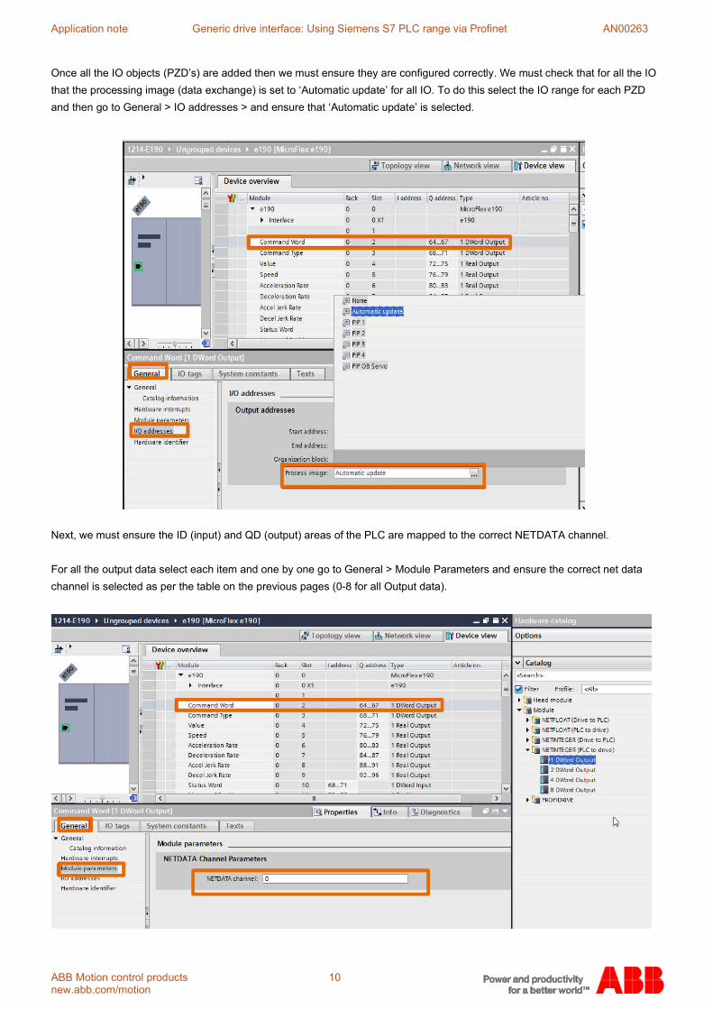
Once all the IO objects (PZD’s) are added then we must ensure they are configured correctly. We must check that for all the IO
that the processing image (data exchange) is set to ‘Automatic update’ for all IO. To do this select the IO range for each PZD
and then go to General > IO addresses > and ensure that ‘Automatic update’ is selected.
Next, we must ensure the ID (input) and QD (output) areas of the PLC are mapped to the correct NETDATA channel.
For all the output data select each item and one by one go to General > Module Parameters and ensure the correct net data
channel is selected as per the table on the previous pages (0-8 for all Output data).

Application note Generic drive interface: Using Siemens S7 PLC range via Profinet AN00263
ABB Motion control products 11 www.abb.com/motion
For all the Input data select each item and one by one go to General > Module Parameters and ensure the correct net data
channel is selected as per the table on the previous pages (100-106 for all Output data).
Downloading the configuration to the PLC
After we have configured the IO data that will be expected by the PLC, we must download this configuration to the PLC so we
can check the operation of the network. To do this we must first compile all of our hardware changes using the ‘compile’ button
then go ‘online’ to the PLC in question. The first time we select ‘go online’ TIA portal will automatically give a dialog box which
we can use to select the PLC we need to connect to. We must first ensure we select the correct network adapter then we can
scan for the PLC. TIA portal will use a mac scan feature to connect the PLC so ensure any antivirus software you have is
disabled and scanning is allowed.

Application note Generic drive interface: Using Siemens S7 PLC range via Profinet AN00263
ABB Motion control products 12 new.abb.com/motion
Once we are online you can download the configuration to the PLC by selecting ‘Download to device’, once you have found and
selected the PLC you want to connect to select ‘Load’.
Once downloaded and online we can use the ‘Devices’ view in the left-hand window to determine the status of the system. This
will show us any errors with the configuration. The PLC and MicroFlex e190 drive both have green tick icons, which means they
are connected properly.
If there is a problem a red cross will appear next to the devices that are not connected or configured correctly. If this happens
check for problems such as an incorrect version of GSDML file is used, addresses or names of devices selected or firmware
versions of the drive or PLC.
If you have any network issues you can use the Online access group in the ‘Devices’ window to get more information on the
system status.

Application note Generic drive interface: Using Siemens S7 PLC range via Profinet AN00263
ABB Motion control products 13 www.abb.com/motion
Downloading to the PLC and Data watch for debugging in the PLC
For us to check the status of the communications while debugging it may be useful to add a method of viewing the variables in
both the PLC and Mint Workbench. Once these variables have been mapped we are free to use them inside a program, but it
makes sense to include them in a watch table to aide debugging in the long run. Any variable that exists within a program can
be mapped into a watch list so we can map any of the variables we have just added for the e190 into a new watch list. To do
this we must first go offline so that we can set up a data monitoring ‘watch table’ for debugging.
To create a watch table we must first go to the devices view and select [PLC Name] > Watch and force tables > Add new watch
table. It will automatically be given a name for example Watch_Table_1’.
We can then add the currently mapped data for the drive node(s) by adding elements into the watch list then selecting the
address in the address column.
We can then go Online and monitor the data in the watch table located in [PLC Name] > Watch and force tables >
Watch_Table_1. Once complete you can use the ‘view online’ button to monitor the variables value.
Note: The column ‘Monitor value’ will display the current value of the variable (which should be formatted to the correct data
type). Consistent data values indicate PROFINET IO communication is normal.

Application note Generic drive interface: Using Siemens S7 PLC range via Profinet AN00263
ABB Motion control products 14 new.abb.com/motion
Data watch for debugging in the Drive
Now we have the facility to monitor the data in the PLC we can also set up data monitoring in the drive to check for consistency
of data. To do this we must go to our Mint Workbench session and go to the Edit and Debug part of the toolbox;
Next go to the ‘Spy’ window and select the ‘Data watch’ tab.
We can then add data here using the table shown earlier to select the correct data types for each net data location. To do this
select the ‘+++’ icon in the Spy window.
A box will then appear where you can select the Netdata you which will be added to the ‘Data watch list’. We should add the
data areas one at a time according to the table mentioned previously on page 8, selecting the correct address (Mint NetData
Channel) and the correct format (data type);
Once all the addresses are added you should have Netdata index 0 to 8 and NetData Index 100 to 106 mapped. Double check
all of the data formats (integer / float) are correct as per the table on page 8. To make it easier to keep track of the variables it’s
a good idea to rename the variables as per their function within the GDI. You can change the descriptions of the variables by
clicking on their description and typing the relevant name (see Application note AN00204 Mint for more detail).

Application note Generic drive interface: Using Siemens S7 PLC range via Profinet AN00263
ABB Motion control products 15 www.abb.com/motion
Introduction to the ABB Motion GDI library
To make the use of the Mint GDI easier for the user, ABB have created a library of function blocks which offer an easy method
to issue motion commands to the drive from the PLC. The library is included with this application note and can be imported into
your program easily to give you easy to use commands to achieve simple single axis motion.
Overview of the library instructions.
The library with this application note provides mechanisms for a Siemens PROFINET IO equipped PLC to:
Issue a home command Issue a command to detect a physical axis end stop and use this as a datum position (firmware version 5868
onwards required if using e190 or e180 drives) Issue a relative move Issue an absolute move Issue an incremental relative move (and optionally stop a programmed distance past a “fast-capture” position) Issue an incremental absolute move (and optionally stop a programmed distance past a “fast-capture” position) Setup an offset target for an incremental move (i.e. position the axis relative to a captured fast interrupt) Jog the axis Set the axis position Issue a speed reference Issue a torque reference Enable/disable the axis Enable/disable hardware limits Reset axis errors Perform a controlled stop or crash stop on the axis Gear the axis to a secondary encoder input Set speed, acceleration times, deceleration times and jerk times for all motion Control modulo or non-modulo axes
At the same time the PLC is able to monitor status information from the drive including:
Enabled state Ready to be enabled state Idle state In Position state Motor brake state Homed state Forward limit state Reverse limit state Fault state Stop input state Indication of missing fast latch interrupt Phase search status Error code Measured position Measured velocity Following error Axis mode of operation RMS current
This is all achieved via, what appears to the PLC as, input and output registers. Watchdog
An optional watchdog mechanism is also included, allowing the drive to take action (crash stop and disable by default) in the event of communication loss.

Application note Generic drive interface: Using Siemens S7 PLC range via Profinet AN00263
ABB Motion control products 16 new.abb.com/motion
Importing the User Defined Data Types and Library Instructions
Ensure the PLC is expanded in the ‘Devices’ window on the left so you can access the ‘program blocks’ and ‘PLC data types’
folders. Next we must select the ‘Libraries’ view, (selected from the right of the window) then click on the icon to ‘Open a Global
library’…
Next navigate to where you have saved the library and locate the file; ‘ABB Motion GDI library.al14’ and open it. This will then import the master copies of all the data to the project. Then all you need to do is drag the elements you need into the project folders;
If you import ‘Entire Program blocks Library’ into the ‘Program blocks’ folder you will automatically have all of the GDI blocks at your disposal. If you just want to use some of the library blocks then you can import them one at a time from the ‘Library Instructions’ directory. All five of the data types will need to be imported in all circumstances. Next the code must be compiled;

Application note Generic drive interface: Using Siemens S7 PLC range via Profinet AN00263
ABB Motion control products 17 www.abb.com/motion
Once your code is compiled TIA Portal will have access to all the data types and blocks that have been imported. The project now contains data types for the GDI axis (TGDIAxisRef) as well as data types for the command and status words used by this axis and the Input and Output structures
You will see that included in the Library is an example global variables list called ‘GDI_Global_Variables’. This gives a template that can be followed for adding further axes to the system. It contains a variable called ‘Axis1’ which is of data type ‘TGDIAxisRef’ for passing the data for “Axis1” between the GDI control and interface blocks. For further axes you can add more variables of data type ‘TGDIAxisRef’ into this data block structure for each additional axis. You will also see there is a variable called ‘WatchdogTime’ of type ‘time’. This variable defines the cycle time of the watchdog pulses sent from the PLC to the drive. The watchdog in the PLC will be active if you use it or not.
Mapping the data from the drive to the PLC
Before we start using the program we must create the data link between the drive IO and the datatypes the program expects to see. To do this we must check the addresses TIA portal has assigned to the e190 drives and then create a tag list that lists this information. To check the addresses assigned to the drive you must check by selecting ‘Device configuration’ check, ‘Device view’ is selected and pick the e190 from the drop down menu. As you can see below the first output address is QW0 and the first input address is IW0.
Next we must create a PLC Tags list that includes these declarations of the addresses using the data types “AxisInputs” for inputs and “AxisOutputs” for outputs. These special data types are structures which allow all of the variables from the drive to be read in at once just using a pointer to the start address of the drives inputs or outputs. We must enter input “start” address %I0.0, select the data type as ‘AxisInputs’ and give it a name (in the example below ‘Axis1DataIn’). Similarly, for the outputs, select ‘AxisOutputs’ as the data type, enter %Q0.0 as the “start” address and give it a name (in the example below ‘Axis1DataOut’).
Note: In the library there is an example of this in the AxisIOVariables folder called ‘AxisIOVariables’.

Application note Generic drive interface: Using Siemens S7 PLC range via Profinet AN00263
ABB Motion control products 18 new.abb.com/motion
Writing the program
We are now ready to start using these instructions to create some motion in our PLC application. For each axis we must add an axis reference to associate the control data from the function blocks to the PZD data which will be passed over PROFINET to the drive. In the below example we have created a ‘GDI_Global_Variables’ data block (DB100) to map all of the data for this and any further axes we will add to the program. For the first drive an entry has been created called ‘Axis1’ of Data Type ‘TGDIAxisRef’ (data type which was imported earlier). It’s also a good idea to add some information into the comments about the axis application;
Note: ‘Axis 1’ is how we will reference the axis/drive from in the program via GDI_Global_Variables.Axis1’
We now need to include an instance of the GDI_DATAINTERFACE_PNET function for each axis in our application. For this application note we will use the Main Routine (OB1) for our program logic. We have used ladder (LDR) for this example. Select the first rung and, using the instruction toolbox, add a new ‘Empty box’ Click on the ‘??’ in the box and type the name of the block you want. In this case GDI_DATAINTERFACE_PNET then press enter or select from the list. Once you have done this the ‘Call options’ box will appear to assist you in selecting the Data block address for this instance of the block. You can change the name here if you want, you can also manually select the data block address if you need to do so. The easiest method is to leave address assignation to Automatic and change the name of the block to reference the axis. For example ‘GDI_DATAINTERFACE_PNET_AXIS1’. Once finished – select ‘OK’;

Application note Generic drive interface: Using Siemens S7 PLC range via Profinet AN00263
ABB Motion control products 19 www.abb.com/motion
We now need to link the communication block’s input and output images to the input and output assemblies for our PROFINET IO drive. Double-click on the ‘…’ next to “Ptr_In” and then click on the ‘page’ icon and select the drive input data; ‘Axis1DataIn’ – this will then automatically assign a pointer to this (for the input it will be P#I0.0). Similarly for the outputs you must add the ‘Axis1DataOut’ to the ‘Ptr_Out’ output (again this will be assigned by a pointer in this case P#Q0.0). Next we can assign the axis reference to the communications block. To do this we should select Axis1 from our ‘GDI_Global_Variables’ list we created earlier. In this case the axis is Axis1 (though other axes can be added to the list as well). We can now download this to the PLC and test that we have basic communications operating correctly.

Application note Generic drive interface: Using Siemens S7 PLC range via Profinet AN00263
ABB Motion control products 20 new.abb.com/motion
GDI Function Blocks
The following sections detail the use of the GDI function blocks:
GDI_POWER
This function block is used to enable / disable an axis. The enable input enables the power stage in the drive and not the function block itself.
GDI_HOME
GDI_FIND_END_STOP
This function block is used as an alternative way to datum an axis in the absence of a home sensor. The axis will run at a commanded velocity with a programmed torque limit until this torque limit is reached and the speed of the axis is less than the programmed idle velocity. The Position input is used to set the axis position at the end of a successful datum sequence.
Type Description
VAR_IN_OUT
Axis TGDI_AxisRef Reference to the axis structure
VAR_INPUT Execute BOOL Start the datum sequence on a rising edge
Position REAL Absolute position to be set at the end of a successful datum sequence
FindSpeed REAL Speed in user units/sec (the sign of this value determines the seek direction)
FindAccel REAL Accel rate in user units/sec2
FindDecel REAL Decel rate in user units/sec2
FindAccelJerk REAL Accel jerk rate in user units/sec3 (set to 0 for trapezoidal motion)
FindDecelJerk REAL Decel jerk rate in user units/sec3 (set to 0 for trapezoidal motion)
TorqueLimit REAL Torque limit to apply during sequence (% of drive rated current) VAR_OUTPUT
Done BOOL Indicates that the axis has found the end stop successfully. If the Execute input is removed during the sequence and the axis finds the end stop the Done output will be set for one PLC scan. If the Execute input remains 1 then the Done output will also remain set (providing the sequence was successful)
Busy BOOL Set true whilst the find sequence is in progress Error BOOL Set true if the axis is in error
ErrorID DINT Indicates the Mint error code reported – See Section Error Handling
Type Description
VAR_IN_OUT
Axis TGDI_AxisRef Reference to the axis structure
VAR_INPUT Enable BOOL Whilst true the PLC will request the axis to be enabled
EnablePosNeg BOOL Whist true motion in both directions is permitted. If false motion is prevented (or a stop is performed if motion is already in progress)
VAR_OUTPUT Status BOOL Indicates whether the axis is enabled (1) or not (0)
Error BOOL Set to true if the axis is in error
ErrorID DINT Indicates the Mint error code reported – See Section Error Handling
ErrorDesc String Indicates the Mint error code Description in plain text
This function block is used to datum an axis. The details of the datum sequence are dependent on the Home type set in the Mint GDI program. The Position input is used to set the axis position at the end of a successful datum sequence.
Type Description
VAR_IN_OUT
Axis TGDI_AxisRef Reference to the axis structure
VAR_INPUT
Execute BOOL Start the datum sequence on a rising edge Position REAL Absolute position to be set at the end of a successful datum sequence
HomeSpeed REAL Homing speed in user units/sec
HomeAccel REAL Homing accel rate in user units/sec2
HomeDecel REAL Homing decel rate in user units/sec2
HomeAccelJerk REAL Homing accel jerk rate in user units/sec3 (set to 0 for trapezoidal motion)
HomeDecelJerk REAL Homing decel jerk rate in user units/sec3 (set to 0 for trapezoidal motion)
HomeBackOff REAL Ratio of Home speed to backoff speed VAR_OUTPUT
Done BOOL Indicates that the axis has homed successfully. If the Execute input is removed during homing and the axis completes the home sequence the Done output will be set for one PLC scan. If the Execute input remains 1 then the Done output will also remain set (providing the home was successful)
Busy BOOL Set true whilst the homing sequence is in progress
Error BOOL Set true if the axis is in error
ErrorID DINT Indicates the Mint error code reported – See Section Error Handling

Application note Generic drive interface: Using Siemens S7 PLC range via Profinet AN00263
ABB Motion control products 21 www.abb.com/motion
GDI_MOVERELATIVE
This function block is used to command a controlled motion of a specified distance relative to the start position.
GDI_MOVEABSOLUTE
This function block is used to command a controlled motion to a specified absolute position. This function can be used with Modulo axes (in which case the shortest route to the specified position will be taken).
Type Description
VAR_IN_OUT Axis TGDI_AxisRef Reference to the axis structure
VAR_INPUT
Execute BOOL Start the motion on a rising edge
Distance REAL Relative distance for the move (in user units)
Velocity REAL Maximum speed (not necessarily reached) in user units/sec Accel REAL Accel rate in user units/sec2
Decel REAL Decel rate in user units/sec2
AccelJerk REAL Accel jerk rate in user units/sec3 (0 for trapezoidal motion)
DecelJerk REAL Decel jerk rate in user units/sec3 (0 for trapezoidal motion)
VAR_OUTPUT Done BOOL Indicates that the axis has reached the target position successfully. If
the Execute input is removed during motion and the relative move completes the Done output will be set 1 for one PLC scan. If the Execute input remains True then the Done output will also remain set (providing the target position was successfully achieved)
Busy BOOL Set True whilst the relative move is in progress Error BOOL Set True if the axis is in error
ErrorID DINT Indicates the Mint error code reported – See Section Error Handling
Type Description
VAR_IN_OUT
Axis TGDI_AxisRef Reference to the axis structure VAR_INPUT
Execute BOOL Start the motion on a rising edge
Position REAL Target position for the move (in user units)
Velocity REAL Maximum speed (not necessarily reached) in user units/sec
Accel REAL Accel rate in user units/sec2 Decel REAL Decel rate in user units/sec2
AccelJerk REAL Accel jerk rate in user units/sec3 (0 for trapezoidal motion)
DecelJerk REAL Decel jerk rate in user units/sec3 (0 for trapezoidal motion)
ModuloAxis BOOL Defines whether the axis is a modulo axis (i.e. using an ENCODERWRAP to define travel within one cycle). Absolute moves when using modulo axes are always implemented via the shortest path (e.g. an absolute move to 20 degrees from 350 degrees on a 0-360 degree modulo axis will result in forward travel of 30 degrees)
VAR_OUTPUT
Done BOOL Indicates that the axis has reached the target position successfully. If the Execute input is removed during motion and the absolute move completes the Done output will be set True for one PLC scan. If the Execute input remains True then the Done output will also remain set (providing the target position was successfully achieved)
Busy BOOL Set True whilst the absolute move is in progress
Error BOOL Set True if the axis is in error
ErrorID DINT Indicates the Mint error code reported – See Section Error Handling

Application note Generic drive interface: Using Siemens S7 PLC range via Profinet AN00263
ABB Motion control products 22 new.abb.com/motion
GDI_INCR
This function block is used to command a controlled motion of a specified distance relative to the target position at the time of
the execution. The target position resulting from a call to this function block can be modified whilst motion is still in progress by
any of the following methods:
a. By issuing another GDI_INCR or GDI_INCA function (providing input parameter BufferMode is True)
b. By setting the input parameter Latchmode to True and specifying a value for the input parameter LatchOffset. Mint
code on the drive will then automatically modify the axis target position such that it stops the LatchOffset distance past
the axis position captured by the defined fast interrupt. A bit within the Axis status word (btLatchMissed) is available to
indicate failure to detect this fast interrupt (this condition may then be used to alert the operator to a system failure for
example). Using Latchmode and LatchOffset allows simple implementation of indexing conveyor applications.
GDI_INCR is also useful if the application needs to modify SPEED/ACCEL/DECEL of a relative move already in progress. Moves loaded using GDI_MOVERELATIVE are profiled using the SPEED/ACCEL/DECEL loaded at the time and these cannot be changed once the move has started. By using GDI_INCR with the input parameter BufferMode set True then it is possible to modify the profile parameters by loading another GDI_INCR (with new SPEED/ACCEL/DECEL) with input parameter Distance set to zero.
Type Description
VAR_IN_OUT Axis TGDI_AxisRef Reference to the axis structure
VAR_INPUT
Execute BOOL Start the motion on a rising edge
Distance REAL Relative distance for the move (in user units)
Velocity REAL Maximum speed (not necessarily reached) in user units/sec Accel REAL Accel rate in user units/sec2
Decel REAL Decel rate in user units/sec2
AccelJerk REAL Accel jerk rate in user units/sec3 (0 for trapezoidal motion)
DecelJerk REAL Decel jerk rate in user units/sec3 (0 for trapezoidal motion)
LatchMode BOOL Sets whether the axis should utilise the configured fast latch interrupt and set a new target position ‘LatchOffset’ user units past the captured position
LatchOffset REAL Defines the distance past the captured fast position (in user units) the target for GDI_INCR should be modified by (when input parameter LatchMode is set True)
BufferMode BOOL Defines whether the function block should set the Done output and complete as soon as the move has been loaded. Setting BufferMode True allows the application to trigger further incremental moves whilst existing moves are in progress
VAR_OUTPUT
Done BOOL When BufferMode is set False this indicates that the axis has reached the target position successfully. If the Execute input is removed during motion and the relative move completes the Done output will be set True for one PLC scan. If the Execute input remains True then the Done output will also remain set (providing the target position was successfully achieved). When BufferMode is set True the Done output is set for one PLC scan to indicate successful loading of the move
Busy BOOL Set True whilst the function block is in progress
Error BOOL Set True if the axis is in error
ErrorID DINT Indicates the Mint error code reported – See Section Error Handling
Application note Generic drive interface: Using Siemens S7 PLC range via Profinet AN00263
ABB Motion control products 23 www.abb.com/motion
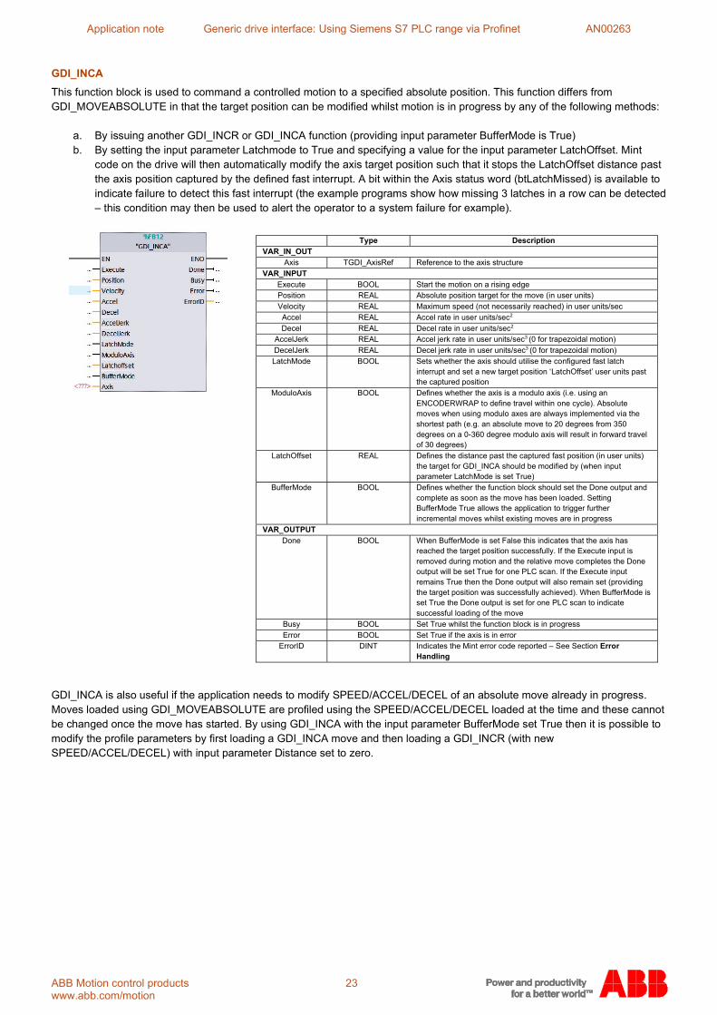
GDI_INCA
This function block is used to command a controlled motion to a specified absolute position. This function differs from GDI_MOVEABSOLUTE in that the target position can be modified whilst motion is in progress by any of the following methods:
a. By issuing another GDI_INCR or GDI_INCA function (providing input parameter BufferMode is True) b. By setting the input parameter Latchmode to True and specifying a value for the input parameter LatchOffset. Mint
code on the drive will then automatically modify the axis target position such that it stops the LatchOffset distance past the axis position captured by the defined fast interrupt. A bit within the Axis status word (btLatchMissed) is available to indicate failure to detect this fast interrupt (the example programs show how missing 3 latches in a row can be detected – this condition may then be used to alert the operator to a system failure for example).
GDI_INCA is also useful if the application needs to modify SPEED/ACCEL/DECEL of an absolute move already in progress. Moves loaded using GDI_MOVEABSOLUTE are profiled using the SPEED/ACCEL/DECEL loaded at the time and these cannot be changed once the move has started. By using GDI_INCA with the input parameter BufferMode set True then it is possible to modify the profile parameters by first loading a GDI_INCA move and then loading a GDI_INCR (with new SPEED/ACCEL/DECEL) with input parameter Distance set to zero.
Type Description
VAR_IN_OUT
Axis TGDI_AxisRef Reference to the axis structure
VAR_INPUT
Execute BOOL Start the motion on a rising edge Position REAL Absolute position target for the move (in user units)
Velocity REAL Maximum speed (not necessarily reached) in user units/sec
Accel REAL Accel rate in user units/sec2
Decel REAL Decel rate in user units/sec2 AccelJerk REAL Accel jerk rate in user units/sec3 (0 for trapezoidal motion)
DecelJerk REAL Decel jerk rate in user units/sec3 (0 for trapezoidal motion)
LatchMode BOOL Sets whether the axis should utilise the configured fast latch interrupt and set a new target position ‘LatchOffset’ user units past the captured position
ModuloAxis BOOL Defines whether the axis is a modulo axis (i.e. using an ENCODERWRAP to define travel within one cycle). Absolute moves when using modulo axes are always implemented via the shortest path (e.g. an absolute move to 20 degrees from 350 degrees on a 0-360 degree modulo axis will result in forward travel of 30 degrees)
LatchOffset REAL Defines the distance past the captured fast position (in user units) the target for GDI_INCA should be modified by (when input parameter LatchMode is set True)
BufferMode BOOL Defines whether the function block should set the Done output and complete as soon as the move has been loaded. Setting BufferMode True allows the application to trigger further incremental moves whilst existing moves are in progress
VAR_OUTPUT
Done BOOL When BufferMode is set False this indicates that the axis has reached the target position successfully. If the Execute input is removed during motion and the relative move completes the Done output will be set True for one PLC scan. If the Execute input remains True then the Done output will also remain set (providing the target position was successfully achieved). When BufferMode is set True the Done output is set for one PLC scan to indicate successful loading of the move
Busy BOOL Set True whilst the function block is in progress
Error BOOL Set True if the axis is in error ErrorID DINT Indicates the Mint error code reported – See Section Error
Handling

Application note Generic drive interface: Using Siemens S7 PLC range via Profinet AN00263
ABB Motion control products 24 new.abb.com/motion
GDI_JOG
This function block is used to command a constant speed move on the axis (using the position loop controller in the drive). Motion is performed if the Execute input remains True and the JogSpeed is not ‘0’. A new execute command will be needed if the JogSpeed becomes ‘0’ as the axis will consider this as the end of the motion.
GDI_SETPOSITION
This function block is used to set the axis position (encoder and position values on the drive) to a programmed value. The axis must be idle when this function is called, otherwise the axis will return an “action not possible - motion in progress” error (Error code 10). If the axis is using an absolute encoder this will set/teach a new absolute position (GDI Mint program v2.17 onwards).
GDI_STOP
This function block is used to perform a controlled stop on the axis at the programmed deceleration rate.
Type Description
VAR_IN_OUT
Axis TGDI_AxisRef Reference to the axis structure
VAR_INPUT
Execute BOOL Set the new position on a rising edge
Position REAL Value for the axis position to be set (in user units)
VAR_OUTPUT
Done BOOL Set True as soon as the command has been issued (regardless of whether it was successful or not – use the Error output to determine whether the command was successful). Remains True until the Execute input is removed. If the Execute input is removed before the Done bit is set then the Done bit will be set for a single PLC cycle.
Busy BOOL Set True whilst the function block is in progress (cleared once the Done bit is set)
Error BOOL Set True if the axis is in error
ErrorID DINT Indicates the Mint error code reported – See Section Error Handling
Type Description
VAR_IN_OUT
Axis TGDI_AxisRef Reference to the axis structure VAR_INPUT
Execute BOOL Start the controlled stop on a rising edge
Decel REAL Decel rate in user units/sec2
DecelJerk REAL Decel jerk rate in user units/sec3 (0 for trapezoidal motion)
VAR_OUTPUT Done BOOL Set True when the axis becomes idle after completing the controlled
stop or if an error occurs when the stop command is issued. Remains True until the Execute input is removed. If the Execute input is removed before the Done bit is set then the Done bit will be set for a single PLC cycle.
Busy BOOL Set True whilst the stop is in progress – cleared once the Done bit is set
Error BOOL Set True if the axis is in error
ErrorID DINT Indicates the Mint error code reported – See Section Error Handling
Type Description
VAR_IN_OUT
Axis TGDI_AxisRef Reference to the axis structure
VAR_INPUT
Execute BOOL Start the motion on a rising edge and maintain motion as long as the input remains True. Motion ramps to zero speed at the configured Decel rate when Execute becomes False
JogSpeed REAL Value for the speed the axis will reach in user units/sec Accel REAL Accel rate in user units/sec2
Decel REAL Decel rate in user units/sec2
AccelJerk REAL Accel jerk rate in user units/sec3 (0 for trapezoidal motion)
DecelJerk REAL Decel jerk rate in user units/sec3 (0 for trapezoidal motion)
VAR_OUTPUT Done BOOL Set True as soon as the Jog command has been successfully issued
and remains set until Execute becomes False or an axis error occurs
Busy BOOL Set True whilst the function block is in progress. Will be on if the block is executed but JogSpeed = 0
Error BOOL Set True if the axis is in error
ErrorID DINT Indicates the Mint error code reported – See Section Error Handling

Application note Generic drive interface: Using Siemens S7 PLC range via Profinet AN00263
ABB Motion control products 25 www.abb.com/motion
GDI_CLEAR
This function block is used to crash stop the axis and interrupt any motion that is in progress. The axis will remain enabled (providing GDI_POWER is requesting the enabled state and the axis is not in error).
GDI_RESET
This function block is used to reset any axis error that is present
GDI_SPEEDREF
This function block is used to command a speed/velocity reference on the axis. In this mode of operation the position loop is not used on the drive (so no following error is recorded or acted upon). The axis will remain in Speed control mode (as indicated by the Statusword bits for Controlmode) until motion of another control mode type is issued (e.g. a position controlled move). To switch from zero speed operation (in speed control mode) to holding position (in position control mode) a GDI_MOVERELATIVE could be issued, for example, with a relative move distance of zero user units
Type Description VAR_IN_OUT
Axis TGDI_AxisRef Reference to the axis structure
VAR_INPUT
Execute BOOL Start the crash stop on a rising edge
VAR_OUTPUT Done BOOL Set True when the axis becomes idle after completing the crash stop
or if an error occurs when the crash stop command is issued. Remains True until the Execute input is removed. If the Execute input is removed before the Done bit is set then the Done bit will be set for a single PLC cycle.
Busy BOOL Set True whilst the stop is in progress – cleared once the Done bit is set
Error BOOL Set True if the axis is in error
ErrorID DINT Indicates the Mint error code reported – See Section Error Handling
Type Description
VAR_IN_OUT
Axis TGDI_AxisRef Reference to the axis structure
VAR_INPUT
Execute BOOL Start the fault reset on a rising edge
VAR_OUTPUT
Done BOOL Set True when the axis no longer has an error present. Remains True until the Execute input is removed. If the Execute input is removed before the Done bit is set then the Done bit will be set for a single PLC cycle. The Done bit will not be set if the error could not be cleared (use the Busy output to detect when the fault reset has been attempted)
Busy BOOL Set True whilst the function block is attempting to clear any axis error
Error BOOL Set True if the axis is in error
ErrorID DINT Indicates the Mint error code reported – See Section Error Handling
Type Description VAR_IN_OUT
Axis TGDI_AxisRef Reference to the axis structure
VAR_INPUT
Execute BOOL Start the axis on a rising edge and maintain motion as long as the input remains True. Motion ramps to zero speed at the configured Decel rate when Execute becomes False
Speed REAL Value for the speed the axis will reach in user units/sec. Can be modified whilst Execute is True to change the axis speed
Accel REAL Accel rate in user units/sec2
Decel REAL Decel rate in user units/sec2
VAR_OUTPUT
Done BOOL Set True as soon as the speed reference has been issued (regardless of whether it was successful or not). The Done output remains set until Execute becomes False
Busy BOOL Set True whilst the function block is in progress (i.e. whilst Execute is True)
Error BOOL Set True if the axis is in error
ErrorID DINT Indicates the Mint error code reported – See Section Error Handling

Application note Generic drive interface: Using Siemens S7 PLC range via Profinet AN00263
ABB Motion control products 26 new.abb.com/motion
GDI_TORQUEREF
This function block is used to command a torque (current) reference on the axis. In this mode of operation the position loop is not used on the drive (so no following error is recorded or acted upon). The axis will remain in torque control mode (as indicated by the Statusword bits for Controlmode) until motion of another control mode type is issued (e.g. a position controlled move). To switch from zero torque operation (in torque control mode) to holding position (in position control mode) an GDI_MOVERELATIVE could be issued, for example, with a relative move distance of zero user units.
GDI_FOLLOW
This function block is used to command the axis to start following the configured master encoder reference at the programmed follow ratio.
Type Description
VAR_IN_OUT
Axis TGDI_AxisRef Reference to the axis structure
VAR_INPUT
Execute BOOL Start the torque reference on a rising edge and maintain torque as long as the input remains True. Torque ramps to zero at the configured FallTime rate when Execute becomes False
Torque REAL Value for the torque reference the axis will use (in % of DRIVERATEDCURRENT – see Mint Help file). Can be modified whilst Execute is True to change the torque produced
SpeedLimit REAL While using Torque control its possible to impose a maximum speed that the motor is allowed to run at. This stops the motor “running away” if the opposing torque is easily overcome by the motors set point. The default of this input is set to 1000 user velocity units so as not to get in the way if this function is not needed.
RiseTime REAL Sets the time taken (in ms) for current to rise from zero to DRIVEPEAKCURRENT (see Mint Help file)
FallTime REAL Sets the time taken (in ms) for current to fall from DRIVEPEAKCURRENT to zero (see Mint Help file)
VAR_OUTPUT
Done BOOL Set True as soon as the torque reference has been issued (regardless of whether it was successful or not). The Done output remains set until Execute becomes False
Busy BOOL Set True whilst the function block is in progress (i.e. whilst Execute is True)
Error BOOL Set True if the axis is in error
ErrorID DINT Indicates the Mint error code reported – See Section Error Handling
Type Description
VAR_IN_OUT
Axis TGDI_AxisRef Reference to the axis structure
VAR_INPUT
Execute BOOL Start the follow on a rising edge. The axis will remain in follow mode when the Execute input becomes False (to stop the follow issue another motion command or clear motion using GDI_CLEAR)
Ratio REAL Value for the follow (gear) ratio between the axis and the master encoder reference (the value will affected by the scaling of the axis and the scaling of the master encoder – see the Mint Help file topic for FOLLOW). To set a new ratio whilst following it is necessary to issue a new GDI_FOLLOW command
VAR_OUTPUT
Done BOOL Set True as soon as the follow has been issued (regardless of whether it was successful or not). The Done output remains set until Execute becomes False
Busy BOOL Set True whilst the function block is in progress (i.e. whilst Execute is True)
Error BOOL Set True if the axis is in error
ErrorID DINT Indicates the Mint error code reported – See Section Error Handling

Application note Generic drive interface: Using Siemens S7 PLC range via Profinet AN00263
ABB Motion control products 27 www.abb.com/motion
GDI_DATAINTERFACE_PNET
This function block is used to transfer command/status data between the application layer and the communication layer of the PLC program. An instance of the relevant function block must exist for each axis in the application
Type Description
VAR_INPUT
Ptr_In “AxisInputs” – will use a pointer to reference 40Bytes
of Input data
Reference to the input structure for the axis
VAR_OUTPUT
Ptr_Out “AxisOutputs” – will use a pointer to reference 40Bytes
of Output data
Reference to the output structure for the axis
VAR_IN_OUT
Axis TGDI_AxisRef Reference to the axis structure
Application note Generic drive interface: Using Siemens S7 PLC range via Profinet AN00263
ABB Motion control products 28 new.abb.com/motion
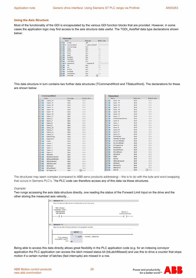
Using the Axis Structure
Most of the functionality of the GDI is encapsulated by the various GDI function blocks that are provided. However, in some cases the application logic may find access to the axis structure data useful. The TGDI_AxisRef data type declarations shown below:
This data structure in turn contains two further data structures (TCommandWord and TStatusWord). The declarations for these are shown below:
he PLC code can therefore access any of this data via these structures.
Two rungs accessing the axis data structure directly, one reading the status of the Forward Limit Input on the drive and the other storing the measured axis velocity…
Being able to access this data directly allows great flexibility in the PLC application code (e.g. for an indexing conveyor application the PLC application can access the latch missed status bit (btLatchMissed) and use this to drive a counter that stops motion if a certain number of latches (fast interrupts) are missed in a row.

Application note Generic drive interface: Using Siemens S7 PLC range via Profinet AN00263
ABB Motion control products 29 www.abb.com/motion
Communication Watchdog
The watchdog mechanism toggles a bit in the control word (generated by the GDI_DATAINTERFACE_PNET block) on for 250ms and then off for 250ms repeatedly to show the drive that it still has communications with the master control PLC. The change of state of this block must be detected by the drive at a rate of less than to the mint variable ‘_nWatchdogTime’ which is set to 1000ms as default. If it detects a loss of communication, then the drive will automatically crash stop. The user can change the value of the watchdog time by editing line 133 in the mint code to a new value but must not be less than 2 times the watchdog toggle time that is used in the PLC library. As default it is set to 1000ms;
‘Const _nWatchdogTime As Integer = 1000 'ms’ The user can enable or disable this feature of the GDI by setting a mint variable (on line 132 of the mint code);
‘_bUseWatchdog = _true’ OR ‘_bUseWatchdog = _false’.
Error Handling If any block makes the drive go into error, the block in question will show “Done” and “Error” outputs = TRUE. The “ErrorID” output will also give the current error which corresponds to the drive Error code.
Error Code
Description
40 Axis is not enabled
Application note Generic drive interface: Using Siemens S7 PLC range via Profinet AN00263
ABB Motion control products 30 new.abb.com/motion
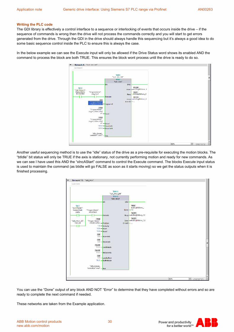
Writing the PLC code The GDI library is effectively a control interface to a sequence or interlocking of events that occurs inside the drive – if the sequence of commands is wrong then the drive will not process the commands correctly and you will start to get errors generated from the drive. Through the GDI in the drive should always handle this sequencing but it’s always a good idea to do some basic sequence control inside the PLC to ensure this is always the case. In the below example we can see the Execute input will only be allowed if the Drive Status word shows its enabled AND the command to process the block are both TRUE. This ensures the block wont process until the drive is ready to do so.
Another useful sequencing method is to use the “idle” status of the drive as a pre-requisite for executing the motion blocks. The “btIdle” bit status will only be TRUE if the axis is stationary, not currently performing motion and ready for new commands. As we can see I have used this AND the “xIncAStart” command to control the Execute command. The blocks Execute input status is used to maintain the command (as btidle will go FALSE as soon as it starts moving) so we get the status outputs when it is finished processing.
You can use the “Done” output of any block AND NOT “Error” to determine that they have completed without errors and so are ready to complete the next command if needed. These networks are taken from the Example application.

Application note Generic drive interface: Using Siemens S7 PLC range via Profinet AN00263
ABB Motion control products 31 www.abb.com/motion
Example Application In addition to the library files included with this application note the download also includes an example PLC application. The example PLC application has an embedded watchdog in the ‘GDI_DATAINTERFACE_PNET’ function block rungs to illustrate direct axis structure and instances of every single GDI function block (the SIMATIC S7 data watch can be used to poke data into the relevant input parameters to exercise these functions).
New Modifications in ABB Motion GDI Library v1.3 Improvements in V1.3 of the library;
• Added Speed Limit input to GDI_TORQUEREF block • Corrected bug in GDI_SPEEDREF block so triggering is better and Speed reference can be changed without
retriggering • Project now contains HMI element which can be used in Simulation mode to ease commissioning
Improvements in V1.2 of the library;
• Added MC_Power “ErrorDesc” output to aid with debugging – this will give a description of the error as a string. • Changed ErrorID data type from Dword to Dint • Added control so jog block will now only start to process if JogSpeed NOT 0, though a return to 0 after this will
deactivate it. • Added Accel/Decel Jerk and Decel reissued once Jog is already running • GDIVelRef is the correct choice for joystick type applications but now GDI_Jog is better than before.
Contact us For more information please contact your local ABB representative or one of the following: new.abb.com/motion new.abb.com/drives new.abb.com/channel-partners new.abb.com/plc PROFINET IO is a trademark of the PROFINET Group.
TIA Portal, Simatic, and Step 7 are trademarks of Siemens AG.
© Copyright 2019 ABB. All rights reserved.
Specifications subject to change without notice.