an1002 quickreference interfacing peitel usb …. equals main firmware version, 6 digits . ccc....
TRANSCRIPT
PEI TEL Communications GmbHPotsdamer Str. 12 b, D-14513 Teltow, Tel: +49 3328 3516 0, Fax: +49 3328 3516 16, E-Mail: [email protected], www.peitel.de
Application Note 1002
Quickreference
Interfacing
PEI TEL USB Audio Devices
• PS12 USB family • PS20 USB family
Revision: 1.1
MAY 2010
Application Note 1002 Quickreference Interfacing PEI TEL USB Audio devices
Page 2 / 18
Contents
0. HISTORY ......................................................................................................................... 3
1. GENERAL ....................................................................................................................... 3 1.1 Disclaimer..........................................................................................................................................3 1.2 Related Documents ..........................................................................................................................3 1.3 References ........................................................................................................................................3 1.4 Introduction.......................................................................................................................................3 1.5 Getting on the USB...........................................................................................................................4 1.6 Type of Product ................................................................................................................................4
2. USB SOUND DEVICE ..................................................................................................... 5 2.1 Audio Signal Flow Chart ..................................................................................................................5 2.2 Windows® Mixer Panel ....................................................................................................................6 2.3 Windows® XP API for Sound devices ............................................................................................6 2.4 Windows® Vista/7 API for Sound devices .....................................................................................9
3. USB HID DEVICE.......................................................................................................... 10 3.1 Opening the Device ........................................................................................................................10 3.2 Reading and Writing Reports ........................................................................................................11
3.2.1 Writing Output Report .......................................................................................................................11 3.2.2 Reading Input Report........................................................................................................................12
3.3 Closing the Device..........................................................................................................................13 APPENDIX A-1: OUTPUTBYTE PS12................................................................................. 14
APPENDIX A-2: OUTPUTBYTE PS20................................................................................. 15
APPENDIX B-1: INPUTBYTE1 PS12 .................................................................................. 17
APPENDIX B-2: INPUTBYTE1 PS20 .................................................................................. 18

Application Note 1002 Quickreference Interfacing PEI TEL USB Audio devices
Page 3 / 18
0. HISTORY
Date Revision Author Comments
APR 2010 1.0 TS First Draft
MAY 2010 1.1 TS First Release
Table 1: History
1. GENERAL
1.1 DISCLAIMER All information and data contained in this data sheet are without any commitment, are not to be considered as an offer for conclusion of a contract, nor shall they be construed as to create any liability.
Any new issue of this Application Note invalidates previous issues. Further, PEI TEL Communications GmbH reserves the right to revise this publication and to make changes to its content, at any time, without obligation to notify any person or entity of such revisions or changes. No part of this publication may be reproduced, photocopied, stored on a retrieval system, or transmitted without the express written consent of PEI TEL Communications GmbH.
1.2 RELATED DOCUMENTS
Nr. Name Revision/Date Filename Comments
Table 2: Related Documents
1.3 REFERENCES
[1] USB specification, USB HID specification, USB HID usages tables, etc. www.usb.org
[2] MSDN Developer Center/Library http://msdn.microsoft.com/en-us/library
[3] USB Complete, Jan Axelson www.lvr.com
1.4 INTRODUCTION This document gives a quickreference of how to interface a PEI TEL USB Audio device of the type PS12 USB family and PS20 USB family by a user's application. Unlike the PS12 USB family the PS20 USB family has an integrated speaker.
A more detailed description is given in the document "AN1000 Interfacing PEI TEL USB Audio Devices". Windows® XP and Windows® 7 was used for this document, but should work for
Application Note 1002 Quickreference Interfacing PEI TEL USB Audio devices
Page 4 / 18
Windows® Vista similar. Special attention must be paid especially to the mixer functionality, which has changed considerably from Windows® XP to Windows® Vista/Windows® 7.
Furthermore, it is assumed that the reader is familiar with basic USB knowledge.
1.5 GETTING ON THE USB All required drivers will be installed automatically when plugged into a free USB port the first time. You will be notified when installation has been completed.
PEI TEL USB Audio devices will be recognized by Windows® Operating Systems as a Composite Device which consists of an USB Sound Device and a USB HID Device (Human Interface Device).
PEI TEL USB Audio devices use the following Vendor ID and Product ID:
• Vendor ID (VID): 0x074D
• Product ID (PID): 0x3576
All PEI TEL USB Audio devices do fully support Chapter 9 of the USB specification.
The PEI TEL USB HID devices do support a Control Endpoint (Endpoint 0) and an Interrupt IN Endpoint, since this is mandatory for all HID devices.
Since PEI TEL USB Audio devices are equipped differently, parts of this document may not be relevant. For instance, a PS12 USB does not have a speaker, hence adjusting speaker volume does not have an effect.
1.6 TYPE OF PRODUCT The device name (product name) of all PEI TEL USB Audio devices will always be read as "PTC USB". To determine the type of product the Serial Number String needs to be examined. The Serial Number String can be read via a call to the function HidD_GetSerialNumberString(). Special attention has to be paid, since the routine returns a NULL-terminated wide character string and must be converted to one byte ASCII (discard 2nd byte). The structure of the Serial Number String is as follows:
aaa.aaa.bbb.bbb.ccc.xxxxxx
where
aaa.aaa equals Hardware Version, 6 digits
bbb.bbb equals Main Firmware Version, 6 digits
ccc equals Type of Product, 3 digits
xxxxxx equals Serial number, 6 digits
The field "Type of Product, ccc" comprises of 3 digits and is coded as follows:
1st digit TYPE General type of device, i.e. PS12, PS20
2nd digit MAJOR Sub-Version, i.e. 1 button, 2 buttons, 1 LED, 2 LED, etc.
3rd digit MINOR Further subclassing if required, i.e. different SW versions

Application Note 1002 Quickreference Interfacing PEI TEL USB Audio devices
Page 5 / 18
Currently the following types are defined:
TYPE MAJOR MINOR
1 X X PS12
2 X X PS20
3 X X ME/TM
4 X X HA-AXX
5 X X DK-USB-Modul
Table 3: Coding of Field "Type of Product"
Examples:
PS12-Standard: 100 (existing, as of today)
PS20 Standard 200 (existing, as of today)
TM110 Standard 300 (planned, as of today)
ME110 Standard 310 (planned, as of today)
HA-A10 Standard 400 (planned, as of today)
Development-Kit-USB-Modul 500 (planned, as of today)
The list may be subject to be extended or shortened.
2. USB SOUND DEVICE Since the WINDOWS AUDIO MIXER is very complex, it is way beyond to describe all possibilities in this document. The PEI TEL USB Sound Device appears as an external sound card, which is usually automatically selected when plugged into the USB port.
So changing its volume levels (microphone and speaker) can be achieved by
• using standard Windows® API functions or
• manually through the Windows® Mixer Panel(s).
2.1 AUDIO SIGNAL FLOW CHART The following chart shows the Audio Signal Flow of a PEI TEL USB Audio device as implemented in the firmware.
USB-Upstream
(Audio to Host)
USB-Downstream
(Audio from Host)
OutputReportDMIC,HMIC = 1,0
DMIC,HMIC = 0,1
MUTE = 1
Vol Vol, Mute
SPK = 1
Master Playback
Vol, Mute
OutputReport
Master Recording (Wave In) Microphone
Desktop Microphone
Headset Microphone
Desktop Speaker
Headset Speaker
Figure 1: Audio Signal Flow of a fully equipped PEI TEL USB Audio device of PS20 USB family
Application Note 1002 Quickreference Interfacing PEI TEL USB Audio devices
Page 6 / 18
Remarks:
1. Some options may not be available on all devices, e.g. a PS12 USB does not have a speaker.
2. Since we are using the Windows® Standard Audio driver, additional controls depending on the hardware and/or software availability might be present, e.g. SW-Synthesizer or CD-Player.
3. Even if a PEI TEL USB Audio device is not equipped with a speaker, a Playback device is shown in the mixer panel. This is due to software compatibility to the Windows® Standard Audio driver. So for sound output an other sound device must be specified, e.g. the standard sound device. Please refer to the help of the Operating System to determine how to do this.
2.2 WINDOWS® MIXER PANEL The Mixer Panel may also be known as the Volume Control. The mixer panel is similar to those hardware mixers we are used to seeing in recording studios. Its main purpose is to route and adjust the volume from a variety of Input Devices which supply audio signals to possible Outputs. Input devices include CD Players, wav files, microphones, etc. The output is the sound output of the sound card that supplies audio to the speaker(s). Routing output to a PEI TEL USB Audio device can apply for obvious reasons only to those PEI TEL USB Audio devices equipped with speaker(s).
The Mixer Panel may be accessed by the small speaker icon in the system tray.
Figure 2: Speaker icon in system tray Windows® XP
Figure 3: Speaker icon in system tray Windows® Vista/7
2.3 WINDOWS® XP API FOR SOUND DEVICES Since the complexity of the Windows® XP API for mixer control, most users will use the existing controls. When setting up your application, we recommend to enumerate which audio lines and controls according to the audio signal flow chart (Figure 1) are recognized and supported by the Operating System. The mmsystem.dll is required for enumerating mixer(s). All definitions and declarations are contained in the header file mmsystem.h. Enumerating the mixer(s) requires usually the following 5 steps:
(1) Get Mixer ID, Name and Number of Destinations of mixer(s) Only mixer device(s) named "PTC USB" are of interest for us. Determine how many mixer devices are in the system by a call to mixerGetNumDevs(). The mixer ID(s) of the existing mixer(s) start with 0 and increment to one less than the returned value.
Use these mixer ID(s) to get information about the capabilities of the mixer device such as ist name and the number of destination lines by a call to mixerGetDevCaps(). This function fills a MIXERCAPS structure. If the szPname member does not give the name "PTC USB" move on to the next mixer device in the list. The number of destinations of that mixer is given by the cDestinations member of the MIXERCAPS structure.
Application Note 1002 Quickreference Interfacing PEI TEL USB Audio devices
Page 7 / 18
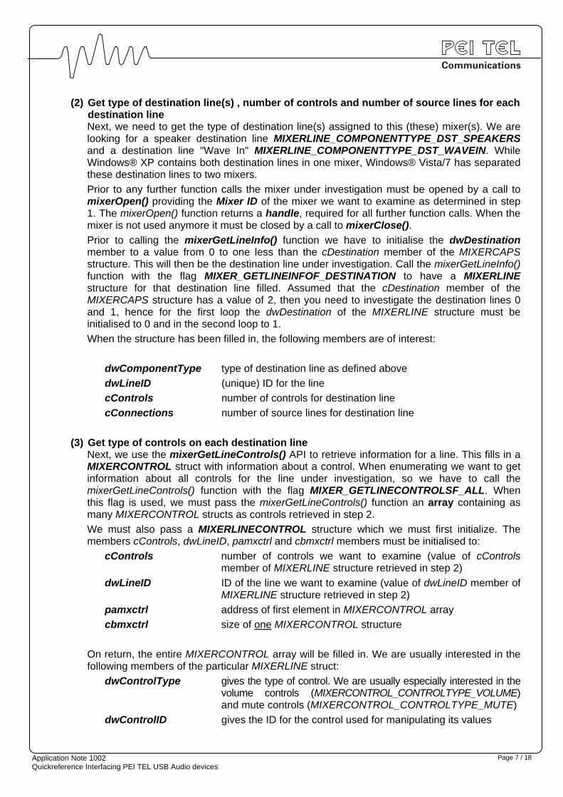
(2) Get type of destination line(s) , number of controls and number of source lines for each destination line Next, we need to get the type of destination line(s) assigned to this (these) mixer(s). We are looking for a speaker destination line MIXERLINE_COMPONENTTYPE_DST_SPEAKERS and a destination line "Wave In" MIXERLINE_COMPONENTTYPE_DST_WAVEIN. While Windows® XP contains both destination lines in one mixer, Windows® Vista/7 has separated these destination lines to two mixers.
Prior to any further function calls the mixer under investigation must be opened by a call to mixerOpen() providing the Mixer ID of the mixer we want to examine as determined in step 1. The mixerOpen() function returns a handle, required for all further function calls. When the mixer is not used anymore it must be closed by a call to mixerClose().
Prior to calling the mixerGetLineInfo() function we have to initialise the dwDestination member to a value from 0 to one less than the cDestination member of the MIXERCAPS structure. This will then be the destination line under investigation. Call the mixerGetLineInfo() function with the flag MIXER_GETLINEINFOF_DESTINATION to have a MIXERLINE structure for that destination line filled. Assumed that the cDestination member of the MIXERCAPS structure has a value of 2, then you need to investigate the destination lines 0 and 1, hence for the first loop the dwDestination of the MIXERLINE structure must be initialised to 0 and in the second loop to 1.
When the structure has been filled in, the following members are of interest:
dwComponentType type of destination line as defined above
dwLineID (unique) ID for the line
cControls number of controls for destination line
cConnections number of source lines for destination line
(3) Get type of controls on each destination line Next, we use the mixerGetLineControls() API to retrieve information for a line. This fills in a MIXERCONTROL struct with information about a control. When enumerating we want to get information about all controls for the line under investigation, so we have to call the mixerGetLineControls() function with the flag MIXER_GETLINECONTROLSF_ALL. When this flag is used, we must pass the mixerGetLineControls() function an array containing as many MIXERCONTROL structs as controls retrieved in step 2.
We must also pass a MIXERLINECONTROL structure which we must first initialize. The members cControls, dwLineID, pamxctrl and cbmxctrl members must be initialised to:
cControls number of controls we want to examine (value of cControls member of MIXERLINE structure retrieved in step 2)
dwLineID ID of the line we want to examine (value of dwLineID member of MIXERLINE structure retrieved in step 2)
pamxctrl address of first element in MIXERCONTROL array
cbmxctrl size of one MIXERCONTROL structure
On return, the entire MIXERCONTROL array will be filled in. We are usually interested in the following members of the particular MIXERLINE struct:
dwControlType gives the type of control. We are usually especially interested in the volume controls (MIXERCONTROL_CONTROLTYPE_VOLUME) and mute controls (MIXERCONTROL_CONTROLTYPE_MUTE)
dwControlID gives the ID for the control used for manipulating its values

Application Note 1002 Quickreference Interfacing PEI TEL USB Audio devices
Page 8 / 18
(4) Get type of source lines associated to each destination line an number of controls for each source line The speaker destination line should have at least a source line associated called MIXERLINE_COMPONENTTYPE_SRC_WAVEOUT, since this is implemented in the firmware of the PEI TEL USB Audio device. There might be further source lines associated by the driver, for instance a MIXERLINE_COMPONENTTYPE_SRC_COMPACTDISC and a MIXERLINE_COMPONENTTYPE_SRC_SYNTHESIZER.
The wave in destination line should have at least a source line associated called MIXERLINE_COMPONENTTYPE_SRC_MICROPHONE since this is implemented in the firmware.
To determine the source lines the function mixerGetLineInfo() is also used, this time with the flag MIXER_GETLINEINFOF_SOURCE. The member dwDestination of the MIXERLINE structure passed to mixerGetLineInfo() must be initialised to a value from 0 to one less than returned in the cConnection member retrieved in step 2. On return we are interested especially in the following members of the filled in MIXERLINE structure:
dwComponentType type of destination line as defined above
dwLineID (unique) ID for the line
cControls number of controls for destination line
(5) Get type of controls on each source line The procedure is pretty much the same as in step 3. The values of the MIXERLINECONTROL structure to be passed to mixerGetLineControls() must be adapted according the values retrieved in step 4..
After the enumeration process you will have all the information required for setting up your application, for instance if a specific control is not supported, then you can disable it or set its visibility to false. Since Windows® Vista/7 does not give access to the system master controls, it has been observed that Windows® Vista/7 maps different controls to one. Unfortunately, some empirical work can not be avoided.
To retrieve or set a a control's value you must know its control ID as determined in step 3 and step 5. You use mixerGetControlDetails() to retrieve its current value, and mixerSetControlDetails() to set it to a specific value. These functions utilize a MIXERCONTROLDETAILS struct. You initialize certain fields to tell mixerGetControlDetails()/mixerSetControlDetails() what control whose value you're retrieving/setting, and you also supply a pointer to another structure that will contain the actual value.
Remember to close the mixer by a call to mixerClose() providing the handle when the mixer is not used anymore.
Below an overview of the Windows® XP API functions used above is given:
• mixerGetNumDevs() Function The mixerGetNumDevs() function retrieves the number of mixer devices present in the system.

Application Note 1002 Quickreference Interfacing PEI TEL USB Audio devices
Page 9 / 18
• mixerGetDevCaps() Function The mixerGetDevCaps() function queries a specified mixer device to determine its capabilities.
• mixerSetControlDetails() Function The mixerSetControlDetails() function sets properties of a single control associated with an audio line.
• mixerGetControlDetails() Function The mixerGetControlDetails() function retrieves details about a single control associated with an audio line.
• mixerGetLineControls() Function The mixerGetLineControls() function retrieves one or more controls associated with an audio line.
• mixerGetLineInfo() Function The mixerGetLineInfo() function retrieves information about a specific line of a mixer device.
• mixerGetID() Function The mixerGetID() function retrieves the device identifier for a mixer device associated with a specified device handle.
• mixerMessage() Function The mixerMessage() function sends a custom mixer driver message directly to a mixer driver.
• mixerOpen() Function The mixerOpen() function opens a specified mixer device and ensures that the device will not be removed until the application closes the handle.
• mixerClose() Function The mixerClose() function closes the specified mixer device.
Please refer to the MSDN (Reference 2) for more information on the Windows® XP API functions and procedures for mixer and audio control.
2.4 WINDOWS® VISTA/7 API FOR SOUND DEVICES The mixer behavior of Windows® Vista and Windows® 7 has changed considerably to Windows® XP. First and foremost, improvement in the audio experience was enabled by the migration of a large portion of the audio-system functionality from kernel mode to user mode. Instead of having audio streams handled and mixed system-wide by kernel-mode drivers (as was the case, prior to Windows® Vista), most of this work is now performed in a user-mode audio engine that runs as a service. This improvement represents the first major architectural change in the core audio system since Microsoft Windows® 98 arrived with the ability to mix multiple audio streams at once. The benefits from these architectural changes include the following:
• Reliability of audio engine
• Better audio-device abstraction via endpoints
• Per-application volume control
The other major change that was made to the audio system was the addition of a new layer of core audio APIs, which makes interfacing with the user-mode audio engine possible. These include the
Application Note 1002 Quickreference Interfacing PEI TEL USB Audio devices
Page 10 / 18
Windows Multimedia Device (MMDevice) API, DeviceTopology API, EndpointVolume API, and the Windows Audio Session API (WASAPI).
Here is a quick description of their functionality, straight from the MSDN Web site:
• Windows Multimedia Device (MMDevice) API Clients use this API to enumerate the audio endpoint devices in the system.
• Windows Audio Session API (WASAPI) Clients use this API to create and manage audio streams to and from audio endpoint devices.
• DeviceTopology API Clients use this API to access directly the topological features (for example, volume controls and multiplexers) that lie along the data paths that are inside hardware devices in audio adapters.
• EndpointVolume API Clients use this API to access directly the volume controls on audio endpoint devices. This API is primarily used by applications that manage exclusive-mode audio streams.
Please refer to the MSDN (Reference 2) for more information on the Windows® Vista API functions and procedures for mixer and audio control.
3. USB HID DEVICE The following tasks are required by the application to communictate wit a PEI TEL USB Audio device:
• Opening the device
• Reading and Writing Reports
• Closing the device
All these procedures are described in detail in the book USB Complete (Reference 3), so here we will keep it short.
3.1 OPENING THE DEVICE The process of opening a device consists of seven steps as described below.
(1) Obtain the Windows® Globally Unique ID (GUID) for HID devices via a call to HidD_GetHidGuid().
(2) Get an array of structures that contain information about all attached HIDs via a call to SetupDiGetClassDevs(). This uses the previously obtained HID GUID to specify that the list should only contain HID devices
(3) Use the Windows® function SetupDiEnumDeviceInterfaces() to get information about a particular device in the list. We need to step through each index of device information until we find one with the correct VID & PID. If this function returns FALSE, then we have gone to the end of the list without finding the desired device.

Application Note 1002 Quickreference Interfacing PEI TEL USB Audio devices
Page 11 / 18
(4) A call to SetupDiGetDeviceInterfaceDetail() returns detailed data about the particular device indexed in the previous step. We want to use the device path to open the device in the next step.
(5) Call CreateFile() to open the device using the path obtained in the previous step. If a valid handle is returned, then we can examine the VID & PID to determine if this is the device we want.
(6) Compare the open device’s VID & PID to determine if this is the device we want. If so, then we should return the device handle and a TRUE condition.
(7) If the VID & PID are not correct, then we need to close the device handle with a call to CloseHandle() and return to step 3 to check the next device indexed in the list.
The Windows® DDK provides a number of functions that allow you to find devices with certain capabilities and retrieve particular pieces of data from the USB device. The library functions are too numerous to mention here, but they can be found by performing a search for ‘HID Support Routines for Clients’ on the MSDN web.
3.2 READING AND WRITING REPORTS Obviously the next functionality that the application needs to have is the ability to read input reports and write output reports.
The Windows® API functions to be called depend heavily on the operating system and the type of transfers used. A detailed description of this can be found in Jan Axelson’s book USB Complete (Reference 3). The functions used for reading and writing reports have been tested with Windows® XP, Windows® Vista and Windows® 7.
Applications can use the following API functions to send and receive reports:
API Function Purpose
HidD_SetOutputReport()1 Send an Output report using a Control transfer
ReadFile() Read an Input report obtained via an Interrupt transfer 1 Requires Windows® XP or later
Table 4: API Functions for reading and writing reports
To send and receive reports an application should use the ReadFile() and HidD_SetOutputReport () functions respectively. Each of these functions use the device handle returned by the CreateFile() function.
3.2.1 WRITING OUTPUT REPORT
Sending an Output Report is done via the function HidD_SetOutputReport() and is mainly used for setting and switching external output components like LEDs and to prompt the firmware to provide an Input Report for the following ReadFile() operation.
Application Note 1002 Quickreference Interfacing PEI TEL USB Audio devices
Page 12 / 18
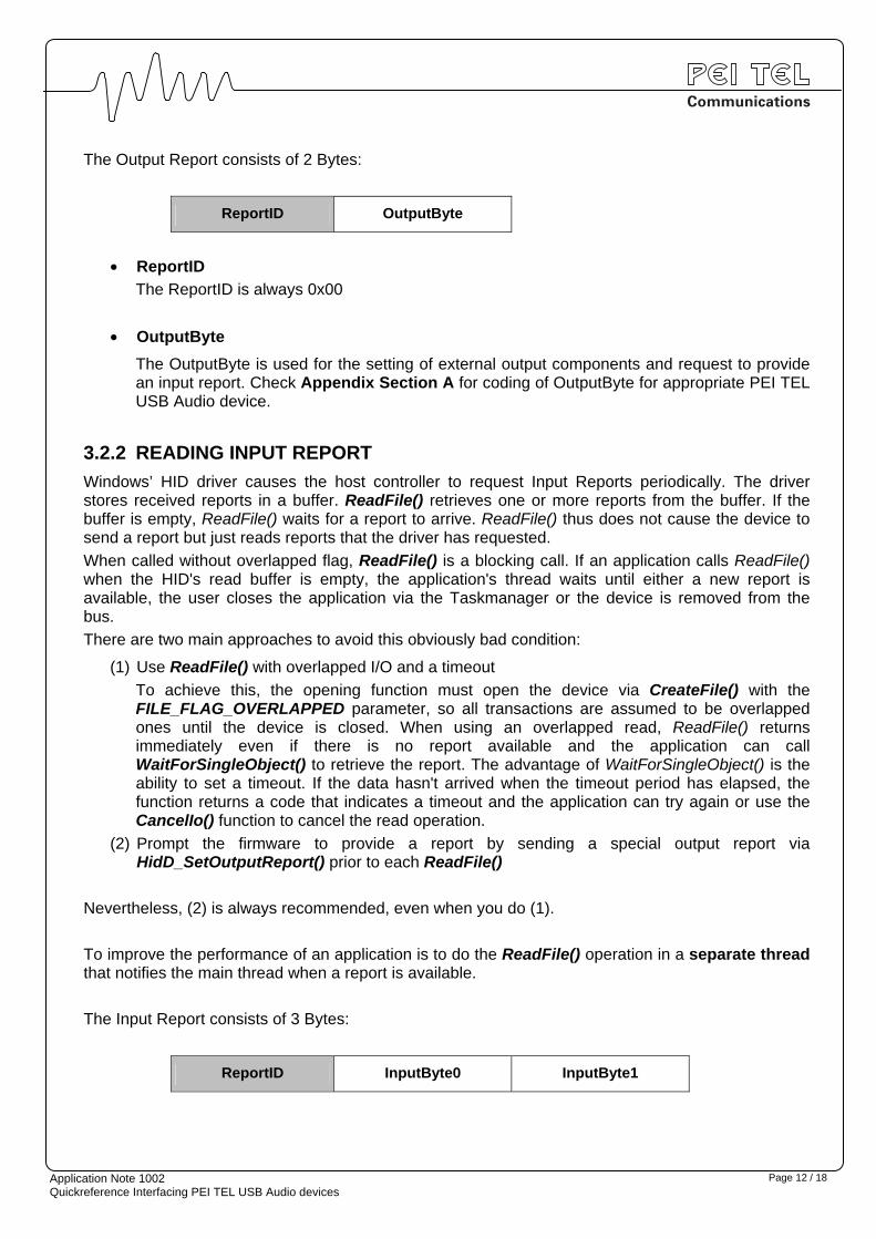
The Output Report consists of 2 Bytes:
ReportID OutputByte
• ReportID
The ReportID is always 0x00
• OutputByte
The OutputByte is used for the setting of external output components and request to provide an input report. Check Appendix Section A for coding of OutputByte for appropriate PEI TEL USB Audio device.
3.2.2 READING INPUT REPORT
Windows’ HID driver causes the host controller to request Input Reports periodically. The driver stores received reports in a buffer. ReadFile() retrieves one or more reports from the buffer. If the buffer is empty, ReadFile() waits for a report to arrive. ReadFile() thus does not cause the device to send a report but just reads reports that the driver has requested.
When called without overlapped flag, ReadFile() is a blocking call. If an application calls ReadFile() when the HID's read buffer is empty, the application's thread waits until either a new report is available, the user closes the application via the Taskmanager or the device is removed from the bus.
There are two main approaches to avoid this obviously bad condition:
(1) Use ReadFile() with overlapped I/O and a timeout
To achieve this, the opening function must open the device via CreateFile() with the FILE_FLAG_OVERLAPPED parameter, so all transactions are assumed to be overlapped ones until the device is closed. When using an overlapped read, ReadFile() returns immediately even if there is no report available and the application can call WaitForSingleObject() to retrieve the report. The advantage of WaitForSingleObject() is the ability to set a timeout. If the data hasn't arrived when the timeout period has elapsed, the function returns a code that indicates a timeout and the application can try again or use the CancelIo() function to cancel the read operation.
(2) Prompt the firmware to provide a report by sending a special output report via HidD_SetOutputReport() prior to each ReadFile()
Nevertheless, (2) is always recommended, even when you do (1).
To improve the performance of an application is to do the ReadFile() operation in a separate thread that notifies the main thread when a report is available.
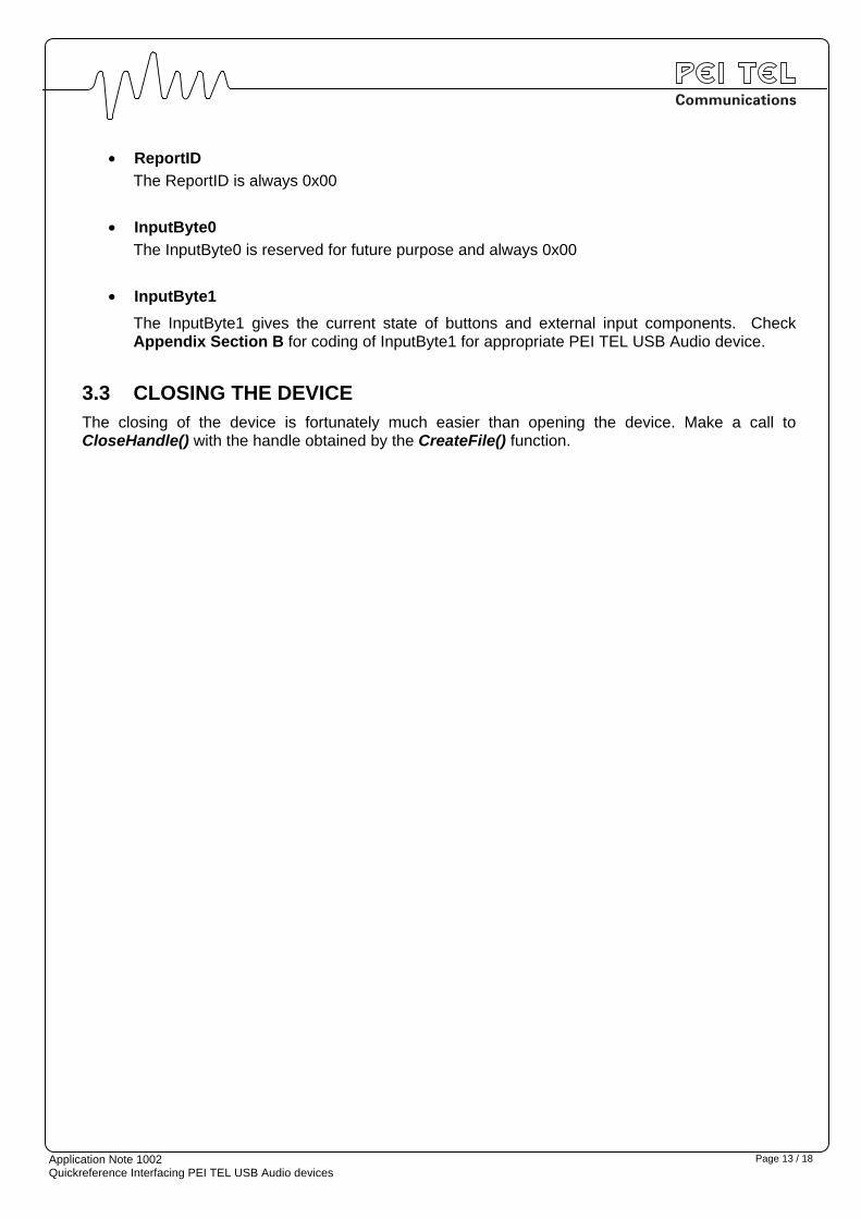
The Input Report consists of 3 Bytes:
ReportID InputByte0 InputByte1
Application Note 1002 Quickreference Interfacing PEI TEL USB Audio devices
Page 13 / 18
• ReportID
The ReportID is always 0x00
• InputByte0
The InputByte0 is reserved for future purpose and always 0x00
• InputByte1
The InputByte1 gives the current state of buttons and external input components. Check Appendix Section B for coding of InputByte1 for appropriate PEI TEL USB Audio device.
3.3 CLOSING THE DEVICE The closing of the device is fortunately much easier than opening the device. Make a call to CloseHandle() with the handle obtained by the CreateFile() function.

Application Note 1002 Quickreference Interfacing PEI TEL USB Audio devices
Page 14 / 18
APPENDIX A-1: OUTPUTBYTE PS12
Type of Product: 1xx
Layout: The OutputByte for the PS12 USB is coded as shown below:
7 6 5 4 3 2 1 0 Bit
PS12 RIR MUTE DMIC - - - CLED - OutputByte
Default - 0 1 - - - 0 -
• "-": Reserved These Bits are reserved and should be set to "0"
• CLED: Center LED Sets or unsets the center LED, if equipped
0 Turn off center LED 1 Turn on center LED
• MUTE, DMIC: Mute and Microphone select Selects the microphone and mute state according to the following table:
MUTE DMIC Active Microphone Mute State
0 0 ignored (no change) ignored (no change)
0 1 Desktop Microphone No Mute
1 X Don't care Mute
X = don't care
Remark: The microphone can also be muted manually via the Mute Checkbox in the Recording Panel of the Windows ® Mixer Panel.
• RIR: Request Input Report Prompt the device to provide Input Report for following ReadFile() operation.
0 Input Report is not requested => normal Set operation
1 Device is requested to provide Input Report
Range: 0x00 – 0x7F Set operation only
0x80 Prompt to provide Input Report only (no change of outputs)
0x81 – 0xFF Set operation and prompt to provide Input Report

Application Note 1002 Quickreference Interfacing PEI TEL USB Audio devices
Page 15 / 18
APPENDIX A-2: OUTPUTBYTE PS20
Type of Product: 2xx
Layout: The OutputByte for the PS20 USB is coded as shown below:
7 6 5 4 3 2 1 0 Bit
PS12 RIR MUTE DMIC HMIC SPK RLED CLED LLED OutputByte
Default - 0 1 0 1 0 0 0
• LLED: Left LED Sets or unsets the left LED, if equipped
0 Turn off left LED 1 Turn on left LED
• CLED: Center LED Sets or unsets the center LED, if equipped
0 Turn off center LED 1 Turn on center LED
• RLED: Right LED Sets or unsets the right LED, if equipped
0 Turn off right LED 1 Turn on right LED
• SPK: Speaker Activates or deactivates the speaker in the device
0 Deactivate speaker 1 Activate speaker
Remark: The speaker can also be muted manually via the Mute Checkbox in the Playback Panel of the Windows ® Mixer Panel.
• MUTE, DMIC, HMIC: Mute and Microphone select Selects the active microphone and mute state according to the following table:
MUTE DMIC HMIC Active Microphone Mute State
0 0 0 ignored (no change) ignored (no change)
0 0 1 Headset Microphone No Mute
0 1 0 Desktop Microphone No Mute
0 1 1 ignored (no change) ignored (no change)
1 X X Don't care Mute
X = don't care

Application Note 1002 Quickreference Interfacing PEI TEL USB Audio devices
Page 16 / 18
Remark: The microphone can also be muted manually via the Mute Checkbox in the Recording Panel of the Windows ® Mixer Panel.
• RIR: Request Input Report Prompt the device to provide Input Report for following ReadFile() operation.
0 Input Report is not requested => normal Set operation
1 Device is requested to provide Input Report
Range: 0x00 – 0x7F Set operation only
0x80 Prompt to provide Input Report only (no change of outputs)
0x81 – 0xFF Set operation and prompt to provide Input Report
Remark(s): When a headset is connected, the device automatically selects the Headset Microphone as the active microphone and the microphone will be unmuted. The application does not have to do this, but should keep it in mind upon Headset detection. The application may select the Desktop Microphone on demand afterwards.
When the Headset is disconnected, the device automatically selects the Desktop Microphone, the microphone is unmuted and the Speaker is activated, even if it was deactivated before. The application does not have to do this, but should keep it in mind upon Headset removal detection. The reason is that many people just remove their Headset at the end of the shift and leave. The successor then might not know that the microphone is muted and the speaker is deactivated. The speaker of the Headset can not be deactivated.

Application Note 1002 Quickreference Interfacing PEI TEL USB Audio devices
Page 17 / 18
APPENDIX B-1: INPUTBYTE1 PS12
Type of Product: 1xx
Layout: The InputByte1 for the PS12 USB is coded as shown below:
7 6 5 4 3 2 1 0 Bit
PS12 - - - BCNT PWR - - - InputByte1
• "-": Reserved These Bits are reserved and read as "1"
• PWR: Power Determines source of power supply.
0 Powered from USB 1 Powered from external power supply, if equipped
• BCNT: Center Button Determines current state of the center button
0 Center button pressed (active) 1 Center button released (inactive)

Application Note 1002 Quickreference Interfacing PEI TEL USB Audio devices
Page 18 / 18
APPENDIX B-2: INPUTBYTE1 PS20
Type of Product: 2xx
Layout: The InputByte1 for the PS20 USB is coded as shown below:
7 6 5 4 3 2 1 0 Bit
PS20 BRG BEXT BLFT BCNT PWR EHS - - InputByte1
• "-": Reserved These Bits are reserved and read as "1"
• EHS: External Headset Determines whether there is an external headset connected or not.
0 External headset connected 1 No external headset connected
• PWR: Power Determines source of power supply. Devices with a speaker may require an external power supply since the audio amplifier might require under certain conditions more power than the USB port can provide.
0 Powered from USB 1 Powered from external power supply
• BCNT: Center Button Determines current state of the center button
0 Center button pressed (active) 1 Center button released (inactive)
• BLFT: Left Button Determines current state of the left button
0 Left button pressed (active) 1 Left button released (inactive)
• BEXT: External Button Determines current state of the external button (usually external PTT switch)
0 External button pressed (active) 1 External button released (inactive)
• BRG: Right Button Determines current state of the right button
0 Right button pressed (active) 1 Right button released (inactive)
E N D O F D O C U M E N T