an194: design guidelines for using dsp blocks in the leonardo spectrum software
TRANSCRIPT

Altera Corporation 1
April 2002, ver. 1.0 Application Note 194
AN-194-1.0
Introduction AlteraR StratixTM devices have dedicated digital signal processing (DSP) blocks optimized for DSP applications. DSP blocks are ideal for implementing DSP applications requiring high data throughput, such as finite impulse response (FIR) filters, complex FIR filters, infinite impulse response (IIR) filters, fast Fourier transform (FFT) functions, direct cosine transform (DCT) functions, and correlators.
This document provides design guidelines for using the Stratix DSP blocks in the LeonardoSpectrumR version 2002a software.
DSP Blocks in Stratix Devices
The DSP blocks in Stratix devices consists of multipliers, adders, subtractors, accumulators, and summation units. Optional pipeline, input, and output registers are also available.
You can configure a DSP block in one of four operation modes as shown in Table 1.
f For details on DSP block features and operation modes, refer to AN 214: Using DSP Blocks in Stratix Devices.
Table 1. Operation Modes for DSP Block
DSP Block ModeNumber & Size of Multipliers per DSP Block
9 × 9-bit 18 × 18-bit 36 × 36-bit
Simple multiplier 8 multipliers with 8 product outputs
4 multipliers with 4 product outputs
1 multiplier with 1 product output
Multiply-accumulator 2 multiply and accumulate (34 bit)
2 multiply and accumulate (52 bit)
N/A
Two-multipliers adder 4 sums of 2 multiplier products each
2 sums of 2 multiplier products each
N/A
Four-multipliers adder 2 sums of 4 multiplier products each
1 sum of 4 multiplier products each
N/A
Design Guidelines forUsing DSP Blocks
in the LeonardoSpectrum Software
an194.fm Page 1 Friday, April 26, 2002 11:13 AM
2 Altera Corporation
AN 194: Design Guidelines for Using DSP Blocks in the LeonardoSpectrum Software
DSP Block Megafunctions in the Quartus II Software
The following Altera megafunctions are used with DSP block modes:
■ lpm_mult■ altmult_accum■ altmult_add
You can instantiate these megafunctions in the design or have a third-party synthesis tool, such as the LeonardoSpectrum software, infer the appropriate megafunction by recognizing a multiplier, multiply accumulator (MAC), or multiply-adder in the design. The Altera QuartusR II software maps the functions to the DSP blocks in the device during place-and-route.
f For details on these megafunctions, refer to AN 214: Using DSP Blocks in Stratix Devices.
Inferring DSP Blocks
Based on the VHDL or Verilog coding style, the LeonardoSpectrum software can infer the correct megafunctions.
Simple Multipliers
The lpm_mult megafunction implements the DSP block in the simple multiplier mode. In this mode:
■ The DSP block includes registers for the input and output stages and an intermediate pipeline stage.
■ Signed and unsigned arithmetic are supported.
Table 2 shows the LPM_PIPELINE values corresponding to the latency and registers used.
an194.fm Page 2 Friday, April 26, 2002 11:13 AM

Altera Corporation 3
AN 194: Design Guidelines for Using DSP Blocks in the LeonardoSpectrum Software
1 The latency or number of pipeline stages in the design is passed to the Quartus II software using the LPM_PIPELINE parameter. The Leonardo-Spectrum software automatically sets this parameter based on the design.
Note to Table 2:(1) A latency larger than 3 requires the use of logic element (LE) registers external to
the DSP block.
1 The lpm_mult megafunction does not support using the input registers as shift registers. Hence, the LeonardoSpectrum software does not infer lpm_mult megafunctions with input registers being used as shift registers.
Figures 1 and 2 show sample Verilog and VHDL code, respectively, for inferring the lpm_mult megafunction in the LeonardoSpectrum software. These code samples do not use the input, output, or pipeline registers.
f Associated with this application note are sample code text files (leonardospectrum_verilog.txt and leonardospectrum_vhdl.txt) in the Literature section of the Altera web site available at http://www.altera.com. The sample code in these text files use the input, output, and pipeline registers along with the simple multiplier.
Figure 1. Verilog HDL Code for Inferring lpm_mult (Unsigned 8 ×8 Multiplier)module lpm_mult_8_unsigned (out, a, b);
//Port Declarationsoutput [15:0] out;input [7:0] a;input [7:0] b;
assign out = a * b;
endmodule
Table 2. lpm_mult Megafunction Latency Values
LPM_PIPELINEValue
DSP Block Registers UsedLatency (1)
Input Pipeline Output
0 - - - 0
1 v - - 1
2 v v - 2
3 v v v 3
an194.fm Page 3 Friday, April 26, 2002 11:13 AM
4 Altera Corporation
AN 194: Design Guidelines for Using DSP Blocks in the LeonardoSpectrum Software
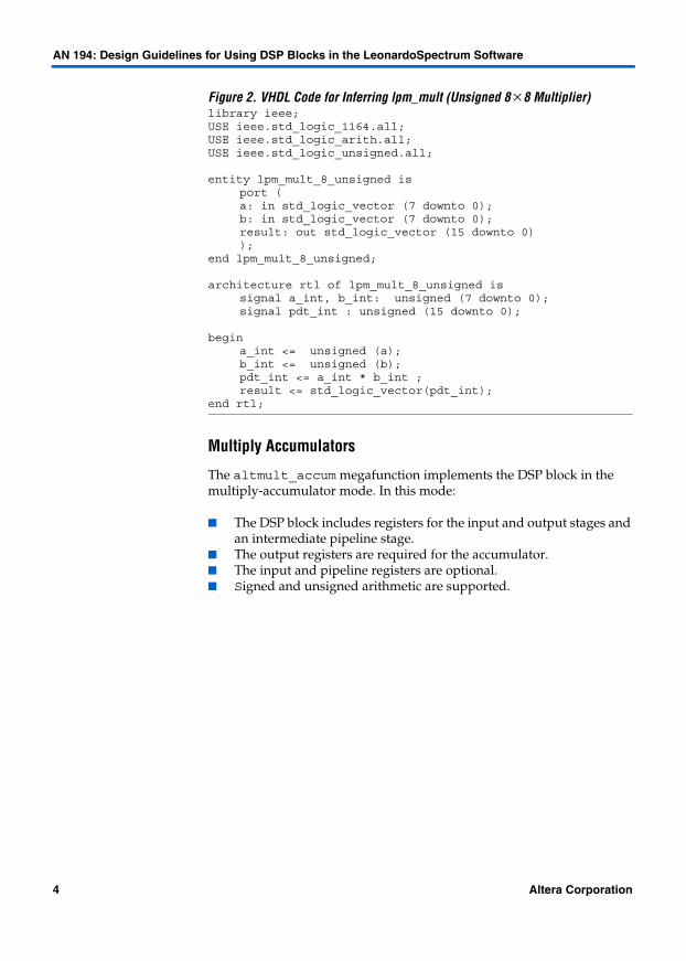
Figure 2. VHDL Code for Inferring lpm_mult (Unsigned 8 ×8 Multiplier)library ieee;USE ieee.std_logic_1164.all;USE ieee.std_logic_arith.all;USE ieee.std_logic_unsigned.all;
entity lpm_mult_8_unsigned isport (a: in std_logic_vector (7 downto 0);b: in std_logic_vector (7 downto 0);result: out std_logic_vector (15 downto 0));
end lpm_mult_8_unsigned;
architecture rtl of lpm_mult_8_unsigned issignal a_int, b_int: unsigned (7 downto 0);signal pdt_int : unsigned (15 downto 0);
begina_int <= unsigned (a);b_int <= unsigned (b);pdt_int <= a_int * b_int ;result <= std_logic_vector(pdt_int);
end rtl;
Multiply Accumulators
The altmult_accum megafunction implements the DSP block in the multiply-accumulator mode. In this mode:
■ The DSP block includes registers for the input and output stages and an intermediate pipeline stage.
■ The output registers are required for the accumulator.■ The input and pipeline registers are optional.■ Signed and unsigned arithmetic are supported.
an194.fm Page 4 Friday, April 26, 2002 11:13 AM
Altera Corporation 5
AN 194: Design Guidelines for Using DSP Blocks in the LeonardoSpectrum Software
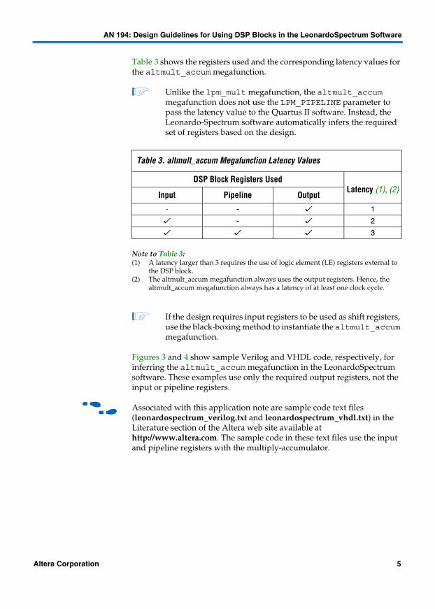
Table 3 shows the registers used and the corresponding latency values for the altmult_accum megafunction.
1 Unlike the lpm_mult megafunction, the altmult_accum megafunction does not use the LPM_PIPELINE parameter to pass the latency value to the Quartus II software. Instead, the Leonardo-Spectrum software automatically infers the required set of registers based on the design.
Note to Table 3:(1) A latency larger than 3 requires the use of logic element (LE) registers external to
the DSP block.(2) The altmult_accum megafunction always uses the output registers. Hence, the
altmult_accum megafunction always has a latency of at least one clock cycle.
1 If the design requires input registers to be used as shift registers, use the black-boxing method to instantiate the altmult_accum megafunction.
Figures 3 and 4 show sample Verilog and VHDL code, respectively, for inferring the altmult_accum megafunction in the LeonardoSpectrum software. These examples use only the required output registers, not the input or pipeline registers.
f Associated with this application note are sample code text files (leonardospectrum_verilog.txt and leonardospectrum_vhdl.txt) in the Literature section of the Altera web site available at http://www.altera.com. The sample code in these text files use the input and pipeline registers with the multiply-accumulator.
Table 3. altmult_accum Megafunction Latency Values
DSP Block Registers UsedLatency (1), (2)
Input Pipeline Output- - v 1
v - v 2
v v v 3
an194.fm Page 5 Friday, April 26, 2002 11:13 AM

6 Altera Corporation
AN 194: Design Guidelines for Using DSP Blocks in the LeonardoSpectrum Software
Figure 3. Verilog HDL Code for Inferring altmult_accum (Unsigned 8 × 8 Multiplier & 32-bit Accumulator)module altmult_acc_8_outreg_unsigned (dataout, dataa, datab,
clk, aclr, clken);
//Port Declarationsinput [7:0] dataa;input [7:0] datab;input clk;input aclr;input clken;
output [31:0] dataout;
//Register Declarationsreg [31:0] dataout;
//Wire Declarationswire [15:0] multa;wire [31:0] adder_out;
assign multa = dataa * datab;assign adder_out = multa + dataout;
always @(posedge clk or posedge aclr)begin
if(aclr)begin
dataout <= 0;end
else if(clken)begin
dataout <= adder_out;end
end
endmodule
an194.fm Page 6 Friday, April 26, 2002 11:13 AM

Altera Corporation 7
AN 194: Design Guidelines for Using DSP Blocks in the LeonardoSpectrum Software
Figure 4. VHDL Code for Inferring altmult_accum (Unsigned 8 × 8 Multiplier & 16-bit Accumulator)library ieee;USE ieee.std_logic_1164.all;
USE ieee.std_logic_arith.all;USE ieee.std_logic_unsigned.all;
entity usigaltmult_accum1 isgeneric (size : integer := 4);port (
a: in std_logic_vector (7 downto 0);b: in std_logic_vector (7 downto 0);clk : in std_logic;accum_out: inout std_logic_vector (15 downto 0));
end usigaltmult_accum1;
architecture synthesis of usigaltmult_accum1 issignal a_int, b_int : unsigned (7 downto 0);signal pdt_int : unsigned (15 downto 0);signal adder_out : unsigned (15 downto 0);
begina_int <= unsigned (a);b_int <= unsigned (b);pdt_int <= a_int * b_int;adder_out <= pdt_int + unsigned(accum_out);process (clk) begin
if (clk'event and clk = '1') thenaccum_out <= std_logic_vector (adder_out);
end if;end process;
end synthesis ;
Multiplier Adders
The LeonardoSpectrum software can infer multiplier adders and map them to either the two-multiplier adder mode or the four-multiplier adder mode of the DSP blocks. The LeonardoSpectrum software maps the HDL code to the correct altmult_add function.
In these modes:
■ The DSP block includes registers for the input and output stages and an intermediate pipeline stage.
■ Signed and unsigned arithmetic are supported.
an194.fm Page 7 Friday, April 26, 2002 11:13 AM

8 Altera Corporation
AN 194: Design Guidelines for Using DSP Blocks in the LeonardoSpectrum Software
Table 4 shows the registers used and the corresponding latency values for the altmult_add megafunction.
1 Unlike the lpm_mult megafunction, the altmult_add megafunction does not use the LPM_PIPELINE parameter to pass the latency value to the Quartus II software. Instead, the LeonardoSpectrum software infers the required set of registers based on the design.
Note to Table 4:(1) A latency larger than 3 requires the use of logic element (LE) registers external to
the DSP block.
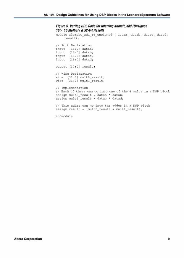
The altmult_add megafunction allows you to choose any of the register sets based on the HDL coding style. Figures 5 and 6 show sample Verilog and VHDL code, respectively, for inferring altmult_add. These samples do not use any of the register sets.
f Associated with this application note are sample code text files (leonardospectrum_verilog.txt and leonardospectrum_vhdl.txt) in the Literature section of the Altera web site available at http://www.altera.com. The sample code in these text files use the input and pipeline registers with the altmult_add megafunction.
Table 4. altmult_add Megafunction Latency Values
DSP Block Registers Used
Latency (1)Input Pipeline Output
- - - 0
v - - 1
v v - 2
v v v 3
an194.fm Page 8 Friday, April 26, 2002 11:13 AM
Altera Corporation 9
AN 194: Design Guidelines for Using DSP Blocks in the LeonardoSpectrum Software
Figure 5. Verilog HDL Code for Inferring altmult_add (Unsigned 16 × 16 Multiply & 32-bit Result)module altmult_add_16_unsigned ( dataa, datab, datac, datad,
result);
// Port Declarationinput [15:0] dataa;input [15:0] datab;input [15:0] datac;input [15:0] datad;
output [32:0] result;
// Wire Declarationwire [31:0] mult0_result;wire [31:0] mult1_result;
// Implementation// Each of these can go into one of the 4 mults in a DSP blockassign mult0_result = dataa * datab;assign mult1_result = datac * datad;
// This adder can go into the adder in a DSP blockassign result = (mult0_result + mult1_result);
endmodule
an194.fm Page 9 Friday, April 26, 2002 11:13 AM

10 Altera Corporation
AN 194: Design Guidelines for Using DSP Blocks in the LeonardoSpectrum Software
Figure 6. VHDL Code for Inferring altmult_add (Unsigned 8 × 8 Multiply & 16-bit Result)library ieee;USE ieee.std_logic_1164.all;USE ieee.std_logic_arith.all;USE ieee.std_logic_unsigned.all;
entity unsignedmult_add is port ( a: in std_logic_vector (7 downto 0); b: in std_logic_vector (7 downto 0); c: in std_logic_vector (7 downto 0); d: in std_logic_vector (7 downto 0); result: out std_logic_vector (15 downto 0) );end unsignedmult_add;
architecture rtl of unsignedmult_add is signal a_int, b_int, c_int, d_int : unsigned (7 downto 0); signal pdt_int, pdt2_int : unsigned (15 downto 0); signal result_int: unsigned (15 downto 0);begin a_int <= unsigned (a); b_int <= unsigned (b); c_int <= unsigned (c); d_int <= unsigned (d); pdt_int <= a_int * b_int; pdt2_int <= c_int * d_int; result_int <= pdt_int + pdt2_int; result <= std_logic_vector(result_int);end rtl ;
an194.fm Page 10 Friday, April 26, 2002 11:13 AM

Altera Corporation 11
AN 194: Design Guidelines for Using DSP Blocks in the LeonardoSpectrum Software
Controlling DSP Block Inferencing
Multipliers, accumulators, and adders can be implemented in DSP blocks or in logic elements in Stratix devices. The user can control this implementation through attribute settings in the LeonardoSpectrum software.
As shown in Table 5 attribute settings in the LeonardoSpectrum software control the implementation of the multipliers in the DSP blocks or LEs at the signal, block (or module), and project level.
Notes to Table 5:(1) For Stratix devices, the extract_mac attribute is set to TRUE by default for the entire project.(2) For Stratix devices, the extract_mac attribute is set to TRUE by default for all modules.(3) The extract_mac attribute takes precedence over the dedicated_mult attribute.
Global Attribute
You can set the global attribute extract_mac to control the implementation of multipliers in DSP blocks for the entire project. You can set this attribute using the script interface. The script command is:
set extract_mac <value>
Table 5. Attribute Settings for DSP Blocks in the LeonardoSpectrum Software Note (3)
Level Attribute Name Value Description
Global extract_mac (1) TRUE All multipliers in the project mapped to DSP blocks
FALSE All multipliers in the project mapped to LEs
Module extract_mac (2) TRUE Multipliers inside the specified module mapped to DSP blocks
FALSE Multipliers inside the specified module mapped to LEs
Signal dedicated_mult ON LPM inferred and multipliers implemented in DSP block
OFF LPM inferred, but multipliers implemented in LEs by the Quartus II software
LCELL LPM not inferred and multipliers implemented in LEs by the LeonardoSpectrum software
AUTO LPM inferred, but the Quartus II software automatically maps the multipliers to either LEs or DSP blocks based on the Quartus II software place-and-route
an194.fm Page 11 Friday, April 26, 2002 11:13 AM

12 Altera Corporation
AN 194: Design Guidelines for Using DSP Blocks in the LeonardoSpectrum Software
Module Level Attributes
You can control the implementation of multipliers inside a module or component by setting attributes in the HDL source code. The attribute used is extract_mac. Setting this attribute for a module affects only the multipliers inside that module.
//synthesis attribute <module name> extract_mac <value>
Figures 7 and 8 show sample Verilog and VHDL code, respectively, for using this attribute.
Figure 7. Using Module Level Attributes in Verilog HDL Codemodule mult_add ( dataa, datab, datac, datad, result);//synthesis attribute mult_add extract_mac FALSE// Port Declarationinput [15:0] dataa;input [15:0] datab;input [15:0] datac;input [15:0] datad;
output [32:0] result;
// Wire Declarationwire [31:0] mult0_result;wire [31:0] mult1_result;
// Implementation// Each of these can go into one of the 4 mults in a DSP blockassign mult0_result = dataa * `signed datab; //synthesis attribute mult0_result preserve_signal TRUE assign mult1_result = datac * datad;
// This adder can go into the one-level adder in a DSP blockassign result = (mult0_result + mult1_result);
endmodule
an194.fm Page 12 Friday, April 26, 2002 11:13 AM

Altera Corporation 13
AN 194: Design Guidelines for Using DSP Blocks in the LeonardoSpectrum Software
Figure 8. Using Module Level Attributes in VHDL Codelibrary ieee ;USE ieee.std_logic_1164.all;
USE ieee.std_logic_arith.all;
entity mult_acc is generic (size : integer := 4) ; port ( a: in std_logic_vector (size-1 downto 0) ; b: in std_logic_vector (size-1 downto 0) ; clk : in std_logic; accum_out: inout std_logic_vector (2*size downto 0) ) ; attribute extract_mac : boolean; attribute extract_mac of mult_acc : entity is FALSE; end mult_acc;
architecture synthesis of mult_acc is signal a_int, b_int : signed (size-1 downto 0); signal pdt_int : signed (2*size-1 downto 0); signal adder_out : signed (2*size downto 0);begin a_int <= signed (a); b_int <= signed (b); pdt_int <= a_int * b_int; adder_out <= pdt_int + signed(accum_out); process (clk) begin if (clk'event and clk = '1') then accum_out <= std_logic_vector (adder_out); end if; end process;end synthesis ;
Signal Level Attributes
You can control the implementation of individual multipliers by using the dedicated_mult attribute as shown below:
//synthesis attribute <signal_name> dedicated_mult <value>
1 The dedicated_mult attribute only works with signals/wires; it does not work with registers.
an194.fm Page 13 Friday, April 26, 2002 11:13 AM

14 Altera Corporation
AN 194: Design Guidelines for Using DSP Blocks in the LeonardoSpectrum Software
Table 6 shows the acceptable values for the dedicated_mult attribute.
Note to Table 6:(1) Although both dedicated_mult= OFF and dedicated_mult=LCELLS result in
LE implementations, the optimized results in these two cases may differ.
1 Some signals for which dedicated_mult attribute is set may get synthesized out by the LeonardoSpectrum software due to design optimization. In such cases, if you want to force the implementation, the signal should be preserved from being synthesized out by setting the preserve_signal attribute to TRUE.
1 The extract_mac attribute must be set to “false” for the module or project level when using the dedicated_mult attribute.
Figures 9 and 10 show sample Verilog and VHDL code, respectively, using the dedicated_mult attribute.
Table 6. Values for the dedicated_mult Attribute
Value Description
ON LPM inferred and multipliers implemented in DSP block
OFF LPM inferred and multipliers synthesized, implemented in LEs, and optimized by the Quartus II software (1)
LCELL LPM not inferred and multipliers synthesized, implemented in LEs, and optimized by the LeonardoSpectrum software (1)
AUTO LPM inferred but Quartus II maps the multipliers automatically to either the DSP block or LEs based on resource availability
an194.fm Page 14 Friday, April 26, 2002 11:13 AM

Altera Corporation 15
AN 194: Design Guidelines for Using DSP Blocks in the LeonardoSpectrum Software
Figure 9. Signal Attributes for Controlling DSP Block Inference in Verilog HDL Codemodule mult (AX, AY, BX, BY, m, n, o, p);
input [7:0] AX, AY, BX, BY;output [15:0] m, n, o, p;
wire [15:0] m_i = AX * AY; // synthesis attribute m_i dedicated_mult ON
// synthesis attribute m_i preserve_signal TRUE
//Note that the preserve_signal attribute prevents signal m_i//from getting synthesized out
wire [15:0] n_i = BX * BY; // synthesis attribute n_i dedicated_mult OFF
wire [15:0] o_i = AX * BY; // synthesis attribute o_i dedicated_mult AUTO
wire [15:0] p_i = BX * AY; // synthesis attribute p_i dedicated_mult LCELL
// since n_i. o_i , p_i signals are not preserved, they may// get synthesized out based on the design
assign m = m_i;assign n = n_i;assign o = o_i;assign p = p_i;
endmodule
an194.fm Page 15 Friday, April 26, 2002 11:13 AM

16 Altera Corporation
AN 194: Design Guidelines for Using DSP Blocks in the LeonardoSpectrum Software
Figure 10. Signal Attributes for Controlling DSP Block Inference for VHDL Codelibrary ieee ;USE ieee.std_logic_1164.all;USE ieee.std_logic_arith.all;USE ieee.std_logic_unsigned.all;USE ieee.std_logic_signed.all;
ENTITY mult isPORT( AX,AY,BX,BY: IN std_logic_vector (17 DOWNTO 0);m,n,o,p: OUT std_logic_vector (35 DOWNTO 0));
attribute dedicated_mult: string;attribute preserve_signal : boolean
END mult;
ARCHITECTURE struct of mult is
signal m_i, n_i, o_i, p_i : unsigned (35 downto 0);attribute dedicated_mult of m_i:signal is "ON";attribute dedicated_mult of n_i:signal is "OFF";attribute dedicated_mult of o_i:signal is "AUTO";attribute dedicated_mult of p_i:signal is "LCELL";
begin
m_i <= unsigned (AX) * unsigned (AY); n_i <= unsigned (BX) * unsigned (BY); o_i <= unsigned (AX) * unsigned (BY); p_i <= unsigned (BX) * unsigned (AY);
m <= std_logic_vector(m_i);n <= std_logic_vector(n_i);o <= std_logic_vector(o_i);p <= std_logic_vector(p_i);end struct;
Black Boxing DSP Blocks
In addition to inferring the DSP block through HDL code, the LeonardoSpectrum software also supports black boxing of the DSP blocks. Using black-boxing techniques, you can instantiate a Quartus II software-generated DSP megafunction, such as lpm_mult, altmult_add, or altmult_accum. You can customize these megafunctions in the Quartus II software and take advantage of all the DSP block features through the MegaWizard Plug-In Manager.
f Refer to AN 230: Designing with Stratix Devices in LeonardoSpectrum for more details on black boxing DSP blocks in the LeonardoSpectrum software.
an194.fm Page 16 Friday, April 26, 2002 11:13 AM
Altera Corporation 17
AN 194: Design Guidelines for Using DSP Blocks in the LeonardoSpectrum Software
Guidelines for Using DSP Blocks
In addition to the guidelines mentioned earlier in this application note, use the following guidelines while designing with DSP blocks in the LeonardoSpectrum software:
■ The altmult_add megafunction is the most versatile megafunction because it allows maximum individual control of the input, pipeline, and output registers. Use the altmult_add megafunction instead of lpm_mult megafunction if you need more control of the registers available in the DSP blocks.
■ The altmult_add megafunction can implement the same functionality as the lpm_mult megafunction.
■ To access all the different control signals for the DSP block, such as sign A, sign B, and dynamic addnsub, use the black-boxing technique.
■ While performing signed operations, ensure that the specified data width of the output port matches the data width of the expected result. Otherwise the sign bit may be lost or data will be incorrect because the sign is not extended. For example, if the data widths of input A and B are width_a and width_b, respectively, then the maximum data width of the result can be (width_a + width_b +2) for the four-multipliers adder mode. Thus, the data width of the output port should be less than or equal to (width_a + width_b +2).
■ While using the accumulator, the data width of the output port should be equal to or greater than (width_a + width_b). The maximum width of the accumulator can be (width_a + width_b + 16). Accumulators wider than this are implemented in LEs.
■ If the design uses more multipliers than available in a particular Stratix device, you might get a no fit error in the Quartus II software. In such cases, use the attribute settings in the LeonardoSpectrum software to control the mapping of multipliers in your design to DSP blocks or LEs.
an194.fm Page 17 Friday, April 26, 2002 11:13 AM

AN 194: Design Guidelines for Using DSP Blocks in the LeonardoSpectrum Software
18 Altera Corporation
101 Innovation DriveSan Jose, CA 95134(408) 544-7000http://www.altera.comApplications Hotline:(800) 800-EPLDLiterature Services:[email protected]
Copyright © 2002 Altera Corporation. All rights reserved. Altera, The Programmable Solutions Company, thestylized Altera logo, specific device designations, and all other words and logos that are identified astrademarks and/or service marks are, unless noted otherwise, the trademarks and service marks of AlteraCorporation in the U.S. and other countries. All other product or service names are the property of theirrespective holders. LeonardoSpectrum is a trademark of Mentor Graphics Corporation. Altera products areprotected under numerous U.S. and foreign patents and pending applications, maskwork rights, andcopyrights. Altera warrants performance of its semiconductor products to current specifications in accordancewith Altera's standard warranty, but reserves the right to make changes to any productsand services at any time without notice. Altera assumes no responsibility or liability arisingout of the application or use of any information, product, or service described herein exceptas expressly agreed to in writing by Altera Corporation. Altera customers are advised toobtain the latest version of device specifications before relying on any publishedinformation and before placing orders for products or services
Sample HDL Code
Associated with this application note are sample code text files (leonardospectrum_verilog.txt and leonardospectrum_vhdl.txt) in the Literature section of the Altera web site available at http://www.altera.com. The sample code in these text files have sample Verilog and VHDL code examples that infer the DSP block in the different operation modes.
Table 7 is a list of the modes with sample code available in the text files.
Note to Table 7:(1) Latency of 0 is not supported as the output registers are required in this mode.
1 The syntax is slightly different for signed and unsigned representations in the sample code.
Conclusion This application note has shown how to use the LeonardoSpectrum software with the DSP blocks available in Stratix devices. The DSP block operation modes are ideal for implementing DSP applications.
Table 7. Sample Verilog HDL & VHDL Code in Text Files
MegafunctionUnsigned
OperationsSigned
OperationsLatency
0 1 2 3
lpm_mult (a*b) v v v v v v
altmult_add (a*b + c*d) v v v v v v
altmult_accum (a*b+x) v v - (1) v v v
an194.fm Page 18 Friday, April 26, 2002 11:13 AM