an4221 application note - st.com · march 2017 docid024055 rev 5 1/51 1 an4221 application note i2c...
TRANSCRIPT

March 2017 DocID024055 Rev 5 1/51
1
AN4221Application note
I2C protocol used in the STM32 bootloader
Introduction
This application note describes the I2C protocol used in the STM32 microcontroller bootloader, detailing each supported command.
This document applies to the STM32 products embedding bootloader versions V5.x, V6.x,V7.x, V8.x, V9.x, V10.x, V11.x and V13.x, as specified in the application note AN2606 “STM32 microcontroller system memory boot mode”, available on www.st.com. These products are listed in Table 1, and are referred to as STM32 throughout the document.
For more information about the I2C hardware resources and requirements for your device bootloader, refer to the already mentioned AN2606.
.
– STM32F030xC, STM32F04xxx, STM32F07xxx, STM32F09xxx
– STM32F303xx, STM32F318xx, STM32F328xx, STM32F334xx, STM32F358xx, STM32F378xx, STM32F398xx
– STM32F401xx, STM32F405xx, STM32F407xx, STM32F410xx, STM32F411xx, STM32F412xx, STM32F415xx, STM32F417xx, STM32F427xx, STM32F429xx, STM32F437xx, STM32F439xx, STM32F446xx, STM32F469xx, STM32F479xx
– STM32F722xx, STM32F723xx, STM32F732xx, STM32F733xx, STM32F745xx, STM32F746xx, STM32F756xx, STM32F765xx, STM32F767xx, STM32F769xx, STM32F777xx, STM32F779xx
– STM32L07xxx, STM32L08xxx
– STM32L431xx, STM32L432xx, STM32L433xx, STM32L442xx, STM32L443xx, STM32L471xx, STM32L475xx, STM32L476xx, STM32L486xx, STM32L496xx, STM32L4A6xx
Table 1. Applicable products
Type Part numbers
Microcontrollers
STM32F0 Series:
STM32F3 Series:
STM32F4 Series:
STM32F7 Series:
STM32L0 Series:
STM32L4 Series:
www.st.com

Contents AN4221
2/51 DocID024055 Rev 5
Contents
1 I2C bootloader code sequence . . . . . . . . . . . . . . . . . . . . . . . . . . . . . . . . 5
2 Bootloader command set . . . . . . . . . . . . . . . . . . . . . . . . . . . . . . . . . . . . . 6
2.1 Get command . . . . . . . . . . . . . . . . . . . . . . . . . . . . . . . . . . . . . . . . . . . . . . . 8
2.2 Get version command . . . . . . . . . . . . . . . . . . . . . . . . . . . . . . . . . . . . . . . .11
2.3 Get ID command . . . . . . . . . . . . . . . . . . . . . . . . . . . . . . . . . . . . . . . . . . . 12
2.4 Read memory command . . . . . . . . . . . . . . . . . . . . . . . . . . . . . . . . . . . . . 14
2.5 Go command . . . . . . . . . . . . . . . . . . . . . . . . . . . . . . . . . . . . . . . . . . . . . . 17
2.6 Write memory command . . . . . . . . . . . . . . . . . . . . . . . . . . . . . . . . . . . . . 20
2.7 Erase memory command . . . . . . . . . . . . . . . . . . . . . . . . . . . . . . . . . . . . . 23
2.8 Write protect command . . . . . . . . . . . . . . . . . . . . . . . . . . . . . . . . . . . . . . 26
2.9 Write unprotect command . . . . . . . . . . . . . . . . . . . . . . . . . . . . . . . . . . . . 29
2.10 Readout protect command . . . . . . . . . . . . . . . . . . . . . . . . . . . . . . . . . . . . 30
2.11 Readout unprotect command . . . . . . . . . . . . . . . . . . . . . . . . . . . . . . . . . . 32
2.12 No-Stretch Write memory command . . . . . . . . . . . . . . . . . . . . . . . . . . . . 34
2.13 No-Stretch Erase memory command . . . . . . . . . . . . . . . . . . . . . . . . . . . . 37
2.14 No-Stretch Write protect command . . . . . . . . . . . . . . . . . . . . . . . . . . . . . 40
2.15 No-Stretch Write unprotect command . . . . . . . . . . . . . . . . . . . . . . . . . . . 43
2.16 No-Stretch Readout protect command . . . . . . . . . . . . . . . . . . . . . . . . . . . 44
2.17 No-Stretch Readout unprotect command . . . . . . . . . . . . . . . . . . . . . . . . . 46
3 Bootloader protocol version evolution . . . . . . . . . . . . . . . . . . . . . . . . . 49
4 Revision history . . . . . . . . . . . . . . . . . . . . . . . . . . . . . . . . . . . . . . . . . . . 50
DocID024055 Rev 5 3/51
AN4221 List of tables
3
List of tables
Table 1. Applicable products . . . . . . . . . . . . . . . . . . . . . . . . . . . . . . . . . . . . . . . . . . . . . . . . . . . . . . . 1Table 2. I2C bootloader commands . . . . . . . . . . . . . . . . . . . . . . . . . . . . . . . . . . . . . . . . . . . . . . . . . . 6Table 3. Bootloader protocol versions . . . . . . . . . . . . . . . . . . . . . . . . . . . . . . . . . . . . . . . . . . . . . . . 49Table 4. Document revision history . . . . . . . . . . . . . . . . . . . . . . . . . . . . . . . . . . . . . . . . . . . . . . . . . 50
List of figures AN4221
4/51 DocID024055 Rev 5
List of figures
Figure 1. Bootloader for STM32 with I2C. . . . . . . . . . . . . . . . . . . . . . . . . . . . . . . . . . . . . . . . . . . . . . . 5Figure 2. Get command: host side. . . . . . . . . . . . . . . . . . . . . . . . . . . . . . . . . . . . . . . . . . . . . . . . . . . . 8Figure 3. Get command: device side . . . . . . . . . . . . . . . . . . . . . . . . . . . . . . . . . . . . . . . . . . . . . . . . . . 9Figure 4. Get version: host side . . . . . . . . . . . . . . . . . . . . . . . . . . . . . . . . . . . . . . . . . . . . . . . . . . . . . 11Figure 5. Get version: device side . . . . . . . . . . . . . . . . . . . . . . . . . . . . . . . . . . . . . . . . . . . . . . . . . . . 12Figure 6. Get ID command: host side . . . . . . . . . . . . . . . . . . . . . . . . . . . . . . . . . . . . . . . . . . . . . . . . 13Figure 7. Get ID command: device side. . . . . . . . . . . . . . . . . . . . . . . . . . . . . . . . . . . . . . . . . . . . . . . 13Figure 8. Read memory command: host side . . . . . . . . . . . . . . . . . . . . . . . . . . . . . . . . . . . . . . . . . . 15Figure 9. Read memory command: device side . . . . . . . . . . . . . . . . . . . . . . . . . . . . . . . . . . . . . . . . 16Figure 10. Go command: host side . . . . . . . . . . . . . . . . . . . . . . . . . . . . . . . . . . . . . . . . . . . . . . . . . . . 18Figure 11. Go command: device side . . . . . . . . . . . . . . . . . . . . . . . . . . . . . . . . . . . . . . . . . . . . . . . . . 19Figure 12. Write memory command: host side . . . . . . . . . . . . . . . . . . . . . . . . . . . . . . . . . . . . . . . . . . 21Figure 13. Write memory command: device side. . . . . . . . . . . . . . . . . . . . . . . . . . . . . . . . . . . . . . . . . 22Figure 14. Erase memory command: host side . . . . . . . . . . . . . . . . . . . . . . . . . . . . . . . . . . . . . . . . . . 24Figure 15. Erase memory command: device side . . . . . . . . . . . . . . . . . . . . . . . . . . . . . . . . . . . . . . . . 25Figure 16. Write protect command: host side . . . . . . . . . . . . . . . . . . . . . . . . . . . . . . . . . . . . . . . . . . . 27Figure 17. Write protect command: device side. . . . . . . . . . . . . . . . . . . . . . . . . . . . . . . . . . . . . . . . . . 28Figure 18. Write unprotect command: host side . . . . . . . . . . . . . . . . . . . . . . . . . . . . . . . . . . . . . . . . . 29Figure 19. Write unprotect command: device side. . . . . . . . . . . . . . . . . . . . . . . . . . . . . . . . . . . . . . . . 30Figure 20. Readout protect command: host side . . . . . . . . . . . . . . . . . . . . . . . . . . . . . . . . . . . . . . . . . 31Figure 21. Readout protect command: device side . . . . . . . . . . . . . . . . . . . . . . . . . . . . . . . . . . . . . . . 31Figure 22. Readout unprotect command: host side . . . . . . . . . . . . . . . . . . . . . . . . . . . . . . . . . . . . . . . 32Figure 23. Readout unprotect command: device side . . . . . . . . . . . . . . . . . . . . . . . . . . . . . . . . . . . . . 33Figure 24. No-Stretch Write memory command: host side . . . . . . . . . . . . . . . . . . . . . . . . . . . . . . . . . 35Figure 25. No-Stretch Write memory command: device side. . . . . . . . . . . . . . . . . . . . . . . . . . . . . . . . 36Figure 26. No-Stretch Erase memory command: host side . . . . . . . . . . . . . . . . . . . . . . . . . . . . . . . . . 38Figure 27. No-Stretch Erase memory command: device side . . . . . . . . . . . . . . . . . . . . . . . . . . . . . . . 39Figure 28. No-Stretch Write protect command: host side . . . . . . . . . . . . . . . . . . . . . . . . . . . . . . . . . . 41Figure 29. No-Stretch Write protect command: device side. . . . . . . . . . . . . . . . . . . . . . . . . . . . . . . . . 42Figure 30. No-Stretch Write unprotect command: host side . . . . . . . . . . . . . . . . . . . . . . . . . . . . . . . . 43Figure 31. No-Stretch Write unprotect command: device side. . . . . . . . . . . . . . . . . . . . . . . . . . . . . . . 44Figure 32. NoStretch Readout protect command: host side . . . . . . . . . . . . . . . . . . . . . . . . . . . . . . . . 45Figure 33. No-Stretch Readout protect command: device side . . . . . . . . . . . . . . . . . . . . . . . . . . . . . . 46Figure 34. No-Stretch Readout unprotect command: host side. . . . . . . . . . . . . . . . . . . . . . . . . . . . . . 47Figure 35. No-Stretch Readout unprotect command: device side . . . . . . . . . . . . . . . . . . . . . . . . . . . . 48

DocID024055 Rev 5 5/51
AN4221 I2C bootloader code sequence
50
1 I2C bootloader code sequence
Figure 1. Bootloader for STM32 with I2C
Note: The I2C slave address for each product's bootloader is specified in the AN2606.
Once the system memory boot mode has been entered, and the STM32 microcontroller has been configured (for more details, refer to your STM32 system memory boot mode application note), the bootloader code begins to scan the I2C_SDA line pin, waiting to detect its own address on the bus. Once detected, the I2C bootloader firmware begins receiving host commands.

Bootloader command set AN4221
6/51 DocID024055 Rev 5
2 Bootloader command set
"No Stretch" commands are supported starting from V1.1 protocol version and allow a better management of commands when the Host has to wait a significant time before operation is accomplished by Bootloader.
It is highly recommended to use the "No Stretch" commands whenever possible instead of equivalent regular commands.
The supported commands are listed in Table 2.
Table 2. I2C bootloader commands
Commands(1) Command code Command description
Get(2) 0x00Gets the version and the allowed commands supported by the current version of the bootloader
Get Version(2) 0x01 Gets the bootloader version
Get ID(2) 0x02 Gets the chip ID
Read Memory 0x11Reads up to 256 bytes of memory, starting from an address specified by the application
Go(3) 0x21Jumps to user application code located in the internal Flash memory
Write Memory(3) 0x31Writes up to 256 bytes to the memory, starting from an address specified by the application
No-Stretch Write Memory(3)(4) 0x32Writes up to 256 bytes to the memory, starting from an address specified by the application and returns busy state while operation is ongoing
Erase 0x44Erases from one to all Flash memory pages or sectors using two-byte addressing mode
No-Stretch Erase(3)(4) 0x45Erases from one to all Flash memory pages or sectors using two-byte addressing mode and returns busy state while operation is ongoing
Write Protect 0x63 Enables write protection for some sectors
No-Stretch Write Protect(4) 0x64Enables write protection for some sectors and returns busy state while operation is ongoing
Write Unprotect 0x73 Disables write protection for all Flash memory sectors
No-Stretch Write Unprotect(4) 0x74Disables write protection for all Flash memory sectors and returns busy state while operation is ongoing
Readout Protect 0x82 Enables read protection
No-Stretch Readout Protect(4) 0x83Enables read protection and returns busy state while operation is ongoing
Readout Unprotect(2) 0x92 Disables read protection
No-Stretch Readout Unprotect(2)(4) 0x93Disables read protection and returns busy state while operation is ongoing
1. If a denied command is received, or if an error occurs during the command execution, the bootloader sends a NACK byte and goes back to command checking.
DocID024055 Rev 5 7/51
AN4221 Bootloader command set
50
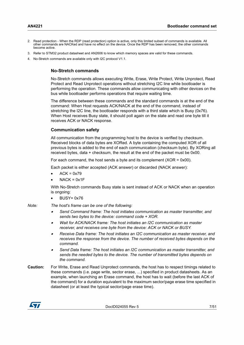
No-Stretch commands
No-Stretch commands allows executing Write, Erase, Write Protect, Write Unprotect, Read Protect and Read Unprotect operations without stretching I2C line while bootloader is performing the operation. These commands allow communicating with other devices on the bus while bootloader performs operations that require waiting time.
The difference between these commands and the standard commands is at the end of the command: When Host requests ACK/NACK at the end of the command, instead of stretching the I2C line, the bootloader responds with a third state which is Busy (0x76). When Host receives Busy state, it should poll again on the state and read one byte till it receives ACK or NACK response.
Communication safety
All communication from the programming host to the device is verified by checksum. Received blocks of data bytes are XORed. A byte containing the computed XOR of all previous bytes is added to the end of each communication (checksum byte). By XORing all received bytes, data + checksum, the result at the end of the packet must be 0x00.
For each command, the host sends a byte and its complement (XOR = 0x00).
Each packet is either accepted (ACK answer) or discarded (NACK answer):
• ACK = 0x79
• NACK = 0x1F
With No-Stretch commands Busy state is sent instead of ACK or NACK when an operation is ongoing:
• BUSY= 0x76
Note: The host's frame can be one of the following:
• Send Command frame: The host initiates communication as master transmitter, and sends two bytes to the device: command code + XOR.
• Wait for ACK/NACK frame: The host initiates an I2C communication as master receiver, and receives one byte from the device: ACK or NACK or BUSY.
• Receive Data frame: The host initiates an I2C communication as master receiver, and receives the response from the device. The number of received bytes depends on the command.
• Send Data frame: The host initiates an I2C communication as master transmitter, and sends the needed bytes to the device. The number of transmitted bytes depends on the command.
Caution: For Write, Erase and Read Unprotect commands, the host has to respect timings related to these commands (i.e. page write, sector erase, ...) specified in product datasheets. As an example, when launching an Erase command, the host has to wait (before the last ACK of the command) for a duration equivalent to the maximum sector/page erase time specified in datasheet (or at least the typical sector/page erase time).
2. Read protection - When the RDP (read protection) option is active, only this limited subset of commands is available. All other commands are NACKed and have no effect on the device. Once the RDP has been removed, the other commands become active.
3. Refer to STM32 product datasheet and AN2606 to know which memory spaces are valid for these commands.
4. No-Stretch commands are available only with I2C protocol V1.1.

Bootloader command set AN4221
8/51 DocID024055 Rev 5
Caution: For I2C communication, a timeout mechanism is implemented which must be respected for Bootloader commands to be executed correctly. This timeout is implemented between two I2C frames in the same command. For example, for a Write memory command, a timeout is inserted between the command-sending frame and address memory-sending frame. Also, the same timeout period is inserted between two successive instances of data reception or transmission in the same I2C frame. If the timeout period has elapsed, a system reset is generated to avoid a Bootloader crash. Refer to AN2606, section “I2C connection timing” to get the I2C timeout value of each STM32 product.
2.1 Get command
The Get command allows you to get the version of the bootloader and the supported commands. When the bootloader receives the Get command, it transmits the bootloader version and the supported command codes to the host, as described in Figure 2.
Figure 2. Get command: host side

DocID024055 Rev 5 9/51
AN4221 Bootloader command set
50
Figure 3. Get command: device side

Bootloader command set AN4221
10/51 DocID024055 Rev 5
The STM32 sends the bytes as follows:
• For I2C protocol V1.0:
– Byte 1: ACK
– Byte 2: N = 11 = the number of bytes to follow - 1 except current and ACKs.
– Byte 3: Bootloader version 0x10 = Version 1.0
– Byte 4: 0x00 - Get command
– Byte 5: 0x01 - Get Version
– Byte 6: 0x02 - Get ID
– Byte 7: 0x11 - Read Memory command
– Byte 8: 0x21 - Go command
– Byte 9: 0x31 - Write Memory command
– Byte 10: 0x44 - Erase command
– Byte 11: 0x63 - Write Protect command
– Byte 12: 0x73 - Write Unprotect command
– Byte 13: 0x82 - Readout Protect command
– Byte 14: 0x92 - Readout Unprotect command
– Byte 15: ACK
• For I2C protocol V1.1:
– Byte 1: ACK
– Byte 2: N = 17 = the number of bytes to follow - 1 except current and ACKs.
– Byte 3: Bootloader version 0x11 = Version 1.1
– Byte 4: 0x00 - Get command
– Byte 5: 0x01 - Get Version
– Byte 6: 0x02 - Get ID
– Byte 7: 0x11 - Read Memory command
– Byte 8: 0x21 - Go command
– Byte 9: 0x31 - Write Memory command
– Byte 10: 0x44 - Erase command
– Byte 11: 0x63 - Write Protect command
– Byte 12: 0x73 - Write Unprotect command
– Byte 13: 0x82 - Readout Protect command
– Byte 14: 0x92 - Readout Unprotect command
– Byte 15: 0x32 - No-Stretch Write Memory command
– Byte 16: 0x45 - No-Stretch Erase command
– Byte 17: 0x64 - No-Stretch Write Protect command
– Byte 18: 0x74 - No-Stretch Write Unprotect command
– Byte 19: 0x83 - No-Stretch Readout Protect command
– Byte 20: 0x93 - No-Stretch Readout Unprotect command
– Byte 21: ACK
DocID024055 Rev 5 11/51
AN4221 Bootloader command set
50
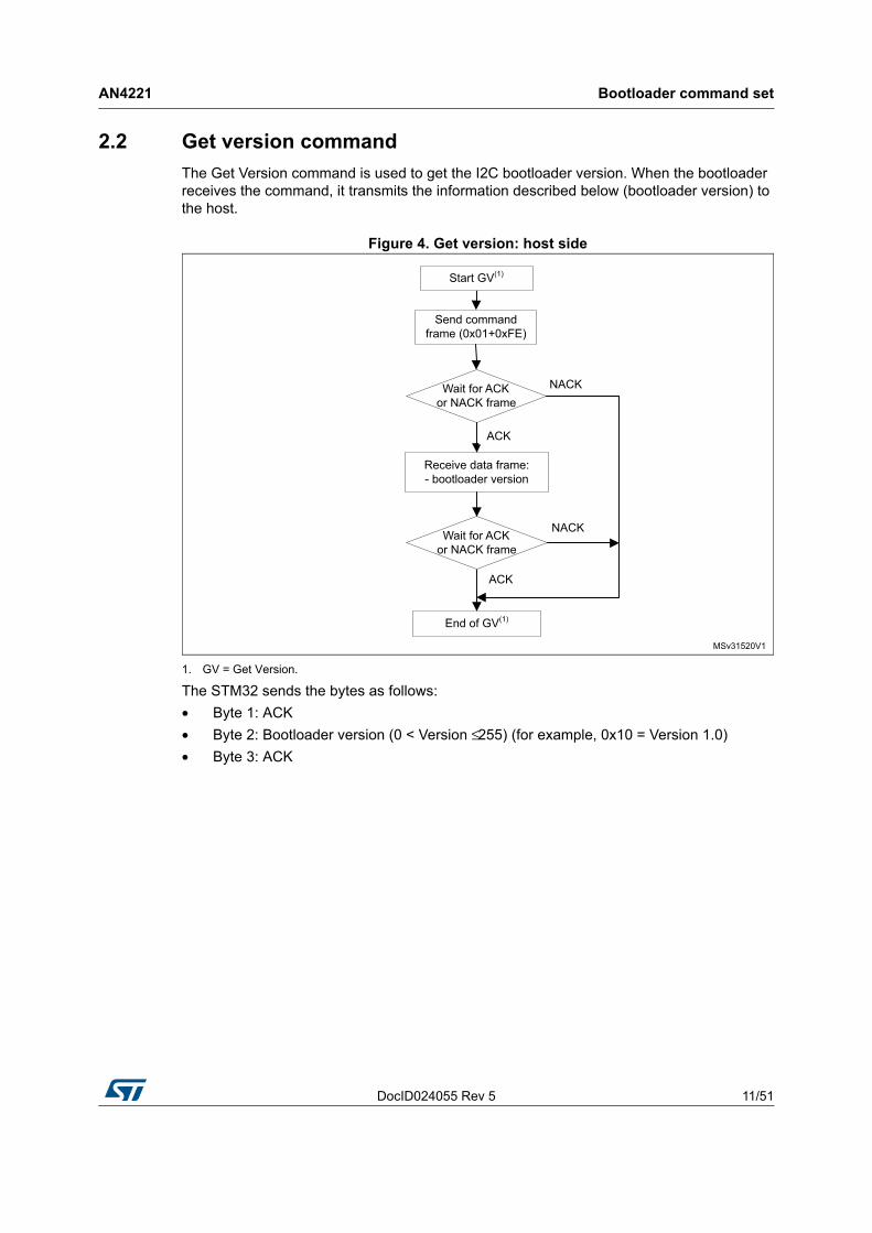
2.2 Get version command
The Get Version command is used to get the I2C bootloader version. When the bootloader receives the command, it transmits the information described below (bootloader version) to the host.
Figure 4. Get version: host side
1. GV = Get Version.
The STM32 sends the bytes as follows:
• Byte 1: ACK
• Byte 2: Bootloader version (0 < Version ≤ 255) (for example, 0x10 = Version 1.0)
• Byte 3: ACK

Bootloader command set AN4221
12/51 DocID024055 Rev 5
Figure 5. Get version: device side
1. GV = Get Version
2.3 Get ID command
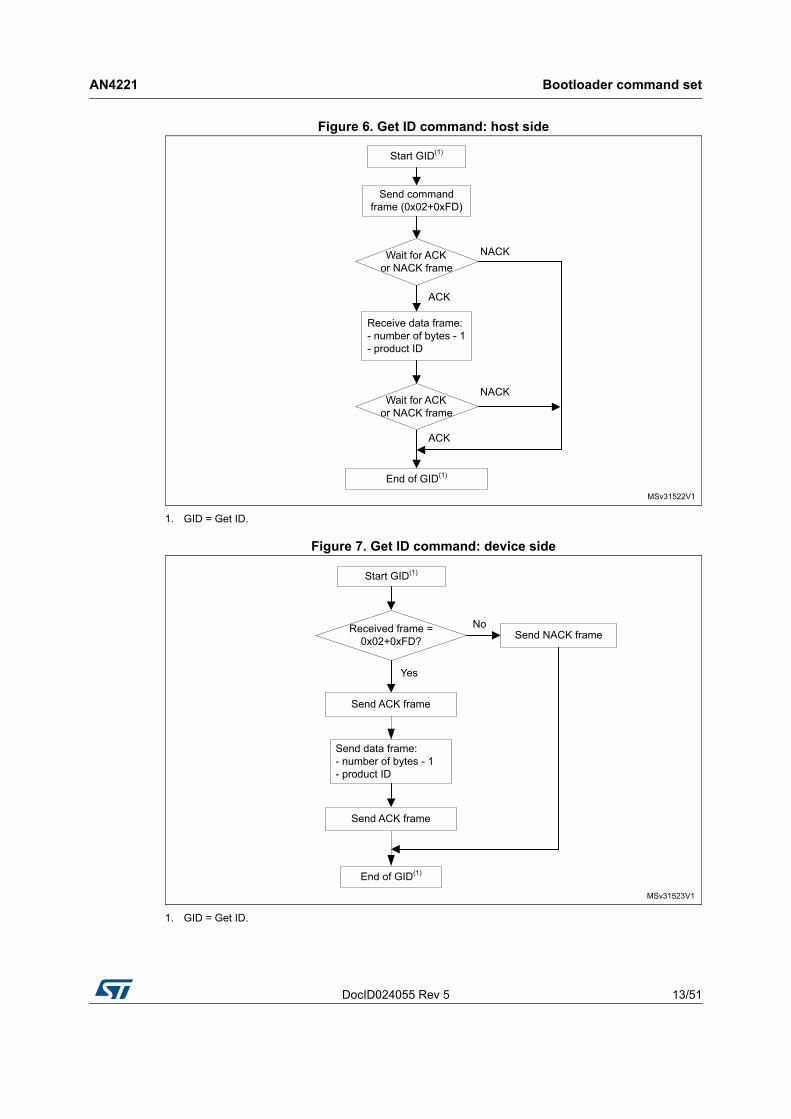
The Get ID command is used to get the version of the chip ID (identification). When the bootloader receives the command, it transmits the product ID to the host.
The STM32 device sends the bytes as follows:
• Byte 1: ACK
• Byte 2: N = the number of bytes - 1 (for STM32, N = 1), except for current byte and ACKs.
• Bytes 3-4: PID (product ID)
– byte 3 = MSB
– byte 4 = LSB
• Byte 5: ACK
DocID024055 Rev 5 13/51
AN4221 Bootloader command set
50
Figure 6. Get ID command: host side
1. GID = Get ID.
Figure 7. Get ID command: device side
1. GID = Get ID.

Bootloader command set AN4221
14/51 DocID024055 Rev 5
2.4 Read memory command
The Read Memory command is used to read data from any valid memory address.
When the bootloader receives the Read Memory command, it transmits the ACK byte to the application. The bootloader then waits for a 4-byte address (byte 1 is the address MSB, and byte 4 is the LSB) and a checksum byte, then it checks the received address. If the address is valid and the checksum is correct, the bootloader transmits an ACK byte; otherwise, it transmits a NACK byte and aborts the command.
If the address is valid and the checksum is correct, the bootloader waits for the number of bytes to be transmitted (N bytes), and for its complemented byte (checksum). If the checksum is correct, the bootloader transmits the needed data to the application, starting from the received address. If the checksum is not correct, it sends a NACK before aborting the command.
The host sends bytes to the STM32 as follows:
1. Bytes 1-2: 0x11+0xEE
2. Wait for ACK
3. Bytes 3-6: Start address (byte 3: MSB, byte 6: LSB)
4. Byte 7: Checksum: XOR (byte 3, byte 4, byte 5 and byte 6)
5. Wait for ACK
6. Byte 8: The number of bytes to be read - 1 (0 < N ≤ 255)
7. Byte 9: Checksum: XOR byte 8 (complement of byte 8)

DocID024055 Rev 5 15/51
AN4221 Bootloader command set
50
Figure 8. Read memory command: host side
1. RM = Read Memory.

Bootloader command set AN4221
16/51 DocID024055 Rev 5
Figure 9. Read memory command: device side
1. RM = Read Memory.

DocID024055 Rev 5 17/51
AN4221 Bootloader command set
50
2.5 Go command
The Go command is used to execute the downloaded code or any other code, by branching to an address specified by the application. When the bootloader receives the Go command, it transmits the ACK byte to the application. The bootloader then waits for a 4-byte address (byte 1 is the address MSB, and byte 4 is LSB) and a checksum byte, then checks the received address. If the address is valid and the checksum is correct, the bootloader transmits an ACK byte; otherwise, it transmits a NACK byte and aborts the command.
When the address is valid and the checksum is correct, the bootloader firmware performs the following:
1. Initializes the registers of the peripherals used by the bootloader to their default reset values
2. Initializes the user application's main stack pointer
3. Jumps to the memory location programmed in the received 'address + 4' (which corresponds to the address of the application's reset handler). For example, if the received address is 0x08000000, the bootloader jumps to the memory location programmed at address 0x08000004.
In general, the host should send the base address where the application to jump to is programmed.
Note: Jumping to the application only works if the user application correctly sets the vector table to point to the application address.
The host sends bytes to the STM32 as follows:
1. Byte 1: 0x21
2. Byte 2: 0xDE
3. Wait for ACK
4. Byte 3 to byte 6: start address
– byte 3: MSB
– byte 6: LSB
5. Byte 7: checksum: XOR (byte 3, byte 4, byte 5 and byte 6)
6. Wait for ACK

Bootloader command set AN4221
18/51 DocID024055 Rev 5
Figure 10. Go command: host side

DocID024055 Rev 5 19/51
AN4221 Bootloader command set
50
Figure 11. Go command: device side
Bootloader command set AN4221
20/51 DocID024055 Rev 5
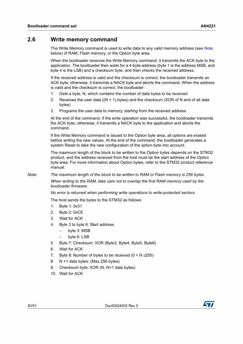
2.6 Write memory command
The Write Memory command is used to write data to any valid memory address (see Note: below) of RAM, Flash memory, or the Option byte area.
When the bootloader receives the Write Memory command, it transmits the ACK byte to the application. The bootloader then waits for a 4-byte address (byte 1 is the address MSB, and byte 4 is the LSB) and a checksum byte, and then checks the received address.
If the received address is valid and the checksum is correct, the bootloader transmits an ACK byte; otherwise, it transmits a NACK byte and aborts the command. When the address is valid and the checksum is correct, the bootloader:
1. Gets a byte, N, which contains the number of data bytes to be received
2. Receives the user data ((N + 1) bytes) and the checksum (XOR of N and of all data bytes)
3. Programs the user data to memory, starting from the received address
At the end of the command, if the write operation was successful, the bootloader transmits the ACK byte; otherwise, it transmits a NACK byte to the application and aborts the command.
If the Write Memory command is issued to the Option byte area, all options are erased before writing the new values. At the end of the command, the bootloader generates a system Reset to take the new configuration of the option byte into account.
The maximum length of the block to be written to the Option bytes depends on the STM32 product, and the address received from the host must be the start address of the Option byte area. For more information about Option bytes, refer to the STM32 product reference manual.
Note: The maximum length of the block to be written to RAM or Flash memory is 256 bytes.
When writing to the RAM, take care not to overlap the first RAM memory used by the bootloader firmware.
No error is returned when performing write operations to write-protected sectors.
The host sends the bytes to the STM32 as follows:
1. Byte 1: 0x31
2. Byte 2: 0xCE
3. Wait for ACK
4. Byte 3 to byte 6: Start address
– byte 3: MSB
– byte 6: LSB
5. Byte 7: Checksum: XOR (Byte3, Byte4, Byte5, Byte6)
6. Wait for ACK
7. Byte 8: Number of bytes to be received (0 < N ≤ 255)
8. N +1 data bytes: (Max 256 bytes)
9. Checksum byte: XOR (N, N+1 data bytes)
10. Wait for ACK

DocID024055 Rev 5 21/51
AN4221 Bootloader command set
50
Figure 12. Write memory command: host side
1. WM = Write Memory.

Bootloader command set AN4221
22/51 DocID024055 Rev 5
Figure 13. Write memory command: device side
1. WM = Write Memory.
DocID024055 Rev 5 23/51
AN4221 Bootloader command set
50
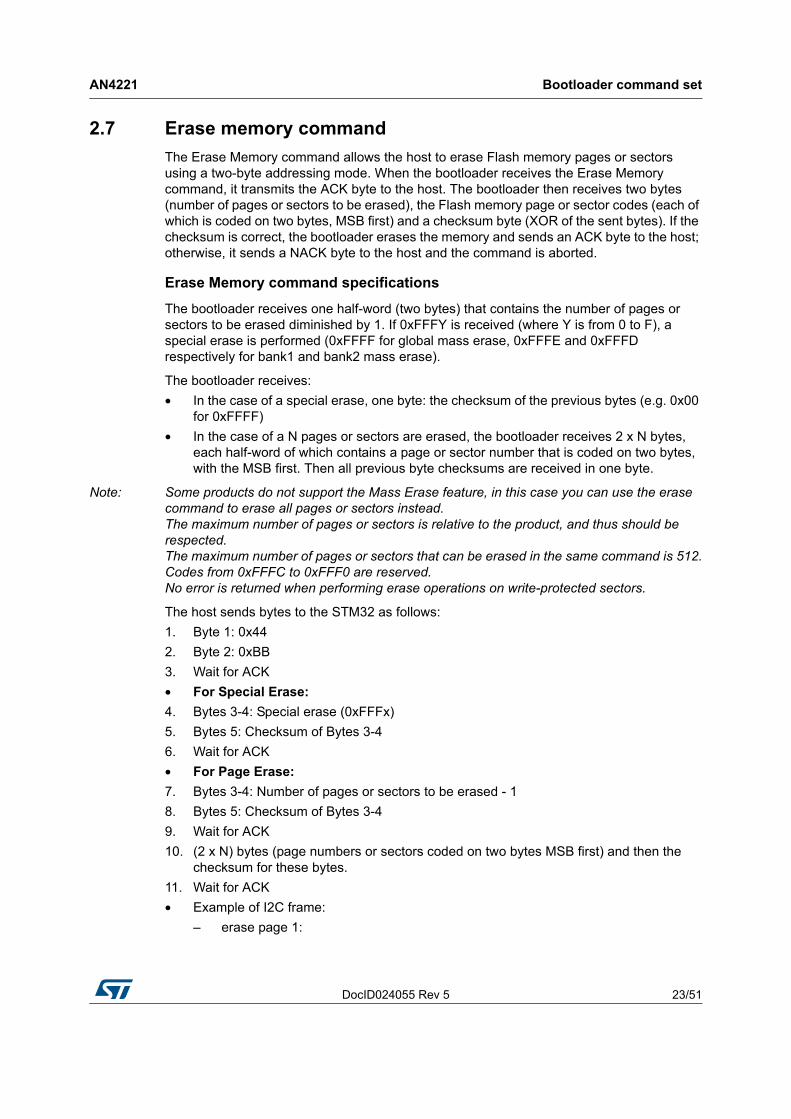
2.7 Erase memory command
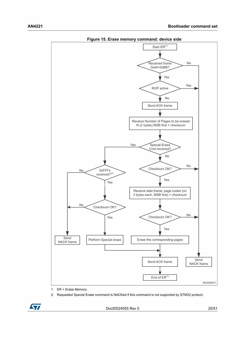
The Erase Memory command allows the host to erase Flash memory pages or sectors using a two-byte addressing mode. When the bootloader receives the Erase Memory command, it transmits the ACK byte to the host. The bootloader then receives two bytes (number of pages or sectors to be erased), the Flash memory page or sector codes (each of which is coded on two bytes, MSB first) and a checksum byte (XOR of the sent bytes). If the checksum is correct, the bootloader erases the memory and sends an ACK byte to the host; otherwise, it sends a NACK byte to the host and the command is aborted.
Erase Memory command specifications
The bootloader receives one half-word (two bytes) that contains the number of pages or sectors to be erased diminished by 1. If 0xFFFY is received (where Y is from 0 to F), a special erase is performed (0xFFFF for global mass erase, 0xFFFE and 0xFFFD respectively for bank1 and bank2 mass erase).
The bootloader receives:
• In the case of a special erase, one byte: the checksum of the previous bytes (e.g. 0x00 for 0xFFFF)
• In the case of a N pages or sectors are erased, the bootloader receives 2 x N bytes, each half-word of which contains a page or sector number that is coded on two bytes, with the MSB first. Then all previous byte checksums are received in one byte.
Note: Some products do not support the Mass Erase feature, in this case you can use the erase command to erase all pages or sectors instead. The maximum number of pages or sectors is relative to the product, and thus should be respected. The maximum number of pages or sectors that can be erased in the same command is 512. Codes from 0xFFFC to 0xFFF0 are reserved. No error is returned when performing erase operations on write-protected sectors.
The host sends bytes to the STM32 as follows:
1. Byte 1: 0x44
2. Byte 2: 0xBB
3. Wait for ACK
• For Special Erase:
4. Bytes 3-4: Special erase (0xFFFx)
5. Bytes 5: Checksum of Bytes 3-4
6. Wait for ACK
• For Page Erase:
7. Bytes 3-4: Number of pages or sectors to be erased - 1
8. Bytes 5: Checksum of Bytes 3-4
9. Wait for ACK
10. (2 x N) bytes (page numbers or sectors coded on two bytes MSB first) and then the checksum for these bytes.
11. Wait for ACK
• Example of I2C frame:
– erase page 1:
Bootloader command set AN4221
24/51 DocID024055 Rev 5
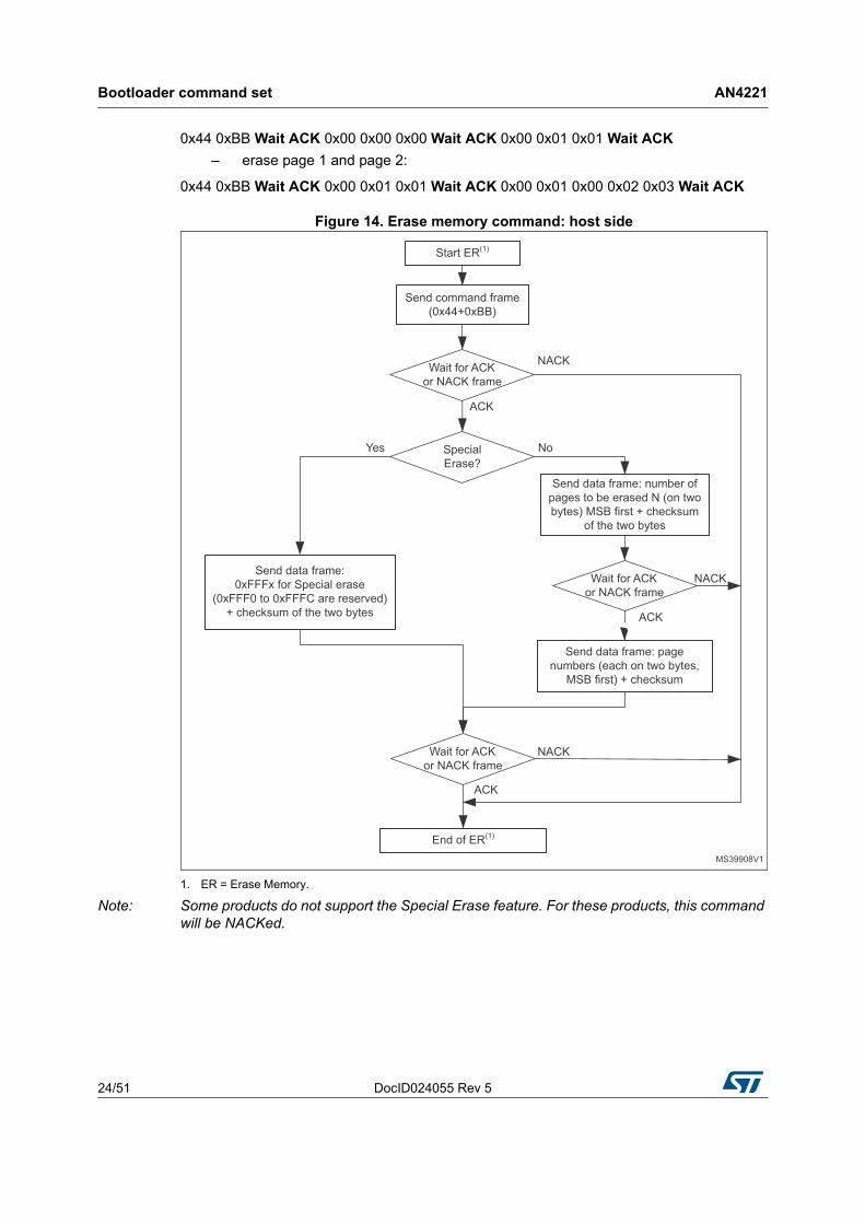
0x44 0xBB Wait ACK 0x00 0x00 0x00 Wait ACK 0x00 0x01 0x01 Wait ACK
– erase page 1 and page 2:
0x44 0xBB Wait ACK 0x00 0x01 0x01 Wait ACK 0x00 0x01 0x00 0x02 0x03 Wait ACK
Figure 14. Erase memory command: host side
1. ER = Erase Memory.
Note: Some products do not support the Special Erase feature. For these products, this command will be NACKed.
DocID024055 Rev 5 25/51
AN4221 Bootloader command set
50
Figure 15. Erase memory command: device side
1. ER = Erase Memory.
2. Requested Special Erase command is NACKed if this command is not supported by STM32 product.
Bootloader command set AN4221
26/51 DocID024055 Rev 5
2.8 Write protect command
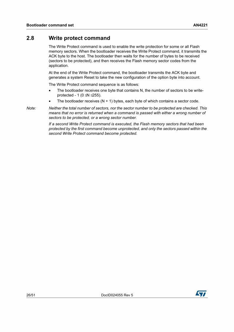
The Write Protect command is used to enable the write protection for some or all Flash memory sectors. When the bootloader receives the Write Protect command, it transmits the ACK byte to the host. The bootloader then waits for the number of bytes to be received (sectors to be protected), and then receives the Flash memory sector codes from the application.
At the end of the Write Protect command, the bootloader transmits the ACK byte and generates a system Reset to take the new configuration of the option byte into account.
The Write Protect command sequence is as follows:
• The bootloader receives one byte that contains N, the number of sectors to be write-protected - 1 (0 ≤ N ≤ 255).
• The bootloader receives (N + 1) bytes, each byte of which contains a sector code.
Note: Neither the total number of sectors, nor the sector number to be protected are checked. This means that no error is returned when a command is passed with either a wrong number of sectors to be protected, or a wrong sector number.
If a second Write Protect command is executed, the Flash memory sectors that had been protected by the first command become unprotected, and only the sectors passed within the second Write Protect command become protected.
DocID024055 Rev 5 27/51
AN4221 Bootloader command set
50
Figure 16. Write protect command: host side
1. WP = Write Protect.

Bootloader command set AN4221
28/51 DocID024055 Rev 5
Figure 17. Write protect command: device side
1. WP = Write Protect.

DocID024055 Rev 5 29/51
AN4221 Bootloader command set
50
2.9 Write unprotect command
The Write Unprotect command is used to disable the write protection of all Flash memory sectors. When the bootloader receives the Write Unprotect command, it transmits the ACK byte to the host. The bootloader then disables the write protection of all Flash memory sectors, and transmits the ACK byte.
A system reset is generated to take the new configuration of the option byte into account.
Figure 18. Write unprotect command: host side
1. WPUN = Write Unprotect.

Bootloader command set AN4221
30/51 DocID024055 Rev 5
Figure 19. Write unprotect command: device side
1. WPUN = Write Unprotect.
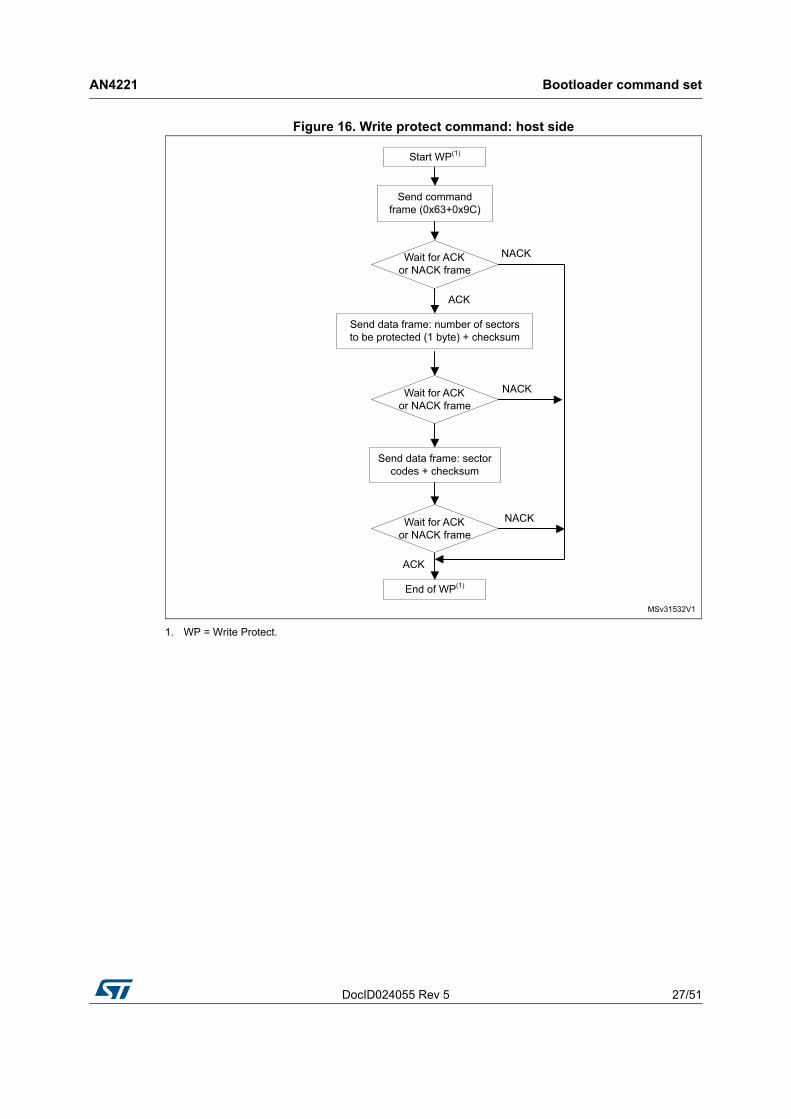
2.10 Readout protect command
The Readout Protect command is used to enable the Flash memory read protection. When the bootloader receives the Readout Protect command, it transmits the ACK byte to the host, and enables the read protection for the Flash memory.
At the end of the Readout Protect command, the bootloader transmits the ACK byte and generates a system Reset to take the new configuration of the option byte into account.
DocID024055 Rev 5 31/51
AN4221 Bootloader command set
50
Figure 20. Readout protect command: host side
1. RDP_PRM = Readout Protect.
Figure 21. Readout protect command: device side
1. RDP_PRM = Readout Protect.
Bootloader command set AN4221
32/51 DocID024055 Rev 5
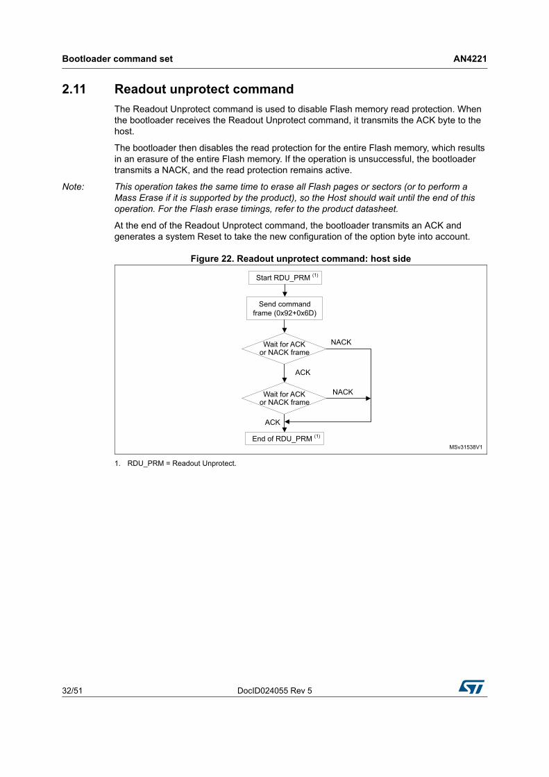
2.11 Readout unprotect command
The Readout Unprotect command is used to disable Flash memory read protection. When the bootloader receives the Readout Unprotect command, it transmits the ACK byte to the host.
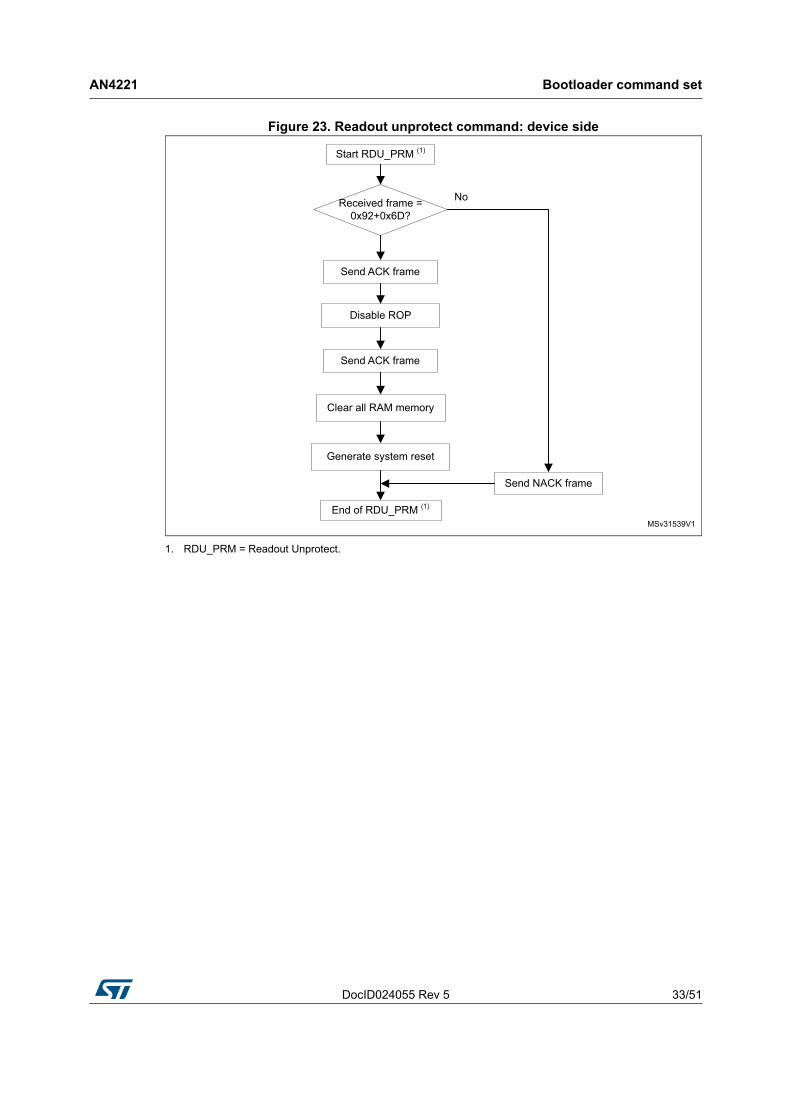
The bootloader then disables the read protection for the entire Flash memory, which results in an erasure of the entire Flash memory. If the operation is unsuccessful, the bootloader transmits a NACK, and the read protection remains active.
Note: This operation takes the same time to erase all Flash pages or sectors (or to perform a Mass Erase if it is supported by the product), so the Host should wait until the end of this operation. For the Flash erase timings, refer to the product datasheet.
At the end of the Readout Unprotect command, the bootloader transmits an ACK and generates a system Reset to take the new configuration of the option byte into account.
Figure 22. Readout unprotect command: host side
1. RDU_PRM = Readout Unprotect.
DocID024055 Rev 5 33/51
AN4221 Bootloader command set
50
Figure 23. Readout unprotect command: device side
1. RDU_PRM = Readout Unprotect.
Bootloader command set AN4221
34/51 DocID024055 Rev 5
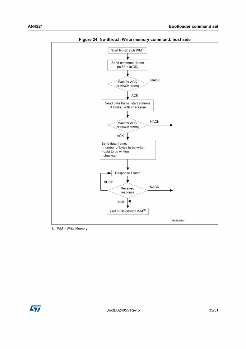
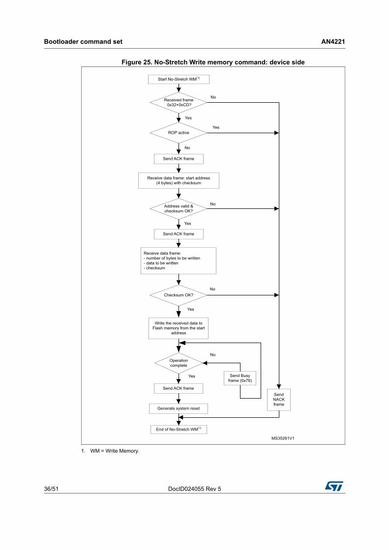
2.12 No-Stretch Write memory command
The No-Stretch Write Memory command is used to write data to any valid memory area.
When the bootloader receives the No-Stretch Write Memory command, it transmits the ACK byte to the application. The bootloader then waits for a 4-byte address (byte 1 is the address MSB, and byte 4 is the LSB) and a checksum byte, and then checks the received address.
If the received address is valid and the checksum is correct, the bootloader transmits an ACK byte; otherwise, it transmits a NACK byte and aborts the command. When the address is valid and the checksum is correct, the bootloader:
1. Gets a byte, N, which contains the number of data bytes to be received
2. Receives the user data ((N + 1) bytes) and the checksum (XOR of N and of all data bytes)
3. Programs the user data to memory, starting from the received address
4. Returns a Busy state (0x76) while operation is ongoing
At the end of the command, if the write operation was successful, the bootloader transmits the ACK byte; otherwise, it transmits a NACK byte to the application and aborts the command.
Note: If the No-Stretch Write Memory command is issued to the Option byte area, the bootloader generates a system Reset to take the new configuration of the option byte into account.
The maximum length of the block to be written to memory is 256 bytes except for the Option bytes the maximum length depends on the STM32 product, and the address received from the host must be the start address of the Option byte area. For more information, refer to the STM32 product reference manual.
No error is returned when performing write operations to write-protected sectors.
The host sends the bytes to the STM32 as follows:
1. Byte 1: 0x32
2. Byte 2: 0xCD
3. Wait for ACK
4. Byte 3 to byte 6: Start address
– byte 3: MSB
– byte 6: LSB
5. Byte 7: Checksum: XOR (Byte3, Byte4, Byte5, Byte6)
6. Wait for ACK
7. Byte 8: Number of bytes to be received (0 < N ≤ 255)
8. N +1 data bytes: (Max 256 bytes)
9. Checksum byte: XOR (N, N+1 data bytes)
10. Wait for ACK (if Busy keep polling on ACK/NACK)
DocID024055 Rev 5 35/51
AN4221 Bootloader command set
50
Figure 24. No-Stretch Write memory command: host side
1. WM = Write Memory.
Bootloader command set AN4221
36/51 DocID024055 Rev 5
Figure 25. No-Stretch Write memory command: device side
1. WM = Write Memory.
DocID024055 Rev 5 37/51
AN4221 Bootloader command set
50
2.13 No-Stretch Erase memory command
The No-Stretch Erase Memory command allows the host to erase Flash memory pages or sectors using a two-byte addressing mode. When the bootloader receives the Erase Memory command, it transmits the ACK byte to the host. The bootloader then receives two bytes (number of pages or sectors to be erased), the Flash memory page or sector codes (each of which is coded on two bytes, MSB first) and a checksum byte (XOR of the sent bytes). If the checksum is correct, the bootloader erases the memory (returns Busy state (0x76) while operation is ongoing) then sends an ACK byte to the host; otherwise, it sends a NACK byte to the host and the command is aborted.
No-Stretch Erase Memory command specifications
The bootloader receives one half-word (two bytes) that contains the number of pages or sectors to be erased diminished by 1. If 0xFFFY is received (where Y is from 0 to F), a special erase is performed (0xFFFF for global mass erase, 0xFFFE and 0xFFFD respectively for bank1 and bank2 mass erase).
The bootloader receives:
• In the case of a special erase, one byte: the checksum of the previous bytes ( e.g. 0x00 for 0xFFFF)
• In the case of a N pages or sectors are erased, the bootloader receives (2 x N ) bytes, each half-word of which contains a page or sector number that is coded on two bytes, with the MSB first. Then all previous byte checksums are received in one byte.
Note: Some products do not support the Mass Erase feature, in this case you can use the erase command to erase all pages or sectors instead. The maximum number of pages or sectors is relative to the product, and thus should be respected. The maximum number of pages or sectors that can be erased in the same command is 512. Codes from 0xFFFC to 0xFFF0 are reserved. No error is returned when performing erase operations on write-protected sectors.
The host sends bytes to the STM32 as follows:
1. Byte 1: 0x45
2. Byte 2: 0xBA
3. Wait for ACK
• For Special Erase:
4. Bytes 3-4: Special erase (0xFFFx)
5. Bytes 5: Checksum of Bytes 3-4
6. Wait for ACK (if Busy keep polling on ACK/NACK)
• For Page Erase:
7. Bytes 3-4: Number of pages or sectors to be erased - 1
8. Bytes 5: Checksum of Bytes 3-4
9. Wait for ACK
10. (2 x N) bytes (page numbers or sectors coded on two bytes MSB first) and then the checksum for these bytes.
11. Wait for ACK (if Busy keep polling on ACK/NACK)
• Example of I2C frame:
– erase page 1:

Bootloader command set AN4221
38/51 DocID024055 Rev 5
0x45 0xBA Wait ACK 0x00 0x00 0x00 Wait ACK 0x00 0x01 0x01 Wait ACK
– erase page 1 and page 2:
0x45 0xBA Wait ACK 0x00 0x01 0x01 Wait ACK 0x00 0x01 0x00 0x02 0x03 Wait ACK
Figure 26. No-Stretch Erase memory command: host side
1. ER = Erase Memory.
Note: Some products do not support the Special Erase feature. For these products, this command will be NACKed.

DocID024055 Rev 5 39/51
AN4221 Bootloader command set
50
Figure 27. No-Stretch Erase memory command: device side
1. ER = Erase Memory.
2. Requested Special Erase command is NACKed if this command is not supported by STM32 product.

Bootloader command set AN4221
40/51 DocID024055 Rev 5
2.14 No-Stretch Write protect command
The No-Stretch Write Protect command is used to enable the write protection for some or all Flash memory sectors. When the bootloader receives the Write Protect command, it transmits the ACK byte to the host. The bootloader then waits for the number of bytes to be received (sectors to be protected), then receives the Flash memory sector codes from the application and returns Busy state (0x76) while operation is ongoing.
At the end of the No-Stretch Write Protect command, the bootloader transmits the ACK byte and generates a system Reset to take the new configuration of the option byte into account.
The Write Protect command sequence is as follows:
• The bootloader receives one byte that contains N, the number of sectors to be write-protected - 1 (0 ≤ N ≤ 255).
• The bootloader receives (N + 1) bytes, each byte of which contains a sector code.
Note: Neither the total number of sectors, nor the sector number to be protected are checked. This means that no error is returned when a command is passed with either a wrong number of sectors to be protected, or a wrong sector number.
If a second Write Protect command is executed, the Flash memory sectors that had been protected by the first command become unprotected, and only the sectors passed within the second Write Protect command become protected.

DocID024055 Rev 5 41/51
AN4221 Bootloader command set
50
Figure 28. No-Stretch Write protect command: host side
1. WP = Write Protect.

Bootloader command set AN4221
42/51 DocID024055 Rev 5
Figure 29. No-Stretch Write protect command: device side
1. WP = Write Protect.

DocID024055 Rev 5 43/51
AN4221 Bootloader command set
50
2.15 No-Stretch Write unprotect command
The No-Stretch Write Unprotect command is used to disable the write protection of all Flash memory sectors. When the bootloader receives the Write Unprotect command, it transmits the ACK byte to the host. The bootloader then disables the write protection of all Flash memory sectors, returns Busy state (0x76) while operation is ongoing. At the end it transmits the ACK byte.
A system reset is generated to take the new configuration of the option byte into account.
Figure 30. No-Stretch Write unprotect command: host side
1. WPUN = Write Unprotect.

Bootloader command set AN4221
44/51 DocID024055 Rev 5
Figure 31. No-Stretch Write unprotect command: device side
1. WPUN = Write Unprotect.
2.16 No-Stretch Readout protect command
The No-Stretch Readout Protect command is used to enable the Flash memory read protection. When the bootloader receives the Readout Protect command, it transmits the ACK byte to the host, enables the read protection for the Flash memory and returns Busy state (0x76) while operation is ongoing.
At the end of the No-Stretch Readout Protect command, the bootloader transmits the ACK byte and generates a system Reset to take the new configuration of the option byte into account.

DocID024055 Rev 5 45/51
AN4221 Bootloader command set
50
Figure 32. NoStretch Readout protect command: host side
1. RDP_PRM = Readout Protect.

Bootloader command set AN4221
46/51 DocID024055 Rev 5
Figure 33. No-Stretch Readout protect command: device side
1. RDP_PRM = Readout Protect.
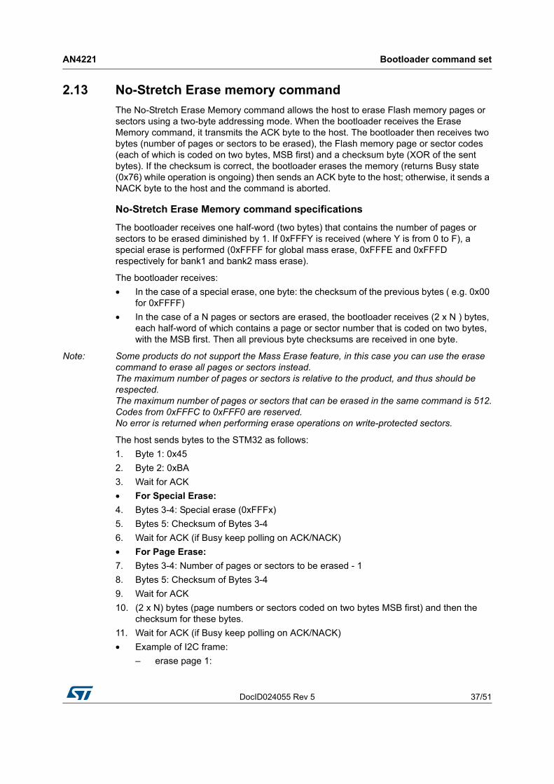
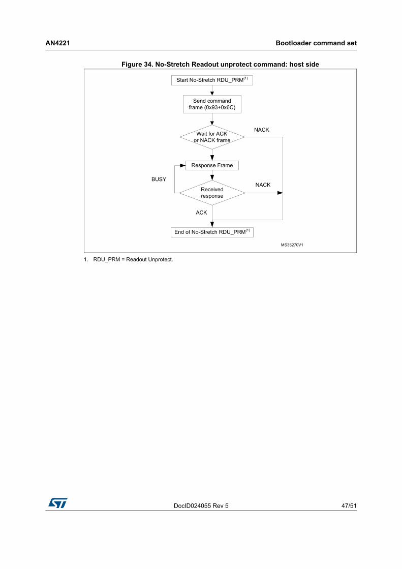
2.17 No-Stretch Readout unprotect command
The No-Stretch Readout Unprotect command is used to disable Flash memory read protection. When the bootloader receives the Readout Unprotect command, it transmits the ACK byte to the host.
The bootloader then disables the read protection for the entire Flash memory, which results in an erasure of the entire Flash memory and returns Busy state (0x76) while operation is ongoing. If the operation is unsuccessful, the bootloader transmits a NACK, and the read protection remains active.
At the end of the No-Stretch Readout Unprotect command, the bootloader transmits an ACK and generates a system Reset to take the new configuration of the option byte into account.
DocID024055 Rev 5 47/51
AN4221 Bootloader command set
50
Figure 34. No-Stretch Readout unprotect command: host side
1. RDU_PRM = Readout Unprotect.
Bootloader command set AN4221
48/51 DocID024055 Rev 5
Figure 35. No-Stretch Readout unprotect command: device side
1. RDU_PRM = Readout Unprotect.

DocID024055 Rev 5 49/51
AN4221 Bootloader protocol version evolution
50
3 Bootloader protocol version evolution
Table 3 lists the bootloader versions.
Table 3. Bootloader protocol versions
Version Description
V1.0 Initial protocol version.
V1.1
This version implements new I2C commands: No-Stretch Write Memory, No-Stretch Erase Memory, No-Stretch Write Protect, No-Stretch Write Unprotect, No-Stretch ReadOut Protect and No-Stretch ReadOut Unprotect.

Revision history AN4221
50/51 DocID024055 Rev 5
4 Revision history
Table 4. Document revision history
Date Revision Changes
18-Jan-2013 1 Initial release.
02-May-2014 2
Updated list of Applicable products in Table 1.
Updated set of commands in Table 2.
Updated Section 2: Bootloader command set.
Added Section 2.12, Section 2.13, Section 2.14, Section 2.15, Section 2.16 and Section 2.17.
Added new Protocol version in Table 3.
08-Oct-2015 3
Updated Introduction, Section 2: Bootloader command set, Section 2.7: Erase memory command and Section 2.13: No-Stretch Erase memory command.
Updated Table 1: Applicable products and Table 2: I2C bootloader commands.
Updated Figure 14: Erase memory command: host side, Figure 15: Erase memory command: device side, Figure 26: No-Stretch Erase memory command: host side and Figure 27: No-Stretch Erase memory command: device side.
19-Oct-2016 4 Updated Introduction and Table 1: Applicable products.
15-Mar-2017 5 Updated Table 1: Applicable products.

DocID024055 Rev 5 51/51
AN4221
51
IMPORTANT NOTICE – PLEASE READ CAREFULLY
STMicroelectronics NV and its subsidiaries (“ST”) reserve the right to make changes, corrections, enhancements, modifications, and improvements to ST products and/or to this document at any time without notice. Purchasers should obtain the latest relevant information on ST products before placing orders. ST products are sold pursuant to ST’s terms and conditions of sale in place at the time of order acknowledgement.
Purchasers are solely responsible for the choice, selection, and use of ST products and ST assumes no liability for application assistance or the design of Purchasers’ products.
No license, express or implied, to any intellectual property right is granted by ST herein.
Resale of ST products with provisions different from the information set forth herein shall void any warranty granted by ST for such product.
ST and the ST logo are trademarks of ST. All other product or service names are the property of their respective owners.
Information in this document supersedes and replaces information previously supplied in any prior versions of this document.
© 2017 STMicroelectronics – All rights reserved