an4480, permanent magnet synchronous motor with · pdf filepermanent magnet synchronous motor...
TRANSCRIPT

Freescale SemiconductorApplication Note
AN4480Rev. 0, 03/2012
Table of ContentsPower Architecture MPC5554 and eTPU advantages and features . . . . . . . . . . . . . . . . . . . . . . . . . . . . . . . . . . . . . . 2
1.1 Power Architecture MPC5554 microprocessor . . . . 21.2 eTPU module. . . . . . . . . . . . . . . . . . . . . . . . . . . . . . 3Target motor theory . . . . . . . . . . . . . . . . . . . . . . . . . . . . . 3
2.1 Digital control of PMSM. . . . . . . . . . . . . . . . . . . . . . 42.2 Vector control of PMSM. . . . . . . . . . . . . . . . . . . . . . 52.3 Resolver . . . . . . . . . . . . . . . . . . . . . . . . . . . . . . . . . 5System concept . . . . . . . . . . . . . . . . . . . . . . . . . . . . . . . . 6
3.1 System outline. . . . . . . . . . . . . . . . . . . . . . . . . . . . . 63.2 Application description. . . . . . . . . . . . . . . . . . . . . . . 73.3 Hardware implementation and application setup. . 10Software design. . . . . . . . . . . . . . . . . . . . . . . . . . . . . . . 13
4.1 CPU software flowchart . . . . . . . . . . . . . . . . . . . . . 154.2 Application state diagram . . . . . . . . . . . . . . . . . . . 174.3 eTPU application API . . . . . . . . . . . . . . . . . . . . . . 204.4 eTPU block diagram . . . . . . . . . . . . . . . . . . . . . . . 264.5 eTPU timing. . . . . . . . . . . . . . . . . . . . . . . . . . . . . . 33Implementation notes . . . . . . . . . . . . . . . . . . . . . . . . . . 36
5.1 Scaling of quantities . . . . . . . . . . . . . . . . . . . . . . . 36Microprocessor usage . . . . . . . . . . . . . . . . . . . . . . . . . . 36Summary and conclusions . . . . . . . . . . . . . . . . . . . . . . 36References . . . . . . . . . . . . . . . . . . . . . . . . . . . . . . . . . . 37
Permanent Magnet Synchronous Motor with Resolver, Vector Control, Driven by eTPU on MPC5500Covers MPC5500, MPC5600, and all eTPU-equipped devicesby: Milan Brejl
System Application EngineersRoznov Czech System Center
This application note describes the design of a 3-phase Permanent Magnet Synchronous Motor (PMSM) speed and torque vector control drive based on Freescale’s Power Architecture MPC5500 microprocessor. The application design takes advantage of the enhanced time processing unit (eTPU) module, which is used as a motor control co-processor. The eTPU handles the motor control processing, eliminating the microprocessor overhead for other duties.
This application note was based on AN3206. AN3206 describes a PMSM drive using a quadrature encoder, while this document describes the same motor drive using a resolver.
PMSMs are very popular in a wide array of applications. Compared with a DC motor, the PMSM misses a commutator and so it is more reliable than the DC motor. The PMSM also has advantages when compared to an AC induction motor. PMSM generate the rotor magnetic flux with rotor magnets, so achieve higher efficiency. Therefore PMSM are used in electric and hybrid vehicles, high-end white goods (refrigerators, washing machines, dishwashers, etc.), high-end pumps, fans and
1
2
3
4
5
678
© Freescale Semiconductor, Inc., 2012. All rights reserved.

Power Architecture MPC5554 and eTPU advantages and features
in other appliances, which require high reliability and efficiency.
The concept of the application is to create a vector control PMSM driver with optional speed closed-loop, using a resolver. It serves as an example of a PMSM vector control system design using a Freescale microprocessor with the eTPU. It also illustrates the usage of dedicated motor control eTPU functions that are included in the Freescale AC motor control eTPU function set.
This application note also includes basic motor theory, system design concept, hardware implementation, and microprocessor and eTPU software design, including the FreeMASTER visualization tool.
Figure 1. MPC5554 controller board, power stage with MC33937, and TGT2-0032-30-24 PMSM
1 Power Architecture MPC5554 and eTPU advantages and features
1.1 Power Architecture MPC5554 microprocessorThe MPC5554 microcontroller, which is used in this application, belongs to a family of powertrain microcontrollers based on the Power Architecture Book E architecture. The application can be easily ported to any other MPC5500 or MPC5600 device featuring the eTPU module. The eTPU handles all
Permanent Magnet Synchronous Motor with Resolver, Vector Control, Driven by eTPU on MPC5500, Rev. 0
Freescale Semiconductor2

Target motor theory
real-time motor control tasks, minimizing the CPU usage. Except the eTPU, the following peripheral modules are utilized:
• Enhanced Direct Memory Access controller (eDMA)
• Enhanced Queued Analog-to-Digital Converter (eQADC)
• Deserial Serial Peripheral Interface (DSPI) modules
• Enhanced Serial Communication Interface (eSCI) modules
For more information about MPC5554, refer to Reference 1.
1.2 eTPU moduleThe eTPU is an intelligent, semi-autonomous co-processor designed for timing control, I/O handling, serial communications, motor control, and engine control applications. It operates in parallel with the host CPU. The eTPU processes instructions and real-time input events, performs output waveform generation, and accesses shared data without the host CPU’s intervention. Consequently, the host CPU setup and service times for each timer event are minimized or eliminated.
The eTPU on the MPC5554 microcontroller has two engines with up to 32 timer channels for each. In addition it has 16 Kbytes of code memory and 3 Kbytes of data memory that stores software modules downloaded at boot time and that can be mixed and matched as required for any specific application.
The eTPU provides more specialized timer processing than the host CPU can achieve. This is partially due to the eTPU implementation, which includes specific instructions for handling and processing time events. In addition, channel conditions are available for use by the eTPU processor, thus eliminating many branches. The eTPU creates no host CPU overhead for servicing timing events.
For more information, refer to Reference 7.
2 Target motor theory
Figure 2. Permanent magnet AC machine — cross section
Stator
Stator winding(in slots)
Shaft
Rotor
Air gap
Permanent magnets
Permanent Magnet Synchronous Motor with Resolver, Vector Control, Driven by eTPU on MPC5500, Rev. 0
Freescale Semiconductor 3

Target motor theory
Permanent magnet ac (PMAC) machines provide automotive actuator designers with a unique set of features and capabilities. There are two principal classes of permanent magnet ac machines, the first type are sinusoidally excited, so called permanent magnet synchronous motors (PMSM), and the second type are trapezoidaly excited machines, so called brushless DC (BLDC) motors. The conceived construction differences are that while stator windings of trapezoidal PMAC machines are concentrated into narrow-phase pole, the windings of a sinusoidal machine are typically distributed over multiple slots in order to approximate a sinusoidal distribution. These differences in construction are reflected in their corresponding motion characteristics as well. This implies the consequence that the first type of PMAC provides sinusoidal back-electromotive force (back-EMF) generation, and the second type provides trapezoidal back-EMF.
The PMSM machines enjoy unique advantages of unsurpassed efficiency and power density characteristics which are primarily responsible for their wide appeal. On the other hand, PMSM machines are synchronous which certainly requires accompanying power electronics, but it also provides the basis for achieving high-quality actuator control. The torque ripple associated with sinusoidal PMAC (PMSM) machines is generally less than that developed in trapezoidal machines, providing one the reasons that sinusoidal motors are preferred in high performance motion control application such as electro-mechanical braking. This application note targets the PMSM only.
2.1 Digital control of PMSMFor the common 3-phase PMSM motor, a standard 3-phase power stage is used (see Figure 3). The power stage utilizes six power transistors that operate in complementary mode.
Figure 3. 3-phase power stage
The inverter consists of three half-bridge units where the upper and lower switches are controlled complementarily, meaning when the upper one is turned on, the lower one must be turned off, and vice versa. Because the power device’s turn-off time is longer than its turn-on time, some dead time must be inserted between turning off one transistor of the half-bridge, and turning on its complementary device. The output voltage is mostly created by a Pulse Width Modulation (PWM) technique. The 3-phase voltage waves are shifted 120o to one another, thus a 3-phase motor can be supplied.
Q1
PWM_Q5
Q6Q4
C1
Phase_C
PWM_Q1
PWM_Q4
PWM_Q3
Phase_B
GND
Q2
UDCB
PWM_Q2
Phase_A
Q3
PWM_Q6
Q5
Permanent Magnet Synchronous Motor with Resolver, Vector Control, Driven by eTPU on MPC5500, Rev. 0
Freescale Semiconductor4

Target motor theory
2.2 Vector control of PMSMVector Control is an elegant method of controlling the permanent magnet synchronous motor (PMSM), where field oriented theory is used to control space vectors of magnetic flux, current, and voltage. It is possible to set up the co-ordinate system to decompose the vectors into an electro-magnetic field generating part and a torque generating part. Then the structure of the motor controller (Vector Control controller) is almost the same as for a separately excited DC motor, which simplifies the control of PMSM. This Vector Control technique was developed in the past especially to achieve similar excellent dynamic performance of PMSM.
As explained in Figure 4, the choice has been made of a widely used current control with an inner position closed loop. In this method, the decomposition of the field generating part and the torque generating part of the stator current allows separate control of the magnetic flux and the torque. In order to do so, we need to set up the rotary co-ordinate system connected to the rotor magnetic field. This co-ordinate system is generally called “d-q reference co-ordinate system”. For more information, refer to Reference 13.
Figure 4. PMSM vector control current loop block diagram
2.3 ResolverThe PMSM motor application uses the resolver for rotor position sensing. Resolver hardware can be viewed as two inductive position sensors, which, upon a supplied sinusoidal-shaped signal on input, generate two sinusoidal signals on output. The output signals’ amplitudes depend on the position of the shaft. The amplitude of one signal amplitude is proportional to the sine, and the amplitude of the other to the cosine, of the shaft angle position.
alpha
beta
DC
-Bus
Rip
ple
Elim
inationu_alpha
u_beta
Invers
eP
ark
Tra
nsfo
rm
u_q_lin
u_d_lin
Decouplin
g
i_alpha
i_betaPark
Tra
nsfo
rmsin
_th
eta
co
s_
the
ta
i_q
u_q
u_d
i_d_required
i_dC
lark
eT
ransfo
rm
i_a
i_c
SinCos
i_q_required
PI
i_d
i_q
u_dc_busPMSMVC
PI
i_b
position_counterscaling
theta
omega_actual
FeedForward
Circle
Lim
itation
Permanent Magnet Synchronous Motor with Resolver, Vector Control, Driven by eTPU on MPC5500, Rev. 0
Freescale Semiconductor 5

System concept
Figure 5 Resolver operation principle
A more detailed description of the resolver operation can be found in [8].
2.3.1 Position alignmentThe resolver gives an absolute position, and alignment is not necessary if an offset between the resolver zero-degree position and the motor zero-degree position is hard-coded in the application. But that is not the case in this application. The motor position alignment is done before the motor is started. The motor is powered by a defined static voltage pattern and the rotor aligns to the zero-degree position. The read resolver position is then taken as the offset between the motor and the resolver.
3 System concept
3.1 System outlineThe system is designed to drive a 3-phase PMSM. The application meets the following performance specifications:
• Voltage control of a PMSM using quadrature encoder ES28-6-1024-05-D-R
• Targeted at MPC5554 Controller Board (MPC5554CB), 10Amps, 3-Phase Power Stage with MC33937, and TGT2-0032-30-24 Permanent Magnet Synchronous Motor (PMSM)
• Control technique incorporates:
— PMSM vector control with optional speed-closed loop
— Both directions of rotation
— 4-quadrant operation
— Rotor alignment to the start position
— Minimum speed of 50 RPM
0 0.001 0.002 0.003 0.004 0.005 0.006 0.007 0.008 0.009 0.010 0.001 0.002 0.003 0.004 0.005 0.006 0.007 0.008 0.009 0.01
Sinusoidal Voltage
0 0.001 0.002 0.003 0.004 0.005 0.006 0.007 0.008 0.009 0.010 0.001 0.002 0.003 0.004 0.005 0.006 0.007 0.008 0.009 0.01
Cosinusoidal Voltage
0 0.001 0.002 0.003 0.004 0.005 0.006 0.007 0.008 0.009 0.010 0.001 0.002 0.003 0.004 0.005 0.006 0.007 0.008 0.009 0.01
0.5
-1
-0.5
0
1
0.5
-1
-0.5
0
1
-1
-0.5
0
0.5
1
-1
-0.5
0
0.5
1
-1
-0.5
0
0.5
1 Reference Voltage
resolver
Permanent Magnet Synchronous Motor with Resolver, Vector Control, Driven by eTPU on MPC5500, Rev. 0
Freescale Semiconductor6

System concept
— Maximum speed of 3000 RPM
• Manual interface (RUN/STOP switch, Up/Down push button control)
• FreeMASTER control interface (speed set-up, speed control/torque control choice)
• FreeMASTER monitor
— FreeMASTER graphical control page (required speed, required torque, actual motor speed, actual torque, start/stop status, fault status)
— FreeMASTER control scope (observes required and actual speeds and torques, applied voltage)
— Detail description of all eTPU functions used in the application (monitoring of channel registers and all function parameters in real time)
• DC bus over-current fault protection
• Error handling
3.2 Application descriptionA standard system concept is chosen for the motor control function (see Figure 6). The system incorporates the following hardware:
• MPC5554 Controller Board (MPC5554CB)
• 10Amps, 3-Phase Power Stage with MC33937
• TGT2-0032-30-24 PMSM
• Resolver RE-15-1-A14
• Power Supply 18V DC, 4Amps
Permanent Magnet Synchronous Motor with Resolver, Vector Control, Driven by eTPU on MPC5500, Rev. 0
Freescale Semiconductor 7

System concept
Figure 6. System concept
The eTPU module runs the main control algorithm. The 3-phase PWM output signals for a 3-phase inverter are generated, using vector control algorithm, according to feedback signals from quadrature encoder, actual values of phase currents, and the input variable values, provided by the microprocessor CPU. The DC-Bus voltage and phase currents are sampled by on-chip analog-to-digital converter (eQADC module). The transfer of measured samples from eQADC to eTPU DATA RAM is provided by the eDMA module.
The system processing is distributed between the CPU and the eTPU, which both run in parallel.
The CPU performs the following tasks:
• Handles the application state machine and sets the required speeds to the eTPU.
• Monitors the eTPU operation, and enables the FreeMASTER Recorder to sample eTPU internal variables with a sampling period 50us.
The eTPU performs the following tasks:
• Six eTPU channels (PWMF) are used to generate PWM output signals.
• One eTPU channel (RSLV) is used to generate a 50% duty-cycle PWM which, after low-pass filtering, becomes the resolver excitation signal.
• One eTPU channel (BC) is used for controlling the DC-bus break.
Permanent Magnet Synchronous Motor with Resolver, Vector Control, Driven by eTPU on MPC5500, Rev. 0
Freescale Semiconductor8

System concept
• One eTPU channel (ASAC) is used to trigger the on-chip AD convertor, and preprocess the sampled values. ASAC uses the eDMA to transfer eQADC conversion commands from eTPU DATA RAM into eQADC and to transfer the results of conversion from eQADC into eTPU DATA RAM.
• One eTPU channel (PWMMAC) is internally used to synchronize the PWM outputs and calculate space vector modulation, based on applied motor voltage vector Alpha-Beta coordinates.
• One eTPU channel (SC) is internally used to calculate the actual motor speed, and control a speed closed loop in case of speed vector control. The actual motor speed is calculated based on the QD position counter and QD last edge time. The required speed is provided by the CPU and passed through a ramp. The speed PI control algorithm processes the error between the required and actual speed. The PI controller output is passed to the PMSMVC eTPU function as a newly corrected value of the required motor torque.
• One eTPU channel (PMSMVC) is internally used to calculate the current vector control closed loop. It takes the values of actual phase currents from ASAC, the actual rotor position from QD, and the actual motor speed from SC. The phase currents are transferred to Alpha-Beta and D-Q coordinate system, using Clark and Park transformations. One PI control algorithm processes the error between the required and actual D-current, and another one the error between the required and the actual Q-current. The required value of the D-current, which is the flux controlling current, is set to zero. The required value of the Q-current, which is the torque controlling current, is either set directly by the CPU (torque vector control), or provided by the SC output (speed vector control). The PI controller outputs create the motor applied voltage vector, in D-Q coordinate system. It is transformed back to Alpha-Beta coordinate system and passed to PWM generator.
3.2.1 User interfaceThe application is interfaced by the following:
• RUN/STOP switch and Up/Down buttons on the MPC5554CB,
• FreeMASTER running on a PC connected to the MPC5554CB via USB cable. The MPC5554CB includes USB-to-serial gate.
The RUN/STOP switch, either on the board or on FreeMASTER Control Page, affects the application state and enables and disables the PWM phases. When the switch is on, the motor speed can be controlled either by the Up and Down buttons, or by the FreeMASTER graphical needle. The FreeMASTER also displays real-time values of application variables and their time behavior using scopes and recorders.
Permanent Magnet Synchronous Motor with Resolver, Vector Control, Driven by eTPU on MPC5500, Rev. 0
Freescale Semiconductor 9
System concept
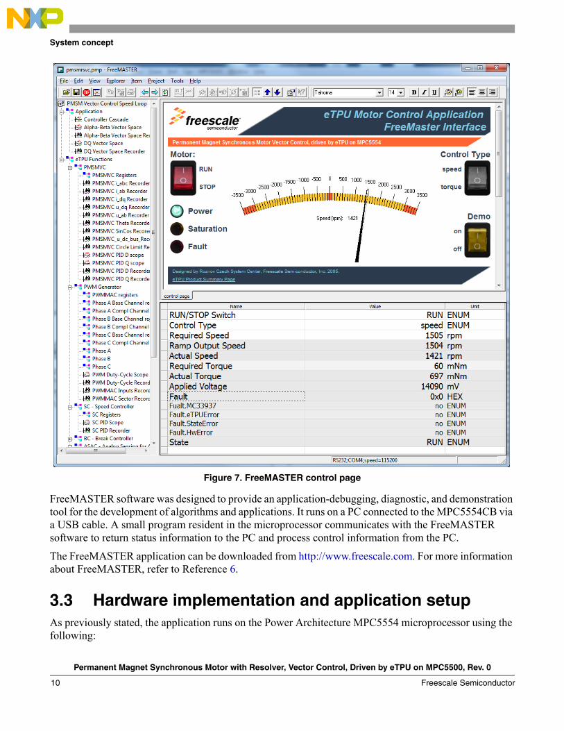
Figure 7. FreeMASTER control page
FreeMASTER software was designed to provide an application-debugging, diagnostic, and demonstration tool for the development of algorithms and applications. It runs on a PC connected to the MPC5554CB via a USB cable. A small program resident in the microprocessor communicates with the FreeMASTER software to return status information to the PC and process control information from the PC.
The FreeMASTER application can be downloaded from http://www.freescale.com. For more information about FreeMASTER, refer to Reference 6.
3.3 Hardware implementation and application setupAs previously stated, the application runs on the Power Architecture MPC5554 microprocessor using the following:
Permanent Magnet Synchronous Motor with Resolver, Vector Control, Driven by eTPU on MPC5500, Rev. 0
Freescale Semiconductor10

System concept
• MPC5554 Controller Board (MPC5554CB)
• 10Amps, 3-Phase Power Stage with MC33937
• TGT2-0032-30-24 PMSM
• Resolver RE-15-1-A14
• Power Supply 18V DC, 4Amps
Figure 8 shows the connection of these parts.
Figure 8. Connection of application parts
3.3.1 Power Architecture MPC5554 controller board (MPC5554CB)
The MPC5554CB features the MPC5554 microprocessor and circuitry for motor control applications:
• RUN/STOP switch and Up/Down buttons
• UNI3 motor control interface
• DSPI interface for MC33937
• Quadrature encoder connection
• Resolver connection
Permanent Magnet Synchronous Motor with Resolver, Vector Control, Driven by eTPU on MPC5500, Rev. 0
Freescale Semiconductor 11

System concept
• Serial-to-USB and USB connection for FreeMASTER
For schematic, refer to Reference 2.
3.3.2 10 A 3-phase power stage with MC33937The 3-Phase PMSM/BLDC Power Stage is based on MC33937 pre-driver integrated circuits. It operates on a wide range of input voltages from 8V up to 50V, being capable of driving currents of up to 10A. The 3-Phase Power Stage is an integral part of Freescale Semiconductor's embedded motion control series of development tools and can be used to drive 3-Phase BLDC, PMSM and ACIM motors. For more information and schematic, refer to Reference 3.
3.3.3 PMSM with resolverThe used motor is a TG drives low-voltage PMSM (TGT2-0032-30-24). The motor characteristics are in Table 1.
For more motor specifications, refer to Reference 4.
The resolver (RE-15-1-A14) is mounted to the motor. The basic resolver parameters are as follows:
• 1 pole pair
• Input frequency 10 kHz
• Input current 36 mA
• Maximum speed 20,000 rpm
For more resolver specifications, refer to Reference 5.
Table 1. PMSM motor characteristics
Characteristic Units Value
Nominal DC voltage V 18
Nominal torque Nm 0.30
Nominal speed rpm 3000
Nominal current A 5.20
Stall torque Nm 0.32
Stall current A 4.948
Torque constant Nm/A 0.065
Voltage constant V/1000 rpm 3.91
Resistance 2 ph. 0.583
Inductance 2 ph. mH 0.43
Pole-pairs — 6
Permanent Magnet Synchronous Motor with Resolver, Vector Control, Driven by eTPU on MPC5500, Rev. 0
Freescale Semiconductor12

Software design
3.3.4 Power supplyThe Power Stage board is powered by 18V/4A power supply and provides 12V supply for the MPC5554CB board.
4 Software designThis section describes the software design of the PMSM vector control drive application. The system processing is distributed between the CPU and the eTPU, which run in parallel. The CPU and eTPU tasks are described in terms of the following:
• CPU
— Software Flowchart
— Application State Diagram
— eTPU Application API
• eTPU
— eTPU Block Diagram
— eTPU Timing
Permanent Magnet Synchronous Motor with Resolver, Vector Control, Driven by eTPU on MPC5500, Rev. 0
Freescale Semiconductor 13

Software design
Figure 9. eTPU project structure
The CPU software uses several ready-to-use Freescale software drivers. The communication between the microprocessor and the FreeMASTER on PC is handled by software included in freemaster_protocol.c/.h files. The eTPU module uses the general eTPU utilities, eTPU function interface routines (eTPU function API), and eTPU application interface routines (eTPU application API). The general utilities, included in the etpu_util.c/.h files, are used for initialization of global eTPU module and engine settings. The eTPU function API routines are used for initialization of the eTPU channels and interfacing each eTPU function
Permanent Magnet Synchronous Motor with Resolver, Vector Control, Driven by eTPU on MPC5500, Rev. 0
Freescale Semiconductor14

Software design
during run-time. An eTPU application API encapsulates several eTPU function APIs. The use of an eTPU application API eliminates the need to initialize each eTPU function separately and to handle all eTPU function initialization settings, and so ensures the correct cooperation of eTPU functions.
4.1 CPU software flowchart
Figure 10. CPU software flowchart
After reset, the CPU software initializes pins, clock, interrupts and peripheral modules. The following CPU processing is incorporated in two periodic eTPU channel interrupt, and one fault interrupts.On background, the FreeMASTER communication with PC is handled.
4.1.1 eTPU PWMMAC channel interrupt service routineThe eTPU is running a PWM Master (PWMMAC) eTPU function configured for updates at a rate of 20kHz. PWMMAC generates a channel interrupt on update. Propagation of this interrupt into the Interrupt Controller is enabled and the 20kHz periodic interrupt is used to sample eTPU or CPU variables by FreeMASTER Recorders. This enables to explore the motor drive operation update-by-update.
Permanent Magnet Synchronous Motor with Resolver, Vector Control, Driven by eTPU on MPC5500, Rev. 0
Freescale Semiconductor 15

Software design
Figure 11. FreeMASTER recorder of resolver angle tracking observer
4.1.2 eTPU SC channel interrupt service routineThe eTPU is running a Speed Controller (SC) eTPU function configured for an update every 4th PWM period. SC generates a channel interrupt every 5th update, which results in a 1kHz interrupt rate. Propagation of this interrupt into the Interrupt Controller is enabled and the1kHz periodic interrupt is used to handle the application state machine.
The following actions are performed:
• Read the RUN/STOP switch and UP/DOWN button statuses
• Read MC33937 faults
• Handle the application state machine
Permanent Magnet Synchronous Motor with Resolver, Vector Control, Driven by eTPU on MPC5500, Rev. 0
Freescale Semiconductor16

Software design
The application state diagram is described in detail below.• Read the eTPU internal data
4.1.3 eTPU global exception interrupt service routineThe following situations can cause this eTPU global exception assertion:
• Microcode Global Exception
• Illegal Instruction Flag
• SCM MISC Flag
• other flags are specific only for eTPU2 on MPC5600 family.
The type of eTPU global exception is recorded and a fault event is generated into the application state machine. Consequently, the motor drive is stopped and re-initialized.
4.2 Application state diagramThe application state diagram consists of seven states and twelve events (see Figure 12).
Permanent Magnet Synchronous Motor with Resolver, Vector Control, Driven by eTPU on MPC5500, Rev. 0
Freescale Semiconductor 17

Software design
Figure 12. Application state diagram
The following paragraphs describe the processing in each of the application states.
4.2.1 RESETThis state is passed through only once. It is entered after a reset. The following actions are performed in order to configure the device:
• Initialize pins and clock
• Initialize DSPI for communication with MC33937 predriver and initialize the predriver
• Initialize eTPU and enable FreeMASTER to access eTPU function variables
• Initialize eSCI for communication with FreeMASTER and initialize the FreeMASTER
• Initialize eQADC and eDMA
• Install interrupt handlers and enable interrupts
• Start eQADC, eDMA and eTPU
Permanent Magnet Synchronous Motor with Resolver, Vector Control, Driven by eTPU on MPC5500, Rev. 0
Freescale Semiconductor18

Software design
4.2.2 INITThis state is passed through only. The following actions are performed in order to initialize (re-initialize) the application:
• Disable (or keep disabled) PWM outputs
• Reset software controls and required speed
4.2.3 READYIn this state the application waits until the user commands to turn the motor on.
4.2.4 CALIBIn this state the application calibrates the analog input DC-offsets. The application keeps in this state for a defined number of cycles, so that the analog inputs and input filter outputs stabilize before reading the DC-offsets.
When the state is entered, the fs_etpu_app_pmsmrsvc_calib_start(...) routine is called. After the defined delay, fs_etpu_app_pmsmrsvc_calib_finish(...) is called and the CALIB state is left.
4.2.5 ALIGNIn this state the application aligns the motor shaft to a known position (0 electrical degrees) and reads the resolver position offset. The application keeps in this state for a defined number of cycles, so that the shaft movement is finished before reading the position offset.
When the state is entered, the fs_etpu_app_pmsmrsvc_align_start(...) routine is called. After the defined delay, fs_etpu_app_pmsmrsvc_align_finish(...) is called the ALIGN state is left.
4.2.6 RUNIn this state the application keeps until the user commands to turn the motor off. The required motor speed, set by FreeMASTER or read from the UP/DOWN buttons, is set to the eTPU motor drive using fs_etpu_app_pmsmrsvc_set_speed_required(...).
4.2.7 FAULTThis state is entered on the fault event, which may occur in any state. The state in which the fault occurred is recorded. The following actions are performed:
• Disable PWM outputs
• Reset software controls and required speed
The FAULT state is left when the hardware RUN/STOP switch is turned off.
Permanent Magnet Synchronous Motor with Resolver, Vector Control, Driven by eTPU on MPC5500, Rev. 0
Freescale Semiconductor 19

Software design
4.3 eTPU application APIThe eTPU application API encapsulates several eTPU function APIs. The eTPU application API includes CPU methods which enable initialization, control, and monitoring of an eTPU application. The use of eTPU application API functions eliminates the need to initialize and set each eTPU function separately, and ensures correct cooperation of the eTPU functions. The eTPU application API is device independent and handles only the eTPU tasks.
In order to shorten the eTPU application names, abbreviated application names are introduced. The abbreviations include:
• motor type (DCM = DC Motor, BLDCM = Brushless DC Motor, PMSM = Permanent Magnet Synchronous Motor, ACIM = AC Induction Motor, SRM = Switched Reluctance Motor, SM = Stepper Motor)
• sensor type (H = Hall Sensors, E = Shaft Encoder, R = Resolver, S = Sincos, X = sensorless)
• control type (OL = Open Loop, PL = Position Loop, SL = Speed Loop, CL = Current Loop, SVC = Speed Vector Control, TVC = Torque Vector Control)
Based on these definitions, the PMSMRSVC is an abbreviation for ‘PMSM with resolver and speed vector control’ eTPU motor-control application.
The pmsmrsvc eTPU application API is described in the following paragraphs. There are 8 basic functions added to the PMSMRSVC application API. The routines can be found in the etpu_app_pmsmrsvc.c/.h files. All PMSMRSVC application API routines will be described in order and are listed below:
• Initialization function:
int32_t fs_etpu_app_pmsmrsvc_init(
pmsmrsvc_instance_t * pmsmrsvc_instance
uint8_t PWM_master_channel,
uint8_t PWM_phaseA_channel,
uint8_t PWM_phaseB_channel,
uint8_t PWM_phaseC_channel,
uint8_t RSLV_channel,
uint8_t SC_channel,
uint8_t BC_channel,
uint8_t PMSMVC_channel,
uint8_t ASAC_channel,
uint8_t PWM_phases_type,
uint32_t PWM_freq_hz,
uint32_t PWM_dead_time_ns,
int32_t speed_range_rpm,
int32_t speed_min_rpm,
int32_t dc_bus_voltage_range_mv,
uint8_t motor_pole_pairs,
uint8_t rslv_pole_pairs,
uint32_t SC_freq_hz,
Permanent Magnet Synchronous Motor with Resolver, Vector Control, Driven by eTPU on MPC5500, Rev. 0
Freescale Semiconductor20

Software design
int32_t SC_PID_gain_permil,
int32_t SC_I_time_const_us,
uint32_t SC_ramp_time_ms,
int32_t PMSMVC_D_PID_gain_permil,
int32_t PMSMVC_D_I_time_const_us,
int32_t PMSMVC_Q_PID_gain_permil,
int32_t PMSMVC_Q_I_time_const_us,
int32_t PMSM_Ke_mv_per_krpm,
int32_t PMSM_L_uH,
int32_t phase_current_range_ma,
uint8_t BC_mode,
uint8_t BC_polarity,
uint8_t BC_u_dc_bus_ON_perc,
uint8_t BC_u_dc_bus_OFF_perc,
uint8_t ASAC_polarity,
uint32_t ASAC_measure_time_us,
uint32_t *ASAC_result_queue,
uint8_t ASAC_bit_shift,
uint32_t ASAC_filter_time_constant_i_us,
uint32_t ASAC_filter_time_constant_u_us);
• Change operation functions:
int32_t fs_etpu_app_pmsmrsvc_calib_start(
pmsmrsvc_instance_t * pmsmrsvc_instance)
int32_t fs_etpu_app_pmsmrsvc_calib_finish(
pmsmrsvc_instance_t * pmsmrsvc_instance)
int32_t fs_etpu_app_pmsmrsvc_align_start(
pmsmrsvc_instance_t * pmsmrsvc_instance,
uint24_t alignment_u_d)
int32_t fs_etpu_app_pmsmrsvc_align_finish(
pmsmrsvc_instance_t * pmsmrsvc_instance,
uint8_t sc_configuration)
int32_t fs_etpu_app_pmsmrsvc_disable(
pmsmrsvc_instance_t * pmsmrsvc_instance)
void fs_etpu_app_pmsmrsvc_set_speed_required(
pmsmrsvc_instance_t * pmsmrsvc_instance,
int32_t speed_required_rpm)
• Value return function:
void fs_etpu_app_pmsmrsvc_get_data(
Permanent Magnet Synchronous Motor with Resolver, Vector Control, Driven by eTPU on MPC5500, Rev. 0
Freescale Semiconductor 21

Software design
pmsmrsvc_instance_t * pmsmrsvc_instance,
pmsmrsvc_data_t * pmsmrsvc_data)
4.3.1 int32_t fs_etpu_app_pmsmrsvc_init(...)This routine is used to initialize the eTPU channels for the PMSM with resolver and speed vector control application. This function has the following parameters:
• pmsmrsvc_instance (pmsmrsvc_instance_t*) - This is a pointer to pmsmrsvc_instance_t structure, which is filled by fs_etpu_app_pmsmrsvc_init. This structure must be declared in the user application. When there are more instances of the application running simultaneously, there must be a separate pmsmrsvc_instance_t structure for each one.
• PWM_master_channel (uint8_t) - This is the PWM master channel number. 0-31 for ETPU_A, and 64-95 for ETPU_B.
• PWM_phaseA_channel (uint8_t) - This is the PWM phase A channel number. 0-31 for ETPU_A, and 64-95 for ETPU_B. In the case of complementary signal generation (PWM_phases_type==FS_ETPU_APP_PMSMRSVC_COMPL_PAIRS), the complementary channel is one channel higher.
• PWM_phaseB_channel (uint8_t) - This is the PWM phase B channel number. 0-31 for ETPU_A, and 64-95 for ETPU_B. In the case of complementary signal generation (PWM_phases_type==FS_ETPU_APP_PMSMRSVC_COMPL_PAIRS), the complementary channel is one channel higher.
• PWM_phaseC_channel (uint8_t) - This is the PWM phase C channel number. 0-31 for ETPU_A, and 64-95 for ETPU_B. In the case of complementary signal generation (PWM_phases_type==FS_ETPU_APP_PMSMRSVC_COMPL_PAIRS), the complementary channel is one channel higher.
• RSLV_channel (uint8_t) - This is the resolver excitation output channel number. 0-31 for ETPU_A, and 64-95 for ETPU_B.
• SC_channel (uint8_t) - This is the speed controller channel number. 0-31 for ETPU_A, and 64-95 for ETPU_B.
• BC_channel (uint8_t) - This is the break controller channel number. 0-31 for ETPU_A, and 64-95 for ETPU_B.
• PMSMVC_channel (uint8_t) - This is the PMSM vector control function channel number. 0-31 for ETPU_A, and 64-95 for ETPU_B.
• ASAC_channel (uint8_t) - This is the analog sensing for AC motors (ASAC) channel number. 0-31 for ETPU_A, and 64-95 for ETPU_B.
• PWM_phases_type (uint8_t) - This parameter determines the type of all PWM phases. This parameter should be assigned a value of: FS_ETPU_APP_PMSMRSVC_SINGLE_CHANNELS, or FS_ETPU_APP_PMSMRSVC_COMPL_PAIRS.
• PWM_freq_hz (uint32_t) - This is the PWM frequency in Hz.
• PWM_dead_time_ns (uint32_t) - This is the PWM dead-time in ns.
• speed_range_rpm (int32_t) - This is the maximum motor speed in rpm.
Permanent Magnet Synchronous Motor with Resolver, Vector Control, Driven by eTPU on MPC5500, Rev. 0
Freescale Semiconductor22

Software design
• speed_min_rpm (int32_t) - This is the minimum (measurable) motor speed in rpm.
• dc_bus_voltage_range_mv (int32_t) - This is the maximum measurable DC-bus voltage in mV.
• motor_pole_pairs (uint8_t) - This is the number of motor pole-pairs.
• rslv_pole_pairs (uint8_t) - This is the number of resolver pole-pairs.
• SC_freq_hz (uint32_t) - This is the speed controller update frequency in Hz. The assigned value must be equal to the PWM_freq_hz divided by 1, 2, 3, 4, 5, ...
• SC_PID_gain_permil (int32_t) - This is the speed PI controller gain in millesimals.
• SC_I_time_constant_us (int32_t) - This is the speed PI controller integral time constant in µs.
• SC_ramp_time_ms (uint32_t) - This parameter defines the required speed ramp time in ms. A step change of the required speed from 0 to speed_range_rpm is slowed down by the ramp to take the defined time.
• PMSMVC_D_PID_gain_permil (int32_t) - This is the D-current (flux controlling current) PI controller gain in millesimals.
• PMSMVC_D_I_time_constant_us (int32_t) - This is the D-current (flux controlling current) PI controller integral time constant in µs.
• PMSMVC_Q_PID_gain_permil (int32_t) - This is the Q-current (torque controlling current) PI controller gain in millesimals.
• PMSMVC_Q_I_time_constant_us (int32_t) - This is the Q-current (torque controlling current) PI controller integral time constant in µs.
• PMSM_Ke_mv_per_krpm (int32_t) - This is the motor electrical constant in mV/1000RPM.
• PMSM_L_uH (int32_t) - This is the motor induction in µH.
• QD_qd_pc_per_rev (uint32_t) - This is the number of QD position counter increments per one revolution.
• phase current_range_ma (int32_t) - This is the maximum measurable phase current in mA.
• BC_mode (uint8_t) - This is the BC function mode. This parameter should be assigned a value of: FS_ETPU_APP_PMSMRSVC_BC_MODE_ON_OFF, or FS_ETPU_APP_PMSMRSVC_BC_MODE_PWM.
• BC_polarity (uint8_t) - This is the BC output polarity. This parameter should be assigned a value of: FS_ETPU_APP_PMSMRSVC_BC_ON_HIGH, or FS_ETPU_APP_PMSMRSVC_BC_ON_LOW.
• BC_u_dc_bus_ON_perc (uint8_t) - This is the proportion between U_DC_BUS, above which the BC output is ON, and the nominal U_DC_BUS, expressed in percentage (usually about 130%).
• BC_u_dc_bus_OFF_perc (uint8_t) - This is the proportion between U_DC_BUS, below which the BC output is OFF, and the nominal U_DC_BUS, expressed in percentage (usually about 110%).
• ASAC_polarity (uint8_t) - This is the polarity to assign to the ASAC function. This parameter should be assigned a value of: FS_ETPU_APP_PMSMRSVC_ASAC_PULSE_HIGH or FS_ETPU_APP_PMSMRSVC_ASAC_PULSE_LOW.
Permanent Magnet Synchronous Motor with Resolver, Vector Control, Driven by eTPU on MPC5500, Rev. 0
Freescale Semiconductor 23

Software design
• ASAC_measure_time_us (uint24_t) - Time from the first (triggering) edge to the second edge, at which the result queue is supposed to be ready in the DATA_RAM (in us). This value depends on the A/D conversion time and DMA transfer time.
• ASAC_result_queue (uint32_t *) - Pointer to the result queue in eTPU DATA RAM. Result queue is an array of 16-bit words that contains the measured values.
• ASAC_bit_shift (uint8_t) - This parameter defines how to align data from the result queue into fract24 (or int24). This parameter should be assigned a values of: FS_ETPU_APP_PMSMRSVC_ASAC_SHIFT_LEFT_BY_8, FS_ETPU_APP_PMSMRSVC_ASAC_SHIFT_LEFT_BY_10, FS_ETPU_APP_PMSMRSVC_ASAC_SHIFT_LEFT_BY_12, or FS_ETPU_APP_PMSMRSVC_ASAC_SHIFT_LEFT_BY_16.
• ASAC_ia_queue_offset (uint8_t) - Position of the phase A current sample in the result queue. Offset is defined in bytes.
• ASAC_ib_queue_offset (uint8_t) - Position of the phase B current sample in the result queue. Offset is defined in bytes.
• ASAC_ic_queue_offset (uint8_t) - Position of the phase C current sample in the result queue. Offset is defined in bytes.
• ASAC_u_dcbus_queue_offset (uint8_t) - Position of the DC-bus voltage sample in the result queue. Offset is defined in bytes.
• ASAC_filter_time_constant_i_us (uint32_t) - This is the time constant of an Exponentially-Weighted Moving Average (EWMA) filter which applies when processing the phase current samples, in us.
• ASAC_filter_time_constant_u_us (uint32_t) - This is the time constant of an EWMA filter which applies when processing the DC-bus voltage samples, in us.
Note that except these parameters, there are additional configuration items hard-coded in the initialization code, e.g. PWM outputs polarity, ADC commands which defines analog input channels, etc. The provided code serves as an example, it is well commented, and it configures the motor drive for the hardware used.
4.3.2 int32_t fs_etpu_app_pmsmrsvc_calib_start(...)This routine turns the PWM top outputs off and bottom on to enable measurement of phase current DC-offsets. This function has the following parameter:
• pmsmrsvc_instance (pmsmrsvc_instance_t*) - This is a pointer to pmsmrsvc_instance_t structure, which is filled by fs_etpu_app_pmsmrsvc_init.
4.3.3 int32_t fs_etpu_app_pmsmrsvc_calib_finish(...)This routine uses the filtered phase currents (outputs of Analog Sensing (ASAC) eTPU functions) to set the DC-offsets. Additionally, the Break Controller (BC) absolute threshold values are set using the filtered DC-bus voltage and percentage thresholds. This function has the following parameter:
• pmsmrsvc_instance (pmsmrsvc_instance_t*) - This is a pointer to pmsmrsvc_instance_t structure, which is filled by fs_etpu_app_pmsmrsvc_init.
Permanent Magnet Synchronous Motor with Resolver, Vector Control, Driven by eTPU on MPC5500, Rev. 0
Freescale Semiconductor24

Software design
4.3.4 int32_t fs_etpu_app_pmsmrsvc_align_start(...)This routine sets a fixed D-voltage in the DQ coordinates and enables the generation of PWM signals. The motor will start to move the position of 0 electrical degrees. This function has the following parameters:
• pmsmrsvc_instance (pmsmrsvc_instance_t*) - This is a pointer to pmsmrsvc_instance_t structure, which is filled by fs_etpu_app_pmsmrsvc_init.
• alignment_u_d (int24_t) - This is the D-voltage used for motor alignment as a 24-bit signed fractional value
4.3.5 int32_t fs_etpu_app_pmsmrsvc_align_finish(...)This routine is sets Resolver position offset and enables the motor drive with Speed Controller (SC) control loop either closed for speed control or opened for torque control. This function has the following parameters:
• pmsmrsvc_instance (pmsmrsvc_instance_t*) - This is a pointer to pmsmrsvc_instance_t structure, which is filled by fs_etpu_app_pmsmrsvc_init.
• sc_configuration (uint8_t) - This is the required configuration of the SC. This parameter should be assigned a value of:FS_ETPU_APP_PMSMRSVC_SPEED_LOOP_OPENED, orFS_ETPU_APP_PMSMRSVC_SPEED_LOOP_CLOSED.
4.3.6 int32_t fs_etpu_app_pmsmrsvc_disable (pmsmrsvc_instance_t * pmsmrsvc_instance)
This routine is used to disable the generation of PWM signals and to stop the vector control loop and the speed controller. This function has the following parameter:
• pmsmrsvc_instance (pmsmrsvc_instance_t*) - This is a pointer to pmsmrsvc_instance_t structure, which is filled by fs_etpu_app_pmsmrsvc_init.
4.3.7 void fs_etpu_app_pmsmrsvc_set_speed_required(...)This routine is used to set the required motor speed or required motor torque. This function has the following parameters:
• pmsmrsvc_instance (pmsmrsvc_instance_t*) - This is a pointer to pmsmrsvc_instance_t structure, which is filled by fs_etpu_app_pmsmrsvc_init.
• speed_required_rpm (int32_t) - This is the required motor speed in rpm.In case the speed loop is opened (sc_configuration has been set to FS_ETPU_APP_PMSMRSVC_SPEED_LOOP_OPENED in fs_etpu_pmsmrsvc_align_finish(...)), the required speed value is passed directly to the speed controller output, which is the required motor torque. In this case, the required motor speed in RPM, as a fraction of the speed range in RPM, corresponds to the required motor torque, as a fraction of the maximum motor torque.
Permanent Magnet Synchronous Motor with Resolver, Vector Control, Driven by eTPU on MPC5500, Rev. 0
Freescale Semiconductor 25

Software design
4.3.8 void fs_etpu_app_pmsmrsvc_get_data(...)This routine is used to get the application state data, including
• actual motor speed
• required motor torque
• actual motor torque
• applied motor voltage
• revolution counter
• motor direction
• SC, D and Q PID controllers’ saturation flags
. This function has the following parameters:
• pmsmrsvc_instance (pmsmrsvc_instance_t*) - This is a pointer to pmsmrsvc_instance_t structure, which is filled by fs_etpu_app_pmsmrsvc_init.
• pmsmrsvc_data (pmsmrsvc_data_t*) - This is a pointer to pmsmrsvc_data_t structure of application state data, which is updated.
4.4 eTPU block diagramThe eTPU functions used in PMSM vector control drive are located in the AC motor-control set of eTPU functions (set4 - AC motors). The eTPU functions within the set serve as building blocks for various AC motor-control applications. The following paragraphs describe the functionality of each block.
Figure 13. Block diagram of eTPU processing
Permanent Magnet Synchronous Motor with Resolver, Vector Control, Driven by eTPU on MPC5500, Rev. 0
Freescale Semiconductor26

Software design
4.4.1 PWM generator (PWMMAC+PWMF)The generation of PWM signals for AC motor-control applications with eTPU is provided by two eTPU functions:
PWM - master for AC motors (PWMMAC)
PWM - full range (PWMF)
The PWM master for AC motors (PWMMAC) function calculates sine wave or space vector modulation resulting in PWM duty cycles, and updates the three PWM phases. The phases are driven by the PWM full range (PWMF) function, which enables a full (0% to 100%) duty-cycle range.
The PWMF function generates the PWM signals. The PWMMAC function controls three PWMF functions, three PWM phases, and does not generate any drive signal. The PWMMAC can be executed even on an eTPU channel not connected to an output pin.
Figure 14. Functionality of PWMMAC+PWMF
For more details about the PWMMAC and PWMF eTPU functions, refer to Reference 11.
4.4.2 Resolver (RSLV)The resolver eTPU function is intended to generate an excitation signal to the resolver and to process feedback signals from resolver hardware. The analog feedback signals are sampled by eQADC and the
alpha / angle
PWMMACbeta / amplitude
update updateupdate no updateno update
new input values new input values
PWMF
polarity: active-high OR active-low
variable PWM periods
center-aligned OR edge-aligned
single channel OR complementary pair
PWMF
PWMF
Permanent Magnet Synchronous Motor with Resolver, Vector Control, Driven by eTPU on MPC5500, Rev. 0
Freescale Semiconductor 27

Software design
results are transferred to the eTPU by eDMA. The RSLV function enables adjustment of the excitation signal phase shift so that the feedback signals are sampled at amplitude maximums.
Theoretically, the motor position can be calculated from the sine- and cosine-modulated feedback signals using an inverse tangent function. The RSLV eTPU function uses another method called Angle Tracking Observer. In the Angle Tracking Observer method, a closed-loop second-order state system replaces the inverse tangent function in order to compute the motor angle and also motor speed.
.
Figure 15 Angle tracking observer
For more details about the RSLV eTPU function, refer to Reference 8.
4.4.2.1 Automatic calibration and diagnosticsThe resolver eTPU function supports automatic calibration of DC-offsets and gains which are applied to the sine and cosine inputs. The autocalibration function uses the minimum and maximum value of sine and cosine signal samples. The autocalibration applies only if there is a signal history of at least one complete revolution — otherwise the DC-offsets and gains are not changed.
The resolver diagnostics are an additional feature of the resolver eTPU functions and API. It enables diagnosis of various defects on the input signals, for example a shortcut between any two of the resolver wiring paths. Implementation of the diagnostics is partly specific to the interface circuitry external to the microprocessor. This feature uses not only the sinA and cosA samples taken at the maximum amplitude points, but also the sinB and cosB samples taken 180 degrees apart. For more information about the resolver diagnostics refer to Reference 9.
n n+1
Usin
Ucos
ADCADC
ADCADC
Angle TrackingObserver
Ucos
Usin
angle
speed
Permanent Magnet Synchronous Motor with Resolver, Vector Control, Driven by eTPU on MPC5500, Rev. 0
Freescale Semiconductor28

Software design
Figure 16. FreeMASTER control of autocalibration and diagnostics
4.4.3 Analog sensing for AC motors (ASAC)The analog sensing for AC motors eTPU function (ASAC) is useful for preprocessing analog values that are measured by the AD converter and transferred to the eTPU data memory by DMA transfer. The ASAC function is also useful for triggering the AD converter and synchronizing other eTPU functions.
All the above mentioned ASAC features are utilized in the application. The ASAC is initialized to run in PWM synchronized mode, e.g. the first ASAC edge is synchronized with the beginning of the PWM period. Simultaneously, the ASAC manages to synchronize the SC function by generating the link to the SC channel every 4th ASAC period and to synchronize the RSLV and PMSMVC functions by generating the link to the RSLV channel each ASAC period.
Permanent Magnet Synchronous Motor with Resolver, Vector Control, Driven by eTPU on MPC5500, Rev. 0
Freescale Semiconductor 29

Software design
The ASAC function preprocesses the phase currents and DC-bus voltage analog values and passes the adjusted values as an input to the PMSMVC and BC functions. Processing of the DC-bus voltage sample includes bit shifting, dc-offset removing, and filtering. Processing of phase current samples includes also computation of the third phase current from the other two, based on actual motor position in one of 6 sectors, and computation of dead-time compensation parameters.
Figure 17. Functionality of ASAC
For more details about the ASAC eTPU function, refer to Reference 12.
In order to ensure periodic sampling and the quick transfer of the measured data from the AD converter to the eTPU DATA RAM, several peripheral modules are used, see Figure 18:
• On-chip analog to digital converter (eQADC) is used for sampling of the analog values. Sampling of analog values is triggered by an eTRIG signal generated internally by the ASAC eTPU function running on eTPU channel 29.
• 6 direct memory access (eDMA) channels are used as follows:
— eDMA channel 4 is used for the transfer of ten 32-bits eQADC conversion commands from the eTPU DATA RAM (p_ASAC_command_queue) to the EQADC_CFPR2 (Command FIFO Push Register 2) of the eQADC module. The eDMA channel 4 transfer is initiated by eQADC when CFIFO 2 is not full. ASAC changes the command queue based on actual motor position in one of 6 sectors in order to ensure the defined order of phase current sampling.
— eDMA channels 1, 3 and 5 are used for the transfer of the 16-bits sampling results from the eQADC Result FIFO Pop Registers 0, 1 and 3 to the eTPU DATA RAM. The DMA transfers are initiated by eQADC module when a result FIFO is not empty.
— eDMA channels 2 and 4 are used for the transfer of the 16-bits sampling result within the eTPU DATA RAM, from the ASAC result queue to the RSLV parameters. The DMA transfers are initiated by a link from DMA channels 1 a nd 3.
Permanent Magnet Synchronous Motor with Resolver, Vector Control, Driven by eTPU on MPC5500, Rev. 0
Freescale Semiconductor30

Software design
Figure 18. Cooperation of eTPU, eDMA and eQADC modules
4.4.4 PMSM vector control (PMSMVC)The PMSM Vector Control eTPU function is not intended to process input or output signals. Its purpose is to control another eTPU function’s input parameter. The PMSMVC function can be executed even on an eTPU channel not connected to an output pin.
The purpose of the PMSMVC function is to perform the current control loop of a field-oriented (vector control) drive of a permanent magnet synchronous motor (PMSM). The sequence of PMSMVC calculations consists of the following steps:
• Forward Clarke transformation
• Forward Park transformation (establishing the DQ coordinate system)
• D&Q current controllers calculation
• Decoupling and back-EMF feed forward
• Circle limitation
• Inverse Park transformation
• DC-bus ripple elimination
The PMSMVC calculates applied voltage vector components alpha & beta based on measured phase currents and required values of phase currents in 2-phase orthogonal rotating reference frame (D-Q). The
Permanent Magnet Synchronous Motor with Resolver, Vector Control, Driven by eTPU on MPC5500, Rev. 0
Freescale Semiconductor 31

Software design
PMSMVC function optionally enables to perform the limitation of calculated D and Q components of the stator voltages into the circle.
Figure 19. Functionality of PMSMVC
For more details about the PMSMVC eTPU function, refer to Reference 13.
4.4.5 Speed controller (SC)The speed controller eTPU function is not intended to process input or output signals. Its purpose is to control another eTPU function’s input parameter. The SC function can be executed even on an eTPU channel not connected to an output pin. The SC function includes a general PID controller algorithm. The controller calculates its output based on two inputs: a measured value and a required value. The measured value (the actual motor speed) is read from the RSLV function. The required value is an output of the speed ramp, whose input is a SC function parameter, and can be provided by the CPU or another eTPU function. In the motor-control eTPU function set, this function mostly provides the speed outer-loop.
For more details about the SC eTPU function, refer to Reference 10.
4.4.6 Break controller (BC)The purpose of the break controller (BC) eTPU function is to eliminate DC-bus overvoltage when a motor is driven in the generating mode. The BC function generates the DC-bus break control signal (see Figure 20) based on the actual DC-bus voltage.
alpha
beta
DC
-Bu
sR
ipp
leE
limin
atio
nu_alpha
u_beta
Inve
rse
Pa
rkT
ran
sfo
rm
u_q_lin
u_d_lin
De
co
up
ling
i_alpha
i_betaPa
rkT
ran
sfo
rmsin
_th
eta
co
s_
the
ta
i_q
u_q
u_d
i_d_required
i_d
Cla
rke
Tra
nsfo
rm
i_a
i_c
SinCos
i_q_required
PI
i_d
i_q
u_dc_busPMSMVC
PI
i_b
position_counterscaling
theta
omega_actual
FeedForward
Circle
Lim
ita
tio
n
Permanent Magnet Synchronous Motor with Resolver, Vector Control, Driven by eTPU on MPC5500, Rev. 0
Freescale Semiconductor32

Software design
Figure 20. Functionality of BC
The described application uses the PWM mode of the BC function. In this mode, the BC function switches softly using a PWM signal. The u_dc_bus_ON and u_dc_bus_OFF thresholds define a ramp (see Figure 21). When the DC-bus voltage is lower than u_dc_bus_OFF, the control signal is turned off. Between the u_dc_bus_OFF and u_dc_bus_ON thresholds, a PWM signal with a duty-cycle linearly increasing from 0% to 100% is generated. Above the u_dc_bus_ON threshold, the control signal is turned on.
Figure 21. PWM mode of the break controller function
4.5 eTPU timingeTPU processing is event-driven. Once an event service begins, its execution cannot be interrupted by another event service. The other event services have to wait, which causes a service request latency. The maximum service request latency, or worst case latency (WCL), differs for each eTPU channel. The WCL is affected by the channel priority and activity on other channels. For correct operation, the WCL of each channel must be kept below a required limit. For example, the WCL of the PWMF channels must be lower than the PWM period.
H-BRIDGE
AC
DC
AC/DCDC-bus
DC-bus breakcontrol signal
Duty_cycle
100%
0%U_dc_busU_dc_bus_OFF
U_dc_bus_ON
Permanent Magnet Synchronous Motor with Resolver, Vector Control, Driven by eTPU on MPC5500, Rev. 0
Freescale Semiconductor 33

Software design
A theoretical calculation of WCLs, for a given eTPU configuration, is not a trivial task. The motor control eTPU functions introduce a debugging feature that enables the user to check channel latencies using an oscilloscope, and eliminates the necessity of theoretical WCL calculations.
As mentioned earlier, some eTPU functions are not intended to process any input or output signals for driving the motor. These functions turn the output pin high and low, so that the high-time identifies the period of time in which the function execution is active. An oscilloscope can be used to determine how much the channel activity pulse varies in time, which indicates the channel service latency range. For example, when the oscilloscope time base is synchronized with the ASAC output (ADC trigger), the behavior of a channel activity pulse can be described by one of the following cases:
• The pulse is asynchronous with the ASAC output. This means that the tested channel activity is not synchronized with the PWM period frames.
• The pulse is synchronous with the ASAC output and stable. This means that the tested channel activity is synchronous with the PWM period frames and is not delayed by any service latency.
• The pulse is synchronous with the ASAC output., but its position varies in time. This means that the tested channel activity is synchronous with the PWM period frame and the service latency varies in this time range.
Figure 22. Logic analyzer screen-shot of eTPU timing
Figure 22 explains the application eTPU timing. The logic analyzer screen-shot depicts a typical situation described below:
Permanent Magnet Synchronous Motor with Resolver, Vector Control, Driven by eTPU on MPC5500, Rev. 0
Freescale Semiconductor34

Software design
The Figure 22 shows all input and output eTPU signals. The whole picture shows a time section of 6 PWM periods.
Signal 0 is generated by the analog sensing for AC motors (ASAC) eTPU function. This signal triggers the AD converter on the low-high edge, which is also the beginning of a PWM period frame. The high-low edge is the center of the PWM period.
Signal 1 is generated by the Resolver (RSLV) eTPU function. It is the resolver excitation signal.
Signal 5 is generated by the speed controller (SC) eTPU function. Its pulses determine the activity of the SC. The pulse width determines the time necessary to calculate the motor speed from the QD position counter and QD last edge time, calculate the required speed ramp, and apply the PI controller algorithm. This calculation is performed periodically at a 5kHz rate, which is every 4th PWM period.
Signal 6 is generated by the PMSM vector control (PMSMVC) eTPU function. The pairs of pulses show that the update of the PMSMVC is divided in two consecutive threads. The PMSM update is performed every PWM period.
Signal 7 is generated by the PWM master for AC motors (PWMMAC) eTPU function. Its pulses determine the activity of the PWMMAC. Immediately after PMSMVC update is finished, a narrow PWMMAC pulse occurs. These pulses determine the service time of an PMSMVC request to update the applied motor voltage vector. This service includes also the calculation of space vector modulation. Apart from these pulses, a wider pulses signal the actual update for the next PWM period.
Signals 8 to 13 are three phases of PWM signals - three center-aligned complementary pairs. The base channels (8, 10, 12) are of negated polarity. The PWM period is 50µs, which corresponds to a PWM frequency of 20kHz.
Signal 14 is generated by the break controller (BC) eTPU function. When the break controller channel receives the link, the actual value of DC-bus voltage is compared with the defined over-voltage thresholds, and according to this comparison it generates the PWM-based break control signal.
The first ASAC thread executed on the ASAC low-high edge requests SC update every 4th period, by sending a link to the SC channel. Consequently, the SC requests BC update. Both SC and BC updates are finished prior to the ASAC second thread. This thread preprocess the analog inputs and requests RSLV update which consequently requests PMSMVC update every period. This happens approximately at a quarter the PWM period frame - see the orange cursor on Figure 22. The PMSMVC update is separated into two threads. After the second one is finished, the PMSMVC requests PWMMAC to update the applied motor voltage vector. All of these ASAC, SC, BC, RSLV and PMSMVC activities have to be finished prior to the start of PWMMAC update. If they are not finished the PWMMAC update is postponed to the next PWM period. The update starts at update_time prior to the end of the period frame, so that the update is finished by the end of the period frame, even in the worst case latency case. Reference 11 describes how to set the update_time value.
Permanent Magnet Synchronous Motor with Resolver, Vector Control, Driven by eTPU on MPC5500, Rev. 0
Freescale Semiconductor 35

Implementation notes
5 Implementation notes
5.1 Scaling of quantitiesThe PMSM vector control algorithm running on eTPU uses a 24-bit fractional representation for all real quantities except time. The 24-bit signed fractional format is mostly represented using 1.23 format (1 sign bit, 23 fractional bits). The most negative number that can be represented is -1.0, whose internal representation is 0x800000. The most positive number is 0x7FFFFF or 1.0 - 2-23.
The following equation shows the relationship between real and fractional representations:
where:
Fractional value is a fractional representation of the real value [fract24]Real value is the real value of the quantity [V, A, RPM, etc.]Real quantity range is the maximal range of the quantity, defined in the application [V, RPM, etc.]
Some quantities are represented using 3.21 format (3 signed integer bits, 21 fractional bits) in order to eliminate the need of saturation to range (-1, 1). The most negative number that can be represented is -4.0, whose internal representation is 0x800000. The most positive number is 0x7FFFFF or 4.0 - 2-21. In this format the components of applied motor voltage vector are passed from PMSMVC to PWMMAC.
6 Microprocessor usageTable 2 shows how much memory is needed to run the application.
7 Summary and conclusionsThis application note provides the user with a description of the demo application driving a PMSM motor using quadrature encoder and vector control techniques. The application also demonstrates usage of the eTPU module, which results in a CPU independent motor drive. Lastly, the demo application is targeted at the MPC5554 microprocessor, but it could be easily reused with any device of the MPC5500 and MPC5600 family that has an eTPU.
Table 2. Memory use in bytes
Memory Available Used
Flash 2M 51K
RAM 64K 4K
eTPU code RAM 16K 12K
eTPU data RAM 3K 1K
Fractional ValueReal Value
Real Quatity Range-----------------------------------------------=
Permanent Magnet Synchronous Motor with Resolver, Vector Control, Driven by eTPU on MPC5500, Rev. 0
Freescale Semiconductor36

References
8 References
Table 3. References
1. MPC5554 Reference Manual, MPC5554RM
2. MPC5554 Controller Board Schematic, MPC5554CB_SCH included in AN4480SW/doc
3. 3-Phase Power Stage with MC33937 User’s Manual, 3phLVPMSMPSUM included in AN4480SW/doc
4. TG drives web: http://www.tgdrives.com
5. Resolver RE-15-1-A14, Resolver_RE15 included in AN4480SW/doc, http://www.ltn.de.
6. FreeMASTER web page, http://www.freescale.com, search keyword “FreeMASTER”
7. Enhanced Time Processing Unit Reference Manual, ETPURM
8. Using the Resolver Interface (RSLV) eTPU Function,” AN3943
9. eTPU Resolver Fault Diagnostics, RSLV_Diagnostics included in AN4480SW/doc
10. “Using the Speed Controller (SC) eTPU Function,” AN2843
11. “Using the AC Motor Control PWM eTPU Functions,” AN2969
12. “Using the Analog Sensing for AC Motors (ASAC) eTPU Function,” AN2970
13. “Using the PMSM Vector Control (PMSMVC) eTPU Function,” AN2972
14. “Using the Break Controller (BC) eTPU Function,” AN2845
15. “Using the AC Motor Control eTPU Function Set (set4),” AN2968
Permanent Magnet Synchronous Motor with Resolver, Vector Control, Driven by eTPU on MPC5500, Rev. 0
Freescale Semiconductor 37

Document Number: AN4480Rev. 003/2012
Information in this document is provided solely to enable system and software
implementers to use Freescale products. There are no express or implied copyright
licenses granted hereunder to design or fabricate any integrated circuits based on the
information in this document.
Freescale reserves the right to make changes without further notice to any products
herein. Freescale makes no warranty, representation, or guarantee regarding the
suitability of its products for any particular purpose, nor does Freescale assume any
liability arising out of the application or use of any product or circuit, and specifically
disclaims any and all liability, including without limitation consequential or incidental
damages. “Typical” parameters that may be provided in Freescale data sheets and/or
specifications can and do vary in different applications, and actual performance may
vary over time. All operating parameters, including “typicals,” must be validated for each
customer application by customer’s technical experts. Freescale does not convey any
license under its patent rights nor the rights of others. Freescale sells products
pursuant to standard terms and conditions of sale, which can be found at the following
address: http://www.reg.net/v2/webservices/Freescale/Docs/TermsandConditions.htm
How to Reach Us:
Home Page: freescale.com
Web Support: freescale.com/support
Freescale, the Freescale logo, AltiVec, C-5, CodeTest, CodeWarrior, ColdFire, C-Ware,
Energy Efficient Solutions logo, Kinetis, mobileGT, PowerQUICC, Processor Expert,
QorIQ, Qorivva, StarCore, Symphony, and VortiQa are trademarks of Freescale
Semiconductor, Inc., Reg. U.S. Pat. & Tm. Off. Airfast, BeeKit, BeeStack, ColdFire+,
CoreNet, Flexis, MagniV, MXC, Platform in a Package, QorIQ Qonverge, QUICC
Engine, Ready Play, SafeAssure, SMARTMOS, TurboLink, Vybrid, and Xtrinsic are
trademarks of Freescale Semiconductor, Inc. All other product or service names are
the property of their respective owners. The Power Architecture and Power.org word
marks and the Power and Power.org logos and related marks are trademarks and
service marks licensed by Power.org.
© 2012 Freescale Semiconductor, Inc.