an893 - low-cost bidirectional brushed dc motor control...
TRANSCRIPT
AN893Low-Cost Bidirectional Brushed DC Motor Control
Using PIC16F684
INTRODUCTIONThis application note describes how to use theEnhanced, Capture, Compare, PWM (ECCP) onPIC16F684 for bidirectional, brushed DC (BDC) motorcontrol. Low-cost BDC motor control can be used inapplications such as intelligent toys, small appliancesand power tools. PIC16F684 takes Microchip’smid-range family of products to the next level with itsnew ECCP peripheral. The ECCP peripheral builds onthe technology of the CCP module with added featuressuch as four PWM channels for easy bidirectionalmotor control through the hardware. This applicationnote focuses on full-bridge configuration using theECCP in PWM mode. The ECCP allows easyinterfacing to a full-bridge configuration for bidirectionalBDC motor control.
This application note describes the following:
• Calculating ECCP PWM Parameters• Initializing the ECCP in Full-Bridge PWM mode• Bidirectional BDC Motor Control• Sensorless Motor Control Feedback• Example Application
CALCULATING ECCP PWM PARAMETERSThe PWM frequency, duty cycle and resolution need tobe calculated when working with the ECCP in PWMmode.
FrequencySelecting a PWM frequency for the motor controlapplication affects the sound of the motor and thepower transistor’s switching speed. The human ear candetect frequencies ranging from 20 Hz to 20 kHz. Inthis application note, the PWM for motor controloperates at 4 kHz.This results in less noise than evenlower PWM frequencies, such as 1 kHz. If theapplication bandwidth can support higher frequencies(especially those above the range of typical humanhearing), the motor will produce less audible noise. Iftoo much audible noise is heard, the PWM frequencyshould be increased.
The PWM period and frequency can be calculatedusing Equations A-1 and A-2.
Duty CycleChanging the PWM duty cycle will change the averagevoltage across the motor, which in turn changes themotor’s speed. The PWM duty cycle is calculated byusing Equation A-3. The average voltage across theBDC motor is calculated using Equation A-4.
ResolutionThe PWM duty cycle resolution determines the amountof precision with which the duty cycle can be changed.For example, a 10-bit resolution allows 1024 possiblevalues for the duty cycle, where an 8-bit resolution onlyallows 256 values. The PWM frequency, thePIC16F684 oscillator frequency and Timer2 prescalerall affect the resolution value. The maximum resolutionis ten bits. The PWM duty cycle resolution is calculatedby using Equation A-5.
Note: This application note uses a GraphicalUser Interface (GUI) which may no longerwork with new operating systems. Thisapplication note remains online forreference purposes only. It is beingprovided for those interested in brushedDC motor control on 8-bit devices. Usersmay write their own GUIs or investigateMicrochip tools such as the Data Monitorand Control Interface (DMCI) and RealTime Data Monitoring (RTDM). Thecontents of this application note andrelated files are available in the currentform. For any new designs, please refer towww.microchip.com/motor.
Note: All equations referenced in thisapplication note can be found inAppendix A.
Author: Mike RyleeMicrochip Technology Inc.
2003-2014 Microchip Technology Inc. DS00000893B-page 1
AN893
INITIALIZING THE ECCP IN FULL-BRIDGE PWM MODEWhen initializing the ECCP in Full-Bridge PWM mode,four registers need to be initialized:
PR2The PR2 register affects the PWM frequency/period.The value to use for the PR2 register is calculatedusing Equation A-6.
CCPR1L:CCP1CON<5:4>The PWM duty cycle has a full resolution of ten bits.Since all registers on PIC16F684 are 8 bits wide, theten bits are spread over two registers. CCPR1Lcontains the upper eight bits and CCP1CON<5:4>contains the lower two bits. The 10-bit value forCCPR1L:CCP1CON<5:4> is calculated usingEquation A-7.
CCP1CONIn addition to storing the lower two bits of the 10-bitPWM duty cycle, CCP1CON is used to set up theECCP in PWM mode using bits CCP1CON<3:0>. It canalso change the motor direction using bitsCCP1CON<7:6>. When setting up the ECCP in PWMmode, there are four possible configurations. Theseconfigurations accommodate H-bridges withMOSFETS that are active-high, active-low or acombination of both active-high and active-low. Motordirection can be changed in hardware by configuringbits CCP1CON<7:6> to be ‘01’ for forward or ‘11’ forreverse. The PIC16F684 ECCP hardware switcheschannels for activating and modulating the appropriateMOSFET drivers in the H-bridge.
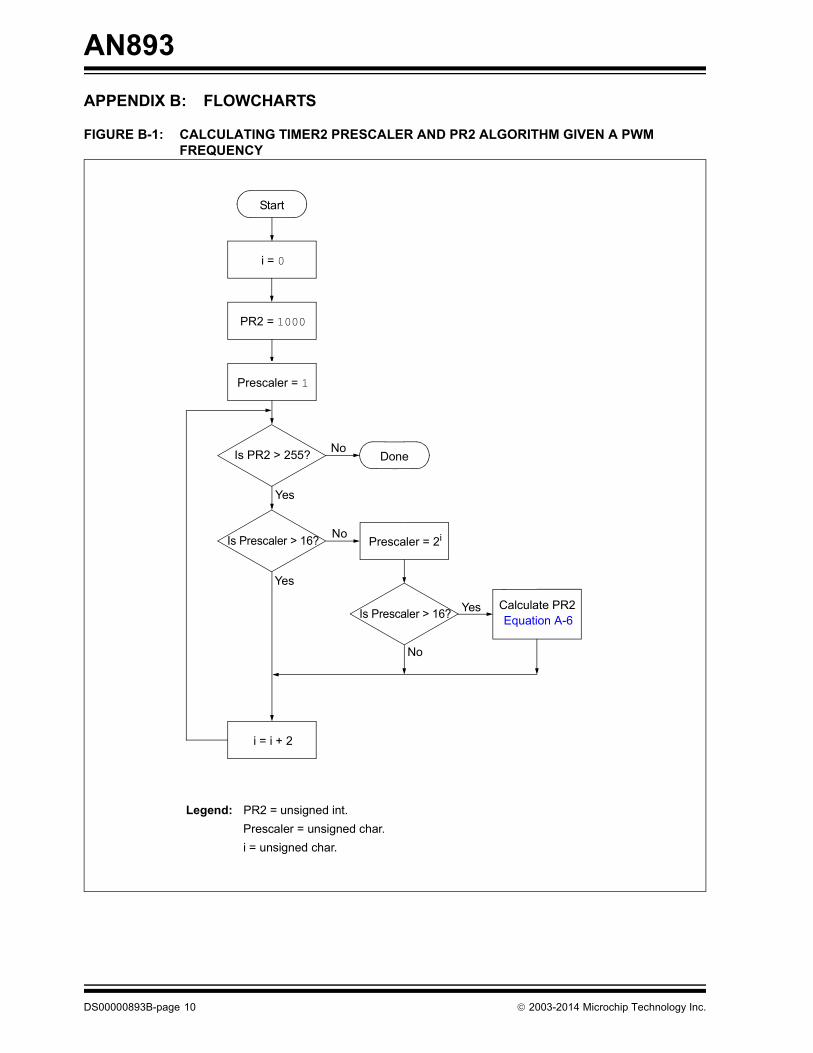
T2CONThe T2CON register is used for setting up the Timer2prescaler and turning on Timer2. The Timer2 prescaleris contained in bits T2CON<1:0> and is used indetermining the PWM frequency, duty cycle andresolution. Timer2 must be turned on by setting bitT2CON<2> before the PWM signal starts. An algorithmthat calculates the Timer2 prescaler and PR2 values forPWM frequencies is shown in Figure B-1.
DS00000893B-page 2 2003-2014 Microchip Technology Inc.
AN893
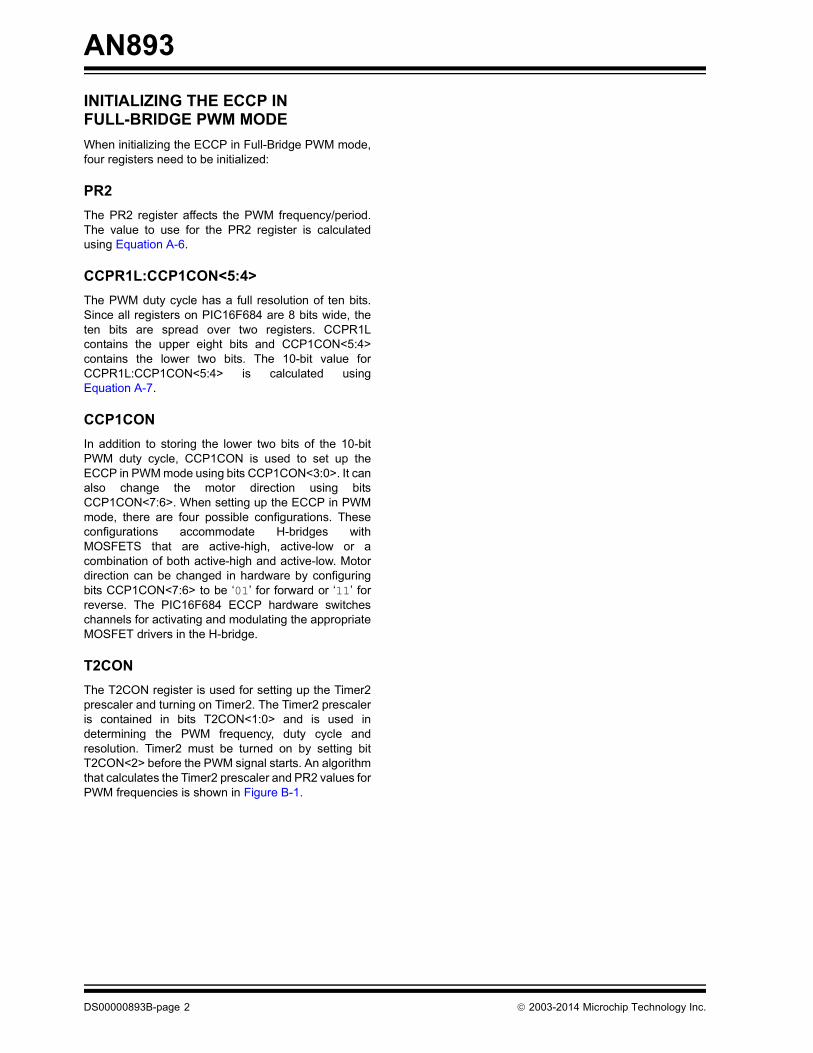
BIDIRECTIONAL BDC MOTOR CONTROLThe ECCP makes changing the motor direction easyby configuring CCP1CON<7:6> to be ‘01’ for forward(Figure 1) or ‘11’ for reverse (Figure 2).
FIGURE 1: FULL-BRIDGE FORWARD CURRENT FLOW DIAGRAM
FIGURE 2: FULL-BRIDGE REVERSE CURRENT FLOW DIAGRAM
P1A
P1C
FETDriver
FETDriver
V+
BDC
FETDriver
FETDriver
P1B
P1D
QA
QB QD
QC
Logic ‘1’
Logic ‘0’
Logic ‘0’
CCP1CON<3:0> = 1100CCP1CON<7:6> = 01
I
PIC16F684
P1A
P1C
FETDriver
FETDriver
V+
FETDriver
FETDriver
P1B
P1D
QA
QB QD
QC
Logic ‘0’
Logic ‘0’
Logic ‘1’
BDC
CCP1CON<3:0> = 1100CCP1CON<7:6> = 11
I
PIC16F684
2003-2014 Microchip Technology Inc. DS00000893B-page 3
AN893
LOW COST SENSORLESS MOTOR CONTROL FEEDBACK
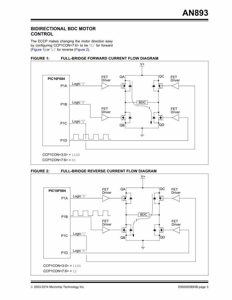
Sensorless RPM MeasurementLow-cost RPM measurement can be performed with aBDC motor by measuring the back EMF voltage fromthe motor (see Figure 3). The BDC RPM is directlyproportional to the back EMF voltage. Since a BDCmotor can be modeled as an inductive load, the voltageacross the motor is equivalent to the inductancemultiplied by dI/dt. In this application, a 12V, 9600 maxRPM BDC motor was used. To measure the back EMFvoltage, turn off the modulated FET. This will cause thecurrent to flow in the opposite direction. After initiallyshutting off the FET, dI/dt must stabilize before takingthe measurement. In order to use the PIC®
microcontroller A/D converter, the measured voltagemust be between 0V and VDD. Since the back EMFvoltage can be between 0V-12V, a voltage dividercircuit is used to scale the back EMF voltage between0V and VDD. Using Microchip’s MSP6S26Programmable Gain Amplifier (PGA), a gain of 1 isused for buffering the scaled voltage that is beingmeasured by the PIC16F684 A/D channel (seeEquation A-8 for calculating RPM).
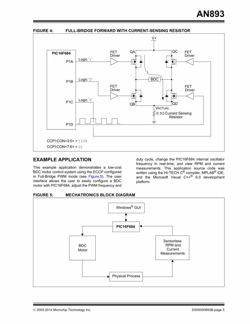
Sensorless Current MeasurementLow-cost current measurements can be performed byusing a current sensing resistor between theMOSFETS and ground (see Figure 4). To select avalue appropriate for the resistance, consider themaximum amount of current allowed to flow throughthe resistor and the maximum amount of powerdissipation.
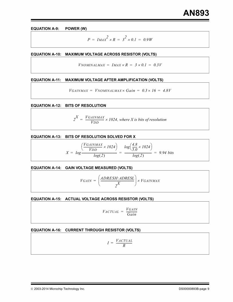
In this application, a 0.1 ohm, 1W current sensingresistor was used with a maximum current of 3A. When3A flow through the resistor, the ideal power dissipatedin the resistor is 0.9W (see Equation A-9) and thevoltage across the resistor is 0.3V (see Equation A-10).In order to get the most resolution from the 10-bit A/Dconverter, the voltage across the resistor at 3A must beamplified as close as possible to the PIC16F684 VDD,which is 5V in this application. Using Microchip’sMSP6S26 PGA, a gain of 16 will ideally give 4.8V, atthe maximum 3A specified current (seeEquation A-11). A gain of 16 gives a 9.94-bit A/Dresolution for measuring current (see Equations A-12and A-13). The current through the resistor can then becomputed using Equations A-14, A-15 and A-16.
Since a PWM signal is used to drive the BDC motor,the H-bridge circuit only draws current during thehigh pulse-width of the PWM period. To obtain acurrent measurement, the voltage across the currentsensing resistor is sampled over a PWM period. Asampling and averaging algorithm of takingmeasurements over multiple PWM periods is shownin Figure B-2.
FIGURE 3: FULL-BRIDGE FORWARD CONFIGURATION WITH BACK EMF MEASUREMENT
P1A
P1C
FETDriver
FETDriver
V+
FETDriver
FETDriver
P1B
P1D
QA
QB QD
QC
Logic ‘1’
Logic ‘0’
Logic ‘0’
BDC
CCP1CON<3:0> = 1100CCP1CON<7:6> = 01
I
Logic ‘0’
VBACKEMF
PIC16F684
DS00000893B-page 4 2003-2014 Microchip Technology Inc.
AN893
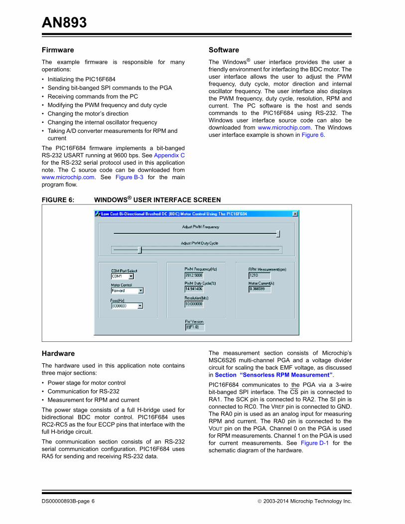
FIGURE 4: FULL-BRIDGE FORWARD WITH CURRENT-SENSING RESISTOREXAMPLE APPLICATIONThis example application demonstrates a low-costBDC motor control system using the ECCP configuredin Full-Bridge PWM mode (see Figure 5). The userinterface allows the user to easily configure a BDCmotor with PIC16F684, adjust the PWM frequency and
duty cycle, change the PIC16F684 internal oscillatorfrequency in real-time, and view RPM and currentmeasurements. This application source code waswritten using the HI-TECH C® compiler, MPLAB® IDE,and the Microsoft Visual C++® 6.0 developmentplatform.
FIGURE 5: MECHATRONICS BLOCK DIAGRAM
P1A
P1C
FETDriver
FETDriver
V+
FETDriver
FETDriver
P1B
P1D
QA
QB QD
QC
Logic ‘1’
Logic ‘0’
Logic ‘0’
BDC
CCP1CON<3:0> = 1100CCP1CON<7:6> = 01
I
0.1VACTUAL
Current SensingResistor
PIC16F684
Windows® GUI
BDCMotor
SensorlessRPM andCurrent
Measurements
Physical Process
PIC16F684
2003-2014 Microchip Technology Inc. DS00000893B-page 5
AN893
FirmwareThe example firmware is responsible for manyoperations:• Initializing the PIC16F684• Sending bit-banged SPI commands to the PGA• Receiving commands from the PC• Modifying the PWM frequency and duty cycle• Changing the motor’s direction• Changing the internal oscillator frequency• Taking A/D converter measurements for RPM and
current
The PIC16F684 firmware implements a bit-bangedRS-232 USART running at 9600 bps. See Appendix Cfor the RS-232 serial protocol used in this applicationnote. The C source code can be downloaded fromwww.microchip.com. See Figure B-3 for the mainprogram flow.
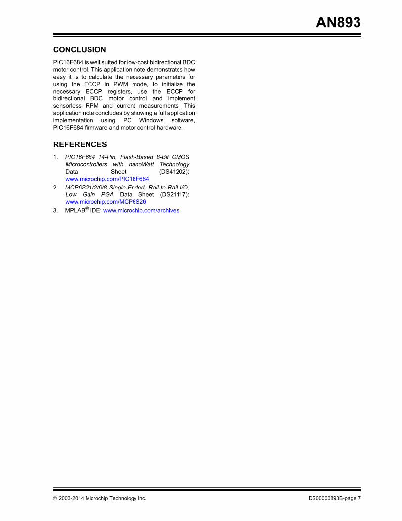
SoftwareThe Windows® user interface provides the user afriendly environment for interfacing the BDC motor. Theuser interface allows the user to adjust the PWMfrequency, duty cycle, motor direction and internaloscillator frequency. The user interface also displaysthe PWM frequency, duty cycle, resolution, RPM andcurrent. The PC software is the host and sendscommands to the PIC16F684 using RS-232. TheWindows user interface source code can also bedownloaded from www.microchip.com. The Windowsuser interface example is shown in Figure 6.
FIGURE 6: WINDOWS® USER INTERFACE SCREEN
HardwareThe hardware used in this application note containsthree major sections:
• Power stage for motor control• Communication for RS-232• Measurement for RPM and current
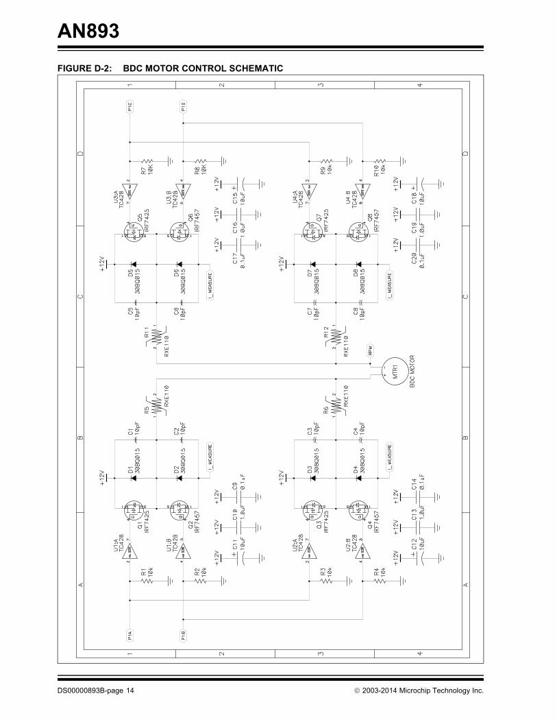
The power stage consists of a full H-bridge used forbidirectional BDC motor control. PIC16F684 usesRC2-RC5 as the four ECCP pins that interface with thefull H-bridge circuit.
The communication section consists of an RS-232serial communication configuration. PIC16F684 usesRA5 for sending and receiving RS-232 data.
The measurement section consists of Microchip’sMSC6S26 multi-channel PGA and a voltage dividercircuit for scaling the back EMF voltage, as discussedin Section “Sensorless RPM Measurement”.
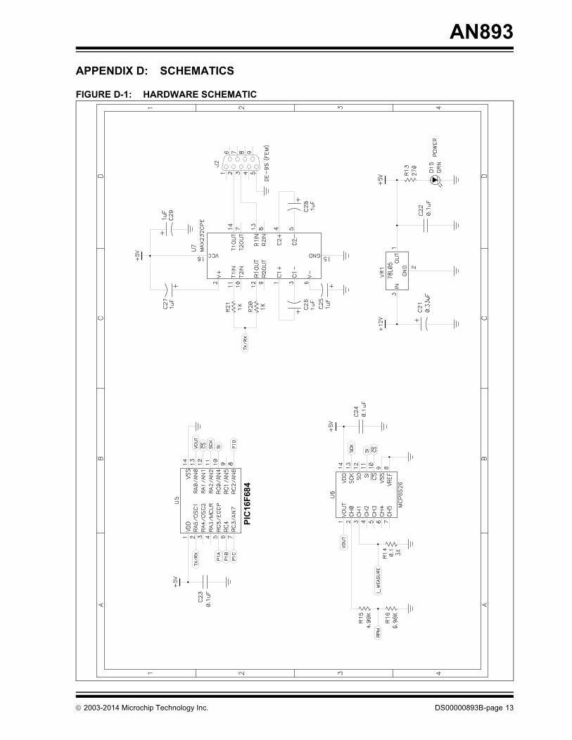
PIC16F684 communicates to the PGA via a 3-wirebit-banged SPI interface. The CS pin is connected toRA1. The SCK pin is connected to RA2. The SI pin isconnected to RC0. The VREF pin is connected to GND.The RA0 pin is used as an analog input for measuringRPM and current. The RA0 pin is connected to theVOUT pin on the PGA. Channel 0 on the PGA is usedfor RPM measurements. Channel 1 on the PGA is usedfor current measurements. See Figure D-1 for theschematic diagram of the hardware.
DS00000893B-page 6 2003-2014 Microchip Technology Inc.
AN893
CONCLUSIONPIC16F684 is well suited for low-cost bidirectional BDCmotor control. This application note demonstrates howeasy it is to calculate the necessary parameters forusing the ECCP in PWM mode, to initialize thenecessary ECCP registers, use the ECCP forbidirectional BDC motor control and implementsensorless RPM and current measurements. Thisapplication note concludes by showing a full applicationimplementation using PC Windows software,PIC16F684 firmware and motor control hardware.
REFERENCES1. PIC16F684 14-Pin, Flash-Based 8-Bit CMOS
Microcontrollers with nanoWatt TechnologyData Sheet (DS41202):www.microchip.com/PIC16F684
2. MCP6S21/2/6/8 Single-Ended, Rail-to-Rail I/O,Low Gain PGA Data Sheet (DS21117):www.microchip.com/MCP6S26
3. MPLAB® IDE: www.microchip.com/archives
2003-2014 Microchip Technology Inc. DS00000893B-page 7

AN893
APPENDIX A:EQUATIONS
EQUATION A-1: PWM FREQUENCY (HZ)
EQUATION A-2: PWM PERIOD (SECONDS)
EQUATION A-3: DUTY CYCLE (SECONDS)
EQUATION A-4: VOLTAGE ACROSS BDC MOTOR (VOLTS)
EQUATION A-5: RESOLUTION (BITS)
EQUATION A-6: PR2
EQUATION A-7: CCPR1L:CCP1CON<5:4>
EQUATION A-8: RPM
Frequency 1Period------------------=
Period PR2 1+ 4 TOSC TMR2Prescaler=
DC CCPR1L:CCP1CON<5:4> TOSC TMR2Prescaler=
VBDC VDDDC
Period------------------ =
Resolution
FOSCFPWM TMR2Prescaler
------------------------------------------------------------------------ log
2 log--------------------------------------------------------------------------------------=
PR2 Period4 TOSC TMR2Prescaler----------------------------------------------------------------------- 1–=
CCPR1L:CCP1CON<5:4> DCTOSC TMR2Prescaler--------------------------------------------------------------=
RPM 1 ADRESH:ADRESL1024------------------------------------------------
– RPMMAX=
DS00000893B-page 8 2003-2014 Microchip Technology Inc.
AN893
EQUATION A-9: POWER (W)EQUATION A-10: MAXIMUM VOLTAGE ACROSS RESISTOR (VOLTS)
EQUATION A-11: MAXIMUM VOLTAGE AFTER AMPLIFICATION (VOLTS)
EQUATION A-12: BITS OF RESOLUTION
EQUATION A-13: BITS OF RESOLUTION SOLVED FOR X
EQUATION A-14: GAIN VOLTAGE MEASURED (VOLTS)
EQUATION A-15: ACTUAL VOLTAGE ACROSS RESISTOR (VOLTS)
EQUATION A-16: CURRENT THROUGH RESISTOR (VOLTS)
P IMAX2 R 32 0.1 0.9W= = =
VNOMINALMAX IMAX R 3 0.1 0.3V= = =
VGAINMAX VNOMINALMAX Gain 0.3 16 4.8V= = =
2X VGAINMAXVDD
--------------------------- 1024 , where X is bits of resolution=
X
VGAINMAXVDD
--------------------------- 1024
2 log---------------------------------------------------log
4.85.0------- 1024 log
2 log--------------------------------------- 9.94 bits= = =
VGAINADRESH:ADRESL
2X------------------------------------------------
VGAINMAX=
VACTUALVGAINGain----------------=
I VACTUALR-----------------------=
2003-2014 Microchip Technology Inc. DS00000893B-page 9
AN893
APPENDIX B: FLOWCHARTS
FIGURE B-1: CALCULATING TIMER2 PRESCALER AND PR2 ALGORITHM GIVEN A PWM FREQUENCY
Start
Is PR2 > 255? No
Yes
No
Yes
Calculate PR2Yes
No
i = 0
PR2 = 1000
Prescaler = 1
Prescaler = 2i
Done
i = i + 2
Legend: PR2 = unsigned int.Prescaler = unsigned char.i = unsigned char.
Equation A-6
Is Prescaler > 16?
Is Prescaler > 16?
DS00000893B-page 10 2003-2014 Microchip Technology Inc.

AN893
FIGURE B-2: PWM SAMPLING ANDAVERAGING ALGORITHMFIGURE B-3: MAIN ROUTINE
Start
Is A/Dconversion
All samplestaken?
ConversionStart A/D
No
Yes
No
Yes
PeriodMeasure PWM
Delay
Log Sample
complete?
Done
SamplesAverage
Increment Delay
PWM High-EdgeSynchronize on
Start
Is command
Send Response
Initialize
valid?
Is commandreceived?
CommandProcess
No
Yes
No
Yes
PIC16F684
2003-2014 Microchip Technology Inc. DS00000893B-page 11
AN893
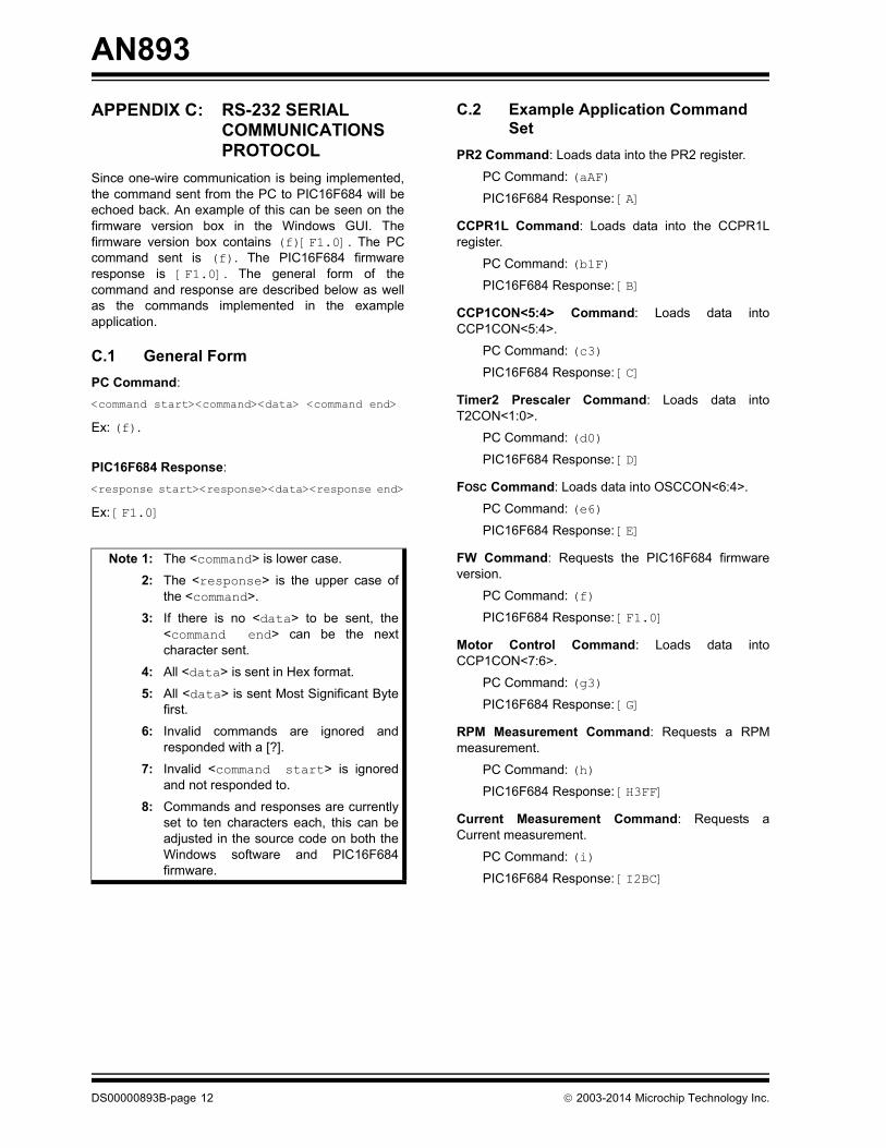
APPENDIX C: RS-232 SERIAL COMMUNICATIONS PROTOCOL
Since one-wire communication is being implemented,the command sent from the PC to PIC16F684 will beechoed back. An example of this can be seen on thefirmware version box in the Windows GUI. Thefirmware version box contains (f)[F1.0]. The PCcommand sent is (f). The PIC16F684 firmwareresponse is [F1.0]. The general form of thecommand and response are described below as wellas the commands implemented in the exampleapplication.
C.1 General FormPC Command:<command start><command><data> <command end>Ex: (f).
PIC16F684 Response:<response start><response><data><response end>Ex: [F1.0]
C.2 Example Application Command Set
PR2 Command: Loads data into the PR2 register.
PC Command: (aAF)PIC16F684 Response: [A]
CCPR1L Command: Loads data into the CCPR1Lregister.
PC Command: (b1F)PIC16F684 Response: [B]
CCP1CON<5:4> Command: Loads data intoCCP1CON<5:4>.
PC Command: (c3)PIC16F684 Response: [C]
Timer2 Prescaler Command: Loads data intoT2CON<1:0>.
PC Command: (d0)PIC16F684 Response: [D]
FOSC Command: Loads data into OSCCON<6:4>.
PC Command: (e6)PIC16F684 Response: [E]
FW Command: Requests the PIC16F684 firmwareversion.
PC Command: (f)PIC16F684 Response: [F1.0]
Motor Control Command: Loads data intoCCP1CON<7:6>.
PC Command: (g3)PIC16F684 Response: [G]
RPM Measurement Command: Requests a RPMmeasurement.
PC Command: (h)PIC16F684 Response: [H3FF]
Current Measurement Command: Requests aCurrent measurement.
PC Command: (i)PIC16F684 Response: [I2BC]
Note 1: The <command> is lower case.
2: The <response> is the upper case ofthe <command>.
3: If there is no <data> to be sent, the<command end> can be the nextcharacter sent.
4: All <data> is sent in Hex format.
5: All <data> is sent Most Significant Bytefirst.
6: Invalid commands are ignored andresponded with a [?].
7: Invalid <command start> is ignoredand not responded to.
8: Commands and responses are currentlyset to ten characters each, this can beadjusted in the source code on both theWindows software and PIC16F684firmware.
DS00000893B-page 12 2003-2014 Microchip Technology Inc.
AN893
APPENDIX D: SCHEMATICS
FIGURE D-1: HARDWARE SCHEMATIC
PIC
16F6
84
2003-2014 Microchip Technology Inc. DS00000893B-page 13
AN893
FIGURE D-2: BDC MOTOR CONTROL SCHEMATICDS00000893B-page 14 2003-2014 Microchip Technology Inc.
Note the following details of the code protection feature on Microchip devices:• Microchip products meet the specification contained in their particular Microchip Data Sheet.
• Microchip believes that its family of products is one of the most secure families of its kind on the market today, when used in the intended manner and under normal conditions.
• There are dishonest and possibly illegal methods used to breach the code protection feature. All of these methods, to our knowledge, require using the Microchip products in a manner outside the operating specifications contained in Microchip’s Data Sheets. Most likely, the person doing so is engaged in theft of intellectual property.
• Microchip is willing to work with the customer who is concerned about the integrity of their code.
• Neither Microchip nor any other semiconductor manufacturer can guarantee the security of their code. Code protection does not mean that we are guaranteeing the product as “unbreakable.”
Code protection is constantly evolving. We at Microchip are committed to continuously improving the code protection features of ourproducts. Attempts to break Microchip’s code protection feature may be a violation of the Digital Millennium Copyright Act. If such actsallow unauthorized access to your software or other copyrighted work, you may have a right to sue for relief under that Act.
Information contained in this publication regarding deviceapplications and the like is provided only for your convenienceand may be superseded by updates. It is your responsibility toensure that your application meets with your specifications.MICROCHIP MAKES NO REPRESENTATIONS ORWARRANTIES OF ANY KIND WHETHER EXPRESS ORIMPLIED, WRITTEN OR ORAL, STATUTORY OROTHERWISE, RELATED TO THE INFORMATION,INCLUDING BUT NOT LIMITED TO ITS CONDITION,QUALITY, PERFORMANCE, MERCHANTABILITY ORFITNESS FOR PURPOSE. Microchip disclaims all liabilityarising from this information and its use. Use of Microchipdevices in life support and/or safety applications is entirely atthe buyer’s risk, and the buyer agrees to defend, indemnify andhold harmless Microchip from any and all damages, claims,suits, or expenses resulting from such use. No licenses areconveyed, implicitly or otherwise, under any Microchipintellectual property rights.
2003-2014 Microchip Technology Inc.
QUALITY MANAGEMENT SYSTEM CERTIFIED BY DNV
== ISO/TS 16949 ==
Trademarks
The Microchip name and logo, the Microchip logo, dsPIC, FlashFlex, KEELOQ, KEELOQ logo, MPLAB, mTouch, PIC, PICmicro, PICSTART, PIC32 logo, rfPIC, SST, SST Logo, SuperFlash and UNI/O are registered trademarks of Microchip Technology Incorporated in the U.S.A. and other countries.
FilterLab, Hampshire, HI-TECH C, Linear Active Thermistor, MTP, SEEVAL and The Embedded Control Solutions Company are registered trademarks of Microchip Technology Incorporated in the U.S.A.
Silicon Storage Technology is a registered trademark of Microchip Technology Inc. in other countries.
Analog-for-the-Digital Age, Application Maestro, BodyCom, chipKIT, chipKIT logo, CodeGuard, dsPICDEM, dsPICDEM.net, dsPICworks, dsSPEAK, ECAN, ECONOMONITOR, FanSense, HI-TIDE, In-Circuit Serial Programming, ICSP, Mindi, MiWi, MPASM, MPF, MPLAB Certified logo, MPLIB, MPLINK, Omniscient Code Generation, PICC, PICC-18, PICDEM, PICDEM.net, PICkit, PICtail, REAL ICE, rfLAB, Select Mode, SQI, Serial Quad I/O, Total Endurance, TSHARC, UniWinDriver, WiperLock, ZENA and Z-Scale are trademarks of Microchip Technology Incorporated in the U.S.A. and other countries.
SQTP is a service mark of Microchip Technology Incorporated in the U.S.A.
GestIC and ULPP are registered trademarks of Microchip Technology Germany II GmbH & Co. KG, a subsidiary of Microchip Technology Inc., in other countries.
All other trademarks mentioned herein are property of their respective companies.
© 2003-2014, Microchip Technology Incorporated, Printed in the U.S.A., All Rights Reserved.
Printed on recycled paper.
ISBN: 978-1-63276-321-1
DS00000893B-page 15
Microchip received ISO/TS-16949:2009 certification for its worldwide headquarters, design and wafer fabrication facilities in Chandler and Tempe, Arizona; Gresham, Oregon and design centers in California and India. The Company’s quality system processes and procedures are for its PIC® MCUs and dsPIC® DSCs, KEELOQ® code hopping devices, Serial EEPROMs, microperipherals, nonvolatile memory and analog products. In addition, Microchip’s quality system for the design and manufacture of development systems is ISO 9001:2000 certified.
DS00000893B-page 16 2003-2014 Microchip Technology Inc.
AMERICASCorporate Office2355 West Chandler Blvd.Chandler, AZ 85224-6199Tel: 480-792-7200 Fax: 480-792-7277Technical Support: http://www.microchip.com/supportWeb Address: www.microchip.comAtlantaDuluth, GA Tel: 678-957-9614 Fax: 678-957-1455Austin, TXTel: 512-257-3370 BostonWestborough, MA Tel: 774-760-0087 Fax: 774-760-0088ChicagoItasca, IL Tel: 630-285-0071 Fax: 630-285-0075ClevelandIndependence, OH Tel: 216-447-0464 Fax: 216-447-0643DallasAddison, TX Tel: 972-818-7423 Fax: 972-818-2924DetroitNovi, MI Tel: 248-848-4000Houston, TX Tel: 281-894-5983IndianapolisNoblesville, IN Tel: 317-773-8323Fax: 317-773-5453Los AngelesMission Viejo, CA Tel: 949-462-9523 Fax: 949-462-9608New York, NY Tel: 631-435-6000San Jose, CA Tel: 408-735-9110Canada - TorontoTel: 905-673-0699 Fax: 905-673-6509
ASIA/PACIFICAsia Pacific OfficeSuites 3707-14, 37th FloorTower 6, The GatewayHarbour City, KowloonHong KongTel: 852-2943-5100Fax: 852-2401-3431Australia - SydneyTel: 61-2-9868-6733Fax: 61-2-9868-6755China - BeijingTel: 86-10-8569-7000 Fax: 86-10-8528-2104China - ChengduTel: 86-28-8665-5511Fax: 86-28-8665-7889China - ChongqingTel: 86-23-8980-9588Fax: 86-23-8980-9500China - HangzhouTel: 86-571-8792-8115 Fax: 86-571-8792-8116China - Hong Kong SARTel: 852-2943-5100 Fax: 852-2401-3431China - NanjingTel: 86-25-8473-2460Fax: 86-25-8473-2470China - QingdaoTel: 86-532-8502-7355Fax: 86-532-8502-7205China - ShanghaiTel: 86-21-5407-5533 Fax: 86-21-5407-5066China - ShenyangTel: 86-24-2334-2829Fax: 86-24-2334-2393China - ShenzhenTel: 86-755-8864-2200 Fax: 86-755-8203-1760China - WuhanTel: 86-27-5980-5300Fax: 86-27-5980-5118China - XianTel: 86-29-8833-7252Fax: 86-29-8833-7256China - XiamenTel: 86-592-2388138 Fax: 86-592-2388130China - ZhuhaiTel: 86-756-3210040 Fax: 86-756-3210049
ASIA/PACIFICIndia - BangaloreTel: 91-80-3090-4444 Fax: 91-80-3090-4123India - New DelhiTel: 91-11-4160-8631Fax: 91-11-4160-8632India - PuneTel: 91-20-3019-1500Japan - OsakaTel: 81-6-6152-7160 Fax: 81-6-6152-9310Japan - TokyoTel: 81-3-6880- 3770 Fax: 81-3-6880-3771Korea - DaeguTel: 82-53-744-4301Fax: 82-53-744-4302Korea - SeoulTel: 82-2-554-7200Fax: 82-2-558-5932 or 82-2-558-5934Malaysia - Kuala LumpurTel: 60-3-6201-9857Fax: 60-3-6201-9859Malaysia - PenangTel: 60-4-227-8870Fax: 60-4-227-4068Philippines - ManilaTel: 63-2-634-9065Fax: 63-2-634-9069SingaporeTel: 65-6334-8870Fax: 65-6334-8850Taiwan - Hsin ChuTel: 886-3-5778-366Fax: 886-3-5770-955Taiwan - KaohsiungTel: 886-7-213-7830Taiwan - TaipeiTel: 886-2-2508-8600 Fax: 886-2-2508-0102Thailand - BangkokTel: 66-2-694-1351Fax: 66-2-694-1350
EUROPEAustria - WelsTel: 43-7242-2244-39Fax: 43-7242-2244-393Denmark - CopenhagenTel: 45-4450-2828 Fax: 45-4485-2829France - ParisTel: 33-1-69-53-63-20 Fax: 33-1-69-30-90-79Germany - DusseldorfTel: 49-2129-3766400Germany - MunichTel: 49-89-627-144-0 Fax: 49-89-627-144-44Germany - PforzheimTel: 49-7231-424750Italy - Milan Tel: 39-0331-742611 Fax: 39-0331-466781Italy - VeniceTel: 39-049-7625286 Netherlands - DrunenTel: 31-416-690399 Fax: 31-416-690340Poland - WarsawTel: 48-22-3325737 Spain - MadridTel: 34-91-708-08-90Fax: 34-91-708-08-91Sweden - StockholmTel: 46-8-5090-4654UK - WokinghamTel: 44-118-921-5800Fax: 44-118-921-5820
Worldwide Sales and Service
03/25/14