analog devices welcomes hittite microwave corporation · analog devices welcomes hittite microwave...
TRANSCRIPT

Analog Devices Welcomes Hittite Microwave Corporation
NO CONTENT ON THE ATTACHED DOCUMENT HAS CHANGED
www.analog.com www.hittite.com

THIS PAGE INTENTIONALLY LEFT BLANK

Serial/Parallel USB Interface Kit
HMC-DK008
HMC-DK008126943 E - 03.0714
CP140301
User ManualInstallation & Operation Guide
Analog & Mixed-Signal ICs, Modules, Subsystems & Instrumentation
20 Alpha Road Chelmsford, MA 01824Phone: 978-250-3343 • Fax: 978-250-3373 • [email protected]
Order On-Line at: www.hittite.com Receive the latest product releases - click on “My Subscription”

2
Rev E - 03.0714
Order On-Line: www.hittite.com. For technical application questions: Phone: 978-250-3343 or [email protected]
HMC-DK008 Serial/Parallel USB Interface Kit User Manual
What We Do
Hittite Microwave Corporation is an innovative designer and manufacturer of analog, digital, mixed-signal ICs, modules, subsystems and instrumentation for RF, microwave and millimeterwave applications covering DC to 110 GHz. Our RFIC/MMIC products are developed using state-of-the-art GaAs, GaN, InGaP/GaAs, InP, SOI, SiGe, CMOS and BiCMOS semiconductor processes utilizing MESFET, HEMT, pHEMT, mHEMT, HBT and PIN devices. We offer over 850 products across 28 product lines:
We also design and supply highly integrated custom ICs, modules, subsystems and instrumentation that combine multiple functions for specific requirements. We select the most appropriate semiconductor and package technologies, uniquely balancing digital and analog integration techniques.
Our custom and standard products support a wide range of wireless / wired communi-cations and radar applications for the following markets:
Every component is backed by Hittite Microwave’s commitment to total quality. HMC is ISO 9001:2000, AS9100 B and ISO/TS 16949:2002 certified. Every Hittite employee and subcontractor is responsible for maintaining the highest level of quality. We are constantly working towards improvement of our procedures and processes, thus providing our customers with products that meet or exceed all requirements, are delivered on-time and function reliably throughout their useful life.
Automotive
Telematics & Sensors
Broadband
CATV, DBS, WiBro,WiMAX, WLAN, Fixed Wireless & UWB
Cellular Infrastructure
GSM, GPRS, CDMA, WCDMA, UMTS, TD-SCDMA & 4G/LTE
Fiber Optic
OC-48 to 100G
Microwave & mmWave CommunicationsBackhaul Radio LinksMulti-Pt Radios & VSAT
Military
C3I, ECM & EW
Space
Payload Electronics
Test & Measurement
Commercial / Industrial Sensors & Test Equipment
Amplifiers Mixers
Attenuators Mods & Demodulators
Broadband Time Delays Mux & Demux
Comparators Passives
Data Converters Phase Shifters
DC Power Conditioning PLLs
DC Power Management PLLs w/ Integrated VCOs
DROs Power Detectors
Filters - Tunable Sensors
Freq. Dividers & Detectors Signal Generators
Freq. Multipliers Switches
High Speed Digital Logic Transimpedance Amplifiers
Limiting Amplifiers VGAs
Interface VCOs & PLOs

3
Rev E - 03.0714
Order On-Line: www.hittite.com. For technical application questions: Phone: 978-250-3343 or [email protected]
HMC-DK008 Serial/Parallel USB Interface Kit User Manual
NoticeHittite Microwave Corporation has prepared this manual for use by Hittite personnel and customers as a
guide for the proper installation, operation, and maintenance of Hittite equipment and computer programs.
The drawings, specifications, and information contained herein are the property of Hittite Microwave Corpora-
tion, and any unauthorized use or disclosure of these drawings, specifications, and information is prohibited;
they shall not be reproduced, copied, or used in whole or in part as the basis for manufacture or sale of the
equipment or software programs without the prior written consent of Hittite Microwave Corporation.
Table of Contents
1. Introduction. . . . . . . . . . . . . . . . . . . . . . . . . . . . . . . . . . . . . . . . . . . . . . . . . . . . . . . . . . . . . . . . . . . . . . . . . . . .4
2. Package Contents. . . . . . . . . . . . . . . . . . . . . . . . . . . . . . . . . . . . . . . . . . . . . . . . . . . . . . . . . . . . . . . . . . . . . . .4
3. Compatible HMC Products . . . . . . . . . . . . . . . . . . . . . . . . . . . . . . . . . . . . . . . . . . . . . . . . . . . . . . . . . . . . . . .4
4. Operating Environment . . . . . . . . . . . . . . . . . . . . . . . . . . . . . . . . . . . . . . . . . . . . . . . . . . . . . . . . . . . . . . . . . .4
5. Setup and Installation . . . . . . . . . . . . . . . . . . . . . . . . . . . . . . . . . . . . . . . . . . . . . . . . . . . . . . . . . . . . . . . . . . .5
5.1 User Provided Equipment . . . . . . . . . . . . . . . . . . . . . . . . . . . . . . . . . . . . . . . . . . . . . . . . . . . . . . . . . . . . .5
5.2 Driver Installation . . . . . . . . . . . . . . . . . . . . . . . . . . . . . . . . . . . . . . . . . . . . . . . . . . . . . . . . . . . . . . . . . . . .5
5.3 Hardware Setup . . . . . . . . . . . . . . . . . . . . . . . . . . . . . . . . . . . . . . . . . . . . . . . . . . . . . . . . . . . . . . . . . . . . .5
5.4 Software Installation . . . . . . . . . . . . . . . . . . . . . . . . . . . . . . . . . . . . . . . . . . . . . . . . . . . . . . . . . . . . . . . . .8
5.5 Software Usage . . . . . . . . . . . . . . . . . . . . . . . . . . . . . . . . . . . . . . . . . . . . . . . . . . . . . . . . . . . . . . . . . . . . 13
6. Digital Controller GUI Usage . . . . . . . . . . . . . . . . . . . . . . . . . . . . . . . . . . . . . . . . . . . . . . . . . . . . . . . . . . . . .13
6.1 Connecting to HMC Product . . . . . . . . . . . . . . . . . . . . . . . . . . . . . . . . . . . . . . . . . . . . . . . . . . . . . . . . . . 13
6.2 Basic Control . . . . . . . . . . . . . . . . . . . . . . . . . . . . . . . . . . . . . . . . . . . . . . . . . . . . . . . . . . . . . . . . . . . . . . 14
6.2.1 Serial Communication . . . . . . . . . . . . . . . . . . . . . . . . . . . . . . . . . . . . . . . . . . . . . . . . . . . . . . . . 14
6.2.2 Parallel Communication . . . . . . . . . . . . . . . . . . . . . . . . . . . . . . . . . . . . . . . . . . . . . . . . . . . . . . . 14
6.3 Manual Mode . . . . . . . . . . . . . . . . . . . . . . . . . . . . . . . . . . . . . . . . . . . . . . . . . . . . . . . . . . . . . . . . . . . . . . 15
6.3.1 Clock, Serial, Reset and Latch Operations . . . . . . . . . . . . . . . . . . . . . . . . . . . . . . . . . . . . . . . . 15
6.3.2 Bit Value Table . . . . . . . . . . . . . . . . . . . . . . . . . . . . . . . . . . . . . . . . . . . . . . . . . . . . . . . . . . . . . . 15
6.3.3 Parallel/Serial Pin . . . . . . . . . . . . . . . . . . . . . . . . . . . . . . . . . . . . . . . . . . . . . . . . . . . . . . . . . . . . 16
6.3.4 Parallel Active. . . . . . . . . . . . . . . . . . . . . . . . . . . . . . . . . . . . . . . . . . . . . . . . . . . . . . . . . . . . . . . 16
6.3.5 Bit Order. . . . . . . . . . . . . . . . . . . . . . . . . . . . . . . . . . . . . . . . . . . . . . . . . . . . . . . . . . . . . . . . . . . 16
6.3.6 Latch Cycle . . . . . . . . . . . . . . . . . . . . . . . . . . . . . . . . . . . . . . . . . . . . . . . . . . . . . . . . . . . . . . . . 16
6.3.7 Number of Serial Bits . . . . . . . . . . . . . . . . . . . . . . . . . . . . . . . . . . . . . . . . . . . . . . . . . . . . . . . . . 16
6.3.8 Number of Clock Cycles. . . . . . . . . . . . . . . . . . . . . . . . . . . . . . . . . . . . . . . . . . . . . . . . . . . . . . . 17
6.4 Ending Communication . . . . . . . . . . . . . . . . . . . . . . . . . . . . . . . . . . . . . . . . . . . . . . . . . . . . . . . . . . . . . . 17
7. Technical Support. . . . . . . . . . . . . . . . . . . . . . . . . . . . . . . . . . . . . . . . . . . . . . . . . . . . . . . . . . . . . . . . . . . . . . 17

4
Rev E - 03.0714
Order On-Line: www.hittite.com. For technical application questions: Phone: 978-250-3343 or [email protected]
HMC-DK008 Serial/Parallel USB Interface Kit User Manual
1. Introduction
This document describes the usage and functionality of the HMC-DK008 Serial/Parallel USB Interface (SPUI). The HMC-DK008 Serial / Parallel USB Interface Designer’s Kit enables users to interface with Hittite’s family of digital attenuators, interface driver and variable gain amplifiers. This kit includes PC compatible software that generates a Graphical User Interface (GUI) allowing the user to:
• Settheattenuation/gainstateoftheHMCattenuator/amplifier
• Observetheserialdata,clock,latch&resetsignalssenttotheHMCdevice
• Switchbetweenserialandparallelcontrolmodes
• Monitorandcontrolactivebitsinparallelmode
• ConstructcustomserialsignalstosendtotheHMCdevice
The HMC product to be communicated with must be mounted on its evaluation board. Only one HMC product can connect to the SPUI at a time.
2. Package Contents
Verify that all the items listed in Table 1 are included in the shipment.
Item Quantity
HMC-DK008 Serial/Parallel USB Interface Board 1
12” 18 Pin Flat Ribbon Cable 1
6’ USB A Male to USB B Male Cable 1
CD ROM (Contains User Manual and software) 1
Table 1: Packing List
3. Compatible HMC Products
Visit www.hittite.com and check the HMC-DK008’s information page for the most current list of HMC products that are compatible with the SPUI.
4. Operating Environment
The SPUI is designed for use in a laboratory setting at ambient room temperature (25°C) and is not protected against moisture. The SPUI has an electrostatic discharge (ESD) rating of +/-3000V, however the HMC product interfacing with the device may have a lower rating (check the product’s datasheet for its specific ESD rating). Use appropriate ESD procedures and precautionary measures when handling all electronic hardware.

5
Rev E - 03.0714
Order On-Line: www.hittite.com. For technical application questions: Phone: 978-250-3343 or [email protected]
HMC-DK008 Serial/Parallel USB Interface Kit User Manual
5. Setup and Installation
5.1 User Provided Equipment
In addition to the items provided in the HMC-DK008, the user must provide the following equipment to communicate with HMC products.
• DCPowerSupply
• DCcables
• Computer(PC)with •Internetconnection •StandardUSBport •OperatingsystemofWindows2000,XPorVista
5.2 Driver Installation
Before running the SPUI software for the first time, install all necessary hardware drivers.
1. Go to the following website: http://www.ftdichip.com/Drivers/D2XX.htm. Choose the latest driver version for Windows.
2. The pop-up box in Figure 1 should appear to the screen. Click Save.
Figure 1. File Download Pop-up Screen.
When prompted, specify the location to which to save the zip folder for driver installation.
3. Open the downloaded zip folder. Save (extract) the folder inside by dragging it to a known location on the PC.
5.3 Hardware Setup
Connect all hardware according to Figure 2.
1. Connect the desired HMC product’s evaluation board to the SPUI board through the ribbon cable provided in the kit. Ensure that pin1 of the evaluation board connects to pin1 of the SPUI board through pin1 of the ribbon cable.

6
Rev E - 03.0714
Order On-Line: www.hittite.com. For technical application questions: Phone: 978-250-3343 or [email protected]
HMC-DK008 Serial/Parallel USB Interface Kit User Manual
i. Pin1 of the evaluation board is the Latch pin
ii. Pin1 of the SPUI board is marked with a white dot (also the Latch pin)
iii. Pin1 of the ribbon cable is marked with a red line
Evaluation PCB
RIBBON CABLE
Serial/ParallelUSB Interface(SPUI Board)
USB Interface
Header
Hea
der
HMCPart
PowerSupply*
USB CABLE
DC CABLES*
* DEVICE MUST BE PROVIDED BY THE USER.
PC*DC Pins
Figure 2: HMC-DK008 Block Diagram
2. Connect the SPUI to the USB port of the desired PC’s CPU through the USB cable provided in the kit. The PC should then detect new hardware called DLP2232M.
3. The Found New Hardware Wizard in Figure 3 should appear. Click the radio button next to the “No, only this time” option. Click Next.
Figure 3. Hardware Wizard Screen 1.

7
Rev E - 03.0714
Order On-Line: www.hittite.com. For technical application questions: Phone: 978-250-3343 or [email protected]
HMC-DK008 Serial/Parallel USB Interface Kit User Manual
4. The screen in Figure 4 will appear. Click the radio button to select the “Install from a list or specific location” option. Click Next.
Figure 4. Hardware Wizard Screen 2.
5. The screen in Figure 5 will appear. Browse to the location of the files extracted from the zip folder (see Step 3 of section 5.2). Click Next.
Figure 5. Hardware Wizard Screen 3.
8
Rev E - 03.0714
Order On-Line: www.hittite.com. For technical application questions: Phone: 978-250-3343 or [email protected]
HMC-DK008 Serial/Parallel USB Interface Kit User Manual
6. The screen in Figure 6 will appear. Click Finish.
Figure 6. Hardware Wizard Screen 4.
5.4 Software Installation
Install the SPUI software by following the instructions in this section.
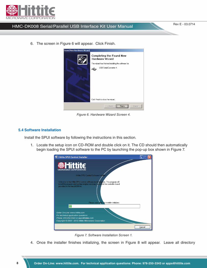
1. Locate the setup icon on CD-ROM and double click on it. The CD should then automatically begin loading the SPUI software to the PC by launching the pop-up box shown in Figure 7.
Figure 7. Software Installation Screen 1.
4. Once the installer finishes initializing, the screen in Figure 8 will appear. Leave all directory

9
Rev E - 03.0714
Order On-Line: www.hittite.com. For technical application questions: Phone: 978-250-3343 or [email protected]
HMC-DK008 Serial/Parallel USB Interface Kit User Manual
locations as the default locations (unless otherwise desired). Click Next.
Figure 8. Software Installation Screen 2.
5. The screen in Figure 9 will appear. Read though the Hittite Microwave Corporation licensing agreement and click the “I accept the License Agreement” to accept. Then click Next.
Figure 9. Hittite Microwave Corporation License Agreement.
6. The screen in Figure 10 will appear. Read through the National Instruments licensing agreement and select the radio button next to the “I accept the License Agreement” to accept. Then click Next.

10
Rev E - 03.0714
Order On-Line: www.hittite.com. For technical application questions: Phone: 978-250-3343 or [email protected]
HMC-DK008 Serial/Parallel USB Interface Kit User Manual
Figure 10. National Instruments License Agreement.
7. The screen in Figure 11 will appear. Click Next to begin installation.
Figure 11. Software Installation Screen 1.
8. Figure 12 will appear as software begins installing on the PC.

11
Rev E - 03.0714
Order On-Line: www.hittite.com. For technical application questions: Phone: 978-250-3343 or [email protected]
HMC-DK008 Serial/Parallel USB Interface Kit User Manual
Figure 12. Software Installation Screen 2.
9. When the software is done installing on the PC, the screen in Figure 13 will appear. Click Finish to complete software installation.
Figure 13. Software Installation Finish Screen.
10. It is recommended to click Restart per Figure 14. This will reboot your computer and complete the software installation.

12
Rev E - 03.0714
Order On-Line: www.hittite.com. For technical application questions: Phone: 978-250-3343 or [email protected]
HMC-DK008 Serial/Parallel USB Interface Kit User Manual
Figure 14. Recommended Restart Screen.
5.5 Software Usage
Click the Windows Start button. Locate the SPUI Control Software (in the Programs menu) and click the HMC SPUI Control icon. The GUI shown in Figure 15 should appear to the screen.
Figure 15. GUI Display.
6. Digital Controller GUI Usage
Before initiating communication, ensure that the software program is the most current version. Check the revision of your software (found in the About tab) and compare it with the most current revision listed on the HMC-DK008 information page on the Hittite Microwave website (www.hittite.com). If there is a more recent version available, contact the Applications group to receive the latest SPUI software.
If your evaluation board has DIP switches, they will be disabled once the ribbon cable has been connected to the board. These switches cannot be used to control the HMC part while the HMC-DK008 is in use.
6.1 Connecting to HMC Product
1. Click the Connect button on the GUI screen. Once a connection has been established the button will turn green and change to say “Connected”.
2. Select the HMC product the be controlled from the “Part Number” drop down menu.
6.2 Basic Control
6.2.1 Serial Communication
All HMC products that are compatible with the SPUI can communicate serially. To send serial data to the HMC product, keep the Serial setting in the “Data Input Type” drop down box.

13
Rev E - 03.0714
Order On-Line: www.hittite.com. For technical application questions: Phone: 978-250-3343 or [email protected]
HMC-DK008 Serial/Parallel USB Interface Kit User Manual
Enter the desired attenuation level in the “Attenuation State” field.
Note: If the HMC product does not support the entered attenuation state, the SPUI will automatically round the entered value to the closest valid attenuation state.
6.2.2 Parallel Communication
If the selected HMC product is capable of parallel communication, a Parallel option will be available. To send parallel data to the HMC product, select this option. The screen in Figure 16 will appear.
Figure 16. Parallel Communication Screen.
The desired attenuation level can be entered in two ways:
1. Type the attenuation value into the “Attenuation Value” field. The LEDs corresponding to the active bits required for the entered state will illuminate.
2. Click the LEDs corresponding to the bits required to achieve the desired attenuation level (LEDs should illuminate upon activating). The value in the “Attenuation Value” field will adjust to reflect the current level.
6.3 Manual Mode
Manual Mode can be used to access advanced signal communication options. This mode allows us-ers to build their own digital word. If an HMC product is selected from the Part Number drop-down box before enabling advanced mode, the controls will retain the default values corresponding to the cho-sen product. If no product is selected beforehand, the fields are populated with the values shown in Figure 17.
Figure 17. Default Manual Mode Display

14
Rev E - 03.0714
Order On-Line: www.hittite.com. For technical application questions: Phone: 978-250-3343 or [email protected]
HMC-DK008 Serial/Parallel USB Interface Kit User Manual
To operate in Manual Mode, select the Mode menu at the top of the program and select Advanced. The warning message in Figure 18 will appear.
Figure 18. Manual Mode warning message.
6.3.1 Clock, Serial, Reset and Latch Operations
Depending on the HMC product selected, either the Enable Reset, Enable Latch B, Enable P/S Pin and/or the Enable Bit Order Pin may be enabled. Click the button to enable to corresponding signal if desired. To toggle the Clock, Serial, Reset or Latch signals, click their corresponding buttons. All values are updated real-time and displayed on the serial graph if in serial mode.
6.3.2 Bit Value Table
The Bit Value Table is based off the selected HMC product’s truth table (found in its datasheet). If no HMC part is selected, the Truth Table is populated with the default values shown in Figure 17.
Changing the values in the Bit Value Table will alter the values associated with the input bits to the HMC part. For example, entering X into the first row of the Bit Value Table in Figure 17 will change the definition of the least significant bit from .5 to X. When Latch B is enabled, the first half of the bits in the table are associated with Latch A and the second half are associated with Latch B.
6.3.3 Parallel/Serial Pin
The Serial button is only enabled if the selected HMC product has a Serial/Parallel pin. This button controls how the Parallel/Serial pin is defined (the default value is disabled).
6.3.4 Parallel
The Parallel button is toggled to indicate if the bits to be sent to the HMC product are active high or active low.
6.3.5 Bit Order
The Bit Order button is only enabled if the selected HMC product has a bit order pin. This button controls how the bit order pin is defined (the default value is disabled).
6.3.6 Latch Cycle
If the HMC product to be controlled has a Reset Enable signal, the default latch cycle = # serial bits +1. Otherwise, the default latch cycle = #serial bits. The Latch cycle should never exceed the number of clock cycles. Changing the latch cycle value to less than the HMC product’s default value truncates the Serial Input signal (data beyond the entered latch cycle is lost). Alternately, changing the latch cycle

15
Rev E - 03.0714
Order On-Line: www.hittite.com. For technical application questions: Phone: 978-250-3343 or [email protected]
HMC-DK008 Serial/Parallel USB Interface Kit User Manual
to more than the HMC product’s default value will result in the product not latching and no data will be transferred to the HMC product.
6.3.7 Number of Serial Bits
The number of serial bits is specific to the HMC product. This value can be found on the top right corner of the datasheet as shown in Figure 19. Increasing and reducing the number of serial bits has the same effects as altering the latch cycle (see Section 6.3.6).
Figure 19. Serial Bits on Datasheet.
6.3.8 Number of Clock Cycles
The default number of clock cycles = #serial bits+1. Altering this number changes how many clock cycles appear in the Data tab’s digital graph. A clock cycle is defined as one maximum and one minimum.
6.4 Ending Communication
Click the Quit button in the Data tab to disconnect from the HMC product and exit the SPUI Control program. The GUI will close, ending the communication session.
7. Technical Support
Please contact [email protected] for any questions. Hittite Microwave provides local direct support in many areas around the world. Please see the “Contact Us” page at www.hittite.com.

16
Rev E - 03.0714
Order On-Line: www.hittite.com. For technical application questions: Phone: 978-250-3343 or [email protected]
HMC-DK008 Serial/Parallel USB Interface Kit User Manual

17
Rev E - 03.0714
Order On-Line: www.hittite.com. For technical application questions: Phone: 978-250-3343 or [email protected]
HMC-DK008 Serial/Parallel USB Interface Kit User Manual

20 Alpha Road Chelmsford, MA 01824Phone: 978-250-3343 • Fax: 978-250-3373 • [email protected]
Order On-Line at: www.hittite.com Receive the latest product releases - click on “My Subscription”