analog-digital multimeters t r le metra 12s 18s, 14a … multimeters metra 12s ... 18s, 14a...
TRANSCRIPT
Analog-digital multimetersMETRA 12S ... 18S, 14A
GOSSEN-METRAWATT 1
CAMILL
E BAUER
MET
RAW
ATT
GOSSEN
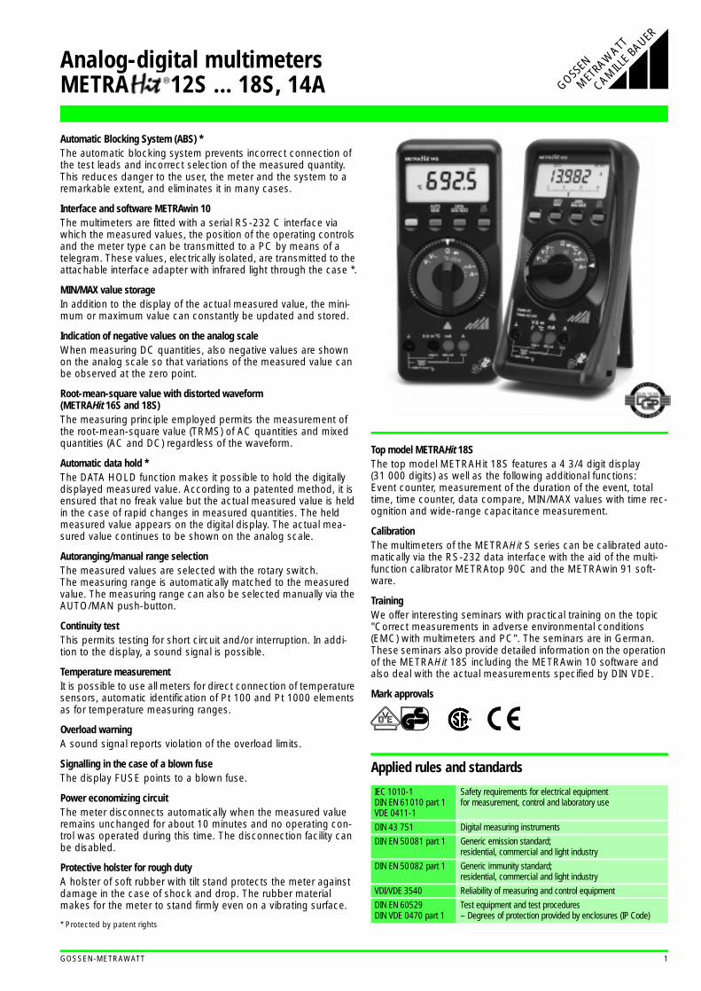
Automatic Blocking System (ABS) *The automatic blocking system prevents incorrect connection of the test leads and incorrect selection of the measured quantity. This reduces danger to the user, the meter and the system to a remarkable extent, and eliminates it in many cases.
Interface and software METRAwin 10The multimeters are fitted with a serial RS-232 C interface via which the measured values, the position of the operating controls and the meter type can be transmitted to a PC by means of a telegram. These values, electrically isolated, are transmitted to the attachable interface adapter with infrared light through the case *.
MIN/MAX value storageIn addition to the display of the actual measured value, the mini-mum or maximum value can constantly be updated and stored.
Indication of negative values on the analog scaleWhen measuring DC quantities, also negative values are shown on the analog scale so that variations of the measured value can be observed at the zero point.
Root-mean-square value with distorted waveform (METRAHit 16S and 18S)The measuring principle employed permits the measurement of the root-mean-square value (TRMS) of AC quantities and mixed quantities (AC and DC) regardless of the waveform.
Automatic data hold *The DATA HOLD function makes it possible to hold the digitally displayed measured value. According to a patented method, it is ensured that no freak value but the actual measured value is held in the case of rapid changes in measured quantities. The held measured value appears on the digital display. The actual mea-sured value continues to be shown on the analog scale.
Autoranging/manual range selectionThe measured values are selected with the rotary switch.The measuring range is automatically matched to the measured value. The measuring range can also be selected manually via the AUTO/MAN push-button.
Continuity testThis permits testing for short circuit and/or interruption. In addi-tion to the display, a sound signal is possible.
Temperature measurementIt is possible to use all meters for direct connection of temperature sensors, automatic identification of Pt 100 and Pt 1000 elements as for temperature measuring ranges.
Overload warningA sound signal reports violation of the overload limits.
Signalling in the case of a blown fuseThe display FUSE points to a blown fuse.
Power economizing circuitThe meter disconnects automatically when the measured value remains unchanged for about 10 minutes and no operating con-trol was operated during this time. The disconnection facility can be disabled.
Protective holster for rough dutyA holster of soft rubber with tilt stand protects the meter against damage in the case of shock and drop. The rubber material makes for the meter to stand firmly even on a vibrating surface.
* Protected by patent rights
Top model METRAHit 18SThe top model METRAHit 18S features a 4 3/4 digit display (31 000 digits) as well as the following additional functions:Event counter, measurement of the duration of the event, total time, time counter, data compare, MIN/MAX values with time rec-ognition and wide-range capacitance measurement.
CalibrationThe multimeters of the METRAHit S series can be calibrated auto-matically via the RS-232 data interface with the aid of the multi-function calibrator METRAtop 90C and the METRAwin 91 soft-ware.
TrainingWe offer interesting seminars with practical training on the topic "Correct measurements in adverse environmental conditions (EMC) with multimeters and PC". The seminars are in German. These seminars also provide detailed information on the operation of the METRAHit 18S including the METRAwin 10 software and also deal with the actual measurements specified by DIN VDE.
Mark approvals
Applied rules and standards
IEC 1010-1DIN EN 61010 part 1VDE 0411-1
Safety requirements for electrical equipment for measurement, control and laboratory use
DIN 43 751 Digital measuring instruments
DIN EN 50081 part 1 Generic emission standard; residential, commercial and light industry
DIN EN 50082 part 1 Generic immunity standard; residential, commercial and light industry
VDI/VDE 3540 Reliability of measuring and control equipment
DIN EN 60529DIN VDE 0470 part 1
Test equipment and test procedures– Degrees of protection provided by enclosures (IP Code)

2 GOSSEN-METRAWATT
Specifications METRAHit 12S ... 16S, 14A
1) TRMS measurement
2) Direct display with clip-on transformer 1000:1
4) At 0 °C ... + 40 °C
5) With zero setting; w/o zero setting + 35 digits
6) With zero setting; w/o zero setting + 50 digits7) METRAHit 13S (w/o 16 A fuse!): 16 A cont., 20 A for 5 min;
METRAHit 14A, 14S ... 16S: 12 A for 5 min, 16 A 30 s
8) Range 3 V : UE = 1.5 Vrms . . . 100 Vrms30 V : UE = 15 Vrms . . . 300 Vrms300 V : UE = 150 Vrms . . . 1000 Vrms
9) On the range 3V , rectangular signal positive at one end 5 ... 15 V, f = const., not 163.84 Hz or integer multiple.
10) Without sensor
Meas. function
Measuring range Resolution Input impedanceInherent deviation of the digital display
±(...% of meas. val. +... digits) for reference conditions Overload capacity 4) Measuring
function
Overload value
Overload duration
METRAHit 12S 13S 14A 14S 15S 16S 12S 13S/14A 14S 15S 16S
V
30.00 mV 10 µV >10 GΩ // < 40 pF 0.5 + 3 5) 0.5 + 3 5)
1200 V
DC
ACeffective
sinusoidal
cont.
V
300.0 mV 100 µV >10 GΩ // < 40 pF 0.5 + 3 0.5 + 3
3.000 V 1 mV 11 MΩ // < 40 pF 0.25 + 1 0.1 + 1
30.00 V 10 mV 10 MΩ // < 40 pF 0.25 + 1 0.1 + 1
300.0 V 100 mV 10 MΩ // < 40 pF 0.25 + 1 0.1 + 11000 V 1 V 10 MΩ // < 40 pF 0.35 + 1 0.1 + 1
V3.000 V 1) 1 mV 11 MΩ // < 40 pF
0.75 + 2 (10 ... 300 D)
0.75 + 1 (> 300 D)0.75 + 3(> 10 D)
V30.00 V 1) 10 mV 10 MΩ // < 40 pF
300.0 V 1) 100 mV 10 MΩ // < 40 pF
1000 V 1) 1 V 10 MΩ // < 40 pF
V3.000 V 1) 1 mV 11 MΩ // < 40 pF — — — —
0,75 + 3(> 10 D)
V30.00 V 1) 10 mV 10 MΩ // < 40 pF — — — —
300.0 V 1) 100 mV 10 MΩ // < 40 pF — — — —
1000 V 1) 1 V 10 MΩ // < 40 pF — — — —
Voltage drop, approx.
12S 13S /14A14S /
15S/16S
A
300.0 µA 100 nA — — 15 mV — — 1.0 + 5 (> 10 D) 0.5 + 5 (> 10 D)
0.36 A cont.
A3.000 mA 1 µA 15 mV 15 mV 150 mV 1.0 + 5 (> 10 D) 1,0 + 2 0.5 + 2
30.00 mA 10 µA 150 mV 150 mV 650 mV 0.25 + 2 1.0 + 5 (> 10 D) 0.5 + 5 (> 10 D)300.0 mA 100 µA 1 V 1 V 1 V 1.0 + 2 0,5 + 2
3.000 A 1 mA — 100 mV 100 mV — 1.0 + 5 (> 10 D) 1.0 + 5 (> 10 D)7) 7)
10.00 A 16A 10 mA — 300/270mV 270 mV — 1.0 + 2 1.0 + 2
A
3.000 mA 1 µA — — 150 mV — — 1.5 + 2 (> 10 D) —0.36 A cont.
A30.00 mA 10 µA 150 mV 150 mV — 1.5 + 2 (> 10 D) — — —
300.0 mA 100 µA 1 V 1 V 1 V 1.5 + 2 (> 10 D) —7) 7)
10.00 A 16A 10 mA — 300/270mV 270 mV — 1.5 + 2 (> 10 D) —
A 30.00 A2) 10 mA 150 mV — — 1.5 + 2(> 10 D)
— — — —
0.36 A cont.A
300.0 A2) 100 mA 1 V — — — — — —
A3.000 mA 1) 1 µA — — 150 mV — — — — 1.5 + 4 (> 10 D)
A300.0 mA 1) 100 µA — — 1 V — — — — 1.5 + 4 (> 10 D)12 A 5 min
10.00 A 1) 10 mA — — 270 mV — — — — 1.75 + 4 (>10 D)
No-load voltage
Ω
30.00 Ω 10 mΩ max. 3.2 V 0.5 + 3 5) 0.4 + 3 5)
500 V
DC
ACeffective
sinusoidal
10 minΩ
300.0 Ω 100 mΩ max. 3.2 V 0.5 + 3 0.4 + 3
3.000 kΩ 1 Ω max. 1.25 V 0.4 + 1 0.2 + 130.00 kΩ 10 Ω max. 1.25 V 0.4 + 1 0.2 + 1
300.0 kΩ 100 Ω max. 1.25 V 0.4 + 1 0.2 + 1
3.000 MΩ 1 kΩ max. 1.25 V 0.6 + 1 0.4 + 1
30.00 MΩ 10 kΩ max. 1.25 V 2.0 + 1 2.0 + 1
2.000 V 1 mV max. 3.2 V 0.25 + 1 0.1 + 1
Discharge resistance
U0 max
F30.00 nF 10 pF 250 kΩ 2.5 V — — — 1.0 + 3 6)
500 V
DC / ACeffective
sinusoidal
10 min F300.0 nF 100 pF 250 kΩ 2.5 V — — — 1.0 + 3
3.000 µF 1 nF 25 kΩ 2.5 V — — — 1.0 + 3
30.00 µF 10 nF 25 kΩ 2.5 V — — — 3.0 + 3
Sensor fmin V fmin V
Hz300.0 Hz 0.1 Hz 1 Hz 45 Hz — — —
0.5 + 1 8)≤ 3 kHz: 1200 V
≤ 30 kHz:300 V
≤ 100 kHz:30 V
cont.
Hz3.000 kHz 1 Hz 1 Hz 45 Hz — — —
30.00 kHz 10 Hz 10 Hz 45 Hz — — —
100.0 kHz 100 Hz 100 Hz 100 Hz — — —
% 2.0 ... 98.0 % 0.1 % 1 Hz — — — —1 Hz...1 kHz: ±5 D 9)
1 kHz...10 kHz: ±5 D/kHz 9) %
°C
– 200.0 ... + 200.0 °C
0.1 °CPt 100
— — 2 Kelvin + 5 D 10) 500 V
DC
ACeffective
sinusoidal
10 min °C+ 200.0 ... + 850.0 °C
0.1 °C — — 1.0 + 5 10)
– 100.0 ... + 200.0 °C
0.1 °CPt 1000
— — 2 Kelvin + 2 D 10)
+ 200.0 ... + 850.0 °C
0.1 °C — — 1.0 + 2 10)
Analog-digital multimetersMETRA 12S ... 18S, 14A

GOSSEN-METRAWATT 3
Specifications METRAHit 18S
dB ranges
Measuring function
Measuring rangeMETRAHit 18S Resolution
Input impedanceInherent deviation of the digital display
±(...% of meas. val. +... digits) for ref. conditions Overload capacity 2)
Measuring function
1) 1) 1) 1) Overload value
Overload duration
V
300.00 mV 10 µV >10 GΩ 5 MΩ // < 40 pF 0.05 + 3; 0.05 + 20 3) 0.5 + 30 (> 500 D)
1200 V
DC
ACRMS
sinusoidal
cont.
V3.0000 V 100 µV 11 MΩ 1 MΩ // < 40 pF 0.05 + 3 0.3 + 30 (> 300 D)
30.000 V 1 mV 10 MΩ 1 MΩ // < 40 pF 0.05 + 3 0.3 + 30 (> 300 D)
300.00 V 10 mV 10 MΩ 1 MΩ // < 40 pF 0.05 + 3 0.3 + 30 (> 300 D)1000.0 V 100 mV 10 MΩ 1 MΩ // < 40 pF 0.05 + 3 0.3 + 30 (> 300 D)
dB See table below — Same as with V — ± 0,5 dB 4) dB
Voltage drop, approx.
1) 1)
mA300.00 µA 10 nA 15 mV 15 mV 0.2 + 20 0.5 + 30 (> 300 D)
0.36 A cont. mA3.0000 mA 100 nA 150 mV 150 mV 0.2 + 10 0.5 + 30 (> 300 D)30.000 mA 1 µA 30 mV 30 mV 0.05 + 10 0.5 + 30 (> 300 D)
300.00 mA 10 µA 300 mV 300 mV 0.2 + 10 0.5 + 30 (> 300 D)
A 3.0000 A 100 µA 150 mV 150 mV 0.5 + 10 0.75 + 30 (> 300 D)12 A 5) 5 min A
10.000 A 1 mA 400 mV 400 mV 0.5 + 10 0.75 + 30 (> 300 D)
No-load voltage Short circuit current
Ω
300.00 Ω 10 mΩ max. 4.00 V max. 1 mA 0.1 + 6; 0.1 + 30 3)
500 V
DCAC
RMSsinusoidal
10 minΩ
3.0000 kΩ 100 mΩ max. 1.25 V max. 100 µA 0.1 + 6
30.000 kΩ 1 Ω max. 1.25 V max. 10 µA 0.1 + 6
300.00 kΩ 10 Ω max. 1.25 V max. 1 µA 0.1 + 6
3.0000 MΩ 100 Ω max. 1.25 V max. 0,1 µA 0.1 + 630.000 MΩ 1 kΩ max. 1.25 V max. 0,1 µA 1.0 + 6
3.0000 V– 1 mV max. 4.00 V — 0.2 + 6
Discharge resist. U0 max
F
3.000 nF 1 pF 1.5 MΩ 4 V 1.0 + 8; 1.0 + 60 3)
500 V
DCAC
RMSsinusoidal
10 min F
30.00 nF 10 pF 1.5 MΩ 4 V 1.0 + 8; 1.0 + 30 3)
300.0 nF 100 pF 150 kΩ 4 V 1.0 + 33.000 µF 1 nF 150 kΩ 4 V 1.0 + 3
30.00 µF 10 nF 15 kΩ 2 V 1.0 + 3
300.0 µF 100 nF 1.5 kΩ 2 V 5.0 + 6
3000 µF 1 µF 1.5 kΩ 2 V 5.0 + 6
10000 µF 10 µF 1.5 kΩ 2 V 5.0 + 6
fmin 6)
Hz
300.00 Hz 0.01 Hz 10 Hz
0.1 + 3 7)
≤ 3 kHz: 1200 V
cont. Hz3.0000 kHz 0.1 Hz 10 Hz ≤ 30 kHz:
30.000 kHz 1 Hz 10 Hz300 V
100.00 kHz 10 Hz 100 Hz≤ 100 kHz:
30 V
°C
Pt 100
– 200.0 ... + 100.0 °C
0.1 °C — — 0.5 Kelvin + 3 8)
500 VDCACeff
sinus
10 min °C+ 100.0 ... + 850.0 °C
0.1 °C — — 0,5 + 3 8)
Pt 1000
– 100.0 ... + 100.0 °C
0.1 °C — — 0.5 Kelvin + 3 8)
+ 100.0 ... + 850.0 °C
0.1 °C — — 0.5 + 3 8)
Measuring rangesDisplay span at reference voltage
U = 0.775 VDisplay span at reference voltage
U ref (V)
300 mV
3 V
30 V300 V
1000 V
– 48 dB ... – 8 dB
– 38 dB ... + 12dB
– 18 dB ... + 32 dB+ 2 dB ... + 52 dB
+ 22 dB ... + 63 dB
– 40 dB ...+ 110 dB
– 60 dB ...+ 100 dB
– 80 dB ... + 80 dB– 100 dB ... + 60 dB
– 110 dB ... + 40 dB
Display (dB) =20 lg Ux (V) / 0.775 V
Display (dB) =20 lg Ux (V) / Uref (V)
1) TRMS measurement
2) At –10 °C ... + 40 °C
3) With zero setting; w/o zero setting
4) At a resolution of 0.01 dB5) 16 A for 30 s
6) Lowest measurable frequency with sinusoidal measuring signal symmetrical to zero
7) Range 3 V : UE = 1 Vrms . . . 10 Vrms30 V : UE = 10 Vrms . . . 100 Vrms300 V :UE = 100 Vrms . . . 1000 Vrms
8) Without sensor
Analog-digital multimetersMETRA 18S
4 GOSSEN-METRAWATT
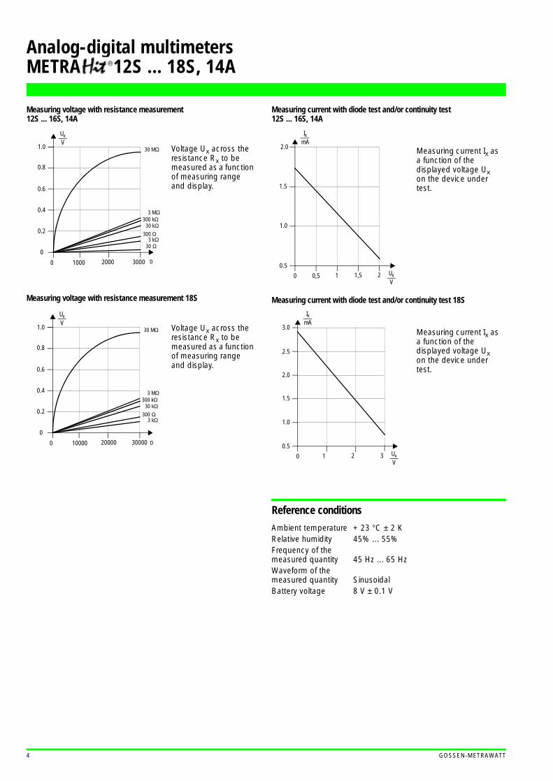
Measuring voltage with resistance measurement 12S ... 16S, 14A
Measuring voltage with resistance measurement 18S
Measuring current with diode test and/or continuity test 12S ... 16S, 14A
Measuring current with diode test and/or continuity test 18S
Reference conditions
Ambient temperature + 23 °C ± 2 KRelative humidity 45% ... 55%Frequency of the measured quantity 45 Hz ... 65 HzWaveform of themeasured quantity SinusoidalBattery voltage 8 V ± 0.1 V
1.0
0.8
0.6
0.4
0.2
0
0 1000 2000 3000 D
30 MΩ
3 MΩ300 kΩ
30 kΩ300 Ω
3 kΩ30 Ω
UxV
Voltage Ux across the resistance Rx to be measured as a function of measuring range and display.
Voltage Ux across the resistance Rx to be measured as a function of measuring range and display.
1.0
0.8
0.6
0.4
0.2
0
0 10000 20000 30000 D
30 MΩ
3 MΩ300 kΩ
30 kΩ300 Ω
3 kΩ
UxV
Measuring current Ix as a function of thedisplayed voltage Ux on the device under test.
UxV
0 0,5 1 1,5 2
0.5
1.0
1.5
2.0
IxmA
Measuring current Ix as a function of the displayed voltage Ux on the device under test.
UxV
0 1 2 3
0.5
1.0
2.0
3.0
IxmA
1.5
2.5
Analog-digital multimetersMETRA 12S ... 18S, 14A

GOSSEN-METRAWATT 5
Display
LCD field (65 mm x 30 mm) with analog indication and digital dis-play and with annunciators for unit of measurement, function and various special functions.
AnalogIndication LCD scale with pointerScale length 55 mm on V and A ;
47 mm on all other rangesScaling 5 ... 0 ... ± 30 with 35 scale
divisions on , 0 ... 30 with 30 scale divisions on all other ranges
Polarity indication With automatic reversalOverrange indication By triangleSampling rate 20 readings/s,
on Ω: 10 readings/s
DigitalDisplay / height of numerals
METRAHit 12S ... 16S, 14A:7-segment numerals / 15 mm
METRAHit 18S:7-segment numerals / 12 mm
Number of counts METRAHit 12S ... 16S, 14A:3 3/4 digit 3100 steps
METRAHit 18S:4 3/4 digit 31000 steps
Overrange display "OL" is shownPolarity display "–" sign is shown,
when positive pole to "⊥"Sampling rate 2 readings/s,
on Ω and °C: 1 reading/s
Display METRAHit 12S ... 16S, 14A
Display METRAHit 18S
1 Display with low battery voltage
2 Display with sound signal on
3 Symbol for "CONTINUOUSLY ON"
4 Digital display with indication of decimal point and polarity
5 Display with manual range selection as well as with data and MIN/MAX hold
6 Display of the selected function
7 Display of the unit of measurement
8 Display with overrange
9 Pointer for analog indication
10 Scale for analog indication
11 Indication that negative analog range is exceeded
12 Display of the unit °C when measuring temperature
13 Display with time counter switched on
3 4 5 6
7
891011
12
1
2
3 4 5 6
7
891011
13
1
2
Analog-digital multimetersMETRA 12S ... 18S, 14A
6 GOSSEN-METRAWATT
Influence quantities and variations for 12S ... 16S, 14A
1) With temperature: Error data is per 10 K change in temperature.With frequency: Error data is valid from a display of 300 digits.
2) With zero setting
3) With unknown waveform (crest factor CF > 2), the measurement must be made with manual range selection.
4) Except for sinusoidal waveform
5) From the time the symbol „ ” appears.
Influence quantities and variations for 18S
1) With zero setting
2) With temperature: Error data is per 10 K change in temperature.With frequency: Error data is valid from a display of 10 % of the measuring range.
3) With unknown waveform (crest factor CF > 2), the measurement must be made with manual range selection.
4) Except for sinusoidal waveform
5) From the time the symbol „ ” appears.
Influence quantity Influence rangeMeasured quantity/measuring range
Variation 1)
±(... % of meas. val. +... digits)12S ...14S 15S 16S
Temperature
0 °C ... +21 °C
and
+25 °C ... +40 °C
30/300 mV 1.0 + 3 1.0 + 13 ... 300 V 0.15 + 1 0.1 + 1
1000 V 0.2 + 1 0.1 + 1V 0.4 + 2 0.3 + 2
300 µA 2) ...300 mA
0.5 + 1 0.15 + 1
3 A / 10 (16) A 0.5 + 1A 0.75 + 1 0.75 + 3
30 Ω 2) 0,15 + 2300 Ω 0.25 + 2 0.15 + 2
3 kΩ ... 3 MΩ 0.15 + 1 0.1 + 130 MΩ 1.0 + 1 0.6 + 1
30 nF2) ... 3 µF — 0.5 + 230 µF — 2.0 + 2
Hz — 0.5 + 1% — ± 5 D
– 200 ... + 200 °C 0.5 K +2+ 200 ... + 850 °C 0.5 + 2
Frequency of the measured
quantity
15 Hz ... < 30 Hz
3 ... 300 V
— — 1.0 + 330 Hz ... < 45 Hz — — 0.5 + 3
> 65 Hz ... 400 Hz 2.0 + 3 0.5 + 3> 400 Hz ... 1 kHz 2.0 + 3 1.0 + 3> 1 kHz ... 20 kHz — — 2.0 + 315 Hz ... < 30 Hz
1000 V— — 1.0 + 3
30 Hz ... < 45 Hz — — 0.5 + 3> 65 Hz ... 1 kHz 3.0 + 3 2.0 + 315 Hz ... < 30 Hz
A— — 1.0 + 3
30 Hz ... < 45 Hz — — 0.5 + 3> 65 Hz ... 1 kHz 2.0 + 3 3.0 + 3
Waveform of the measured
quantity 3)
Crestfactor CF
1 ... 3V 4), A 4)
— —± 1 %of rdg.
> 3 ... 5 — —± 3 % of rdg.
Influence quantity Influence rangeMeasured quantity/measuring range
Variation
12S ... 16S, 14A
Battery voltage5) ... < 7.9 V
> 8.1 V ... 10.0 V
V ± 2 DV ± 4 DA ± 4 DA ± 6 D
30 Ω / 300 Ω / °C ± 4 D3 kΩ ... 30 MΩ ± 3 D
nF, µF ± 1 DHz ± 1 D% ± 1 D
Relative humidity
75 %
3 days
Meter off
V
A
ΩF
Hz
%
°C
1x inherent deviation
DATA ± 1 D
MIN / MAX V , A ± 2 D
0
1
2
3
4
5CF
0 500 V 1000 V0
1
2
3
4
5CF
0 1000 3000 D2000
Voltage measurement Current measurement
The permissible crest factor CF of the AC quantity to be measured is a functionof the displayed value:
Influence quantity Influence rangeMeasured quantity/measuring range 1)
Variation 2)
±(... % of meas. val. +... digits)
Temperature
-10 °C ... +21 °C
and
+25 °C ... +40 °C
V 0.05 + 3V ,V 0.2 + 30
300 µA / 3 mA 0.2 + 330 mA 0.1 + 3
300 mA ... 10 A 0.2 + 3300 µA ... 300 mA 0.3 + 30
3 A / 10 A 0.5 + 30300 Ω 0.1 + 5
3 kΩ ... 3 MΩ 0.1 + 330 MΩ 0.6 + 3
3 nF ... 3 µF 0.5 + 330 µF 2.0 + 3
Hz 0.1 + 3– 200 ... + 100 °C 0.5 Kelvin + 2 D+ 100 ... + 850 °C 0.5 + 2
Frequency ofthe measured
quantity
15 Hz ... < 45 Hz300 mV
1.0 + 20> 65 Hz ... 200 Hz 1.0 + 2015 Hz ... < 30 Hz
3 ... 300 V
1.0 + 2030 Hz ... < 45 Hz 0.5 + 20
> 65 Hz ... 400 Hz 0.5 + 20> 400 Hz ... 1 kHz 1.0 + 20> 1 kHz ... 20 kHz 2.0 + 2015 Hz ... < 30 Hz
1000 V1.0 + 20
30 Hz ... < 45 Hz 0.5 + 20> 65 Hz ... 1 kHz 2.0 + 2015 Hz ... < 45 Hz
A1.0 + 20
> 65 Hz ... 1 kHz 1.0 + 20
Waveform of the measured
quantity 3)
Crestfactor CF
1 ... 3V 4), A 4) ± 1 % of rdg.
> 3 ... 5 ± 3 % of of rdg.
Influence quantity Influence rangeMeasured quantity/measuring range 1)
Variation
Battery voltage5) ... < 7.9 V
> 8.1 V ... 10.0 V
V ± 6 DV ± 30 DA ± 10 DA ± 30 D
Ω ± 10 D3 nF ... 30 µF ± 5 D
Hz ± 6 D°C ± 5 D
Relative humidity
75%
3 days
Meter off
V, dB, A, ΩF, Hz
°C
1x inherent deviation
DATAV, dB, A, Ω, Hz ± 10 D
F ± 1 D
MIN / MAXV, dB, A, Ω, Hz ± 20 D
°C, F ± 2 D
0
1
2
3
4
5CF
0 500 V 1000 V0
1
2
3
4
5CF
0 10000 3000020000
Voltage measurement Current measurement
The permissible crest factor CF of the AC quantity to be measured is a functionof the displayed value:
D
Analog-digital multimetersMETRA 12S ... 18S, 14A

GOSSEN-METRAWATT 7
Response time
Response time for 12S ... 16S, 14A (after manual range selection)
Power supply
Battery 9-V flat cell battery;manganese-dioxide cell according to IEC 6 F 22, alkaline-manganese cell according to IEC 6 LR 61or corresponding NiCd storage battery
Operating time With alkaline-manganese cell:METRAHit 12...16S, 14A:approx. 750 hours on V , Aapprox. 200 hours on V , A (12S...15S, 14A)approx. 150 hours on , A (16S)with interface operation times x 0.7METRAHit 18S:approx. 300 hours on Vapprox. 150 hours on V , A A
Battery test Automatic display of the „ ” symbol, when the battery voltage drops below approximately 7 V.
Fuses
Fuse link for theranges up to 300 mA FF 1.6/500 G; 6.3 mm x 32 mm;
switching capacity 20 kA on 500 V and ohmic load; in connection with power diodes protects all current measuring ranges up to 300 mA
Fuse link for rangesup to 10 A Switching capacity 100 kA on 600 V
and ohmic load; protects the 3 A and 10 A ranges up to 600 V
Response time for 18S (after manual range selection)
Electrical safety
Protection class II according to IEC 348/DIN VDE 0411 and IEC 1010-1/EN 61010-1/VDE 0411-1
Overvoltage category II IIINominal voltage 1000 V 600 VDegree of pollution 2 2Nominal insulation voltage 1000 V acc. to IEC 348 / DIN VDE 0411Test voltage 6 kV~ acc. to IEC 348 / DIN VDE 0411
Electromagnetic compatibility EMC
Emission EN 50081-1:1992 / EN 55022:1987 class B
Immunity EN 50082-1:1992/ IEC 801-2:1991 8 kV air discharge/ IEC 801-3:1984 3 V/m/ IEC 801-4:1988 0.5 kV
Data interface
Type RS-232C, serial, according to DIN 19 241Data transmission Optical, with infrared light through the caseBaud rate 8192 bit/s
Influence quantity
Influence rangeMeas. ranges
12S ... 16SDamping
Commonmode voltage
Disturbance variable max. 1000 V V > 120 dB
Disturbance variable max. 1000 V
50 Hz, 60 Hz sinusoidal
3 V ,30 V
> 80 dB
300 V > 70 dB
1000 V > 60 dB
Normal mode voltage
Disturbance variable V ,nom. value of meas. range at a time,
max. 1000 V , 50 Hz, 60 Hz sinusoidal
V > 50 dB
Disturbance variable max. 1000 V V > 110 dB
Measured quantity/measuring range
Response timeLeap function of
the measured quantityof analogindication
of digital display
V , V ,
A , A0.7 s 1.5 s
from 0 to 80 % of the upper range limit
30 Ω...3 MΩ 1.5 s 2 sfrom ∞ to 50 %
of the upper range limit30 MΩ 4 s 5 s
0.7 s 1.5 s
nF, µF, °C max. 1... 3 s
from 0 to 50 % of the upper range limit
300 Hz, 3 kHz max. 2 s
30, 100 kHz max. 0.7 s
% (1 Hz) max. 9 s
% (≥10 Hz) max. 2.5 s
Influence quantity
Influence rangeMeas. ranges
18S Damping
Common mode voltage
Disturbance variable max. 1000 V V > 120 dB
Disturbance variable max. 1000 V
50 Hz, 60 Hz sinusoidal
300 mV ...30 V
> 80 dB
300 V > 70 dB1000 V > 60 dB
Normal mode voltage
Disturbance variable V ,nom. value of meas. range at a time,
max. 1000 V , 50 Hz, 60 Hz sinusoidal
V > 48dB
Disturbance variable max. 1000 V V > 110dB
Measured quantity/measuring range
Response timeLeap function of
the measured quantityof analogindication
of digital display
V , V ,
A , A0.7 s
1.5 s300 mV : 8 s
from 0 to 80 % of the upper range limit
300 Ω ... 3 MΩ 1.5 s 2 sfrom ∞ to 50 %
of the upper range limit30 MΩ 4 s 5 s
0.7 s 1,5 s
3 nF ... 300 µF max. 2 s max. 2 s
from 0 to 50 % of the upper range limit
3 000 µF max. 7 s max. 7 s10 000 µF max. 14 s max. 14 s
>10 Hz max. 1.5 s max. 1.5 s
°C max. 3 s
Analog-digital multimetersMETRA 12S ... 18S, 14A
8 GOSSEN-METRAWATT
Environmental conditions
Working temperature range METRAHit 12S ... 16S, 14A:
−10 °C ... + 50 °CMETRAHit 18S:−20 °C ... + 50 °C
Storagetemperature range − 25 °C ... + 70 °C (excl. batteries)Climatic class METRAHit 12S ... 16S,14A:
2z/−10/50/70/75 % with reference to VDI/VDE 3540METRAHit 18S:2z/−20/50/70/75 %with reference to VDI/VDE 3540
Altitude above sea level Up to 2000 m
Mechanical configuration
Protection type For meters: IP 50,for connection sockets: IP 20
Dimensions 84 mm x 195 mm x 35 mmWeight 0.35 kg, approx., incl.battery
Scope of delivery
1 multimeter1 lead set KS17-21 copy of operating instructions1 test certificate1 rubber holster GH18 with tilt stand and carrying strap
(except for 12S)
Warranty
3 years against defects in materials and workmanship1 year for the calibration
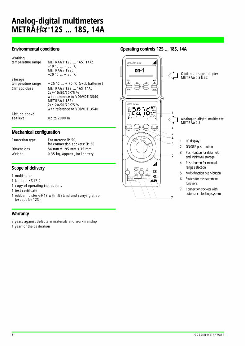
Operating controls 12S ... 18S, 14A
1
2
34
5
6
7
on-1Option storage adapter METRAHit SI232
Analog-to-digital multimeterMETRAHit S
16S
F
1 LC display
2 ON/OFF push-button
3 Push-button for data hold and MIN/MAX storage
4 Push-button for manual range selection
5 Multi-function push-button
6 Switch for measurement functions
7 Connection sockets with automatic blocking system
Analog-digital multimetersMETRA 12S ... 18S, 14A

GOSSEN-METRAWATT 9
Accessories
Temperature sensorFor the measurement of temperatures on the range from–40 ... 600 °C and/or –50...550 °C with METRAHit S multimeters, the following temperature sensors are particularly suited:
TF550 oven sensor and TF220 water-proof sensorThe TF550 sensor is especially suited for service applications for household appliances, i.e. for measurements in ovens to +500 °C. The TF220 sensor enables problem-free temperature measure-ments in gases and liquids such as water temperature in washing machines, transmission oil temperature and air temperatures in freezers and air conditioners.
TS ChipsetDue to its compact size, this temperature sensor is suited for measurements taken at constricted points, e.g. when the sensor is glued to a temperature sensitive component. It is delivered in sets of 10 sensor elements.
RI adapterThe RI adapter is a load resistor, which reduces the input resis-tance of concurrent measuring instruments from about 10 MΩ to about 200 kΩ.
The RI adapter is plugged onto a measuring instrument with the help of safety sockets, and reduces the measuring point load resistance to about 198 kΩ with its integrated 200 kΩ resistor. Thus voltages, which are generated by high imped-ance interference (e.g. capacitive interference) are charged with a rela-tively low impedance. This causes a sharp drop in voltage at the measur-ing point. An interrupted or faulty cable at the measuring point is thus rapidly detected.
Temperature sensor Z3409 TF550 TF220 TS Chipset
Sensor element Pt100 Pt100 Pt1000 Pt100
Length sensor element l1 130 mm 40 mm 39 mm 2.3 mm
Length sensor element l2 1 m 1.5 m 1 m 10 mm
Temperature range –40 ... +500 °C –50 ... +500 °C –50 ... +220 °C –50 ... +500 °C
Accuracy acc. to DIN EN 60751 / IEC 751
Class A Class B
Inherent deviation 0 °C: 0.15 K 0 °C: 0.3 K 0 °C: 0.3 K 0 °C: 0.4 K
Inherent deviation 500 °C: 1.35 K 500 °C: 3.1 K 220 °C: 1.4 K 500 °C: 3.1 K
Response time T90 water 5 s 8 s 0.3 s
Response time T90 air 33 s 15 s
Cable
Conductor Stranded wire, 2 x 0.35 mm2 2 x 0.25 mm ∅ / Ni-Pt
Outer insulating sleeve PVC V4A braided Teflon —
Insulation PVC Glass silk Teflon —
l1* 100
∅ 3.2red
black
l2*
∅ 22
l1* l2*
∅ 4 red
black
flexible
1,50,63
1,4
2
l1* l2*
Z3409
TF550TF220
TS Chipset
* Values see table above
Z101A200K
19 mm
DMM
KS17-2
Analog-digital multimetersMETRA 12S ... 18S, 14A
10 GOSSEN-METRAWATT
Storage adapter SI232
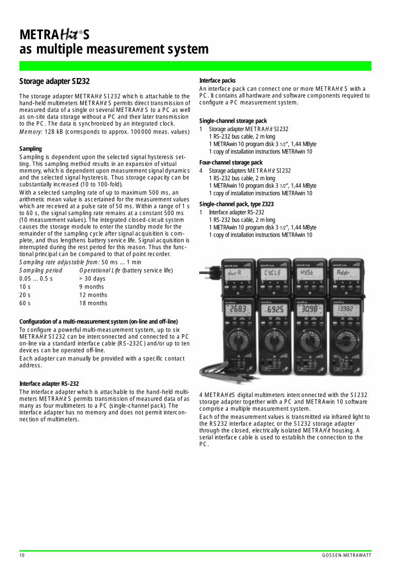
The storage adapter METRAHit SI 232 which is attachable to the hand-held multimeters METRAHit S permits direct transmission of measured data of a single or several METRAHit S to a PC as well as on-site data storage without a PC and their later transmission to the PC. The data is synchronized by an integrated clock.Memory: 128 kB (corresponds to approx. 100000 meas. values)
SamplingSampling is dependent upon the selected signal hysteresis set-ting. This sampling method results in an expansion of virtual memory, which is dependent upon measurement signal dynamics and the selected signal hysteresis. Thus storage capacity can be substantially increased (10 to 100-fold).With a selected sampling rate of up to maximum 500 ms, an arithmetic mean value is ascertained for the measurement values which are received at a pulse rate of 50 ms. Within a range of 1 s to 60 s, the signal sampling rate remains at a constant 500 ms (10 measurement values). The integrated closed-circuit system causes the storage module to enter the standby mode for the remainder of the sampling cycle after signal acquisition is com-plete, and thus lengthens battery service life. Signal acquisition is interrupted during the rest period for this reason. Thus the func-tional principal can be compared to that of point recorder.Sampling rate adjustable from: 50 ms ... 1 minSampling period Operational Life (battery service life)0.05 ... 0.5 s > 30 days10 s 9 months20 s 12 months60 s 18 months
Configuration of a multi-measurement system (on-line and off-line)To configure a powerful multi-measurement system, up to six METRAHit SI 232 can be interconnected and connected to a PC on-line via a standard interface cable (RS-232C) and/or up to ten devices can be operated off-line.Each adapter can manually be provided with a specific contact address.
Interface adapter RS-232The interface adapter which is attachable to the hand-held multi-meters METRAHit S permits transmission of measured data of as many as four multimeters to a PC (single-channel pack). The interface adapter has no memory and does not permit intercon-nection of multimeters.
Interface packsAn interface pack can connect one or more METRAHit S with a PC. It contains all hardware and software components required to configure a PC measurement system.
Single-channel storage pack1 Storage adapter METRAHit SI 232
1 RS-232 bus cable, 2 m long1 METRAwin 10 program disk 3 1/2“, 1,44 MByte1 copy of installation instructions METRAwin 10
Four-channel storage pack4 Storage adapters METRAHit SI 232
1 RS-232 bus cable, 2 m long1 METRAwin 10 program disk 3 1/2“, 1,44 MByte1 copy of installation instructions METRAwin 10
Single-channel pack, type Z3231 Interface adapter RS-232
1 RS-232 bus cable, 2 m long1 METRAwin 10 program disk 3 1/2", 1,44 MByte 1 copy of installation instructions METRAwin 10
4 METRAHitS digital multimeters interconnected with the SI 232 storage adapter together with a PC and METRAwin 10 software comprise a multiple measurement system.Each of the measurement values is transmitted via infrared light to the RS232 interface adapter, or the SI 232 storage adapter through the closed, electrically isolated METRAHit housing. A serial interface cable is used to establish the connection to the PC.
METRA Sas multiple measurement system
GOSSEN-METRAWATT 11
METRAwin 10 software
METRAwin 10 software (can be run with DOS or WINDOWS) is used for the processing and representation of measurement data at a PC. Sampling in the on-line mode can be performed manu-ally with an adjustable sampling interval, or dependent upon sig-nal dynamics (with adjustable signal hysteresis). Storage in the ASCII format is controlled with two trigger thresholds per mea-surement channel, as well as with the internal clock.
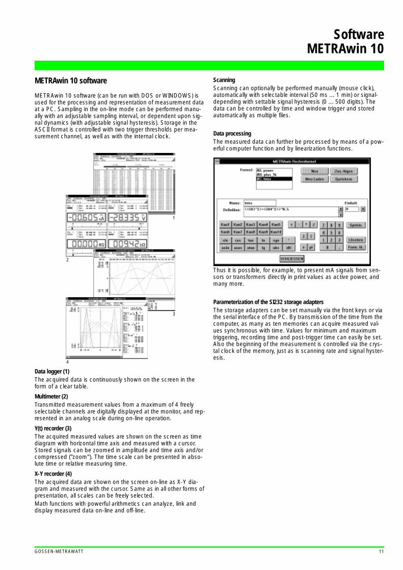
Data logger (1)The acquired data is continuously shown on the screen in the form of a clear table.
Multimeter (2)Transmitted measurement values from a maximum of 4 freely selectable channels are digitally displayed at the monitor, and rep-resented in an analog scale during on-line operation.
Y(t) recorder (3)The acquired measured values are shown on the screen as time diagram with horizontal time axis and measured with a cursor. Stored signals can be zoomed in amplitude and time axis and/or compressed ("zoom"). The time scale can be presented in abso-lute time or relative measuring time.
X-Y recorder (4)The acquired data are shown on the screen on-line as X-Y dia-gram and measured with the cursor. Same as in all other forms of presentation, all scales can be freely selected.Math functions with powerful arithmetics can analyze, link and display measured data on-line and off-line.
ScanningScanning can optionally be performed manually (mouse click), automatically with selectable interval (50 ms ... 1 min) or signal-depending with settable signal hysteresis (0 ... 500 digits). The data can be controlled by time and window trigger and stored automatically as multiple files.
Data processingThe measured data can further be processed by means of a pow-erful computer function and by linearization functions.
Thus it is possible, for example, to present mA signals from sen-sors or transformers directly in print values as active power, and many more.
Parameterization of the SI232 storage adaptersThe storage adapters can be set manually via the front keys or via the serial interface of the PC. By transmission of the time from the computer, as many as ten memories can acquire measured val-ues synchronous with time. Values for minimum and maximum triggering, recording time and post-trigger time can easily be set. Also the beginning of the measurement is controlled via the crys-tal clock of the memory, just as is scanning rate and signal hyster-esis.
1
2
3
4
SoftwareMETRAwin 10

Printed in Germany ⋅ Subject to change without notice ⋅ 4/6.97 Ordering no. 3-348-855-03
Analog-digital multimetersMETRA 12S ... 18S, 14A
Company address:Thomas-Mann-Straße 16 - 20D-90471 NürnbergTelefon (0911) 8602-0Telefax (0911) 8602-669
GOSSEN-METRAWATT GMBHD-90327 Nürnberg CAM
ILLE B
AUER
MET
RAW
ATT
GOSSEN
Carrying bag F829
Ever-ready case F836 Protective rubber holster GH18
Measuring adapter for leakage currentThis measuring adapter serves as mea-suring device for the METRAHit 18S for the measurement of the contact potential according to DIN VDE 0107 (clause 10) and for the meas. of continuously flowing leakage currents and patient auxiliary cur-rents acc. to DIN VDE 0750, part 1, IEC 601-1 and EN 60601-1.1990.
Order code
Designation Type Ident Number
Multimeter
METRAHit 12SMETRAHit 13SMETRAHit 14AMETRAHit 14SMETRAHit 15SMETRAHit 16SMETRAHit 18S
GTM 2012 100 R0003GTM 2013 000 R0003GTM 2014 000 R0007GTM 2014 000 R0003GTM 2015 000 R0003GTM 2016 000 R0003GTM 2018 000 R0003
Single-channel storage pack includ-ing 4 storage adapters SI 232, cable and software METRAwin 10 1-CH. Pack GTZ 3231 020 R0001
Four-channel storage pack including storage adapter SI 232, cable and software METRAwin 10 4-CH. Pack GTZ 3234 020 R0001
Storage adapter for METRAHit S SI232 GTZ 3242 020 R0001
Single-channel pack including cable and software METRAwin 10 Z3231 GTZ 3231 000 R0001
Interface adapter RS-232 (contained in Z3231) Z3242 GTZ 3242 000 R0001
Interface cable RS-232, 2 m, (contained in Z3231) Z3241 GTZ 3241 000 R0001
METRAwin 10 software update Z3240 GTZ 3240 000 R0001
Temperature sensor Pt100 for sur-face and immersion measurements, –40 ... +600 °C Z3409 GTZ 3409 000 R0001
Temperature sensor Pt1000 for measurements in gases and liquids –50 ... +220 °C TF220 Z102A
Oven sensor Pt100, –50 ... +550 °C TF550 GTZ 3408 000 R0001
10 temperature sensors Pt100 ,affixable, up to –50 .. +550 °C TS-Chipset GTZ 3406 000 R0001
Measuring adapter for leakage current for METRAHit 18S Z3450 GTZ 3450 000 R0001
Ri adapter 200 kΩ/230 V R200K Z101A
Carrying bag F829 GTZ 3301 000 R0003
Ever-ready case F836 GTZ 3302 000 R0001
Ever-ready case for 2 METRAHit S with SI232 and accessories F840 GTZ 3302 001 R0001
Protective rubber holster and carrying strap GH18 GTZ 3212 000 R0001
Electric set consisting of:carrying bag F829, clip-on current transformer WZ11 (15 ... 180 A~, 1 mA/1 A~) and test leads Electric-Set GTZ 3236 000 R0001
Fuse link (10 each) FF1,6/500G GTY 3578 136 P0001
Fuse link (10 each) 16 A/600 V GTY 3578 176 P0001