analog sensors for motion measurement. topics introduction motion transducers potentiometers...
TRANSCRIPT
ANALOG SENSORS FOR MOTION MEASUREMENT
TOPICS
Introduction Motion transducers Potentiometers Variable inductance transducers Permanent magnet transducers Eddy current transducers Variable capacitance transducers Piezoelectric transducers Design criterion for control systems
INTRODUCTION
• Measurement of plant outputs and feedback signals are very important.
• The measurement subsystem in a control system contains sensors and transducers that detect measurands and convert them into acceptable signals- typically voltages
• Sensor: A device for measuring some quantity. The sensor usually converts the measurement space to an electrical signal.
• Transducer: It is a device, that converts one type of energy to another. • Transducers are used for compensation in different plants and systems.• Help in reducing the sensitivity of a system to parameter change.• Several analog sensor-transducer devices are commonly used in control
system instrumentation• We will deal with several analog motion transducers.
MOTION TRANSDUCERS
• Motion here means the four kinematics variables Displacement Velocity Acceleration Jerk
• Each variable is a time derivation of the preceding one.
• Motion measurement is extremely important for system’s or plant proper functioning.
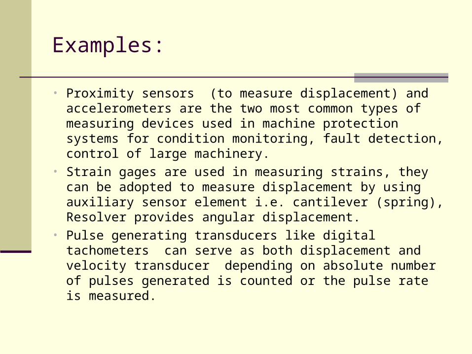
Examples:
• Proximity sensors (to measure displacement) and accelerometers are the two most common types of measuring devices used in machine protection systems for condition monitoring, fault detection, control of large machinery.
• Strain gages are used in measuring strains, they can be adopted to measure displacement by using auxiliary sensor element i.e. cantilever (spring), Resolver provides angular displacement.
• Pulse generating transducers like digital tachometers can serve as both displacement and velocity transducer depending on absolute number of pulses generated is counted or the pulse rate is measured.
Motion Transducers
Motion transducers will be limited mainly to following types of devices:
Potentiometers Variable inductance transducers Eddy current transducers Variable capacitance transducers Piezoelectric transducers
Potentiometers
vo
(Measurement)
x
(Measurand)
vref
(Supply)
Resistive Element
Wiper Arm
No Current
+
- i
ov
vref
Nonzero Current
+
- i
Z Load
Impedance
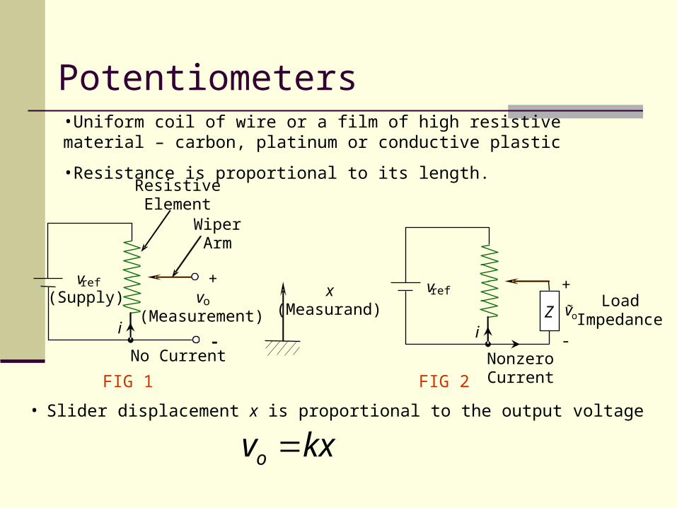
•Uniform coil of wire or a film of high resistive material – carbon, platinum or conductive plastic
•Resistance is proportional to its length.
• Slider displacement x is proportional to the output voltage
kxvo
FIG 1 FIG 2
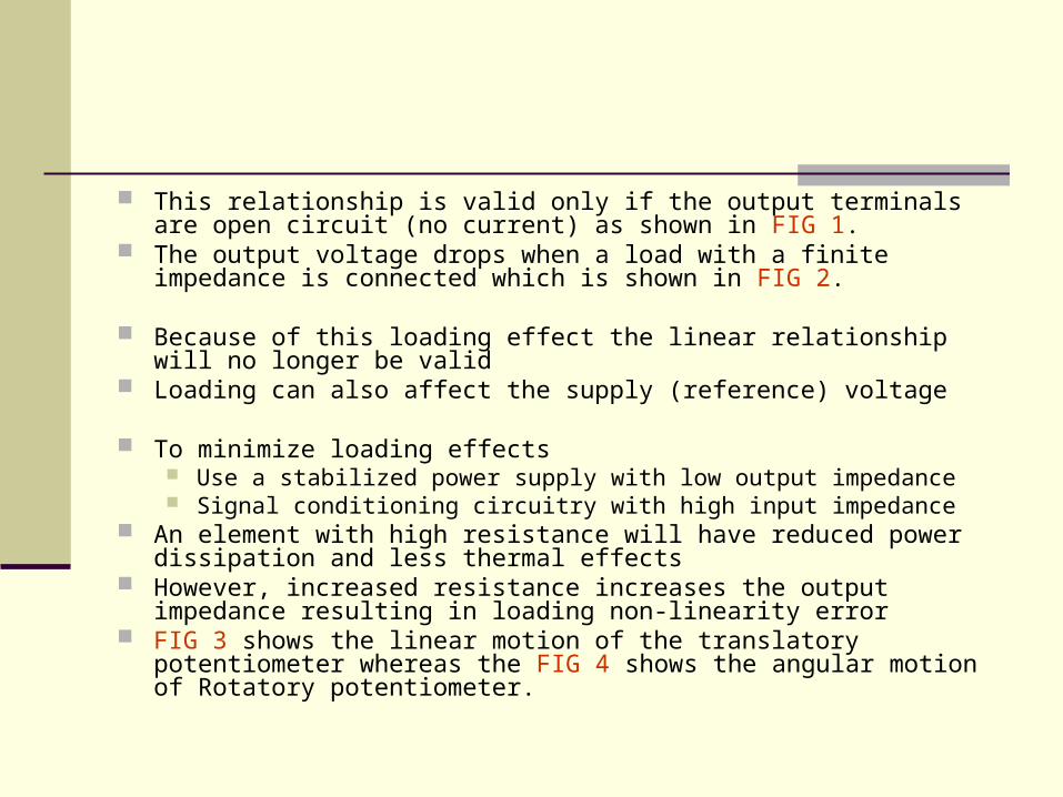
This relationship is valid only if the output terminals are open circuit (no current) as shown in FIG 1.
The output voltage drops when a load with a finite impedance is connected which is shown in FIG 2.
Because of this loading effect the linear relationship will no longer be valid
Loading can also affect the supply (reference) voltage
To minimize loading effects Use a stabilized power supply with low output impedance Signal conditioning circuitry with high input impedance
An element with high resistance will have reduced power dissipation and less thermal effects
However, increased resistance increases the output impedance resulting in loading non-linearity error
FIG 3 shows the linear motion of the translatory potentiometer whereas the FIG 4 shows the angular motion of Rotatory potentiometer.
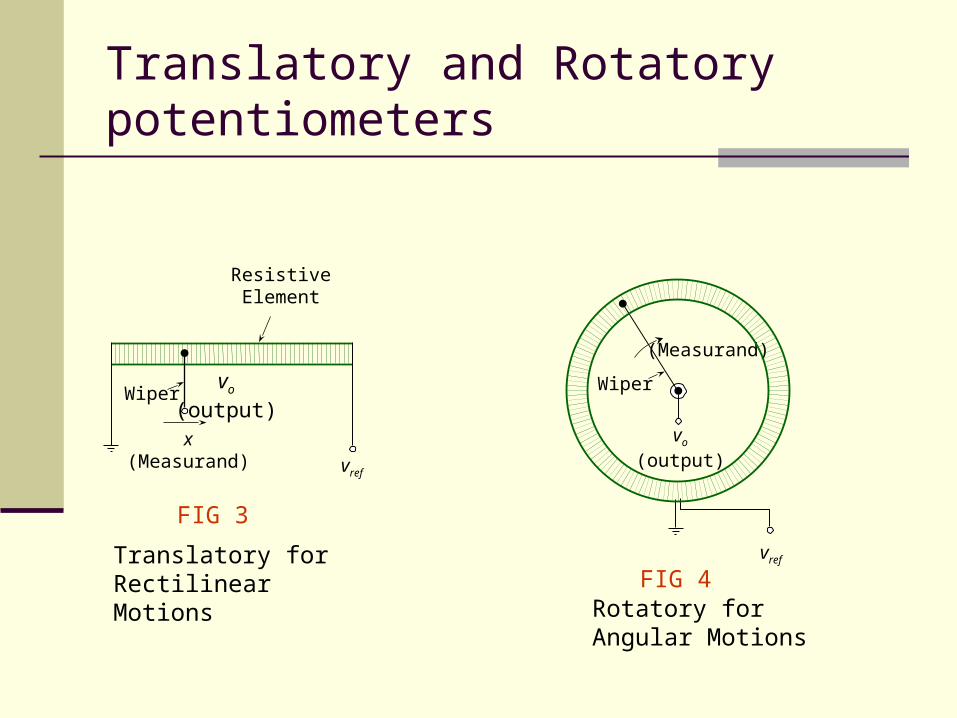
Translatory and Rotatory potentiometers
Wipervo
(output)
vref
x(Measurand)
ResistiveElement
Wiper
vo
(output)
(Measurand)
Translatory for Rectilinear Motions
vref
Rotatory for Angular Motions
FIG 3
FIG 4
VARIABLE-INDUCTANCE TRANSDUCERS
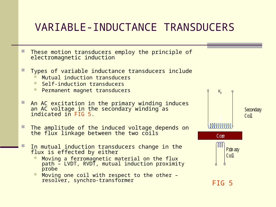
These motion transducers employ the principle of electromagnetic induction
Types of variable inductance transducers include Mutual induction transducers Self-induction transducers Permanent magnet transducers
An AC excitation in the primary winding induces an AC voltage in the secondary winding as indicated in FIG 5.
The amplitude of the induced voltage depends on the flux linkage between the two coils
In mutual induction transducers change in the flux is effected by either
Moving a ferromagnetic material on the flux path – LVDT, RVDT, mutual induction proximity probe
Moving one coil with respect to the other – resolver, synchro-transformer
Core
vo
Secondary Coil
Primary Coil
FIG 5
MUTUAL INDUCTANCE TRANSDUCER(Linear variable differential transformer (LVDT))
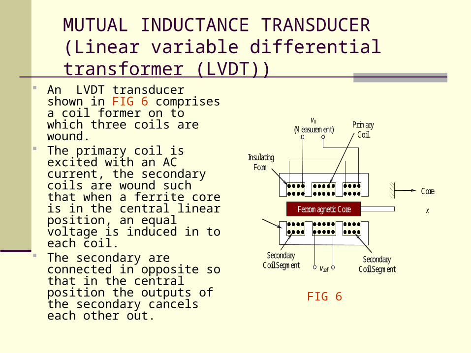
An LVDT transducer shown in FIG 6 comprises a coil former on to which three coils are wound.
The primary coil is excited with an AC current, the secondary coils are wound such that when a ferrite core is in the central linear position, an equal voltage is induced in to each coil.
The secondary are connected in opposite so that in the central position the outputs of the secondary cancels each other out.
Ferromagnetic Core
Core
x
vo
(Measurement)
vref
Primary Coil
Insulating Form
Secondary Coil Segment
Secondary Coil Segment
FIG 6
LINEAR VARIABLE DIFFERENTIAL TRANSFORMER
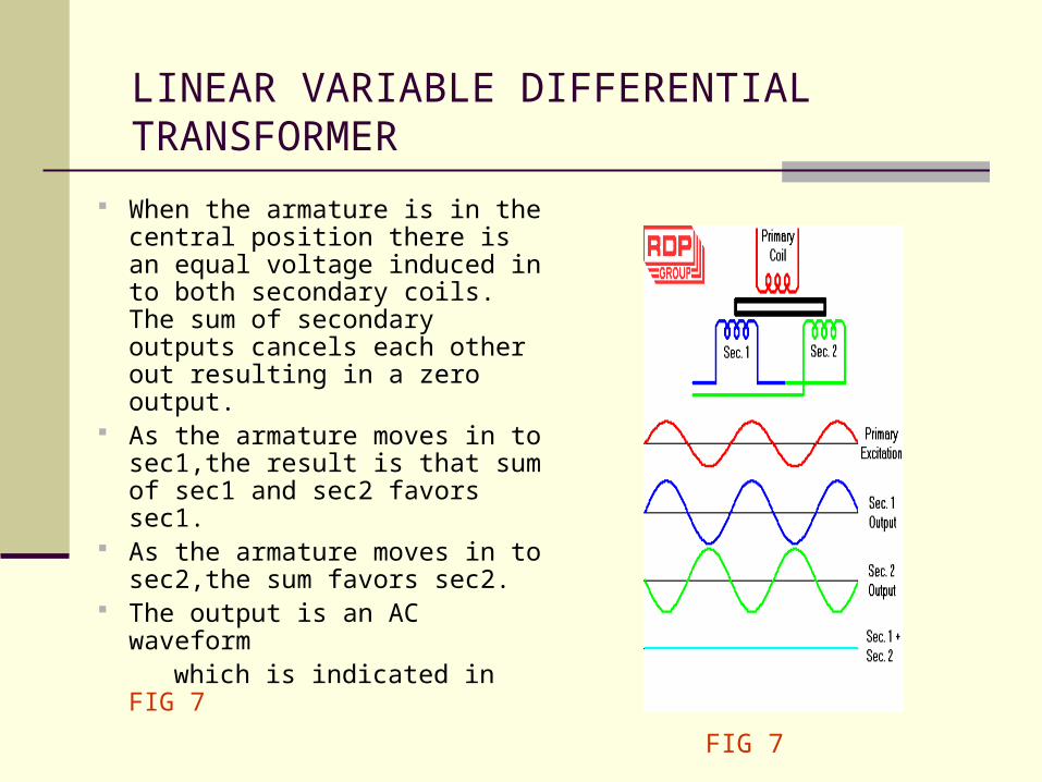
When the armature is in the central position there is an equal voltage induced in to both secondary coils. The sum of secondary outputs cancels each other out resulting in a zero output.
As the armature moves in to sec1,the result is that sum of sec1 and sec2 favors sec1.
As the armature moves in to sec2,the sum favors sec2.
The output is an AC waveform which is indicated in FIG 7
FIG 7
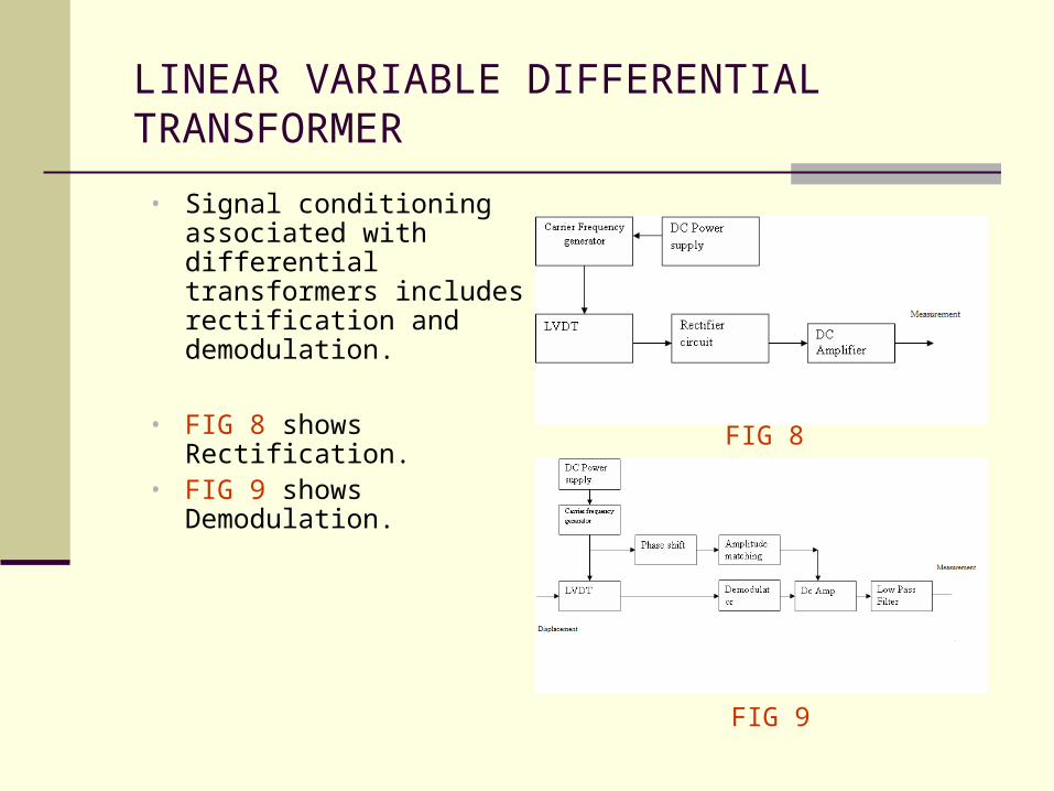
LINEAR VARIABLE DIFFERENTIAL TRANSFORMER
• Signal conditioning associated with differential transformers includes rectification and demodulation.
• FIG 8 shows Rectification.• FIG 9 shows Demodulation. FIG 8
FIG 9
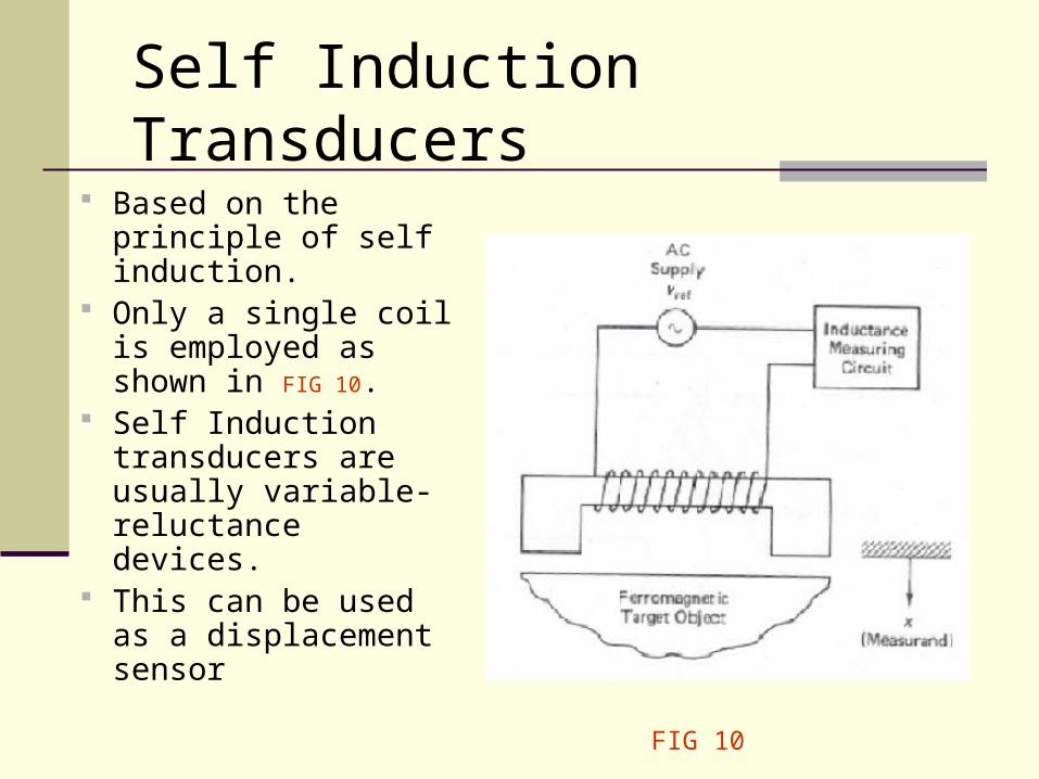
Self Induction Transducers
Based on the principle of self induction.
Only a single coil is employed as shown in FIG 10.
Self Induction transducers are usually variable-reluctance devices.
This can be used as a displacement sensor
FIG 10
Permanent Magnet Transducers
A permanent magnet is used to generate a uniform and steady magnetic field.
Permanent magnet transducers are used in measuring speed.
Two types of speed are measured. Rectilinear speed Rectilinear velocity transducer shown in FIG 11 is
used to measure rectilinear speed Angular speed. DC tachometer-generator in FIG 12 and AC
tachometer-generator are used in measuring angular speed.
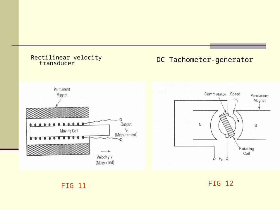
Rectilinear velocity transducer DC Tachometer-generator
FIG 11 FIG 12
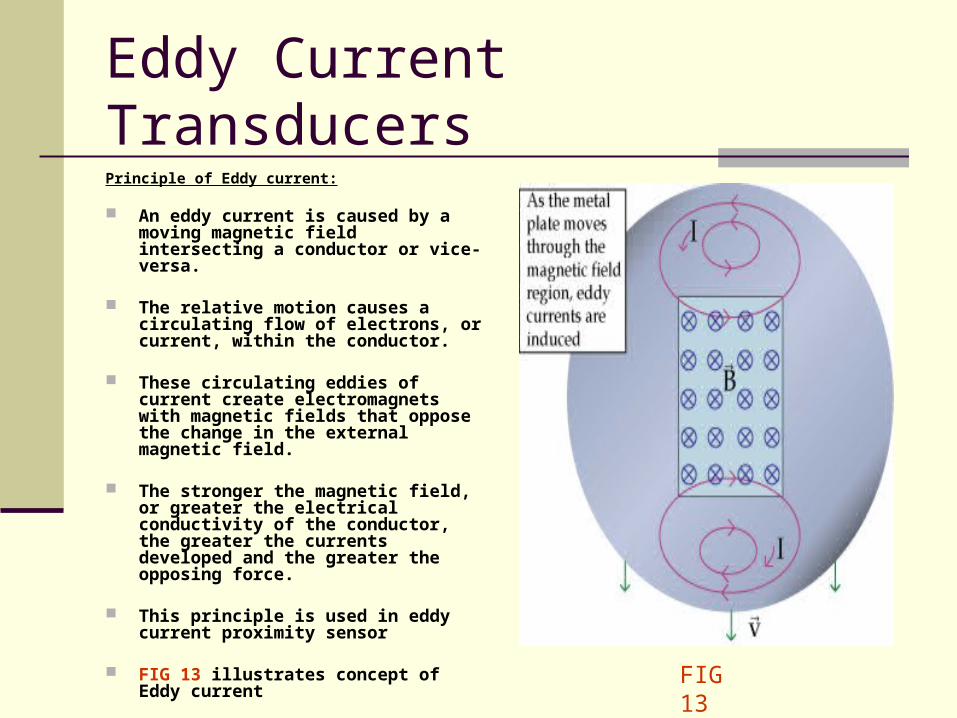
Eddy Current TransducersPrinciple of Eddy current:
An eddy current is caused by a moving magnetic field intersecting a conductor or vice-versa.
The relative motion causes a circulating flow of electrons, or current, within the conductor.
These circulating eddies of current create electromagnets with magnetic fields that oppose the change in the external magnetic field.
The stronger the magnetic field, or greater the electrical conductivity of the conductor, the greater the currents developed and the greater the opposing force.
This principle is used in eddy current proximity sensor
FIG 13 illustrates concept of Eddy current FIG 13
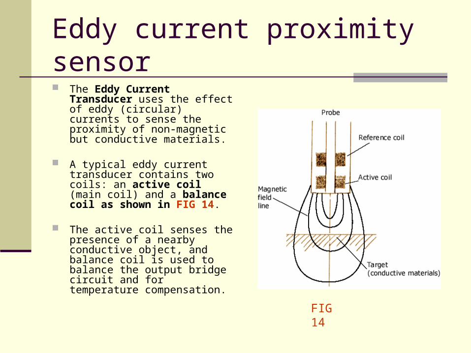
Eddy current proximity sensor The Eddy Current Transducer
uses the effect of eddy (circular) currents to sense the proximity of non-magnetic but conductive materials.
A typical eddy current transducer contains two coils: an active coil (main coil) and a balance coil as shown in FIG 14.
The active coil senses the presence of a nearby conductive object, and balance coil is used to balance the output bridge circuit and for temperature compensation.
FIG 14
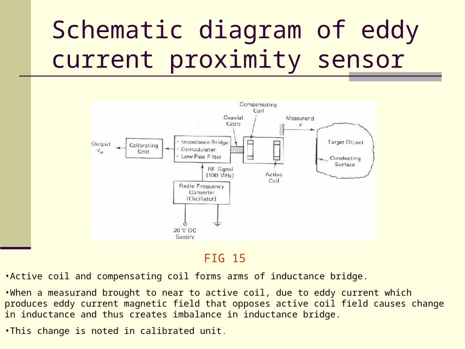
Schematic diagram of eddy current proximity sensor
FIG 15
•Active coil and compensating coil forms arms of inductance bridge.
•When a measurand brought to near to active coil, due to eddy current which produces eddy current magnetic field that opposes active coil field causes change in inductance and thus creates imbalance in inductance bridge.
•This change is noted in calibrated unit.
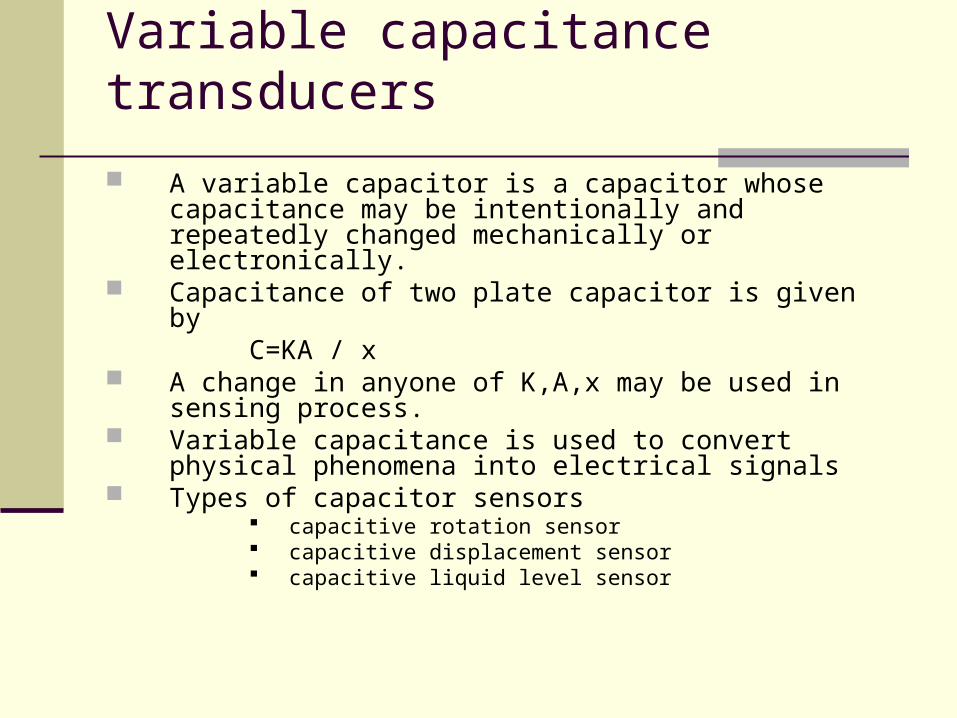
Variable capacitance transducers
A variable capacitor is a capacitor whose capacitance may be intentionally and repeatedly changed mechanically or electronically.
Capacitance of two plate capacitor is given by C=KA / x A change in anyone of K,A,x may be used in sensing
process. Variable capacitance is used to convert physical phenomena
into electrical signals Types of capacitor sensors
capacitive rotation sensor capacitive displacement sensor capacitive liquid level sensor
Variable capacitance transducers
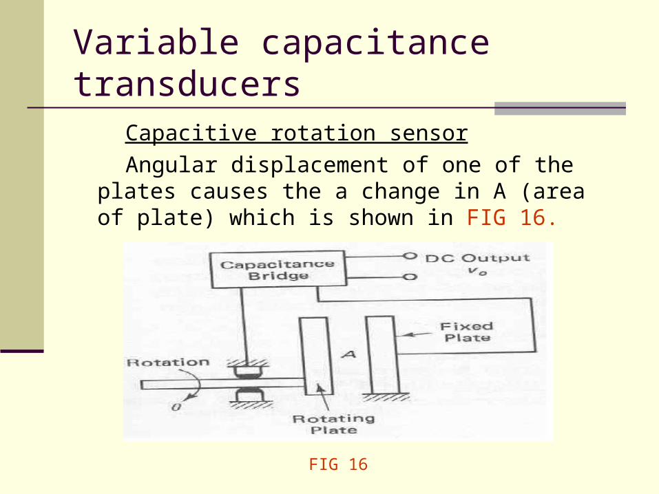
Capacitive rotation sensor
Angular displacement of one of the plates causes the a change in A (area of plate) which is shown in FIG 16.
FIG 16
Variable capacitance transducers
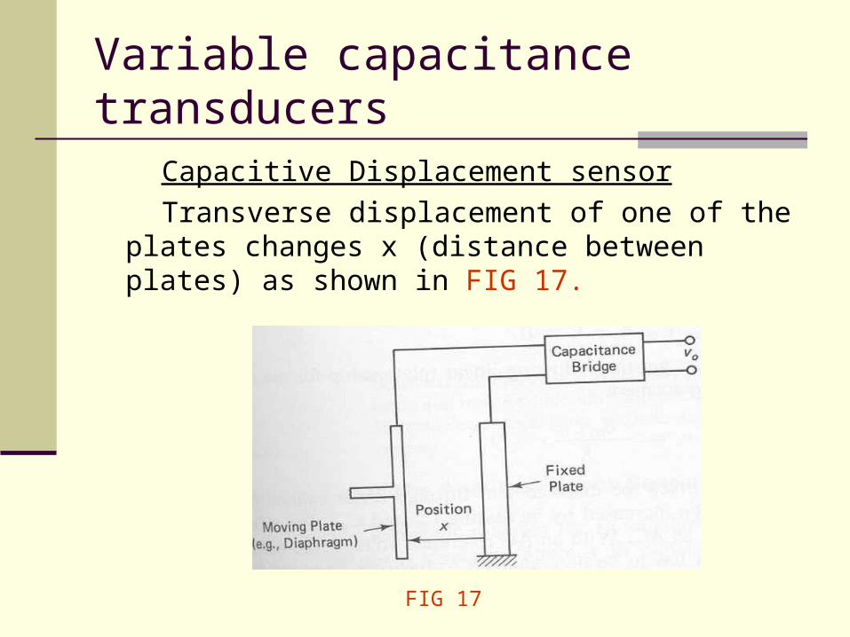
Capacitive Displacement sensor
Transverse displacement of one of the plates changes x (distance between plates) as shown in FIG 17.
FIG 17
Variable capacitance transducers
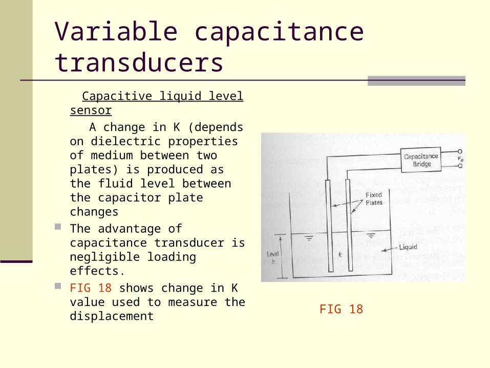
Capacitive liquid level sensor
A change in K (depends on dielectric properties of medium between two plates) is produced as the fluid level between the capacitor plate changes
The advantage of capacitance transducer is negligible loading effects.
FIG 18 shows change in K value used to measure the displacement FIG 18
Piezoelectric transducers
• Piezoelectric materials: Barium titanate, single crystal quartz.
• Piezoelectric Effect:
When mechanical stress or strain is applied to the piezoelectric material, generates an electric charge and associated potential difference.
• The direct application of piezoelectric effect is used in pressure and strain measuring devices
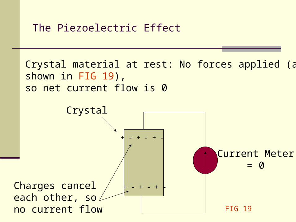
The Piezoelectric Effect
Crystal
Current Meter = 0
+ - + - + -
+ - + - + -Charges canceleach other, sono current flow
Crystal material at rest: No forces applied (as shown in FIG 19),so net current flow is 0
FIG 19
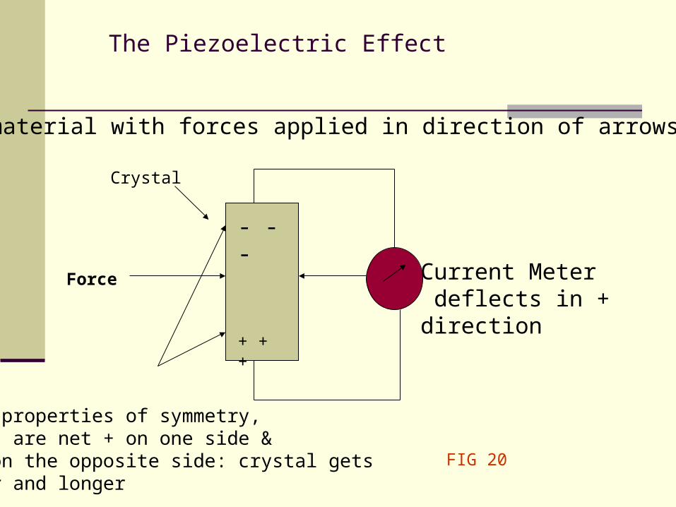
The Piezoelectric Effect
Current Meter deflects in + direction
- - -
Due to properties of symmetry,charges are net + on one side & net - on the opposite side: crystal getsthinner and longer
Crystal material with forces applied in direction of arrows (FIG 20).
+ + +
Force
Crystal
FIG 20
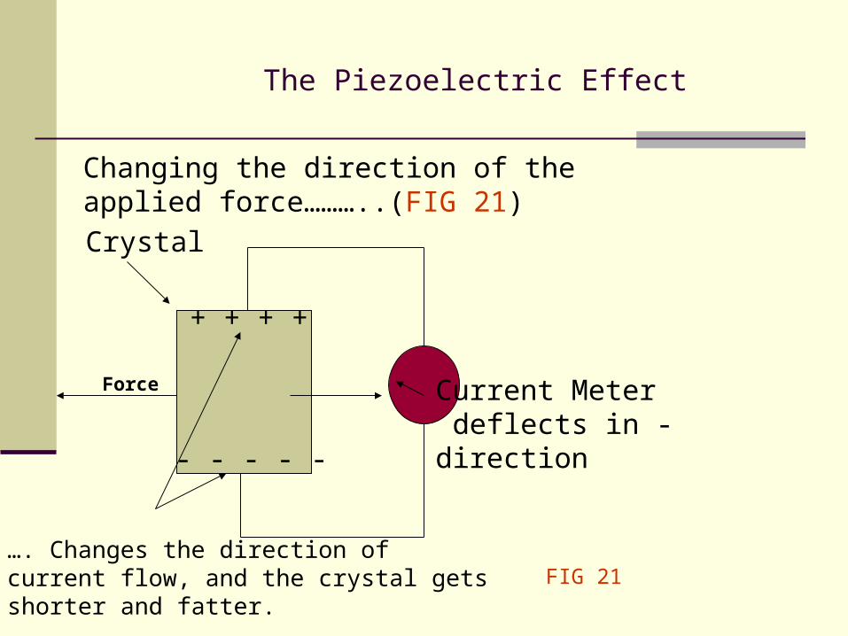
The Piezoelectric Effect
Crystal
Current Meter deflects in - direction
+ + + +
- - - - -
…. Changes the direction of current flow, and the crystal getsshorter and fatter.
Changing the direction of theapplied force………..(FIG 21)
Force
FIG 21
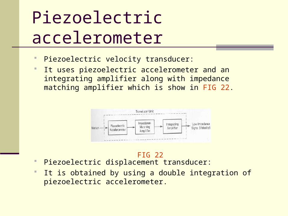
Piezoelectric accelerometer
Piezoelectric velocity transducer: It uses piezoelectric accelerometer and an integrating amplifier
along with impedance matching amplifier which is show in FIG 22.
Piezoelectric displacement transducer: It is obtained by using a double integration of piezoelectric
accelerometer.
FIG 22
Piezoelectric Sensor
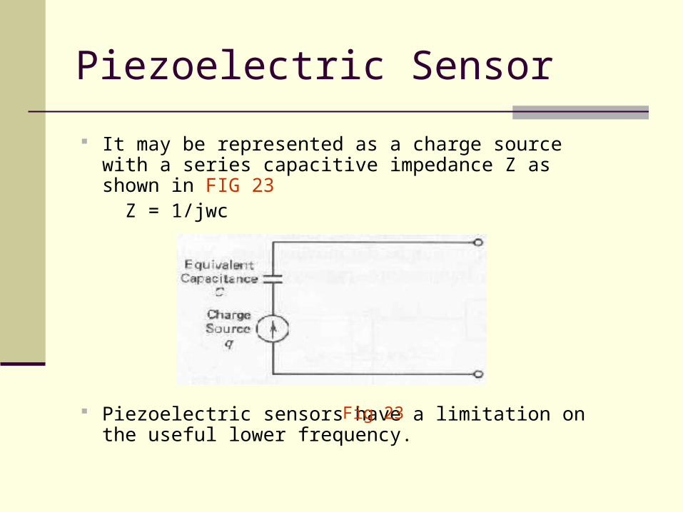
It may be represented as a charge source with a series capacitive impedance Z as shown in FIG 23
Z = 1/jwc
Piezoelectric sensors have a limitation on the useful lower frequency.
Fig 23
Piezoelectric accelerometer
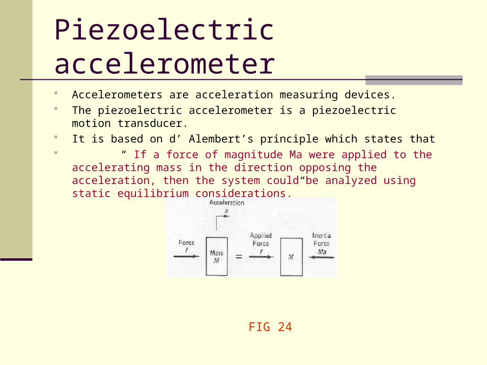
Accelerometers are acceleration measuring devices. The piezoelectric accelerometer is a piezoelectric motion transducer. It is based on d’ Alembert’s principle which states that “ If a force of magnitude Ma were applied to the accelerating mass in the
direction opposing the acceleration, then the system could be analyzed using static equilibrium considerations.”
FIG 24
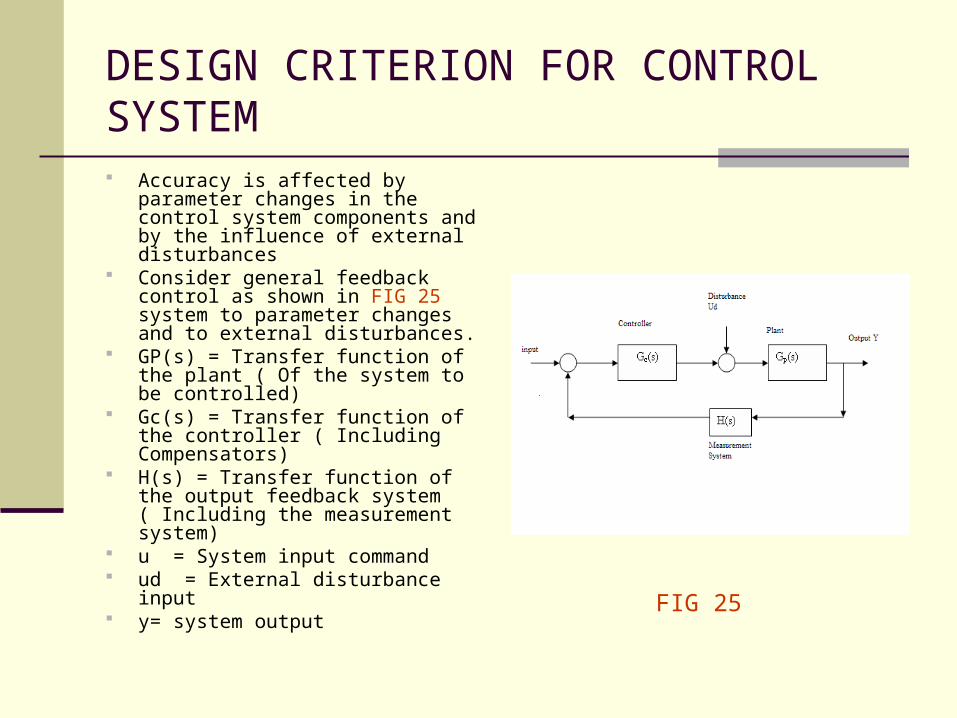
DESIGN CRITERION FOR CONTROL SYSTEM Accuracy is affected by parameter
changes in the control system components and by the influence of external disturbances
Consider general feedback control as shown in FIG 25 system to parameter changes and to external disturbances.
GP(s) = Transfer function of the plant ( Of the system to be controlled)
Gc(s) = Transfer function of the controller ( Including Compensators)
H(s) = Transfer function of the output feedback system ( Including the measurement system)
u = System input command ud = External disturbance input y= system output
FIG 25
After analyzing the feedback back control system we can stipulate the following design criterion for the system.
Make the measurement system (H) very accurate and stable
Increase the loop gain to reduce the sensitivity of the control system to changes in the plant and controller .
Increase the gain of GcH to reduce the influence of external disturbances
Conclusion
Analog Transducers play a very important part in insuring proper functioning of the systems.
They are simple, user friendly and reliable. But with increase in complexity and need for accuracy
in modern day plants use of analog transducers is very limited. Newly developed Digital and Optical Transducers are more apt for use in these plants.
References: Sensors and Actuators by C W Desilva. http://en.wikipedia.org/wiki/Sensor http://en.wikipedia.org/wiki/Eddy_current http://www.infoplease.com/ce6/sci/A0839004.
html http://www.encyclopedia.com/doc/1E1-
piezoele.html
Discussions
Discuss briefly Eddy current Proximity sensor.
How does linear displacement is measured using potentiometer ?
Explain how different motions are measured using Variable capacitance transducers ?

Questions and comments…