analogue instruments - matic.ru · pdf fileanalogue instruments standards en60051, vde 0410,...
TRANSCRIPT
Anal
ogue
ANALOGUE INSTRUMENTS
Analogue Instruments
GENERAL FEATURES ..................................................................................................................................... A.04FOR ALTERNATING CURRENT INSTRUMENTS
AMMETERS (INTERCHANGEABLE SCALE); DIRECT INPUT AMMETERS ..............................................A.05AMMETERS (mA) .........................................................................................................................................A.06VOLTMETERS (INTERCHANGEABLE SCALE); DIRECT INPUT VOLTMETERS ...................................... A.06DIMENSIONS AND CONNECTION DIAGRAMS ..........................................................................................A.07
AMMETERS WITH SWITCH (INTERCHANGEABLE SCALE) .....................................................................A.08VOLTMETERS WITH SWITCH .....................................................................................................................A.08DIMENSIONS AND CONNECTION DIAGRAMS ..........................................................................................A.09
MOVING COIL WITH CONVERTERAMMETERS AND VOLTMETERS (240º SCALE) .........................................................................................A.10DIMENSIONS AND CONNECTION DIAGRAMS ...........................................................................................A.11
MOVING COIL WITH RECTIFIERAMMETERS AND VOLTMETERS (90º SCALE) ...........................................................................................A.12AMMETERS AND VOLTMETERS (240º SCALE) .........................................................................................A.12DIMENSIONS AND CONNECTION DIAGRAMS ..........................................................................................A.13
RATED VALUE VOLTMETERS .............................................................................................................................A.14ELAPSED TIME METER .......................................................................................................................................A.15PHASE SEQUENCE INDICATORS .......................................................................................................................A.15INSTRUMENTS WITH CONTACTS ......................................................................................................................A.16BIMETALLIC INSTRUMENTS (POWER DEMAND METERS) .............................................................................A.17
BIMETALLIC AMMETERS (INTERCHANGEABLE SCALE) .........................................................................A.17BIMETALLIC AMMETERS WITH CONTACTS ..............................................................................................A.17
BIMETALLIC INSTRUMENTS + MOVING IRON ..................................................................................................A.18MAXIMUM DEMAND AMMETERS WITH MOVING IRON SYSTEM ............................................................A.18
MAXIMUM DEMAND AMMETERS WITH MOVING IRON SYSTEM AND CONTACTS .............................. A.18DIMENSIONS AND CONNECTION DIAGRAMS (BIMETAL) .......................................................................A.19
FOR DIRECT CURRENT INSTRUMENTSAMMETERS (INTERCHANGEABLE SCALE) .............................................................................................. A.20AMMETERS (µA, mA and A) (90º SCALE) ...................................................................................................A.20DIMENSIONS AND CONNECTION DIAGRAMS (90º SCALE) ....................................................................A.21
NON-ELECTRIC UNIT INDICATORS ....................................................................................................................A.23TEMPERATURE INDICATORS .............................................................................................................................A.24SPECIAL INSTRUMENTS, MOBILE EQUIPMENT (RAILWAYS) ........................................................................A.24SHUNTS (RESISTORS) ........................................................................................................................................A.25
REED FREQUENCY METERS ..............................................................................................................................A.26
POINTER FREQUENCY METERS ........................................................................................................................A.27DIMENSIONS AND CONNECTION DIAGRAMS ..................................................................................................A.28
ANALOGUE INSTRUMENTSCONTENTS
A.02

Anal
ogue
Analogue Instruments
CONTENTS
WATTMETERS AND VARMETERSELECTRONIC WATTMETERS .................................................................................................................... A.29ELECTRONIC VARMETERS .....................................................................................................................A.30DIMENSIONS AND CONNECTION DIAGRAMS ................................................................................A.31-32
WATTMETERS AND VARMETERS (INDUCTION SYSTEMS) ..................................................................A.33DIMENSIONS AND CONNECTION DIAGRAMS ........................................................................................A.33
PHASE METERSELECTRONIC PHASE METERS ...............................................................................................................A.34
DIMENSIONS AND CONNECTION DIAGRAMS ......................................................................................A.35PHASE METERS (INDUCTION SYSTEM) ...............................................................................................A.36DIMENSIONS AND CONNECTION DIAGRAMS ................................................................................A.36-37
RESISTOR BOXES .................................................................................................................................................A.38
SYNCHRONIZING INSTRUMENTSRELAYS
EQUIPMENT FOR VESSELS
MEASURING INSTRUMENTS FOR VESSELS (RECOMMENDATIONS) ......................................................A.40-41
FOR SYNCHRONIZING INSTRUMENTSDOUBLE VOLTMETERS .............................................................................................................................A.42DIFFERENTIAL VOLTMETERS ....................................................................................................................A.42DIMENSIONS AND CONNECTION DIAGRAMS ..........................................................................................A.42
DOUBLE FREQUENCY METERS (REEDS) ...............................................................................................A.43DIFFERENTIAL FREQUENCY METERS .......................................................................................................A.43DIMENSIONS AND CONNECTION DIAGRAMS ..........................................................................................A.43
SYNCHRONOSCOPES ...............................................................................................................................A.44CONNECTION DIAGRAM ...........................................................................................................................A.45LAMP SYNCHRONOSCOPE ........................................................................................................................A.46
SYNCHRONOSCOPE / DIGITAL SYNCHRONIZING RELAY ................................................................................A.47
SYNCHRONIZING EQUIPMENT ...............................................................................................................................A.48
REVERSE POWER RELAY ....................................................................................................................................A.49SYNCHRONISING RELAY ......................................................................................................................................A.50MAXIMUM CURRENT RELAY ....................................................................................................................................A.51MIN-MAX VOLTAGE AND FREQUENCY RELAY .................................................................................................A.52SEQUENCE METER / SEQUENCE RELAY WITH ALARM ...................................................................................A.46
INSULATION INDICATORS ....................................................................................................................................A.53RUDDER DEGREE INDICATORS FOR VESSELS ...............................................................................................A.54R.P.M. INDICATORS FOR VESSELS ....................................................................................................................A.54
VOLTAGE AND CURRENT SURVEILLANCE RELAY ..........................................................................................A.55
ANALOGUE INSTRUMENTS
A.03
Analogue Instruments
Standards EN60051, VDE 0410, BS-89, EN50081, EN50082, EN61010
Certifications TÜV CERT (ISO 9001-2000)VDE, DET NORSKE VERITAS, BUREAU VERITASGERMANISCHER LLOYD (relay)
Casings DIN 4370072x72, 96x96, 144x144MODULAR (for DIN rail)
Scales Full scale value, DIN 43701Scale division, DIN 43802
Pointers DIN 43802
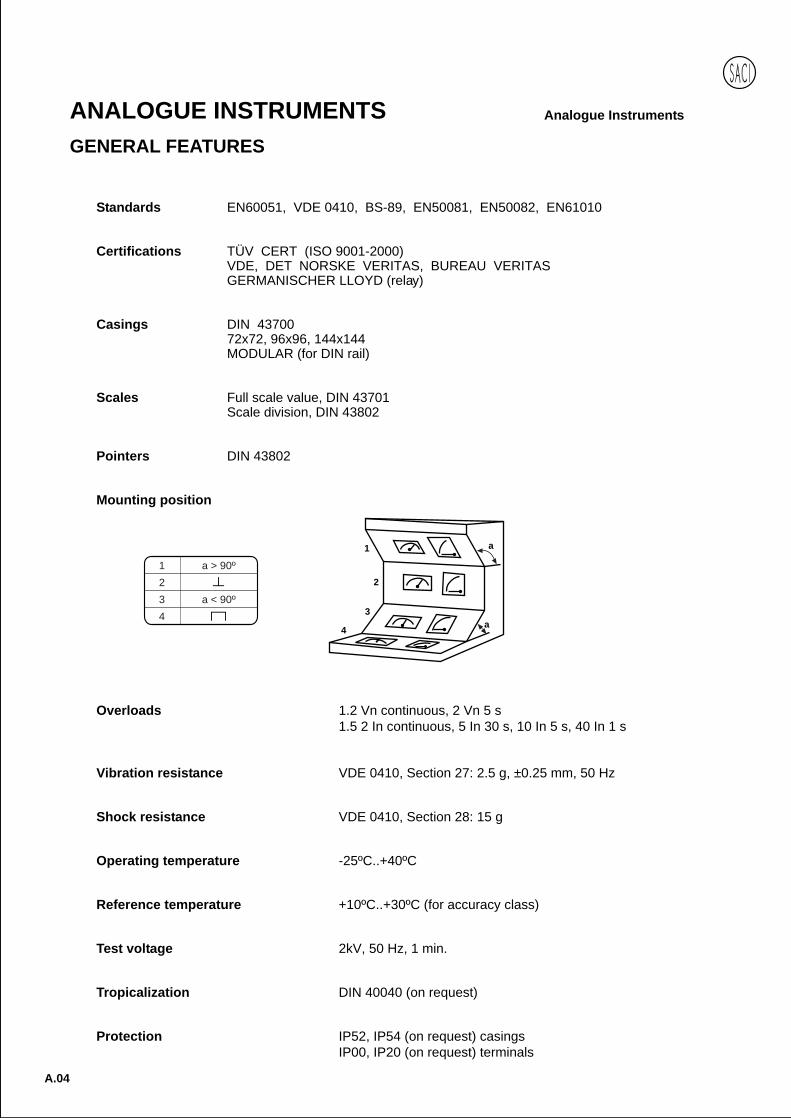
Mounting position
Overloads 1.2 Vn continuous, 2 Vn 5 s1.5 2 In continuous, 5 In 30 s, 10 In 5 s, 40 In 1 s
Vibration resistance VDE 0410, Section 27: 2.5 g, ±0.25 mm, 50 Hz
Shock resistance VDE 0410, Section 28: 15 g
Operating temperature -25ºC..+40ºC
Reference temperature +10ºC..+30ºC (for accuracy class)
Test voltage 2kV, 50 Hz, 1 min.
Tropicalization DIN 40040 (on request)
Protection IP52, IP54 (on request) casingsIP00, IP20 (on request) terminals
1
2
3
4a
a
1 a > 90º
2
3 a < 90º
4
A.04
ANALOGUE INSTRUMENTSGENERAL FEATURES

Anal
ogue
AMMETERS (INTERCHANGEABLE SCALE)
- Measuring range: 5A, 1A- Scale: 90º - Frequency: 15..100 Hz- Accuracy: 1.5 % - Burden: 0.4 VA
* IP20 protection
DIN RAIL
Model EC5VR EC5V EC4V EC3V EC4VP* EC3VP*
Dimensions mm 45x52,5 48x48 72x72 96x96 72x72 96x96
Approx.weight Kg. 0,25 0,09 0,20 0,25 0,20 0,25
A CT OPERATED AMMETERS (INTERCHANGEABLE SCALE)
Module X/5A or X/1A
Scales In 10; 15; 20; 25; 30; 40; 50; 60 or 75 A
and multiples
Module 2X/5A or 2X/1A
Scales 2xIn 10..20; 15..30; 20..40; 25..50; 30..60; 40..80; 50..100; 60..120 or 75..150 A
and multiples
Module 5X/5A or 5X/1A
Scales 5xIn 10..50; 15..75; 20..100; 25..125; 30..150; 40..200; 50..250; 60..300 or 75..375 A
and multiples
DIRECT INPUT AMMETERS
- Scale: 90º - Frequency: 15..100 Hz- Accuracy: 1.5 % - Burden: 0.3..1 VA
MEASURINGRANGE
DIN RAIL
* Maximum measuring range: 40 A, 40..80 A, 40..200 A** Maximum measuring range: 50 A, 50..100 A, 50..250 A
Model EC5VR* EC5V* EC4V EC3V EC2V ECb7** ECb3** ECb8**
Dimensions mm 45x52,5 48x48 72x72 96x96 144x144 80x64 105x80 130x100
Approx.weight Kg. 0,20 0,09 0,20 0,25 0,50 0,14 0,18 0,25
A DIRECT INPUT AMMETERS
In 1; 1,5; 2,5; 4; 5; 6; 10; 15; 20; 25; 30; 40; 50; 60; 75 or 100 A
2xIn 1..2; 1,5..3; 2,5..5; 4..8; 5..10; 6..12
10..20; 15..30; 20..40; 25..50; 30..60; 40..80; 50..100; 60..120; 75..150 or 100..200 A
5xIn 1..5; 1,5..7,5; 2,5..7,5; 4..20; 5..25; 6..30
10..50; 15..75; 20..100; 25..125; 30..150; 40..200; 50..250; 60..300; 75..375 or 100..500 A
ANALOGUE INSTRUMENTSMOVING IRONVoltage and alternating current. True efective value.
A.05
Analogue Instruments
A.06
ANALOGUE INSTRUMENTS Analogue Instruments
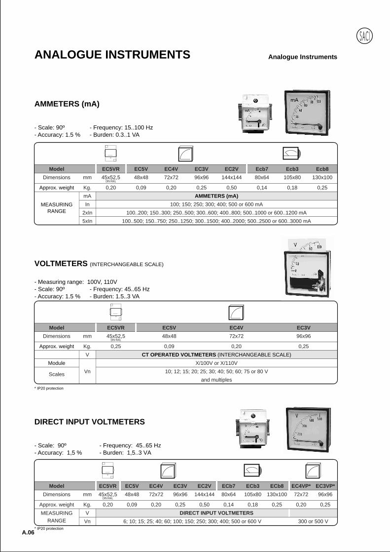
AMMETERS (mA)
- Scale: 90º - Frequency: 15..100 Hz- Accuracy: 1.5 % - Burden: 0.3..1 VA
Model EC5VR EC5V EC4V EC3V EC2V Ecb7 Ecb3 Ecb8
Dimensions mm 45x52,5 48x48 72x72 96x96 144x144 80x64 105x80 130x100
Approx. weight Kg. 0,20 0,09 0,20 0,25 0,50 0,14 0,18 0,25
mA AMMETERS (mA)
In 100; 150; 250; 300; 400; 500 or 600 mA
2xIn 100..200; 150..300; 250..500; 300..600; 400..800; 500..1000 or 600..1200 mA
5xIn 100..500; 150..750; 250..1250; 300..1500; 400..2000; 500..2500 or 600..3000 mA
MEASURINGRANGE
DIN RAIL
DIRECT INPUT VOLTMETERS
- Scale: 90º - Frequency: 45..65 Hz- Accuracy: 1,5 % - Burden: 1,5..3 VA
Model EC5VR EC5V EC4V EC3V EC2V ECb7 ECb3 ECb8 EC4VP* EC3VP*
Dimensions mm 45x52,5 48x48 72x72 96x96 144x144 80x64 105x80 130x100 72x72 96x96
Approx. weight Kg. 0,20 0,09 0,20 0,25 0,50 0,14 0,18 0,25 0,20 0,25
V DIRECT INPUT VOLTMETERS
Vn 6; 10; 15; 25; 40; 60; 100; 150; 250; 300; 400; 500 or 600 V 300 or 500 V
MEASURINGRANGE
DIN RAIL
* IP20 protection
VOLTMETERS (INTERCHANGEABLE SCALE)
- Measuring range: 100V, 110V- Scale: 90º - Frequency: 45..65 Hz- Accuracy: 1.5 % - Burden: 1.5..3 VA
* IP20 protection
DIN RAIL
Model EC5VR EC5V EC4V EC3V
Dimensions mm 45x52,5 48x48 72x72 96x96
Approx. weight Kg. 0,25 0,09 0,20 0,25
V CT OPERATED VOLTMETERS (INTERCHANGEABLE SCALE)
Module X/100V or X/110V
Scales Vn 10; 12; 15; 20; 25; 30; 40; 50; 60; 75 or 80 V
and multiples
Anal
ogue
ANALOGUE INSTRUMENTS
A.07
Analogue Instruments
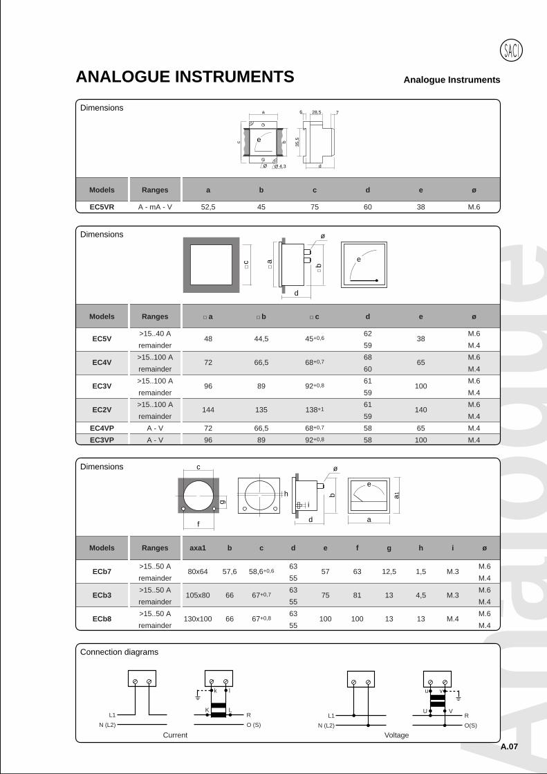
Models Ranges a b c d e ø
EC5V>15..40 A
48 44,5 45+0,662
38M.6
remainder 59 M.4
EC4V>15..100 A
72 66,5 68+0,768
65M.6
remainder 60 M.4
EC3V>15..100 A
96 89 92+0,861
100M.6
remainder 59 M.4
EC2V>15..100 A
144 135 138+161
140M.6
remainder 59 M.4
EC4VP A - V 72 66,5 68+0,7 58 65 M.4
EC3VP A - V 96 89 92+0,8 58 100 M.4
ec
d
b
ø
a
Models Ranges axa1 b c d e f g h i ø
ECb7>15..50 A
80x64 57,6 58,6+0,663
57 63 12,5 1,5 M.3M.6
remainder 55 M.4
ECb3>15..50 A
105x80 66 67+0,763
75 81 13 4,5 M.3M.6
remainder 55 M.4
ECb8>15..50 A
130x100 66 67+0,863
100 100 13 13 M.4M.6
remainder 55 M.4
e
ad
b
i
ø
h
c
f
g
a1
k l
LKR
O (S)
L1
N (L2)
Connection diagrams
e
a
c b
35,5
6 728,5
Ø 4,3Ø d
Models Ranges a b c d e ø
EC5VR A - mA - V 52,5 45 75 60 38 M.6
Voltage
L1
N (L2)
R
O(S)
U V
vu
Current
Dimensions
Dimensions
Dimensions
A.08
Analogue InstrumentsANALOGUE INSTRUMENTS
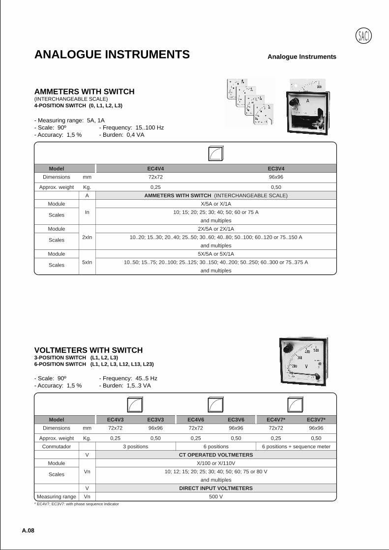
Model EC4V4 EC3V4
Dimensions mm 72x72 96x96
Approx. weight Kg. 0,25 0,50
A AMMETERS WITH SWITCH (INTERCHANGEABLE SCALE)
Module X/5A or X/1A
Scales In 10; 15; 20; 25; 30; 40; 50; 60 or 75 A
and multiples
Module 2X/5A or 2X/1A
Scales 2xIn 10..20; 15..30; 20..40; 25..50; 30..60; 40..80; 50..100; 60..120 or 75..150 A
and multiples
Module 5X/5A or 5X/1A
Scales 5xIn 10..50; 15..75; 20..100; 25..125; 30..150; 40..200; 50..250; 60..300 or 75..375 A
and multiples
AMMETERS WITH SWITCH(INTERCHANGEABLE SCALE)4-POSITION SWITCH (0, L1, L2, L3)
- Measuring range: 5A, 1A- Scale: 90º - Frequency: 15..100 Hz- Accuracy: 1,5 % - Burden: 0,4 VA
Model EC4V3 EC3V3 EC4V6 EC3V6 EC4V7* EC3V7*
Dimensions mm 72x72 96x96 72x72 96x96 72x72 96x96
Approx. weight Kg. 0,25 0,50 0,25 0,50 0,25 0,50
Conmutador 3 positions 6 positions 6 positions + sequence meter
V CT OPERATED VOLTMETERS
Module X/100 or X/110V
Scales Vn 10; 12; 15; 20; 25; 30; 40; 50; 60; 75 or 80 V
and multiples
V DIRECT INPUT VOLTMETERS
Measuring range Vn 500 V
VOLTMETERS WITH SWITCH3-POSITION SWITCH (L1, L2, L3)6-POSITION SWITCH (L1, L2, L3, L12, L13, L23)
- Scale: 90º - Frequency: 45..5 Hz- Accuracy: 1,5 % - Burden: 1,5..3 VA
* EC4V7; EC3V7: with phase sequence indicator

Anal
ogue
A.09
Analogue InstrumentsANALOGUE INSTRUMENTS
Voltage
R
S
T
0
L1
L2
L3
N
R S T 0(L1) (L2) (L3) (N)
K L
k l
K L
k l
K L
k l
Current
R
S
T
Mp
L1
L2
L3
N
R S T 0(L1) (L2) (L3) (N)
Connection diagrams
Models Ranges a b c d e ø
EC4V3
EC4V6 V 72 66,5 68+0,7 68 65 M.4
EC4V7
EC3V3
EC3V6 V 96 89 92+0,8 67 100 M.4
EC3V7
EC4V4 A 72 66,5 68+0,7 68 65 M.4
EC3V4 A 96 89 92+0,8 67 100 M.4
ec
d
b
ø
a
17Dimensions
A.10
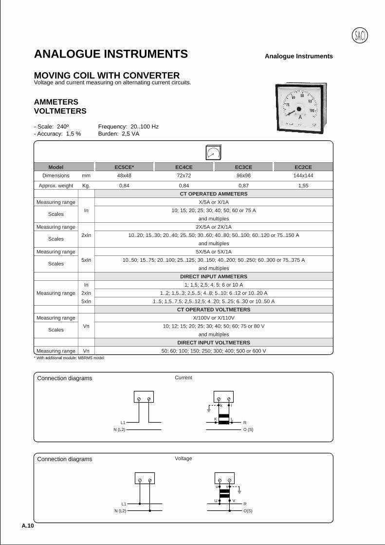
Analogue InstrumentsANALOGUE INSTRUMENTS
MOVING COIL WITH CONVERTERVoltage and current measuring on alternating current circuits.
AMMETERSVOLTMETERS
- Scale: 240º Frequency: 20..100 Hz- Accuracy: 1,5 % Burden: 2,5 VA
* With additional module: MBRMS model
Model EC5CE* EC4CE EC3CE EC2CE
Dimensions mm 48x48 72x72 96x96 144x144
Approx. weight Kg. 0,84 0,84 0,87 1,55
CT OPERATED AMMETERS
Measuring range X/5A or X/1A
ScalesIn 10; 15; 20; 25; 30; 40; 50; 60 or 75 A
and multiples
Measuring range 2X/5A or 2X/1A
Scales2xIn 10..20; 15..30; 20..40; 25..50; 30..60; 40..80; 50..100; 60..120 or 75..150 A
and multiples
Measuring range 5X/5A or 5X/1A
Scales5xIn 10..50; 15..75; 20..100; 25..125; 30..150; 40..200; 50..250; 60..300 or 75..375 A
and multiples
DIRECT INPUT AMMETERS
In 1; 1,5; 2,5; 4; 5; 6 or 10 A
Measuring range 2xIn 1..2; 1,5..3; 2,5..5; 4..8; 5..10; 6..12 or 10..20 A
5xIn 1..5; 1,5..7,5; 2,5..12,5; 4..20; 5..25; 6..30 or 10..50 A
CT OPERATED VOLTMETERS
Measuring range X/100V or X/110V
ScalesVn 10; 12; 15; 20; 25; 30; 40; 50; 60; 75 or 80 V
and multiples
DIRECT INPUT VOLTMETERS
Measuring range Vn 50; 60; 100; 150; 250; 300; 400; 500 or 600 V
k l
LKR
O (S)
L1
N (L2)
Current
Voltage
L1
N (L2)
R
O(S)
U V
vu
Connection diagrams
Connection diagrams

Anal
ogue
A.11
Analogue InstrumentsANALOGUE INSTRUMENTS
Models Range a b c d e ø
EC5CE A - V 48 44,5 45+0,6 83 72 M.4
EC4CE A - V 72 66,5 68+0,7 88 101 M.4
EC3CE A - V 96 89 92+0,8 74 140 M.4
EC2CE A - V 144 135 138+1 88 220 M.4
c a
d
b
ø
e
Dimensions
105
90 93 45 62
2548
58
Dimensions
Weight = 0,240Plug-in connectors
DIN rail MBRMS additional module
A.12
Analogue InstrumentsANALOGUE INSTRUMENTS
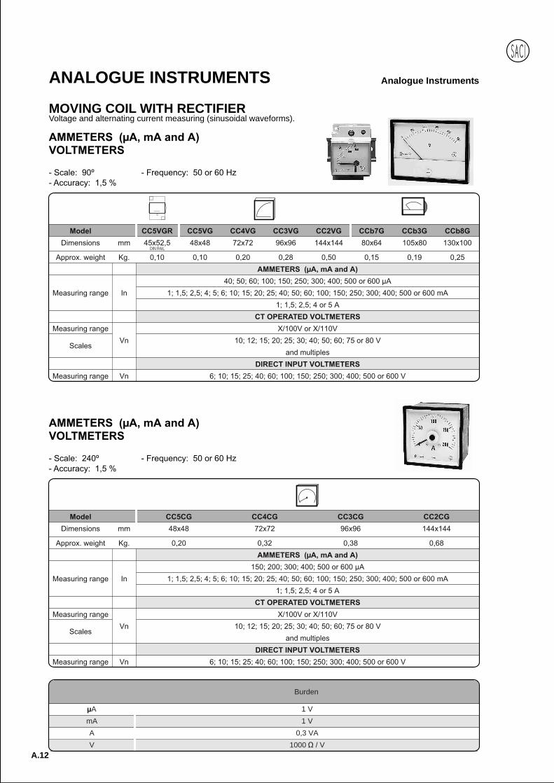
MOVING COIL WITH RECTIFIERVoltage and alternating current measuring (sinusoidal waveforms).
DIN RAIL
Burden
A 1 V
mA 1 V
A 0,3 VA
V 1000 / V

Anal
ogue
A.13
Analogue InstrumentsANALOGUE INSTRUMENTS
e
a
c b
35,5
6 728,5
Ø 4,3Ø d
ec
d
b
ø
a
e
ad
b
i
ø
h
c
f
g
a1
c a
d
b
ø
e
k l
LKRO (S)
L1N (L2)
Current Voltage
L1N (L2)
RO(S)
U V
vu
Dimensions
Connection diagrams
Dimensions
Dimensions
Dimensions
A.14
Analogue InstrumentsANALOGUE INSTRUMENTS
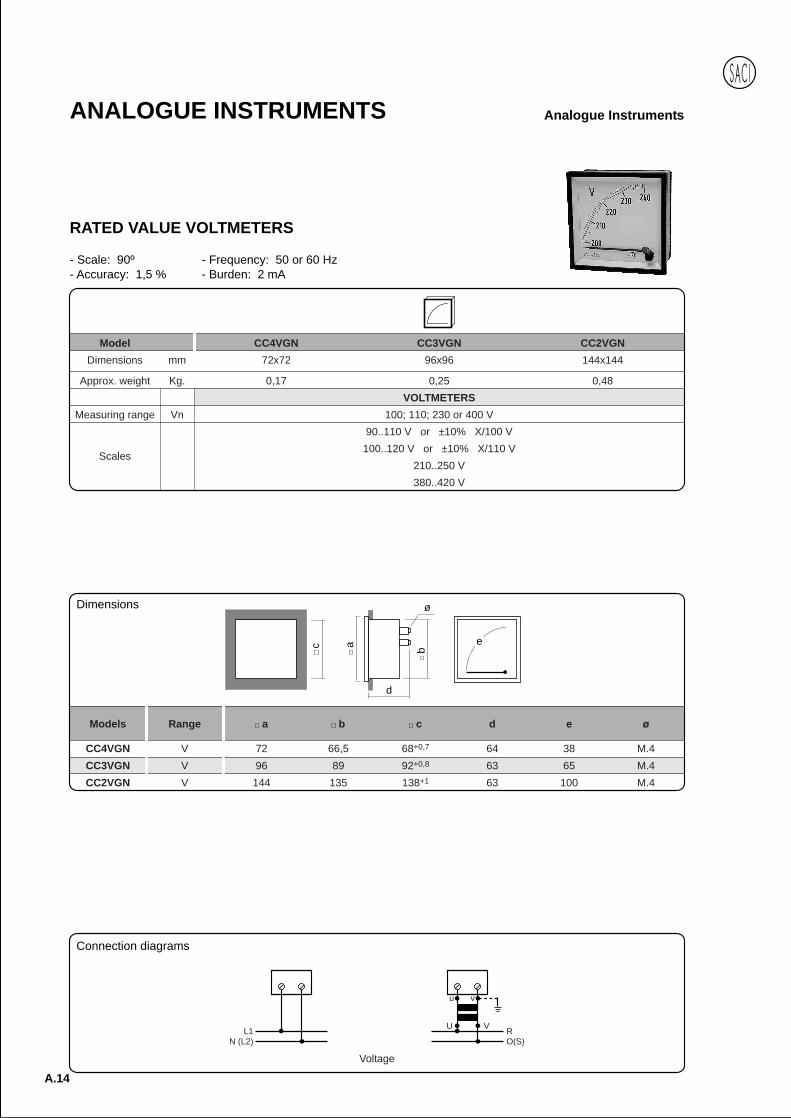
RATED VALUE VOLTMETERS
- Scale: 90º - Frequency: 50 or 60 Hz- Accuracy: 1,5 % - Burden: 2 mA
Model CC4VGN CC3VGN CC2VGN
Dimensions mm 72x72 96x96 144x144
Approx. weight Kg. 0,17 0,25 0,48
VOLTMETERS
Measuring range Vn 100; 110; 230 or 400 V
90..110 V or ±10% X/100 V
Scales100..120 V or ±10% X/110 V
210..250 V
380..420 V
Models Range a b c d e ø
CC4VGN V 72 66,5 68+0,7 64 38 M.4
CC3VGN V 96 89 92+0,8 63 65 M.4
CC2VGN V 144 135 138+1 63 100 M.4
ec
d
b
ø
a
Voltage
L1N (L2)
RO(S)
U V
vu
Connection diagrams
Dimensions

Anal
ogue
A.15
Analogue InstrumentsANALOGUE INSTRUMENTSANALOGUE INSTRUMENTS
ELAPSED TIME METEROperating time control of machines and equipment
- Meter: mechanical, 7 digits (99999.99)- Voltage (Vn): 110, 230, 400 V - Burden: 10 mA- Voltage range: ±10 % Vn - Frequency: 50 or 60 Hz
Model HC5 HC4 HC3
Dimensions mm 48x48 72x72 96x96
Approx. weight Kg. 0,06 0,14 0,175
- Voltage (Vn): 100..600 V - Burden: 1,2 VA- Frequency: 50 or 60 Hz
Model IRC4E IRC3E
Dimensions mm 72x72 96x96
Approx. weight Kg. 0,20 0,26
Models Range a b c d ø
HC5 110÷400 48 44,5 45,2+0,6 34 M.3
HC4 110÷400 72 66,5 68+0,7 60 M.3
HC3 110÷400 96 89 92+0,8 60 M.3
c
d
bø
a
Models Range a b c d ø
IRC4E 100÷600 V 72 66,5 68+0,7 79 M.4
IRC3E 100÷600 V 96 89 92+0,8 78 M.4
c
d
b
ø
a
RO(S)
U V
vu
L1N (L2)
L1N (L2)
RO(S)
R
S
T
L1
L2
L3
R S TL1 L2 L3
ANALOGUE INSTRUMENTS
PHASE SEQUENCE INDICATORSPhase sequence detection on a three-phase system.
Connection diagramsDimensions
Connection diagramsDimensions
A.16
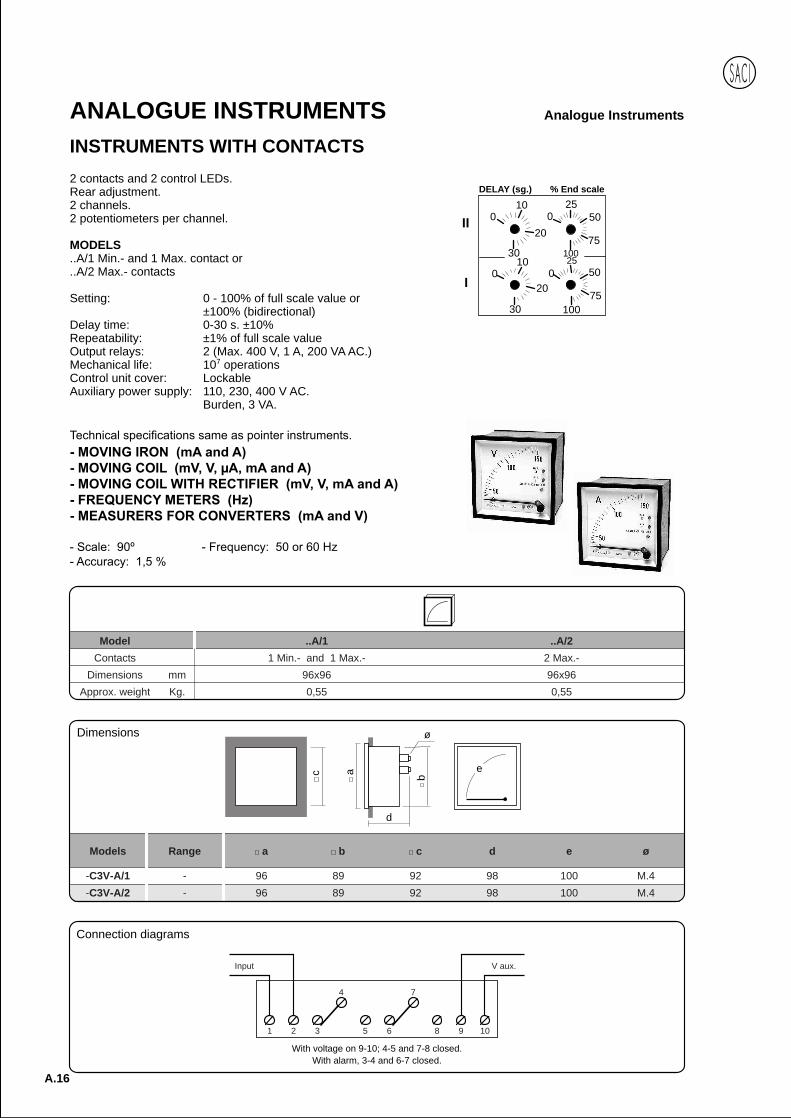
Analogue InstrumentsANALOGUE INSTRUMENTSINSTRUMENTS WITH CONTACTS
010
20
30
010
20
30
025
50
75100
025
50
75100
DELAY (sg.) % End scale
II
I
Model ..A/1 ..A/2
Contacts 1 Min.- and 1 Max.- 2 Max.-
Dimensions mm 96x96 96x96
Approx. weight Kg. 0,55 0,55
With voltage on 9-10; 4-5 and 7-8 closed.With alarm, 3-4 and 6-7 closed.
2 contacts and 2 control LEDs.Rear adjustment.2 channels.2 potentiometers per channel.
MODELS..A/1 Min.- and 1 Max. contact or..A/2 Max.- contacts
Setting: 0 - 100% of full scale value or±100% (bidirectional)
Delay time: 0-30 s. ±10%Repeatability: ±1% of full scale valueOutput relays: 2 (Max. 400 V, 1 A, 200 VA AC.)Mechanical life: 107 operationsControl unit cover: LockableAuxiliary power supply: 110, 230, 400 V AC.
Burden, 3 VA.
Connection diagrams
Models Range a b c d e ø
-C3V-A/1 - 96 89 92 98 100 M.4
-C3V-A/2 - 96 89 92 98 100 M.4
ec
d
b
ø
a
Dimensions
1 2 3 5 6 8 9 10
V aux.
4 7
Input
Anal
ogue
A.17
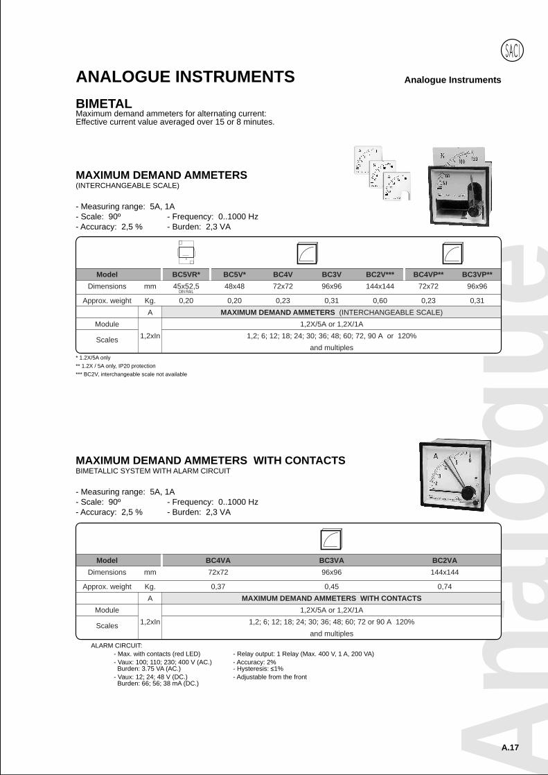
Analogue InstrumentsANALOGUE INSTRUMENTSBIMETALMaximum demand ammeters for alternating current:Effective current value averaged over 15 or 8 minutes.
ALARM CIRCUIT:- Max. with contacts (red LED) - Relay output: 1 Relay (Max. 400 V, 1 A, 200 VA)- Vaux: 100; 110; 230; 400 V (AC.) - Accuracy: 2% Burden: 3.75 VA (AC.) - Hysteresis: 1%- Vaux: 12; 24; 48 V (DC.) - Adjustable from the front Burden: 66; 56; 38 mA (DC.)
Model BC4VA BC3VA BC2VA
Dimensions mm 72x72 96x96 144x144
Approx. weight Kg. 0,37 0,45 0,74
A MAXIMUM DEMAND AMMETERS WITH CONTACTS
Module 1,2X/5A or 1,2X/1A
Scales 1,2xIn 1,2; 6; 12; 18; 24; 30; 36; 48; 60; 72 or 90 A 120%
and multiples
MAXIMUM DEMAND AMMETERS WITH CONTACTSBIMETALLIC SYSTEM WITH ALARM CIRCUIT
- Measuring range: 5A, 1A- Scale: 90º - Frequency: 0..1000 Hz- Accuracy: 2,5 % - Burden: 2,3 VA
Model BC5VR* BC5V* BC4V BC3V BC2V*** BC4VP** BC3VP**
Dimensions mm 45x52,5 48x48 72x72 96x96 144x144 72x72 96x96
Approx. weight Kg. 0,20 0,20 0,23 0,31 0,60 0,23 0,31
A MAXIMUM DEMAND AMMETERS (INTERCHANGEABLE SCALE)
Module 1,2X/5A or 1,2X/1A
Scales 1,2xIn 1,2; 6; 12; 18; 24; 30; 36; 48; 60; 72, 90 A or 120%
and multiples
MAXIMUM DEMAND AMMETERS(INTERCHANGEABLE SCALE)
- Measuring range: 5A, 1A- Scale: 90º - Frequency: 0..1000 Hz- Accuracy: 2,5 % - Burden: 2,3 VA
* 1.2X/5A only** 1.2X / 5A only, IP20 protection*** BC2V, interchangeable scale not available
DIN RAIL
A.18
Analogue InstrumentsANALOGUE INSTRUMENTS
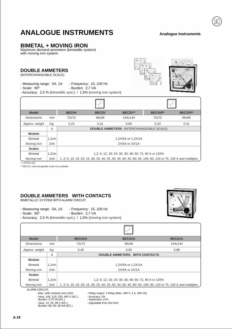
BIMETAL + MOVING IRONMaximum demand ammeters (bimetallic system)with moving iron system.
ALARM CIRCUIT:- Max. with contacts (red LED) - Relay output: 1 Relay (Max. 400 V, 1 A, 200 VA)- Vaux: 100; 110; 230; 400 V (AC.) - Accuracy: 2% Burden: 3.75 VA (AC.) - Hysteresis: 1%- Vaux: 12; 24; 48 V (DC.) - Adjustable from the front Burden: 66; 56; 38 mA (DC.)
DOUBLE AMMETERS WITH CONTACTSBIMETALLIC SYSTEM WITH ALARM CIRCUIT
- Measuring range: 5A, 1A - Frequency: 15..100 Hz- Scale: 90º - Burden: 2,7 VA- Accuracy: 2,5 % (bimetallic syst.) / 1,5% (moving iron system)
Model BEC4VA BEC3VA BEC2VA
Dimensions mm 72x72 96x96 144x144
Approx. weight Kg. 0,40 0,50 0,88
A DOUBLE AMMETERS WITH CONTACTS
Module
Bimetal 1,2xIn 1,2X/5A or 1,2X/1A
Moving iron 2xIn 2X/5A or 2X/1A
Scales
Bimetal 1,2xIn 1,2; 6; 12; 18; 24; 30; 36; 48; 60; 72, 90 A or 120%
Moving iron 2xIn 1..2; 5..10; 10..20; 15..30; 20..40; 25..50; 30..60; 40..80; 50..100; 60..120 or 75..150 A and multiples
DOUBLE AMMETERS(INTERCHANGEABLE SCALE)
- Measuring range: 5A, 1A - Frequency: 15..100 Hz- Scale: 90º - Burden: 2,7 VA- Accuracy: 2,5 % (bimetallic syst.) / 1,5% (moving iron system)
Model BEC4V BEC3V BEC2V** BEC4VP* BEC3VP*
Dimensions mm 72x72 96x96 144x144 72x72 96x96
Approx. weight Kg. 0,23 0,31 0,60 0,23 0,31
A DOUBLE AMMETERS (INTERCHANGEABLE SCALE)
Module
Bimetal 1,2xIn 1,2X/5A or 1,2X/1A
Moving iron 2xIn 2X/5A or 2X/1A
Scales
Bimetal 1,2xIn 1,2; 6; 12; 18; 24; 30; 36; 48; 60; 72, 90 A or 120%
Moving iron 2xIn 1..2; 5..10; 10..20; 15..30; 20..40; 25..50; 30..60; 40..80; 50..100; 60..120 or 75..150 A and multiples* 1.2X/5A only** BEC2V, interchangeable scale not available
Anal
ogue
A.19
Analogue InstrumentsANALOGUE INSTRUMENTS
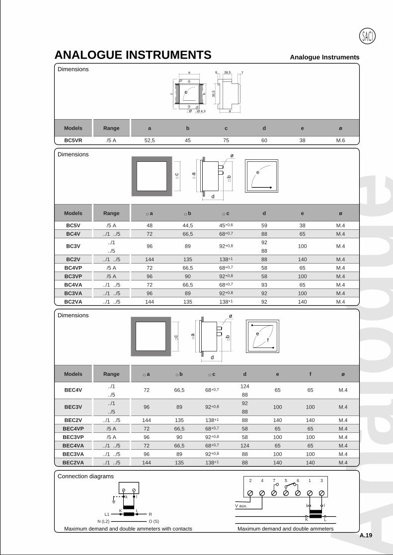
Models Range a b c d e ø
BC5V /5 A 48 44,5 45+0,6 59 38 M.4
BC4V ../1 ../5 72 66,5 68+0,7 88 65 M.4
BC3V../1
96 89 92+0,892
100 M.4../5 88
BC2V ../1 ../5 144 135 138+1 88 140 M.4
BC4VP /5 A 72 66,5 68+0,7 58 65 M.4
BC3VP /5 A 96 90 92+0,8 58 100 M.4
BC4VA ../1 ../5 72 66,5 68+0,7 93 65 M.4
BC3VA ../1 ../5 96 89 92+0,8 92 100 M.4
BC2VA ../1 ../5 144 135 138+1 92 140 M.4
ec
d
b
ø
a
Dimensions
Maximum demand and double ammeters
k l
LKR
O (S)
L1
N (L2)
Maximum demand and double ammeters with contacts
e
a
c b
35,5
6 728,5
Ø 4,3Ø d
Models Range a b c d e ø
BC5VR /5 A 52,5 45 75 60 38 M.6
Models Range a b c d e f ø
BEC4V../1
72 66,5 68+0,7124
65 65 M.4../5 88
BEC3V../1
96 89 92+0,892
100 100 M.4../5 88
BEC2V ../1 ../5 144 135 138+1 88 140 140 M.4
BEC4VP /5 A 72 66,5 68+0,7 58 65 65 M.4
BEC3VP /5 A 96 90 92+0,8 58 100 100 M.4
BEC4VA ../1 ../5 72 66,5 68+0,7 124 65 65 M.4
BEC3VA ../1 ../5 96 89 92+0,8 88 100 100 M.4
BEC2VA ../1 ../5 144 135 138+1 88 140 140 M.4
ef
a
d
b
ø
c
V aux.
2 4 7 5
K L
k l
6 1 3Connection diagrams
Dimensions
Dimensions

A.20
Analogue InstrumentsANALOGUE INSTRUMENTS
MOVING COILVoltage and current measuring on direct current circuits.
Model CC5VR CC5V CC4V CC3V CC4VP* CC3VP*
Dimensions mm 45x52,5 48x48 72x72 96x96 72x72 96x96
Approx. weight Kg. 0,10 0,09 0,21 0,28 0,21 0,28
AMMETERS (INTERCHANGEABLE SCALE)
Module Vn X/60 mV or X/150 mV
Scales In1; 1,5; 2,5; 4; 5; 6; 10; 15; 20; 25; 30; 40; 50; 60; 80 or 100 A
and multiples
AMMETERS (INTERCHANGEABLE SCALE)Via resistors (Shunt)
- Scale: 90º - Measuring range: 60 mV, 150 mV- Accuracy: 1,5 % - Burden: 60 - 150
* IP20 protection
DIN RAIL
MEASURINGRANGE
DIN RAIL
* Up to 40 A
Anal
ogue
A.21
Analogue InstrumentsANALOGUE INSTRUMENTS
VoltageCurrent
+
-
+
-
+
-
+
+
+Connection diagrams
e
a
c b
35,5
6 728,5
Ø 4,3Ø d
Dimensions
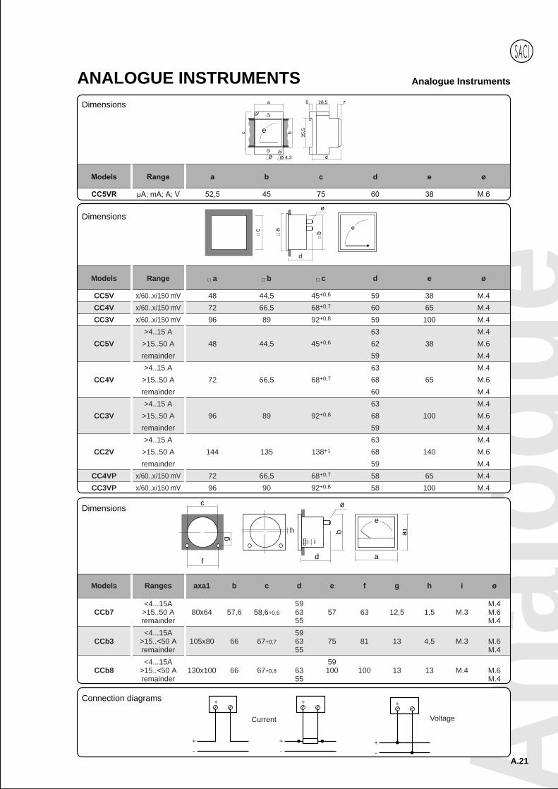
Models Range a b c d e ø
CC5V x/60..x/150 mV 48 44,5 45+0,6 59 38 M.4
CC4V x/60..x/150 mV 72 66,5 68+0,7 60 65 M.4
CC3V x/60..x/150 mV 96 89 92+0,8 59 100 M.4
>4..15 A 63 M.4
CC5V >15..50 A 48 44,5 45+0,6 62 38 M.6
remainder 59 M.4
>4..15 A 63 M.4
CC4V >15..50 A 72 66,5 68+0,7 68 65 M.6
remainder 60 M.4
>4..15 A 63 M.4
CC3V >15..50 A 96 89 92+0,8 68 100 M.6
remainder 59 M.4
>4..15 A 63 M.4
CC2V >15..50 A 144 135 138+1 68 140 M.6
remainder 59 M.4
CC4VP x/60..x/150 mV 72 66,5 68+0,7 58 65 M.4
CC3VP x/60..x/150 mV 96 90 92+0,8 58 100 M.4
ecd
b
ø
a
Dimensions
e
ad
b
i
ø
h
c
f
g
a1
Dimensions
Models Ranges axa1 b c d e f g h i ø
<4...15A 59 M.4CCb7 >15..50 A 80x64 57,6 58,6+0,6 63 57 63 12,5 1,5 M.3 M.6
remainder 55 M.4
<4...15A 59CCb3 >15..<50 A 105x80 66 67+0,7 63 75 81 13 4,5 M.3 M.6
remainder 55 M.4
<4...15A 59CCb8 >15..<50 A 130x100 66 67+0,8 63 100 100 13 13 M.4 M.6
remainder 55 M.4
A.22
Analogue InstrumentsANALOGUE INSTRUMENTS
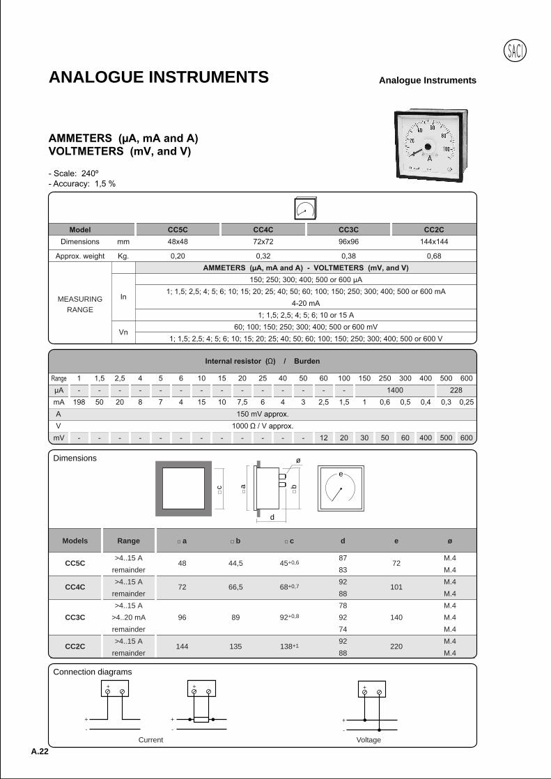
Models Range a b c d e ø
CC5C>4..15 A
48 44,5 45+0,687
72M.4
remainder 83 M.4
CC4C>4..15 A
72 66,5 68+0,792
101M.4
remainder 88 M.4
>4..15 A 78 M.4
CC3C >4..20 mA 96 89 92+0,8 92 140 M.4
remainder 74 M.4
CC2C>4..15 A
144 135 138+192
220M.4
remainder 88 M.4
c a
d
b
ø
e
Dimensions
MEASURINGRANGE
VoltageCurrent
+
-
+
+
-
+
-
+
+
Connection diagrams
Anal
ogue
A.23
Analogue InstrumentsANALOGUE INSTRUMENTS
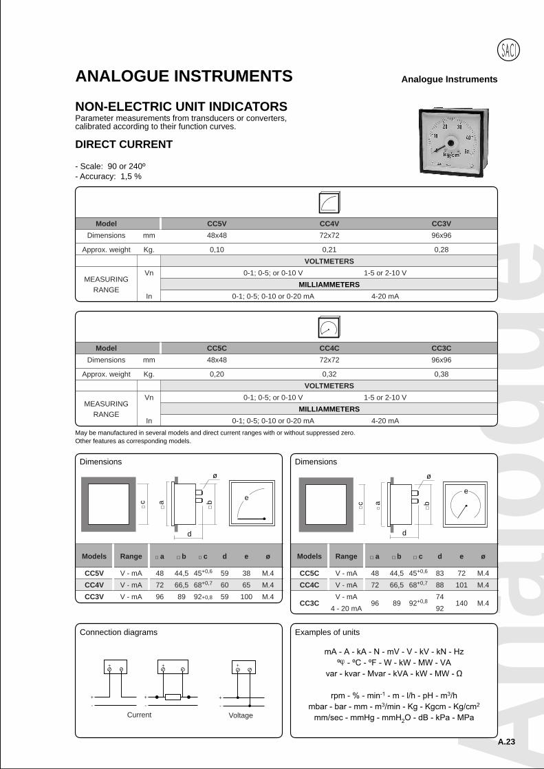
NON-ELECTRIC UNIT INDICATORSParameter measurements from transducers or converters,calibrated according to their function curves.
Model CC5V CC4V CC3V
Dimensions mm 48x48 72x72 96x96
Approx. weight Kg. 0,10 0,21 0,28
VOLTMETERS
Vn 0-1; 0-5; or 0-10 V 1-5 or 2-10 V
MILLIAMMETERS
In 0-1; 0-5; 0-10 or 0-20 mA 4-20 mA
DIRECT CURRENT
- Scale: 90 or 240º- Accuracy: 1,5 %
Model CC5C CC4C CC3C
Dimensions mm 48x48 72x72 96x96
Approx. weight Kg. 0,20 0,32 0,38
VOLTMETERS
Vn 0-1; 0-5; or 0-10 V 1-5 or 2-10 V
MILLIAMMETERS
In 0-1; 0-5; 0-10 or 0-20 mA 4-20 mA
May be manufactured in several models and direct current ranges with or without suppressed zero.Other features as corresponding models.
Connection diagrams
Voltage
+
-
+
Current
+
+
-
+
-
+
Models Range a b c d e ø
CC5C V - mA 48 44,5 45+0,6 83 72 M.4
CC4C V - mA 72 66,5 68+0,7 88 101 M.4
CC3CV - mA
96 89 92+0,874
140 M.44 - 20 mA 92
c a
d
b
ø
Dimensions
c a
d
b
ø
Models Range a b c d e ø
CC5V V - mA 48 44,5 45+0,6 59 38 M.4
CC4V V - mA 72 66,5 68+0,7 60 65 M.4
CC3V V - mA 96 89 92+0,8 59 100 M.4
Dimensions
Examples of units
ee
MEASURINGRANGE
MEASURINGRANGE

A.24
Analogue InstrumentsANALOGUE INSTRUMENTS
TEMPERATURE INDICATORSTemperature measuring via thermocouples or thermoresistances.
SPECIAL EXECUTIONS: MOBILE INSTRUMENTSMoving coil Instrument for mobile equipment (railways, tractor).
Measuring range and scales: please enquire.Scale: 240º Black scaleAccuracy: 1.5% Vaux: 12 or 24 V (DC.)Shock resistance: 15 g Vibration resistance: 10..55 HzWhite or yellow pointer, numbering and division
Ø79
,5
3567,54,5
107Ø 85,5
97
Dimensions
- Scale: 90º - Accuracy: ±1,5 %
The instrument indicates the temperature difference between the thermocouple welding point and the connection point of the two thermocouple elementswith the instrument interconnection line. If, in this last connection point, the temperature is 20° higher than the instrument calibration point, then asuitable correction line in each thermocouple is necessary.The instrument is calibrated according to the thermometric resistance boards. The 2 or 3 wire connection must be specified.
Model CC4V CC3V
Dimensions mm 72x72 96x96
Approx. weight Kg. 0,20 0,26
TEMPERATURE INDICATORS - DIN THERMOCOUPLE
Type J K E T S(Fe-Const.) (Chr-Alu) (Chr-Const.) (Cu-Const.) (Pt-PtRh)
Scales 20-400º 20-600º 20-900º 20-600º 20-900º 20-1200º 20-1000º 20-400º 20-1200º 20-1600º
Ranges 20,83 32,08 50,86 24,10 36,53 48,03 75,16 20,08 11,83 16,66
TEMPERATURE INDICATORS - THERMORESISTANCES
Type Pt-100 DIN NI-100 DIN
Scales 0-100º 0-150º 0-100º 0-150º
Vaux V12, 24, 48 or 110 V D.C. 12, 24, 48 or 110 V D.C.
- 110, 230 or 400 V A.C.
Models Ranges a b c d e ø
CC4V V 72 66,5 68+0,7 60 65 M.4
CC3V V 96 89 92+0,8 59 100 M.4
ec
d
b
ø
a
Connection diagrams
Vaux. Vaux.
+
+ -
DIN thermocouple
Thermoresistances
Dimensions
Anal
ogue
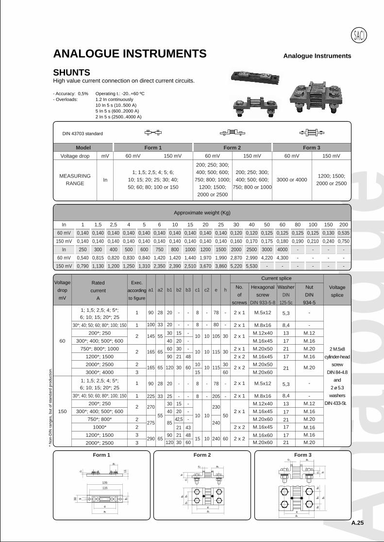
ANALOGUE INSTRUMENTSSHUNTSHigh value current connection on direct current circuits.
Approximate weight (Kg)
In 1 1,5 2,5 4 5 6 10 15 20 25 30 40 50 60 80 100 150 200
60 mV 0,140 0,140 0,140 0,140 0,140 0,140 0,140 0,140 0,140 0,140 0,120 0,120 0,125 0,125 0,125 0,125 0,130 0,535
150 mV 0,140 0,140 0,140 0,140 0,140 0,140 0,140 0,140 0,140 0,140 0,160 0,170 0,175 0,180 0,190 0,210 0,240 0,750
In 250 300 400 500 600 750 800 1000 1200 1500 2000 2500 3000 4000 - - - -
60 mV 0,540 0,815 0,820 0,830 0,840 1,420 1,420 1,440 1,970 1,990 2,870 2,990 4,220 4,300 - - - -
150 mV 0,790 1,130 1,200 1,250 1,310 2,350 2,390 2,510 3,670 3,860 5,220 5,530 - - - - - -
- Accuracy: 0,5% Operating t.: -20..+60 ºC- Overloads: 1.2 In continuously
10 In 5 s (10..500 A)5 In 5 s (600..2000 A)2 In 5 s (2500..4000 A)
MEASURINGRANGE
Model Form 1 Form 2 Form 3
60 mV 150 mV 60 mV 150 mV 60 mV 150 mV
1; 1,5; 2,5; 4; 5; 6;10; 15; 20; 25; 30; 40;50; 60; 80; 100 or 150
200; 250; 300;400; 500; 600;
750; 800; 1000;1200; 1500;
2000 or 2500
200; 250; 300;400; 500; 600;
750; 800 or 10003000 or 4000
1200; 1500;2000 or 2500
mV
In
ea1
a2c2
b1
b3b2
b3c1 h
Form 1
a2c2
hc1
b1 b3b2
ea1
Form 2 Form 3a2
11c1
135
115
30 9
a1
e
b1
Voltage
drop
mV
Rated
current
A
Exec.
according
to figure
a1 a2 b1 b2 b3 c1 c2 e h No.
of
screws
Hexagonal
screw
DIN 933-5-8
Washer
DIN
125-Sc
Nut
DIN
934-5
Voltage
splice
1; 1,5; 2,5; 4; 5*;6; 10; 15; 20*; 25
60
3000*; 4000
2000*; 2500
1200*; 1500
750*; 800*; 1000
300*; 400; 500*; 600
200*; 250
30*; 40; 50; 60; 80*; 100; 150
1
1
2
2
2
3
1
1
2
2
3
3
90
100
145
165
165
90
225
270
290
2 x 1
2 x 1
2 x 1
2 x 1
2 x 2
2 x 2
2 x 1
2 x 1
2 x 1
2 x 2
2 x 2
M.5x12
M.8x16
M.12x40
M.16x45
M.20x50
M.16x45
M.20x50
M.20x60
M.5x12
M.8x16M.12x40
M.16x45
M.20x60
M.16x45
M.16x60
5,3 -
2 M.5x8
cylinder-head
screw
DIN 84-4.8
and
2 ø 5.3
washers
DIN 433-St.
8,4
13
17
21
17
21
5,3
8,4
13
17
2117
17
-
M.12
M.16
M.20
M.16
M.20
-
-M.12
M.16M.20
M.16M.16
1; 1,5; 2,5; 4; 5*;6; 10; 15; 20*; 25
150
2000*; 2500
1000*
750*; 800*
300*; 400; 500*; 600
200*; 250
30*; 40; 50; 60; 80*; 100; 150
28
33
55
65
65
28
33
55
20
20
30
60
120
20
2530
85
90
8
8
10
10
10
8
8
10
15
-
-
10
10
10
-
-
10
10
78
80
105
115
115
78
205
230
240
240
-
-
30
30
30
60
-
50
60
40
90
40
-
-
15
30
30
-
-15
42,5
21
20
21
20
21
-
-
-
-
60
-
--
-
48
-
48
-
43
15
-
* N
on-D
IN ra
nges
, but
of s
tand
ard
prod
uctio
n.
Current splice
1200*; 1500
2752
M.20x60 21 M.2065
120 30 60
Voltage drop
DIN 43703 standard
A.25
Analogue Instruments
A.26
Analogue InstrumentsANALOGUE INSTRUMENTS
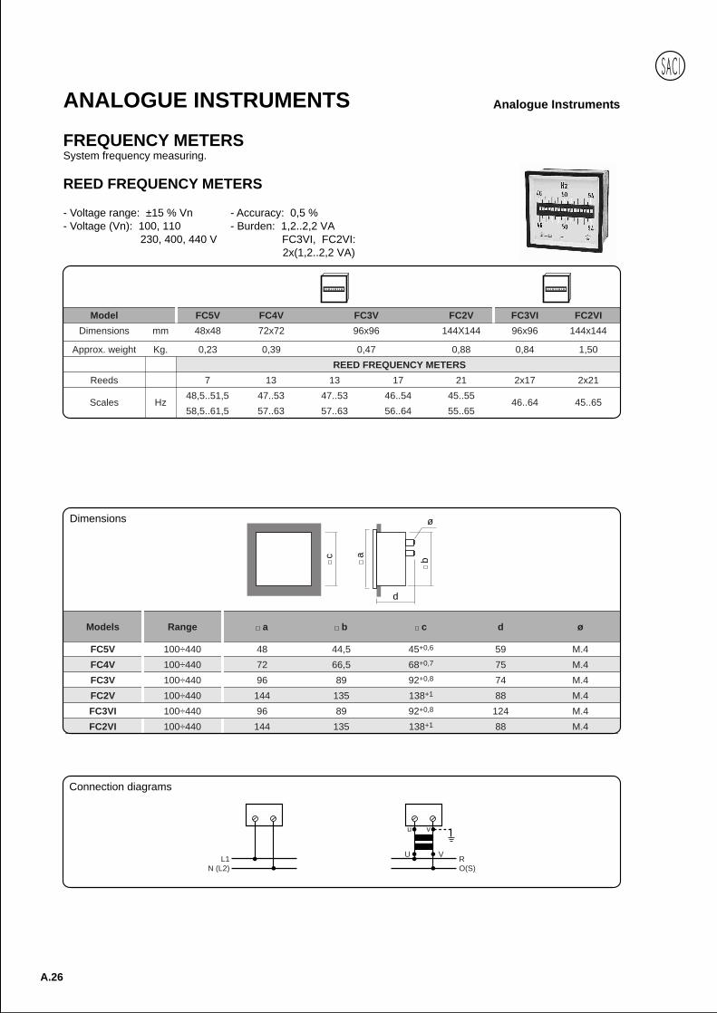
FREQUENCY METERSSystem frequency measuring.
REED FREQUENCY METERS
- Voltage range: ±15 % Vn - Accuracy: 0,5 %- Voltage (Vn): 100, 110 - Burden: 1,2..2,2 VA
230, 400, 440 V FC3VI, FC2VI:2x(1,2..2,2 VA)
Model FC5V FC4V FC3V FC2V FC3VI FC2VI
Dimensions mm 48x48 72x72 96x96 144X144 96x96 144x144
Approx. weight Kg. 0,23 0,39 0,47 0,88 0,84 1,50
REED FREQUENCY METERS
Reeds 7 13 13 17 21 2x17 2x21
Scales Hz48,5..51,5 47..53 47..53 46..54 45..55
46..64 45..6558,5..61,5 57..63 57..63 56..64 55..65
L1N (L2)
RO(S)
U V
vu
Models Range a b c d ø
FC5V 100÷440 48 44,5 45+0,6 59 M.4
FC4V 100÷440 72 66,5 68+0,7 75 M.4
FC3V 100÷440 96 89 92+0,8 74 M.4
FC2V 100÷440 144 135 138+1 88 M.4
FC3VI 100÷440 96 89 92+0,8 124 M.4
FC2VI 100÷440 144 135 138+1 88 M.4
c
d
b
ø
a
Connection diagrams
Dimensions

Anal
ogue
A.27
Analogue InstrumentsANALOGUE INSTRUMENTS
POINTER FREQUENCY METERS
- Voltage range: ±15 % Vn - Accuracy: 0,5 %- Voltage (Vn): 100, 110 - Burden: 10 mA
230, 400, 440 V
DIN RAIL DIN RAIL
Model FC5AR FC5A FC4A FC3A FC2A FC5ARI FC5AI FC4AI FC3AI FC2AI
Dimensions mm 45x52,5 48x48 72x72 96x96 144x144 45x52,5 48x48 72x72 96x96 144x144
Approx. weight Kg. 0,20 0,20 0,21 0,28 0,50 0,20 0,20 0,21 0,28 0,50
POINTER FREQUENCY METERS 90º
Scales Hz 45..55; 48..52; 55..65; 58..62 or 380..420 Hz 45..65 Hz
90º SCALE
240º SCALE
Model FC5C* FC4C FC3C FC2C FC5CI* FC4CI FC3CI FC2CI
Dimensions mm 48x48 72x72 96x96 144x144 48x48 72x72 96x96 144x144
Approx. weight Kg. 0,25 0,46 0,55 1,05 0,25 0,46 0,55 1,05
POINTER FREQUENCY METERS 240º
Scales Hz 45..55; 48..52; 55..65; 58..62 or 380..420 Hz 45..65 Hz* With additional module: MBF model
Models Range a b c d e ø
FC5AR 100÷230 52,5 45 75 60 38 M.6
FC5AIR 100÷230 52,5 45 75 60 38 M.6
e
a
c b
35,5
6 728,5
Ø 4,3Ø d
52,5
90 93 45 62
2548
58
DIN rail MBF moduleDimensions
Dimensions
Weight = 0,120Plug-in connectors
A.28
Analogue InstrumentsANALOGUE INSTRUMENTS
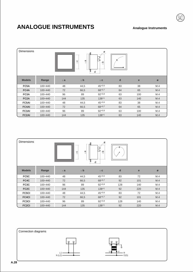
Models Range a b c d e ø
FC5A 100÷440 48 44,5 45+0,6 83 38 M.4
FC4A 100÷440 72 66,5 68+0,7 64 65 M.4
FC3A 100÷440 96 89 92+0,8 63 100 M.4
FC2A 100÷440 144 135 138+1 63 140 M.4
FC5AI 100÷440 48 44,5 45+0,6 83 38 M.4
FC4AI 100÷440 72 66,5 68+0,7 64 65 M.4
FC3AI 100÷440 96 89 92+0,8 63 100 M.4
FC2AI 100÷440 144 135 138+1 63 140 M.4
ec
d
b
ø
a
L1N (L2)
RO(S)
U V
vu
Connection diagrams
Dimensions
Models Range a b c d e ø
FC5C 100÷440 48 44,5 45+0,6 83 72 M.4
FC4C 100÷440 72 66,5 68+0,7 92 101 M.4
FC3C 100÷440 96 89 92+0,8 128 140 M.4
FC2C 100÷440 144 135 138+1 92 220 M.4
FC5CI 100÷440 48 44,5 45+0,6 83 72 M.4
FC4CI 100÷440 72 66,5 68+0,7 92 101 M.4
FC3CI 100÷440 96 89 92+0,8 128 140 M.4
FC2CI 100÷440 144 135 138+1 92 220 M.4
c a
d
b
ø
e
Dimensions

Anal
ogue
A.29
Analogue InstrumentsANALOGUE INSTRUMENTS
WATTMETERS (ELECTRONIC)System active power measuring.
Alternating current
- Frequency: 50 or 60 Hz - Accuracy: 1,5 %- Voltage range: ±15 % Vn - Burden: 3..12 mA- Voltage (Vn): 100, 110 (Voltage circuits)
230, 400, 440 V - Burden: 1..3,5 VA- Current range: 20-120% (Current circuits)
- Current input (In): 5A, 1A
Dimensions and connection diagrams, available on page A29-30.
90º SCALE
Dimensions mm 45x52,5 48x48 72x72 96x96 144x144
AC. SINGLE-PHASE - BALANCED THREE-PHASE
Approx. weight Kg. 0,55 0,55 0,55 0,84 0,84
AC. Single-phase WC5VRE* WC5VE* WC4VE* WC3VE WC2VE
Three-phase, 3 or 4 wire WC5VRIE* WC5VIE* WC4VIE* WC3VIE WC2VIE
UNBALANCED THREE-PHASE
Approx. weight Kg. 1,00 1,00 1,00 1,55 1,55
Three-phase, 3 wire WC5VRIIE* WC5VIIE* WC4VIIE* WC3VIIE WC2VIIE
Three-phase, 4 wire WC5VR3E* WC5V3E* WC4V3E* WC3V3E WC2V3E
DIN RAIL
INTERCHANGEABLE SCALE (90° scale only), for models: WC5V..., WC5VR..., WC4V... and WC3V...For 3 or 4 wire, balanced or unbalanced three-phase systems, the instruments and scales are:
Instruments 110 V, 5 A 230 V, 5 A 400 V, 5 A 440 V, 5 A
Calibration 1000 W 2000 W 3000 W 3000 W
Transformator Scales
10/5 A 0-2 kW 0-4 kW 0-6 kW 0-6 kW
15/5 A 0-3 kW 0-6 kW 0-9 kW 0-9 kW
20/5 A 0-4 kW 0-8 kW 0-12 kW 0-12 kW
25/5 A 0-5 kW 0-10 kW 0-15 kW 0-15 kW
30/5 A 0-6 kW 0-12 kW 0-18 kW 0-18 kW
Instruments 110 V, 5 A 230 V, 5 A 400 V, 5 A 440 V, 5 A
Calibration 1000 W 2000 W 3000 W 3000 W
Transformator Scales
40/5 A 0-8 kW 0-15 kW 0-24 kW 0-24 kW
50/5 A 0-10 kW 0-20 kW 0-30 kW 0-30 kW
60/5 A 0-12 kW 0-24 kW 0-36 kW 0-36 kW
75/5 A 0-15 kW 0-30 kW 0-45 kW 0-45 kW
Multiples Multiples Multiples Multiples Multiples
* With additional module: MBW... Models
240º SCALE
Dimensions mm 48x48 72x72 96x96 144x144
AC. SINGLE-PHASE - BALANCED THREE-PHASE
Approx. weight Kg. 0,55 0,55 0,84 0,84
AC. Single-phase WC5CE* WC4CE* WC3CE WC2CE
Three-phase, 3 or 4 wire WC5CIE* WC4CIE* WC3CIE WC2CIE
UNBALANCED THREE-PHASE
Approx. weight Kg. 1,00 1,00 1,55 1,55
Three-phase, 3 wire WC5CIIE* WC4CIIE* WC3CIIE WC2CIIE
Three-phase, 4 wire WC5C3E* WC4C3E* WC3C3E WC2C3E
A.30
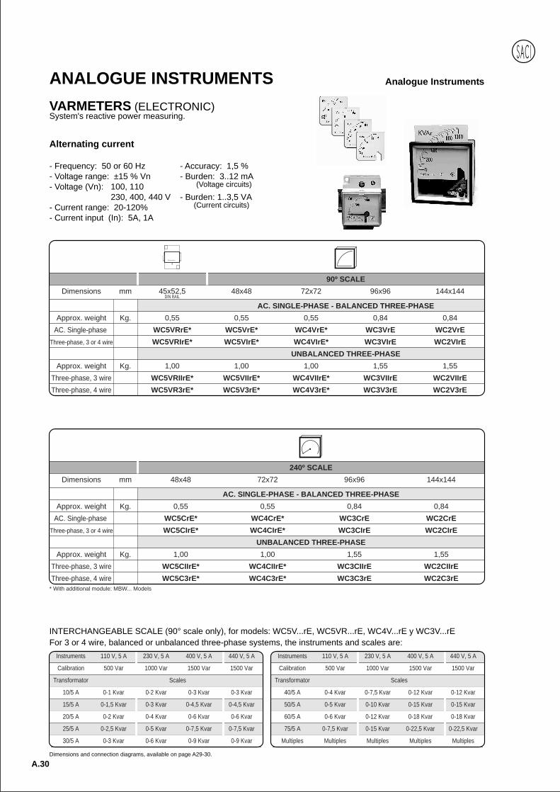
Analogue InstrumentsANALOGUE INSTRUMENTSVARMETERS (ELECTRONIC)System's reactive power measuring.
Alternating current
- Frequency: 50 or 60 Hz - Accuracy: 1,5 %- Voltage range: ±15 % Vn - Burden: 3..12 mA- Voltage (Vn): 100, 110 (Voltage circuits)
230, 400, 440 V - Burden: 1..3,5 VA- Current range: 20-120% (Current circuits)
- Current input (In): 5A, 1A
Dimensions and connection diagrams, available on page A29-30.
90º SCALE
Dimensions mm 45x52,5 48x48 72x72 96x96 144x144
AC. SINGLE-PHASE - BALANCED THREE-PHASE
Approx. weight Kg. 0,55 0,55 0,55 0,84 0,84
AC. Single-phase WC5VRrE* WC5VrE* WC4VrE* WC3VrE WC2VrE
Three-phase, 3 or 4 wire WC5VRIrE* WC5VIrE* WC4VIrE* WC3VIrE WC2VIrE
UNBALANCED THREE-PHASE
Approx. weight Kg. 1,00 1,00 1,00 1,55 1,55
Three-phase, 3 wire WC5VRIIrE* WC5VIIrE* WC4VIIrE* WC3VIIrE WC2VIIrE
Three-phase, 4 wire WC5VR3rE* WC5V3rE* WC4V3rE* WC3V3rE WC2V3rE
DIN RAIL
INTERCHANGEABLE SCALE (90° scale only), for models: WC5V...rE, WC5VR...rE, WC4V...rE y WC3V...rEFor 3 or 4 wire, balanced or unbalanced three-phase systems, the instruments and scales are:
Instruments 110 V, 5 A 230 V, 5 A 400 V, 5 A 440 V, 5 A
Calibration 500 Var 1000 Var 1500 Var 1500 Var
Transformator Scales
10/5 A 0-1 Kvar 0-2 Kvar 0-3 Kvar 0-3 Kvar
15/5 A 0-1,5 Kvar 0-3 Kvar 0-4,5 Kvar 0-4,5 Kvar
20/5 A 0-2 Kvar 0-4 Kvar 0-6 Kvar 0-6 Kvar
25/5 A 0-2,5 Kvar 0-5 Kvar 0-7,5 Kvar 0-7,5 Kvar
30/5 A 0-3 Kvar 0-6 Kvar 0-9 Kvar 0-9 Kvar
Instruments 110 V, 5 A 230 V, 5 A 400 V, 5 A 440 V, 5 A
Calibration 500 Var 1000 Var 1500 Var 1500 Var
Transformator Scales
40/5 A 0-4 Kvar 0-7,5 Kvar 0-12 Kvar 0-12 Kvar
50/5 A 0-5 Kvar 0-10 Kvar 0-15 Kvar 0-15 Kvar
60/5 A 0-6 Kvar 0-12 Kvar 0-18 Kvar 0-18 Kvar
75/5 A 0-7,5 Kvar 0-15 Kvar 0-22,5 Kvar 0-22,5 Kvar
Multiples Multiples Multiples Multiples Multiples
* With additional module: MBW... Models
240º SCALE
Dimensions mm 48x48 72x72 96x96 144x144
AC. SINGLE-PHASE - BALANCED THREE-PHASE
Approx. weight Kg. 0,55 0,55 0,84 0,84
AC. Single-phase WC5CrE* WC4CrE* WC3CrE WC2CrE
Three-phase, 3 or 4 wire WC5CIrE* WC4CIrE* WC3CIrE WC2CIrE
UNBALANCED THREE-PHASE
Approx. weight Kg. 1,00 1,00 1,55 1,55
Three-phase, 3 wire WC5CIIrE* WC4CIIrE* WC3CIIrE WC2CIIrE
Three-phase, 4 wire WC5C3rE* WC4C3rE* WC3C3rE WC2C3rE
Anal
ogue
A.31
Analogue InstrumentsANALOGUE INSTRUMENTS
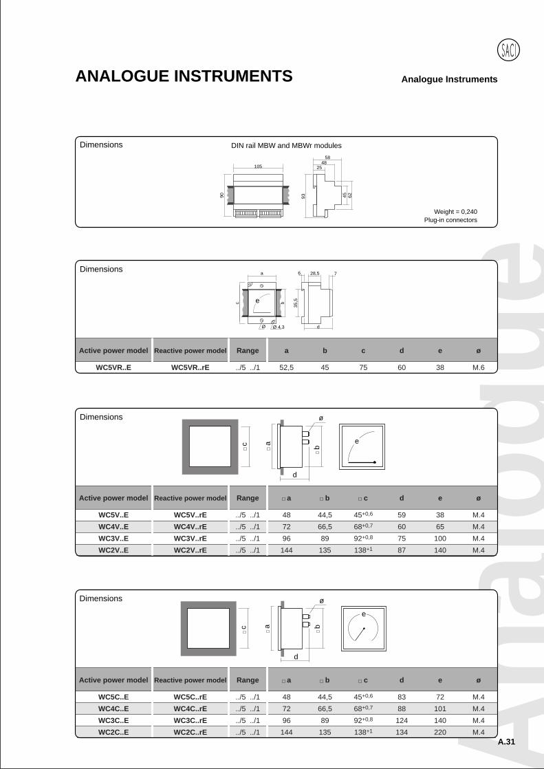
Active power model Reactive power model Range a b c d e ø
WC5V..E WC5V..rE ../5 ../1 48 44,5 45+0,6 59 38 M.4
WC4V..E WC4V..rE ../5 ../1 72 66,5 68+0,7 60 65 M.4
WC3V..E WC3V..rE ../5 ../1 96 89 92+0,8 75 100 M.4
WC2V..E WC2V..rE ../5 ../1 144 135 138+1 87 140 M.4
ec
d
b
ø
a
DIN rail MBW and MBWr modules
105
90 93 45 62
2548
58
e
a
c b
35,5
6 728,5
Ø 4,3Ø d
Active power model Reactive power model Range a b c d e ø
WC5VR..E WC5VR..rE ../5 ../1 52,5 45 75 60 38 M.6
c a
d
b
ø
e
Active power model Reactive power model Range a b c d e ø
WC5C..E WC5C..rE ../5 ../1 48 44,5 45+0,6 83 72 M.4
WC4C..E WC4C..rE ../5 ../1 72 66,5 68+0,7 88 101 M.4
WC3C..E WC3C..rE ../5 ../1 96 89 92+0,8 124 140 M.4
WC2C..E WC2C..rE ../5 ../1 144 135 138+1 134 220 M.4
Dimensions
Dimensions
Dimensions
Dimensions
Weight = 0,240Plug-in connectors
A.32
Analogue InstrumentsANALOGUE INSTRUMENTS
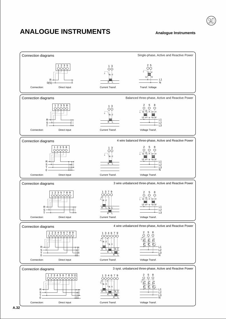
3 syst. unbalanced three-phase, Active and Reactive Power
Connection: Current Transf. Voltage Transf.Direct input
4 wire unbalanced three-phase, Active and Reactive Power
Connection: Current Transf. Voltage Transf.Direct input
3 wire unbalanced three-phase, Active and Reactive Power
Connection: Current Transf. Voltage Transf.Direct input
4 wire balanced three-phase, Active and Reactive Power
Connection: Current Transf. Voltage Transf.Direct input
1 3
K L
k l
RST0
1 2 3 5 8 2 5 8
L1L2L3N
u v u v
U V U V
Balanced three-phase, Active and Reactive Power
Connection: Current Transf. Voltage Transf.Direct input
2 5 8
L1L2L3
u v u v
U V U V
1 3
K L
k l
RST
1 2 3 5 8
Single-phase, Active and Reactive Power
Connection: Current Transf.
1 3
K L
k l
2 5
U V
u v
L1N
Transf. Voltage
R0(S)
1 2 3 5
Direct input
RST
1 2 3 5 7 8 9 2 5 8
L1L2L3
u v u v
U V U V
1 3 7 9
K L
K L
k l
k l
RST0
1 2 3 4 5 6 7 8 9 1 3 4 6 7 9
K LK L
K L
k lk l
k l
2 5 8
u u ux x xx x xu u u
L1L2L3N
RST0
1 2 3 4 5 6 7 8 9 11 1 3 4 6 7 9
K LK L
K L
k lk l
k l
2 5 8
u u ux x xx x xu u u
L1L2L3N
Connection diagrams
Connection diagrams
Connection diagrams
Connection diagrams
Connection diagrams
Connection diagrams
Anal
ogue
A.33
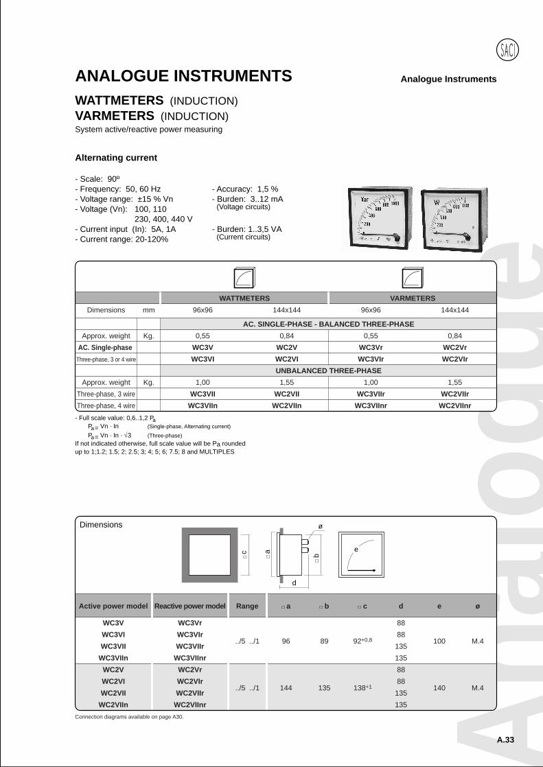
Analogue InstrumentsANALOGUE INSTRUMENTSWATTMETERS (INDUCTION)VARMETERS (INDUCTION)System active/reactive power measuring
WATTMETERS VARMETERS
Dimensions mm 96x96 144x144 96x96 144x144
AC. SINGLE-PHASE - BALANCED THREE-PHASE
Approx. weight Kg. 0,55 0,84 0,55 0,84
AC. Single-phase WC3V WC2V WC3Vr WC2Vr
Three-phase, 3 or 4 wire WC3VI WC2VI WC3VIr WC2VIr
UNBALANCED THREE-PHASE
Approx. weight Kg. 1,00 1,55 1,00 1,55
Three-phase, 3 wire WC3VII WC2VII WC3VIIr WC2VIIr
Three-phase, 4 wire WC3VIIn WC2VIIn WC3VIInr WC2VIInr
Alternating current
- Scale: 90º- Frequency: 50, 60 Hz - Accuracy: 1,5 %- Voltage range: ±15 % Vn - Burden: 3..12 mA- Voltage (Vn): 100, 110 (Voltage circuits)
230, 400, 440 V- Current input (In): 5A, 1A - Burden: 1..3,5 VA- Current range: 20-120% (Current circuits)
- Full scale value: 0,6..1,2 PaPa = Vn · In (Single-phase, Alternating current)
Pa = Vn · In · 3 (Three-phase)If not indicated otherwise, full scale value will be Pa roundedup to 1;1.2; 1.5; 2; 2.5; 3; 4; 5; 6; 7.5; 8 and MULTIPLES
Connection diagrams available on page A30.
Active power model Reactive power model Range a b c d e ø
WC3V WC3Vr 88
WC3VI WC3VIr 88
WC3VII WC3VIIr../5 ../1 96 89 92+0,8
135100 M.4
WC3VIIn WC3VIInr 135
WC2V WC2Vr 88
WC2VI WC2VIr 88
WC2VII WC2VIIr../5 ../1 144 135 138+1
135140 M.4
WC2VIIn WC2VIInr 135
ec
d
b
ø
a
Dimensions
A.34
Analogue InstrumentsANALOGUE INSTRUMENTS
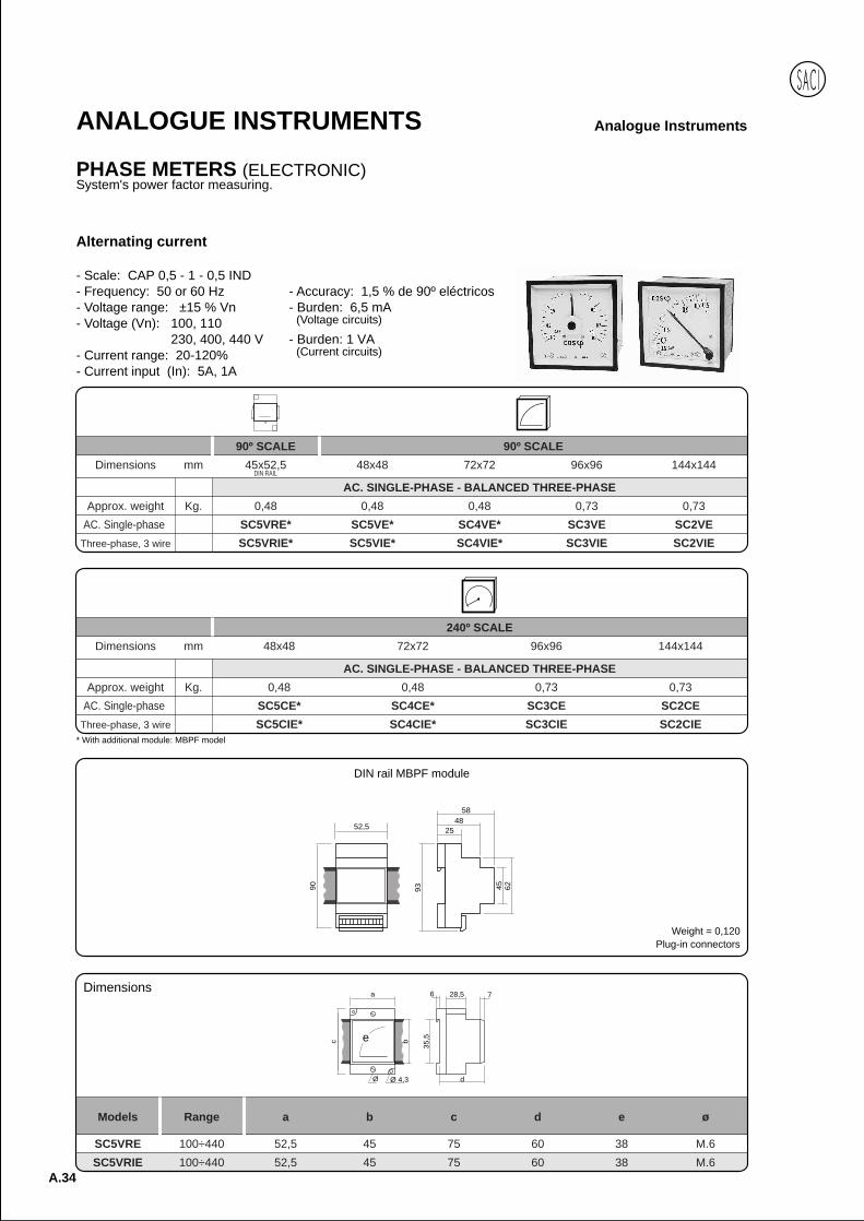
PHASE METERS (ELECTRONIC)System's power factor measuring.
Alternating current
- Scale: CAP 0,5 - 1 - 0,5 IND- Frequency: 50 or 60 Hz - Accuracy: 1,5 % de 90º eléctricos- Voltage range: ±15 % Vn - Burden: 6,5 mA- Voltage (Vn): 100, 110 (Voltage circuits)
230, 400, 440 V - Burden: 1 VA- Current range: 20-120% (Current circuits)
- Current input (In): 5A, 1A
90º SCALE 90º SCALE
Dimensions mm 45x52,5 48x48 72x72 96x96 144x144
AC. SINGLE-PHASE - BALANCED THREE-PHASE
Approx. weight Kg. 0,48 0,48 0,48 0,73 0,73
AC. Single-phase SC5VRE* SC5VE* SC4VE* SC3VE SC2VE
Three-phase, 3 wire SC5VRIE* SC5VIE* SC4VIE* SC3VIE SC2VIE
DIN RAIL
Models Range a b c d e ø
SC5VRE 100÷440 52,5 45 75 60 38 M.6
SC5VRIE 100÷440 52,5 45 75 60 38 M.6
e
a
c b
35,5
6 728,5
Ø 4,3Ø d
Dimensions
* With additional module: MBPF model
240º SCALE
Dimensions mm 48x48 72x72 96x96 144x144
AC. SINGLE-PHASE - BALANCED THREE-PHASE
Approx. weight Kg. 0,48 0,48 0,73 0,73
AC. Single-phase SC5CE* SC4CE* SC3CE SC2CE
Three-phase, 3 wire SC5CIE* SC4CIE* SC3CIE SC2CIE
52,5
90 93 45 62
2548
58
DIN rail MBPF module
Weight = 0,120Plug-in connectors
Anal
ogue
A.35
Analogue InstrumentsANALOGUE INSTRUMENTS
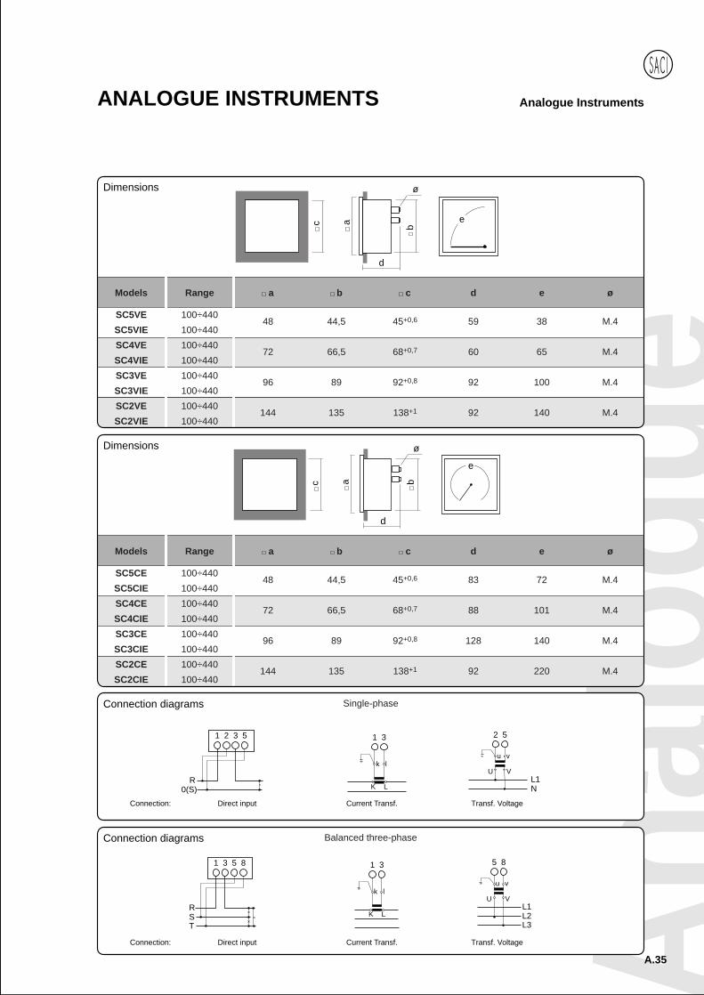
Models Range a b c d e ø
SC5VE 100÷44048 44,5 45+0,6 59 38 M.4
SC5VIE 100÷440
SC4VE 100÷44072 66,5 68+0,7 60 65 M.4
SC4VIE 100÷440
SC3VE 100÷44096 89 92+0,8 92 100 M.4
SC3VIE 100÷440
SC2VE 100÷440144 135 138+1 92 140 M.4
SC2VIE 100÷440
ec
d
b
ø
a
c a
d
b
ø
e
Models Range a b c d e ø
SC5CE 100÷44048 44,5 45+0,6 83 72 M.4
SC5CIE 100÷440
SC4CE 100÷44072 66,5 68+0,7 88 101 M.4
SC4CIE 100÷440
SC3CE 100÷44096 89 92+0,8 128 140 M.4
SC3CIE 100÷440
SC2CE 100÷440144 135 138+1 92 220 M.4
SC2CIE 100÷440
Single-phase
Connection: Current Transf.
1 3
K L
k l
2 5
U V
u v
L1N
Transf. Voltage
R0(S)
1 2 3 5
Direct input
1 3
K L
k l
RS
1 3 5 8
T
5 8
U V
u v
L1L2L3
Balanced three-phase
Connection: Current Transf. Transf. VoltageDirect input
Connection diagrams
Dimensions
Dimensions
Connection diagrams
A.36
Analogue InstrumentsANALOGUE INSTRUMENTS
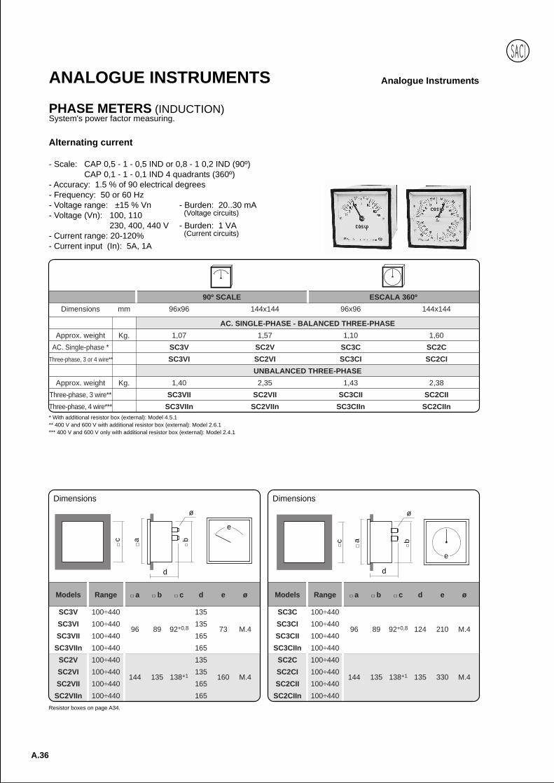
PHASE METERS (INDUCTION)System's power factor measuring.
90º SCALE ESCALA 360º
Dimensions mm 96x96 144x144 96x96 144x144
AC. SINGLE-PHASE - BALANCED THREE-PHASE
Approx. weight Kg. 1,07 1,57 1,10 1,60
AC. Single-phase * SC3V SC2V SC3C SC2C
Three-phase, 3 or 4 wire** SC3VI SC2VI SC3CI SC2CI
UNBALANCED THREE-PHASE
Approx. weight Kg. 1,40 2,35 1,43 2,38
Three-phase, 3 wire** SC3VII SC2VII SC3CII SC2CII
Three-phase, 4 wire*** SC3VIIn SC2VIIn SC3CIIn SC2CIIn
Alternating current
- Scale: CAP 0,5 - 1 - 0,5 IND or 0,8 - 1 0,2 IND (90º)CAP 0,1 - 1 - 0,1 IND 4 quadrants (360º)
- Accuracy: 1.5 % of 90 electrical degrees- Frequency: 50 or 60 Hz- Voltage range: ±15 % Vn - Burden: 20..30 mA- Voltage (Vn): 100, 110 (Voltage circuits)
230, 400, 440 V - Burden: 1 VA- Current range: 20-120% (Current circuits)
- Current input (In): 5A, 1A
* With additional resistor box (external): Model 4.5.1** 400 V and 600 V with additional resistor box (external): Model 2.6.1*** 400 V and 600 V only with additional resistor box (external): Model 2.4.1
Resistor boxes on page A34.
Models Range a b c d e ø
SC3C 100÷440
SC3CI 100÷44096 89 92+0,8 124 210 M.4
SC3CII 100÷440
SC3CIIn 100÷440
SC2C 100÷440
SC2CI 100÷440144 135 138+1 135 330 M.4
SC2CII 100÷440
SC2CIIn 100÷440
e
c a
d
b
ø
Dimensions
e
c a
d
b
ø
Models Range a b c d e ø
SC3V 100÷440 135
SC3VI 100÷44096 89 92+0,8 135
73 M.4SC3VII 100÷440 165
SC3VIIn 100÷440 165
SC2V 100÷440 135
SC2VI 100÷440144 135 138+1 135
160 M.4SC2VII 100÷440 165
SC2VIIn 100÷440 165
Dimensions
Anal
ogue
A.37
Analogue InstrumentsANALOGUE INSTRUMENTS
2 5
U V
u v
L1N
R0(S)
1 B 3 E HB E H
52
1 3
K L
k l
RST
1 2 3 5 8 2 5 8
L1L2L3
u v u v
U V U V
1 3
K L
k l
2 5 8
L1L2L3
u v u v
U V U VRST
1 B 3 E HB E H2 5 8
1 3
K L
k l
RST
1 2 3 7 5 9 8 2 5 8
L1L2L3
u v u v
U V U V
1 3 7 9
K L
K L
k lk l
2 5 8
L1L2L3
u v u v
U V U VRST
1 B 3 7 E 9 HB E H
2 5 8
1 3 7 9
K L
K L
k lk l
0
RST
1 2 3 4 6 7 8 9 2 8
U V
u v
L1L2L3N
1 3 4 6 7 9
K LK L
K L
k lk l
k l
1 3 4 6 7 9
K LK L
K L
k lk l
k lRST
1 B 3 4 6 7 H 9
0
B H2 8
2 8
U V
u v
L1L2L3N
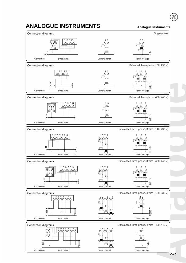
Unbalanced three-phase, 4 wire (400, 440 V)
Connection: Current Transf. Transf. VoltageDirect input
Unbalanced three-phase, 4 wire (100, 230 V)
Connection: Current Transf. Transf. VoltageDirect input
Unbalanced three-phase, 3 wire (400, 440 V)
Connection: Current Transf. Transf. VoltageDirect input
Unbalanced three-phase, 3 wire (110, 230 V)
Connection: Current Transf. Transf. VoltageDirect input
Balanced three-phase (400, 440 V)
Connection: Current Transf. Transf. VoltageDirect input
Balanced three-phase (100, 230 V)
Connection: Current Transf. Transf. VoltageDirect input
Single-phase
Connection: Current Transf. Transf. VoltageDirect input
Connection diagrams
Connection diagrams
Connection diagrams
Connection diagrams
Connection diagrams
Connection diagrams
Connection diagrams

A.38
Analogue InstrumentsANALOGUE INSTRUMENTS
RESISTOR BOXESConnection to measuring elements.
- Accuracy: 0,5 %
Model 1.2.1 1.3.1 1.4.1 1.4.2 1.5.1 1.6.1 1.6.2
Terminals 2 3 4 4 5 6 6
Approx. weight Kg. 0,23 0,23 0,24 0,31 0,50 0,25 0,40
Model 2.2.1 2.3.1 2.4.1 2.4.2 2.5.2 2.6.1 2.6.2 2.6.3 2.7.1 2.8.1 2.8.2
Terminals 2 3 4 4 5 6 6 6 7 8 8
Approx. weight Kg. 0,31 0,31 0,31 0,31 0,32 0,32 0,55 0,74 0,40 0,60 0,77
Model 3.3.1 3.3.2 4.2.1 4.3.1 4.4.1 4.5.1 4.6.1 4.8.1
Terminals 3 3 2 3 4 5 6 8
Approx. weight Kg. 0,27 0,70 0,90 0,90 0,95 1,00 1,00 1,00
BA
152
50
120
134,5
6,5
Model 1..1 2..1
A 64 99
B 86 121
A
B
E
D
6,5
FC
Model 3.3.1 3.3.2
A 155 270
B 50 100
C 101 148
D 135 235
E 120 220
F 69 102
6,5
135
74
170
155
17123100
Model
4.5.1
4.6.1
4.8.1
Dimensions Dimensions Dimensions
Anal
ogue
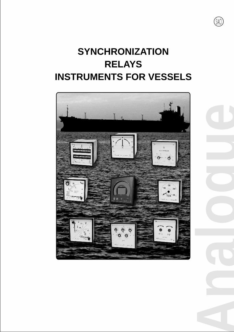
SYNCHRONIZATIONRELAYS
INSTRUMENTS FOR VESSELS
A.40
ANALOGUE INSTRUMENTS
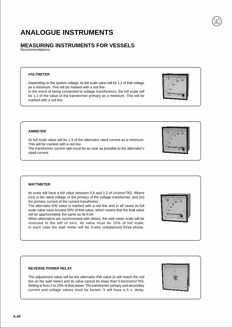
MEASURING INSTRUMENTS FOR VESSELSRecommendations.
REVERSE POWER RELAY
The adjustment value will be the alternator KW value (it will match the redline on the watt meter) and its value cannot be lower than 0.6xUnxInx•'763.Setting is from 2 to 15% of that power. The transformer primary and secondarycurrent and voltage values must be known. It will have a 5 s. delay.
AMMETER
Its full scale value will be 1.3 of the alternator rated current as a minimum.This will be marked with a red line.The transformer current ratio must be as near as possible to the alternator'srated current.
VOLTMETER
Depending on the system voltage, its full scale value will be 1.2 of that voltageas a minimum. This will be marked with a red line.In the event of being connected to voltage transformers, the full scale willbe 1.2 of the value of the transformer primary as a minimum. This will bemarked with a red line.
WATTMETER
Its scale will have a full value between 0.6 and 1.2 of UnxInx•'763. Where(Un) is the rated voltage or the primary of the voltage transformer, and (In)the primary current of the current transformer.The alternator KW value is marked with a red line and in all cases its fullscale value must exceed 20% of that value, which means that the final valuewill be approximately the same as its KVA.When alternators are synchronised with others, the watt meter scale will bereversed to the left of zero. Its value must be 15% of full scale.In each case the watt meter will be 3-wire unbalanced three-phase.

Anal
ogue
A.41
Analogue InstrumentsANALOGUE INSTRUMENTS
MEASURING INSTRUMENTS FOR VESSELSRecommendations.
MAXIMUM CURRENT RELAY
It may be connected to any x/5 A current transformer, but the availableauxiliary voltage must be known.
SYNCHRONIZING RELAY
As a synchronizing auxiliary element, the selection and polarity of the voltagepower supply must be correct.The width of the chosen phase and time parameters will depend on the levelof response sensitivity to the alternators' speed and voltage settings and thevalue allowed by the group.
BAR INSULATION INDICATORS
The instrument must be supplied directly by the three phases via a leakageanalysis switch and never to the voltage transformer secondaries. The systempower supply voltage and the available auxiliary power supply of the alarmcircuit will be indicated.This instrument must never be connected to three-phase systems with neutralconnected to earth.
CURRENT TRANSFORMERS
Their power depends on the consumption of the instruments to be connected.At least 10VA in class 0.5 is recommended to avoid accuracy and angleerrors. Polarity must be correct.
VOLTAGE TRANSFORMERS
The TE-15R model is specially designed for this application due to its powerand accuracy (25VA, class 1). This allows all instruments that the controlequipment usually has to be connected to the secondary without theintroduction of ratio or phase errors.No special recommendations are required for other instruments used invessel control equipment.
A.42
Analogue InstrumentsANALOGUE INSTRUMENTSFOR SYNCHRONIZING INSTRUMENTS
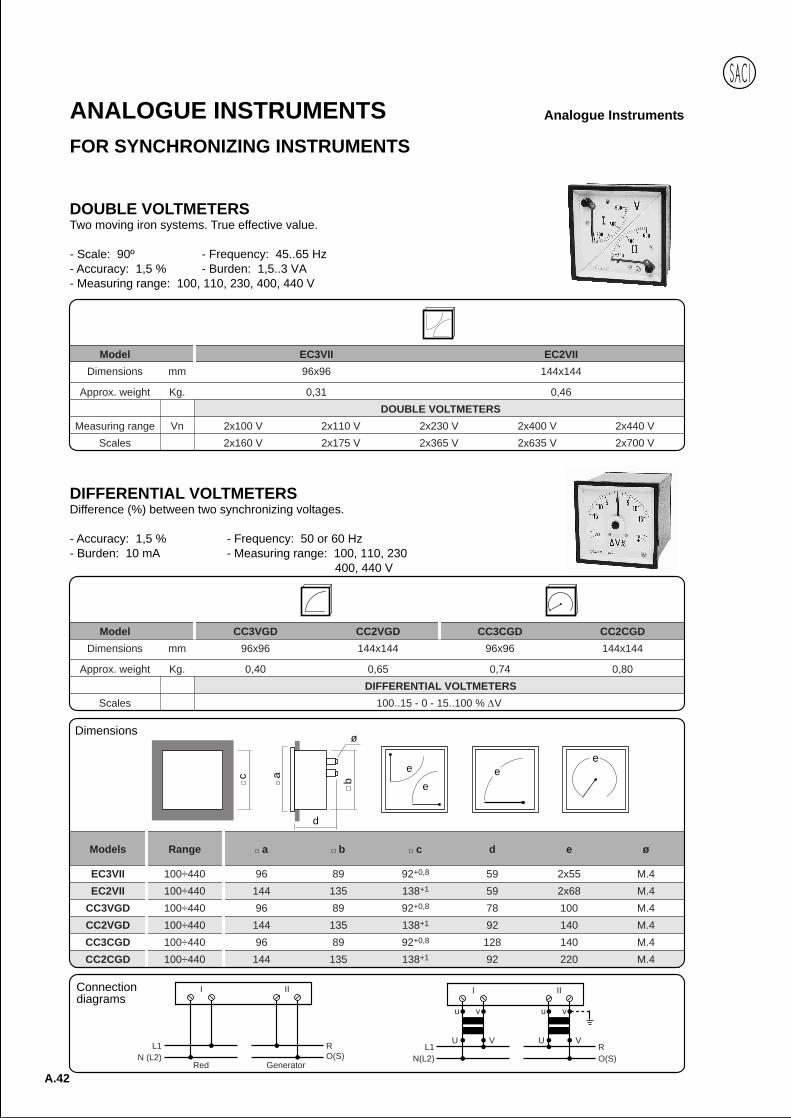
DOUBLE VOLTMETERSTwo moving iron systems. True effective value.
- Scale: 90º - Frequency: 45..65 Hz- Accuracy: 1,5 % - Burden: 1,5..3 VA- Measuring range: 100, 110, 230, 400, 440 V
Model EC3VII EC2VII
Dimensions mm 96x96 144x144
Approx. weight Kg. 0,31 0,46
DOUBLE VOLTMETERS
Measuring range Vn 2x100 V 2x110 V 2x230 V 2x400 V 2x440 V
Scales 2x160 V 2x175 V 2x365 V 2x635 V 2x700 V
DIFFERENTIAL VOLTMETERSDifference (%) between two synchronizing voltages.
- Accuracy: 1,5 % - Frequency: 50 or 60 Hz- Burden: 10 mA - Measuring range: 100, 110, 230
400, 440 V
Model CC3VGD CC2VGD CC3CGD CC2CGD
Dimensions mm 96x96 144x144 96x96 144x144
Approx. weight Kg. 0,40 0,65 0,74 0,80
DIFFERENTIAL VOLTMETERS
Scales 100..15 - 0 - 15..100 % V
Models Range a b c d e ø
EC3VII 100÷440 96 89 92+0,8 59 2x55 M.4
EC2VII 100÷440 144 135 138+1 59 2x68 M.4
CC3VGD 100÷440 96 89 92+0,8 78 100 M.4
CC2VGD 100÷440 144 135 138+1 92 140 M.4
CC3CGD 100÷440 96 89 92+0,8 128 140 M.4
CC2CGD 100÷440 144 135 138+1 92 220 M.4
ec
d
b
ø
a e
e
e
RO(S)
U V
vu
U V
vu
L1N(L2)
I II
L1N (L2)
RO(S)
I II
Red Generator
Connectiondiagrams
Dimensions
Anal
ogue
A.43
Analogue InstrumentsANALOGUE INSTRUMENTS
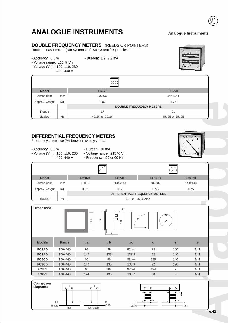
DOUBLE FREQUENCY METERS (REEDS OR POINTERS)Double measurement (two systems) of two system frequencies.
- Accuracy: 0,5 % - Burden: 1,2..2,2 mA- Voltage range: ±15 % Vn- Voltage (Vn): 100, 110, 230
400, 440 V
Model FC3VII FC2VII
Dimensions mm 96x96 144x144
Approx. weight Kg. 0,87 1,25
DOUBLE FREQUENCY METERS
Reeds 17 21
Scales Hz 46..54 or 56..64 45..55 or 55..65
DIFFERENTIAL FREQUENCY METERSFrequency difference (%) between two systems.
- Accuracy: 0,2 % - Burden: 10 mA- Voltage (Vn): 100, 110, 230 - Voltage range: ±15 % Vn
400, 440 V - Frequency: 50 or 60 Hz
Model FC3AD FC2AD FC3CD FC2CD
Dimensions mm 96x96 144x144 96x96 144x144
Approx. weight Kg. 0,32 0,50 0,55 0,75
DIFFERENTIAL FREQUENCY METERS
Scales % 10 - 0 - 10 % Hz
RO(S)
U V
vu
U V
vu
L1N(L2)
I II
L1N (L2)
RO(S)
I II
Red Generator
Connectiondiagrams
Models Range a b c d e ø
FC3AD 100÷440 96 89 92+0,8 78 100 M.4
FC2AD 100÷440 144 135 138+1 92 140 M.4
FC3CD 100÷440 96 89 92+0,8 128 140 M.4
FC2CD 100÷440 144 135 138+1 92 220 M.4
FC3VII 100÷440 96 89 92+0,8 124 - M.4
FC2VII 100÷440 144 135 138+1 88 - M.4
ee
c
d
b
ø
a
Dimensions
A.44
Analogue InstrumentsANALOGUE INSTRUMENTS
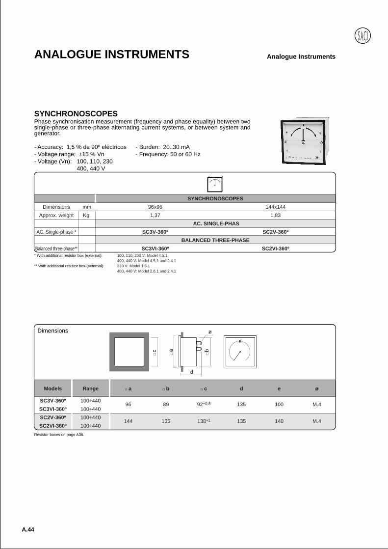
SYNCHRONOSCOPES
Dimensions mm 96x96 144x144
Approx. weight Kg. 1,37 1,83
AC. SINGLE-PHAS
AC. Single-phase * SC3V-360º SC2V-360º
BALANCED THREE-PHASE
Balanced three-phase** SC3VI-360º SC2VI-360º
SYNCHRONOSCOPESPhase synchronisation measurement (frequency and phase equality) between twosingle-phase or three-phase alternating current systems, or between system andgenerator.
- Accuracy: 1,5 % de 90º eléctricos - Burden: 20..30 mA- Voltage range: ±15 % Vn - Frequency: 50 or 60 Hz- Voltage (Vn): 100, 110, 230
400, 440 V
* With additional resistor box (external): 100, 110, 230 V: Model 4.5.1400, 440 V: Model 4.5.1 and 2.4.1
** With additional resistor box (external): 230 V: Model 1.6.1400, 440 V: Model 2.6.1 and 2.4.1
Resistor boxes on page A36.
c a
d
b
ø
e
Models Range a b c d e ø
SC3V-360º 100÷44096 89 92+0,8 135 100 M.4
SC3VI-360º 100÷440
SC2V-360º 100÷440144 135 138+1 135 140 M.4
SC2VI-360º 100÷440
Dimensions

Anal
ogue
A.45
Analogue InstrumentsANALOGUE INSTRUMENTS
Three-phase (400, 440 V)
Connection: Transf. Voltage Transf. VoltageDirect input
L1L2L3
26 28
U V
u v
RST
2 5 8
u v u v
U V U V
B E H X Z
X Z2826
B E H2 5 8
Red Generator
Single-phase (100, 110, 230 V)
Connection: Transf. Voltage Transf. VoltageDirect input
26 27
U V
u v
L1N
R0(S)
2 5
U V
u v
B E H 26
Red
27
B E H52
Generator
Single-phase (400, 440 V)
Connection: Transf. Voltage Transf. VoltageDirect input
26 27
U V
u v
L1N
R0(S)
2 5
U V
u v
B E H X YB E H
52X Y
2726
Red Generator
Three-phase (100, 110 V)
Connection: Transf. Voltage Transf. VoltageDirect input
26 28
U V
u v
L1L2L3
RST
2 5 8
u v u v
U V U V
2 5 8 2628
Red Generator
Three-phase (230 V)
Connection: Transf. Voltage Transf. VoltageDirect input
L1L2L3
26 28
U V
u v
RST
2 5 8
u v u v
U V U V
B E H 2628
B E H2 5 8
Red Generator
Connection diagramsConnection diagrams
Connection diagrams
Connection diagrams
Connection diagrams
Connection diagrams
A.46
Analogue InstrumentsANALOGUE INSTRUMENTS
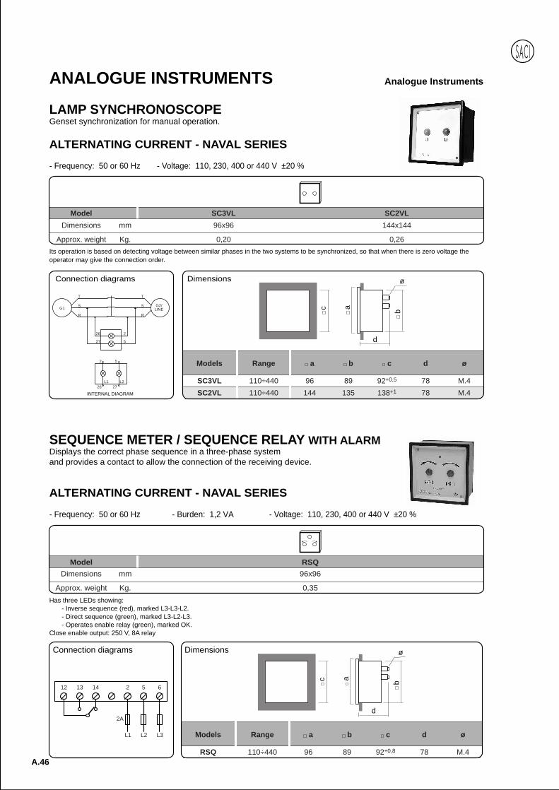
LAMP SYNCHRONOSCOPEGenset synchronization for manual operation.
Has three LEDs showing:- Inverse sequence (red), marked L3-L3-L2.- Direct sequence (green), marked L3-L2-L3.- Operates enable relay (green), marked OK.
Close enable output: 250 V, 8A relay
ALTERNATING CURRENT - NAVAL SERIES
- Frequency: 50 or 60 Hz - Burden: 1,2 VA - Voltage: 110, 230, 400 or 440 V ±20 %
Model RSQDimensions mm 96x96
Approx. weight Kg. 0,35
Its operation is based on detecting voltage between similar phases in the two systems to be synchronized, so that when there is zero voltage theoperator may give the connection order.
ALTERNATING CURRENT - NAVAL SERIES
- Frequency: 50 or 60 Hz - Voltage: 110, 230, 400 or 440 V ±20 %
Model SC3VL SC2VL
Dimensions mm 96x96 144x144
Approx. weight Kg. 0,20 0,26
Connection diagrams
Models Range a b c d ø
SC3VL 110÷440 96 89 92+0,5 78 M.4
SC2VL 110÷440 144 135 138+1 78 M.4
c
d
b
ø
aG1G2/
LINER
S
T
R
S
T
27
26
5
2
2726
52
L1 L2
INTERNAL DIAGRAM
Dimensions
SEQUENCE METER / SEQUENCE RELAY WITH ALARMDisplays the correct phase sequence in a three-phase systemand provides a contact to allow the connection of the receiving device.
2A
12 13 14 2 5 6
L1 L2 L3
Connection diagrams
Models Range a b c d ø
RSQ 110÷440 96 89 92+0,8 78 M.4
c
d
b
ø
a
Dimensions
Anal
ogue
A.47
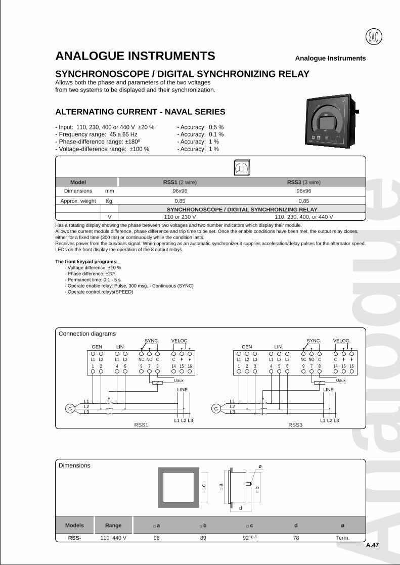
Analogue InstrumentsANALOGUE INSTRUMENTSSYNCHRONOSCOPE / DIGITAL SYNCHRONIZING RELAYAllows both the phase and parameters of the two voltagesfrom two systems to be displayed and their synchronization.
Model RSS1 (2 wire) RSS3 (3 wire)
Dimensions mm 96x96 96x96
Approx. weight Kg. 0,85 0,85
SYNCHRONOSCOPE / DIGITAL SYNCHRONIZING RELAYV 110 or 230 V 110, 230, 400, or 440 V
Has a rotating display showing the phase between two voltages and two number indicators which display their module.Allows the current module difference, phase difference and trip time to be set. Once the enable conditions have been met, the output relay closes,either for a fixed time (300 ms) or continuously while the condition lasts.Receives power from the bus/bars signal. When operating as an automatic synchronizer it supplies acceleration/delay pulses for the alternator speed.LEDs on the front display the operation of the 8 output relays.
The front keypad programs:- Voltage difference: ±10 %- Phase difference: ±20º- Permanent time: 0,1 - 5 s.- Operate enable relay: Pulse, 300 msg. - Continuous (SYNC)- Operate control relays(SPEED)
ALTERNATING CURRENT - NAVAL SERIES
- Input: 110, 230, 400 or 440 V ±20 % - Accuracy: 0,5 %- Frequency range: 45 a 65 Hz - Accuracy: 0,1 %- Phase-difference range: ±180º - Accuracy: 1 %- Voltage-difference range: ±100 % - Accuracy: 1 %
c
d
b
ø
a
Models Range a b c d ø
RSS- 110÷440 V 96 89 92+0,8 78 Term.
Connection diagrams
LINE
L1 L2 L2 NC NO C CL1
G
L1 L2 L3
1 2 5 9 7 8 144 15 16
L1L2L3
GEN LIN.SYNC. VELOC.
Uaux
RSS1
LINE
L2 L2
G
L1 L2 L3
1 2 54
L1L2L3
GEN LIN.
NC NO C9 7 8
SYNC.
Uaux
RSS3
C14 15 16
VELOC.
L1 L3 L1 L33 6
Dimensions

A.48
Analogue InstrumentsANALOGUE INSTRUMENTS
SYNCHRONIZING EQUIPMENTEquipment with three instruments, double or differential voltmeter, double or differentialfrequency meters and synchronoscope, for connecting two generators in parallel, orconnecting a generator with system.
Position: Vertical (as column with 180º turn)Horizontal (with two supports)
Technical specifications: see instrument data.
Model VOLTMETERS FREQUENCY METERS SYNCHRONOSCOPES
ES3V EC3VII or CC3VGD FC3VII or FC3AD SC3V-360º
ES3VI EC3VII or CC3VGD FC3VII or FC3AD SC3VI-360º
ES2V EC2VII or CC2VGD FC2VII or FC2AD or FC2AD SC2V-360º
ES2VI EC2VII or CC2VGD FC3VII or FC3AD or FC2AD SC2VI-360º
ES3C CC3CGD FC3CD SC3V-360º
ES3CI CC3CGD FC3CD SC3VI-360º
ES2C CC2CGD FC2CD SC2V-360º
ES2CI CC2CGD FC2CD SC2VI-360º
90º SCALE 240º SCALE
Dimensions mm 410x223x120 576x258x170 410x223x120 576x258x170
Dimensions mm 96x96 144x144 96x96 144x144
Approx. weight Kg. 5,70 9,00 5,80 8,70
SINGLE-PHASE
Single-phase ES3V ES2V ES3C ES2C
BALANCED THREE-PHASE
Balanced three-phase ES3VI ES2VI ES3CI ES2CI
EQUIPMENT
INSTRUMENTS
Single-phase
RO(S)
26 272 5
2 5
U V
u v
L1N
2627
U V
u v
System Generator Connection with voltage transf.
2628
U V
u v
2 5 8
L1L2L3
u v u v
U V U VRST
26 282 5 8
System Generator Connection with voltage transf.
Three-phase
Models a b c d e f g
ES3V-ES3VI 410 223 176 80 60 500 120
ES2V-ES2VI 576 258 176 115 85 692 170
ES3C-ES3CI 410 223 176 80 60 500 120
ES2C-ES2CI 576 258 176 115 85 692 170
a
c
b
f
90º 90ºde
e
g
8,5
Connection diagrams
Dimensions
Anal
ogue
A.49
Analogue InstrumentsANALOGUE INSTRUMENTS
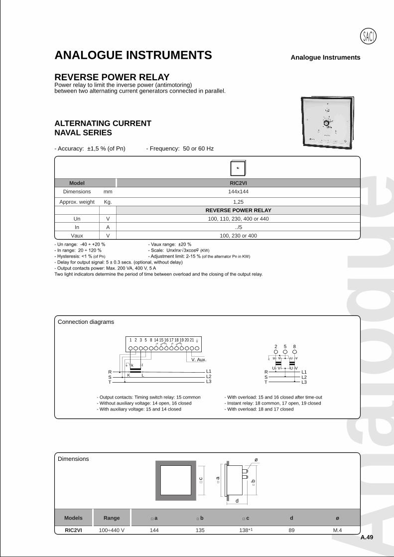
REVERSE POWER RELAYPower relay to limit the inverse power (antimotoring)between two alternating current generators connected in parallel.
c
d
b
ø
a
Models Range a b c d ø
RIC2VI 100÷440 V 144 135 138+1 89 M.4
Model RIC2VI
Dimensions mm 144x144
Approx. weight Kg. 1,25
REVERSE POWER RELAY
Un V 100, 110, 230, 400 or 440
In A ../5
Vaux V 100, 230 or 400
Dimensions
ALTERNATING CURRENTNAVAL SERIES
- Accuracy: ±1,5 % (of Pn) - Frequency: 50 or 60 Hz
2 5 8
L1L2L3
u v u v
U V U VRSTT
RS
1 2 3 8 14 15 16 17 18 19 20 21
k l
K L
V. Aux.
L1L2L3
5
Connection diagrams
- Output contacts: Timing switch relay: 15 common- Without auxiliary voltage: 14 open, 16 closed- With auxiliary voltage: 15 and 14 closed
- With overload: 15 and 16 closed after time-out- Instant relay: 18 common, 17 open, 19 closed- With overload: 18 and 17 closed

A.50
Analogue InstrumentsANALOGUE INSTRUMENTS
SYNCHRONISING RELAYElectronic relay for synchronization of two alternatingcurrent generators comparing their voltage, phase and frequency.
c
d
b
ø
a
Models Range a b c d ø
RSC2 100÷440 V 144 135 138+1 134 M.4
Model RSC2
Dimensions mm 144x144
Approx. weight Kg. 2,00
SYNCHRONISING RELAY
Un V 2x110, 230, 400 or 440
Dimensions
R S T1 2 3 5 6 7 8 9 10
U V
u v
4
G
v
u
V
U
110 220 110 220
L1 L2 L3
Connection diagrams
Output relay: 1 switching contact (max. 200 VA, 250 V, 5 A AC.)
A check adjusts the phase difference from 5 to 40 electrical degrees, and another adjusts the minimum time from 0.2 to 5 secs, during which thisdifference must be maintained.When both parameters go into the set limits, the output relay operates the synchronizing switch and an LED indicates that coupling may be carried out.To adjust operating limit, remove security cover or screw.
ALTERNATING CURRENTNAVAL SERIES
- Frequency: 50 or 60 Hz - Un range: ±15 %
Anal
ogue
A.51
Analogue InstrumentsANALOGUE INSTRUMENTS
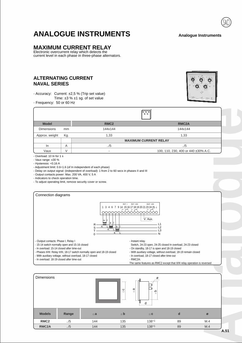
MAXIMUM CURRENT RELAYElectronic overcurrent relay which detects thecurrent level in each phase in three-phase alternators.
Model RMC2 RMC2A
Dimensions mm 144x144 144x144
Approx. weight Kg. 1,33 1,33
MAXIMUM CURRENT RELAY
In A ../5 ../5
Vaux V - 100, 110, 230, 400 or 440 ±30% A.C.
ALTERNATING CURRENTNAVAL SERIES
- Accuracy: Current: ±2,5 % (Trip set value)Time: ±3 % ±1 sg. of set value
- Frequency: 50 or 60 Hz
- Overload: 10 In for 1 s- Vaux range: ±30 %- Hysteresis: <0.16 A- Adjustment limit: 0.6÷1.6 (of In independent of each phase)- Delay on output signal: (independent of overload): 1 from 2 to 60 secs in phases II and III- Output contacts power: Max. 200 VA, 400 V, 5 A- Indicators to check operation time.- To adjust operating limit, remove security cover or screw.
c
d
b
ø
a
Models Range a b c d ø
RMC2 ../5 144 135 138+1 89 M.4
RMC2A ../5 144 135 138+1 89 M.4
Dimensions
RST
1 3 4 7 9 14 15 16 17 18 19 20
V. Aux.
L1L2L3
6 21 23 24RET. I RET. II/III INST. II/III
25
k l
K Lk l
K Lk l
K L0 N
Connection diagrams
- Instant relay.Switch, 24-23 open, 24-25 closed In overload, 24-23 closed
- On standby, 18-17 is open and 18-19 closed- With auxiliary voltage, without overload, 18-19 remain closed- In overload, 18-17 closed after time-out- RMC2A:The same features as RMC2 except that II/III relay operation is reversed
- Output contacts: Phase I, Relay I- 15-14 switch normally open and 15-16 closed- In overload: 15-14 closed after time-out- Phases II/III: Relay II/III, 18-17 switch normally open and 18-19 closed- With auxiliary voltage, without overload, 18-17 closed- In overload: 18-19 closed after time-out
A.52
Analogue InstrumentsANALOGUE INSTRUMENTS
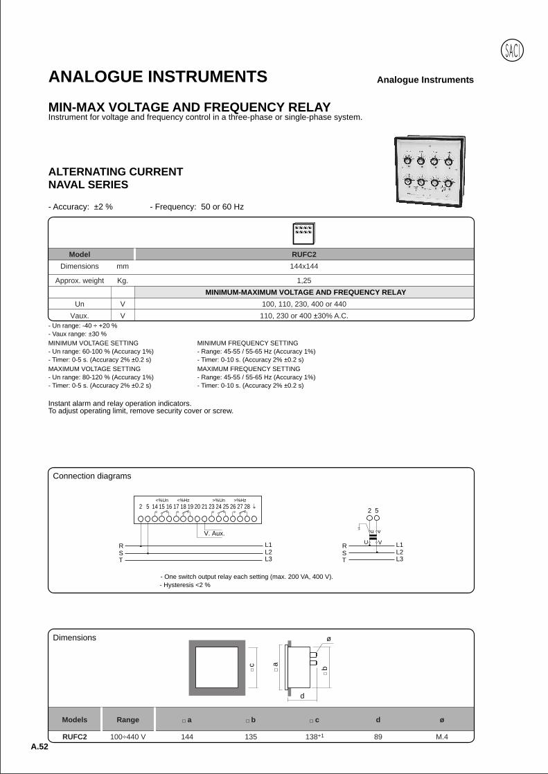
MIN-MAX VOLTAGE AND FREQUENCY RELAYInstrument for voltage and frequency control in a three-phase or single-phase system.
c
d
b
ø
a
Models Range a b c d ø
RUFC2 100÷440 V 144 135 138+1 89 M.4
- Un range: -40 ÷ +20 %- Vaux range: ±30 %MINIMUM VOLTAGE SETTING- Un range: 60-100 % (Accuracy 1%)- Timer: 0-5 s. (Accuracy 2% ±0.2 s)MAXIMUM VOLTAGE SETTING- Un range: 80-120 % (Accuracy 1%)- Timer: 0-5 s. (Accuracy 2% ±0.2 s)
Model RUFC2
Dimensions mm 144x144
Approx. weight Kg. 1,25
MINIMUM-MAXIMUM VOLTAGE AND FREQUENCY RELAY
Un V 100, 110, 230, 400 or 440
Vaux. V 110, 230 or 400 ±30% A.C.
2 5
U V
u v
RST
L1L2L3
RST
2 5 14 16 17 18 19 20 21 23 24 25
V. Aux.
L1L2L3
15 26 27 28<%Un <%Hz >%Un >%Hz
Connection diagrams
Dimensions
ALTERNATING CURRENTNAVAL SERIES
- Accuracy: ±2 % - Frequency: 50 or 60 Hz
MINIMUM FREQUENCY SETTING- Range: 45-55 / 55-65 Hz (Accuracy 1%)- Timer: 0-10 s. (Accuracy 2% ±0.2 s)MAXIMUM FREQUENCY SETTING- Range: 45-55 / 55-65 Hz (Accuracy 1%)- Timer: 0-10 s. (Accuracy 2% ±0.2 s)
Instant alarm and relay operation indicators.To adjust operating limit, remove security cover or screw.
- One switch output relay each setting (max. 200 VA, 400 V).- Hysteresis <2 %
Anal
ogue
A.53
Analogue Instruments
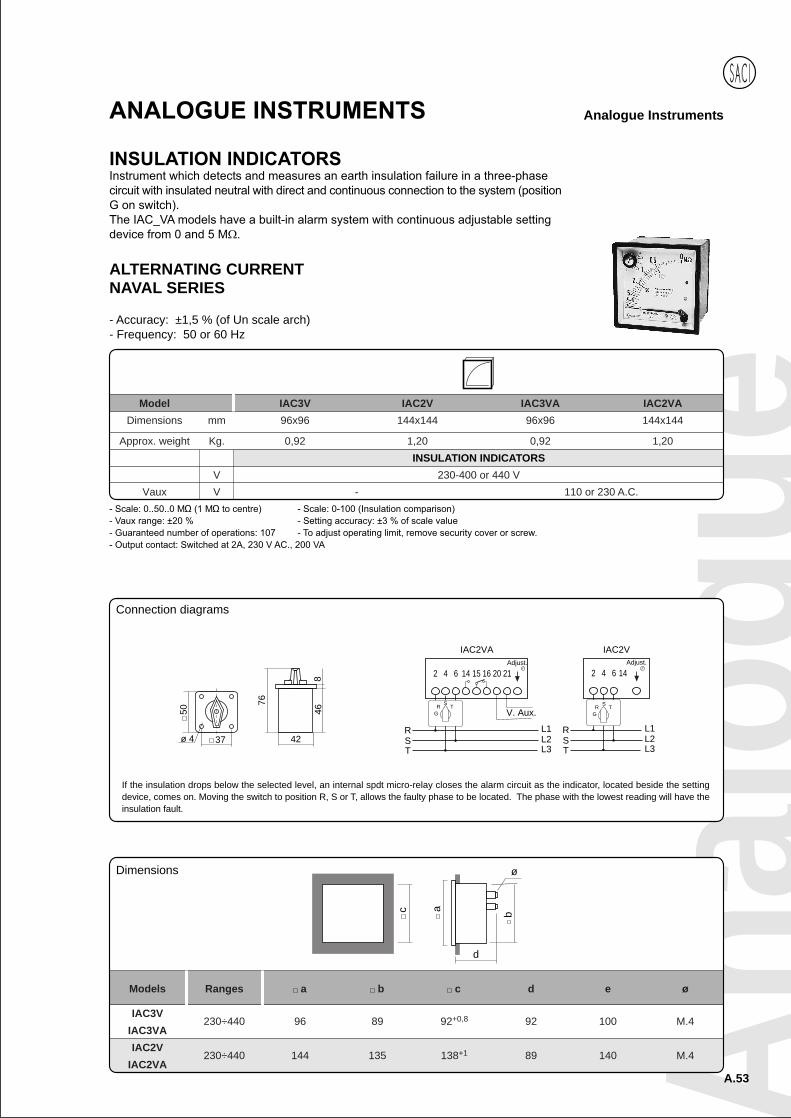
Model IAC3V IAC2V IAC3VA IAC2VA
Dimensions mm 96x96 144x144 96x96 144x144
Approx. weight Kg. 0,92 1,20 0,92 1,20
INSULATION INDICATORS
V 230-400 or 440 V
Vaux V - 110 or 230 A.C.
ALTERNATING CURRENTNAVAL SERIES
- Accuracy: ±1,5 % (of Un scale arch)- Frequency: 50 or 60 Hz
c
d
b
ø
a
Models Ranges a b c d e ø
IAC3V230÷440 96 89 92+0,8 92 100 M.4
IAC3VA
IAC2V230÷440 144 135 138+1 89 140 M.4
IAC2VA
Dimensions
Connection diagrams
If the insulation drops below the selected level, an internal spdt micro-relay closes the alarm circuit as the indicator, located beside the settingdevice, comes on. Moving the switch to position R, S or T, allows the faulty phase to be located. The phase with the lowest reading will have theinsulation fault.
76
42
468
37ø 4
50
RST
2 4 6 15 16 20 21
V. Aux.
L1L2L3
14Adjust.
GR
ST
RST
2 4 6
L1L2L3
14Adjust.
GR
ST
IAC2VA IAC2V
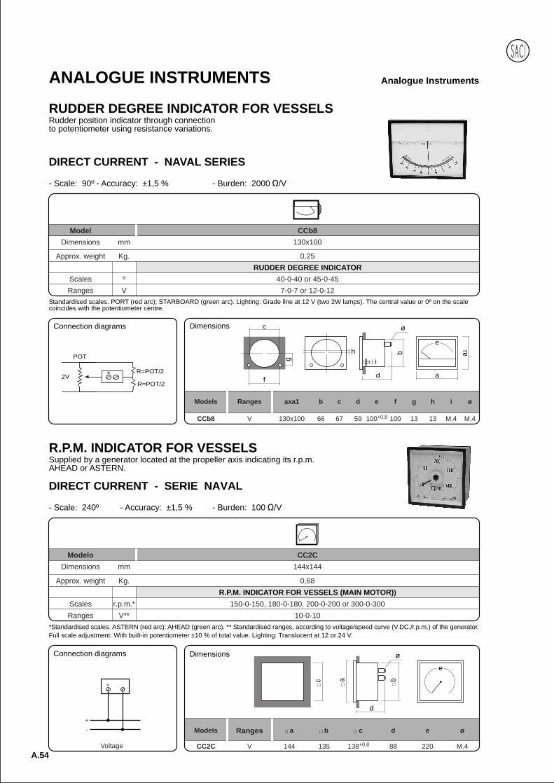
A.54
Analogue InstrumentsANALOGUE INSTRUMENTS
RUDDER DEGREE INDICATOR FOR VESSELSRudder position indicator through connectionto potentiometer using resistance variations.
DIRECT CURRENT - NAVAL SERIES
- Scale: 90º - Accuracy: ±1,5 % - Burden: 2000 /V
Model CCb8Dimensions mm 130x100
Approx. weight Kg. 0,25RUDDER DEGREE INDICATOR
Scales º 40-0-40 or 45-0-45Ranges V 7-0-7 or 12-0-12
Standardised scales. PORT (red arc); STARBOARD (green arc). Lighting: Grade line at 12 V (two 2W lamps). The central value or 0º on the scalecoincides with the potentiometer centre.
Models Ranges axa1 b c d e f g h i ø
CCb8 V 130x100 66 67 59 100+0,8 100 13 13 M.4 M.4
e
ad
b
i
ø
h
c
f
g
a1
DimensionsConnection diagrams
2VR=POT/2
R=POT/2
POT
R.P.M. INDICATOR FOR VESSELSSupplied by a generator located at the propeller axis indicating its r.p.m.AHEAD or ASTERN.
*Standardised scales. ASTERN (red arc); AHEAD (green arc). ** Standardised ranges, according to voltage/speed curve (V.DC./r.p.m.) of the generator.Full scale adjustment: With built-in potentiometer ±10 % of total value. Lighting: Translucent at 12 or 24 V.
Modelo CC2CDimensions mm 144x144
Approx. weight Kg. 0,68R.P.M. INDICATOR FOR VESSELS (MAIN MOTOR))
Scales r.p.m.* 150-0-150, 180-0-180, 200-0-200 or 300-0-300Ranges V** 10-0-10
DIRECT CURRENT - SERIE NAVAL
- Scale: 240º - Accuracy: ±1,5 % - Burden: 100 /V
Connection diagrams
Voltage
+
-
+
c a
d
b
ø
e
Models Ranges a b c d e ø
CC2C V 144 135 138+0,8 88 220 M.4
Dimensions
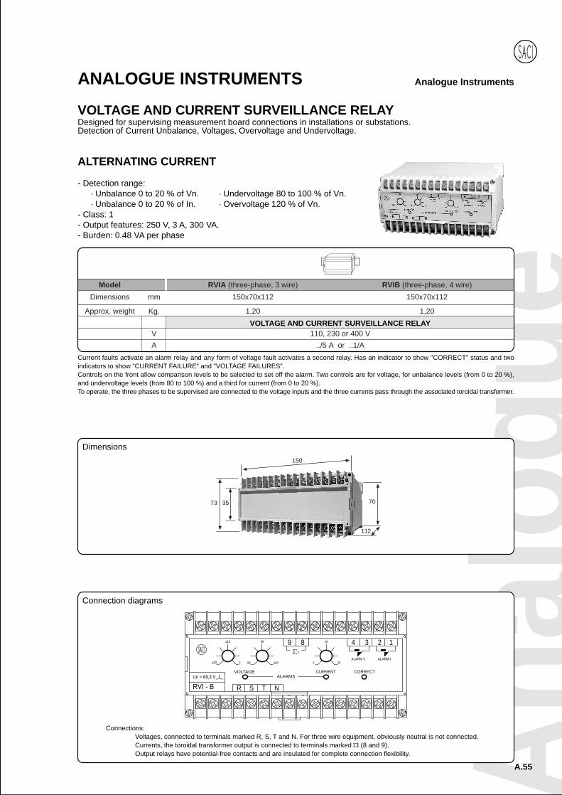
Anal
ogue
A.55
Analogue InstrumentsANALOGUE INSTRUMENTS
VOLTAGE AND CURRENT SURVEILLANCE RELAYDesigned for supervising measurement board connections in installations or substations.Detection of Current Unbalance, Voltages, Overvoltage and Undervoltage.
Model RVIA (three-phase, 3 wire) RVIB (three-phase, 4 wire)
Dimensions mm 150x70x112 150x70x112
Approx. weight Kg. 1,20 1,20
VOLTAGE AND CURRENT SURVEILLANCE RELAYV 110, 230 or 400 VA ../5 A or ..1/A
Current faults activate an alarm relay and any form of voltage fault activates a second relay. Has an indicator to show "CORRECT" status and twoindicators to show "CURRENT FAILURE" and "VOLTAGE FAILURES".Controls on the front allow comparison levels to be selected to set off the alarm. Two controls are for voltage, for unbalance levels (from 0 to 20 %),and undervoltage levels (from 80 to 100 %) and a third for current (from 0 to 20 %).To operate, the three phases to be supervised are connected to the voltage inputs and the three currents pass through the associated toroidal transformer.
ALTERNATING CURRENT
- Detection range:· Unbalance 0 to 20 % of Vn. · Undervoltage 80 to 100 % of Vn.· Unbalance 0 to 20 % of In. · Overvoltage 120 % of Vn.
- Class: 1- Output features: 250 V, 3 A, 300 VA.- Burden: 0.48 VA per phase
Connection diagrams
Connections:Voltages, connected to terminals marked R, S, T and N. For three wire equipment, obviously neutral is not connected.Currents, the toroidal transformer output is connected to terminals marked I (8 and 9).Output relays have potential-free contacts and are insulated for complete connection flexibility.
CURRENT
±20 800 100 0
VOLTAGEUn = 69,3 V
RVI - B R
ALARMS
TS N
±10 90 89
20
CORRECT
1
ALARM V
410 3 2
ALARM I
73 35
112
150
70
Dimensions